User Manual
OPERATOR’S MANUAL
Rad-87™
Pulse CO-Oximeter
Rad-87 Pulse CO-Oximeter Operator’s Manual i
The Rad-87 Operating Instructions provide the necessary information for proper operation of all models of
the Rad-87 instrument. General knowledge of pulse CO-Oximetry and an understanding of the features and
functions of the Rad-87 are a prerequisite for its proper use. Do not operate the Rad-87 without completely reading
and understanding the instructions in this manual.
NOTICE:
Purchase or possession of this instrument does not carry any express or implied license to use this instrument
with replacement parts which would, alone or in combination with this instrument, fall within the scope of one of
the patents relating to this instrument.
CAUTION:
•Federal law (U.S.) restricts this instrument to sale by or on the order of a physician.
Masimo Corporation
40 Parker
Irvine, CA 92618 USA
Tel.: 949-297-7000
Fax.: 949-297-7001
www.masimo.com
EU Authorized Representative for Masimo Corporation:
EC REP
MDSS GmbH
Schiffgraben 41
D-30175 Hannover, Germany
3149433
CONFORMS TO UL STD 60601-1,
CERTIFIED TO CAN/CSA STD C22.2 NO. 601.1
Covered by one or more of the following U.S. Patents: RE38,492, RE38,476, 7,221,971, 7,215,986, 7,215,984,
7,186,966, 6,979,812, 6,861,639, 6,850,787, 6,826,419, 6,816,741, 6,745,060, 6,699,194, 6,684,090, 6,654,624,
6,650,917, 6,643,530, 6,606,511, 6,515,273, 6,501,975, 6,463,311, 6,430,525, 6,388,240, 6,360,114, 6,263,222,
6,236,872, 6,229,856, 6,157,850, 6,067,462, 6,011,986, 6,002,952, 5,919,134, 5,769,785, 5,758,644, 5,685,299,
5,632,272, 5,490,505, 5,482,036, international equivalents, or one or more of the patents referenced at www.masimo.
com/patents.htm. Other patents pending.
© 2010 Masimo Corporation. Masimo, Discrete Saturation Transform, DST, DCI, Signal Extraction Technology,
Signal Extraction Pulse CO-Oximeter, SET, Rad, RadNet, Radical, , Signal I.Q., Pronto, FastSat, PVI, LNOP,
Rainbow, SpCO, SpMet, SpHb, and LNCS are federally registered trademarks of Masimo Corporation.
Rad-87, Pleth Variability Index, Patient SafetyNet, Rainbow SET, SpOC, APOD, Pulse CO-Oximeter, LNOPv,
M-LNCS, RI and RRa are trademarks of Masimo Corporation.

Rad-87 Pulse CO-Oximeter Operator’s Manual
ii
Safety Information, Warnings, Cautions and Notes
The Rad-87™ Pulse CO-Oximeter™ is designed to minimize the possibility of hazards from errors in the
software program by following sound engineering design processes, Risk Analysis and Software Validation.
■ Explosion hazard. Do not use the Rad-87 in the presence of fl ammable anesthetics or other fl ammable
substance in combination with air, oxygen-enriched environments, or nitrous oxide.
■ High intensity extreme lights (including pulsating strobe lights) directed on the sensor, may not allow the Pulse
CO-Oximeter to obtain readings.
■ Excessive ambient noise may affect the accuracy of the respiration rate reading from the Acoustic Respiration
Sensor.
■ SpO2 monitoring is required when monitoring RRa (Acoustic Respiration).
■ The Rad-87 is NOT intended for use as an apnea monitor.
■ The Pulse CO-Oximeter should be considered an early warning device. As a trend towards patient hypoxemia is
indicated, blood samples should be analyzed by laboratory instruments to completely understand the patient’s
condition.
■ Pulse rate measurement is based on the optical detection of a peripheral flow pulse and therefore may not
detect certain arrhythmias. The pulse oximeter should not be used as a replacement or substitute for ECG
based arrhythmia analysis.
■ The Rad-87 is to be operated by qualifi ed personnel only. This manual, accessory directions for use, all
precautionary information, and specifi cations should be read before use.
■ Electric shock hazard. Do not open the Rad-87 instrument. Only a qualifi ed operator may perform maintenance
procedures specifi cally described in this manual. Refer servicing to Masimo for repair of this equipment.
■ Ensure that the HF surgical neutral electrode is properly connected to help prevent unintended
current return paths when using high frequency (HF) surgical equipment.
■ As with all medical equipment, carefully route patient cabling to reduce the possibility of patient entanglement
or strangulation.
■ Use cables only from the instrument manufacturer to provide protection against the effects of
discharge from a cardiac defibrillator and burns.
■ Do not place the Rad-87 or accessories in any position that might cause it to fall on the patient. Do not lift the
Rad-87 by the power cord or any other cable.
■ Interfering Substances: Dyes, or any substance containing dyes, that change usual blood pigmentation may
cause erroneous readings.
■ SpO2 is empirically calibrated to functional arterial oxygen saturation in healthy adult volunteers with normal
levels of carboxyhemoglobin (COHb) and methemoglobin (MetHb). A pulse oximeter can not measure
elevated levels of COHb or MetHb. Increases in either COHb or MetHb will affect the accuracy of the SpO2
measurement.
■ For increased COHb: COHb levels above normal tend to increase the level of SpO2. The level of increase is
approximately equal to the amount of COHb that is present.
NOTE: High levels of COHb may occur with a seemingly normal SpO2. When elevated levels of COHb are
suspected, laboratory analysis (CO-Oximetry) of a blood sample should be performed.
■ For increased MetHb: the SpO2 may be decreased by levels of MetHb of up to approximately 10% to 15%.
At higher levels of MetHb, the SpO2 may tend to read in the low to mid 80s. When elevated levels of MetHb
are suspected, laboratory analysis (CO-Oximetry) of a blood sample should be performed.
■ Elevated levels of Methemoglobin (MetHb) will lead to inaccurate SpO2 and SpCO® measurements.

Rad-87 Pulse CO-Oximeter Operator’s Manual iii
■ Elevated levels of Carboxyhemoglobin (COHb) will lead to inaccurate SpO2 measurements.
■ Elevated levels of Total Bilirubin may lead to inaccurate SpO2, SpMet®, SpCO, SpHb® and SpOC™
measurements.
■ Motion artifact may lead to inaccurate SpMet, SpCO, SpHb and SpOC measurements.
■ Very low arterial Oxygen Saturation (SpO2) levels may cause inaccurate SpCO and SpMet measurements.
■ Severe anemia may cause erroneous SpO2 and SpOC readings.
■
Hemoglobin synthesis disorders may cause erroneous SpHb readings.
■ Do not use the Rad-87 or sensors during magnetic resonance imaging (MRI) scanning. Induced current
could potentially cause burns. The Rad-87 may affect the MRI image and the MRI device may affect the
accuracy of the Pulse CO-Oximetry parameters and measurements.
■ If using Rad-87 during full body radiation, keep the sensor out of the radiation fi eld. If the sensor is exposed
to the radiation, the reading might be inaccurate or the instrument might read zero for the duration of the
active irradiation period.
■ For home use, ensure that the Rad-87’s alarm can be heard from other rooms in the house especially when noisy
appliances such as vacuum cleaners, dishwashers, clothes dryers, televisions, or radios are operating.
■ Always remove the sensor from the patient and completely disconnect the patient from the Rad-87 before
bathing the patient.
■ Additional information specific to Masimo sensors including information about parameter/measurement
performance during motion and low perfusion, may be found in the sensor's Directions For Use (DFU).
■ Do not place the Rad-87 where the controls can be changed by the patient.
■ Do not place the Rad-87's face against a surface. This will cause the alarm to be muffl ed.
■ Do not place the Rad-87 on electrical equipment that may affect the Pulse CO-Oximeter, preventing it from
working properly.
■ Do not expose the Rad-87 to excessive moisture such as direct exposure to rain. Excessive moisture can
cause the instrument to perform inaccurately or fail.
■ Do not place containers with liquids on or near the Rad-87. Liquids spilled on the instrument may cause it to
perform inaccurately or fail.
■ If the Rad-87 fails any part of the setup procedures or leakage tests, remove the instrument from operation
until qualifi ed service personnel have corrected the situation.
■ Patient Safety - If a sensor is damaged in any way, discontinue use immediately.
■ Do not monitor more than a single patient at a time on the Rad-87.
■ Disposal of product - Comply with local laws in the disposal of the instrument and/or its accessories.
■ The Rad-87 can be used during defi brillation, but the readings may be inaccurate for up to 20 seconds.
■
This equipment has been tested and found to comply with the limits for medical devices to the EN
60601-1-2, Medical Device Directive 93/42/EEC and Part 15, FCC Rules/USA.
■
This
device
complies with part 15 of the FCC Rules. Operation is subject to the following two conditions:
(1) This
device
may not cause harmful interference, and (2) this
device
must accept any interference
received, including interference that may cause undesired operation.
■ This equipment generates, uses and can radiate radio frequency energy and, if not installed and
used in accordance with the instructions, may cause harmful interference to other devices in the
vicinity. However, there is no guarantee that interference will not occur in a particular installation. If this
Safety Information, Warnings, Cautions and Notes, continued

Rad-87 Pulse CO-Oximeter Operator’s Manual
iv
equipment does cause harmful interference to other devices, which can be determined by turning the
equipment off and on, the user is encouraged to try to correct the interference by one or more of the
following measures:
■ Reorient or relocate the receiving device.
■ Increase the separation between the equipment.
■ Connect the equipment into an outlet on a circuit different from that to which the other device(s) are
connected.
■ Consult the manufacturer for help.
■ In order to connect wirelessly to a compatible interface system like Patient SafetyNet™, the Rad-87
should be placed in an environment free from RF shielding, which could hinder wireless reception.
■ To minimize radio interference, other electrical equipment that emits RF transmissions should not be
in close proximity to the Rad-87.
■ Changes or modifications to the wireless radio feature whether intentional or unintentional are
prohibited without written approval from Masimo Corporation.
■ The Rad-87 (instrument with optional radio) wirelessly transmits real-time sensor connectivity status,
indicating a connect and/or disconnect state. If the instrument is in a failure mode then the radio power
is disabled and an error message is indicated on the instrument display. The instrument does not have a
powered state where no information is transmitted.
■ In accordance with FCC requirements, the Rad-87 (instrument with optional radio) must be placed
greater than 20 cm from the patient or nearby persons.
■ In accordance with FCC requirements, radio accessories on the Rad-87 (instrument with optional radio)
cannot be attached directly to the patient using any accessory containing metal components.
■ In accordance with international telecommunication requirements, the frequency band of 5,150 MHz
to 5,250 MHz is only for indoor usage to reduce potential for harmful interference to co-channel mobile
satellite systems.
■ The battery should be adequately charged to ensure backup power in case of AC power disruption.
■ A functional tester cannot be utilized to assess the accuracy of the Pulse CO-Oximeter or any sensors.
■ To ensure safety, avoid stacking multiple devices or placing anything on the instrument during operation.
■ Ensure the speaker is not covered or the instrument is placed face-down on bedding or other sound
absorbing surface.
■ To protect against injury from electric shock, follow the directions below:
■ Avoid placing the instrument on surfaces with visible liquid spills.
■ Do not soak or immerse the instrument in liquids.
■ Always turn off and disconnect the power cord from the AC power supply before cleaning the
device.
■ Use cleaning solutions sparingly.
■ Cleared Use Only: The device and related accessories are cleared by the Food and Drug Administration
(FDA) for noninvasive patient monitoring and may not be used for any processes, procedures, experiments
or any other use for which the device is not intended or cleared by the FDA, or in any manner inconsistent
with the instructions for use or labeling. The device and related accessories are not intended for use in
combination with other medical devices or in high-risk applications.
Safety Information, Warnings, Cautions and Notes, continued

Rad-87 Pulse CO-Oximeter Operator’s Manual v
Safety Information, Warnings, Cautions and Notes . . . . . . . . . . . . . . . . . . . . . . . . . . . . . . . ii
SECTION 1 - OVERVIEW
About This Manual . . . . . . . . . . . . . . . . . . . . . . . . . . . . . . . . . . . . . . . . . . . . . . . . . . . . . . 1-1
Warnings, Cautions and Notes. . . . . . . . . . . . . . . . . . . . . . . . . . . . . . . . . . . . . . . . . . . . . 1-2
Product Description . . . . . . . . . . . . . . . . . . . . . . . . . . . . . . . . . . . . . . . . . . . . . . . . . . . . . 1-3
Features . . . . . . . . . . . . . . . . . . . . . . . . . . . . . . . . . . . . . . . . . . . . . . . . . . . . . . . . 1-3
Optional Features . . . . . . . . . . . . . . . . . . . . . . . . . . . . . . . . . . . . . . . . . . . . . . . . . 1-3
Indications for Use. . . . . . . . . . . . . . . . . . . . . . . . . . . . . . . . . . . . . . . . . . . . . . . . . 1-4
Pulse CO-Oximetry . . . . . . . . . . . . . . . . . . . . . . . . . . . . . . . . . . . . . . . . . . . . . . . . . . . . . 1-4
SpO2 General Description. . . . . . . . . . . . . . . . . . . . . . . . . . . . . . . . . . . . . . . . . . . 1-4
SpCO General Description . . . . . . . . . . . . . . . . . . . . . . . . . . . . . . . . . . . . . . . . . . 1-4
SpMet General Description . . . . . . . . . . . . . . . . . . . . . . . . . . . . . . . . . . . . . . . . . . 1-4
SpHb (Total Hemoglobin) General Description . . . . . . . . . . . . . . . . . . . . . . . . . . . 1-5
CaO2 (Total Arterial Oxygen Content) General Description . . . . . . . . . . . . . . . . . .1-5
SpOC (Pulse CO-Oximetry) General Description. . . . . . . . . . . . . . . . . . . . . . . . . 1-5
Rainbow Acoustic Monitoring General Description . . . . . . . . . . . . . . . . . . . . . . . 1-5
Principle of Operation . . . . . . . . . . . . . . . . . . . . . . . . . . . . . . . . . . . . . . . . . . . . . . 1-6
Functional Saturation . . . . . . . . . . . . . . . . . . . . . . . . . . . . . . . . . . . . . . . . . . . . . . 1-7
Rad-87 vs. Drawn Whole Blood Measurements . . . . . . . . . . . . . . . . . . . . . . . . . . 1-7
Masimo SET Signal Extraction Technology for SpO2 Measurements . . . . . . . . . 1-7
SpMet, SpCO, and SpHb Measurements During Patient Motion . . . . . . . . . . . . . 1-7
Rainbow Acoustic Monitoring . . . . . . . . . . . . . . . . . . . . . . . . . . . . . . . . . . . . . . . . 1-8
FastSat . . . . . . . . . . . . . . . . . . . . . . . . . . . . . . . . . . . . . . . . . . . . . . . . . . . . . . . . . 1-9
Masimo Rainbow SET Parallel Engines . . . . . . . . . . . . . . . . . . . . . . . . . . . . . . . 1-10
Masimo SET DST® . . . . . . . . . . . . . . . . . . . . . . . . . . . . . . . . . . . . . . . . . . . . . . 1-10
SECTION 2 - SYSTEM DESCRIPTION
Introduction. . . . . . . . . . . . . . . . . . . . . . . . . . . . . . . . . . . . . . . . . . . . . . . . . . . . . . . . . . . . 2-1
Rad-87 Pulse CO-Oximeter - Horizontal . . . . . . . . . . . . . . . . . . . . . . . . . . . . . . . . . . . . . 2-2
Rad-87 Pulse CO-Oximeter - Vertical . . . . . . . . . . . . . . . . . . . . . . . . . . . . . . . . . . . . . . . 2-5
Rad-87 Rear Panel. . . . . . . . . . . . . . . . . . . . . . . . . . . . . . . . . . . . . . . . . . . . . . . . . . . . . . 2-6
Symbols . . . . . . . . . . . . . . . . . . . . . . . . . . . . . . . . . . . . . . . . . . . . . . . . . . . . . . . . . . . . . . 2-7
LCD Display . . . . . . . . . . . . . . . . . . . . . . . . . . . . . . . . . . . . . . . . . . . . . . . . . . . . . . . . . . . 2-8
SECTION 3 - SETUP
Rad-87 Setup . . . . . . . . . . . . . . . . . . . . . . . . . . . . . . . . . . . . . . . . . . . . . . . . . . . . . . . . . . 3-1
Introduction . . . . . . . . . . . . . . . . . . . . . . . . . . . . . . . . . . . . . . . . . . . . . . . . . . . . . . 3-1
Unpacking and Inspection . . . . . . . . . . . . . . . . . . . . . . . . . . . . . . . . . . . . . . . . . . . 3-1
Preparation for Monitoring. . . . . . . . . . . . . . . . . . . . . . . . . . . . . . . . . . . . . . . . . . . 3-1
Rad-87 Power Requirements . . . . . . . . . . . . . . . . . . . . . . . . . . . . . . . . . . . . . . . . 3-1
Initial Battery Charging . . . . . . . . . . . . . . . . . . . . . . . . . . . . . . . . . . . . . . . . . . . . . 3-2
Initial Installation . . . . . . . . . . . . . . . . . . . . . . . . . . . . . . . . . . . . . . . . . . . . . . . . . . 3-2
System Interface Setup . . . . . . . . . . . . . . . . . . . . . . . . . . . . . . . . . . . . . . . . . . . . . . . . . . 3-3
Philips VueLink Setup . . . . . . . . . . . . . . . . . . . . . . . . . . . . . . . . . . . . . . . . . . . . . . 3-3
RadNet Setup . . . . . . . . . . . . . . . . . . . . . . . . . . . . . . . . . . . . . . . . . . . . . . . . . . . . 3-3
Patient SafetyNet Setup . . . . . . . . . . . . . . . . . . . . . . . . . . . . . . . . . . . . . . . . . . . . 3-3
Table of Contents

Rad-87 Pulse CO-Oximeter Operator’s Manual
vi
SECTION 4 - OPERATION
Introduction. . . . . . . . . . . . . . . . . . . . . . . . . . . . . . . . . . . . . . . . . . . . . . . . . . . . . . . . . . . . 4-1
Basic Operation . . . . . . . . . . . . . . . . . . . . . . . . . . . . . . . . . . . . . . . . . . . . . . . . . . . . . . . . 4-1
General Setup and Use. . . . . . . . . . . . . . . . . . . . . . . . . . . . . . . . . . . . . . . . . . . . . 4-1
Default Settings . . . . . . . . . . . . . . . . . . . . . . . . . . . . . . . . . . . . . . . . . . . . . . . . . . . 4-4
Factory Default and User Configurable Settings. . . . . . . . . . . . . . . . . . . . . . . . . . 4-4
Successful Monitoring . . . . . . . . . . . . . . . . . . . . . . . . . . . . . . . . . . . . . . . . . . . . . . . . . . . 4-5
Masimo Pulse CO-Oximetry Sensors . . . . . . . . . . . . . . . . . . . . . . . . . . . . . . . . . . . . . . . 4-6
Masimo Acoustic Respiration Sensors. . . . . . . . . . . . . . . . . . . . . . . . . . . . . . . . . . . . . . . 4-6
Sensor Time Remaining . . . . . . . . . . . . . . . . . . . . . . . . . . . . . . . . . . . . . . . . . . . . 4-7
Liquid Crystal Display (LCD) . . . . . . . . . . . . . . . . . . . . . . . . . . . . . . . . . . . . . . . . . 4-7
Light Emitting Diodes (LED) Display . . . . . . . . . . . . . . . . . . . . . . . . . . . . . . . . . . . 4-9
Numeric Display - SpO2 . . . . . . . . . . . . . . . . . . . . . . . . . . . . . . . . . . . . . . . . . . 4-10
Numeric Display - Pulse Rate . . . . . . . . . . . . . . . . . . . . . . . . . . . . . . . . . . . . . . . 4-10
Numeric display - RRa . . . . . . . . . . . . . . . . . . . . . . . . . . . . . . . . . . . . . . . . . . . . 4-10
Numeric Display - SpCO . . . . . . . . . . . . . . . . . . . . . . . . . . . . . . . . . . . . . . . . . . . 4-10
Numeric Display - SpHb . . . . . . . . . . . . . . . . . . . . . . . . . . . . . . . . . . . . . . . . . . . 4-11
Numeric Display - SpOC . . . . . . . . . . . . . . . . . . . . . . . . . . . . . . . . . . . . . . . . . . . 4-11
Numeric Display - PI . . . . . . . . . . . . . . . . . . . . . . . . . . . . . . . . . . . . . . . . . . . . . . 4-11
Numeric Display - PVI . . . . . . . . . . . . . . . . . . . . . . . . . . . . . . . . . . . . . . . . . . . . . 4-12
Low Perfusion . . . . . . . . . . . . . . . . . . . . . . . . . . . . . . . . . . . . . . . . . . . . . . . . . . . 4-12
Signal Indication and Quality Indicator (SIQ) . . . . . . . . . . . . . . . . . . . . . . . . . . . 4-12
Low SpCO SIQ and Low SpMet SIQ . . . . . . . . . . . . . . . . . . . . . . . . . . . . . . . . . 4-12
Low SpHb . . . . . . . . . . . . . . . . . . . . . . . . . . . . . . . . . . . . . . . . . . . . . . . . . . . . . . 4-13
Signal Indication and Quality Indicator - Acoustic (SIQa) . . . . . . . . . . . . . . . . . 4-13
Acoustic Respiration Sensor Placement . . . . . . . . . . . . . . . . . . . . . . . . . . . . . . 4-13
Rainbow SET, Masimo SET Sensor Placement . . . . . . . . . . . . . . . . . . . . . . . . . 4-14
Sensitivity . . . . . . . . . . . . . . . . . . . . . . . . . . . . . . . . . . . . . . . . . . . . . . . . . . . . . . 4-15
Low Battery Audible Alarm . . . . . . . . . . . . . . . . . . . . . . . . . . . . . . . . . . . . . . . . . 4-16
Normal Patient Monitoring . . . . . . . . . . . . . . . . . . . . . . . . . . . . . . . . . . . . . . . . . . . . . . . 4-16
Parameter/Measurement Selection . . . . . . . . . . . . . . . . . . . . . . . . . . . . . . . . . . . 4-16
Setup Menu . . . . . . . . . . . . . . . . . . . . . . . . . . . . . . . . . . . . . . . . . . . . . . . . . . . . . . . . . . 4-17
Menu Navigation . . . . . . . . . . . . . . . . . . . . . . . . . . . . . . . . . . . . . . . . . . . . . . . . . 4-17
Setup Menu Level 1 . . . . . . . . . . . . . . . . . . . . . . . . . . . . . . . . . . . . . . . . . . . . . . . . . . . . 4-18
Parameter/Measurement Alarm Limits - Screen 1 . . . . . . . . . . . . . . . . . . . . . . . 4-18
Parameter/Measurement Alarm Limits - Screen 2 . . . . . . . . . . . . . . . . . . . . . . . 4-19
Parameter/Measurement Alarm Limits - Screen 3 . . . . . . . . . . . . . . . . . . . . . . . 4-20
LED Brightness . . . . . . . . . . . . . . . . . . . . . . . . . . . . . . . . . . . . . . . . . . . . . . . . . . 4-20
Sensitivity . . . . . . . . . . . . . . . . . . . . . . . . . . . . . . . . . . . . . . . . . . . . . . . . . . . . . . 4-21
Setup Menu Level 2 . . . . . . . . . . . . . . . . . . . . . . . . . . . . . . . . . . . . . . . . . . . . . . . . . . . . 4-22
Alarm Volume . . . . . . . . . . . . . . . . . . . . . . . . . . . . . . . . . . . . . . . . . . . . . . . . . . . 4-22
SpO2 Alarm Delay . . . . . . . . . . . . . . . . . . . . . . . . . . . . . . . . . . . . . . . . . . . . . . . 4-22
RRa Alarm Delay . . . . . . . . . . . . . . . . . . . . . . . . . . . . . . . . . . . . . . . . . . . . . . . . 4-23
Clear Trend . . . . . . . . . . . . . . . . . . . . . . . . . . . . . . . . . . . . . . . . . . . . . . . . . . . . . 4-23
Button Volume . . . . . . . . . . . . . . . . . . . . . . . . . . . . . . . . . . . . . . . . . . . . . . . . . . . 4-24
FastSat . . . . . . . . . . . . . . . . . . . . . . . . . . . . . . . . . . . . . . . . . . . . . . . . . . . . . . . . 4-24
Trend Setup and Use . . . . . . . . . . . . . . . . . . . . . . . . . . . . . . . . . . . . . . . . . . . . . . . . . . . 4-25
Introduction . . . . . . . . . . . . . . . . . . . . . . . . . . . . . . . . . . . . . . . . . . . . . . . . . . . . . 4-25
TrendCom Utility Installation . . . . . . . . . . . . . . . . . . . . . . . . . . . . . . . . . . . . . . . . 4-25
TrendCom Utility Operation . . . . . . . . . . . . . . . . . . . . . . . . . . . . . . . . . . . . . . . . . 4-25
Table of Contents

Rad-87 Pulse CO-Oximeter Operator’s Manual vii
Table of Contents
Download Trend Data from Rad-87. . . . . . . . . . . . . . . . . . . . . . . . . . . . . . . . . . . 4-25
Erasing Trend Memory . . . . . . . . . . . . . . . . . . . . . . . . . . . . . . . . . . . . . . . . . . . . 4-26
Setup Menu Level 3 . . . . . . . . . . . . . . . . . . . . . . . . . . . . . . . . . . . . . . . . . . . . . . . . . . . . 4-27
SpO2 Averaging Time . . . . . . . . . . . . . . . . . . . . . . . . . . . . . . . . . . . . . . . . . . . . . 4-27
SpHb Averaging . . . . . . . . . . . . . . . . . . . . . . . . . . . . . . . . . . . . . . . . . . . . . . . . . 4-28
PVI Averaging . . . . . . . . . . . . . . . . . . . . . . . . . . . . . . . . . . . . . . . . . . . . . . . . . . . 4-28
PI Averaging . . . . . . . . . . . . . . . . . . . . . . . . . . . . . . . . . . . . . . . . . . . . . . . . . . . . 4-29
RRa Averaging . . . . . . . . . . . . . . . . . . . . . . . . . . . . . . . . . . . . . . . . . . . . . . . . . . 4-29
RRa Sensor Status Notifications. . . . . . . . . . . . . . . . . . . . . . . . . . . . . . . . . . . . . 4-30
Rapid Desat Limit . . . . . . . . . . . . . . . . . . . . . . . . . . . . . . . . . . . . . . . . . . . . . . . . 4-30
Alarm On/Off . . . . . . . . . . . . . . . . . . . . . . . . . . . . . . . . . . . . . . . . . . . . . . . . . . . . 4-30
Optical Sensor Off Audible Alarm Latch . . . . . . . . . . . . . . . . . . . . . . . . . . . . . . . 4-31
Default Settings . . . . . . . . . . . . . . . . . . . . . . . . . . . . . . . . . . . . . . . . . . . . . . . . . . 4-31
Device Profile Setup and Use . . . . . . . . . . . . . . . . . . . . . . . . . . . . . . . . . . . . . . . 4-32
SmartTone On/Off . . . . . . . . . . . . . . . . . . . . . . . . . . . . . . . . . . . . . . . . . . . . . . . . 4-33
Year . . . . . . . . . . . . . . . . . . . . . . . . . . . . . . . . . . . . . . . . . . . . . . . . . . . . . . . . . . . 4-33
Month . . . . . . . . . . . . . . . . . . . . . . . . . . . . . . . . . . . . . . . . . . . . . . . . . . . . . . . . . 4-34
Day . . . . . . . . . . . . . . . . . . . . . . . . . . . . . . . . . . . . . . . . . . . . . . . . . . . . . . . . . . . 4-34
Hour. . . . . . . . . . . . . . . . . . . . . . . . . . . . . . . . . . . . . . . . . . . . . . . . . . . . . . . . . . . 4-34
Minute . . . . . . . . . . . . . . . . . . . . . . . . . . . . . . . . . . . . . . . . . . . . . . . . . . . . . . . . . 4-35
Software Version . . . . . . . . . . . . . . . . . . . . . . . . . . . . . . . . . . . . . . . . . . . . . . . . . 4-35
Serial Output . . . . . . . . . . . . . . . . . . . . . . . . . . . . . . . . . . . . . . . . . . . . . . . . . . . . 4-35
Interface Alarms . . . . . . . . . . . . . . . . . . . . . . . . . . . . . . . . . . . . . . . . . . . . . . . . . 4-36
Nurse Call . . . . . . . . . . . . . . . . . . . . . . . . . . . . . . . . . . . . . . . . . . . . . . . . . . . . . . 4-37
Polarity. . . . . . . . . . . . . . . . . . . . . . . . . . . . . . . . . . . . . . . . . . . . . . . . . . . . . . . . . 4-37
Line Frequency . . . . . . . . . . . . . . . . . . . . . . . . . . . . . . . . . . . . . . . . . . . . . . . . . . 4-37
Parameter/Measurement Select - Screen 1 . . . . . . . . . . . . . . . . . . . . . . . . . . . . 4-38
Parameter/Measurement Select - Screen 2 . . . . . . . . . . . . . . . . . . . . . . . . . . . . 4-38
Parameter/Measurement Select - Screen 3 . . . . . . . . . . . . . . . . . . . . . . . . . . . . 4-39
SpHb Precision . . . . . . . . . . . . . . . . . . . . . . . . . . . . . . . . . . . . . . . . . . . . . . . . . . 4-39
SpHb Calculation. . . . . . . . . . . . . . . . . . . . . . . . . . . . . . . . . . . . . . . . . . . . . . . . . 4-39
LCD Language . . . . . . . . . . . . . . . . . . . . . . . . . . . . . . . . . . . . . . . . . . . . . . . . . . 4-40
SpHb Display. . . . . . . . . . . . . . . . . . . . . . . . . . . . . . . . . . . . . . . . . . . . . . . . . . . . 4-40
Set Mode . . . . . . . . . . . . . . . . . . . . . . . . . . . . . . . . . . . . . . . . . . . . . . . . . . . . . . . 4-40
Home Mode Operation. . . . . . . . . . . . . . . . . . . . . . . . . . . . . . . . . . . . . . . . . . . . . . . . . . 4-41
Sleep Mode Operation . . . . . . . . . . . . . . . . . . . . . . . . . . . . . . . . . . . . . . . . . . . . . . . . . . 4-41
Enable/Disable Radio . . . . . . . . . . . . . . . . . . . . . . . . . . . . . . . . . . . . . . . . . . . . . 4-41
LCD Display Function with Radio Configured and Enabled . . . . . . . . . . . . . . . . 4-42
SECTION 5 - ALARMS AND MESSAGES
Alarm Identification. . . . . . . . . . . . . . . . . . . . . . . . . . . . . . . . . . . . . . . . . . . . . . . . . . . . . . 5-1
Alarm Category Table . . . . . . . . . . . . . . . . . . . . . . . . . . . . . . . . . . . . . . . . . . . . . . 5-1
Alarm Limits . . . . . . . . . . . . . . . . . . . . . . . . . . . . . . . . . . . . . . . . . . . . . . . . . . . . . . . . . . . 5-2
Alarm Limit: User Configurable Settings . . . . . . . . . . . . . . . . . . . . . . . . . . . . . . . 5-3
Alarm Priorities. . . . . . . . . . . . . . . . . . . . . . . . . . . . . . . . . . . . . . . . . . . . . . . . . . . . . . . . . 5-4
Multiple Parameter/Measurement Alarms . . . . . . . . . . . . . . . . . . . . . . . . . . . . . . . . . . . . 5-5
Alarm Priority for Display Screens . . . . . . . . . . . . . . . . . . . . . . . . . . . . . . . . . . . . 5-5
Alarm Silence . . . . . . . . . . . . . . . . . . . . . . . . . . . . . . . . . . . . . . . . . . . . . . . . . . . . 5-6
Alarm Bell . . . . . . . . . . . . . . . . . . . . . . . . . . . . . . . . . . . . . . . . . . . . . . . . . . . . . . . 5-7
System Status Light . . . . . . . . . . . . . . . . . . . . . . . . . . . . . . . . . . . . . . . . . . . . . . . 5-7

Rad-87 Pulse CO-Oximeter Operator’s Manual
viii
Alarm Mute . . . . . . . . . . . . . . . . . . . . . . . . . . . . . . . . . . . . . . . . . . . . . . . . . . . . . . 5-8
Messages . . . . . . . . . . . . . . . . . . . . . . . . . . . . . . . . . . . . . . . . . . . . . . . . . . . . . . . . . . . . . 5-9
SECTION 6 - TROUBLESHOOTING
Troubleshooting . . . . . . . . . . . . . . . . . . . . . . . . . . . . . . . . . . . . . . . . . . . . . . . . . . . . . . . . 6-1
SECTION 7 - SPECIFICATIONS
Rad-87 Specifications . . . . . . . . . . . . . . . . . . . . . . . . . . . . . . . . . . . . . . . . . . . . . . . . . . . 7-1
Serial Interface Specifications . . . . . . . . . . . . . . . . . . . . . . . . . . . . . . . . . . . . . . . . . . . . . 7-4
Serial Interface Setup . . . . . . . . . . . . . . . . . . . . . . . . . . . . . . . . . . . . . . . . . . . . . . 7-4
Serial Printer Setup . . . . . . . . . . . . . . . . . . . . . . . . . . . . . . . . . . . . . . . . . . . . . . . . 7-4
Nurse Call Specifications . . . . . . . . . . . . . . . . . . . . . . . . . . . . . . . . . . . . . . . . . . . . . . . . . 7-5
SECTION 8 - SENSORS & PATIENT CABLES
Introduction. . . . . . . . . . . . . . . . . . . . . . . . . . . . . . . . . . . . . . . . . . . . . . . . . . . . . . . . . . . . 8-1
Selecting a Masimo SET Sensor . . . . . . . . . . . . . . . . . . . . . . . . . . . . . . . . . . . . . 8-1
Sensor Application Instructions. . . . . . . . . . . . . . . . . . . . . . . . . . . . . . . . . . . . . . . 8-1
Masimo Acoustic Respiration Sensor. . . . . . . . . . . . . . . . . . . . . . . . . . . . . . . . . . . . . . . . 8-2
Masimo Rainbow Sensors . . . . . . . . . . . . . . . . . . . . . . . . . . . . . . . . . . . . . . . . . . . . . . . . 8-2
Rainbow Reusable Sensors . . . . . . . . . . . . . . . . . . . . . . . . . . . . . . . . . . . . . . . . . 8-2
Rainbow Direct Connect Sensors . . . . . . . . . . . . . . . . . . . . . . . . . . . . . . . . . . . . . 8-2
Rainbow R Series Adhesive Sensors . . . . . . . . . . . . . . . . . . . . . . . . . . . . . . . . . . 8-3
Rainbow ReSposable™ Pulse CO-Oximeter Sensor System . . . . . . . . . . . . . . . 8-4
Masimo SpO2 Sensors . . . . . . . . . . . . . . . . . . . . . . . . . . . . . . . . . . . . . . . . . . . . . . . . . . 8-4
ReSposable™ Pulse CO-Oximeter Sensor System . . . . . . . . . . . . . . . . . . . . . . 8-4
Red Direct Connect Sensors. . . . . . . . . . . . . . . . . . . . . . . . . . . . . . . . . . . . . . . . . 8-4
LNOP® Reusable Sensors . . . . . . . . . . . . . . . . . . . . . . . . . . . . . . . . . . . . . . . . . 8-5
LNOPv™ Adhesive Sensors . . . . . . . . . . . . . . . . . . . . . . . . . . . . . . . . . . . . . . . . 8-5
LNOP Specialty Sensors . . . . . . . . . . . . . . . . . . . . . . . . . . . . . . . . . . . . . . . . . . . 8-5
M-LNCS™/LNCS® Reusable Sensors . . . . . . . . . . . . . . . . . . . . . . . . . . . . . . . . 8-5
M-LNCS™/LNCS® Adhesive Sensors . . . . . . . . . . . . . . . . . . . . . . . . . . . . . . . . . 8-6
M-LNCS™/LNCS® Specialty Sensors . . . . . . . . . . . . . . . . . . . . . . . . . . . . . . . . . 8-6
Sensor Accuracy . . . . . . . . . . . . . . . . . . . . . . . . . . . . . . . . . . . . . . . . . . . . . . . . . . . . . . . 8-7
Cleaning And Reuse Of Masimo Reusable Sensors and Cables . . . . . . . . . . . . . . . . . . 8-7
Reattachment of a Single Use Acoustic Respiration Sensor . . . . . . . . . . . . . . . . . . . . . 8-7
Reattachment of a Single Use Rainbow SET or Masimo SET Adhesive Sensor . . . . . . 8-7
SECTION 9 - SERVICE & MAINTENANCE
Introduction. . . . . . . . . . . . . . . . . . . . . . . . . . . . . . . . . . . . . . . . . . . . . . . . . . . . . . . . . . . . 9-1
Cleaning . . . . . . . . . . . . . . . . . . . . . . . . . . . . . . . . . . . . . . . . . . . . . . . . . . . . . . . . . . . . . . 9-1
Battery Service. . . . . . . . . . . . . . . . . . . . . . . . . . . . . . . . . . . . . . . . . . . . . . . . . . . . . . . . . 9-2
Performance Verification. . . . . . . . . . . . . . . . . . . . . . . . . . . . . . . . . . . . . . . . . . . . . . . . . . 9-2
Service and Repair. . . . . . . . . . . . . . . . . . . . . . . . . . . . . . . . . . . . . . . . . . . . . . . . . . . . . . 9-3
Repair Policy . . . . . . . . . . . . . . . . . . . . . . . . . . . . . . . . . . . . . . . . . . . . . . . . . . . . . 9-3
Return Procedure . . . . . . . . . . . . . . . . . . . . . . . . . . . . . . . . . . . . . . . . . . . . . . . . . 9-4
Sales & End-User License Agreement. . . . . . . . . . . . . . . . . . . . . . . . . . . . . . . . . . . . . . . 9-5
Warranty . . . . . . . . . . . . . . . . . . . . . . . . . . . . . . . . . . . . . . . . . . . . . . . . . . . . . . . . 9-5
Exclusions . . . . . . . . . . . . . . . . . . . . . . . . . . . . . . . . . . . . . . . . . . . . . . . . . . . . . . . 9-5
End-User License . . . . . . . . . . . . . . . . . . . . . . . . . . . . . . . . . . . . . . . . . . . . . . . . . 9-6
Restrictions. . . . . . . . . . . . . . . . . . . . . . . . . . . . . . . . . . . . . . . . . . . . . . . . . . . . . . . . . . . . 9-7
No Implied License . . . . . . . . . . . . . . . . . . . . . . . . . . . . . . . . . . . . . . . . . . . . . . . . . . . . . 9-7
Table of Contents

Rad-87 Pulse CO-Oximeter Operator’s Manual ix
Sensors Licensed for Monitoring Use Only . . . . . . . . . . . . . . . . . . . . . . . . . . . . . . . . . . 9-7
SECTION 10 - PART NUMBERS
Part Numbers . . . . . . . . . . . . . . . . . . . . . . . . . . . . . . . . . . . . . . . . . . . . . . . . . . . . . . . . . 10-1
Table of Contents

Rad-87 Pulse CO-Oximeter Operator’s Manual 1-1
1
Overview
About This Manual
This manual explains how to set up and use the Rad-87 Pulse CO-Oximeter containing Masimo
Rainbow SET technology. Important safety information relating to general use of the Rad-87
appears before this introduction. Other important safety information is located throughout the
manual where appropriate.
Read the entire safety information section before you operate the monitor.
In addition to the safety section, this manual includes the following sections:
SECTION 1 Overview gives a general description of Rad-87 Pulse CO-Oximeter.
SECTION 2 System Description describes the Rad-87 Pulse CO-Oximeter system
and its functions and features.
SECTION 3 Setup describes how to setup the Rad-87 Pulse CO-Oximeter for use.
SECTION 4 Operation describes the operation of the Rad-87 Pulse CO-Oximeter
system.
SECTION 5 Alarms and Messages describes the alarm system messages.
SECTION 6 Troubleshooting describes troubleshooting information.
SECTION 7 Specifications gives the detailed specifi cations of the Rad-87 Pulse
CO-Oximeter.
SECTION 8 Sensors & Patient Cables outlines how to use and care for compatible
Masimo sensors and cables.
SECTION 9 Service & Maintenance describes how to maintain, service and obtain
repair for the Rad-87 instrument. The Sales and End User License
Agreement, including Warranty, is also in this section.
SECTION 10 Part Numbers lists the part numbers of the different language Operator's
Manuals that are available for the Rad-87 Pulse CO-Oximeter.

1-2 Rad-87 Pulse CO-Oximeter Operator’s Manual
1Overview
Warnings, Cautions and Notes
Please read and follow any warnings, cautions and notes presented throughout this
manual. An explanation of these labels are as follows:
A WARNING is provided when actions may result in a serious outcome (i.e., injury,
serious adverse affect, death) to the patient or user. Look for text in a gray shaded box.
Sample of Warning:
WARNING: THIS IS A SAMPLE OF A WARNING STATEMENT.
A CAUTION is given when any special care is to be exercised by the patient or user to avoid
injury to the patient, damage to this instrument or damage to other property.
Sample of Caution:
CAUTION:
•This is a sample of a caution statement.
A NOTE is provided when extra general information is applicable.
Sample of Note:
NOTE: This is a sample of a note.

Rad-87 Pulse CO-Oximeter Operator’s Manual 1-3
1
Overview
Product Description
The Rad-87 Pulse CO-Oximeter Monitor is a noninvasive, arterial oxygen, carboxyhemoglobin,
methemoglobin saturation, total hemoglobin concentration, total arterial oxygen content, pulse
rate and respiration rate monitor. The Rad-87 features an LED display screen that continuously
displays numeric values for SpO2, SpCO*, SpMet*, SpHb*, total arterial oxygen content (SpOC*),
perfusion index (PI), pleth variability index* (PVI), pulse rate and respiratory/respiration rate
(RRa*). It also provides bar graph displays for quick visual identification of Signal I.Q.® (SIQ™),
perfusion index (PI), acoustic Signal Identification Quality (SIQa*) and Respiration Indicator (RI*).
The Rad-87 is available in four models: vertical Rad-87, horizontal Rad-87, vertical Rad-87 with
radio and horizontal Rad-87 with radio.
Features
These features are common to Rad-87 monitors:
■ Masimo SET is clinically proven to be the highest sensitivity and specificity pulse CO-Oximeter
technology in the world.
■ Rainbow technology continuously and noninvasively measures arterial oxygen saturation (SpO2) and
pulse rate (BPM), as well as providing a reliable probe-off detection.
■ Perfusion Index (PI) with trending capability indicates arterial pulse signal strength during low
perfusion.
■ Accurate on cyanotic infants with congenital heart disease when used with an LNOP Blue Sensor.
■ Signal I.Q. provides signal identification and quality indication during excessive motion and low signal
to noise situations.
■ FastSat® tracks rapid changes in arterial O2 saturation with high fidelity.
■ Variable pitch provides tonal variance for every 1% change in saturation.
■ Remote alarming interface.
■ Up to 72 hours of trending. (See Section 4, Trend Setup and Use.)
■ Allows user to customize the default settings and set the instrument to retain these settings through
a power off/on cycle.
■ The LCD Display allows the user to view a scrolling marque of (installed) parameter/measurement
alarm limits, system information, and wireless radio communication (wireless radio model only).
Optional Features
■ Rainbow technology uses 7+ wavelengths of light to continuously and noninvasively measure
carboxyhemoglobin (SpCO), methemoglobin (SpMet) and total hemoglobin (SpHb), as well as
providing a reliable probe-off detection.
■ Rainbow Acoustic Monitoring uses acoustic monitoring technology to measure and display
respiration rate (RRa) while providing the Respiration Indicator (RI) at the sensor site.
■ Pleth Variability Index (PVI)† may show changes that reflect physiologic factors such as vascular
tone, circulating blood volume, and intrathoracic pressure excursions.
■ Total arterial oxygen content (SpOC) provides a calculated measurement of the amount of oxygen
in arterial blood which may provide useful information for both oxygen dissolved in plasma and
combined with hemoglobin.
■ Provides an 802.11a/b/g wireless radio interface with compatible systems (wireless radio model only).
■ Ability to connect to Masimo Patient SafetyNet through a wireless network (wireless radio model only).
* Optional features: SpCO, SpMet, SpHb, SpOC, PVI, RRa, RI, SIQa
† The utility of PVI is unknown at this time and requires further clinical studies. Technical factors that may affect PVI
include probe malposition and patient motion.
1-4 Rad-87 Pulse CO-Oximeter Operator’s Manual
1Overview
Indications for Use
The Masimo Rainbow SET® Rad-87 Pulse CO-Oximeter and accessories are indicated for
the continuous, non-invasive monitoring of functional oxygen saturation of arterial hemoglobin
(SpO2), pulse rate, carboxyhemoglobin saturation (SpCO), methemoglobin saturation (SpMet),
total hemoglobin concentration and/or respiratory rate (RRa).The Masimo Rainbow SET Rad-87
Pulse CO-Oximeter and accessories are indicated for use with adult, pediatric and neonatal
patients during both motion and no motion conditions, and for patients who are well or poorly
perfused in hospitals, hospital-type facilities, mobile and home environments.
Note: Please refer to the sensor Directions for Use (DFU) for specific indications.
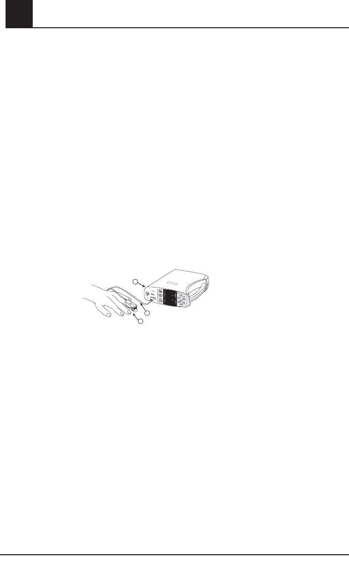
Pulse CO-Oximetry
SpO2 General Description
Pulse CO-Oximetry is a continuous and noninvasive method of measuring the level of arterial
oxygen saturation in blood. The measurement is taken by placing a sensor on a patient, usually
on the fingertip for adults and the hand or foot for neonates. The sensor is connected to the Pulse
CO-Oximetry instrument with a patient cable. The sensor collects signal data from the patient and
sends it to the instrument.
The following figure shows the general monitoring setup.
SpCO General Description
Pulse CO-Oximetry is a continuous and noninvasive method of measuring the levels of
carboxyhemoglobin concentration (SpCO) in arterial blood. It relies on the same basic principles
of pulse oximetry (spectrophotometry) to make its SpCO measurement. The measurement is
obtained by placing a sensor on a patient, usually on the fingertip for adults and the hand or foot
for infants. The sensor connects either directly to the Pulse CO-Oximetry instrument or through
an instrument patient cable. The sensor collects signal data from the patient and sends it to the
instrument. The instrument displays the calculated data as percentage value for the SpCO, which
reflect blood levels of carbon monoxide bound to hemoglobin.
SpMet General Description
Pulse CO-Oximetry is a continuous and noninvasive method of measuring the levels of
methemoglobin concentration (SpMet) in arterial blood. It relies on the same basic principles
of pulse oximetry (spectrophotometry) to make its SpMet measurement. The measurement is
obtained by placing a sensor on a patient, usually on the fingertip for adults and the hand or foot
for infants. The sensor connects either directly to the Pulse CO-Oximetry instrument or through
an instrument patient cable. The sensor collects signal data from the patient and sends it to the
1. Instrument
2. Patient Cable
3. Sensor
NORM
APOD MAX
SENSITIVITY
MODE
rbc monitor
3
2
1
12
97
76
RRa
SIQa
RI

Rad-87 Pulse CO-Oximeter Operator’s Manual 1-5
1
Overview
instrument. The instrument displays the calculated data as percentage value for the SpMet.
SpHb (Total Hemoglobin) General Description
Pulse CO-Oximetry is a continuous and noninvasive method of measuring the levels of total
hemoglobin (SpHb) in arterial blood. It relies on the same principles of pulse oximetry to make
the SpHb measurement. The measurement is taken by a sensor capable of measuring SpHb,
usually on the fingertip for adults and pediatric patients. The sensor connects directly to the
Pulse CO-Oximeter or with a patient cable. The sensor collects signal data from the patient and
sends it to the instrument. The instrument displays the calculated data as measurement of total
hemoglobin concentration. The Rad-87 can be configured to be a combined SpO2 monitor with
other available parameters/measurements.
CaO2 (Total Arterial Oxygen Content) General Description*
Oxygen (O2) is carried in the blood in two forms, either dissolved in plasma or combined with
hemoglobin. The amount of oxygen in the arterial blood is termed the oxygen content (CaO2)
and is measured in units of ml O2/dl blood. One gram of hemoglobin (Hb) can carry 1.34 ml of
oxygen, whereas 100 ml of blood plasma may carry approximately 0.3 ml of oxygen. The oxygen
content is determined mathematically as:
CaO2 = 1.34 (ml O2/g Hb) x Hb (g/dL) x HbO2 + PaO2 (mm Hg) x (0.3 ml O2/ 100 mm Hg/dL)
Where HbO2 is the fractional arterial oxygen saturation and PaO2 is the partial pressure of
arterial oxygen.
For typical PaO2 values, the second part of the above equation [PaO2 (mm Hg) x (0.3 ml O2/ 100 mm
Hg/dL] is approximately 0.3 ml/dl. Furthermore, for typical carboxyhemoglobin and methemoglobin
levels, the functional saturation (SpO2) as measured by a pulse oximeter is given by:
SpO2 = 1.02 x HbO2
* Martin, Laurence. All You Really Need to Know to Interpret Arterial Blood Gases, Second Edition. New York: Lippincott
Williams & Wilkins, 1999.
SpOC (Pulse CO-Oximetry) General Description
The above approximations result in the following reduced equation for oxygen content via the
Pulse CO-Oximeter:
SpOC (ml/dl†) = 1.31 (ml O2/g Hb) x SpHb (g/dL) x SpO2 + 0.3 ml/dl
† When ml O2/g Hb is multiplied by g/dL of Hb, the gram unit in the denominator of ml/g cancels the gram unit in the
numerator of g/dL resulting in ml/dl (ml of oxygen in one dl of blood) as the unit of measure for SpOC.
Rainbow Acoustic Monitoring General Description
Rainbow Acoustic Monitoring continuously measures a patient's respiration rate based on airflow
sounds generated in the upper airway. The Acoustic Respiration Sensor translates airflow
sounds generated in the upper airway to an electrical signal that can be processed to produce a
respiration rate, measured as breaths per minute.
1-6 Rad-87 Pulse CO-Oximeter Operator’s Manual
1Overview
Principle of Operation
Pulse CO-Oximetry is governed by the following principles:
1. Oxyhemoglobin (oxygenated blood), deoxyhemoglobin (non-oxygenated blood),
carboxyhemoglobin (blood with carbon monoxide content), methemoglobin (blood with
oxidized hemoglobin) and blood plasma constituents differ in their absorption of visible and
infrared light (using spectrophotometry, see figure below).
Carboxyhemoglobin
Oxyhemoglobin
Methemoglobin
Deoxyhemoglobin
Absorption Spectra
Plasma
Absorption (1/mm)
0
0.5
600 800
1.0
1.5
2.0
2.5
3.0
3.5
4.0
1000 1200 1400 1600
Wavelength (nm)
2. The amount of arterial blood in tissue changes with your pulse (photoplethysography).
Therefore, the amount of light absorbed by the varying quantities of arterial blood changes
as well.
The Rad-87 Pulse CO-Oximeter uses a multi-wavelength sensor to distinguish between
oxygenated blood, deoxygenated blood, blood with carbon monoxide, oxidized blood and blood
plasma. The Rad-87 utilizes a sensor with various light-emitting diodes (LEDs) that pass light
through the site to a photodiode (detector). See figure below. Signal data is obtained by passing
various visible and infrared lights (LED’s, 500 to 1400nm) through a capillary bed (for example,
a fingertip, a hand, a foot) and measuring changes in light absorption during the blood pulsatile
cycle. This information may be useful to clinicians. The maximum radiant power of the strongest
light is rated at ≤ 25mW. The detector receives the light, converts it into an electronic signal and
sends it to the Rad-87 for calculation.
Once the Rad-87 receives the signal from the sensor, it utilizes Masimo Rainbow SET signal
extraction technology to calculate the patient’s functional arterial oxygen saturation, blood levels
of carboxyhemoglobin (SpCO), methemoglobin (SpMet) and pulse rate. The SpCO and SpMet
measurements rely on a multiwavelength calibration equation to quantify the percentage of
carbon monoxide and methemoglobin in arterial blood. In an ambient temperature of 35º C the
maximum skin surface temperature has been measured at less than 106º F (41º C), verified by
Masimo sensor skin temperature test procedure.
2
11. Light Emitting Diodes (LEDs)
( 7+ wavelengths )
2. Detector

Rad-87 Pulse CO-Oximeter Operator’s Manual 1-7
1
Overview
Functional Saturation
The Rad-87 is calibrated to measure and display functional saturation (SpO2): the amount of
oxyhemoglobin expressed as a percentage of the hemoglobin that is available to transport oxygen.
Rad-87 vs. Drawn Whole Blood Measurements
When SpO2, SpCO, SpMet and SpHb measurements obtained from the Rad-87 (noninvasive)
are compared to drawn whole blood (invasive) measurements by blood gas and/or laboratory
CO-Oximetry methods, caution should be taken when evaluating and interpreting the results.
The blood gas and/or laboratory CO-Oximetry measurements may differ from the SpO2, SpCO,
SpMet and SpHb measurements of the Rad-87 Pulse CO-Oximeter. In the case of SpO2, different
results are usually obtained from the arterial blood gas sample if the calculated measurement
is not appropriately corrected for the effects of variables that shift the relationship between the
partial pressure of oxygen (PO2) and saturation, such as: pH, temperature, the partial pressure
of carbon dioxide (PCO2), 2,3-DPG, and fetal hemoglobin. In the case of SpCO, different results
are also expected if concentration of methemoglobin in the blood gas sample is elevated. High
levels of bilirubin may cause erroneous SpO2, SpMet, SpCO and SpHb readings. As blood
samples are usually taken over a period of 20 seconds (the time it takes to draw the blood)
a meaningful comparison can only be achieved if the oxygen saturation, carboxyhemoglobin
and methemoglobin concentration of the patient are stable and not changing over the period of
time that the blood gas sample is taken. Subsequently, blood gas and laboratory CO-Oximetry
measurements of SpO2, SpCO, SpMet and SpHb may vary with the rapid administration of fluids
and in procedures such as dialysis. Additionally, drawn, whole-blood testing can be affected by
sample handling methods and time elapsed between blood draw and sample testing.
Masimo SET Signal Extraction Technology for SpO2 Measurements
Masimo Signal Extraction Technology’s signal processing differs from conventional pulse
oximeters. Conventional pulse oximeters assume that arterial blood is the only blood moving
(pulsating) in the measurement site. During patient motion, however, the venous blood also
moves, causing conventional pulse oximeters to read low values, because they cannot distinguish
between the arterial and venous blood movement (sometimes referred to as noise). Masimo SET
pulse oximetry utilizes parallel engines and adaptive digital filtering. Adaptive filters are powerful
because they are able to adapt to the varying physiologic signals and/or noise and separate them
by looking at the whole signal and breaking it down to its fundamental components. The Masimo
SET signal processing algorithm, Discrete Saturation Transform® (DST®) reliably identifies the
noise, isolates it and, using adaptive filters, cancels it. It then reports the true arterial oxygen
saturation for display on the monitor.
SpMet, SpCO, and SpHb Measurements During Patient Motion
The Rad-87 displays measurements of SpCO, SpMet and SpHb during patient motion. However,
because of the changes in the physiological parameters such as blood volume, arterial-venous
coupling, etc. that occur during patient motion, the accuracy of such measurements may not be
reliable during excessive motion. When the Rad-87 does not have confidence in the value of a
parameter due to poor signal quality caused by excessive motion or other signal interference, the
measurement for the parameter will alternate with "---".
1-8 Rad-87 Pulse CO-Oximeter Operator’s Manual
1
Rainbow Acoustic Monitoring
Rainbow Acoustic Monitoring is a real time, continuous, non-invasive method for measuring
respiration rate based on respiratory sounds. Respiratory sounds include sounds related to
respiration such as breath sounds (during inspiration and expiration), adventitious sounds, cough
sounds, snoring sounds, sneezing sounds, and sounds from the respiratory muscles [1]. These
respiratory sounds often have different characteristics depending on the location of recording [2]
and they originate in the large airways where air velocity and air turbulence induce vibration in the
airway wall. These vibrations are transmitted, for example, through the lung tissue, thoracic wall
and trachea to the surface where they may be heard with the aid of a stethoscope, a microphone
or more sophisticated devices.
Rainbow Acoustic Monitoring Architecture
The following figure illustrates how a respiratory sound produced by a patient can be turned into
a numerical measurement that corresponds to a respiratory parameter.
Patient Sensor Acquisiton
System
Signal
Processing
Respiratory
Airflow to
Sound
Sound to
Electrical
Signal
Electrical
Signal to
Digital Signal
Digital Signal
to Respiratory
Measurement
Envelope
Detection
RRa
Estimation
Patient
The generation of respiratory sounds is primarily related to turbulent respiratory airflow in upper
airways. Sound pressure waves within the airway gas and airway wall motion contribute to the
vibrations that reach the body surface and are recorded as respiratory sounds. Although the
spectral shape of respiratory sounds varies widely from person to person, it is often reproducible
within the same person, likely reflecting the strong influence of individual airway anatomy [2-6].
Sensor
The sensor captures and transmits respiratory sounds (and other biological sounds) much like
a microphone does. When subjected to a mechanical strain, (e.g., surface vibrations generated
during breathing), the sensor becomes electrically polarized. The degree of polarization is
proportional to the applied strain. This is known as the ‘Piezoelectric effect’ in this manual. The
output of the sensor is an electric signal that includes a sound signal that is modulated by
inspiratory and expiratory phases of the respiratory cycle.
Acquisition System
The acquisition system converts the electrical signal provided by the sensor into a digital signal.
This format allows the signal to be processed by a computing device.
Overview

Rad-87 Pulse CO-Oximeter Operator’s Manual 1-9
1
Overview
Signal Processing
The digital signal produced by the acquisition system is converted into a measurement that
corresponds to the respiratory parameter of interest. As shown in the figure on the previous page,
this can be performed by, for example, determining the digital signal envelope or outline which in
turn may be utilized to determine the respiratory rate. In this way, a real-time, continuous breath
rate parameter can be obtained and displayed on a monitor which, in many cases, may be real-
time and continuous.
The respiratory cycle envelope signal processing principle is similar to methods that sample
airway gases and subsequently determine a respiratory rate.
[1] A.R.A. Sovijärvi, F. Dalmasso, J. Vanderschool, L.P. Malmberg, G. Righini, S.A.T. Stoneman. Definition of terms for
applications of respiratory sounds. Eur Respir Rev 2000; 10:77, 597-610.
[2] Z. Moussavi. Fundamentals of respiratory sounds analysis. Synthesis lectures on biomedical engineering #8. Morgan
& Claypool Publishers, 2006.
[3] Olsen, et al. Mechanisms of lung sound generation. Semin Respir Med 1985; 6: 171-179.
[4] Pastercamp H, Kraman SS, Wodicka GR. Respiratory sounds – Advances beyond the stethoscope. Am J Respir Crit
Care Med 1977; 156: 974-987.
[5] Gavriely N, Cugell DW. Airflow effects on amplitude and spectral content of normal breath sounds. J Appl Physiol
1996; 80: 5-13.
[6] Gavrieli N, Palti Y, Alroy G. Spectral characteristics of normal breath sounds. J Appl Physiol 1981; 50: 307-314.
FastSat
FastSat enables rapid tracking of arterial oxygen saturation changes. Arterial oxygen saturation
data is averaged using pulse oximeter averaging algorithms to smooth the trend. When the Rad-
87 is set to FastSat “On”, the averaging algorithm evaluates all the saturation values providing
an averaged saturation value that is a better representation of the patient’s current oxygenation
status. With FastSat, the averaging time is dependent on the input signal.
1-10 Rad-87 Pulse CO-Oximeter Operator’s Manual
1Overview
Masimo Rainbow SET Parallel Engines
Masimo SET DST®
This fi gure is for conceptual purposes only.
SpOC
12
FST
MST

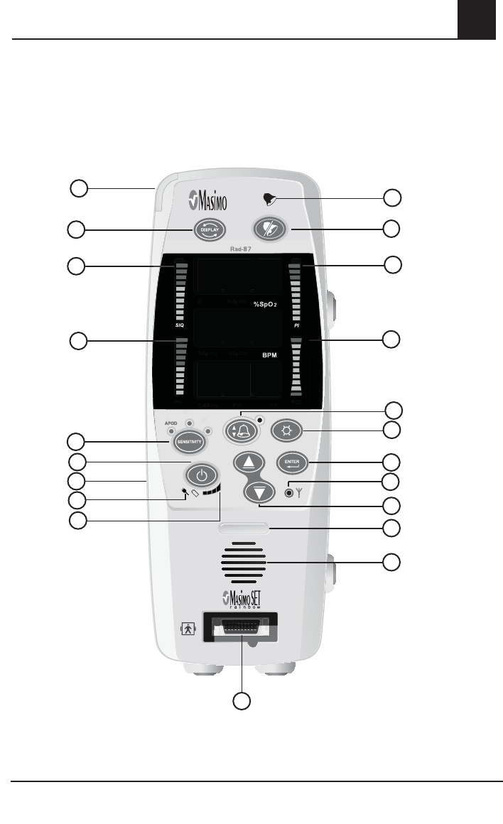
Rad-87 Pulse CO-Oximeter Operator’s Manual 2-1
2
System Description
Introduction
The Rad-87 Pulse CO-Oximeters are full featured devices designed for ease of operation. All
pulse CO-Oximetry measurement information, as well as instrument status data, is displayed on
the front panel of the device. All user input is handled by control buttons on the front panel. The
sensor cable connections are located on the left side of the front panel for the Rad-87 horizontal
instrument and the bottom of the front panel for the Rad-87 vertical device.
■ Rad-87 offers full Masimo SET technology in a small compact device.
■ Rad-87 supports the full line of Masimo sensors and patient cables (see Section 8,
Sensors and Patient Cables).
■ Rad-87 supports standardization of sensors, and pulse CO-Oximetry technology
throughout the hospital.
■ The LCD Display identifies system settings, monitoring modes, alarm limits and
information from Patient SafetyNet or Philips VueLink (when connected). The LCD is located on
top of the instrument (Horizontal) or on the left of the instrument (Vertical).
2-2 Rad-87 Pulse CO-Oximeter Operator’s Manual
2System Description
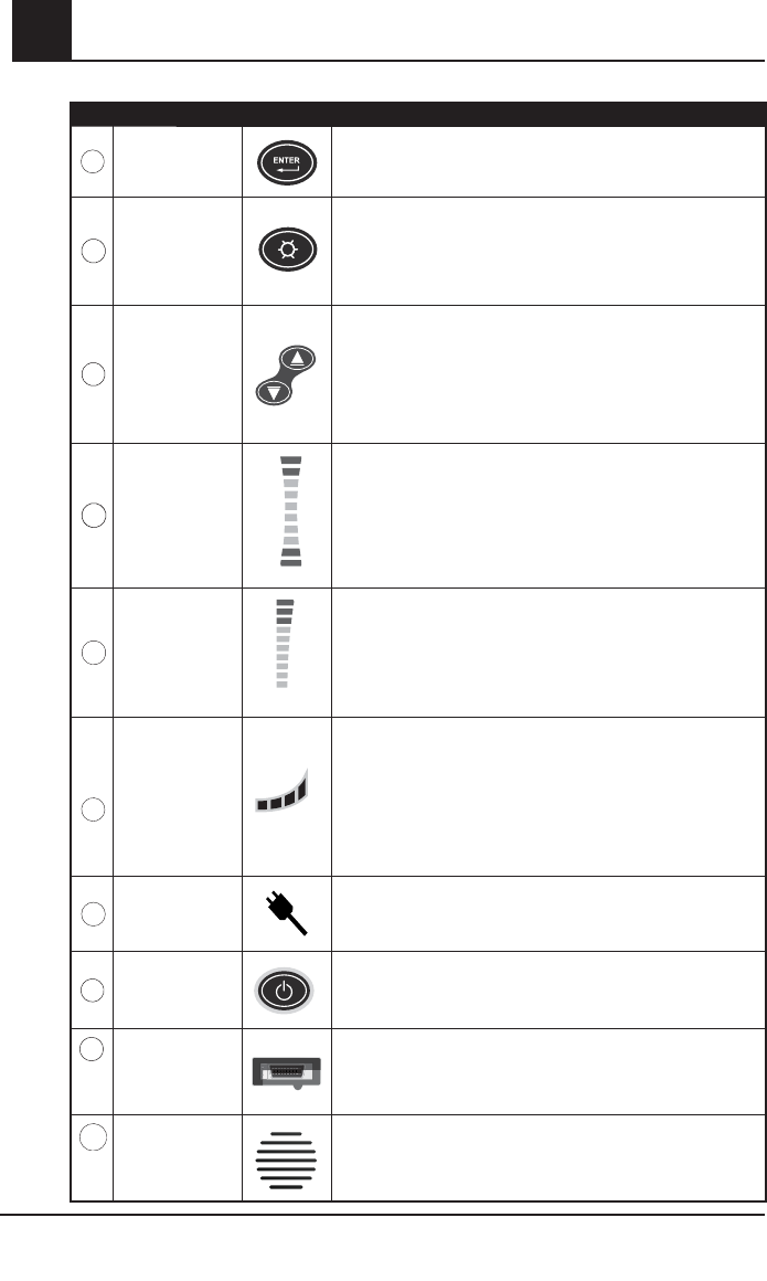
CONTROL / INDICATOR DESCRIPTION
1
Device Profile
LED
The Device (instrument) Profile LED illuminates when the instru-
ment has been set to user configured "default" settings. Upon
power up, the user configured default settings are retained and
the Device Profile LED remain lit.
When user configured default settings are active, any changes
to the default settings cause the Device Profile LED to turn off
until the instrument is returned to the user configured default
settings or powered off.
2
Sensitivity
Button/Indicator
Used to set the instrument into Maximum Sensitivity, Normal
Sensitivity, or APOD Mode.
3
LCD Display
1234567890123456
0123456789123456
The LCD display identifies system settings, monitoring modes,
alarm limits, and information from Patient SafetyNet or Philips
VueLink (when connected).
4
Signal I.Q. Index
The Signal I.Q. provides an indication of the quality of the
acquired signal as well as the timing of the pulse. A green verti-
cal LED bar rises and falls with the pulse, where the height of
the bar indicates the quality of the signal.
5
Perfusion Index The Perfusion Index provides an indication of the percentage of
pulsatile signal to non pulsatile signal.
Rad-87 Pulse CO-Oximeter - Horizontal
NORM
APOD MAX
SENSITIVITY
MODE
rbc monitor
Rad-87
APOD
APOD
MAX
MAX
SENSITIVITY
DISPLAY
NORM
NORM
ENTER
NORM
APOD MAX
SENSITIVITY
MODE
rbc monitor
Rad-87
APOD
APOD
MAX
MAX
SENSITIVITY
DISPLAY
NORM
NORM
ENTER
RI
RRa
SIQa
12
1 3
2456789
12
13
14
1110
1618 17
19
20
21 15
Rad-87 Pulse CO-Oximeter Operator’s Manual 2-3
2
System Description
CONTROL / INDICATOR DESCRIPTION
6
Wireless
Indicator
Off: No connection to Masimo Patient SafetyNet or other com-
patible interface system.
Flashing Green: Rad-87 attempts to connect to Patient
SafetyNet or other compatible interface system.
Solid Green: Rad-87 is connected to the Patient SafetyNet or
other compatible interface system.
7
Alarm Limits
Button
Used to enter the alarm menu to adjust Hi/Low SpO2, SpCO,
SpMet, SpHb, PI, PVI, RRa and pulse rate alarm limits.
The LED indicator (located above the Alarm Limits Button) will
illuminate when one or more of the factory default alarm settings is
changed to alert the user to verify alarm settings.
8
Display Button
DISPLAY
DISPLAY
Allows movement through the 3 different display screens to view
sets of parameters and measurements.
Also used to exit setup menu screens and return the display to
screen 1.
Press and hold the button down for 5 seconds to scroll through
instrument settings on the LCD Display.
9
Alarm Bell The Alarm Bell flashes red to indicate a high priority alarm.
10
Alarm Silence
Button
Press the Alarm Silence Button to temporarily silence patient
and low battery alarms. Press the Alarm Silence Button
when the “SEN OFF” message is flashing (i.e. the sensor is
removed from the patient) to acknowledge the end of monitor-
ing. In this state, all further alarms are silenced until the Pulse
CO-Oximeter starts measuring patient parameters/measure-
ments again.
NOTE: The alarm silence time can be set for 120, 90, 60 and
30 seconds.
11
System Status
Light
Solid Green: Collecting data, no alarms.
Solid Yellow:
1. low priority alarms.
2. Not monitoring and no alarms.
3. Sleep Mode.
4. Interface Alarms "Alarm Tones Off".
5. RRa mode only, no alarms.
Flashing Yellow:
1. Low parameter/measurement confidence.
2. Medium priority alarms.
Flashing Red: High priority alarms.
2-4 Rad-87 Pulse CO-Oximeter Operator’s Manual
2System Description
CONTROL / INDICATOR DESCRIPTION
12
Enter Button Used to enter the setup menus and to select/activate certain
entries within the menu/setup system.
13
Brightness
Button
Controls the level of the brightness for the LED display by provid-
ing 4 levels of brightness. Each press of the button increases
the brightness one level. Once level 4 is accessed, an additional
press of the button returns the brightness to level 1. Press the
Enter Button to save the desired choice.
14
Up Button
Down Button
Use these buttons to adjust the volume of the pulse beep tone.
Within the menu/setup system, these buttons are used to select
values within each menu option or the numeric value for the
parameter/measurement alarm feature.
Pressing and holding down these buttons allow for the rapid
scrolling of alarm limits.
15
Respiration
Indicator
RI
The Respiration Indicator (RI) displays the level of sound that is
detected by the Acoustic Respiration Sensor. A tall vertical line
indicates a high sound level, while a short vertical line indicates
a low sound level. During SpO2 only or combined SpO2 and
Rainbow Acoustic Monitoring, the bar will be green. During
Rainbow Acoustic Monitoring only, the bar will be orange.
16
Rainbow
Acoustic
Monitoring
Signal Quality
SIQa
The Rainbow Acoustic Monitoring Signal Quality (SIQa) displays
the confidence in the RRa value displayed on the monitor. A tall
vertical line indicates high confidence, while a short vertical line
indicates low confidence. During SpO2 only or combined SpO2
and Rainbow Acoustic Monitoring, the bar will be green. During
Rainbow Acoustic Monitoring only, the bar will be orange.
17
Battery Charge
Level Indicator
Provides a visual representation of the battery charge status.
When plugged into an AC outlet, only the first bar is illuminated.
When unplugged, bars illuminate to indicate battery charge. As
the battery discharges power, bar illumination decreases from
right to left.
A low battery status is indicated by a low audible beep and the
first battery bar to the left flashing green.
18
AC Power
Indicator
The AC Power Indicator is illuminated when the Rad-87 is con-
nected to AC power and during battery charging.
19
Power Button
Used to turn the instrument on and off. Press the button once
to power on the device. Press the button for 2 seconds to power
off the device.
20
Pulse
CO-Oximeter
Patient Cable
Connector
Connects to a Masimo Pulse CO-Oximeter sensor or Masimo
Pulse CO-Oximeter Patient Cable with a sensor.
21
Speaker Provides audible indication of alarm conditions, pulse tone and
feedback for key-presses.
Rad-87 Pulse CO-Oximeter Operator’s Manual 2-5
2
888
888
888
888
888
888
888
888
88
8
88
8
MAX
MAX
NORM
NORM
12
97
76
RI
RRa
SIQa
System Description
Rad-87 Pulse CO-Oximeter - Vertical
11
810
9
13
2
12
6
16
19
3
20
5
7
11
14
21
4
15
18
17
2-6 Rad-87 Pulse CO-Oximeter Operator’s Manual
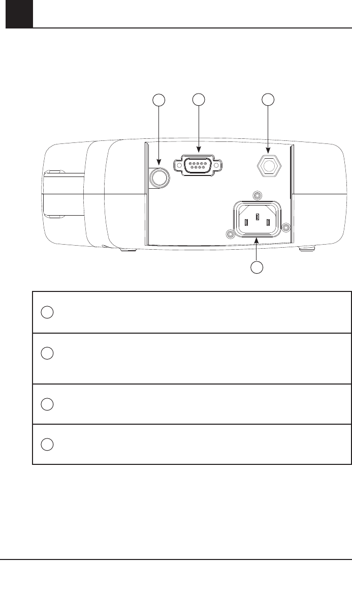
2System Description
1Nurse Call
Connector
Use the 1/4” round Connector to interface with a nurse call system.
This is a stereo output and should be utilized with a stereo cable. All
external device connections to the Nurse Call Connector must be IEC-
60950 compliant.
2Serial Output
Connector
Use the Serial Output Connector to connect a serial device, including a
serial printer, RadNet Interface Module, or PC, to the Rad-87. See Section
7, Output Interface Specifications. All external device connections to the
Serial Output Connector must be IEC-60950 compliant.
3
Equipotential
Ground
Connector
Use the Equipotential Ground Connector for grounding.
4
AC Power
Receptacle
For continuous operation and/or battery recharging, plug the AC power
cord into an AC power receptacle.
Rad-87 Rear Panel
2
13
4
Rad-87 Pulse CO-Oximeter Operator’s Manual 2-7
2
System Description
Symbols
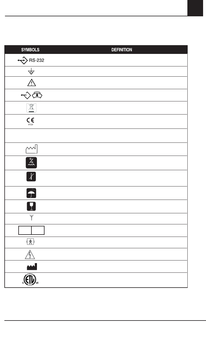
The following symbols may be found on the Rad-87 or packaging and are defined below:
RS-232
Equipotential Ground Terminal
Consult accompanying documents
Nurse Call Interface
WEEE compliant
Mark of Conformity to European Medical Device Directive 93/42/EEC
Rx Only
Federal law restricts this instrument to sale by or on the order of a
physician (USA audiences only)
Year of manufacture
5%-95% RH
Storage humidity range: 10% to 95%
-40 C
+70 C
+1060 hPa - +500 hPa
7
95 mmHg - 375 mmHg
Storage temperature range: -40˚C to +70˚C
Storage altitude range: 500 mbar to 1060 mbar
Keep dry
Fragile/breakable, handle with care
Indicates wireless Radio signal (wireless radio model only)
EC REP EU authorized representative
Defi brillation Proof Type BF
Caution
Manufacturer
Electrical Testing Laboratory certification

2-8 Rad-87 Pulse CO-Oximeter Operator’s Manual
2System Description
LCD Display
The LCD Display shows radio communication information when radio communication is active
(wireless radio model only). It also shows system information. All Rad-87 models are equipped
with an LCD display which is located on the top panel of a horizontal model, or on the left side
panel of a vertical model.
The LCD Display illuminates upon start up and displays the installed parameter/measurement's
low and high alarm limits. Once the Rad-87 completes system initiation, the display light turns off.
As the front panel buttons are pressed, each menu selection is shown on the LCD Display.
When Rad-87 actively communicates with another system using the radio feature, the LCD
Display shows the following:
■ Patient SafetyNet: The LCD Display shows the information sent from the Patient
SafetyNet to the Rad-87.
■ Philips VueLink: The LCD Display shows "VueLink Conn" and "Alarm Tones On" or
"Alarm Tones Off".
NOTE: When the Rad-87 is interfaced to the Philips VueLink and the LCD Display shows
"Alarm Tones On", audible alarms are active at the instrument. When the LCD Display
shows "Alarm Tones Off", audible alarms are inactive at the instrument.
If the Display Button is pressed down for 5 seconds, the LCD Display shows the following settings
three times and then returns to the default screen. The display cycle can be interrupted by
pressing any button except for the Sensitivity or the Alarm Silence Buttons.
■ System Settings
■ Monitoring Mode: Normal, Sleep or Home
■ Installed parameter/measurement's low and high alarm limits
■ Sensor Time (if applicable)
■ Audible Alarm
■ Alarm Volume
■ Alarm Silence
■ Alarm Delay
■ Rapid Desat
■ Sensitivity
■ Averaging Time

Rad-87 Pulse CO-Oximeter Operator’s Manual 3-1
3
Rad-87 Setup
Introduction
Before the Rad-87 Pulse CO-Oximeter can be used in a clinical setting, it needs to be inspected,
properly setup and the batteries need to be fully charged.
Unpacking and Inspection
Remove the instrument from the shipping carton and examine it for signs of shipping damage.
Check all materials against the packing list. Save all packing materials, invoice and bill of lading.
These may be required to process a claim with the carrier.
If anything is missing or damaged, contact the Technical Service Department. The contact
address and phone numbers are listed in Section 9, Service and Repair.
Preparation for Monitoring
The following sections of the manual describe the preparation, set-up and initial installation of
the Rad-87 Pulse CO-Oximeter.
Rad-87 Power Requirements
Always use a hospital grade, AC power cable to connect the Rad-87 to an AC power source.
Verify the AC power voltage and frequency before use. Verify the power source can provide
adequate power rating as indicated on the rear panel of the Rad-87. The Rad-87 is designed to
operate on 100 to 240VAC, 47-63 Hz. The instrument is rated at 20 VA max.
Connect a hospital grade power cable to the power entry module of the Rad-87 device(IEC-320
connector type at the device). Connect the power cable to an AC power source. Ensure the
instrument is adequately powered by verifying that the AC power indicator on the Rad-87 is
illuminated.
CAUTION:
•Connect the Rad-87 only to a hospital-grade receptacle (for hospital use).
•Do not under any circumstances remove the grounding conductor from the power
plug.
•Do not use extension cords or adapters of any type. The power cord and plug must
be intact and undamaged.
•Use the power cord as the means to disconnect the instrument from the main power
supply.
•If there is any doubt about the integrity of the protective earth conductor
arrangement, operate the Rad-87 on internal battery power until the AC power
supply protective conductor is fully functional.
•To ensure patient electrical isolation, connect only to other equipment with
electrically isolated circuits.
•Do not connect to an electrical outlet controlled by a wall switch or dimmer.
Setup

3-2 Rad-87 Pulse CO-Oximeter Operator’s Manual
3Setup
Initial Battery Charging
Before use, the Rad-87 battery needs to be fully charged.
To charge the internal battery, connect the AC power cord to an AC outlet and to the Power
Entry Module located on the back of the Rad-87. The AC Power Indicator illuminates. The AC
Power Indicator will remain illuminated while the battery is charging. The Battery Charge Level
Indicator will not be illuminated unless the instrument is operating on battery power. See Section
7-2, Specifications.
Initial Installation
Place the Rad-87 on a stable hard flat surface near the patient. Always place the Rad-87 on a
dry surface. Maintain a minimum of 1 inch (2.54 cm) free space around the device. Make sure
that Rad-87 loudspeaker is not covered to avoid a muffled alarm sound.
The Rad-87 should not be operated outside the following environmental conditions:
OPERATING ENVIRONMENTAL CONDITIONS
Temperature +0°C to +50°C, +32°F to +122°F
Humidity 10% to 95%, non-condensing
Operating Altitude 500 mbar to 1060 mbar pressure
-1000 ft to 18,000 ft (-304 m to 5,486 m)
Configure the Rad-87 for your regional power line frequency (50 or 60 Hz) if needed. Default is 60 Hz
(standard for the United States). See Section 4, Operation, Setup menu Level 3, Line Frequency.
CAUTION:
•The instrument must be configured to match your local power line frequency
to allow for the cancellation of noise introduced by fluorescent lights and other
sources.
CAUTION:
•The battery should be adequately charged to ensure backup power in case of AC
power disruption.

Rad-87 Pulse CO-Oximeter Operator’s Manual 3-3
3
Setup
System Interface Setup
Philips VueLink Setup
(Also refer to the Masimo SET VueLink Module and Serial Cable Directions for Use for additional details)
1. Select the Philips VueLink selection (PHL) from the Serial Output menu on the Rad-87.
After selecting, choose the preferred settings by stepping through menu options.
2. Connect one end of the VueLink cable to the Serial Output connector on the back of the Rad-87.
3. Insert the VueLink module into the monitor rack.
4. Disconnect the VueLink cable from the VueLink Module, if it is already connected, before
proceeding.
5. Press the VueLink button on the VueLink Module and verify that “Open Interface” is the
selected device on the HP/Agilent/Philips monitor screen.
6. Connect the VueLink cable to the VueLink Module and power on the Rad-87.
7. The SpO2 and pulse rate values will automatically display on the Philips/Agilent/HP
monitor. The Philips/Agilent/HP monitor may be configured to display PI (Perfusion Index),
as well as optional Rainbow parameters if they are enabled in the Rad-87.
8. In order for the pleth waveform to be displayed on the Philips/Agilent/HP monitor, the user
may need to configure the Philips/Agilent/HP monitor. Please see the Philips/Agilent/HP
monitor's Operator’s Manual for complete instructions.
9. The Rad-87 Pulse CO-Oximeter can be set up to audibly indicate all patient alarms while
communicating with the Philips/ VueLink interface. Use the Interface Alarms setting in the
Output menu to enable and disable audible alarms on the Rad-87.
NOTE: During VueLink operation, audible alarms will NOT be active in the bedside
multiparameter monitor. If however, the Philips/Agilent/HP monitor is connected to a
central monitoring system, audible alarms will be available at the central monitor. The
Philips/Agilent/HP monitor may need to be configured to transfer alarms to the central
monitor. Refer to the Philips, Agilent or HP Operator's Manual for information.
RadNet Setup
1. Connect one end of the serial cable to the Serial Output connector on the back of the Rad-87.
2. Connect the other end of the serial cable to the RadNet Interface Module connector.
3. Turn the RadNet Interface Module on.
4. Select the ASCII 2 selection from the Serial options on the Rad-87.
5. A proper connection is shown by the RadNet Interface Module's Online LED being solid.
6. With a properly configured RadNet Interface Module, the Rad-87 will automatically display
the SpO2, PI and Pulse Rate parameters/measurements on the screen at the RadNet
Central Station.
7. The Rad-87 Pulse CO-Oximeter can be set up to audibly indicate all patient alarms while
communicating with the RadNet Interface module.
Patient SafetyNet Setup
1. Select the ASCII 2 selection from the Serial options on the Rad-87.
2. Contact Masimo installation personnel for proper installation guidance.


Rad-87 Pulse CO-Oximeter Operator’s Manual 4-1
4
Operation
Introduction
To operate the Rad-87 system effectively, the instrument must be set up correctly and the
operator must:
■ Know how the Rad-87 derives its readings (see Section 1).
■ Be familiar with its controls, components and operation.
■ Understand its status and alarm messages (see Section 5, Alarm and Messages and
Section 6, Troubleshooting).
Basic Operation
General Setup and Use
1. Inspect the Rad-87 case for damage. If damaged, refer to Section 9, Service and Repair.
2. Connect a patient cable, Dual Rainbow Cable or a direct connect sensor to the Rad-87
device. Make sure it is a firm connection and the cable is not twisted, sliced or frayed.
3. If utilizing a patient cable or Dual Rainbow Cable, select a sensor that is compatible with the
Rad-87 and the patient before connecting it to the cable. See section 8, Sensors and Patient
Cables. If using a single patient adhesive or disposable sensor, check that the emitter (red
light) and the detector are properly aligned. Remove any substances that may interfere with
the transmission of light between the sensor’s light source and detector. If using an Acoustic
Respiration Sensor, ensure that the patient's neck area is clean and dry.
4. Follow the Indications, Instructions and Cautions in the sensor's Direction for Use when
attaching, reattaching or disconnecting the sensor(s).
5. Press the Power button to turn the Rad-87 on.
6. Verify all front-panel indicators momentarily illuminate, a tone is heard, and the LED and
LCD Displays show Sensor Time remaining (if applicable).
7. Verify the front-panel display is free of alarm and system failure messages (see Section 5,
Alarms and Messages).
8. Verify that the displays shows the following (see Setup Menu Level 1; Parameter/
Measurement Alarm Limits - Screen 1, Parameter/Measurement Alarm Limits - Screen
2, Parameter/Measurement Alarm Limits - Screen 3, and Setup Menu Level 3; Set Mode
located in this chapter):
LED:
■ Mode setting: Standard (Std), Sleep (SLP), or Home (Hnn)
LCD:
■ Mode setting: Standard, Sleep, or Home
■ Pulse Rate Low Alarm Limit and Pulse Rate High Alarm Limit
■ RespirationRate (RRa) Low and High Alarm Limit
■ SpCO Low Alarm Limit and SpCO High Alarm Limit
■ SpMet Low Alarm Limit and SpMet High Alarm Limit
■ SpHb Low Alarm Limit and SpHb High Alarm Limit

4-2 Rad-87 Pulse CO-Oximeter Operator’s Manual
4
Basic Operation, continued
■ PI Low Alarm Limit and PI High Alarm Limit
■ PVI Low Alarm Limit and PVI High Alarm Limit
■ Sensor Time remaining (if applicable).
9. On the LED and the LCD displays, verify the alarm limit settings (see Setup Menu Level 1,
Parameter/Measurement Alarm Limits - Screen 1, Parameter/Measurement Alarm Limits
- Screen 3 in this chapter).
NOTE: “- - -” initially shows in the numeric display fields for all the parameters/measurements
when the Rad-87 is turned on. As the system starts monitoring, the numeric display
fields update (refresh). The numeric display fields for the parameters/measurements
begin to show numbers during the refresh cycles even though the numbers have not
stabilized; during this period, the measurement label will begin to flash to indicate that
the measurement value is being processed. When the flashing stops, the number
has stabilized. In the case of SpHb, the numeric value will be displayed upon initial
stabilization of the number, and the parameter label will continue to flash for an
additional processing period to reach optimal confidence.
Parameter/Measurement Approximate Time (in seconds) until
Number Stabilization
SpO2 20
SpCO, SpMet 45
SpHb, SpOC 120
PVI 90
RRa 60
10. Verify that the patient alarms are functional by setting the high and low alarm limits beyond
the patient readings. (see Setup Menu Level 1, Parameter/Measurement Alarm Limits
- Screen 1, Parameter/Measurement Alarm Limits - Screen 2, Parameter/Measurement
Alarm Limits - Screen 3 in this chapter).
■ An alarm tone sounds.
■ The Alarm Bell flashes red for high priority alarms.
■ The System Status Light flashes red for high priority alarms, flashes yellow for
medium priority alarms and is solid yellow for low priority alarms.
■ The number value and parameter/measurement label for the violated alarm limit will
flash on the LED display.
11. Verify the sensor alarms are functional.
■ Remove the sensor from the sensor site.
■ The alarm tone sounds.
■ The Alarm Bell flashes red.
Operation

Rad-87 Pulse CO-Oximeter Operator’s Manual 4-3
4
Operation
Basic Operation, continued
■ The System Status Light flashes red.
■ The display shows "SEN OFF" message.
Disconnect the sensor from the patient cable or Rad-87.
■ The alarm tone sounds.
■ The Alarm Bell flashes red.
■ The System Status Light flashes red.
■ The display shows "NO SEN" message.
NOTE: "NO SEN" or "SEN OFF" conditions will only generate a high priority alarm if the Rad-
87 is actively monitoring a patient when the sensor is disconnected.
12. Verify that the audible alarm can be silenced when a parameter/measurement alarm is
exceeded.
■ Create an alarm condition by lowering the high alarm limit for the pulse rate so that it
is lower than the patient value.
■ Press the Alarm Silence button.
■ The alarm tone ceases for 120 seconds (default).
■ The Alarm Bell flashes red for a high pulse rate (high priority alarm).
■ The System Status Light flashes red.
13. To begin patient monitoring:
■ Adjust the alarm limits.
■ Adjust the alarm volume.
■ Adjust the pulse beep volume.
14. Verify the sensor is applied correctly and that the measured data is appropriate, see
Section 4, Successful Monitoring.
15. Monitor the patient.
16. After monitoring is complete, remove the sensor from the patient and store or dispose of
the sensor according to local laws. See the sensor's Directions for Use.
17. Press and hold the Power Button for 2 seconds to turn the Rad-87 off [3 seconds in the
Home Mode].

4-4 Rad-87 Pulse CO-Oximeter Operator’s Manual
4
Basic Operation, continued
Default Settings
The Rad-87 Pulse CO-Oximeter stores two types of default values that the instrument
automatically retains after a power cycle.
1. Factory defaults set by Masimo.
2. Default settings that can be changed by the user will be remembered after a power cycle.
Factory Default and User Configurable Settings
OPTION FACTORY DEFAULTS USER CONFIGURABLE DEFAULTS
SpO2 high alarm limit "---" Off 2 to 99%, then "--- "
SpO2 low alarm limit 90% 1 to 98%
Pulse rate high alarm limit 140 BPM 35 to 235 BPM
Pulse rate low alarm limit 50 BPM 30 to 230 BPM
RRa high alarm limit (breaths per minute) 30 breaths per minute 5 to 69 breaths per minute, then "---"
RRa low alarm limit (breaths per minute) 6 breaths per minute 4 to 68 breaths per minute
SpCO high alarm limit 10 2 to 98, then "---"
SpCO low alarm limit "---" Off "---", then 1 to 97
SpMet high alarm limit 3 1 to 99.5, then "---"
SpMet low alarm limit "---" Off "---", then 0.1 to 99
SpHb high alarm limit 17 2 to 24.5, then "---"
SpHb low alarm limit 7 "---", then 1 to 24
PI high alarm limit "---" Off 0.04 to 19, then "---"
PI low alarm limit "---" Off "---", then 0.03 to 18
PVI high alarm limit "---" Off 2 to 99, then "---"
PVI low alarm limit "---" Off "---", then 1 to 98
Sensitivity APOD
Max/Normal/APOD
NOTE: MAX sensitivity will default to
APOD after a power cycle.
Display brightness Level 2Levels 1 thru 4
Pulse tone volume Level 2 Off, Levels 1 thru 3
Alarm Silence Time 120 seconds 30, 60, 90, or 120 seconds
Alarm Volume Level 3, 70 db min Levels 1 thru 4, 87 db max
Monitoring Mode Standard (Normal) Standard, Sleep, Home
Audible Alarm Off Alarms active (On) "On/Off or muted with reminder"
Optical Sensor Off Audible Alarm Latch Off On/Off
SpO2 Alarm Delay 5 sec 0, 5, 10, or 15 seconds
RRa Alarm Delay 30 0, 10, 15, 30, 60 seconds
Rapid Desat Alarm 5%5, 10, Off
Serial out ASCII 2 Philips/ASCII 1/ASCII 2
Interface Alarm Alarm Tones On Alarm Tones, Off/On
Nurse Call Type Alarm
Alarm and Low Signal I.Q./
Low Signal I.Q./
Alarm
Nurse Call Polarity Normal Normal/Invert
Operation

Rad-87 Pulse CO-Oximeter Operator’s Manual 4-5
4
OPTION FACTORY DEFAULTS USER CONFIGURABLE DEFAULTS
Line Frequency 60 Hz 60 Hz, 50 Hz
SpO2 Averaging time 8 sec 2, 4, 8, 10, 12, 14, 16
RRa Averaging Time 30 0, 10, 20, 30, 60
SmartTone Off On/Off
FastSat Off Setting is retained after power cycle
RRa Sensor Status Notifications Off On/Off
Device Profile settings N/A Blue, green, orange, pink or white
SpHb Precision 0.1 0.1/ 0.5/1
SpHb Averaging (Hb AV) Medium Long (Lng)/Medium (nnl)/Short (Sho)
SpHb Calculation (Hb Cal) Arterial Arterial (SpHb)/ Venous (SpHbv)
SpHb Display in Low SiQ No Yes (Display SpHb value)
No (Display dashes)
PI Averaging Long Short (Sho), Long (Lng)
PVI Averaging Long Short (Sho), Long (Lng)
LCD Language English
English (Default) French, German,
Italian, Spanish, Swedish, Dutch,
Danish, Portuguese
Successful Monitoring
The following general points will aid in ensuring monitoring success.
NOTE: See Safety Information, Warnings, Cautions and Notes for additional information.
■ Place the sensor on a site that has sufficient perfusion and provides proper alignment of
the LED’s and detector.
■ Place the sensor on a site that has unrestricted blood flow.
■ Do not secure a sensor with tape.
■ Do not select a site near potential electrical interference (electro-surgical device, for
example).
■ Follow the Indications, Instructions and Cautions in the sensor's Direction for Use when
attaching, reattaching or disconnecting the sensor.
NOTE: When a Masimo Rainbow Sensor is properly connected to the patient, the instrument
normally goes through a 20-30 second sensor calibration/pulse search routine and
then displays numeric values installed on the instrument and supported by the sensor.
However, if the sensor calibration/pulse search routine is unsuccessful for Rainbow
parameters/measurements, the instrument automatically switches to a “SpO2 Only
Mode” to provide SpO2, PR, PI and PVI values.
Operation
Basic Operation, continued

4-6 Rad-87 Pulse CO-Oximeter Operator’s Manual
4
Masimo Pulse CO-Oximetry Sensors
Before use, carefully read the Masimo sensor Directions for Use.Use only Masimo sensors for
pulse oximetry or pulse CO-Oximetry measurements. Tissue damage can be caused by incorrect
application or use of a sensor, for example by wrapping the sensor too tightly. Inspect the sensor
site as directed in the sensor's Directions for Use to ensure skin integrity and correct positioning
and adhesion of the sensor.
If a Masimo Rainbow Direct Connect Reusable Sensor is being used and “SpO2 Only Mode”
appears on the LCD display screen, perform one of the following steps to obtain Rainbow values:
■ Remove the sensor from the patient and properly reapply (recommended).
■ Remove the cable connector from the instrument and reconnect.
■ Turn the power off and on at the instrument.
If a Masimo Rainbow Adhesive Sensor is being used and “SpO2 Only Mode” appears on the
display screen, perform one of the following steps to to obtain Rainbow values:
■ Disconnect sensor cable connector from patient cable connector and reconnect
(recommended).
■ Verify proper sensor placement. Remove sensor from patient and reapply, if necessary.
■ Remove patient cable connector from the instrument and reconnect.
When high intensity extreme lights (including pulsating strobe lights) are directed at the sensor or other
sources of interference are present, cover the sensor by applying a Masimo Optical Light Shield.
Masimo Acoustic Respiration Sensors
Before use, carefully read the Masimo Acoustic Respiration Sensor's Directions for Use. When
monitoring Acoustic Respiration rate only (RRa mode) and the patient is within alarm limits, the
Rad-87 will do the following:
■ RRa sensor calibration: RI and SIQa will be green.
■ Post RRa sensor calibration: RI and SIQa will be orange.
■ System Status Light: yellow.
NOTE: The lights will stay orange until monitoring is completed or an SpO2 sensor is placed
on the patient and active monitoring begins.
NOTE: SpO2 monitoring is required when monitoring RRa (Acoustic Respiration).
CAUTIONS
•Do not use damaged sensors. Do not use a sensor with exposed optical or electrical
components. Do not immerse the sensor in water, solvents, or cleaning solutions
(the sensors and connectors are not waterproof). Do not sterilize by irradiation,
steam, autoclave or ethylene oxide unless otherwise indicated in the sensor's
Directions for Use. See the cleaning instructions in the Directions for Use.
•Do not use damaged patient cables. Do not immerse the patient cables in water,
solvents, or cleaning solutions (the patient cable connectors are not waterproof).
Do not sterilize by irradiation, steam, autoclave or ethylene oxide.
•Do not attempt to reprocess, recondition or recycle Masimo sensors or patient
cables as these processes may damage the electrical components, potentially
Operation

Rad-87 Pulse CO-Oximeter Operator’s Manual 4-7
4
leading to patient harm.
•Excessive ambient noise may affect the accuracy of the respiration rate reading
from the Acoustic Respiration Sensor.
Sensor Time Remaining
Rad-87 instruments enabled with total hemoglobin (SpHb) and used with Masimo Rainbow
reusable SpHb sensors will display the time remaining on the LCD Display. In addition to the
display at the 4, 2, 1 hour and 0 minute marks, an audible tone will sound. To manually check the
remaining time, press and hold the "Display" button for five seconds and the time remaining will
be displayed through the cycling settings on the LCD.*
NOTE: Sensor Time will not be displayed for SpHb Rainbow Adhesive Sensors because they
have been designed and labeled for single patient use only.
The Rad-87 has two displays to communicate Sensor time remaining messages - LCD
and LED Displays.
LCD
The Rad-87 LCD displays messages to communicate the remaining sensor time available to the
user, as defi ned in the following table:
Message
Number
LCD
Message Cause Condition Message
Length
Audible
Tone Recommendation
1* Sensor
000 Min
SpHb sensor is
non-functional
0 minutes,
no remaining
time on sensor
- see note
below
Indefinitely until SpHb
sensor replaced for
monitoring of other
parameters/measurements
with compatible sensor takes
place
Ye s Replace SpHb
Sensor
2Replace
sensor
SpHb sensor is
non-functional
Not monitoring
patient, SpHb
sensor is non-
functional
Until new SpHb sensor
attached No Replace SpHb
Sensor
Operation
Liquid Crystal Display (LCD)

4-8 Rad-87 Pulse CO-Oximeter Operator’s Manual
4
Message
Number
LCD
Message Cause Condition Message
Length
Audible
Tone Recommendation
3† Sensor
### Hrs
4 hours, 2
hours, 1 hour
remaining Monitoring a
patient
120 seconds Yes
N/A
Press and hold
Display button
for 5 seconds
Displayed 3 times in display
of system settings (refer to
Section 2, LCD Display)
No
SpHb sensor
is connected
after Rad-87 is
powered on
Not monitoring
a patient 120 seconds
SpHb sensor is
applied to and/
or removed from
the patient
Monitoring a
patient 120 seconds
No
4*† Sensor
### Min
< 1 hour
remaining
Monitoring a
patient
120 seconds Yes
Prepare
replacement SpHb
sensor
Press and hold
Display button
for 5 seconds
Displayed 3 times in display
of system settings (refer to
Section 2, LCD Display)
No
SpHb sensor
is connected
after Rad-87 is
powered on
Not monitoring
a patient 120 seconds
SpHb sensor is
applied to and/
or removed from
the patient
Monitoring a
patient 120 seconds No
5Replace
sensor
Sensor is non-
functional
Not monitoring
a patient Until working sensor
attached
No
Attach working
sensor
Monitoring a
patient Ye s
6Incompatible
sensor
Incompatible
sensor Monitoring or
not monitoring
a patient
Until compatible
sensor attached
No
Replace with a
compatible Masimo
Sensor (Refer to
Section 8)
Contact your
local Masimo
Representative to
learn more about
the optional SpHb
upgrade
SpHb sensor
attached to
Rad-87 without
SpHb installed
Until compatible SpHb
sensor attached
Use a non-SpHb
sensor
*While actively monitoring a patient, if the sensor time on the Rainbow reusable SpHb sensor reaches 0 minutes
remaining, the sensor will not stop monitoring the patient until the sensor is off the patient and no pulse is detected.
† “###” represents the numerical value of either hours or minutes remaining on the attached Rainbow reusable SpHb
sensor.
Operation

Rad-87 Pulse CO-Oximeter Operator’s Manual 4-9
4
LED
NORM
APOD MAX
SENSITIVITY
MODE
rbc monitor
Rad-87
APOD
APOD
MAX
MAX
SENSITIVITY
DISPLAY
NORM
NORM
ENTER
NORM
APOD MAX
SENSITIVITY
MODE
rbc monitor
Rad-87
APOD
APOD
MAX
MAX
SENSITIVITY
DISPLAY
NORM
NORM
ENTER
SeN
Hrs
60
SIQa
The Rad-87 LED displays messages to communicate the remaining sensor time available to the
user, as defined in the following table:
Message
Number
LED
Message Cause Condition Message
Length
Audible
Tone Recommendation
1*
SEN
nin
000
SpHb sensor is
non-functional
Not monitoring
patient,SpHb
sensor is non-
functional
Until new SpHb
sensor attached No Replace SpHb Sensor
2
SEN
HrS
###
SpHb sensor is
connected after
Rad-87 is powered
on Not monitoring
a patient 120 seconds No
Replace SpHb Sensor
SpHb sensor is
removed from the
patient
N/A
3†
SEN
nin
###
SpHb sensor is
connected after Rad-
87 is powered on Not monitoring
a patient 120 seconds No
Replace SpHb sensor
SpHb sensor is
removed from the
patient
N/A
4*†Rpl SEN Sensor is non-
functional
Not monitoring
a patient Until working
sensor attached
No
Attach working sensor
Ye s
Monitoring a
patient
5INC
SEN
Incompatible sensor
Monitoring or
not monitoring
a patient
Until compatible
sensor attached
No
Replace with a
compatible Masimo
sensor (Refer to
Section 8)
SpHb sensor
attached to Rad-
87 without SpHb
installed
Until compatible
SpHb sensor
attached
Contact your local
Masimo Representative
to learn more about the
optional SpHb upgrade
OR use a compatible
non-SpHb sensor
* While actively monitoring a patient, if the sensor time on the Rainbow reusable SpHb sensor reaches 0 minutes
remaining, the sensor will NOT stop monitoring the patient until the sensor is off the patient and no pulse is detected.
† “###” represents the numerical value of either hours or minutes remaining on the attached Rainbow reusable SpHb
sensor.
Operation
Light Emitting Diodes (LED) Display

4-10 Rad-87 Pulse CO-Oximeter Operator’s Manual
4
Numeric Display - SpO2
Stability of the SpO2 readings may be a good indicator of signal validity. Although stability is a
relative term, experience will provide confidence in changes that are artifactual or physiological
and the speed, timing, and behavior of each. The stability of the readings over time is affected by
the averaging mode being used. The longer the averaging time, the more stable the readings tend
to become. This is due to a dampened response as the signal is averaged over a longer period
of time than during shorter averaging times. However, longer averaging times delay the response
of the instrument and reduce the measured variations of SpO2 Inaccurate measurements may
be caused by:
■ Elevated levels of Carboxyhemoglobin.
■ Elevated levels of Methemoglobin.
■ Severe anemia.
■ Elevated Total Bilirubin levels.
■ Low arterial perfusion.
■ Motion artifact.
Numeric Display - Pulse Rate
The Pulse Rate displayed on the Rad-87 Pulse CO-Oximeter may differ slightly from the heart
rate displayed on ECG monitors due to differences in averaging times. There may also be a
discrepancy between cardiac electrical activity and peripheral arterial pulsation. Significant
differences may indicate a problem with the signal quality due to physiological changes in the
patient or one of the instruments or application of the sensor or patient cable. The pulsations from
intra-aortic balloon support can cause the pulse rate displayed on the Rad-87 to be significantly
different than the ECG heart rate.
Numeric display - RRa
Rainbow Acoustic Monitoring continuously measures a patient’s respiration rate based on
airflow sounds generated in the upper airway. SpO2 monitoring is required when monitoring RRa
(Acoustic Respiration). When SpO2 monitoring is not available, RRa values will appear as "- -".
Inaccurate measurements may be caused by:
■ Excessive ambient or environmental noise.
■ Improper sensor placement.
Numeric Display - SpCO
A stable SpCO reading is associated with correct sensor placement, small physiological changes
during the measurement and acceptable levels of arterial perfusion in the patient’s measurement
site. Physiological changes at the measurement site are mainly caused by fluctuations in the arterial
oxygen saturation, blood concentration and perfusion. Inaccurate measurements may be caused by:
■ Elevated levels of methemoglobin.
■ Intravascular dyes such as indocyanine green or methylene blue.
■ Abnormal hemoglobin levels.
■ Low arterial perfusion.
■ Low arterial oxygen saturation levels.
■ Elevated Total Bilirubin levels.
■ Motion artifact.
Operation

Rad-87 Pulse CO-Oximeter Operator’s Manual 4-11
4
Numeric Display - SpMet
A stable SpMet reading is associated with correct sensor placement, small physiological changes
during the measurement and acceptable levels of arterial perfusion in the patient’s measurement
site. Physiological changes at the measurement site are mainly caused by fluctuations in the
arterial oxygen saturation, blood concentration and perfusion. Inaccurate measurements may
be caused by:
■ Intravascular dyes such as indocyanine green or methylene blue.
■ Low arterial perfusion.
■ L
ow arterial oxygen saturation levels.
■ Elevated Total Bilirubin levels.
■ Motion artifact.
Numeric Display - SpHb
A stable SpHb reading is associated with correct sensor placement, small physiological changes
during the measurement and acceptable levels of arterial perfusion at the measurement site.
Physiological changes at the measurement site are mainly caused by fluctuations in the arterial
oxygen saturation, blood concentration and perfusion. Inaccurate measurements may be caused by:
■ Intravascular dyes such as indocyanine green or methylene blue.
■ Low arterial perfusion.
■ Low arterial oxygen saturation levels.
■ Elevated Total Bilirubin levels.
■ Motion artifact.
Numeric Display - SpOC
A stable SpOC reading is associated with stable readings for both SpO2 and SpHb which
comes with correct sensor placement, small physiological changes during the measurement
and acceptable levels of arterial perfusion at the measurement site. Physiological changes
at the measurement site are mainly caused by fluctuations in the oxygen saturation, blood
concentration and perfusion. Inaccurate measurements may be caused by:
■ Intravascular dyes such as indocyanine green or methylene blue.
■ Low arterial perfusion.
■ Low arterial oxygen saturation levels.
■ Elevated Total Bilirubin levels.
■ Motion artifact.
■ Elevated levels of carboxyhemoglobin.
■ Elevated levels of methemoglobin.
■ Severe anemia may cause erroneous SpOC readings.
Numeric Display - PI
The perfusion index (PI) display and bar graph indicator provide a relative numeric indication of
the pulse strength at the monitoring site. It is a calculated percentage between the pulsatile signal
and non-pulsatile signal of arterial blood moving through the site. PI may be used to find the best
perfused site and to monitor physiological changes in the patient. It displays an operating range of
0.02 percent to 20.00 percent. A percentage greater than 1.00 percent is desired. Extreme changes
in the display number are due to motion artifact and changes in physiology and blood flow.
Operation

4-12 Rad-87 Pulse CO-Oximeter Operator’s Manual
4
Numeric Display - PVI
The pleth variability index (PVI) is a measure of the dynamic changes in the perfusion index (PI)
that occur during the respiratory cycle. The calculation is accomplished by measuring changes
in PI over a time interval where one or more complete respiratory cycles have occurred. PVI is
displayed as a percentage (0-100%).
Low Perfusion
The Rad-87 indicates perfusion on a 10-bar LED indicator. The lower two segments of the
bar will turn red when the amplitude of the arterial pulsations is very low (low perfusion). It has
been suggested that at extremely low perfusion levels, pulse oximeters can measure peripheral
saturation, which may differ from central arterial saturation*. This “localized hypoxemia” may result
from the metabolic demands of other tissues extracting oxygen proximal to the monitoring site
under conditions of sustained peripheral hypoperfusion. (This may occur even with a pulse rate
that correlates with the ECG heart rate.)
CAUTION:
•If the Low Perfusion message is frequently displayed, find a better-perfused monitoring
site. In the interim, assess the patient and, if indicated, verify oxygenation status through
other means.
* Severinghaus JW, Spellman MJ. Pulse Oximeter Failure Thresholds in Hypotension and Vasoconstriction.
Anesthesiology 1990; 73:532-537
Signal Indication and Quality Indicator (SIQ)
The height of the Signal I.Q. Index indicates the quality of the measured signal. A high Signal I.Q. Index
indicates that the SpO2 measurement is based on a good quality signal. A small Signal I.Q. Index
indicates that the SpO2 measurement is based on data with low signal quality. When the signal quality
is very low the accuracy of the SpO2 measurement may be compromised. When the Signal I.Q. is low
the bar turns red and the parameter label flashes; proceed with caution and do the following:
■ Assess the patient.
■ Check the sensor and ensure proper sensor application. The sensor must be well secured
to the site for the Rad-87 to maintain accurate readings. Also, misalignment of the sensor’s
emitter and detector can result in smaller signals.
■ Determine if an extreme change in the patient’s physiology and blood flow at the
monitoring site occurred, (e.g. an inflated blood pressure cuff, a squeezing motion,
sampling of an arterial blood specimen from the hand containing the pulse oximetry
sensor, severe hypotension, peripheral vasoconstriction in response to hypothermia,
medications, or an episode of Raynaud’s syndrome).
■ With neonates or infants, check that the peripheral blood flow to the sensor site is not
interrupted. Interruption, for example, may occur while lifting or crossing their legs, during
a diaper change.
After performing the above, if the Low Signal I.Q. message is displayed frequently or continuously
obtaining an arterial blood specimen for CO-Oximetry analysis may be considered to verify the
arterial oxygen saturation value.
Low SpCO SIQ and Low SpMet SIQ
When the signal quality for SpCO and/or SpMet is very low the accuracy of the SpCO and/or
SpMet measurement(s) may be compromised. In a low SpCO and/or low SpMet SIQ state, the
parameter label(s) will flash.
Operation

Rad-87 Pulse CO-Oximeter Operator’s Manual 4-13
4
Operation
Low SpHb
When the signal quality for SpHb is very low the accuracy of the measurement may be
compromised. In a low SpHb SIQ state, the parameter label will flash and either the SpHb value
will be displayed or there will be dashes depending on how the user has configured this feature.
Refer to the Factory Default and User Configurable Settings section for details.
Signal Indication and Quality Indicator - Acoustic (SIQa)
SIQa displays the confidence level of the measured signal. A high confidence level displays as a
tall signal. When the SIQa is high and the parameter label flashes, there may be interference from
excessive ambient or environmental noise. A low confidence level displays as a small signal. A very
small signal, with a red bar, may indicate that the accuracy of the respiration rate measurement may
be compromised.
Whenever the parameter label flashes, proceed with caution and do the following:
■ Assess the patient.
■ Check the Acoustic Respiration Sensor and ensure proper sensor application. The
Acoustic Respiration Sensor must be well secured to the site for the Rad-87 to maintain
accurate readings. Refer to the Acoustic Respiration Sensor's Directions for Use for
proper sensor placement.
■ Identify and remove excessive ambient or environmental noise sources affecting the
Acoustic Respiration value.
Respiration Indicator (RI)
The Respiration Indicator (RI) displays the sound level of the measured signal. A high sound level
displays as a tall signal. A low sound level displays as a small signal. When the signal quality is very
small the accuracy of the respiration rate measurement may be compromised. When the RI is small
the bar turns red and the parameter label flashes; proceed with caution and do the following:
■ Assess the patient.
■ Check the Acoustic Respiration Sensor and ensure proper sensor application. The
Acoustic Respiration Sensor must be well secured to the site for the Rad-87 to maintain
accurate readings. Refer to the Acoustic Respiration Sensor's Directions for Use for
proper sensor placement.
Acoustic Respiration Sensor Placement
■ Only use on adult patients weighing > 30 kg.
■ The preferred measuring site is to either side of the larynx, in the area just above the
thyroid cartilage and below the jaw line. Refer to the Acoustic Respiration Sensor's
Directions for Use for proper sensor placement.
■ Site should be hair-free, cleaned of debris and dry prior to sensor placement. Use an
alcohol swab to clean the neck area, if needed.
■ Ensure that the Acoustic Respiration Sensor, Acoustic Respiration Patient Cable and Dual
Rainbow Cable are all securely connected.
NOTE: When the Acoustic Respiration Sensor is off the patient and is connected to
the system the Sensor may pick up periodic ambient sounds and report a
measurement. The sensor should only be connected to the Acoustic Respiration
Patient Cable while performing patient monitoring. If the patient is not being monitored,
the sensor should be disconnected from the Acoustic Respiration Patient Cable.

4-14 Rad-87 Pulse CO-Oximeter Operator’s Manual
4
Rainbow SET, Masimo SET Sensor Placement
If the SpO2, SpCO, SpMet or SpHb readings are questionable or unavailable, do the following:
■ Make sure the emitter and detector are aligned directly opposite each other.
■ Select a site where the distance between the emitter and detector is minimized.
■ Wipe the sensor site with a 70% isopropyl alcohol pad or rubefacient cream (10-30%
methyl salicylate and 2-10% menthol) for 20-30 seconds to increase perfusion. However,
strong vasodilator creams, such as nitroglycerin paste, are not recommended.
■ If possible, remove electrical noise sources such as electro-surgical devices or other
electrical/electronic equipment. If these solutions are not possible, operate the Rad-87 on
battery power, or try plugging the instrument into a different electrical outlet.
■ If artificial nails or excessive fingernail polish are present, select another site or remove
the polish/artificial nails.
■ If possible, ensure that the sensor is placed in a location with low ambient light. Although
the Rad-87 with integrated Masimo Rainbow SET technology has significant immunity to
ambient light, excessive ambient light may cause readings to be incorrect.
CAUTION:
•If any measurement seems questionable, first check the patient’s vital signs by
alternate means and then check the Pulse CO-Oximeter for proper functioning.
Operation

Rad-87 Pulse CO-Oximeter Operator’s Manual 4-15
4
Operation
Sensitivity
The Rad-87 Pulse CO-Oximeter is equipped with 3 different SpO2 sensitivity modes. Each
mode allows the clinician to change the SpO2 sensitivity settings of the instrument to meet the
increased demands of the patient’s physiological condition or enable it to work during periods of
low perfusion and/or motion. They are as follows:
■ Normal Sensitivity (NORM) – This is the recommended mode for patients that are
experiencing some compromise in blood flow or perfusion. It is advisable for care areas
where patients are observed frequently, such as an intensive care unit (ICU).
■ Adaptive Probe Off Detection (APOD) – This is the recommended start-up monitoring
mode for most patients with acceptable perfusion or where a more robust sensor
off detection is desired. It is the suggested mode for care areas where patients are
not visually monitored continuously. This mode delivers enhanced protection against
erroneous pulse rate and arterial oxygen saturation readings when a sensor becomes
inadvertently detached from a patient.
■ Maximum Sensitivity (MAX) - This mode is recommended for patients with low perfusion
or when the low perfusion or low signal quality message is displayed on the screen in
APOD or normal sensitivity mode. This mode is not recommended for care areas where
patients are not monitored visually, such as general wards. It is designed to interpret
and display data at the measuring site when the signal may be weak due to decreased
perfusion. When a sensor becomes detached from a patient, it will have compromised
protection against erroneous pulse rate and arterial saturation readings. Also, after a
power off and on cycle, the sensitivity will change from the MAX to the factory default or
user configured default setting of APOD or NORM.
CAUTION:
•When using the Maximum Sensitivity setting, the performance of the sensor off
detection may be compromised. If the instrument is in this setting and the sensor
becomes dislodged from the patient, the potential for false readings may occur due to
environmental ‘noise’ such as light, vibration and excessive air movement.
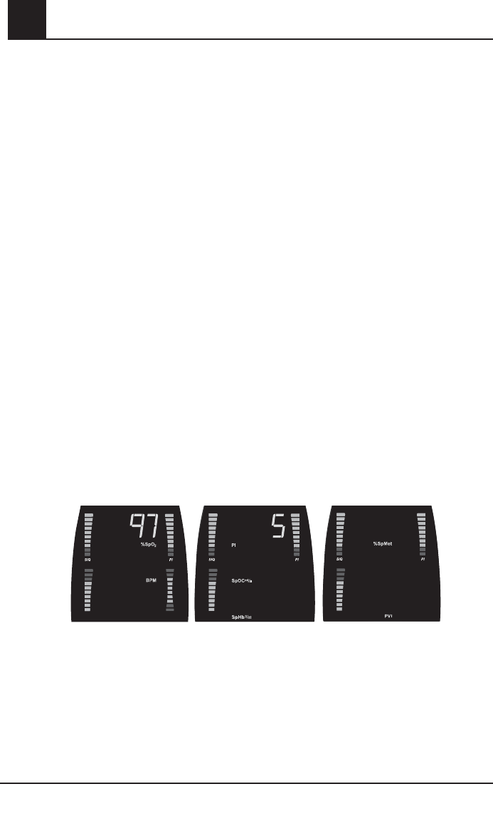
4-16 Rad-87 Pulse CO-Oximeter Operator’s Manual
4Operation
Low Battery Audible Alarm
If a low battery condition occurs the audible alarm can be silenced until power cycle by pressing the
Alarm Silence Button. Refer to Setup Menu Level 2 in this section to change setting.
If a low battery condition occurs while not monitoring a patient, a low priority audible alarm will sound
and can be silenced by pressing the Alarm Silence Button. The audible alarm is silenced until the
power is cycled or patient monitoring begins.While audible alarms are silenced, the first Battery
Level Indicator bar to the left flashes green, and the System Status Light flashes yellow to provide
a visual alert for the user.
When a low battery condition occurs, immediately discontinue patient monitoring and plug the Rad-
87 into AC power. The AC Power Indicator on the Rad-87 illuminates and remains illuminated while
the battery is charging, however, the Battery Charge Level Indicator does not illuminate. Once the
battery is fully charged all Battery Charge Level Indicators illuminate green when unplugged.
During normal patient monitoring, the Battery Charge Bars (Battery Charge Level Indicator) illuminate
green from left to right to indicate the approximate amount of battery charge when unplugged.
CAUTION:
•The battery should be adequately charged to ensure backup power in case of AC
power disruption.
Normal Patient Monitoring
When all optional parameters/measurements are installed, the Rad-87 displays Screen 1 containing
arterial oxygen saturation (%SpO2), pulse rate in beats per minute (BPM) and respiration rate
(RRa)*. By pressing the Display Button once, the display changes to show Screen 2 containing
perfusion index (PI), total arterial oxygen content (SpOC ml/dl)* and total hemoglobin (SpHb g/dl)*.
Pressing the Display Button again changes the display to show Screen 3 containing methemoglobin
(%SpMet)* and carboxyhemoglobin (%SpCO)* and Pleth Variability Index (PVI)*. An additional press
of the Display Button returns the display to Screen 1, the home display screen.
*Optional parameters/measurements: SpCO, SpMet, SpHb, SPOC, PVI, RRa, SIQa, RI
Display Screens showing all Parameters/Measurements -Default Locations
Screen 1
Home display screen
Screen 2 Screen 3
10.1 3
20
%SpCO
1.6
12
13
76
RRa
RISIQa SIQa SIQa
Parameter/Measurement Selection
The bottom field of any display screen may be configured to show RRa, SpHb or PVI (see
Parameter Select menus). Once RRa, SpHb or PVI is configured to show on a screen different
from the default location, the alarm limit menu for RRa, SpHb or PVI can be accessed from the
new screen by pressing the Alarm Limits Button.
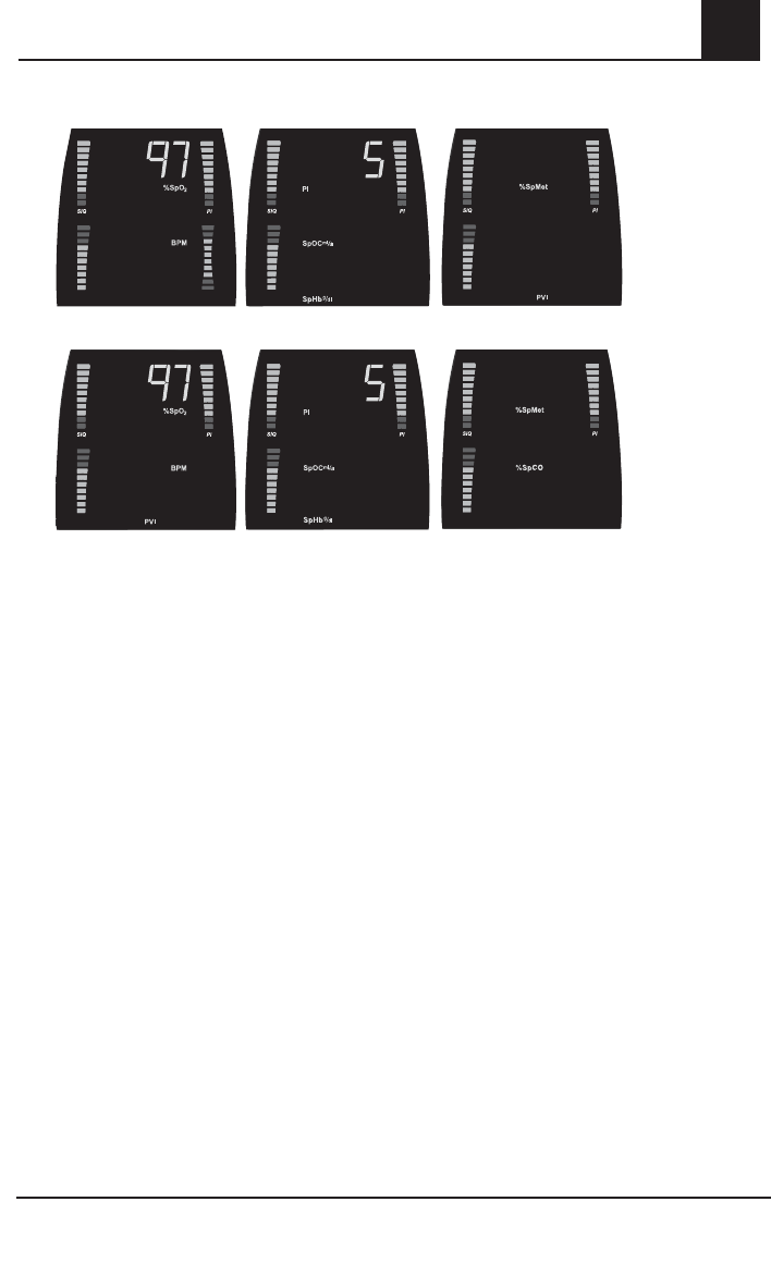
Rad-87 Pulse CO-Oximeter Operator’s Manual 4-17
4
Operation
Display Screens Showing RRa on Screen 1, SpHb on Screen 2 and PVI on Screen 3
10.1 3
20
%SpCO
1.6
12
13
76
RRa
RISIQa SIQa SIQa
Display Screens Showing PVI on Screen 1 and SpHb on Screen 2
Screen 1
Home display screen
Screen 2 Screen 3
3
1.6
10.1
201376
SIQa SIQa SIQa
Setup Menu
This section gives an overview of the Rad-87 menu selections available. To access the menu
levels and navigate through the menu selections, use the front panel buttons, Enter Button and
Up/Down Buttons as indicated in the following sections. Sub-sections describe each menu item
in more detail. The Rad-87 has options that allow user configuration to accommodate specific
needs.
Menu Navigation
The Rad-87 set-up and configuration options are accessed through the menu system. Three
levels of menus are available to the user. Once a menu level is accessed, a front panel button
(Level 1 only) or the Enter Button (Level 2 and 3) is used to move from one option to the next
allowing repeated cycling through the options. The Up and Down Buttons are used to adjust
values within each option. The parameter/measurement value is set when the Enter Button is
pressed. Pressing the Display Button exits the menus and returns the instrument to Screen 1.
When accessing the Rad-87 menu, each selection will be communicated visually on the LED
(front of device) and LCD (top of device) displays, simultaneously.
NOTE: The Rad-87 will automatically ‘time out’ of the setup menu after 30 seconds with no
button presses.
4-18 Rad-87 Pulse CO-Oximeter Operator’s Manual
4Operation
Setup Menu Level 1
Setup Menu Level 1 contains the parameters/measurements and settings that are adjusted most
often for patient monitoring; alarm limits, display brightness, and sensitivity settings. Pressing
the Display Button while viewing alarm limit settings allows the user to exit the Setup Menu and
return to Screen 1.
Parameter/Measurement Alarm Limits - Screen 1
To access alarm limits for parameters/measurements contained on Screen 1, press the Alarm
Limits Button to access the Alarm Limits menu for Screen 1 parameters/measurements.
BUTTONS SETTINGS
Use the Alarm
Limits Button to
access the alarm
limits options and
move between
options.
Press once
%SpO2 LO
Use Up or Down Buttons to adjust the
value to the desired setting
AND
press the Alarm Limits Button or
Enter Button to accept the setting and
move to the next option. Once the
last option is accessed an additional
press of the Alarm Limits Button or
Enter Button will return the instrument
to Screen 1.
OR
press the Display Button to exit at any
time and return to Screen 1.
Press 2x
%SpO2 HI
Press 3x
Pulse rate (BPM) LO
Press 4x
Pulse rate (BPM) HI
Press 5x Respiratory rate
(RRa) LO
Press 6x Respiratory rate
(RRa) HI
NOTE: User default settings can be changed for specific patient environments.
Rad-87 Pulse CO-Oximeter Operator’s Manual 4-19
4
Setup Menu Level 1, continued
Parameter/Measurement Alarm Limits - Screen 2
To access alarm limits for parameters/measurements contained on Screen 2, press the Display
Button to move from Screen 1 to Screen 2. From Screen 2, press the Alarm Limits Button to
access the Alarm Limits menu for Screen 2 parameters/measurements.
BUTTONS SETTINGS
Use the Alarm Limits
Button to access the
alarm limits options and
move between options.
Press once
PI LO Use Up or Down Buttons to adjust
the value to the desired setting
AND
press the Alarm Limits Button or
Enter Button to accept the setting
and move to the next option. Once
the last option is accessed an
additional press of the Alarm Limits
Button will return the instrument to
Screen 2.
OR
press the Display Button to exit at
any time and return to Screen 2.
Press 2x
PI HI
Press 3x
SpHb g/dl LO
Press 4x
SpHb g/dl HI
NOTE: User default settings can be changed for specific patient environments.
Operation
4-20 Rad-87 Pulse CO-Oximeter Operator’s Manual
4Operation
Setup Menu Level 1, continued
Parameter/Measurement Alarm Limits - Screen 3
To access alarm limits for parameters/measurements contained on Screen 3, press the Display
Button two times to move from Screen 1 to Screen 3. Press the Alarm Limits Button from Screen
3 to access the Alarm Limits menu for Screen 3 parameters/measurements.
BUTTONS SETTINGS
Use the Alarm Limits
Button to access the
alarm limits options
and move between
options.
Press once
%SpMet LO
Use Up or Down Buttons to adjust the
value to the desired setting
AND
press the Alarm Limits Button or Enter
Button to accept the setting and move to
the next option. Once the High Pulse rate
limit is accessed an additional press of
the Alarm Limits Button or Enter Button
will return the instrument to Screen 3.
OR
press the Display Button to exit at any time
and return to Screen 3.
Press 2x
%SpMet HI
Press 3x
%SpCO LO
Press 4x
%SpCO HI
Press 5x
PVI LO
Press 6x
PVI HI
NOTE: User default settings can be changed for specific patient environments.
LED Brightness
The Display screen and all active LED indicators are effected while adjusting this setting.
BUTTONS SETTINGS
Use the Brightness But-
ton to access the LED
brightness options and
move between options.
Press once Level 2
(Default)
Use the Brightness Button to move
between menu options and the Enter
Button to accept the setting and return to
the home display screen.
Press 2x
Level 3
Press 3x
Level 4
Press 4x
Level 1
NOTE: User default settings can be changed for specific patient environments.
Rad-87 Pulse CO-Oximeter Operator’s Manual 4-21
4
Setup Menu Level 1, continued
SpO2 Sensitivity
BUTTONS SETTING
Use the SpO2 Sensitiv-
ity Button to access the
sensitivity options and move
between options.
Press once
APOD
(Default)
Use the SpO2 Sensitivity
Button to move between
menu options and accept
the setting.
Press 2x
NORM
Press 3x MAX
(The MAX Indicator
flashes in this
mode.)
Operation
4-22 Rad-87 Pulse CO-Oximeter Operator’s Manual
4Operation
Setup Menu Level 2
Level 2 menu contains parameters and settings that are not changed as frequently as Level 1.
These include alarm volume, alarm delay, clear trend and button volume parameters.
Alarm Volume
BUTTONS SETTINGS
Use the Enter Button
to access the Alarm
Volume menu and to
move between Level
2 menus.
Level 3
(Default)
Use Up or Down Button to move between
settings and the Enter Button to accept
the setting and move to the next menu
screen.
OR
press the Display Button to exit without
saving the new setting and to return to
the home display screen.
Level 4
Level 1
Level 2
SpO2 Alarm Delay
The SpO2 alarm delay allows the user to adjust the time in which the audible status indicator will
occur after a SpO2 alarm condition has been initiated.
BUTTONS SETTINGS
Press the Enter Button
again to move to the
next menu.
2x
5 seconds
(Default)
Use Up or Down Button to move between
settings and the Enter Button to accept the
setting and move to the next menu screen.
OR
press the Display Button to exit without
saving the new setting and to return to the
home display screen.
0 seconds
15 seconds
10 seconds
Rad-87 Pulse CO-Oximeter Operator’s Manual 4-23
4
Operation
Setup Menu Level 2, continued
RRa Alarm Delay
The RRa alarm delay allows the user to adjust the time in which the audible status indicator will
occur after a RRa alarm condition has been initiated.
BUTTONS SETTINGS
Press the Enter Button
again to move to the
next menu.
3x
0
Use Up or Down Button to move between
settings and the Enter Button to accept the
setting and move to the next menu screen.
OR
press the Display Button to exit without
saving the new setting and to return to the
home display screen.
10 seconds
15 seconds
30 seconds
(Default)
60 seconds
Clear Trend
The Rad-87 only stores data in the trend memory while the instrument is turned on. Trend data
saves to the memory until the memory is full or cleared by the user.
NOTE: It is recommended that you clear the trend prior to performing a new patient data
collection procedure.
BUTTON SETTING
Press the Enter Button
again to move to the
next menu.
4x
No
(Default)
Use Up or Down Button to move
between settings and the Enter
Button to accept the setting and move
to the next menu screen.
OR
press the Display Button to exit
without saving the new setting and to
return to the home display screen.
Ye s
(Clear trend)
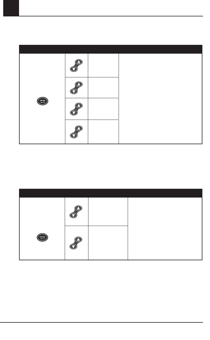
4-24 Rad-87 Pulse CO-Oximeter Operator’s Manual
4Operation
Setup Menu Level 2, continued
Button Volume
BUTTON SETTING
Press the Enter Button
again to move to the
next menu.
5x
Level 2
(Default)
Use Up or Down Button to move between
settings and the Enter Button to accept the
setting and move to the next menu screen.
OR
press the Display Button to exit without
saving the new setting and to return to the
home display screen.
Level 1
Off
Level 3
FastSat
FastSat enables rapid tracking of arterial oxygen saturation changes. Arterial oxygen saturation
data is averaged using pulse oximeter averaging algorithms to smooth the trend. When the Rad-
87 is set to FastSat “On”, the averaging algorithm evaluates all the saturation values providing
an averaged saturation value that is a better representation of the patient’s current oxygenation
status. With FastSat, the averaging time is dependent on the input signal.
BUTTON SETTING
Press the Enter Button
again to move to the
next menu.
6x
Off
(Default)
Use Up or Down Button to move
between settings and the Enter Button
to accept the setting and move to the
Alarm Volume menu.
OR
press the Display Button to exit without
saving the new setting and to return to
the home display screen.
On

Rad-87 Pulse CO-Oximeter Operator’s Manual 4-25
4
Trend Setup and Use
Introduction
The Rad-87 can store up to 72 hours of trend data captured at 2 second intervals. The trend data
can then be transferred to a PC for evaluation. A serial cable is required to connect the Rad-87 to
a PC. Patient monitoring is not possible while trend memory is being transferred to a PC.
Trend data is stored in non-volatile memory, so it is not erased when the instrument is shut off. A
trend data download is initiated using the TrendCom utility which downloads the trend data and
saves it to an ASCII text (.out) file with an output delimiter option.
NOTE: Rad-87 Serial Ouput must be set to ASCII 2 for successful download of trending data.
Refer to the Serial Output menu and settings located farther in this chapter.
NOTE: Rainbow Acoustic Monitoring trending is not available.
TrendCom Utility Installation
Copy the TrendCom utility from the TrendCom CD onto a PC running MS-Windows.
TrendCom Utility Operation
NOTE: Patient monitoring must be suspended while downloading trend data from the
instrument. Ensure the appropriate USB-Serial software driver is installed on the PC,
if using a USB-Serial cable. The PC must have Microsoft Excel spreadsheet software,
or another program capable of opening a .csv (comma separated value) file to view
trend information. Trend information data is limited by the instrument’s parameters.
Download Trend Data from Rad-87
A) Attach the USB-Serial or Serial-Serial Cable
1. Turn the Instrument off.
NOTE: If using a USB-Serial cable, connect the serial cable from the RS-232 serial port on
the back of the instrument to a USB port on the PC. If using a Serial-Serial cable,
connect the cable from the RS-232 serial port on the back of the instrument to a serial
port on the PC.
2. Press firmly to ensure the cable is fully engaged to the instrument.
B) Identify Correct COM Port
NOTE: Instructions provided are for the Windows XP Operating System. To locate the COM
Port in other Operating Systems, please refer to the Operator's Manual for that
Operating System.
1. From the Windows Desktop, click "Start" > "Settings" >"Control Panel" > "System".
2. Click the "Hardware" tab.
3. Click the "Device Manager" button.
4. In the list, find "Ports (COM & LPT)"
5. Click the "+" next to "Ports (COM & LPT)"
6. Find “USB Serial Port” (USB Serial) or “Communications Port” (Serial-Serial). The COM
Port ID number will be to the right of “Communications Port”.
7. Note the COM Port number.
Operation

4-26 Rad-87 Pulse CO-Oximeter Operator’s Manual
4Operation
Trend Setup and Use, continued
C) Start the TrendCom Utility and Initiate Download
1. Turn on the Masimo Rad-87.
2. Make sure the Rad-87 is set to ASCII 2 Output mode.
3. Open the TrendCom Software on the PC.
4. Under the “Instrument” menu in TrendCom, select “Rad-87”.
NOTE: TrendCom will display an “Invalid Data” message if the incorrect instrument is selected.
5. Under the “COM Port” menu, select the appropriate COM Port (ID number from Step B).
6. Click on “Retrieve Trend”.
7. Name the file.
8. Save the file to the appropriate folder. Rad-87 trend information will consist of Date, Time,
SpO2, Pulse Rate and Perfusion Index. Trend information will include Pleth Variability Index,
SpCO, SpMet and/or SpHb, if the parameters are installed.
D) Disconnecting the Cable
1. Turn the instrument off to exit the trend download mode.
2. Disconnect the USB-Serial or Serial-Serial cable from the Instrument and PC.
3. Re-attach the patient cable to the instrument to begin patient monitoring.
NOTE: See the specific cable’s Directions for Use for instructions on attaching the patient
cable to the Instrument
Erasing Trend Memory
The Rad-87 continuously trends data. When performing a new study and gathering data on a
new patient, it is highly recommended the "clear function" be utilized in order for the results to be
separate. Turning the Rad-87 off will not erase the trend data.
1. Press "Enter" until the "CLr trd NO" message is displayed.
2. Press the Up Arrow to display "CLr trd YES".
3. Press "Enter" to display "yES CLr trd" (yes clear trend).
4. Press "Enter" to clear the trend.
5. Press "Display" to return to the main screen.
PARAMETER SPECIFICATION
Date MM\DD\YY
Time HH:MM:SS
Installed Parameter/
Measurement
Numeric value (see the display ranges in the Factory and User
Configurable Default Settings table located at the beginning of this section)
Rad-87
Trend Exception Messages The exceptions are displayed as a hexadecimal value.
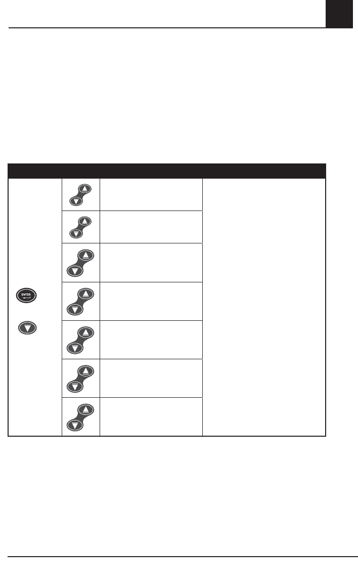
Rad-87 Pulse CO-Oximeter Operator’s Manual 4-27
4
Operation
Setup Menu Level 3
Enter Button + Down Button
The Level 3 menu contains advanced parameter/measurement settings. To access Level 3
parameters/measurements, hold down the Enter Button and press the Down Button for 5
seconds. After entering menu Level 3, use the Enter Button to save new settings and move to
the next menu.
The user may cycle through the menu options by continuing to press the Enter Button. Pressing
the Display Button will exit the menu and return the display to home display screen.
SpO2 Averaging Time
BUTTONS SETTINGS
Hold down
the Enter
Button and
press the
Down Button
for 5 seconds.
+
Press the
Enter Button
again to move
to the next
menu.
8 seconds
(Default)
Use Up or Down Button to move
between settings
AND
press the Enter Button to accept the
setting and move to the next menu
option.
OR
press the Display Button to exit
without saving the new setting and to
return to the home display screen.
4 seconds
2 seconds
16 seconds
14 seconds
12 seconds
10 seconds
(The cycling function for the
menu options is not available.)
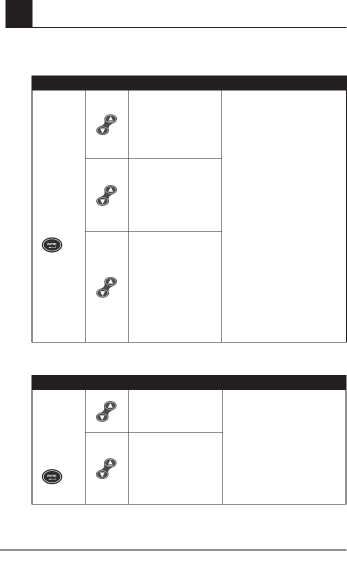
4-28 Rad-87 Pulse CO-Oximeter Operator’s Manual
4Operation
Setup Menu Level 3, continued
SpHb Averaging
BUTTONS SETTINGS
Press the
Enter Button
again to move
to the next
menu.
Short
Use Up or Down Button to move
between settings
AND
press the Enter Button to accept the
setting and move to the next menu
option.
OR
press the Display Button to exit without
saving the new setting and to return to
the home display screen.
Medium
(Default)
Long
PVI Averaging
BUTTONS SETTINGS
Press the
Enter Button
again to move
to the next
menu.
Short
Use Up or Down Button to move
between settings
AND
press the Enter Button to accept the
setting and move to the next menu
option.
OR
press the Display Button to exit
without saving the new setting and to
return to the home display screen.
Long
(Default)
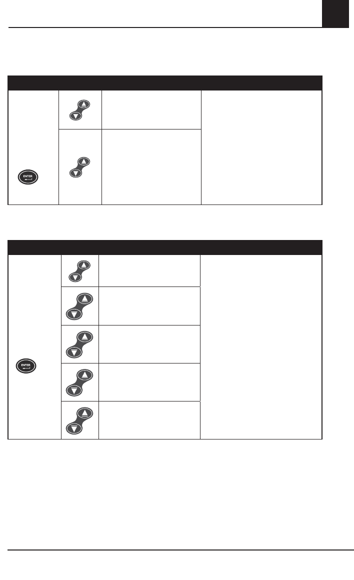
Rad-87 Pulse CO-Oximeter Operator’s Manual 4-29
4
Operation
Setup Menu Level 3, continued
PI Averaging
BUTTONS SETTINGS
Press the
Enter Button
again to
move to the
next menu.
Short
Use Up or Down Button to move
between settings
AND
press the Enter Button to accept the
setting and move to the next menu
option.
OR
press the Display Button to exit
without saving the new setting and to
return to the home display screen.
Long
(Default)
RRa Averaging
BUTTONS SETTINGS
Press the
Enter Button
again to move
to the next
menu.
0
Use Up or Down Button to move
between settings
AND
press the Enter Button to accept the
setting and move to the next menu
option.
OR
press the Display Button to exit
without saving the new setting and to
return to the home display screen.
10 seconds
20 seconds
30 seconds
(Default)
60 seconds
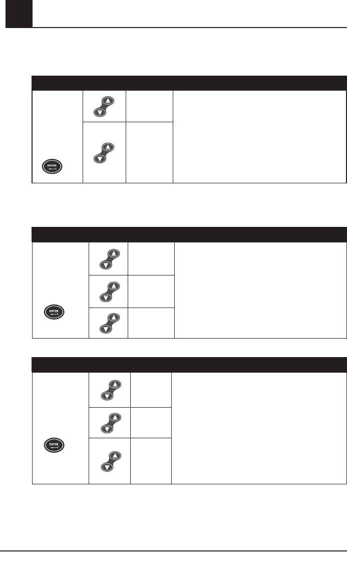
4-30 Rad-87 Pulse CO-Oximeter Operator’s Manual
4Operation
Setup Menu Level 3, continued
RRa Sensor Status Notifications
BUTTONS SETTINGS
Press the
Enter Button
again to
move to the
next menu.
On Use Up or Down Button to move between settings
AND
press the Enter Button to accept the setting and move
to the next menu option.
OR
press the Display Button to exit without saving the new
setting and to return to the home display screen.
Off
(Default)
Rapid Desat Limit
The Rapid Desat Limit is designed to detect rapid desaturations of 5% or 10% below the low
alarm limit and overrides the Alarm Delay feature when activated.
BUTTONS SETTING
Press the Enter
Button again
to move to the
next menu.
5%
(Default)
Use Up or Down Button to move between settings
AND
press the Enter Button to accept the setting and move
to the next menu.
OR
press the Display Button to exit without saving the new
settings and to return to the home display screen.
Off
10%
Alarm On/Off
BUTTONS SETTING
Press the Enter
Button again
to move to the
next menu.
On
(Default) Use Up or Down Button to move between settings
AND
press the Enter Button to accept the setting and move
to the next menu.
OR
press the Display Button to exit without saving the new
setting and to return to the home display screen.
Off
Off rE*
(Alarm
off with
reminder.)
* When Alarm On/Off is set to "Off rE", the audible alarm "beeps" twice every three minutes to remind
the user that the Rad-87 is currently in alarm status but the audible alarm is muted. Visual alarms are
active in this mode. If an alarm limit is violated, the associated parameter/measurement label and value
flash, the alarm bell flashes red for high priority alarms and the System Status Light is solid yellow for
low priority alarms, flashes yellow for medium priority alarms or flashes red for high priority alarms.
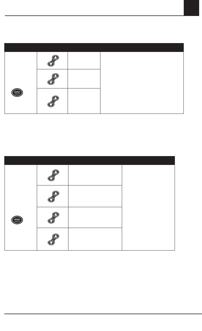
Rad-87 Pulse CO-Oximeter Operator’s Manual 4-31
4
Operation
Setup Menu Level 3, continued
Optical Sensor Off Audible Alarm Latch
BUTTONS SETTING
Press the Enter
Button again
to move to the
next menu.
SEn
Lch
Use Up or Down Button to move between
settings
AND
press the Enter Button to accept the setting
and move to the next menu.
OR
press the Display Button to exit without saving
the new setting and to return to the home
display screen.
On*
Off
(Default)
* Set this option to “On” when it is a requirement for the clinician to go to the instrument bedside and
acknowledge a Sensor Off alarm. Pressing the Alarm Silence Button is required to silence the audible
tone upon correcting the Sensor Off alarm. In the situation where there are valid values after a Sensor
Off alarm has occurred and the instrument is alarming, it is required to press the Alarm Silence Button
to silence the audible tone.
Default Settings
BUTTONS SETTING
Press the Enter
Button again
to move to the
next menu.
No change
(Do not adjust factory
default settings.)
Use Up or Down Button to
move between settings
AND
press the Enter Button
to accept the setting and
move to the next menu.
OR
press the Display Button to
exit without saving the new
setting and to return to the
home display screen.
User Default
(Set to user settings.*)
Factory Default
(Restore factory default
settings.)
Set Device Profile
(One or more pre-defined
instrument profiles)
* Set the Factory Default to this setting when configuring a Device Profile. Refer to the Device Profile
Setup and Use section of this chapter for additional information and instructions.

4-32 Rad-87 Pulse CO-Oximeter Operator’s Manual
4Operation
Setup Menu Level 3, continued
Device Profile Setup and Use
The Rad-87 can be configured to save changes to the instrument settings as a Device Profile.
Using the Rad-87 button menu or an external configuration application, users can adjust Rad-87
settings and parameter/measurement alarm limits. After changing settings, the user may save the
settings as a Device Profile. This Device Profile becomes the new default settings and the saved
(Device Profile) settings will be retained after a power cycle.
To save the settings as a profile from the Rad-87 button menu, the user must enter Setup Menu
Level 3 by pressing and holding the Enter Button and Down Button at the same time for 5
seconds. Then, by pressing the Enter Button three times, the Default Settings screen is displayed.
Press the Up or Down Arrow Button until “User Default – Set” is displayed on the LCD. The user
can press the Enter Button again to save the settings.
Using an external configuration application, the user can save up to five profiles. The user may
select a color for the Device Profile LED to associate with the saved profiles. The Device Profile
LED (located on the front panel of the Rad-87 above the sensor connector) will illuminate with the
selected color, allowing the user to verify at a glance that a Device Profile has been set on the
Rad-87. If changes are made to the instrument settings after the Device Profile feature has been
enabled, the Device Profile LED will turn off until the instrument is returned to the user configured
default settings or powered off, indicating a change from the Device Profile settings.
To set a instrument profile, the user enters Menu Level 3 by pressing and holding the Enter Button
and Down Arrow Button at the same time for 5 seconds. Then, by pressing the Enter Button three
times, the Default Setting screen is displayed. The user can use the Up or Down Arrow Button to
select the desired profile and press the Enter Button to save the setting.
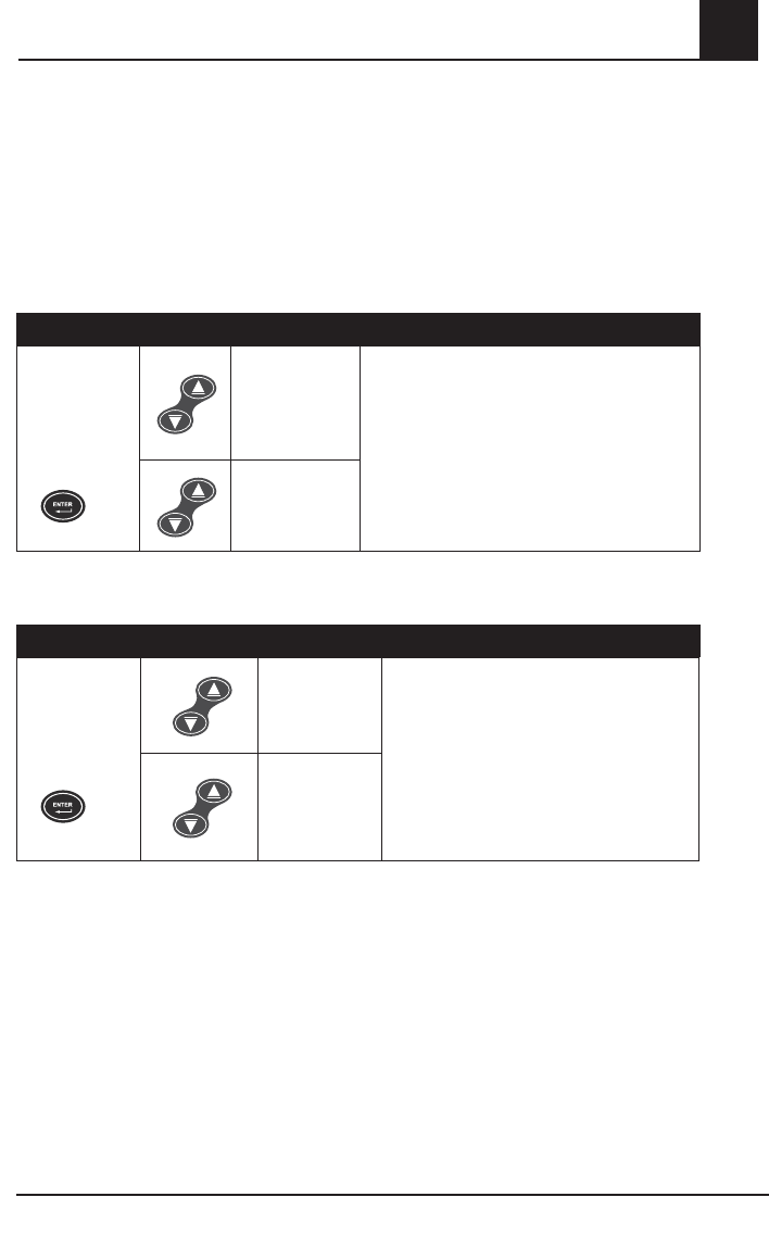
Rad-87 Pulse CO-Oximeter Operator’s Manual 4-33
4
Operation
Setup Menu Level 3, continued
SmartTone On/Off
The SmartTone feature uses a proprietary algorithm that will provide pulse tones during excessive
motion and low perfusion conditions. The pulse tone is based on an averaged pulse rate
measurement from the proprietary algorithm and may not identify irregular heart beat patterns
when there is excessive artifact present. The Normal Tone feature uses a proprietary algorithm
that will provide pulse tones during non motion and adequate perfusion conditions. In this mode,
the pulse tone may not sound if excessive artifact is present.
BUTTONS SETTING
Press the
Enter Button
again to move
to the next
menu.
Off
(Default)
(Normal Tone)
Use Up or Down Button to move between settings
AND
press the Enter Button to accept the setting and
move to the next menu.
OR
press the Display Button to exit without saving
the new setting and to return to the home display
screen.
On
(Smart Tone)
Year
BUTTONS SETTING
Press the Enter
Button again
to move to the
next menu.
Year
Use Up or Down Button to move between settings
AND
press the Enter Button to accept the setting and
move to the next menu.
OR
press the Display Button to exit without saving
the new setting and to return to the home display
screen.
Use Up or Down
Button to adjust
the setting.
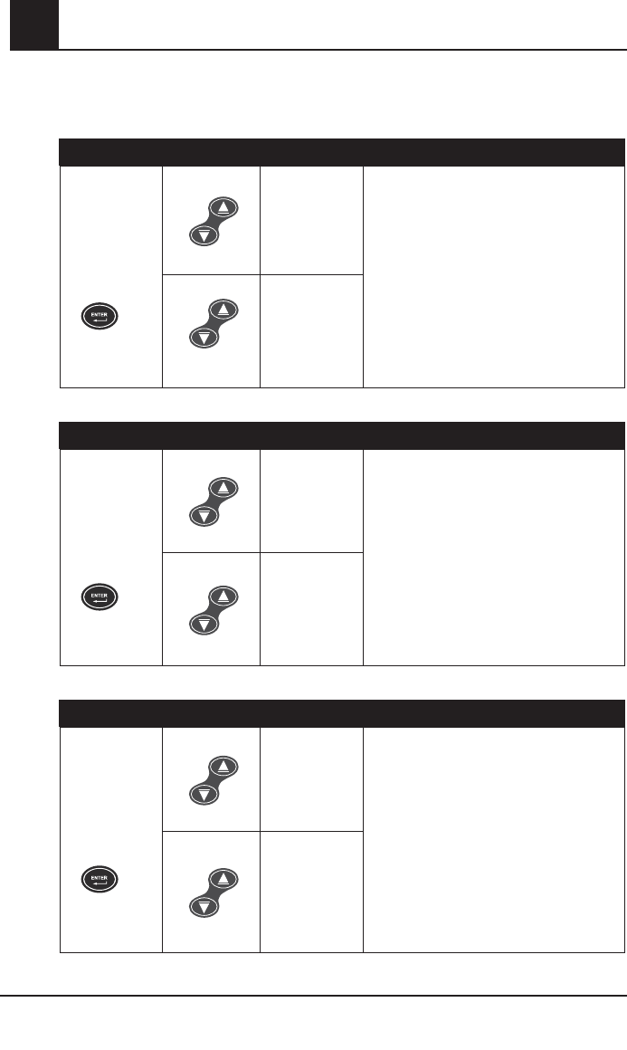
4-34 Rad-87 Pulse CO-Oximeter Operator’s Manual
4Operation
Setup Menu Level 3, continued
Month
BUTTONS SETTING
Press the Enter
Button again
to move to the
next menu
Month
Use Up or Down Button to move between
settings
AND
press the Enter Button to accept the setting
and move to the next menu.
OR
press the Display Button to exit without
saving the new setting and to return to the
home display screen.
Use Up or
Down Button
to adjust the
setting.
Day
BUTTONS SETTING
Press the Enter
Button again
to move to the
next menu.
Day
Use Up or Down Button to move between
settings
AND
press the Enter Button to accept the setting
and move to the next menu.
OR
press the Display Button to exit without
saving the new setting and to return to the
home display screen.
Use Up or
Down Button
to adjust the
setting.
Hour
BUTTONS SETTING
Press the Enter
Button again
to move to the
next menu.
Hour
Use Up or Down Button to move between
settings
AND
press the Enter Button to accept the setting
and move to the next menu.
OR
press the Display Button to exit without
saving the new setting and to return to the
home display screen.
Use Up or
Down Button
to adjust the
setting.
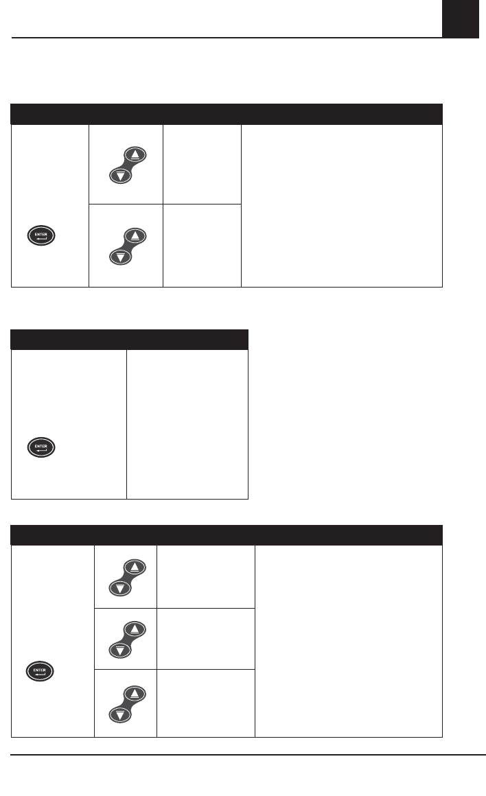
Rad-87 Pulse CO-Oximeter Operator’s Manual 4-35
4
Operation
Setup Menu Level 3, continued
Minute
BUTTONS SETTING
Press the Enter
Button again
to move to the
next menu.
30 minutes
(Default)
Use Up or Down Button to move between
settings
AND
press the Enter Button to accept the setting
and move to the next menu.
OR
press the Display Button to exit without saving
the new setting and to return to the home
display screen.
Use Up or
Down Button
to adjust the
setting.
Software Version
BUTTONS SETTING
Press the Enter Button
again to move to the
next menu
Displays software version.
Serial Output
BUTTONS SETTING
Press the Enter
Button again to
move to the next
menu.
AS2 (ASCII 2)
(Default)
Use Up or Down Button to move between
settings
AND
press the Enter Button to accept the
setting and move to the next menu.
OR
press the Display Button to exit without
saving the new setting and to return to the
home display screen.
AS1 (ASCII 1)
PHL
(Philips Vuelink)
4-36 Rad-87 Pulse CO-Oximeter Operator’s Manual
4Operation
Setup Menu Level 3, continued
Interface Alarms
When Rad-87 is interfaced to another system and the Interface Alarms are set to "Alarm Tones
Off", all parameter audible alarms are muted at the Rad-87 and active at the interfaced system.
This prevents both systems from producing audible alarms at the same time.
NOTE: The Rad-87 reverts to Interface Alarms "Alarm Tones On" during power interruptions or
when the interface connection is lost. This ensures that the Rad-87 provides audible
alarms when connection to the interfaced system becomes compromised.
BUTTONS SETTING
Press the Enter
Button again to
move to the next
menu.
On
(Default)
NOTE: LCD shows
Alarm Tones
On.
Use Up or Down Button to move
between settings
AND
press the Enter Button to accept the
setting and
move to the next menu.
OR
press the Display Button to exit
without saving the new setting and to
return to the home display screen.
Off
NOTE: LCD shows
Alarm Tones
Off.
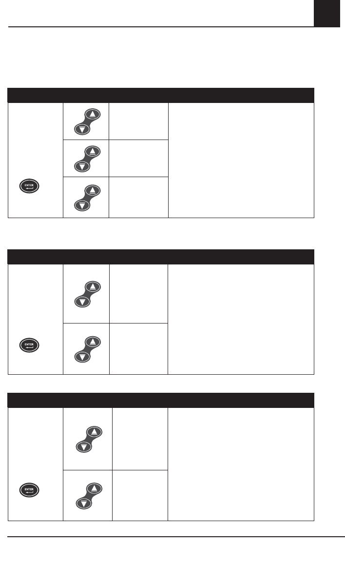
Rad-87 Pulse CO-Oximeter Operator’s Manual 4-37
4
Operation
Setup Menu Level 3, continued
Nurse Call
Refer to Section 7, Nurse call specifications for additional information.
BUTTONS SETTING
Press the Enter
Button again
to move to
the next menu
option.
Alarm
(Default)
Use Up or Down Button to move between
settings
AND
press the Enter Button to accept the setting
and move to the next menu option.
OR
press the Display Button to exit without saving
the new setting and to return to the home
display screen.
Signal I.Q.
Alarm and
Signal I.Q.
Polarity
Refer to Section 7, Nurse Call Specifications for additional information.
BUTTONS SETTING
Press the Enter
Button again
to move to
the next menu
option.
Normal
(Default)
Use Up or Down Button to move between
settings
AND
press the Enter Button to accept the setting
and move to the next menu option.
OR
press the Display Button to exit without saving
the new setting and to return to the home
display screen.
Inverse
Line Frequency
BUTTONS SETTING
Press the Enter
Button again
to move to
the next menu
option.
60
(Default)
Use Up or Down Button to move between
settings
AND
press the Enter Button to accept the setting
and move to the next menu option.
OR
press the Display Button to exit without saving
the new setting and to return to the home
display screen.
50
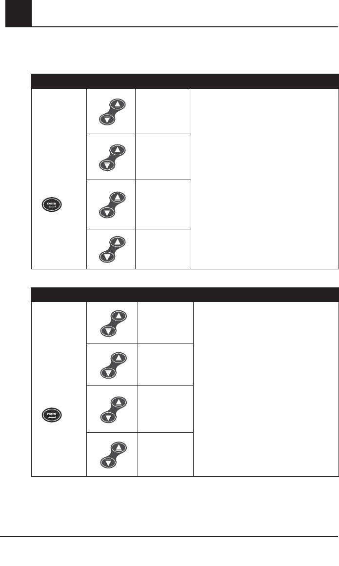
4-38 Rad-87 Pulse CO-Oximeter Operator’s Manual
4Operation
Setup Menu Level 3, continued
Parameter/Measurement Select - Screen 1
BUTTONS SETTING
Press the Enter
Button again
to move to
the next menu
option.
RRa
(if available)
Use Up or Down Button to move between
settings
AND
press the Enter Button to accept the setting and
move to the next menu option.
OR
press the Display Button to exit without saving
the new setting and to return to the home
display screen.
SpHb
(if available)
PVI
(if available)
(no parameter/
measurement
displayed)
Parameter/Measurement Select - Screen 2
BUTTONS SETTING
Press the Enter
Button again
to move to
the next menu
option.
RRa
(if available)
Use Up or Down Button to move between
settings
AND
press the Enter Button to accept the setting
and move to the next menu option.
OR
press the Display Button to exit without saving
the new setting and to return to the home
display screen.
SpHb
(if available)
PVI
(if available)
(no parameter/
measurement
displayed)
Rad-87 Pulse CO-Oximeter Operator’s Manual 4-39
4
Operation
Setup Menu Level 3, continued
Parameter/Measurement Select - Screen 3
BUTTONS SETTING
Press the Enter
Button again
to move to
the next menu
option.
RRa
(if available) Use Up or Down Button to move between
settings
AND
press the Enter Button to accept the setting
and move to the next menu option.
OR
press the Display Button to exit without saving
the new setting and to return to the home
display screen.
SpHb
(if available)
PVI
(if available)
(no parameter/
measurement
displayed)
SpHb Precision
BUTTONS SETTING
Press the Enter
Button again
to move to
the next menu
option.
Hb Pcn 0.1
(Default)
Use Up or Down Button to move between
settings
AND
press the Enter Button to accept the setting
and move to the next menu option.
OR
press the Display Button to exit without saving
the new setting and to return to the home
display screen.
0.1, 0.5, 1
SpHb Calculation
BUTTONS SETTING
Press the Enter
Button again
to move to
the next menu
option.
Hb CAL Art
(Default)
(Arterial)
Use Up or Down Button to move between
settings
AND
press the Enter Button to accept the setting
and move to the next menu option.
OR
press the Display Button to exit without saving
the new setting and to return to the home
display screen.
Hb CAL VEn
(Venous)
4-40 Rad-87 Pulse CO-Oximeter Operator’s Manual
4Operation
Setup Menu Level 3, continued
LCD Language
BUTTONS SETTING
Press the Enter
Button again
to move to
the next menu
option.
English
(Default)
Use Up or Down Button to move between
settings
AND
press the Enter Button to accept the setting
and move to the next menu option.
OR
press the Display Button to exit without saving
the new setting and to return to the home
display screen.
Scrolls through
available
languages
displayed on
the LCD
SpHb Display
BUTTONS SETTING
Press the Enter
Button again to
return to first
menu option.
Hb dPL No
(Default)
Use Up or Down Button to move between
settings
AND
press the Enter Button to accept the setting
and return to first menu option.
OR
press the Display Button to exit without saving
the new setting and to return to the home
display screen.
No (display
dashes),
Yes (Display
SpHb value)
Enter Button + Up Button
Set Mode
BUTTONS SETTING
Hold down the
Enter Button
and press the
Up Button for 5
seconds.
+
Standard
(Default)
Use Up or Down Button to move between
settings
AND
press the Enter Button to accept the setting.
OR
press the Display Button to exit without saving
the new setting and to return to the home
display screen.
Sleep Mode*
Home Mode
*CAUTION:
•Alarms are disabled in this mode.

Rad-87 Pulse CO-Oximeter Operator’s Manual 4-41
4
Operation
Home Mode Operation
The Rad-87 can be placed into the Home Mode to protect unqualified users from changing the
Rad-87 alarm settings and operation. Only the following menu and front panel functions are
available: display brightness, pulse beep volume adjustment and alarm silence. Alarm volume is
at highest setting. All default and user defined default settings are locked to their current values
when home mode is selected and return to those values after a power cycle. Upon power up,
the Hnn mode will be displayed along with a 10 second display of parameters/measurements. To
turn the instrument off the Power Button must be depressed and held for 3 seconds. The Enter
and Up Buttons held simultaneously for 5 second will put it back into the special menu to select
a different mode.
Sleep Mode Operation
The Rad-87 can be placed into the Sleep Mode to allow the instrument to capture normal and
abnormal patient data without triggering the alarms. This mode will blank out the LED and the
LCD Displays with the exception of the AC Power Indicator, the System Status Light, and the
Battery Level Indicator and disables the alarms even after a power cycle. However, pressing
any button illuminates the display and the System Status Light (solid yellow) for 10 seconds.
Upon power up, the SLP mode will be displayed along with a 10 second display of parameter/
measurement settings. The Enter and Up Buttons held simultaneously for 5 seconds will put it
back into the special menu to select a different mode.
CAUTION:
•Alarms are disabled in this mode.
Brightness Button + Down Button
Access the Enable/Disable Radio menu by holding down the Brightness and Down Buttons for
5 seconds.
Enable/Disable Radio
BUTTONS SETTING
Hold down the
Brightness Button
and press the Down
Button for 5 seconds.
+
Off
(Default)
Use Up or Down Button to move between
settings
AND
press the Enter Button to accept the setting
and exit to the home display screen.
On

4-42 Rad-87 Pulse CO-Oximeter Operator’s Manual
4Operation
LCD Display Function with Radio Configured and Enabled
When the Radio feature is enabled (set to "On") and configured with the required network
information, the LCD Display shows the following information for 20 seconds:
■Network Mode
■Radio Mode
■Channel
■SSID
■IP address
■Subnet
■Gateway
■MAC Address
■Encryption
■Authentication
■Destination IP
■Destination Port
■Signal Strength
■Connected Access Point
■Radio Diagnostics
■Radio Error
■Error 1
■Error 2
■Error 3
■Error 4

Rad-87 Pulse CO-Oximeter Operator’s Manual 5-1
5
Alarms and Messages
g
Alarm Identification
The Rad-87 identifies alarms visually and audibly based on alarm conditions that the system
detects. The 'system' includes the instrument, cables and sensors. Alarm conditions that occur
depend upon the parameters monitored on the patient. Audible alarms will continue to sound
until a valid parameter value is displayed on the instrument. The Rad-87 alarms are categorized
into the following: Alarm Limit Alarms, System Monitoring Alarms, System Function Alarms,
Instrument Errors/Warnings and RRa Sensor Status Notifications.
■ Parameter Threshold Alarms occur when a patient's measurement exceeds the parameter
threshold setting in the instrument.
■ System Monitoring Alarms occur when the sensor from a channel is off the patient or a
sensor and/or cable is disconnected. Examples include Sensor Off or No Cable.
■ System Function Alarms occur when a component in the signal path fails or the parameter
is not installed on the instrument. An example would be Incompatible Sensor.
■ Instrument Error/Warning Alarms occur when there are instrument hardware issues.
Examples include a hardware error code or a low battery.
The Alarm Category Table below details the Rad-87 alarms by alarm category and channel.
Alarm Category Table
CATEGORY CHANNEL ALARM
Parameter Threshold
Alarms
Optical
High SpO2
Low SpO2
High SpCO
Low SpCO
High PI
Low PI
High Pulse Rate
Low Pulse Rate
High SpMet
Low SpMet
High PVI
Low PVI
High SpHb
Low SpHb
Acoustic High RRa
Low RRa
System Monitoring
Alarms
Optical
Sensor Off No Adhesive
No Sensor No Cable
Acoustic
Sensor Off
No Sensor No Cable

5-2 Rad-87 Pulse CO-Oximeter Operator’s Manual
5
Alarm Category Table, continued
CATEGORY CHANNEL ALARM
System Function
Alarms
Optical
Incompatible
Sensor
Replace
Sensor Sen 000
Incompatible
Adhesive
Replace
Adhesive Adh 000
Incompatible
Cable
Replace
Cable Cbl 000
Interference
Detected
Acoustic
Incompatible
Sensor
Replace
Sensor Sen 000
Incompatible
Cable
Replace
Cable Cbl 000
Instrument
Error/Warning Alarms N/A Err ## Low Battery
RRa Sensor Status
Notifications Acoustic No Sensor Interference
Detected
NOTE: There are no alarms associated with SpOC.
Alarm Limits
CAUTION:
•To ensure that alarm limits are appropriate for the patient being monitored, check
the limits each time the Rad-87 is used.
NOTE: The following alarm limits may be set to "---": High SpO2, High SpCO, Low SpCO, High
SpMet, Low SpMet, High SpHb, Low SpHb, High PI, Low PI High PVI and Low PVI.
When the setting of "---" is made on the instrument, the alarm limit is disabled.
NOTE: The low alarm limit must always be set below the high alarm setting. Attempting to
set the high alarm limit below the low alarm limit, the low alarm limit will automatically
adjust the low limit to the next setting below the newly entered high alarm limit setting.
NOTE: Pressing and holding down the up and down buttons allow for the rapid scrolling of
changing alarm limits.
NOTE: If there is a loss of power for any length of time, the Alarm settings will be set back
to the User set defaults. If the user has not utilized this option, then all parameters/
measurements will be set back to the factory defaults.
Alarms and Messages

Rad-87 Pulse CO-Oximeter Operator’s Manual 5-3
5
Alarm Limit: User Configurable Settings
SETTING FACTORY
DEFAULT RANGE INCREMENTS
High SpO2 Limit "---" Off 2% - 99% 1%
Low SpO2 Limit 90% 1% - 98%1%
High Pulse Rate Limit 140 BPM 35 BPM - 235 BPM 5 BPM
Low Pulse Rate Limit 50 BPM 30 BPM - 230 BPM 5 BPM
High SpCO Limit 10 2% - 98% 1%
Low SpCO Limit "---" Off 1% - 97% 1%
High SpMet Limit 31% - 99.5% 0.1% for values 0.1% - 2%
0.5% for values 2% - 99.5%
Low SpMet Limit "---" Off 0.1% - 99% 0.1% for values 0.1% - 2%
0.5% for values 2% - 99.5%
High SpHb Limit 17 2 g/dl - 24.5 g/dl 0.1 g/dl for values 2 g/dl - 20 g/dl
0.5 g/dl for values 20 g/dl - 24.5 g/dl
Low SpHb Limit 71 g/dl - 24 g/dl 0.1 g/dl for values 0.1 g/dl - 20 g/dl
0.5 g/dl for values 20 g/dl - 24 g/dl
High PI Limit "---" Off 0.04% - 19%
0.01% for values 0.02% - 0.1%
0.1% for values 0.1% - 1%
1% for values 1% - 19%
Low PI Limit "---" Off 0.03% - 18%
0.01% for values 0.03% - 0.1%
0.1% for values 0.1% - 1%
1% for values 1% - 18%
High PVI Limit "---" Off 2% - 99% 1%
Low PVI Limit*"---" Off 1% - 98% 1%
High RRa Limit
(breaths per minute) 30 5 - 69 breaths per
minute 1 breath per minute
Low RRa Limit
(breaths per minute) 64 - 68 breaths per
minute 1 breath per minute
Alarms and Messages

5-4 Rad-87 Pulse CO-Oximeter Operator’s Manual
5Alarms and Messages
Alarm Priorities
The Rad-87 has three levels of alarm priority implemented: high, medium and low. The alarm
priorities reflect how the instrument will behave when an alarm is present. The following table
outlines instrument attributes within the alarm priorities.
ALARMS
INSTRUMENT ATTRIBUTES
SYSTEM
STATUS
LIGHT
PARAM-
ETER
VALUE
PARAM-
ETER
LABEL
ALARM
BELL
AUDIBLE
TONE
High
Low SpO2
Flashing Red
Flashing Flashing
Flashing
Red
Active
High pulse rate
Low pulse rate
High SpCO
High SpMet
High SpHb
Low SpHb
High RRa
Low RRa
Sensor Off, No Sensor,
Incompatible Sensor or
Adhesive, Replace Sensor,
Adhesive, or Reusable,
SEN 000, Adh 000
No cable, Incompatible
Cable, Replace Cable,
Cbl 000
Instrument failures
Medium
High SpO2
Flashing
Yellow
Off
High PI
Low PI
High PVI
Low PVI
Low battery, monitoring
patient
Low
Low SpCO
Solid Yellow
Low SpMet
Low battery, not monitoring
patient

Rad-87 Pulse CO-Oximeter Operator’s Manual 5-5
5
Alarms and Messages
The Rad-87 offers the ability to monitor multiple 'channels' on a patient. The Rad-87 has an
optical based channel and an acoustic based channel. The optical based channel provides
SpO2, pulse rate, SpCO, SpMet, SpHb, SpOC, PI and PVI. The acoustic based channel provides
respiration rate (RRa). When both the optical and acoustic channels are monitoring the patient
together, the optical channel is considered 'primary' and the acoustic 'secondary'.
NOTE: SpO2 monitoring is required when monitoring RRa (Acoustic Respiration).
NOTE: When both the optical and acoustic channels are present and the RRa Sensor Status
Notifications are set to 'Off', the RRa Sensor Status Notifications do NOT activate an
audible tone. Refer to the Alarm Category Table earlier in this section for the RRa
Sensor Status Notifications.
Multiple Parameter/Measurement Alarms
When multiple parameters/measurements alarm, the screen with the highest alarm priority (and
with a parameter/measurement in alarm status) will show on the display. Refer to the table Alarm
Priority for Display Screens located below.
Additional parameters/measurements in alarm status (competing alarms) that are not contained
on the active screen will show as flashing parameter/measurement labels (names). The
parameters/measurements with competing alarms can be viewed by pressing the Display Button
to scroll through the screens. When an alarm is resolved, the parameter/measurement label
stops flashing. When all parameters/measurements in alarm status on a display screen are
resolved, the screen changes to show the next priority screen with active alarms.
Alarm Priority for Display Screens
PRIORITY DISPLAY SCREEN PARAMETERS/MEASUREMENTS SHOWN
1 Screen 1 %SpO2, BPM, RRa
2Screen 2 PI, SpHb, %SpOC
3Screen 3 %SpMet, %SpCO, PVI
The display screens are assigned alarm priority according to the table above. Screen 1 has
first priority and displays if it contains a parameter/measurement in alarm status with other
competing parameter/measurement alarms. When Screen 2 contains the competing parameter/
measurement alarms, Screen 2 will take priority and show on the display. Screen 3 has the
lowest priority.
Alarm Silence

5-6 Rad-87 Pulse CO-Oximeter Operator’s Manual
5
Audible alarms may be silenced, while visual alarms remain active. The alarm silence function
is controlled by pressing the Alarm Silence button. The Alarm Bell and the System Status Light
provide visual feedback when the Rad-87 audible alarms are silenced.
When monitoring a patient with both the optical and acoustic channels present
Action: Alarm event occurs; press Alarm Silence button once (audible alarms silenced for
configured Alarm Silence period. Default is 120 seconds.)
ALARM PRIORITY ALARM BELL SYSTEM STATUS LIGHT
High Flashing Red Flashing Red
Medium Off Flashing Yellow
Low Off Off
Action: Press Alarm Silence button a second time during Alarm Silence period
State: Audible alarms become active
Action: Removal of an optical patient cable/sensor
State: Alarm active
ALARM PRIORITY ALARM BELL SYSTEM STATUS LIGHT
High Flashing Red Flashing Red
Action: Press Alarm Silence button
State: Alarms silenced
ALARM PRIORITY ALARM BELL SYSTEM STATUS LIGHT
Any Off Solid Yellow
Action: Removal of an acoustic patient cable/sensor
State: Alarm active
ALARM PRIORITY ALARM BELL SYSTEM STATUS LIGHT
High Flashing Red Flashing Red
Action: Press Alarm Silence
State: Alarms silenced
ALARM PRIORITY ALARM BELL SYSTEM STATUS LIGHT
Any Off Solid Green
Alarms and Messages

Rad-87 Pulse CO-Oximeter Operator’s Manual 5-7
5
Alarms and Messages
Action: Removal of both patient cables/sensors
State: Alarms active
ALARM PRIORITY ALARM BELL SYSTEM STATUS LIGHT
High Flashing Red Flashing Red
Action: Press Alarm Silence button
State: Alarms silenced
ALARM PRIORITY ALARM BELL SYSTEM STATUS LIGHT
Any Off Solid Yellow
When not monitoring a patient
Action: Press Alarm Silence button
State: Alarms silenced
ALARM PRIORITY ALARM BELL SYSTEM STATUS LIGHT
Low Off Solid Yellow
this State remains until active patient monitoring begins.
Alarm Bell
The Alarm Bell flashes red for high priority alarms. Pressing the Alarm Silence Button once
silences the audible alarm for 120 seconds (default) while the Alarm Bell flashes to indicate an
alarm condition. If the high priority alarm condition is resolved during the Alarm silence interval,
the Alarm Bell stops flashing. If the high priority alarm condition remains (Alarm Bell flashing
red), pressing the Alarm Silence button again activates the audible alarms and the Alarm Bell
continues to flash red. The Alarm Bell stops flashing when the high priority alarm conditions are
resolved.
System Status Light
While monitoring a patient and an alarm condition occurs, an audible alarm activates and the
System Status Light shows solid yellow for low priority alarms, flashes yellow for medium priority
alarms or flashes red for high priority alarms. Pressing the Alarm Silence Button (one time)
silences the alarm tone for 120 seconds (default). Pressing the Alarm Silence Button a second
time activates the audible alarms and the System Status Light shows solid yellow for low priority
alarms, flashes yellow for medium priority alarms or flashes red for high priority alarms. When all
alarm conditions are resolved, the System Status Light changes to solid green.
While not monitoring a patient, the System Status Light illuminates solid yellow. If an alarm
condition occurs the System Status Light shows solid yellow for low priority alarms. Pressing the
Alarm Silence Button will permanently silence the alarm tone and the System Status Light is solid
yellow until the power is cycled or patient monitoring begins.
Should the alarm condition be created by a low battery condition, plug the instrument into AC
power immediately.

5-8 Rad-87 Pulse CO-Oximeter Operator’s Manual
5Alarms and Messages
Alarm Mute
When the Rad-87 is set to Interface Alarms "Alarm Tones Off" and an alarms condition occurs,
the Alarm Bell flashes red and the System Status Light is solid yellow for low priority alarms,
flashes yellow for medium priority alarms or flashes red for high priority alarms. The audible
alarm activates at the interfaced system while the audible alarm is muted at the device. Once the
alarm condition is resolved and there are no other system or parameter/measurement alarms,
the Alarm Bell stops flashing, the System Status Light changes to solid green and the audible
alarm at the interfaced system deactivates.
NOTE: An audible alarm will accompany the visual indicators unless the Rad-87 has been set
to Interface Alarms "Alarm Tones Off" or to Sleep Mode (all alarms muted).
NOTE: The Rad-87 reverts to Interface Alarms "Alarm Tones On" during power interruptions
or when the interface connection is lost. This ensures that the Rad-87 provides audible
alarms when connection to the interfaced system becomes compromised.
NOTE: Audible Alarm Tones are not active in the multiparameter patient monitor when used
with the VueLink interface. Refer to the Philips VueLink Setup section for details.

Rad-87 Pulse CO-Oximeter Operator’s Manual 5-9
5
Alarms and Messages
Messages
The Rad-87 Pulse CO-Oximeter will indicate other data or system errors. LED messages for
the optical channel occupy the top two LED segments on the instrument. LED messages for the
acoustic channel occupy the third LED segment.
Message conditions for the Rad-87 follow:
MESSAGE/DISPLAY POSSIBLE CAUSE(S) RECOMMENDATION(S)
LCD: Replace
Sensor
LED: SEN
Hrs
000
SpHb reusable sensor is non-
functional. Replace sensor.
LCD: Replace
Sensor
LED: Rpl
SeN
Sensor is non-functional.
Emitter temperature out of
range.
Sensor current limit exceeded.
Replace sensor.
LCD: Incompatible
Sensor
LED: IN C
SeN
Unrecognized sensor.
Not a compatible Masimo
sensor.
Replace with a compatible
Masimo sensor. Refer to Section 8.
SpHb Sensor is attached to
an instrument without SpHb
installed.
Use a non-SpHb sensor.
Contact your local Masimo
Representative to learn more
about the optional SpHb upgrade.
LCD: Sensor Calibrating
LED: The number “0” scrolls
across the screen during
sensor calibration when not
actively monitoring a patient
Status Light: Solid Yellow
(Long Calibration Only)
Instrument is checking the
sensor for proper functioning
and performance.
If values are not displayed within
30 seconds, disconnect and
reconnect sensor. If values are still
not displayed, replace with a new
sensor.
LCD: Sensor Off
LED:
SeN
OFF
Sensor off patient. Reconnect sensor.
LCD: Latched
Sensor Off
LED:
SeN (or valid values)
OFF
Optical Sensor Off Audible Alarm
Latch is set to 'On'.
The Alarm Silence button
has not been pressed to
acknowledge the Sensor Off
alarm.
Reapply the sensor according to
the sensor’s Directions for Use.
Press the Alarm Silence button
to acknowledge the Sensor Off
alarm.

5-10 Rad-87 Pulse CO-Oximeter Operator’s Manual
5Alarms and Messages
MESSAGE/DISPLAY POSSIBLE CAUSE(S) RECOMMENDATION(S)
LCD: No Sensor
LED:
NO
SeN
No sensor connected. Connect sensor to patient.
LCD: Check
Sensor
LED:
CHc
SEN
Sensor is not connected
firmly into patient cable or the
instrument.
Reconnect sensor firmly into
patient cable, or to the instrument.
LCD: No Adhesive
Reconnect*
LED:
NO
AdH*
When using the Masimo
ReSposable Sensor System, the
adhesive part is not connected.
Connect the ReSposable adhesive
to the ReSposable reusable
sensor.
LCD: Replace
Adhesive*
LED:
AdH
000*
When using the Masimo
ReSposable Sensor System, the
adhesive part is non-functional.
Replace the ReSposable adhesive
of the sensor system.
LCD: Invalid
Adhesive*
LED:
IN C
ADH*
When using the Masimo
ReSposable Sensor System, the
adhesive part is incompatible or
unrecognized.
Replace the ReSposable adhesive
of the sensor system.
LCD: Replace
Adhesive*
LED:
Rpl
AdH*
When using the Masimo
ReSposable Sensor System,
the adhesive portion is non-
functional.
Replace the ReSposable adhesive
of the sensor system.
LCD: Replace
Reusable*
LED:
Rpl
REu*
When using the Masimo
ReSposable Sensor System,
the resuable sensor is non-
functional.
Replace the ReSposable
resusable sensor of the sensor
system.
LCD: Replace
Cable
LED:
rPL
CBL
The patient cable is non-
functional. Replace the patient cable.
LCD: Replace
Cable
LED:
CBL
000
Cable is non-functional. Replace cable.
* Messages do not apply to Masimo Rainbow R Series Adhesive Sensors

Rad-87 Pulse CO-Oximeter Operator’s Manual 5-11
5
Alarms and Messages
MESSAGE/DISPLAY POSSIBLE CAUSE(S) RECOMMENDATION(S)
LCD: No Cable
LED:
NO
CBL
No cable is connected. Reconnect cable.
LCD: Invalid
Cable
LED:
IN C
CBL
Incompatible or unrecognized
cable.
Connect appropriate cable to
instrument.
LCD: Interference Detected
(Optical Channel)
LED:
Int
DEt
Improperly applied sensor. Reapply the sensor according to
the sensor’s Directions for Use.
High intensity light such as
pulsating strobe lights, excessive
ambient light sources such as
surgical lights or direct sunlight,
or other monitor displays.
Place a Masimo Optical Light
Shield over the sensor.
Incorrect monitor line frequency
setting (Hz).
Adjust the Line Frequency to the
correct Hz setting as described in
Section 4.
LCD: Interference Detected
(Acoustic Channel)
LED:
Int
DEt
Improperly applied sensor. Reapply the sensor according to
the sensor’s Directions for Use.
Excessive ambient or
environmental noise.
Identify and remove the excessive
ambient or environmental noise.
LCD: RR Invalid
SpO2 not avail
LED: "--" (RRa parameter)
There are no valid SpO2 values.
Apply a sensor to obtain valid
SpO2 values, according to the
sensor's Directions for Use.
LCD: System Fault
LED: Err
##
There are several error codes.
All errors codes require returning
the instrument to an authorized
service center for repair.
Return for service. Refer to
Section 9, Service and Repair.
LCD: SpO2 Only Mode
“SpO2 Only Mode” message
occurs during an unsuccessful
sensor calibration/pulse search
routine, or during monitoring.
Refer to: the sensor’s Directions
for Use, Section 4, Successful
Monitoring, and Section 8,
Selecting a Masimo SET Sensor.
Scrolling Zeros Pulse search.
Wait for found pulse. This search
should occur whenever a sensor is
first applied to a patient.
Pulse Bar (SIQ) Turns Red Low Signal I.Q. Rule out occusion of blood flow.
Verify placement of sensor.

5-12 Rad-87 Pulse CO-Oximeter Operator’s Manual
5
MESSAGE/DISPLAY POSSIBLE CAUSE(S) RECOMMENDATION(S)
Bottom Two Segments of
Perfusion Bar (PI) are Red Low Perfusion.
Rule out occusion of blood flow.
Attempt to warm patient.
Move sensor to better perfused site.
NOTE: Masimo recommends using an
adhesive sensor whenever low perfu-
sion is expected or evident.
Parameter/Measurement Label
and Number Flash Alarm Limit Exceeded.
Assess/address patient condition.
Reset alarms limits, if indicated.
Refer to Section 4 for instructions.
Single Battery Level Indicator
Flashes (With Audible Alarm) Battery level too low. Connect instrument to AC power
to charge the battery.
Alarms and Messages

Rad-87 Pulse CO-Oximeter Operator’s Manual 6-1
6
Troubleshooting
g
Troubleshooting
The following chart describes what to do if the Rad-87 system does not operate properly.
PROBLEM POSSIBLE CAUSE(S) RECOMMENDATION(S)
Instrument does
not power on
Low battery/ not plugged into
AC power supply.
Connect the AC power cord to the Rad-87 and to an AC
outlet. Make sure that the AC power indicator light is on.
Battery run-time
Is significantly
reduced
Low battery Contact Technical Services or your local Masimo
representative.
Continuous
Speaker Tone Internal Failure.
Instrument requires service. Press the Alarm Silence
button. If alarm continues to sound, power down device. If
the power button does not turn the instrument off, press
and hold the power button for 5 seconds.
Return the instrument for service.
No Speaker
Tone Pulse tone set to “mute”. Press Up arrow or Alarm Volume adjust.
No Alarm Tone Alarm Silence Enabled. The System Status Light flashes yellow. See Section 4,
Alarm Silence.
Buttons fail
to work when
pressed
Internal Failure.
Use auxilary power down method by pressing and
holding Sensitivity and Display buttons simultaneously.
Return for service.
No Sensor
message
Sensor is disconnected from
patient cable.
Sensor connected upside
down into patient cable.
Check to see if the sensor LED is flashing. Disconnect
and reconnect the sensor. If the LED fails to operate,
replace the sensor.
Low Perfusion
(PI Bar Turns
Red)
Improper sensor type.
Poorly perfused site.
Sensor is too tight. A disorder
such as hypothermia,
vasoconstriction, hypovolemia,
peripheral vascular disease
or anemia.
Sensor is damaged.
Verify proper sensor and sensor size for the patient.
Check and see if blood flow to the site is restricted. Be
sure that the sensor is not on too tight.
Set unit to MAX sensitivity.
Warm the patient or sensor site.
Move sensor to better perfused site.
Low SIQ
Improper sensor type or
application.
Excessive motion relative to
perfusion.
Sensor or cable is damaged
or not functioning.
Check and see if blood flow to the site is restricted.
Check the placement of the sensor.
Re-apply sensor or move to a different site.
Replace sensor or cable.

6-2 Rad-87 Pulse CO-Oximeter Operator’s Manual
6Troubleshooting
PROBLEM POSSIBLE CAUSE(S) RECOMMENDATION(S)
Low SIQa and
flashing RRa
parameter*
Low confidence in RRa
value (Last confident value
displayed).
May occur during patient
activity (e.g. talking).
Check for proper sensor placement.
Reduce patient activity. Reduce excessive ambient or
environmental noise.
Low RI
Improperly applied sensor.
Patient may have shallow
breathing.
Assess the patient.
SpO2 values do
not correlate with
clinical assess-
ment Or abgs.
Low perfusion or sensor
displacement.
Check for error messages. See section 5 Messages for
recommended corrections
Check placement of sensor or if it is too tight. Reapply
sensor or select a new site.
Set to MAX sensitivity and confirm that the sensor is
securely on the patient
Refer to sensor's Directions For Use.
Pulse Search
message
Instrument is searching for
pulse.
If instrument fails to display within 30 seconds,
disconnect and reconnect sensor to patient. If pulse
search continues, move sensor to better perfused site.
Unexpected SpO2,
SpCO, SpMet Or
SpHb reading
Low SIQ or Perfusion Index (PI)
values.
Reposition sensor to site with strong SIQ and PI. Submit
blood sample for laboratory CO-Oximetry test for
comparison.
Inappropriate sensor size or
sensor measurement location.
Verify proper sensor for patient size. Verify proper sensor
site.
Unexpected High
SpCO reading
Possible elevated
methemoglobin level. Submit blood sample for laboratory CO-Oximetry test.
Difficulty Or No
SpO2/SpCO/
SpMmet/SpHb
reading
Low battery/ not plugged into
AC power supply.
Connect the AC power cord to the Rad-87 and to an AC
outlet. Make sure that the AC power indicator light is on.
Excessive motion. Minimize or eliminate motion at the monitoring site.
Interference from line-frequency
induced noise.
Verify/set 50/60Hz menu setting. See section 3, Rad-87
Power Requirements.
Inappropriate sensor or sensor
size. Verify proper sensor and sensor size for the patient.
Excessive ambient or strobing
light. Shield the sensor from excessive or strobing light.
Also, see Section 4, Successful Monitoring for additional information.
Print Function
does not work Wrong serial cable is used. Make sure a null modem cable is used.
Wireless Radio
no connection
Radio off. Confirm the wireless radio is on.
Network settings are not
configured correctly. Confirm wireless network settings.
No/inadequate wireless
coverage. Confirm wireless coverage.
* If a confident RRa value has not been detected after 5 minutes, the RRa value will display as double dashes (- -) and
an audible alarm will become active. This will occur if the acoustic channel is the primary channel and also when RRa
Sensor Status Notifications are set to 'On'.

Rad-87 Pulse CO-Oximeter Operator’s Manual 7-1
7
Specifications
p
Rad-87 Specifications
PERFORMANCE
Measurement Range
SpO2: 0 -100%
SpMet: 0 - 99.9%
SpCO: 0 - 99%
SpHb 0 - 25 g/dl
SpOC 0 - 35 ml of O2/dl of blood
Pulse Rate: 25 - 240 (bpm)
RRa (Respiration Rate): 0 - 70 breaths per minute
SIQa 0% - 100%
Perfusion Index: 0.02% - 20%
Pleth Variability Index: 0 - 100%
Accuracy:
Arterial Oxygen Saturation Accuracy1
Saturation 60% to 80%
No Motion
Adults, Infants, Pediatrics ±3%
Saturation 70% to 100%
No Motion2
Adults, Infants, Pediatrics ± 2%
Neonates* ± 3%
Motion3
Adults, Infants, Pediatrics, Neonates ± 3%
Low Perfusion4
Adults, Infants, Pediatrics, Neonates ± 2%
Pulse Rate Accuracy5
Pulse Rate: 25 - 240 (bpm)
No Motion
Adults, Infants, Pediatrics, Neonates ± 3 bpm
Motion3
Adults, Infants, Pediatrics, Neonates ± 5 bpm
Low Perfusion4
Adults, Infants, Pediatrics, Neonates ± 3 bpm
Carboxyhemoglobin saturation accuracy (%SpCO)1
Adults, Infants, Pediatrics 1% - 40% ± 3%
Methemoglobin saturation accuracy (%SpMet)1
Adults, Infants, Pediatrics, Neonates 1% - 15% ± 1%
Total Hemoglobin accuracy (SpHb g/dl)9
Adults, Pediatrics 8 - 17 g/dl ±1 g/dL
Respiratory Rate Accuracy (RRa, breaths per minute)10
Adults 4 to 70 ± 1 breath per minute
Resolution
Arterial Oxygen Saturation (%SpO2)1%
Carboxyhemoglobin Saturation (%SpCO) 1%
Methemoglobin Saturation (%SpMet) 0 .1%
Total Hemoglobin (SpHb g/dl) 0 .1 g/dl

7-2 Rad-87 Pulse CO-Oximeter Operator’s Manual
7
Respiration Rate (RRa) 1 breath per minute
Pulse Rate (bpm) 1 bpm
* Only Rainbow sensors provide ± 2% for Neonates
ELECTRICAL
AC Power requirements: 100 - 240 VAC, 47-63 Hz
Power consumption: 20 VA max.
Batteries
Type: Sealed lead acid
Capacity (battery life)6:
Rad-87 (stand-alone) up to 3 hours
Rad-87 with Rainbow Acoustic Monitoring up to 2 hours
Rad-87 with wireless radio and Rainbow Acoustic Monitoring up to 1 hour
Charging time: minimum 8 hours
ENVIRONMENTAL
Operating Temperature: 32°F to 122°F (0°C to 50°C)
Transport/Storage Temperature: -40°F to 158°F (-40°C to +70°C)7
Operating Humidity: 10% to 95%, non-condensing
Operating Altitude: 500 mbar to 1060 mbar pressure
-1000 ft to 18,000 ft (-304 m to 5,486 m)
PHYSICAL CHARACTERISTICS
Dimensions: 8.2” x 6.0” x 3.0” (20.8 cm x 15.2cm x 7.6 cm)
Weight: 2.1 lbs. = .908 Kg. = 32 oz
Trending
72 hours of trending at 2 second resolution (Rainbow Acoustic Monitoring trending is not available)
Mode
SpO2 Averaging mode: 2, 4, 8,10, 12, 14 or 16 seconds8
SpO2 Sensitivity: Normal, Maximum9, and APOD
RRa Averaging mode: 0, 10, 20, 30, 60 seconds
Alarms
Audible and visual alarms for high low saturation and pulse rate (SpO2 range 1% - 99%, SpCO range 1% - 98%,
SpMet range 1% - 99.5%, SpHb range1 g/dl - 24.5 g/dl, RRa range 4 - 70 breaths per minute, PI range 0.03% -
19%, PVI range 1% - 99%, pulse rate range 30 - 235 BPM)
Sensor condition, system failure and low battery alarms
High Priority Audible Alarm: 800 Hz tone, 5 pulse burst, pulse spacing: 0.250s,
0.250s, 0.500s, 0.250s, repeat time:10s
Medium Priority Audible Alarm 500 Hz tone, 3 pulse burst, repeat time: 5s
Low Priority Audible Alarm: 500 Hz tone, 3 pulse burst, repeat time: 5s
Alarm Volume High: 85 dB (min)
Low: 45 dB (min)
High Priority Visual Alarm: Red flashing 2 sec. (0-5 Hz)
Medium Priority Visual Alarm Yellow flashing 4 sec (0.25 Hz)
Low Priority Visual Alarm: Solid yellow
Specifications

Rad-87 Pulse CO-Oximeter Operator’s Manual 7-3
7
Specifications
Display/Indicators
Type: LED
Display Language English (default)
Data display: %SpO2, %SpCO, %SpMet, SpHb g/dl, SpOC ml/dl, pulse rate, pleth variability index (PVI), RRa,
alarm status, status messages, Signal I.Q. (SIQ), acoustic Signal I.Q. (SIQa), perfusion index
(PI),Respiration Indicator (RI), sensitivity modes, wireless radio connection, system status light.
Display update rate: 1 second
Output Interface
Serial RS-232
Wireless Radio (if installed) 802.11 a/b/g
Nurse Call
Philips VueLink, RadNet, Patient SafetyNet
Compliance
Safety Standard for Medical Equipment IEC 60601-1 2nd Edition
IEC 60601-2-49 1st Edition
UL 60601-1
CAN/CSA C22.2 No. 601-1
JIS 0601-1
Type of Protection Class 1 (AC power), Internally powered (battery power)
Degree of Protection-(Pulse CO-Oximeter Cable): Type BF, Defib Proof Applied-Part
Mode of Operation: Continuous
EMC Standard EN 60601-1-2
Wireless Radio (if installed)
Compatibility Standard 802.11 a/b/g
USA FCC ID VKF-Rad87
FCC Parts 15.247 and 15.407
Canada IC ID 7362A-Rad87
RSS-210
Europe EN 300328, EN 301893, EN 301489-17
1 SpO2, SpCO and SpMet accuracy was determined by testing on healthy adult volunteers in the range 60% - 100% SpO2, 0% - 40% SpCO and
0% - 15% SpMet against a laboratory CO-Oximeter. SpO2 and SpMet accuracy was determined on 16 neonatal NICU patients ranging in age
from 7 to 135 days old and weighting between 0.5 and 4.25 kgs. Seventy-nine (79) data samples were collected over a range of 70 - 100% SaO2
and 0.5 - 2.5% HbMet with a resultant accuracy of 2.9% SpO2 and 0.9% SpMet. Contact Masimo for testing specifications.
2 The Masimo sensors have been validated for no motion accuracy in human blood studies on healthy adult male and female volunteers with light to
dark skin pigmentation in induced hypoxia studies in the range of 70-100% SpO2 against a laboratory CO-Oximeter and ECG monitor. This variation
equals plus or minus one standard deviation. Plus or minus one standard deviation encompasses 68% of the population.
3
The Masimo sensors have been validated for motion accuracy in human blood studies on healthy adult male and female volunteers with light to dark skin
pigmentation in induced hypoxia studies while performing rubbing and tapping motions, at 2 to 4 Hz at an amplitude of 1 to 2 cm and a non-repetitive
motion between 1 to 5 Hz at an amplitude of 2 to 3 cm in induced hypoxia studies in the range of 70-100% SpO2 against a laboratory CO-Oximeter and
ECG monitor. This variation equals plus or minus one standard deviation. Plus or minus one standard deviation encompasses 68% of the population.
4 The Rad-87 has been validated for low perfusion accuracy in bench-top testing against a Fluke Biotek Index 2 simulator and Masimo's simulator with
signal strengths of greater than 0.02% and transmission of greater than 5% for saturations and pulse rates within the stated accuracy specifications.
This variation equals plus or minus one standard deviation. Plus or minus one standard deviation encompasses 68% of the population.
5 Masimo sensors have been validated for pulse rate accuracy for the range of 25-240 bpm in bench top testing against a Biotek Index 2 simulator.
This variation equals plus or minus one standard deviation which encompasses 68% of the population.
6 This represents approximate run time at the lowest indicator brightness and pulse tone turned off using a fully charged battery.
7 If the batteries are to be stored for extended periods of time, it is recommended that they be stored between -20°C to +30°C, and at a relative
humidity less than 85%. If stored for a prolonged period at environmental conditions beyond these limits, overall battery capacity may be diminished,
and lifetime of the batteries may be shortened.
8 With FastSat the averaging time is dependent on the input signal. For the 2 and 4 second settings the averaging time may range from 2-4 and 4-6
seconds, respectively.
9. SpHb accuracy has been validated on healthy adult male and female volunteers and on surgical patients with light to dark skin pigmentation in the
range of 8 g/dL to 17 g/dL SpHb against a laboratory CO-Oximeter. The variation equals plus or minus one standard deviation which encompasses
68% of the population. The SpHb accuracy has not been validated with motion or low perfusion.
10.
Respiration rate accuracy for the Masimo Acoustic Respiration Sensor and Instrument has been validated for the range of 4 to 70 breaths per minute in
bench top testing. Clinical validation for up to 30 breaths per minute was also performed with the Masimo Acoustic Respiration Sensor and Instrument.

7-4 Rad-87 Pulse CO-Oximeter Operator’s Manual
7
Serial Interface Specifications
The digital interface for serial communication is based on the standard RS-232 protocol. The
Rad-87 Pulse CO-Oximeter by default always outputs ASCII 1 text data through the serial port,
unless the user selects a different output mode in the Output menu. To interface with the Rad-87
and receive serial text data, simply connect a serial interface cable with a serial output connector
located on the back of the Rad-87.
NOTE: Trend data packets are collected at 2 second intervals. Each data packet contains: the
date, time, SpO2, perfusion index, SpMet, SpCO, SpHb, PI, pulse rate, and alarm and
exception values (in ASCII 2 format).
Serial Interface Setup
To interface with the Rad-87 serial port, set the following communication parameters on the
interfacing serial device:
PARAMETER SETTING
Baud Rate 9600 Baud bidirectional
Number of bits per character 8
Parity None
Bits 1 start, 1 stop
Handshaking None
Connector type Female DB-9
The pin-outs for the RS-232 connector are shown in the following table:
PIN SIGNAL NAME
1No Connection
2Receive data – RS-232 ±9 V (±5 Vmin)
3Transmit data – RS-232 ±9 V (±5 Vmin)
4No Connection
5Signal Ground Reference for COM signals
6No Connection
7No Connection
8No Connection
9No Connection
Serial Printer Setup
To print the SpO2 and pulse rate data in ASCII 2 format on a serial printer, simply connect the
serial printer to the serial port and set output mode to ASCII 2. Once serial communication is
established, the Rad-87 will automatically start printing the ASCII 2 text data.
WARNING: ALL EXTERNAL DEVICE CONNECTIONS TO THE RS-232 SERIAL PORT
MUST BE IEC-60950 COMPLIANT.
Specifications

Rad-87 Pulse CO-Oximeter Operator’s Manual 7-5
7
Nurse Call Specifications
The nurse call features are accessible via the 1/4” round female connector on the back of the
device.
Nurse Call
The nurse call feature on the Rad-87 Pulse CO-Oximeter is based on the relay closing or opening
depending on alarm, Low Signal I.Q. events or both. In addition the nurse call polarity can be
inverted to accommodate various nurse call stations requirements.
The nurse call relays have the following electrical specification per switch:
PARAMETER SPECIFICATION
Max Voltage 36 VDC or 24 VAC peak
WARNING: THE NURSE CALL FEATURE IS DISABLED WHEN THE AUDIBLE ALARMS
ARE SILENCED AND NURSE CALL SETTING IS SET TO “ALARMS”.
Specifications


Rad-87 Pulse CO-Oximeter Operator’s Manual 8-1
8
Sensors & Patient Cables
Introduction
This section covers the use and cleaning of Masimo sensors and patient cables. Before use
of any sensor, carefully read the sensor’s Directions for Use. Use only Masimo sensors and
cables with the Rad-87 Pulse CO-Oximeter. Other transducers, sensors and cables may affect
Rad-87's performance.
Tissue damage can be caused by incorrect application or use of a sensor, for example by
wrapping the sensor too tightly. Inspect the sensor site as directed in the sensor's Directions for
Use to ensure skin integrity, correct positioning and adhesion of the sensor.
CAUTIONS:
•Do not use damaged sensors or patient cables. Do not use a sensor or patient cable
with exposed optical or electrical components.
•Do not immerse the sensor or patient cable in water, solvents, or cleaning solutions
(the sensors and connectors are not waterproof).
•Unless otherwise specified, do not sterilize sensors or patient cables by irradiation,
steam, autoclave or ethylene oxide. See the cleaning instructions in the directions
for use for reusable Masimo sensors.
•Do not attempt to reprocess, recondition or recycle any Masimo sensors or patient
cables as these processes may damage the electrical components, potentially
leading to patient harm.
•All sensors and cables are designed for use with specific monitors. Verify the
compatibility of the monitor, cable and sensor before use, otherwise patient injury
can result.
•To avoid damage to the cables, always hold the cable by the connector rather than
the cable when connecting or disconnecting either end.
Selecting a Masimo SET Sensor
When selecting a sensor, consider the patient’s weight, the adequacy of perfusion, the available
sensor sites, and the duration of monitoring. For more information refer to the following tables
or contact your Sales Representative. Use only Masimo sensors and sensor cables. Select an
appropriate sensor, apply it as directed, and observe all warnings and cautions presented in the
Directions for Use accompanying the sensor. Monitor, cables and sensors must be compatible
to ensure optimal performance. Incompatible components affect operation or data recovery.
High intensity extreme lights (such as pulsating strobe lights) directed on the Pulse CO-Oximeter
sensors, may not allow the sensor to obtain measurements. Excessive ambient light sources such
as surgical lights (especially those with a xenon light source), bilirubin lamps, fluorescent lights,
infrared heating lamps, and direct sunlight, as well as other monitor displays can interfere with
the performance of the sensor. To prevent interference from ambient light, ensure that the sensor
is properly applied, and cover the sensor site with a Masimo Optical Light Shield. Failure to take
this precaution in excessive ambient light conditions may result in inaccurate measurements.
Sensor Application Instructions
Unless indicated otherwise in the directions for use, reposition reusable sensors at least every 4
hours and for adhesive sensors inspect the site at least every 8 hours or sooner. If indicated by
circulatory condition or skin integrity, reapply to a different monitoring site.
p

8-2 Rad-87 Pulse CO-Oximeter Operator’s Manual
8Sensors & Patient Cables
Masimo Acoustic Respiration Sensor
Acoustic Respiration Sensor, Acoustic Respiration Patient Cable and Dual Rainbow
Cable
The Acoustic Respiration Sensor and Rainbow acoustic cables are indicated for continuous,
noninvasive monitoring of respiration rate (RRa) for adult patients, in hospitals, hospital-type
facilities, mobile and home environments.
Sensor Weight Range Breaths per Minute, Accuracy Range
RAS-125 Adult > 30 kg 4 to 70 ± 1 breath per minute
Masimo Rainbow Sensors
Rainbow sensors will only measure SpO2 and pulse rate on devices without Masimo Rainbow
SET Technology.
Rainbow Reusable Sensors
SpO2, SpMet, SpHb and pulse rate accuracy for the Rainbow sensors is specified in the following
table.
Rainbow reusable sensors must be used in conjunction with Rainbow RC cables.
Sensor Weight
Range
Saturation Accuracy Pulse Rate
Accuracy
Low Perfusion
Accuracy
SpMet
Accuracy
SpHb
Accuracy
No Motion Motion No
Motion Motion Saturation Pulse
Rate No Motion
DCI > 30 kg 60 - 80 ± 3%
70 -100 ± 2% ± 3% ± 3 bpm ± 5 bpm ± 2% ± 3 bpm ± 1% ± 1 g/dl
DCIP 10 - 50 kg 60 - 80 ± 3%
70 -100 ± 2% ± 3% ± 3 bpm ± 5 bpm ± 2% ± 3 bpm ± 1% ± 1 g/dl
Rainbow Direct Connect Sensors
SpO2, SpCO, SpMet and pulse rate accuracy for the Rainbow sensors is specified in the
following table.
Rainbow Direct Connect sensors connect to the instrument directly.
Sensor Weight
Range
Saturation Accuracy Pulse Rate
Accuracy
Low Perfusion
Accuracy
SpCO
Accuracy
SpMet
Accuracy
No Motion Motion No
Motion Motion Saturation Pulse
Rate No Motion No Motion
DCI-dc3
DCI-dc8
DCI-dc12
> 30 kg 60 - 80 ± 3%
70 -100 ± 2% ± 3% ± 3 bpm ± 5 bpm ± 2% ± 3 bpm ± 3% ± 1%
DCIP-dc3
DCI-dc8
DCIP-dc12
10 - 50 kg 60 - 80 ± 3%
70 -100 ± 2% ± 3% ± 3 bpm ± 5 bpm ± 2% ± 3 bpm ± 3% ± 1%

Rad-87 Pulse CO-Oximeter Operator’s Manual 8-3
8
Sensors & Patient Cables
SpO2, SpMet, SpHb and pulse rate accuracy for the Rainbow sensors is specified in the following
table.
Rainbow Direct Connect sensors connect to the instrument directly.
Sensor Weight
Range
Saturation Accuracy Pulse Rate
Accuracy
Low Perfusion
Accuracy
SpMet
Accuracy SpHb
Accuracy
No Motion Motion No
Motion Motion Saturation Pulse
Rate No Motion
DC-3
DC-12 > 30 kg 60 - 80 ± 3%
70 -100 ± 2% ± 3% ± 3 bpm ± 5 bpm ± 2% ± 3 bpm ± 1% ± 1 g/dl
DCP-3
DCP-12 10 - 50 kg 60 - 80 ± 3%
70 -100 ± 2% ± 3% ± 3 bpm ± 5 bpm ± 2% ± 3 bpm ± 1% ± 1 g/dl
Rainbow R Series Adhesive Sensors
SpO2, SpCO, SpMet and pulse rate accuracy for the Rainbow sensors is specified in the following
table.
Rainbow adhesive sensors must be used in conjunction with Rainbow RC cables.
Sensor Weight
Range
Saturation Accuracy Pulse Rate Accuracy Low Perfusion
Accuracy
SpCO
Accuracy
SpMet
Accuracy
No Motion Motion No
Motion Motion Saturation Pulse
Rate
No
Motion No Motion
R25
> 30 kg 60 - 80% ± 3%
70 - 100% ± 2% ± 3% ± 3 bpm ± 5 bpm ± 2% ± 3 bpm ± 3% ± 1%
R25-L
> 30 kg 60 - 80% ± 3%
70 - 100% ± 2% ± 3% ± 3 bpm ± 5 bpm ± 2% ± 3 bpm ± 3% ± 1%
< 3 kg* 70 - 100% ± 2% ± 3% ± 3 bpm ± 5 bpm ± 2% ± 3 bpm N/A ± 1%
R20
10 - 50 kg 60 - 80% ± 3%
70 - 100% ± 2% ± 3% ± 3 bpm ± 5 bpm ± 2% ± 3 bpm ± 3% ± 1%
R20-L
3 - 10 kg 60 - 80% ± 3%
70 - 100% ± 2% ± 3% ± 3 bpm ± 5 bpm ± 2% ± 3 bpm ± 3% ± 1%
10 - 30 kg 60 - 80% ± 3%
70 - 100% ± 2% ± 3% ± 3 bpm ± 5 bpm ± 2% ± 3 bpm ± 3% ± 1%
SpO2, SpMet, SpHb and pulse rate accuracy for the Rainbow sensors is specified in the following
table.
Rainbow adhesive sensors must be used in conjunction with Rainbow RC cables.
Sensor Weight
Range
Saturation Accuracy Pulse Rate Accuracy Low Perfusion
Accuracy
SpMet
Accuracy
SpHb
Accuracy
No Motion Motion No Motion Motion Saturation Pulse
Rate No Motion No Motion
R1 25
R1 25L
> 30 kg 60 - 80% ± 3%
70 - 100% ± 2% ± 3% ± 3 bpm ± 5 bpm ± 2% ± 3 bpm ± 1% 1 g/dL
R1 20
10 - 50 kg 60 - 80% ± 3%
70 - 100% ± 2% ± 3% ± 3 bpm ± 5 bpm ± 2% ± 3 bpm ± 1% 1 g/dL
R1 20-L
3 - 10 kg 60 - 80% ± 3%
70 - 100% ± 2% ± 3% ± 3 bpm ± 5 bpm ± 2% ± 3 bpm ± 1% 1 g/dL
10 - 30 kg

8-4 Rad-87 Pulse CO-Oximeter Operator’s Manual
8
Rainbow ReSposable™ Pulse CO-Oximeter Sensor System
SpO2, SpMet, SpHb and pulse rate accuracy for the Rainbow sensors is specified in the following
table.
The R2-25a must be used with a R2-25r and the R2-20a must be used with a R2-20r.
Sensor Weight
Range
Saturation
Accuracy
Pulse Rate
Accuracy
Low Perfusion Accuracy SpMet
Accuracy
SpHb
Accuracy
Saturation Pulse Rate
R2-25a
R2-25r
> 30 kg
60 - 80% ± 3%
70 - 100% ± 2%
± 3 bpm ± 2% ± 3 bpm ± 1% ± 1 g/dl
R2-20a
R2-20r
10 - 50 kg
60 - 80% ± 3%
70 - 100% ± 2%
± 3 bpm ± 2% ± 3 bpm ± 1% ± 1 g/dl
Masimo SpO2 Sensors
Masimo SpO2 sensors measure arterial saturation and pulse rate.
ReSposable™ Pulse CO-Oximeter Sensor System
The S2-25a must be used with a S2-25r and the S2-20a must be used with a S2-20r.
Sensor Weight Range Saturation Accuracy
Pulse Rate
Accuracy Low Perfusion Accuracy
Saturation Pulse Rate
S2-25a
S2-25r
> 30 kg
60 - 80% ± 3%
70 - 100% ± 2%
± 3 bpm ± 2% ± 3 bpm
S2-20a
S2-20r
10 - 50 kg
60 - 80% ± 3%
70 - 100% ± 2%
± 3 bpm ± 2% ± 3 bpm
Red Direct Connect Sensors
Red sensors will only function with CO-Oximeter devices equipped with Masimo Rainbow SET
technology.
Red Direct Connect sensors connect to the instrument directly.
Sensor Weight Range Saturation Accuracy Pulse Rate Accuracy Low Perfusion Accuracy
No Motion Motion No Motion Motion Saturation Pulse Rate
Red DCI-dc3
Red DCI-dc12
> 30 kg ± 2% ± 3% ± 3 bpm ± 5 bpm ± 2% ± 3 bpm
Red DCIP-dc3
Red DCIP-dc12
10 - 50 kg ± 2% ± 3% ± 3 bpm ± 5 bpm ± 2% ± 3 bpm
Sensors & Patient Cables
Rad-87 Pulse CO-Oximeter Operator’s Manual 8-5
8
LNOP® Reusable Sensors
LNOP reusable sensors must be used in conjunction with PC or Red PC cables.
Sensor Weight Range Saturation Accuracy Pulse Rate Accuracy Low Perfusion Accuracy
No Motion Motion No Motion Motion Saturation Pulse Rate
LNOP DCI > 30 kg ± 2% ± 3% ± 3 bpm ± 5 bpm ± 2% ± 3 bpm
LNOP DCIP 10 - 50 kg ± 2% ± 3% ± 3 bpm ± 5 bpm ± 2% ± 3 bpm
LNOP YI > 1 kg ± 2% ± 3% ± 3 bpm ± 5 bpm N/A N/A
LNOP TC-I > 30 kg ± 3.5% N/A ± 3 bpm N/A ± 3.5% ± 3 bpm
LNOP DC-195 > 30 kg ± 2% ± 3% ± 3 bpm ± 5 bpm ± 2% ± 3 bpm
LNOP TF-I > 30 kg ± 2% N/A ± 3 bpm N/A ± 2% ± 3 bpm
NOTE: The LNOP TF-I and TC-I sensors were not validated under motion conditions.
LNOPv™ Adhesive Sensors
LNOPv adhesive sensors must be used in conjunction with PC or Red PC cables.
Sensor Weight Range Saturation Accuracy Pulse Rate Accuracy Low Perfusion Accuracy
No Motion Motion No Motion Motion Saturation Pulse Rate
LNOPv In 3 - 20 kg ± 2% ± 3% ± 3 bpm ± 5 bpm ± 2% ± 3 bpm
LNOPv Ne < 3 kg ± 3% ± 3% ± 3 bpm ± 5 bpm ± 3% ± 3 bpm
LNOPv Ad > 30 kg ± 2% ± 3% ± 3 bpm ± 5 bpm ± 2% ± 3 bpm
LNOP Specialty Sensors
LNOP specialty sensors must be used in conjunction with PC or Red PC cables.
Sensor Range
No Motion Motion No Motion Motion Saturation Pulse Rate
LNOP Newborn Infant 3 - 30 kg ± 2% ± 3% ± 3 bpm ± 5 bpm ± 2% ± 3 bpm
Infant 10 - 30 kg ± 3% ± 3% ± 3 bpm ± 5 bpm ± 3% ± 3 bpm
LNOP Newborn
Neonatal < 3 kg ± 3% ± 3% ± 3 bpm ± 5 bpm ± 3% ± 3 bpm
LNOP Trauma > 30 kg ± 2% ± 3% ± 3 bpm ± 5 bpm ± 2% ± 3 bpm
LNOP Blue 2.5 - 30 kg
60 - 80% ± 4% N/A ± 3 bpm N/A ± 3% ± 3 bpm
70 - 100% ± 3.3% N/A ± 3 bpm N/A ± 3% ± 3 bpm
80 - 100% ± 3% N/A ± 3 bpm N/A ± 3% ± 3 bpm
M-LNCS™/LNCS® Reusable Sensors
M-LNCS sensors must be used in conjuction with M-LNC or Rainbow patient cables or M-LNC
adapter cables.
LNCS reusable sensors must be used in conjunction with LNC or Red LNC cables.
Sensor
M-LNCS/LNCS DCI > 30 kg ± 2% ± 3% ± 3 bpm ± 5 bpm ± 2% ± 3 bpm
M-LNCS/LNCS DCIP 10 - 50 kg ± 2% ± 3% ± 3 bpm ± 5 bpm ± 2% ± 3 bpm
M-LNCS/LNCS TC-I > 30 kg ± 3.5% N/A ± 3 bpm N/A ± 3.5% ± 3 bpm
M-LNCS/LNCS TF-I > 30 kg ± 2% N/A ± 3 bpm N/A ± 2% ± 3 bpm
M-LNCS/LNCS YI > 1 kg ± 2% ± 3% ± 3 bpm ± 5 bpm N/A N/A
Sensors & Patient Cables

8-6 Rad-87 Pulse CO-Oximeter Operator’s Manual
8Sensors & Patient Cables
NOTE: The M-LNCS/LNCS TF-I and TC-I sensors were not validated under motion conditions.
M-LNCS™/LNCS® Adhesive Sensors
M-LNCS sensors must be used in conjuction with M-LNC or Rainbow patient cables or M-LNC
adapter cables.
LNCS sensors must be used in conjunction with LNC or Red LNC cables.
Sensor Weight
Range
Saturation Accuracy Pulse Rate Accuracy Low Perfusion Accuracy
No Motion Motion No Motion Motion Saturation Pulse Rate
M-LNCS/LNCSAdtx
M-LNCS/LNCSAdtx-3 > 30 kg ± 2% ± 3% ± 3 bpm ± 5 bpm ± 2% ± 3 bpm
M-LNCS/LNCS Pdtx
M-LNCS/LNCS Pdtx-3 10 - 50 kg ± 2% ± 3% ± 3 bpm ± 5 bpm ± 2% ± 3 bpm
M-LNCS/LNCS Inf-L
M-LNCS/LNCS Inf
M-LNCS/LNCS Inf-3
3 - 20 kg ± 2% ± 3% ± 3 bpm ± 5 bpm ± 2% ± 3 bpm
M-LNCS/LNCS Neo-L
M-LNCS/LNCS Neo
M-LNCS/LNCS Neo-3
< 3 kg ± 3% ± 3% ± 3 bpm ± 5 bpm ± 3% ± 3 bpm
> 40 kg ± 2% ± 3% ± 3 bpm ± 5 bpm ± 2% ± 3 bpm
M-LNCS/LNCS NeoPt-L
M-LNCS/LNCSNeoPt-L
M-LNCS/LNCS NeoPt-3
< 1 kg ± 3% ± 3% ± 3 bpm ± 5 bpm ± 3% ± 3 bpm
M-LNCS/LNCS NeoPt-500 < 1 kg ± 3% ± 3% ± 3 bpm ± 5 bpm ± 3% ± 3 bpm
M-LNCS™/LNCS® Specialty Sensors
M-LNCS sensors must be used in conjuction with M-LNC or Rainbow patient cables or M-LNC
adapter cables.
LNCS sensors must be used in conjunction with LNC or Red LNC cables.
Sensor Weight
Range
Saturation Accuracy Pulse Rate Accuracy Low Perfusion Accuracy
No Motion Motion No Motion Motion Saturation Pulse Rate
M-LNCS/LNCS Newborn
Infant/Pediatric < 3 kg ± 2% ± 3% ± 3 bpm ± 5 bpm ± 2% ± 3 bpm
M-LNCS/LNCS Newborn
Neonatal < 3 kg ± 3% ± 3% ± 3 bpm ± 5 bpm ± 3% ± 3 bpm
M-LNCS/LNCS Trauma > 30 kg ± 2% ± 3% ± 3 bpm ± 5 bpm ± 2% ± 3 bpm

Rad-87 Pulse CO-Oximeter Operator’s Manual 8-7
8
Sensors & Patient Cables
Sensor Accuracy
Refer to Section 7, Specifications for SpO2, SpMet, SpCO, SpHb, RRa and pulse rate accuracy
unless otherwise specified in the previous tables:
Complete accuracy specifications are located in the sensor's Directions For Use and are specific
for the type of Masimo sensor used.
Cleaning And Reuse Of Masimo Reusable
Sensors and Cables
Reusable sensors and patient cables can be cleaned per the following procedure:
1. Remove the sensor from the patient.
2. Disconnect the sensor from the patient cable.
3. Disconnect the patient cable from the monitor.
4. Wipe the entire sensor and/or patient cable clean with a 70% isopropyl alcohol pad.
5. Allow to air dry thoroughly before returning it to operation.
CAUTION:
•Carefully route patient cables to reduce the possibility of patient entanglement or
strangulation.
Reattachment of a Single Use Acoustic
Respiration Sensor
■ A single use Acoustic Respiration Sensor may be reapplied to the same patient if it is dry,
clean, free of debris and oil and the adhesive still adheres to the skin
Reattachment of a Single Use Rainbow SET
or Masimo SET Adhesive Sensor
■ A single use Rainbow SET or Masimo SET sensor may be reapplied to the same patient if
the emitter and detector windows are clear and the adhesive still adheres to the skin.
NOTE: If the sensor fails to track the pulse consistently, the sensors may be incorrectly
positioned. Reposition the sensor or choose a different monitoring site.
CAUTION:
•Do not attempt to reprocess, recondition or recycle any masimo sensors or patient
cables as these processes may damage the electrical components, potentially
leading to patient harm.
CAUTION:
•To prevent damage, do not soak or immerse the sensor in any liquid solution. Do
not attempt to sterilize by irradiation, steam, autoclave or any method other than
ethylene oxide as indicated.
WARNING: TO AVOID CROSS CONTAMINATION ONLY USE MASIMO SINGLE USE
SENSORS ON THE SAME PATIENT.


Rad-87 Pulse CO-Oximeter Operator’s Manual 9-1
9
Service & Maintenance
Introduction
This chapter covers how to test the operation, properly clean and how to obtain service for the
Rad-87 Pulse CO-Oximeter.
Under normal operation, no internal adjustment or recalibration is required. Safety tests and
internal adjustments should be done by qualified personnel only. Safety checks should be
performed at regular intervals or in accordance with local and governmental regulations.
WARNING: ELECTRICAL SHOCK AND FLAMMABILITY HAZARD - BEFORE
CLEANING THE RAD-87, ALWAYS TURN IT OFF AND DISCONNECT THE
POWER CORD FROM THE AC POWER SUPPLY.
The Rad-87 Pulse CO-Oximeter is a reusable instrument which is supplied and used non-
sterile.
Cleaning
The outer surface of the Rad-87 Pulse CO-Oximeter can be cleaned with a soft cloth dampened
with a mild detergent and warm water solution. Do not allow liquids to enter the interior of the
instrument. The outer surface of the instrument can also be wiped down using the following
solvents: Cidex Plus (Johnson & Johnson product) (3.4% Glutaraldehyde), 10% Bleach, and
70% Isopropyl Alcohol.
CAUTIONS:
•Do not autoclave, pressure sterilize, or gas sterilize the Rad-87.
•Do not soak or immerse the monitor in any liquid.
•Use the cleaning solution sparingly. Excessive solution can flow into the monitor
and cause damage to internal components.
•Do not touch, press, or rub the display panels with abrasive cleaning compounds,
instruments, brushes, rough-surface materials, or bring them into contact with
anything that could scratch the panel.
•Do not use petroleum-based or acetone solutions, or other harsh solvents, to
clean the Pulse CO-Oximeter.These substances affect the device’s materials and
instrument failure can result.
Refer to Section 8, Cleaning and Reuse of Masimo Reusable Sensors and Cables for cleaning
instructions of the sensor.

9-2 Rad-87 Pulse CO-Oximeter Operator’s Manual
9
Battery Service
WARNING: THE BATTERY SHOULD BE INSTALLED AND/ OR REMOVED FROM THE
RAD-87 BY QUALIFIED PERSONNEL ONLY.
Performance Verification
To test the performance of the Rad-87 after repairs or during routine maintenance, follow the
procedure outlined in this section. If the Rad-87 fails any of the described tests, discontinue its
use and correct the problem before returning the instrument back to the user.
Before performing the following tests verify that the instrument is connected to AC power. Also
disconnect any patient cables or probes or serial cables from the instrument.
POWER-ON SELF-TEST:
1. Turn the monitor on by depressing the Power. For about 2 seconds all available LEDs are
illuminated and a brief beep tone sounds.
2. The Rad-87 begins normal operation.
KEY PRESS BUTTON TEST:
With the exception of the Power, press each button and verify that the instrument
acknowledges each key-press with an audible beep tone or by indicating a change on
the display.
ALARM LIMIT TEST:
1. With the monitor turned on, depress the alarm limits button and enter the alarm menu.
Change the High Saturation Alarm parameter to a value below the currently selected value,
and accept the change.
2. Verify that the newly set parameter is shown on the Saturation Alarm Limit Display.
3. Return the High Saturation Alarm parameter to its original setting.
4. Repeat steps 1 to 3 for the following alarm parameters:
■ Low SpO2
■ Low and High pulse rate
■ High SpMet (optional feature)
■ High SpCO (optional feature)
■ Low and High SpHb
5. Reset the alarm limits again to the original settings.
LED BRIGHTNESS:
1. With the monitor turned on, press the Brightness Button once to enter the LED Brightness
menu. The display will show the default setting Level 2.
2. Continue pressing the Brightness Button to scroll through the settings.
3. Press the Enter Button to accept the desired setting and exit to the home display screen.
Service & Maintenance

Rad-87 Pulse CO-Oximeter Operator’s Manual 9-3
9
Testing the Rad-87 with Masimo Set Tester (Optional):
1. Turn the Rad-87 off and then on again.
2. Connect the Masimo SET Tester to the Pulse CO-Oximeter Patient Cable Connector.
3. Verify that within 20 seconds all available pulse bars display.
4. Verify that the SpO2 measurement is between 79% and 84%.
5. Verify that the pulse rate measurement is between 55 bpm and 65 bpm.
6. Set the SpO2 low alarm limit to 90 (see Section 4, Setup Menu Level 1, Parameter/
Measurement Alarm Limits - Screen 1, and Setup Menu Level 2, Alarm Volume).
7. Verify that an audible alarm activates, the SpO2 measurement and the SpO2 parameter
label are flashing, and the Alarm Bell and the System Status Light are flashing red.
8. Press the Alarm Silence Button once and verify that the alarm is silenced and the Alarm
Bell is flashing red and the System Status Light is flashing red.
9. Wait 120 seconds and verify that the alarm silence times out, the audible alarm is activated
again and the Alarm Bell and System Status Light are flashing red.
10. Press the up arrow button several times and verify that the loudness of the pulse beep tone
increases.
11. Press the down arrow button and verify that the loudness of the pulse beep tone decreases
until the pulse beep tone is turned off.
12. Reset the instrument to original settings and remove the tester to complete the procedure.
Service and Repair
Repair Policy
Masimo or an authorized Service Department must perform warranty repair and service. Do not
use malfunctioning equipment. Have the instrument repaired.
Service & Maintenance

9-4 Rad-87 Pulse CO-Oximeter Operator’s Manual
9
WARNING: AN OPERATOR MAY ONLY PERFORM MAINTENANCE PROCEDURES
SPECIFICALLY DESCRIBED IN THIS MANUAL. REFER SERVICING TO
QUALIFIED SERVICE PERSONNEL TRAINED IN THE REPAIR OF THIS
EQUIPMENT.
Please clean contaminated and/or dirty equipment before returning, following the cleaning
procedure described in Section 9, Cleaning. Make sure the equipment is fully dry before
packing.
To return the Rad-87 Pulse CO-Oximeter for service, please follow the Return Procedure.
Return Procedure
Please clean contaminated/dirty equipment before returning and make sure it is fully dry before
packing the equipment. Call Masimo at 800-326-4890 and ask for Technical Support. Ask for an
RMA number. Package the equipment securely – in the original shipping container if possible –
and enclose or include the following information and items:
■ A letter describing in detail any difficulties experienced with the Rad-87. Please include
the RMA number in the letter.
■ Warranty information – a copy of the invoice or other applicable documentation must be
included.
■ Purchase order number to cover repair if the instrument is not under warranty, or for
tracking purposes if it is.
■ Ship-to and bill-to information.
■ Person (name, telephone/Telex/fax number, and country) to contact for any questions
about the repairs.
■ A certificate stating the Rad-87 has been decontaminated for bloodborne pathogens.
Return the Rad-87 to the following shipping address:
For USA and Asia Pacific: For Europe: All other locations:
Masimo Corporation
40 Parker
Irvine, California 92618
Tel: 949-297-7000
FAX: 949-297-7001
Masimo International Sàrl
Puits-Godet 10
2000 Neuchatel -
SWITZERLAND
Tel: +41 32 720 1111
Fax.: +41 32 724 1448
Contact your
local Masimo
Representative
Service & Maintenance

Rad-87 Pulse CO-Oximeter Operator’s Manual 9-5
9
Sales & End-User License Agreement
THIS DOCUMENT IS A LEGAL AGREEMENT BETWEEN YOU (“PURCHASER”) AND MASIMO
CORPORATION (“MASIMO”) FOR THE PURCHASE OF THIS PRODUCT (“PRODUCT”) AND
A LICENSE IN THE INCLUDED OR EMBEDDED SOFTWARE (“SOFTWARE”). EXCEPT AS
OTHERWISE EXPRESSLY AGREED IN A SEPARATE CONTRACT FOR THE ACQUISITION
OF THIS PRODUCT, THE FOLLOWING TERMS ARE THE ENTIRE AGREEMENT BETWEEN
THE PARTIES REGARDING YOUR PURCHASE OF THIS PRODUCT. IF YOU DO NOT AGREE
TO THE TERMS OF THIS AGREEMENT, PROMPTLY RETURN THE ENTIRE PRODUCT,
INCLUDING ALL ACCESSORIES, IN THEIR ORIGINAL PACKAGES, WITH YOUR SALES
RECEIPT TO MASIMO FOR A FULL REFUND.
Warranty
Masimo warrants to the initial Purchaser for a period of one (1) year from the date of purchase
that: (i) each new Product and the Software media as delivered are free from defects in
workmanship or materials, and (ii) the Product and Software will perform substantially as labeled
in the directions for use. Masimo’s sole obligation under this warranty is to repair or replace any
Product or Software that is covered under warranty.
Batteries are warranted for six (6) months.
To request a replacement under warranty, Purchaser must contact Masimo for a returned goods
authorization. If Masimo determines that a Product must be replaced under warranty, it will be
replaced and the cost of shipment covered. All other shipping costs shall be the responsibility
of Purchaser.
Exclusions
The warranty does not extend to, and Masimo is not responsible for, repair, replacement, or
maintenance needed because of: a) modification of the Product or Software without Masimo’s
written authorization; b) supplies, devices or electrical work external to the Product or not
manufactured by Masimo; c) disassembly or reassembly of the Product by anyone other than
an authorized Masimo agent; d) use of the Product with sensors or other accessories other than
those manufactured and distributed by Masimo; e) use of the Product and Software in ways or in
environments for which they are not labeled; and f) neglect, misuse, improper operation, accident,
fire, water, vandalism, weather, war, or any act of God. This warranty does not extend to any
Product that has been reprocessed, reconditioned or recycled.
This warranty also does not apply to any Products provided to Purchaser for testing or
demonstration purposes, any temporary Products modules or any Products for which Seller
does not otherwise receive a usage or purchase fee; all such Products are provided as is without
warranty.
THIS WARRANTY, TOGETHER WITH ANY OTHER EXPRESS WRITTEN WARRANTY THAT
MAY BE ISSUED BY MASIMO IS THE SOLE AND EXCLUSIVE WARRANTY AS TO THE
PRODUCT AND SOFTWARE. THIS WARRANTY IS EXPRESSLY IN LIEU OF ANY ORAL OR
IMPLIED WARRANTIES, INCLUDING WITHOUT LIMITATION ANY IMPLIED WARRANTY OF
MERCHANTABILITY OR FITNESS FOR A PARTICULAR PURPOSE. MASIMO SHALL NOT
BE LIABLE FOR ANY INCIDENTAL, SPECIAL OR CONSEQUENTIAL LOSS, DAMAGE OR
EXPENSE DIRECTLY OR INDIRECTLY ARISING FROM THE USE OR LOSS OF USE OF
ANY PRODUCTS OR SOFTWARE. IN NO EVENT SHALL MASIMO’S LIABILITY ARISING
FROM ANY PRODUCT AND SOFTWARE (UNDER CONTRACT, WARRANTY, TORT, STRICT
LIABILITY OR OTHER CLAIM) EXCEED THE AMOUNT PAID BY PURCHASER FOR THE
PRODUCTS GIVING RISE TO SUCH CLAIM. THE LIMITATIONS IN THIS SECTION SHALL
Service & Maintenance

9-6 Rad-87 Pulse CO-Oximeter Operator’s Manual
9
NOT BE DEEMED TO PRECLUDE ANY LIABILITY THAT CANNOT LEGALLY BE DISCLAIMED
BY CONTRACT.
End-User License
1. Grant of License: In consideration of payment of the Software license fee, which is part of
the price paid for the Product, Masimo grants to Purchaser a nonexclusive, nontransferable
(except as set forth below) license (“License”), without right to sublicense, to use the copy
of the Software in connection with Purchaser’s use of the Product for its labeled purpose
as set forth in these directions for use. Masimo reserves all rights not expressly granted to
Purchaser.
2. Ownership of Software: The Software is licensed not sold; all rights and interests in the
Software and all copies thereof remain at all times vested in Masimo, and do not pass to
Purchaser. Any references in this Agreement to the purchase or sale of the Software shall
be deemed the purchase or sale of a Software License as set forth herein.
Service & Maintenance

Rad-87 Pulse CO-Oximeter Operator’s Manual 9-7
9
Restrictions
1. Copyright Restrictions: The Software and the accompanying written materials are
copyrighted. Unauthorized copying of the Software, including Software that has been
modified, merged, or included with other software, or the written materials is expressly
forbidden. Purchaser may be held legally responsible for any copyright infringement that is
caused or incurred by Purchaser’s failure to abide by the terms of this Agreement. Nothing
in this License provides any rights beyond those provided by 17 U.S.C. §117.
2. Use Restrictions: Purchaser may physically transfer the Product from one location to
another provided that the Software is not copied. Purchaser may not electronically transfer
the Software from the Product to any other device. Purchaser may not disclose, publish,
translate, release, distribute copies of, modify, adapt, translate, reverse engineer, decompile,
disassemble, or create derivative works based on the Software or the written materials.
3. Transfer Restrictions: In no event may Purchaser transfer, assign, rent, lease, sell, or
otherwise dispose of the Product or the Software on a temporary basis. Purchaser shall
not assign or transfer this License, in whole or in part, by operation of law or otherwise
without Masimo's prior written consent; except that the Software and all of Purchaser’s rights
hereunder shall transfer automatically to any party that legally acquires title to the Product
with which this Software is included. Any attempt to assign any rights, duties or obligations
arising hereunder other than as set forth in this paragraph shall be void.
4. U.S. Government Rights: If Purchaser is acquiring Software (including the related
documentation) on behalf of any part of the United States Government, the following
provisions apply: the Software and documentation are deemed to be “commercial software”
and “commercial computer software documentation,” respectively pursuant to DFAR
Section 227.7202 FAR 12.212, as applicable. Any use, modification, reproduction, release,
performance, display or disclosure of the Software (including the related documentation) by
the U.S. Government or any of its agencies shall be governed solely by the terms of this
Agreement and shall be prohibited except to the extent expressly permitted by the terms of
this Agreement.
No Implied License
Possession or purchase of this device does not convey any express or implied license to use the
device with unauthorized sensors or cables that would, alone, or in combination with the device,
fall within the scope of one or more of the patents relating thereto. BY ACCEPTANCE OR USE
OF THIS DEVICE, YOU ACKNOWLEDGE YOUR ACCEPTANCE OF THESE TERMS.
Sensors Licensed for Monitoring Use
Only
Sensors designated for monitoring only are licensed to you under patents owned by Masimo
to be used for patient monitoring, in an unmodified form as originally received from Masimo,
and no license is granted to have Masimo’s sensors reprocessed or otherwise modified, unless
specifically authorized by Masimo. There is no license, implied or otherwise, that would allow use
of licensed sensors beyond their intended duration. After use of sensors through their designated
duration, there is no further license granted by Masimo to use the sensors and the sensors must
be discarded or returned to Masimo for reprocessing.
Service & Maintenance


Rad-87 Pulse CO-Oximeter Operator’s Manual 10-1
10
Part Numbers
Part Numbers
PART NUMBER DESCRIPTION
34156 Rad-87 Operator's Manual (SpHb), French
34157 Rad-87 Operator's Manual (SpHb), German
34158 Rad-87 Operator's Manual (SpHb), Italian
34159 Rad-87 Operator's Manual (SpHb), Spanish
34165 Rad-87 Operator's Manual (SpHb), Japanese
34160 Rad-87 Operator's Manual (SpHb), Dutch
34162 Rad-87 Operator's Manual (SpHb), Portuguese
34161 Rad-87 Operator's Manual (SpHb), Danish
34163 Rad-87 Operator's Manual (SpHb), Swedish
34164 Rad-87 Operator's Manual (SpHb), Chinese
Please visit our website, www.masimo.com, for updated information about Masimo products.
Section
10
Part
Numbers

33611/5727K-1210
www.masimo.com
Instruments and sensors containing Masimo Rainbow SET technology are
identified with the Masimo Rainbow SET logo.