Masimo RDS7A RDS7A User Manual
Masimo Corporation RDS7A
UserManual.wiki
>
Masimo
>
RDS7A User Manual
User Manual
Navigation menu
Upload a User Manual
Namespaces
Wiki Guide
HTML
PDF
Info
Views
User Manual
Discussion / Help
Navigation

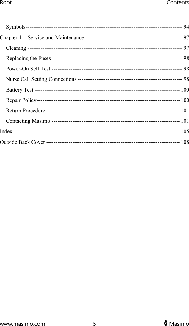


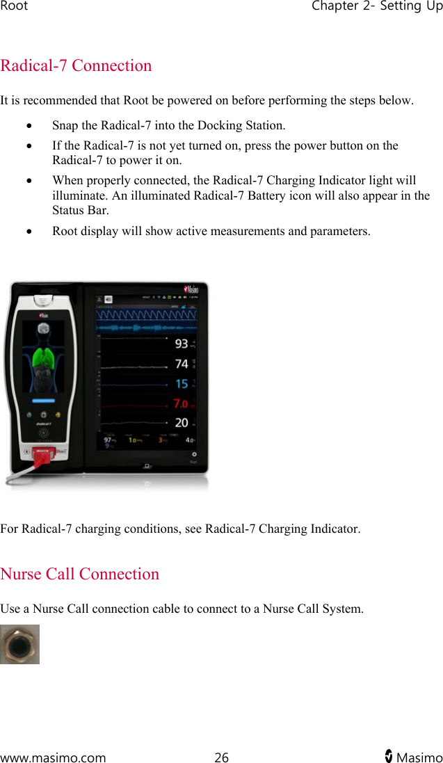
![www.masimo.com 23 Masimo Chapter 2- Setting Up Unpacking and Inspection To unpack and inspect Root 1. Remove Root from the shipping carton and examine it for signs of shipping damage or exposed electronics. 2. Check all materials against the packing list. Save all packing materials, invoice and bill of lading. These may be required to process a claim with the carrier. 3. Confirm that you have all components for the Root: Root AC Power Cord If anything is missing or damaged, contact Masimo's Technical Service Department. See Return Procedure. Guidelines for Setting Up Root has a built-in bracket interface that allows it to be mounted on a pole or roll stand. When setting up Root, follow these guidelines: Place on a stable, hard, flat and dry surface near the patient. Maintain a minimum of three (3) centimeters (one [1] inch) of free space around Root. Ensure that the back panel Speaker is not covered to avoid a muffled alarm sound. Charge Root's battery fully before use. See Initial Battery Charging. Root should not be operated outside the environmental conditions listed in the specifications section. See Environmental Specifications.](https://usermanual.wiki/Masimo/RDS7A/User-Guide-2552854-Page-25.png)


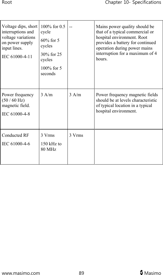
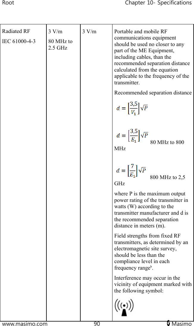
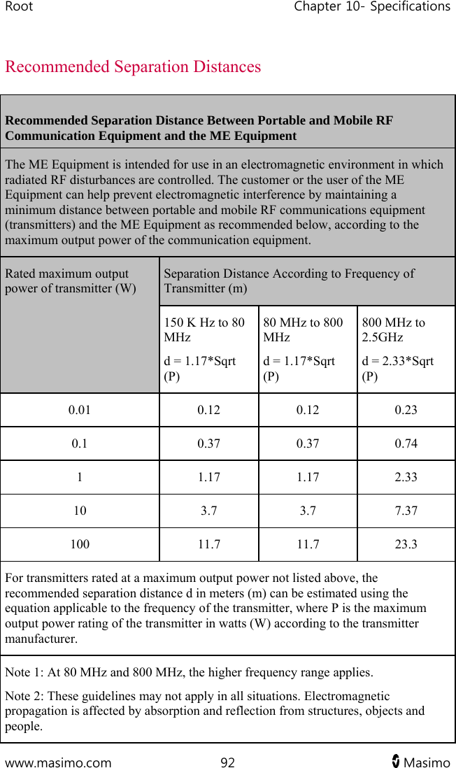
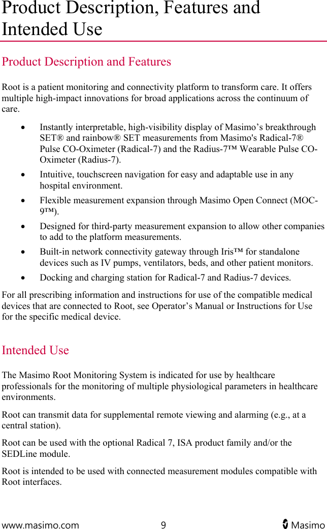
![Root Chapter 10- Specifications www.masimo.com 91 Masimo Note 1: At 80 MHz and 800 MHz, the higher frequency range applies. Note 2: These guidelines may not apply in all situations. Electromagnetic propagation is affected by absorption and reflection from structures, objects and people. Field strengths from fixed transmitters, such as base stations for radio (cellular/cordless) telephones and land mobile radios, amateur radio, AM and FM radio broadcast and TV broadcast cannot be predicted theoretically with accuracy. To assess the electromagnetic environment due to fixed RF transmitters, an electromagnetic site survey should be considered. If the measured field strength in the location in which the ME Equipment is used exceeds the applicable RF compliance level above, the ME Equipment should be observed to verify normal operation. If abnormal performance is observed, additional measures may be necessary, such as re-orienting or relocating the ME Equipment. b Over the frequency range 150 kHz to 80 MHz, field strengths should be less than [V1] V/m.](https://usermanual.wiki/Masimo/RDS7A/User-Guide-2552854-Page-93.png)