Master Bilt Bsd Series Users Manual NEW Basemount Install
BSD Series to the manual d327cb07-785c-4416-9c98-4c6d9780f036
2015-02-09
: Master-Bilt Master-Bilt-Bsd-Series-Users-Manual-553704 master-bilt-bsd-series-users-manual-553704 master-bilt pdf
Open the PDF directly: View PDF ![]() .
.
Page Count: 9
1 4/07
BSD SERIES
REFRIGERATORS AND FREEZERS
Installation, Operation and
Maintenance Instructions
INSPECTION
When the equipment is received, all items should be carefully checked against the bill of
lading to insure all crates and cartons have been received. All units should be inspected for
concealed damage by uncrating the units immediately. If any damage is found, it should be
reported to the carrier at once, and a claim should be filed with the carrier. This equipment
has been inspected and tested at the manufacturing facility and has been crated in
accordance with transportation rules and guidelines. Manufacturer is not responsible for
freight loss or damage.
INSTALLATION
GENERAL
If casters are installed, care should be taken when removing the unit from the crate base.
The unit is heavy and can present a hazard if not handled with care. Remove the unit crate
and crate base. Discard hardware used to secure the cabinet to the crate base. Ensure that
at least two persons are available to install the casters. Lay the cabinet on its back to
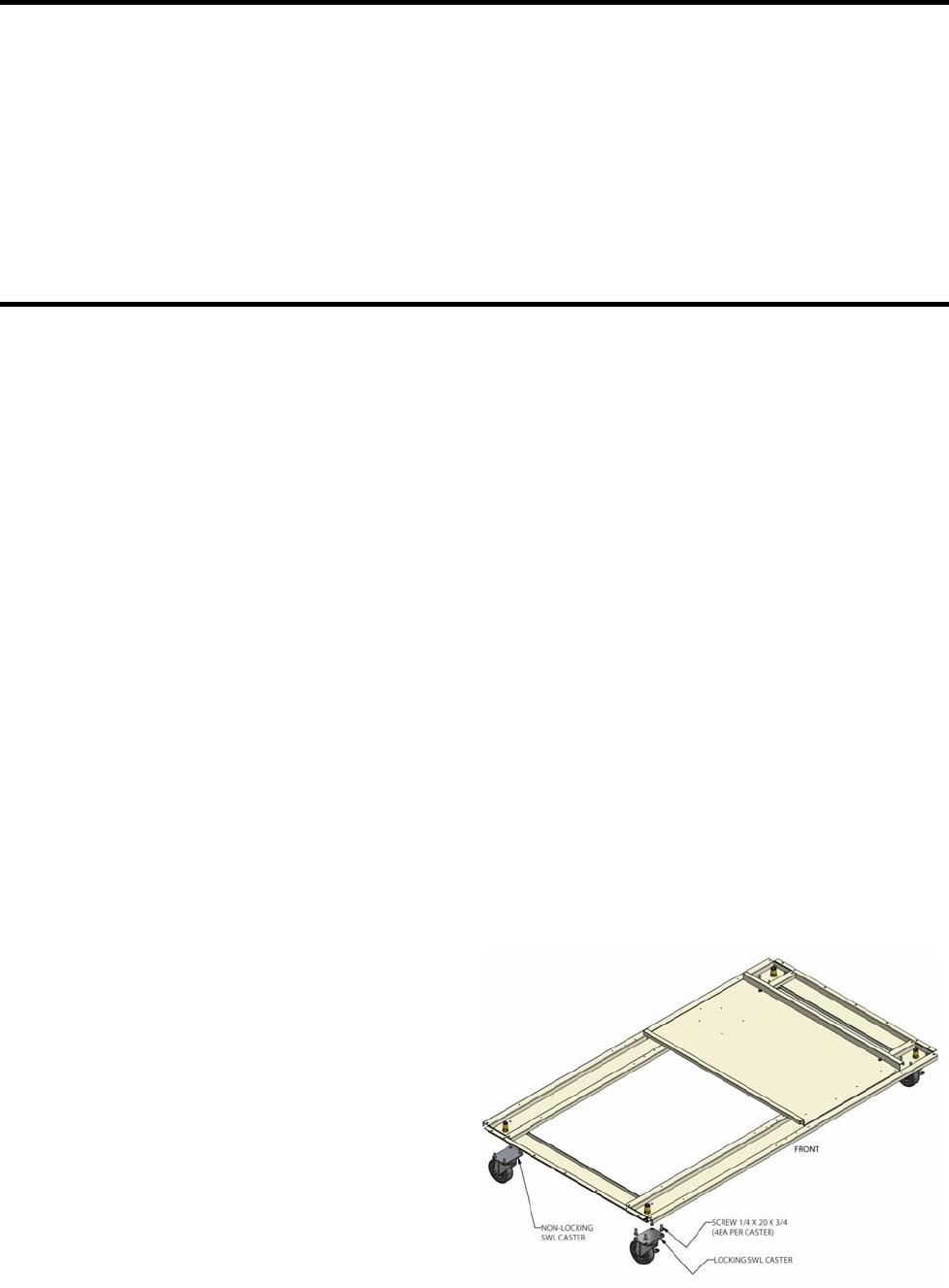
create access to the cabinet bottom. Attach the casters to the cabinet base suing the
factory installed screws as shown below.
Remove the ¼ x 20 x ¾ screws (4 per
caster) that are factory installed. Position the
caster and reinstall. Ensure that the locking
casters are installed on the front of the
cabinet. After installation is complete, return
the cabinet to its upright position. The
cabinet should set in the upright position for
at least one hour prior to energizing. This is
required to allow the refrigeration to settle to
its normal state. The cabinet should also be
levelled when it is placed in its permanent
location.
2 4/07
If the doors are out of alignment on the cabinet, the doors can be adjusted. This can be
accomplished by opening the door(s) and loosening the screws that hold both the top and
bottom hinges to the cabinet. After adjusting the door so that it is aligned correctly, tighten
the screws to securely hold the hinges in place.
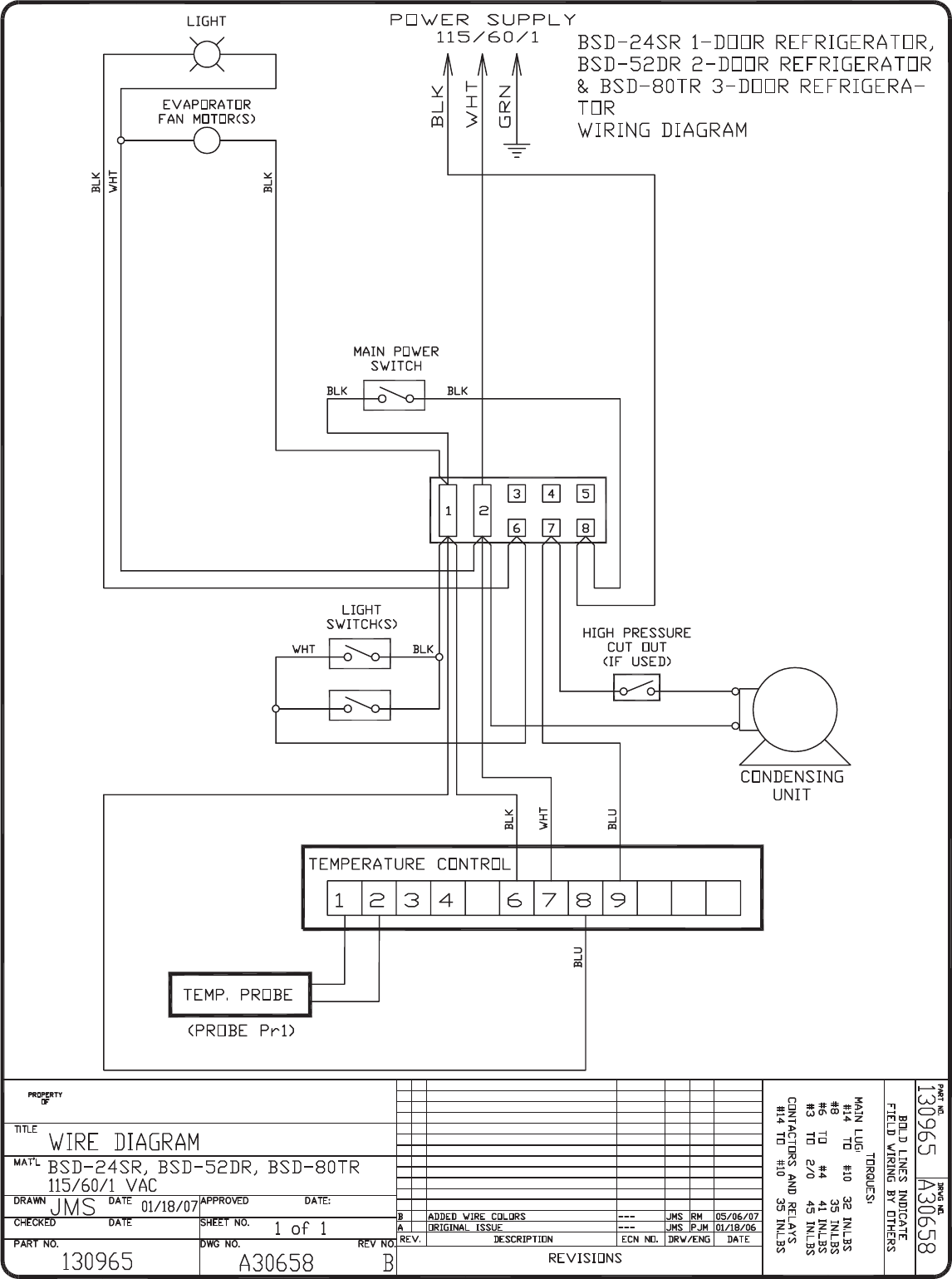
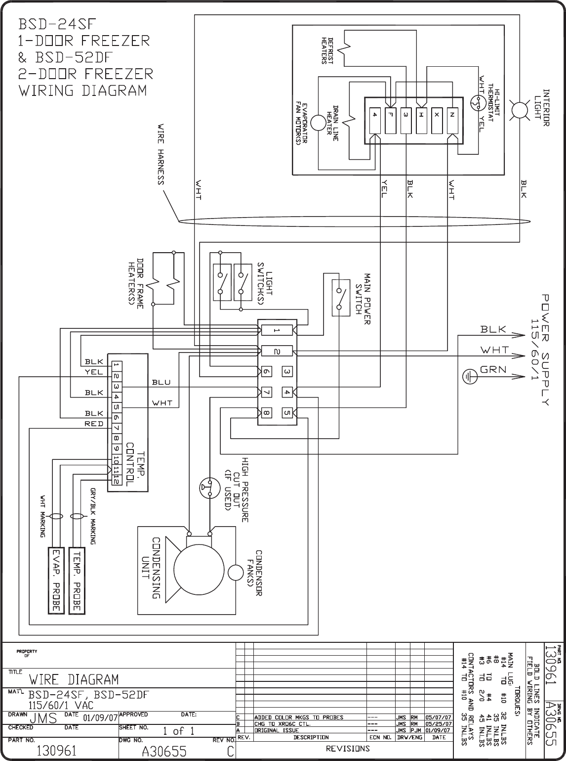
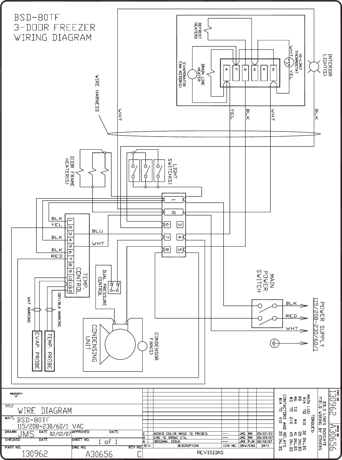
ELECTRICAL
Check the proposed outlet to be used to insure that the voltage, phase and current carrying
capacity of the circuit from the electrical panel correspond to the requirements of the
cabinet. NEVER use an extension cord to wire any unit. On permanently connected units,
those not furnished with a plug-in service cord, all inter-wiring between the electrical panel
and the unit must be done in accordance with the National Electric Code and all state and
local codes. Refer to the serial tag for all pertinent electrical information.
Observe all Warning Labels. Disconnect power supply to eliminate injury from
electrical shock or moving parts when servicing equipment.
GENERAL OPERATION
The refrigerators and freezers employ a unit cooler evaporator located outside the cabinet
as the heat removing source. Through the refrigeration process, heat is captured in the
evaporator, transferred to the condensing unit on top of the cabinet, and expelled to the
surrounding outside air. It is extremely important to allow a four (4) inch clearance on the
top, rear, and sides of the unit for the refrigeration process to function properly.
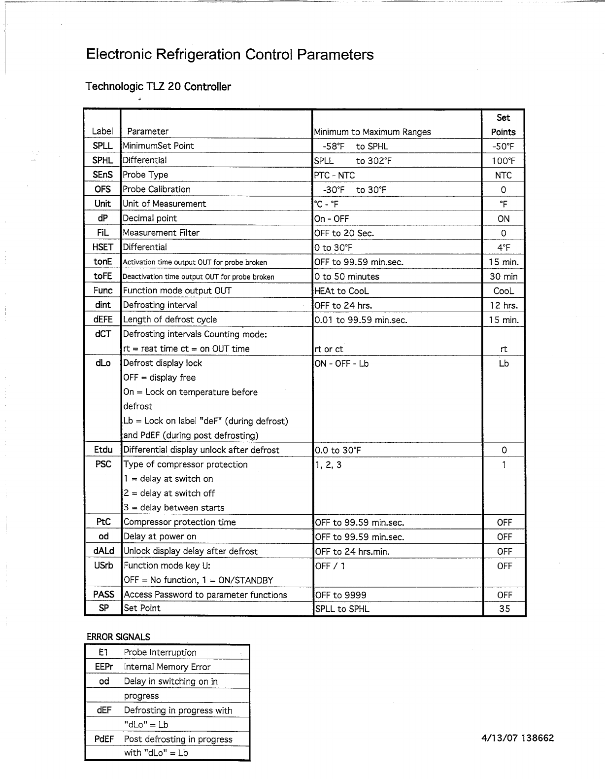
These refrigerators and freezers utilize a programmable controller to control the
temperature and defrost settings. The controller, which is located on the facade of
the unit, is factory set. Please see the default settings sheet and separate
instructions that are included on the operation of this controller.
REFRIGERATORS
During the operation of a refrigerator unit, frost will periodically form on the coil surface.
Each time the compressor cycles "off", the evaporator fans will continue to run, which will
keep the internal temperature uniform and at the same time remove any frost build up on
the coil. The water produced will collect in the unit cooler drain pan and travel down the
drain tube to the condensate vaporizer.
FREEZERS
After shutting the door on freezer models, a short amount of time must be allowed before
the door can be reopened. This is due to the tight seal maintained between the door and
the cabinet. Waiting a few moments for the pressure to equalize permits the door to be
opened easily.
A positive defrost is required to remove frost from the coil in freezer models. This is
accomplished by energizing heaters during the defrost cycle that are positioned on the coil
surface. The programmable controller is factory set to allow four defrosts per day.
3 4/07
As the preset defrost time is reached, the controller automatically terminates the
refrigeration process by turning off the condensing unit and unit cooler fan motors, and
energizes the defrost heaters. As the coil temperature increases, the frost begins to melt
producing water which runs down the coil to the unit cooler drain pan and exits through the
drain tube to the vaporizer. After all the frost has been removed and the coil temperature
reaches approximately 50°F [10ºC], the defrost is terminated through the action of the
defrost termination control located on the unit cooler, and the refrigeration process
resumes. In order to insure that any excess water remaining on the coil is not sprayed into
the cabinet interior, and all heat generated by the defrost is removed, the unit cooler fans
will not operate until the coil temperature reaches approximately 25°F [-4ºC].
GENERAL MAINTENANCE
PERIODIC CLEANING
Beginning with the initial installation, the interior surfaces of the cabinet should be
periodically wiped down with a solution of warm water and baking soda. This solution will
remove any odors from spillage that has occurred. The exterior of the cabinet should also
be cleaned frequently with a commercial grade of glass cleaner.
Monthly cleaning of the condenser will aid the heat transfer characteristics of the
refrigeration system and increase its efficiency. To accomplish this, remove the cover panel
from the cabinet and use a wire brush to loosen any dirt particles that are attached to the
fins. Use a vacuum cleaner to remove the loosened particles. Failure to keep the
condenser coil clean and clear of obstructions could result in temperature loss and
damage to the compressor.
All moving parts have been permanently lubricated and will generally require no
maintenance.

4 4/07
MAINTENANCE SERVICE AND ANALYSIS GUIDE
REFRIGERATION SYSTEMS - ALL MODELS
MALFUNCTION POSSIBLE CAUSE SOLUTION
Compressor will not start - 1. Service cord unplugged 1. Plug in service cord
no hum 2. Fuse blown or removed 2. Replace fuse
3. Overload tripped 3. Determine reasons and correct
4. Control stuck open 4. Repair or replace
5. Wiring incorrect 5. Check wiring against the diagram
Compressor will not start - 1. Improperly wired 1. Check wiring against the diagram
hums but trips on overload 2. Low voltage to unit 2. Determine reason and correct
protector 3. Starting capacitor defective 3. Determine reason and replace
4. Relay failing to close 4. Determine reason, correct or replace
Compressor starts and runs, 1. Low voltage to unit 1. Determine reason and correct
but short cycles on overload 2. Overload defective 2. Check current, replace overload protector
protector 3. Excessive head pressure 3. Check ventilation or restriction in
refrigeration system
4. Compressor hot-return gas hot 4. Check refrigerant charge, fix leak if necessary
Compressor operates long 1. Short of refrigerant 1. Fix leak, add charge
or continuously 2. Control contact stuck 2. Repair or replace
3. Evaporator coil iced 3. Determine cause, defrost manually
4. Restriction in refrigeration system 4. Determine location and remove restriction
5. Dirty condenser 5. Clean condenser
Compressor runs fine, but 1. Overload protector 1. Check wiring diagram
short cycles 2. Cold control 2. Differential too close - widen
3. Overcharge 3. Reduce charge
4. Air in system 4. Purge and recharge
5. Undercharge 5. Fix leak, add refrigerant
Starting capacitor open, 1. Relay contacts stuck 1. Clean contacts or replace relay
shorted or blown 2. Low voltage to unit 2. Determine reason and correct
3. Improper relay 3. Replace
Relay defective or burned out 1. Incorrect relay 1. Check and replace
2. Voltage too high or too low 2. Determine reason and correct
Refrigerated space too warm 1. Control setting too high 1. Reset control
2. Refrigerant overcharge 2. Purge refrigerant
3. Dirty condenser 3. Clean condenser
4. Evaporator coil iced 4. Determine reason and defrost
5. Not operating 5. Determine reason, replace if necessary
Standard temperature system 1. Control setting is too low 1. Reset the control
freezes the product 2. Control points stuck 2. Replace the control
Objectionable noise 1. Fan blade hitting fan shroud 1. Reform or cut away small section of shroud
2. Tubing rattle 2. Locate and reform
3. Vibrating fan blade 3. Replace fan blade
4. Condenser fan motor rattles 4. Check motor bracket mounting, tighten
5. General vibration 5. Compressor suspension bolts not loosened
on applicable models - loosen them
6. Worn fan motor bearings 6. Replace fan motor
Pan Area 1. No cooling 1. Make sure switch is in the "on" position
2. Too cold 2. Adjust temperature control - see instructions
under pan area
3. Too warm 3. Adjust temperature control - see instructions
under pan area

9/05 040625
INSTRUCTIONS FOR REVERSING
THE SWING OF SOLID DOORS
Complete the following steps if reversing the swing of the solid door(s) is desired. These steps apply to both
refrigerators and freezers.
1. With a one, two, or three door model, first open the door and locate the screws holding the hinges and door
in position.
2. Two people are recommended to make this change. One person should hold the door at a 90° angle to the
cabinet while the other person removes the screws holding the door to the cabinet. The normal installation
at the factory is to have the spring loaded door-closing mechanism located at the bottom of the cabinet.
When removing the spring tension bracket from the cabinet bottom, be careful that it does not snap
back. This may result in pinched fingers.
3. After the door(s) are removed, remove the door lock strike(s) from the cabinet by removing the two mounting
screws.
4. Find the holes, drilled through the outer skin only, located on the opposite side of the door opening from
where the hinges were previously located. Drill through the tapping plate found behind these holes using a
7/32" drill bit.
5. Turn the door over and align it to the cabinet so it will swing in the desired direction. The spring loaded door-
closing hinge will now be located at the top of the reversed door. Mount the hinges to the cabinet using the
holes that were drilled out in step 4, along with the previously removed screws. Check the door(s) to be
certain that it is mounted squarely and that the gaskets seal properly around the door opening. The door can
be adjusted by moving the top or bottom hinge slightly.
6. The original hinge holes can be filled with silicone, or with 1/4-20x3/4 pan head stainless steel screws if
desired.
7. Locate the door lock strike by visually aligning it to the dead bolt lock in the door while the door is in the
closed position. While holding the strike in position, mark the top, bottom, and edge of the strike on the
cabinet wall or mullion with a pencil or fine point marker that will remain legible until completion of the task.
Verify that the strike is positioned properly by assuring that it is aligned to the marks and hold it securely;
open and close the door and extend and retract the dead bolt to make certain they clear without touching.
The strike cannot be adjusted after it is mounted.
8. Align the strike to the marks, which were made in step 7 and mark the centers of the holes for the mounting
screws. Using a #20 drill bit, drill the holes you just marked approximately one-half inch deep. Take care
not to puncture the interior side of the cabinet. Note: If a #20 bit is not available, use a 5/32" drill bit.
9. Mount the door lock strike using the screws that were removed from the original position. The screws may
have to be forced until the thread cutting tip has passed through the entire metal thickness. The original door
strike holes can be filled with silicone, or with two 10-24x1/2 stainless steel pan head screws if desired.