Master Lock 27213 27213 Electronic Access Control User Manual Exhibit D Users Manual per 2 1033 b3
Master Lock Company 27213 Electronic Access Control Exhibit D Users Manual per 2 1033 b3
Exhibit D Users Manual per 2 1033 b3
Master Lock Company LLC, Milwaukee, WI 53154 U.S.A. | 800-574-7260
©2017 Master Lock Company LLC | All Rights Reserved. 1 P57672 REV A
27213 Keypad and 27211 Weather Cover Kit Guide
Rev A
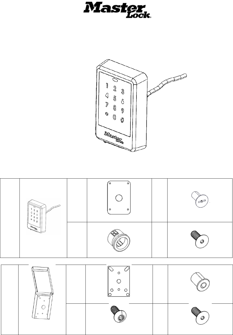
27213 Package Contents
Qty 1
27213 Master Lock
Bluetooth Keypad
Qty 1
Keypad Gasket
Qty 4
#10-32 x ½ Flat Head Screws
Qty 2
Grommets
Qty 4
#10-32 x ½ Hex Screw SS
Qty 1
27211 Weather Cover
(Optional Accessory)
Qty 1
27211 Weather Cover Gasket
Qty 4
#10-24 Nutserts
Qty 4
#10-24 X ½ Long Button Head
Screws
Qty 4
10-32 x ½ Flat Head Screws
Master Lock Company LLC, Milwaukee, WI 53154 U.S.A. | 800-574-7260
©2017 Master Lock Company LLC | All Rights Reserved. 2 P57672 REV A
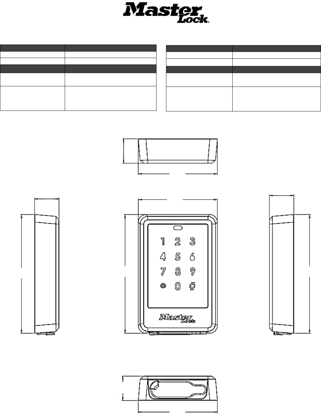
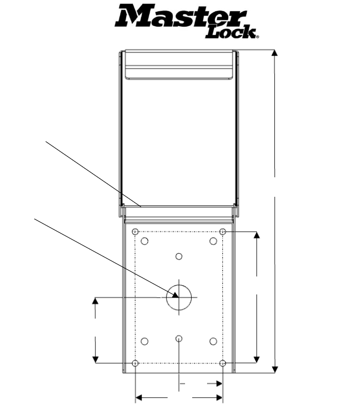
Keypad Dimensions (Inches)
Specifications
Mechanical
Shipping Weight
2 lbs
Dimensions
3 1/2” W x 4 7/8”H x 1”D
Electrical
Power Consumption
60 mA @ 3 VDC typical
350 mA peak
Cable Requirements
4 twisted pair-wire, 22 AWG Min.,
50ft max
Environmental
Operating Temperature
-40oF to 158oF
Humidity
Up to 95% RH
Regulatory
FCC Class:
47 CFR, Part 15, Sub Part C
NEBS
Tested to select subsections of
GR-487
1.00
4.87
1.00
3.25
3.25
4.87
1.00
4.87
1.00
3.25
Master Lock Company LLC, Milwaukee, WI 53154 U.S.A. | 800-574-7260
©2017 Master Lock Company LLC | All Rights Reserved. 3 P57672 REV A
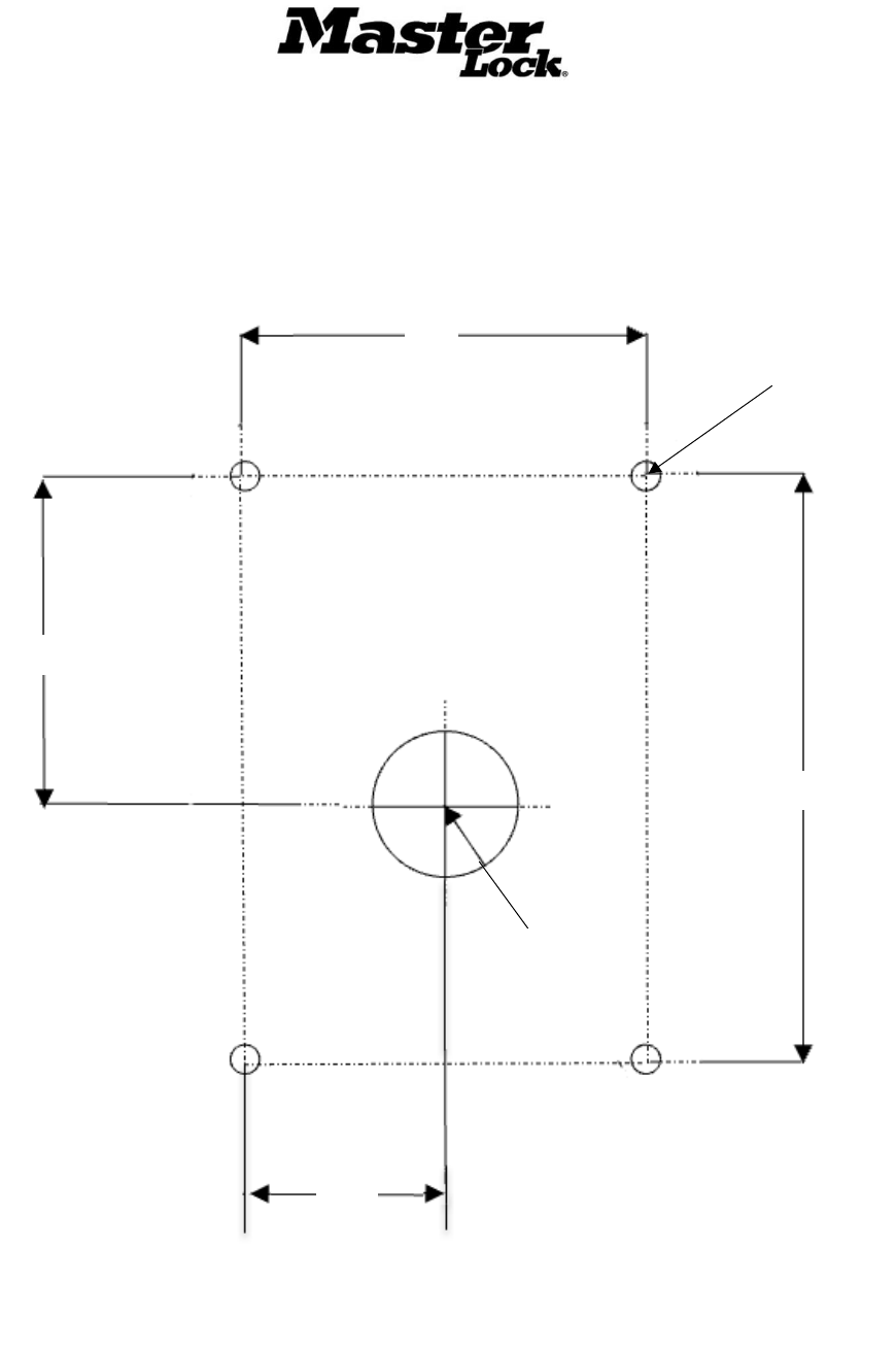
Keypad Mounting Hole Pattern Dimensions (Inches)
.297” ø 19/64”
4 Places
5/8” ø
4.00
2.25
2.75
1.375
Master Lock Company LLC, Milwaukee, WI 53154 U.S.A. | 800-574-7260
©2017 Master Lock Company LLC | All Rights Reserved. 4 P57672 REV A
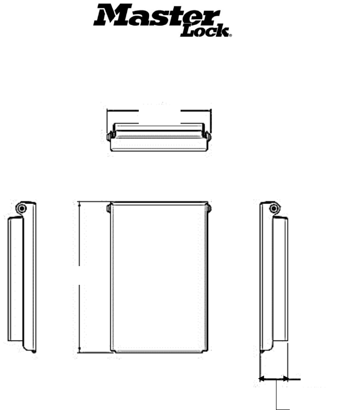
Weather Cover Dimensions (Inches)
5.11
7.44
Master Lock Company LLC, Milwaukee, WI 53154 U.S.A. | 800-574-7260
©2017 Master Lock Company LLC | All Rights Reserved. 5 P57672 REV A
Tools & Materials
Safety Glasses
7/32” (.218”) Drill Bit
Hearing Protection
19/64” (.297”) Drill Bit
Gloves or Similar Hand Protection
Cordless Drill (1/2”)
Tape Measure (1/16” graduations)
Step Drill Bit
Pencil
Nutsert Install Tool and Bits
ESD Approved Vacuum
#10-24 Tap
Automatic Center Punch
#10 Flat head Screw Driver
#10 Hex Driver
The Tools list and provided hardware is suitable for use with installations on metal surfaces. Different tools and hardware
(not provided) may be required for proper installation on other mounting surfaces.To ensure proper mounting, use hardware
type and sizes that are suitable for your specific installation.
Product Notice:
This product is not intended or rated for use in life-critical control applications. Please verify requirements for your specific
installation by consulting electrical code and other local regulations and obtain approvals in writing.
FCC: This equipment has been tested and found to comply with the limits for a Class A digital device, pursuant to part 15
of the FCC Rules. These limits are designed to provide reasonable protection against harmful interference when the
equipment is operated in a commercial environment. This equipment generates, uses, and can radiate radio frequency
energy and, if not installed and used in accordance with the instruction manual, may cause harmful interference to radio
1.86
14.88
7/32” (.218) ø
4 Places
5.25
2.625
3.50
1.75
1.00 ø
Master Lock Company LLC, Milwaukee, WI 53154 U.S.A. | 800-574-7260
©2017 Master Lock Company LLC | All Rights Reserved. 6 P57672 REV A
communications. Operation of this equipment in a residential area is likely to cause harmful interference in which case the
user will be required to correct the interference at his own expense.
Warning: Any modification without the express written consent of The Master Lock Company LLC could void
your authority to operate this product and invalidate the product warranty.
Model 27213 Bluetooth Keypad
The 27213 Bluetooth Keypad is an access control keypad reader that is part of the Master Lock Bluetooth family of products. The
Keypad works with the 27219 and 27220 Door Controllers to provide entry at shelters, cabinets and others equipped with Master Lock’s
high-security electromechanical locks. Devices are managed within the Master Lock Vault Enterprise Access Control System (ACS)
and use credentials issued by (ACS,) including Temporary Access Codes (TACs) for manually entered or mobile credentials from the
Master Lock Vault Enterprise Bluetooth mobile app.
These elements of the system function together to provide convenient and simple access control and management without requiring a
real-time network connection with the ACS Host.
General Capabilities
Access is granted through use of the Master Lock Vault Enterprise App (App) installed on a Bluetooth 4.0 capable-device or a manually
entered Temporary Access Code (TAC) at the Keypad. When the Keypad communicates a valid credential to the Door Controller, the
controller sends power to unlock the locks. The Door Controller stores transaction data, which is also uploaded to ACS by the App
through the Keypad’s Bluetooth connection.
The Keypad is also used to deliver firmware and configuration updates to the Door Controller. The Keypad provides information about
errors and battery status via its LED indicator. The Keypad LED status is mirrored on an indicator on the Door Controller board.
The Keypad offers a battery jump port that provides a connection for a 9V battery to supply power to the Door Controller if all other
power sources have become unavailable.
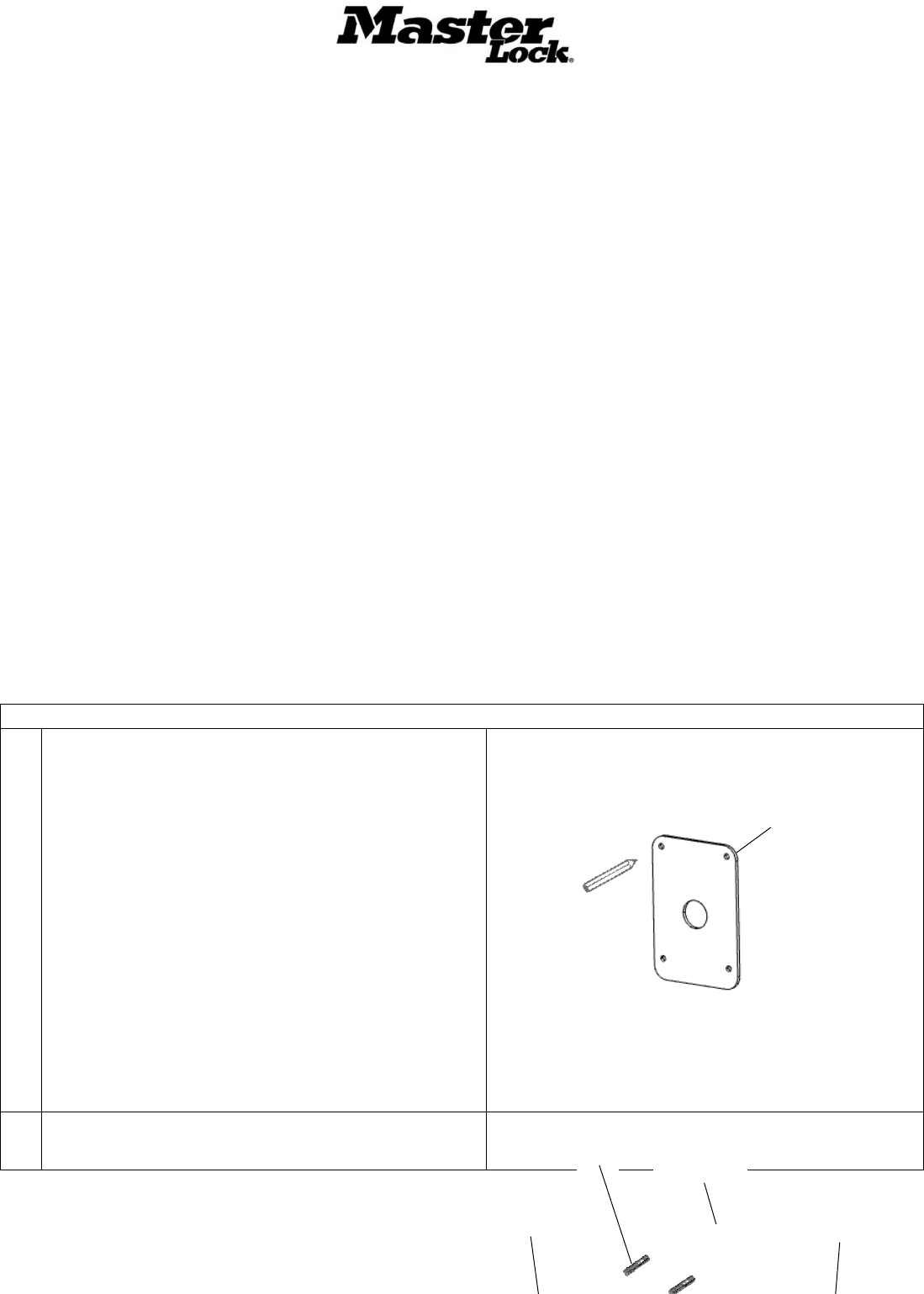
Preparation and Installation
Keypad Installation (Direct Mounting)
1.
Measure
1. Identify the desired vertical height for your installation.
(Note: Ensure compliance with regulations and guidelines
for accessibility)
2. Refer to the keypad mounting dimensions on pg 3 to mark
the mounting holes and keypad cable through-hole on the
mounting surface. Center punch all marks.
3. Using the center mark, create a 5/8” opening for the
keypad cable through-hole using a drill and step bit.
4. Drill (4) 7/32” (.218”) holes in the punched locations
completely through the door to the other side.
NOTE 1: Grommets of 5/8” diameter are provided to
protect the cable from sharp edges. Insert a grommet in
both sides of the cable through-hole if desired.
NOTE 2: Access to both the front and back of the
mounting surface is necessary for this mounting method.
2.
Install (4) #10-32 studs of appropriate length into the mounting
holes on the back of the Keypad (not provided)
Keypad Gasket
Bluetooth Keypad
Studs
Keypad Gasket
Master Lock Company LLC, Milwaukee, WI 53154 U.S.A. | 800-574-7260
©2017 Master Lock Company LLC | All Rights Reserved. 7 P57672 REV A
3.
Feed the keypad cable through the center hole in the mounting
surface
4.
Align the Keypad with the mounting surface so that the studs
pass through the (4) mounting holes.
5.
Thread the washers and lock nuts (not provided) onto the studs
and tighten.
6.
Trim the studs if necessary
Skip to Connecting the Keypad Steps on Page 6
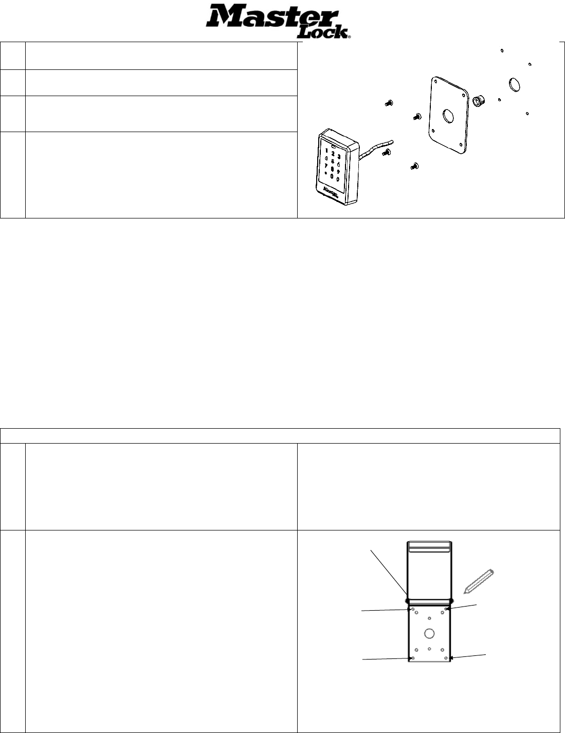
Installing the Keypad with a Weather Cover
1.
Prepare Mount
Identify the desired vertical height for your installation. (Note:
Ensure compliance with regulations and guidelines for
accessibility)
NOTE: Grommets of 5/8” diameter are provided in the weather
cover kit to protect the cable from sharp edges.
2.
Mark
1. Position the Weather Cover on the front of the mounting
surface, centered and leveled over the 5/8” hole.
2. Mark the (4) mounting holes at the outer edge of the back
plate. Set aside the cover.
3. Drill (4) holes of a size suitable for the mounting hardware
appropriate for your wall condition.
Follow steps 2.4 and 2.5 if you are using nutserts
otherwise proceed to step 3.
4. Center punch and drill (4) 19/64” (.297”) holes in the
punched locations.
5. Install the (4) nutserts into the holes using a nutsert install
tool.
Mounting Holes
Weather Cover
Mounting Holes
Mounting Holes
Mounting Holes
Master Lock Company LLC, Milwaukee, WI 53154 U.S.A. | 800-574-7260
©2017 Master Lock Company LLC | All Rights Reserved. 8 P57672 REV A
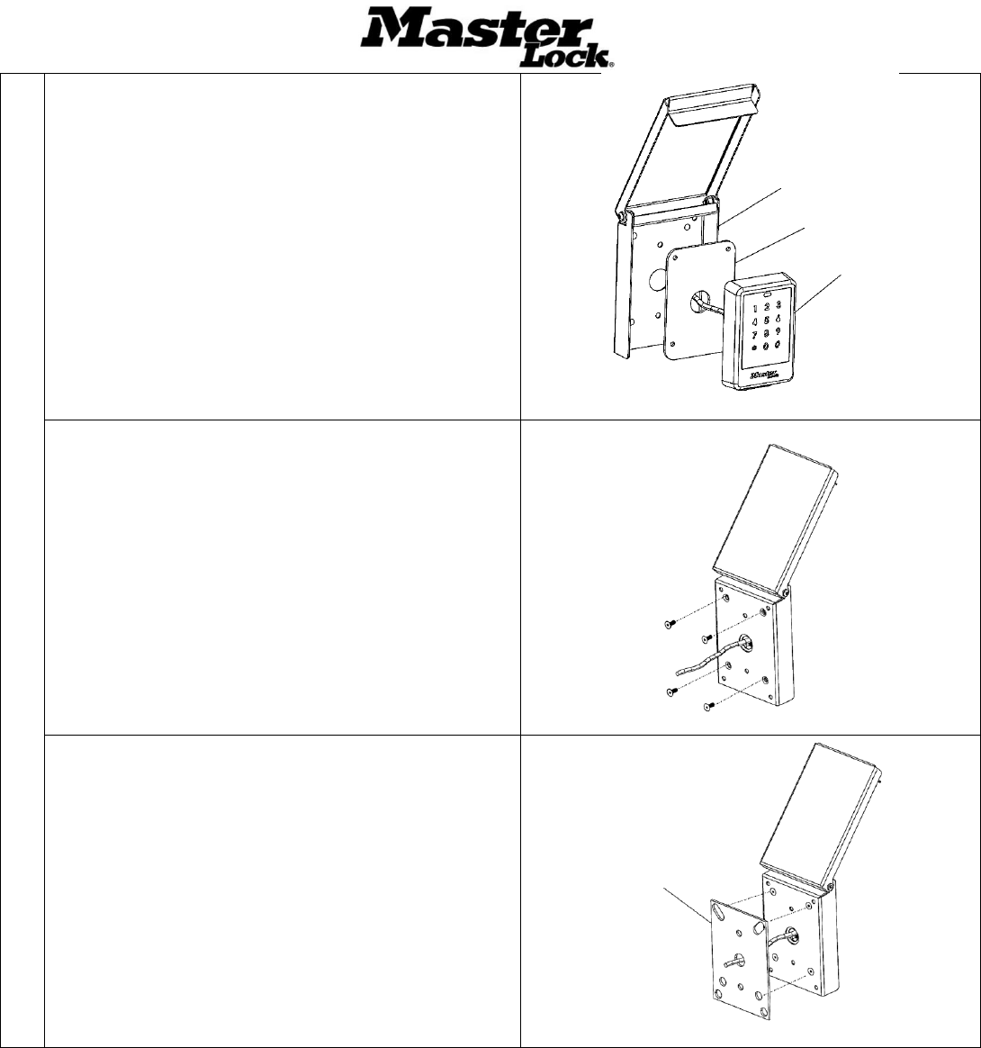
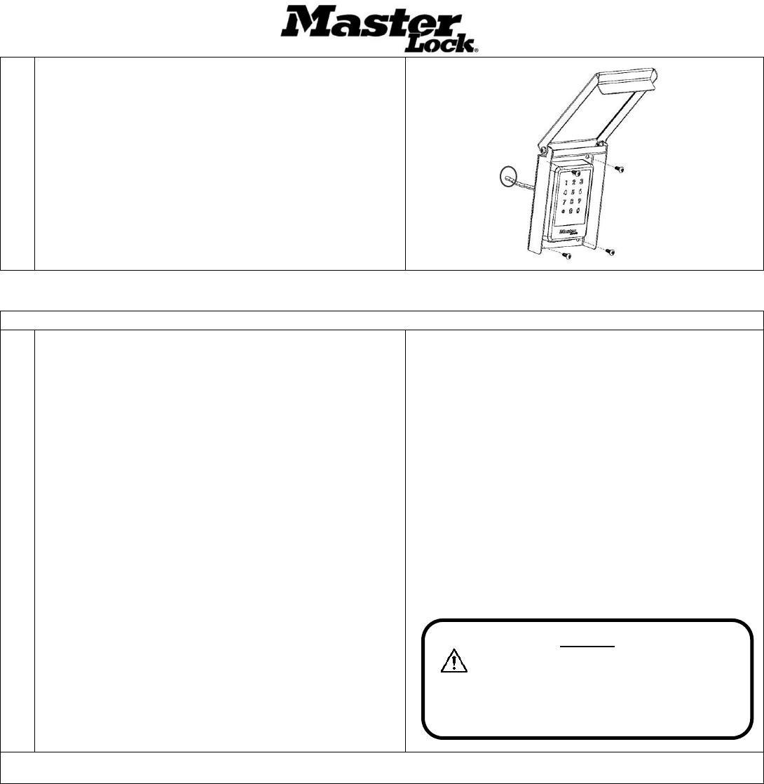
3.
Assemble
1. Place the Keypad Gasket followed by the Bluetooth
Keypad 27213 into the Weather Cover, aligning the center
hole and mounting holes. Pass the keypad wire pigtail
through the center holes.
2. To attach the Keypad to the weather cover, insert the (4)
#10-32 x ½ flathead screws into the mounting holes in the
Weather Cover exterior as shown.
3. Place the Weather Cover Gasket over the back of the
Weather Cover with the wires from the Keypad passing
through the center of the Keypad Cover Gasket.
Weather Cover
Keypad Gasket
Bluetooth Keypad
Weather Cover Gasket
Master Lock Company LLC, Milwaukee, WI 53154 U.S.A. | 800-574-7260
©2017 Master Lock Company LLC | All Rights Reserved. 9 P57672 REV A
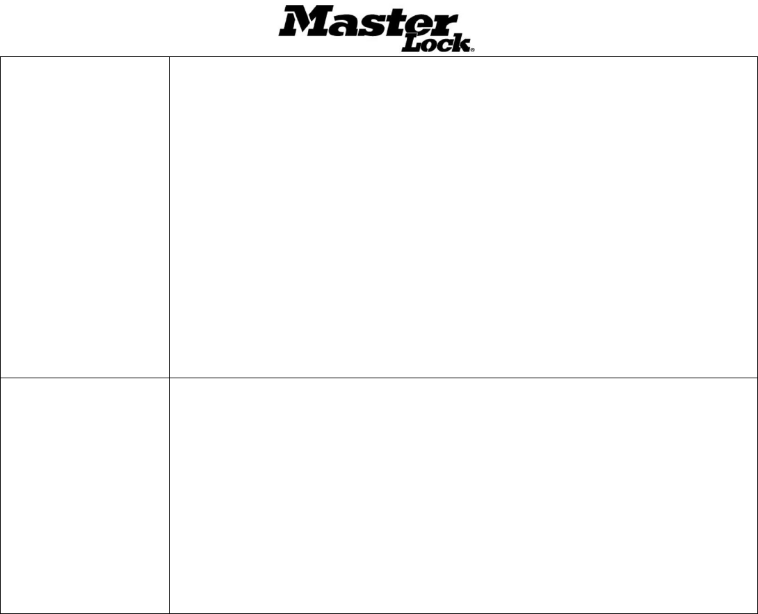
4.
Install
1. Pass the Keypad wires through the center hole in the
prepared mounting surface.
2. Attach the assembled Bluetooth Keypad 27213 and
Weather Cover 27211 using (4) #10-24 x 1/2” Long
Button Head Screws.
Activating the Keypad
5.
Connect
Follow the keypad wiring chart to connect the Keypad cable to
the keypad terminal connector provided with the Door
Controller.
1. Loosen the terminal screws on the connector
2. Insert stripped and prepared wire ends. Make sure the
wire pairs remain together in their correct sequence.
3. Tighten the terminal screws, ensuring the wires are firmly
engaged
NOTE: The Keypad cable can be extended using 22AWG
twisted pair wire to a maximum total length of 50 feet using a
splicing method appropriate for your installation.
For more information about making connections, review the
Door Controller Installation and User Manual
Keypad Wiring Chart
Wire Color
Terminal Position
Signal Name
Black
BK
Ground GND
White/Black White
WE
V+ 3VDC
Red
RD
Battery Jump
White/Red White
WE
Tamper input
Brown
BN
TX +
White/Brown White
WE
TX-
Orange
OE
RX+
White/Orange White
WE
RX-
Configuration
Warning!
Ensure Power Source and Door Controller
Battery Board Switch are OFF before connecting or
disconnecting devices to the Controller. Failure to
observe this precaution may cause damage.
Master Lock Company LLC, Milwaukee, WI 53154 U.S.A. | 800-574-7260
©2017 Master Lock Company LLC | All Rights Reserved. 10 P57672 REV A
6.
Configure
Note: For the Keypad to function, the Door Controller must be
powered and setup in ACS. Consult the Door Controller
Installation and User Manual for instructions.
1. With the Master Lock Vault Enterprise App open on your
mobile device, wake the Keypad by touching the face of
the keypad. The Keypad will light and the LED will
illuminate blue.
2. The Controller name will appear as a selectable option in
the app. Select the controller
3. Use the App to unlock the door. This will pass the config
to the controller
7.
Test
Verify the Keypad operation by testing credentials
1. Wake the Keypad by touch the keypad surface and
present a valid credential using the App or entering a
TAC on the keypad.
2. Verify that the Keypad responds as expected according
to the chart on Page 9.
Installation is now complete.
For more information about system configuration or use, please
consult the ACS Software User Manual and Door Controller
Installation and User Manual, or consult your System
Administrator.

Master Lock Company LLC, Milwaukee, WI 53154 U.S.A. | 800-574-7260
©2017 Master Lock Company LLC | All Rights Reserved. 11 P57672 REV A
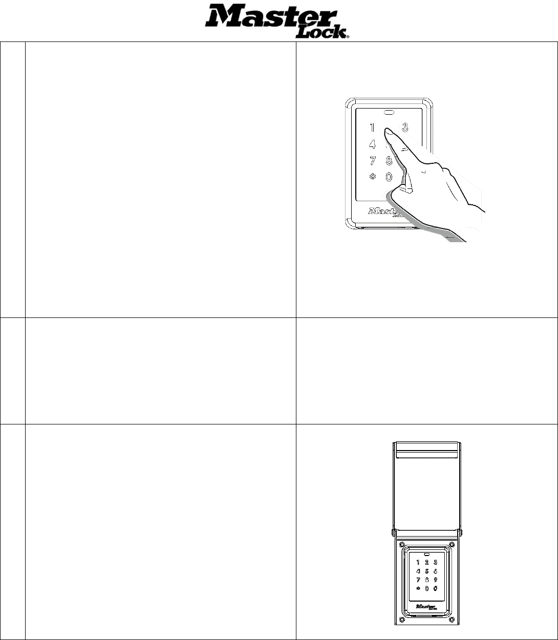
Use
Wake the Keypad
Touch any area of the keypad number plate until backlight and LED
Illuminates.
Note: The Mobile App will not detect the Keypad unless it is awake
Enter a TAC
• Wake the Keypad.
• Enter *1
• Enter the TAC number and press #
Access using the Master
Lock Vault Enterprise
Mobile App
• Open the App
• Wake the Keypad
• Select the corresponding device in the App and follow the App prompts
Use the Battery Jump
• Remove the black rubber plug from the bottom of the Keypad
• Use a small screw driver to retrieve the battery jump connector pad from the keypad
base. Tug gently to extend. Remove the plastic cover on the battery connector (Do not
discard.
• Connect a 9V battery to the leads and wait 1 minute for the Keypad to charge
• Wake the Keypad
• Enter a valid credential using a TAC or the Mobile App
NOTE 1: Door locks require a pulse to relock. The 9V battery must remain connected
until either the power is restored, Door Controller batteries are replaced or the relock time
has expired.
• After removing the 9V battery replace the plastic cover on the battery connector
• Place the connector back into the bottom cavity on the keypad.
• Replace the black rubber plug
NOTE 2: Failure to do these steps will leave the unit suceptable to electrical and
environmental damage
Update Firmware
1. With the Master Lock Vault Enterprise App open on your mobile device, wake the Keypad by
touching the face of the keypad. The Keypad will light and the LED will illuminate blue.
2. The Controller name will appear as a selectable option in the app. Select the controller
3. Once selected, the app will ask if it can begin the firmware update. Select “Yes”
4. The app will notify you when the update is complete. Do not move during the update.
Keypad Status Indicators
State or Condition
LED State
Audio Response
Sleep
Off
Off
Key Press*
Backlight blink
Short tone
Low Battery
Yellow, fade 8 seconds
Master Lock Company LLC, Milwaukee, WI 53154 U.S.A. | 800-574-7260
©2017 Master Lock Company LLC | All Rights Reserved. 12 P57672 REV A
Contact Information
Technical Support: 800-574-7260 or acsupport@mlock.com
Website: www.masterlock.com
Main Power
Blue, solid
Battery Power
Blue, slow blinks
Entry Error
Red, solid
Entry Timeout
Red, fade
Denied
Red, solid
Rapid tones
Success
Green, rapid blink
Long tone
Penalty Delay
Red, solid
Rapid tones
Audit Trail Upload
Blue, fast blink with pause for duration
Firmware Download
Blue, fast blink with pause for duration
*Blink function depends on mode. See Backlight Behavior for details
Backlight Performance
A DayNight setting is available
in ACS to manage backlight
behavior.
Mode
Function
Backlight Response**
All
Sleep
Off
Low light
Wake
Keypress
On,
Blinks Off
DayNight Enabled (default)
Wake
Keypress
Off
Blinks On
DayNight Disabled
Wake
Keypress
On
Blinks Off
**To conserve battery life, the backlight will not illuminate if Door Controller voltage is below 2.4V