Master Lock 4843DATSEN Back up/Towing Camera User Manual ok
Master Lock Company Back up/Towing Camera ok
Users Manual
Master Lock Towing Camera Installation and Operation Instructions:
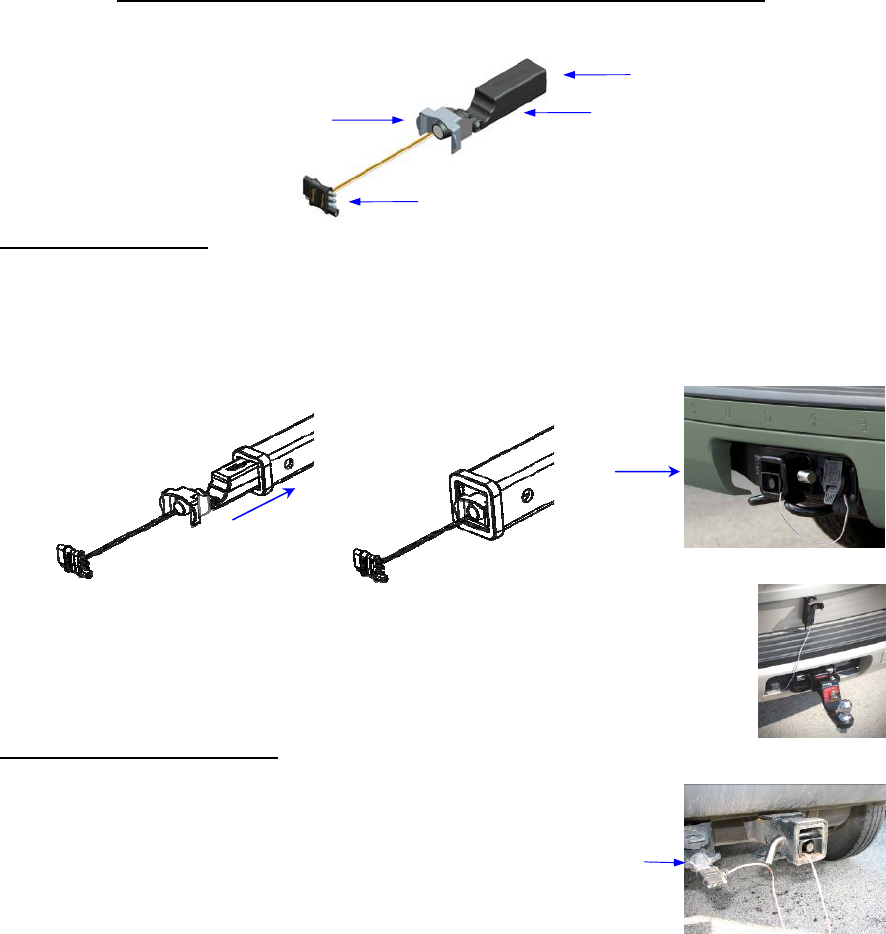
Camera Features
Camera Installation:
The camera has two mounting options/applications:
1) Back-up Camera- Slide the camera assembly inside a 1-¼” or 2” hitch receiver tube. The
magnet in the camera base will hold it securely in place. The plastic guide on the camera
bracket will help line the assembly up with the hitch pin opening and allow a standard or
locking hitch pin to be used for additional security.
2) Hitch Alignment/Load Monitoring System- Mount the camera to any
metal surface on the back of the vehicle using the magnetic base. The soft
pads on the base will prevent sliding or scratching and the camera bracket
can pivot up to 90° to allow the field of view to be adjusted.
Camera Power Connection:
The camera is powered by plugging the camera power
connector into the vehicle’s towing wiring harness. The
camera power connector is a 4 position connector that
directly attaches to many vehicles. The camera power
connector also has a pass-though design feature. This
allows you to plug your trailer wiring into the open end
of the backup camera power connector and monitor your
trailer load while towing. Some vehicles may need a 7
position to 4 position adapter, which is not included.
Note: A readily available 4 position tow wire extension (not included) will allow the camera
to be mounted further away from the vehicle plug for gooseneck or fifth wheel trailer hitch
alignment applications.
Notice: Depending on the make/model of the vehicle, the running lights or headlights may
need to be turned on to power the vehicle’s tow plug.
1-1/4” Tube 2” Tube
Pin Guide
Antenna
Transmitter Housing
Camera Power Connector
7 position to
4 position
adapter shown
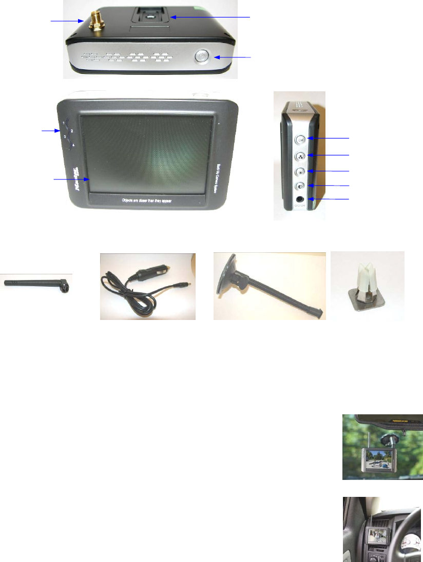
Monitor Features
NOTE: OBJECTS ARE CLOSER THAN THEY APPEAR ON THE MONITOR
Monitor Hardware Included:
Antenna:
The wireless antenna attaches to the threaded connector on the back of the monitor. Once
attached, it can be rotated 360° for optimial picture clarity.
Mounting:
When choosing a location to mount the monitor, make sure the monitor is
in an area that will not obstruct your vision while driving or interfere with
access to any of the vehicle controls. It can be placed on the windshield
using the flexible mounting arm or clipped to an air vent. Both options use
the mounting slot on the back of the monitor.
1) Temporarily place the monitor stand or clip in the location that you
have chosen and route the power cable to the vehicle’s 12V power
outlet verifying the cable does not interfere with the safe operation of
the vehicle or access to any vehicle controls.
2) To use the mounting arm, remove the vinyl protector from the suction
cup base and place it firmly on a smooth surface. Rotate the small cam
near the base of the arm to hold in place. Slide the arm into the
mounting slot on back of monitor.
Vent Cli
p
Wireless Antenna
Power and
Channel LED
Indicator
Power button (On/Off)
Wireless Channel
Brightness
Contrast
No function
DC Input
Mounting Slot
Threaded Wireless
Antenna Connector
Flexible Mounting Arm w/
Suction Cup Base
Power Cable
Mounting Arm
Vent Clip
3.5” LCD TFT
Display, 480x234

3) To use the vent clip, slide clip into the monitor mounting slot and gently press the clip and
monitor over the vehicle air vent fins.
Power Connection:
1) Insert the small DC plug of the power cable into the DC12V opening on the side of the
monitor.
2) Insert the larger 12 Volt power plug into the vehicle auxiliary power socket. The red LED
on the power plug will come on if the vehicle socket has power.
Notice: Depending on the make/model of the vehicle the ignition may need to be turned on
or to the accessory position for the 12V socket to have power.
Monitor Controls:
Power Button - Press the Power button to turn the display ON, the blue LED will appear,
indicating the monitor is ON. Press it again to turn the display OFF, the blue LED will
turn off.
Wireless Channel – This monitor can accept 4 different channels of wireless transmission.
To change the channel, press the “CH” button and it will go to the next channel, at
channel 4 it will return to channel 1. The camera is pre-set to channel 4.
Blue LED Power and Wireless Channel Indicator - When the monitor is ON the blue
LED will be lit. The location of the blue LED on the left side of the monitor also
indicates what channel the display is set to.
Brightness - There are 6 levels of brightness. To adjust the brightness, press the Brightness
Control button. Press the button to increase the brightness, at the highest level it will
return to the lowest level.
Contrast Control - There are 6 levels of contrast. To adjust the contrast, press the Contrast
Control button. Press the button to increase the contrast, at the highest level it will return
to the lowest level.
Notice: Under extreme bright light conditions, the screen image may take a few seconds to
automatically adjust. It is best to wait until the image has stabilized before backing up.
Testing the System:
1) Turn the vehicle ignition to the accessory position. Do not start the vehicle.
2) Turn on the monitor - the blue LED should come on.
3) IF there is no picture on the display:
a. Confirm that monitor is set to channel 4
b. Turn vehicle lights on
4) Adjust the monitor antenna for the best picture.
Notice: Re-locating the monitor even a small amount inside the vehicle can affect the
picture quality. This device, as well as all other wireless devices, may be subject to
interference caused by cell phones, Bluetooth headsets, Wi-Fi routers, power lines and
other various electrical equipment, etc. including other cameras.

Warning:
This device complies with part 15 of the FCC Rules. Operation is subject to the following two
conditions:
(1) This device may not cause harmful interference, and
(2) This device must accept any interference received, including interference that may cause
undesired operation.
Changes or modifications not expressly approved by the party responsible for compliance could
void the user's authority to operate the equipment.