Matrix Interactive LP2500A Remote User Manual
Matrix Interactive LLC Remote
user manual
i
Table o f Co n T e n T s
1. OVERVIEW AND FEATURES ....................................................................................1
2. LIMITATION OF LIABILITY ........................................................................................5
3. CONSOLE CONTROLS AND INDICATORS .........................................................7
Console Top View ................................................................................................... 7
Console Bottom View ...........................................................................................9
Console Rear View ................................................................................................. 9
Console Right Side View ...................................................................................10
4. PENDANT CONTROLS AND INDICATORS .......................................................11
Pendant Front View .............................................................................................11
5. GETTING STARTED: BASIC SETUP .....................................................................13
Step 1: Connect your Prodigy Console .....................................................13
Step 2: Insert the Pendant Battery ..............................................................16
Step 3: Enter Setup Mode ...............................................................................16
Step 4: Register the Pendant to the Console .........................................17
Step 5: Program Your Emergency Phone Numbers ............................18
Step 6: Record Your Outgoing Message (Optional) ............................19
6. OPTIONAL FEATURES SETUP ...............................................................................23
The Primary Contact ...........................................................................................23
Test Required Interval ........................................................................................23
Setting the System Clock .................................................................................23
Automatic Test Call Setup ................................................................................24
Notification Setup ................................................................................................25
Console Low Battery Notification Setup .............................................25
Failed Pendant Notification Setup .........................................................26
Social Safety Setup ........................................................................................27
Cancel Button Confirmation Sound: Chime or Barking Dog ..........28
Override the Default 911 Emergency Number ......................................29
7. OPERATING YOUR LIFELINK PRODIGY .............................................................31
ii
Emergency Operation ........................................................................................31
Triggering an Emergency: What to Expect ........................................31
Direct to 911: Triggering an Emergency Call Directly to 911 ...32
What if the Emergency Call is not Answered? .................................32
Cancelling the Emergency Call Process ..............................................32
Two-Way Communication .........................................................................32
Disconnecting the Emergency Call .......................................................33
The Notification Process ...................................................................................33
Console Low Battery Notification Process .........................................33
Failed Pendant Notification Process......................................................34
Social Safety Process ....................................................................................35
Checking System Status ....................................................................................35
Visual Status Indicators ...............................................................................35
Audible Status Messages ...........................................................................36
Checking System Status through a Directly-Attached Phone . . 37
Checking System Status Remotely ........................................................37
Testing Your System ............................................................................................38
Testing Strategy ..............................................................................................38
A Note About the TEST REQUIRED Indicator LED ...........................38
Running a Test Manually.............................................................................39
Running a Test Automatically ..................................................................39
Things to Know About the Test Call Process (Manual and Auto-
matic) ...................................................................................................................40
8. MISCELLANEOUS FUNCTIONS ..........................................................................41
Power On ..................................................................................................................41
Power Off ................................................................................................................41
Reset/Reboot..........................................................................................................41
Using a Telephone That is Connected to Your Prodigy ......................41
Line Seize Functionality ....................................................................................42
Reset to Factory Defaults ..................................................................................42
9. PRODIGY OPERATION DURING A POWER OUTAGE...................................43
iii
LED Indicator Lights During a Power Outage .........................................43
Audible Voice Message Warning During a Power Outage ................43
For Extended Power Outages .........................................................................43
After a Significant Power Outage .................................................................44
10. MAINTENANCE OF YOUR SYSTEM ..................................................................45
Changing Batteries ..............................................................................................45
Changing the Console Battery ................................................................45
Changing the Pendant Battery ................................................................45
Pendant Use in the Shower or Bath Tub....................................................46
Cleaning ...................................................................................................................46
11. TROUBLESHOOTING AND TECHNICAL SUPPORT ....................................47
What if I Can’t Get Prodigy to Work? ...........................................................47
Your Phone Service is Tied Up after Phone System Outage ............48
Prodigy with DSL Service ................................................................................48
Prodigy Doesn’t Recognize the “0” Key .......................................................49
Prodigy Won’t Roll Over to the Next Number .........................................49
For Detailed Troubleshooting Information ..............................................49
12. THE FCC WANTS YOU TO KNOW .....................................................................51
FCC Notice ...............................................................................................................51
Radio Frequency Interference Statement.................................................51
Canadian Doc Notice..........................................................................................51
Ringer Equivalent Number ..............................................................................52
APPENDIX A: GLOSSARY OF TERMS .....................................................................53
APPENDIX B: FACTORY DEFAULT SETTINGS .....................................................55
APPENDIX C: DESIGN GOALS .................................................................................57
Primary Design Goals: Form and Function ...............................................57
Primary Design Goals: Intelligence and Awareness ............................58
APPENDIX D: SETUP MENU QUICK REFERENCE .............................................61
APPENDIX E: SAFETY ..................................................................................................65
APPENDIX F: DISCLAIMERS AND LIMITED WARRANTY ...............................67
APPENDIX G: TECHNICAL SPECIFICATIONS ......................................................69
iv
THIS PAGE INTENTIONALLY LEFT BLANK
v
© 2012 Matrix Interactive LLC. All rights reserved.
LifeLink Prodigy®, the LifeLink logo, and graphics are registered trademarks or
trademarks of Matrix Interactive LLC Inc. All other trademarks are the property
of their respective owners.
Reproduction, adaptation or translation without prior written permission is
prohibited, except as allowed under the copyright laws. Information in this User
Guide is subject to change without notice and does not represent any commit-
ment on the part of Matrix Interactive LLC. No part of this User Guide may be re-
produced or transmitted in any form or by any means, electronic or mechanical,
including photocopying, recording, or information storage and retrieval systems,
or translated to another language, for any purpose other than the licensee’s
personal use and, as specically allowed in the licensing agreement, without the
express written consent of Matrix Interactive LLC.
Release 1.25-001
CT.TS005.003904
vi
Please read this manual completely and save it for future reference.
Thank you for choosing LifeLink® Prodigy personal emergency alert system.
Prodigy is your reliable link to the outside world if you’ve fallen and cannot get
to a telephone to call for help. Prodigy is packed with well-thought-out features,
not the least of which include no activation cost, no contracts, and no monthly
fees. Specically:
We oer “simplicity out of the box” with “Simply. Smarter.” technology. •
Only two steps are required to make your Prodigy fully operational -- 1)
register at least one Pendant, and 2) program at least one emergency
phone number. Simply follow the section titled “Getting Started: Basic
Setup” , or follow the Quick Start Guide, and your system will be ready to
use in less than 15 minutes.
Up to eight (8) emergency phone numbers can be programmed to call, •
even 911.
Up to twelve (12) Pendants can be registered with the Console.•
Two-way communication capability enhances the ability to exchange •
critical information during an emergency.
Prodigy has enhanced range from Pendant to Console oering up to a •
500-foot range in open air.
A “Direct-to-911” function can be initiated by the user if they feel that •
their emergency may be life-threatening and warrants 911 attention.
Using the Direct-to-911 feature, the system bypasses all programmed
emergency numbers and contacts 911 directly.
Prodigy has a number of intelligent operational checks and balances •
making it the most reliable system available on the market today.
Prodigy was engineered in the United States, ensuring that only the •
highest of quality innovation, techniques, standards, approaches, and
testing is incorporated into your system.
For a full list of signicant features and benets, refer to the section titled Over-
view and Features. For a review of our design goals and engineering method-
ology, refer to Appendix C: Design Goals.
Note that, within this Guide, the terms LifeLink, Prodigy, and LifeLink Prodigy
are used interchangeably. Each is a registered trademark or trademark of Matrix
Interactive LLC.
1. OVERVIEW AND FEATURES
1
1. oVeRVIeW anD feaTURes
Your new LifeLink Prodigy, referred to within this Guide simply as “Prodigy”, is
American-engineered with industry knowledge spanning more than ten years.
Our engineers, in conjunction with some of the best customer service personnel
in the world, have worked together to develop the most eective emergency
alert system available on the market today. We’ve leveraged thousands of hours
of feedback directly from you, our customers, regarding missing, ineective and/
or unnecessary features of legacy and competitor systems. This feedback has
been incorporated into the engineering and design of our state-of-the-art sys-
tem. We are proud to introduce Prodigy, the “simply smarter” emergency alert
system.
Before continuing with this Guide, it is recommended that you
review the glossary of terms in Appendix A.
Your Prodigy system’s features include the following:
Key Features of your Table 1. Prodigy System
Ca T e g o R y fe a T U R e DesCRIpTIon
SETUP
Voice-Based Configuration
and Status
To facilitate ease of use, all configuration and
detailed status checking is done through voice
prompts, similar to setting up a voicemail
system.
Optional Remote Setup
While setup can be done locally, if desired,
the entire system can be set up from a remote
phone. You can also check the status of the
system remotely.
Ease of Setup and Use
Our slogan is “Simplicity out of the Box”.
This means that getting your system
operational is quick and easy through the
“Basic Setup” menu option. Additionally,
the design team deliberately didn’t include
computer networking technology, USB,
cellular, Bluetooth, and other computer-based
technologies. Being in the technology field
for many years, we have come to realize that
technology should match your customer
base, and an overabundance of computer
technology, often for its own sake, can add
unnecessary complexity yet yield little value.
For example, some technologies such as GPS,
cellular, etc. require a daily battery charge; in
our experience, this is a lot to require of our
typical customer.

2
1. OVERVIEW AND FEATURES
Ca T e g o R y fe a T U R e DesCRIpTIon
CONSOLE
Phone Service
Interoperability
Prodigy is designed to work with traditional or
digital/Voice Over IP (VoIP) phone services.
Adjustable Siren/Speaker
The volume level of the siren/speaker is
adjustable. Additionally, you can disable the
siren altogether. Siren volume sound range,
if programmed to sound, is from 30 to 80
decibels.
Reduced External
Components Increasing
Durability
Engineers have deliberately reduced the
number of visible external components to
significantly increase durability. The absence
of an external keypad, LCD screen, and antenna
are some examples. These components tend
to break easily.
Dual CANCEL and HELP
Buttons
HELP and CANCEL buttons exist on the
Pendant as well as the Console. This facilitates
triggering or cancelling the emergency process
from either.
Two-Way Communications A built in VOX unit facilitates two-way voice
communications on the Console.
Line Seize Technology
The Console can interrupt an off-hook/busy
telephone and seize the phone line to enable
an outbound emergency call. Note that this is
only possible for a locally-attached phone or
phone system such as that with “base+satellite”
DECT cordless phone systems.
Call Progress Feedback
The user can hear the progress of an
emergency call (as well as test and notification
calls) through the speaker on the Console.
Internal Flash Memory
Some competing systems lose their
configuration if they lose both primary and
backup power. With Prodigy, all configuration
is saved on internal flash memory.
Expanded Number of Dialed
Digits with Pause Capability
The system can dial up to 20 digits.
Additionally, pressing the * key when
programming your phone number creates a
1-second pause when the number is dialed.
Power On (Ease) and Off
(Difficulty)
The system is engineered to be easy to power
on (press and hold POWER ON/OFF for 1
second) and requires intent to power off (press
and hold POWER ON/OFF for 5 seconds). This
prevents an accidental power off.
Backup Battery
Compartment
In an effort to increase the durability of the
system, instead of the damage-prone 9-volt
battery “clips”, engineers have designed the use
of the more durable “contacts”.

1. OVERVIEW AND FEATURES
3
Ca T e g o R y fe a T U R e DesCRIpTIon
PENDANT
Large HELP Button
In response to complaints that the HELP button
wasn’t large enough on competitor and legacy
systems, the Prodigy pendant has a larger HELP
button that will be easier to find and press. It
also has a raised “ray” design for ease of use.
Long Range
916MhZ FSK (frequency shift keying) wireless
technology allows for a range from Pendant to
Console of up to 500 feet in open air.
Pendant Water Resistance Pendant is designed to be used in the shower
or bath tub.
Pendant Supervision
Pendants automatically “check in” with the
Console to report their status. Missed status
reports or status reports noting a low Pendant
battery invoke various notification mechanisms
including a flashing LED on the Console, or
optionally, making an outbound notification
telephone call to the Primary Contact.
Screwless Pendant Battery
Replacement
Screwless Pendant access allows for ease of
changing the battery within the Pendant
without the need to use small tools and screws
which can damage the system, can be lost, are
difficult to use for the elderly, etc.
Optional Wrist Pendant
While the base system comes with a neck
Pendant, a wrist Pendant can be purchased
separately.
STATUS
Status LEDs
Various LEDs illuminate green if all is well or
flash red if there is a problem. For example, if
a problem with the phone line is detected, the
LINE STATUS LED will begin flashing red.
Status Voice Messages
Various status voice messages play over the
speaker if there is a critical problem that must
be addressed. These include such messages
as the system running on backup battery, that
there is a problem with the phone line, etc.
Status Notification Calls
Prodigy can be optionally configured to make
an outbound telephone call if it is determined
that there is a problem with a Pendant or if the
backup battery in the Console is low on power.

4
1. OVERVIEW AND FEATURES
Ca T e g o R y fe a T U R e DesCRIpTIon
TESTING
Automatic System Tests
The system can be configured to automatically
run a system test on a schedule you define.
During the test, an outbound test call (or calls)
is made. To minimize anxiety on the part of
the call recipient, test calls play a test message
rather than the emergency message.
Manual End-to-End System
Tests
The manual test button (“RUN A TEST” button)
allows you to run an end-to-end system test
whenever you want. The manual test simulates
very closely the actual emergency process,
though a test message is played rather than
the emergency message.
Test Reminder
The “Test Required” LED flashes red if a
successful test hasn’t been run in 30 days
or more (by default). The number of days is
configurable from 1 to 30.
911
911 Compliancy
Prodigy is fully 911-compliant in all 50
states. If 911 is dialed, by default, two-way
communication is immediately opened, and
the pre-recorded message is never played. For
countries outside of the USA that utilize an
emergency number other than 911, the system
allows you to program what is known as the
“911 Equivalent Number”.
“Direct to 911” function
Pressing the blue HELP button on the
Pendant three times within a 5-second period
instructs the system to automatically skip all
programmed phone numbers and dial 911 (or
equivalent) immediately. 911 does NOT need
to be in your call sequence to use this feature.
OTHER
Social Safety Alarm
The system can be programmed to require a
physical press of the CANCEL button (on the
Pendant or the Console) once each day at
the specified time in response to an alarm-
clock-like sound. If the physical press is not
sensed by the system, the system begins the
emergency calling process.
Barking Dog
When the CANCEL button is pressed, by
default, a chime is heard on the Console.
The system can optionally be set to sound a
barking dog. In an effort to ensure a natural-
sounding bark, the system cycles through
different bark patterns for each press of the
CANCEL button.
FCC and UL Certification System is UL-listed and FCC certified.

2. LIMITATION OF LIABILITY
5
2. lIMITaTIon of lIabIlITy
This section contains a summary of the Disclaimers and Limited Warranty
disclosed in full at the end of this Guide. It is important that you read them.
The purchaser agrees, by using this product, to the terms and conditions noted
below and in the Disclaimers and Limited Warranty. The purchaser also agrees
to read and follow all instructions and warnings on the product as well as those
documented within this Guide.
It is the sole responsibility of the purchaser and any user to assure that your
Prodigy is installed and programmed properly and that the unit is used and
maintained correctly. This includes, but is not limited to, periodic use and/or
testing to ensure that your Prodigy, including batteries, is in proper working
order, that the unit is located in an appropriate location in the home, that the
electrical outlet is supplying power, and that the user has been educated as
to the operation and functionality of the product as a whole. Your Prodigy
equipment is not designed or guaranteed to prevent any loss or injury.
The Disclaimers and Limited Warranty set forth in full at the end of this
Guide constitutes the terms of sale and use of the Prodigy equipment (and
accessories), and if, notwithstanding these terms of sale and use of the product,
there should arise any liability on the part of Matrix Interactive, LLC as a result
of any cause whatsoever, regardless of whether or not such loss, damage, or
personal injury was caused by or contributed to by Matrix Interactive, LLC’s
negligence to any degree or failure to perform any obligation or strict product
liability, such liability will be limited to an amount paid by the Purchaser for the
product. Further, Matrix Interactive, LLC has no obligation to assure that calls
are made, received, or responded to, nor is Matrix Interactive, LLC responsible for
acts, or consequences of the acts, of those responding. Matrix Interactive, LLC
provides no monitoring service for this product. It is up to the persons at the
numbers called to respond in an appropriate manner.

6
2. LIMITATION OF LIABILITY
THIS PAGE INTENTIONALLY LEFT BLANK
3. CONSOLE CONTROLS AND INDICATORS
7
3. Console ConTRols anD InDICaToRs
Your Prodigy system is made up of two main components: the system Console,
or “Console,” and the neck Pendant, or “Pendant.” Refer to the following sections/
diagrams for the location of various controls and indicators of your Prodigy
system. These controls are referenced throughout this Guide.
In general, all solid green indicator lights (LEDs) indicate that the system is
operating well. Red and/or blinking LEDs are cause for concern and indicate
that the system is in need of attention.
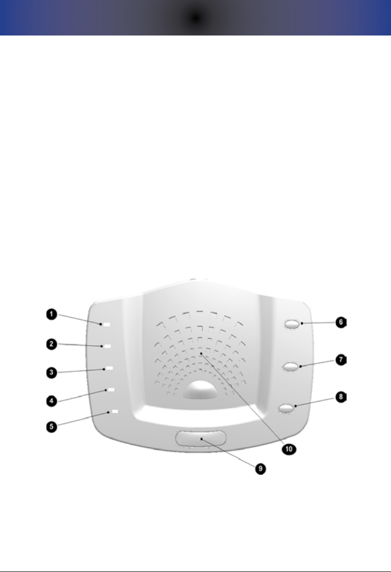
Console Top View
The top view of your Prodigy Console is the most important view, particularly
once your system is put into operation. You will note that the top/face of the
system is angled or tilted slightly to help ensure that the indicator LEDs are
easily seen from any point within a room. The gure below shows the controls
and indicators on the top of the Console.
Console Top ViewFigure 1.
See the table below for a description of each of the indicators shown above.
8
3. CONSOLE CONTROLS AND INDICATORS
Console Top Controls and IndicatorsTable 1.
Re f # IT e M sT a T U s /fUnCTIon
1AC POWER
Indicator Light
Solid Green = AC power OK.
Blinking Green = AC power out; system running
on backup battery.
2CONSOLE BATTERY
Indicator Light
Solid Green = Console battery power OK.
Blinking Red = Console battery power is low and
replacement is needed.
3PENDANT STATUS
Indicator Light
Solid Green = All Pendants are operating properly.
Blinking Red = At least one Pendant has reported a problem
(Pendant is not reporting or the Pendant battery is low).
4LINE STATUS
Indicator Light
Solid Green = Phone line is OK.
Blinking Red = There is a problem with the phone
line/connection, or the phone line is in use.
5TEST REQUIRED
Indicator Light
Solid Green = A system test is not needed at this time.
Blinking Red = A system test is recommended at this time.
6SETUP Button Press the SETUP button once to initiate Local Setup Mode.
Press the SETUP button twice to initiate Remote Setup Mode.
7CANCEL Button
Press the CANCEL button to cancel any current function
(for example, the emergency calling process). This button
functions identically as the small gray CANCEL button on the
Pendant.
8RUN A TEST Button Press the RUN A TEST button to initiate a system test (referred
to as the “Manual System Test”.
9HELP Button
Press the blue HELP button to initiate the emergency calling
process. This button functions identically as the blue HELP
button on the Pendant.
10 Speaker This ray-like area houses the internal speaker.
3. CONSOLE CONTROLS AND INDICATORS
9
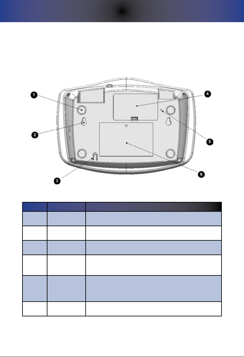
Console Bottom View
The bottom of your Prodigy Console provides access to various system
components -- the backup battery compartment, eyelets that allow you to wall
mount the system, a reset button, and other features as noted below.
Console Bottom ViewFigure 2.
Console Bottom ControlsTable 2.
Re f # IT e M fUnCTIon
1Foot Pads Rubber foot pads facilitate slide-free (padded) tabletop
installation. Table-top placement is typical.
2Wall Mount
Eyelets Eyelets allow you to wall mount the system if desired.
3MIC This is the microphone for the system that allows for two-way
communications.
4
Console
Backup Battery
Compartment
This compartment stores the 9-volt backup battery that the
Console uses in the event of an AC power outage.
5RESET button
This button allows you to reset the system in the event that it
appears to be “frozen”. This is similar to the reboot function of
a computer. This buttons does NOT reset the system to factory
defaults, though the system clock is reset to 12:00am.
6Informational
Sticker General information sticker.
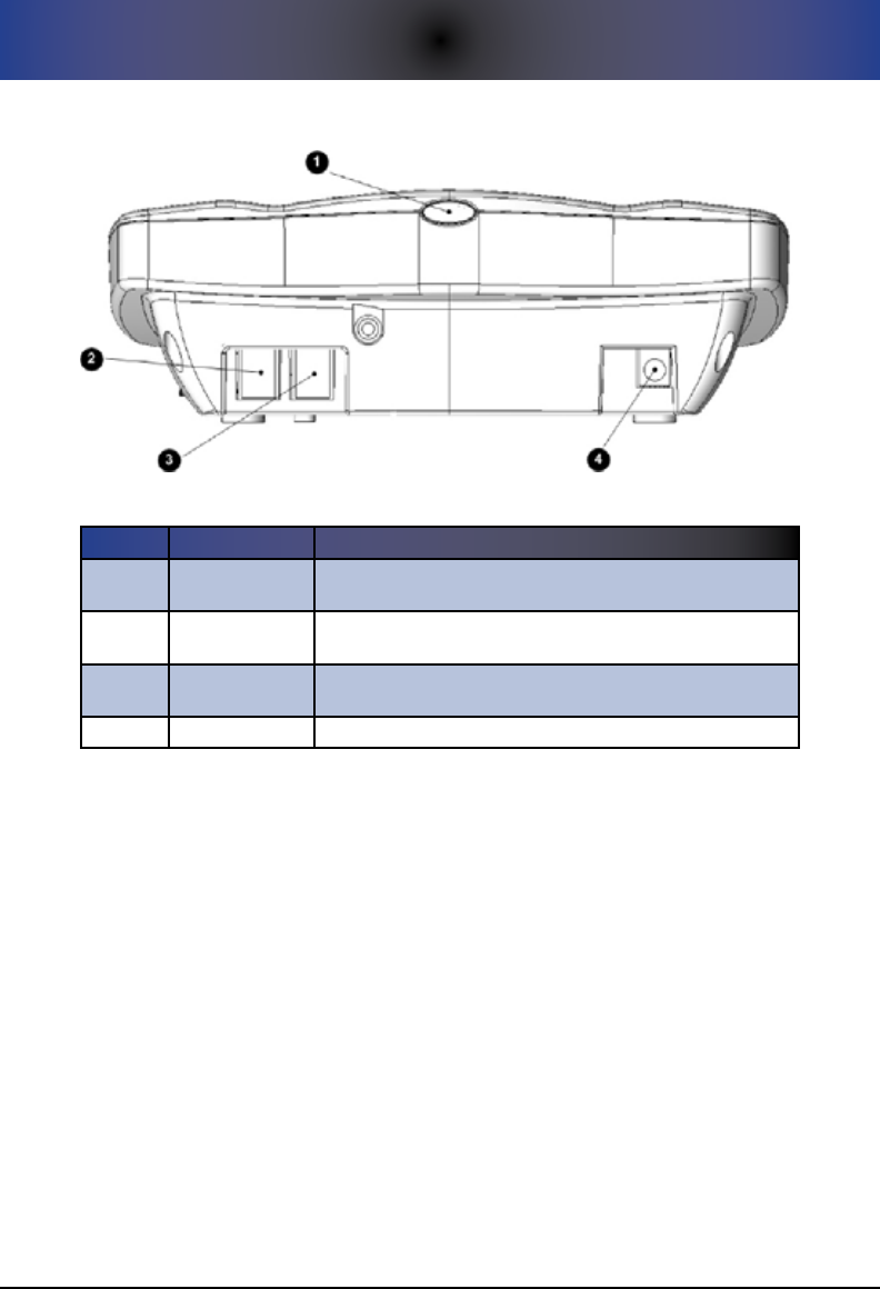
Console Rear View
The rear of your Prodigy Console contains the power button as well as all of
the ports for connecting your Console to a phone jack, a phone (optional), AC
power, and optional external equipment.
10
3. CONSOLE CONTROLS AND INDICATORS
Console Rear ViewFigure 3.
Console Rear DescriptionsTable 3.
Re f # IT e M fUnCTIon
1POWER ON/OFF
Button This is the button used to power the Console on or off.
2TO PHONE This is the RJ11 jack to connect your home phone to your
Prodigy Console.
3TO WALL This is the RJ11 jack to connect your Prodigy Console to a
telephone wall jack.
4POWER IN Supports the AC power supply to power the Console.
Console Right Side View
Located on the right hand side of the Console is the volume control knob/wheel
which allows you to control the volume level of the speaker inside your Prodigy.
The eective volume range is between 30 decibels and 80 decibels. You should
be careful not to force the knob past the extreme low and extreme high volume
levels to avoid breaking the knob and/or housing. Note that the decibel scale is
a logarithmic scale and not a linear scale.
4. PENDANT CONTROLS AND INDICATORS
11
4. penDanT ConTRols anD InDICaToRs
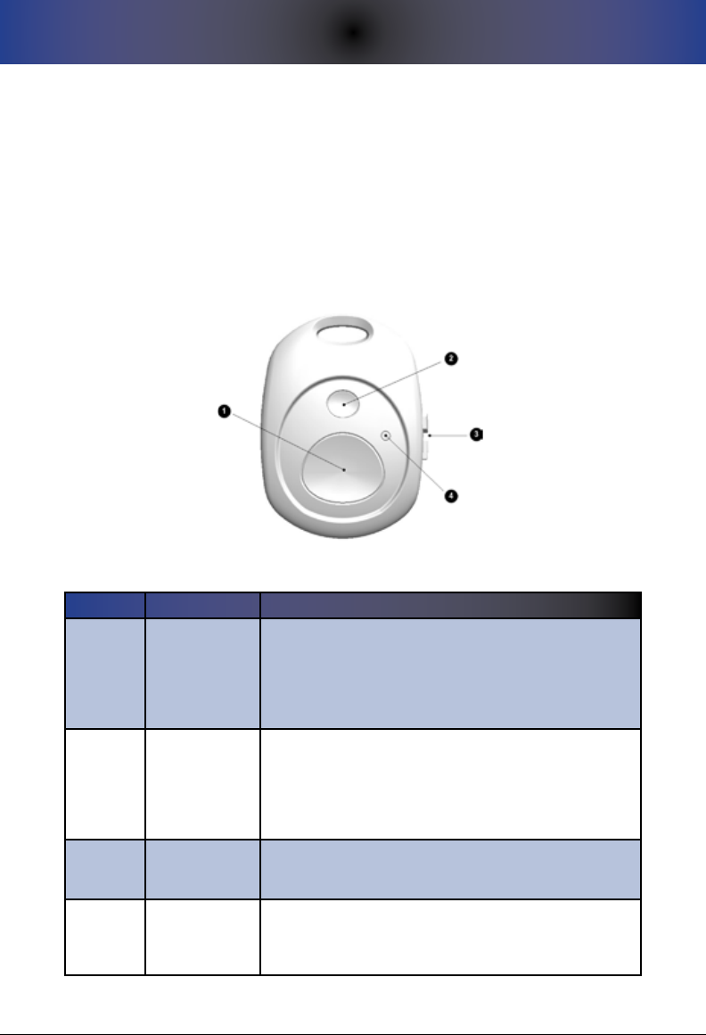
Pendant Front View
The front of the Pendant contains the controls/indicators that allow the user
to initiate the emergency call process or to cancel a previously-triggered
emergency call process. The Pendant design has been deliberately left
extremely simple with only two controls -- the large blue HELP/Emergency
button and a smaller gray CANCEL button. Each is described below.
Pendant Figure 4.
Pendant Controls and IndicatorsTable 1.
Re f # IT e M fUnCTIon
1HELP Button
The large blue HELP button on the Pendant is to be
pressed to trigger the emergency calling process. As an
added feature, if this button is pressed three times within a
5-second period, Prodigy will call 911 directly, skipping all
programmed numbers. This is known as the “Direct to 911”
feature.
2CANCEL Button
The small gray CANCEL button is to be pressed to stop/
cancel the emergency calling process. This functions
identically to the CANCEL button on the Console. You can
also use this button to test the connectivity between the
Pendant and the Console as well as the power level in the
battery within the Pendant.
3Opposing
Thumb Tabs
The opposing thumb tabs allow for ease of opening the
Pendant for battery replacement without the need for tools.
The Pendant uses a single CR2032 (3-volt lithium) battery.
4Signal LED
The red LED indicator illuminates after the HELP or CANCEL
buttons are pressed. This provides a visual indication to
the user that the wireless signal has been successfully
transmitted.

12
4. PENDANT CONTROLS AND INDICATORS
THIS PAGE INTENTIONALLY LEFT BLANK
5. GETTING STARTED: BASIC SETUP
13
5. geTTIng sTaRTeD: basIC seTUp
All users should start with Basic Setup for initial setup of the system. Basic
setup is sucient for a large majority of our users. Then, if you choose, you
can congure additional features. Basic setup of your Prodigy should not take
more than about 15 minutes as outlined here. For an abbreviated, yet eective,
instruction on Basic Setup, you can refer to the Quick Start Guide. In contrast,
this section contains the same information as that found in the Quick Start
Guide, yet provides additional detail.
For support during setup, you can call us at 610-410-7508 weekdays from
9:00 am to 5:00 pm eastern USA time or send us an email. An email to
support@LifelinkMedicalAlert.com with a description of your problem may be
addressed more quickly than a phone call. You can also visit our support page
at www.LifelinkMedicalAlert.com/support for the most recent version of this
Guide and other documentation, as well as for detailed troubleshooting guides.
if you have problems, please review the “Troubleshooting” section within this
Guide. Also, please feel free to access our forums for general discussion, tip
sharing, etc. Forums can be found at:
forums.LifelinkMedicalAlert.com
Setup of your Prodigy is guided by the “Setup Menu” through
pressing of keys on your phone. Please see Appendix D for a
“Quick Key” reference to the entire Prodigy Setup Menu.
Step 1: Connect your Prodigy Console
CAUTION: The phone jack on the back of the Console labeled
“TO LINE” is sensitive to high-voltage spikes from lightning. If
you live in an area where electrical storms occur frequently, we
recommend that you protect your system with a dual “Power
+ Phone” surge protection device, available at most home
stores.
Select a location for your system Console. Table top placement is 1.
optimal, though screw eyelets on the bottom of the unit allow for wall
mounting. Ensure that the surface is a hard surface; this allows for
unobstructed voice communications through the microphone located
on the bottom of the unit.
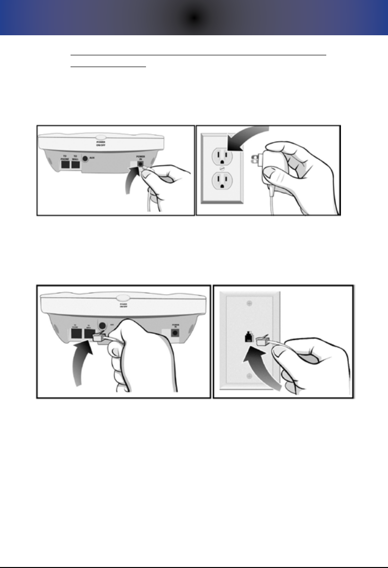
Now, connect the AC power adapter into the back of the Console into 2.
the power jack labeled “POWER IN.” Make sure you DO NOT connect
14
5. GETTING STARTED: BASIC SETUP
the AC power adapter into the jack labeled “AUX” as this could
damage your unit! Next, connect the other end of the power adapter
into an AC power outlet in your house that is NOT controlled by a
switch. See Figure 5 for an illustration of this step. Note that you will
NOT see any LED lights light up until you power your unit on later in
this process.
Connecting Prodigy to AC PowerFigure 5.
Insert the telephone cord into the jack on the back of the Console 3.
labeled “TO WALL.” Connect the other end into a working telephone
wall jack. See Figure 6 for an illustration of this step.
Connecting Prodigy to Your Phone JackFigure 6.
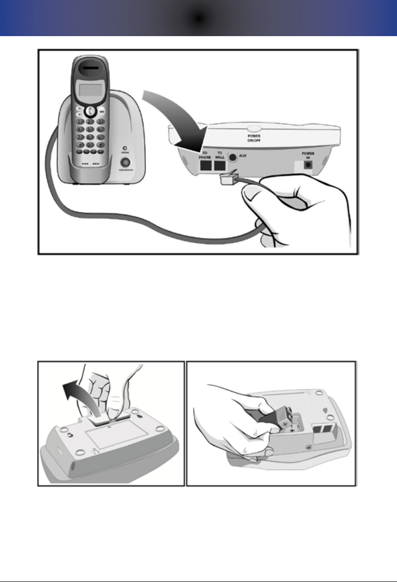
Connect a telephone to the back of your Prodigy into the jack labeled 4.
“TO PHONE.” If you do not have an available phone, skip this step. See
Figure 7 for an illustration.
5. GETTING STARTED: BASIC SETUP
15
Connecting Your Home Telephone to ProdigyFigure 7.
Open the battery compartment by depressing the clip with your 5.
thumbnail and lifting upward. Then, insert a fresh 9-volt battery (not
included) into the battery compartment as shown. Make sure you
follow the + and - polarity on the sticker. The 9-volt battery will keep
your system operational during a power outage. See Figure 8 for an
illustration of this step.
Inserting a New 9-Volt BatteryFigure 8.
Power on your system by pressing and holding the POWER ON/OFF 6.
button on the back of the unit for about one or two seconds. The
Console will power on and will play a message over the speaker with
instructions entering Setup mode.
If this is the rst time you are programming your Prodigy, minimum 7.
16
5. GETTING STARTED: BASIC SETUP
conguration is not yet in place. Minimum conguration requires
at least one phone number and at least one registered Pendant. To
indicate this situation, all indicator LEDs/lights will be blinking on the
Console.
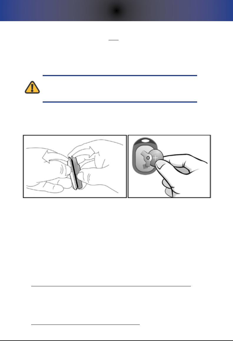
Step 2: Insert the Pendant Battery
CAUTION: When inserting the battery into the Pendant, do
NOT use tools! Doing so will damage the housing of the
Pendant resulting in a non-working Pendant!
Separate the halves of the Pendant using your thumbnails on the 1.
thumb tabs on the side of the Pendant. See Figure 9 for an illustration
of this step.
Inserting Pendant BatteryFigure 9.
Insert the provided 3-volt lithium CR2032 battery with the at side 2.
(marked with a “+” sign) facing up. Close the halves of the Pendant and
snap together..
Step 3: Enter Setup Mode
All setup of your system is done by using the numeric keypad on either a
directly-attached (Direct Setup method) or remote (Remote Setup method)
telephone. The next sections describe how to enter Setup mode through either
method:
Performing Setup From a Directly-Attached Phone (Direct Setup)
To perform Direct Setup, you must have a phone attached to the Console.
If this is the case, simply pick up this directly-attached phone handset and
press the SETUP button on the Console.
Performing Setup Remotely (Remote Setup)

5. GETTING STARTED: BASIC SETUP
17
In order to use Remote Setup, the system must be connected
to a working phone line.
Remote Setup is available with your Prodigy system. Remote Setup is
benecial, for example, if the individual programming the system cannot
physically be near the device or if a directly-attached telephone is not avail-
able for direct setup.
Note that, once in Setup mode, Setup will time out if a
keypress is not received from the phone within 30 seconds.
This is done to ensure that the system isn’t inadvertently left
in Setup mode. While this timeout is just an inconvenience for
Direct Setup, remote users may need to re-initiate the setup
process by re-coordinating with the system owner if a timeout
occurs.
To initiate setup remotely, execute the following:
Ensure that the phone line is not in use, and press (or coordinate to 1.
have someone press) the SETUP button on the Console.
A message will play instructing you to press the SETUP button again 2.
within 5 seconds.
The remote user then has up to 60 seconds to dial in to the system by 3.
calling the phone number associated with the line to which Prodigy is
connected. They will immediately be connected to the Setup Menu.
Step 4: Register the Pendant to the Console
As noted, all programming is guided by a series of voice menu
prompts, similar to that of a voice mail system.
From the Setup Menu, press 1. 1 for Basic Setup, followed by 1 for
Pendants. Then, select option 1 to “Register a Pendant.”
Follow the voice prompts. For your reference, the blue button on the 2.
Pendant is the HELP/Emergency button, and the smaller gray button is
the CANCEL button. (See Table 5 for more information).
If you are registering multiple Pendants, repeat the above steps to 3.
register each Pendant individually.
Things to Know About Pendants
A maximum of 12 Pendants can be used with your Prodigy system.•

18
5. GETTING STARTED: BASIC SETUP
The lanyard on your Pendant is engineered to break away in the event •
that it should get caught on something during a fall.
Your Pendant is engineered to be worn in the shower or bath tub. •
However, the Pendant is not intended to be submersed in water for an
extended period.
The Pendant and Console use the latest in frequency shift keying (FSK) •
wireless technology to enhance range and decrease the aects of inter-
ference. Your Pendants should have a range of up to 500 feet in open
air. However, the operating range of your Pendant depends on many
factors including intervening walls, electrical interference, or various
appliances such as vacuum cleaners, microwave ovens, mixers, coee
grinders, hair dryers and other sources of electrical noise around the
house. The system should cover your typical home and within a typical
yard.
To determine your eective Pendant-to-Console range, you can walk •
throughout your home and property and press the CANCEL button on
the Pendant every 10 feet or so. You will hear a chime (by default) on
the Console if you are within range in that area.
Step 5: Program Your Emergency Phone Numbers
You need touch-tone telephone service at the location where
Prodigy is installed. Because this is virtually 100% the case
today, this should not be an issue.
From the Setup Menu, press 1. 1 for Basic Setup, followed by 2 for
Emergency Numbers. From there, select 1 to “Add an Emergency
Number”.
Using your phone’s keypad, enter your rst emergency number 2. exactly
as it would be dialed from this location and press the # key. For
example, if you are programming a long distance number, you typically
need to start your number with a “1,” so make sure this is programmed
into your system as well. After the last digit is entered, press the # key
on your phone. The number will be saved into memory.
Program the remaining emergency numbers per the above 3.
instructions. Note that you can program a maximum of eight
emergency numbers.
To change or review phone numbers, follow the appropriate voice 4.
submenus within this menu.

5. GETTING STARTED: BASIC SETUP
19
\
Once minimum conguration has been met, all LED indicator
lights will return to their normal state. If any LED is still red,
this indicates a problem that must be resolved before moving
forward with the installation. For example, if the 9-volt battery
is low on power (or inserted improperly), the CONSOLE
BATTERY indicator LED will be ashing red.
Things To Know About Emergency Phone Numbers
If you wish to use 911 (or equivalent), you should program this number •
as the last number in your sequence. The reason for this is that, once a
call goes to 911, no further calls will be made. Prodigy has done its job.
For information on our “Direct to 911” feature (which bypasses all other
programmed numbers), please reference that section.
A maximum of 20 digits can be programmed for phone numbers. •
You can program up to a maximum of eight emergency numbers.•
When entering a phone number, enter it EXACTLY as it would be dialed •
from the location in which Prodigy is being used. For example, if the
number to be dialed is a long distance number, enter the number as
you would dial a long distance number from a regular phone from this
location.
If you need to program a pause within the number (i.e. if you need to •
dial a “9” from a hotel room to get an outside line, for example), each
press of the * key generates a 1-second pause.
Step 6: Record Your Outgoing Message (Optional)
During an emergency, the person who answers the call will hear your recorded
message. Recording your own personal outgoing voice message is optional,
however, since a default message will be used if you do not wish to record your
own. To record your own message, execute this step.
From the Setup Menu, press 1. 1 for Basic Setup, followed by 3 for
Recorded Message. Then, select option 1 to record your message.
Using your telephone, follow the voice prompts to record your 2.
message, pressing the # key when done. You DO NOT need to
include any home address information, unless you want to, because
this information will already be known by all parties, even 911.
Note that you can record approximately 20 seconds of speech, but you 3.
should try to keep your message under 10-12 seconds or so if possible.

20
5. GETTING STARTED: BASIC SETUP
Two examples of eective outgoing messages are:
“This is Mr. Brown. I’ve fallen and can’t get to
the phone. I live at 42 Barbara Drive in Wilmington
Delaware. The lockbox combination is 4856.”
“Hello, this is Edith King. I have had a medical
emergency and I need help right away. Please send
help now.”
The system automatically appends the following message onto the end
of all personally-recorded messages:
Please press 0 multiple times on your phone to communicate
by two-way speakerphone. This message will replay momen-
tarily.
If you like, you can listen to what you’ve recorded. From the “Recorded Message”
menu, press 3 to review.
Things To Know About Your Recorded/Outgoing Message
The recorded emergency message, sometimes referred to as the “Out-•
going Message,” is the message you want the call recipient(s) to hear in
the event of an actual emergency.
You do NOT need to record your own message if you choose not to. In •
this case, the default system message will be used.
You have up to 20 seconds of record time if you wish to record your •
own emergency message. Optimally, you should try to keep your mes-
sage as short as possible while still providing any necessary information
such as person’s name, the fact that there is an emergency, and special
instructions such as the location of the door key, lockbox combination,
etc.
If your call goes to 911, by default, your recorded message will not play; •
two-way communications will be established immediately.

5. GETTING STARTED: BASIC SETUP
21
At this point, Basic Setup is now complete and your
system is fully operational! You may wish to consider
optional features as described in the next chapter. However,
prior to any optional conguration, it is recommended that
you run a manual system test. For instructions, please refer to
the section titled “Testing Your System” in the chapter titled
“Operating Your LifeLink Prodigy”.
Caregivers should strongly encourage the user to try to pay
attention to the system’s LED indicator lights, if possible. If any
light is red, the user should notify someone and/or resolve the
problem themselves. A red LED indicator indicates a problem
that needs to be addressed. All green means everything is ok.

22
5. GETTING STARTED: BASIC SETUP
THIS PAGE INTENTIONALLY LEFT BLANK

6. OPTIONAL FEATURES SETUP
23
6. opTIonal feaTURes seTUp
Your Prodigy system contains optional features which can be enabled
to enhance your use of the system. The following sections describe the
procedures for activating the optional features built into the system.
However, before discussing optional features, it is important to review some key
terms that some of these optional features are based upon. These key terms
include the “Primary Contact”, the “Test Required Interval”, and the “System
Clock”. Each is described in the sections that follow.
The Primary Contact
The term “Primary Contact” refers to the telephone number of the individual
who is primarily responsible (or who has taken primary responsibility) for the
user of the Prodigy system. Setting the Primary Contact is not mandatory.
It is only needed if you wish to activate optional features which need the
Primary Contact - the Console Low Battery notication and the Failed Pendant
Notication. Additionally, test functions (automatic and/or manual) can be set
to go only to the Primary Contact, though by default, test calls will follow the
emergency calling process.
Test Required Interval
By default, your Prodigy system requires that a test (manual or automatic) be
conducted at least once every 30 days. Though we use the term “Test Required”
to refer to this, there is nothing in the system’s operation that actually mandates
a test; it is more that the system “recommends” that a test be run.
You can modify the number of days that are allowed to elapse before a test is
required/recommended. This is known as the “Test Required Interval”. Once
the number of days runs down to zero, the TEST REQUIRED indicator LED on
the Console will begin ashing red in an attempt to remind the user that a test
should be executed. Failure to run routine tests has been found to be a problem
area in the use of almost all medical alert systems.
To set or review the Test Required Interval, execute these steps:
From the “General Settings” menu option within Setup, select option 1.
2 for “Test Required Interval”.
Follow the voice prompts to 1) set the test required interval, 2) review 2.
the interval, or 3) review the number of days until the next test is
required.
Setting the System Clock

24
6. OPTIONAL FEATURES SETUP
Some optional features are based on a reasonably-accurate system clock,
though none actually requires it. An accurate clock is more of a convenience
than a requirement. To set the clock, execute these steps:
From the “General Settings” menu within Setup, select option 1. 3 for
“System Clock”.
Follow the voice prompts to enter the system time.2.
Automatic Test Call Setup
The Automatic Test Call is a test call that will be automatically executed at the
time of day you specify. The benet of the automatic test call is that you do not
need to remember to test the system; it remembers to it for you.
To program the Automatic Test Call function, execute these steps:
From the Setup Menu, press 1. 4 for “Test Call Setup.”
From the “Test Call Setup” menu, press 2. 1 for Automatic Test Call
Settings.
Follow the voice prompts to add, change, delete, or review the current 3.
settings for automatic test calls.
By default, your system does not execute automatic test calls.
If you activate the Automatic Test Call function, you have the
option of overriding the system defaults for the siren and the
time-to-call. The default for the siren is to NOT sound the siren
during a test. The default time of day to run the test is 10:00am
local time.
Things to Know About Automatic Test Calls
The automatic test call will • only execute if a test is required (if the TEST
REQUIRED light is ashing red). A test is required if 30 days or more have
elapsed since the last successful test call, the default setting.
If you wish to have the test call go ONLY to your Primary Contact, you •
must have the Primary Contact phone number programmed into your
system prior to setting this option.
This function is time-of-day dependent and, therefore, the system •
must have a reasonably-accurate system clock. Once you set the clock
through the Setup Menu, the clock will accurately keep time. The clock
will only lose its time if both power sources fail at the same time for
more than approximately two days.
Daylight Savings Time, which is used within the United States, has not •
been programmed into this version of the system, so please be aware

6. OPTIONAL FEATURES SETUP
25
that test calls could possibly be made 1 hour ahead or 1 hour behind
the expected time if the clock is not manually adjusted. Since a 1-hour
dierential is not a critical dierence for this function, this is not a prob-
lem.
Notification Setup
Your Prodigy system oers the capability to make an outbound telephone
call to the Primary Contact to inform them of a particular problem (or
imminent problem) with the system. These dialout functions are referred to as
“Notications” within the system. While audible and visual alerts are built into
the system to let the user know of a problem or situation, these notication calls
provide additional assurance that someone outside of the user’s home is aware
of the situation.
There are three basic kinds of notications:
Console Low Battery Notication•
Failed Pendant Notication•
Social Safety Notication•
Setup for each is described in the sections that follow.
Console Low Battery Notification Setup
Your Prodigy system is engineered to be able to run o of the 9-volt battery
in the Console in the event that the primary AC house power fails. However,
if the backup battery fails along with an AC power outage, the system will not
operate. To ensure that this does not occur, while the CONSOLE BATTERY light
will ash red, you can set the system to make an outbound telephone call to
your Primary Contact.
To program the Console Low Battery Notication function, execute these steps:
From the Setup Menu, press 1. 5 for “Notication Setup.”
From the “Notication Setup” menu, press 2. 2 for “Console Low Battery
Notication.”
Follow the voice prompts to add, change, delete, or review the current 3.
settings for this function.
Things to Know About Console Low Battery Notication
You must have your Primary Contact phone number programmed in •
order to use this function.
After this function has been programmed, the notication is automatic •
if a low battery is been detected, and the call will be made at the pro-

26
6. OPTIONAL FEATURES SETUP
grammed time of day. The default time for the notication is 3:00pm
local time.
This function is time-of-day dependent and, therefore, the system •
must have a reasonably-accurate system clock. Once you set the clock
through the Setup Menu, the clock accurately keeps time. The clock
only loses its time if both power sources fail at the same time for more
than approximately two days.
Daylight Savings Time, which is used within the United States, has not •
been programmed into this version of the system, so please be aware
that test calls may be made 1 hour ahead or 1 hour behind the expect-
ed time if the clock is not manually adjusted. Since a 1-hour dierential
is not a critical dierence for this function, this is not a problem.
Failed Pendant Notification Setup
Your Prodigy system is engineered such that the Pendant sends periodic status
reports to the Console. Among other things, these status reports communicate
the power level of the battery in the Pendant. If the power level gets too low,
the Pendant is marked as “at risk”, and the PENDANT STATUS indicator light on
the Console will ash red.
Similarly, a Pendant is marked as “failed” if the Console does not receive
consistent status reports. For example, if a Pendant simply stops working for
whatever reason, the PENDANT STATUS indicator light will begin ashing red.
To program the Failed Pendant Notication function, execute these steps:
From the Setup Menu, press 1. 5 for “Notication Setup.”
From the “Notication Setup” menu, press 2. 1 for “Failed Pendant
Notication.”
Follow the voice prompts to add, change, delete, or review the current 3.
settings for this function.
Things to Know About Failed Pendant Notication
After this function has been programmed, the notication is automatic •
if an at-risk or failed Pendant is detected, and the call will be made at the
programmed time of day. The default time for the notication is 1:00pm
local time.
If the PENDANT STATUS indicator light on the Console is ashing red •
-- and you have multiple Pendants -- one of them is having the problem.
To determine which Pendant is having the problem, simply press the
CANCEL button on each Pendant. The normal chime will sound if the
Pendant is OK. Otherwise, an audible message will sound on the Con-

6. OPTIONAL FEATURES SETUP
27
sole indicating that this is the problem Pendant. Obviously, if you get
no response from the Console, that Pendant is having the problem.
This function is time-of-day dependent and, therefore, the system •
must have a reasonably-accurate system clock. Once you set the clock
through the Setup Menu, the clock accurately keeps time. The clock
only loses its time if both power sources fail at the same time for more
than two days.
Daylight Savings Time, which is used within the United States, has not •
been programmed into this version of the system, so please be aware
that test calls may be made 1 hour ahead or 1 hour behind the expect-
ed time if the clock is not manually adjusted. Since a 1-hour dierential
is not a critical dierence for this function, this is not a problem.
Social Safety Setup
Past experience in the industry indicates that some caregivers wish to have the
capability of ensuring that the user presses a button on their system in response
to an alarm-clock-like sound that occurs daily. We call this feature the “Social
Safety” function.
If this feature is activated, when the time of day programmed into the system
for this function approaches, the system will sound the alarm-clock-like alarm.
If the CANCEL button (either on the Pendant or on the Console) is not pressed
within 15 minutes, the system will execute the emergency calling process as
if it were an actual triggered emergency. This function is useful if the user has
become unable to press the HELP button on their Pendant to call for help.
To program the Social Safety Notication function, execute these steps:
From the Setup Menu, press 1. 5 for “Notication Setup.”
From the “Notication Setup” menu, press 2. 3 for Social Safety
Notication.
Follow the voice prompts to add, change, delete, or review the current 3.
settings for Social Safety Notication.
Things to Know About Social Safety Notication
You should only activate this function if you are sure that 1) the user •
understands this function and what they are required to do, and 2) the
user is home at all times; that is, they will not be traveling overnight
away from the Console. If they will be traveling overnight and this func-
tion is turned on, you should power down your Prodigy (and take the
9-volt battery out) prior to traveling. Alternatively, you can temporarily
turn this function o.

28
6. OPTIONAL FEATURES SETUP
If the CANCEL button is pressed within the 15-minute period (either on •
the Pendant or the Console), the alarm clock sound will stop sounding,
and the function will be re-scheduled for the next day. If the CANCEL
button is not pressed within the 15-minute period, the system will
execute the emergency call process.
Note that this function SHOULD NOT be used as a regular alarm clock as •
the Console may be too far from the user for the user to hear the alarm
bell during sleep.
This function is time-of-day dependent and, therefore, the system •
must have a reasonably-accurate system clock. Once you set the clock
through Setup, the clock accurately keeps time. The clock only loses its
time if both power sources fail at the same time for more than two days.
Daylight Savings Time (DST), which is used within the United States, •
has not been programmed into this version of the system, so please be
aware that the “wake up” time of day may be 1 hour ahead or behind
the given DST begin/end unless the clock is manually adjusted. Since a
1-hour dierential is not a critical dierence for this function, this is not a
problem.
Cancel Button Confirmation Sound: Chime or Barking Dog
You can change the sound played when the CANCEL button is pressed on
the Pendant or the Console. This sound is referred to as the “Cancel Button
Conrmation Sound.” By default, when you press the CANCEL button on the
Pendant or the Console, the Console will sound a double-chime. Alternatively,
you can program the system to sound a barking dog.
To program the sound which plays when you press the CANCEL button, execute
these steps:
From the “General Settings” menu within Setup, select Option 1. 5
“Override the Cancel Button Conrmation Sound”.
Follow the voice prompts to select a chime or a barking dog.2.
Setting the Cancel Button Conrmation Sound to “Barking Dog”
may be benecial for individuals who may wish to ward o
potential intruders. Each press of the CANCEL button cycles
through one of three dierent dog bark patterns for a more
natural-sounding dog bark.
6. OPTIONAL FEATURES SETUP
29
If you have selected Barking Dog, and you actually have the
occasion to use it, you should use the CANCEL button on
the Console rather than on the Pendant. Though both can
be used, using the CANCEL button on the Console will save
battery power in the Pendant.
Override the Default 911 Emergency Number
Engineers of the Prodigy system recognize that 911 is not the emergency
number used for all countries or locations. This option allows the user to
override the 911 number; this new number becomes the “911 Equivalent”
number. It is important to understand that Prodigy will skip 911 or the
programmed 911-equivalent number during test calls.
Under normal circumstances, you do not need to be concerned
with this setting if you will be using your Prodigy system within
the United States or Canada.
To override the 911 emergency number, execute these steps:
From the “General Settings” menu within Setup, select Option 1. 5
“Override the Default 911 Emergency Phone Number for Your Country
or Location.”
Follow the voice prompts to override the default 911 emergency 2.
number.
Additionally, within this menu option, you can override the default setting to
either play -- or not play -- your recorded message to 911 or equivalent. By
default, your recorded message will NOT play to 911. Note that, if you wish to
override the default, you should check with your local 911 emergency services
personnel to be sure that they authorize a pre-recorded message as part of the
emergency call.

30
6. OPTIONAL FEATURES SETUP
THIS PAGE INTENTIONALLY LEFT BLANK

7. OPERATING YOUR LIFELINK PRODIGY
31
7. opeRaTIng yoUR lIfelInK pRoDIgy
This section provides information on the use and operation of your new Prodigy
system.
Emergency Operation
Triggering an Emergency: What to Expect
For all intents and purposes, operating your Prodigy is as simple as pressing
the blue HELP button one time on the Pendant or the Console. This is all you,
or more importantly the user, really ever absolutely need to know about the
system; this simplicity is often comforting to most users of our system.
That said, understanding the process is helpful. As stated, to trigger an
emergency, simply press the blue HELP button either on the Pendant or the
Console. The siren, if programmed to sound (the default setting will sound the
siren) will be heard over the speaker for approximately ve seconds. If you have
overridden the default, instead of the siren, you will hear ve beeps over the
speaker for ve seconds. After this ve-second period, you will hear dial tone,
and you will then hear the sound of digits being dialed. The call proceeds.
You can control the volume of the speaker (and thereby the
siren) in your Prodigy using the volume control knob/wheel
on the right hand side of the unit. Be careful not to force the
volume position past the extreme low and/or extreme high
volume levels to avoid breaking the knob. Typically, once set, it
is rarely necessary to adjust it.
Once the emergency call is answered, the recorded message (or default system
message if you didn’t record your own message) will begin playing. Note that,
depending on how quickly the called party answers, they may only hear the tail-
end of the recorded message. This is not a problem as the message will replay
after a few seconds.
The following system message will be added onto the end of the user’s
recorded message:
Please press zero on your phone to begin
two-way communications.
The called party will press zero on their phone. The called party should
understand that they may need to press zero more than once in order for
Prodigy to be absolutely sure that an actual person has responded to the call.
32
7. OPERATING YOUR LIFELINK PRODIGY
Two-way communication will then be established, and the called party will hear
the following message:
Two way communication has been established.
Press the star key to end the call.
When the called party wishes to end the call, they must press the * (also
known as the “asterisk” or “star”) key on their phone. Prodigy will then hang up
and the system will return to standby mode.
Direct to 911: Triggering an Emergency Call Directly to 911
Though the process described in the previous section is sucient for the
majority of emergency situations, there may be times when the user may nd
it necessary to bypass the normal emergency calling sequence and go directly
to 911 (or equivalent). Prodigy is engineered to call 911 directly if the blue
HELP button on the Pendant is pressed three (3) times within a 5-second
period. Doing so instructs Prodigy to bypass all programmed numbers and call
911 (or equivalent) directly, even if 911 is not in the calling sequence.
It is NOT necessary to have 911 in your calling sequence (your
list of programmed numbers) to utilize the “Direct to 911”
feature.
It is important to understand that, depending on the physical and/or cognitive
capabilities of the user, you may choose not to communicate this feature, and
opt instead to “keep things simple” for the individual using the system.
What if the Emergency Call is not Answered?
If a particular emergency call is not answered, or the call is answered, but the
zero key is never pressed (this can happen if an answering machine answers the
call) the system will automatically hang up and begin calling the next number in
the sequence. If all numbers are called, and the system still has not received the
zero keypress, the entire process is repeated until a successful zero is received.
Cancelling the Emergency Call Process
To cancel the entire emergency call process, simply press the CANCEL
button either on the Pendant or the Console. You will hear a “double chime”
conrmation sound (default setting) on the Console that lets you know that the
cancel request was successful.
Two-Way Communication

7. OPERATING YOUR LIFELINK PRODIGY
33
Once the zero key is pressed by the person receiving the call, two-way
communication will be established. However, it is important to understand that
the ability of Prodigy to “pick up” the voice of the person in distress depends
on simple laws of physics and how well their voice will carry throughout the
home. In other words, obviously, a weak voice will not pick up as well as a
loud, booming voice. That said, any verbal communication heard should be
considered a secondary benet of the system, with the primary benet being
the fact that an emergency call was made.
Disconnecting the Emergency Call
During an established two-way call, either party can hang up/disconnect the
call as follows:
For the person who received the call, simply press the star key • * on
their telephone.
If the person receiving the call forgets to press the * key to end the call, •
Prodigy will automatically disconnect the call and return to standby
mode if silence is detected on the line for 30 seconds or more.
For the person in distress, simply press the gray CANCEL button on the •
Pendant or the white CANCEL button on the Console.
Things to Know About the Emergency Call Process
If the system is accidentally triggered, simply press the gray CANCEL •
button on the Pendant or the white CANCEL button on the Console.
This immediately cancels/stops the entire process.
Once the zero key is successfully pressed by the call recipient, NO fur-•
ther calls are made. Prodigy has done its job.
If an answering machine answers the call, your system disconnects the •
call after playing the recorded message twice, since a zero key would
not have been received. The system will then automatically move on to
the next number in the sequence. If a zero keypress is not received for
any of the emergency numbers called, Prodigy re-initiates the full calling
process beginning with the rst number in the sequence (the number
in memory location 1.
The Notification Process
Your Prodigy system has the ability to make an outbound telephone call to the
programmed Primary Contact informing them of a failure or imminent failure of
a critical system component. The sections that follow describe how each of the
various notication processes works.
Console Low Battery Notification Process

34
7. OPERATING YOUR LIFELINK PRODIGY
If you have programmed the Console Low Battery Notication function, the
Primary Contact will be called in the event of a situation where the Console’s
backup battery power level has dropped to an unacceptable level. The system
processes the notication as follows:
At the programmed time of day, the system initiates the notication 1.
call by playing a message over the speaker which informs the user that
a notication call is about to take place.
The system initiates a telephone call to the Primary Contact, and the 2.
Primary Contact’s telephone rings.
When the Primary Contact answers the call, a system-generated 3.
pre-recorded message plays indicating that the backup battery in
the Console is low on power. They are instructed to press “0” on their
phone to conrm the notication call.
Once the Primary Contact presses “0”, the system will hang up.4.
Things to Know About Console Low Battery Notication
After this function has been programmed, the notication will be auto-•
matically executed if a low Console battery condition is detected. The
notication call is made at the programmed time of day.
The notication call will continue daily at the programmed time of day •
until the problem is resolved.
This function is time-of-day dependent and, therefore, the system •
must have a reasonably-accurate system clock. Once you set the clock
through the Setup Menu, the clock accurately keeps time. The clock
only loses its time if both power sources (AC and backup battery) fail at
the same time, and the failure continues for more than approximately
two days.
Daylight Savings Time, which is used within the United States, has not •
been programmed into this version of the system, so please be aware
that outbound calls may be made 1 hour ahead or 1 hour behind the
expected time unless the clock is manually adjusted. Since a 1-hour dif-
ferential is not a critical dierence for this function, this is not a problem.
Failed Pendant Notification Process
The Failed Pendant Notication process makes an outbound telephone call to
your Primary Contact in the event that the system has detected a failed Pendant
or the Pendant has reported a low battery. This function is essentially identical
to the Console Low Battery Notication process described above. Refer to this
section for details.

7. OPERATING YOUR LIFELINK PRODIGY
35
Social Safety Process
For information on the Social Safety notication process, see the corresponding
section in the “Optional Features Setup” portion of this Guide.
Checking System Status
Your Prodigy has been designed to make it easy to use and, equally-important,
to ensure that it is always in good working order. This is made possible through
a host of facilities including the use of visual status indicators (LED indicator
lights), audible warning messages, and notication calls to outside individuals.
Visual Status Indicators
Visually, if any LED indicator light is red, it is an indication that there is a problem
with the corresponding function. The user should understand that, if any LED
lights are red, the situation must be resolved either by themselves or through
outside help. For example, if the CONSOLE BATTERY indicator light is red,
replacing the 9-volt battery with a fresh 9-volt battery will resolve the problem,
and the ashing red indicator light will turn solid green.
The LED indicator lights noted in the table below are found on the top/face of
the system. As noted, in a normal and healthy state, all indicator LED indicator
lights should be solid green. This means that:
The system is running on AC house power.•
The backup battery in the Console is good.•
The phone line is in good working order (and not in use or o-hook)•
All registered Pendants are successfully reporting to the Console.•
A system test is not required or needed at this time.•
Visual Status IndicatorsTable 5.
leD In D I C a T o R sT a T U s
AC POWER
Solid Green = AC power OK
Blinking Green = AC power out; system running on backup
battery.
CONSOLE BATTERY
Solid Green = Console backup battery power OK.
Blinking Red = Console backup battery power low; battery must
be replaced.
PENDANT STATUS
Solid Green = All registered Pendants are reporting to the Console
and their battery is OK.
Blinking Red = At least one registered Pendant has a problem
(Pendant not reporting or battery low).

36
7. OPERATING YOUR LIFELINK PRODIGY
leD In D I C a T o R sT a T U s
LINE STATUS
Solid Green = Phone line is OK.
Blinking Red = There is a problem with the phone line or the
phone line is in use.
TEST REQUIRED Solid Green = A system test is not needed at this time.
Blinking Red = A system test is recommended at this time.
Audible Status Messages
Your Prodigy system will sound various audible warning messages in
conjunction with critical status functions. Audible status messages have been
engineered for the most critical of functions such as a problem with the phone
line or the backup battery is low on power. These audible warning messages
are played over the Console’s speaker in an eort to provide a second warning
mechanism to the user in addition to the LED indicator lights.
Problem with the Phone Line
In the event of a problem with the phone line, or the phone line is in use or o-
hook, an audible message will play every 15 minutes over the system’s speaker
that informs the user of this condition. There is no specic conguration setting
required to turn this feature on or o; the feature is always active if the situation
is detected. This feature cannot be disabled.
AC Power Problem
In the event of a failure of AC power (regular house power), an audible warning
message will play every 15 minutes to inform the user that the system is running
on backup battery. This is particularly useful in the event that the AC power
cord has been accidentally removed from the wall socket. There is no specic
conguration setting required to turn this feature on or o; the feature is always
active if the condition is detected. This feature cannot be disabled.
System is Running on Battery and Battery Power Level is Low
In an extended power outage situation, the system will be kept running using
the Console backup battery. In the event that the backup battery power
level becomes low, an audible warning message will play every 15 minutes
instructing the user to replace the backup battery. If this situation occurs, you
can simply hot-swap the old battery for a new one and the system will continue
operation during the power outage.
There is no specic conguration setting required to turn this feature on or o;
the feature is always active if the condition is detected. This feature cannot be
disabled.

7. OPERATING YOUR LIFELINK PRODIGY
37
Pendant Battery Power Level is Low
In response to the CANCEL button being pressed on the Pendant, if the
battery power level is low in the Pendant, an audible message will play over
the Console’s speaker informing the user of the problem. For information on
replacing the battery in the pendant, refer to the section titled “Changing the
Battery in the Pendant” in the “Maintenance of Your System” chapter in this
Guide.
Checking System Status through a Directly-Attached Phone
While system status is evident visually, through observing the LED indicator
lights and/or hearing audible messages, it may be benecial to hear a summary
of the system’s status. You can obtain a full status of your system through your
directly-attached telephone using the “System Status” menu option.
If you do not have a directly-attached phone, refer to the next section for
checking status remotely.
To execute status checking, execute the following procedure:
Pick up the directly-attached phone, and press the SETUP button on 1.
the Console.
At the Setup Menu, press 2. 6 for “System Status”. Select the system
component you wish to review.
Checking System Status Remotely
For those who either do not have a directly-attached phone or for those who
are remote and do not have direct access to visual and/or audible status
indicators, remote status checking can be used.
Note that remote access will time out if a keypress is not
received from the phone within 30 seconds. This is done to
ensure that the system isn’t inadvertently left in Setup mode.
To execute remote status checking, perform the following procedure:
Assuming you are the remote person, call the in-home user and let 1.
them know that you wish to check the status of the system. Inform
them to press the SETUP button twice in a row after you hang up with
them.
Then, within 60 seconds, the remote user will dial the phone number of 2.
the line to which Prodigy is connected. Prodigy will answer the call and
you will be immediately connected to the Setup Menu as if you were
local to the system.

38
7. OPERATING YOUR LIFELINK PRODIGY
At the Setup Menu, press 3. 6 for “System Status”. Select the sub-option
of the system component you wish to review.
Testing Your System
Testing Strategy
It is highly recommended that you adhere to a test discipline whereby you are
routinely testing your Prodigy. One of the biggest problems with competitor
(and legacy) systems is that the system fails to work in an actual emergency due
to a problem that was never identied and resolved. These deciencies were a
motivating factor behind many of the checks and balances built into Prodigy.
One of the checks that you can activate is the automatic test call. Activating this
function and observing that automatic test calls are successful will go a long
way to ensuring the system will be there for you when it’s needed.
While programming the automatic test call function is a sound component to a
good testing strategy, there is still no substitute for an actual periodic manual
test call (initiated by the “RUN A TEST” button on the Console). The execution of
a manual test call is the more comprehensive of the two testing methods due
to the fact that a manual test is closest to a real emergency operation due to the
fact that it tests the full end-to-end process - from the wireless Pendant, to the
system, through the public telephone network, and out to the call recipient.
A mix of automatic test calls along with a periodic manual test call could be
considered the best testing strategy.
A Note About the TEST REQUIRED Indicator LED
As noted throughout this Guide, the system requires that a test call (manual or
automatic) be conducted at least once every 30 days, by default. While the term
“required” is used, it is eectively a “test recommended” indication. It is termed
“required,” though, to stress the importance of routinely ensuring a successful
system test.
The default setting of 30 days can be modied to any number of days between
1 and 30. This is known as the “Test Required Interval”. For example, a Test
Required interval setting of “2” would mean that Prodigy would execute a test
call every other day. If a successful test is obtained (the call recipient presses
the 0 key in response to the test message), the TEST REQUIRED indicator LED on
the Console will turn solid green. If a successful test is not obtained during the
Test Required interval (30 days by default), the TEST REQUIRED indicator light will
begin blinking red.

7. OPERATING YOUR LIFELINK PRODIGY
39
Running a Test Manually
The manual test call process is the most true-to-life system test, because it tests
the full end-to-end process - from the Pendant, to your Prodigy, through to the
public phone system, nally to the remote person receiving the call. This test
thereby fully-simulates a true emergency. The execution of the manual test call
process is as follows.
Contact the individual who is rst in the call list and let them know 1.
you will be running a test. This person will be referred to as your “test
partner”.
On the Console, press the RUN A TEST button. 2.
The system will respond by requesting that you press the blue HELP 3.
button on your Pendant. Do so. This will initiate the test.
The system will begin the calling sequence and will follow the default 4.
settings (whom to call, sound the siren, etc). So, by default, Prodigy
will sound the siren, and it will call the rst number in your emergency
call list. Note that, if you wish to change these settings, you can do so
through the Setup Menu.
Then, over the system’s speaker, you will hear the digits that are about 5.
to be dialed. The number will then be called.
The phone at your test partner’s location will ring, and they will answer 6.
it.
When the phone is answered, your test partner will hear the system-7.
generated test message that informs them to “Please press 0 to
activate two-way communications.” They will do so. You will then hear
the message “Two way communication has been established. Press the
star key to end the call.” You and your test partner can now conduct
two-way communication.
Instruct your test partner to press the 8. * key to end the call.
Alternatively, you can end the call yourself by pressing the gray CANCEL
button on your Pendant or on the Console.
911 (or equivalent) will NOT be called during a test call (manual
or automatic), even if it is in your call list.
Running a Test Automatically
Through the Setup Menu, you can instruct the system to execute automatic test
calls. An automatic test call is one that is initiated automatically by the system
with no user action required. This sort of test is benecial, for example, for those
who may be prone to forget to run a manual test or for those who simply wish
not to have to remember to run one.

40
7. OPERATING YOUR LIFELINK PRODIGY
By default, if activated, the automatic test call will run every 30 days. The default
time of day to execute the automatic test call is 10:00am local time.
The operation of the Automatic Test Call function is as follows:
At the specied time of day, the system will initiate the test call. 1.
An audible message will play over the Console’s speaker informing the 2.
user that a test call is about to take place.
The system will then begin the test call and will follow the settings 3.
that you have programmed through the Setup Menu. By default, the
Automatic Test Call process will initiate at 10:00am and will follow your
emergency call list. 911, if programmed, will not be called during a
test.
Things to Know About the Test Call Process (Manual and Automatic)
If the number of days since the last test reaches 30 days (by default), the •
TEST REQUIRED indicator light will turn from solid green to blinking red.
If an answering machine answers the test call, the system will discon-•
nect the call after playing the message twice since a zero will not have
been received. Prodigy will then automatically move to the next num-
ber in the sequence, unless the default has been overridden to have the
test call go to the Primary Contact.
Once the test call is answered, and your test partner presses the zero •
key, no further calls will be made.
If 911 (or equivalent) has been programmed into the call list, this num-•
ber will not be dialed during a test call.
The system-generated message that is played to your test partner will •
indicate that this is a test call (it is not an actual emergency).
If the test call is successful (the zero key is pressed by your test partner), •
the TEST REQUIRED indicator light will go from blinking red to solid
green. Another test will not be required for another 30 days (by default).
You can nd out the number of days remaining until the next test is •
required through the “General Settings” menu option, submenu option
#2, “Set or Review Test Required Interval”.

8. MISCELLANEOUS FUNCTIONS
41
8. MIsCellaneoUs fUnCTIons
Power On
To power on your LifeLink Prodigy, press and hold the Power On/O button
(located on the back of the unit) for at least 1 second. For new installations, after
Power On, all LEDs will ash indicating that minimum conguration has not yet
been met.
Power Off
Typically, you will always want your Prodigy to be powered on. However,
there are certain circumstances where you may wish to power the unit o. For
example, if you will be storing the unit, and it will be unused for an extended
period, a power o is appropriate.
Prodigy engineers have deliberately designed the “Power O” operation such
that the action requires clear intent to power the unit o (an accidental bump of
the button will not power the unit o). To power o your LifeLink Prodigy, press
and hold the Power On/O button (located on the back of the unit) for at least 5
seconds until you hear the audible message “Goodbye”. All LED indicator lights
go out.
After powering o, you should remove the unit from AC power and the phone
line. You should remove the 9-volt battery as well.
Reset/Reboot
In the event that your system appears to be frozen or hung, one or more LED
lights are either out or ashing randomly, or the system just seems to be acting
strangely, it is possible that the system may have caught a voltage spike either
through the phone line or the power line. In these cases, you can reboot your
system, similar to that which you would do for a computer. To do this, take a
paper clip, tooth pick, or similar tool, and insert it into the hole on the bottom
of the Console labeled “RESET.” Press and hold the reset button for about 5
seconds, then release. The system will reboot. Note that this function does NOT
aect the conguration of your device; it merely reboots the system. However,
the system clock will be reset to 12:00am after a reset function. So, if you use
functions that use the system clock, like automatic test calling, notications, or
social safety, for example, you should reset the clock to the correct time after a
reset function.
Using a Telephone That is Connected to Your Prodigy
If you wish to use a telephone with your Prodigy for making phone calls, simply
connect it into the jack on the back labelled “TO PHONE”. Once connected, you

42
8. MISCELLANEOUS FUNCTIONS
can use the phone as you normally would. Your phone will even work if your
Prodigy Console is powered down.
Line Seize Functionality
Prodigy has the ability to take control of, or to “seize”, your phone line and make
an emergency call in the event of an accidental o-hook situation or if the
phone line is otherwise in use within the home. The only restriction to the use
of this function is that the phone in use must be the one connected to Prodigy.
To ensure that this restriction is met, we suggest purchasing a multi-handset
cordless phone system. These systems have a Master phone handset and one
or more Satellite phones. Once purchased, all you would need to do is to
connect the Master to your Prodigy Console and you are done. In this way, if
any of the phones in the cordless phone system are left o hook anywhere in
the house, Prodigy will be able to seize the line and make an emergency call.
Reset to Factory Defaults
You can reset your system to factory defaults by selecting the “System Status”
option from the Setup Menu and select 0 to reset the system to factory defaults.
See “Appendix B” for factory default settings.

9. PRODIGY OPERATION DURING A POWER OUTAGE
43
9. pRoDIgy opeRaTIon DURIng a poWeR oUTage
Your Prodigy system is designed to continue operating even in the event of
a power outage. However, this assumes that your phone service stays active
during a power outage. Many voice over IP (VoIP) or digital phone services
have a limited availability due to their battery restrictions. If your phone service
is considered a digital/VoIP phone service such as Comcast, Verizon FIOS,
Brighthouse, etc., check with your provider for operation of the phone service
operation during a power outage.
CAUTION: If you are using a standalone VoIP service such as
Vonage, Ooma, MagicJack, Nettalk, etc., Prodigy’s ability to
make a phone call is completely dependent on the availability
of your Internet connection. If you are using a standalone VoIP
service, you should consider activating automatic test calling
so that you are aware of any outage. In fact, a daily test would
not be unreasonable. Additionally, you must ensure that you
have successfully registered your VoIP service location/address
with 911. Most VoIP providers mandate that you do this.
LED Indicator Lights During a Power Outage
In an eort to retain backup battery power during a power outage, all LED
indicator lights go dark/out except for the AC POWER indicator LED, which will
blink green.
Audible Voice Message Warning During a Power Outage
During a power outage, the system will play a voice message every 15 minutes
informing the user that they are running on backup battery power. This is also a
useful feature in the event that the system has been accidentally removed from
AC power.
For Extended Power Outages
Your Prodigy will remain powered up and operational using a 9-volt backup
battery for up to 20 hours, assuming a fresh/new battery. However, there can be
times where an extended power outage occurs. In preparation for such events,
we recommend keeping a supply of fresh 9-volt batteries on-hand. Also, check
with your phone service provider for their runtime in an extended power outage
situation. For most voice over IP phone service providers, their equipment will
run out of backup power well before Prodigy will. It may be a good idea to
request extended battery power for your phone equipment from your provider.
Optimally, switching to a traditional phone service will ensure that your phone
line is always active -- even during an extended power outage -- since the
backup battery (and diesel generator) is within your phone company’s central

44
9. PRODIGY OPERATION DURING A POWER OUTAGE
oce instead of within your home.
After a Significant Power Outage
After a signicant power outage and/or phone outage has been experienced, it
is a good idea to be sure that your phone service has been restored by picking
up the phone attached to your Prodigy to ensure that you have dial tone. If
you do not, your Prodigy system may have been put into a “protect” mode. To
resolve this, disconnect the phone wire from the “TO WALL” jack on the back
of your Prodigy, power down the Prodigy, remove AC power, then press RESET
on the bottom of the system. After a few minutes, reconnect everything and
power up. Now, check that you have dial tone on your phone. If you still do not,
consult with your phone service provider.
Note that, because you have pressed the RESET button, you will need to reset
the system clock if you are using clock-dependant functions such as Console
Low Battery Notication, Social Safety, etc.

10. MAINTENANCE OF YOUR SYSTEM
45
10. MaInTenanCe of yoUR sysTeM
Changing Batteries
Changing the Console Battery
Because you need to gain access to the underside of the Console to change the
9-volt battery, you should disconnect the wire leading to your telephone wall
jack prior to changing the battery. This way, if you accidentally activate the unit,
it will not actually call anyone.
Execute these steps:
At your phone wall jack (not at the Prodigy Console), disconnect the 1.
phone wire from the wall jack.
Remove the cover from the 9-volt battery compartment. You will need 2.
to use your thumbnail to depress the latch of the compartment.
Remove the old 9-volt battery using your index nger. Do NOT use 3.
tools.
Insert a fresh 9-volt battery and replace the cover to the battery 4.
compartment. Ensure you note the “+” and “-” contacts to be sure the
battery is inserted correctly. If the battery is inserted correctly, and the
battery is good, the CONSOLE BATTERY indicator LED will turn solid
green.
Re-connect the phone wire at the wall jack.5.
If you do accidentally trigger the system, this is not a problem. Simply press the
CANCEL button on the Console or the Pendant to cancel the emergency call
process.
Changing the Pendant Battery
Your Prodigy Pendant uses a single 3-volt lithium CR2032
battery.
You will know that you need to change the battery in your Pendant, because
the PENDANT STATUS indicator light on the Console will be ashing red.
If you have multiple Pendants, you need to determine which Pendant is hav-
ing the problem. To determine this, simply press the CANCEL button on each
Pendant. If there is no response from the Console, this is the Pendant that needs
attention. If the Pendant is still working, but the battery is low, an audible mes-
sage will play on the Console in response to the CANCEL button being pressed

46
10. MAINTENANCE OF YOUR SYSTEM
indicating that this is the problematic Pendant. If, instead, you hear the default
chime (or barking dog depending on what you’ve programmed), this Pendant is
operating properly.
To change the Pendant battery, follow this process:
Carefully separate the two halves of the Pendant housing using your 1.
thumbnails and the opposing thumb tabs. Do NOT use tools of any
kind to assist with separating the halves as this will damage the
Pendant housing resulting in an unusable Pendant.
Remove the old battery, and insert the new CR2032 battery with the 2.
at side (marked with a “+”) facing up. Close the halves until they snap
into place.
You will hear a beep on the Console, and the PENDANT STATUS indicator light
will turn from ashing red to solid green if the new battery is good and inserted
with the correct polarity.
Pendant Use in the Shower or Bath Tub
Your Prodigy Pendant has been engineered to be water-resistant, which means
that it has been tested to be safely worn in the shower or bath tub. It is capable
of repelling water that results from incidental splashing. The formal level of
water resistance is dened as “IPX5” as outlined within the international standard
IEC 60529.
Cleaning
Never use any cleaning solution or solvent to clean your Prodigy Console and/or
Pendant. Instead, use a slightly moistened cloth (not wet) or an anti-static cloth
to clean your system. Never use a completely dry cloth, as electrostatic charges
could damage the electronics in the system. Ensure that no moisture penetrates
into your system through openings in the housing (particularly on the “ray”
speaker area of the Console). This can result in damage to the device.

11. TROUBLESHOOTING AND TECHNICAL SUPPORT
47
11. TRoUblesHooTIng anD TeCHnICal sUppoRT
For more up-to-date and comprehensive troubleshooting
information, please visit www.LifelinkMedicalAlert.com/
support.
What if I Can’t Get Prodigy to Work?
Step 1: Check the Pendant
Press the CANCEL button (the gray button) on the Pendant. The red
LED indicator light on the Pendant should light up. Did you hear a
chime (by default) on the Console? If not, the Pendant may not be reg-
istered to the Console. To register, from the Setup Menu, get into Basic
Setup. Select the option to register a Pendant. If you cannot register
the Pendant successfully, replace the battery in the Pendant and repeat
the registration process. Also, ensure that the battery is installed with
the “+” sign facing upward.
Now press the CANCEL button on the Pendant. If you hear a chime/
beep on the Console, go to Step 2.
Step 2: Check the Connections on the Console
Make sure the AC POWER indicator light is solid green on the Console.
Also, make sure the LINE STATUS indicator light is solid green. If it is red,
this indicates that the phone jack to which the Console is connected is
not operational. If you are sure that the phone jack is operational, re-
place the telephone cord with a new telephone cord. Do not continue
on until the LINE STATUS indicator light turns solid green.
Step 3: Check Your Phone Numbers
It is possible that your phone numbers have been programmed incor-
rectly. It is important to know that you MUST program the telephone
numbers exactly as they would be dialed from a regular telephone
at this location. You will know that the number is entered incorrectly
through the feedback you hear over the speaker during a manual test
call, i.e. “The number cannot be completed as dialed,” or “Your location
cannot dial long distance numbers,” or whatever the message happens
to be.
Step 4: Reset to Factory Defaults
If, after trying the above, you still cannot get the system to work, reset
your system to factory defaults. To do this, from the Setup Menu, select
the “System Status” option, and then select option 0 to reset the

48
11. TROUBLESHOOTING AND TECHNICAL SUPPORT
system to factory defaults. See Appendix B for factory default settings.
When done, set your system up as if you just received it new.
Step 5: Reset/Reboot the System
If all of the above fails, reset/reboot your system by taking a paper clip,
or similar tool, and insert it into the hole on the bottom of the Console
labeled “RESET.” Press and hold for about 5 seconds. Note that the sys-
tem clock will be reset to 12:00am after a RESET function; so, if you use
functions that use the system clock, like automatic test calling, notica-
tions, Social Safety, etc, you should set the clock to the correct time.
Your Phone Service is Tied Up after Phone System Outage
In the event that your phone seems to be tied up after you lose phone service,
your Prodigy may be in a “protect” mode. To clear this, disconnect the wire
leading to the “TO WALL” jack on the back of your Prodigy. Then, power down
your unit by pressing and holding the Power On/O button for 5 seconds. Then,
wait a few minutes, power up, and reconnect your phone wire.
Prodigy with DSL Service
If your home has DSL phone service, you need to use a DSL lter in line between
Prodigy and your phone jack, or Prodigy WILL NOT WORK. This lter can be
obtained from a local electronics supplier (i.e. Radio Shack) or from your DSL
service provider. See the illustration.
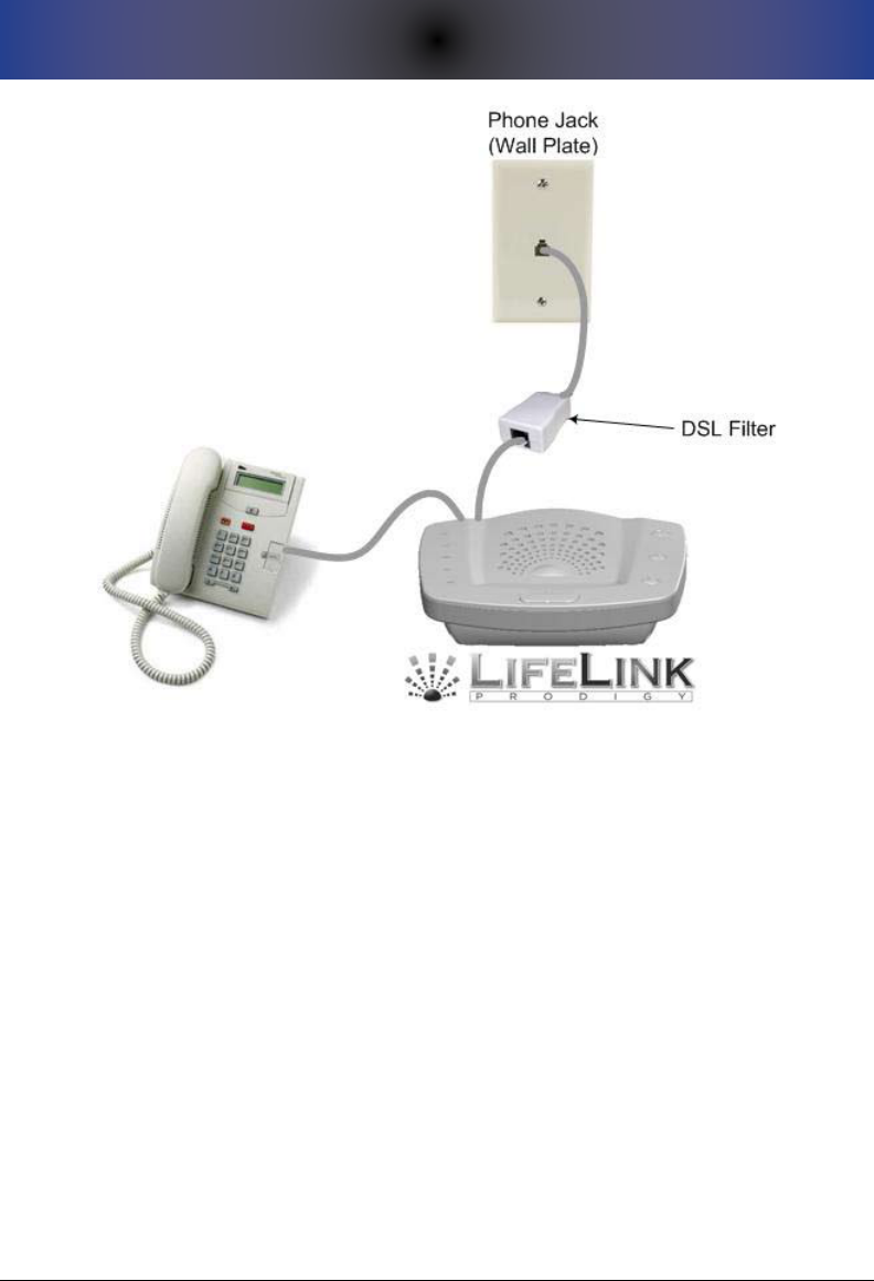
11. TROUBLESHOOTING AND TECHNICAL SUPPORT
49
In this setup, your DSL lter connects into your phone jack. Your Prodigy then
connects into the jack on the other end of the DSL lter. Optionally, you can
connect a phone into the jack on the back of your Prodigy labelled “TO PHONE”.
Prodigy Doesn’t Recognize the “0” Key
If the call recipient is pressing the “0” key and the system is not recognizing
the 0, you may need to press 0 up to 5 times to overcome potential noise or
interference on the line. Please ensure the individuals on the emergency call
list are aware of this. If you have DSL phone service at the house where Prodigy
is installed, you need a DSL lter inline between the Prodigy Console and the
telephone wall jack.
Prodigy Won’t Roll Over to the Next Number
See the section above noted as “Check Your Phone Numbers“.
For Detailed Troubleshooting Information
If you are unable to resolve your problem per the above information, please
visit www.LifelinkMedicalAlert.com/support for detailed troubleshooting

50
11. TROUBLESHOOTING AND TECHNICAL SUPPORT
information.
If your Prodigy is still not working and you cannot nd a resolution using our
online support page or forums, contact our technical support sta at 610-410-
7508 between the hours of 9:00am and 5:00pm eastern US time.

12. THE FCC WANTS YOU TO KNOW
51
12. THe fCC WanTs yoU To KnoW
This device complies with Part 15 and Part 68 of the FCC Rules. Operation is
subject to the following two conditions:
This device may not cause harmful interference, and1.
This device must accept any interference received, including 2.
interference that may cause undesired operation.
FCC Notice
This equipment has been tested and found to comply with the limits for a Class
B digital device, pursuant to Part 15 and Part 68 of the FCC Rules. These limits
are designed to provide reasonable protection against harmful interference in a
residential installation.
This equipment generates, uses, and can radiate radio frequency energy and, if
not installed and used in accordance with the instructions, may cause harmful
interference to radio communications. However, there is no guarantee that
interference will not occur in a particular installation. If this equipment does
cause harmful interference to radio or television reception, which can be
determined by turning the equipment o and on, the user is encouraged to try
to correct the interference by one or more of the following measures:
Reorient or relocate the receiving antenna.•
Increase the separation between the equipment and the receiver.•
Connect the equipment into an outlet on a circuit dierent from that to •
which the receiver is connected.
Consult the dealer or an experienced radio/TV technician for help.•
The Federal Communications Commission warns that
changes or modications of the unit not expressly approved
by the party responsible for compliance could void the user’s
authority to operate the equipment.
Radio Frequency Interference Statement
This is a Class B product. In a domestic environment, this
product may cause radio interference in which case the user
may be required to take adequate measures.
Canadian Doc Notice
This digital apparatus does not exceed the Class B limits for radio noise
emissions from digital apparatus as set out in the Radio Interference Regulation

52
12. THE FCC WANTS YOU TO KNOW
of the Canadian Department of Communications.
“Le présent appareil numérique n’èmet pas de bruits radioélectriques dépassant
les limites applicables aux appareils numériques de la class B prescrites dans
le Règlement sur le brouillage radioélectrique édicté par le ministère des
Communications du Canada.”
Ringer Equivalent Number
The Ringer Equivalent Number (REN) is used to determine the number of
devices that may be connected to a telephone line. Excessive RENs on a
telephone line may result in the devices not ringing in response to an incoming
call. In most but not all areas, the sum of the RENs should not exceed ve
(5.0). To be certain of the number of devices that may be connected to a line,
as determined by the total RENs, contact the local telephone company. Since
Prodigy has no ringer - the REN is negligible at 0.1b.

53
APPENDIX A: GLOSSARY OF TERMS
appenDIX a: glossaRy of TeRMs
The following is a list of terms which are used throughout this manual.
Glossary of TermsTable 1.
TeRM DesCRIpTIon
Automatic Test
Call
An automatic test call is a test call that is automatically initiated by your
Prodigy to execute at the time of day specified during programming.
CANCEL Button
Confirmation
Sound
Prodigy will play a sound (double-beep, the default, or a barking dog)
on the Console each time the CANCEL button is pressed either on the
Console or the Pendant. This confirmation sound has a variety of uses:
It allows a quick test of the battery in the Pendant. It also allows •
testing the wireless connection between the Pendant and the
Console.
It allows the user to determine whether or not the Pendant is •
within range of the Console.
It allows the user to hear an audible signal that conrms that they •
have successfully canceled an actual emergency call procedure.
This is often useful if they have accidentally triggered the process.
If the battery in the Pendant is low, you will hear an audible mes-•
sage on the Console stating this fact.
Optionally, if changed through Setup, a press of the CANCEL but-•
ton will play the sound of a barking dog instead of a chime. The
dog bark can be useful for those who feel that an intruder is, or
may be, lurking.
Console
Low Battery
Notification
This notification involves a telephone call to the Primary Contact to
let them know that the Console has a low or failed backup battery.
Additionally, in this situation, the CONSOLE BATTERY LED on the front
panel will flash red until the Console battery is replaced with a fresh,
working battery.
Failed Pendant
Notification
This notification involves a telephone call to the Primary Contact to let
them know that at least one Pendant at the location has either failed or
has reported a low battery. Additionally, the PENDANT STATUS LED on
the front panel will flash red until the problem is resolved.
Manual Test Call A manual test call is one that is initiated manually by the in-home user
by pressing the RUN A TEST button.
Primary Contact
The “Primary Contact” is the individual who is primarily responsible for (or
who has taken primary responsibility for) the user of the Prodigy system.
Note that it is not mandatory that you identify a Primary Contact, but
you must do so if you choose options which involve notification to the
Primary Contact. For example, if you wish to activate notification in the
event of a low battery in a Pendant, you must configure the Primary
Contact phone number first.

54
APPENDIX A: GLOSSARY OF TERMS
TeRM DesCRIpTIon
Test Required
Interval
Prodigy, by default, requires that a test call (manual or automatic) be
conducted at least once every 30 days. However, this value can be set
anywhere between 1 and 30 days. This interval of time is known as the
“Test Required Interval”.
Past versions of the LifeLink system (and similar systems on the market
today) have relied on the diligence of either the caregiver and/or the
user to test the system on a periodic basis. Failure to test is a prime
cause for a failed system during an emergency. Specifically, a non-tested
system has been found to be the biggest exposure to users of medical
alert systems. Incidentally, a secondary problem area is failure of the
user to wear their Pendant.
55
APPENDIX B: FACTORY DEFAULT SETTINGS
appenDIX b: faCToRy DefaUlT seTTIngs
The following shows the factory default settings for your Prodigy. A great
deal of thought has gone into each default setting. If you wish to change any
defaults, please give careful consideration to your decision and be sure that you
understand the implications of the change.
Factory Default SettingsTable 2.
Ca T e g o R y fUnCTIon DefaUlT seTTIng possIble ValUes
SIREN
CONTROL
Sound Siren During
Emergency? Yes Yes or No
Sound Siren During Manual
Test Call? Yes Yes or No
Sound Siren During
Automatic Test Call? No Yes or No
TEST CALLS
Automatic Test Call Function Turned off On or Off
Automatic Test Calls Go To
Individuals in
call list until 0 is
pressed
Individuals in call
list or Primary
Contact
Automatic Test Call Time
Start Time
10:00 am local
time, if activated Time of Day
Manual Test Calls Go To
Individuals in
call list until 0 is
pressed
Individuals in call
list or Primary
Contact
Test Required Interval Every 30 Days 1 to 30 Days
NOTIFICATION
Failed Pendant Notification
Call Turned off On or Off
Failed Pendant Notification
Call Start Time
1:00pm local time,
if activated Time of Day
Console Low Battery
Notification Call Turned off On or Off
Console Low Battery
Notification Call Start Time
3:00pm local time,
if activated Time of Day
Social Safety Alarm Turned off On or Off
Social Safety Time Set 9:00am local time,
if activated Time of Day
MISCELLANEOUS
Cancel Button Confirmation
Sound
Chime/Double
Beep
Chime or Barking
Dog
911 Emergency Number
(911 Equivalent Number) 911 Any phone
number

56
APPENDIX B: FACTORY DEFAULT SETTINGS
THIS PAGE INTENTIONALLY LEFT BLANK

57
APPENDIX C: DESIGN GOALS
appenDIX C: DesIgn goals
We, as a company, have spent many years analyzing our customer base and
reevaluating our legacy emergency alert systems. We have come to understand
what it is that people want and need as well as what they don’t nd value in.
Through that experience, we have engineered the Prodigy system by following
the essential design goals noted within this section.
Primary Design Goals: Form and Function
Our goal is to be • THE recognized expert in medical alert systems. Other
manufacturers want to be “all things to all people.” For example, they
develop window sensors, smoke sensors, car monitors, wander alerts,
child trackers, pet trackers, etc. most of which take away from the core
strengths of their system. They, therefore, begin to dilute their eective-
ness throughout their product line. We, by comparison, have tried to
focus on our core competency - medical alert systems. We leave the
obscure, unrelated things to those that are experts in those elds.
We understand that many individuals want to get their system up •
and running as soon as possible, while others like to take their time to
understand and consider advanced functions. In response, Prodigy
oers “simplicity out of the box” as part of a “Basic Setup” sequence of
programming steps coupled with a series of well-thought-out default
settings. For users who want to explore our optional features, they can
do that as outlined within our “Optional Features Setup” section of this
Guide.
One of the issues with medical alert systems is that the user refuses or •
simply doesn’t want to wear their Pendant. A primary reason for this
is that legacy or competitor systems are often clunky, uncomfortable,
and generally not aesthetically-appealing. Colors are often drab and
dull, and Pendants are often bulky and heavy. Your Prodigy has gone
through hundreds of hours of industrial design involving dozens of
world-class artists and designers. The goal was to produce a system
which was sleek and attractive without being extreme or overcompli-
cated-looking. We think we’ve achieved that with Prodigy – both with
our Console as well as with our Pendant designs. We think this will
result in increased utilization rates.
Past history indicates that failure to test your system could result in the •
system becoming unresponsive when you need it most. Our engineers,
acknowledging our typical customer base, have addressed virtually
every possible failure scenario. The result is a multitude of built-in
mechanisms for making sure that users -- as well as caregivers -- are
aware of a failure or imminent failure. Prodigy constantly monitors its
own health and provides visual, audible, and/or dialout notication of

58
APPENDIX C: DESIGN GOALS
the state of the system. For example, if the phone line is accidentally
disconnected from a working phone jack, a LINE STATUS indicator light
will ash red, and an audible message will play over the Console speaker
every 15 minutes indicating that there is a problem with the phone line.
As another example, if the Console is running on backup battery power,
the AC POWER indicator light will ash green and a corresponding mes-
sage will play over the speaker every 15 minutes. Optionally, the user
can congure dialout notication to the Primary Contact.
You will notice a minimal number of breakable external components. •
This helps to ensure that accidental breakage doesn’t occur that could
cause your system to malfunction unexpectedly and/or to create the
need to purchase a new unit. For example, in past models, antennas
have been broken simply by general handling of the Console. LCD
screens have been cracked/gotten wet and are often dicult to see,
particularly by the end user. In lieu of LCD functionality, the informa-
tion that was typically obtained by viewing the LCD screen is built into
the system through software; information is readily-available by the
directly-attached (or remote) telephone. Battery clips have always been
a problem; we have addressed this in our simplied design for batteries.
During setup, easy to understand voice prompts replace old-technology •
cryptic codes and/or instructions that dictate non-intuitive and strange
key sequences to be pressed in order to activate a particular function.
With Prodigy, you simply select the appropriate self-guided menu op-
tion that corresponds to the programming item you want to work with,
similar to a voice mailbox.
Primary Design Goals: Intelligence and Awareness
As noted above, in response to years of experience evaluating the shortcomings
of other medical alert systems, LifeLink engineers have spent thousands of hours
ensuring that the Prodigy design addresses each of these shortcomings. A most
notable shortcoming of other systems is the fact that, while the system operates
perfectly ne upon initial installation, things can change over time that can have
a negative aect on the operation of the system when you need it most. The
design goals dictate that no failure should occur without some sort of noti-
cation either to the end user, to an external caregiver, or both. Typical failure
scenarios that Prodigy monitors include, but are not limited to:
The phone wire (wire connecting the system to the phone wall jack) has •
become accidentally dislodged.
A Pendant has broken or has stopped working without anyone being •
notied of the problem.
The Pendant has completely failed or is low on battery power.•

59
APPENDIX C: DESIGN GOALS
The AC power wire has been accidentally dislodged from its electrical •
outlet and has caused the Console backup battery to become com-
pletely drained of power.
The Console backup battery has failed completely, rendering the system •
inoperable in the event of a power failure.
A phone has been left o-hook for an extended period.•
The end user has requested a change in phone service (for example, •
they have removed long distance service) and/or the phone company
has changed its service conguration.
AC power is out within the home, and the system has nearly (or com-•
pletely) drained the backup battery in the Console.
The system has been accidentally powered down.•
Your “Simply. Smarter.” Prodigy system performs proactive and routine health
checks to combat the potentially unrecognized failures noted above and, most
importantly, is capable of reporting on them in a variety of ways – visually,
audibly, and optionally, through outbound dialout notication. Without these
automatic checks, the responsibility would fall solely on the user. Research and
past history indicates that this is a primary area of vulnerability attributable to
age, inrmity, disability, and the like.
As you use your system, we think you will agree that we have truly engineered
the ultimate medical alert system available on the market today.

60
APPENDIX C: DESIGN GOALS
THIS PAGE INTENTIONALLY LEFT BLANK

61
APPENDIX D: SETUP MENU QUICK REFERENCE
appenDIX D: seTUp MenU QUICK RefeRenCe
The following table shows the Setup Menu structure. If you wish to use these
“Quick Key” sequences, you would simply press each numeric option allowing
approximately one second between numeric key presses if accessing subop-
tions.
Setup Menu StructureTable 3.
se T U p opTIon sUbopTIon sUbopTIon QUICK Ke y
1 - Basic Setup
1 - Pendants
1- Register a Pendant 1-1-1
2 - Delete a Pendant 1-1-2
3 - Delete all
Pendants
1-1-3
4 - Review Pendant
Registrations
1-1-4
5 - Clear Failed
Pendant Indicator
1-1-5
2 - Emergency Phone
Numbers
1 - Add an
Emergency Phone
Number
1-2-1
2 - Change an
Emergency Phone
Number
1-2-2
3 - Delete a Phone
Number
1-2-3
4 - Delete all Phone
Numbers
1-2-4
5 - Review all
Emergency Phone
Numbers
1-2-5
3 - Recorded
Message
1 - Record a Message 1-3-1
2 - Delete Recorded
Message
1-3-2
3 - Listen to Your
Recorded Message
1-3-3
2 - General
Settings
1 - Primary Contact
Phone Number
1 - Configure Primary
Contact Number
2-1-1
2 - Change Primary
Contact Number
2-1-2
3 - Delete Primary
Contact Number
2-1-3
4 - Review Primary
Contact Phone
Number
2-1-4

62
APPENDIX D: SETUP MENU QUICK REFERENCE
se T U p opTIon sUbopTIon sUbopTIon QUICK Ke y
2 - General
Settings
2 - Set or Review the
Test Required Interval
1 - Set the Test
Required Interval
2-2-1
2 - Review the
Interval
2-2-2
3 - Review Number
of Days Until Next
Test Required
2-2-3
4 - Clear the Test
Required Indicator
2-2-4
3 - System Clock
1 - Set the System
Time
2-3-1
2 - Review the
System Time
2-3-2
4 - Cancel Button
Confirmation Sound
1 - Sound a Chime 2-4-1
2 - Sound a Barking
Dog
2-4-2
5 - Override Default
911 Emergency
Number
1 - Specify 911
Equivalent Number 2-5-1
2 - Review
Emergency Number 2-5-2
3 - Recorded
Message Playback to
911 or Equivalent
2-5-3
8 - Review Firmware
Release Information
2-8
3 - Emergency Call
Options 1 - Siren Settings
1 - Allow Siren
to Sound During
Emergency
3-1-1
2 - Disallow Siren
During Emergency
3-1-2
3 - Review Siren
Settings
3-1-3
4 - Test Call Setup 1 - Automatic Test
Call Settings
1 - Turn Automatic
Test Calling On or Off
4-1-1
2 - Specify Whom to
Call During Test Call
4-1-2
3 - Siren Control
During Automatic
Test Call
4-1-3
4 - Specify Time to
Execute Test Call
4-1-4
5 - Review Automatic
Test Call Settings
4-1-5

63
APPENDIX D: SETUP MENU QUICK REFERENCE
se T U p opTIon sUbopTIon sUbopTIon QUICK Ke y
4 - Test Call Setup 2 - Manual Test Call
Settings
1 - Specify Whom to
Call During Manual
Test Call
4-2-1
2 - Siren Control
During Test Call
4-2-2
3 - Review Manual
Test Call Settings
4-2-3
5 - Notification
Settings
1 - Failed Pendant
Notification Setup
1 - Turn Failed
Pendant Notification
On or Off
5-1-1
2 - Specify Time
of Day to Execute
Notification
5-1-2
3 - Review
Notification Setup
5-1-3
4 - Clear the Pendant
Status Indicator Light
5-1-4
2 - Console Low
Battery Notification
Setup
1 - Turn Console Low
Battery Notification
On or Off
5-2-1
2 - Specify Time
of Day to Execute
Notification
5-2-2
3 - Review
Notification Settings
5-2-3
4 - Clear the Pendant
Status Indicator Light
5-2-4
3 - Social Safety
Setup
1 - Turn Social Safety
Alarm On or Off
5-3-1
2 - Specify Time of
Day to Sound the
Alarm
5-3-2
3 - Review Social
Safety Settings
5-3-3
6 - System Status
1 - Power Status 6-1
2 - Pendant Status 6-2
3 - Phone Line Status 6-3
4 - Test Required
Status
6-4
8 - Review Firmware
Version
6-8
0 - Reset to Factory
Defaults
6-0

64
APPENDIX D: SETUP MENU QUICK REFERENCE
THIS PAGE INTENTIONALLY LEFT BLANK

65
APPENDIX E: SAFETY
appenDIX e: safeTy
When using your Prodigy, please observe the following instructions in order to
reduce the risk of personal injury, electrical shock, or re. Save these instructions
for future reference.
Read all instructions carefully and make sure you understand them.
Unplug this product from the electrical outlet before attempting to 1.
clean it. Do NOT use any liquids for cleaning either the Console unit or
the Pendant. Use only a soft, slightly-damp cloth.
Do not locate the Console near any source of water, such as in the 2.
bathroom, near a sink in the kitchen, or the like.
Do not open the Console for any reason. Any attempt to open the 3.
case of the Console will void the warranty and may damage the unit or
prevent it from working properly.
Surge protection devices, both for power as well as the phone line, are 4.
recommended to protect your Prodigy in geographic areas subject
to lightning or power surges. Please consult your reseller for recom-
mended surge protection devices. Do not connect or disconnect any
telephone wires during thunderstorms.
If you are using a VoIP (Voice Over Internet Protocol) service provider 5.
such as Verizon, Time Warner, Vonage, etc., check that they do handle
emergency service calls and any conditions associated with the use of
such a service. Also, ensure that your physical address is on record and
accurately matched to your telephone number. Be sure to check that
911 service is available to you through your VoIP telephone service.
Do not use any power source other than that supplied by the manu-6.
facturer or reseller specically for this product. Use of any other power
source could damage your unit or make it unsafe.
Always dispose of batteries properly. Never throw batteries into a re. 7.
Consult your local ordinances for proper battery safety.

66
APPENDIX E: SAFETY
THIS PAGE INTENTIONALLY LEFT BLANK

67
APPENDIX F: DISCLAIMERS AND LIMITED WARRANTY
appenDIX f: DIsClaIMeRs anD lIMITeD WaR-
RanTy
Matrix Interactive, LLC warrants to the original end-user customer (“Customer”)
that each new LifeLink Prodigy Console shall be substantially free from defects in
materials and workmanship under normal use for a period of one (1) year from
the date of the original purchase (proof of purchase required). The exclusive
remedy and entire liability under this warranty will be for repair or replacement
on a like-for-like basis at Matrix Interactive’s option.
The above warranty shall not apply to product defects resulting from (a) im-
proper maintenance or installation; (b) misuse, neglect or accident; (c) damage
from moisture or corrosive environments; (d) use of the power adapter with
supply voltages other than that for which it is specied; (e) high voltage surges
over power and phone lines; (f) electrostatic discharges; (g) operation outside
the product’s specication; or (h) failure to follow product instructions.
Pendants are warranted for a period of 90 days. The AC/DC power adapter is not
warranted under any circumstances.
The warranty is void where (a) the serial number has been altered, removed
or eaced; or (b) the product has been used in an application, country, region,
locality, or connected to any network, other than those for which the product
was intended to operate, and c) the Console case/housing has been opened in
any way.
Matrix Interactive shall not have any obligation to repair or replace product
until the Customer returns defective product to Matrix Interactive or designated
agent. Any replacement product may be either new or like-new, and may con-
tain remanufactured parts, equivalent to new in performance.
EXCEPT FOR THE EXPRESS WARRANTIES SET FORTH ABOVE, AND TO THE EXTENT
PERMITTED BY APPLICABLE LAW, THE PRODUCTS ARE SUPPLIED ON AN “AS IS”
BASIS AND THERE ARE NO WARRANTIES, REPRESENTATIONS OR CONDITIONS
WHETHER EXPRESSED OR IMPLIED, WRITTEN OR ORAL, ARISING BY STATUTE,
OPERATION OF LAW, COURSE OF DEALING, USAGE OF TRADE OR OTHERWISE,
WITH RESPECT TO THE PRODUCT. MATRIX INTERACTIVE SPECIFICALLY DISCLAIMS
ANY IMPLIED WARRANTIES OR CONDITIONS OF MERCHANTABILITY, SATISFAC-
TORY QUALITY, DURABILITY, FITNESS FOR A PARTICULAR PURPOSE, AND NON-
INFRINGEMENT.
IN NO EVENT SHALL MATRIX INTERACTIVE BE LIABLE FOR ANY SPECIAL, INCIDEN-
TAL, CONSEQUENTIAL, INDIRECT OR SIMILAR DAMAGES, INCLUDING ANY LOST

68
APPENDIX F: DISCLAIMERS AND LIMITED WARRANTY
PROFITS, LOST DATA, OR OTHER INCIDENTAL OR CONSEQUENTIAL OR PUNI-
TIVE DAMAGES, WHETHER BASED ON CONTRACT, TORT (INCLUDING WITHOUT
LIMITATION, NEGLIGENCE), OR ANY OTHER LEGAL THEORY, WHETHER OR NOT
ADVISED OF THE POSSIBILITY OF SUCH DAMAGES, OR WHETHER SUCH DAM-
AGES ARE FORESEEABLE, IN ANY EVENT, THE TOTAL AGGREGATE LIABILITY OF
MATRIX INTERACTIVE FOR DIRECT DAMAGES SHALL NOT EXCEED THE PURCHASE
PRICE OF THE PRODUCT.
COMMUNICATION AND RESPONSE LIMITATIONS: Purchaser acknowledges that
signals which are transmitted over telephone lines, or other modes of com-
munication, pass through communication networks wholly beyond the control
of Matrix Interactive and are not maintained by Matrix Interactive. Therefore,
Matrix Interactive shall not be responsible for any equipment or communica-
tion failure which prevents transmission signals from reaching your contact list
including emergency 911 operators or damages arising as a result. Purchaser
acknowledges that Matrix Interactive provides no response to its Prodigy equip-
ment. The equipment is designed to communicate with the contact list of your
choice as well as emergency 911 operators. Matrix Interactive is not and shall
not be responsible for ambulance, police or other emergency response time or
that any response will be provided by the anyone on your contact list including
the emergency 911 response center.
ELECTRIC AND TELEPHONE SERVICE IS NECESSARY AND PURCHASER’S RESPON-
SIBILITY: Purchaser acknowledges that the Prodigy equipment plugs into a
standard landline telephone jack and communicates over standard telephone
lines using two way voice communication. VoIP Internet will not work when
your electricity service is interrupted unless you have battery backup for the de-
vice or devices providing the service. Purchaser acknowledges that the Prodigy
equipment requires 110 Volt AC (USA and Canada model) power and electrical
outlets and receptacles, telephone hook-ups, RJ11 block or equivalent, all of
which is Purchaser’s responsibility to obtain and maintain.
TESTING AND SERVICE OF PRODIGY EQUIPMENT: Your Prodigy equipment, once
installed, is in the exclusive possession and control of the Purchaser, and it is
Purchaser’s sole responsibility to test the operation of equipment and request
warranty service if the equipment is under warranty.
PURCHASER’S EXCLUSIVE REMEDY: Purchaser’s exclusive remedy for Matrix Inter-
active’s default hereunder is to require Matrix Interactive to repair or replace, at
Matrix Interactive’s option, any equipment or part of the emergency alert system
which is non-operational during Matrix Interactive’s warranty period.

69
APPENDIX G: TECHNICAL SPECIFICATIONS
appenDIX g: TeCHnICal speCIfICaTIons
The following are the technical specications for your LifeLink Prodigy.
aTTRIbUTe speCIfICaTIon
PHONE JACKS 1 RJ11 2-Pin Modular LINE Jack
1 RJ11 2-Pin Modular PHONE Jack
MAXIMUMS
Max Pendants: 12
Max Phone Numbers: 8
Max Digits Per Phone Number: 20
Max Recorded Message Length: 20 Seconds
BATTERIES 9-Volt Console Backup Battery; Backup Time ~ 20 hours
3-Volt CR2032 (Lithium) Pendant Battery
POWER Input: 100-240 VAC 50-60Hz 190mA
Output: 12V DC, 500mA
WIRELESS
Frequency: 916 MhZ/FSK for North America
868 MhZ/FSK Outside of North America
Range: 500 feet in open air
DIMENSIONS
Console Size: 10mm (L) 15mm (W) 12mm (H)
Console Weight: 22 Ounces
Pendant Size: 10mm (L) 10mm (W) 5mm (H)
Pendant Weight: .5 Ounces
OPERATING
TEMPERATURE
Minimum is 20° F (-7° C)
Maximum is 100° F (38° C)
STORAGE
TEMPERATURE
Minimum is 15° F (-9° C)
Maximum is 120° F (49° C)