MaxStream 24XSTREAM 24XSTREAM User Manual 1
MaxStream Inc. 24XSTREAM 1
UserManual.wiki
>
MaxStream
>
24XSTREAM User Manual
users manual
Navigation menu
Upload a User Manual
Namespaces
Wiki Guide
HTML
PDF
Info
Views
User Manual
Discussion / Help
Navigation


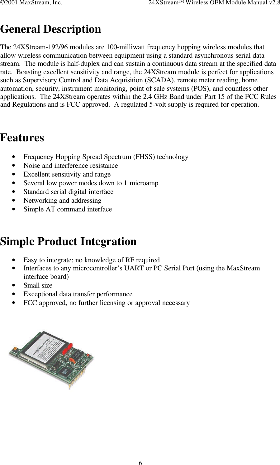
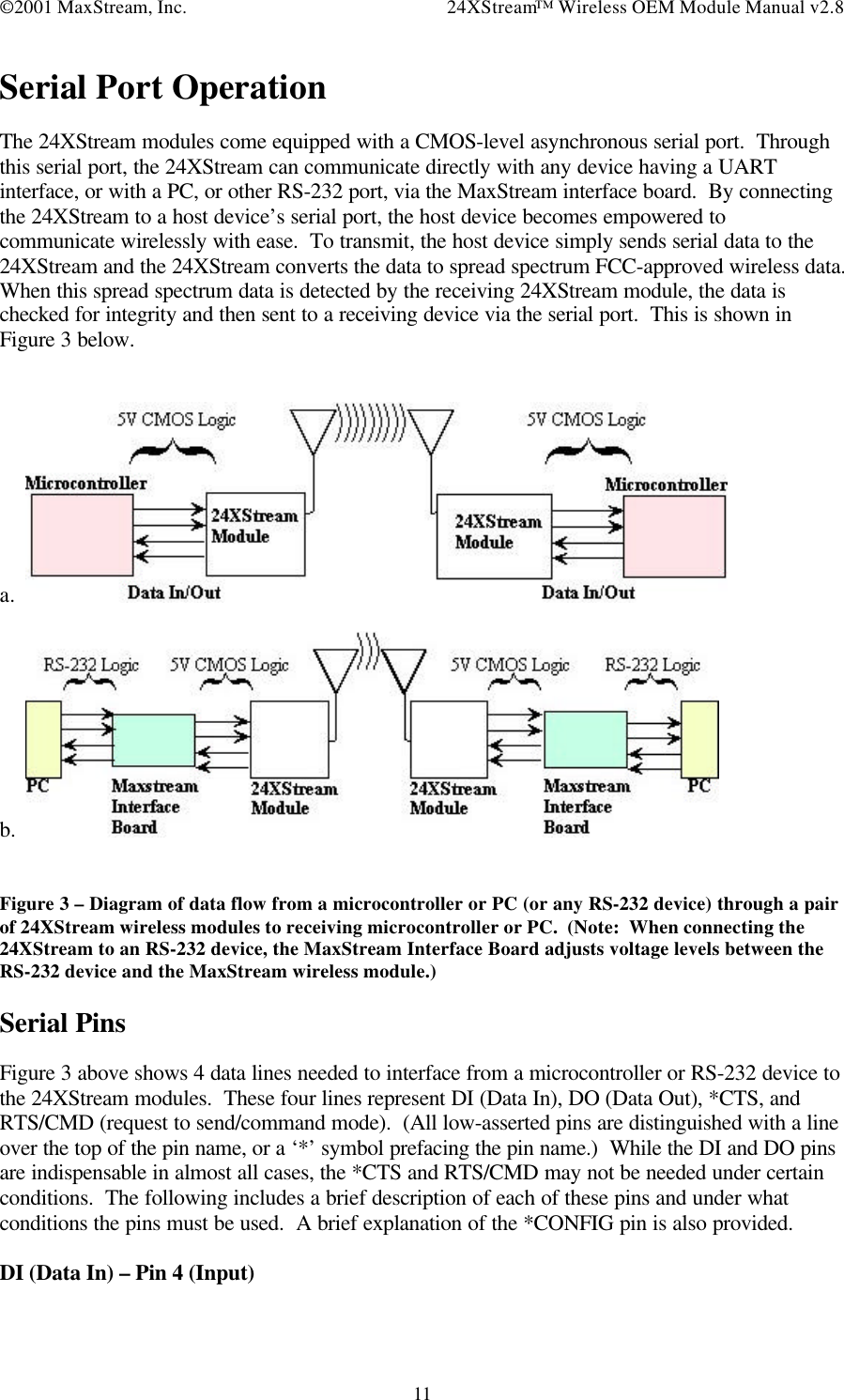
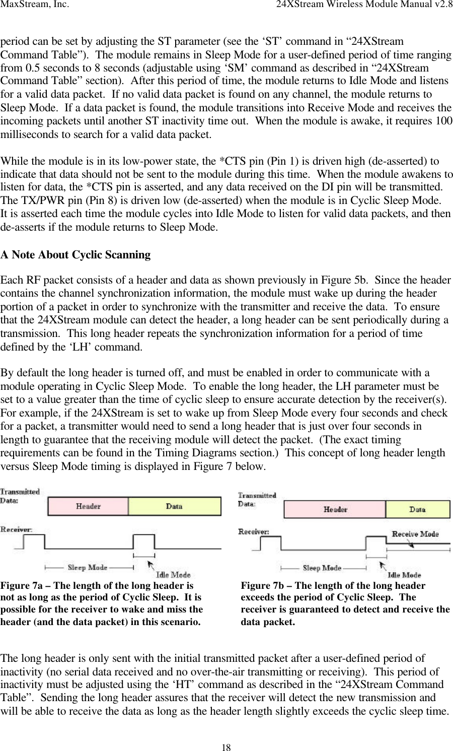
![©2001 MaxStream, Inc. 24XStream™ Wireless OEM Module Manual v2.87Block DiagramFigure 1 – Block diagram demonstrating basic module operation and data flow for both transmit andreceive.DiagramThe 24XStream data module connectsto a host device using an 11 pin headerand a 4 pin header (0.1” spaced).[TOP VIEW]Figure 2 – Top view diagram of the 24XStreammodule with pin layout and dimensions.2.8250](https://usermanual.wiki/MaxStream/24XSTREAM/User-Guide-224594-Page-7.png)