MaxStream 9XCITE 900 MHZ Wireless OEM Module User Manual MaxStream Wireless Modem Networking
MaxStream Inc. 900 MHZ Wireless OEM Module MaxStream Wireless Modem Networking
UserManual.wiki
>
MaxStream
>
9XCITE User Manual
users manual
Navigation menu
Upload a User Manual
Namespaces
Wiki Guide
HTML
PDF
Info
Views
User Manual
Discussion / Help
Navigation
![9XCite Wireless OEM Module – Product Manual v1.0 9XCite Wireless OEM Module Powerfully Simple The 9XCite Module is a drop-in wireless solution that adds connectivity to any UART or serial device. It transfers a standard asynchronous serial data stream and features the following: • Continuous data stream of up to 38400 bps (factory-set, over-the-air baud rate) • Serial Interfacing from 1200 to 57600 bps • Software selectable between Hopping (FHSS) and Single Channel modes • Approved by the FCC under Part 15 of the FCC Rules and Regulations • Variable input supply voltage (2.85 – 5.50 VDC) This manual contains information critical to basic 9XCite Module operation. More detailed information is available in the “XCite Advanced Programming & Configuration” Manual. (Located on the MaxStream CD or on the web: www.maxstream.net/support_documentation.html) Features: FCC Approved (USA) [Go to Appendix A for FCC Requirements] Devices that embed 9XCite Modules inherit MaxStream’s FCC certification. IC (Industry Canada) Certified ISM (Industrial, Scientific & Medical) frequency band MaxStream products manufactured under ISO 9002 registered standards since 2000. Indoor/Urban Range: Up to 300’ (90 m) Outdoor/LOS Range: Up to 1000’ (300 m) w/dipole antenna Receiver Sensitivity: -108 dBm (9600 Baud), -104 dBm (38400 Baud) Transmit Power Output: 1 mW [50 mW effective considering excellent receiver sensitivity] Advanced Networking capabilities (True Peer-to-Peer (no “master” required), Point-to-Point, Point-to-Multipoint, Multi-Drop) Specifications [Appendix B] 1-Year Warranty [Appendix C] Free Technical Support [Appendix D] © 2003 MaxStream, Inc., Confidential and Proprietary 1](https://usermanual.wiki/MaxStream/9XCITE/User-Guide-382672-Page-4.png)
![9XCite Wireless OEM Module – Product Manual v1.0 Block Diagram Figure 1. 9XCite Module Block Diagram InterferenceFilterRF TX Buffer TransmittingCircuitryRF RX Buffer ReceivingCircuitryRF SwitchDIN BufferAntennaPortDINDOUTGNDVCCCTSDOUT Buffer ‘Interference Filter’ reduces interference from pagers and cellular. Module Pinout Signals 9XCite Module pin signals and their functions: Table 1. J1 Pin Descriptions (Low-asserted signals distinguished with a horizontal line over signal name.) Module Pin Signal Name I/O When Active Description 1 O* low Clear-to-Send Flow Control 2 SLEEP (PWRDN) I* high Can be used to enter Sleep Mode 3 DO (Data Out) O* n/a Serial Data leaving the 9XCite Module (to the processor host) 4 DI (Data In) I n/a Serial Data entering the 9XCite Module (from the processor host) 5 I** low Request-to-Send 6 I* low Reset module 7 RX LED O high Receive LED low - Asserted during transmission 8 / PWR O high PWR – Indicates power is on 9 CONFIG I*** low Backup method for entering Command Mode. Primary method is with “+++” [See CC Parameter] 10 VCC I - 2.85 – 5.50 VDC variable 11 GND - - Ground * Pin utilizes 10K Ω Pull-Up resistor (Already installed in the module) ** Pin utilizes 10K Ω Pull-Down resistor (Already installed in the module) *** Pin utilizes 100K Ω Pull-Up resistor (Already installed in the module) For More InformationGo to the "XCite Advanced Programming & Configuration" Manual for more detailed information about module signal pinouts.The advanced manual is available on the MaxStream CDor on the web: www.MaxStream.net Note When integrating the 9XCite Module onto a Host PC Board, all lines that are not used should be left disconnected (floating). Table 2. J2 Pin Descriptions Module Pin Pin Name 1 reserved 2 GND 3 GND 4 GND J2 Pins are used primarily for mechanical stability and may be left disconnected. © 2003 MaxStream, Inc., Confidential and Proprietary 2](https://usermanual.wiki/MaxStream/9XCITE/User-Guide-382672-Page-5.png)
![9XCite Wireless OEM Module – Product Manual v1.0 Pinout Signal Overview The interface signals are available through the 11-pin header. All pins operate on VCC CMOS levels. Five signals that are commonly used in applications are: • DI (pin 4 – Data In) • DO (pin 3 – Data Out) • VCC (pin 10 – Power) • GND (pin 11 – Ground) • (pin 1 – Clear-to-Send) The remaining 6 pins (SLEEP (PWRDN), , , RX LED, /PWR, ) may be used for additional functionality. Go to the “XCite Advanced Programming & Configuration Manual” for more detailed information about module pinouts. Application Circuit Figure 2. Application Circuit – connection to host processor Serial Data Data enters the 9XCite Module through the DI Pin as an asynchronous serial signal. The signal should idle high when no data is being transmitted. Each data packet consists of a start bit (low), 8 data bits (least significant bit first) and a stop bit (high). The following figure illustrates the serial bit pattern of data passing through the module. Figure 3. UART data packet 0x1F (decimal number “31”) as transmitted through the 9XCite Module The 9XCite Modules transfer 7 or 8 bits over-the-air [Selectable using BI Parameter]. The start and stop bits from the UART signal are not transmitted, but are regenerated on the receiving module. DI (Data In) Buffer Once serial data has entered the 9XCite Module through the Data In (DI) Pin, the data is stored in the DI Buffer until it can be transmitted. Once the first byte of data enters the DI Buffer, the module begins to initialize the RF channel (unless RF data is being received). In the case where the module is receiving RF data, the serial data is stored in the DI Buffer. When the DI Buffer has only 17 bytes of memory left, the 9XCite Module de-asserts (high) to signal to the host device to stop sending data. re-asserts once the DI Buffer has at least 35 bytes available in memory. Once in the DI Buffer, the data is packetized for transmission. [The packet structure is broken down on the next page.] © 2003 MaxStream, Inc., Confidential and Proprietary 3](https://usermanual.wiki/MaxStream/9XCITE/User-Guide-382672-Page-6.png)
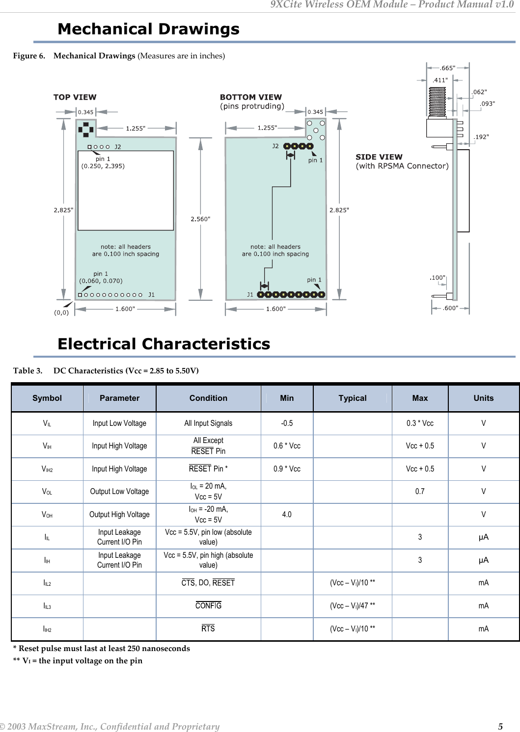
![9XCite Wireless OEM Module – Product Manual v1.0 <VID><ATHP><ATDT><PSN><Pay Load><CRC> <VID> Factory assigned Vendor ID number <ATHP> Channel (or Network) number <ATDT> Module Address <PSN> Packet Serial Number (8-bit number that uniquely identifies each packet) <Pay Load> Data shifted into module for transmission <CRC> 16-bit CRC (like a checksum) for error detection Timing Specifications The diagram below [Figure 4] shows 9XCite Modules providing an RF Link between hosts. Figure 4. System Block Diagram DI (data in)DO (data out)CTSRTS / CMDHOST A XCiteModule AXCiteModule BDI (data in)DO (data out)CTSRTS / CMDHOST B The RF data flow sequence is initiated when the first byte of data is received by the transmitting 9XCite Module. As long as 9XCite Module A is not already receiving data, the serial data goes into the DI Buffer, is packetized and then transmitted to 9XCite Module B. Figure 5. Timing Specifications (“A” and “B” are associated with figure 4) A Transmits over airB ReceivesTSTTTXTTLTRLHost A sends serial data to XStream Module AAfter 1st byte is received, contents of D Buffer are assembled into packet and transmittedINTX/PWR LED on XStream Module A pulses off briefly to indicate RF transmissionIf 16-bit CRC checks out, data is shifted out serial port to Host B(Optional) Set ATCS = 1 to use CTS as RS-485 TX enable low-asserted signalRXLED pulses on briefly to indicated RF receiveactivityD AINRF AOUTTXLED AD BOUTRXLED BCTS B © 2003 MaxStream, Inc., Confidential and Proprietary 4](https://usermanual.wiki/MaxStream/9XCITE/User-Guide-382672-Page-7.png)
![9XCite Wireless OEM Module – Product Manual v1.0 RF System Components Serial Communications The 9XCite Wireless OEM Module interfaces to a host device through a CMOS-level asynchronous serial port. Through its serial port, the 9XCite Module can communicate directly with any UART-interfaced or RS-232/485/422 device. [Timing specifications illustrated on page 4] UART-Interfaced Data Flow Devices that have a UART interface can connect directly through the pins of the 9XCite Wireless OEM Module as is shown in the figure below. Figure 7. Data Flow in a UART-interfaced environment (Low-asserted signals distinguished with horizontal line over signal name.) DI (data in)DO (data out)CTSRTSMicrocontrollerCMOS Logic CMOS LogicMicrocontrollerXCiteModuleXCiteModuleDI (data in)DO (data out)CTSRTS RS-232 and RS-485/422 Data Flow Wiring the 9XCite Module to a host device serial port enables the host device to communicate wirelessly. To transmit, the host device simply sends serial data to the 9XCite Module pins. The 9XCite Module then converts the data to Frequency Hopping Spread Spectrum (FHSS) or Single Channel FCC-approved wireless data. Once transmitted, the over-the-air data can be detected by receiving 9XCite Modules, checked for integrity and then sent to a receiving device [Figure below]. Figure 8. Data Flow in RS-232 and RS-485/422 environments. (Low-asserted signals distinguished with a horizontal line over signal name.) CMOS LogicTXRS-232 Logic CMOS Logic RS-232 LogicXCiteModuleRTSCTSRXMaxStreamInterfaceBoardPC PCDO (data out)RTSDI (data in)CTSMaxStreamInterfaceBoardTXRTSCTSRXDO (data out)RTSDI (data in)CTSXCiteModule© 2003 MaxStream, Inc., Confidential and Proprietary 6](https://usermanual.wiki/MaxStream/9XCITE/User-Guide-382672-Page-9.png)
![9XCite Wireless OEM Module – Product Manual v1.0 MaxStream Interface Board Components & Features 9a. Power Switch Move the Power Switch to the on (up) position to power the Interface Board. DIP Switch [10a] settings are only read during a power-up sequence. 9b. LEDs The LED indicators visualize diagnostic status information. The radio modem’s status is represented as follows: Yellow (top LED) = Serial Data Out Green (middle) = Serial Data In Red (bottom) = Power/TX Indicator (Red light is on when powered, off briefly during RF transmission) 9c. DB—9 Connector Standard female DB-9 (RS-232) DCE connector – This connector can be also used for RS-485 and RS-422 connections. 9d. Power Connector 7-18 VDC Power Connector (Center positive, 5.5/2.1mm) – Power can also be supplied through Pin 9 of the DB-9 Connector. 10a. DIP Switch The DIP Switch configures the 9XCite OEM Module to operate in different modes. DIP Switch settings are only read and applied during a powering-on sequence. [See Figure 11 below for DIP Switch settings] 10b. Configuration Switch The Configuration Switch provides an alternate way to enter “AT Command Mode”. To enter “AT Command Mode” at the radio modem’s default baud rate, hold the Configuration Switch down while powering on the module using the Power Switch. Figure 11. MaxStream Interface Board DIP Switch Settings * The “Restore Defaults” setting, for switches 1 & 2, can be used to restore AT Settable parameters to their default states. Once switches are in position, reset occurs during next power- up © 2003 MaxStream, Inc., Confidential and Proprietary 8](https://usermanual.wiki/MaxStream/9XCITE/User-Guide-382672-Page-11.png)
![9XCite Wireless OEM Module – Product Manual v1.0 Module Configuration The following versions of the 9XCite Module are currently available: • 900 MHz, 9600 (over-the-air) Baud, Hopping Channel Mode • 900 MHz, 9600 Baud, Single Channel mode • 900 MHz, 38400 Baud, Hopping Channel mode • 900 MHz, 38400 Baud, Single Channel mode 9XCite Modules can operate in both Single Channel and Hopping modes. Mode is selectable using the “Function Set” dropdown list of the “XCite Configuration” tab of the MaxStream-provided XCite-CTU Software. For More InformationGo to the "XCite Advanced Programming & Configuration"Manual for more detailed information about module configurations.The advanced manual is available on the MaxStream CDor on the web: www.MaxStream.net)The 9XCite Module is shipped with a unique parameter set in its memory. Parameters within the set are organized under the following three categories: AT Commands, Non-AT Settable Parameters and Read-Only AT Commands. Command & Parameter Types AT Commands AT Commands can be changed at any time by entering AT Command Mode and sending commands to the module. AT Commands can be modified using the any of the following means: • XCite-CTU Software • Serial Communications Software (“HyperTerminal”, “Pro Comm”, etc.) • Microcontroller Non-AT Settable Parameters (XCite-CTU Software configurable only) Non-AT Settable Parameters can only be adjusted using the MaxStream-provided XCite-CTU Software. To modify Non-AT Settable Parameter, connect the module to the serial com port of a PC (interface board is necessary for RS-232 connection) and modify parameter values through the XCite-CTU Software interface. These parameters enable features that need to be set before the module is used in the field. [Non-AT Settable Parameters are listed in table 7.] Non-AT Settable Parameters can be modified using the following means: • XCite-CTU Software (MaxStream-provided) © 2003 MaxStream, Inc., Confidential and Proprietary 9](https://usermanual.wiki/MaxStream/9XCITE/User-Guide-382672-Page-12.png)
![9XCite Wireless OEM Module – Product Manual v1.0 Configuration Software XCite-CTU Software XCite-CTU is MaxStream-provided software used to configure 9XCite Modules. It is the only means that can be used to set all three command parameter types [AT Commands, Non-AT Settable Parameters & Read-Only AT Commands]. For More InformationGo to the Interfacing Softwaresection of the "XCite Advanced Programming & Configuration" manual for step-by-stepinstruction on how to accomplish XCite-CTU functions.The advanced manual is available on the MaxStream CDor on the web: www.MaxStream.netXCite-CTU Software is organized into 3 tabs: • PC Settings tab - Setup PC serial ports to interface with an XCite Module assembly • Range Test tab – Test an 9XCite Module's range and monitor packets sent and received • XCite Configuration tab – Configure and read parameters of 9XCite Modules Figure 12. XCite-CTU User Interface (PC Settings, Range Test & XCite Configuration tabs) Install XCite-CTU software Double-click the "setup_XCite-CTU.exe" file and follow prompts of the installation screens. (The "setup_XCite-CTU.exe" file is located in the MaxStream CD “Software” folder and also on the web: http://www.maxstream.net/products_software.html) Using XCite-CTU software In order to use the XCite-CTU software, a module assembly (a 9XCite Module mounted to a MaxStream Interface Board) must be connected to the serial port of a PC. The baud rate of the serial port (“Setup” tab) must match the baud rate of the module (BD (Baud Rate) Command on the “Configuration” tab). Serial Communications Software (for AT Commands Only) Serial Communications Software can be used to issue AT and Read-Only AT Commands, but cannot be used to set Non-AT Settable Parameters. “HyperTerminal” and “Pro Comm” are examples of commonly used serial communications software. “HyperTerminal” comes installed with Windows XP, 2000 and NT. All AT Commands are sent as follows: AT + [2 Character ASCII Command] + [Optional Space] + [Parameter (HEX)] + [CR] (CR = Carriage return) © 2003 MaxStream, Inc., Confidential and Proprietary 12](https://usermanual.wiki/MaxStream/9XCITE/User-Guide-382672-Page-15.png)
![9XCite Wireless OEM Module – Product Manual v1.0 9XCite (900 MHz) Approved Antenna List ANTENNA WARNING WARNING This device has been tested with Reverse Polarity SMA connectors with the antennas listed in Table A1 [next page]. When integrated into the OEM product, these fixed antennas require installation preventing end-users from replacing them with non-approved antennas. Any antenna not already tested with the 9XCite module must be tested to comply with FCC Section 15.203 for unique antenna connectors and Section 15.247 for emissions. Table A1. Antennas approved for use with the 9XCite Wireless OEM Module. Part Number Type Gain Application * Yagi 6.2dBi Fixed/Mobile * Yagi 7.2dBi Fixed/Mobile A09-Y8 Yagi 8.2dBi Fixed/Mobile Yagi 9.2dBi Fixed/Mobile Yagi 10.2dBi Fixed/Mobile A09-Y11 Yagi 11.2dBi Fixed/Mobile Yagi 12.2dBi Fixed/Mobile Yagi 13.2dBi Fixed/Mobile Yagi 14.2dBi Fixed/Mobile A09-Y15 Yagi 15.2dBi Fixed/Mobile A09-F2 Omni Direct. 2.2dBi Fixed A09-F5 Omni Direct. 5.2dBi Fixed A09-F8 Omni Direct. 8.2dBi Fixed * Omni Direct. 9.2dBi Fixed * Omni Direct. 7.2dBi Fixed A09-M7 Omni Direct. 7.2dBi Fixed A09-H 1/2 wave antenna 2.1dBi Fixed/Mobile A09-HBMM-P5I 1/2 wave antenna 2.1dBi Fixed/Mobile A09-QBMM-P5I 1/4 wave antenna 1.9 dBi Fixed/Mobile * 1/4 wave integrated wire antenna 1.9 dBi Fixed/Mobile * FCC-approved antennas not inventoried by MaxStream – Contact MaxStream for more information. In addition to the antennas listed in Table A1, over 100 additional antennas have been tested and approved for use with the 9XCite module. Contact MaxStream toll-free (1-866-765-9885) for a complete list that includes “Mag Mount”, “Dome”, “Multi-path” and “Panel” antennas. RF EXPOSURE WARNING The antenna(s) used for this transmitter must be installed to provide a separation distance of at least 20 cm from all persons and must not be co-located or operating in conjunction with any other antenna or transmitter for satisfying RF exposure compliance. The preceding statement must be included as a CAUTION statement in manuals for OEM products to alert users on FCC RF Exposure compliance. © 2003 MaxStream, Inc., Confidential and Proprietary 15](https://usermanual.wiki/MaxStream/9XCITE/User-Guide-382672-Page-18.png)

![9XCite Wireless OEM Module – Product Manual v1.0 © 2003 MaxStream, Inc., Confidential and Proprietary 19 Appendix D: Troubleshooting & FAQs Contact MaxStream MaxStream technical support prides itself on timely and thorough solution-delivery. MaxStream technical support engineers are versed in RF and EE technologies and are readily accessible via the means listed below. By contacting MaxStream technical support, you benefit from many years of combined field experience. Several on-line support features are available. Please use the following resources for additional support: FAQs http://www.maxstream.net/support_faq.html Documentation http://www.maxstream.net/support_documentation.html Technical Support Live Chat: www.MaxStream.net Phone: (801) 765-9885 eMail: support@MaxStream.net MaxStream office hours are 8:00am – 5:00pm [U.S. Mountain time zone]](https://usermanual.wiki/MaxStream/9XCITE/User-Guide-382672-Page-22.png)