MaxStream 9XSTREAM 9XSTREAM Wireless OEM Module User Manual
MaxStream Inc. 9XSTREAM Wireless OEM Module
User Manual

MaxStream 9XStream™ Wireless OEM Module Manual v2.8
1 Confidential and Proprietary, ©MaxStream, Inc. 2001
9XStream™
Wireless OEM Module
Operation Manual v 2.8

MaxStream 9XStream™ Wireless OEM Module Manual v2.8
2 Confidential and Proprietary, ©MaxStream, Inc. 2001
Table of Contents
FCC Compliance...............................................................................4
FCC Qualifications ...........................................................................4
Warranty ...........................................................................................6
Overview ............................................................................................7
Features............................................................................................................8
Simple Product Integration............................................................................8
Serial Port Operation .......................................................................9
Serial Pins ........................................................................................................9
DI (Data In) – Pin 4 (Input) .....................................................................10
DO (Data Out) – Pin 3 (Output) ..............................................................11
CTS – Pin 1 (Output)................................................................................11
RTS/CMD – Pin 5 (Input) ........................................................................12
CONFIG – Pin 9 (Input)...........................................................................12
Modes of Operation ........................................................................13
Idle Mode .......................................................................................................13
Transmit Mode..............................................................................................13
Data Validity..............................................................................................15
Transmission Latency...............................................................................15
Receive Mode.................................................................................................16
Sleep Mode.....................................................................................................17
Pin Sleep (SM=1)......................................................................................17
Serial Port Sleep (SM=2).........................................................................17
Cyclic Sleep (SM=3-7) .............................................................................18
Cyclic Scanning ......................................................................................18
Command Mode..............................................................................19
AT Commands ..............................................................................................20
Exiting AT Command Mode....................................................................21
Binary Commands ........................................................................................21
Networking and Addressing ..........................................................23
Vendor Identification Number (VID) .........................................................23
Networks ........................................................................................................24
Module Address ............................................................................................24
Module Address Mask..................................................................................24

MaxStream 9XStream™ Wireless OEM Module Manual v2.8
3 Confidential and Proprietary, ©MaxStream, Inc. 2001
Glossary ...........................................................................................26
Application Notes............................................................................30
Appendix A – Packaging Information ........................................................34
Appendix B – J1/J2 Pin Descriptions..........................................................35
Appendix C – Specifications ........................................................................36
Appendix D – Product Listing .....................................................................37
Appendix E – 9XStream Commands ..........................................................39
Appendix F – Timing Diagrams ..................................................................42
Appendix G – Electrical Characteristics ....................................................43
Appendix H – Sleep Mode Settings .............................................................48
Appendix I – Module Part Numbers...........................................................49
Using the 9XStream Development Kit..........................................51
Introduction: .................................................................................................51
Contents:........................................................................................................51
Instructions:...................................................................................................52
Index.................................................................................................55
MaxStream 9XStream™ Wireless OEM Module Manual v2.8
4 Confidential and Proprietary, ©MaxStream, Inc. 2001
FCC Compliance
FCC NOTICE
LABELING REQUIREMENTS
ANTENNA WARNING
WARNING: This device complies with Part 15 of the FCC Rules. Operation is subject to the
following two conditions: (1) this device may not cause harmful interference and (2)
this device must accept any interference received, including interference that may
cause undesired operation.
WARNING: This device has been tested with Reverse Polarity SMA and MMCX connectors with
the antennas listed below. When integrated in the OEMs product, these fixed
antennas require installation preventing end-users from replacing them with non-
approved antennas. Any antenna not in the following table must be tested to compl
y
with FCC Section 15.203 for unique antenna connectors and Section 15.247 for
emissions.
WARNING: The Original Equipment Manufacturer (OEM) must ensure that FCC labeling
requirements are met. This includes a clearly visible label on the outside of the
OEM enclosure specifying "Contai
as well as the FCC Notice above.
ns Transmitter Module, FCC ID: OUR9XSTREAM

MaxStream 9XStream™ Wireless OEM Module Manual v2.8
5 Confidential and Proprietary, ©MaxStream, Inc. 2001
FCC Qualifications
IMPORTANT: The 9XSTREAM module has been certified by the FCC
for integration into OEM products without any further
certification (as per FCC section 2.1091.) Changes or
modifications not expressly approved by MaxStream
could void the user’s authority to operate the equipment.
In order to fulfill the certification requirements, however, the OEM must comply
with FCC regulations:
1. The system integrator must ensure that the external label provided with
this device is placed on the outside of the final product.
2. The 9XStream may be used only with Approved Antennas that have
been tested with this module.
Approved Antenna List
Manufacturer Part Number Type Gain Application
Connector
Type
Minimum
Separation
Distance
MaxStream A09-Y6 Yagi 6.2dBi Fixed/Mobile RPSMAF 20cm
MaxStream A09-Y7 Yagi 7.2dBi Fixed/Mobile RPSMAF 20cm
MaxStream A09-Y8 Yagi 8.2dBi Fixed/Mobile RPSMAF 20cm
MaxStream A09-Y9 Yagi 9.2dBi Fixed/Mobile RPSMAF 20cm
MaxStream A09-Y10 Yagi 10.2dBi Fixed/Mobile RPSMAF 20cm
MaxStream A09-Y11 Yagi 11.2dBi Fixed/Mobile RPSMAF 20cm
MaxStream A09-Y12 Yagi 12.2dBi Fixed/Mobile RPSMAF 20cm
MaxStream A09-Y13 Yagi 13.2dBi Fixed/Mobile RPSMAF 20cm
MaxStream A09-Y14 Yagi 14.2dBi Fixed/Mobile RPSMAF 20cm
MaxStream A09-Y15 Yagi 15.2dBi Fixed/Mobile RPSMAF 20cm
MaxStream A09-F2 Base Station 2.2dBi Fixed RPSMAF 20cm
MaxStream A09-F5 Base Station 5.2dBi Fixed RPSMAF 20cm
MaxStream A09-F8 Base Station 8.2dBi Fixed RPSMAF 20cm
MaxStream A09-F9 Base Station 9.2dBi Fixed RPSMAF 20cm
MaxStream A09-W7 Base Station 7.2dBi Fixed RPSMAF 20cm
MaxStream A09-M7 Base Station 7.2dBi Fixed RPSMAF 20cm
MaxStream A09-H 1/2 wave antenna 2.1dBi Fixed/Mobile RPSMAF 20cm
MaxStream
A09-HBMM-
P6I 1/2 wave antenna 2.1dBi Mobile MMCX 20cm
MaxStream
A09-QBMM-
P6I 1/4 wave antenna 1.9 dBi Mobile MMCX 20cm
MaxStream A09-QI
1/4 wave integrated
wire antenna 1.9 dBi Mobile Integrated 20cm

MaxStream 9XStream™ Wireless OEM Module Manual v2.8
6 Confidential and Proprietary, ©MaxStream, Inc. 2001
RF EXPOSURE
Warranty
The 9XStream module from MaxStream (the "Product") is warranted against defects in
materials and manufacturing under normal use in accordance with instructions and
specifications published by MaxStream in connection with its Development Kits or as
otherwise published by MaxStream from time to time, for a period of 90 days from the date
of purchase from MaxStream. In the event of a product failure due to materials or
workmanship, MaxStream will repair or replace the defective product. For warranty
service, return the defective product to MaxStream, shipping prepaid, for prompt repair or
replacement.
The foregoing sets forth the full extent of MaxStream's warranties regarding the Product.
Repair or replacement at MaxStream's option is the exclusive remedy. THIS WARRANTY
IS GIVEN IN LIEU OF ALL OTHER WARRANTIES, EXPRESS OR IMPLIED, AND
MAXSTREAM SPECIFICALLY DISCLAIMS ALL WARRANTIES OF
MERCHANTABILITY OR FITNESS FOR A PARTICULAR PURPOSE. IN NO EVENT
SHALL MAXSTREAM, ITS SUPPLIERS OR LICENSORS BE LIABLE FOR
DAMAGES IN EXCESS OF THE PURCHASE PRICE OF THE PRODUCT, FOR ANY
LOSS OF USE, LOSS OF TIME, INCONVENIENCE, COMMERCIAL LOSS, LOST
PROFITS OR SAVINGS, OR OTHER INCIDENTAL, SPECIAL OR
CONSEQUENTIAL DAMAGES ARISING OUT OF THE USE OR INABILITY TO USE
THE PRODUCT, TO THE FULL EXTENT SUCH MAY BE DISCLAIMED BY LAW.
SOME STATES DO NOT ALLOW THE EXCLUSION OR LIMITATION OF
INCIDENTAL OR CONSEQUENTIAL DAMAGES. THEREFOR, THE FOREGOING
EXCLUSIONS MAY NOT APPLY IN ALL CASES. This warranty provides specific legal
rights. Other rights which vary from state to state may also apply.
WARNING: This equipment is approved for mobile / base station applications
When using the 9Xstream with mobile or base station antennas, a minimum
separation distances of 20 centimeters or more must be maintained. To ensure
compliance, operation at distances closer than this is not recommended.
The preceding statement must be included as a CAUTION statement in
manuals for OEM products to alert users on FCC RF Exposure compliance.
MaxStream 9XStream™ Wireless OEM Module Manual v2.8
7 Confidential and Proprietary, ©MaxStream, Inc. 2001
Overview
The 9XStream 12, 96, and 192 modules are 100-milliwatt, frequency-hopping
wireless modules that allow wireless communication between equipment using
a standard asynchronous serial data stream. The half-duplex transmission of
the 9XStream can sustain a continuous data stream at the specified data rate.
The 9XStream has been engineered for use with the following applications
(among others):
• Supervisory Control and Data Acquisition (SCADA)
• Remote meter reading
• Home Automation
• Security
• Instrument monitoring
• Point of Sale Systems (POS)
The 9XStream operates within the 900 MHz ISM Band and is approved by the
FCC under Part 15 of FCC Rules and Regulations. A regulated 5-volt supply
is required for operation.
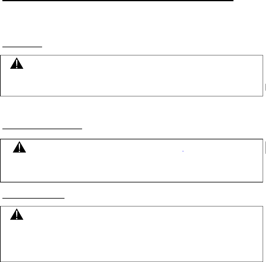
Figure 1a - Block diagram demonstrating basic module
operation and data flow for both transmit and receive.

MaxStream 9XStream™ Wireless OEM Module Manual v2.8
8 Confidential and Proprietary, ©MaxStream, Inc. 2001
Features
• Frequency-Hopping Spread Spectrum (FHSS) technology
• Noise and interference resistance
• Enhanced sensitivity and range
• Multiple Low-power modes (down to 1 Microamp)
• Standard serial digital interface connection
• Built-in Networking and addressing
• Simple AT command interface
Simple Product Integration
The 9XStream doesn’t require previous knowledge of RF operation. It
interfaces to any UART or PC Serial Port using the MaxStream interface
board and has been developed with a small form-factor for ease of integration.
The data transfer performance of the 9XStream has been enhanced with
proprietary technology from MaxStream and requires no additional licensing
or FCC approval.
MaxStream 9XStream™ Wireless OEM Module Manual v2.8
9 Confidential and Proprietary, ©MaxStream, Inc. 2001
Serial Port Operation
The 9XStream modules come equipped with a CMOS-level asynchronous
serial port, which provides direct communication with any device having a
UART interface (Universal Asynchronous Receiver-Transmitter). The serial
port can also communicate with a COM port on a personal computer, or other
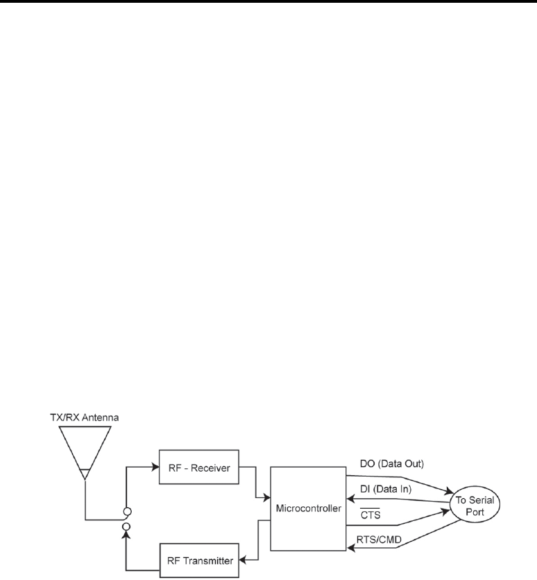
RS-232 port via the MaxStream interface board. By connecting the 9XStream
to the serial port on a host device, the host becomes a wireless communication
device. To transmit, the host device simply sends data from its serial port to
the 9XStream and the 9XStream converts the data into spread spectrum, FCC-
approved wireless data. The data is then detected by a receiving 9XStream
module, checked for integrity, and sent to a receiving device via the serial port
(Figure 2a).
Serial Pins
Figure 2a above shows 4 data lines needed to interface from a microcontroller
or RS-232 device to the 9XStream modules. These four lines represent DI
(Data In), DO (Data Out), CTS, and RTS/CMD (request to send/command
mode). (All low-asserted pins are distinguished with a line over the top of the
pin name, or a ‘*’ symbol prefacing the pin name.) While the DI and DO pins
are indispensable in almost all cases, the CTS and RTS/CMD may not be
needed under certain conditions. The following includes a brief description of
each of these pins and under what conditions the pins must be used. A brief
explanation of the CONFIG pin is also provided.
MaxStream 9XStream™ Wireless OEM Module Manual v2.8
10 Confidential and Proprietary, ©MaxStream, Inc. 2001
DI (Data In) – Pin 4 (Input)
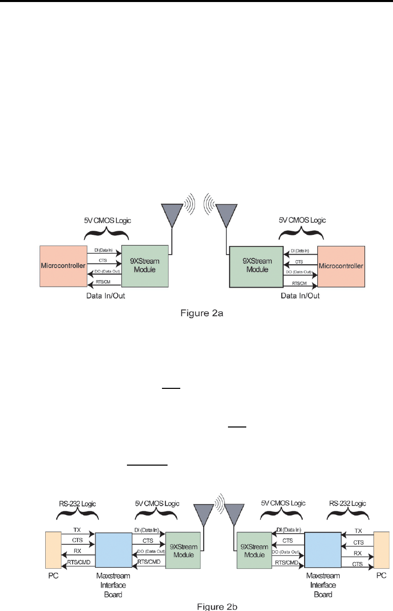
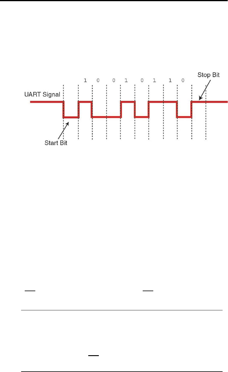
Data enters the 9XStream on the DI pin as an asynchronous serial signal. The
serial signal is idle (high) when no data is being transmitted. Each data packet
consists of a start bit (low), 8 data bits, and a stop bit (high) as shown below in
Figure 3.
Figure 3
The 9XStream modules transfer exactly 8-bits over the air. The start and stop
bits from the UART signal are not actually transmitted, but are regenerated on
the receiving module before they are sent out the serial port. This allows for
the following data configurations to be sent:
• 8-bit, no parity, 1 stop bit
• 7-bit, even parity, 1 stop bit
• 7-bit, odd parity, 1 stop bit
• 7-bit, no parity, 2 stop bits
Since the 9XStream is half-duplex, it can only transmit or receive at a given
time. Thus, once the first byte is detected on the DI pin, the 9XStream
immediately begins transmitting the incoming data unless over-the-air data is
already being received. In this case, the data on the DI pin is stored in the data
buffer until data is no longer being received at the antenna. If the 9XStream
receives a lengthy sequence of serial data (while receiving over-the-air
data), the data buffer could reach its capacity (132 bytes) in which case the
CTS signal will need to be implemented (see CTS section below).
Note: The 9600 and 19200-baud modules allow incoming serial data
to be transferred at a rate of 2400-57600 bits/second. Serial
data can be transferred to the module at a rate equal to or
less than the module’s over-the-air baud rate without any
problems. However, if the serial interface rate is set to
exceed the module’s baud rate (9600 or 19200 bps
respectively), CTS must be implemented since the data
buffer may become full.

MaxStream 9XStream™ Wireless OEM Module Manual v2.8
11 Confidential and Proprietary, ©MaxStream, Inc. 2001
DO (Data Out) – Pin 3 (Output)
Data received from over-the-air transmissions is checked for errors and then
sent to the DO pin.
CTS – Pin 1 (Output)
The CTS pin (clear to send) informs the host device whether or not serial data
can be sent to the 9XStream module. When CTS registers as low, serial data
can be sent to the 9XStream module. All incoming serial data is stored in a
data buffer until the next data packet is transmitted (over-the-air). The data
buffer can hold up to 132 bytes of data. At 115 bytes, the 9XStream module
de-asserts the CTS signal (sets it high) to alert the host device to stop sending
serial data. The CTS remains de-asserted until the number of bytes in the
buffer drops below 98.
There are three cases in which the data buffer may become full:
1. When the 9600 and 19200-baud modules are configured at a higher serial
data rate than the module’s over-the-air baud rate causing the data buffer
to become momentarily full and CTS to de-assert.
2. The 9XStream module is a half-duplex transmitter/receiver. If the module
is receiving a long, continuous string of over-the-air data, any serial data
that arrives at the buffer will not be transmitted until the module no longer
detects over-the-air data.
3. If any module in a network (see Networking and Addressing) is
transmitting data, all other modules in the network will not transmit until
they finish receiving data. If the network modules receive lengthy serial
data, their data buffers may become full.
Note: In applications where none of these conditions occur, the
CTS signal need not be monitored.

MaxStream 9XStream™ Wireless OEM Module Manual v2.8
12 Confidential and Proprietary, ©MaxStream, Inc. 2001
RTS/CMD – Pin 5 (Input)
RTS The RTS signal (request to send) is not implemented for flow control
with the 9XStream modules. All received data (over-the-air) is sent out the
serial port regardless of the RTS signal.
CMD The 9XStream comes with a variety of configurable settings including
power-saving modes and network addressing options. This pin may be used
as a way to manually configure the 9XStream module. When this pin is
asserted (high), incoming serial data (on the DI pin) is interpreted as
commands instead of data. (See the Command Mode section of this manual.)
CONFIG – Pin 9 (Input)
The CONFIG pin (low-asserted) is used to force the module to enter AT
Command Mode. When asserted (low), the serial port baud rate is temporarily
set to match the default baud rate of the 9XStream module. This ensures that
the module will transition into AT Command Mode at a known baud rate.
Upon entering AT Command Mode, all configured parameters, including the
baud rate, remain in their saved state and can be modified as described in the
AT Command Mode section.
IMPORTANT:DO NOT tie the CONFIG pin to an external device as it
may cause problems with module operation. The
CONFIG pin should be tied to an external switch and
used manually to enter AT Command Mode only when
the AT Command Mode cannot be entered under the
normal procedure (see the
AT Command Mode
section).
MaxStream 9XStream™ Wireless OEM Module Manual v2.8
13 Confidential and Proprietary, ©MaxStream, Inc. 2001
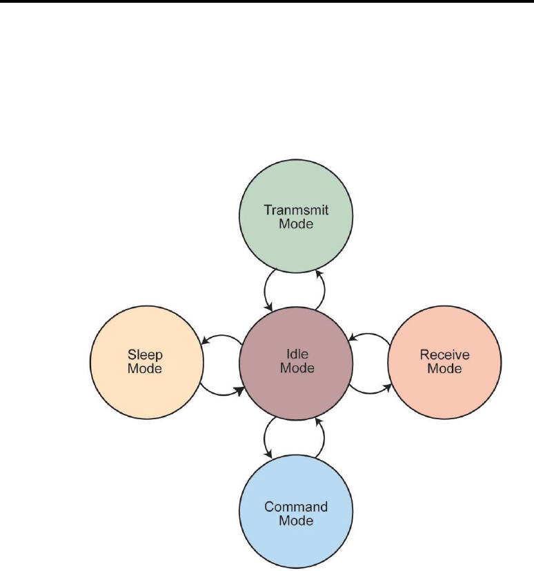
Modes of Operation
The 9XStream wireless module features several modes of operation that allow
the module to be responsive to data and yet utilize minimum power. The
figure below shows these modes, followed by a comprehensive look into each
and the necessary conditions for the 9XStream module to transition from one
mode to another.
Figure 4
Idle Mode
The 9XStream module operates in Idle Mode when there is no data being
transmitted or received. The module transitions to Transmit Mode once data
is presented on the DI pin. If valid data is detected at the antenna, the module
will switch from Idle Mode to Receive Mode. When no longer transmitting
or receiving, the module returns to Idle Mode.
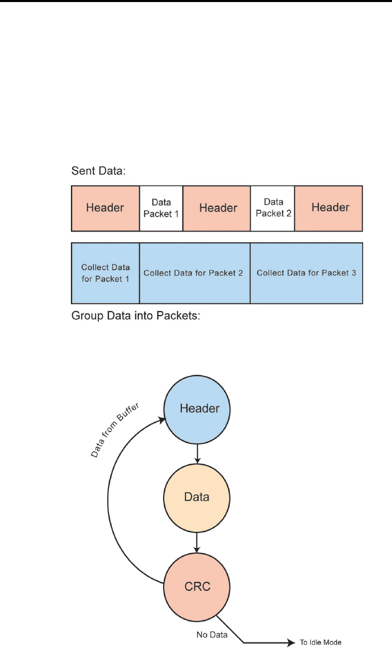
Transmit Mode
When the first byte arrives in the data buffer through the DI pin, the module
leaves Idle Mode and transitions to Transmit Mode. This transition happens
instantaneously from the moment the first byte of data arrives in the data
buffer. In Transmit Mode, a header is sent out and is followed by the first
data packet, which has a CRC (Cyclic Redundancy Check) attached (see the
MaxStream 9XStream™ Wireless OEM Module Manual v2.8
14 Confidential and Proprietary, ©MaxStream, Inc. 2001
Transmit Mode (cont.)
Data Validity section for more information). The first data packet contains
all bytes that accumulated in the data buffer while the header was being sent.
After the first data packet is sent, another header will be sent if data is
available in the buffer. The header is followed by another data packet. The
second data packet (and all subsequent data packets) will consist of data that
accumulated in the buffer while the previous data packet and header were
being sent (see Figure 5a). The size of each data packet can vary up to 64
bytes. This progression is shown in Figure 5b.
Figure 5a – Generation of data packets
Figure 5b – Transmit Mode description

MaxStream 9XStream™ Wireless OEM Module Manual v2.8
15 Confidential and Proprietary, ©MaxStream, Inc. 2001
Data Validity
To verify data integrity, a 16-bit cyclic redundancy check (CRC) is
computed for the transmitted data and attached to the end of each data packet
before transmission. The receiver will then compute the CRC on all
incoming data. Any received data that has an invalid CRC is discarded.
Transmission Latency
The length of time required to send a packet of data depends on the number
of bytes being sent and the baud rate. In addition, modules have a
Synchronization Timer option that can be manually configured using the SY
command as discussed in the 9XStream Commands Table (Appendix E).
Modifying this parameter can significantly change the transmission latency.
See the Timing Diagrams section for more information on transmission
latencies.
Note: As outlined in Figure 5a, a header always prefaces a data
packet. The header contains information that is used by all
receivers (within range) to synchronize their hopping
patterns to the transmitter. The length of the header can be
reduced in some applications by eliminating the
synchronization information. See
Timing Diagrams
for more
information.
MaxStream 9XStream™ Wireless OEM Module Manual v2.8
16 Confidential and Proprietary, ©MaxStream, Inc. 2001
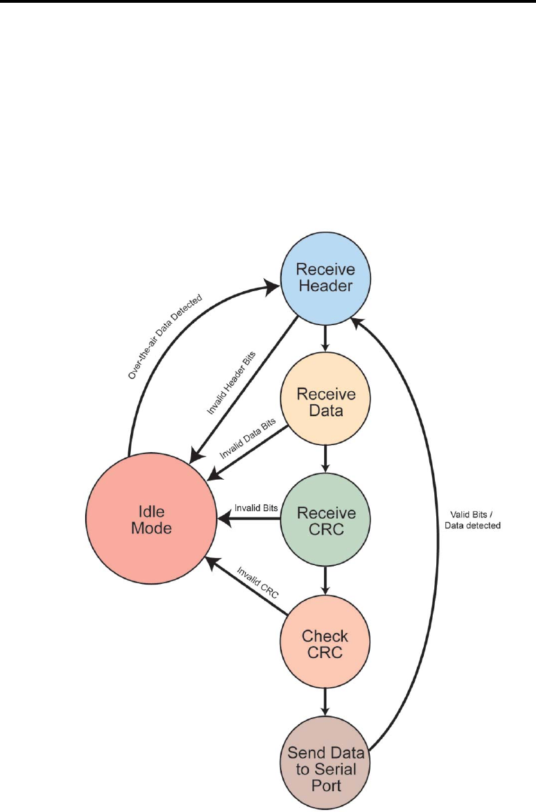
Receive Mode
If over-the-air data is present at the RF receiver when the module is in Idle
Mode, it will transition to Receive Mode and start receiving packets. Once a
packet is received, it goes through a CRC (cyclic redundancy check) to
ensure that the data was transmitted correctly. If the CRC data bits on the
incoming packet are invalid, the packet is discarded. If the CRC is valid, the
packet is sent to the serial port via the DO pin. This process is shown in
Figure 6 below.
Figure 6 – Receive Mode description

MaxStream 9XStream™ Wireless OEM Module Manual v2.8
17 Confidential and Proprietary, ©MaxStream, Inc. 2001
Receive Mode (cont.)
The module will remain in Receive Mode until an error is detected in the
received data, or data is no longer transmitted, at which point, the module
transitions to Idle Mode. If serial data was stored in the data buffer while the
module was in Receive Mode, the data will be transmitted after the module
returns to Idle Mode.
Sleep Mode
Sleep Mode enables the 9XStream module to go into a low-power state in
which minimal power is consumed when the module is not in use. Once in
Sleep Mode, the module will not transmit or receive data until it first returns
to Idle Mode. To enter Sleep Mode, the module must be inactive (no data
transmission or reception) for a user-defined period of time (specified by the
ST command). After this time elapses, the module transitions to Sleep
Mode. By default, Sleep Mode is disabled and must be enabled using the
SM command.
The 9XStream features several Sleep Mode settings, each of which makes
use of different mechanisms to enter or leave Sleep Mode. The table in
Appendix H lists the various Sleep Mode settings and the requirements to
transition to and from Sleep Mode for each setting.
Pin Sleep (SM=1)
After enabling the Pin Sleep setting, the Sleep pin (Pin 2) controls whether
the 9XStream is active or in Sleep Mode. If Sleep is de-asserted, the module
is fully operational. Once Sleep is asserted, the module transitions to Sleep
Mode and remains in its lowest power consuming state until the Sleep pin is
de-asserted. The 9XStream requires 85 ms to transition from Sleep Mode to
Idle Mode. The Sleep pin is only active if the module is set up to operate in
this mode; otherwise the pin is ignored. (See the SM command in the
9XStream Commands Table (Appendix E), for more information.) Once
in Pin Sleep Mode, the CTS pin (Pin 1) is de-asserted (high) to indicate that
data should not be sent to the module during this time. The TX/PWR pin
(Pin 8) is also de-asserted (low) when the module is in Pin Sleep Mode.
Serial Port Sleep (SM=2)
If this state is enabled, the module goes into Sleep Mode after a user-defined
period of inactivity (no transmitting or receiving of data). This period of
time can be changed by modifying the ST command. When the module is in
Serial Port Sleep Mode, the TX/PWR pin (Pin 8) is de-asserted (low). The
module will return to Idle Mode once a character is received on the DI pin.

MaxStream 9XStream™ Wireless OEM Module Manual v2.8
18 Confidential and Proprietary, ©MaxStream, Inc. 2001
Cyclic Sleep (SM=3-7)
If the Cyclic Sleep setting is enabled, the 9XStream module goes into Sleep
Mode after a user-defined period of inactivity (no transmission or reception on
the RF channel). The user-defined period may be set by adjusting the ST
parameter (see the ST command in the 9XStream Commands Table –
Appendix E).
The module remains in Sleep Mode for a user-defined period of time ranging
from 0.5 seconds to 8 seconds (adjustable using SM command). After this
period of time, the module returns to Idle Mode and listens for a valid data
packet. If no valid data packet is found (on any channel), the module returns to
Sleep Mode. If a data packet is found, the module transitions into Receive
Mode and receives the incoming packets until another ST inactivity time out
occurs. When the module is awake, it requires 100 milliseconds to search for a
valid data packet.
While the module is in a low-power state, the CTS pin (Pin 1) is de-asserted
(high) to indicate that data should not be sent to the module during this time.
When the module awakens to listen for data, the CTS pin is asserted, and any
data received on the DI pin will be transmitted. The TX/PWR pin (Pin 8) is also
de-asserted (low) when the module is in Cyclic Sleep Mode. It is asserted each
time the module cycles into Idle Mode to listen for valid data packets, and then
de-asserts if the module returns to Sleep Mode.
Cyclic Scanning
Each RF packet consists of a header and data as shown previously in Figure 5a.
Since the header contains the channel synchronization information, the module
must wake up during the header portion of a packet in order to synchronize with
the transmitter and receive the data. To ensure that the 9XStream module can
detect the header, a long header can be sent periodically during a transmission.
This long header repeats the synchronization information for a period of time
defined by the LH command.
By default, the long header is turned off and must be enabled in order to
communicate with a module operating in Cyclic Sleep Mode. To enable the
long header, the LH parameter must be set to a value greater than the time of
cyclic sleep to ensure accurate detection by the receiver(s). For example, if the
9XStream is set to wake up from Sleep Mode every four seconds and check for
a packet, a transmitter would need to send a long header that is just over four
seconds in length to guarantee that the receiving module will detect the packet.
(Exact timing requirements can be found in the Timing Diagrams section.)
This concept of long header length versus Sleep Mode timing is displayed in
Figure 7a and b.

MaxStream 9XStream™ Wireless OEM Module Manual v2.8
19 Confidential and Proprietary, ©MaxStream, Inc. 2001
Figure 7a – The length of
the long header is not as
long as the period of
Cyclic Sleep. It is possible
for the receiver to wake
and miss the header (and
the data packet) in this
scenario.
Figure 7b – The length of the
long header exceeds the
period of Cyclic Sleep. The
receiver is guaranteed to
detect and receive the data
packet.
The long header is only sent with the initial transmitted packet after a user-
defined period of inactivity (no serial data received and no over-the-air
transmitting or receiving). This period of inactivity must be adjusted using the
HT command as described in the 9XStream Commands Table (Appendix E).
Sending a long header assures that the receiver will detect the new transmission
and will be able to receive the data (as long as the header length slightly exceeds
the cyclic sleep time).
Command Mode
Command Mode allows several features, including the power-down and
addressing options, to be configured. These adjustable parameters offer greater
flexibility to designers in configuring the module to fit specific design criteria.
There are three ways to enter Command Mode:
1. Assert RTS/CMD and send a binary command.
2. Send the sequence “+++” to send AT commands.
3. Assert (low) the CONFIG pin and turn the power switch off and back on.
Important: Do not tie CONFIG pin to microprocessor. (See the
Serial Port Operation
section for more information.)
Once in Command Mode, the configurable parameters can be adjusted using
either AT commands or Binary commands, as explained below. Any parameters
that are changed while in Command Mode must be saved to non-volatile
memory using the WR command, or they will reset to their stored value upon
reset or power-up.

MaxStream 9XStream™ Wireless OEM Module Manual v2.8
20 Confidential and Proprietary, ©MaxStream, Inc. 2001
Command Mode (cont.)
In these examples, sent or received ASCII characters are marked in
quotations. Quotation marks should not be included when sending
commands to the 9XStream modules. Carriage Returns (ASCII character
13) will be denoted as <CR>. Binary values are represented in this
document with < and >. These characters are also not sent as part of the
actual command. All binary values are represented as hexadecimal values
(HEX) in these examples, and are denoted by an H after the number. The
actual Binary Command values must all be sent in binary with the Least
Significant Byte (LSB) sent first followed by the Most Significant Byte
(MSB) if the value is larger than one byte.
AT Commands
The following sections contain a description of the AT and Binary Command
Modes along with some examples. In these examples, sent or received ASCII
characters are marked in quotations.
AT commands can be sent to the module using ASCII commands and
parameters. A special break sequence is used so that the module will transition
into AT Command Mode. The default sequence for entering AT Command
Mode is as follows:
• No characters sent for one (1) second.
(Time modified by BT command.)
• Three (3) plus characters (+++) sent within one (1) second.
(Character modified by CC command.)
• No characters sent for one (1) second.
(Time modified by AT command.)
The 9XStream module responds by sending an OK<CR>.
All AT commands are sent as follows:
AT
+
Two (2)
Character
ASCII
Command
+
Optional
Space
+
Parameter
(HEX)
+
Carriage
Return
The ASCII command consists of AT followed by two alphanumeric bytes, and
the parameter is a number represented as ASCII hexadecimal characters (0-9, A-
F). The ASCII commands and parameters are not case-sensitive. The optional
space can be any non-alpha-numeric character
After executing a recognized AT command, the module responds with an
OK<CR>. If an unrecognized command or a command with a bad parameter is
received, the module will respond with an ERROR<CR>.

MaxStream 9XStream™ Wireless OEM Module Manual v2.8
21 Confidential and Proprietary, ©MaxStream, Inc. 2001
AT Commands (cont.)
A modified AT value is reset upon module power-down unless the WR
command is issued to save the parameter to non-volatile memory.
To query the current value of a particular command, send the corresponding AT
command without any parameters (carriage return, however, is still sent). The
response will be the current value of that command reported as a hexadecimal
number.
The following example demonstrates basic AT Command functionality in the
9XStream module.
Example: This example will change the user-defined Module
Address to 1A0D (HEX) and check the current value of
the SM command. It will also write the new Module
Address to non-volatile memory.
SEND
RESPONSE
+++ OK<CR>
ATDT 1A0D<CR> OK<CR>
ATSM<CR> 0 <CR>
ATWR<CR>
(write to non-volatile memory)
OK<CR>
ATCN<CR>
(exit AT Command Mode)
OK<CR>
Exiting AT Command Mode
There are two ways to exit the AT command mode and return to Idle Mode. If no
valid AT commands are received within the time specified by the AT Command
Timeout parameter (CT command), the module will return to Idle Mode
automatically. Alternatively, the AT command mode can be exited by sending
the CN command.
Binary Commands
Binary command bytes are organized as follows:
<Command><Parameters>
1 byte
2 bytes
When sending a Binary command to the 9XStream, the Command byte must be
sent while the RTS/CMD pin (Pin 5) is asserted. RTS/CMD can be de-asserted
100 microseconds after the stop bit from the Command byte has been sent. It
does not matter whether RTS/CMD is asserted when the Parameter bytes are
sent. The command will execute when all the parameters associated with the
command have been sent. If all parameters aren’t received within 0.5 seconds
the module will return to Idle Mode.

MaxStream 9XStream™ Wireless OEM Module Manual v2.8
22 Confidential and Proprietary, ©MaxStream, Inc. 2001
Binary Commands (cont.)
Note: When parameters are sent, they are always two bytes long with
the Least Significant Byte sent first. When they are read, they
are 1 or 2 bytes long as indicated in the
9XStream Command
Table
(Appendix E).
Binary Command Mode allows multiple commands to be sent in sequence.
When the RTS/CMD pin is asserted, all incoming serial data will be interpreted
as commands. Commands can be sent in sequences of commands and their
associated parameters. If RTS/CMD remains asserted, all received commands
will be executed by the 9XStream module. All modified parameters must be
stored in non-volatile memory by sending the WR command (08H with no
parameters) before powering down or resetting the module or the changes will be
lost.
Commands can be queried for their current value by sending the command
logically ORed with the value 80H (hexadecimal) with RTS/CMD asserted.
When this binary value is sent (with no parameters) the current value of the
command will be sent back, through the DO pin.
Note: For the 9XStream module to recognize a Binary command, the
RT command must be issued from AT Command Mode to enable
binary programming. If binary programming is not enabled,
the module will not recognize when the RTS/CMD pin is
asserted and will therefore not recognize Binary Commands.
Example: This example will set Sleep Mode to the Pin Sleep setting
and store the new Sleep Mode value to non-volatile memory.
(Again, the RT command must be issued in AT Command
Mode to enable binary programming before Binary Command
Mode will work.)
Assert RTS/CMD (Enter command mode.)
Send bytes: (Send SM1 command)
<01H> (Command Byte - SM)
<01H> (Least significant bit of the
Parameter Bytes - 01H)
<00H> (Most significant bit of the
Parameter Bytes – 00H)
Send bytes: (Send WR command)
<08H> (Command Byte - WR)
De-assert RTS/CMD
MaxStream 9XStream™ Wireless OEM Module Manual v2.8
23 Confidential and Proprietary, ©MaxStream, Inc. 2001
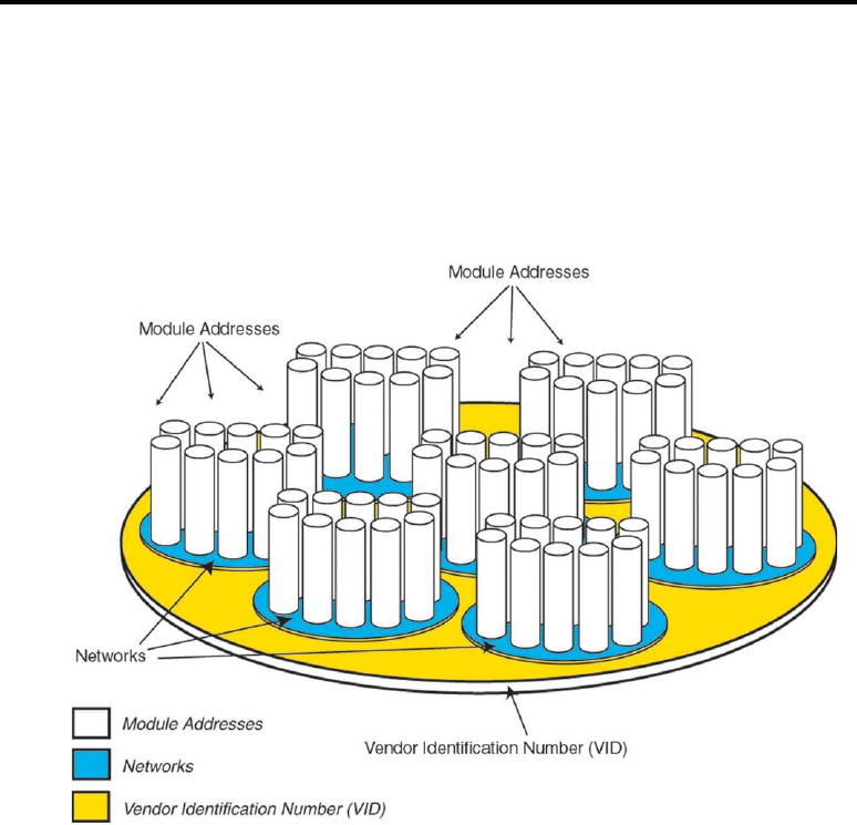
Networking and Addressing
The 9XStream modules utilize three levels of addressing to communicate
between modules. This networking hierarchy is depicted in Figure 8 below.
Only modules with the matching addresses are able to communicate. The three
methods of addressing are: Vendor Identification number, Networks, and
Module Addresses.
Figure 8 – Layout of a typical network configuration. The 9XStream
features a powerful set of networking and addressing options allowing the
functionality of complex networking systems.
Vendor Identification Number (VID)
For network security, a unique Vendor Identification Number (VID) can be
requested. The VID is programmed into the 9XStream module at the factory and
is stored in permanent memory. This number can only be changed at the factory.
Only modules with matching VID numbers can communicate together. VID
addressing ensures that modules with a given VID are immune to either
transmissions or receptions with 9XStream modules of a different VID in the
same vicinity. To request a unique VID number, contact MaxStream to obtain a
VID Request Form.

MaxStream 9XStream™ Wireless OEM Module Manual v2.8
24 Confidential and Proprietary, ©MaxStream, Inc. 2001
Networks
Within each VID, there are seven available networks. Each network utilizes a
different pseudo-random hopping sequence to navigate through the shared
hopping channels. In the event that two modules from different networks collide
on a channel (because they hop in a different sequence) the two modules will
jump to separate channels on the next hop. Using networks, multiple module
pairs can operate in the same vicinity with minimal interference from each other.
The network parameter is user-definable using the HP command as described in
the 9XStream Command Table (Appendix E).
Module Address
Module Addresses and Module Address Masks provide another level of
addressing among 9XStream modules. Each module in a network can be
configured with a 16-bit Module Address to establish selective communications
within a network. This address is set to one of 65535 values using the “DT”
command. The default Module Address is 0000H.
All modules with the same Module Address can transmit and receive data among
themselves. Any modules on a network with different Module Addresses will
still detect and listen to the data in order to maintain network synchronization.
However, they will not send the data out to their serial ports if their Module
Addresses don’t match the Module Address of the transmitter. (The Module
Address Mask can be used to provide exceptions to this rule as described in the
following section.)
Module Address Mask
The Module Address Mask can be used as an additional method to facilitate
communication among modules. The Module Address Mask can also be set to
one of 65535 possible values using the MK command. The default value is
FFFFH.
All transmitted data packets contain the Module Address of the transmitting
module. When a transmitted packet is received by a module, the Transmitter
Module Address (contained in the packet) is logically “ANDed” (bitwise) with
the Receiver Module Address Mask. If the resulting value matches the
Receiver Module Address, or if it matches the Receiver Module Address Mask,
the packet is accepted. Otherwise, the packet is discarded.
Note: When performing this comparison, any “0” values in the
Receiver Module Address Mask are treated as
Irrelevant
values
and are ignored.
MaxStream 9XStream™ Wireless OEM Module Manual v2.8
25 Confidential and Proprietary, ©MaxStream, Inc. 2001
Module Address Mask (cont.)
Packets with a Transmitter Module Address of FFFFH are received by all
modules (as shown below in Figure 9). A Transmitter Module Address that
matches the Module Address Mask is called a Global Address.
Figure 9 – Demonstration of Module Address comparison at
receiver. FFFFH logically “ANDed” with any Module
Address Mask will equal the Module Address Mask.
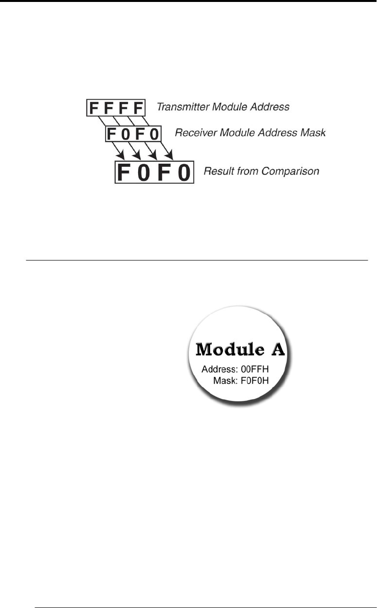
Example: Consider Module A with Module Address of 00FFH and
Module Address Mask F0F0H (Figure 10).
Figure 10
Module A can receive packets from other modules in
three ways:
1. From modules with a Transmitter Module Address of
00FFH.
2. By logically “ANDing” a F0F0H Mask with the Receiver
Module Address to receive
0XFX
(HEX).
3. From an address that matches the Module Address
Mask of the module (F0F0H), or packets from a module
having a Transmitter Module Address (Global Address)
of
FXFX
(since the two
0
values in FOFOH are
insignificant
).

MaxStream 9XStream™ Wireless OEM Module Manual v2.8
26 Confidential and Proprietary, ©MaxStream, Inc. 2001
Glossary
AT commands – A set of commands that can be used to customize and
configure the 9XStream module to meet specific needs. AT commands are sent
via a serial communications program such as HyperTerminal.
Binary commands – A set of commands used to configure the 9XStream
module. Binary commands are sent with RTS/CMD asserted. The RT command
must be used to enable binary programming prior to using binary commands.
Multiple Binary commands can be issued sequentially while RTS/CMD is
asserted.
Clear to send – See CTS pin.
CMOS logic – Logic levels used by the 9XStream module (0-5V).
Command Mode – A mode of operation, which manually modifies the
configurable parameters of the 9XStream module. Both Binary and AT
command modes are available.
Command table – Table containing 23 currently implemented commands. This
table lists all of the adjustable parameters along with a brief description of each.
CRC – See Cyclic Redundancy Check.
CTS pin – The low-asserted Clear To Send pin (Pin 1) provides flow control
for the 9XStream module. When CTS is asserted (low), serial data can be sent to
the module for transmission. If the module is unable to transmit the data, CTS
may de-assert (high) once the data buffer nears capacity to prevent buffer
overflow.
Cyclic redundancy check (CRC) – Used by the 9XStream module to ensure
data integrity during transmission. A CRC is computed on the bits to be
transmitted over-the-air and sent with each data packet. The CRC is recomputed
by the receiver and compared with the original CRC bits. The packet is valid if
the receiver CRC matches the CRC computed by the transmitter.
Cyclic sleep – Sleep Mode setting in which the module enters a low-power state
and awakens periodically to determine if any transmissions are being sent.
Data buffer – Collects incoming serial data prior to over-the-air data
transmission. The data buffer can hold up to 132 bytes at a given time. When
the buffer fills to 115 bytes, the Clear To Send (CTS) pin is de-asserted to stop
the flow of incoming serial data.
Data packets – A grouping of data to be sent over-the-air. Each data packet
contains a header and data that is collected from the data buffer. The size of the
packets varies up to 64 bytes depending on how many bytes of data are in the
data buffer.

MaxStream 9XStream™ Wireless OEM Module Manual v2.8
27 Confidential and Proprietary, ©MaxStream, Inc. 2001
Glossary (cont.)
Data validity – Act of comparing received data with transmitted data to ensure
accurate transmission. Data validity is verified by performing a CRC check.
DI pin – All incoming serial data enters the 9XStream module on the Data In
(DI) pin (Pin 4).
DO pin – All received over-the-air data leaves the 9XStream module through the
Data Out (DO) pin (Pin 3). The data can then be sent to a microcontroller or RS-
232 device.
FCC – The Federal Communications Commission is the US government agency
responsible for regulating radio communications standards in the United States.
Flow control – Method of determining when serial data can be sent to the
module for over-the-air transmission. Flow control is used to prevent buffer
overflow. This can be implemented in hardware and/or software. Hardware
flow control is implemented in the 9XStream module using the CTS pin.
Frequency Hopping Spread Spectrum (FHSS) – Method employed by the
9XStream module which involves transmitting data over several different
channels in a specific channel hopping sequence known by the transmitter and
the receiver(s).
Half-duplex – A mode for radio operations. Radios that operate in half-duplex
are able to either transmit data or receive data at a given time, but cannot do both
simultaneously. When one module is transmitting, all modules (of the same
VID) within range listen to the transmission and will only transmit once the
transmission is complete.
Hardware flow control – See Flow Control.
Headers – Information that prefaces the data bits in transmitted data packets.
The header contains information used by the receiver(s) to synchronize to the
transmitter.
HyperTerminal – A serial communications program useful for communicating
with the 9XStream module and configuring user-defined operating parameters
through AT commands.
Idle Mode – A mode of operation in which the module is neither transmitting
nor receiving.
Industrial Temperature – Temperature tested version of 9XStream modules
extending beyond normal operating specifications (0ºC to 70ºC). These modules
are tested for a temperature range from -40ºC to 85ºC.

MaxStream 9XStream™ Wireless OEM Module Manual v2.8
28 Confidential and Proprietary, ©MaxStream, Inc. 2001
Glossary (cont.)
Integration – The process of incorporating the 9XStream module into an
application in place of a serial cable.
Interface board – An optional board available with the 9XStream module that
converts RS-232-level data into CMOS logic levels.
Long header – A lengthy header (length determined by LH command – see
Appendix E) sent out to ensure that modules running in a cyclic sleep mode
detect the header when they awake and synchronize to the transmission.
Low-power modes – See Sleep Mode.
Module Addresses – Provides a layer of addressing among modules. Modules
with the same Module Addresses can communicate together.
Module Address Masks – Provide a layer of filtering to over-the-air data
packets that are received by the module. The address (of the transmitting
module) is logically “ANDed” with the Module Address Mask of the receiver.
The resulting value must match the Module Address of the receiver for the
packet to be received. All “0” values are not compared.
Networks – Provides a layer above Module Addresses for communicating
between modules. Each network has a unique hopping sequence that allows
modules on the same network to remain synchronized together.
Pin layout – Describes the layout and functionality of all pins on the 9XStream
module.
Pin sleep – A Sleep Mode setting which puts the 9XStream into a minimal
power state when the SLEEP pin is asserted. It remains in Pin sleep until the
SLEEP pin is de-asserted. This setting must be enabled using the SM command.
Power-saving modes – See Sleep Mode.
Receive Mode – A mode of operation that receives over-the-air data and
transmits all valid data packets out to the serial port. The module must be in Idle
Mode to transition to Receive Mode.
RS-232 logic – Standard logic levels implemented in devices using the RS-232
communication protocol.
RTS/CMD (Request to Send/Command) – The RTS/CMD pin (Pin 5) is used
primarily to configure Binary commands (CMD). RTS flow control is not
implemented in the 9XStream module.
Sensitivity – A measurement specification that describes how weak a signal can
be (in dBm) and still be detected by the receiver.

MaxStream 9XStream™ Wireless OEM Module Manual v2.8
29 Confidential and Proprietary, ©MaxStream, Inc. 2001
Glossary (cont.)
Serial data – Data that enters the 9XStream module through its serial port.
Serial port sleep – A Sleep Mode setting in which module runs in a low power
state until data is detected on the DI pin. This setting must be enabled using the
SM command.
Sleep Mode – A mode of operation in which the 9XStream enters a low power
consuming state. Several Sleep Mode settings are available and can be
configured using the SM command.
SLEEP pin – If Pin Sleep is enabled, the SLEEP pin (Pin 2) determines if the
module is in Sleep Mode or Idle Mode. See Pin sleep.
Standby Mode – See Idle Mode.
Start bit – A low UART signal sent to signify the beginning of an eight-bit data
sequence.
Stop bit – The last bit in a UART data sequence. The stop bit is high and
indicates the end of an eight-bit data sequence.
Synchronization – Synchronization is used to ensure that the transmitter and
receiver are communicating properly with each other and following the same
channel hopping sequence.
Transmission Latency – Time required to send a packet of data. This value is
dependent on the number of bytes being sent and the baud rate of the module.
Transmit Mode – Mode of operation in which over-the-air data can be
transmitted from a module to other modules.
TTL (Transistor-transistor logic)
UART (Universal Asynchronous Receiver-Transmitter) – See Serial port.
VID (Vendor Identification number) – This number allows modules with the
same VID to communicate. Any module with a different VID will not receive
their data transmissions.

MaxStream 9XStream™ Wireless OEM Module Manual v2.8
30 Confidential and Proprietary, ©MaxStream, Inc. 2001
Application Notes
Why does Sensitivity Matter?
Receiver sensitivity is the lowest power level at which the receiver can detect a
wave and demodulate data. Sensitivity is purely a receiver specification and is
independent of the transmitter. As the wave propagates away from the
transmitter, it attenuates as the distance increases. Lowering the sensitivity on
the receiver (making it more negative) will allow the radio to detect weaker
signals, and can thus increase the transmission range. Sensitivity is vitally
important since even slight differences in receiver sensitivity can account for
large discrepancies in the range. To better understand this relationship, the
following example is provided.
Example: Compare the MaxStream 9XStream module (with-110
dBm sensitivity) to a commercial radio receiver with a
sensitivity of –90 dBm. The Friis transmission formula
can be used to calculate received power (or signal
strength) at any receiver location under line-of-sight
conditions. This formula is given by
P(r) = received power (mW)
P(t) = transmitted power (mW)
G(t) = gain of transmit antenna (linear)
G(r) = gain of receive antenna (linear)
F(s) = fading margin (linear)
λ = wavelength (meters)
r = distance between Transmitter and Receiver (meters)
The following values were used to compare the range
limitations of these modules:
P(t) = 100mW
G(t) and G(r) = 2dB, or 1.585 linear
λ = 0.333 meters
F(s) = 21 dB, or 125.89 (experimentally determined)
The table below demonstrates the power received at the
receiver over the specified range between the TX and RX
antennas, assuming line-of-sight conditions.

MaxStream 9XStream™ Wireless OEM Module Manual v2.8
31 Confidential and Proprietary, ©MaxStream, Inc. 2001
Range
(meters)
Received
Power
Detectable by
9XStream module
Detectable by
commercial
radio
100 -68.526 dBm YES YES
500 -82.506 dBm YES YES
1000 -88.526 dBm YES YES
3000 -92.048 dBm YES NO
5000 -102.506 dBm YES NO
8000 -106.588 dBm YES NO
10000 -108.526 dBm YES NO
11265
(7 miles) -109.559 dBm YES NO
12000 -110.805 dBm NO NO
Since the range doubles every 6dB, the 20dB sensitivity difference in radios
corresponds to 2^(20/6) = 10.08 times the range using the MaxStream radio!
In a similar fashion, MaxStream radios offer 32 times the range of –80 dBm
radios and over 100 times the range of –70 dBm radios.
How Does the ‘SY’ Command Affect Packet Transmission?
Experiment 1 – Byte Transmission
Two 19200-baud 9XStream wireless modules were configured
with the sync timer command (SY) set to 20 ms (2 seconds)
and the transmission times were observed. One byte was sent
when the modules were out of sync and was followed (within 2
seconds) by a second byte. Figure A1 shows the observed
results from the oscilloscope. (The pulse on the transmitter is
shown in yellow and the pulse on the receiver in blue.)
Figure A1 – Oscilloscope output of first
byte on transmit and receive ends.
Figure A2 – Oscilloscope output of
second byte with SY set to 20.

MaxStream 9XStream™ Wireless OEM Module Manual v2.8
32 Confidential and Proprietary, ©MaxStream, Inc. 2001
Experiment 1 – Byte Transmission (cont.)
From Figures A1 and A2, it is evident that the sync timer
parameter can save significant amounts of time by reducing the
header length.
As shown in Figure A1, the first byte, which included
synchronization information in the header, was sent and
received in 41.4 ms. Once the modules were synchronized, the
second byte transmission did not have the synchronization
information included in the header. This transmission occurred
in only 10.0 ms – a savings of about 75%. This is shown on
similar testing on the 9600-baud modules showed 48.4 ms to
transmit the first byte and synchronize the modules, and 16.2
ms to transmit the second byte without synchronization
information. This experiment was followed by a second test to
note the effect of the sync timer command on transmitting a
continuous data stream.
Experiment 2 – Data Transmission
A continuous stream of 32 byte packets was sent to the
9XStream transmitter through a serial connection and then
transmitted to a 9XStream receiver located several feet away.
This experiment was performed using 19200-baud modules.
The transmission time was first measured with the modules in
their default condition, and then measured again after setting
the sync timer (SY command) to 20. The following output plots
were obtained from an oscilloscope. (Again, the signal at the
transmitter is shown in yellow, while the receiver's signal is
shown in blue.)
Figure B1 – Oscilloscope output of transmitted and received
data under normal conditions.
MaxStream 9XStream™ Wireless OEM Module Manual v2.8
33 Confidential and Proprietary, ©MaxStream, Inc. 2001
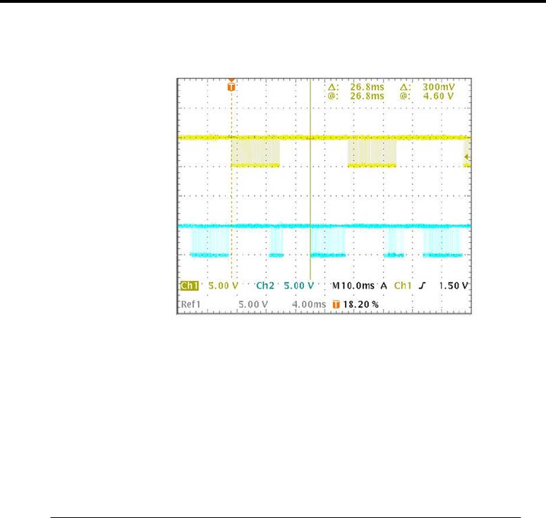
Experiment 2 – Data Transmission
Figure B2 – Plot of transmitted and received data after
setting the SY parameter to 20.
In Figure B1, where synchronization information was
transmitted with the data, 54.0 ms was required to transmit
each packet to the receiver. After adjusting the SY parameter to
stop sending synchronization information in the preamble,
Figure B2 shows that the same data transmission occurred in
only 26.8 ms.
MaxStream 9XStream™ Wireless OEM Module Manual v2.8
34 Confidential and Proprietary, ©MaxStream, Inc. 2001
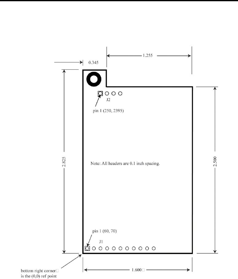
Appendix A – Packaging Information
Top view diagram of the 9XStream module
with pin layout and dimensions.

MaxStream 9XStream™ Wireless OEM Module Manual v2.8
35 Confidential and Proprietary, ©MaxStream, Inc. 2001
Appendix B – J1/J2 Pin Descriptions
Pin
No.
Pin Name I/O
Type
Description Active
1 _____
CTS
O
PU Clear to Send flow control low
2 SLEEP
(PWRDN)
I
PU
Can be used to enter Sleep Mode
(See “Modes of Operation” section for
details.)
high
3 DO
(Data Out)
O
PU
Data leaving the module that is sent
to the host high
4 DI
(Data In) I Data entering the 9XStream module
to be transmitted over the air high
5 RTS/CMD
I
PD
Command mode enable
(See “Binary Command Mode” section for
details.)
high
6
________
RESET I
PU Reset module low
7 RXLED O Indicates good RF data reception high
PWR - Indicates module powered
on high
8 ___
TX/PWR O ___
TX - Asserted during transmission ↓ low
9 _______
CONFIG
I
PU*
Hold low during power up or reset -
forces ASCII command mode. DO
NOT TIE TO
MICROPROCESSOR!
(See “Serial Port Operation” section for
details.)
low
10 VCC I +5 VDC -
11 GND - Signal ground -
PU – 10kΩ Pull-Up Resistor
PD – 10kΩ Pull-Down Resistor
* CONFIG signal has a 47kΩ Pull-Up Resistor
J2 Pin Descriptions
Pin Signal
1 GND
2 GND
3 GND
4 GND

MaxStream 9XStream™ Wireless OEM Module Manual v2.8
36 Confidential and Proprietary, ©MaxStream, Inc. 2001
Appendix C – Specifications
X09-009 X09-019
General
Frequency Range 902 to 928 MHz, unlicensed ISM Band
Type Frequency Hopping Spread Spectrum Transceiver
Frequency Control Direct FM
Transport Protocol Various Monitoring and Addressing Modes – see “Networking and
Addressing” section
Channel Capacity Hops through 25 channels. Features 7 different hop
sequences.
Serial Data Interface Asynchronous CMOS (TTL) signals, 5V levels
Serial Interface Baud
Rate
Configurable from 2400-
57600 bps
*1200 bps available
Configurable from 2400-
57600 bps
Data Throughput 9600 bps 19200 bps
Performance
Channel Data Rate 10k 20k
Transmit Power
Output
100mW 100mW
Rx Sensitivity -110 dBm –107 dBm
Range* Indoor: 600’ to 1500’
Outdoor: 7mi. with dipole,
over 20 mi. with high gain
antenna
Indoor: 425’to 1060’
Outdoor: 5 miles with dipole,
over 14 miles with high gain
antenna
Interference
Rejection
70 dB at pager and cellular phone frequencies
Power Requirements
Supply Voltage 5 VDC +/-0.25V
Current Consumption Tx – 150 mA nominal, Rx – 50 mA nominal
Power Down mode – less than 1 microamp
Other cyclic power-down modes available – see “Low Power
Modes” section
Physical Properties
Board Size 1.6” x 2.85” x .35” (4.06 x 6.86 x .89) cm
Weight 0.8oz (24g)
Connectors 11 pin and 4 pin 0.1” spaced male Berg type headers
Operating
Temperature
Standard: 0ºC to 70ºC
Industrial version: -40ºC to 85ºC available
Antennas
Antenna Connector MMCX Female or Reverse Polarity SMA Male
Approved Antennas Integral wire antenna (factory installed)
1/4 wave flexible monopole
1/2 wave flexible dipole, SMA
MaxStream 9XStream™ Wireless OEM Module Manual v2.8
37 Confidential and Proprietary, ©MaxStream, Inc. 2001
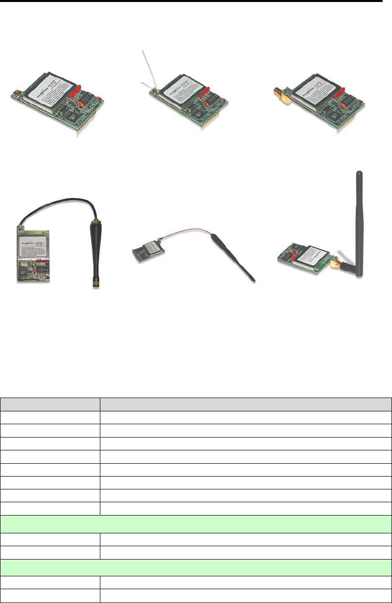
Appendix D – Product Listing
MMCX – No Antenna MMCX – Wire Antenna SMA – No Antenna
X09-009NM, X09-019NM X09-009WM, X09-019WM X09-009NS, X09-019NS
¼ Wave Antenna MMCX ½ Wave Antenna MMCX ½ Wave Antenna SMA
A09-QBMM-3-P6I A09-HBMM-7-P6I A09-HASM-675
900 MHz Modules
Product Code Description
X09-009NM 9600-baud, no wire mount antenna, MMCX connector
X09-009WM 9600-baud, wire mount antenna, MMCX connector
X09-009NS 9600-baud, no wire mount antenna, SMA connector
X09-009WS 9600-baud, wire mount antenna, SMA connector
X09-019NM 19200-baud, no wire mount antenna, MMCX connector
X09-019WM 19200-baud, wire mount antenna, MMCX connector
X09-019NS 19200-baud, no wire mount antenna, SMA connector
X09-019WS 19200-baud, wire mount antenna, SMA connector
Package Kits
X09-009PK 9600-baud, Package
X09-019PK 19200-baud, Package
Development Kits
X09-009DK 9600-baud, Development Kit
X09-019DK 19200-baud, Development Kit

MaxStream 9XStream™ Wireless OEM Module Manual v2.8
38 Confidential and Proprietary, ©MaxStream, Inc. 2001
Appendix D – Product Listing (cont.)
Antennas
Product Code Gain
(dBi)
Frequency
Range
(MHz)
Feed
Connect
or
Description
Yagi Antennas
A09-Y6 6.2 896 – 980 RPSMAF Yagi
A09-Y7 7.2 902 – 928 RPSMAF Yagi
A09-Y8 8.2 902 – 928 RPSMAF Yagi
A09-Y9 9.2 902 – 928 RPSMAF Yagi
A09-Y10 10.2 902 – 928 RPSMAF Yagi
A09-Y11 11.2 902 – 928 RPSMAF Yagi
A09-Y12 12.2 902 – 928 RPSMAF Yagi
A09-Y13 13.2 902 – 928 RPSMAF Yagi
A09-Y14 14.2 902 – 928 RPSMAF Yagi
A09-Y15 15.2 902 – 928 RPSMAF Yagi
A09-W7 7.2 902 – 928 RPSMA Base Station
A09-M7 7.2 902 – 928 RPSMA Base Station
A09-F2 2.2 902 – 928 RPSMA Base Station
A09-F5 5.2 902 – 928 RPSMA Base Station
A09-F8 8.2 902 – 928 RPSMA Base Station
A09-F9 9.2 902 – 928 RPSMA Base Station
Whip Antennas
A09-HASM-
675
2.1 902 – 928 RPSMA ½ wave Whip
A09-HBMM-7-
P6I
2.1 902 – 928 MMCX ½ wave Whip
A09-QBMM-3-
P6I
1.9 902 – 928 MMCX ¼ wave Whip
A09-QI 1.5 902 – 928 Integrated ¼ wave wire
NOTE: If using an external antenna, the wire antenna should be removed from the 9XStream
module.

MaxStream 9XStream™ Wireless OEM Module Manual v2.8
39 Confidential and Proprietary, ©MaxStream, Inc. 2001
Appendix E – 9XStream Commands
AT
Command
Binary
Command
Number
Version
Description Parameters
# Bytes
Returned
Factory
Default
DT 0
4.08 Set the Module Address. (Only
modules with the same address can
communicate.)
Range: 0 – FFFFH 2 0
SM
1 4.08 Adjust Sleep Mode Setting 0 - No Sleep
1 – Pin Sleep
2 – Serial Port Sleep
3 – Cyclic 0.5 second
4 – Cyclic 1.0 second
5 – Cyclic 2.0 second
6 – Cyclic 4.0 second
7 – Cyclic 8.0 second
1 0
ST 2 4.08 Set time to Sleep. Time of
inactivity before entering Sleep
Mode (This number is only valid
in Cyclic and Serial Port Sleep
settings).
Range: 10 – FFFFH
(tenths of a second)
2 64H
HT 3 4.08 Set time before long header. Time
of inactivity (no serial or over-the-
air data is transmitted or received)
before a long header is used. The
default value (FFFFH) means no
long header will be sent.
Range: 0 – FFFFH
(tenths of a second)
2 FFFFH
BT 4 4.08 Set silence time before command
sequence.
Range: 0 – FFFFH
(tenths of a second)
2 AH
AT 5 4.08 Set silence time after command
sequence.
Range: 0 – FFFFH
(tenths of a second)
2 AH
CT 6 4.08 Set time out from AT Command
Mode. Returns to Idle Mode from
AT Command Mode if no valid
commands have been received
within this time period.
Range: 0 – FFFFH
(tenths of a second)
2 C8H
FL 7 4.08 Set serial software flow control.
(Hardware flow control (CTS) is
always on.)
1- No software flow
control
1- use software
flow control
1 0
WR 8 4.08 Write all configurable parameters
to non-volatile memory. All
settable parameters are stored.
NA NA NA

MaxStream 9XStream™ Wireless OEM Module Manual v2.8
40 Confidential and Proprietary, ©MaxStream, Inc. 2001
Appendix E – 9XStream Commands (cont.)
AT
Command
Binary
Command
Number
Version
Description Parameters
# Bytes
Returned
Factory
Default
CN 9 4.08 Exit AT Command Mode. NA NA NA
E1 11 4.08 Enable character echo in AT
command mode.
NA NA NA
LH
12 4.08 Transmit header time. Used to
adjust the length of the long
header.
Range: 0 – FFH
(tenths of a second)
1 1H
FH 13 4.08 Force header on next transmit. NA NA NA
RE 14 4.08 Restore defaults configuration. NA NA NA
ER 15 4.08 Set Receive Error Count. This
value is reset to 0 after every reset.
It is not non-volatile. Once this
counter reaches FFFFH, it remains
there until reset.
Range: 0 – FFFFH 2 0
GD 16 4.08 Set Receive Good Count. This
value is reset to 0 after every reset.
It is not non-volatile. Once this
counter reaches FFFFH, it remains
there until reset.
Range: 0 – FFFFH 2 0
HP 17 4.08 Set Network number. Each
Network uses a different hop
sequence. Seven different
Network numbers are available.
This can be used to operate
independent networks of 9XStream
modules in the same vicinity.
Range: 0 – 6 1 0
MK 18 4.08 Set Module Address Mask. Only
bits set to ‘1’ are used in the
address comparison between the
transmitter’s address and that of
the receiver. A global address is
an address that has the same bits
set as the Address Mask.
Range: 0 – FFFFH 2 FFFFH
CC 19 4.08 Set command sequence character.
The parameters determine the
ASCII command sequence
character used to enter AT
Command Mode.
Range: 20H – 7FH 1 2BH
(‘+’)

MaxStream 9XStream™ Wireless OEM Module Manual v2.8
41 Confidential and Proprietary, ©MaxStream, Inc. 2001
Appendix E – 9XStream Commands (cont.)
AT
Command
Binary
Command
Number
Version
Description Parameters
# Bytes
Returned
Factory
Default
VR 20 4.08 Firmware version NA 2 NA
BD 21
4.08 Set Serial Baud Rate (bps). Use
to adjust the serial port baud
rate. The new baud rate will
not take effect until the ATCN
command is issued. If the BD
command is issued in Binary
Command Mode, it must be
stored using the WR command,
and the new baud rate will take
affect after resetting the
module.
Range: 1 - 6
1 - 2400
2 - 4800
3 - 9600
4 - 19200
5 - 38400
6 - 57600
1
RT 22
4.10 RTS/CMD Control. This
command must be used to turn
on binary programming if
Binary Command Mode will be
used. (By default, binary
programming is disabled, so
any commands sent in Binary
Command Mode will not be
understood until binary
programming is enabled.)
0 – Disable binary
programming.
1 – Enable binary
programming.
1 0
SY 23
4.12 Set Sync Timer. This time
represents the time that the
transmitter and receiver stay in
sync after receiving or sending
data. Setting this parameter to
20 (14H) will allow any module
to transmit within the next 2
seconds utilizing a header of
8ms instead of 35ms. Use this
parameter to speed up
communication latency and
turn-around time.
Range: 0 –FFH
(tenths of a second)
1 0
MaxStream 9XStream™ Wireless OEM Module Manual v2.8
42 Confidential and Proprietary, ©MaxStream, Inc. 2001
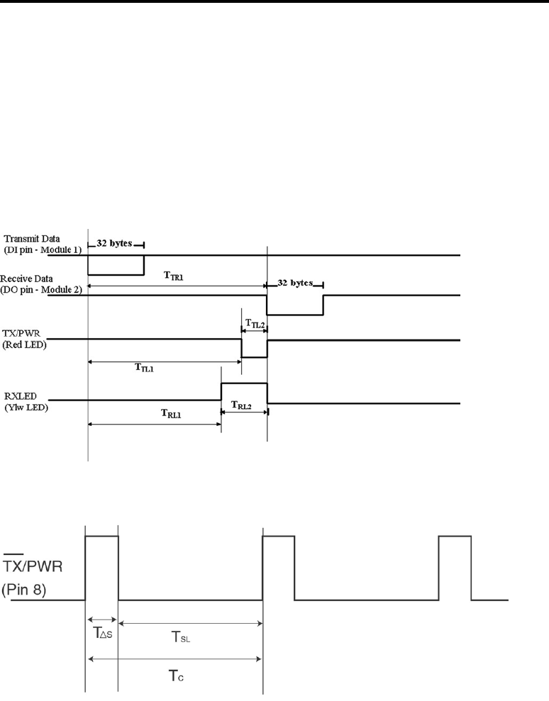
Appendix F – Timing Diagrams
Pin Timings
Sleep Mode Timings

MaxStream 9XStream™ Wireless OEM Module Manual v2.8
43 Confidential and Proprietary, ©MaxStream, Inc. 2001
Appendix G – Electrical Characteristics
DC Characteristics
(Vcc=4.75V to 5.25V)
Symbol Parameter Condition Min Typical Max Units
VIL Input Low
Voltage
All input signals -0.5 0.3*Vcc V
VIH
Input High
Voltage
________
(Except RESET) 0.6*Vcc Vcc+0.5 V
VIH2 Input High
Voltage
________
(RESET) 0.9*Vcc Vcc+0.5 V
VOL
Output
Low
Voltage
IOL=20mA Vcc=5V 0.6 V
VOH
Output
High
Voltage
IOH=-3mA Vcc=5V 4.2 V
IIL
Input
Leakage
Current I/O
Pin
Vcc=5V, pin low
(abs. value)
(Except CTS, DO,
RESET, CONFIG)
8.0 uA
IIH
Input
Leakage
Current I/O
Pin
Vcc=5V, pin high
(abs. value)
(Except RTS/CMD)
980 nA
IIL2
____ ________
CTS, DO, RESET
(Vcc-VI)/10 mA
IIL3 _________
CONFIG (Vcc-VI)/47 mA
IIH2 RTS/CMD VI/10 mA

MaxStream 9XStream™ Wireless OEM Module Manual v2.8
44 Confidential and Proprietary, ©MaxStream, Inc. 2001
Appendix G – Electrical Characteristics (cont.)
AC Characteristics
Pin Timings (SY=0)
Symbol Description X09-019 19200 Timing*
(B = Number of Bytes)
X09-
009
9600 Timing*
(B = Number of
Bytes)
(T measured in ms)
TR1 Latency from the
time data is
transmitted until
received.
54 ms For 0<B<64,
T=41.6+(0.4*B)
For B>63,
T=66.8 ms
72.0 ms For 0<B<40,
T=46.27+(0.73*B)
For B>=39 bytes,
T=74.8 ms
TTA1 Latency from when
serial data enters
the DI pin to when
it is actually
transmitted over-
the-air.
1.6 ms For all B,
T=1.6 ms
2.0 ms For all B,
T=2.0 ms
TTA2 Latency of over-
the-air data
transmission.
52.4 ms For all B,
T=38.8 + (0.4*B) +
0.8
70 ms For all B,
T=41.8+(0.8*B) +
1.6
TP1 Time duration of
header bits in data
packet.
31.04 ms For all B,
T=38.8 ms
41.8 ms For all B,
T=41.8 ms
TP2 Time duration of
data bits in data
packet.
12.8 ms For all B,
T=0.4B ms
25.6 ms For all B,
T=0.8B ms
TP3 Time duration of
CRC bits in data
packet.
0.83 ms For all B,
T=0.8 ms
1.6 ms For all B,
T=1.6 ms
TTL1 Time from when
data packet is
transmitted until
TX/PWR first
pulses low.
46.4 ms For 0<B<12,
T=37.8 ms
For 11<B<65,
T=33.3+(0.39*B) ms
For B>64,
T=58.4 ms
55.6 ms For 0<B<12,
T=39.8 ms
For 11<B<35,
T=30.52+(0.77*B)
For B>34 bytes,
T=56.8 ms
TTL2 Time that
TX/PWR pin is
driven low (when
red LED flashes).
8.4 ms For 0<B<14,
T=3.24+(0.4B)
For B>13,
T=8.48 ms
16.8 ms For 0<B<14,
T=6.5+(0.8*B) ms
For B>13,
T=16.8 ms

MaxStream 9XStream™ Wireless OEM Module Manual v2.8
45 Confidential and Proprietary, ©MaxStream, Inc. 2001
AC Characteristics
Pin Timings (SY=0) (cont.)
Symbol Description X09-019 19200 Timing*
(B = Number of Bytes)
X09-
009
9600 Timing*
(B = Number of
Bytes)
(T measured in ms)
TRL1 Time from when
data packet is
transmitted until
RXLED pin first
goes high on
receiver.
40.6 ms For all B,
T=39.6 ms
44.5 ms For all B,
T=44.5 ms
TRL2 Time that RXLED
pin is driven low
(when yellow LED
flashes).
13.6 ms For 0<B<65,
T=0.79+(0.408*B)
For B>64,
T=26.9 ms
25.6 ms For 0<B<37,
T=1.63+(0.794*B)
For B>36,
T=30.2 ms
* Note: The timing formulas are approximations over a specified range of bytes. They are
accurate to within 1 – 2 milliseconds.
Pin Timings (SY = 10)
Symbol Description X09-019 19200 Timing
Formulas*
(B = Number of Bytes)
X09-
009
9600 Timing
Formulas*
(B = Number of
Bytes)
(T measured in ms)
TR1 Latency from the
time data is
transmitted until
received.
12.2 ms For 0<B<9,
T=9.0+(0.4*B)
For B>8,
T=12.2 ms
19.4 ms For 0<B<6,
T=15.5+(0.775*B)
For B>5 bytes,
T=19.4 ms
TTA1 Latency from when
serial data enters
the DI pin to when
it is actually
transmitted over-
the-air.
1.6 ms For all B,
T=1.6 ms
2.0 ms For all B,
T=2.0 ms
TTA2 Latency of over-
the-air data
transmission.
32.8 ms For all B,
T=TP1+ (0.4*B) +
0.8
61.7 ms For all B,
T=TP1+(0.8*B) +
1.6
TP1 Time duration of
header bits in data
packet.
19.2 ms For B<9,
T=6.9 ms
For 8<B<29,
34.5 ms For B<6,
T=11.8 ms
For 5<B<22,

MaxStream 9XStream™ Wireless OEM Module Manual v2.8
46 Confidential and Proprietary, ©MaxStream, Inc. 2001
T=13.2 ms
For 28<B<54,
T=19.2 ms
T=23.2 ms
For 21<B<45,
T=34.5 ms
AC Characteristics
Pin Timings (SY=10) (cont.)
Symbol Description X09-019 19200 Timing
Formulas*
(B = Number of Bytes)
X09-
009
9600 Timing
Formulas*
(B = Number of
Bytes)
(T measured in ms)
TP2 Time duration of
data bits in data
packet.
12.8 ms For all B,
T=0.4B ms
25.6 ms For all B,
T=0.8B ms
TP3 Time duration of
CRC bits in data
packet.
0.83 ms For all B,
T=0.8 ms
1.6 ms For all B,
T=1.6 ms
TTL1 Time from when
data packet is
transmitted until
TX/PWR first
pulses low.
6.04 ms For all B,
T=6.04 ms
9.08 ms For all B,
T=9.08 ms
TTL2 Time that TX/PWR
pin is driven low
(when red LED
flashes).
6.44 ms For 0<B<9,
T=3.24+(0.4*B)
For B>8,
T=6.44 ms
11.3 ms For 0<B<6,
T= 6.5+(0.8*B)
ms
For B>5,
T=11.3 ms
TRL1 Time from when
data packet is
transmitted until
RXLED pin first
goes high on
receiver.
8.44 ms For all B,
T=8.44 ms
14 ms For all B,
T=14 ms
TRL2 Time that RXLED
pin is driven low
(when yellow LED
flashes).
4.28 ms For 0<B<10,
T 0.8+(0.4*B)
For B>9,
T=4.28 ms
5.68 ms For 0<B<6,
T=1.6+(0.82*B)
For B>5,
T=5.68 ms
* Note: The timing formulas are approximations over a specified range of bytes. They are
accurate to within 1 – 2 milliseconds.

MaxStream 9XStream™ Wireless OEM Module Manual v2.8
47 Confidential and Proprietary, ©MaxStream, Inc. 2001
Cyclic Sleep Mode Timings
Symbol Description 19200-baud 9600-baud
T∆S Time when module is listening for a valid
header to start receiving data.
100 ms 100 ms
TSL Time where the 9XStream is in its low
power cyclic sleep. This time is adjustable
using the SM command.
0.5 seconds
1.0 seconds
2.0 seconds
4.0 seconds
8.0 seconds
(depends on SM)
0.5 seconds
1.0 seconds
2.0 seconds
4.0 seconds
8.0 seconds
(depends on SM)
TC Total period between successive pulses of
the module awakening from Sleep Mode.
This value is dependent on the setting of the
SM command.
0.6 seconds
1.1 seconds
2.1 seconds
4.1 seconds
8.1 seconds
(depends on SM)
0.6 seconds
1.1 seconds
2.1 seconds
4.1 seconds
8.1 seconds
(depends on SM)

MaxStream 9XStream™ Wireless OEM Module Manual v2.8
48 Confidential and Proprietary, ©MaxStream, Inc. 2001
Appendix H – Sleep Mode Settings
Sleep
Settings
Transition to Sleep
Mode
Return to
Idle Mode
Sleep Current Configure
Commands
No
Sleep
Mode
None. The module
remains in Idle Mode.
(Default Setting)
-
50 mA
-
Pin
Sleep
High on SLEEP pin
(pin 2).
Low on
SLEEP pin.
<2 uA SM
Serial
Port
Sleep
Automatic transition
after a user-defined
period of module
inactivity (no
transmitting or
receiving of data). Set
by ST command.
Any serial
byte received
on DI pin.
1 mA SM, ST
Cyclic
Sleep
Automatic transition
after a user-defined
period of module
inactivity (no
transmitting or
receiving of data). Set
by ST command.
Periodically
returns to
Idle Mode
0.5 Cyclic:
Min: 60µA
Max: 40mA
Avg: 7.4mA
2.0 Cyclic:
Min: 60µA
Max: 35.7mA
Avg: 2.07mA
8.0 Cyclic:
Min: 60µA
Max: 35.56mA
Avg: 630 µA
1.0 Cyclic:
Min: 60µA
Max:
35.7mA
Avg: 4mA
4.0 Cyclic:
Min: 60µA
Max:
35.7mA
Avg: 1.1mA
SM, ST, LH,
HT
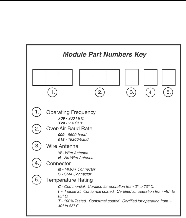
MaxStream 9XStream™ Wireless OEM Module Manual v2.8
49 Confidential and Proprietary, ©MaxStream, Inc. 2001
Appendix I – Module Part Numbers

MaxStream 9XStream™ Wireless OEM Module Manual v2.8
50 Confidential and Proprietary, ©MaxStream, Inc. 2001

MaxStream 9XStream™ Wireless OEM Module Manual v2.8
51 Confidential and Proprietary, ©MaxStream, Inc. 2001
Using the 9XStream Development Kit
Introduction:
Use this development kit to experience the extended range and ease of use of
the MaxStream 9XStream module. This module transmits data at either
9600 or 19200 bits per second (see FCC label on module shield) in the
license-free 900MHz ISM band. See how simple it is to communicate with
the module using asynchronous serial communications by following the
instructions below.
Contents:
2 9XStream Frequency Hopping modules
2 Interface Boards
2 9 VDC power supplies
2 DB-9 straight through serial cables
1 Null modem adapter
1 3.5" floppy disk containing file RAT.TXT
Requirements:
Two (2) computers with an available COM port and Windows 95/98
or NT.
Figure 1 – MaxStream PC
Interface Board

MaxStream 9XStream™ Wireless OEM Module Manual v2.8
52 Confidential and Proprietary, ©MaxStream, Inc. 2001
Instructions:
1. Assemble and Connect Interface Boards to computers.
a. Connect the modules to the Interface Boards by fitting the 4 and 11-pin
connectors into their respective female headers.
b. Attach the male sides of one of the DB-9 Connecting Cables to the
female DB-9 jacks on the Interface Boards.
c. Attach the female side of a DB-9 connecting cable to an available RS-
232 port on the back of Computer 1. Connect Module 2 to Computer 2
in the same fashion.
d. Plug power supplies into the Interface Boards. Turn the switch on. The
red LEDs on the Interface Boards will illuminate to show the boards
are powered.
e. Refer to figure 1 for completed assembly.
2. Run and configure HyperTrm.exe on both computers
a. Open the folder on the Start Menu found under Programs ->
Accessories -> Communications -> HyperTerminal.
b. Double-click on the application HyperTrm.exe and choose a
name and an icon for the new connection in the Connection
Description dialogue box.
c. In the Connect To dialogue box on each computer, select
Connect using: Direct to Com1 or Direct to Com2 to correspond
with the COM port used on the respective computers (see figure
2) . Click OK.
d. In the COM Properties dialogue box, set the following: Bits
per second: 19200; Data bits: 8; Parity: None; Stop Bits: 1 and
Flow Control: Hardware (See figure 3). Click OK. (Set the Bits
per second to 9600 if you are using 9XStream-96 modules)
e. Both computers are now set up and ready to communicate.
Figure 2 –Connect To Dialogue
Box
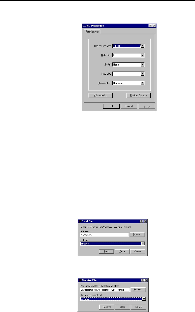
MaxStream 9XStream™ Wireless OEM Module Manual v2.8
53 Confidential and Proprietary, ©MaxStream, Inc. 2001
Instructions (cont.)
3. Test Connection
a. Place cursor in HyperTerminal window of Computer 1 and type
a message. Notice that text appears only in the window of
Computer 2 and text typed on Computer 2 appears only on
Computer 1. This text is being transferred over the air by the
9XStream modules.
b. Transfer the file RAT.TXT
i. On Computer 1: Select Transfer menu -> Send File(or
try right-clicking in the HyperTerminal window). Insert
the disk into the A: drive and enter Filename:
A:\RAT.TXT Select Protocol: Ymodem (See figure 4).
Press Send.
Figure 3 – COM Properties
Dialo
g
ue Box
Figure 4 – Send File Dialogue
Box
Figure 5 – Receive File
Dialogue Box

MaxStream 9XStream™ Wireless OEM Module Manual v2.8
54 Confidential and Proprietary, ©MaxStream, Inc. 2001
Instructions (cont.)
ii. On Computer 2: Select Transfer menu -> Receive File.
Select a folder in which to place the file and select
Protocol: Ymodem (see figure 5). Press Receive.
iii. The file will begin to transfer and any errors or retries
will be accounted for. Touch the antennas and move the
modules around to notice that errors or retries do occur
under certain circumstances.
iv. When the transfer completes, open RAT.TXT on
Computer 2 and observe the pattern of text, it will be
easy to see if any characters were lost or corrupted.
v. Any file can be transferred this way. Use either
Xmodem or Ymodem protocol. Both computers must
have the same settings.
c. Try range testing by distancing the two computers from each
other. The modules can send and receive data up to 10 miles line
of sight using gain antennas.
4. Problems (Trouble Shooting)
a. Can’t find the HyperTerminal on your computer?
i. Search your hard drive for HyperTrm.exe
ii. Download a free version from http://www.hilgraeve.com
b. Power LED doesn’t illuminate when battery clip is attached?
i. Replace the battery.
c. Cannot connect to the comm port or communication not working?
i. Try selecting another comm port by selecting Properties
under the File menu.
ii. If necessary test the comm ports with a null modem cable
(cross RX and TX) between the two computers to verify
operation of comm ports.
d. Characters are getting scrambled?
i. Verify that both comm ports are set match the baud rate of the
modules being tested. Probably 9600 baud or 19200 bits per
second. Look for the baud rate on the FCC sticker, 96 or 192
respectively.

MaxStream 9XStream™ Wireless OEM Module Manual v2.8
55 Confidential and Proprietary, ©MaxStream, Inc. 2001
Index
Addressing, 2, 9, 22, 36
Alphanumeric, 19
Antenna, 4, 8, 11, 25, 30, 36, 37, 38
ASCII, 19, 35, 41
Asserted, 9, 10, 15, 17, 20, 21, 26, 28
Asynchronous, 5, 7, 8, 49
AT commands, 18, 19, 20, 26, 27
Authorization, 25
Baud rate, 8, 9, 10, 13, 29, 42, 52
Binary commands, 18, 26, 28
Clear to send, 26
CMD, 7, 10, 20, 21, 26, 28, 44
CMOS, 7
CMOS logic, 26, 28
COM port, 7
Command Mode, 2, 10, 18, 19, 20, 21, 26, 35,
40, 41, 42
Command table, 26
Communicate, 7, 17, 22, 28, 29, 39, 49, 50
Communications, 4, 23, 26, 27, 49
CONFIG, 7
CRC, 11, 13, 14, 26, 27
CTS, 7, 8, 9
CTS pin, 9, 15, 17, 26, 27
Cyclic redundancy check (CRC), 26
Cyclic sleep, 26
Data buffer, 26
Data packets, 8, 9, 11, 12, 13, 17, 18, 26, 45
Data validity, 27
De-asserted, 15, 17, 20, 28
DI pin, 7, 8, 10, 11, 15, 17, 27, 29, 46
DO pin, 7, 9, 14, 21, 27
FCC, 2, 4, 5, 6, 7, 25, 27, 49, 52
FCC Compliance, 4
FCC Rules, 4
FHSS, 6, 27
Flow control, 27
Frequency Hopping Spread Spectrum
(FHSS), 27
Half-duplex, 5, 8, 27
Hardware flow control, 27, 40
Header, 11, 12, 13, 17, 18, 26, 27, 28, 31, 39,
40, 42, 45
HEX, 19, 20, 24
HyperTerminal, 26, 27, 50, 51, 52
Idle Mode, 2, 11, 14, 15, 17, 20, 27, 28, 29, 40,
46
Industrial Temperature, 27
Integration, 2, 6, 28
Interface board, 28
Interference, 4, 6, 23
Label, 4
Latency, 13, 42
Least Significant Byte, 19, 21
Licensing, 6
Long header, 28
Low-asserted, 7, 10, 26
Low-power modes, 6, 28
LSB, 19
Module Address Mask, 2, 23, 24, 28, 41
Module Address Masks, 23, 28
Module Addresses, 22, 23, 28
MSB (Most Significant Byte) , 19
Networking, 2, 6, 9, 22, 36
Networks, 2, 22, 23, 28
OEM, 4
Packet, 12, 13, 14, 17, 18, 23, 26, 28, 29, 31
PC Serial Port, 6
Pin layout, 28
Pin sleep, 28, 29
Product Integration, 6
Receive Mode, 2, 11, 14, 15, 17, 28
Receiver Module Address, 23, 24
Redundancy, 13, 14, 26
RS-232, 7
RS-232 logic, 28
RTS, 2, 7, 10, 18, 20, 21, 26, 28, 35, 42, 44
RTS/CMD (Request to Send/Command), 2, 7,
10, 18, 20, 21, 26, 28, 35, 42, 44
Sensitivity, 28, 30, 36
Serial data, 29
Serial Pins, 7
Serial Port, 7
Serial port sleep, 29
Sleep Mode, 2, 15, 17, 21, 26, 28, 29, 35, 39, 43,
45, 46
SLEEP pin., 46
SM command, 15, 17, 20, 28, 29, 45
Spread spectrum, 7
Standby Mode, 29
Start bit, 29
Stop bit, 8, 29
Synchronization, 13, 17, 23, 29, 31
Transmission Latency, 2, 13, 29
Transmit, 5, 7, 8, 9, 15, 23, 26, 27, 30, 31, 40,
42
Transmit Mode., 11
Transmitter Module Address, 23, 24
TTL (Transistor-transistor logic), 29
UART, 6, 7, 8
VID, 2, 22, 23, 27, 29
VID (Vendor Identification number), 29
VID Request Form, 22
volatile memory, 18, 20, 21, 40

MaxStream 9XStream™ Wireless OEM Module Manual v2.8
56 Confidential and Proprietary, ©MaxStream, Inc. 2001