MaxStream 9XTREAM User Manual manual
MaxStream Inc. manual
Contents
- 1. Users Manual
- 2. Revised Users manual
- 3. Revised users manaual
Users Manual

CDH Communications
9Xtream
Frequency Hopping Data Radio
CDH Communications
3471 N. 1730 W.
Pleasant Grove, UT 84062
Phone: (801)796-5566
Fax: (801) 796-5525
http://www.cdhcommunications.com
CDH Communications
CDH Communications
3471 N. 1370 W.
Pleasant Grove, UT 84062
(801)796-5566
9Xtreme Frequency Hopping Data Radio
FCC Compliance Warning:
Changes or modifications to the 9Xtreme Data Radio not expressly approved by CDH
Communications, Inc. could void the user’s authority to operate this product.
Note: This equipment has been tested and found to comply with the limits for a Class B
digital device, pursuant to part 15 of the FCC Rules. These limits are designed to provide
reasonable protection against harmful interference in a residential installation. This
equipment generates, uses, and can radiate radio frequency energy and, if not installed
and used in accordance with the instructions, may cause harmful interference to radio
communications. However, there is no guarantee that interference will not occur in a
particular installation. If this equipment does cause harmful interference to radio or
television reception, which can be determined by turning the equipment off and on, the
user is encouraged to try to correct the interference by one or more of the following
measures:
• Reorient or relocate the receiving antenna.
• Increase the separation between the equipment and receiver.
• Connect the equipment into an outlet on a circuit different from that to which the
receiver is connected.
• Consult the dealer or an experienced radio/TV technician for help.
This device complies with part 15 of the FCC Rules. Operation is subject to the following
two conditions:
(1) This device may not cause harmful interference, and
(2) This device must accept any interference received, including interference that
may cause undesired operation.

CDH Communications
Introduction
The CDH Communications 9Xtreme is a frequency hopping data transceiver radio
designed for integration with other products. The 9Xtreme operates within the 900 MHz
ISM Band under Part 15 of the FCC Rules and Regulations.
The 9Xtreme allows OEMs to integrate the radio into their own systems. When installed
using a CDH Communications approved antenna, the system integrator needs to make
sure the 9Xtreme’s FCC label, or a copy of that FCC label, is clearly visible on the
outside of the integrated product.
Caution: If this radio is integrated into another product, the system integrator is
responsible for complying with the external labeling requirements as directed in the FCC
Rules and Regulations Part 15.19. The system integrator may only use antennas that
have been tested and approved with this radio to maintain the FCC approval. If a system
integrator uses a non-approved antenna they are responsible for obtaining their own
FCC certification. The radio also requires +5V source voltage. Any voltage higher than
5.5V will damage the radio.
Approved Antennas
Mfr Model Freq Gain Type Connector Dimensions
Astron AXQ900
PTL 902-928 2dBi Omni MMCX 3”
Astron AXH900 RP
SMA R 902-928 2dBi Omni Reverse
Polarity SMA 6.5”
CDH 900CDAN 902-928 2dBi Omni Integrated 3”
In order to comply with the FCC RF exposure requirements the Data Radio must be
installed with the antennas listed above and a minimum separation distance of 20 cm
must be maintained from the antenna to any near by persons.
The Radio uses an asynchronous serial interface with a start bit, stop bit and eight (8)
data bits at TTL levels for communicating with the host system. Using an RS232 driver
chip (such as a Maxim MAX232) the Radio can communicate directly to a standard
Serial Communications Port on a PC. See the section titled Demo Kit Instructions for a
tutorial to help get started using the 9Xtreme Radio.
9Xtreme Features:
• Frequency Hopping Spread Spectrum (FHSS) technology
• Secure over the air data encryption
• Resistant to noise and interference.
• 130mW transmit power
• 25 mile (40 Kilometer) effective range (line of sight)
CDH Communications
• Broadcast (promiscuous) networking protocol – data sent to the serial port on one
radio will be presented out of the serial port on all other radios that are within range
and have the same group code.
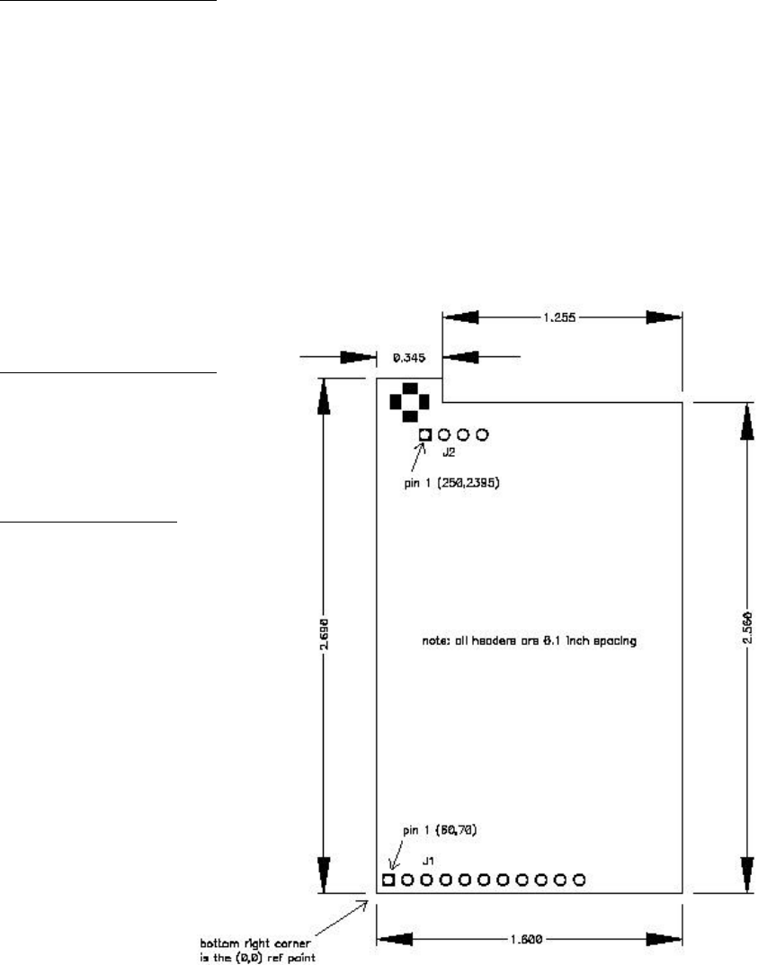
Connections
The Data Radio is connected to a host device using the 11 pin and the 4 pin berg headers.
These connections provide the radio with the required DC power source (+5V) and allow
the Data Radio to be programmed, configured and provide the I/O lines for the
asynchronous line level (TTL) RS-232 connection.
J1 PIN DESCRIPTIONS
J1-1 CTS Clear to send flow control (output)
J1-2 INT1 Interupt line to radio processor (input, not currently
implemented)
J1-3 TX Asyncronous data output (data going from radio to user)
J1-4 RX Asyncronous data input (data going from user to radio)
J1-5 RTS Ready to send flow control (input, not currently implemented)
J1-6 *RESET Reset line to radio processor (pull low to reset radio processor)
J1-7 MOSI SPI data in (input, not currently implemented)
J1-8 MISO SPI data out (output, not currently implemented)
J1-9 SCK SPI data clock (input/output, not currently implemented)
J1-10 Power +5 volts DC. (55mA in RX mode, 200mA in TX mode)
J1-11 Ground
J2 PIN DESCRIPTIONS
J2-1 Ground
J2-2 Ground
J2-3 Ground
J2-4 Ground
Antenna Connection
Female MMCX
CDH Communications
Specifications
Frequency Range: 902 to 928 MHz ISM Band
Radio Power Source: 5 VDC 200mA
Demo Kit Power Source: 6-15 VDC 200mA
Antenna Impedance: 50 Ohms unbalanced
Antenna Connection: MMCX female
Operation Mode: Frequency Hopping Spread Spectrum
Sensitivity: -111 dBm
Selectivity: 70 dB at pager and cellular frequencies
FCC Compliance: Part 15
Transport Protocol: Transparent
Data Interface: Asynchronous Serial TTL
RF Data Rate: 9600 bps
Data Interface Rates: 9600 or 19,200 bps
Data Protocol: 8 data bits, no parity, 1 stop bit, transparent
(no protocol).
Operating Temperatures: -40°C to 85°C, (-40°F to 185°F)
Size: 1.6 in. x 2.7 in. x .35 in.
CDH Communications
Using the 9Xtream Demo Kit
Introduction:
Use this demo kit to experience the power and sensitivity of
the CDH 9Xtream radio. This radio transmits data at 19200
bits per second in the license-free 900MHz ISM band. See how
simple it is to communicate with the radio using asynchronous
serial communications by following the instructions below.
Contents:
29Xtream Frequency Hopping 900MHz 19200bps
radios
2Demo Boards
2Battery clips with 9-volt battery
2 DB-9 connecting cables
2DB-25 to DB-9 converters
13.5" floppy disk containing file RAT.TXT
Requirements:
2 computers with an available comm port and Windows 95/98 or
NT.
Instructions:
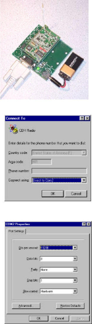
1. Assemble and Connect Demo Boards to computers.
a. Connect the radios to the Demo Boards by fitting the 4
and 11-pin connectors into their respective female
headers.
b. Attach the male sides of one of the DB-9 Connecting
Cables to the female DB-9 jacks on the Demo Boards.
c. Attach the female side of a DB-9 connecting cable to an
available comm port on the back of Computer 1.
Connect Radio 2 to Computer 2 in the same fashion.
d. Plug Battery clips into the Demo Boards. The green
LEDs on the Demo Boards will illuminate to show the
boards are powered.
e. Refer to figure 1 for completed assembly.
2. Run and configure HyperTrm.exe on both computers
a. Open the folder on the Start Menu found under
Programs -> Accessories -> Communications ->
HyperTerminal.
b. Double-click on the application HyperTrm.exe and
choose a name and an icon for the new connection in
the Connection Description dialogue box.
c. In the Connect To dialogue box on each computer,
select Connect using: Direct to Com1 or Direct to
Com2 to correspond with the comm port used on the
respective computers (see figure 2) . Click OK.
d. In the COM Properties dialogue box, set the
following: Bits per second: 19200; Data bits: 8; Parity:
None; Stop Bits: 1 and Flow Control: Hardware (See
figure 3). Click OK.
Figure 1– Demo Kit
Figure 2 –Connect To Dialogue
Box
Figure 3 – COM Properties
Dialogue Box
CDH Communications
e. Both computers are now set up and ready to communicate.
3. Test Connection
a. Place cursor in HyperTerminal window of Computer 1 and type a message. Notice that
text appears only in the window of Computer 2 and text typed on Computer 2 appears
only on Computer 1. This text is being transferred over the air by the CDH 9Xtream
radios.
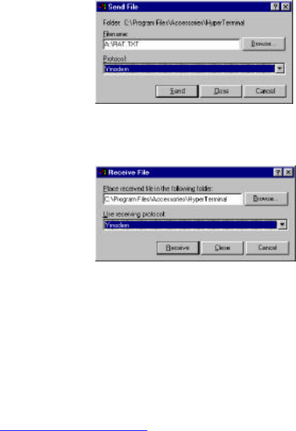
b. Transfer the file RAT.TXT
i. On Computer 1: Select Transfer menu -> Send File(or try right-clicking in the
HyperTerminal window). Insert the disk into
the A: drive and enter Filename:
A:\RAT.TXT Select Protocol: Ymodem (See
figure 4). Press Send.
ii. On Computer 2: Select Transfer menu ->
Receive File. Select a folder in which to
place the file and select Protocol: Ymodem
(see figure 5). Press Receive.
iii. The file will begin to transfer and any errors
or retries will be accounted for. Touch the
antennas and move the radios around to
notice that errors or retries do occur under
certain circumstances.
iv. When the transfer completes, open
RAT.TXT on Computer 2 and observe the
pattern of text, it will be easy to see if any
characters were lost or corrupted.
v. Any file can be transferred this way. Use
either Xmodem or Ymodem protocol. Both
computers must have the same settings.
c. Try range testing by distancing the two computers from each other. The radios can send
and receive data over 20 miles line of sight.
4. Problems (Trouble Shooting)
a. Can’t find the HyperTerminal on your computer?
i. Search your hard drive for HyperTrm.exe
ii. Download a free version from http://www.hilgraeve.com
b. Power LED doesn’t illuminate when battery clip is attached?
i. Replace the battery.
c. Cannot connect to the comm port or communication not working?
i. Try selecting another comm port by selecting Properties under the File menu.
ii. If necessary test the comm ports with a null modem cable (cross RX and TX)
between the two computers to verify operation of comm ports.
d. Some characters come through but not all?
i. Verify that both comm ports are set to 19200 bits per second.
Figure 4 – Send File Dialogue
Box
Figure 5 – Receive File
Dialogue Box