MaxStream XBEE XBEE OEM RF MODULE User Manual product manual XBee XBee PRO OEM RF Modules
MaxStream Inc. XBEE OEM RF MODULE product manual XBee XBee PRO OEM RF Modules
Contents
- 1. USERS MANUAL
- 2. users manual
- 3. Revised Used Manual
- 4. User Manual
USERS MANUAL
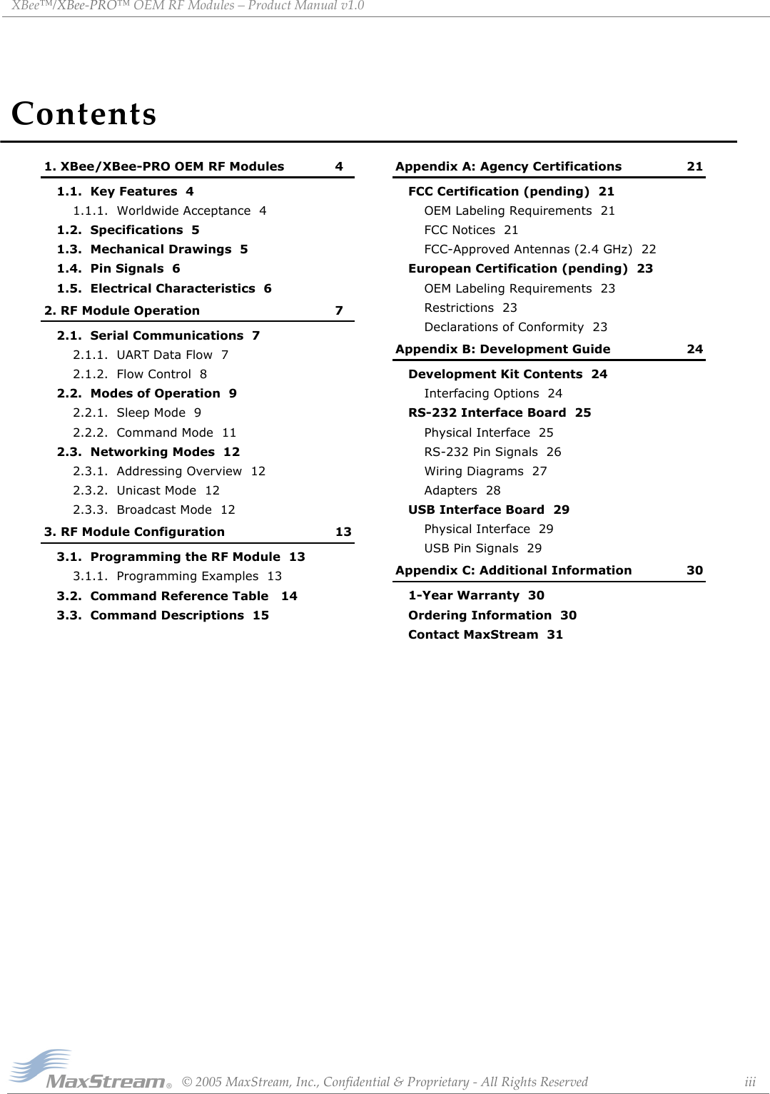
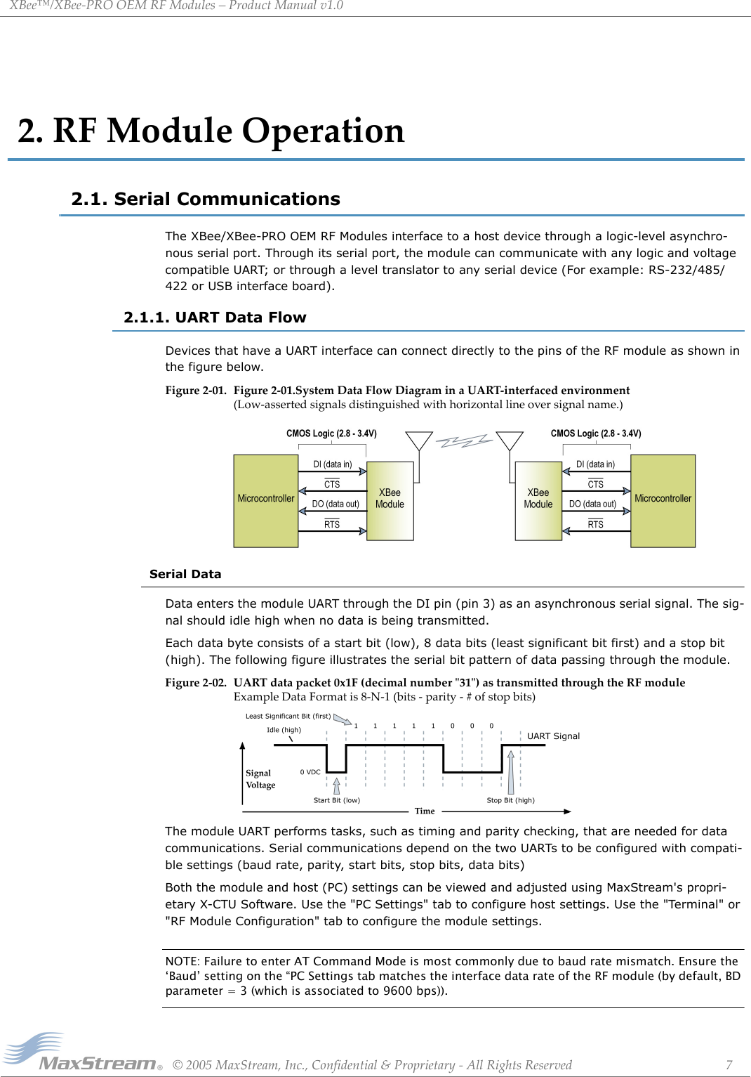
![XBee™/XBee‐PROOEMRFModules–ProductManualv1.0©2005MaxStream,Inc.,Confidential&Proprietary‐AllRightsReserved 41.XBee/XBee‐PROOEMRFModulesXBee and XBee-PRO Modules were engineered to meet ZigBee/IEEE 802.15.4 standards and address the unique needs of low-cost, low-power wireless sensor networks. The modules require minimal power and provide reliable delivery of critical data between devices. The modules operate within the ISM 2.4 GHz frequency band and are pin-for-pin compatible with each other.1.1. Key FeaturesHigh Performance, Low CostXBee• Indoor/Urban: up to 100’ (30 m)• Outdoor line-of-sight: up to 300’ (100 m)• Transmit Power: 1 mW (0 dBm)• Receiver Sensitivity: -92 dBmXBee-PRO• Indoor/Urban: up to 300’ (100 m)• Outdoor line-of-sight: up to 4000’ (300 m)• Transmit Power: 100 mW (20 dBm) EIRP• Receiver Sensitivity: -100 dBmRF Data Rate: 250,000 bpsAdvanced Networking & SecurityRetries and AcknowledgementsDSSS (Direct Sequence Spread Spectrum)13 direct sequence channels, each with over 65,000 unique network addresses availablePoint-to-point, point-to-multipoint and peer-to-peer topologies supportedUnicast and Broadcast Modes supported128-bit Encryption (downloadable firmware version coming soon)Self-routing/Self-healing mesh networking (downloadable firmware version coming soon)Low PowerXBee• TX Current: 45 mA (@3.3 V)• RX Current: 50 mA (@3.3 V)• Power-down Current: < 10 µAXBee-PRO• TX Current: 270 mA (@3.3 V)• RX Current: 55 mA (@3.3 V)• Power-down Current: < 10 µA Easy-to-UseNo configuration necessary for out-of box RF communicationsFree X-CTU Software (Testing and configuration software)Small form factorNetwork compatible with other ZigBee/802.15.4 devicesFree & Unlimited Technical Support1.1.1. Worldwide AcceptanceFCC Approval pending (USA) Refer to Appendix A [p21] for FCC Requirements. Systems that include XBee/XBee-PRO Modules inherit MaxStream’s Certifications.ISM (Industrial, Scientific & Medical) 2.4 GHz frequency bandManufactured under ISO 9001:2000 registered standardsXBee/XBee-PRO RF Modules are optimized for use in US, Canada, Australia, Israel and Europe (contact MaxStream for complete list of approvals).](https://usermanual.wiki/MaxStream/XBEE.USERS-MANUAL/User-Guide-585645-Page-4.png)
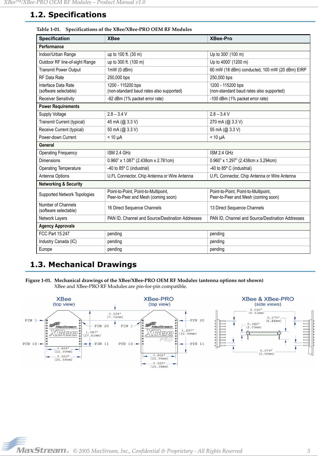
![XBee™/XBee‐PROOEMRFModules–ProductManualv1.0©2005MaxStream,Inc.,Confidential&Proprietary‐AllRightsReserved 61.4. Pin SignalsFigure1‐02. XBee/XBee‐PRORFModulePinNumber(topsidesshown‐shieldsonbottom)‐Minimumconnectionsare:VCC,GND,DOUTandDIN.‐SignalDirectionisspecifiedwithrespecttothemodule‐Functionslistedindescriptionsaresoftwareselectableandmaynotallbeavailableattimeofrelease.‐Moduleincludesa50kpull‐upresistorattachedtoRESET.‐UnusedinputsshouldbetiedtoGND/Unusedoutputsshouldbeleftdisconnected.1.5. Electrical CharacteristicsTable1‐02. PinAssignmentsfortheXBeeandXBee‐PROModules (Low‐assertedsignalsaredistinguishedwithahorizontallineabovesignalname.)Pin # Name Direction Description1 VCC - Power supply2 DOUT Output UART Data Out3 DIN / CONFIG Input UART Data In4 CD / DOUT_EN / DO8 Output Carrier Detect, TX_enable or Digital Output 85RESET Input Module Reset6 PWM0 / RSSI Output PWM Output 0 or RX Signal Strength Indicator7 [reserved] - Do not connect8 [reserved] - Do not connect9 DTR / SLEEP_RQ / DI8 Input Pin Sleep Control Line or Digital Input 810 GND - Ground11 AD4 / DIO4 / RF_TX Either Analog Input 4, Digital I/O 4 or Transmission Indicator12 DIO7 / CTS Either Digital I/O 7 or Clear-to-Send Flow Control13 ON / SLEEP Output Module Status Indicator14 VREF Input Voltage Reference for A/D Inputs15 AD5 / DIO5 / Associate Either Analog Input 5, Digital I/O 5 or Associated Indicator16 AD6 / DIO6 / RTS Either Analog Input 6, Digital I/O 6 or Request-to-Send Flow Control17 AD3 / DIO3 / COORD_SEL Either Analog Input 3, Digital I/O 3 or Coordinator Select18 AD2 / DIO2 Either Analog Input 2 or Digital I/O 219 AD1 / DIO1 Either Analog Input 1 or Digital I/O 120 AD0 / DIO0 Either Analog Input 0 or Digital I/O 0Table1‐03. DCCharacteristicsoftheXBee&XBee‐PRO(VCC=2.8‐3.4VDC)Symbol Parameter Condition Min Typical Max UnitsVIL Input Low Voltage All Digital Inputs - - 0.35 * VCC VVIH Input High Voltage All Digital Inputs 0.7 * VCC - - VVOL Output Low Voltage IOL = 2 mA, VCC >= 2.7 V --0.5VVOH Output High Voltage IOH = -2 mA, VCC >= 2.7 V VCC - 0.5 - - VIIIN Input Leakage Current VIN = VCC or GND, all inputs, per pin - 0.025 1 uAIIOZ High Impedance Leakage Current VIN = VCC or GND, all I/O High-Z, per pin - 0.025 1 uATX Transmit Current VCC = 3.3 V - 45(XBee)270(PRO) -mARX Receive Current VCC = 3.3 V - 50(XBee)55(PRO) -mAPWR-DWN Power-down Current SM parameter = 1 - < 10 - uA](https://usermanual.wiki/MaxStream/XBEE.USERS-MANUAL/User-Guide-585645-Page-6.png)
![XBee™/XBee‐PROOEMRFModules–ProductManualv1.0©2005MaxStream,Inc.,Confidential&Proprietary‐AllRightsReserved 82.1.2. Flow ControlFigure2‐03. InternalDataFlowDiagramDI (Data In) BufferWhen serial data enters the RF module through the DI Pin, the data is stored in the DI Buffer until it can be transmitted.When the RO (Packetization Timeout) parameter threshold is satisfied [refer to RO command description for more information], the module attempts to initialize an RF connection. If the mod-ule cannot immediately transmit (for instance, if it is already receiving RF data), the serial data continues to be stored in the DI Buffer. If the DI buffer becomes full, hardware or software flow control must be implemented in order to prevent overflow (loss of data between the host and the module).How to eliminate the need for flow control:Case in which the DI Buffer may become full and possibly overflow:Refer to the BD (Interface Data Rate) [p15] and RO (Packetization Timeout) [p19] command descrip-tions for more information.DO (Data Out) BufferWhen RF data is received, the data enters the DO buffer and is sent out the serial port to a host device. Once the DO Buffer reaches capacity, any additional incoming RF data is lost.If the module is receiving a continuous stream of RF data, any serial data that arrives on the DI pin is placed in the DI Buffer. The data in the DI buffer will be transmitted over-the-air when the module is no longer receiving RF data in the network.Two cases in which the DO Buffer may become full and possibly overflow:1. Send messages that are smaller than the DI buffer size.2. Interface at a lower baud rate [BD (Interface Data Rate) parameter] than the RF data rate.If the module is receiving a continuous stream of RF data, any serial data that arrives on the DI pin is placed in the DI Buffer. The data in the DI buffer will be transmitted over-the-air when the module is no longer receiving RF data in the network.1. If the RF data rate is set higher than the interface data rate of the module, the module will receive data from the transmitting module faster than it can send the data to the host.2. If the host does not allow the module to transmit data out from the DO buffer because of being held off by hardware or software flow control.](https://usermanual.wiki/MaxStream/XBEE.USERS-MANUAL/User-Guide-585645-Page-8.png)
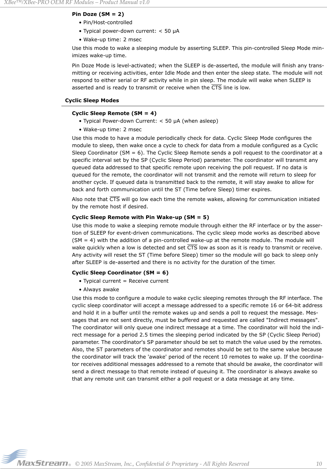
![XBee™/XBee‐PROOEMRFModules–ProductManualv1.0©2005MaxStream,Inc.,Confidential&Proprietary‐AllRightsReserved 92.2. Modes of OperationXBee/XBee-PRO RF Modules operate in five modes.Figure2‐04. XBee/XBee‐PRORFModuleModesofOperation (TheRFModulesoperateinonemodeatatime.)When not receiving or transmitting data, the RF mod-ule is in Idle Mode. The RF module shifts into the other modes of operation under the following conditions:• Serial data is received in the DI Buffer (Transmit Mode)• Valid RF data is received through the antenna (Receive Mode)• Sleep Mode condition is met (Sleep Mode)• Command Mode Sequence is issued (Command Mode)2.2.1. Sleep ModeSleep Modes enable the RF module to enter states of low-power consumption when not in use. In order to enter Sleep Mode, one of the following conditions must be met (in addition to the module having a non-zero SM parameter value):• SLEEP (pin 9) is de-asserted.• The module is idle (no data transmission or reception) for the amount of time defined by the ST (Time before Sleep) parameter. [NOTE: ST is only active when SM = 4-8.]The SM command is central to setting Sleep Mode configurations. By default, Sleep Modes are dis-abled (SM = 0) and the module remains in Idle/Receive Mode. When in this state, the module is constantly ready to respond to serial or RF activity.Pin/Host-controlled Sleep ModesPin Hibernate (SM = 1)• Pin/Host-controlled• Typical power-down current: < 10 µA (@3.0 VCC)• Wake-up time: 13.2 msecUse this mode to wake a sleeping module by asserting SLEEP. Pin Hibernate Mode minimizes qui-escent power (power consumed when in a state of rest or inactivity).Pin Hibernate Mode is level-activated; when SLEEP is de-asserted, the module will finish any transmitting or receiving activities, enter Idle Mode and then enter the state of sleep. The module will not respond to either serial or RF activity while in pin sleep. The module will wake when SLEEP is asserted and is ready to transmit or receive when the CTS line is low.Table2‐01. SleepModeConfigurationsSleep Mode SettingTransition into Sleep ModeTransition out of Sleep Mode Characteristics RelatedCommandsPowerConsumptionPin Hibernate (SM = 1) De-assert SLEEP Assert SLEEP Pin/Host-controlled (SM) < 10 µA (@3.0 VCC)Pin Doze (SM = 2) De-assert SLEEP Assert SLEEP Pin/Host-controlled (SM) < 50 µACyclic Sleep (SM = 4 - 6)Automatic transition to Sleep Mode as defined by the SM (Sleep Mode) and ST (Time before Sleep) parameters.Transition occurs after the cyclic sleep time interval elapses. The time interval is defined by the SP (Cyclic Sleep Period) parameter.RF Module wakes in pre-determined time intervals to detect if RF data is present.(SM), SP, ST < 50 µA when sleeping](https://usermanual.wiki/MaxStream/XBEE.USERS-MANUAL/User-Guide-585645-Page-9.png)
![XBee™/XBee‐PROOEMRFModules–ProductManualv1.0©2005MaxStream,Inc.,Confidential&Proprietary‐AllRightsReserved 112.2.2. Command ModeTo modify or read RF Module parameters, the module must first enter into Command Mode - a state in which incoming characters are interpreted as commands. A robust set of AT Commands are available for programming and customizing the module. AT CommandsTo Enter AT Command Mode:Default AT Command Mode Sequence (for transition to Command Mode):• No characters sent for one second [GT (Guard Times) parameter = 0x3E8]• Input three plus characters (“+++”) within one second [CC (Command Sequence Character) parameter = 0x2B.]• No characters sent for one second [GT (Guard Times) parameter = 0x3E8]All of the parameter values in the sequence can be modified to reflect user preferences.To Send AT Commands:Figure2‐05.SyntaxforsendingATCommandsTo read a parameter value stored in the RF module’s register, leave the parameter field blank.The preceding example would change the RF module Destination Address (Low) to “0x1F”. To store the new value to non-volatile (long term) memory, subsequently send the WR (Write) com-mand.For modified parameter values to persist in the module’s registry, changes must be saved to non-volatile memory using the WR (Write) Command. Otherwise, parameters are restored to previ-ously saved values after the module is powered off and then on again (or re-booted).System Response. When a command is sent to the RF module, the module will parse and exe-cute the command. Upon successful execution of a command, the module returns an “OK” mes-sage. If execution of a command results in an error, the module returns an “ERROR” message.To Exit AT Command Mode:For an example that illustrates programming the RF module using AT Commands, refer to the "RF Module Configuration" chapter [p13].Send the 3-character command sequence “+++” and observe guard times before and after the command characters. [Refer to the “Default AT Command Mode Sequence” below.]Send AT commands and parameters using the syntax shown below.1. Send ATCN (Exit Command Mode) Command. [OR]2. If no valid AT Commands are received within the time specified by CT (Command Mode Timeout) Command, the RF module automatically returns to Idle Mode.](https://usermanual.wiki/MaxStream/XBEE.USERS-MANUAL/User-Guide-585645-Page-11.png)
![XBee™/XBee‐PROOEMRFModules–ProductManualv1.0©2005MaxStream,Inc.,Confidential&Proprietary‐AllRightsReserved 122.3. Networking ModesBefore transmitting data over-the-air, the RF module will first undergo CCA (Clear Channel Assess-ment). If the CCA fails, the packet will not be transmitted.2.3.1. Addressing OverviewPackets can be sent and received using a 16-bit or a 64-bit address (802.15.4 protocol). A unique 64-bit IEEE source address is assigned at the factory and can be read with the SL (Serial Number Low) and SH (Serial Number High) parameters.To send a packet to a specific RF module using 64-bit addressing, set the Destination Address (DL + DH) to match the Source Address (SL + SH) of the intended destination RF module. To send a packet to a specific RF module using 16-bit addressing, set the DL (Destination Address Low) parameter to the MY (Source Address) parameter and set the DH (Destination Address High) parameter to “0x00000000.”2.3.2. Unicast ModeUnicast Mode enables acknowledged communications. While in this mode, receiving modules send an ACK (acknowledgement) of RF packet reception to the transmitter. If the transmitting module does not receive the ACK, the transmitter will re-send the packet up to three times until the ACK is received.Unicast Mode is the only mode that supports retries.Unicast Communications using 16-bit addressingThe following table shows a sample configuration that would enable Unicast Mode communications using 16-bit short addresses.Unicast Communications using 64-bit addressingThe RF module’s serial number (SL parameter concatenated to the SH parameter) can be used as a 64-bit source address when the MY (16-bit Source Address) parameter is disabled. When the MY parameter is disabled (set MY to 0xFFFF), the module’s source address is set to the 64-bit IEEE address stored in the SH and SL parameters.To send a packet to a specific module, set the Destination Address (DL + DH) so it matches the Source Address (SL + SH) of the intended destination module.2.3.3. Broadcast ModeAny RF module will accept a packet that contains a broadcast address. When configured to operate in Broadcast Mode, receiving modules do not send ACKs (Acknowledgements) and transmitting RF modules do not automatically re-send packets as is the case in Unicast Mode. To send a broadcast packet to all modules regardless of 16-bit or 64-bit addressing, set destina-tion addresses of all the modules as shown below.Sample Configuration (All modules in the network):• DL (Destination Low Address) = 0x0000FFFF• DH (Destination High Address) = 0x00000000NOTE: When programming the module, parameters are entered in hexadecimal notation (without the “0x” prefix). Leading zeros may be omitted.For more information regarding RF module parameter modification, refer to the “Command Mode” [p11] and “RF Module Configuration” [p13] sections.Table2‐02. SampleUnicastConfiguration(using16‐bitaddressing)Parameter RF Module 1 RF Module 2MY (Source Address) 0x01 0x02DH (Destination Address High) 0 0DL (Destination Address Low) 0x02 0x01](https://usermanual.wiki/MaxStream/XBEE.USERS-MANUAL/User-Guide-585645-Page-12.png)
![XBee™/XBee‐PRO™OEMRFModules–ProductManualv1.0©2005MaxStream,Inc.,Confidential&Proprietary‐AllRightsReserved 133.RFModuleConfiguration3.1. Programming the RF ModuleRefer to the “Command Mode” section [p11] for more information about entering Command Mode, sending AT commands and exiting Command Mode.3.1.1. Programming ExamplesSetupSample Configuration: Modify RF Module Destination AddressSample Configuration: Restore RF Module DefaultsThe programming examples in this section require the installation of MaxStream's X-CTU Soft-ware and a serial connection to a PC. (MaxStream stocks RS-232 and USB boards to facilitate interfacing to a PC.)1. Install MaxStream's X-CTU Software to a PC by double-clicking the "setup_X-CTU.exe" file. (The file is located on the MaxStream CD and under the 'Software' section of the following web page: www.maxstream.net/helpdesk/download.php)2. Mount the RF module to an interface board, then connect the module assembly to a PC.3. Launch the X-CTU Software and select the 'PC Settings' tab. Verify the baud and parity set-tings of the Com Port match those of the RF module.NOTE: Failure to enter AT Command Mode is most commonly due to baud rate mismatch. Ensure the ‘Baud’ setting on the ‘PC Settings’ tab matches the interface data rate of the RF mod-ule (by default, BD parameter = 3 (which corresponds to 9600 bps)).Example: Utilize the 'Terminal' tab of the X-CTU Software to change the RF module's DL (Desti-nation Address Low) parameter and save the new address to non-volatile memory.After establishing a serial connection between the RF module and a PC [refer to the 'Setup' sec-tion above], select the ‘Terminal’ tab of the X-CTU Software and enter the following command lines (‘CR’ stands for carriage return):Method 1 (One line per command))Send AT Command +++ ATDL <Enter> ATDL1A0D <Enter> ATWR <Enter> ATCN <Enter>System Response OK <CR> (Enter into Command Mode) {current value} <CR> (Read Destination Address Low) OK <CR> (Modify Destination Address Low) OK <CR> (Write to non-volatile memory) OK <CR> (Exit Command Mode)Method 2 (Multiple commands on one line)Send AT Command +++ ATDL <Enter> ATDL1A0D,WR,CN <Enter>System Response OK <CR> (Enter into Command Mode) {current value} <CR> (Read Destination Address Low) OK <CR> (Execute commands)Example: Utilize the 'Modem Configuration' tab of the X-CTU Software to restore default param-eter values of the RF module.After establishing a connection between the RF module and a PC [refer to the 'Setup' section above], select the 'Modem Configuration' tab of the X-CTU Software.1. Select the 'Read' button.2. Select the 'Restore' button.](https://usermanual.wiki/MaxStream/XBEE.USERS-MANUAL/User-Guide-585645-Page-13.png)
![XBee™/XBee‐PRO™OEMRFModules–ProductManualv1.0©2005MaxStream,Inc.,Confidential&Proprietary‐AllRightsReserved 143.2. Command Reference Table Table3‐01. XBee/XBee‐PROCommands(RFmodulesexpectnumericalvaluesinhexadecimal.Hexadecimalvaluesaredesignatedbythe“0x”prefix.Decimalequivalentsaredesignatedbythe“d”suffix.)AT CommandCommand Category Name and Description Parameter Range DefaultBD Serial Interfacing Interface Data Rate. Set/Read the serial interface data rate for communications between the RF module serial port and host.0 - 7 (custom rates also supported) 3CC AT Command Mode OptionsCommand Sequence Character. Set/Read the ASCII character value to be used between Guard Times of the AT Command Mode Sequence (GT+CC+GT). The AT Command Mode Sequence enters the RF module to AT Command Mode.0 - 0xFF 0x2B ('+' ASCII)CH Networking & SecurityChannel. Set/Read the channel number used for transmitting and receiving between RF modules. Uses 802.15.4 protocol channel numbers.0x0B - 0x1A (XBee)0x0C - 0x18 (XBee-PRO) 0x0C (12d)CN AT Command Mode Options Exit Command Mode. Explicitly exit AT Command Mode. - -CT AT Command Mode OptionsCommand Mode Timeout. Set/Read the period of inactivity (no valid commands received) after which the RF module automatically exits AT Command Mode and returns to Idle Mode.2 - 0xFFFF [x 100 ms] 0x64 (100d)DB DiagnosticsReceived Signal Strength. Read signal level [in dB] of last good packet received (RSSI). Absolute value is reported. (For example: 0x58 = -88 dBm) Reported value is accurate between -40 dBm and RX sensitivity.0 - 0x64 [read-only] -DH Networking & SecurityDestination Address High. Set/Read the upper 32 bits of the 64-bit destination address. When combined with DL, it defines the destination address used for transmission. To transmit using a 16-bit address, set DH parameter to zero and DL less than 0xFFFF. 0x000000000000FFFF is the broadcast address for the PAN.0 - 0xFFFFFFFF 0DL Networking & SecurityDestination Address Low. Set/Read the lower 32 bits of the 64-bit destination address. When combined with DH, DL defines the destination address used for transmission. To transmit using a 16-bit address, set DH parameter to zero and DL less than 0xFFFF. 0x000000000000FFFF is the broadcast address for the PAN.0 - 0xFFFFFFFF 0GT AT Command Mode OptionsGuard Times. Set required period of silence before and after the Command Sequence Characters of the AT Command Mode Sequence (GT+ CC + GT). The period of silence is used to prevent inadvertent entrance into AT Command Mode.0x02 - 0xFFFF [x 1 ms] 0x3E8 (1000d)ID Networking & SecurityPAN ID. Set/Read the PAN (Personal Area Network) ID. 0xFFFF indicates a message for all PANs. 0xFFFF 0x3332 (13106d)MY Networking & Security16-bit Source Address. Set/Read the RF module 16-bit source address. Set MY = 0xFFFF to disable reception of packets with 16-bit addresses. 64-bit source address (serial number) and broadcast address (0x000000000000FFFF) is always enabled.0 - 0xFFFF 0P0 Diagnostics PWM0 Configurations. Select/Read function for PWM0. 0 - 1 1PL RF Interfacing Power Level. Select/Read power level at which the RF module transmits. 0 - 4 4RE (Special) Restore Defaults. Restore RF module parameters to factory defaults. Follow with WR command to save values to non-volatile memory. --RN Networking & SecurityRandom Delay Slots. Set/Read the minimum value of the back-off exponent in the CSMA-CA algorithm that is used for collision avoidance. If RN = 0, collision avoidance is disabled during the first iteration of the algorithm (802.15.4 - macMinBE).0 - 3 0RO Serial InterfacingPacketization Timeout. Set/Read number of character times of inter-character delay required before transmission. Set to zero to transmit characters as they arrive instead of buffering them into one RF packet.0 - 0xFF [x character times] 3RP Diagnostics RSSI PWM Timer. Enable a PWM (pulse width modulation) output (on pin 3 of the RF modules) which shows RX signal strength. 0 - 0xFF [x 100 ms] 0x28 (40d)SH Diagnostics Serial Number High. Read high 32 bits of the RF module's unique IEEE 64-bit address. 64-bit source address is always enabled. 0 - 0xFFFFFFFF [read-only] Factory-setSL Diagnostics Serial Number Low. Read low 32 bits of the RF module's unique IEEE 64-bit address. 64-bit source address is always enabled. 0 - 0xFFFFFFFF [read-only] Factory-setSM Sleep (Low Power) Sleep Mode. Set/Read Sleep Mode configurations. 0 - 6 0SP Sleep (Low Power) Cyclic Sleep Period. Set/Read sleep period for cyclic sleeping remotes. Maximum sleep period is 268 seconds (0x68B0). 0x01 - 0x68B0 [x 10 ms] 0x64 (100d)ST Sleep (Low Power) Time before Sleep. Set/Read time period of inactivity (no serial or RF data is sent or received) before activating Sleep Mode. The ST parameter is only valid with Cyclic Sleep settings (SM = 4 - 6). Set ST on Cyclic Sleep Coordinator to match Cyclic Sleep Remotes.0x01 - 0xFFFF [x 1 ms] 0x1388 (5000d)VR Diagnostics Firmware Version. Read firmware version of the RF module. 0 - 0xFFFF [read-only] Factory-setWR (Special) Write. Write parameter values to RF module's non-volatile memory so that modifications persist through subsequent power-up or reset. --](https://usermanual.wiki/MaxStream/XBEE.USERS-MANUAL/User-Guide-585645-Page-14.png)
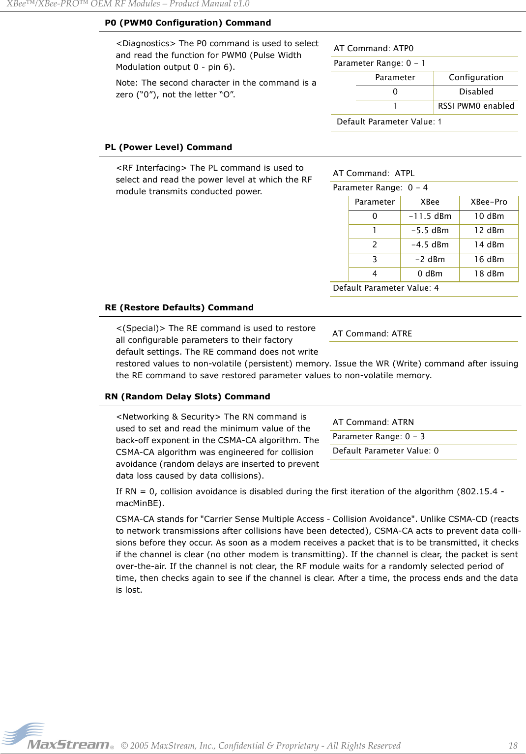
![XBee™/XBee‐PRO™OEMRFModules–ProductManualv1.0©2005MaxStream,Inc.,Confidential&Proprietary‐AllRightsReserved 153.3. Command DescriptionsCommand descriptions in this section are listed alphabetically. Command categories are desig-nated within "< >" symbols that follow each command title. XBee-PRO RF modules expect param-eter values in hexadecimal (designated by the "0x" prefix).BD (Interface Data Rate) Command<Serial Interfacing> The BD command is used to set and read the serial interface data rate (baud rate) used between the RF module and host. This parameter determines the rate at which serial data is sent to the RF module from the host. Mod-ified interface data rates do not take effect until the CN (Exit AT Command Mode) command is issued and the system returns the 'OK' response.When parameters 0-7 are sent to the RF module, the respective interface data rates are used (as shown in the table on the right).The RF data rate is not affected by the BD param-eter. If the interface data rate is set higher than the RF data rate, a flow control configuration may need to be implemented.Non-standard Interface Data Rates: When parameter values outside the range of standard baud rates are sent, the closest interface data rate represented by the number is stored in the BD register. For example, a rate of 19200 bps can be set by sending the following command line "ATBD4B00". NOTE: When using Max-Stream’s X-CTU Software, non-standard interface data rates can only be set and read using the X-CTU ‘Terminal’ tab. Non-standard rates are not accessible through the ‘Modem Configuration’ tab.When the BD command is sent with a non-standard interface data rate, the UART will adjust to accommodate the requested interface rate. In most cases, the clock resolution will cause the stored BD parameter to vary from the parameter that was sent (refer to the table below). Reading the BD command (send "ATBD" command without an associated parameter value) will return the value that was actually stored to the BD register.CC (Command Sequence Character) Command<AT Command Mode Options> The CC command is used to set and read the ASCII character used between guard times of the AT Command Mode Sequence (GT + CC + GT). This sequence enters the RF module into AT Command Mode so that data entering the modem from the host is recog-nized as commands instead of payload.Refer to the Command Mode section [p11] for more information regarding the AT Command Mode Sequence.Tab le3‐02. ParametersSentVer susParametersStoredBD Parameter Sent (HEX) Interface Data Rate (bps) BD Parameter Stored (HEX)0 1200 04 19,200 47 115,200 712C 300 12B1C200 115,200 1B207AT Command: ATBDParameter Range: 0 - 7 (standard rates)Parameter Configuration (bps)0 12001 24002 48003 96004 192005 384006 576007 115200Default Parameter Value:3AT Command: ATCCParameter Range: 0 - 0xFFDefault Parameter Value: 0x2B (ASCII “+”)Related Commands: GT (Guard Times)](https://usermanual.wiki/MaxStream/XBEE.USERS-MANUAL/User-Guide-585645-Page-15.png)
![XBee™/XBee‐PRO™OEMRFModules–ProductManualv1.0©2005MaxStream,Inc.,Confidential&Proprietary‐AllRightsReserved 16CH (Channel) Command<Networking & Security> The CH command is used to set and read the channel on which RF connections are made between RF modules. The channel is one of three network layers available to the RF module. The other layers are the PAN ID (ID command) and destination addresses (DL & DH commands).In order for RF modules to communicate with each other, the RF modules must share the same channel number. Different channels can be used to prevent RF modules in one network from listening to transmissions of another.The RF module uses channel numbers of the 802.15.4 standard. Center Frequency = 2.405 + (CH - 11d) * 5 MHz (d = decimal)Refer to the “Addressing Overview” section [p12] for more information.CN (Exit AT Command Mode) Command<AT Command Mode Options> The CN command is used to explicitly exit the RF module from AT Command Mode.CT (Command Mode Timeout) Command<AT Command Mode Options> The CT command is used to set and read the amount of inactive time that elapses before the RF module automati-cally exits from AT Command Mode and returns to Idle Mode.Use the CN (Exit AT Command Mode) command to exit AT Command Mode manually.DB (Received Signal Strength) Command<Diagnostics> The DB parameter is used to read the received signal strength (in dBm) of the last RF packet received. Reported values are accurate between -40 dBm and the RF module's receiver sensitivity.Absolute values are reported. For example: 0x58 = -88 dBm. If no packets have been received (since last reset, power cycle or sleep event), “0” will be reported.DH (Destination Address High) Command<Networking & Security> The DH command is used to set and read the upper 32 bits of the RF module's 64-bit destination address. When com-bined with the DL (Destination Address Low) parameter, it defines the destination address used for transmission.RF modules will only communicate with other RF modules having the same channel (CH parame-ter), PAN ID (ID parameter) and destination address (DH + DL parameters).To transmit using a 16-bit address, set the DL parameter to zero and the DH parameter less than 0xFFFF. 0x000000000000FFFF (DH concatenated to DL) is the broadcast address for the PAN.Refer to the “Addressing Overview” section [p12] for more information.AT Command: ATCHParameter Range: 0x0B - 0x1A (XBee) 0x0C - 0x18 (XBee-PRO)Default Parameter Value: 0x0C (12 decimal)Related Commands: ID (PAN ID), DL (Destination Address Low, DH (Destination Address High)AT Command: ATCNAT Command: ATCTParameter Range: 2 - 0xFFFF [x 100 milliseconds]Default Parameter Value: 0x64 (100 decimal, which equals 10 decimal seconds)Number of bytes returned: 2Related Command: CN (Exit AT Command Mode)AT Command: ATDBParameter Range: 0 - 0x64 [read-only]AT Command: ATDHParameter Range: 0 - 0xFFFFFFFFDefault Parameter Value: 0Related Commands: DL (Destination Address Low), CH (Channel), ID (PAN VID), MY (Source Address)](https://usermanual.wiki/MaxStream/XBEE.USERS-MANUAL/User-Guide-585645-Page-16.png)
![XBee™/XBee‐PRO™OEMRFModules–ProductManualv1.0©2005MaxStream,Inc.,Confidential&Proprietary‐AllRightsReserved 17DL (Destination Address Low) Command<Networking & Security> The DL command is used to set and read the lower 32 bits of the RF module's 64-bit destination address. When com-bined with the DH (Destination Address High) parameter, it defines the destination address used for transmission.RF modules will only communicate with other RF modules having the same channel (CH parameter), PAN ID (ID parameter) and destination address (DH + DL parameters).To transmit using a 16-bit address, set the DL parameter to zero and the DH parameter less than 0xFFFF. 0x000000000000FFFF (DH concatenated to DL) is the broadcast address for the PAN.Refer to the “Addressing Overview” section [p12] for more information.GT (Guard Times) Command<AT Command Mode Options> GT Command is used to set the DI (data in from host) time-of-silence that surrounds the AT command sequence character (CC Command) of the AT Command Mode sequence (GT + CC + GT). The DI time-of-silence is used to prevent inad-vertent entrance into AT Command Mode.Refer to the Command Mode section [p11] for more information regarding the AT Command Mode Sequence.ID (Pan ID) Command<Networking & Security> The ID command is used to set and read the PAN (Personal Area Net-work) ID of the RF module. Only RF modules with matching PAN IDs can communicate with each other. RF modems with non-matching PAN IDs will not receive unintended data transmission.Setting ID to 0xFFFF indicates a global message for all PANs.Refer to the “Addressing Overview” section [p12] for more information.MY (16-bit Source Address) Command<Networking & Security> The MY command is used to set and read the 16-bit source address of the RF module.By setting MY to 0xFFFF, the reception of RF packets having a 16-bit address is disabled. The 64-bit address is the module serial number and is always enabled.Refer to the “Addressing Overview” section [p12] for more information.AT Command: ATDLParameter Range: 0 - 0xFFFFFFFFDefault Parameter Value: 0Related Commands: DH (Destination Address High), CH (Channel), ID (PAN VID), MY (Source Address)AT Command: ATGTParameter Range: 0x02 - 0xFFFF [x 1 millisecond]Default Parameter Value: 0x3E8Related Commands: CC (Command Sequence Character)AT Command: ATIDParameter Range: 0 - 0xFFFFDefault Parameter Value:0x3332(13106 decimal)AT Command: ATMYParameter Range: 0 - 0xFFFFDefault Parameter Value: 0Related Commands: DH (Destination Address High), DL (Destination Address Low), CH (Channel), ID (PAN ID)](https://usermanual.wiki/MaxStream/XBEE.USERS-MANUAL/User-Guide-585645-Page-17.png)
![XBee™/XBee‐PRO™OEMRFModules–ProductManualv1.0©2005MaxStream,Inc.,Confidential&Proprietary‐AllRightsReserved 19RO (Packetization Timeout) Command<Serial Interfacing> The RO command is used to set and read the number of character times of inter-character delay required before transmis-sion. RF transmission commences when data is detected in the DI (data in from host) buffer and RO character times of silence are detected on the UART receive lines (after receiving at least 1 byte).(RF transmission will also commence when 100 bytes (maximum packet size) are received in the DI buffer.)Set the RO parameter to '0' to transmit characters as they arrive instead of buffering them into one RF packet.RP (RSSI PWM Timer) Command<Diagnostics> The RP command is used to enable PWM (Pulse Width Modulation) output on the RF module. The output is calibrated to show the level a received RF signal is above the sensi-tivity level of the RF module. The PWM pulses vary from zero to 95 percent. Zero to twenty-nine percent means the received RF signal is at or below the published sensitivity level of the RF mod-ule. The following table shows levels above sensitivity and PWM values.The total period of the PWM output is 8.32 ms. Because there are 40 steps in the PWM output, the minimum step size is 0.208 ms.*PWM%=(295+(17.5*dBmabovesensitivity))/10.24A non-zero value defines the time that the PWM output will be active with the RSSI value of the last received RF packet. After the set time when no RF packets are received, the PWM output will be set low (0 percent PWM) until another RF packet is received. The PWM output will also be set low at power-up until the first RF packet is received. A parameter value of 0xFF permanently enables the PWM output and it will always reflect the value of the last received RF packet.SH (Serial Number High) Command<Diagnostics> The SH command is used to read the high 32 bits of the RF module's unique IEEE 64-bit address.The RF module serial number is set at the factory and is read-only.SL (Serial Number Low) Command<Diagnostics> The SL command is used to read the low 32 bits of the RF module's unique IEEE 64-bit address.The RF module serial number is set at the factory and is read-only.Tab le3‐03. PWMPercentagesdB above Sensitivity PWM percentage*(high period / total period)10 46.0%20 63.0%30 80.1%AT Command: ATROParameter Range: 0 - 0xFF[x character times]Default Parameter Value: 3AT Command: ATRPParameter Range: 0 - 0xFF[x 100 milliseconds]Default Parameter Value: 0x28 (40 decimal)AT Command: ATSHParameter Range: 0 - 0xFFFFFFFF [read-only]Related Commands: SL (Serial Number Low), MY (Source Address)AT Command: ATSLParameter Range: 0 - 0xFFFFFFFF [read-only]Related Commands: SH (Serial Number High), MY (Source Address)](https://usermanual.wiki/MaxStream/XBEE.USERS-MANUAL/User-Guide-585645-Page-19.png)
![XBee™/XBee‐PRO™OEMRFModules–ProductManualv1.0©2005MaxStream,Inc.,Confidential&Proprietary‐AllRightsReserved 20SM (Sleep Mode) Command<Sleep Mode (Low Power)> The SM command is used to set and read RF module Sleep Mode set-tings. By default, Sleep Modes are disabled (SM = 0) and the RF module remains in Idle/Receive Mode. When in this state, the RF module is con-stantly ready to respond to either serial or RF activity.SP (Cyclic Sleep Period) Command<Sleep Mode (Low Power)> The SP command is used to set and read the duration of time in which a remote RF module sleeps. After the cyclic sleep period is over, the RF module wakes and checks for data. If data is not present, the RF module goes back to sleep. The maximum sleep period is 268 seconds (SP = 0x68B0).The SP parameter is only valid if the RF module is configured to operate in Cyclic Sleep (SM = 4-6).ST (Time before Sleep) Command<Sleep Mode (Low Power)> The ST command is used to set and read the period of time that the RF module remains inactive (no transmitting or receiving) before entering into Sleep Mode. For example, if the ST parameter is set to its default value of 0x1388 (5000 decimal), the RF module will enter into Sleep mode after 5 seconds of inactivity. This command can only be used if Cyclic Sleep settings have been selected using SM (Sleep Mode) Command (SM = 4-6).VR (Firmware Version) Command<Diagnostics> The VR command is used to read which firmware version is stored in the RF mod-ule.WR (Write) Command<(Special)> The WR command is used to write configurable parameters to the RF module's non-volatile memory (Parameter values remain in RF module's memory until overwritten by subsequent use of the WR Command). If changes are made without writing them to non-volatile memory, the RF module reverts back to previously saved parameters the next time the RF module is powered-on.AT Command: ATSMParameter Range: 0 - 6 Parameter Configuration0 Disabled1Pin Hibernate2Pin Doze3(reserved)4 Cyclic Sleep Remote5Cyclic Sleep Remote(with Pin Wake-up)6Cyclic Sleep CoordinatorDefault Parameter Value: 0Related Commands: SP (Cyclic Sleep Period), ST (Time before Sleep)AT Command: ATSPParameter Range: 1 - 0x68B0 [x 10 milliseconds]Default Parameter Value:0x64 (100 decimal)Related Commands: SM (Sleep Mode), ST (Time before Sleep)AT Command: ATSTParameter Range: 1 - 0xFFFF [x 1 millisecond]Default Parameter Value:0x1388 (5000 decimal)Related Commands: SM (Sleep Mode), SP (Cyclic Sleep Period)AT Command: ATVRParameter Range: 1 - 0xFFFF [read only]AT Command: ATWR](https://usermanual.wiki/MaxStream/XBEE.USERS-MANUAL/User-Guide-585645-Page-20.png)
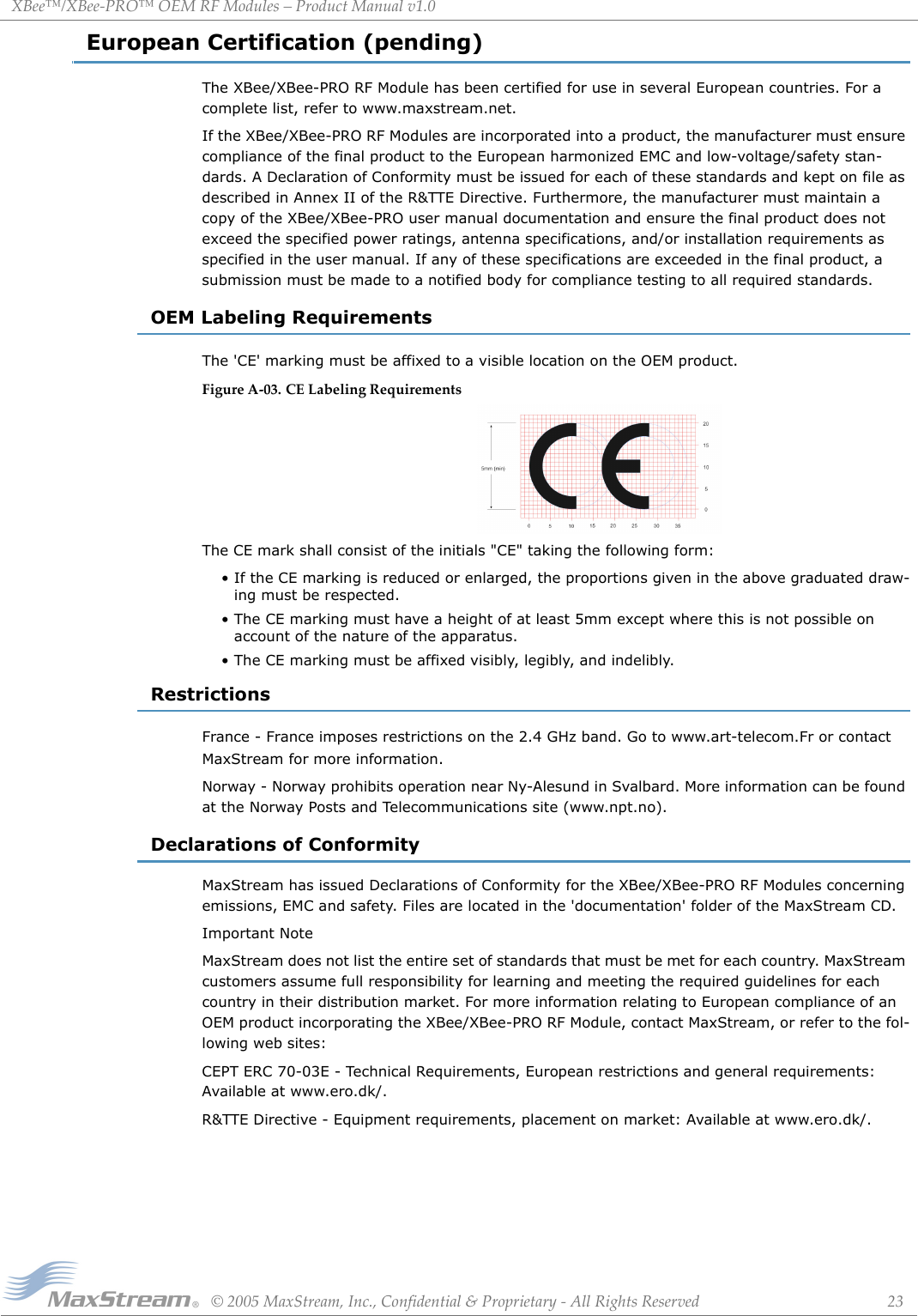
![XBee™/XBee‐PRO™OEMRFModules–ProductManualv1.0©2005MaxStream,Inc.,Confidential&Proprietary‐AllRightsReserved 21AppendixA:AgencyCertificationsFCC Certification (pending)The XBee/XBee-PRO RF Module complies with Part 15 of the FCC rules and regulations. Compli-ance with the labeling requirements, FCC notices and antenna usage guidelines is required.To fulfill FCC Certification requirements, the OEM must comply with the following regulations:OEM Labeling RequirementsFigureA‐01. RequiredFCCLabelforOEMproductscontainingtheXBee/XBee‐PRORFModuleFCC NoticesIMPORTANT: The XBee/XBee-PRO OEM RF Module has been certified by the FCC for use with other products without any further certification (as per FCC section 2.1091). Changes or modifica-tions not expressly approved by MaxStream could void the user's authority to operate the equip-ment.IMPORTANT: OEMs must test final product to comply with unintentional radiators (FCC section 15.107 & 15.109) before declaring compliance of their final product to Part 15 of the FCC Rules.IMPORTANT: The RF module has been certified for remote and base radio applications. If the module will be used for portable applications, the device must undergo SAR testing.This equipment has been tested and found to comply with the limits for a Class B digital device, pursuant to Part 15 of the FCC Rules. These limits are designed to provide reasonable protection against harmful interference in a residential installation. This equipment generates, uses and can radiate radio frequency energy and, if not installed and used in accordance with the instructions, may cause harmful interference to radio communications. However, there is no guarantee that interference will not occur in a particular installation. If this equipment does cause harmful interference to radio or television reception, which can be determined by turning the equipment off and on, the user is encouraged to try to correct the inter-ference by one or more of the following measures: Re-orient or relocate the receiving antenna, Increase the separation between the equipment and receiver, Connect equipment and receiver to outlets on different circuits, or Consult the dealer or an experienced radio/TV technician for help.1. The system integrator must ensure that the text on the external label provided with this device is placed on the outside of the final product [Figure A-01].2. The XBee/XBee-PRO RF Module may be used only with approved antennas that have been tested with this modem.WARNING: The Original Equipment Manufacturer (OEM) must ensure that FCC labeling requirements are met. This includes a clearly visible label on the outside of the final product enclosure that displays the contents shown in the figure below.Contains FCC ID: pendingThe enclosed device complies with Part 15 of the FCC Rules. Operation is subject to the following two conditions: (1) this device may not cause harmful interference and (2) this device must accept any inter-ference received, including interference that may cause undesired operation.](https://usermanual.wiki/MaxStream/XBEE.USERS-MANUAL/User-Guide-585645-Page-21.png)
![XBee™/XBee‐PRO™OEMRFModules–ProductManualv1.0©2005MaxStream,Inc.,Confidential&Proprietary‐AllRightsReserved 22FCC-Approved Antennas (2.4 GHz)The XBee/XBee-Pro OEM RF Module can be installed utilizing antennas and cables constructed with standard connectors (Type-N, SMA, TNC, etc.) if the installation is performed professionally and according to FCC guidelines. For installations not performed by a professional, non-standard con-nectors (RPSMA, RPTNC, etc.) must be used.The modules are pre-FCC approved for use in fixed base station and mobile applications [refer to table below]. As long as the antenna is mounted at least 20 cm (8 in) from nearby persons, the application is considered a mobile application. Antennas not listed in the table must be tested to comply with FCC Section 15.203 (unique antenna connectors) and Section 15.247 (emissions).*AntennascanbeapprovedforportableapplicationsifintegratorgainsapprovalthroughSARtesting.Iftheantennawillbemountedcloserthan20cmtonearbypersons,thentheapplicationisconsideredʺportableʺandrequiresanadditionaltestperformedonthefinalproduct.ThistestiscalledtheSpecificAbsorptionRate(SAR)testingandmeasurestheemissionsfromthemoduleandhowtheyaffecttheperson.RF ExposureThe preceding statement must be included as a CAUTION statement in manuals for OEM products to alert users on FCC RF Exposure compliance.Tab leA‐02. AntennasapprovedforusewiththeXBee/XBee‐PROOEMRFModules(all2.4GHz)Part Number Type (Description) Gain Application Min. SeparationA24-HABMM-PSI Dipole (Half-wave bulkhead mount articulated MMCX w/ pigtail) 2.1 dBi Fixed/Mobile* 20 cmA24-HBMM-PSI Dipole (Half-wave bulkhead mount MMCX w/ pigtail) 2.1 dBi Fixed/Mobile* 20 cmA24-HABSM Dipole (Articulated RPSMA) 2.1 dBi Fixed/Mobile* 20 cmA24-QBMM-PSI Monopole (Quarter-wave bulkhead mount MMCX w/pigtail) 1.9 dBi Fixed/Mobile* 20 cmA24-QABMM-PSI Monopole (Quarter-wave bulkhead mount articulated MMCX w/pigtail) 1.9 dBi Fixed/Mobile* 20 cmA24-QI Monopole (Integrated whip) 1.9 dBi Fixed/Mobile* 20 cmA24-C1 Surface Mount -1.5 dBi Fixed/Mobile* 20 cmA24-Y4NF Yagi (4-element) 6.0 dBi Fixed* 2 mA24-Y6NF Yagi (6-element) 8.8 dBi Fixed* 2 mA24-Y7NF Yagi (7-element) 9.0 dBi Fixed* 2 mA24-Y9NF Yagi (9-element) 10.0 dBi Fixed* 2 mA24-Y10NF Yagi (10-element) 11.0 dBi Fixed* 2 mA24-Y12NF Yagi (12-element) 12.0 dBi Fixed* 2 mA24-Y13NF Yagi (13-element) 12.0 dBi Fixed* 2 mA24-Y15NF Yagi (15-element) 12.5 dBi Fixed* 2 mA24-Y16NF Yagi (16-element) 13.5 dBi Fixed* 2 mA24-Y16RM Yagi (16-element, RPSMA connector) 13.5 dBi Fixed* 2 mA24-Y18NF Yagi (18-element) 15.0 dBi Fixed* 2 mA24-F2NF Omni-directional (Fiberglass base station) 2.1 dBi Fixed/Mobile* 20 cmA24-F3NF Omni-directional (Fiberglass base station) 3.0 dBi Fixed/Mobile* 20 cmA24-F5NF Omni-directional (Fiberglass base station) 5.0 dBi Fixed/Mobile* 20 cmA24-F8NF Omni-directional (Fiberglass base station) 8.0 dBi Fixed* 2 mA24-F9NF Omni-directional (Fiberglass base station) 9.5 dBi Fixed* 2 mA24-F10NF Omni-directional (Fiberglass base station) 10.0 dBi Fixed* 2 mA24-F12NF Omni-directional (Fiberglass base station) 12.0 dBi Fixed* 2 mA24-F15NF Omni-directional (Fiberglass base station) 15.0 dBi Fixed* 2 mA24-W7NF Omni-directional (Base station) 7.2 dBi Fixed* 2 mA24-M7NF Omni-directional (Mag-mount base station) 7.2 dBi Fixed* 2 mA24-P8SF Flat Panel 8.5 dBi Fixed* 2 mA24-P8NF Flat Panel 8.5 dBi Fixed* 2 mA24-P13NF Flat Panel 13.0 dBi Fixed* 2 mA24-P14NF Flat Panel 14.0 dBi Fixed* 2 mA24-P15NF Flat Panel 15.0 dBi Fixed* 2 mA24-P16NF Flat Panel 16.0 dBi Fixed* 2 mA24-P19NF Flat Panel 19.0 dBi Fixed* 2 mWARNING: To satisfy FCC RF exposure requirements for mobile transmitting devices, a separation distance of 20 cm or more should be maintained between the antenna of this device and persons during device operation. To ensure compliance, operations at closer than this distance is not recommended.The antenna used for this transmitter must not be co-located in conjunction with any other antenna or transmitter.](https://usermanual.wiki/MaxStream/XBEE.USERS-MANUAL/User-Guide-585645-Page-22.png)

![XBee™/XBee‐PRO™OEMRFModules–ProductManualv1.0©2005MaxStream,Inc.,Confidential&Proprietary‐AllRightsReserved 31Contact MaxStreamFree and unlimited technical support is included with every MaxStream Radio Modem sold.For the best in wireless data solutions and support, please use the following resources:MaxStream office hours are 8:00 am - 5:00 pm [U.S. Mountain Standard Time]Documentation: www.maxstream.net/helpdesk/download.phpTechnical Support: Phone. (866) 765-9885 toll-free U.S.A. & Canada (801) 765-9885 WorldwideLive Chat. www.maxstream.net E-Mail. rf-xperts@maxstream.net](https://usermanual.wiki/MaxStream/XBEE.USERS-MANUAL/User-Guide-585645-Page-31.png)