Maxell ME-K01 RFID Reader/Writer Unit User Manual SoftwareManual
Hitachi Maxell, Ltd. RFID Reader/Writer Unit SoftwareManual
UserManual.wiki
>
Maxell
>
ME-K01 User Manual
>
SoftwareManual
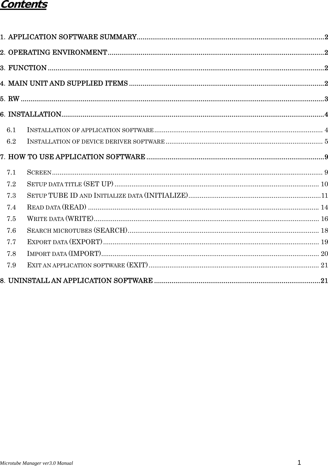
Contents
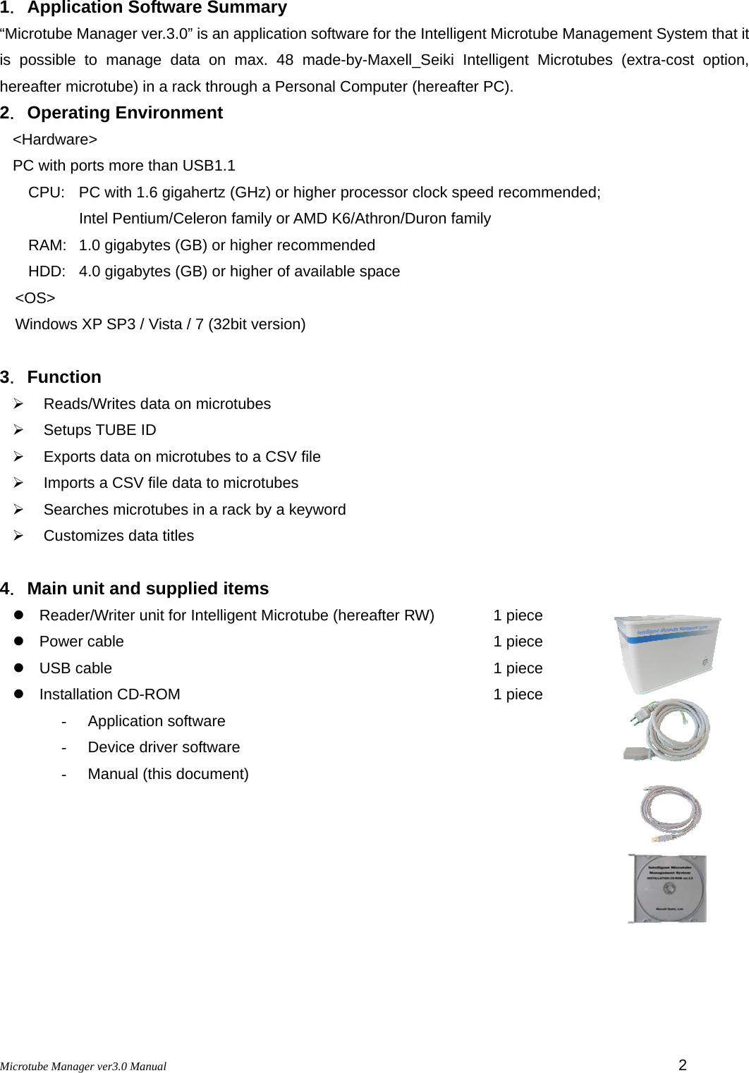
1.
HardwareManual
2.
SoftwareManual
SoftwareManual
Navigation menu
Upload a User Manual
Namespaces
Wiki Guide
HTML
PDF
Info
Views
User Manual
Discussion / Help
Navigation
![Microtube Manager ver3.0 Manual 4 6.Installation When installing “Microtube Manager ver.3.0” and device drivers of RW, follow these steps. * Please login as Administrator. * Images are Windows 7. Install an application software before connecting RW to PC. 6.1 Installation of application software 1. Set an installation CD-ROM on PC. 2. Double-click “setup.exe”. 3. When “Microsoft .NET Framework 4 Client Profile” is not installed on your PC, installer installs “Microsoft .NET Framework 4 Client Profile”. Read the terms of the pending License Agreement and them click [Accept]. * When “Microsoft .NET Framework 4 Client Profile” is installed on your PC, go to step 5. 4. Click [YES] because “User Account Control” is displayed. * Except Windows XP. * Windows may require a restart of the PC. In that case, restart and then double-click “setup.exe” again. 5. Click [Next] because “MicroTube Setup Wizard” is displayed. 6. When installing to a different folder, enter it or click [Browse]. Select whether install this application software for yourself or for anyone who uses the PC, and then click [Next].](https://usermanual.wiki/Maxell/ME-K01.SoftwareManual/User-Guide-1441568-Page-5.png)
![Microtube Manager ver3.0 Manual 5 7. Click [Next]. 8. Click [YES] because “User Account Control” is displayed. * Except Windows XP. 9. Click [Close]. Confirm that “Microtube Management.exe” icon is displayed on desktop. 6.2 Installation of device deriver software Firstly, Plug a power cable and a USB cable into RW. Next, plug a power cable into an outlet and then plug a USB cable into PC after turning front-mounted power button on. Install an application software before connecting RW to PC. Don’t launch an application software. Power on: Green light](https://usermanual.wiki/Maxell/ME-K01.SoftwareManual/User-Guide-1441568-Page-6.png)
![Microtube Manager ver3.0 Manual 6 < Windows Vista / 7 > 1. When RW is connected with PC with USB cable for the first time, the driver software is automatically installed. Perform the following steps after the message “Device driver software was not successfully installed” in the right image is displayed. PC cannot install the driver software automatically because RW controls 6 parts by USB hub. 2. Click in the following order: <Control Panel> -> <Hardware and Sound> -> <Device Manager> 3. RW is recognized as “Other devices”. Name: “RFID R/W ME-LM1M9S-A10” with “!” mark Quantity: 6 pcs 4. Right-click on “RFID R/W ME-LM1M9S-A10” and then select “Update Driver Software”. 5. Click “Browse my computer for driver software”. 6. Supply “Driver for WindowsVista_7” in the Installation CD-ROM and then click [Next].](https://usermanual.wiki/Maxell/ME-K01.SoftwareManual/User-Guide-1441568-Page-7.png)
![Microtube Manager ver3.0 Manual 7 7. “Windows Security” is displayed, but click “Install this driver software anyway”. 8. Click [Close]. 9. Repeat installation of driver software 6 times. 1) When completing installation of driver software, “TAG IC R/W unit” is displayed on Device Manager. 2) When opening “TAG IC R/W unit”, 6 “Coil-on-Chip RFID System” are displayed. “?” mark is displayed, but RW works normally. * Part of Windows Vista PC and Windows 7 PC may not work normally. 3) When launching application software in a state of not completing installation of driver software correctly, error message is displayed. Make sure the driver software is correctly installed in 6 RW.](https://usermanual.wiki/Maxell/ME-K01.SoftwareManual/User-Guide-1441568-Page-8.png)
![Microtube Manager ver3.0 Manual 8 < Windows XP > 1. When RW is connected with PC with USB cable for the first time, “Found New Hardware Wizard” is displayed. Select “No, not this time” and then click [Next]. 2. Select “Install the software automatically (Recommended)” and then click [Next]. 3. Click [Finish]. 4. Repeat above steps 6 times. 1) “Found New Hardware Wizard” is displayed 6 times. Repeat above steps 6 times. 2) When launching application software in a state of not completing installation of driver software correctly, error message is displayed. Make sure the driver software is correctly installed in 6 RW.](https://usermanual.wiki/Maxell/ME-K01.SoftwareManual/User-Guide-1441568-Page-9.png)
![Microtube Manager ver3.0 Manual 11 7.3 Setup TUBE ID and Initialize data (INITIALIZE) Use this function when managing serial numbers by yourself. Able to select operation from the following 2 patterns. - ALL DATA(A) : TUBE ID setting + Data initialization - TUBE ID(T) : TUBE ID setting < TUBE ID(T) > 1. Click EDIT(E) from the menu and then select TUBE ID(T) from INITIALIZE(I). 2. Input the first serial number on “Initial Tube ID No.(Microtube A1)” and then click [OK]. Serial number of “End Tube ID No.(Microtube F8)” that adds 47 to the first serial number is set automatically. EX) Microtube A1: 100 -> Micortube F8: 147 1) TUBE ID is serial numbers. Order is as follows: A1, A2, ->, A8, B1, B2, -> F7, F8 2) Input a serial number by the decimal number. 3) Writable serial number range on Microtube A1: 0 - 99999952 When an out-of-serial number is input, the error message is displayed. 3. Click [OK].](https://usermanual.wiki/Maxell/ME-K01.SoftwareManual/User-Guide-1441568-Page-12.png)
![Microtube Manager ver3.0 Manual 12 4. Confirm that a rack is set on the antenna of RW. When clicking [OK], RW writes TUBE ID. Able to confirm data because RW reads data automatically after completing INITIALIZE. < ALL DATA(A) > 1. Click EDIT(E) from the menu and then select ALL DATA(A) from INITIALIZE(I). 2. Input the first serial number on “Initial Tube ID No.(Microtube A1)” and then click [OK]. Serial number of “End Tube ID No.(Microtube F8)” that adds 47 to the first serial number is set automatically. EX) Microtube A1: 100 -> Micortube F8: 147 1) TUBE ID is serial numbers. Order is as follows: A1, A2, ->, A8, B1, B2, -> F7, F8 2) Input a serial number by the decimal number. 3) Writable serial number range on Microtube A1: 0 - 99999952 When an out-of-serial number is input, the error message is displayed.](https://usermanual.wiki/Maxell/ME-K01.SoftwareManual/User-Guide-1441568-Page-13.png)
![Microtube Manager ver3.0 Manual 13 3. Click [OK]. 4. Confirm that a rack is set on the antenna of RW. When clicking [OK], RW writes TUBE ID and initializes data. Able to confirm data because RW reads data automatically after completing INITIALIZE. Only TUBE ID and LASER ID are displayed on “DATA”.](https://usermanual.wiki/Maxell/ME-K01.SoftwareManual/User-Guide-1441568-Page-14.png)
![Microtube Manager ver3.0 Manual 14 7.4 Read data (READ) When reading Intelligent Microtube data for the first time, the following window is displayed. 1. Reads data by clicking [READ]. * As for the following images, data is written on Intelligent Microtube. When failing in reading Intelligent Microtube data, MICROTUBE DETECTED mark “ “ is not displayed on failed Intelligent Microtube. Please confirm that Intelligent Microtubes are set in a rack exactly and click [READ] again. Failure Success * Only TUBE ID and LASER ID are displayed.](https://usermanual.wiki/Maxell/ME-K01.SoftwareManual/User-Guide-1441568-Page-15.png)
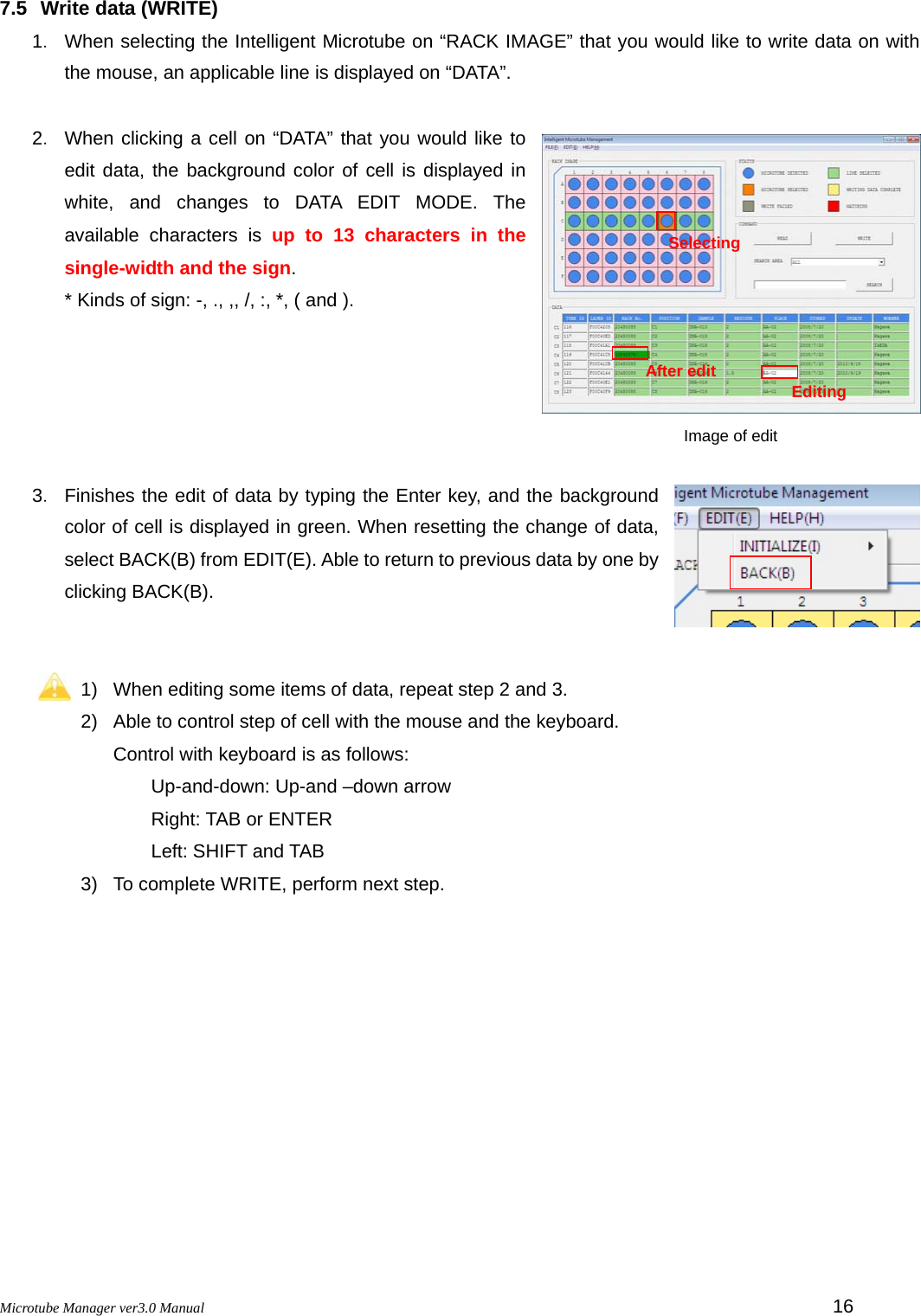
![Microtube Manager ver3.0 Manual 17 4. When clicking [WRITE], RW writes data on the Intelligent Microtubes. When completing WRITE correctly, the background color on “RACK IMAGE” of Intelligent Microtube that data has been written is displayed in yellow. When failing in writing data, the background color of Intelligent Microtube is displayed in gray. In that case, check whether a rack is correctly set on the antenna of RW or the Intelligent Microtube is correctly put into a rack and then click [WRITE] again. 1) When confirming written data, click [READ] again. 2) Data is written in each line. 3) Able to setup titles of “DATA” with SET UP(S). Regarding the details of SET UP(S), please refer to “7.2 Setup data title (SET UP)”. 4) Unable to change LASER ID. Failure Success](https://usermanual.wiki/Maxell/ME-K01.SoftwareManual/User-Guide-1441568-Page-18.png)
![Microtube Manager ver3.0 Manual 18 7.6 Search microtubes (SEARCH) Able to search the positions of microtube in a rack by selecting a title from ≪SEARCH AREA≫. 1. Select a title from ≪SEARCH AREA≫. Edited titles are displayed. “ALL” searches a keyword from all titles. 2. Input a keyword into a search box. EX) When inputting “DNA” as a keyword, both of DNA-1 and DNA-2 match “DNA” as the result. 3. When clicking [SEARCH], application software searches a keyword and displays the result. 4. When data matches, the background color of microtube in “RACK IMAGE” is displayed in red. Match Unmatch](https://usermanual.wiki/Maxell/ME-K01.SoftwareManual/User-Guide-1441568-Page-19.png)
![Microtube Manager ver3.0 Manual 19 7.7 Export data (EXPORT) Exports all microtube data in a rack as a CSV file. 1. Click FILE(F) from the menu and then select EXPORT(E). 2. Supply a destination folder, input a file name and then click [Save]. 3. Confirm that a rack is set on the antenna of RW. When clicking [OK], RW reads data and exports the data. Able to open the data with software such as Microsoft Excel or Notepad. EX) CSV file image when opening data with Excel.](https://usermanual.wiki/Maxell/ME-K01.SoftwareManual/User-Guide-1441568-Page-20.png)
![Microtube Manager ver3.0 Manual 20 7.8 Import data (IMPORT) Able to write data of a prepared CSV file in one pass. 1. Click FILE(F) from the menu and then select IMPORT(I). 2. Supply a data file and then click [Open]. 3. Click [OK]. 4. Confirm that a rack is set on the antenna of RW. When clicking [OK], RW imports data. 1) Impotable data must follow same data format as exported CSV file . 2) We recommend using a file that is saved in “7.7 Export data (EXPORT)” as a CSV data format. 3) Don’t delete the title written in the first line in CSV data format. Moreover, even if titles are changed, these are not updated with imported data. Regarding the change of title, please refer to “7.2 Setup data title (SET UP)”.](https://usermanual.wiki/Maxell/ME-K01.SoftwareManual/User-Guide-1441568-Page-21.png)
![Microtube Manager ver3.0 Manual 21 7.9 Exit an application software (EXIT) 1. Click FILE(F) from the menu and then select EXIT(C) or then click × button on screen. 2. Click [Yes]. 8.Uninstall an application software < Windows Vista / 7 > 1. Click in the following order. <Control Panel> -> <Uninstall a program> 2. Select “MicroTube” from the list, right-click on it and then click [Uninstall]. < Windows XP > 1. Double-click “Add or Remove Programs” in “Control Panel”. 2. Select “MicroTube” from the list and then click [Remove]. * Windows, Excel and Notepad are trademarks or registered trademarks of Microsoft Corporation in the United States and/or other countries. For inquiries about Microtube Manager ver3.0, please contact authorized distributor for assistance.](https://usermanual.wiki/Maxell/ME-K01.SoftwareManual/User-Guide-1441568-Page-22.png)