Maxell ME-M21 RFID Reader/Writer Module User Manual
Hitachi Maxell, Ltd. RFID Reader/Writer Module Users Manual
Maxell >
Contents
- 1. User Manual
- 2. Installation Manual
User Manual

Manual
Reader/Writer Module
ME-MA21 (UART I/F)
ME-MR21 (RS232C I/F)
1. External Appearance
2. Application
3. Product Outline
4. Specifications
5. Receiving property parameters
6. Notices before use
7. Notes in handling
8. Notes in operating
FCC WARNING
Coil-on-Chip RFID ME-MA21/MR21
MAXELL SEIKI CONFIDENTIAL
1
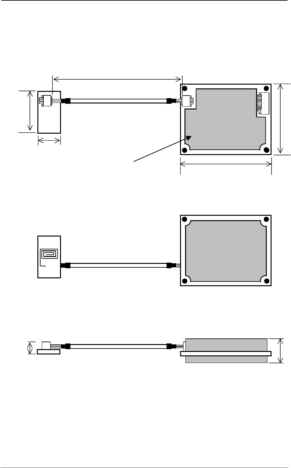
1 External Appearance
Antenna cable
Reader/Writer module
ME-MA21
ME-MR21
Antenna
ME-CK21
18.8±0.5mm
34.6±0.5mm
MA21 100±20mm
MR21 150±20mm
50.0±0.5mm
65.0±0.5mm
Where model name
label is affixed.
14.2mm(max)
7.0mm(max)

ME-MA21/MR21 Coil-on-Chip RFID
2 Application
These specifications are applicable to the reader/writer modules for RFID: ME-MA21 and ME-MR21
that are delivered by Maxell Seiki, Ltd. (referred to as Maxell hereafter), to SEGA Corporation (referred
to as SEGA hereafter) by way of Kaga Devices Co., Ltd.
3 Product outline
3.1 Outline of ME-MA21 (UART I/F)
The ME-MA21 is used in a reader/writer module for RFID that performs data communication with a
host system using UART I/F (CMOS level I/F), by connecting the device to equipment prepared by
SEGA. Applicable RFID chips are ME-Y2000 series products (1Kbyte/2Kbyte/4Kbyte), which perform
data processing by radio communication with RFID chip incorporated in a card.
The following provides circuit block diagram of the ME-MA21 module:
3.2 Outline of ME-MR21 (RS232C I/F)
The ME-MR21 is used in a reader/writer module for RFID that performs data communication with a
host system using RS232C I/F (RS232C level I/F), by connecting the device to equipment prepared by
SEGA. Applicable RFID chips are ME-Y2000 series products (1Kbyte/2Kbyte/4Kbyte), which perform
data processing by radio communication with RFID chip incorporated in a card.
The following provides circuit block diagram of the ME-MR21 module:
2 MAXELL SEIKI CONFIDENTIAL

Coil-on-Chip RFID ME-MA21/MR21
MAXELL SEIKI CONFIDENTIAL 3
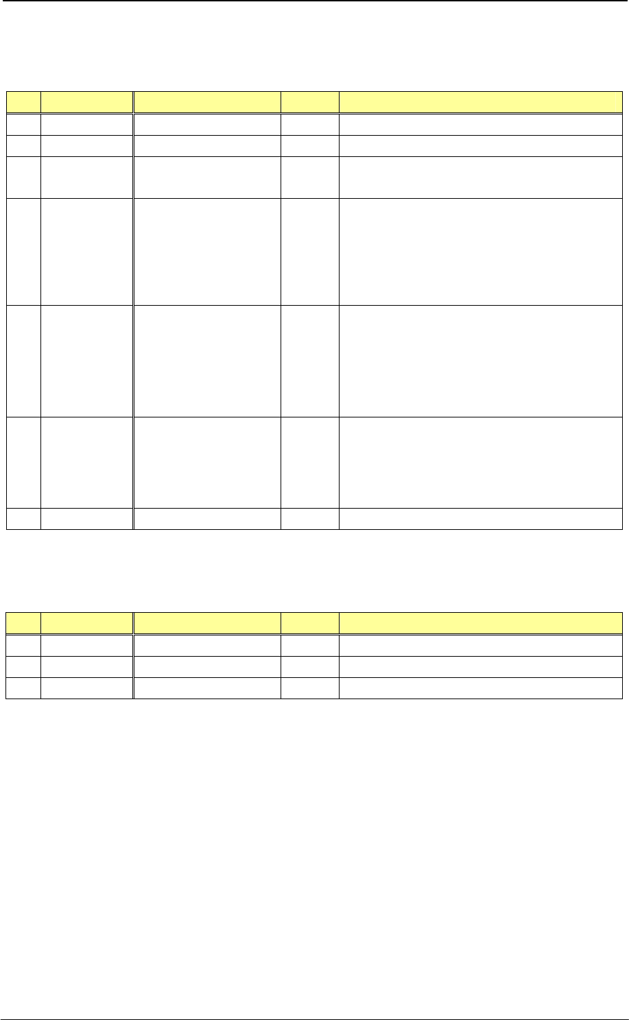
4 Specifications
4.1 Environmental performances
No Item Specifications
1 Operating temperature range 0 ~ 50°C
2 Operating humidity range 20 ~ 80%RH (No condensation)
3 Storage temperature range -10 ~ 60°C
4 Storage humidity range 20 ~ 80%RH (No condensation)
4.2 Physical specifications
・Reader/Writer module
・Antenna module
No Item Specifications
1 Outer dimensions 50.0mm (D) x 65.0mm (W) x 14.2mm (H: max.)
2 Material of board Glass epoxy FR-4
3 Weight Approximately 32g
No Item Specifications
1 Outer dimensions 18.8mm (D) x 34.6mm (W) x 7.0mm (H: max.)
2 Material of board Glass epoxy FR-4
3 Weight Approximately 2g

ME-MA21/MR21 Coil-on-Chip RFID
4.3 Electrical performance
・MA21
Item Specifications
Power supply voltage 4.75~5.25 V
Current consumption
1) Max. 700mA
Operating condition: Primary condition is turning-on carrier.
2) Max. 110mA
Idle 1 and Idle 2 conditions: Primary condition is turning-off carrier.
Carrier frequency 13.56MHz±15ppm or lower
Data rate 212kbps
Communication
quality*
-Communicating distance: 0.7 to 2.2mm
-Allowable transverse displacement (width direction): ±1.0mm/vertcal
displacement (length direction): ±2.0mm (from antenna board to
antenna side of RFID chip on board)
-Communication of only one card
1) When communicating, adjust an amplifier gain at an optimum level on
the host system.
2) Do not install any parts of metal or magnetic material around the
antenna.
Carrier on/off ratio Ratio of on status: 50% or lower
Item Specifications
Power supply voltage 4.75~5.25 V
Current consumption
1) Max. 900mA
Operating condition: Primary condition is turning-on carrier.
2) Max. 110mA
Idle 1 and Idle 2 conditions: Primary condition is turning-off carrier
Carrier frequency 13.56MHz±15ppm or lower
Data rate 212kbps
Communication quality*
-Communicating distance: 1.0 to 2.2mm (communicating using one card)
1.0 to 1.6mm (communicating using two cards)
(from antenna board to antenna side of RFID chip on board)
-Allowable transverse displacement (width direction): ±1.0mm/vertcal
displacement (length direction): ±2.0mm
1) When communicating, adjust an amplifier gain at an optimum level on
the host system.
2) Do not install any parts of metal or magnetic material around the
antenna.
Carrier on/off ratio Ratio of on status: 50% or lower
・MR21
* Values in the table above are provided for reference purpose only. The values fluctuate according
to actual system environments. Perform evaluation on an actual system environment, and adjust
communication distance, gain settings, and transverse displacement for secure communication.
The “communication distance” above refers to a distance between an antenna-coil surface of RFID
chip and a R/W antenna coil. A distance between an RFID chip package surface and a R/W
antenna coil is shorter than the values above as much as a thickness of package.
4 MAXELL SEIKI CONFIDENTIAL
Coil-on-Chip RFID ME-MA21/MR21
MAXELL SEIKI CONFIDENTIAL 5
4.4 Interface specifications
4.4.1 CN101 connector pin alignment (host)
Pin Pin name Function Direction Remarks
1 GND GND(0V) - Ground
2 TXD Data output Output Sending data signal (output)
3 RXD Data input Input Receiving data signal (input)
(Connected to Vcc on board)
4 /DETECT Presence/absence of
chip Input
RFID chip presence/absence signal
Present: /DETECT=0
Absent: /DETECT=1
/DETECT=1 is applicable when “not used.”
(Pull-up with 1kΩ on board)
5 /ANTPWR Antenna power Input
Antenna power supply control signal
ON: /ANTPWR=0
OFF: /ANTPWR=1
Fixed to /ANTPWR=0 when “not used.”
(Pull-up with 1kΩ on board)
6 /RESET Reset signal Input
System reset signal
Reset: /RESET=0
Other than Reset: /RESET= open
/RESET is opened for “not used.”
7 VCC +5V power supply -
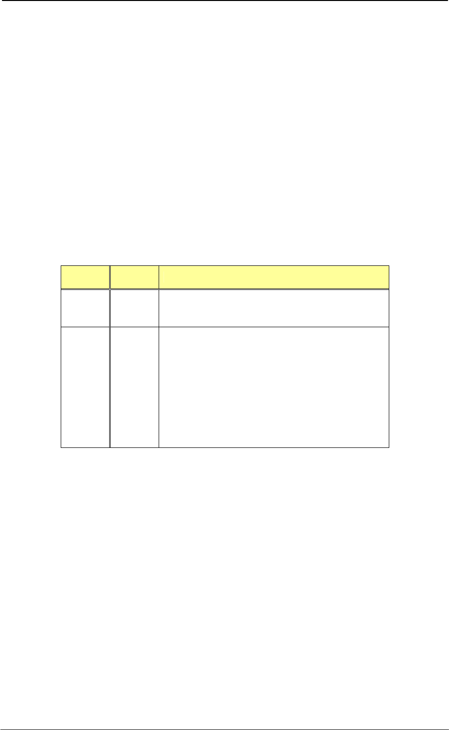
4.4.2 CN102 connector pin alignment (antenna)
Pin Pin name Function Direction Remarks
1 VANT Antenna power supply Output Core wire
2 GND GND - Shielded wire side
SIGNAL Analog signal Input Core wire

ME-MA21/MR21 Coil-on-Chip RFID
4.4.3 RXD/TXD communication specifications
Item Specifications
Communication rate
(real rate *1)
19,200 bps(18,750 bps)*2
38,400 bps(37,500 bps)
Communication mode RS232C half duplex
Synchronous mode Asynchronous
Flow control None
Number of start bits 1bit
Number of data bits 8bit
Number of stop bits 1bit
Number of parity bits bit/even
*1: The controller installed on this module uses a 6MHz oscillator. Because a communication
rate is generated by frequency division of the oscillator, actual rates of this module are
values in parentheses.
*2: A communication rate upon turning on the power (system resetting) is 19,200bps.
6 MAXELL SEIKI CONFIDENTIAL
Coil-on-Chip RFID ME-MA21/MR21
MAXELL SEIKI CONFIDENTIAL 7
5 Receiving property parameters
This setting is very important for stable reading and writing processings. Optimum receiving property
parameter values vary depending on communication characteristics of individual RFID chips and
positional relationship between the R/W antenna and the RFID chip. When communicating with
another RFID chip or after re-positioning the components (including removing and inserting a card), be
sure to optimize the receiving property parameters to agree with the receiving property of the RFID
chip.
Parameters to be optimized are slice level and gain. Switching of gain only also can optimize the
characteristics to some degree. To optimize the system more fitting to the using environments,
optimize the parameters in combination with a slice level.
Specify a comparator slice level using higher-order bits b7 to b4 (4 bits) of the receiving property
parameter. Also, specify an amplifier gain using lower-order bits b 3 to b0 (4 bits) of the parameter. The
following provides receiving property parameter setting registers and parameter values.
bit Reset
values Function
7 ~ 4 0
Slice level selecting bit
D: Low
E: High
3 ~ 0 0
Receiving gain
selecting bit
0: 14dB
1: 16dB
2: 18dB
3: 20dB
4: 22dB
5: 24dB
6: 26dB
7: 28dB
8: 30dB
9: 32dB
A: 34dB
B: 36dB
C: 38dB
D: 40dB
E: 42dB
F: 44dB
- Example of adjusting receiving property parameters
Find a gain setting that causes the least communication errors in product development and evaluation
stage, and set the value as default. In addition, provide software processing that automatically
fine-tunes the gain values upward and downward.
In consideration of operating conditions (power supply voltages and ambient temperatures), variation
of communicating distance, and variation of communicating performances of RFID chip, tuning the
gain in 1-LSB steps upward and downward is recommended.
For details, refer to the application notes.
Example: Setting values in lower 8 bits of receiving property parameter setting register:
Default “EA”→EB→E9→EC→E8→ED→E7→EE→E6→EF→E5 (→Return to default)
(Repeat several retries at each gain level.)

ME-MA21/MR21 Coil-on-Chip RFID
6 Notices before use
・ R The R/W module may not comply with the Electro Magnetic Interference (EMI) Standards by
itself.
Provide appropriate EMI measures on a system according to customer’s application and use.
・ For safety purposes, provide protective measures on the host against overcurrent of a power
supply due to short circuit in components of this product.
・ Do not place a metal object between the R/W module and the RFID chip. Place the antenna away
from conductive objects such as a metal frame. ME-CK21 antenna must be placed 30mm or more
away from such objects. Placing a conductive object near the antenna may deteriorate
communication property.
7 Notes in handling
・ When handling the module, remove static electricity from human body. Do not drop, bump, bend, or give a
shock to the module.
8 Notes in operating
・ Be sure to use Maxell’s ME-Y2000 series RFID chip (ME-Y2001/ME-Y2002/ME-Y2004). Using
other chips may cause malfunction or destruction of circuits.
・ A slow-start power supply circuit is installed on the R/W module for protection against rush
currents. After changing /ANTPWR=1 into /ANTPWR=0 (shutdown), wait for at least 2 seconds
before starting communication with a RFID chip.
・ Perform sufficient evaluations on user environments and communicating distances and perform
correct adjustment on receiving gain property parameters in accordance with user’s
environments.
・ Be sure to adjust receiving gain property parameters by host control. Upon retrying after
communication error, re-adjust gain.
・ After terminating required communication, issue a carrier OFF command (CARRIER_OFF
command). Continuing operation under carrier ON status causes heating of RFID chip and
deformation of the package.
・ Specify an interval of switching carrier-OFF into carrier-ON to be twice or more of a previous
carrier-sending period. For safety purpose, a carrier is terminated in approximately 40 seconds
after starting transmission of a carrier (Protection status) .
・ To release the Protection status, issue a RESET command or turn off the power and then turn it
on again.
・ When inserting and removing connectors on the R/W module, turn off the power. Inserting and
removing connectors with power on may cause damage to circuits.
8 MAXELL SEIKI CONFIDENTIAL

Coil-on-Chip RFID ME-MA21/MR21
9 MAXELL SEIKI CONFIDENTIAL
●FCC WARNING
Changes or modifications not expressly approved by the party responsible for compliance
could void the user’s authority to operate the equipment.
Notice:
This equipment has been tested and found to comply with the limits for a Class B digital
device, pursuant to part 15 of the FCC Rules. These limits are designed to provide
reasonable protection against harmful interference in a residential installation.
This equipment generates, uses and can radiate radio frequency energy and, if not
installed and used in accordance with the instructions, may cause harmful interference to
radio communications. However, there is no guarantee that interference will not occur in a
particular installation. If this equipment does cause harmful interference to radio or
television reception, which can be determined by turning the equipment off and on, the
user is encouraged to try to correct the interference by one or more of the following
measures:
-Reorient or relocate the receiving antenna
-Increase the separation between the equipment and receiver.
-Connect the equipment into an outlet on a circuit different from that to which the
receiver is connected.
-Consult the dealer or an experienced radio/TV technician for help.
This device complies with Part 15 of the FCC Rules. Operation is subject to the following
two conditions: (1) this device may not cause harmful interference, and (2) this device
must accept any interference received, including interference that may cause undesired
operation.
We, the manufacturer (Maxell Seiki, Ltd.) hereby declare that this equipment (RFID
Reader/Writer Module), model ME-MA21-A-SNT/ME-MR21-A-SG is in compliance with the
essential requirements and other relevant provisions of Directive 1999/5/EC.
evant provisions of Directive 1999/5/EC.