Maxon CIC SL7402 UHF LMR User Manual
Maxon CIC Corp. UHF LMR Users Manual
Users Manual
Function Description SL-7402
1/32
Function Description
2007-08-03
Synthesized Scanning Radio
FCC RF EXPOSURE COMPLIANCE REQUIREMENTS FOR
OCCUPATIONAL USEONLY
The Federal Communications Commission (FCC), with its action in General
Docket 93-62, November 7,1997, has adopted a safety standard for human
exposure to Radio Frequency (RF) electromagnetic energy emitted by FCC
regulated equipment. Maxon subscribes to the same safety standard
for the use of its products. Proper operation of this radio will result in user
exposure far below the Occupational Safety and Health Act (OSHA) and
Federal Communications Commission limits.
DO NOT transmit for more than 50% of total radio use time (50% duty
cycle). Transmitting more than50% of the time can cause FCC RF
exposure compliance requirements to be exceeded.
This radio is NOT approved for use by the general population in an
uncontrolled environment. This radio is restricted to occupational use,
work related operations only where radio operator must have the
knowledge to control the user’s exposure conditions for satisfying the
higher exposure limit allowed for occupational use.
When transmitting, hold the radio in a vertical position with its microphone
2 inches (5 cm) away from your mouth.
The radio is transmitting when the red LED on the front of the radio is
illuminated. You can cause the radio to transmit by pressing the PTT bar
on the radio.
These are required operating configurations for meeting FCC RF
exposure compliance.
Failure to observe these restrictions mean violation.
.
Safety Information
The Federal Communications Commission (FCC), with its action in General
Docket 93-62, March 13, 1997, has adopted a safety standard for human
exposure to Radio Frequency (RF) electromagnetic energy emitted by FCC
regulated equipment. Maxon subscribes to the same safety standard for
the use of its products. Proper operation of this radio will result in user
exposure far below the Occupational Safety and Health Act and Federal
Communications Commission limits.
WARNING - DO NOT hold the radio in such a manner that the antenna is
next to, or touching, exposed parts of the body, especially the face or eyes,
while transmitting.
WARNING - DO NOT allow children to operate transmitter - equipped radio
equipment.
CAUTION - DO NOT operate the radio near unshielded electrical blasting
caps or in an explosive atmosphere unless it is a type especially designed and
qualified for such use.
CAUTION - DO NOT press and hold the transmit switch (P-T-T) when not
actually wishing to transmit.
NOTE: This radio operates in FCC regulated frequency bands. All
radios must be licensed by the FCC before use. Because this
radio contains a transmitter, Federal law prohibits
unauthorized use or adjustments of this radio.

Function Description SL-7402
2/32
Table of Contents
1. Panel Description ................................................................................................................ 4
(1) Front Panel................................................................................................................. 4
(2) LCD Display ............................................................................................................... 5
(3) Display Option........................................................................................................... 6
2. Basic Functions................................................................................................................... 7
(1) Power On/Off & Volume Control.............................................................................. 7
(2) Receiving and Transmitting ..................................................................................... 8
(3) User Set Mode ......................................................................................................... 15
3. Emergency Function......................................................................................................... 16
(1) To transmit Emergency Call................................................................................... 16
(2) Effect......................................................................................................................... 16
(3) Emergency ID .......................................................................................................... 17
(4) Formation of the Emergency Call.......................................................................... 17
(5) Emergency Call Options......................................................................................... 17
4. Scan Function.................................................................................................................... 18
(1) Description............................................................................................................... 18
(2) Scan Type................................................................................................................. 18
(3) Nuisance Delete....................................................................................................... 18
(4) Scan List Edit........................................................................................................... 19
(5) Priority Channel / Lookback Channel Setting...................................................... 19
(6) TX Channel on Scan................................................................................................ 19
(7) Scan Operation Diagram ........................................................................................ 20
5. Signaling Function ............................................................................................................ 21
(1) Signaling Type & Transmission............................................................................. 21
(2) Signaling Functions and Receiving ...................................................................... 23
(3) Signaling Operation Example ................................................................................ 26
(4) 5-Tone Table............................................................................................................. 28
6. Other Functions................................................................................................................. 29
(1) Memory Channel ..................................................................................................... 29
(2) Battery Indication.................................................................................................... 29
(3) Key Lock .................................................................................................................. 30
(4) Transceiver Lock..................................................................................................... 30
(5) Compander............................................................................................................... 30
(6) Scramble .................................................................................................................. 30

Function Description SL-7402
3/32
(7) Man Down ................................................................................................................ 31
(8) Lone Worker ............................................................................................................ 31
7. Function List & User Set Mode Function........................................................................ 32
Function Description SL-7402
4/32
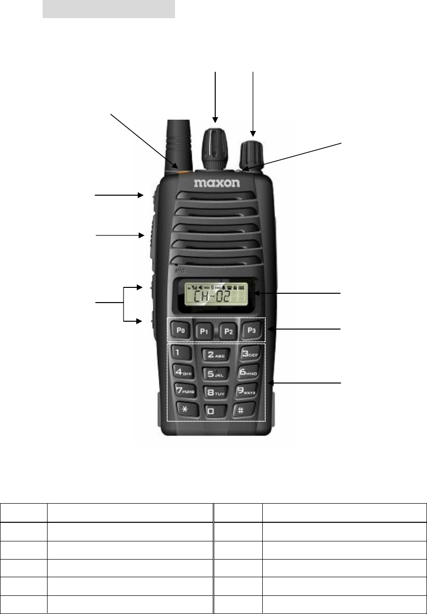
1. Panel Description
(1) Front Panel
No. Description No. Description
1 Power On/Off, Volume Control S/W 6 Up/Down / Select Button
2 Rotary Selector 7 LED Indicator
3 Emergency Button 8 LCD Display
4 Monitor Button 9 Default Programmable Keys
5 PTT Key Optional 10-keypad
12
3
8
4
5
6
7
9
Function Description SL-7402
5/32
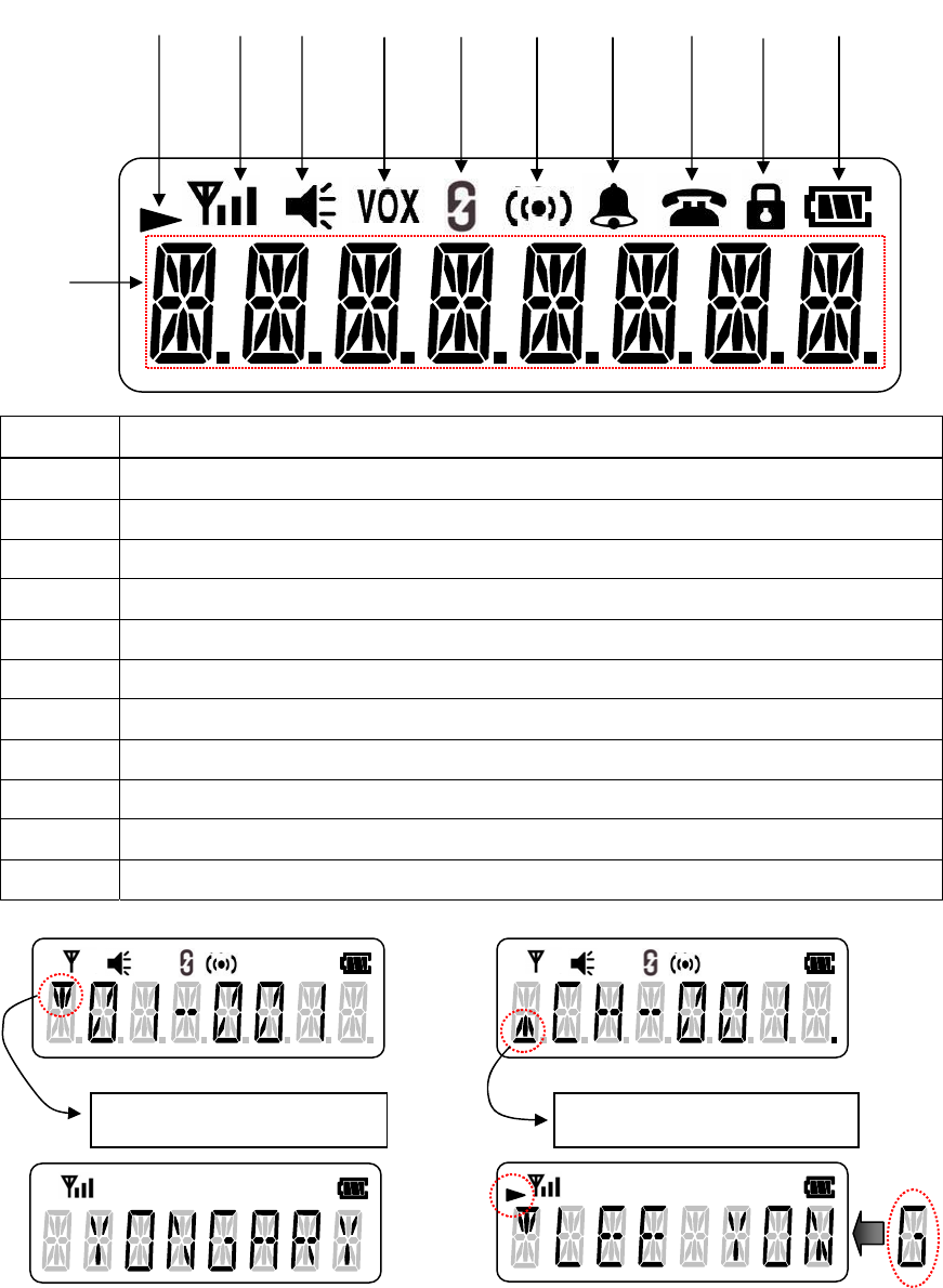
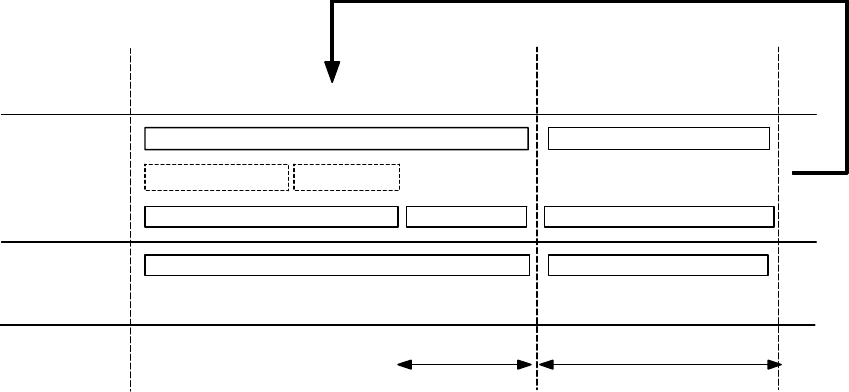
(2) LCD Display
No. Description
CH, Group, Name, Message etc. Display Digit
Scroll Indicator
RSSI Indicator
Monitor Indicator
VOX On/Off Indicator
Scrambler On/Off Indicator
Compander On/Off Indicator
Bell Indicator
Call Indicator
Key Lock On/Off Indicator
Battery Gauge
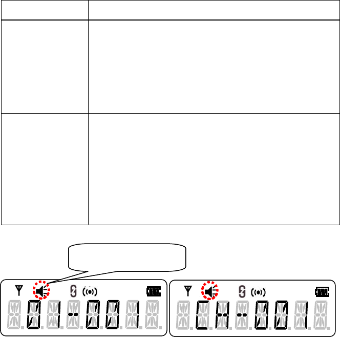
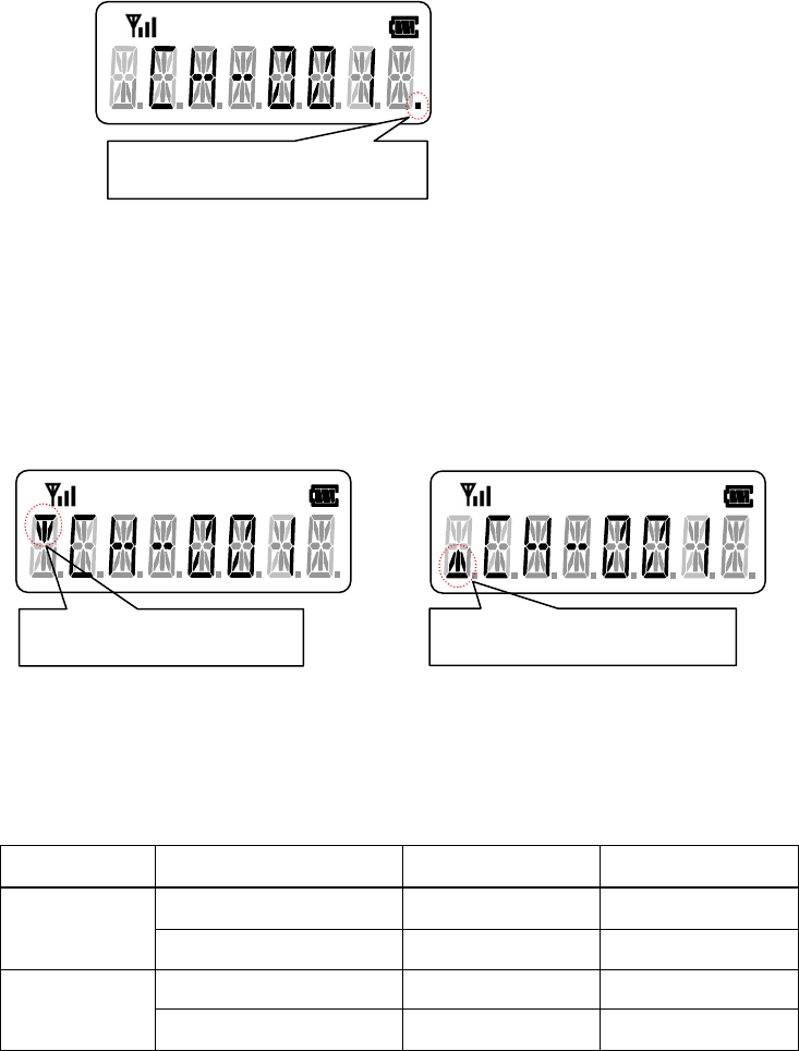
Display Example)
Ex) Group-Channel Display Ex) Channel Display
Ex) Name Text Display Ex) Scroll의 예
Priority Channel Indicator Lookback Channel Indicator
Function Description SL-7402
6/32
(3) Display Option
1) Display Type
- Channel Name Display
z Display only Channel Name when this type is selected.
z Display the Group Number for a second when Group is changed.
z Scrolls when the name is more than 7 characters
- Channel Number Display
z Display only Channel Number when this type is selected.
z Display the Group Number for a sec when Group is changed.
- Group / Channel Number Display
z Display Group & Channel Number when this type is selected.
- Group / Channel Name Display
z Display Group & Channel Name when this type is selected.
z Display ‘/’ between Group and Channel Name as a descriptor.
z Scrolls when the name is more than 7 characters

Function Description SL-7402
7/32
2. Basic Functions
(1) Power On/Off & Volume Control
1) Power On/Off
To turn on the radio, rotate the volume knob clockwise beyond detent.
To turn off the radio, rotate the volume knob the most counter-clockwise
beyond detent.
Ex) Power On
2) Power On Sequence
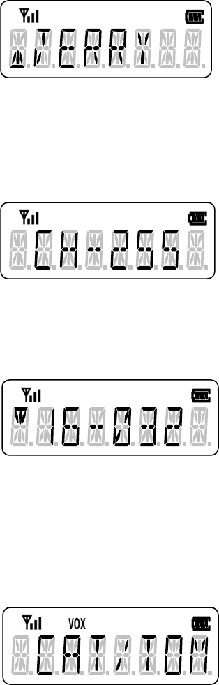
- Initialization & Self Test
Initialization and self test are performed when the radio is turned on.
At this time, if some errors occur, error message shall be displayed.
Ex) EEPROM Error
- Power On Beep Generation (Option)
Beep sounds out after success of Initialization and Self Test.
(Depends on Beep Option)
Function Description SL-7402
8/32
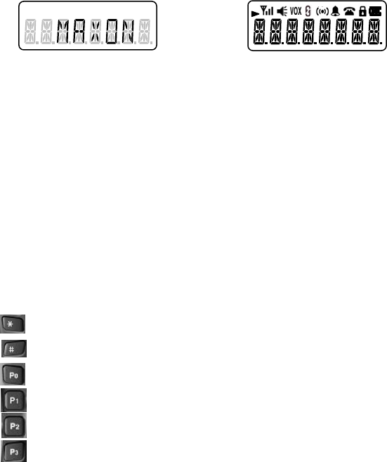
- Display Start Logo (Option)
Display the Start Logo for a second. If there is no predefined start logo, all
digits and icons will be displayed for a second.
Ex1) Start Logo Ex2) Non Start Logo
- Password Check (Option)
Password function is the function that the user who knows the password
can use the radio. (Depends on password option)
Password can be consisted of 1 to 4 numerical digits.
In case of the radio with 10-keypad, 10-keypad can be used to input the
password.
* Usage of keys for inputting password
: Confirm (Enter)
: Delete (Error Beep out if there is no digit to delete.
: Confirm (Enter)
: Digit Value Change
: Next Digit
: Delete
(2) Receiving and Transmitting
1) Receiving
- Channel & Group Selection
z Group Selection
① Rotary Selector
Rotary Selector can be used to select each group up to 16.
If blank group is selected, the radio keeps the last used
channel status.

Function Description SL-7402
9/32
② Programmable Key
To select the group up or down direction, push the
programmed key.
If there are blank groups within the total groups, the blank
group is skipped automatically when group is changing.
z Channel Selection
① Rotary Selector
Rotary Selector can be used to select channel up to 16.
If blank channel is selected, the radio keeps last used
channel status.
② Programmable Key
Push to select the channel up or down direction.
If there are blank channels within the total channels, the
blank channel is skipped automatically when channel is
changing.
- Busy
Busy Status: When receiving a call
Amber color LED turns on in busy status.
Ex) LED Display
Function Description SL-7402
10/32
- Correct Call
Correct Call Status: When proper CTCSS tone or DCS code is decoded.
Green color LED turns on in correct call status
- Monitor Operating
Release squelch and tone option to check whether you can use or not
current channel.
Mode Description
Push Mode Push and hold the key in short time, to enter to
monitor push mode.
Squelch and tone option are released while push
and hold the key.
To return to normal mode, release the monitor key.
Hold Mode Push and hold the key in long time, to enter to
monitor hold mode.
After a confirm beep, monitor operation is held even
if the key is released.
To return to normal mode, push and release the
monitor key once more.
Display Ex.
Group – Channel Display Channel Display
Monitor On Indicator
Function Description SL-7402
11/32
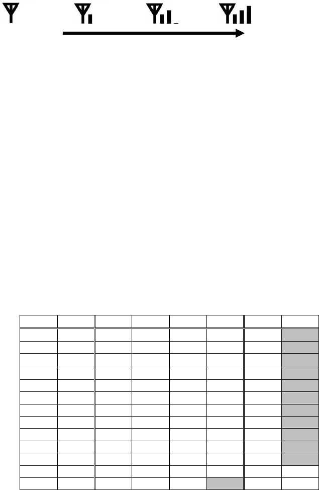
- RSSI (Received Signal Strength Indication)
This function is to indicate the received signal strength.
Display Ex.
Signal Strength
- Receiving Option
z Squelch Level Control
Squelch level is adjustable 1 to 9 step by PC Program or User Set
Mode.
z Sub-Audio Tone
① CTCSS
The radio has a CTCSS tone squelch function which consists of
38 standard tones and 12 non-standard tones.
No. Freq. No. Freq. No. Freq. No. Freq.
1 67.0 14 107.2 27 167.9 40 159.8
2 71.9 15 110.9 28 173.8 41 165.5
3 74.4 16 114.8 29 179.9 42 171.3
4 77.0 17 118.8 30 186.2 43 177.3
5 79.7 18 123.0 31 192.8 44 183.5
6 82.5 19 127.3 32 203.5 45 189.9
7 85.4 20 131.8 33 210.7 46 196.6
8 88.5 21 136.5 34 218.1 47 199.5
9 91.5 22 141.3 35 225.7 48 206.5
10 94.8 23 146.2 36 233.6 49 229.1
11 97.3 24 151.4 37 241.8 50 254.1
12 100.0 25 156.7 38 250.3
13 103.5 26 162.2 39 69.4
Function Description SL-7402
12/32
② DCS (IDCS)
The radio also has a digital coded squelch function which
consists of 104 codes.
No. Code No. Code No. Code No. Code
1 023 27 152 53 311 79 466
2 025 28 155 54 315 80 503
3 026 29 156 55 325 81 506
4 031 30 162 56 331 82 516
5 032 31 165 57 332 83 523
6 036 32 172 58 343 84 526
7 043 33 174 59 346 85 532
8 047 34 205 60 351 86 546
9 051 35 212 61 356 87 565
10 053 36 223 62 364 88 606
11 054 37 225 63 365 89 612
12 065 38 226 64 371 90 624
13 071 39 243 65 411 91 627
14 072 40 244 66 412 92 631
15 073 41 245 67 413 93 632
16 074 42 246 68 423 94 654
17 122 43 251 69 431 95 662
18 114 44 252 70 432 96 664
19 115 45 255 71 445 97 703
20 116 46 261 72 446 98 712
21 125 47 263 73 452 99 723
22 131 48 265 74 454 100 731
23 132 49 266 75 455 101 732
24 134 50 271 76 462 102 734
25 143 51 274 77 464 103 743
26 145 52 306 78 465 104 754
z Signalling (2-Tone, 5-Tone, DTMF)
Î There are three type audio-band tone signaling.
Refer to Signaling section.
z Tone Squelch Option
① Tone Squelch 1 (On/Off)
All Tone Squelch On/Off (Sub-Audio, 2-Tone, 5-Tone, DTMF)
Display Ex.) Display tone squelch status for a second when the
status is changed.

Function Description SL-7402
13/32
② Tone Squelch 2 (On/Off)
Only audio-band tone squelch(2-Tone, 5-Tone, DTMF Squelch)
On/Off
Display Ex.) Display the tone squelch status for a second when
the status is changed.
2) Transmitting
- 송신방법
z PTT Key
Push the PTT (Push To Talk) key to transmit.
z VOX function (Voice Operated Transmit)
This function is to transmit by voice without pressing the PTT key.
The radio can transmit by low and high level voice in accordance with
VOX level 1 to 4.
- Transmit Option
z PTT ID
When transmission is starting, PTT ID which consists of DTMF or 5-
tone depend on system and signaling option can be transmitted.
z TX Power High/Low Control
Each channel can be capable of programmable output power via PC
programmer.
Each channel can be programmed high or low transmit power.
z TOT (Time Out Timer)
This function is to prevent continuous transmitting over than specified
time that is programmed via PC programmer.
z BCLO (Busy Channel Lock-Out)
This function is to prevent transmitting when current channel is in
busy status.
Function Description SL-7402
14/32
z Marked Idle
This option allows transmitting when current channel is in correct call
status even if BCLO option is applied.
z TX Delay
This function is to eliminate the squelch tail on leaving transmission.
The radio transmits the turn off code (or tone) and return to receive
mode after the PTT key is released.
z Roger Beep
When this option is on, beep sound shall be transmitted after the PTT
key is released.
z Clear to Talk
This function is to inform that voice can be transmitted without a loss.
When PTT key is pushed beep sounds out after specified clear time.
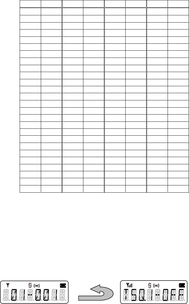
- Talk Around
z This function allows communicating directly with other radios without
the use of a repeater.
z When using this function, the receive frequency is used for both
transmitting and receiving.
z This function shall be off automatically, when the channel is changed.
z Display Ex.
3) Power Save
If this function is activated, the power save function will decrease the amount
of using power when current channel is no busy status and no operations are
being performed.
Function Description SL-7402
15/32
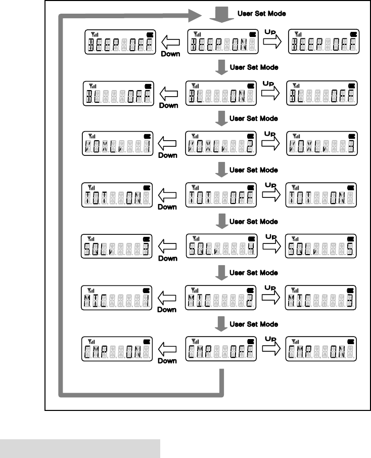
(3) User Set Mode
1) This mode is to set internal settings that are not changed very often.
2) Setting
- Push the User Set Mode key to enter the User Set Mode.
- To select item: User Set Mode Key
- To change value of the item: Up/Down Key
- Exit without Save: Monitor Key (or after 10 seconds without key input)
- Save & Exit: PTT Key
- Items List
z Beep
z LCD Back Light
z VOX
z TOT
z Squelch Level
z MIC Sense
z Compander On/Off
Function Description SL-7402
16/32
3) Setting Ex.
3. Emergency Function
(1) To transmit Emergency Call
Push and hold the emergency key to transmit emergency call. (Push and hold the
emergency key once more to exit this function.)
(2) Effect
1) Alert tone
2) Backlight Blinking (one second interval)
Function Description SL-7402
17/32
(3) Emergency ID
This ID consists of DTMF codes.
(4) Formation of the Emergency Call
EMG Call Start
Sender
Receiver
TX Time
TX
RX
RX
TX / RX
ID(Option)
RX Time
T
X→RX RX →
T
X
Effect(Option)
MIC Mute MIC Unmute MIC Mute
(5) Emergency Call Options
1) Cycle: The number of repetition
2) The number of repetition of Alert Tone
3) RX Time: Time for receiving
4) TX Time: Time for transmitting
5) Channel Type: Fixed Channel / Current Channel

Function Description SL-7402
18/32
4. Scan Function
(1) Description
This function is to monitor a number of channels or channels within a group that
are defined in the scan list.
(Note: Start re-scanning when turning power on if the radio turned off while
scanning)
(2) Scan Type
1) Normal Scan: If there is no predefined priority channel, Normal Scan shall be
running.
2) Priority Scan: If the radio has a predefined priority channel, Priority Scan will
be running. In this case priority channel is checked every three normal
channel scanning.
3) Power On Scan: When turning power on, the radio automatically starts
scanning.
4) Look Back Scan: When using priority scan, the radio will automatically change
to the priority channel when a call is received on the lookback channel. If the
priority channel is not correct call status, return to lookback channel. After
lookback interval time, the radio will repeat the above operation.
- If the priority channel is correct call status, look back scanning will be
stopped and the radio receive a call until the priority channel will be not
correct call status.
(3) Nuisance Delete
This function is to temporarily delete a channel from the scan list.
1) How to use: Push the monitor key while scanning and stopped on the channel
to be deleted.
2) Note: The original scan list is recovered when the radio’s power is reset.
Function Description SL-7402
19/32
(4) Scan List Edit
1) You can use the Scan List Edit Key to add or delete.
2) Display
(5) Priority Channel / Lookback Channel Setting
1) You can set Priority Channel / Lookback Channel using the each setting key.
2) Display
(6) TX Channel on Scan
Transmission channel during scan
Scan Type TX Option Busy No Busy
Priority Scan TX Current Ch. Priority Ch.
Priority Scan Priority Only TX Priority Ch. Priority Ch.
Normal Scan TX Current Ch. TX Inhibition
Normal Scan RX Only TX TX Inhibition TX Inhibition
The Scan List Add Indicator
Priority Channel Indicator Lookback Channel Indicator
Function Description SL-7402
20/32
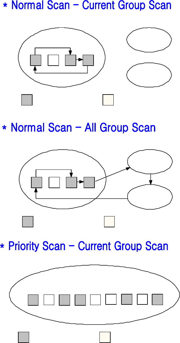
(7) Scan Operation Diagram
Current Group Group x
Group y
Scan Channel Non-scan Channel
Current Group Group x
Group y
Scan Channel Non-scan Channel
Current Group
P
Scan Channel Non-scan Channel
1 2 3 4 5 6 7 8
Scan Order: P →2→3→6→P→8→P→2→P→...

Function Description SL-7402
21/32
5. Signaling Function
You can select signalling type of each channel. Especially 5-tone case, you can
select and set the format of the tone. (for example: ZVEI1, PZVEI, EEA, CCIR1
etc.)
You can select the sending signal code in the TX Code List which depends on the
signaling type of each channel.
In DTMF case, push the PTT key to send the code after inputting or selecting.
In 2-Tone and 5-Tone case, push the Call key to send the code after inputting or
selecting. (Note: The Call Key must be programmed to send 2-tone or 5-tone
code.)
(1) Signaling Type & Transmission
1) DTMF
- Transmission
z Manual Dial: To send the DTMF codes press the numerical key with
programmable key while pressing the PTT key.
① 0 ~ 9, *, #
② P0: ‘A’ tone
③ P1: ‘B’ tone
④ P2: ‘C’ tone
⑤ P3: ‘D’ tone
z Store and Send: Push the PTT key after finishing the DTMF codes
input.
① PTT: Code Save & Send
② Monitor: Cancel (Exit without Save)
③ ‘*’: Special Tone Selection Mode
I. ‘*’: *
II. ‘#’: #
III. P0: ‘A’ tone
IV. P1: ‘B’ tone
V. P2: ‘C’ tone
Function Description SL-7402
22/32
VI. P3: ‘D’ tone
④ ‘#’: Delete
z TX Code Select & Enter
① PTT: Code Save & Send
② Monitor: Cancel (Exit without Save)
③ Up / Down: Code Selection
z Redial
① Redial Key: Display the recent sent DTMF code
② PTT: Send
③ Monitor: Cancel (Exit)
Note: Error beep out if there is no Redial Code.
2) 5-Tone
- Transmission
z TX Code Select Mode
① TX Code Select & Enter Key: Enter to the TX Code Select Mode
② Up / Down Key: Select the code
③ Call Key: Send the code
z TX Code Enter Mode
① TX Code Select & Enter Key (in TX Code Select Mode): Enter to
the TX Code Enter Mode
② Up / Down Key: Edit the code digit
③ TX Code Select & Enter Key (in TX Code Enter Mode): Change
the digit
④ To return to the TX Code Select Mode push the TX Code Select
& Enter Key after the last code editing.
z PTT Key: Save & Exit
z Monitor Key: Cancel (Exit without Save)
z Up / Down
① Code Select Mode: Code Selection
② Code Enter Mode: Digit Code Edit (0 ~ 9, *)
Function Description SL-7402
23/32
3) 2-Tone
- Transmission
z TX Code Select & Enter
① PTT: Code Save & Send
② Monitor: Cancel (Exit without Save)
③ Up / Down: Code Selection
(2) Signaling Functions and Receiving
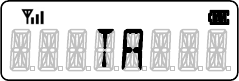
1) ANI (DTMF & 5-Tone)
- Display the received code on the LCD.
- Display the alias text if the received code matches with one of the code in
the RX Code List.
- Display time is 10 seconds.
2) Selcall (DTMF & 5-Tone)
- The radio will do the correspondent action if the received code matches
with current channel ID.
- Action
z LED: LED(Amber Color) Blink Effect
z ICON: Icon Blink Effect
z Alert Tone: Alert Beep Effect
z Squelch: Squelch Effect
3) Code Match Operation
- The radio will do the correspondent action if the received code matches
with one of the code in the RX Code List.
z LED: LED(Amber Color) Blink Effect
z ICON: Icon Blink Effect
z Alert Tone: Alert Beep Effect
z Squelch: Squelch Effect
Function Description SL-7402
24/32
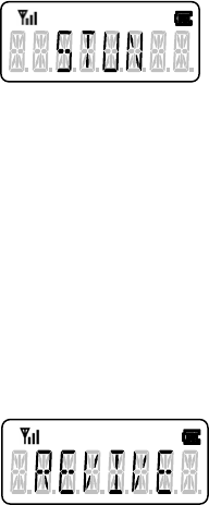
z Stun
① When receiving the Stun Code display the stun message until
the stun mode is released.
② All keys are disabled except the EMG key. (Only Emergency
Call and receiving are possible.)
③ Key pressing except the EMG Key will make Error Beep.
z Revive
① When receiving the Revive code in stun mode the radio return to
normal mode.
② When releasing the Stun Mode Cancel Beep out and the revive
message will be displayed on the LCD for a second.
z Text: The text correspondent with the received code will be displayed,
4) Optional Functions
- Transponder: This function is to send the Alert Tone automatically when
the received code matches with current channel ID.
- Auto Reset Time: After matching status(the received code matches with
current channel ID or one of the codes in the RX Code List) if Auto Reset
Time is elapsed with no busy status return to call standby status.
- Push the monitor key to return to call standby status before Auto Reset
Time is elapsed.
Function Description SL-7402
25/32
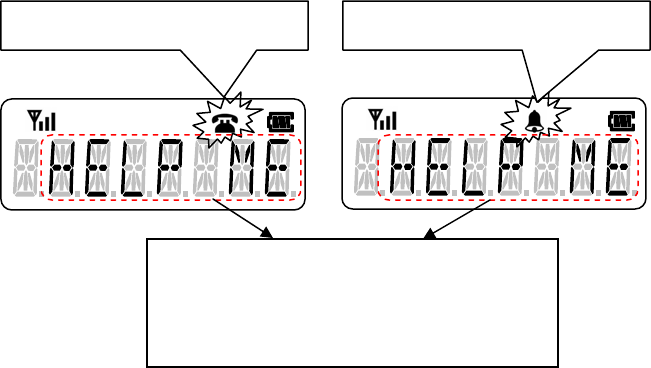
- Remind Time: After matching status if there is no key input correspondent
call icon will be blinked while reminding time.
z Push any key to stop the icon blinking.
z Receiving status will be displayed until any key input.
DTMF Case 5-Tone, 2-Tone Case
Display the correspondent text when the
received code matches with one of the
codes in the RX Code List.
Function Description SL-7402
26/32
(3) Signaling Operation Example
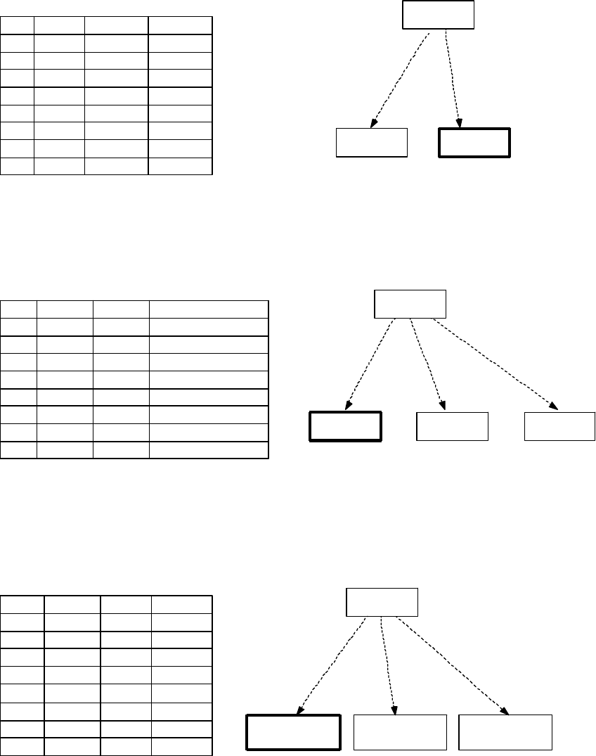
1) DTMF
ANI: Displays the received DTMF code.
Alert: Beeps out if the received DTMF code and Ch. ID are the same.
Code Name Actions
110001 KIMYN X
210002 RYUJG SQL Open
310003 KIMY Alert ON
410004 KIMCG LED ON
500001 NOTHING X
600002 BUSY X
700003 READY X
800004 COMEON X
Receiver2's DTMF RX Code List
CH NO. Signaling CH ID Name
CH 1 DTMF 10001 KIMYN
CH 2 DTMF 10002 RYUJG
CH 3 DTMF 10003 KIMY
CH 4 DTMF 10004 KIMCG
CH 5 DTMF 10005 TWR_SW
CH. 6 DTMF 10006 TWR_HW
CH 7
CH 8
Channel Data
Sender
CH 5
CH ID: 10005
10005
10005
10005
Alert ON
Sender
Receiver 2
10001
Display "KIMYN"
CH 5
CH ID: None
No Response
CH 1
CH ID: 10001
No Response
Receiver 1
10001
Display "10001"
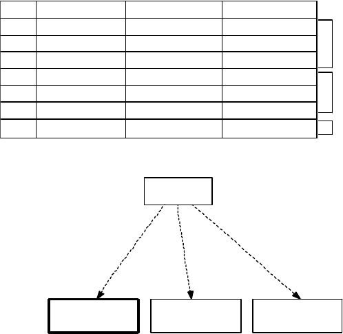
Command: Carries out designed actions if the transceiver receives a valid code.
Code Name Actions
110001 KIMYN X
210002 RYUJG SQL Open
310003 KIMY Alert ON, Icon Blink
410004 KIMCG LED ON
500001 NOTHING X
600002 BUSY X
700003 READY X
800004 COMEON X
Receiver1's DTMF RX Code List
Sender
Receiver 2
10003
Alert ON, Icon Blink
Receiver 3Receiver 1
10003
10003
No Response No Response
Function Description SL-7402
27/32
2) 5-Tone Group Call
No. Signaling Type CH ID CH. Name
15-Tone 10001 KIM
25-Tone 10002 RYU
35-Tone 10003 YONG
45-Tone 20001 KANG
55-Tone 20002 CHUNG
65-Tone 20003 JONG
75-Tone 30001 KWANG
Group A
Group B
Group C
Sender
KIM
100AA
100AA
100AA
Group Call Beep
LCD Blink
(
'Grou
p
'
)
KANG
No Response
KWANG
No Response
Channel Data

Function Description SL-7402
28/32
(4) 5-Tone Table
Tone ZVEI1 PZVEI DZVEI DDZVEI PDZVEI CCIR1 CCIR2 PCCIR EEA Euro
signal NATEL
02400 2400 2200 2400 2200 1981 1981 1981 1981 979.8 1633
11060 1060 970 1060 970 1124 1124 1124 1124 903.1 631
21160 1160 1060 1160 1060 1197 1197 1197 1197 832.5 697
31270 1270 1160 1270 1160 1275 1275 1275 1275 767.4 770
41400 1400 1270 1400 1270 1358 1358 1358 1358 707.4 852
51530 1530 1400 1530 1400 1446 1446 1446 1446 652.0 941
61670 1670 1530 1670 1530 1540 1540 1540 1540 601.0 1040
71830 1830 1670 1830 1670 1640 1640 1640 1640 554.0 1209
82000 2000 1830 2000 1830 1747 1747 1747 1747 510.7 1336
92200 2200 2000 2200 2000 1860 1860 1860 1860 470.8 1477
A2800 970 825 885 825 2400 2400 1050 1055 --- 1995
B810 810 740 810 886 930 930 930 930 571
C970 2800 2600 740 2600 2247 2247 2400 2400 2205
D885 885 885 680 856 991 991 991 991 2437
E2600 2600 2400 970 2400 2110 2110 2110 2110 1062.9 1805
Note
- Group Tone: A (‘*’)
- Repeat Tone: E
z Example: 11111 Î 1E1E1
Function Description SL-7402
29/32
6. Other Functions
(1) Memory Channel
1) Description
- You can memory channels that are frequently used up to 10 memory
channels.
- Programmable key and 10-keypad can be used as a memory channel key.
2) Operation
- In case of no 10-keypad, you can memory channels up to 4 memory
channels.
- If you push the memory channel key, current channel will be changed to
correspondent memory channel like as Direct Channel Function.
- When memory function is activated, the rotary selector position can be
different from current memory channel information.
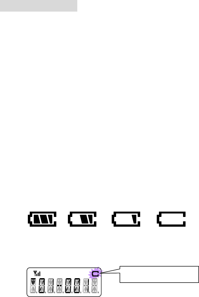
(2) Battery Indication
1) The battery indicator shows approximately how much charge is left.
2) Display (4-Step Display)
3) Low Battery
- Battery Icon will be blinked and warning beep out when the battery is low.
4) Low Battery in Transmitting
- If battery is low when transmitting, next transmission will be inhibited.
Blinking the battery icon
Function Description SL-7402
30/32
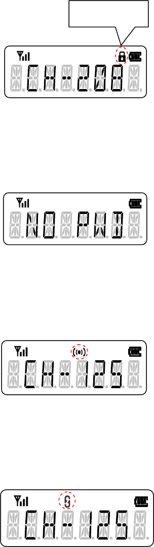
(3) Key Lock
1) All keys are locked except EMG, PTT and Rotary Selector.
- To release the key lock status, push the lock key once more.
2) Display of the Key Lock Status
(4) Transceiver Lock
1) This function is to prevent others from using the radio.
- If you push the transceiver lock key, when the radio has no password
Error Beep out and Error Message will be displayed.
(5) Compander
1) This function is to reduce noise components from the transmitting audio to
provide clear voice quality.
2) Display: The compander icon appears when the function is on.
(6) Scramble
1) This function is to prevent others from easily listening your call.
2) Display: The scrambler icon appears when the scrambler is on.
Key Lock Icon
Function Description SL-7402
31/32
(7) Man Down
Î Optional Function
(8) Lone Worker
If there is no key input within the specified time, warning beep out while warning
duration.
If there is no key input while warning duration, emergency call is transmitted
automatically.

Function Description SL-7402
32/32
7. Function List & User Set Mode Function
Value Function Remark
0None
1Backlight OFF / ON / AUTO
2Beep OFF / ON Controls the whole beep.
3Call
4Channel Down Long Key
5Channel Up Long Key
6Compander OFF / ON
7Group Down Long Key
8Group Up Long Key
9Key Lock
10 Lone Worker`
11 Lookback Channel Setting
12 Man Down OFF / ON
13 Memory Channel 1
14 Memory Channel 2
15 Memory Channel 3
16 Memory Channel 4
17 Priority Channel Setting
18 DTMF Redial
19 Scan List Setting
20 Scan Start / Stop
21 Scrambler OFF / ON
22 Talk Around
23 Tone Squelch1
24 Tone Squelch2
25 Transceiver Lock
26 TX Code Select & Enter
27 TX Power High / Low
28 User Set Mode
29 VOX OFF / ON
30
31
Reserved Compander MIC Sense Squelch Lv. TOT VOX Backlight BEEP
Service Information
Service
Do not tamper with internal adjustments. Damage to the equipment and/or improper operation may result.
There are no user serviceable items inside the radio.
It is recommended that you return your radio to a qualified Maxon Dealer for any service or repairs.
Recycling/Disposal of Batteries
The battery should be recycled at the end of its useful life. Under various state or local laws, such
batteries must be recycled or disposed of properly and cannot be dumped in landfills or incinerators.
For jurther information on how to safely dispose of four used batteries, contact your reseller.
Maintenance
Your SL7402 Radio is designed to be maintenance free. To keep your radio in good working condition:
Clean external surfaces with a clean cloth dampened in a solution of dishwasher detergent diluted in water.
Apply the solution sparingly to avoid any moisture leaking into cracks and crevices. Do not submerge the
radio. Use a non-metallic brush to dislodge stubborn particles, if necessary. Dry the surface thoroughly
with a soft, lint free cloth.
DO NOT use solvents or spirits for cleaning - they may permanently damage the housing.
Clean the battery contacts on the back of the radio with a lint free cloth to remove dirt, grease, or other
foreign material that may impede good electrical contact.
Limited Warranty
Maxon shall have no obligation to make repairs or to cause replacement required which result from
normal wear and tear or necessitated in whole or in part by catastrophe, fault or negligence of the user,
improper or unauthorized alterations, repairs to the Product, use of the Product in a manner for which it
was not designed, or by causes external to the Product. This warranty is void if the serial number is
altered, defaced or removed.
Maxon's sole obligation hereunder shall be to repair or replace the Product covered in the above warranty.