Maxon CIC SP6102 Private Land Mobile Radio for Handheld (VHF) User Manual SL6102manual
Maxon CIC Corp. Private Land Mobile Radio for Handheld (VHF) SL6102manual
Contents
- 1. Users Manual I
- 2. Users Manual
Users Manual
1
SP-6102
About Your SP-6102 Radio
Maxon's SP-6102 radio feature up to 13 groups and up to 16 channel operation per group for a total
channel capacity of 208 channels of superior performance and reliability. Operation and functions for
Maxon's SP-6102 radios are described in this manual.
We urge you to thoroughly read this manual before operating the radio.
Application of some of the functions described in this manual is determined by the system you use. Your
Maxon Dealer will program your radio so that you have the greatest number of functions possible
relative to your needs.
Should you have questions regarding the operation of the radio please consult your Maxon Dealer.
SP-6102 Specification
MODEL: SP- 6102
MODEL CODE: 7858
EQUIPMENT TYPE: Handportable
PERFORMANCE SPECIFICATIONS: TIA/EIA-603/ETSI300.086
BAND: VHF2(148~174Mhz)
CHANNEL SPACINGS: 12.5KHz, 25KHz PROGRAMMBLE
RF OUTPUT POWER: 5 / 1 WATT
MODULATION TYPE: F3E
AUDIO POWER: 500mW ( EXT WITH 16 OHM)
1W ( INT WITH 4 OHM)
INTERMEDIATE FREQUENCY: 45.1MHz
455KHz
CHANNELS: 208 Channel
FREQUENCY SOURCE: SYNTHESIZER
POWER SUPPLY: Li-ION(1750mA)
7.5 VDC NOMINAL EXTREME
+/- 10% VDC EXTREME
Safety Information
WARNING - DO NOT hold the radio in such a manner that the antenna is next to, or touching, exposed
parts of the body, especially the face or eyes, while transmitting.
WARNING -DO NOT allow children to operate transmitter - equipped radio equipment.
CAUTION -DO NOT operate the radio near unshielded electrical blasting caps or in an explosive
atmosphere unless it
is a type especially designed and qualified for such use.
2
CAUTION - DO NOT press and hold the transmit switch (P-T-T) when not actually wishing to transmit.
NEVER use the radio in an aircraft
NEVER use the radio near to sensitive medical equipment or in areas where instructed , e.g. Petrol filling
stations
When used in a vehicle, do not mount the radio unit on or near the Airbag or Airbag activating device.
The use of an accessory not recommended or supplied by Maxon may cause damage to equipment or injury
to personnel , and will invalidate warranty.
When using any of the charging accessories, the mains socket-outlet must be installed near the equipment .
The outlet must not be obstructed and must be easily accessible at all times.
Never attempt to disassemble , modify or repair the unit unless the work is carried out by a Maxon
approved Reseller. Incorrect assembly, modification or repair may cause irreparable damage to your unit
and will invalidate warranty . For service or repair always return your radio to an authorized Maxon
Reseller.
Unpacking Information
Remove and carefully inspect the contents of your package(s) for the following items:
Radio
Battery Pack
Battery Charger
Battery Charger Power Supply
Antenna
Spring Belt Clip
Operating Instructions
If any items are missing, please contact your Dealer or Maxon.
SP-6102 Features
· Wideband frequency separation
· 1 or 5 W programmable output power
· Programmable 12.5/25 kHz channel spacing
· Channel scan
· Priority channel scan
· Look back channel
· CTCSS/DCS/DTMF tone signaling
· Busy channel lockout
· Time-out timer
Scan List Edit
Priority Channel Edit
Description of Radio Components
1) Antenna Receptacle
2) Channel Up/Down Button
3) On/Off - Volume Control
3
4) GWR/PWR Button
5) Lamp / Lock Button
6) Battery Latch
7) Push-To-Talk (PTT)
8) Monitor Button
9) Menu/Scan Button
10) Emergency Button
11) Microphone
12) Accessory Connector
13) Belt Clip
14) Battery
15) Battery Charge Contacts
16) LCD
17) Speaker
Antenna Installation
Fasten the antenna to the radio by turning the antenna clockwise into the receptacle on top of the radio.
Installing and Removing the Battery Pack
To Install:
Position the guides of the battery in line with the radio battery guide rails and slide the battery into position
until a click is heard.
To Remove:
Holding radio in one hand, push and hold battery latch button located in the bottom of the Set , held as if
looking at the back of the unit. Hold radio firmly and slide battery in downward direction while pushing
the battery latch button.
Attaching and Removing the Belt Clip
To Install:
Install belt clip onto the belt clip holder located on the upper left hand corner of the radio, held as if
looking at the back of the unit. Locate slot location in belt clip and push belt clip until a click is heard.
To Remove:
Push and hold release button located at top of belt clip and slide clip off the belt clip holder.
Battery Charging and Care
To ensure peak performance from your radio, the battery pack must
be fully charged. Proper care and charging will allow maximum performance and life of your battery pack.
SPC-3000 Desktop Charger provides 2 hours charging to one radio and one battery.

4
To receive maximum performance from your radio and battery pack, periodically completely discharge and
recharge the battery pack.
Status Indicators and Audible Alert Tones
Your SP-6102 has a sophisticated microprocessor control which provides a series of audible alert tones.
Upon initial power up, a quick melody indicates that the self-test of the microprocessor functions has been
completed satisfactorily. A series of tones may be sounded with any of the following conditions:
· Attempt to transmit on a channel set for receive only
· Attempt to transmit on a channel that is already in use when busy channel lockout has been programmed
into the radio *
· Transmitting time has exceeded time-out timer programmed length *
· Low battery condition
· Selecting a channel with no programmed frequency
* Indicates a function that is initially programmed into the radio by your Maxon Dealer.
NOTE: All audible tones can be programmed off for silent operation.
Status Decription LED color LCD Indication Audible Tone
Normal Power On - Ready N/A Channel number Melody
Call Received Orange Channel number N/A
Correct Call Green Channel number N/A
Busy Channel Orange Channel number N/A
Transmit Red Channel number N/A
Transmit not
allowed Red
Flashing Alternating UL/Channel
number Two beeps
Scanning Normal Scan mode Green
Flashing Group number or channel
number (remove) N/A
Priority Scan Mode Green
Flashing Group number or channel
number (remove)
Priority Look
BackScan Mode Green
Flashing PS/Channel number N/A
Scan
Edit Edit scan list N/A Scan N/A
Priority
Edit Edit Priority
channel N/A Pscn N/A
Warning Low Battery Red
Flashing Low_-BATT 3 beeps
Busy Channel
lockout orange Busy-Lock Single beep
TX Inhibit N/A PENALTY
Two beeps
Time-out-timer N/A TIME-OUT
Single beep/3
beeps repeated
Error Unlock N/A UNLOCK Two beeps
Operation Mode
This section provides general descriptions of the operating modes of the SP-6102 Radio.
Power Off Mode
The SP-6102 shall enter Off mode when the On/Off Volume knob is rotated to the most counter-clockwise
position, beyond the detent. Upon entering Off mode, the radio shall store its current channel(if Power On
Channel function is disabled via PC programmer).
Power On Mode
The SP-6102 shall enter Power-On mode when the On/Off Volume knob is rotated clockwise beyond the
detent. Upon entry of the Power-On mode, the radio shall perform the 5 times power-on alert to indicate
that it has been turned on.
5
Menu Button
you can enter the menu mode by pressing 2seconds more menu/scan button.
It is possible to enable/disable or change options like below in menu mode.
beep(on/off), dtmf(on/off), password(on/off), vox(on/off), squelch level(1~10),
vox level(1~9), vox delay time(1~6).
VOX (Voice operated transmit)
This is the function that the radio can transmit by voice without pressing the PTT key.
The radio can transmit with low and high voice in accordance with Vox level 1~9.
Vox delay level 1~6 decide continue or stop how many tiransmit time when the Tx is finished.
This function set as pc program or menu mode.
High / Low Power
The radio shall be capable of programmable output power.
Each channel can be programmed via pc programmer to have either high or low power.
Or it is set by pressing G/H/L button, then display H or L icon.
Cloning
Frequencies and functions can be programmed from radio to radio by using a cloning cable.
Lamp
This function can be operate whenever press the lamp/Lock button.
LCD and Keypad Back Lighting on/off is toggled whenever press the lamp/lock button.
After backlight is ON, it will be Off automatically in 10 seconds.
Key Lock
This function can disable all keys execpt PTT, Monitor, Lamp, Emergency Key.
6
This function is set when holding the Lamp.Lock button 2 seconds or more and padlock icon is
displayed.
Lock function is not disabled although power off and then power on again.
To disable Lock function, press the Lamp/Lock button again 2secs or more.
Battery Indicator
It displays charging level of battery.(1~7)
Upon detection of low battery condition, the radio shall emit three beeps repeatedly
with display message "LOW-BATT". Radio continuously flashes the red led for the duration of 500ms
to indicate a low battery condition, the radio shall transmit the audio.
If low battery, the radio can transmit continuously but out power is only low power and then low battery
alert shall be given and displayed
SquelchLevel
This function enables speaker when the receving signal level is more than selected level and disable
speaker
when it is less than seleted level. You can set this option at PC Program or SQ level item in menu mode.
In menu mode case, display "SQLv + number" and you can select 1~10 as up/dn button.
Group Button
SP-6102 radio can use maximum 13 groups.
Each group has maximum 16 channels and one priority channel.
The group that you want can be set by PC program.
if a group set, display current group number at left side below on LCD.
In group mode you can edit scan list channel and priority channel with your own hands with the radio.
Press the TX power/group button 2 secs or more, then display "GRP" on left side LCD bottom.
At this time you can move to the group you want by using up/dn button.
When display the group button, you can exit this function with pressing PTT.
7
password
Password function is the function that the user knows the password can use the radio.
You can set password enable and the password code at pc program. And you can set password
enable/disable by programmable key (password and menu option). Display “0000” on LCD and “↓” at
currently place that you can enter the password code. At this time you can enter the password code by
using Up/Dn button.
To move next place, press PTT key. When you press the PTT key at the last 4th place after enter the all
code,
If the code is not correct, and then display “0000” again.
To disable password function, you can select On/Off by using Menu or programmable key(password
option).
If you enable password at the Menu Mode of the radio programmed without password, then default
password code set “1234”
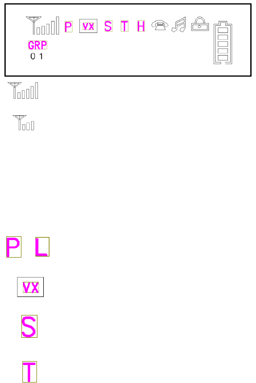
6) Icon
<Transmitting Icon >
* Hi power: Antenna bar is full.
* Low power :Antenna bar is 3.
<Receiving Icon>
Change antenna bar 0~5 by receving signal sense.
vox
Current channel is scan
channel
Current channel has a sub
tone.
1 2 3 4 5 6 7
/P : current channel is priority channel.
L : current channel is lookback
channel.

8
Menu / Scan Button
①Pressing the Menu/Scan Key : scan operating
② Pressing the menu/Scan Key 2 seconds or more : enter the menu mode
Channel UP / DOWN
①Normal : Select a channel.
Menu ②Mode : On/Off or change Option in the Menu mode.
Password ③: Channel UP/DOWN.
GRP / PWR Button
①Short Pressing : Select POWER LOW / HIGH.
②Long Pressing : GROUP MODE .
(GROUP selecting use CH UP / DOWN KEY)
PASS WORD :③ Move the cursor to prev/next digit..
LAMP / LOCK Button
①Short pressing : LAMP and Back Light ON / OFF
②Long pressing : KEY LOCK
* You can use PTT, Monitor, EMG, Lamp.Lock Key only
PTT Button
①Press and Hold to transmit. Release to receive mode.
②Power on with press and holding PTT Key to see software version.
MONITOR Button
H : Tx power is high
L : Tx power is Low.
This icon is displayed if there is a group.
Display when Key_Lock option is On.
Display when Beep is On.
Display when DTMF is set.
Display charging level of battery.
/
9
Release squelch and tone circuit to check whether you can use or not current channel.
EMG Button
①transmit DTMF ID 3 times and generate warning audio alert during 5secs.
Scan Modes
Scanning is a Dealer programmable feature that allows you to monitor a number of channels or channels
within a Group. Your Dealer will help you define a scanning mode and your channel "scan list" .
Normal Channel Scan
During programming of the radio, any channel can be selected as a scanned channel. The scan list will be
activated by switching to the channel that was selected as the scan list channel during programming of the
system parameters. The user shall active scanning by selecting the scanned channel for current channel.
While the radio is scanning, the LED shall flash green as the radio scans. Once the radio has enabled scan,
the radio shall traverse through the pre-programmed scan list. The time spent on receiving a channel in the
scan list is referred to as the scan speed time. When an incoming call is detected and decoded, scanning
shall stop and the radio shall enter Un-muted Busy Mode or Correct Call Mode. After the call has ended,
the radio shall enter Un-muted Busy Mode or Correct Call Mode for a pre-programmed period of scan wait
time. If the radio receives a call from the same caller before the scan wait time expires, the radio shall re-
enter Un-muted Busy Mode or Correct Call Mode and the scan wait time shall be reset. If the user is
permitted to respond to the caller, the scan wait time shall be reset. When the scan wait time expires, the
radio shall resume scanning.
Priority Channel Scan
This scan function can be set by PC program option. This function operates only when priority channel is
set. if radio has not a priority channel, this function not work although radio has scan channels. SP-6102
Radio scan which receiving signal or not at priority channel between scan channel and scan channel during
scanning each scan channel. If you try to TX on priority scanning, SP-3200 radio transmits according to
TX option by PC Program. Green led blinks also. Press the scan button or up/dn button to exit this function.
Other Scanning Features
This function makes the radio scanning between priority channel and lookback channel.
When the current channel is the lookback channel, The Priority Lookback Scan will auto_start.
Scan channel is only 2 channel (current lookback channel and priority channel). Lookback channel is
displayed “L” on Lcd. The lookback channel can be set by Pc Program. Other fuction is the same normal
scan function.
·Scan Channel Delete: To temporarily delete a channel from the scan list, simply press the G/H/L button
while scanning and stopped on the channel to be deleted. This will remove that channel from the scan list
until the channel is changed or the radio's power is reset. When power is restored or the scan list channel
position is again selected, the original Dealer programmed scan list will be activated.
· CTCSS/DCS/DTMF Scanning: The SP-6102 can be programmed by your Dealer to scan for tone. This
will help block out unwanted calls.
· Normal Scan TX: Allows a transmission only after a call is received, depending on the programmed
scan delay time. After the scan resumes, and a transmission is made, the radio will sound an alarm (two
beeps) , display_TX Inhibit and will not allow a transmission.
· Priority Scan TX: Allows a transmission after a call is received depending on programmed scan delay
time. The transmission will
be made on the channel that the call was received. After the scan resumes, if a transmission is made, the
radio will transmit on the programmed priority channel.
10
· Priority Only TX: Allows a transmission on the priority channel when scanning and not stopped on an
active channel. It can also be programmed to ( Remove) will always transmit on the priority channel if
scanning
or stopped on an active channel.
· Receive Only Scan: This allows only reception. If a transmission is made at any time, the radio will
sound an alarm (two beeps) ,, display TX inhibit and will not allow the transmission.
Scan List Edit
This function is editable and displayed when the radio sets up the group scan . You can edit your pre-
programmed Group Scan List by adding or deleting scan list from the Group Scan List.
To activate scan list editing, press the Menu button until the radio enters ‘Scan List Edit Mode’. Upon
entering ‘the Scan List Edit Mode’, the LCD will indicate the “ScnL ” message. To exit the scan list edit
function, Press the PTT.
The radio will display the scan channel number by ‘S’ Icon On or Off. You can change the scan channel by
up or down button. To add or delete this channel from the scan list, press the monitor button. When added,
the ‘S’ Icon will display on the LCD display window. When deleted, the ‘S’ Icon will disappear on the
LCD display window.
Priority Channel Edit
This function is editable and displayed when the radio sets up the group scan . To activate Priority channel
editing, press the Menu/scan button until the radio enters ‘Priority channel Edit Mode’. Upon entering ‘the
Priority channel Edit Mode’, the LCD will indicate the “Pscn ” message. To exit the Priority channel edit
function, Press the PTT.
The radio will display the Priority channel number by ‘P’ Icon On or Off. You can change the Priority
channel by up or down button. To change the priority channel, press the monitor button. If selected the
priority channel, the ‘P’ Icon will display on the LCD display window. When deleted, the ‘P’ Icon will
disappear on the LCD display window.
The Priority channel is only one setting up the each Group. If pressed the monitor button, Current Channel
is changed the Priority channel and then previous priority channel is deleted.
if the look back channel is setting up in the current Group, it can not deleted the Priority channel and the
Look back channel is not changed the Priority channel
Squelch Options
The radio shall support three different squelch options: CTCSS, DCS, Squelch defeat(Monitor). Each
channel shall have its squelch option set during dealer programming. For each transmit operation, the
squelch option shall be implemented if the channel is deemed not busy.
CTCSS
The radio shall support the 47 CTCSS tones and non-standard CTCSS tones ranging from 50Hz to 300Hz
in 0.1Hz increments. All the tones shall be set up during dealer programming.
• TX operation : Upon pressing PTT, the radio shall encode the channel’s programmed CTCSS tone and
enter TX mode. The tone shall last for the duration of the transmission.
• End of TX operation : Upon leaving TX mode, the radio may employ dealer programmable squelch tail
elimination functions.
• RX operation : When the proper CTCSS tone is decoded, the radio shall enter correct call state from busy
state. When the proper CTCSS tone is no longer being decoded, the radio shall enter busy state from
correct call state.
DCS
11
The Radio shall support the encoding and decoding of 83 normal and inverted DCS data.
• TX operation : Upon the pressing of PTT, the radio shall encode the programmed DCS bit pattern for the
selected channel and enter TX mode. The data shall last for the duration of the transmission.
• End of TX operation : Upon leaving TX mode, the radio may employ squelch tail elimination. This shall
be done by sending a turn off code.
• RX operation : The radio shall decode the incoming data stream to determine if there is a match with the
pre-programmed DCS data. If the DCS data is properly decoded, the radio shall enter correct call state
from busy state. When the proper DCS data is longer being decoded, the radio shall enter busy state from
correct call state.
Programming & Cloning
The SP-6102 radios require the programming cable. With the 9 pin connector installed on the computer,
take the other end of the programming cable and insert it in the receptacle located on the Mic Jack of upper
position on the radio.
Reading
(1) Ensure that radio’s power switch is in the “OFF” position.
(2) Connect the programming cable through mic jack.
(3) Place the radio in the pc program mode by holding the radio’s monitor switch and then turning radio
power switch to the “ON” position. Release the monitor switch on the first led flash(In this time, the
radio display “PC PROGRAM” message on LCD).
(4) Press the Read button on PC Program. The LED shall glow red and programming will be start.
Then display “READING” on LCD.
(5) After programming, the radio display "COMPLETED" message on LCD.
Writing
(1) Ensure that radio’s power switch is in the “OFF” position.
(2) Connect the programming cable through mic jack.
(3) Place the radio in the pc program mode by holding the radio’s monitor switch and then turning radio
power switch to the “ON” position. Release the monitor switch on the first led flash(In this time, the
radio display “PC PROGRAM” message on LCD).
(4) Press the Write button on PC Program. The LED shall glow red and programming will be start.
Then display “WRITING” on LCD.
(4) After programming, the radio display "COMPLETED" message on LCD.
Cloning
The SP-6102 radios require the cloning cable. The frequencies and functions can be programmed from
radio to radio by using a cloning cable.
(1) Ensure that both radio’s power switches are in the “OFF” position.
(2) Place the master radio(the radio which already has desired program information in the EEPROM) in
the data master mode by holding the radio’s monitor switch and then turning radio power switch to the
“ON” position(the yellow LED on the radio flashes). Release the monitor switch on the thirth led
flash(In this time, the radio display “MASTER” message on LCD).
(3) Place the slave radio(the radio which is not programmed, or has program information that will be
revised) into data slave mode by holding the radio’s monitor switch and then turning the radio power
12
switch to the “ON” position(the yellow LED on the radio flashes). Release the monitor switch on the
second led flash(In this time, the radio display “SLAVE” message on LCD).
(4) Connect the cloning cable through mic jack.
(5) Press the slave radio’s monitor switch. The LED shall glow green.
(6) Press the master radio’s monitor switch. The LED shall glow red. And Cloning will start.
(7) After cloning, the slave radio display "COMPLETED" message, and the master radio display
“MASTER” message on LCD. Press monitor switch, and then the radio will repeat step 6).
(8) For cloning other radios, repeat step 3) through 7).
Service Information
Service
Do not tamper with internal adjustments. Damage to the equipment and/or improper operation may result.
There are no user serviceable items inside the radio.
It is recommended that you return your radio to a qualified Maxon Dealer for any service or repairs.
Recycling/Disposal of Batteries
The battery should be recycled at the end of its useful life. Under various state or local laws, such batteries
must be recycled or disposed of properly and cannot be dumped in landfills or incinerators.
For jurther information on how to safely dispose of four used batteries ,contact your reseller.
Maintenance
Your SP-6102 Radio is designed to be maintenance free. To keep your radio in good working condition:
Clean external surfaces with a clean cloth dampened in a solution of dishwasher detergent diluted in water.
Apply the solution sparingly to avoid any moisture leaking into cracks and crevices. Do not submerge the
radio. Use a non-metallic brush to dislodge stubborn particles, if necessary. Dry the surface thoroughly
with a soft, lint free cloth.
DO NOT use solvents or spirits for cleaning - they may permanently damage the housing.
Clean the battery contacts on the back of the radio with a lint free cloth to remove dirt, grease, or other
foreign material that may impede good electrical contact.
Limited Warranty
Maxon shall have no obligation to make repairs or to cause replacement required which result from normal
wear and tear or necessitated in whole or in part by catastrophe, fault or negligence of the user, improper or
unauthorized alterations, repairs to the Product, use of the Product in a manner for which it was not
designed, or by causes external to the Product. This warranty is void if the serial number is altered, defaced
or removed.
Maxon's sole obligation hereunder shall be to repair or replace the Product covered in the above warranty.
FCC Warning Statement
Any changes or modifications to the equipment not expressly approved by
the party responsible for compliance could void user’s authority to operate
the equipment.