Maxon CIC SP7402 UHF LMR User Manual
Maxon CIC Corp. UHF LMR Users Manual
UserManual.wiki
>
Maxon CIC
>
SP7402 User Manual
Users Manual
Navigation menu
Upload a User Manual
Namespaces
Wiki Guide
HTML
PDF
Info
Views
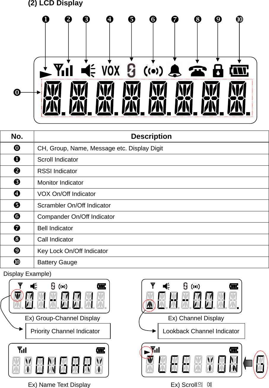
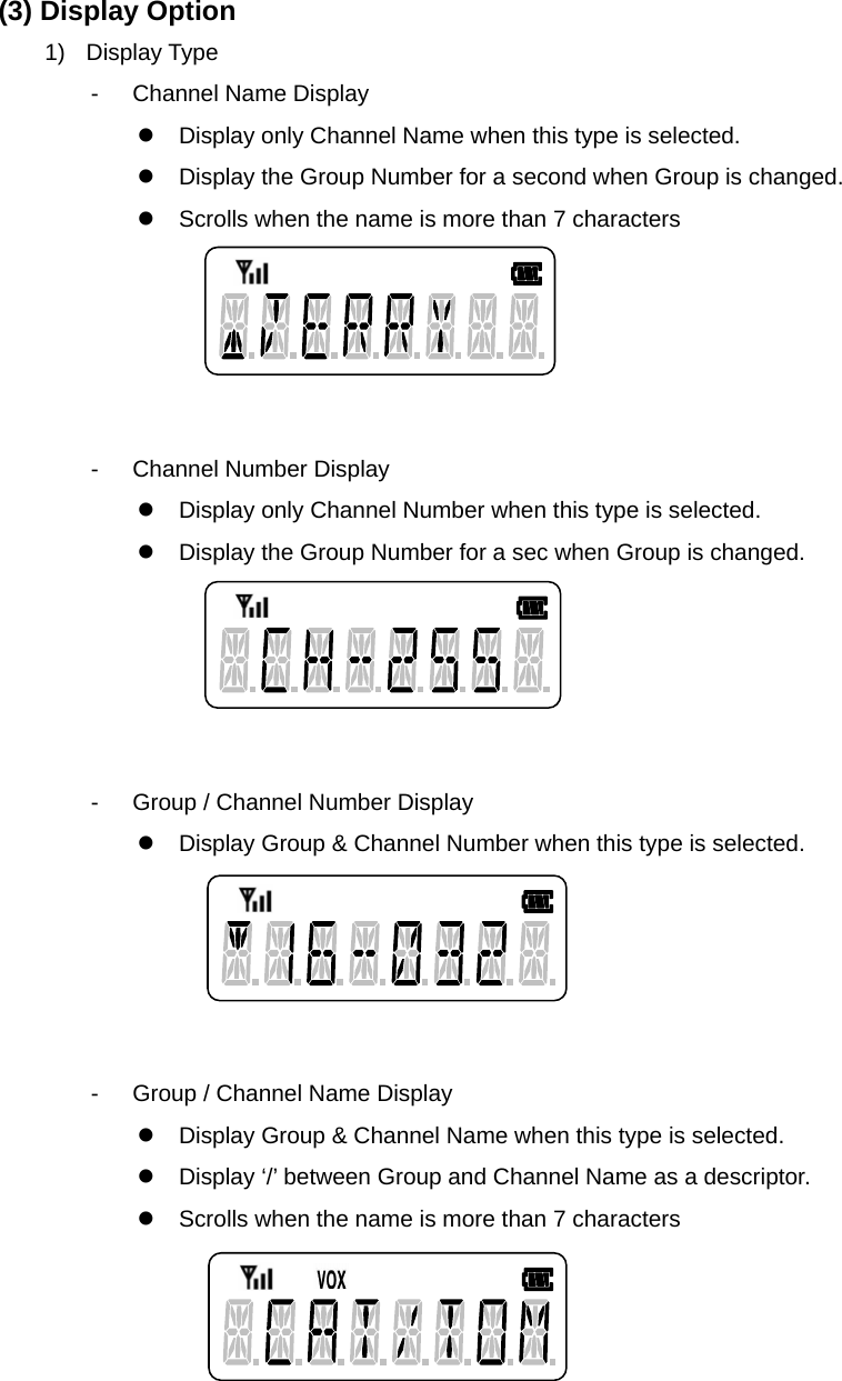
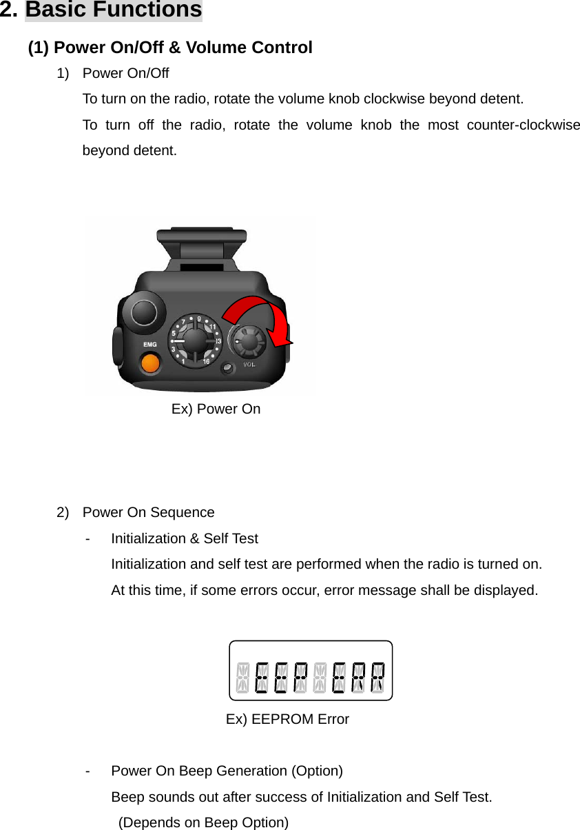
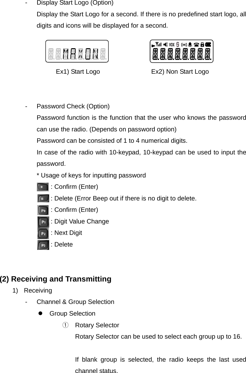
User Manual
Discussion / Help
Navigation