Maxon Electronics Australia MM-5100 Maxon Australia 1X CDMA Voice/Data Modem User Manual Hardware Manual
Maxon Electronics Australia Pty. Ltd. Maxon Australia 1X CDMA Voice/Data Modem Hardware Manual
UserManual.wiki
>
Maxon Electronics Australia
>
MM 5100 User Manual
Users Manual
Navigation menu
Upload a User Manual
Namespaces
Wiki Guide
HTML
PDF
Info
Views
User Manual
Discussion / Help
Navigation
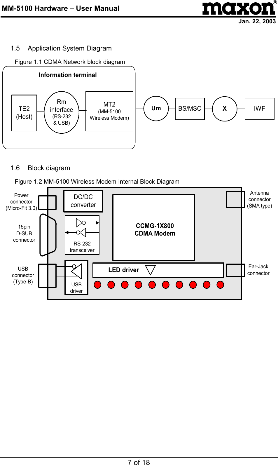
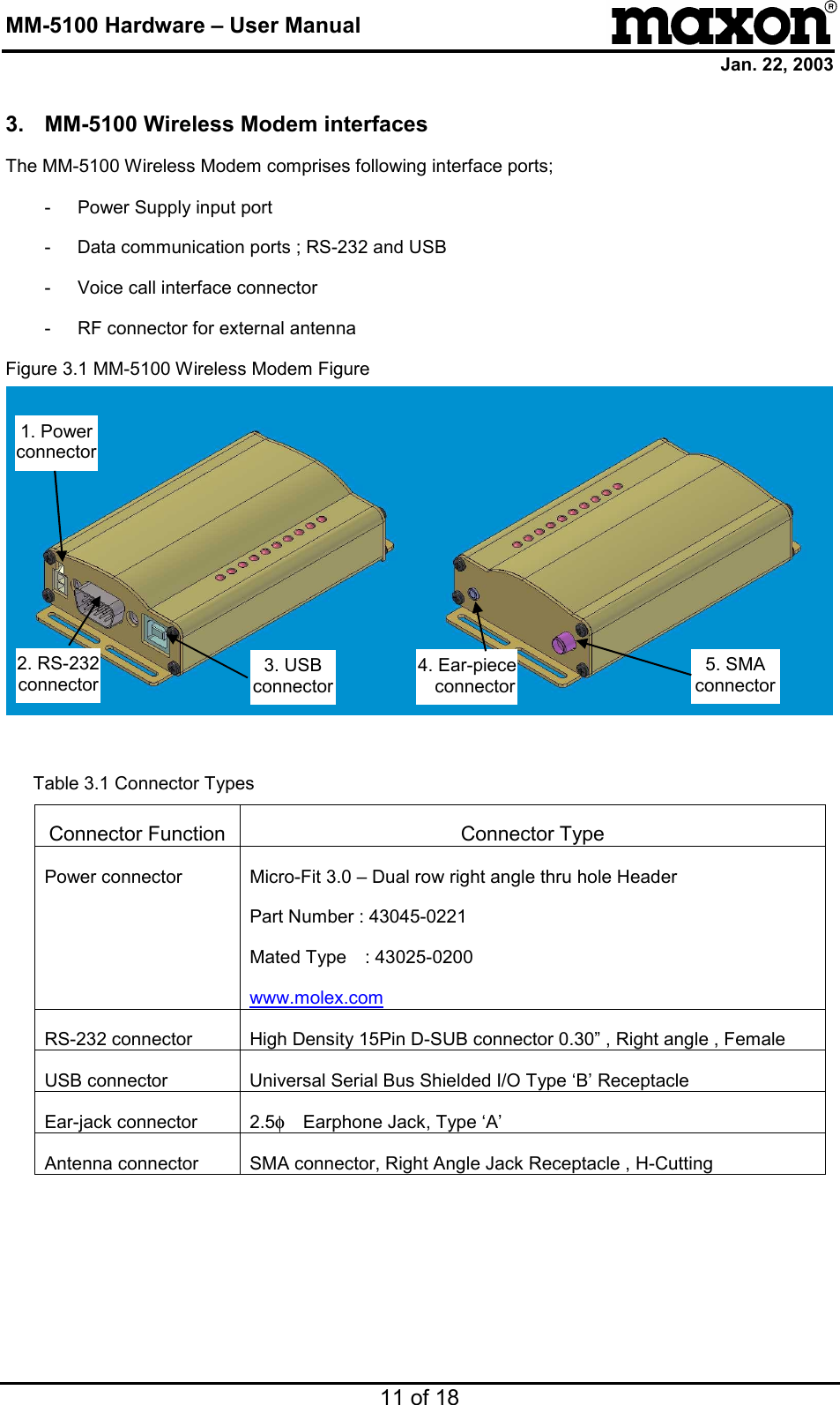
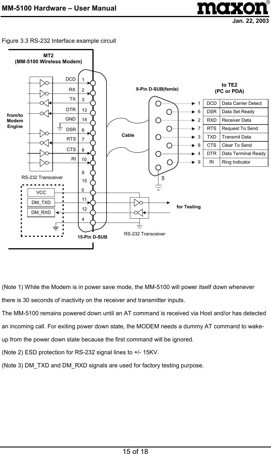
![MM-5100 Hardware – User Manual Jan. 22, 2003 6 of 18 1.3 MM-5100 Wireless Modem overview The MM-5100 Wireless Modem performs data communication functions between Host and IS-95 CDMA Cellular station. The MM-5100 Wireless Modem incorporates the wireless-modem functionality together with the RS-232 and USB driver and DC/DC down converter, Voice interface. The MM-5100 Wireless Modem connects directly to HOST computer utilizing a RS-232C or USB V1.1 interface. The Host signals are converted to the RS-232C or USB 1.1 signal levels. The MM-5100 Wireless Modem functionality is specifically controlled from the Host via AT command sets. Designed to meet the requirements for Telstra’s CDMA markets, the MM-5100 will operate over the following TX /RX frequency ranges: TX frequency 824.73MHz ~ 848.19MHz RX frequency 869MHz – 894MHz Wide range of supply voltage is from 6V to 36V which provides compatibility for platforms utilizing a vehicle and battery design. The MM-5100 Wireless Modem power saving mode is controlled from the Host via AT command. 1.4 Features - IS-95A, B, and cdma 2000-1X CDMA Protocol Support - Standard RS-232 and USB Rev. 1.1 Interface - Remote controlled by AT command set - DATA Transmission up to 153Kbps [network limited] - LED indicating of the modem status - Small size and lightweight](https://usermanual.wiki/Maxon-Electronics-Australia/MM-5100/User-Guide-319091-Page-6.png)