Maxon Electronics Australia MM-5100U CDMA 1xRTT USB Boice/Data Modem User Manual FCC ation
Maxon Electronics Australia Pty. Ltd. CDMA 1xRTT USB Boice/Data Modem FCC ation
UserManual.wiki
>
Maxon Electronics Australia
>
MM 5100U User Manual
Users manual
Navigation menu
Upload a User Manual
Namespaces
Wiki Guide
HTML
PDF
Info
Views
User Manual
Discussion / Help
Navigation
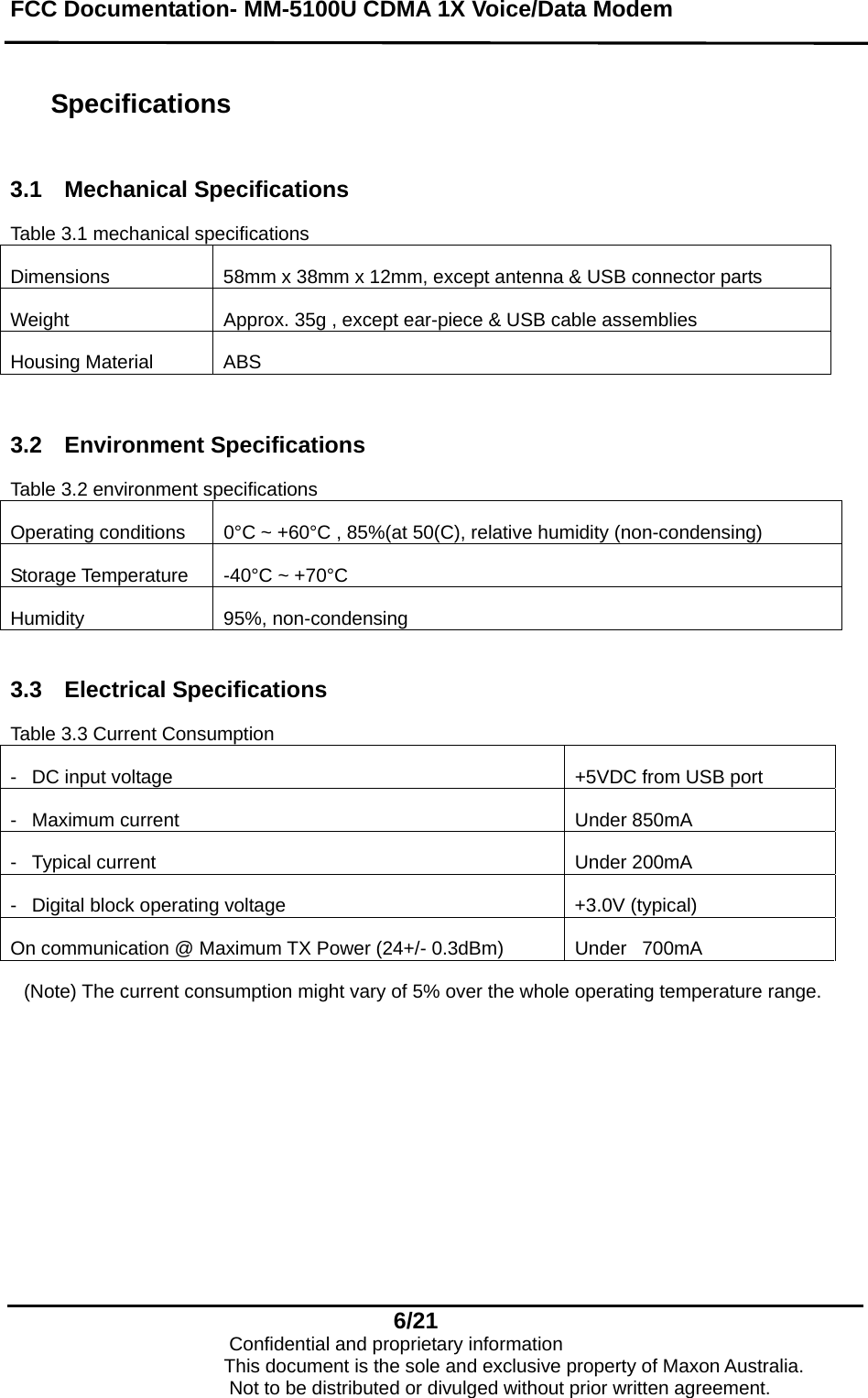
![FCC Documentation- MM-5100U CDMA 1X Voice/Data Modem 2. Product Overview 2.1 Overview The MM-5100U CDMA 1X Voice/Data Modem provides the most convenient environment for wireless voice communication, wireless internet and wireless e-mail at up to 153kbps of data rate anywhere. This modem functions as a wireless Voice/Data Modem, a modem, a mobile phone and allows you to connect to the Internet, send and receive e-mail, connect to a corporate network, and make phone calls, without the need of a network cable or phone line. The MM-5100U card performs data communication functions between Host and IS-95 CDMA Cellular station. 2.2 What is the MM-5100U CDMA 1X Voice/Data Modem - IS-95A, B, and cdma2000-1X CDMA Protocol Support - Remote controlled by AT commands - DATA transmission up to 153Kbps [network limited] - LED indicating of the modem status 2.3 Supplied accessories - MM-5100U CDMA 1X Voice/Data Modem (1) - Ear-piece assembly (1) - USB interface cable assembly (1) - Driver CD (1) 3. 5/21 Confidential and proprietary information This document is the sole and exclusive property of Maxon Australia. Not to be distributed or divulged without prior written agreement.](https://usermanual.wiki/Maxon-Electronics-Australia/MM-5100U/User-Guide-402021-Page-5.png)