Maxtronic Co FIDY Disk Array User Manual Fidy4400 Ch5
Maxtronic International Co Ltd Disk Array Fidy4400 Ch5
Contents
users manual 6

Chapter 5 : " Hot Swap "
This chapter explains how to remove and install the "Hot-Swap" parts
without interrupting the data access while the disk array is on.
The "Hot-Swap" parts include :
Hard Disk Drives
Cooling Fans
Follow the steps below and refer to the diagrams to remove and
install the "Hot-Swap" parts.
5-1
Hot Swap
5-2
Removing / Installing Hard Disk drives
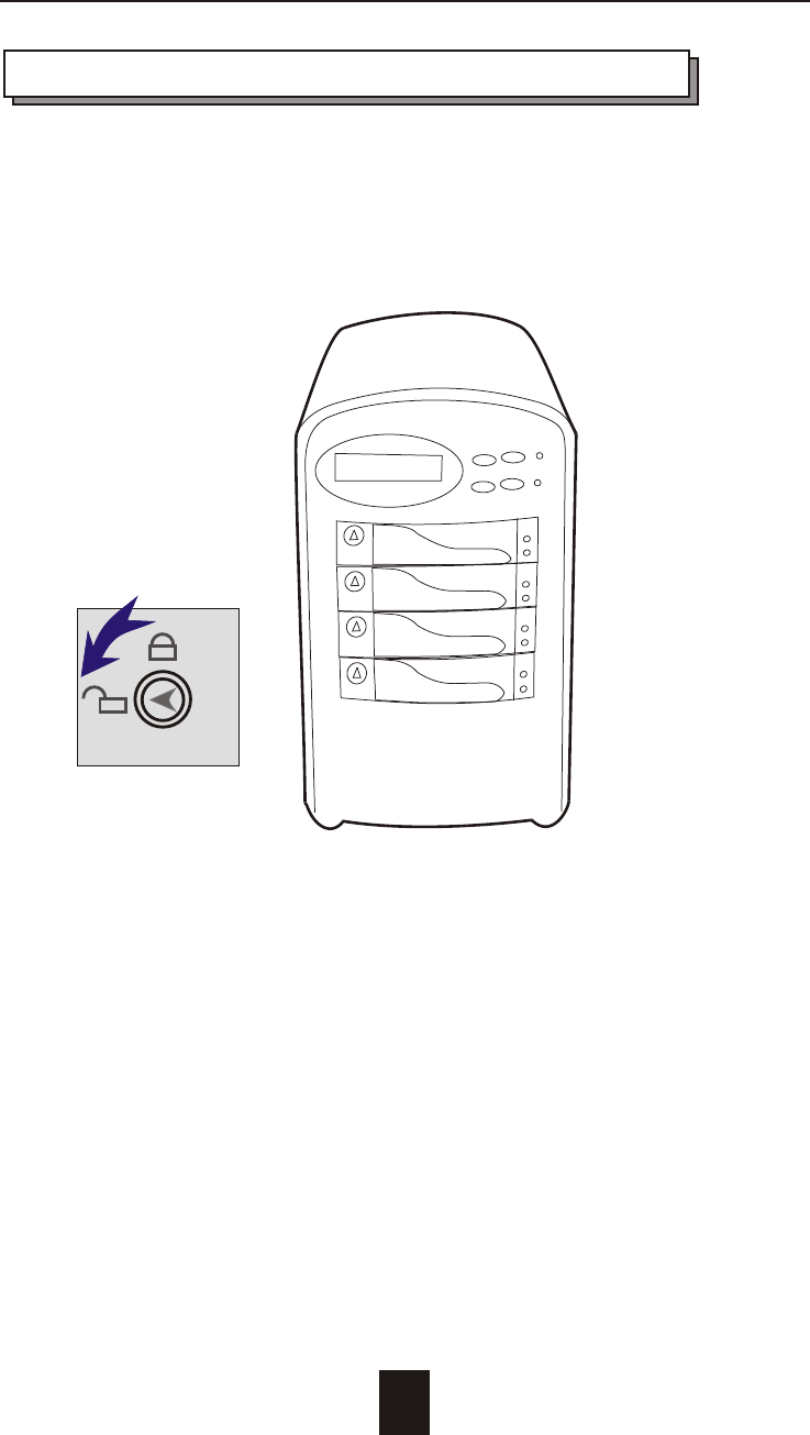
a. Unlock the HDD tray
(When a HDD error occurs, the HDD LED indicator lights up "RED")
Figure : Swap HDD ( Unlock )
5-3
Hot Swap
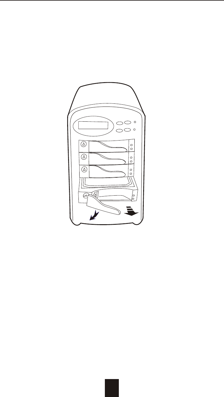
b. Gently pull-out the HDD tray
Figure : Swap HDD ( Pull-out )
Hot Swap
5-4
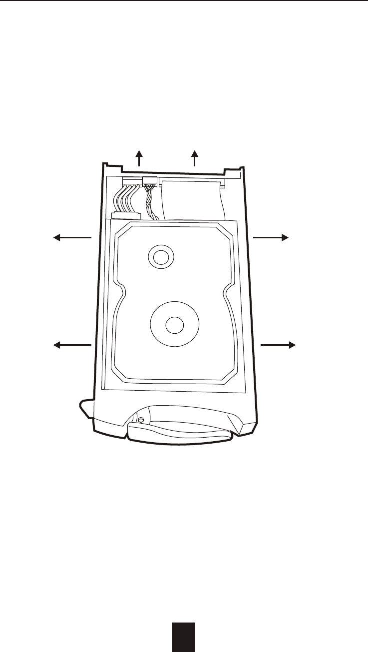
c. Unscrew and unplug the cables
Figure : Swap HDD ( Unplug cables )
Unscrew
Unplug Cables
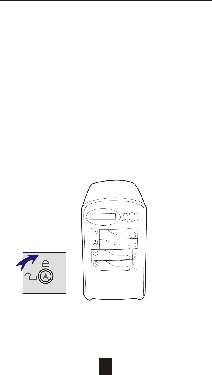
Figure : Swap HDD ( Lock Up )
Hot Swap
5-5
d. Replace with a new Hard Disk Drive
It must be same capacity or greater than the faulty drive, if you
replace with a Hard disk Drive of insufficient capacity, the Disk
Array's built-in buzzer will sound and the intelligent Auto-Rebuild
function will not be started.
* For best performance, we recommend you swap with an
identical Hard Disk Drive.
e. Gently Slide-in the HDD tray and lock up to start
the Auto-Rebuild
When you have installed the replacement disk drive, screw in all
the screws and plug in the cables, you may now gently slide in
the HDD tray into the chassis and lock up it.
* Data Auto-Rebuild will be started automatically when you lock
up the HDD tray.
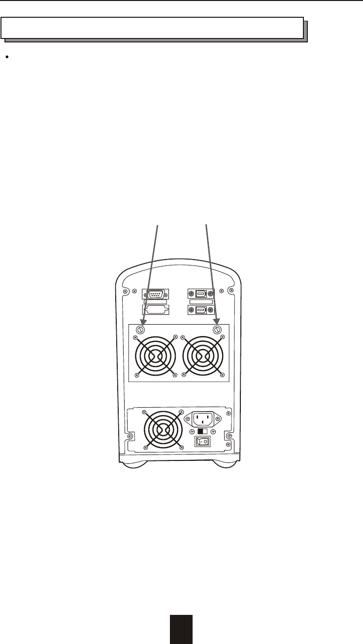
Host PortTerminal Port
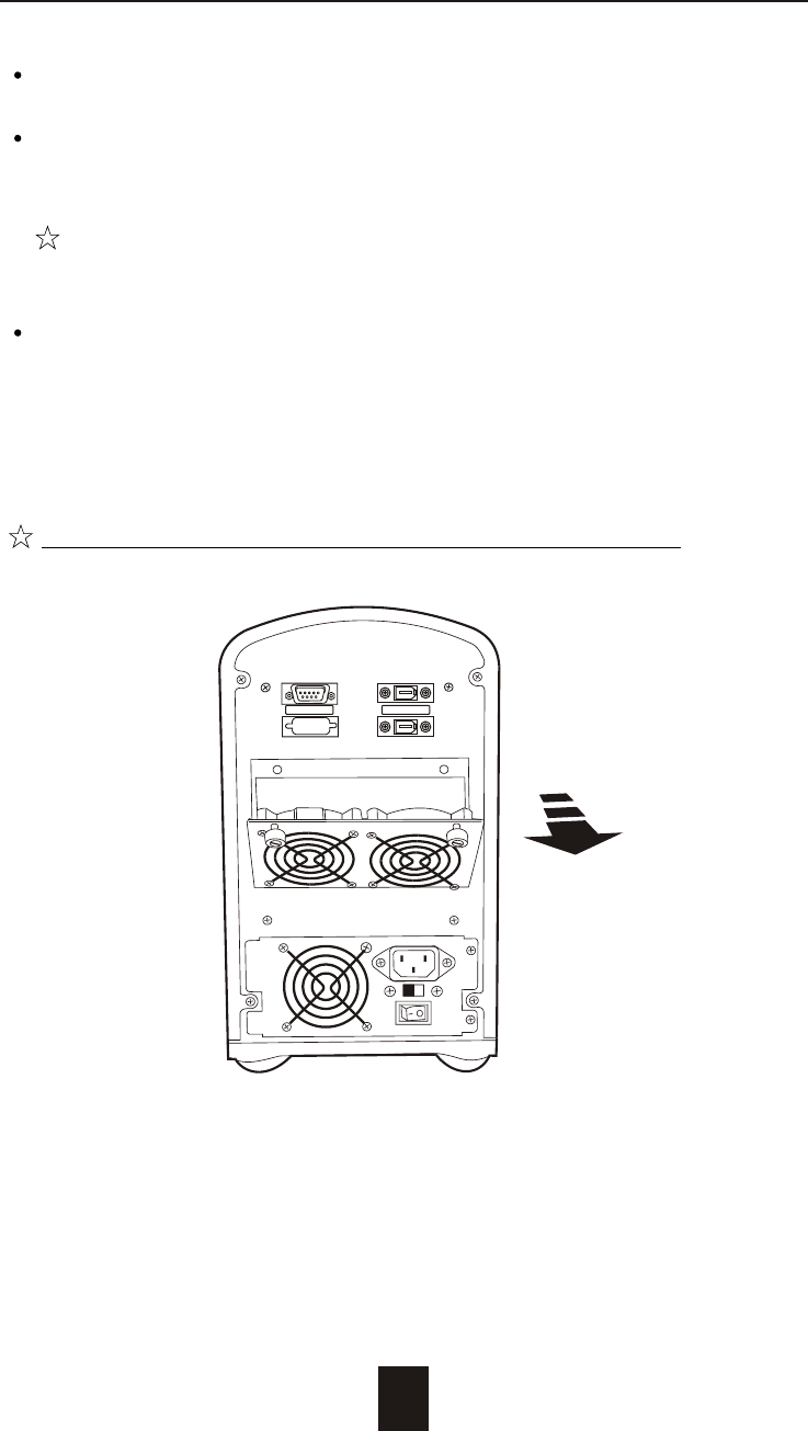
Removing / Installing Cooling Fans
Unscrew the Fan door and open the door.
: Be careful , the high speed rotating fans may harm
you. Don't touch the rotating Fans, If necessary,
Unplug the Fan power connector first.
! Caution
5-6
Hot Swap
Unscrew Here !
Figure : Swap cooling Fan ( Unscrew )
Unplug the Fan connector
Unscrew the faulty cooling fan and replace with a
good one
Important ! The cooling fan's air flow must point to the fan
door, please refer to the label on the cooling fan.
Plug in the fan connector, close the fan door
and screw it in
! Caution : The cooling fan will rotate immediately when you
plug in the fan power connector.
The Cooling Fan will only fit in one orientation.
Hot Swap
Figure : Swap Cooling Fan ( swap with a new Fan )
5-7
Host PortTerminal Port

A-1
Appendix
Microprocessor Intel i960RM RISC processor
Cache Memory 64MB*
Maximum 512MB
DRAM Slots One
Module Type 144 Pin DIMM
DRAM Type SDRAM
DRAM Speed PC100/133
Parity Non-Parity
Read Cache Read-Ahead
Write Cache Write Back*
Stripe Size Variable ( 8 ~ 128KB )
Firmware Flash EEPROM ,256K x 8
Hardware XOR Accelerate Build-In
IEEE 1394 I/O Processor TI TSB43AB22
Serial Port 1x RS232 (Asynchronous) Port
Ba ud Rate 115,200 (Bits Per Second)
Da ta Bits 8
Sto p Bit 1
Pari ty None
RAID Levels 0 , 1 , 0+1, 3 or 5
Data Transfer Rate Up to 400Mbits
Interface : Host Channel 1* IEEE 1394A Firewire
Disk Channels 4* EIDE ATA-100
Technical Specifications

A-2
Drives Hot Swap, User Replaceable
Up to Four 3.5" drives ( 1" height )
Maximum Fault >480 GB
Tolerant Capacity
Drive MTBF >1,000,000 hrs
Host Requirement Host Independent
Operating Systems O/S Independent and Transparent
Data Rebuild Automatic Data Regeneration
LCD Display Panel 2 x 16 Characters
Cooling Fans 6 cm Ball Bearing Fan
2 Fans
Power Supply Capacity 200W
AC Input Voltage 115 / 230V ( +/10% ) , 60/50 Hz
Environmental
Relative Humidity 10% to 85% Non-condensing
Temperature Operating : 5 ~ 40
Storage : -25 ~ 60
Safety testing Under apply UL, CE and FCC Class B
Dimensions 165mm(W) * 295mm(D) * 280mm(H)
Weight 7 kgs ( W/O Disk Drive )
" * " Default Settings
*** Various trademarks belong to their respective owners.
Appendix