Maxtronic Co INDY-2400 Disk Array User Manual Indy2400 Ch5
Maxtronic International Co Ltd Disk Array Indy2400 Ch5
Contents
users manual 6

Chapter 5 : " Hot Swap "
This chapter explains how to remove and install the "Hot-Swap" parts
without interrupting the data access while the disk array is on.
The "Hot-Swap" parts include :
Hard Disk Drives
Redundant Power Supply Units
Cooling Fans
Follow the steps below and refer to the diagrams to remove and
install the "Hot-Swap" parts.
5-1
Hot Swap
5-2
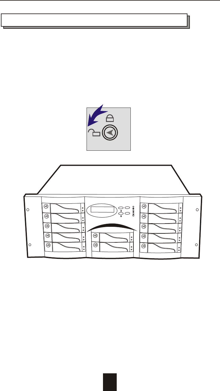
Removing / Installing Hard Disk drives
a. Unlock the HDD tray
(When a HDD error occurs, the HDD LED indicator lights up "RED")
Figure : Swap HDD ( Unlock )
ESC
Enter
5-3
Hot Swap
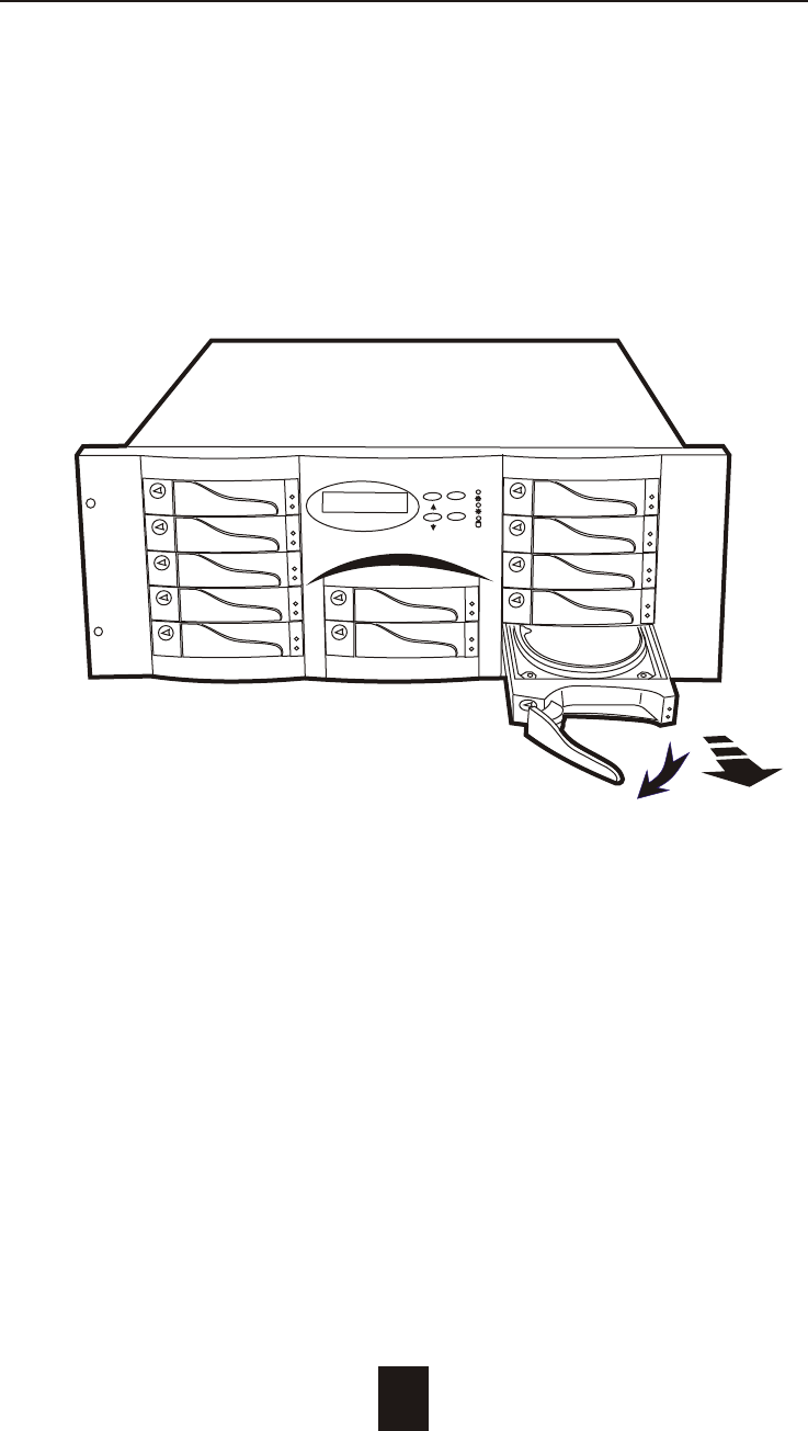
b. Gently pull-out the HDD tray
Figure : Swap HDD ( Pull-out )
ESC
Enter
Hot Swap
5-4
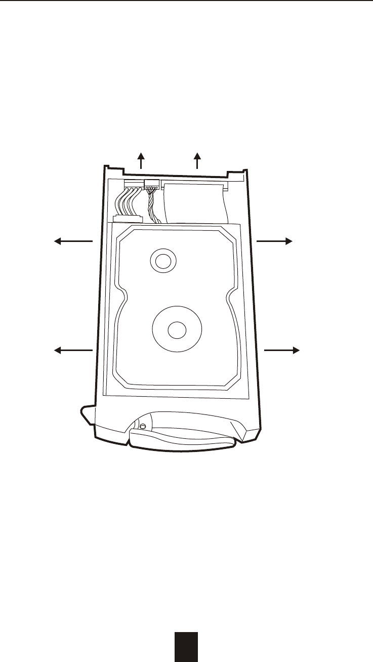
c. Unscrew and unplug the cables
Figure : Swap HDD ( Unplug cables )
Unscrew
Unplug Cables
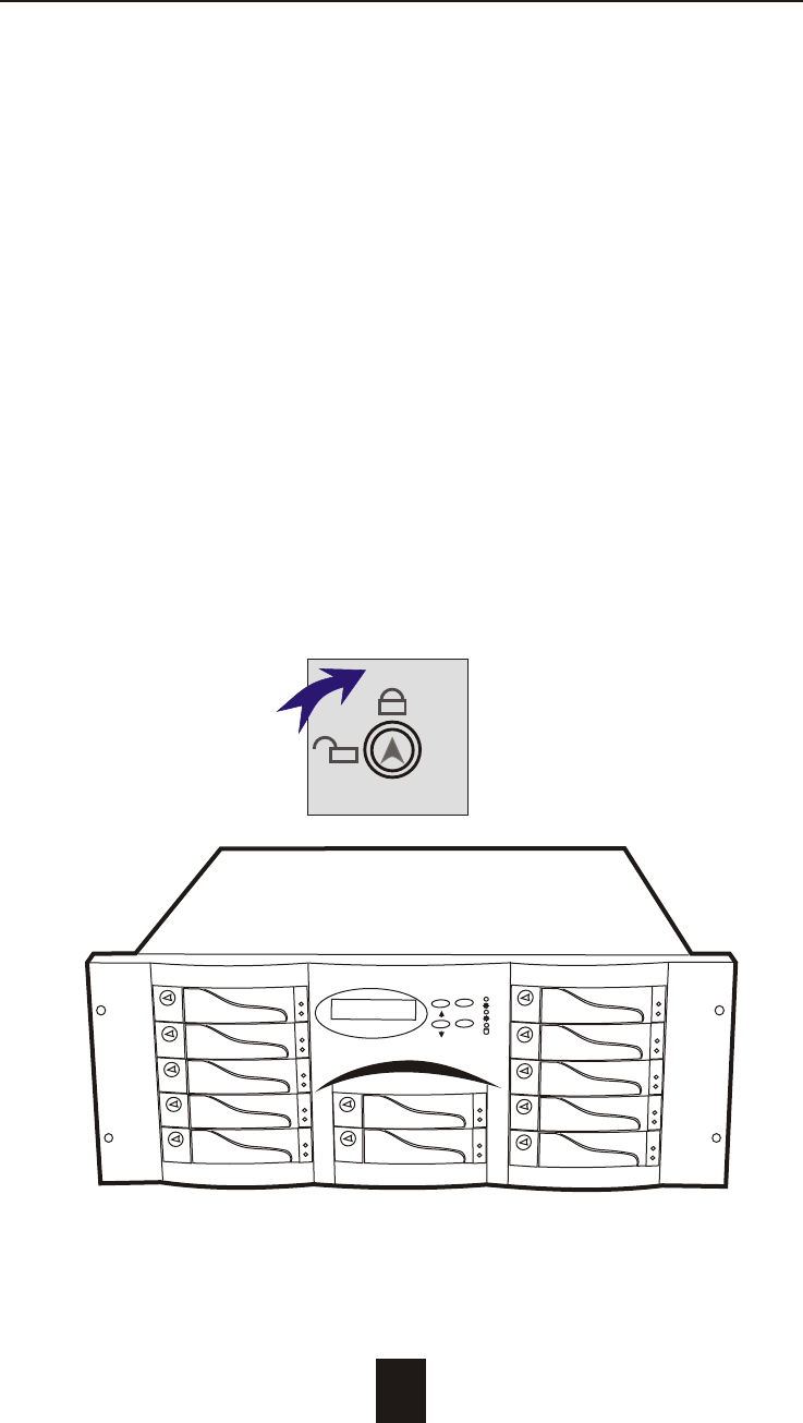
Figure : Swap HDD ( Lock Up )
Hot Swap
5-5
d. Replace with a new Hard Disk Drive
It must be same capacity or greater than the faulty drive, if you
replace with a Hard disk Drive of insufficient capacity, the Disk
Array's built-in buzzer will sound and the intelligent Auto-Rebuild
function will not be started.
* For best performance, we recommend you swap with an
identical Hard Disk Drive.
e. Gently Slide-in the HDD tray and lock up to start
the Auto-Rebuild
When you have installed the replacement disk drive, screw in all
the screws and plug in the cables, you may now gently slide in
the HDD tray into the chassis and lock up it.
* Data Auto-Rebuild will be started automatically when you lock
up the HDD tray.
ESC
Enter
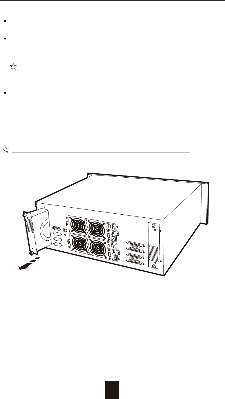
Removing / Installing the Redundant P/S Unit
There are two LED indicators on the front panel which display the
status of the redundant power supplies. While the power supply
is working properly the two LED indicators light up " Green ", if any
one of them fail, the LED indicator will go off and the redundant
power supply buzzer alarm will sound.
When you need to replace the redundant power supply unit ,
refer to the redundant power supply status LED indicator on the
front panel to find the failed power supply unit and follow these
steps to swap it.
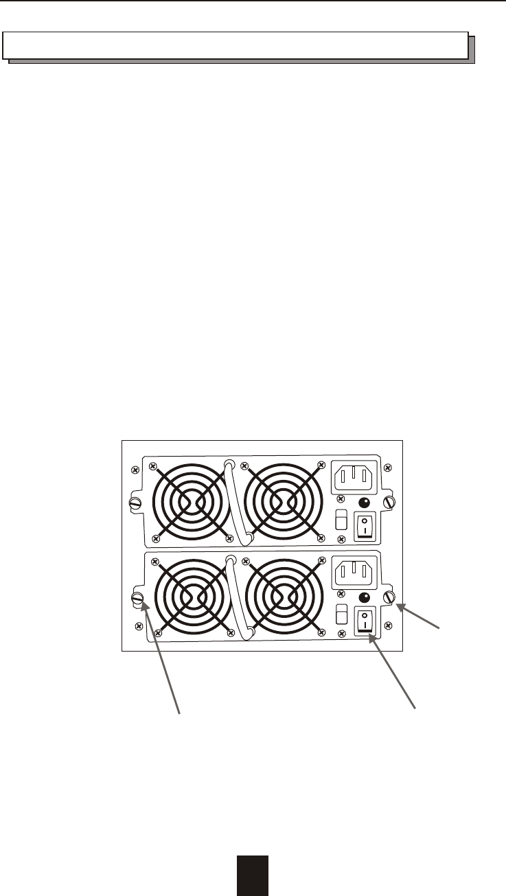
a. Unscrew the faulty unit
(For Safety reasons, you should switch off the faulty unit's
power switch)
5-6
Switch off
Unscrew
Hot Swap
Figure : Swap P/S unit ( Unscrew )
Unscrew
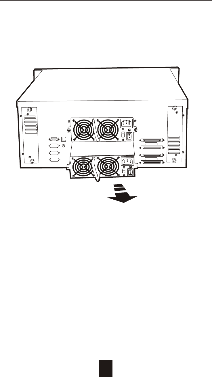
b. Replace with a new power supply unit
5-7
Hot Swap
Figure : Swap P/S unit ( swap with a new unit )
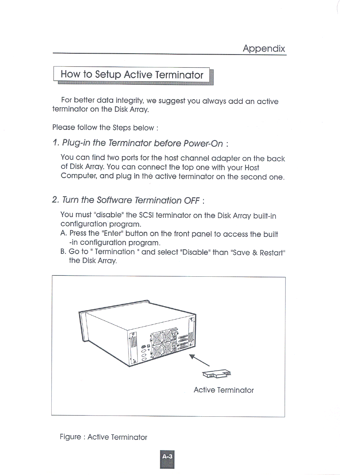
Host Port 1
Host Port 2
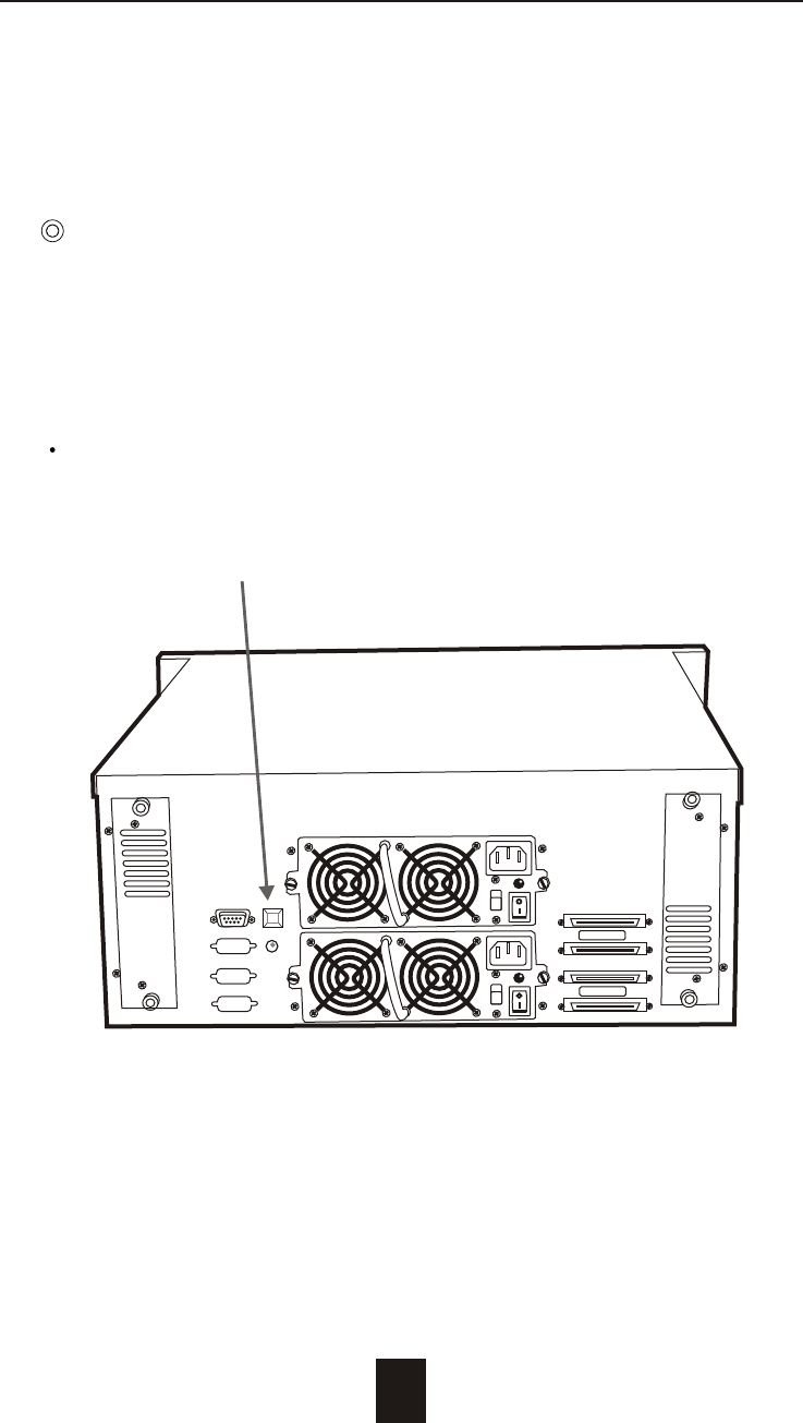
c. Press the Power Supply Alarm Reset switch
When you replace a new power supply unit, you should then
push the power supply reset switch to stop the buzzer alarm and
link the two power supply units together.
The new power supply unit will link with the other unit
immediately and will start working after you press the power
supply reset switch, and the buzzer warning noise will stop.
Reset from the rear panel
5-8
Hot Swap
Reset Here
Host Port 1
Host Port 2
Host Port 1
Host Port 2
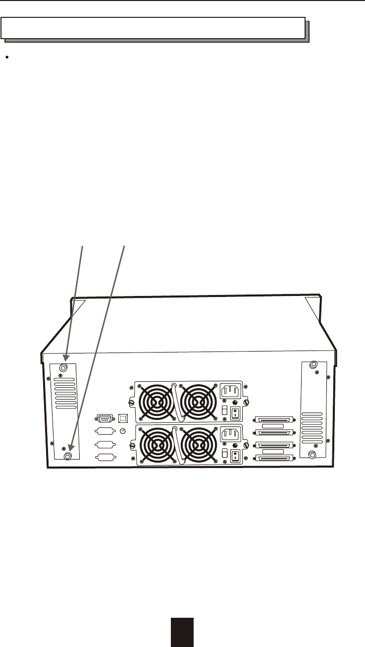
Removing / Installing Cooling Fans
Unscrew the Fan door and open the door.
: Be careful , the high speed rotating fans may harm
you. Don't touch the rotating Fans, If necessary,
Unplug the Fan power connector first.
! Caution
5-9
Hot Swap
Unscrew
Figure : Swap cooling Fan ( Unscrew )
Unplug the Fan connector
Unscrew the faulty cooling fan and replace with a
good one
Important ! The cooling fan's air flow must point to the fan
door, please refer to the label on the cooling fan.
Plug in the fan connector, close the fan door
and screw it in
! Caution : The cooling fan will rotate immediately when you
plug in the fan power connector.
The Cooling Fan will only fit in one orientation.
5-10
Hot Swap
Figure : Swap Cooling Fan ( swap with a new Fan )

A-1
Appendix
Microprocessor Intel i80303 (64-bit RISC processor)
Cache Memory 128MB*
Maximum 512MB
DRAM Slots One
Module Type 144 Pin DIMM
DRAM Type SDRAM
DRAM Speed PC100/133
Parity Non-Parity
Read Cache Read-Ahead
Write Cache Write Back*
Firmware Flash EEPROM ,256K x 8
SCSI I/O Processor LSI SYM53C1010
Serial Port 1x RS232 (Asynchronous) Port
Ba ud Rate 115,200 (Bits Per Second)
Da ta Bits 8
Sto p Bit 1
Pari ty None
RAID Levels 0 , 1 , 0+1, 3 or 5
Data Transfer Rate Up to 160MB/s (Synchronous)
SCSI ID Assignment 0 ~ 14 ( 0* )
Tagged-command queuing Up to 255 simultaneous data
requests
Technical Specifications

A-2
Interface : Host Channel 2* Ultra 160 LVD SCSI (68 pin)
Disk Channels 12* EIDE ATA-100
Drives Hot Swap, User Replaceable
Up to Twelve 3.5" drives ( 1" height )
Maximum Fault >1TB
Tolerant Capacity
Drive MTBF >1,000,000 hrs
Host Requirement Host Independent
Operating Systems O/S Independent and Transparent
Data Rebuild Automatic Data Regeneration
LCD Display Panel 2 x 16 Characters
Cooling Fans 12cm DC-Blowe r
2 Fans
Power Supply Capacity Dual 450W Independent Power
Supplies
AC Input Voltage 115 / 230V ( +/10% ) , 60/50 Hz
Environmental
Relative Humidity 10% to 85% Non-condensing
Temperature Operating : 5 ~ 40
Storage : -25 ~ 60
Safety testing Under apply UL, CE and FCC Class B
Dimensions 483mm(W) * 500mm(D) * 176mm(H)
Weight 19.5 kgs ( W/O Disk Drive )
" * " Default Settings
*** Various trademarks belong to their respective owners.
Appendix

FCC (applies in the U.S. and Canada)
This equipment has been tested and found to comply with the
limits for a Class B digital device, pursuant to Part 15 of the FCC
Rules. These limits are designed to provide reasonable
protection against harmful interference when the equipment is
operated in a residential installation. This equipment generates,
uses, and can radiate radio frequency energy and, if not
installed and used in accordance with this user's guide, may
cause harmful interference to radio communications. However,
there is no guarantee that interference will not occur in a
particular installation. If this equipment does cause harmful
interference to radio or television reception, which can be
determined by turning the equipment off and on, the user is
encouraged to try to correct the interference by one or more of
the following measures:
Warning and Certifications
This device is in conformity with the EMC
* Reorient or relocate the receiving antenna.
* Increase the separation between the equipment and receiver.
* Connect the equipment into an outlet on a circuit different
from that to which the receiver is connected.
* Consult the dealer or an experienced radio/TV technician for
help.
This device complies with Part 15 of FCC Rules. Operation is
subjected to the following two conditions:
1) this device may not cause harmful interference, and
2) this device must accept any interference received, including
interference that may cause undesired operation.
Use only shielded cables to connect I/O devices to this equipment.
You are cautioned that changes or modifications not expressly
approved by the party responsible for compliance could void
you authority to operate the equipment.
Warning: