Maxtronic Co INDY2230 Disk Array User Manual ID2230
Maxtronic International Co Ltd Disk Array ID2230
UserManual.wiki
>
Maxtronic Co
>
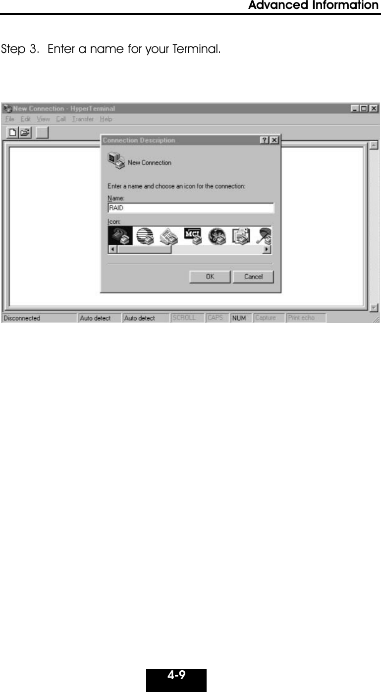
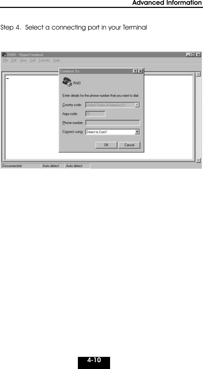
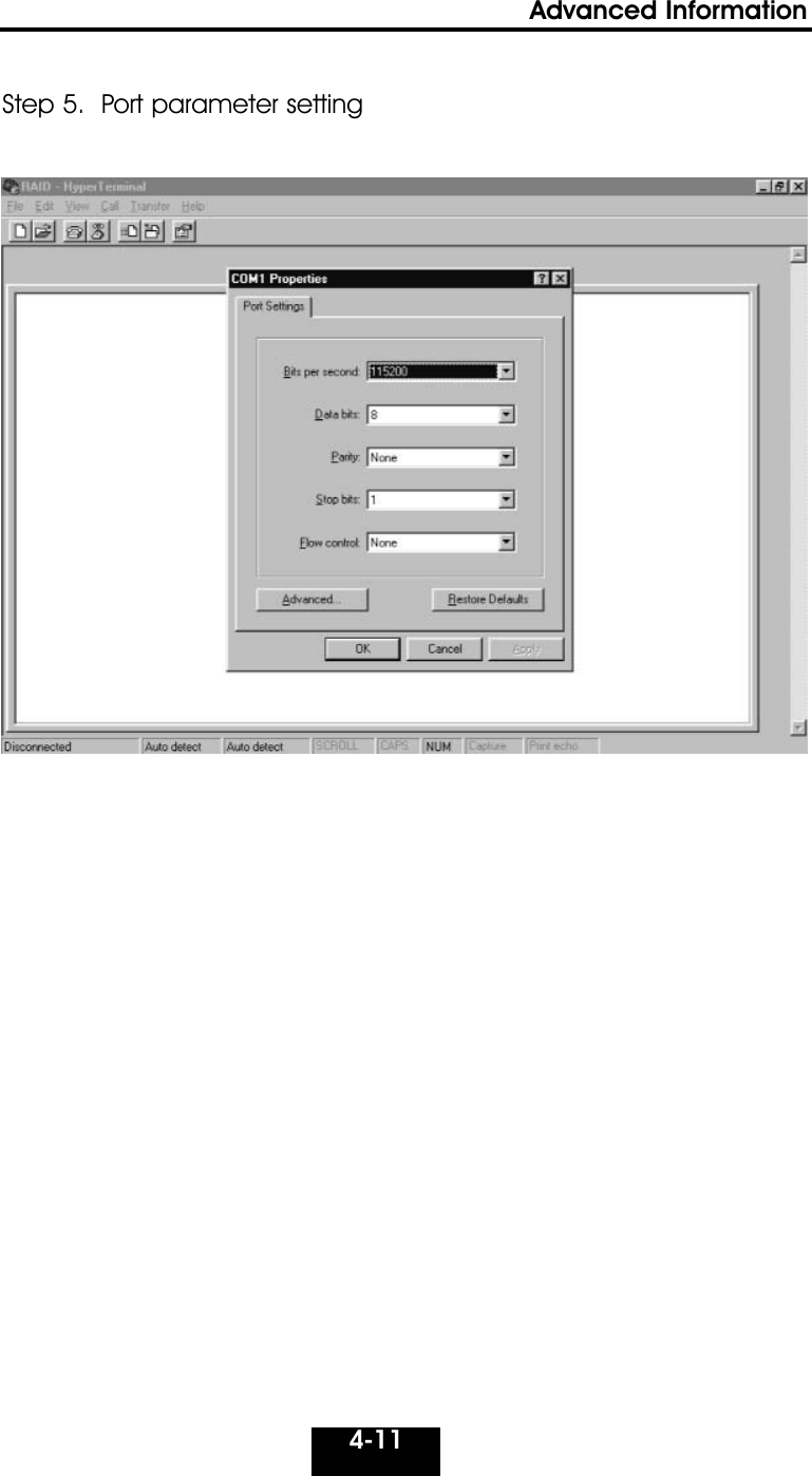
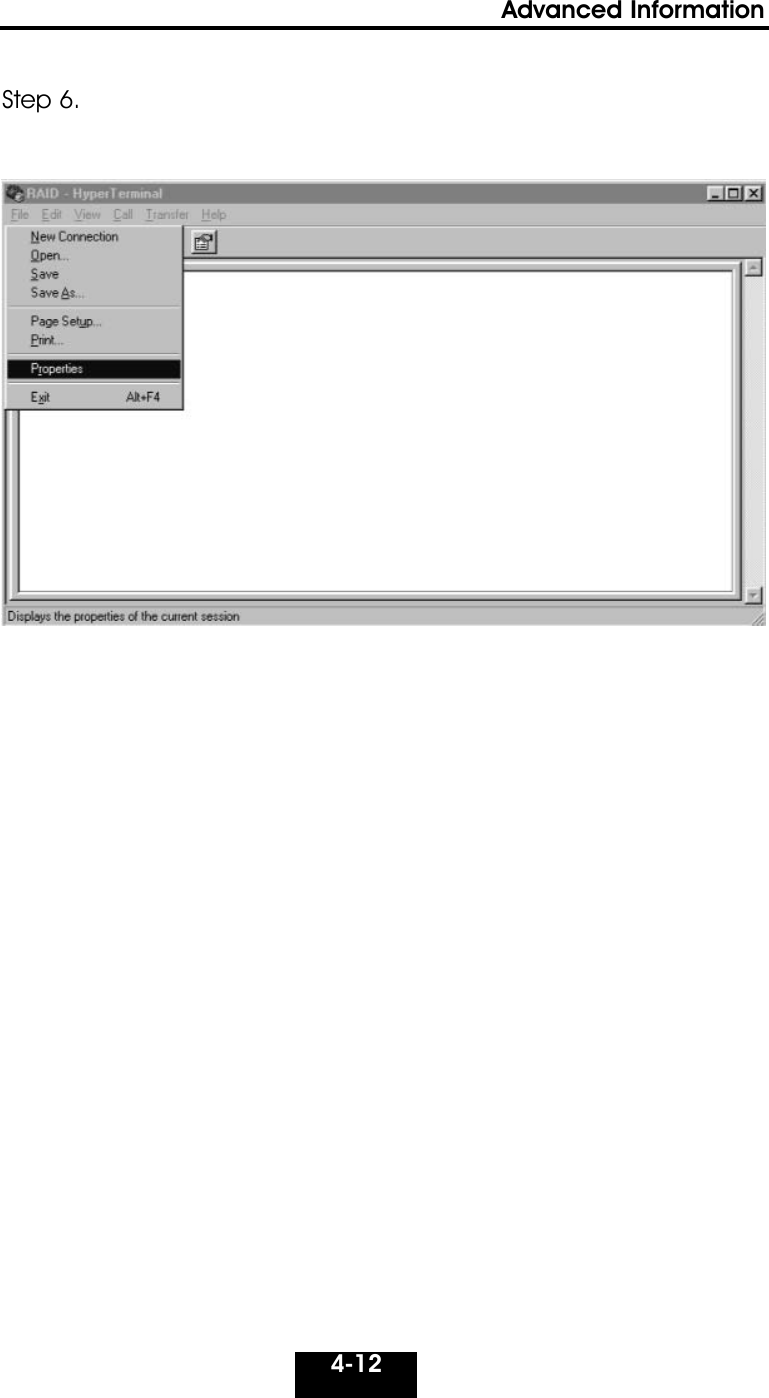
INDY2230 User Manual
users manual
Navigation menu
Upload a User Manual
Namespaces
Wiki Guide
HTML
PDF
Info
Views
User Manual
Discussion / Help
Navigation