Medex XL20-10MED XL 20 AND XL10 DIGITAL TRANSMITTER RETROFIT KIT User Manual Are You suprised

Medex, LLC XL 20 AND XL10 DIGITAL TRANSMITTER RETROFIT KIT Are You suprised

Contents

User Manual File 2 of 3

 CADCO S Y S T E M S B R O A D B A N D    E Q U I P M E N T      Operating Manual  for the  P-379 Agile Processor  System M/N         2363 Merritt Drive • Garland, Texas 75041 Phone 972-271-3651 • FAX 972-271-3654 • 800-877-2288
Table of Contents   Table of Contents        2  Important Notices       3  Suggestions for Headend Racking and Maintenance    4  Features and Options       5-6  Operating Instructions       7-8                            2
Important Notices  Shipping Loss or Damage Before signing the Common Carrier’s delivery receipt, count the number of cartons and inspect each for visible damage.  If the number of cartons does not agree with the receipt or there is damage, make note of these discrepancies on all copies of the receipt before signing.  Immediately unpack the equipment and inspect for concealed damage.  If damage is found, notify the carrier immediately.  We suggest you keep the shipping carton and packaging material should the equipment ever need to be returned.  After filing you claim, notify CADCO for assistance on repair or replacement disposition.  CAUTION – Unauthorized Repair Unauthorized repair, modification or disassembly during the warranty period may cancel the warranty.  Should field repairs or modifications be desired, CADCO technicians may be able to provide helpful suggestions, saving you both time and money.    Notice of Proprietary Data and Changes Data, drawings, designs represented and all other material contained herein are the proprietary property of CADCO Systems, Inc., and may not be reproduced or duplicated in any form without written authorization by CADCO Systems, Inc.  All material is subject to change without notice or obligation.  Equipment Return Should you desire to return the equipment for service, please call CADCO prior to shipping.  Enclosing as much information as possible on the reason for return and the work desired will expedite service and help to insure your satisfaction.  If possible, pack the equipment in the original carton and materials.  If the original packaging material is no longer available, pack the equipment in cushioning material sufficient to provide a minimum of 1.5 inches separation between the carton and the equipment.  No Return Authorization number is required.  Include your return address, telephone number and method of return shipment.  Ship the equipment prepaid to the address in this manual.  Reasons for using CADCO Factory Service:    CADCO services exclusively CADCO equipment     Designed and manufactured your CADCO equipment    Knows CADCO equipment better than any other service provider    Technicians are trained on all CURRENT and PAST technical product information    Technicians use specialized testing and alignment tools designed for CADCO equipment    Technicians may often help with a specialized application    Toll-free factory sales and service hotline   Factory service rates are very competitive and in many cases less expensive than non-factory service stations  Guarantees factory service for two years  Is known for fast, friendly customer service  3
Suggestions for Headend Racking and Maintenance  For prolonged equipment life and operating stability, the following recommendations are made:  •  All headends should be installed in an environmentally controlled dust-free room having a nominal temperature of 80°F (26°C) and 60% humidity.  The room should be protected from rodents and insect pests.  •  All equipment should be mounted in standard equipment racks or cabinets  •  All equipment should be rack spaced at one panel height, 1.75 inches (4.44cm).  There should be nothing between the equipment preventing air circulation.  •  Please make certain headend wiring and current capacity has adequate safety margins.  Never cascade AC powering strips.  Use separate outlets.  If AC power is subject to fluctuation we recommend a constant voltage transformer be used.  Beware of ground loops and be certain all wiring is bonded and properly grounded.  Consult a code book as needed.  •  All equipment racks should be electrically bonded together and earth grounded  •  All equipment interconnecting RF cables should be a minimum of double shielded and quad shielded is recommended.  Poorly shielded cable causes cross-modulation picture degradation between equipment.  •  Always use the coax connector intended for the coaxial cable used.  Be certain it is installed as recommended by the manufacturer.  Connectors should be RFI shielded.  •  RF Input and RF Output cables should be on opposite sides of the equipment rack.  Never bundle input and output RF cables together.  •  Operate each modulator and processor at the RF output level recommended.  If it is necessary to reduce the RF Output level, always operate the equipment as recommended and reduce the RF  •  Equipment RF test points are only relative indicators of the actual RF output level.  All RF operating level measurements should be made at the RF Output of each unit.  •  When the headend is initially placed in service, create a record of all operating parameters for each channel’s equipment.  Referring to these records during routine maintenance provides a helpful record of operating changes.    4
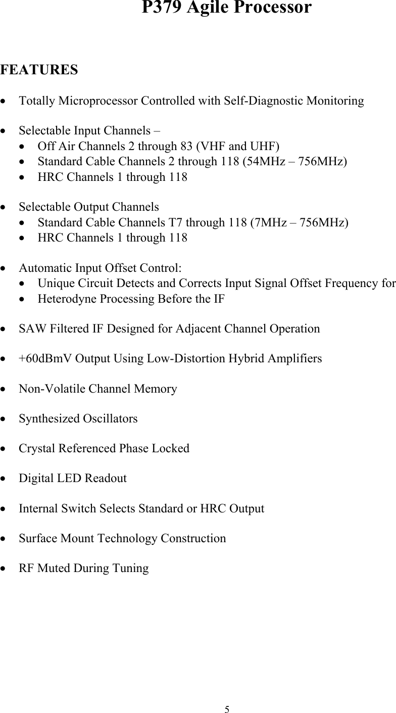
P379 Agile Processor   FEATURES  •  Totally Microprocessor Controlled with Self-Diagnostic Monitoring  •  Selectable Input Channels – •  Off Air Channels 2 through 83 (VHF and UHF) •  Standard Cable Channels 2 through 118 (54MHz – 756MHz) •  HRC Channels 1 through 118   •  Selectable Output Channels •  Standard Cable Channels T7 through 118 (7MHz – 756MHz) •  HRC Channels 1 through 118   •  Automatic Input Offset Control: •  Unique Circuit Detects and Corrects Input Signal Offset Frequency for •  Heterodyne Processing Before the IF  •  SAW Filtered IF Designed for Adjacent Channel Operation  •  +60dBmV Output Using Low-Distortion Hybrid Amplifiers  •  Non-Volatile Channel Memory  •  Synthesized Oscillators  •  Crystal Referenced Phase Locked  •  Digital LED Readout  •  Internal Switch Selects Standard or HRC Output  •  Surface Mount Technology Construction  •  RF Muted During Tuning        5
AVAILABLE OPTIONS  •  T-Channel Input (P379T): Allows for T7-T14 Inputs as well as standard input frequencies  •  Defeatable AGC for Manual Gain Control   HRC Output Frequency Set  All CADCO frequency agile products may be set for HRC frequency output.  This feature is controlled by an internal dip switch assembly, DS-1.  The switch is located near the right front corner (with the front panel facing you) between the test point and the output converter module.  DS-1 is clearly marked on the PCB.  Switch #3 placed in the ‘OFF’ position switches the output frequency to HRC on all channels.  The switch is normally set to ‘ON’ at the factory.                            6
Operating Instructions  Model P379 Agile Processor   INTRODUCTION CADCO thanks you for purchasing the P379 Heterodyne Low-Noise Processor.  The P379 contains the latest in CATV electronics, including Synthesized Crystal Referenced Phase Locked Oscillators, SAW filtered IF, Hybrid Amplifiers and Microprocessor Control.  Now in addition to these features, the new P379 (US Version) contains Automatic Input Offset, which removes input offsets inherent to Off-Air (0, +10KHz), Standard Cable (0, +12.5, +25KHz) and HRC Cable (0.3 KHz master oscillator offset).  SETUP AND OPERATION P379 Processor  •  Connect the input to a signal source, such as a cable drop or antenna.  The recommended input level for best performance is 0 to +10 dBmV (+60 to +70 dBuV).  Connect the output to a 75 Ohm load, normally a channel combiner.  A Hybrid Combiner is strongly recommended for flat response and maximum isolation between channels.  •  The Automatic Input Offset feature automatically removes any input offset, while the microprocessors select the proper FCC offset for the output channel.  •  Connect to a proper AC electrical source as indicated on the back of the unit.  Observe the front panel Display Window while power is applied; all elements of the displays will be turned on momentarily as a display test.  The following numbers displayed after the LED test will be the microprocessor software version, the internal option dip switch settings and finally the last frequency tuned.  After a moment, the Lock Detect LED will illuminate.  The unit is now ready for operation.  •  The desired input and output channel of operation is selected by the front panel CHANNEL SELECT toggle switch.  If you require a channel other than the one currently displayed, move the toggle switch up or down to cycle through the channels until the channel you are selecting is displayed.  To prevent accidental channel changing, the toggle switch must be held up or down for a few seconds before actual channel switching will occur.  It is normal for the FREQUENCY LOCK LED to be off during and for a few seconds after changing channels.  The RF OUTPUT is muted when the FREQUENCY LOCK LED is off.  This insures that existing channels on the cable system are not interfered with during the channel selection process.  FCC offsets (US Versions) are microprocessor controlled and fully automatic for both Standard and HRC Channels.   7
 8•  Using a Field Strength Meter or Spectrum Analyzer connected to the rear panel RF OUTPUT connector, adjust the front panel OUTPUT LEVEL control to the desired level.  The recommended output level is between +55dBmV (+115dBuV) and +60dBmV (+120dBuV).  •  Note:  The optimum input signal level is +10dBmV (+70dBuV) to be centered within the AGC window.  Signal input levels less than 0dBmV (+60dBuV) may require an antenna-mounted preamplifier.  Remember, the P379’s AGC will increase gain for full output, but with inadequate input signal level, the Signal to Noise ration will suffer.  •  When in the Off-Air position for INPUT SOURCE, observe the Aural Carrier level on a Field Strength Meter or Spectrum Analyzer and adjust the AURAL CARRIER LEVEL control to the desired Visual to Aural Carrier level ratio.  Normal operation of the Aural Carrier is 13 to 17 below the Visual Carrier.  When switching to either of the cable frequency plans, the internal aural carrier attenuator drops automatically from 6 to 0dB, since Cable Aural signals have been preset down at the headend.  Readjustment when switching between frequency plans may be desired.  •  The model P379 processor accepts and passes through television broadcast stereo.  •  To use the T-Channel Input Option (P379T Agile Processor), move the T-Channel switch located on the back panel to the ‘ON’ position.  The green T-Channel Indicator LED, located on the front panel, will light up when in the “T” Band.  When the T-Channel switch is on, only the “T” band may be used.      IMPORTANT  CADCO power supplies are designed so that under certain power line or heat buildup conditions the unit shuts off.  An indicator would be no RF output, but the POWR LED remains on.  If this occurs, unplug the power cord and wait two minutes before re-powering.  Upon applying power, you should again have RF output.  If not, or should the unit return to shutdown mode, please contact CADCO for assistance.  CADCO highly recommends a 1.75 inch air circulation space between any rack mounted equipment.

Navigation menu