MediaTek RT3290 802.11b/g/n 1T1R Combo Card User Manual RT3290 Installation guide
MediaTek Inc. 802.11b/g/n 1T1R Combo Card RT3290 Installation guide
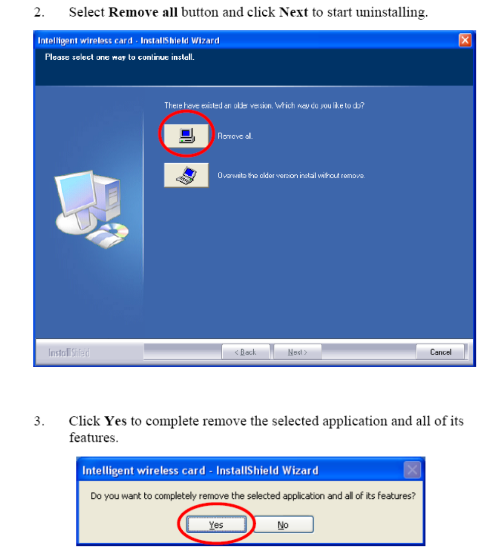
MediaTek >
Contents
User Manual.pdf

802.11b/g/n 1T1R Combo Card
RT3290
User’s Manual
Hardware Quick Installation Guide
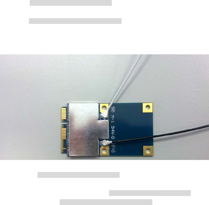
Installing the Wireless Mini PCI Express Module
1. Power down the computer.
2. Plug the Wireless PCI Express Minicard Module board to motherboard minicard slot
3. Connect 2 external antennas used I-PEX connector for WiFi antenna.
4. Power on the computer.
Un-installing the Wireless Mini PCI Express Module
1. Power down the computer
2. Removed 2 external WiFi antennas from the Wireless Mini PCI Express Module
3. Carefully removed the Wireless PCI Express Minicard Module from the motherboard minicard slot.
4. Power on the computer.
2 external
INTRODUCTION
The 11b/g/n 1T1R WLAN Mini Card is a device that allows you connect your computer to a wireless local
area network (LAN). A wireless LAN allows your system to use wireless Radio Frequency (RF) technology to
transmit and receive data without physically attaching to the network. The Wireless protocols that come with
this product ensure data security and isolation from interference generated by other radio frequencies. This
card also allows you to take full advantage of your computer’s mobility with access to real-time information
and online services anytime and anywhere. In addition, this device eliminates the bother of pulling cable
through walls and under furniture. It even allows you to place your system in locations where cabling is
impossible. Modifying and augmenting networks has never been so easy.
Wireless Network Options
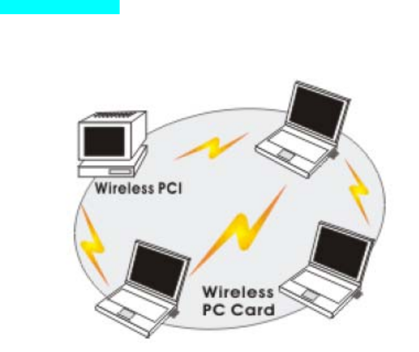
The Peer-to-Peer Network
This network installation lets you set a small wireless workgroup easily and quickly. Equipped with wireless
PC Cards or wireless PCI, you can share files and printers between each PC and laptop.
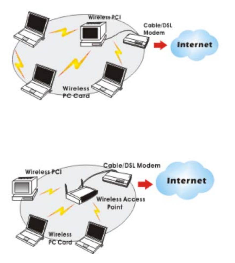
You can also use one computer as an Internet Server to connect to a wired global network and share files
and information with other computers via a wireless LAN.
The Access Point Network The network installation allows you to share files, printers, and Internet access
much more conveniently. With Wireless LAN Cards, you can connect wireless LAN to a wired global
network via an Access Point.
SOFTWARE INSTALLATION
Install the device
1. Make sure the computer is turned off. Remove the expansion slot cover from the computer.
2. Carefully slide the 11b/g/n 1T1R WLAN Mini Card into the mini PCI slot. Push evenly and slowly and
ensure it is properly seated.
3. After the device has been connected to your computer, turn on your computer. Windows will detect the
new hardware and then automatically copy all of the files needed for networking.
Install the Driver & Utility
1. Exit all Windows programs. Insert the included CD-ROM into your computer. The CD-ROM will run
automatically.
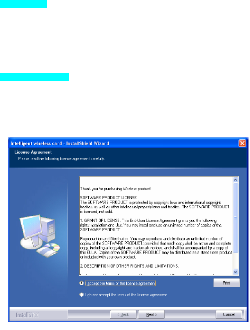
2. When the License Agreement screen appears, please read the contents and select “I accept the terms of
the license agreement “ then click Next to continue.
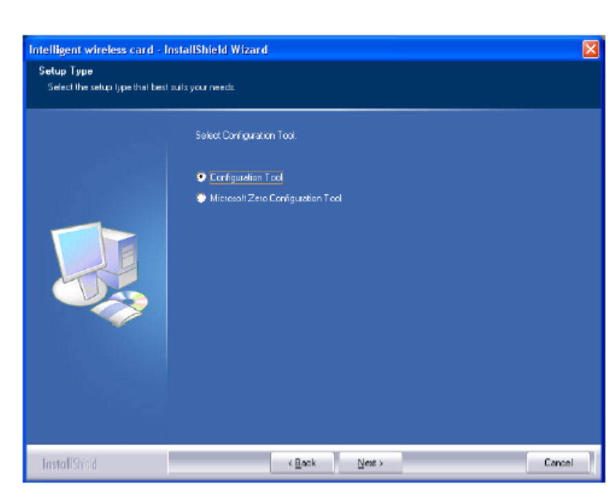
3. Select the check box to choose a Configuration Tool from the listed two choices.
- Configuration Tool: Choose to use our configuration utility.
- Microsoft Zero Configuration Tool: Choose to use Windows XP’s built-in Zero Configuration Utility (ZCU).
Click Next to continue.
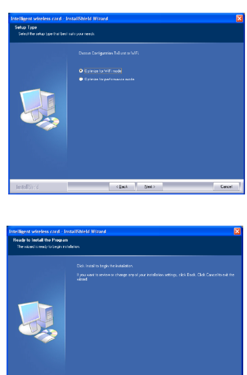
4. There are two modes for you to choose in this screen, either choose WiFi mode or performance
mode (TxBurst mode). This mode selection screen is set for the default mode shown in the utility
screen, you can still change its mode later in the utility screen. Click Next to continue.
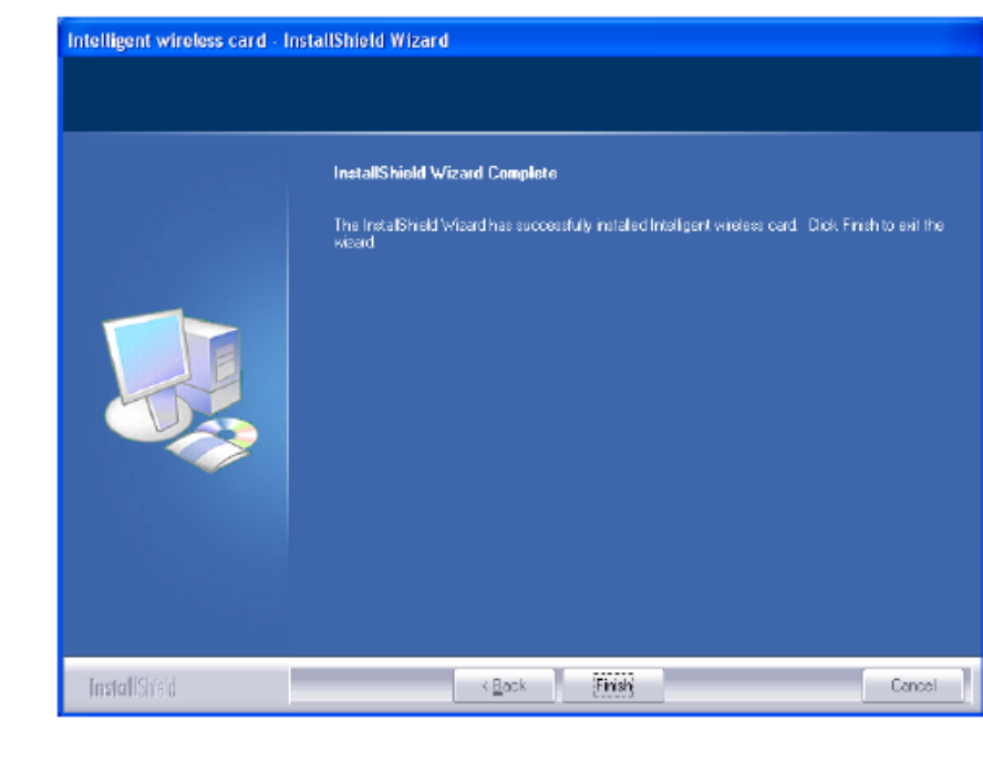
5. When you are prompted the following message, please click Install to begin the installation.
6. When the following screen appears, click Finish to complete the software installation.
HARDWARE INSTALLATION
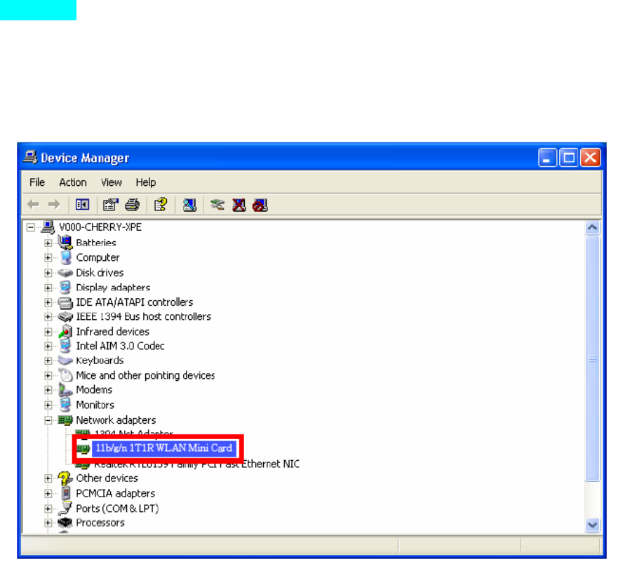
Verification
To verify if the device exists in your computer and is enabled, go to Start > Control Panel > System (>
Hardware) > Device Manager. Expand the Network Adapters category. If the 11b/g/n 1T1R WLAN Half
Mini Cardis listed here, it means that your device is properly installed and enabled.
NETWORK CONNECTION
Once the device driver is well installed, a network setting described in the following should be also
established.
In Windows 2000/ XP
1. (In Windows 2000) Go to Start Æ Settings Æ Control Panel Æ Network and Dial-up Connections
Local Area Connection Æ Properties.
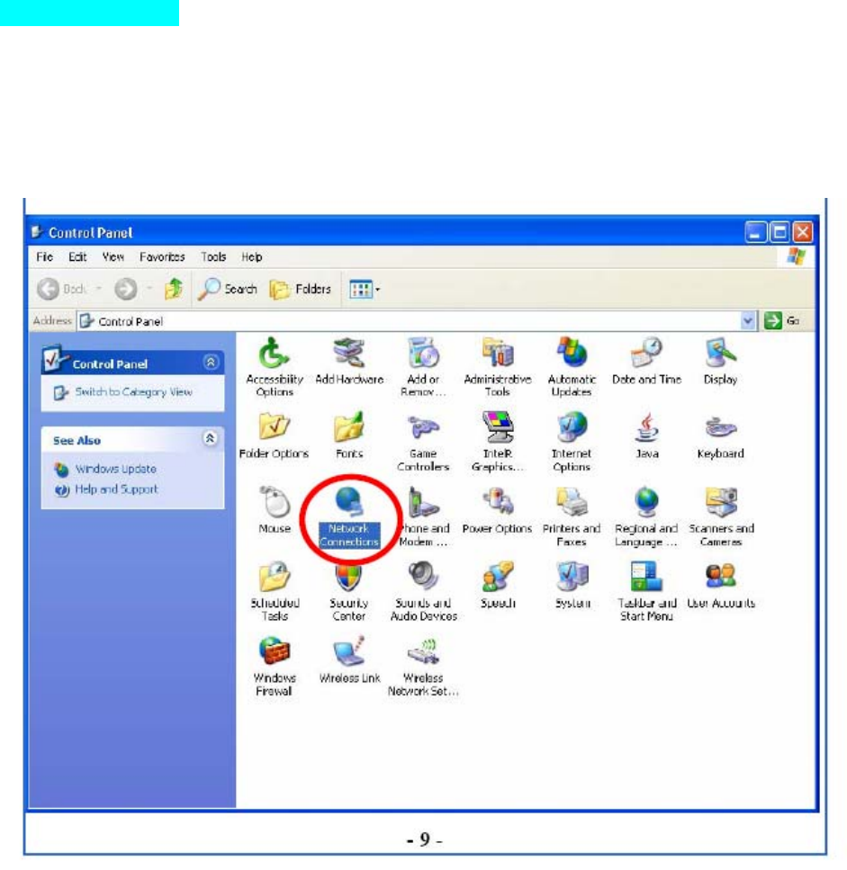
(In Windows XP) Go to Start Æ Control Panel Æ Network and Internet Connections Æ Network
Connections Æ Wireless Network Connection Æ Properties.
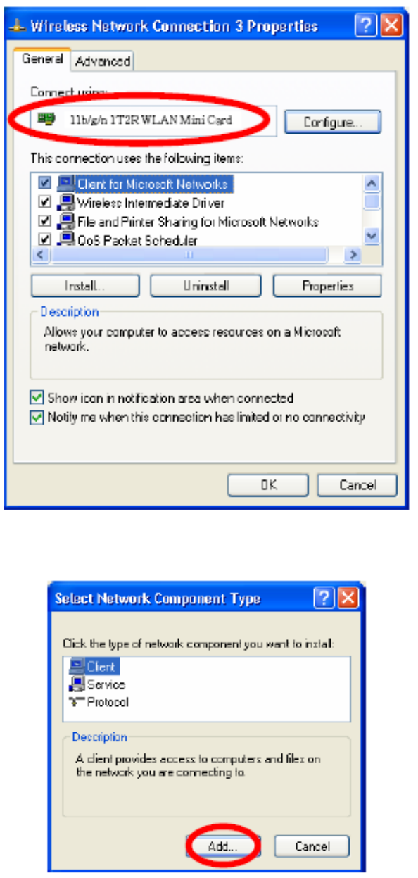
2. Make sure that all the required components are installed.
3. If any components are missing, click on the Install… button to select the Client/Service/Protocol
required. After selecting the component you need, click Add… to add it in.
4. For making your computer visible on the network, make sure you have installed File and Printer Sharing
for Microsoft Networks.
IP Address
Note: When assigning IP Addresses to the computers on the network, remember to have the IP address for
each computer set on the same subnet mask. If your Broadband Router use DHCP technology, however, it
won’t be necessary for you to assign Static IP Address for your computer.
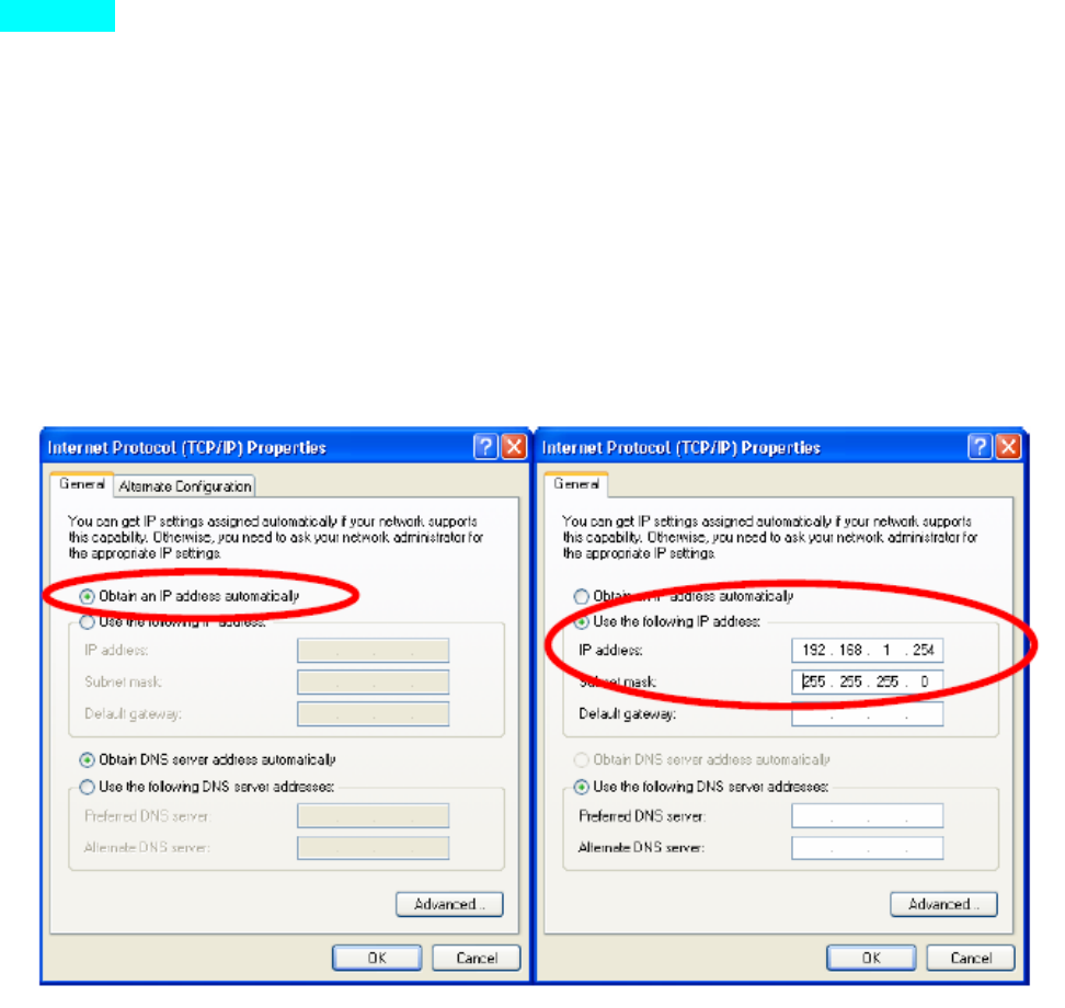
1. To configure a dynamic IP address (i.e. if your broadband Router has the DHCP technology), check the
Obtain an IP Address Automatically option.
2. To configure a fixed IP address (if you broadband Router is not DHCP supported, or when you need to
assign a static IP address), check the Use the following IP address option. Then, enter an IP address into the
empty field; for example, enter 192.168.1.254 in the IP address field, and 255.255.255.0 for the Subnet Mask.
CONFIGURATION UTILITY
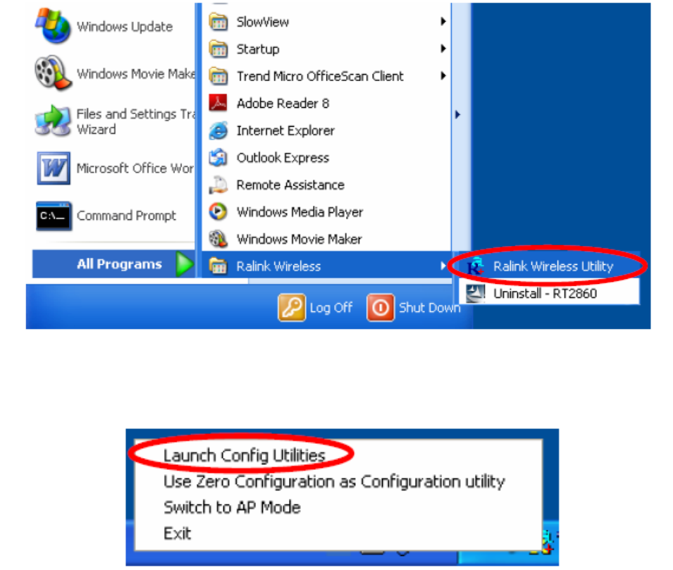
After the Wireless adapter has been successfully installed, users can use the included Configuration Utility to
set their preference. Go to StartÆ (All) ProgramsÆ Ralink Wireless ÆRalink Wireless Utility.
You can also open the Configuration Utility by double clicking the icon or right clicking to select Launch
Config Utilities.
Intelligent Wireless Utility
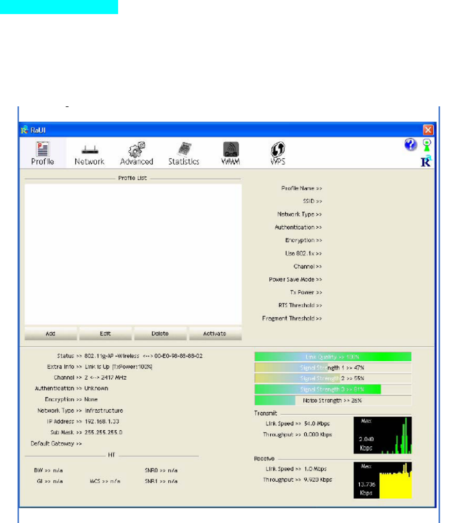
Profile
Profile can book keeping your favorite wireless setting among your home, office, and other public hot-spot.
You may save multiple profiles, and activate the correct one at your preference. The Profile manager enables
you to Add, Edit, Delete and Activate profiles.
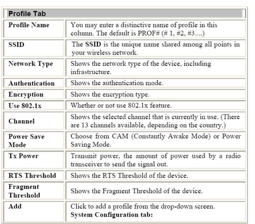
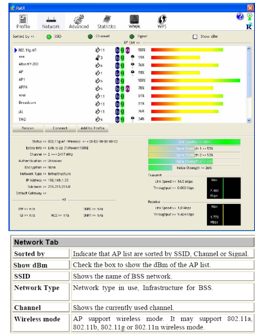
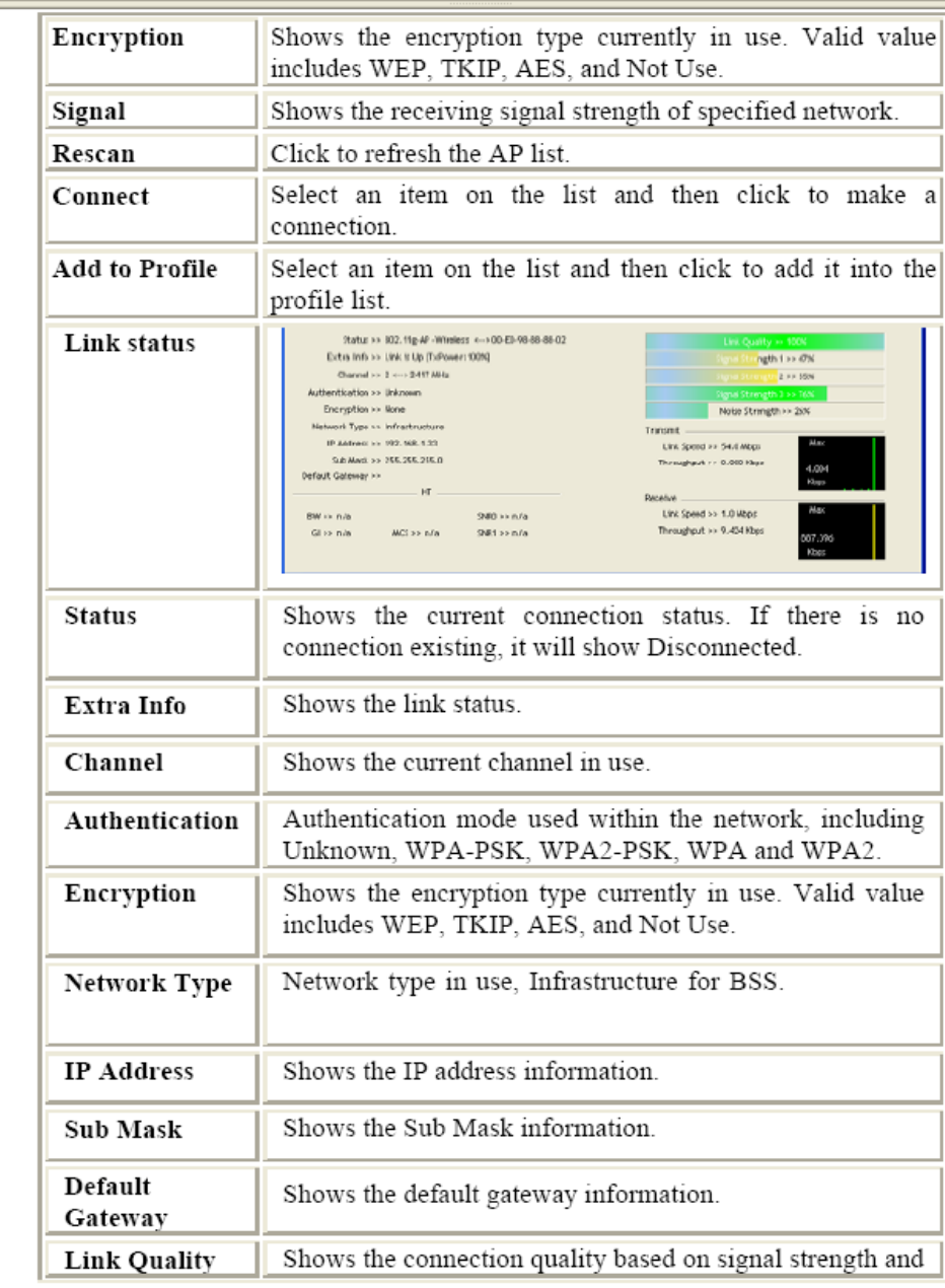
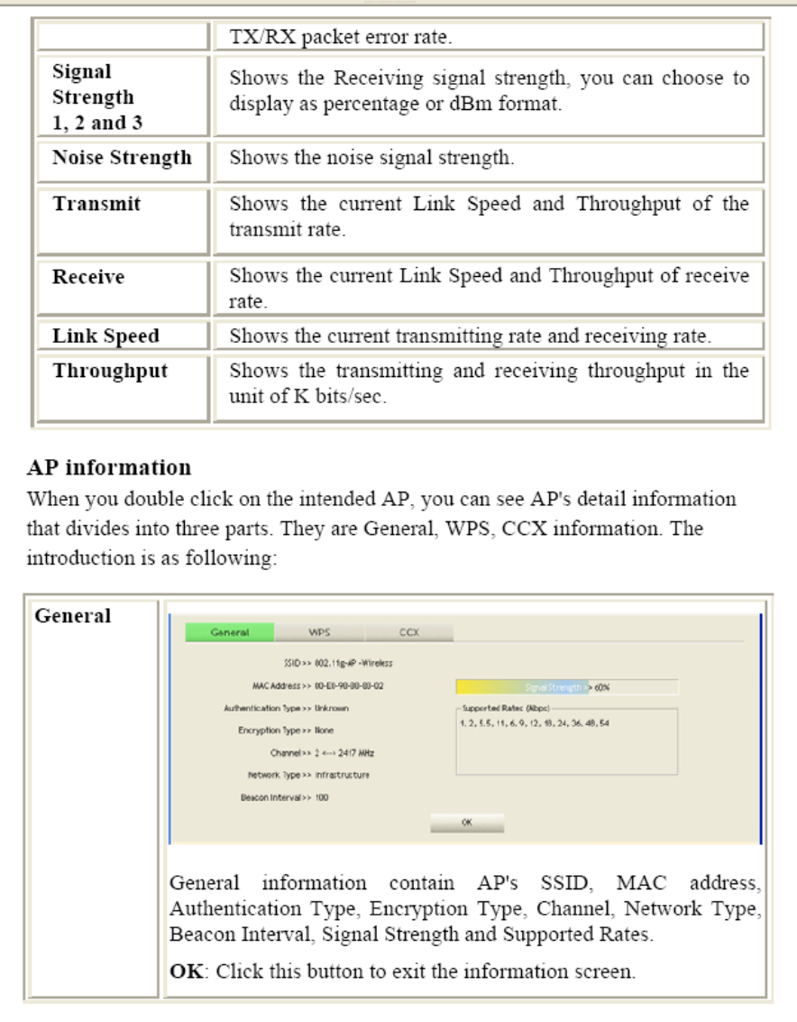
Network The Network page displays the information of surrounding APs from last scan result. The tab lists
the information including SSID, Network type, Channel, Wireless mode, Security-Enabled and Signal.

Federal Communication Commission Interference Statement
This device complies with Part 15 of the FCC Rules. Operation is subject to the following two conditions: (1) This
device may not cause harmful interference, and (2) this device must accept any interference received, including
interference that may cause undesired operation.
This equipment has been tested and found to comply with the limits for a Class B digital device, pursuant to Part 15 of
the FCC Rules. These limits are designed to provide reasonable protection against harmful interference in a
residential installation. This equipment generates, uses and can radiate radio frequency energy and, if not installed and
used in accordance with the instructions, may cause harmful interference to radio communications. However, there
is no guarantee that interference will not occur in a particular installation. If this equipment does cause harmful
interference to radio or television reception, which can be determined by turning the equipment off and on, the user is
encouraged to try to correct the interference by one of the following measures:
- Reorient or relocate the receiving antenna.
- Increase the separation between the equipment and receiver.
- Connect the equipment into an outlet on a circuit different from that
to which the receiver is connected.
- Consult the dealer or an experienced radio/TV technician for help.
FCC Caution: Any changes or modifications not expressly approved by the party responsible for compliance could
void the user's authority to operate this equipment.
This transmitter must not be co-located or operating in conjunction with any other antenna or transmitter.
Radiation Exposure Statement:
This equipment complies with FCC radiation exposure limits set forth for an uncontrolled environment. This
equipment should be installed and operated with minimum distance 20cm between the radiator & your body.
This device is intended only for OEM integrators under the following conditions:
1) The antenna must be installed such that 20 cm is maintained between the antenna and users, and
2) The transmitter module may not be co-located with any other transmitter or antenna.
As long as 2 conditions above are met, further transmitter test will not be required. However, the OEM integrator is
still responsible for testing their end-product for any additional compliance requirements required with this module
installed
IMPORTANT NOTE: In the event that these conditions can not be met (for example certain laptop configurations or
co-location with another transmitter), then the FCC authorization is no longer considered valid and the FCC ID can
not be used on the final product. In these circumstances, the OEM integrator will be responsible for re-evaluating the
end product (including the transmitter) and obtaining a separate FCC authorization.
End Product Labeling
This transmitter module is authorized only for use in device where the antenna may be installed such that 20 cm may
be maintained between the antenna and users. The final end product must be labeled in a visible area with the
following: “Contains FCC ID: VQF-RT5390”. The grantee's FCC ID can be used only when all FCC compliance
requirements are met.
Manual Information To the End User
The OEM integrator has to be aware not to provide information to the end user regarding how to install or remove this
RF module in the user’s manual of the end product which integrates this module.
The end user manual shall include all required regulatory information/warning as show in this manual.
Special note to portable usage
This module has been tested and approved for the following portable application under the specified specific
host configuration as described in this FCC/IC ID. All other host(s)/configuration(s) need a separate FCC
class II change or IC reassessment approval.
Approved portable usage host list here:
Platform
NB Name Zonda & Huayra
NB Model Zonda: TPN-C107
Huayra: TPN-C106
NB Size 15.6
Applicable antennas
ANT Set1
Ant. Brand name
Model name Peak Gain (Included Cable loss)
(dBi)
Antenna
Type
Connector Type
Chain (0)
WNC DC330014C10(81.
EL815.G54)
-2.04 PIFA
U.FL
Chain (1)
WNC DC330014C00(81.
EL815.G53)
-2.58 PIFA
U.FL
ANT Set 2
Ant. Brand name
Model name Peak Gain (Included Cable loss)
(dBi)
Antenna
Type
Connector Type
Chain (0)
WHAYU C435-520153-A
-0.60 PIFA
U.FL
Chain (1)
WHAYU C435-520152-A
1.41 PIFA
U.FL
ANT Set 3
Ant. Brand name Model name
Peak Gain (Included Cable loss)
(dBi)
Antenna
Type
Connector Type
Chain (0)
Smart
Approach
Co.,Ltd
SE-ECC50-002
-1.17 PIFA U.FL
Chain (1)
Smart
Approach
Co.,Ltd
SE-ECC50-001
0.45 PIFA U.FL
Industry Canada statement:

This device complies with RSS-210 of the Industry Canada Rules. Operation is subject to the following two conditions: (1) This
device may not cause harmful interference, and (2) this device must accept any interference received, including interference that
may cause undesired operation.
Ce dispositif est conforme à la norme CNR-210 d'Industrie Canada applicable aux appareils radio exempts de licence. Son
fonctionnement est sujet aux deux conditions suivantes: (1) le dispositif ne doit pas produire de brouillage préjudiciable, et (2) ce
dispositif doit accepter tout brouillage reçu, y compris un brouillage susceptible de provoquer un fonctionnement indésirable.
Radiation Exposure Statement:
This equipment complies with IC radiation exposure limits set forth for an uncontrolled environment. This equipment should be
installed and operated with minimum distance 20cm between the radiator & your body.
Déclaration d'exposition aux radiations:
Cet équipement est conforme aux limites d'exposition aux rayonnements IC établies pour un environnement non contrôlé. Cet
équipement doit être installé et utilisé avec un minimum de 20 cm de distance entre la source de rayonnement et votre corps.
This device is intended only for OEM integrators under the following conditions: (For module device use)
1) The antenna must be installed such that 20 cm is maintained between the antenna and users, and
2) The transmitter module may not be co-located with any other transmitter or antenna.
As long as 2 conditions above are met, further transmitter test will not be required. However, the OEM integrator is still
responsible for testing their end-product for any additional compliance requirements required with this module installed.
Cet appareil est conçu uniquement pour les intégrateurs OEM dans les conditions suivantes: (Pour utilisation de
dispositif module)
1) L'antenne doit être installée de telle sorte qu'une distance de 20 cm est respectée entre l'antenne et les utilisateurs, et
2) Le module émetteur peut ne pas être coïmplanté avec un autre émetteur ou antenne.
Tant que les 2 conditions ci-dessus sont remplies, des essais supplémentaires sur l'émetteur ne seront pas nécessaires. Toutefois,
l'intégrateur OEM est toujours responsable des essais sur son produit final pour toutes exigences de conformité supplémentaires
requis pour ce module installé.
IMPORTANT NOTE:
In the event that these conditions can not be met (for example certain laptop configurations or co-location with another
transmitter), then the Canada authorization is no longer considered valid and the IC ID can not be used on the final product. In
these circumstances, the OEM integrator will be responsible for re-evaluating the end product (including the transmitter) and
obtaining a separate Canada authorization.
NOTE IMPORTANTE:
Dans le cas où ces conditions ne peuvent être satisfaites (par exemple pour certaines configurations d'ordinateur portable ou de
certaines co-localisation avec un autre émetteur), l'autorisation du Canada n'est plus considéré comme valide et l'ID IC ne peut
pas être utilisé sur le produit final. Dans ces circonstances, l'intégrateur OEM sera chargé de réévaluer le produit final (y compris
l'émetteur) et l'obtention d'une autorisation distincte au Canada.
End Product Labeling This transmitter module is authorized only for use in device where the antenna may be installed such
that 20 cm may be maintained between the antenna and users. The final end product must be labeled in a visible area with the
following: “Contains IC: 7542A-RT3290”.
Plaque signalétique du produit final Ce module émetteur est autorisé uniquement pour une utilisation dans un dispositif où
l'antenne peut être installée de telle sorte qu'une distance de 20cm peut être maintenue entre l'antenne et les utilisateurs. Le
produit final doit être étiqueté dans un endroit visible avec l'inscription suivante: "Contient des IC: 7542A-RT3290".
Manual Information To the End User
The OEM integrator has to be aware not to provide information to the end user regarding how to install or remove this RF
module in the user’s manual of the end product which integrates this module.
The end user manual shall include all required regulatory information/warning as show in this manual.
Manuel d'information à l'utilisateur final
L'intégrateur OEM doit être conscient de ne pas fournir des informations à l'utilisateur final quant à la façon d'installer ou de
supprimer ce module RF dans le manuel de l'utilisateur du produit final qui intègre ce module.
Le manuel de l'utilisateur final doit inclure toutes les informations réglementaires requises et avertissements comme indiqué
dans ce manuel.
Special note to portable usage
This module has been tested and approved for the following portable application under the specified specific host
configuration as described in this FCC/IC ID. All other host(s)/configuration(s) need a separate FCC class II change or
IC reassessment approval.
Approved portable usage host list here:
Platform
NB Name Zonda & Huayra
NB Model Zonda: TPN-C107
Huayra: TPN-C106
NB Size 15.6
Applicable antennas
ANT Set1
Ant. Brand name
Model name Peak Gain (Included Cable loss)
(dBi)
Antenna
Type
Connector Type
Chain (0)
WNC DC330014C10(81.
EL815.G54)
-2.04 PIFA
U.FL
Chain (1)
WNC DC330014C00(81.
EL815.G53)
-2.58 PIFA
U.FL
ANT Set 2

Ant. Brand name
Model name Peak Gain (Included Cable loss)
(dBi)
Antenna
Type
Connector Type
Chain (0)
WHAYU C435-520153-A
-0.60 PIFA
U.FL
Chain (1)
WHAYU C435-520152-A
1.41 PIFA
U.FL
ANT Set 3
Ant. Brand name Model name
Peak Gain (Included Cable loss)
(dBi)
Antenna
Type
Connector Type
Chain (0)
Smart
Approach
Co.,Ltd
SE-ECC50-002
-1.17 PIFA U.FL
Chain (1)
Smart
Approach
Co.,Ltd
SE-ECC50-001
0.45 PIFA U.FL