Medialink MWN-WAPR300NE WIRELESS-N BROADBAND ROUTER User Manual
Medialink Products, LLC WIRELESS-N BROADBAND ROUTER
UserManual.wiki
>
Medialink
>
MWN WAPR300NE User Manual
User Manual.pdf
Navigation menu
Upload a User Manual
Namespaces
Wiki Guide
HTML
PDF
Info
Views
User Manual
Discussion / Help
Navigation


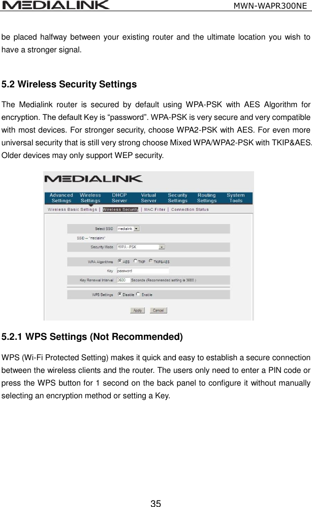
![MWN-WAPR300NE 37 WPA Algorithms: Provides TKIP [Temporal Key Integrity Protocol] or AES [Advanced Encryption Standard]. Key: Enter the pass phrase that consists of 8-63 ASCII characters excluding these five characters \ , ' ; " Key Renewal Interval: Set the key’s renewal period, which tells the device how often it should change the dynamic keys. It is not recommended to change this setting. 5.2.3 WPA2-PSK (WPA2-Personal) WPA2 (Wi-Fi Protected Access version 2) provides higher security than and WPA (Wi-Fi Protected Access). WPA Algorithms: Provides TKIP [Temporal Key Integrity Protocol] or AES](https://usermanual.wiki/Medialink/MWN-WAPR300NE/User-Guide-2208566-Page-42.png)
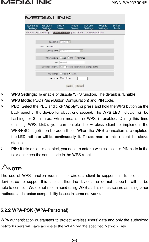
![MWN-WAPR300NE 38 [Advanced Encryption Standard]. Key: Enter the pass phrase that consists of 8-63 ASCII characters excluding these five characters \ , ' ; " Key Renewal Interval: Set the key’s renewal period, which tells the device how often it should change the dynamic keys. It is not recommended to change this setting. 5.2.4 WEP WEP (Wired Equivalent Privacy) provides 40-bit or 128-bit encryption to your wireless network. Default Key: Determines which Key will allow wireless clients to be accepted into the network. WEP Key1~4: These are keys that you can choose to make active. Only one key is used at a time. ASCII/HEX: Each Key can be entered as 5 OR 13 case sensitive ASCII characters excluding these five characters \ , ' ; " OR 10 OR 26 HEX characters including 0~9 and A~F only. 5.3 MAC Filter MAC Filter is based on the client’s wireless MAC address to permit or forbid specific clients access to the wireless network.](https://usermanual.wiki/Medialink/MWN-WAPR300NE/User-Guide-2208566-Page-43.png)