Medicalgorithmics PECGT-III Pocket ECG Monitor User Manual Part 1 092414
Medicalgorithmics S.A. Pocket ECG Monitor Users Manual Part 1 092414
Contents
- 1. Users Manual Part 1 092414
- 2. Users Manual Part 2 092414
Users Manual Part 1 092414

revised: September 09, 2014
USER MANUAL
PocketECG III
DUAL CHANNEL
Warsaw 2014
0197

Page 2 of 118
Copyright 2014 M
EDICALGORITHMICS
. No one is permitted to reproduce
or duplicate, in any form, this manual or any part thereof without
permission from M
EDICALGORITHMICS
.
M
EDICALGORITHMICS
assumes no responsibility for any injury or for any
illegal or improper use of the product that may result from failure to
use this product in accordance with the instructions, cautions,
warnings, or statement of intended use published in this manual.
Manufactured by:
M
EDICALGORITHMICS
SA
Al. Jerozolimskie 81,
02-001 Warsaw, Poland
tel./fax.: +48 22 825 12 49
e-mail: technical@medicalgorithmics.com
web: www.medicalgorithmics.com

Page 3 of 118
TABLE OF CONTENTS
1. PocketECG III description
1.1. PocketECG III components
1.2. PocketECG III architecture
1.2.1. Transmission and analysis delay
1.3. Data transmission technologies
1.3.1. Mobile telephony network
1.3.2. Encrypted internet channel
1.3.3. Micro SD card (optional)
1.3.4 Information to user
2. Symbols glossary
3. Warnings and cautions
3.1. Warnings
3.1.1. PocketECG transmitter
3.1.2. PC client application
3.2. Cautions
4. Intended use
5. Contraindications
6. Accessories
A. POCKETECG TRANSMITTER
7. Handling the device and its accessories
7.1. Starting the device
7.2. Main and backup batteries
7.2.1. Main battery charging
7.2.2. Backup battery charging
7.3. Stopping the device
7.4. SIM and flash memory cards
8. Test preparation
9. Supervisor and patient views
9.1. Supervisor view
9.1.1. Start/stop button
9.1.2. View tab
9.1.3. Settings tab

Page 4 of 118
9.2. Patient view
9.3. Method for calculating pause and heart rate
10. Alarms
11. Data structure and transmission to the remote server
12. Maintenance
12.1. Inspection of the device
12.2. Testing the device
12.3. Cleaning the device
12.4. Storing the device
12.5. Software updates
13. Safety rules for using the PocketECG transmitter
13.1. Electromagnetic compatibility (EMC)
B. PC CLIENT SOFTWARE
14. Equipment requirements
15. Installation
16. Distribution
17. Overview
17.1. Communication with remote server
18. Navigator
18.1. Introduction
18.2. Navigator toolbar
18.3. Adding and editing patient and specialist data
18.3.1. Patients
18.3.2. Specialists
18.3.3. Relations between specialists, patients and PocketECG
transmitters
18.4. Assigning patients / specialists to recording session
18.5. Downloading and removing recording session data
18.6. Remote communication with the transmitter
18.7. Communication with the SD card through USB
19.Event View
19.1. Introduction
19.2. Filtering and sorting of the events list
19.3. Events reviewing

Page 5 of 118
19.4. Navigation through the ECG recording
19.5. ECG display settings and transmitter settings
20. Full Disclosure
20.1. Introduction
20.2. Navigation through the ECG recording
20.3. ECG display settings and re-annotations
21. Trends
21.1. Acceleration trend
22. Impressions and Findings
23. Reports
23.1. Introduction
23.2. Reports viewing
23.3. Reports editing
24. Garbage
25. Archive
26. Tools Menu
C. ADDITIONAL INFORMATION
27. Medical incident
28. Troubleshooting
29. Technical parameters
30. Service
31. Declaration of conformity
32. Limited warranty statement
33. Software license agreement

Page 6 of 118
1. POCKETECG III DESCRIPTION
1.1. PocketECG III components
The
Medicalgorithmics Unified Arrhythmia Diagnostic System Pocket
ECG III
consists of:
• PocketECG transmitter, model: PocketECG III, type: PECGT-III
with the following accessories:
o Two rechargeable batteries, type: PECGB-III,
o The AC plug-in battery charger, type: PECGC-III,
• PC Client software
• User manual (hardcopy) for the patients
The
Medicalgorithmics Unified Arrhythmia Diagnostic System Pocket
ECG III is
compliant with:
• the essential requirements of the Council Directive 93/42/EEC,
• the requirements of the United States Food and Drugs
Administration.
• the requirements of the Health Canada Medical Devices
Regulations.
This user manual describes PocketECG transmitter, its accessories and
PocketECG PC client software.
1.2. PocketECG III architecture
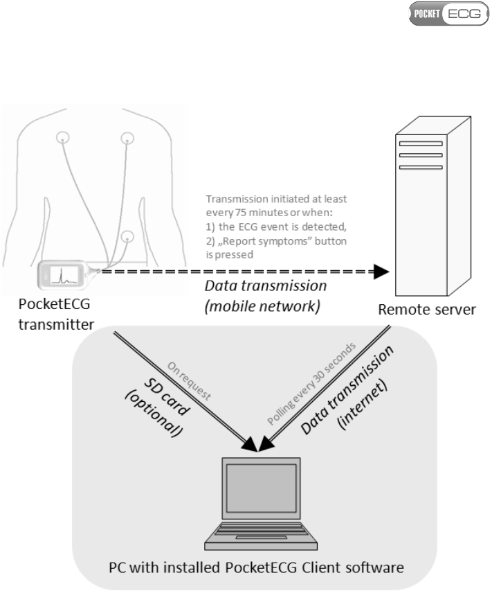
The functional block diagram of PocketECG III – Medicalgorithmics
Unified Arrhythmia Diagnostic System in combination with the data
transmission to the remote server is presented in Fig. 1.
Page 7 of 118
Fig.
1
Functional block diagram of PocketECG
III
Medicalgorithmics Unified
Arrhythmia Diagnostic System
The patient heart activity is digitized using a PocketECG transmitter.
The transmitter is equipped with digital accelerometer, generating
signals corresponding to the patient physical activity. An algorithm,
operating on the PocketECG transmitter automatically analyzes the
acquired ECG in real-time and transmits both: the ECG and acceleration
data to the remote server accessible by a Monitoring Center for
reviewing by trained medical staff. The ECG data comprises of ECG
annotations for all detected heart beats and the entire ECG signal. The
acceleration data comprises of results of patient activity estimation

Page 8 of 118
along with the waveforms of the acceleration signals. All detection
results along with the waveforms of the ECG and acceleration signals
may be reviewed using a PocketECG Client - PC based application.
Optionally, the ECG and acceleration data may be downloaded to the
Pocket ECG Client application from the SD card of PocketECG
transmitter using standard SD card reader connected to the PC through
USB interface.
1.2.1 Transmission and analysis delay
The ECG signal is interpreted by the software of PocketECG transmitter
with few seconds delay, which is relatively quick considering the
monitoring duration of a patient – i.e. which may last from one day to
several weeks. Therefore analysis with such short delay is considered
as performed in real-time. The transmission of data chunks is also
performed fairly frequently, with regard to the potential monitoring.
The use of this approach is to provide the arrhythmia analysis results
to the physician with short delay on an ongoing basis, which allows for
making a decision whether monitoring should be carried on (in order
to collect more data) or whether it should be terminated, assuming that
conclusive results were generated. This is beneficial for the patient,
who do not have to wear the device unnecessarily and also allows for
limiting the cost of monitoring – no need to transmit and analyze
unnecessary data.
In the worst case conditions, which are lack of mobile network signal,
the data will not be transmitted at all. However, acquired data is stored
on the micro SD card and can be optionally downloaded to the PC using
wired USB connection when the recording session is finished (micro SD
card reader is required). In case of limited access to the mobile
network, the data may be transmitted when the patient is in the
network range – limited times per day. Therefore the user has to be
aware of limitations related to monitoring and transmission using a
mobile network infrastructure.
The ECG signals are presented on the device screen about 1 second
after they are sampled by the PocketECG transmitter.

Page 9 of 118
The PocketECG transmitter initializes the data transmission to the
remote server:
1. at least every 75 minutes,
2. when the ECG event/abnormality is detected,
3. when "Report symptoms" button is pressed by the patient.
The PC Client software polls the remote server every 30 seconds. If
new data related to the selected recording session are available, the PC
Client downloads them automatically.
In order to download data stored on the micro SD card of the
PocketECG transmitter, the card must be removed from the transmitter
and inserted into the USB micro SD card reader. The PC Client user may
request to download the data from the micro SD card when successful
USB connection between micro SD card reader and PC is already
established.
1.3. Data transmission technologies
The description of the data transmission technologies utilized by the
PocketECG device is given in the following subsections.
1.3.1 Mobile telephony network
The Pocket ECG transmitter is equipped with communication module
providing access to mobile telephony network (quad band GSM EDGE,
UMTS 850 / 1900 / 2100MHz Diversity (850, 1900MHz)). The wireless
data transmission technologies used by the mobile telephony network
carriers like: GPRS, EDGE, HSDPA, HSUPA, are utilized to transmit the
ECG and acceleration data along with the results of automated signals
analysis to the remote server. The exact technology used for data
transmission depends on its availability.
The data transmission is triggered automatically based on results of
the automated ECG signal analysis, manually by the patient or

Page 10 of 118
periodically. The data transmission is initiated immediately after
detecting irregularities in the ECG signal or after pressing the "Report
symptoms" button on the transmitter by the patient (refer to Section
9.2 for detailed description). Otherwise, the data transmission is
triggered at least once every 75 minutes. Depending on the
transmission quality of service the time needed to upload patient
related data to the remote server may vary.
There is no minimal rate for data upload required for proper operation
of the PocketECG. However, a user must be aware that when the data
rate is extremely low the period of time required to transmit the data
may be very long. Therefore, it is recommended to ensure that the
mobile network allows data uploading with at least 10 kbps (average)
on the area where the patient is going to be monitored. It is easily
achievable in most of the existing mobile networks in the US/EU.
The PocketECG transmitter only transmits ECG and acceleration data
along with automatic analysis results related to a specific recording
session ID. The session ID is a unique identifier which consists of the
timestamp of the session start with 1 second accuracy and the unique
ID of the PocketECG transmitter. No personal data is entered on the
PocketECG transmitter nor transmitted through mobile telephony
network. The connection to the server comprises TCP/IP sockets and is
based on the transfer of the data files.
1.3.2. Encrypted internet channel
The internet encrypted channel is used by the PC client application for
reviewing the ECG and acceleration data that was sent to the remote
server by the patient monitors (PocketECG transmitter). Since the data
which is exchanged between the PC Client and the server includes
personal data, all of the communication channels need to be encrypted.
The PocketECG III uses a SSL-like authentication, authorization and
encryption mechanisms. The encrypted data is transmitted over
TCP/IP sockets in a binary form. The symmetric key exchange
algorithm uses the RSA cryptographic model while the block
encryption utilizes Triple Data Encryption Algorithm (TDEA). The
recommended minimal download and upload speed of the internet

Page 11 of 118
connection is 512 kbps and 64 kbps, respectively. The internet
connection of a lower speed may also be used. However, the user must
be aware that the access and reviewing of the ECG and acceleration
data stored on the remote server will be more time-consuming. Only
the server listens on TCP/IP sockets to accept incoming connection
requests. Neither the PocketECG transmitter nor the PC Client need to
open any ports, so the incoming connection rules don’t have to be
changed in the firewall software. If the PC Client is installed in an
environment which filters the outbound traffic, a rule which enables
connecting to the remote TCP port needs to be added to the firewall
software.
1.3.3. Micro SD card (optional)
The PocketECG transmitter is not equipped with USB connector. It does
not have any external connector and cannot be connected to any other
electronic equipment. The only data path for ECG and acceleration data
goes through mobile phone link between PocketECG transmitter and a
remote server. The ECG and acceleration data processed by the
PocketECG transmitter are:
1) stored on the flash memory card (microSD) of the PocketECG
transmitter,
2) transmitted using cellular networks technology to the remote
server.
In some circumstances like:
• no cellular phone service on the area where the patient is
monitored
• mobile network failure
• problems with internet connection on the PC with PC Client
application installed - data cannot be downloaded from a
remote server

Page 12 of 118
the data may be downloaded from the micro SD card to the PC using
card reader. The card reader either integrated with PC (most laptops
do have them) or connected to the PC through USB 2.0 interface may
be used. The data can be downloaded by the medical staff providing the
service to the patient when the recording session is already finished.
The USB transmission should be performed using wired connection
established between USB card reader and PC. The micro SD card must
be removed from the PocketECG transmitter and inserted into the
socket of USB card reader. The communication based on the file
transfer is safe as no personal data is stored on micro SD card.
1.3.4
FCC Requirements
FCC id: 2AB2MPECGT-III
This device complies with part 15 of the FCC Rules. Operation is subject
to the following two conditions: (1) This device may not cause harmful
interference, and (2) this device must accept any interference received,
including interference that may cause undesired operation.
Changes or modifications of any kind not expressly approved by
Medicalgorithmics SA could void the uses authority to use ECG.
Page 13 of 118
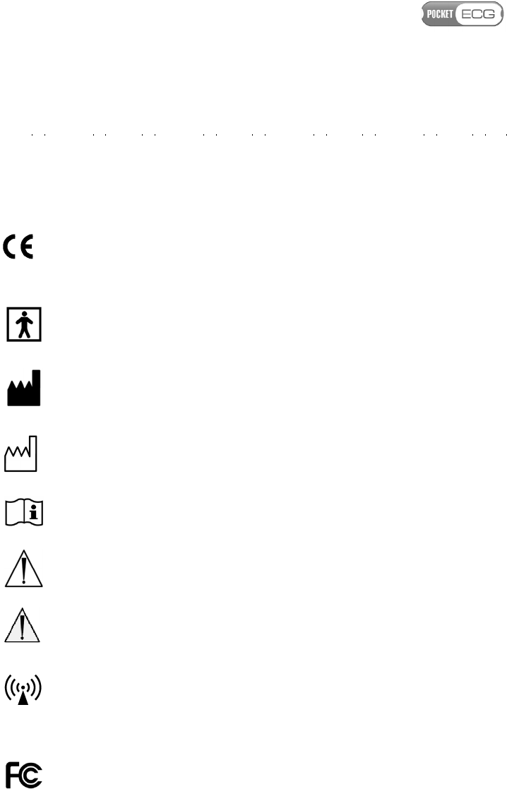
2. SYMBOLS GLOSSARY
The following symbols appear on the label placed on the PocketECG
transmitter's casing and in this user manual:
Symbol indicating compliance of the
PocketECG device with the main
requirements of Council Directive
93/42/EEC.
Symbol indicating that the PocketECG
transmitter is BF type equipment.
Manufacturer’s symbol – manufacturer’s
name and address is placed next to this
symbol.
Symbol indicating date of manufacture of the
PocketECG transmitter
Symbol indicating necessity to read user
manual of the PocketECG III.
Caution/Notices – read carefully
Warning – read carefully
Symbol indicating that the PocketECG
transmitter includes a radio wave
transmitters.
Symbol indicating that the PocketECG
transmitter fulfils the requirements of the
FCC (Federal Communication Commission)
Symbol indicating that it is a medical device
0197

Page 14 of 118
that needs to be protected from moisture.
IP20
Symbol indicating that the transmitter is
protected against solid particles up to 12,5
mm (fingers or similar objects) but it is not
protected against liquid ingress.
IP02
Symbol indicating minimum protection class
of protective case that can be used with
PocketECG III transmitter. It is marked on the
protection case intended to be used in
outdoor applications of PocketECG III
transmitter.
Symbol indicating that it is necessary to
dispose of the PocketECG transmitter in
compliance with appropriate regulations.
Symbol indicating that the PocketECG
transmitter poses hazards in all MR
(Magnetic Resonance) environments
PECGT-III
Transmitter type
Serial number of the PocketECG transmitter
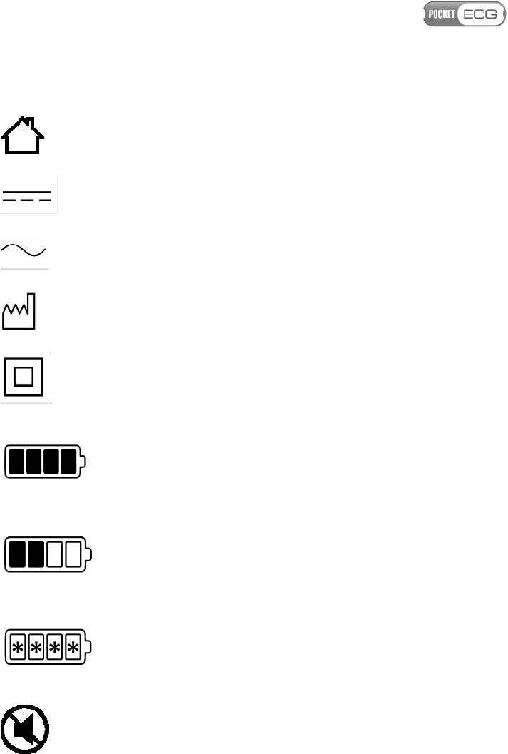
The following symbols appear on the label placed on the PocketECG
accessories (charger and/or battery) and in this user manual:
Symbol indicating recyclable materials
Page 15 of 118
Indoor use only
Symbol indicating direct current
Symbol indicating alternating current
Symbol indicating date of manufacture of the
charger/battery
Symbol indicating Class II equipment
Symbol reflecting behavior of the charger
light indicators - all light indicators are
turned on and emit green light (battery fully
charged)
Symbol reflecting behavior of the charger
light indicators - one or more light indicators
are turned on and emit orange light
(charging in progress)
Symbol reflecting behavior of the charger
light indicators - all light indicators blinks
and emit orange light (no battery in the
compartment)
Symbol indicating that particular action has
to be taken in order to stop the charger from
emitting sound
PECGC-III
Charger type

Page 16 of 118
PECGB-III
Battery type
Serial number of the charger/battery
Page 17 of 118
3. WARNINGS AND CAUTIONS
This section is to familiarize the user with applicable warnings and
cautions. Specific warnings and cautions can also be found in other
sections of the user manual.
3.1. Warnings
Warning statements alert to situations which, if not avoided, could
result in illness or injury of the patient.
3.1.1. PocketECG transmitter
WARNING.
T
HE
P
OCKET
ECG
TRANSMITTER DOES NOT
PROTECT AGAINST DEFIBRILLATION EFFECTS AND MAY BE
DAMAGED IF PLACED ON A PATIENT UNDERGOING
DEFIBRILLATION
.
R
EMOVE ELECTRODES
,
PATIENT LEAD
WIRES
,
AND THE
P
OCKET
ECG
TRANSMITTER FROM PATIENT
BEFORE DEFIBRILLATION
.
WARNING.
T
HE
P
OCKET
ECG
TRANSMITTER DOES NOT
DISTURB THE PACEMAKER OPERATION
.
H
OWEVER
,
FOR
PATIENTS WITH A PACEMAKER
,
MAINTAIN A MINIMUM
DISTANCE OF
6
INCHES BETWEEN THE TRANSMITTER AND
PACEMAKER
.
T
URN THE TRANSMITTER OFF IMMEDIATELY
AND PROVIDE APPROPRIATE PATIENT CARE IF YOU SUSPECT
THE TRANSMITTER AFFECTED THE PACEMAKER
.
WARNING.
T
HE
P
OCKET
ECG
TRANSMITTER IS NOT
INTENDED FOR INFANTS WEIGHING LESS THAN
10
KG
.
WARNING.
T
HE
P
OCKET
ECG
TRANSMITTER IS NOT
INTENDED FOR USE IN INTENSIVE CARE UNITS
.
I
T SHOULD
NOT BE USED WITH HIGH FREQUENCY SURGICAL DEVICES OR
DIRECTLY ON THE HEART
.

Page 18 of 118
WARNING.
D
ISCARD ELECTRODES AFTER EACH USE
.
WARNING.
D
O NOT USE IN THE PRESENCE OF A
FLAMMABLE ANESTHETIC MIXTURE WITH AIR OR OXYGEN OR
NITROUS OXIDE
.
WARNING.
T
O AVOID DANGER OF SWALLOWING KEEP THE
P
OCKET
ECG
TRANSMITTER PARTS AND ITS ACCESSORIES
AWAY FROM BABIES AND CHILDREN
.
WARNING.
D
O NOT USE ACCESSORIES OTHER THAN THOSE
RECOMMENDED BY THE MANUFACTURER
.
I
T MAY BE
DANGEROUS TO THE USER AND MAY AFFECT
ELECTROMAGNETIC COMPATIBILITY OF THE
P
OCKET
ECG
TRANSMITTER
.
WARNING.
T
HE
P
OCKET
ECG
TRANSMITTER CONTAINS A
L
ITHIUM
-
ION BATTERY
.
T
HERE IS A RISK OF FIRE AND BURNS
IF THE BATTERY PACK IS HANDLED IMPROPERLY
.
D
O NOT
ATTEMPT TO OPEN OR SERVICE NEITHER THE BATTERY PACK
NOR TRANSMITTER
.
D
O NOT DISASSEMBLE
,
CRUSH
,
PUNCTURE
,
AND SHORT EXTERNAL CONTACTS OR CIRCUITS
,
DISPOSE OF IN FIRE OR WATER
,
OR EXPOSE TO
TEMPERATURES HIGHER THAN
60°
C
(140ºF).
R
EPLACE
ONLY WITH BATTERIES SPECIFIED BY THE DEVICE
MANUFACTURER
.
R
ECYCLE OR DISPOSE OF USED BATTERIES
ACCORDING TO THE LOCAL REGULATIONS OR REFERENCE
GUIDE SUPPLIED WITH YOUR PRODUCT
.
WARNING.
D
O NOT USE THE
P
OCKET
ECG
TRANSMITTER
AT GAS STATIONS
,
FUEL DEPOTS
,
CHEMICAL PLANTS OR
WHERE BLASTING OPERATIONS ARE IN PROGRESS
,
OR IN
POTENTIALLY EXPLOSIVE ATMOSPHERES SUCH AS FUELLING
AREAS
,
FUEL STOREHOUSES
,
BELOW DECK ON BOATS
,
FUEL OR
CHEMICAL TRANSFER OR STORAGE FACILITIES
,
AND AREAS
WHERE THE AIR CONTAINS CHEMICALS OR PARTICLES
,
SUCH

Page 19 of 118
AS GRAIN
,
DUST
,
OR METAL POWDERS
.
T
HE USER SHOULD
OBSERVE RESTRICTIONS ON THE USE OF RADIO EQUIPMENT IN
SUCH PLACES
.
P
LEASE BE AWARE THAT SPARKS IN SUCH
AREAS COULD CAUSE AN EXPLOSION OR FIRE RESULTING IN
BODILY INJURY OR EVEN DEATH
.
WARNING.
N
EITHER THE
P
OCKET
ECG
TRANSMITTER NOR
ITS ACCESSORIES ARE WATERTIGHT
.
P
REVENT THE
P
OCKET
ECG
EQUIPMENT FROM GETTING WET
.
K
EEP THE
DEVICE IN DRY CONDITIONS WHEN SHOWERING
,
BATHING OR
WASHING
.
WARNING.
I
N ALL OUTDOOR APPLICATIONS
P
OCKET
ECG
TRANSMITTER MUST BE KEPT IN THE PROTECTIVE CASE WITH
PROTECTION CLASS AT LEAST
IP02.
T
HE
P
OCKET
ECG
TRANSMITTER CAN BE USED WITH THE PROTECTIVE CASE
AVAILABLE FROM THE MANUFACTURER OR ANY OTHER WITH
PROTECTION CLASS AT LEAST
IP02.
WARNING.
P
OCKET
ECG
III
HAS BEEN TESTED AND MEETS
FCC
RF
EXPOSURE GUIDELINES WHEN USED WITH AN
ACCESSORY THAT CONTAINS NO METAL AND THAT POSITIONS
THE HANDSET A MINIMUM OF
1.0
CM FROM THE BODY
.
U
SE
OF OTHER ACCESSORIES MAY NOT ENSURE COMPLIANCE WITH
FCC
RF
EXPOSURE GUIDELINES
.
D
O
NOT
USE THE DEVICE IN
A MANNER SUCH THAT IT IS IN DIRECT CONTACT WITH THE
BODY
3.1.2. PC client applications
WARNING.
T
HE
PC
CLIENT APPLICATIONS ARE NOT
INTENDED FOR USE IN INTENSIVE CARE UNITS
.
WARNING.
T
HE
PC
CLIENT SOFTWARE IS NOT INTENDED
FOR INFANTS WEIGHING LESS THAN
10
KG
.

Page 20 of 118
WARNING.
D
EVICE OPERATING
PC
CLIENT APPLICATIONS
SHOULD BE USED IN THE TEMPERATURE RANGE DEFINED BY
THE MANUFACTURER
.
WARNING.
D
O NOT USE DEVICE OPERATING
PC
CLIENT
APPLICATION IN GAS STATIONS
,
FUEL DEPOTS
,
CHEMICAL
PLANTS OR WHERE BLASTING OPERATIONS ARE IN PROGRESS
,
OR IN POTENTIALLY EXPLOSIVE ATMOSPHERES SUCH AS
FUELLING AREAS
,
FUEL STOREHOUSES
,
BELOW DECK ON
BOATS
,
FUEL OR CHEMICAL TRANSFER OR STORAGE
FACILITIES
,
AND AREAS WHERE THE AIR CONTAINS
CHEMICALS OR PARTICLES
,
SUCH AS GRAIN
,
DUST
,
OR METAL
POWDERS
.
T
HE USER SHOULD OBSERVE RESTRICTIONS
RELATED TO THE USE OF RADIO EQUIPMENT IN SUCH AREAS
.
B
E AWARE THAT SPARKS IN SUCH AREAS COULD CAUSE
EXPLOSION OR FIRE AND MAY RESULT IN BODY INJURY OR
EVEN DEATH
.
3.2. Cautions
Caution statements alert to situations which, if not avoided, may result
in equipment failure, equipment damage, or data loss.
Caution. Prior to starting a diagnostic session read
the PocketECG device manual carefully.
Caution. US Federal Law restricts this device to sale
by or on the order of a physician.
Caution. The ECG cables should not be bent, pulled
and wrapped around the device.
Caution. The batteries should be charged before the
first usage.

Page 21 of 118
Caution. Inspect the device and all accessories
before each use (see section 12).

Page 22 of 118
4. INTENDED USE
The PocketECG transmitter constitutes a part of the
Medicalgorithmics
Unified Arrhythmia Diagnostic System
PocketECG III and is intended to:
• acquire,
• analyze,
• visualize,
• record or/and transmit
the ECG and acceleration data. The PocketECG transmitter is attached
to patient’s body with three electrodes. The device is battery powered
from Lithium-ion battery with rated voltage of 3.7 V and is designed for
continuous use. The results of arrhythmia and ST elevation detection
are displayed, stored or/and transmitted along with ECG signals. The
acceleration signals are analyzed in order to determine the physical
activity of patient. It is assumed that the device can further transmit
the ECG and acceleration signals along with analysis results using
available wireless technologies.
The PocketECG III is intended for use under supervision of a physician
or those knowledgeable in all aspects of ECG morphology, rhythm and
arrhythmia. Having fulfilled the working conditions specified in the
manual, the device may be used when the patient is in the following
places: clinic, hospital, outpatient cardiology clinic, house, business
establishment, etc.
The PC client software is used for reporting and reviewing
ECG/arrhythmia diagnostic sessions. The reviewed ECG and
acceleration data is being transmitted from patients’ PocketECG
transmitter, through mobile telephony network to a remote server. The
PC client software connects with the remote server and downloads the
data which can then be viewed locally. The PC client software allows
for reviewing of the ECG and acceleration signals along with the

Page 23 of 118
annotations and creating the reports summarizing the recording
session results.
5. CONTRAINDICATIONS
The
Medicalgorithmics Unified Arrhythmia Diagnostic System
PocketECG III,
which consists of the PocketECG transmitter, and/or PC client software
is not intended to be used by patients who have been diagnosed with
life threatening arrhythmias and require hospitalization or patients
who require inpatient monitoring using a life-saving device.
The Pocket ECG III is not intended for use in surgical rooms, intensive
care units, intermediate or step-down units, emergency vehicles. The
PocketECG III is MR unsafe and should not be used in any magnetic
resonance environment.
6. ACCESSORIES
The following accessories are provided by the manufacturer in a
package with the PocketECG transmitter:
– A Lithium-ion battery pack providing rated voltage of 3.7 V,
type: PECGB-III, with capacity of 1700 mAh. Use only battery of
this type.
– AC plug-in charger type PECGC-III suitable for charging PECGB-
III type batteries.
WARNING.
U
NDER NO CIRCUMSTANCES THE DEVICE MAY BE
PLUGGED TO A DIFFERENT SOURCE OF POWER THAN INTENDED
BY THE MANUFACTURER
.
U
SING A DIFFERENT POWER SOURCE
IS HAZARDOUS AND MAY IMPAIR FUNCTIONING OF THE
EQUIPMENT OR RESULT IN SERIOUS INJURY TO THE USER
.
WARNING.
I
N ALL OUTDOOR APPLICATIONS
P
OCKET
ECG
TRANSMITTER MUST BE KEPT IN THE PROTECTIVE CASE WITH

Page 24 of 118
PROTECTION CLASS AT LEAST
IP02.
T
HE
P
OCKET
ECG
CAN BE
USED WITH THE PROTECTIVE CASE AVAILABLE FROM THE
MANUFACTURER OR ANY OTHER WITH PROTECTION CLASS AT
LEAST
IP02.
The following other accessories are needed for proper operation of the
device but are not enclosed in the PocketECG transmitter package:
– micro SD memory card
– SIM card
– ECG electrodes
Page 25 of 118
A
.
POCKETECG TRANSMITTER
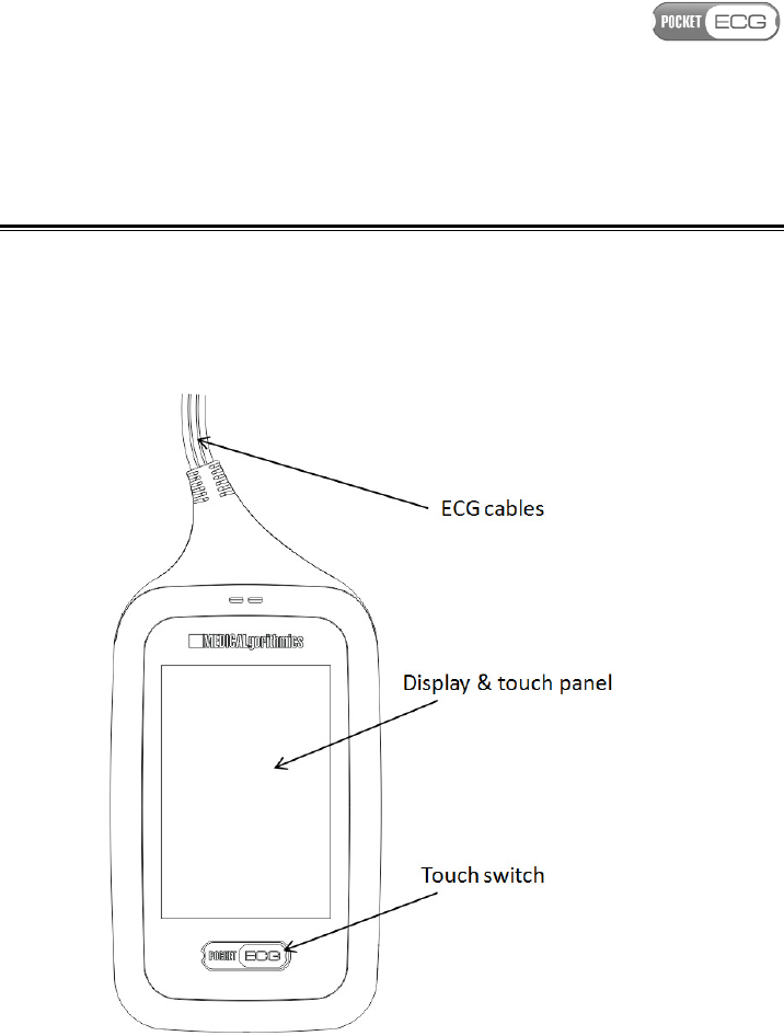
The PocketECG device (see Fig.2) transmits both the ECG and
acceleration signals along with the results of their analysis to a remote
server.
Fig. 2
PocketECG transmitter
The features of the PocketECG transmitter are as follows:
• processing of two ECG channels
Page 26 of 118
• 3-axis accelerometer - physical activity of patient is estimated
basing on analysis of acceleration signal
• 320x480 color display with touch panel
• micro SD / SDHC card socket
• SIM card socket
• backup power - main battery may be replaced without
interrupting recording session
7. HANDLING THE DEVICE AND ITS ACCESSORIES
CAUTION.
A
PATIENT SHOULD BE TRAINED BY A QUALIFIED
PERSONNEL BEFORE USING THE
P
OCKET
ECG
TRANSMITTER
.
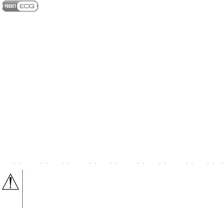
7.1. Starting the device
To start the PocketECG transmitter slide the battery into its
compartment, until it snaps shut (Fig. 3).
Page 27 of 118
Fig.
3
Battery inserting
After the battery is placed in the appropriate compartment of the
PocketECG transmitter, the device turns on automatically. The device is
ready for starting new recording session about 30 seconds after the
battery is placed in its compartment. A graphical user interface comes
on when the device is properly supplied with power and ready to work.
Caution. If no image is displayed within 30 seconds
after placing the battery in the compartment, the
battery is fully discharged or device does not
operate correctly due to the abnormal temperature
or humidity conditions.

Page 28 of 118
7.2. Main and backup batteries
A fully charged battery makes it possible to continuously monitor the
patient's ECG and acceleration signals using the PocketECG transmitter
for at least 24 hours.
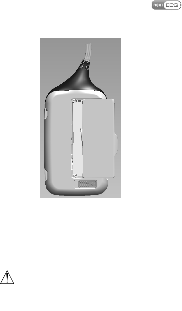
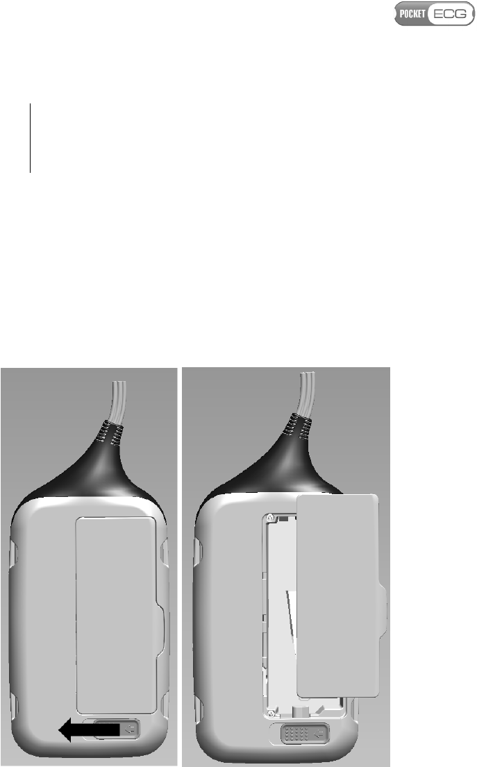
In order to replace the battery follow the instructions (see Figs. 4):
1. Slide the battery lock to release the battery;
2. Remove the battery;
3. Place fully charged battery until the lock clicks back into its
original position;
Caution. When replacing the battery, make sure the
contacts face the interior of the battery
compartment. If slipping the battery in requires
excessive force, check if you are putting it into the
case the right way.
The PocketECG transmitter is equipped with backup battery that is
intended to supply the device when the main battery is being replaced.
Removing main battery when the recording session has not been
initiated or has already been finished does not activate backup power
(the device turns off). When the main battery is being removed during
ongoing session, the transmitter operates continuously for up to 5
minutes powered from backup battery. After placing fully charged
main battery into its compartment, the transmitter starts to be
powered from main battery automatically.
Caution. The backup power is activated only when
recording session is ongoing.
Caution. If the level of main battery is low, replace
it with fully charged one, immediately. If the main
Page 29 of 118
battery remains removed from its compartment for
period longer than 5minutes, the transmitter is
switched off and the transmission is suspended.
7.2.1 Main battery charging
The discharged battery should be charged immediately if the
diagnostic session is intended to be performed for a period longer than
24 hours. On average the battery requires 4 hours to be fully charged.
Use charger provided along with PocketECG transmitter. If the device
is not going to be used for a longer time period, remove the battery.
Fig.
4
Replacing battery in the PocketECG transmitter
Page 30 of 118
When the battery gets damaged or worn out, follow standard disposal
procedure for Lithium-ion batteries.
Caution. The AC plug-in charger may require
suitable adapter and/or converter to convert to the
proper voltage when used outside the territory of a
country where it was provided by the
Medicalgorithmics distributor.
WARNING.
D
O NOT USE OTHER CHARGERS THAN THOSE
INTENDED FOR THE TYPE OF BATTERY USED IN THE
P
OCKET
ECG
TRANSMITTER IN ORDER TO PREVENT DANGER
OF BATTERY EXPLOSION
.
In order to charge the battery, follow the instructions:
1. Plug the charger into the AC mains;
2. Check whether a sound is generated indicating ready to use
state of the charger;
3. Put the battery into the charger cradle and verify whether
light indicator flashes orange indicating that the charging is
in progress;
4. Wait until the light indicator of the charger changes from
orange to indicating that the battery is fully charged.
7.2.2 Backup battery charging
The backup battery is installed inside the PocketECG transmitter and
cannot be removed. The charging of the backup battery is started
automatically and does not require interaction from the user. The
charging of backup battery is initiated when its state of charge falls
below predefined level and the main battery powering the device is
fully charged. Therefore, the discharged main battery should be always
replaced with a fully charged one.

Page 31 of 118
7.3. Stopping the device
In order to switch the transmitter off ensure that the recording session
is finished and remove the battery from its compartment.
7.4 SIM and flash memory cards
The PocketECG transmitter is equipped with a socket for a SIM and
micro SD memory cards (see Fig. 5). The ECG and acceleration data are
stored on SD card during recording session and further transmitted
through mobile telephony network to a remote server.
The SIM card is required in order to allow data transmission through a
mobile telephony network. This card is provided by the mobile
network operator. If your transmitter is not already equipped with SIM
card please contact your PocketECG service provider for assistance.
In case of limited access to mobile telephony network data are stored
on SD card until they can be successfully transmitted. It is
recommended to use reliable SD cards of minimum 1 GB capacity
produced by the Verbatim, SanDisk and other experienced
manufacturers. The PocketECG transmitter operates with the micro SD
and micro SDHC (high capacity) cards.
Caution. The SIM and micro SD cards must be
placed in its compartment before new recording
session is started.
8. TEST PREPARATION
Only high quality electrodes with fast conducting gel should be used
with the PocketECG transmitter. We recommend using electrodes
designed for Holter monitoring. Single-use electrodes last for a limited
time period and should not be used for longer than specified by their
manufacturer. Fresh electrodes contain wet gel; if the gel is spongy the

Page 32 of 118
electrodes are of poor quality or past their use-by date. Usually,
electrodes last no longer than 2-3 weeks after opening the box.
Caution. Verify the use-by dates on applied
electrodes to make sure they have not expired.
Caution. ECG electrodes can cause skin irritation.
Examine the skin for signs of irritation or
inflammation and avoid placing of the electrode in
those areas.
WARNING.
T
HE SNAPS OF THE ECG LEAD WIRES ARE MADE
OF METAL CONDUCTING THE CURRENT AND ARE INTENDED TO
BE CONNECTED WITH ELECTRODES PLACED ON A PATIENT
'
S
BODY
.
T
HE SNAPS OF THE LEAD WIRE SHOULD BE CONNECTED
NEITHER TO ANY OF THE
P
OCKET
ECG
ACCESSORIES NOR
OTHER EQUIPMENT
.
N
EVER CONNECT THE LEAD WIRE SNAPS
WITH ANY SOURCE OF ELECTRIC POWER SUCH AS POWER
OUTLETS
,
POWER SUPPLIERS
AND
BATTERIES
.
A special preparation should be applied to patient’s skin before placing
the electrodes. Do not use high-proof alcohol as it may dry up the
epidermis and distort the ECG signal transmitted by the PocketECG
device. In order to prepare patient’s skin follow these instruction:
1. Explain the procedure to the patient;
2. Remove hair from the place where the electrode is to be attached;
3. Degrease and prepare the skin;
4. Place the electrodes on patient’s body and connect the ECG cables of
the PocketECG transmitter as shown in Figs. 5.
Caution. Always make sure that the electrodes are
placed correctly.
Page 33 of 118
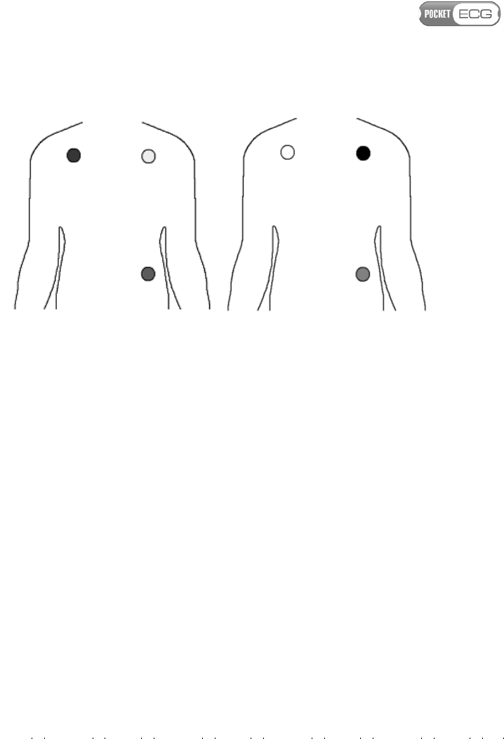
Fig. 5 Connecting ECG cables of the PocketECG transmitter to
electrodes on patient’s body (cable clips colors complying with the
EU requirements - left, US requirements - right)
5. Secure each lead wire. Cables of the PocketECG device should be
attached to the electrodes in a way that reduces movements causing
signal artifact.
When the amplitude of the ECG recording is very low (below 0.5 mV),
we recommend gently wiping the epidermis with a very fine,
disinfected, special sandpaper or putting the electrodes in a new place.
Transmitting signal at a level lower than indicated could negatively
impact its analysis.
When electrodes are connected to the PocketECG transmitter as shown
in Fig. 5 it is possible to monitor limb lead II and III. Green (red in case
of US) cable snap is attached to a referential electrode of both ECG
leads. Physician may order monitoring other profiles.
9. SUPERVISOR AND PATIENT VIEWS
There are two main views of the graphic user interface: supervisor and
patient. The 'supervisor view' is intended to be used by the medical
staff and provides access to all options of the software. The 'patient
view' is presented to the patient during entire recording session and
gives only limited access to software functions.
GREEN
RED
YELLOW
RED
WHITE
BLACK
Page 34 of 118
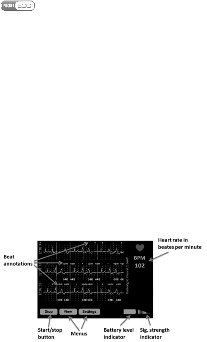
9.1. Supervisor view
The graphical user interface presented to the user in the 'supervisor
view' mode is shown in Fig. 6. The waveforms of recorded ECG signals
together with annotations generated by the analysis algorithm are
plotted in three rows. Each row corresponds to six seconds of
recording. Basing on displayed signals and annotations trained user
may verify the proper electrode placement and proper initialization of
the recording session. Furthermore, the heart rate in beats per minute
is presented in the upper right corner of the screen.
There are three tabs located in the bottom of the screen providing
access to the software options:
• Stop/Start – used for starting and finishing of the recording
session,
• View – channel selection, signal scaling, etc.
• Settings – session settings
The icons indicating the battery level and signal strength of the mobile
network are displayed in right bottom corner of the screen. Detailed
description of these both indicators is given in the section 9.2.

Page 35 of 118
Fig. 6 'Supervisor view' of
the graphical user interface
9.1.1. Start/stop button
The Start/Stop button enables starting and finishing recording
sessions. When session is not yet initiated the button is displayed as a
"Start" button. Otherwise, the button is marked with "Stop" command -
when pressed cause the recording session to finish.
When the recording session begins the ECG signal is displayed on the
screen along with annotations of the classified beats and arrhythmias.
The patient’s heart rate is displayed in the top right corner of the
screen of the PocketECG transmitter. After starting a new recording
session, verification of electrodes placement should be performed. In
order to verify the electrodes placement, follow the instructions:
1. Make sure that colors of the ECG clips correspond to those
presented in Fig. 5a (EU) or 5b (US).
2. Verify the ECG signal quality for both available channels by
observing the ECG signal waveform on the screen.
Caution. If the ECG signals are not presented on the
PDA display and/or the "EL" annotation is
displayed, the ECG signal is not analyzed due to the
overload of the PocketECG transmitter or incorrect
connection between lead wires and patient's
electrodes. The similar effect may occur when ECG
electrodes are used and should and signal quality is
insufficient.
9.1.2. View tab
The View tab contains the following options:
Page 36 of 118
• Patient view - switches the user interface into the 'patient view'
• Resize ECG - switches the length of the ECG waveforms displayed
on the screen
•
Zoom in amplitude – doubles the ECG amplitude zoom,
•
Zoom out amplitude – reduces the ECG amplitude zoom by half.
•
Reset zoom – restores the default amplitude zoom of the ECG
signal,
• Switch ECG channel – switches between the first and the second
ECG channel to be displayed on the device screen,
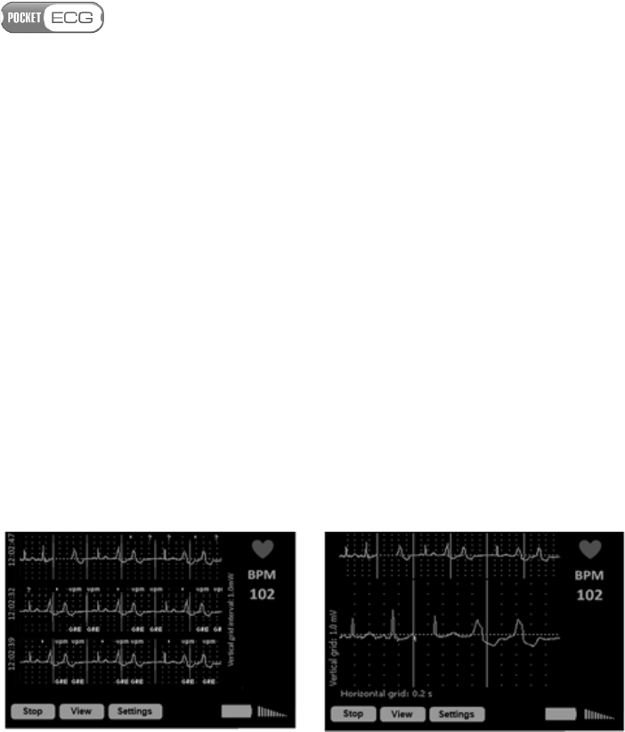
The user may select whether small or large ECG waveforms should be
displayed (see Fig. 7).
Fig.
7
Small (left) and large (right) ECG waveforms
Small waveforms correspond to 18 seconds of ECG signal (each row
corresponds to 6 seconds). When 'large ECG waveform' mode is
selected, 6 seconds of signal is presented in the top of the screen.
Additionally, zoomed waveform corresponding to 3 seconds of ECG is
presented below.
9.1.3. Settings tab
Analysis settings can be accessed any time during software operation.
The Settings tab contains following options:

Page 37 of 118
• Arrhythmia Settings – parameters for arrhythmia classification:
o
Pause: N ms – pause above N milliseconds ,
o Asystole: above N ms – asystole above N milliseconds,
o Bradycardia: below N BPM – bradycardia below N beats
per minute,
o V tachycardia: above N BPM – ventricular tachycardia
above N beats per minute,
o SV tachycardia: above N BPM – supraventricular
tachycardia above N beats per minute,
o
Premature: above N % - premature ectopic beats above N
%
o Multiform: sensitivity N – N level of sensitivity for
detection of multiform ventricular events,
o Pacer: On/Off – pacemaker switched on/off.
• Session Settings - configuration of the PocketECG transmitter:
o Power saving – when set the device is automatically
switched to power saving mode after a short period of
inactivity on the patient view (display is off, etc.),
o Send ECG events through Internet – ECG events are
transmitted when this option is selected (default),
o Stream ECG and annotations – ECG data are streamed to
the remote server when this option is selected (default is
off),
o ECG strip at least every N minutes – ECG transmission is
triggered at least once every N minutes,
o Comm. srv– remote server address and port number, where
processing results and signals are sent,
o Ftp srv– remote server address,

Page 38 of 118
o Path: /XXX – remote server folder name,
o User name: - name of the user logging in to remote server
o Password: ******* - hidden password – area showing
whether password was entered,
o Restore Defaults – button for restoring standard remote
server settings.
• About - contains following options:
o Software version - displays version of software operating
PocketECG transmitter,
o Session info - displays window with following information
related to the recording session:
- COM: [ xxx ][ nnnnnnn ][ nnnnnnnnn ] – communication
status (first brackets from the left), the number of files
transmitted to the server (second brackets from the left),
the number of files queued for transmission (third
brackets from the left)
- TIME: DDd HHh MMm SSs – time elapsed since the
beginning of the session (DAYS HOURS MINUTES
SECONDS),
- MEM: XXXXX MB free: space available on the micro SD
memory card
• ID: YYYYMMDDHHMMSS_XXXXXXXXXXXXXXXXX(…):
Unique session ID.
Page 39 of 118
Caution.
The first bracket of the communication
text
field informs about the status of the wireless
connection between the PocketECG transmitter and
the remote server. The '[OK]' text string indicates
that the connection has been established
successfully. Otherwise, an error code will be
displayed.
The settings related to the connection with the remote server (Comm.
srv, Ftp srv, Path, User name, Password) are read-only. These
parameters are configured automatically during the installation and
are stored in the 'settings.xml' file. The user should not modify the
settings.xml file unless instructed by the PocketECG service technical
support.
Caution.
The
PocketECG transmitter
c
onfigures the
connection with the remote server automatically. If any
problems with the configuration occur, please contact
your PocketECG distributor or service provider.
Page 40 of 118
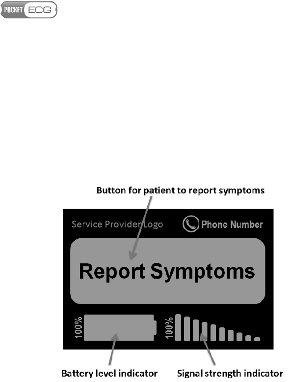
9.2. Patient view
The graphical user interface should remain in the 'patient view' (see
Fig. 9) when recording session was successfully initiated and electrode
placement was verified by the medical staff. The patient has no access
to the settings of the application and other information, when the
graphical user interface is switched to the 'patient view'.
Fig.
9
'Patient view' of the graphical user interface
The logo of service provider as well as phone number to help desk is
displayed on the top of the screen. In the middle of the screen a large
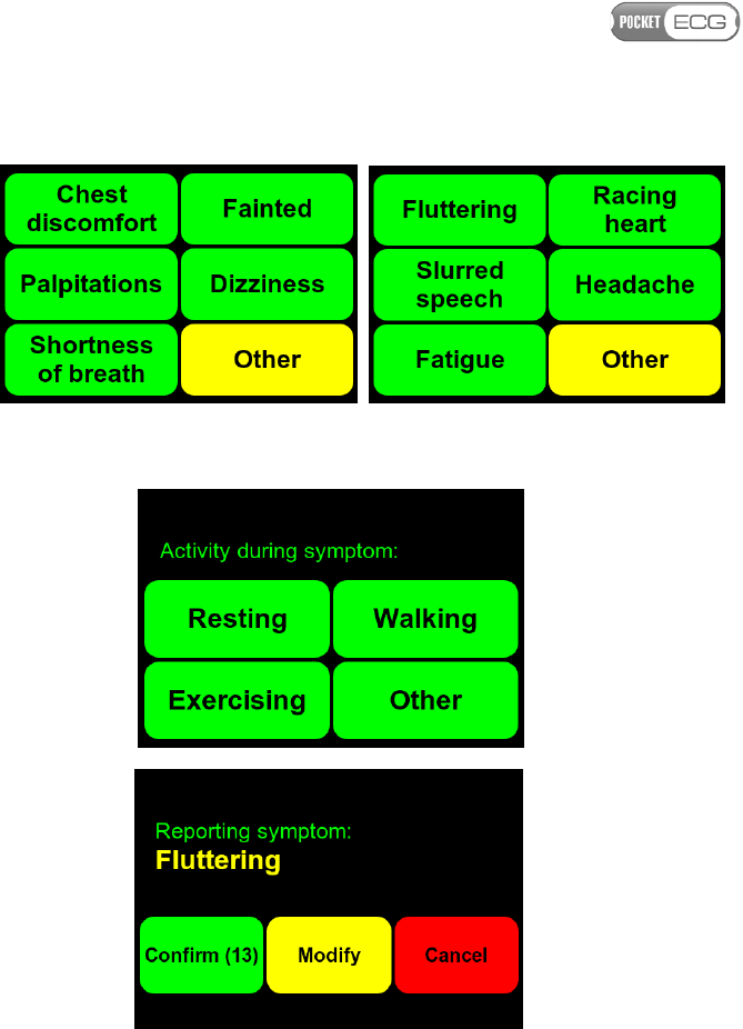
'Report Symptoms' button is displayed. The patient can press the
'Report Symptoms' button and then select the particular symptoms
from the list (see Fig. 10). Patient have to indicate when symptoms
occurred and afterwards symptom must be confirmed (Fig. 11). If the
selected symptom is wrong the patient may modify it after pressing
'Modify' button. Otherwise, the selected symptom is confirmed
automatically after 5 seconds.
Page 41 of 118
Fig. 10 Symptoms list
Fig. 1
1
A
ctivit
y
during symptom and
symptoms confirmation screen
There are two indicators displayed in the bottom of the screen:
• battery level indicator
• indicator of strength of mobile network signal
Page 42 of 118
Both indicators are accompanied with the textual information
expressing the battery charge state and signal strength in percentage
scale. Additionally, the color of the battery indicator represents its
state of charge in the following way:
Icon color
Battery
level/
status
Green
between 100 and 40%
Y
ellow
between 40 and 20%
Red
below 20%
Black & blinking
d
ev
ice powered from
backup battery
Both indicators are also displayed in the 'supervisor view' in the right
bottom corner of the screen (see Figs. 6 to 8).
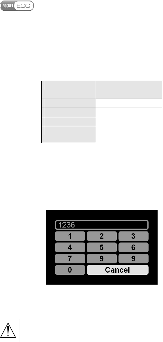
In order to switch to the 'supervisor mode' the service provider logo
must be kept pressed for at least 3 seconds and then the unique code
must be typed (see Fig. 12).
Fig.
1
2
Terminal for entering the unlocking code
Caution. The unlocking code is: 1 2 3 6.

Page 43 of 118
9.3. Method for calculating pause and heart rate
Pause is calculated using (as an input) QRS detection results. If a
distance between consecutive QRS complexes exceeds predefined
(pause) threshold, then the beat label annotation is marked as pause.
Heart rate is calculated using (as an input) QRS detection results. HR is
calculated for minute intervals: If within the analyzed minute, there is a
sufficient number of QRS complexes, then minutely HR value is a
median value of R-R intervals within that minute.
Practically at least 10 R-R pairs are required to calculate the heart rate.

Page 44 of 118
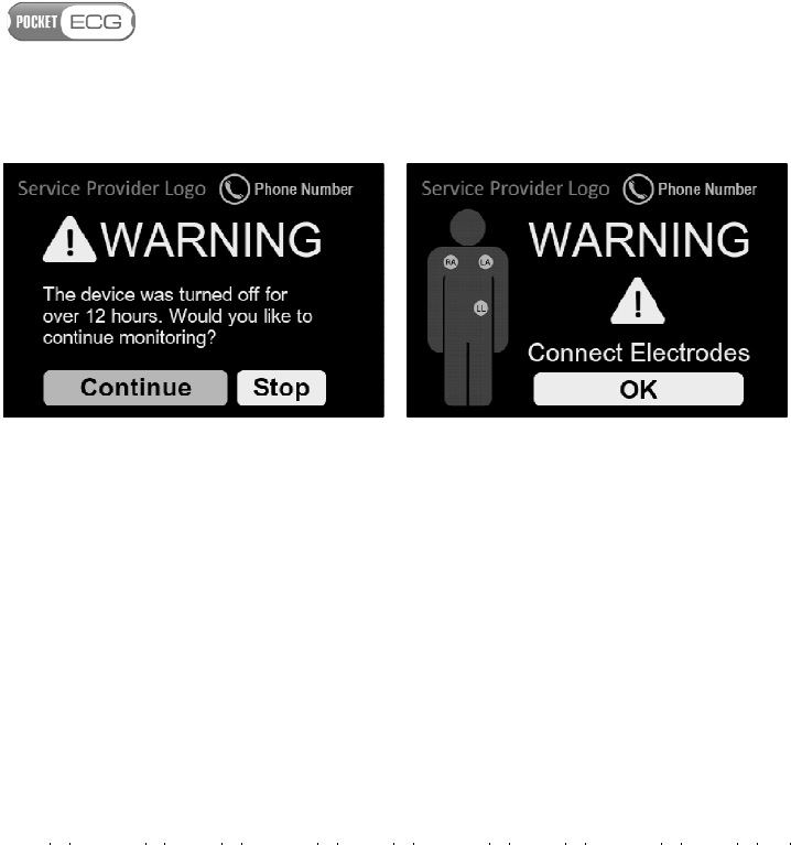
10. ALARMS
The PocketECG transmitter generates following alarms requiring user
attention (see Fig. 13):
Alarm Description Action
No memory card
The micro SD card is not
installed in its
compartment and the
session cannot be
initialized.
Install micro SD card or
replace damaged one
No
network
The PocketECG
transmitter cannot
connect to the mobile
phone network - data
cannot be transmitted.
Keep the PocketECG
transmitter in the area
where mobile network
is accessible.
Replace battery
The battery is
discharged. The data are
not transmitted to the
remote server.
Replace the battery
with the fully charged.
Insert battery
The PocketECG
transmitter cannot find
the battery
Insert the battery to the
PocketECG transmitter
ECG module
error
The ECG module
malfunction.
Turn off and then
turn
on the device. If the
module still does not
operate correctly, call
service provider.
The device was
turned off for
over 12 hours.
Would you like
to continue
The PocketECG
transmitter was turned
off for over 12 hours.
Make sure, that you
have to stop or continue
secession, call service
provider.

Page 45 of 118
monitoring?
Connect
Electrodes
Electrodes contact loss.
The ECG signal data are
not transmitted to the
remote server.
Put on the electrodes to
your body.
Page 46 of 118
Fig. 1
3
Warnings displayed
by the PocketECG transmitter
11. DATA STRUCTURE AND TRANSMISSION TO THE REMOTE
SERVER
The PocketECG transmitter analyzes the ECG signal on a beat-by-beat
basis. Each beat is annotated and described by the so-called beat
annotation structure. The structure contains:
• beat type annotation,
• arrhythmia type annotation,
• ST level elevation / depression in micro volts, for each ECG
channel,
• PQRST shape coefficients,
• Noise level (in micro volts),
• ADC interference level (in micro volts),

Page 47 of 118
Depending on the circumstances and signal characteristics, registered
data can be sent to a remote server specified in the settings if the ‘Send
ECG events through Internet’ option has been selected. Signal is
transmitted automatically based on the data analysis, or periodically or
the transmission is triggered by the patient (by pressing the ‘Report
symptoms’ button. The data is transmitted via the mobile telephony
network.

Page 48 of 118
12. MAINTENANCE
The PocketECG transmitter type: PECGT-III and battery charger type:
PECGC-III, manufactured by Medicalgorithmics S.A. are designed for 5
years continuous use if properly operated. After the devices have been
used for 5 years it should be recycled according to the local recycling
program or refurbished by the manufacturer. If you have any questions
or problems please contact Medicalgorithmics S.A. service using
contact details from section “30. Service”.
The capacity of the PocketECG Li-Ion battery decreases with normal
use over time. The battery must be replaced with a new one after 300
charging cycles or after 2 years of using.
The maximal life time of a particular version of PC Client software is
determined either by support period provided by Microsoft for the
latest version of MS Windows operating system, that is compatible
with technical specification of a particular version of PC Client
software, or by support period provided by Microsoft for the
Microsoft.NET Framework version used to build a particular version of
PC Client software, whichever expires first.
12.1 Inspection of the device
Prior to starting a recording session, the user should check the device
in accordance with the following instructions:
1. Inspect the patient cable bends, cuts and cracks on the case;
2. After placing the fully charged battery into its compartment
check whether proper graphical interface is displayed;
12.2 Testing the device
At least one a year the user responsible for efficient operation of the
device, should check its functional efficiency and verify the correctness

Page 49 of 118
of displayed messages and check the condition of the equipment,
especially the cables by performing the following operations:
1. Connect ECG simulator (e.g. Netech MiniSim 1000 or similar) to
the patient cable of the PocketECG transmitter and adjust
typical parameters (heart rate, amplitude) of generated ECG
signal;
2. Start a new recording session;
3. Check for normal appearance of the waveforms with
appropriate amplitude and without excessive noise. Check if
signal annotations are properly displayed. If ECG simulator
allows for arrhythmia simulating you may decide to check
whether they are properly detected (it will prove appropriate
operation of the device);
4. Try to bend the patient cable simulating typical bending caused
by patient’s movements and verify whether this causes
distortions of the ECG signal.
5. Remove the main battery and check whether device operates
without interruptions (device is switched to a backup power
automatically).
If the PocketECG transmitter falls or gets hit, a functional efficiency
check should be performed by the patient (simply try to start new
diagnostic session) or person responsible for efficient operation of the
device according to the above instructions. If you suspect that
something is wrong with the device contact the manufacturer’s service.
Caution. Do not remove the casing of the PocketECG
transmitter and do not attempt to repair the device
if it does not function properly. This may damage the
device.
12.3. Cleaning the device

Page 50 of 118
The outer surface of the device and lead wires can be wiped with a wet
soft cloth and soft soap dissolved in water or an alcohol-based
disinfecting agent. The device should be cleaned appropriately for
intended use and following procedures binding for the institution
where the equipment is used.
Caution. Do not let soap or water get inside the
PocketECG transmitter. It is not waterproof.
When cleaning or using the equipment, never get the cables and the
connectors wet.
Should the PocketECG transmitter get accidentally wet, dry it
immediately (leave the device with removed battery cover in the warm
and wet room for at least 24 hours). After drying turn the device on to
check if it functions properly. Should you have doubts whether the
device functions properly, contact the manufacturer’s service.
12.4. Storing the device
Remove the rechargeable battery from the device before storing it. This
prevents the battery from accidental discharge and reduces the risk of
its damage. Observe the environmental storage conditions. See section
29 Technical parameters of PocketECG transmitter.
12.5. Software updates
The software operating PocketECG transmitter should not be modified
or updated by anyone except the manufacturer or technical staff
responsible for its servicing. There are two methods for updating the
software of the PocketECG transmitter:
• The installer of new software version must be stored on the
microSD card. After powering the device the installer is
automatically launched. It removes previous version of the
software and installs the new one.

Page 51 of 118
• The PocketECG transmitter must be connected to the computer
using USB port available after casing removal. When the
connection is successfully established, the software installer
must be executed on the PC. The installer updates the software
version in the PocketECG internal memory.

Page 52 of 118
13. SAFETY RULES FOR USING THE POCKETECG TRANSMITTER
1. One device is intended to monitor only one patient at a time.
2. It is recommended for the device to work in room temperature.
3. Air in rooms where the device works should be free of caustic gasses,
steam and dust. Although the device is powered from 3.7V and does
not allow for power intake larger than 3A it is not guaranteed that it
cannot produce spark which could initiate explosion.
4. The patient should check with the appropriate airline carrier to
confirm that PocketECG transmitter which is similar to the regular
mobile phone may be used on the airplane during take-off, flight and
landing.
5. Due caution should be exercised when handling the device. It is
necessary to avoid excessive stretching and sudden jerking of cables
connecting the PocketECG transmitter with electrodes placed on
patient’s body.
6. Parts that wear out and are intended for single use should be used in
accordance with binding regulations and cannot be re-used. This
especially concerns the electrodes placed on patient’s body, which
should be replaced with new ones after no longer than 24 hours if the
diagnostic session is to be continued. Users (physicians, patients, etc)
are trained in this respect and are advised to get familiar with this
instruction.
7. The ECG cable is permanently attached to the PocketECG
transmitter. In case of damage, do not repair or replace it, because it
may negatively influence the electromagnetic compatibility of the
device. Damaged ECG cable can be replaced only by the manufacturer’s
service.
8. Manufacturer is not liable for damage to the PocketECG transmitter
caused by improper operation of the device or neglecting guidelines
included in the user manual.
Page 53 of 118
9. Manufacturer accepts liability for safe operation of the PocketECG
transmitter, only when the device is used as intended and in
accordance with the user manual.
10. The PocketECG QRS detection algorithm adapts to noise and
disturbances level obscuring the signal, i.e. in case of higher noise level,
the QRS detection procedure becomes less sensitive. The minimum
QRS detection level is set to 0.16 mV.
WARNING.
T
HE RESULTS OF AUTOMATED
ECG
SIGNAL
ANALYSIS MAY BE INACCURATE IF AMPLITUDE OF THE
QRS
COMPLEXES IS LOWER THAN
0.16
mV.
11. The capacity of the PocketECG Li-Ion battery decreases with
normal use over time. The battery must be replaced with a new one
after 300 charging cycles or after 2 years of using.
12.
The conductive parts of ECG cables are intended to be connected
only to the ECG electrodes. They should not be connected to any
conductive parts of any objects including earth.
13.1 Electromagnetic compatibility (EMC)
The PocketECG transmitter needs special precautions regarding EMC
and needs to be installed and put into service according to the EMC
information provided in the user manual.
WARNING.
T
HE
P
OCKET
ECG
TRANSMITTER IS
MR
U
NSAFE
,
AND SHOULD NOT BE USED IN ANY MAGNETIC RESONANCE
ENVIRONMENT
.
WARNING.
U
SE OF ACCESSORIES OTHER THAN THOSE
SPECIFIED IN SECTION
6,
WITH THE EXCEPTION OF THE
ACCESSORIES SOLD BY THE MANUFACTURER OF THE
P
OCKET
ECG
TRANSMITTER AS REPLACEMENT PARTS FOR INTERNAL

Page 54 of 118
COMPONENTS
,
MAY RESULT IN INCREASED EMISSION OR
DECREASED IMMUNITY OF THE
P
OCKET
ECG
TRANSMITTER
.
Caution. Sources of electromagnetic radiation like:
• portable and mobile radio frequency (RF)
communications equipment (e.g. cellular phones,
mobile radio),
• radio frequency identification systems (RFID)
• devices using one or more of the following wireless
technologies: WiFi (IEEE 802.11), Bluetooth (IEEE
802.15), ZigBee (IEEE 802.15.4), WiMax(IEEE
802.16), Ant, etc,
• base stations for radio (cellular/cordless)
telephones and land mobile radios, amateur radio,
AM and FM radio broadcast and TV broadcast,
• metal detectors
can affect the PocketECG transmitter.
Caution. Sources of strong electromagnetic radiation
such as radio transmitters, wireless personal
transmitters working in the 80-2500 MHz frequency
band may disturb the ECG signal and disturb the
automated ECG signal analysis.
It is recommended to keep the PocketECG transmitter as far as possible
from all equipment combining RF transmitters. Try to reorient or/and
relocate PocketECG transmitter when the ECG signal displayed on the
screen of is partially masked by disturbing signal despite the ECG
electrodes are properly placed on the patient skin.
In case of further problems with the equipment operation, the medical
service provider should be contacted for support.

Page 55 of 118
PocketECG III device and any of its components should not be used for
patient monitoring during any diagnostic tests or medical treatment
performed using:
• computed tomography (CT) systems,
• positron emission technology (PET),
• diathermy systems
If the patient is going to be examined/treated using any of the above
diagnostic systems while being monitored with the PocketECG III
device, it is recommended to follow the instructions:
1. Contact your medical service provider or medical professional
supervising your recording session to inform that you are going
to remove the PocketECG transmitter for some time due to the
medical examination/treatment.
2. Disconnect the ECG lead wires of the PocketECG transmitter
from the electrodes placed on your body.
3. Leave the PocketECG transmitter in a place where it will not be
exposed to any disturbing radiation generated by the medical
system that is going to be used. Do not stop the recording
session.
4. When the examination/treatment is finished, replace the
electrodes if necessary and connect the lead wires of the
PocketECG transmitter to the electrodes.

Page 56 of 118
Guidance and manufacturer's declaration- electromagnetic emission
The PocketECG transmitter is intended for use in the electromagnetic environment specified
below. The customer or the user of the PocketECG transmitter should assure that it is used in
such emission environment.
Emissions test Compliance Electromagnetic environment - guidance
RF emissions
CISPR 11 Group 1
The PocketECG transmitter uses RF energy only for
its internal function and transmission of the data
through mobile phone network. The transmitter
does not radiate any RF energy for diagnostic
purposes.
RF emissions
CISPR 11 Class B
The PocketECG transmitter is suitable for use in all
establishments, including domestic establishments.
The device has no connection to the public low-
voltage power supply network.
Harmonic emissions
IEC 61000-3-2
Not
applicable
Voltage fluctuations/
flicker emissions IEC
61000-3-3
Not
applicable
Guidance and manufacturer's declaration- electromagnetic immunity
The PocketECG transmitter is intended for use in the electromagnetic environment specified
below. The customer or the user of the PocketECG transmitter should assure that it is used in
such emission environment.
Immunity test IEC 60601 test level Compliance level Electromagnetic
environment - guidance
Electrostatic
discharge (ESD)
IEC 61000-4-2
± 6 kV contact
± 8 kV air
± 6 kV contact
± 8 kV air
Floors should be wood,
concrete, or ceramic tile. If
floors are covered with
synthetic material, the
relative humidity should
be at least 30%.
Electrical fast
transient/burst
IEC 61000-4-4
±2 kV for power
supply lines
±1 kV for input/output
lines
Not applicable
Surge
IEC 61000-4-5
±1 kV line(s) to line(s)
±2 kV line(s) to earth Not applicable
Voltage dips,
short
interruptions, and
voltage variations
on power supply
input lines.
<5 % U
T
(>95 % dip in
U
T
) for 0.5 cycle
40 % U
T
(60 % dip in
U
T
) for 5 cycles
70 % U
T
(30 % dip in
Not applicable

Page 57 of 118
IEC 61000-4-11 U
T
) for 25 cycles
<5 % U
T
(>95 % dip in
U
T
) for 5 s
Power
frequency
(50/60Hz)
magnetic field
IEC 61000-4-8
3 A/m 3 A/m
Power frequency
magnetic fields should
be at levels
characteristic of a
typical location in a
typical commercial or
hospital environment.
NOTE: U
T
is the a.c. mains voltage prior to application of the test level.
Guidance and manufacturer's declaration- electromagnetic immunity
The PocketECG transmitter is intended for use in the electromagnetic environment specified
below. The customer or the user of the PocketECG transmitter should assure that it is used in
such emission environment.
Immunity test
IEC
60601
test level
Compliance
level Electromagnetic environment - guidance
Conducted RF
IEC 61000-4-6
3 Vrms
150 kHz
to 80
MHz
3 Vrms
Portable and mobile RF communications
equipment should be used no closer to any
part of the PocketECG transmitter, including
cables, than the recommended separation
distance calculated from the equation
applicable to the frequency of the
transmitter.
Recommended separation distance
( )
Pd 17.1=
Radiated RF
IEC 61000-4-3
3 V/m
80 MHz
to 2.5
GHz
3 V/m
( )
Pd 17.1=
80 MHz to 800 MHz
( )
Pd 33.2=
800 MHz to 2.5 GHz
where P is the maximum output power rating
of the transmitter in watts (W) according to
the transmitter manufacturer and d is the
recommended separation distance in metres
(m).
Field strengths from fixed RF transmitters, as
determined by an electromagnetic site
Page 58 of 118
survey,
a
should be less than the compliance
level in each frequency range.
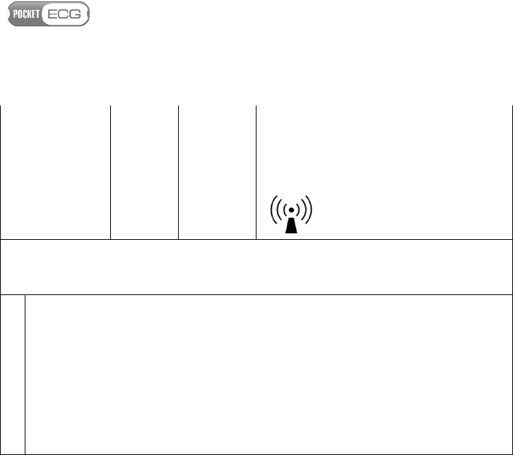
b
Interference may occur in the vicinity of
equipment marked with the
following symbol:
NOTE 1 At 80 MHz and 800 MHz, the higher frequency range applies.
NOTE 2: These guidelines may not apply in all situations. Electromagnetic propagation is
affected by absorption and reflection from structures, objects, and people.
a Field strengths from fixed transmitters, such as base stations for radio (cellular/cordless)
telephones and land mobile radios, amateur radio, AM and FM radio broadcast and TV
broadcast cannot be predicted theoretically with accuracy. To assess the electromagnetic
environment due to fixed RF transmitters, an electromagnetic site survey should be
considered. If the measured field strength in the location in which the PocketECG
transmitter is used exceeds the applicable RF compliance level above, the device should
be observed to verify normal operation. If abnormal performance is observed, additional
measures may be necessary, such as reorienting or relocating the recorder.
b Over the frequency range 150 kHz to 80 MHz, field strengths should be less than 3 V/m.
Page 59 of 118
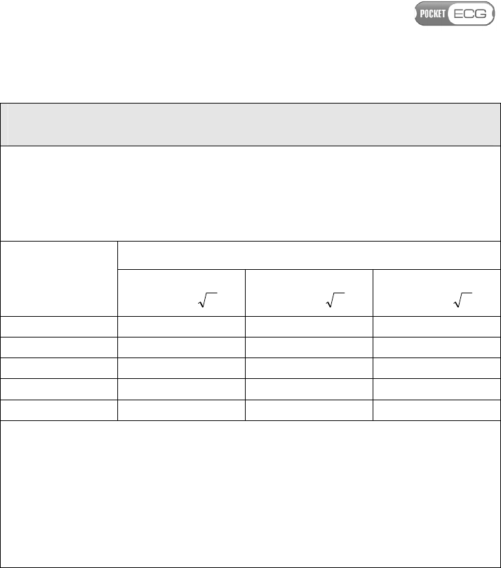
Recommended separation distances between portable and mobile RF
communications equipment and the PocketECG transmitter
The PocketECG transmitter is intended for use in an electromagnetic environment in which
radiated RF disturbances are controlled. The customer or user of the PocketECG transmitter
can help prevent electromagnetic interference by maintaining a minimum distance between
portable and mobile RF communications equipment (transmitters) and the PocketECG
transmitter as recommended below, according to the maximum output power of the
communications equipment
Rated maximum
output power of
transmitter
(W)
Separation distance according to frequency of transmitter (m)
150 kHz to 80 MHz
( )
Pd 17.1=
80 MHz to 800 MHz
( )
Pd 17.1=
800 MHz to 2.5 GHz
( )
Pd 33.2=
0.01 0.12 0.12 0.23
0.1 0.37 0.37 0.74
1 1.17 1.17 2.33
10 3.70 3.70 7.37
100 11.70 11.70 23.30
For transmitters rated at a maximum output power not listed above, the recommended
separation distance d in meters (m) can be estimated using the equation applicable to the
frequency of the transmitter, where P is the maximum output power rating of the transmitter
in watts (W) according to the transmitter manufacturer.
NOTE 1: At 80 MHz and 800 MHz, the separation distance for the higher frequency range
applies.
NOTE 2: These guidelines may not apply in all situations. Electromagnetic propagation is
affected by absorption and reflection from structures, objects, and people.

Page 60 of 118
B. POCKETECG PC CLIENT SOFTWARE
14. EQUIPMENT REQUIREMENTS
The PocketECG PC client software should be used with personal
computers or tablets with Microsoft Windows XP, Vista or 7 OS
installed. The PC/tablet should meet the following requirements:
• At least 1 GB of RAM (2 GB recommended),
• 1 GHz CPU (1,5 GHz recommended),
• Free space on HDD – at least 20 GB (40 GB recommended),
• Internet connection – at least 512 kbps (downlink).
15. INSTALLATION
In order to install the PocketECG PC Client software, the PC user is
required to have administrative rights. The installation wizard will
guide the user through the entire installation process which consists of
a few steps. It is recommended to close all running applications before
starting the installation. The PC client software is normally installed in
the Program Files folder, however the user may select alternative
directory. After user selects the destination folder, copying of the
PocketECG files starts. During this step the user will be requested to
accept installation of the following software packages that are
distributed along with the PocketECG program: VC++ 2008 SP1
redistributable, Windows Mobile Device Center, Microsoft J#
Redistributable and Adobe Reader. These packages are required for
proper PocketECG Client operation.
During the installation of the PocketECG PC Client, a Windows registry
entries are created which specify the server aliases along with their
specific configuration parameters. Each alias consists of its own name
and server parameters which are needed to establish a proper

Page 61 of 118
connection. One of them is set as default and is used for first login
action. Each installer is dedicated for one of the servers and normally
there should be no need to change the default alias. It is impossible to
create a new server alias using the PC Client software as all of them are
included in the installer. If there is such need, it is necessary to contact
service provider or a distributor of the PocketECG software.
16. DISTRIBUTION
The PC client application is distributed to users using either a
traditional method (DVD-R / CD-R), or electronically. The electronic
distribution process is through password protected access to a SSL FTP
server to obtain the installer.
17. OVERVIEW
The PC client application allows for managing the recording sessions
and reviewing the ECG data that was sent to the remote server by the
patient monitors. The PC client user is able to manage ongoing
sessions, review and modify the results of the ECG analysis and
generate reports which summarize the detection results. After
selecting a recording session in the Navigator window the user may
start reviewing the ECG and the labeled arrhythmias. The ECG data,
analysis results and application functions can be accessed through five
viewing modes:

Page 62 of 118
Navigator – main session’s manager window. Allows
for selecting a particular session, which can be
accessed through the following viewing modes:
Event View– contains a list of ECG events /
arrhythmias detected by the system
Full Disclosure – allows for viewing the ECG
waveform recorded during the monitoring
Trends – contains diagrams illustrating
variations of the averaged heart rate and other
ECG parameters
Impressions and Findings – notepad for entering
comments which will be included in the
generated reports
Reports– contains a list of reports which
summarize the analysis results
Garbage – folder containing deleted recording
sessions
Archive – folder containing archived recording
sessions
17.1. Communication with remote server
The PC Client application utilizes regular internet connection in order
to perform its functions. The application monitors the state of the
connection with the remote server. If connection cannot be established
or is disturbed the “No internet” warning is displayed in the upper left
corner of the screen. The internet connection is required only for
transferring ECG data between the PC Client application and the
remote server. Only those functions of the application that require
internet communication are disabled when the problems with internet
connection occurs. The user can still review the already downloaded
ECG data, review trends, generate reports, etc.
If "No internet" warning is displayed in the upper left part of the
screen, the user should verify the state of internet connection. In order
to do this, the user should run an internet browser and check whether
it is possible to connect with any server and visit popular websites.

Page 63 of 118
Following below instructions can be helpful in solving the problem
with the remote server communication.
• If the internet browser responds properly
o Check configuration of the firewall application installed on
the PC. The firewall application should allow PocketECG
Client to make outgoing connections. If there is no rule
already created for the PocketECG Client software, the
solution may be to create a rule allowing PocketECG Client
software to make outgoing connections.
o The PC Client stores information related to the connection
quality to remote server in log files. The log files with *.csv
extension are saved in LocalDataRoot\Log directory. In
order to verify the quality of communication with remote
server, open the log file using any spreadsheet application or
simple text editor. The sample of the log file is presented
below.

Page 64 of 118
Ping test at: 2011/Oct/19 10:15:20 AM
Ping test
duration: 60 s
alias successful
failed
avg
succ.
time (ms)
pings
above 200
ms (%)
quality
(%)
ma1x3 37
1
71.294 0.0 97.4
ma1x1516 37
1
71.101 0.0 97.4
intermountain 37
1
69.668 0.0 97.4
google 27
1
35.822 0.0 96.4
The last column of the table presents quality of
communication with the remote server. If the quality is low
(under 50%) for one or more of the servers, contact the
PocketECG service provider or distributor for assistance.
• If the internet browser cannot connect to any web page.
o Check whether all cables required for internet access are
properly plugged into the PC and internet outlet. If the PC
uses wireless access to the internet, verify that the wireless
functions of the PC are enabled.
o If the PC is a member of a local network, ensure that the
local network operates correctly and is connected to the
internet (check all devices like routers, access points, etc. )
o Use operating system utilities in order to diagnose the
problem:
press the right mouse button over the network icon
in the notification area, and then select “Diagnose and
repair”. Follow the instruction given by the operating
system.
open the Network Connections menu (Start→Control
Panel→Network and Internet→Network and Sharing
Center→Manage network connections). Follow the
instructions given by the operating system.

Page 65 of 118
If none of the abovementioned solutions help in establishing the
reliable communication with remote server, contact the PocketECG
provider or distributor for assistance.