Medtronic MiniMed 7700N Blook Glucose Transmitter User Manual MP6024979 012 b
Medtronic MiniMed, Inc. Blook Glucose Transmitter MP6024979 012 b
UserManual.wiki
>
Medtronic MiniMed
>
7700N User Manual
manual
Navigation menu
Upload a User Manual
Namespaces
Wiki Guide
HTML
PDF
Info
Views
User Manual
Discussion / Help
Navigation
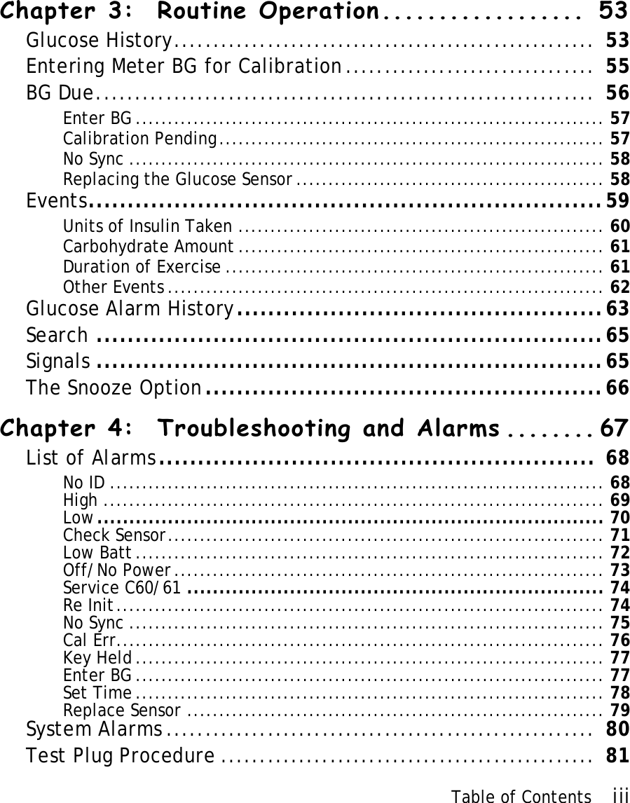

![Appendix 117 Table A2Guidance and Manufacturer’s Declaration - Electromagnetic ImmunityThe Guardian RT is intended for use in the electromagnetic environment specified below. The user of the Guardian RT should assure that it is used in such an environment.Immunity Test IEC 60601 Test Level Compliance Level Electromagnetic Environment - GuidanceConducted RFIEC 61000-4-6Radiated RFIEC 61000-4-3Not Applicable3 V/m80 MHz - 2.5 GHzNot Applicable3 V/mPortable and mobile RF communications equipment should be used no closer to any part of the Guardian RT than the recommended separation distance calculated from the equation applicable to the frequency of the transmitter.Recommended Separation DistanceNot Applicabled = 1.2 x square root[P] 80 - 800 MHzd = 2.3 x square root[P] 800 MHz - 2.5 GHzwhere P is the maximum output power rating of the transmitter in watts (W) according to the transmitter manufacturer, and d is the recommended separation distance in meters (m).Field strengths from fixed RF transmitters, as determined by an electromagnetic site surveya, should be less than the compliance level in each frequency range. Interference may occur in the vicinity of equipment marked with the following symbol: L](https://usermanual.wiki/Medtronic-MiniMed/7700N/User-Guide-629979-Page-123.png)
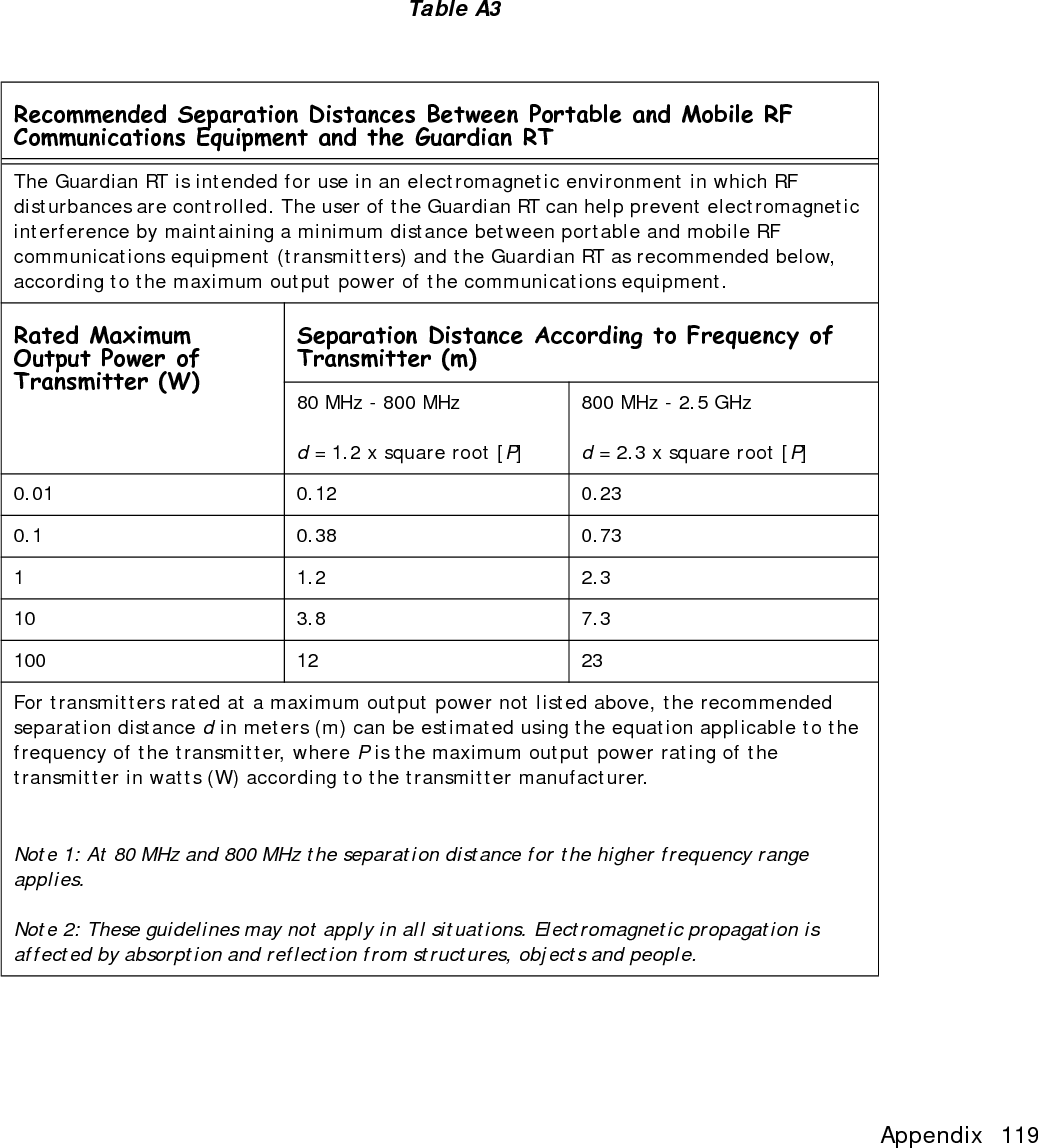
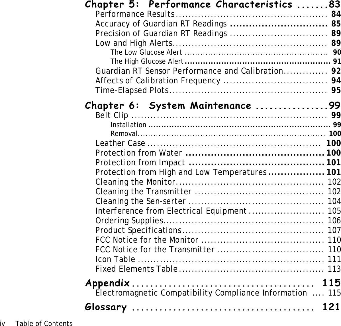
![Appendix 119 Table A3Recommended Separation Distances Between Portable and Mobile RF Communications Equipment and the Guardian RTThe Guardian RT is intended for use in an electromagnetic environment in which RF disturbances are controlled. The user of the Guardian RT can help prevent electromagnetic interference by maintaining a minimum distance between portable and mobile RF communications equipment (transmitters) and the Guardian RT as recommended below, according to the maximum output power of the communications equipment.Rated Maximum Output Power of Transmitter (W)Separation Distance According to Frequency of Transmitter (m)80 MHz - 800 MHzd = 1.2 x square root [P]800 MHz - 2.5 GHzd = 2.3 x square root [P] 0.01 0.12 0.230.1 0.38 0.7311.22.310 3.8 7.3100 12 23For transmitters rated at a maximum output power not listed above, the recommended separation distance d in meters (m) can be estimated using the equation applicable to the frequency of the transmitter, where P is the maximum output power rating of the transmitter in watts (W) according to the transmitter manufacturer. Note 1: At 80 MHz and 800 MHz the separation distance for the higher frequency range applies.Note 2: These guidelines may not apply in all situations. Electromagnetic propagation is affected by absorption and reflection from structures, objects and people.](https://usermanual.wiki/Medtronic-MiniMed/7700N/User-Guide-629979-Page-125.png)