Medtronic MiniMed 7701 TGMSIII User Manual Mp6025067 011 b
Medtronic MiniMed, Inc. TGMSIII Mp6025067 011 b
manual 7701
Paradigm®
522 and 722 Sensor Features
Caution - Investigational device. Limited by Federal law to investigational use.

© 2004, Medtronic MiniMed. All rights reserved.
This product is covered by U.S. Patent Nos. 6,551,276 and 6,554,798. Other U.S. and/or foreign patents may be pending.
Bolus Wizard™ is a trademark of Medtronic MiniMed.
Dual Wave™ is a trademark of Medtronic MiniMed.
Easy Bolus™ is a trademark of Medtronic MiniMed.
Square Wave™ is a trademark of Medtronic MiniMed.
BD Logic™ is a trademark of Becton, Dickinson and Company
Energizer® is a trademark of Eveready Battery Company.
Glucagon Emergency Kit® is a trademark of Eli Lilly and Company.
Paradigm® is a trademark of Medtronic MiniMed.
Paradigm Link™ is a trademark of Medtronic MiniMed.
The Link™ is a trademark of Becton, Dickinson and Company (Canada only)
Quick-serter® is a trademark of Medtronic MiniMed.
Quick-set® is a trademark of Medtronic MiniMed.
Silhouette® is a trademark of Medtronic MiniMed.
Sof-set® is a trademark of Medtronic MiniMed.
IV3000® is a registered trademark of Smith&Nephew, Inc.
Sen-serter® is a registered trademark of Medtronic MiniMed.
Guardian® is a registered trademark of Medtronic MiniMed.
6025067-011 01/05
REF MMT-522
MMT-722
Contents 1
Contents
Chapter 1 Introduction .................................................1
Assistance ................................................................................................. 1
Accessories ................................................................................................. 1
User safety ................................................................................................ 2
Indications ............................................................................................. 2
Contraindications ..................................................................................... 2
Warnings ............................................................................................... 2
Reservoir and infusion sets ...................................................................... 2
X-rays, MRIs and CT scans ....................................................................... 3
Transmitter ........................................................................................ 3
Precautions ........................................................................................... 3
Avoid extreme temperatures .................................................................... 3
Infusion sets and sites ............................................................................ 3
Sensor ............................................................................................... 4
Adverse reactions ........................................................................................ 4
Notice ....................................................................................................... 4
Insulin pump and Radio Frequency (RF) accessories ........................................... 4
Chapter 2 Programming your sensor ...................................7
Introduction ............................................................................................... 7
Sensor icons ........................................................................................... 7
Programming the sensor ............................................................................. 8
High glucose alarm .................................................................................. 8
High snooze feature ................................................................................. 9
Low glucose alarm ................................................................................... 9
Low snooze feature .................................................................................10
Alarm snooze ........................................................................................10
Cal reminder .........................................................................................11
BG units ...............................................................................................11
Transmitter ID .......................................................................................12
Missed data ..........................................................................................13
Review settings ......................................................................................13
2Contents
Chapter 3 Starting the sensor ...................................... 15
Introduction .............................................................................................. 15
Inserting the sensor ................................................................................... 15
The transmitter ......................................................................................... 20
Attaching the transmitter ..........................................................................20
Connecting the sensor to the transmitter .......................................................21
Starting the sensor ..................................................................................... 22
Enter meter BG ......................................................................................23
Chapter 4 Using your sensor ........................................ 25
Status screens .......................................................................................... 25
Reading your graphs ................................................................................... 26
Your glucose values ..............................................................................26
Your alarms .......................................................................................26
3 hour graph ..........................................................................................27
24 hour graph ........................................................................................27
Sensor alarm history .................................................................................. 28
Sensor update history ..............................................................................28
Review settings ......................................................................................29
Removing transmitter and sensor ................................................................... 30
Disconnecting the sensor from the transmitter .............................................30
Removing the transmitter .......................................................................30
Removing the sensor .............................................................................30
Storage and handling ................................................................................30
Sen-serter maintenance ............................................................................30
Chapter 5 Troubleshooting and alarms .............................. 31
Alarms .................................................................................................... 31
What to do ...........................................................................................32
Sensor alarm conditions .............................................................................. 33
Troubleshooting ......................................................................................... 37
Reconnect old sensor ................................................................................37
Find Lost Sensor ......................................................................................37
Icon table ................................................................................................ 38
Default settings ......................................................................................... 39

Introduction 1
Chapter 1
Introduction
Thank you for choosing Medtronic MiniMed as your partner in helping you gain better control of
your diabetes. The Paradigm® 522 and 722 pump combines the technology of the Guardian®
Continuous Glucose Monitoring system as well as the Paradigm Link™ Blood Glucose Monitor powered
by BD Logic™ Technology to provide not only insulin delivery but real-time glucose sensor values as
well.
This user guide is designed to help you understand the sensor features of your pump. We strongly
recommend that you work closely with your healthcare professional for a safe and complete pump
start.
Assistance
Medtronic MiniMed provides a 24-hour Product
Help Line for assistance. The Help Line is staffed
with technicians who are trained in the set-up
and operation of the pump and are able to
answer pump-related questions. When calling
the Help Line or your local Medtronic MiniMed
office, please have your pump and serial number
available. The phone number for the 24-hour
Product Help Line is also on the back of your
pump.
Accessories
➠Meter: Your pump can be used with the optional Paradigm Link™ Blood Glucose Monitor powered by
BD Logic™ Technology. You can program your pump to automatically receive your blood glucose (BG)
readings from this meter. When a BG reading is taken, the value is automatically transferred to the
pump and stored in its memory as a calibration point. The calibration point is used to calculate the
real-time sensor glucose values that are displayed. The data may then be downloaded to a
computer.
Department Telephone number
24-hour Product Help Line
(calls within the United
States)
800.646.4633
(800.Mini M ed)
24-hour Product Help Line
(calls outside the United
States)
818.576.5555
2 Chapter 1
➠Transmitter: The transmitter (MMT-7701) is a small oval disk that connects to the sensor and is
adhered to the skin with a medical dressing. It contains a battery, sensor electronics and a radio
frequency transmitter. When a sensor is attached to the transmitter, it automatically initializes the
sensor and begins to periodically transmit glucose data to the pump using a radio signal.
➠Sensor: The glucose sensor (MMT-7002) is a device that continuously measures glucose from your
subcutaneous tissue as an electronic signal, the strength of which is proportional to the amount of
glucose present. An introducer needle allows for subcutaneous insertion of the sensor.
➠ComLink: The Medtronic MiniMed ComLink (MMT-7304), if available, is used to download the pump
data to the diabetes management software installed in your computer via a serial communications
interface cable.
User safety
Indications
The Paradigm 522/722 pump system is indicated for the continuous delivery of insulin, at set and
variable rates, for the management of diabetes mellitus in persons requiring insulin. In addition, the
pump system is indicated for continuous periodic monitoring of glucose levels in the fluid under the
skin, and possible low and high blood glucose episodes. The pump displays real-time glucose values
and stores this data so that it can be analyzed to track patterns and improve diabetes management.
Pump history can be downloaded to a computer for analysis of historical glucose values.
The real-time glucose values provided by the Paradigm 522 and 722 pump are not intended to be
used directly for making therapy adjustments. Rather, they provide an indication that a confirmation
fingerstick measurement may be required. All therapy adjustments should be based on
measurements obtained using a home glucose monitor and not based on the value displayed by the
Paradigm 522 and 722 pump.
Contraindications
Pump therapy is not recommended for people who are unwilling or unable to perform a minimum of
four (4) blood glucose tests per day and to maintain contact with their healthcare professional.
Successful insulin pump therapy requires sufficient vision or hearing to allow recognition of the pump
signals and alarms.
Warnings
Reservoir and infusion sets
Use only the Paradigm reservoir and Paradigm infusion sets with your pump. The reservoir and
infusion sets are specifically designed for use with the pump. Use of non Medtronic MiniMed Paradigm

Introduction 3
reservoirs and/or infusion sets may reduce pump accuracy and hinder occlusion detection. Do not
modify your Paradigm reservoir or Paradigm infusion set.
Do not put any other drugs/medications inside your reservoir to use with this pump. Only insulin
that has been prescribed by your physician can be used in this pump.
X-rays, MRIs and CT scans
If you are going to have an X-ray, CT scan, MRI or other type of exposure to radiation, TAKE OFF
YOUR PUMP, METER, TRANSMITTER, and SENSOR, and remove them from the area.
NOTE - The Paradigm pump and transmitter are designed to withstand common electromagnetic
interference, including airport security systems.
Transmitter
The Transmitter should be removed if irritation or reaction to the Transmitter tape develops.
The Transmitter should be disconnected from the sensor while traveling on an aircraft, or if it
interferes with another transmitting device.
Precautions
Although the pump has multiple safety alarms, it cannot notify you if the set is leaking or the
insulin has lost its potency. It is essential, therefore, that you test your blood glucose levels at least
four times per day. If your BG is out of range, check the pump and the infusion set to ensure that the
necessary amount of insulin is being delivered.
Avoid extreme temperatures
1Avoid exposure of your pump and remote control to temperatures above 108°F (42°C) or below 34°F
(1°C).
2Insulin solutions freeze near 32°F (0°C) and degrade at high temperatures. If you are outside in cold
weather, wear your pump close to your body and cover it with warm clothing. If you are in a warm
environment, take measures to keep your pump and insulin cool.
3Do not steam, sterilize or autoclave your pump, transmitter, or sensor.
Infusion sets and sites
Avoid using an infusion site that will be irritated by clothing and accessories, or by rigorous
stretching and exercise.

4 Chapter 1
Sensor
Prior to exercising, make sure the sensor is firmly attached.
Adverse reactions
Operation of the sensor feature requires the insertion of a glucose sensor into the skin. Bleeding,
swelling, bruising, or infection at the sensor insertion site are possible risks of sensor use. The sensor
should be removed if redness, pain, tenderness or swelling develop at the insertion site. The
transmitter should be removed if irritation or a reaction to the transmitter tape develops. Contact
your doctor and the Medtronic MiniMed 24-Hour Product Help Line in the event of any adverse
reaction.
Notice
Insulin pump and Radio Frequency (RF) accessories
The pump, Paradigm Link meter, transmitter and remote control comply with the United States
Federal Communications Commission and international standards for Electromagnetic Compatibility.
Do not use the RF meter or the transmitter to send your BG reading to the pump while on an
aircraft. Manually enter your BG.
The transmitter should be disconnected from the sensor while traveling on an aircraft, or if it
interferes with another transmitting device.
These devices comply with Part 15 of the FCC Rules. Operation is subject to the following two
conditions: (1) This device may not cause harmful interference, and (2) this device must accept any
interference received, including interference that may cause undesirable operation. It does not
interfere with any radio frequency signals transmitted from outside sources.
These standards are designed to provide reasonable protection against excessive radio frequency
interference and prevent undesirable operation of the device from unwanted electromagnetic
interference. Operation is subject to the following two conditions:
1This device has been tested and found to comply with the regulations governing such devices in your
area. For the specific regulation and test results for your area, please contact the Medtronic
MiniMed 24-hour Product Help Line.
2This device generates, uses, and can radiate radio frequency energy and, if installed and used in
accordance with the instruction, may cause interference to radio communications. If the device
CAUTION: Any changes or modifications to the devices not expressly approved by
Medtronic MiniMed could void your ability to operate the equipment.
Introduction 5
does cause interference to radio or television reception, you are encouraged to try to correct the
interference by one or more of the following measures:
➠Reorient or relocate the insulin pump/remote control/Paradigm Link meter/transmitter
➠Increase the separation between the insulin pump/remote control/Paradigm Link
meter/transmitter and the device that is receiving/emitting interference
The Paradigm Link meter and transmitter sends information to the pump using radio frequency. If
other devices that use radio frequency are in use, such as cell phones, cordless phones and wireless
networks, they may prevent communication between the pump and the meter and/or the pump and
transmitter. This interference will not cause any incorrect data to be sent and will not cause any
harm to your pump, transmitter or meter. Moving away from or turning off these other devices may
allow communication. Refer to, “Troubleshooting and alarms” in the pump user guide to correct
interference problems you may have.
Wireless transmission between the pump and transmitter within the six-feet operating range may
be interrupted due to the transmitter cable orientation. Move the pump closer to the transmitter or
to another position. If a Lost Sensor alarm has occurred retry: Sensor Start > Find Lost Sensor.
If you have questions, please contact the Medtronic MiniMed 24-hour Product Help Line.
6 Chapter 1

Programming your sensor 7
Chapter 2
Programming your sensor
Introduction
This chapter describes how to program your pump to get it ready to accept sensor data. To
understand how to navigate through these screens refer to your Pump User Guide. For your reference
the sensor icons are described below.
Sensor icons
Using your pump - refer to the Pump User Guide (Paradigm 522/722 Infusion Pump User Guide) to
learn how to navigate through the pump screens.There are various icons that appear at the top of
your pump screen, like the time, battery and reservoir icons which are described in your pump user
guide. The icons described here appear if you are using the sensor. Alert and Alarm icons have the
same meaning as described in your pump user guide.
The sensor icon appears once the Sensor feature is turned on.
The sensor icon changes when the sensor is connected to the transmitter and communicating
with the pump.
8 Chapter 2
Programming the sensor
To set up the sensor feature, from the Home screen,
press
ACT, and do the following steps:
NOTE - The sensor features are programmed in the order described in this chapter.
Main Menu > Sensor> Sensor Setup > Edit Settings
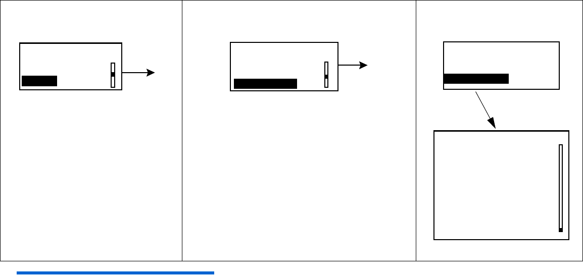
High glucose alarm
Your pump will alarm if your BG reaches or goes above what you set here. If you do not turn on the
High Glucose Alarm your pump will not alarm when your BG goes high.
1
Press
ACT
.
2Select On and press ACT. 3The EDIT SETTINGS screen
will appear. Press ACT to
program your High Glucose
limit.
4
Select
On
and press
ACT
.
5In the SET HIGH GLUCOSE screen, use the up
and down arrow buttons to set your limit.
Press ACT.
EDIT SETTINGS
Sensor: Off ACT
SENSOR ON/OFF
Off
On
ACT EDIT SETTINGS
Sensor: On
High Glucose: Off
Low Glucose: Off
ACT
HIGH GLUCOSE
Off
On
ACT
On
(flashing) set, then
press ACT.
SET HIGH GLUCOSE
200mg/dL
ACT
Programming your sensor 9
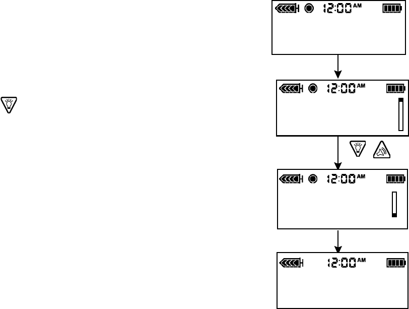
High snooze feature
Once you get a High Glucose Alarm, the pump alarms about every 5 minutes while the high glucose
condition exists, unless you set the High Snooze feature. This allows your glucose to return to normal
after you take some insulin without having the pump alarm about every 5 minutes. You can set the
time period for between 5 minutes to 3 hours.
Low glucose alarm
Your pump will alarm if your BG reaches or goes below what you set here. If you do not turn on the
Low Glucose Alarm, your pump will not alarm when your BG goes low.
6Press ACT to program
the High Snooze feature.
7Use the up and down arrow
buttons to select your High
Snooze alarm time and press
ACT.
8Press ACT to program your
Low Glucose limit.
9Select ON and press ACT.10 In the SET LOW GLUCOSE screen, use the up and
down arrow buttons to set your low glucose limit and
press ACT.
-
EDIT SETTINGS
Sensor: On
High Glucose: 200
High Snooze: 1:00
ACT
(flashing) set, then
press ACT
SET HIGH SNOOZE
1:00 ACT
EDIT SETTINGS
High Snooze 1:00
Low Glucose: Off
Alarm Snooze: 0:05
ACT
LOW GLUCOSE
Off
On
ACT
(flashing) set, then
press ACT.
SET LOW GLUCOSE
50mg/dL
ACT
10 Chapter 2
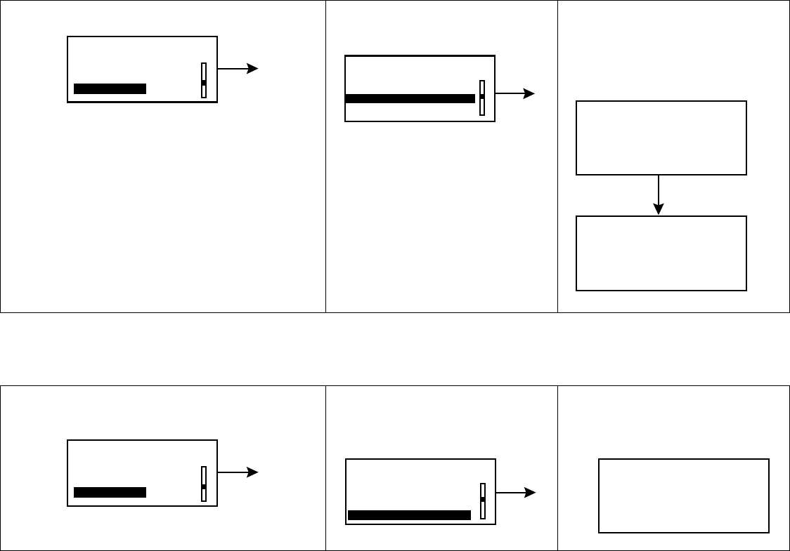
Low snooze feature
Once you get a Low glucose alarm, the pump alarms about every 5 minutes while the low glucose
condition exists, unless you set the Low Snooze feature. This option can be turned on during a
specific period of time when you are expecting your glucose level to fall below the set low limit. You
can set the time period for between 5 minutes to 1 hour.
Alarm snooze
This option allows you to set an alarm snooze for the Meter BG Now alarm(see Chapter 5,
Troubleshooting and Alarms for more information). So, instead of alarming every 5 minutes, they will
alarm at the time interval you set here. For example, if you set an Alarm Snooze of 20 minutes for
the Meter BG Now alarm, the alarm will only repeat every 20 minutes until you enter a Meter BG.
11 Low Snooze will be highlighted,
press ACT.
12 In the SET LOW SNOOZE screen, use the up and
down arrow buttons to set the time for your Low
Snooze alarm. Press ACT.
13 Alarm Snooze will be highlighted, press
ACT.
14 Use the up and down arrow buttons to set the
Alarm Snooze. Press ACT.
EDIT SETTINGS
Low Glucose: 50
Low Snooze: 0:20
Alarm Snooze: 0:05
ACT
(flashing) set, then
press ACT.
SET LOW SNOOZE
0:20
EDIT SETTINGS
Low Snooze 0:20
Alarm Snooze: 0:05
Cal Reminder 0:25
ACT
(flashing) set, then
press ACT
ALARM SNOOZE
0:05
Programming your sensor 11
Cal reminder
To help you remember to enter your meter BG readings for sensor calibration you can set the Cal
Reminder feature. To set your Cal Reminder:
BG units
You can select mg/dL or mmol/L as your Blood Glucose Unit (measurement type).
NOTE - This menu option will not appear if the Bolus Wizard feature is on.
15 Cal Reminder will be highlighted, press
ACT.
16 Use the up and down arrow buttons to set the time
and press ACT.
17 BG Units will be highlighted, press ACT.18 Select mg/dL or mmol/L and press
ACT.
EDIT SETTINGS
Alarm Snooze 0:05
Cal Reminder: 0:25
BG Units mg/dL
ACT
(flashing) set, then
press ACT
CAL REMINDER SET CAL REMINDER
0:25
Off
On
ACT ACT
EDIT SETTINGS
BG Units mg/dL
Transmtr ID: ------
Missed Data 0:30
ACT
BLOOD GLUCOSE UNITS
mg/dL
mmol/L
ACT
12 Chapter 2
Transmitter ID
The transmitter ID is found on the back of your transmitter. You need to enter your transmitter ID
so the transmitter and pump can communicate with each other.
19 Select Transmtr ID and
press ACT.
20 Use the up and down arrow buttons
to select each of the seven ID
numbers. Press ACT after each
entry. Press ESC when you are
done.
21 The EDIT SETTINGS
screen will appear.
Your Transmitter ID
will be highlighted.
EDIT SETTINGS
BG Units mg/dL
Transmtr ID: -------
Missed Data 0:30
ACT
- - -
(flashing) set,
then press ACT
SET TRANSMITTER ID
_ _ _ _ _ _ _
SET TRANSMITTER ID
1111111
Tip - To remember your transmitter ID,
write it down here ___________.
ACT
ACT
Transmtr ID
has been changed.
Please restart Sensor ACT
Programming your sensor 13
Missed data
The Missed Data feature allows you to set the period of time the pump will wait to alert you to
failed reception of sensor data from the transmitter to the pump.
Review settings
Main Menu > Sensor > Sensor Setup > Review Settings
The Review Settings feature allows you to review your settings to verify that they have been set as
you intended.
Select Review Settings now and verify that your settings are correct.
22 Select Missed Data and
press ACT.
23 Use the arrow buttons to set the
time, Press ACT.
24 When you have
completed the sensor
setup, press ESC until
the HOME screen
appears.
EDIT SETTINGS
BG Units mg/dL
Transmtr ID: 1111111
Missed Data 0:30
ACT
- - -
(flashing) set, then
press ACT
SET MISSED DATA
0:30 ACT
REVIEW SETTINGS
Sensor: On
High Glucose 200
High Snooze 1:00
Low Glucose: 50
Low Snooze 0:20
Alarm Snooze 0:05
Cal Reminder 0:25
BG Units: mg/dL
Transmtr ID: 1111111
Missed Data 0:30
14 Chapter 2

Starting the sensor 15
Chapter 3
Starting the sensor
Introduction
To start the sensor working you must complete the following steps in order.
➠Insert the sensor
➠Apply the transmitter
➠Connect the sensor to the transmitter
➠Perform “Sensor Start” on the pump
Inserting the sensor
The sensor is inserted through the skin with an insertion device called the Sen-serter® and placed
in the subcutaneous tissue. The sensor produces a signal that is proportional to the concentration of
glucose in the interstitial fluid at the insertion site. This signal is sent to the transmitter, which is
then sent to the pump. The pump translates the signal and displays a sensor reading on your pump
screen.
Choose a site with adequate subcutaneous
fat for sensor insertion. Shown below are
the body areas (shaded) that are best for
sensor insertion.
CAUTION: Never insert the sensor
within 2 inches from the
pump infusion site or
within 3 inches from the
manual injection site.
16 Chapter 3
Areas to avoid:
➠Frequently used injection or pump/sensor sites
➠Belt or waistline
➠2-inch area around navel
➠Site where clothing will rub or constrict
➠Scarred or atrophied tissue
➠Areas subjected to rigorous movement
➠Never insert the sensor within 2 inches from the pump infusion site or within 3 inches from the
manual injection site.
NOTE - Clean site with alcohol, making sure site is dry before inserting the sensor. Do NOT use
skin-preparation solutions prior to insertion. However, I.V. Prep may be used after insertion and
before applying a sterile dressing. Lift back of tape slightly to apply I.V. Prep.
Always refer to the instructions that shipped with your glucose sensor.
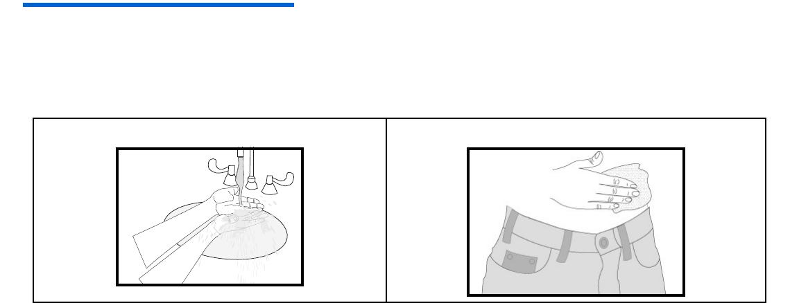
1Wash your hands. 2Clean and dry the sensor site.
Starting the sensor 17
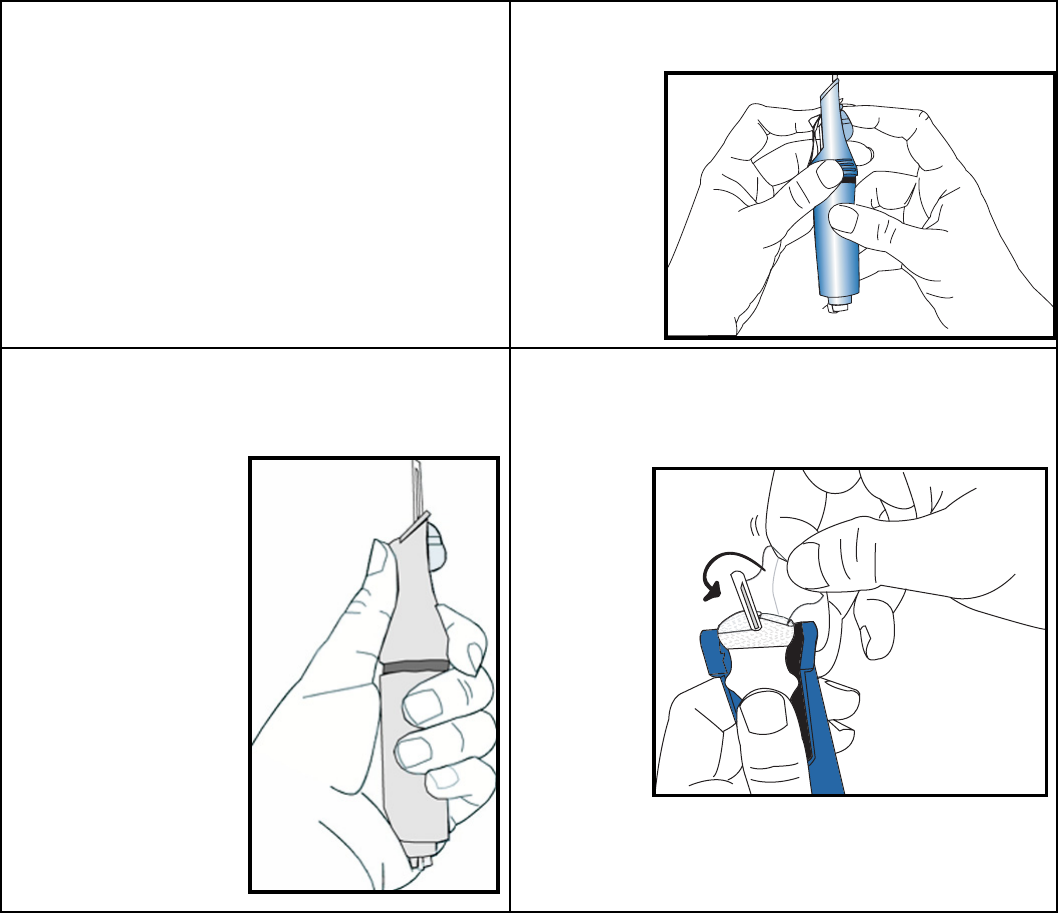
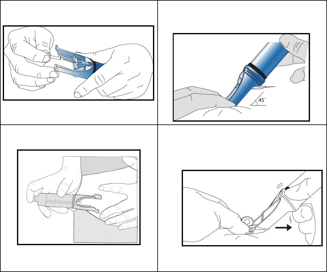
3Remove the sensor from package by
holding base or tape. Do not hold the
sensor by the introducer needle
handle.
4Place the sensor in the Sen-serter® until it
fits snugly.
5Place fingers on the back of the white
tape and push the carrier down until it
clicks into place.
6Holding the white tape as shown, remove
the clear tape using a counterclockwise
motion.
18 Chapter 3
7Turn the lock and remove needle guard
from introducer needle.
8Rest the Sen-serter legs on skin at 45 degree
angle, placing two fingers of opposite hand
on the Sen-serter legs to maintain angle.
9Press the white button to insert the
sensor.
10 Make sure the sensor is inserted and
flush with your skin.
11 While holding the sensor in place, gently
slide the Sen-serter away from the
sensor. Do not twist, bend or lift the Sen-
serter while removing from the sensor.
Starting the sensor 19
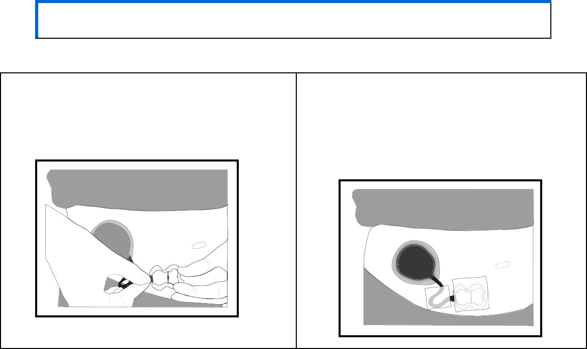
12 Holding the sensor base, remove the white paper from the adhesive pad. Press adhesive
against your skin.
13 Hold the sensor with two fingers on the base, and gently remove the introducer needle at
45-degree angle. Do NOT rotate introducer needle when removing. Dispose of needle in
sharps container.
NOTE - Bleeding will not affect the sensor’s performance.
14 Check the site for redness, bleeding, irritation, pain, tenderness or inflammation.
20 Chapter 3
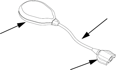
The transmitter
The Medtronic MiniMed Transmitter (MMT-7701) is a device that takes electronic signals generated
by the glucose sensor and sends them by radio frequency to the pump. The transmitter is attached to
the sensor by a sensor connector.
Attaching the transmitter
1Find a comfortable, protected area on the abdomen that is within cable reach to the sensor.
2Clean the area with isopropyl alcohol and allow to dry.
3Peel the paper from the Transmitter side of the adhesive pad.
4Stick the adhesive pad to the back of the Transmitter.
5Peel the paper from the skin side of the adhesive pad. Apply to skin by pressing firmly.
Tra n s mi t t er
Cable
Sensor Connector
Starting the sensor 21
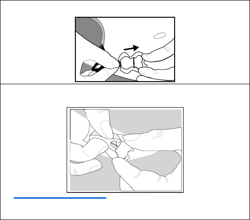
Connecting the sensor to the transmitter
CAUTION: In order to avoid damage, make sure the sensor and the cable are level
when attaching.
1Hold the sensor base while connecting the
cable. Do not squeeze clips. You should hear a
click when the cable and sensor connect. You
will also hear a short beep from the
transmitter.
2A prepping agent, such as an I.V. Prep may
be used to strengthen adhesion before
applying sterile dressing. Make sure smooth
side is down. The cable may be looped
under tape for strain relief. Apply a sterile,
transparent dressing such as an IV3000®
tape, over site.
22 Chapter 3
Starting the sensor
You are now ready to start your sensor so the sensor and the pump can communicate with each
other. To do this, follow the steps below:
NOTE - If screen times out, start again, DO NOT disconnect sensor.
1Press ACT from the HOME
screen. In the MAIN MENU,
select Sensor and press
ACT.
2Select Sensor Start, press ACT.3New Sensor will be
highlighted, press ACT.
4Connect your sensor now if you have not
already done so. Press ACT.
5Press ACT.
MAIN MENU
Bolus
Suspend
Sensor
ACT
SENSOR MENU
Sensor Update Hist.
Sensor Alarm History
Sensor Start
ACT
Reconnect Old Sensor
Find Lost Sensor
SENSOR START MENU
New Sensor ACT
NEW SENSOR
Connect new sensor,
then press ACT, or
ESC to abort
ACT
SENSOR READY 2 HRS
Alert will sound when
meter BG is required.
Press any key to cont.
Starting the sensor 23
Enter meter BG
After the two hour initialization period you must enter a BG reading into the pump to calibrate the
sensor. If you are using the Paradigm Link this will be done automatically with each fingerstick. To
enter a value manually perform the following steps.
1In the MAIN MENU, select
Sensor and press ACT.
2Select Enter Meter
BG, press ACT.
3Use the up and down arrow
buttons to enter your BG, press
ACT.
MAIN MENU
Bolus
Suspend
Sensor
ACT SENSOR MENU
Enter Meter BG
Sensor Update Hist.
Sensor Alarm History
ACT
(flashing) set, then
press ACT
ENTER BG
140mg/dL
ACT
24 Chapter 3

Using your sensor 25
Chapter 4
Using your sensor
Status screens
Your STATUS screens tell you what is going on in your pump. In the SENSOR STATUS screen you can
check the status of sensor information including when your next calibration will be needed, your
sensor’s age, and the state of your transmitter battery.
To get to your status screens:
The Sensor Status screen will only be available if the sensor feature has been turned on.
1From the HOME screen, press the ESC button
three times. This takes you to your pump
status screen.
2To see the Sensor Status screen, press ESC
one more time.
STATUS U100
Low Battery
Basal 1: 0.00 U/H
Reservoir Started:
Battery: Low
Fri 24 SEP 2004
S/N# 2222222
Paradigm 522
1.13 X.XX X.X
03SEP, 8:25A
Units Left: 173.1U
Time Left: > 24 hours
SENSOR STATUS
Next Cal: 8:30A
Sensor Age: 2d 3h
Sensor Isig: 123.45
Transmtr Batt: Good
Transmtr Ver: 1.1
Transmtr ID: 1111111
Pump S/N#: 2222222

26 Chapter 4
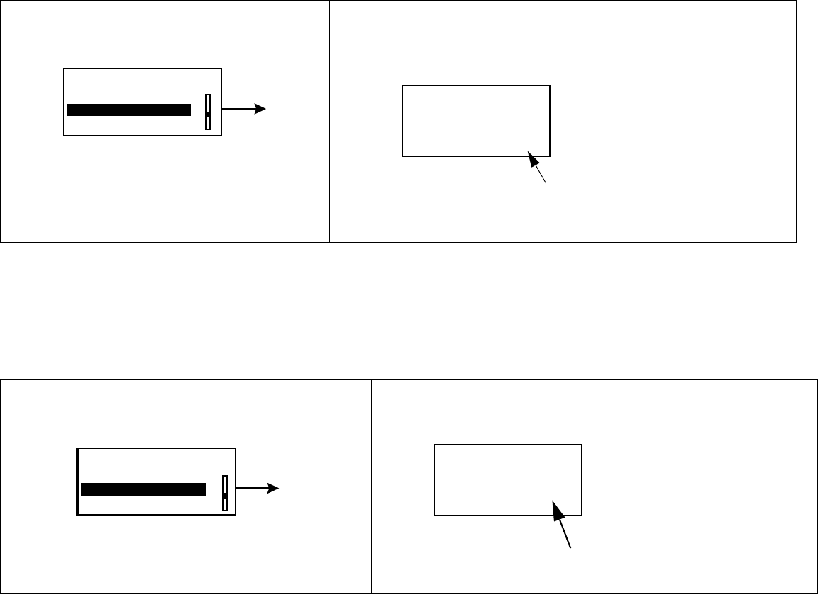
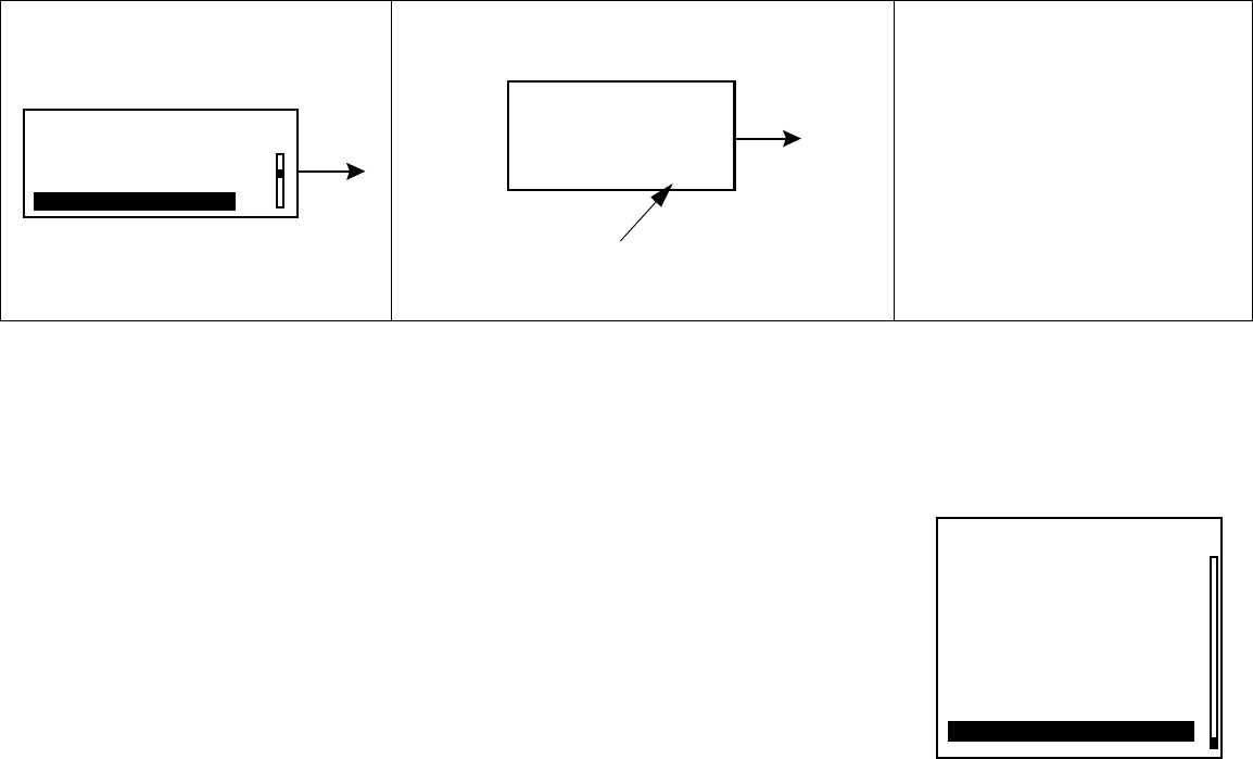
Reading your graphs
Once the sensor is calibrated you can view your sensor glucose values in real-time. To view your
current glucose and the most recent three hours of data press ESC once from the home screen, to
view the most recent 24 hours of data press ESC twice from the home screen.
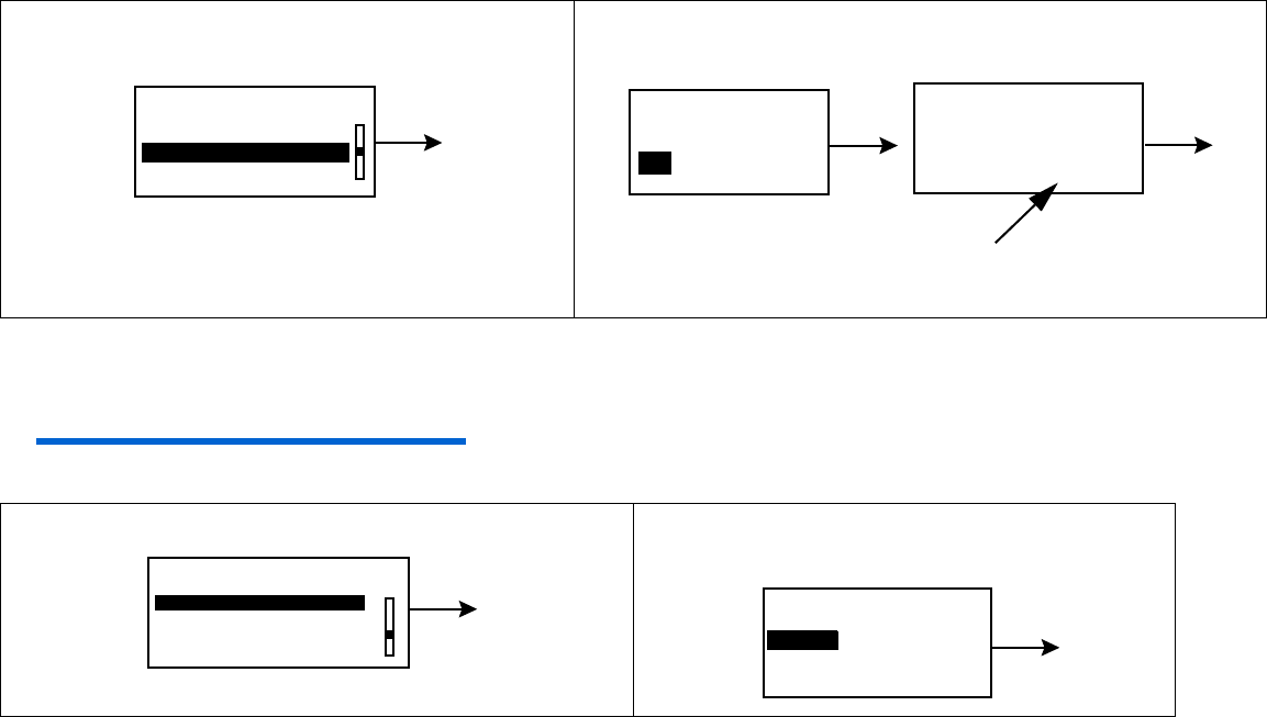
Your glucose values
Your glucose value will be shown on your graph. Each data point on the graph indicates your sensor
glucose. If an arrow is next to your sensor glucose:
➠An up arrow next to your glucose indicates that your glucose is rising at a rate of 1 to 2mg/dL
per minute for the last 20 minutes. Your glucose has changed by 20-40 mg/dL in the last 20 minutes.
➠A down arrow next to your glucose indicates that your glucose is dropping at a rate of 1 to
2mg/dL per minute for the last 20 minutes. Your glucose has changed by 20-40 mg/dL in the last 20
minutes.
➠Two up arrows next to your glucose indicates that your glucose is rising at a rate of more
than 40 mg/dL over the last 20 minutes.
➠Two down arrows next to your glucose indicates that your glucose has been dropping at a
rate of more than 40 mg/dL over the last 20 minutes.
Your alarms
The graph will also show any alarms that you received along with the time of the alarm. The alarms
you will see in your graph screens are:
For further information on these alarms, go to Chapter 5, Troubleshooting and Alarms.
➠Meter BG
➠Cal Error
➠Sensor End
➠Bad Sensor
➠Sensor Error
➠Weak Signal
➠Lost Sensor
Using your sensor 27
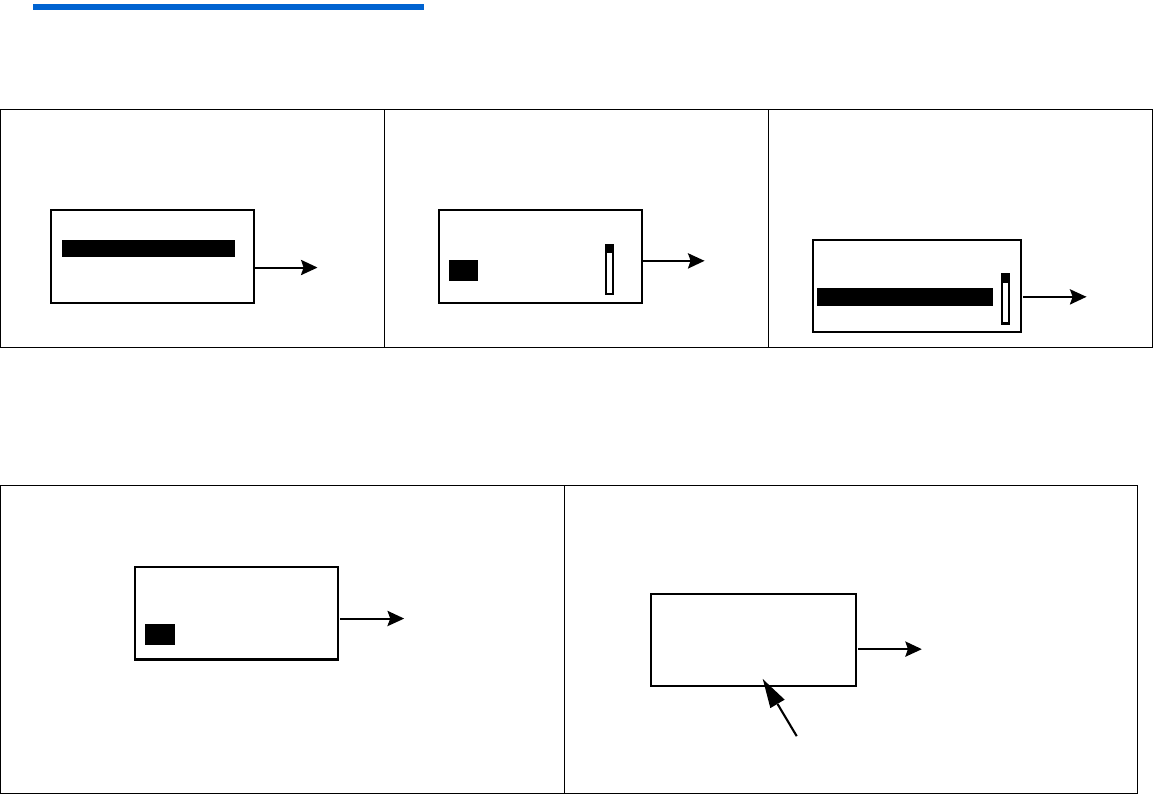
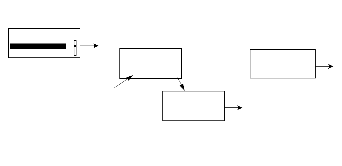
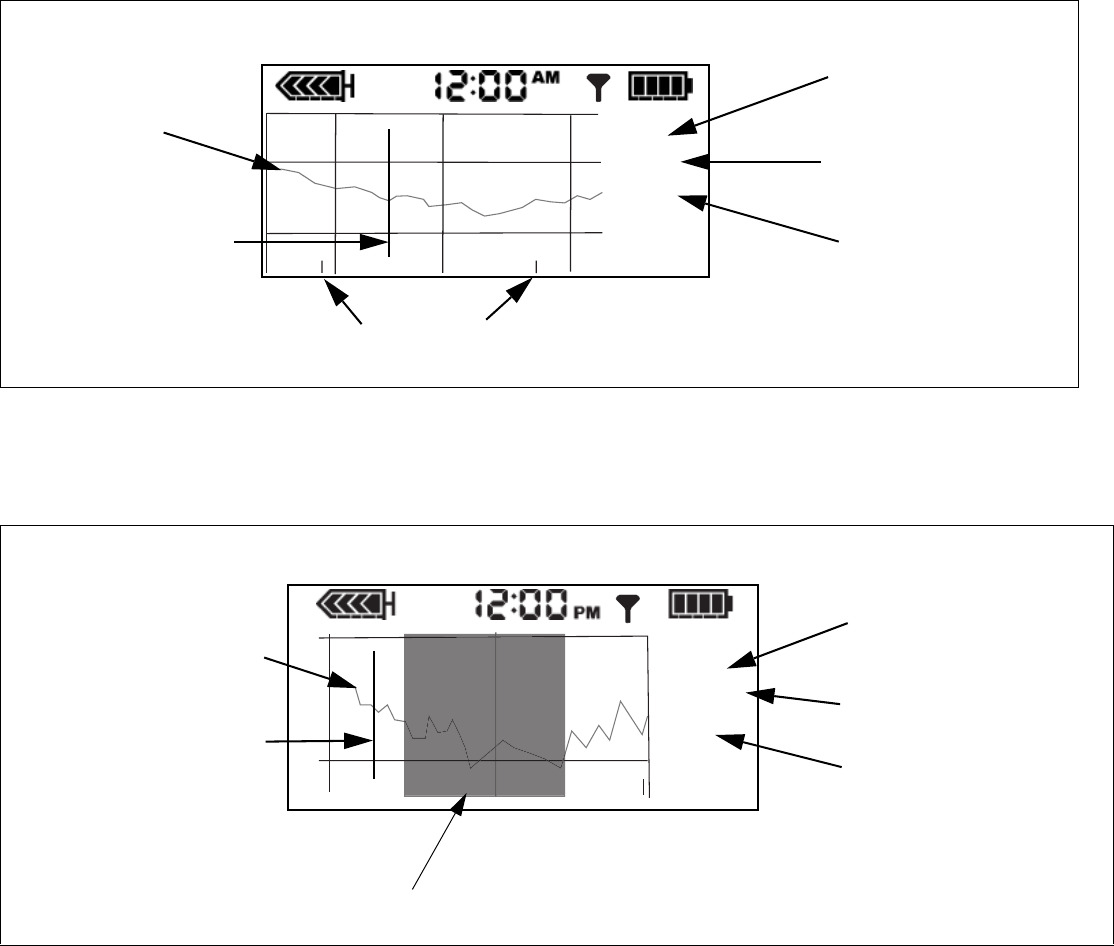
3 hour graph
To scroll through your sensor glucose data points and any alarms that you may have received press
the down button. Below is an example along with explanations of a screen you may see
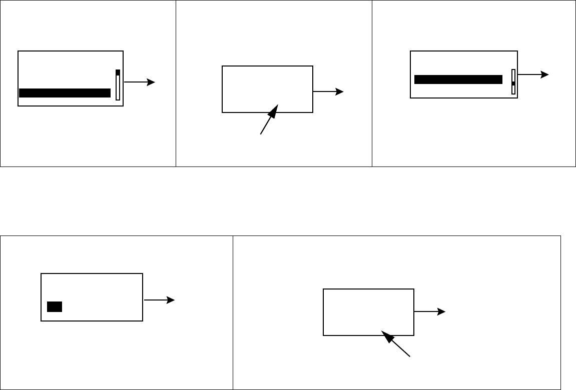
24 hour graph
To view the current glucose and a graph of the most recent 24 hours of data, from the HOME screen,
press ESC twice:
Time of BG or alarm.
Displays your sensor
glucose data or
alarm.
1 0 : 1 0 P
3 Hour
Sensor glucose
data points.
Flashing line
indicates each
sensor glucose or
alarm currently
being displayed.
150
The first time it will
say 3 hour, once you
scroll it will say
History.
Each time you bolus a marker
will appear on your graph
2 : 5 5 P
24 Hour
Time of BG or alarm.
The first time it will
say 24 hour, once you
scroll it will say
History.
Displays your sensor
glucose data or
alarm.
Sensor glucose data
points
Flashing line indicates
each sensor glucose
or alarm.
The darkened area is the 12 hours from 6:00pm to 6:00am.
150
28 Chapter 4
Sensor alarm history
Lists all of the sensor alarms that have occurred and will display up to 36 alarms. To view your
Sensor Alarm History:
Sensor update history
Lists all your calibration values entered into the pump. To view your Sensor Update History:
1In the MAIN MENU, select
Sensor and press ACT.
2Select Sensor Alarm History,
press ACT.
3The SENSOR ALARM
HISTORY screen will
appear.
1In the MAIN MENU, select
Sensor and press ACT.
2Select Sensor Update Hist., press
ACT.
3The SENSOR UPDATE
HISTORY screen will
appear.
MAIN MENU
Suspend
Sensor Calibration
Sensor
ACT SENSOR MENU
Enter Meter BG
Sensor Update Hist.
Sensor Alarm History
ACT SENSOR ALARM HISTORY
19OCT 10:45A Lo 70
19OCT 2:30P Hi 258
20OCT 6:53A Hi 250
MAIN MENU
Suspend
Sensor Calibration
Sensor
ACT SENSOR MENU
Enter Meter BG
Sensor Update Hist.
Sensor Alarm History
ACT SENSOR UPDATE HISTORY
20 OCT 11:41A 100
19OCT 5:45P 98
19OCT 2:30P 98
Using your sensor 29
Review settings
To review your sensor settings:
NOTE - If you do not turn on the High Glucose or the Low Glucose alarms then you will not see High
Snooze or Low Snooze listed under Review Settings.
1In the MAIN MENU, select
Sensor and press ACT.
2Select Sensor Setup, press ACT.3Select Review
Settings, press ACT.
MAIN MENU
Suspend
Sensor Calibration
Sensor
ACT SENSOR MENU
Sensor Alarm History
Sensor Start
Sensor Setup
ACT SENSOR SETUP
REVIEW SETTINGS
Edit Settings
Review Settings
ACT
Sensor: On
High Glucose: 200
High Snooze: 1:00
Low Glucose: 50
Low Snooze: 0:20
Alarm Snooze: 0:05
Cal Reminder: 0:25
BG Units: mg/dL
Transmtr ID: 1111111
Missed Data: 0:30
30 Chapter 4
Removing transmitter and sensor
Disconnecting the sensor from the transmitter
Hold the glucose sensor assembly in one hand and the sensor connector in the other hand. While
pinching the snap arms on the sides of the glucose sensor assembly together, gently pull the glucose
sensor assembly away from the sensor connector.
Removing the transmitter
Remove by pulling gently on the transmitter. Do not pull off by the sensor connector wire.
Removing the sensor
Remove the outer tape from over the sensor. Gently pull the sensor from your body. When removed
place in a sharps container.
Storage and handling
Store sensors in refrigerator at +2 to 10°C (+36 to +50° F). Do not freeze.
Prior to opening, allow the sensor package to reach room temperature and 5% to 95% humidity to
prevent condensation.
Sen-serter maintenance
Cleanse Sen-serter with soapy water, using liquid detergent or other household soaps. Allow to dry.
Disinfect Sen-serter by wiping with 10% bleach solution or 70% isopropyl alcohol.
Store Sen-serter in the released position to maintain optimum product performance and life.

Troubleshooting and alarms 31
Chapter 5
Troubleshooting and alarms
Alarms
Your pump has a sophisticated network of safety checks and systems. If the safety network detects
anything unusual, your pump notifies you of conditions that require your immediate attention. The
backlight illuminates the pump screen, and the alarm message displays on the screen. Alarms put the
pump in “Attention” mode.
NOTE - The STATUS screen shows any alarms that are active.
➠Why are alarms important?
Your pump monitors activities and notifies you if there is an unusual
pump status or your attention is required.
An alarm gradually becomes higher in volume until you turn it off.
If the vibrate mode is on, all alarms start as vibrations and then
change to beeps. For your safety, if there is no response within ten
(10) minutes, the beeps change to a siren. The pump will alarm with
a siren and/or a vibration every minute until the alarm is cleared. when a solid circle appears,
follow the instructions on the
screen.
32 Chapter 5
What to do
When an alarm is triggered, the pump goes into Attention mode, and an alarm message shows on
the screen. The pump then defaults to the HOME screen. Do these steps when you get an alarm:
1View the alarm:
From the HOME screen, press any button to see the alarm message.
2Read all of the alarm text. There are instructions on how to fix the
alarm condition. (Press to read more text, if available.)
3Clear the alarm:
Press ESC then ACT after you read the alarm instructions.
4The HOME screen appears.
5Follow the instructions that appeared with the alarm to fix the alarm
condition.
6Check your settings (i.e., time/date, basal, etc.) to make sure they are
correct.
(any button)
/
ALARM
MESSAGE
ESC, ACT
Alarm description and
instructions show
here.

Troubleshooting and alarms 33
Sensor alarm conditions
Listed below are the alarms that you may encounter while using the sensor feature of your pump,
along with how to resolve the alarm condition.
Weak signal
Alerts you when the pump does not receive valid data for a period of
time, as set in Missed Data. Move the pump to a new location on your body.
Lost sensor
The pump has not received a signal from the transmitter for more than 40
minutes. Make sure the transmitter and sensor are connected. If you hear a
beep you will have to recalibrate. Do NOT disconnect. To find your sensor
use the Find Lost Sensor function:
Main Menu > Sensor> Sensor Start > Find Lost Sensor
Low transmtr
Occurs when the transmitter battery is low. Replace transmitter. Need to
order new transmitter.
9:42A
Select Patterns
WEAK
SIGNAL
Sensor too far
away from pump
See user guide
ESC, ACT to clear
11:17A
LOST
SENSOR
Pump no longer
getting Sensor
data. See user
guide ESC, ACT to
clear
12:00A LOW
TRANSMTR
Replace
transmitter now
ESC, ACT to clear

34 Chapter 5
Bad transmtr
The transmitter battery is depleted. Replace transmitter.
Bad sensor
The transmitter has detected a bad sensor. Replace Sensor.
Sensor End
The sensor has reached the end of its life. Replace sensor. The sensor has a
life of about 72 hours which is about 3 days.
Cal error
Enter a new meter BG and try again. If error repeats, wait 10-15 minutes and
try again. If error repeats replace sensor.
Replace
transmitter now
ESC, ACT to clear
BAD
TRANSMTR
8:35A
10:05A
BAD
SENSOR
Replace Sensor
See user guide
ESC, ACT to clear
8:35A
SENSOR
END
Replace Sensor
See user guide
ESC, ACT to clear
3:36P CAL
ERROR
Invalid sensor data
or invalid BG value
See user guide
ESC, ACT to clear

Troubleshooting and alarms 35
Meter BG now
A meter BG is needed right away to update sensor and to keep receiving
sensor glucose data.
Meter BG by
A meter BG entry is required by the time that is shown to update sensor
and to keep receiving sensor glucose data.
Low mg/dl
The glucose value is lower than or equal to the low glucose limit set. If
you do not set a Low BG then you will not get a Low BG alarm.
High mg/dl
The glucose value is higher than or equal to the high glucose limit set. If
you do not set a High BG then you will not get a High BG alarm.
8:35A METER
BG NOW
Sensor reading
invalid Enter
meter BG now
ESC, ACT to clear
METER
BG BY 7:23 p
This is a reminder to
enter meter BG soon
ESC, ACT to clear
_:_
12:05A LOW
40 MG/DL
Glucose is lower than
user specified limit
ESC, ACT to clear
11:17A HIGH
200 MG/DL
Glucose is higher than
user specified limit
ESC, ACT to clear

36 Chapter 5
Sensor error
Sensor failed self-test. Press ESC then ACT to clear. You do not need to
change the Sensor. If the sensor fails self-test a second time you will get a
Bad Sensor alarm. If that occurs you will need to replace the sensor.
SENSOR
ERROR
Sensor failed self-
test See user guide
ESC, ACT to clear
_:_
Troubleshooting and alarms 37
Troubleshooting
Reconnect old sensor
You should only use this feature if you have disconnected the sensor and transmitter and have to
reconnect. For example, when flying on an aircraft.
Find Lost Sensor
If you receive a Lost Sensor alarm:
1Select Sensor Start, press ACT.2Select Reconnect Old
Sensor , press ACT.
3Reconnect Old Sensor
screen will appear.
Follow instructions and
press ACT.
1Select Sensor Start, press ACT.2Select Find Lost
Sensor, press ACT.
3Your sensor will be
ready in 15 minutes.
ACT
SENSOR MENU
Sensor Update Hist.
Sensor Alarm History
Sensor Start
SENSOR START MENU
Find Lost Sensor
ACT
New Sensor
Reconnect Old Sensorr
RECONNECT OLD SENSOR
Reconnect old sensor
then press ACT, or
ESC to abort
SENSOR READY 2 HOURS
Alert will sound when
meter BG is required.
Press any key to cont.
ACT
ACT
SENSOR MENU
Sensor Update Hist.
Sensor Alarm History
Sensor Start
SENSOR START MENU
Reconnect Old Sensor
ACT
New Sensor
Find Lost Sensor
SENSOR READY 15 MIN
Alert will sound when meter
BG is required.
Press any key to cont.
38 Chapter 5
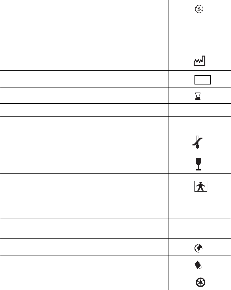
Icon table
Do not reuse:
Attention: See Instructions for Use
Method of sterilization using ethylene oxide:
Date of manufacture (year - month):
Batch code:
Use by: (year - month)
Catalogue number: REF
Device serial number: SN
Storage temperature range:
Fragile product:
Type BF equipment: (Protection from electrical
shock)
Pump: Conforms to IEC60601-1 sub-clause 44.6 and
IEC60529 standard. IPX7
Transmitter: Protected Against the Effects of
Continuous Immersion in Water. IPX8
Country:
Language of Instructions for Use:
Recycle:
w
r
LOT
Troubleshooting and alarms 39
Default settings
*Depending on your settings for High and Low Glucose, your limit ranges will vary.
Radio communication:
Menu Item Default
Setting
Limits
Sensor Menu: Sensor: Off
High Glucose: Off Low-400*
Low Glucose: Off 40-Hi*
Alarm Snooze: Off 0:05-1:00
BG Units: mg/dL
Cal Reminder Off 0:05-4:00
Missed Data 0:20 0:05-0:40
Low Snooze 0:20 0:05-1:00
High Snooze 1:00 0:05-3:00
40 Chapter 5
Glossary i
Glossary
A
Alarm Snooze - Once a sensor alarm occurs the
pump will not repeat the alarm until after this
period of time. This is the setting for the Meter
BG Now alarm.
B
BG Units - Blood glucose units used by the pump
(mg/dL or mmol/L). The BG units can only be
set from the sensor “Edit Settings” screen if the
Bolus Wizard is turned off.
C
Cal Reminder - The pump will trigger a Meter BG
Now alarm automatically every 12 hours,
signaling that the current calibration value is
no longer valid. The value of the Cal Reminder
is the amount of time before the current
calibration value expires when the user wants
to be reminded to calibrate by having the pump
issue a Meter BG Now alarm. For example, if
the Cal Reminder is set to 2 hours, the Meter
BG Now alarm will occur 2 hours before the
calibration is required.
H
High Glucose - The pump will alarm if the sensor
indicates that the user’s blood glucose is at or
above this value. You have the option to turn
this feature on or off.
High Snooze - Allows the user to set the delay
between the first High Glucose Alarm and any
subsequent alarms. This will allow the user to
avoid an alarm every five minutes until the
condition is corrected.
L
Low Glucose - The pump will alarm if the sensor
indicates that the user’s blood glucose is at or
below this value. You have the option to turn
this feature on or off.
Low Snooze - Allows the user to set the delay
between the first Low Glucose Alarm and any
subsequent Low Glucose Alarms. This will allow
the user to avoid an alarm every five minutes
until the condition is corrected.
M
Missed Data - The pump will alarm if it has not
received data from the sensor for an amount of
time that you set.
P
Pump S/N - Pump S/N is the serial number of the
pump currently in use.
ii Glossary
S
Sensor - Indicates whether the sensor feature is
On or Off.
Sensor Age - Sensor age is the amount of time,
in days and hours, since the sensor was first
inserted.
Sen-serter - The Sen-serter is indicated as an
aid for insertion of the Medtronic MiniMed
glucose sensor.
T
Transmtr Batt - The status of the transmitter
battery. Possible values are “Good,” “Low,” or
“Bad.”
Transmtr ID - The serial number of the
transmitter currently in use.
Transmtr Ver - The software version of the
transmitter currently in use.
Index 1
Index
Numerics
24-Hour Product Help Line,
contacting 1
A
Accessories 1
ComLink 2
meter 1
sensor 2
transmitter 2
Adverse reactions 4
Aircraft
flying with pump
FCC radio frequency rules 4
Alarm history
viewing for sensor 28
Alarm Snooze
setting 10
Alarms
bad sensor 34
bad transmtr 34
cal err 34
conditions for receiving 33
high mg/dL 35
how to respond 32
lost sensor 33
low mg/dL 35
low transmtr 33
meter BG by 35
meter BG now 35
sensor end 34
sensor error 36
understanding 31
weak signal 33
Assistance
24-Hour Product Help Line 1
Avoiding an insertion site 16
B
Bad sensor alarm 34
Bad transmtr alarm 34
BG
24 hour graphs 27
3-hour graphs 27
values in graphs 26
BG units 9
C
Cal 34
Cal err alarm 34
Calibration reminder
setting a Cal Reminder 11
Choosing an insertion site 15
Contraindications 2
F
FCC compliance
Part 15 of FCC Rules 4
Flying on an aircraft
FCC radio frequency rules 4
G
Graphs
24 hour 27
3 hour 27
sensor 26
H
Help Line, contacting 1
High Glucose alarm
setting 8
High mg/dL alarm 35
High snooze alarm
setting 9
History
review settings 29
sensor alarm, viewing 28
sensor updates, viewing 28
I
Icons on the pump
sensor communicating 7
sensor on 7
Indications 2
Inserting the sensor 15
choosing a site 15
Sen-serter 15
sites to avoid 16
2Index
L
Lost sensor alarm 33
Lost sensor data
Missed Data feature 13
Low 33
Low Glucose alarm
setting 9
Low mg/dL alarm 35
Low snooze alarm
setting 10
Low transmtr alarm 33
M
Meter 1
Meter BG by alarm 35
Meter BG now alarm 35
Missed Data feature
setting 13
N
Notice
radio frequency and FCC
compliance 4
P
Precautions
extreme temperatures 3
infusions sets and sites 3
sensor 3
Pump
alarms
how to responds 32
setting up Sensor feature 7
status screens 25
turning Sensor feature on 7
Pump icons
sensor communicating
Sensor on
how to know 7
sensor on 7
R
Radio frequency
FCC rules and compliance 4
Review Settings
viewing for sensor 29
RF features,
Paradigm Link meter 1
S
Sen-serter 15
Sensor
24 hour graphs 27
3 hour graphs 27
Alarm History, viewing 28
Alarm Snooze 10
alarms
bad sensor 34
bad transmtr 34
cal err 34
conditions for receiving 33
high mg/dL 35
how to respond 32
lost sensor 33
low mg/dL 35
low transmtr 33
meter BG by 35
meter BG now 35
sensor end 34
sensor error 36
understanding 31
weak signal 33
calibration reminder
setting Cal Reminder 11
graphs 26
High Glucose alarm 8
High snooze alarm 9
icons
sensor communicating 7
sensor on 7
Low Glucose alarm 9
Low snooze alarm 10
Missed Data feature
loss of sensor data 13
Review Settings 29
setting up feature on pump 7
startup procedure list 15
inserting the sensor 15
choosing a site 15
Sen-serter 15
sites to avoid 16
status screens 25
Transmitter ID 12
turning feature on 7
Update History, viewing
calibration values 28
Sensor communicating
how to know 7
Sensor End alarm 34
Sensor error alarm 36
Site
avoiding insertion in 16
choosing for insertion 15
Snooze alarms
setting 10
Start sensor
procedure list 15
inserting the sensor 15
choosing a site 15
Senserter 15
Index 3
sites to avoid 16
Status screens
pump 25
sensor 25
storage temperature, pump 38
supplies, ordering 2
T
Transmitter ID
setting 12
U
Update history
viewing sensor calibration
values 28
User Safety
adverse reactions 4
contraindications 2
indications 2
precautions 3
UserSafety
warnings 2
W
Warnings
reservoir and infusion sets 2
transmitter 3
X-rays, MRIs and CT scans 3
Weak signal alarm 33
4Index