Medtronic 19061 19061 User Manual SOCR System User Guide
Medtronic, Inc. 19061 SOCR System User Guide
UserManual.wiki
>
Medtronic
>
19061 User Manual
User Manual
Navigation menu
Upload a User Manual
Namespaces
Wiki Guide
HTML
PDF
Info
Views
User Manual
Discussion / Help
Navigation
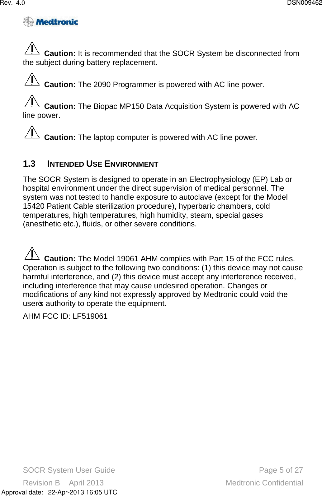
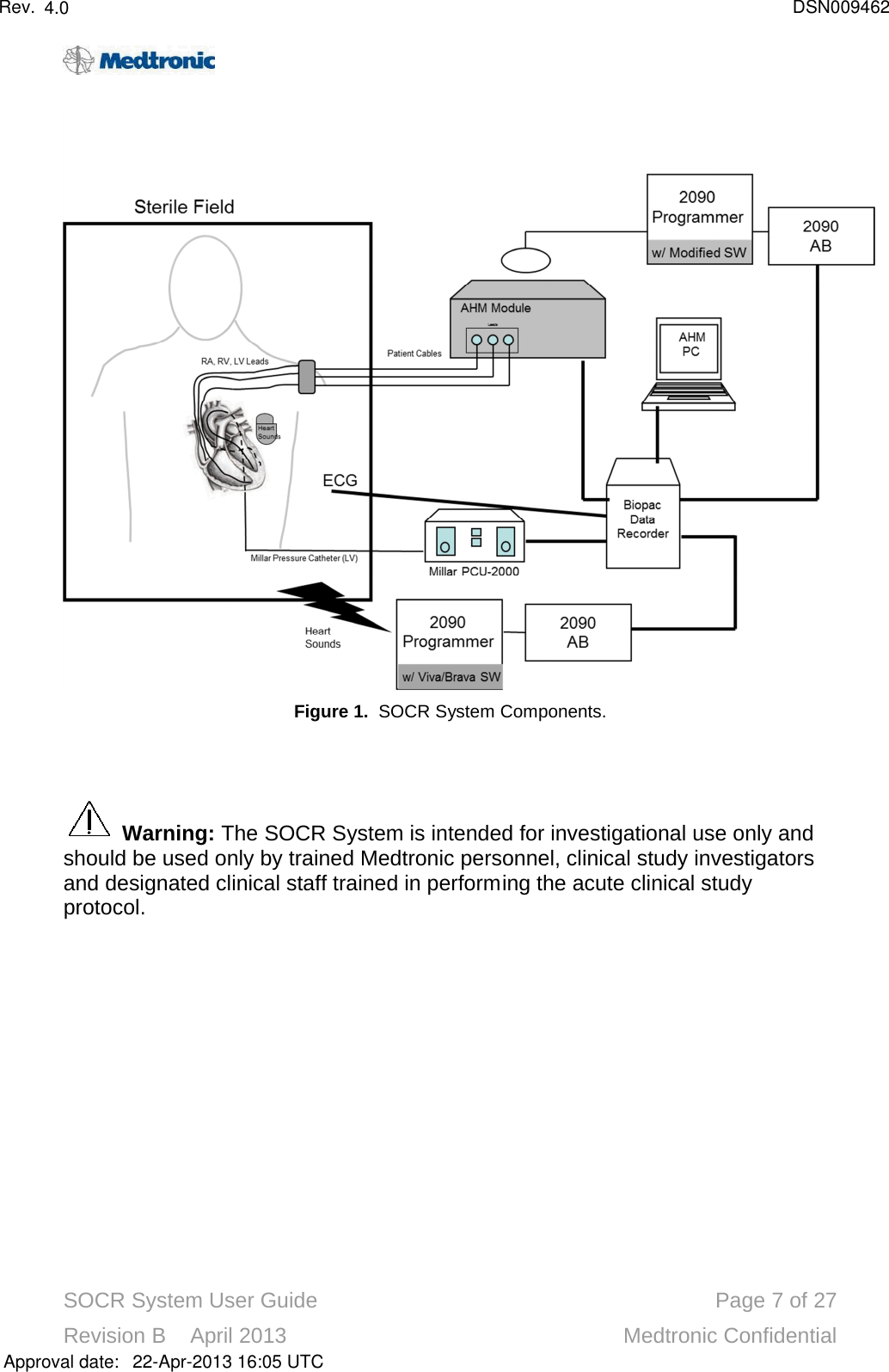
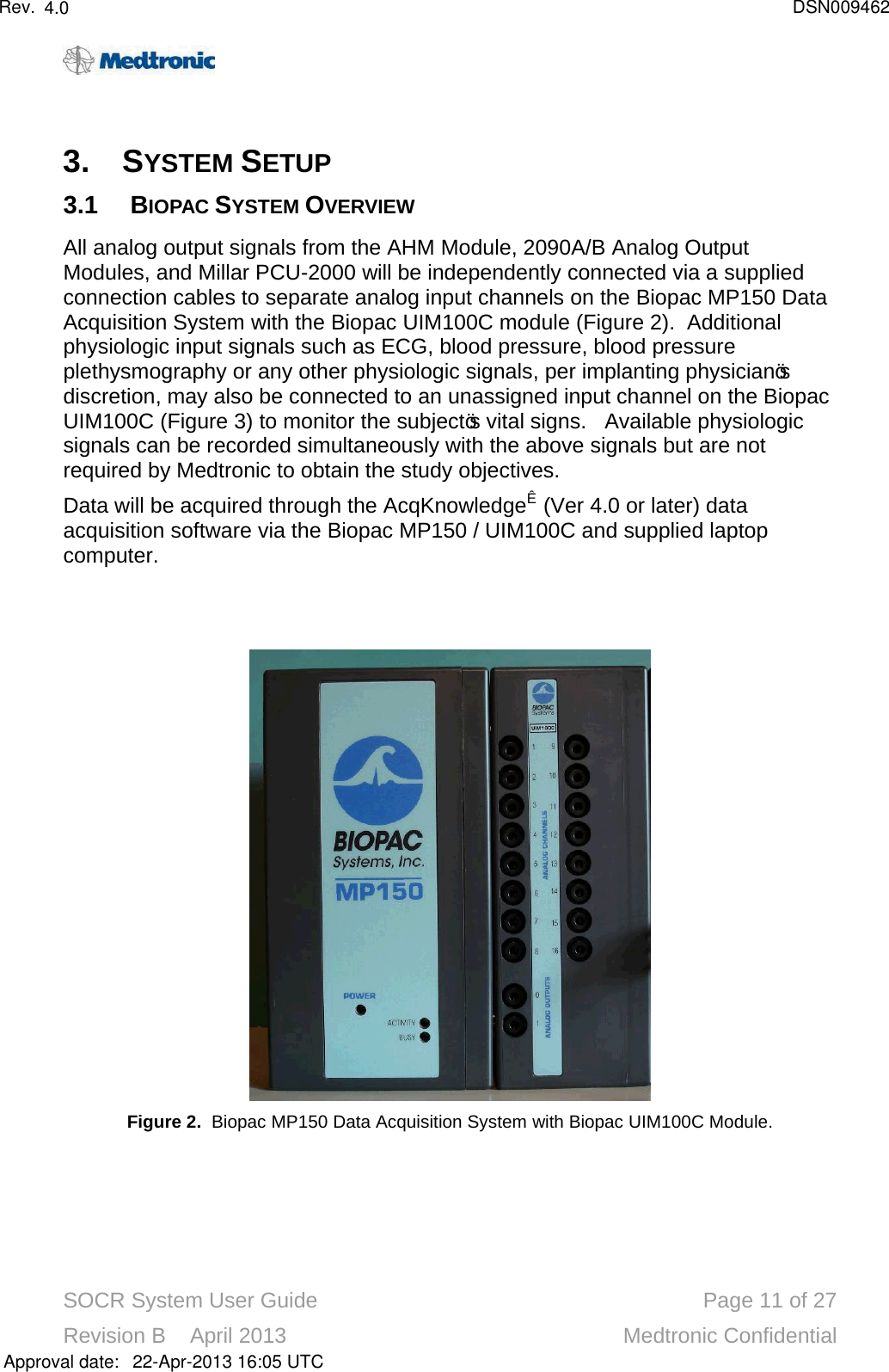
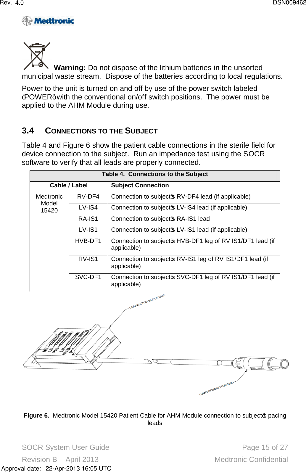
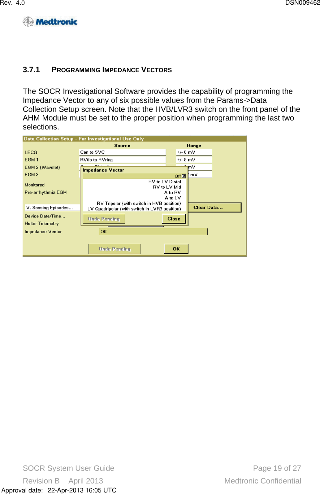
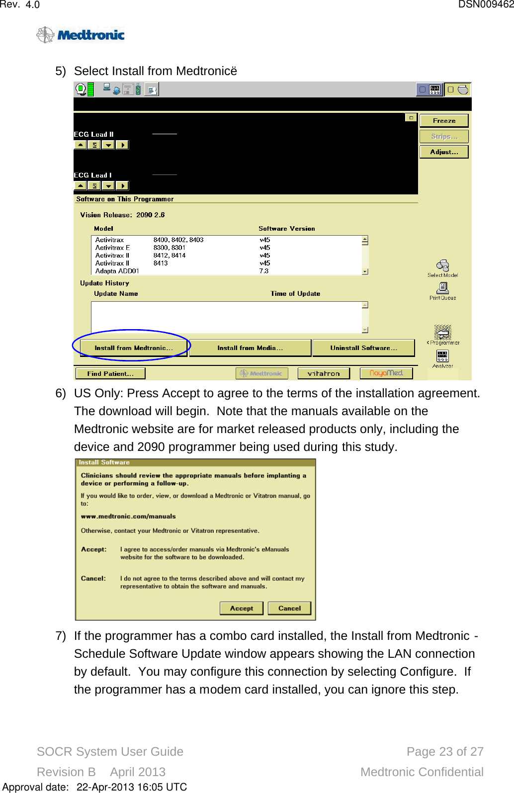
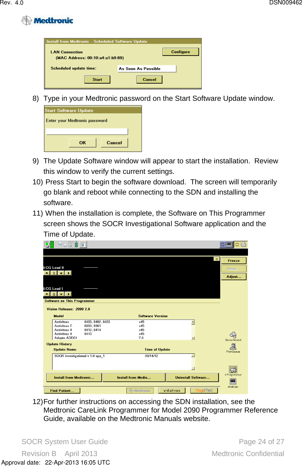
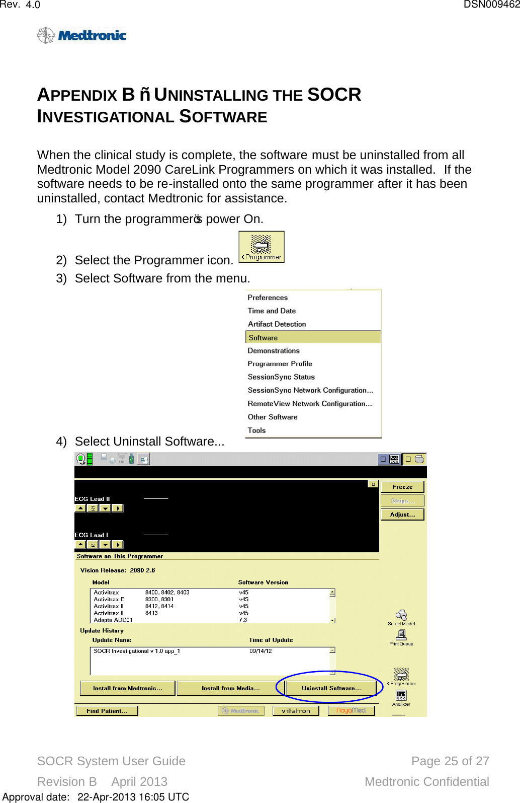
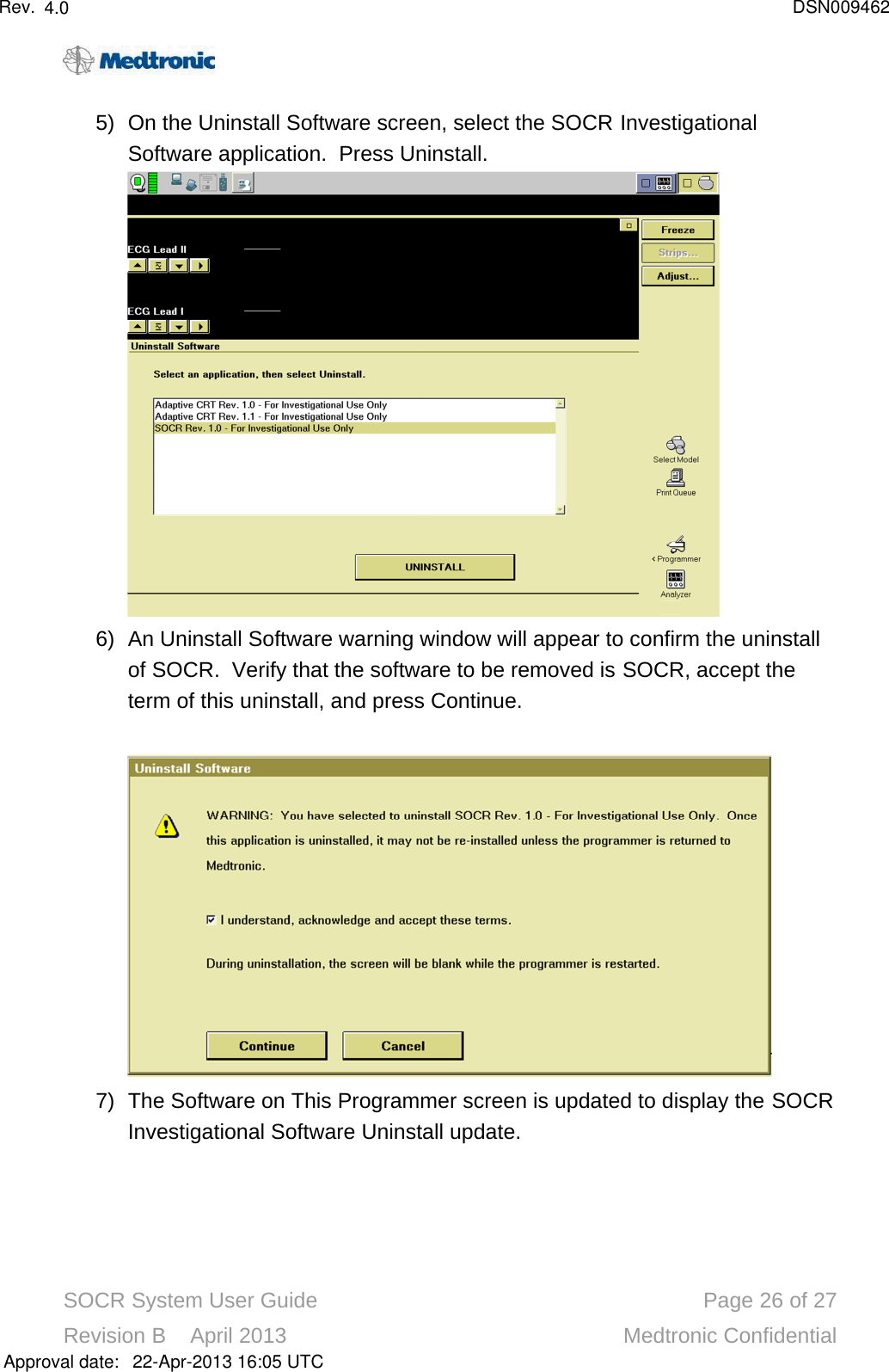
![SOCR System User Guide Page 6of 27Revision B April 2013 Medtronic Confidential2. SYSTEM OVERVIEW2.1 SYSTEM DESCRIPTIONThe SOCR System (Figure 1) contains electronics that control the continuous stimulation and sensing required to collect real-time intracardiac impedance and heart sounds signals. The impedance signals are collected from selected electrode vector configurations using the subject’s implanted pacing leads/LV catheter and an investigational impedance pacing unit, the Model 19061 Acute Human Monitor (AHM) Module. A Model 2090 programmer with the SOCR Investigational Software along with a switch on the front panel of the AHM Module allow the user to select specific electrode vector configurations for current stimulation and voltage sense measurement. The heart sounds signals are collected from an investigational Model 19062 Heart Sound Sensor Device placed on the subject. Real-time impedance and auxiliary signals from analog output terminals of the AHM Module, real-time heart sounds and EGM/marker signals from the two programmers through a 2090A/B Analog Output Module, and real-time LV pressure signals from the Millar PCU-2000 are transmitted to the applicable Biopac Data Acquisition System’s analog input terminals. The Biopac Data Acquisition System transmits the acquired analog input signals to the computer’s data acquisition software [AcqKnowledge®] which subsequently saves the data to the computer’s hard disk and displays real time waveform data on the computer’s display.The AHM Module also contains circuitry for standard pacing interventions with the implanted right atrial (RA) lead, right ventricular (RV) pacing lead, and left ventricular (LV) pacing lead or catheter. The leads are connected to an investigational Model 15420 Patient Cable in order to interface with the AHM Module. The LV catheter is directly connected.The Biopac MP150 Data Acquisition System also collectsphysiologic signals from standard EP laboratory equipment used for subject monitoring during device implant. These physiologic signals may include ECG, blood pressure, or other physiologic signals. Available physiologic signals can be recorded simultaneously with the above signals but are not required by Medtronic to obtain the study objectives.The SOCR system is shown pictorially in Figure 1. Approval date:4.0 DSN00946222-Apr-2013 16:05 UTCRev.](https://usermanual.wiki/Medtronic/19061/User-Guide-1987221-Page-6.png)