Medtronic 24967 24967 User Manual MAPS ID 502387 043
Medtronic, Inc. 24967 MAPS ID 502387 043
UserManual.wiki
>
Medtronic
>
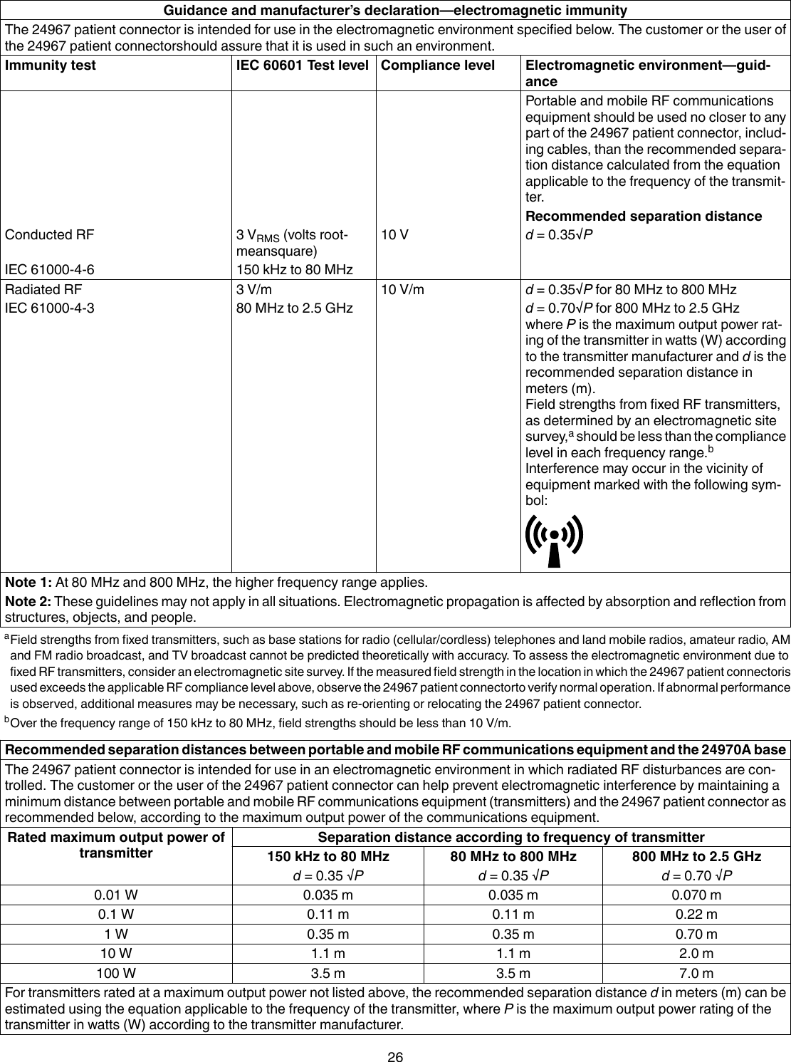
24967 User Manual
User Manual
Navigation menu
Upload a User Manual
Namespaces
Wiki Guide
HTML
PDF
Info
Views
User Manual
Discussion / Help
Navigation