Medtronic 24970A 24970A User Manual MAPS ID 502388 037
Medtronic, Inc. 24970A MAPS ID 502388 037
User Manual

CareLink SmartSync™ 24970A
Base
Technical Manual
Caution: Federal law (USA) restricts this device to sale by or on the order of a physician.
The following list includes trademarks or registered trademarks of Medtronic in the United States and possibly in other countries. All other trademarks are the property
of their respective owners.
CareLink, CareLink SmartSync, Conexus, Medtronic, Medtronic CareLink
Contents
1 Introduction to the 24970A Base .......................................................................... 4
1.1 Explanation of packaging and product symbols .......................................................... 4
1.2 Description ......................................................................................... 6
1.3 Intended use ....................................................................................... 7
1.4 Contraindications ................................................................................... 7
1.5 Warnings .......................................................................................... 7
1.6 Precautions ........................................................................................ 8
1.7 24970A base functions ............................................................................. 10
1.8 Regulatory compliance ............................................................................. 10
1.9 IT network, mobile device, and data information ........................................................ 10
2 Setup and configuration ................................................................................. 12
2.1 Contents of package ................................................................................ 12
2.2 System components ................................................................................ 12
2.3 Compatible accessories ............................................................................. 15
2.4 Setup ............................................................................................ 16
2.5 Connecting the base to the app ...................................................................... 19
2.6 Charging the patient connector battery ................................................................ 22
2.7 Troubleshooting potential interference ................................................................. 23
3 Conducting an Analyzer session ......................................................................... 24
3.1 Conducting an Analyzer session ..................................................................... 24
3.2 Delivering emergency VVI pacing ..................................................................... 25
3.3 Troubleshooting .................................................................................... 26
4 Maintaining the 24970A base ............................................................................ 27
4.1 Cleaning the 24970A base .......................................................................... 27
4.2 Specifications ..................................................................................... 30
5 Electromagnetic compatibility declaration ................................................................ 31
3
1 Introduction to the 24970A Base
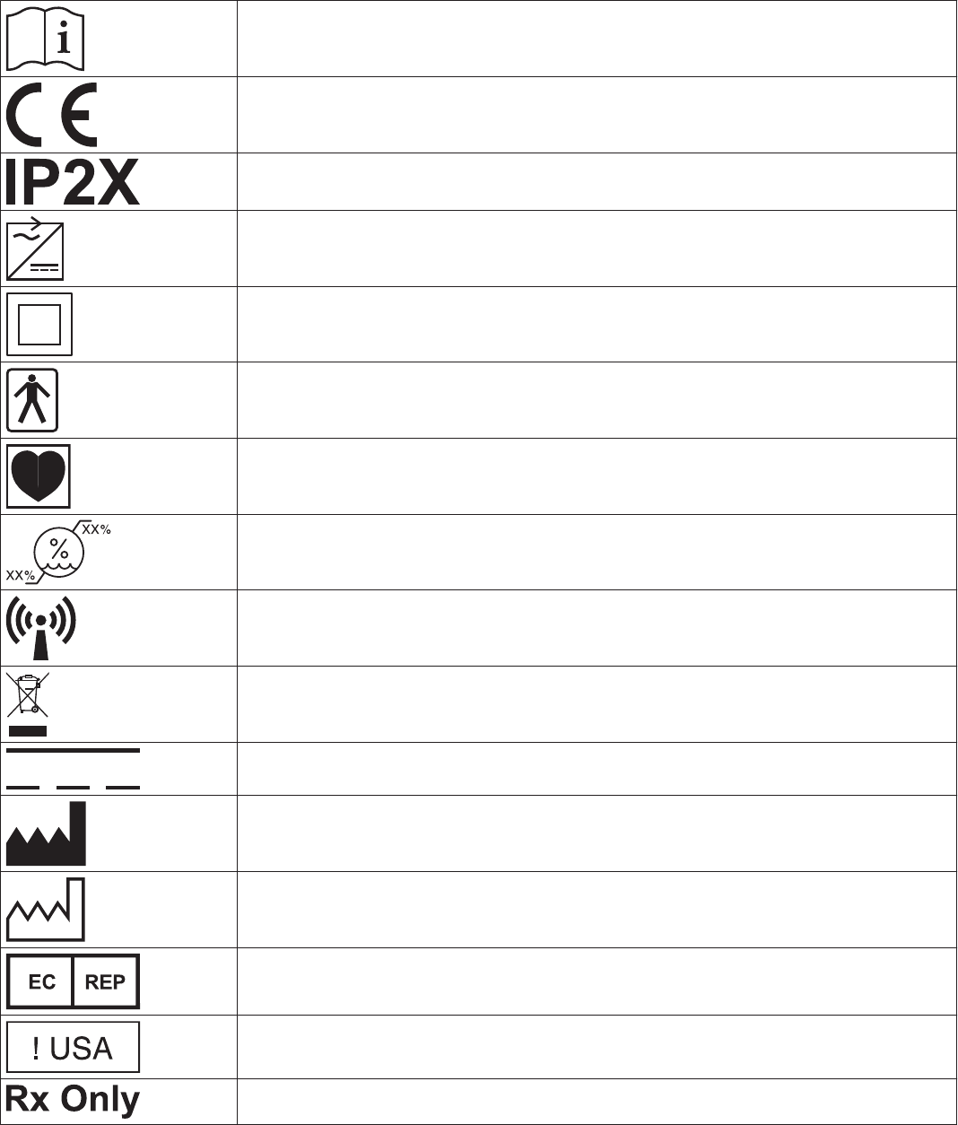
1.1 Explanation of packaging and product symbols
Refer to the package label and product to see which symbols apply to this product.
Consult instructions for use at www.medtronic.com/manuals.
Conformité Européenne (European Conformity). This symbol means that the device fully complies
with applicable European Union Acts.
Ingress protection
Use only with specified power supply
Class II ME equipment equipment
Type BF applied part
Type CF applied part
Humidity limitation
Non-ionizing electromagnetic radiation
Do not dispose of this product in the unsorted municipal waste stream. Dispose of this product
according to local regulations. See http://recycling.Medtronic.com for instructions on proper dis-
posal of this product.
Direct current
Manufacturer
Date of manufacture
Authorized representative in the European community
For US audiences only
Caution: Federal law (USA) restricts this device to sale by or on the order of a physician
4
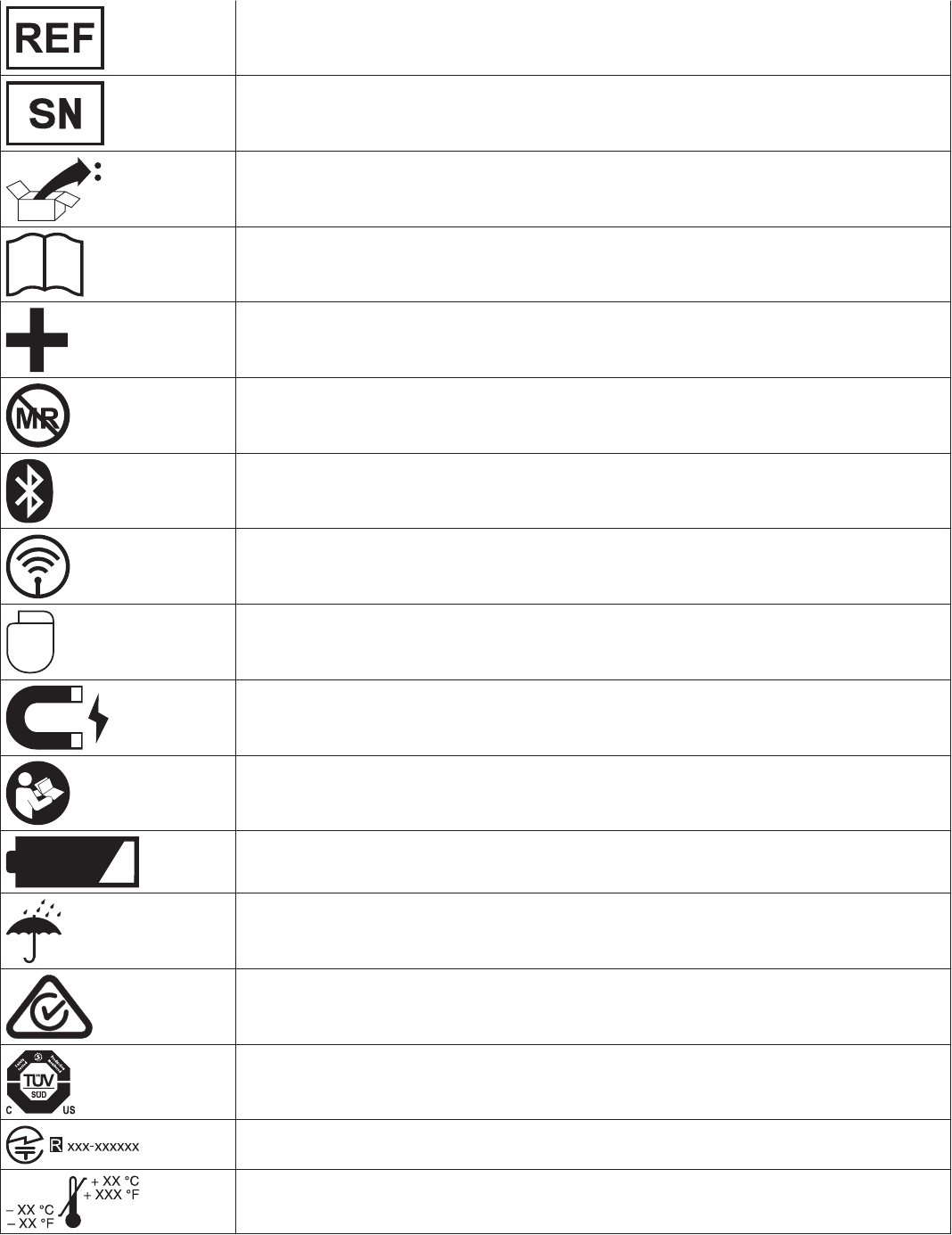
Re-order number
Serial number
Package contents
Product documentation
Accessories
Magnetic Resonance (MR) Unsafe
Bluetooth connection
Wireless communication enabled
Telemetry enabled
Caution: Strong magnet
Follow instructions for use (blue)
Low battery
Keep dry
ACMA (Australian Communications and Media Authority) and the New Zealand Ministry of Eco-
nomic Development Radio Spectrum Management compliance mark for Australia and New Zea-
land
System meets the applicable Canadian and U.S. IEC safety standards
Technical Conformity (Ministry of Internal Affairs and Communications) mark for Japan
Operating temperature
5
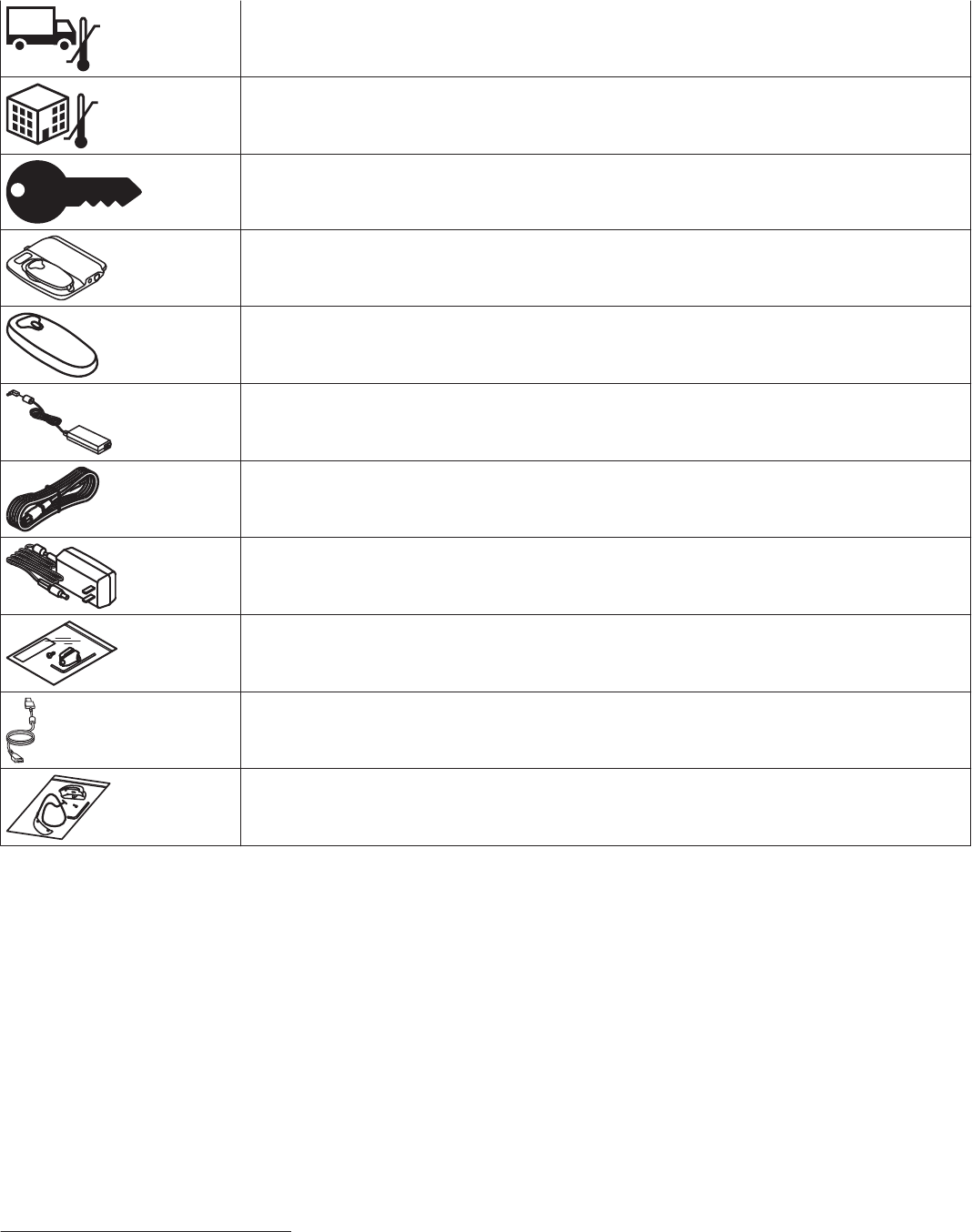
Transit temperature
Storage temperature
Security key
24970A Device manager
24967 Patient connector
249701 Power supply (for the 24970A base)
249705 Power cord (for the 24970A base)
249651 Power supply (for the 24967 patient connector)
249672 Tether Kit
249702 USB Cable
249671 Weight Kit
1.2 Description
The CareLink SmartSync Device Manager system (referred to from now on as the device manager system) is comprised of the Model
24970A Base, Model 24967 Patient Connector (also referred to as a telemetry head), and CareLink SmartSync Device Manager app
installed and running on your mobile device. The CareLink SmartSync Device Manager Base (referred to from now on as the base)
pairs with the Medtronic CareLink SmartSync Device Manager app on your mobile device to analyze the cardiac lead system for an
implantable Medtronic device.
The base includes these features:
• Analyzer hardware and patient cable connections to support electrical assessment of cardiac leads during implant.
• ECG cable connections to collect live cardiac waveform data that can be viewed, measured, and recorded using the app running
on your mobile device.
• Bluetooth® wireless technology to communicate with the app running on your mobile device.1
• A cradle to charge the Medtronic 24967 Patient Connector (referred to from now on as the patient connector).
• Optional USB connectivity to charge the patient connector.
1The Bluetooth® word mark and logos are registered trademarks owned by the Bluetooth SIG, Inc. and any such use of those marks by Medtronic
is under license.
6
1.3 Intended use
The base is intended to be used as part of the CareLink SmartSync device manager system. Clinicians use the base to analyze the
electrical performance of cardiac leads during device implant or invasive troubleshooting. Clinicians use the base’s ECG connections
along with the app display to view, measure, and record live cardiac waveforms.
The base is intended to be used by healthcare professionals only in operating environments under direct medical supervision.
1.4 Contraindications
The base is not intended for use as an external pulse generator (EPG) outside of the implant procedure. In addition, the patient’s age
and medical condition may dictate the lead analyses appropriate for the patient.
1.5 Warnings
These warnings apply in general to using the device manager system. For more information related to specific implantable device
models, see the reference guides for the implantable device and the software.
Battery replacement – The batteries that power the integrated Analyzer hardware in the base must be replaced every 2 years or
when they are depleted. Replace the batteries every 2 years or when the app indicates that the battery charge is low. Use of a failed
battery may reduce operating time and may cause user or patient injury.
Do not replace the battery while an Analyzer session is in progress or the base is connected to a patient. The battery connects to
circuitry which connects directly to the patient and could provide a low-resistance path to the myocardium for electrostatic discharge
(ESD) or leakage currents.
Changing polarity settings – Confirm the polarity capabilities of the cardiac lead system before changing polarity settings.
Changing polarity settings could result in loss of pacing if the cardiac lead system is not set up to facilitate pacing in the polarity
selected.
Cable connections – Connect all surgical cables, patient cables, and adaptors to the base before connecting the leads to the surgical
or patient cable. Ensure proper atrial or ventricular lead connections are made to the surgical or patient cables. For more information
on connecting surgical or patient cables to leads, refer to the instructions for use for the selected surgical or patient cable.
Connection of external devices – Additional equipment connected to medical electrical equipment must comply with the respective
IEC or ISO standards (for example, IEC 60950 for data processing equipment). All configurations must comply with the requirements
for medical electrical systems (see IEC 60601-1-1 or clause 16 of the 3rd edition of IEC 60601-1, respectively). Anyone connecting
additional equipment to medical electrical equipment configures a medical system and is therefore responsible that the system
complies with the requirements for medical electrical systems. Local laws take priority over the above mentioned requirements. If in
doubt, consult your local Medtronic representative or the technical service department.
Damage due to impact – Do not use the base if it has sustained impact damage. Internal components may be damaged or exposed.
Use of damaged equipment may impact user or patient safety.
DDD pacing mode – Do not operate the Analyzer hardware in the base in the DDD pacing mode when only the ventricular pacing
lead is connected. Interference detected at the unconnected atrial input of the Analyzer hardware can result in false sensing and can
drive the ventricular pacing rate to the Upper Rate setting.
Defibrillation/cardioversion – Whenever possible, for the safety of the patient, disconnect the base from the lead cardiac system
before defibrillating or cardioverting.
The Analyzer hardware in the base may be damaged by defibrillatory discharges when it is connected to an indwelling cardiac lead
system.
• The Analyzer hardware recovers normal operation within two seconds in the ventricle and within six seconds in the atrium for the
defibrillation test pulse defined in IEC 60601-2-31.
• The Analyzer hardware should be tested after being exposed to such charges.
Diagnostic ECG – Do not use the ECG display for diagnosis. Use a separate ECG device if diagnostic ECG capabilities are required.
Electric shock risk – Do not simultaneously touch the patient and any metal parts of the base (such as the USB port, power
connector, or patient connector charging contacts) as voltage may be present. Application of voltage to the patient may impact user
or patient safety.
Electrostatic discharge (ESD) – Discharge any static electricity from your body before touching the patient, the cable, the leads, or
the base. The pacing leads provide a low-impedance pathway to the heart.
Electrosurgical units (cautery) – Do not use electrosurgical units within 15 cm (6 in) of the cardiac lead system. Electrosurgical units
can cause tachyarrhythmias by inducing current on the leads.
Equipment compatibility – The device manager system should be used only for the assessment of implantable cardiac lead
systems for Medtronic-compatible implantable devices. Use of the device manager system with implantable devices from other
manufacturers may result in incompatible measurements. Medtronic does not accept responsiblity for measurements taken using the
device manager system with implantable devices from other manufacturers.
7
Flammable anesthetic mixture – The device manager system is not suited for use in the presence of a flammable anesthetic
mixture.
Handling inserted leads – Do not touch the exposed metal of the connector ends of the leads or the exposed metal of the cable clips
when handling inserted leads. Do not allow the exposed metal of the connector end of the leads or the exposed metal of the cable clips
to unintentionally contact electrically conductive or wet surfaces.
High output and maximum sensitivity – Avoid using high output (high amplitude and wide pulse width) and maximum sensitivity
simultaneously. This combination may result in over-sensing events, or sensing of paced events. The combination of high output and
maximum sensitivity may include the following effects:
• Use of high atrial sensitivity (low numerical settings) may allow ventricular potentials to inappropriately inhibit or trigger the atrial
output in the presence of large ventricular depolarization potentials or high output.
• High output and maximum sensitivity may result in opposite-chamber sensing of the pace output. The Analyzer hardware in the
base includes a safety pacing feature to prevent inappropriate inhibition of ventricular pacing due to far-field sensing.
• Use of high sensitivity in the ventricle may result in inappropriate inhibition of the ventricular output due to T-wave or myopotential
sensing.
Importance of instructions for use – Before conducting an Analyzer session, Medtronic recommends that you take the following
actions:
• Read the CareLink SmartSync Device Manager product instructions for use for information about using the device manager
system to assess the electrical performance of Medtronic implantable device cardiac lead systems.
• Thoroughly read the instructions for use for the leads used with the implantable device.
• Carefully assess the patient’s condition and pacing system used to determine the appropriate parameter values to use during lead
analysis.
The instructions contained in this guide are liminted to the mechanics of setting up the device manager system and selecting the
correct options for the desired lead assessment tests. Improper use of the device manager system could result in erroneous or
inadvertent pacing and improper operation of telemetry and measurement functions.
Line-powered equipment – During lead implantation and testing, use only battery-powered equipment (or line-powered equipment
specifically designed for this purpose) to protect against fibrillation that may be caused by alternating currents. Line-powered
equipment used in the vicinity of the patient must be properly grounded. Lead connector pins must be insulated from any leakage
currents that may arise from line-powered equipment. An implanted lead forms a direct, low-resistance current pathway to the
myocardium.
Magnetic resonance (MR) unsafe – The device manager system is MR Unsafe. Do not bring any components of the device
manager system into Zone 4 (magnet room), as defined by the American College of Radiology.
Modification of equipment – Do not modify any hardware or software component of the device manager system. Modifications may
reduce system effectiveness and impact user or patient safety. Modifying any component without the approval of Medtronic could void
the user’s authority to operate the equipment.
Prolonged power loss – Connect the patient to an external temporary pacemaker in the event of a prolonged power loss of more than
five minutes.
Rapid atrial stimulation – Have defibrillation equipment readily available during rapid atrial stimulation. Use of high rates in the
atrium can result in high-rate conduction to the ventricle. Accidental high-rate stimulation of the ventricles may result in ventricular
tachycardia or fibrillation.
Radio-frequency (RF) interference – Portable and mobile RF communications equipment can interfere with the operation of
components of the device manager system. Although the device manager system has been approved, there is no guarantee that it
will not receive interference or that any particular transmission from this system will be free from interference.
Supply mains with protective earth – To avoid the risk of electric shock, connect the power supply only to a hospital-grade supply
mains receptacle with a protective earth. The third conductor in the power cord plug is a functional earth connection.
Temporary pacing – Do not leave the patient unattended when the Analyzer hardware in the base provides external pacing. The
Analyzer is a diagnostic device. If prolonged external pacing is needed, move the patient to an external pulse generator.
1.6 Precautions
Autoclaving – Do not autoclave the device.
Base and power cord positioning – Position the base and its power cord so that the cord can be easily accessed and disconnected.
Route all cords away from trafficked areas or secure them to prevent accidental tripping or kicking. The power cord is heavy and may
pull the base from the table, causing damage to it. If needed, secure the power cord to the table with tape, gauze, or a clamp. If it is
necessary to disconnect the base from the AC power mains, the power cord is the power disconnect at the mains outlet.
Damaged equipment – Periodically, inspect the base, its case and connection ports, and all cords and cables for damage. If the base
is cracked or if any of its connectors are damaged, contact your Medtronic representative. Replace the power supply if there is damage
8
to it, the power cord, or the wall plugs. Replace any accessory cables if the insulation or plug is damaged. Dispose of the damaged
part according to local regulations or return the part to Medtronic.
Do not immerse – Take care to prevent liquid from entering the base. Do not immerse the base or any accessories in any liquid or
clean them with glycol ethers or aromatic or chlorinated hydrocarbons.
Electrical and patient safety – The CareLink SmartSync Device Manager system is compliant with the requirements of UL/CUL/EN
60601-1 for electrical and patient safety.
Electrode quality – Use of high-quality silver/silver chloride (Ag/AgCl) electrodes can minimize the occurrence of small DC voltages
that can block the ECG signal. Use electrodes that are fresh and from the same box. Prepare the patient’s skin according to the
directions provided with the electrodes.
Electromagnetic interference (EMI) – The base has been tested for compliance with industrial and medical EMI regulations. Any
use outside the patient environment may result in malfunction.
Avoid excessive levels of EMI when working with Analyzer functions, if possible. At high sensitivity settings and in the presence of
excessive levels of interference, the Analyzer may inhibit completely or revert to asynchronous pacing operation, pacing at the lower
rate.
The following list includes sources of excessively strong EMI that may temporarily affect the operation of the Analyzer hardware in the
base:
• Electrosurgical equipment
• Diathermy equipment
• Some medical telemetry equipment (when operated within 1 m [about 3 feet] of the base)
• Communication transmitters such as cellular phones and “walkie talkies”
Finger injury – To avoid a painful pinch, do not place fingers in the hinge area when lifting or closing the base lid.
Maintenance and service – Do not modify or do any maintenance or service on the base while you are using it. Doing any of these
tasks on the base while it is in use can lower its effectiveness. Contact Medtronic if your base is not working properly.
Magnetic interference – The base includes a magnet under the charge cradle to secure the patient connector and ensure charging.
The symbol on the cradle identifies the location of this magnet. Avoid placing devices or material that may be damaged by the
magnetic field (such as magnetic media, watches, or other electronic devices) on top of the base.
Some mobile devices may be sensitive to magnetic interference. Keep strong magnetic sources (such as magnetic programming
heads, patient magnets like the Model 9466 Tachy Patient Magnet, or other strong magnetic field generators) away from direct contact
with the mobile device when working with the device manager system.
The 24967 Patient Connector telemetry head does not include a magnet and is not a source of magnetic interference.
Measurement function – The device manager system is designed to detect and measure pulse rate, AV interval and pulse width,
and implantable device artifacts. The base takes these digital measurements with the assistance of optional skin electrodes.
Medtronic makes no claims or warranties as to the effectiveness of the device manager system as a diagnostic tool to the physician.
Pediatric use – The device manager system and its components have not been tested specifically for pediatric use.
Product and packaging labels and information – If labels or information appear to be missing from the product or packaging,
contact your local Medtronic representative at the address and telephone number located on the back cover of this document.
Single complex monitor – If the single complex monitor is selected in the app, connect the patient to a separate ECG monitor in order
to view a continuous ECG. The single complex monitor replaces the continuous waveform monitor on the app display, thereby
eliminating indication of complete heart activity.
Use of wireless devices – The device manager system incorporates radio-frequency (RF) communications components which may
affect other devices and equipment in the medical environment. The use of wireless devices in the medical environment must be
evaluated and authorized by the responsible organization. RF interference may affect device performance.
Electromagnetic Compliance (EMC) testing shows that the components of the device manager system provide reasonable protection
against harmful interference and provides EMC immunity in a typical medical installation. The use of wireless devices in the medical
environment must be evaluated and authorized by the responsible organization. However, there is no guarantee that interference will
not occur in a particular installation.
If any component does cause harmful interference to other devices or is negatively impacted by other devices, correct the interference
by one or more of the following measures:
• Reorient or relocate the component and other devices.
• Ensure the base is placed at the level of or on top of tables (and not below table level). Placing the base below table level can
negatively impact communication and connectivity.
• Increase the separation between the component and other devices by at least 2 m (approximately 6 feet).
• Turn off any interfering equipment.
9
1.6.1 Environmental precautions
To ensure safe and effective operation, use the base with care to avoid damage from environmental factors that may impair its function.
The base has been carefully designed and tested to ensure reliability during normal use. However, the base is susceptible to many
environmental stresses including, but not limited to, the following examples.
• The base is designed to be used indoors in a clinical or hospital environment.
• Do not drop the base or handle it in a way that might physically damage it. Damage can impair the functionality of the base. The
base may appear to work appropriately immediately after being dropped or mishandled, but operational damage may have
occurred.
• Do not spill fluid on the base. Fluid incursion can occur and cause damage to the base.
• The base may be affected by electrostatic discharge (ESD). In an environment likely to cause ESD, such as a carpeted floor,
discharge any charge collected on your body before touching the base.
• Do not open the case. The base is constructed to minimize risk from environmental factors. Opening the case can make it
susceptible to environmental factors and can expose the patient or user to hazardous voltage or current.
• Do not expose the base to rapid temperature changes. Rapid temperature changes may affect proper operation. If the base is
exposed to rapid temperature changes, allow the temperature to stabilize before using it.
• Do not store or operate the base for prolonged periods of time in high humidity. Prolonged storage or operation of the base in high
humidity may affect proper operation.
• Place the base on a table or other hard surface and position it to avoid contact with the patient; it is not intended to be used while
supported by or in contact with the patient.
• Ensure the base is placed at the level of or on top of tables. Placing the base below table level can negatively impact
communication and connectivity.
If the base is damaged, contact Medtronic at the telephone number on the back cover of this manual.
Other environmental factors can impair the performance of the base. Always use good health management practices to prevent
environmental damage to the base.
1.7 24970A base functions
The base and the Analyzer hardware within the base supports the following functions:
• Communication with the Medtronic app running on your mobile device via a Bluetooth wireless connection.
• Collection of live cardiac waveform data via ECG cable connections that can be viewed, measured, and recorded using the app
running on your mobile device.
• Electrical assessment of cardiac leads during implant via patient cable connections to the Analyzer hardware in the base.
• Charging of the 24967 patient connector via the base charging cradle or USB cable.
1.8 Regulatory compliance
1.8.1 US Federal Communications Commission (FCC)
This transmitter is authorized by rule under the Medical Device Radiocommunication Service (in part 95 of the FCC Rules) and must
not cause harmful interference to stations operating in the 400.150–406.000 MHz band in the Meteorological Aids (i.e., transmitters
and receivers used to communicate weather data), the Meteorological Satellite, or the Earth Exploration Satellite Services and must
accept interference that may be caused by such stations, including interference that may cause undesired operation. This transmitter
shall be used only in accordance with the FCC Rules governing the Medical Device Radiocommunication Service. Analog and digital
voice communications are prohibited. Although this transmitter has been approved by the Federal Communications Commission,
there is no guarantee that it will not receive interference or that any particular transmission from this transmitter will be free from
interference.
1.9 IT network, mobile device, and data information
1.9.1 Required IT network characteristics and configuration
The use of the device manager system requires your network to have Internet access for the following purposes:
• Download and install the CareLink SmartSync Device Manager app from the app store.
• Register, download, and install app configuration files, app updates, and software updates for device manager components from
Medtronic Application Services (MAS).
To use the device manager system, you must also enable Bluetooth wireless technology on your mobile device. The hardware
components of the device manager system communicate with the app installed on the mobile device through a Bluetooth connection.
Failure to provide IT network access results in the following effects:
• You cannot install or update the CareLink SmartSync Device Manager app, Analyzer tools, or software for device manager system
components because the mobile device is unable to access the Internet.
10
• You cannot receive periodic updates and security enhancements that maintain the security of the application because the device
is unable to access the Internet.
Failure to provide Bluetooth wireless communication access prevents the device manager system components from communicating
with each other and patient devices. If Bluetooth connectivity is disabled, the device manager system cannot successfully assess the
electrical performance of implantable cardiac device leads because the mobile device is unable to establish Bluetooth connections
with the base. You cannot conduct lead tests if Bluetooth connectivity is disabled on the mobile device.
Follow your organization’s processes and policies to configure your network.
1.9.2 Supported mobile devices and technical specifications
For a list of supported mobile devices and their specifications, including network connectivity specifications, go to the following
website:
www.medtronic.com/SmartSync
For licensing disclosures for the open source components used in the app, go to the following website:
www.medtronic.com/SmartSync
1.9.3 Intended information flows
Implantable cardiac device lead data are sent for processing through the device manager system components in the following
sequential order:
• Implantable cardiac device leads
• 24970A base (via cables connected to the leads and to the base)
• CareLink SmartSync Device Manager app installed on the mobile device
System logs are sent for processing through the device manager system components in the following sequential order:
• 24970A base
• CareLink SmartSync Device Manager app installed on the mobile device
• Internet
• Medtronic Application Services (MAS)
During installation and updates, the app sends your clinic registration and device manager system credentials to Medtronic
Application Services via the Internet for authentication. In response, Medtronic Application Services returns configuration files to the
app via the Internet to install or update the app and component software as needed.
All information in transit is protected for security.
1.9.4 Precautions when connecting to your IT network
Connecting the device manager system to an IT network that includes other equipment could result in unforeseen risks to patients,
operators, or third parties. Changes to your IT network, such as adding, disconnecting, and upgrading equipment or changing network
configurations could also introduce additional risks. Analyze, evaluate, report, and control any risks identified.
1.9.5 Data transmissions
The CareLink SmartSync Device Manager system uses Bluetooth wireless technology to allow communication between the 24970A
base and app installed on the mobile device. Data transmission rates over Bluetooth connections are highly dependent on the
environment in which the base and mobile device are used. Transmission rates may degrade based on electrical interference from
other radio emitters, distance between the base and the mobile device, and wireless or cellular settings on the mobile device.
Maximum data throughput in an ideal environment is 2.1 Mbit/s with a latency of 5 to 10 ms.
All data transmitted between the base and the app is encrypted for data privacy. Data integrity is maintained through standard
communication protocols for error detection.
1.9.6 Security
Data in the CareLink SmartSync Device Manager app is protected by application level encryption. The app does not provide data
protection for data exported to another destination. Data exported from the app should be handled in accordance with your clinic’s
security policy for data handling and storage.
To protect the device manager system, Medtronic recommends you implement the following security measures:
• Use the CareLink SmartSync Device Manager app and system components only on a managed, trusted network.
• Secure your network with anti-virus software or a firewall, in line with your IT department’s policies.
• To help protect patient health information, implement security measures such as a passcode and PIN to protect the mobile device.
• Ensure security certficates match before connecting to Medtronic Application Services for app updates.
11
If you suspect a cybersecurity event has occurred, stop using the app (if possible) and contact your IT Security or Biomedical
department for information on how to confirm and respond to the suspected incident.
2 Setup and configuration
2.1 Contents of package
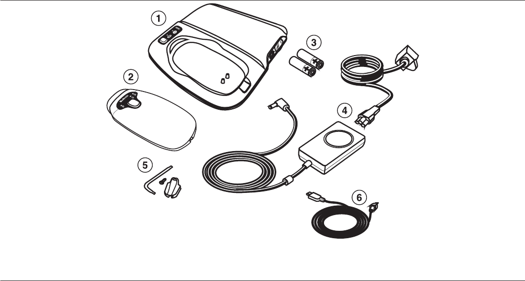
The package contains:
• 24970A Base
• ME20A054F03 power supply (Medtronic re-order number: 249701), 1.8 m (approximately 6 ft)
• 249705 AC power cord, 1.8 m (approximately 6 ft)
• AA alkaline batteries, quantity of 2
• 24967 Patient Connector
• 249702 USB cable, approximately 3 m (10 ft)
• 249672 Tether Kit
• Literature
2.2 System components
Figure 1. Base components
1 Base
2 Patient connector
3 Batteries
4 Power supply and power cord
5 Tether kit
6 USB cable
12
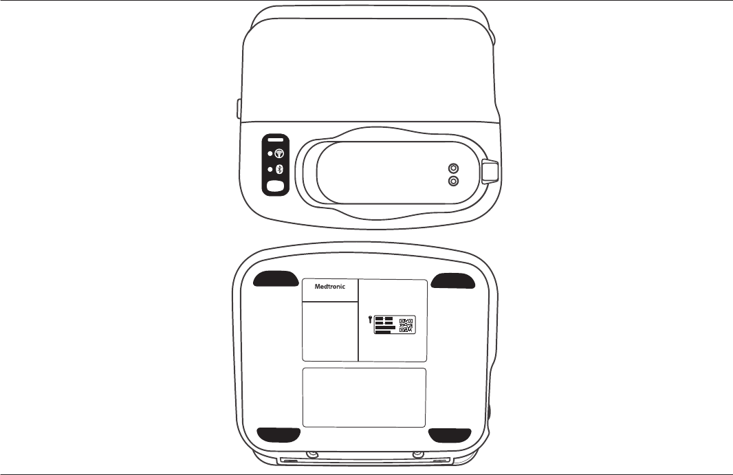
Figure 2. Base top and bottom view
Base – Encloses the Analyzer hardware that connects to a patient’s implantable device cardiac lead system to assess its electrical
performance. The base provides the communication link between the Analyzer hardware and the app for lead analysis. The base
contains a radio-frequency (RF) transmitter and receiver.
Mobile device (not included) – When running the Medtronic app and paired with the base, provides the user interface to assess the
electrical performance and placement of implantable cardiac device lead systems.
Patient connector – Can be charged by placing it on the base charge cradle or by connecting the USB cable to both the base and
the patient connection ports.
For more information about the 24967 patient connector, refer to its instructions for use.
AA Alkaline batteries – Power the Analyzer hardware within the base.
Power supply and power cord – Connects to an AC power outlet to power the base.
Tether kit – Semi-permanently connects the USB cable to the patient connector. Contains a Torx wrench, screw, and cable retainer.
USB cable – Plugs into the base and patient connector to charge the patient connector. You can charge the patient connector either
by placing it in the base charge cradle or by connecting the USB cable. In “noisy” environments where electrical interference causes
Bluetooth communication issues, connecting the USB cable to the base and the patient connector can improve patient connector
connectivity and performance.
Warning: Use the Medtronic-supplied USB cable with the 24970A base and 24967 patient connector only.
Warning: Do not modify this equipment. Modifications may reduce system effectiveness and impact user or patient safety. Modifying
the device without the approval of Medtronic could void the user’s authority to operate the equipment.
13
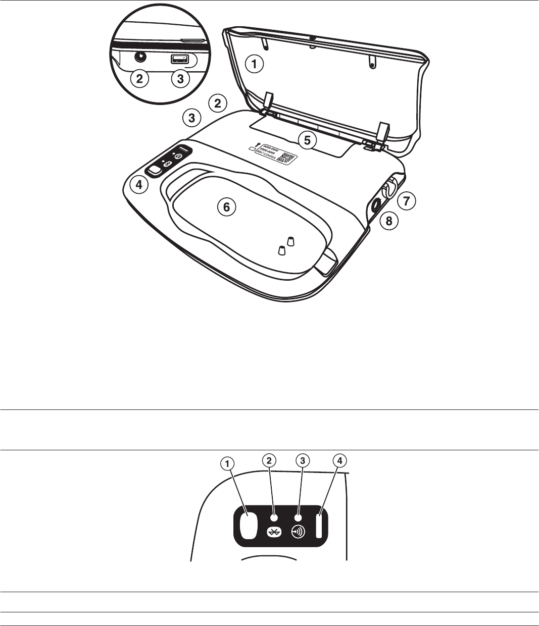
2.2.1 Features and connection ports
Figure 3. Base features and connection ports
1 Lid and mobile device support
2 Power connection port
3 USB connection port, for use only with the 24967 patient connector and Medtronic-supplied USB cable
4 Indicator lights and status panel
5 Battery access door
6 Patient connector charge cradle
7 Type CF patient or surgical cable connection port and Analyzer green indicator light
8 Type BF ECG cable connection port
2.2.2 Indicator lights
Figure 4. Base indicator lights
1 Button
2 Bluetooth connection status
3 Telemetry status
4 Power indicator
Table 1. Base icons and indicator lights
Icon Indicator Color Description
N/A Button Gray Powers on the Bluetooth wire-
less technology in the base if it
has automatically powered off.
14

Table 1. Base icons and indicator lights (continued)
Icon Indicator Color Description
When you tap Flash in the app
to identify the base, all of the
base indicator lights flash.
Press the button on the base to
verify the identification and turn
the lights off.
Bluetooth connection status Blue When flashing, it indicates that
the base is broadcasting its sta-
tus or is being paired with the
mobile device. When steadily
lit, it indicates that the base is
paired and communicating with
the mobile device. When off, it
indicates that Bluetooth in the
base has been powered off.
If the base has not been paired
with the app, the base automat-
ically powers down Bluetooth
after an extended period of time
(default of 180 minutes). Press
the button on the base to power
Bluetooth back on to pair it with
the app.
Telemetry status Green When lit, it indicates that the
base is communicating with an
implantable device.
N/A Power indicator Green When lit, indicates that the base
is powered on.
Note: Additional connection and status indicators are present at the top of the app screen to help you determine connection status
or identify issues. For more information, refer to the help within the app.
2.3 Compatible accessories
The following compatible accessories are available for the base:
• ME20A0540F03 power supply (Medtronic re-order number: 249701), 1.8 m (approximately 6 ft)
• 249705 AC power cord, 1.8 m (approximately 6 ft)
• 249702 USB cable, approximately 3 m (10 ft)
• 249672 Tether Kit
• 249703 Wall mount: mounts the base to the wall when table space is a concern
• 24967 Patient Connector
The following compatible cables and adaptors are available for the base. Surgical and patient cables connect the base to cardiac
leads for lead analysis. Adaptors allow surgical and patient cables to be connected to the base when their plugs are not compatible
with the Type CF connection port on the base. Ground cables connect to the base and complete the electrical circuit when connected
to unipolar implantable cardiac device leads.
• 2292 Surgical cable, 3.66 m (12 ft)
• 5103 A/V adaptor
• 5114 Adaptor
• 5832 Surgical cable, approximately 3.5 m (12 ft)
• 5833S Surgical cable, 1.83 m (6 ft)
• 5833SL Surgical cable, 3.66 m (12 ft)
• 5473 Ground cable
• 5436 Analyzer patient cable, 3.66 m (12 ft)
The following compatible ECG interface cables, ECG cables, EKG leads, and adaptors are available for the base. ECG interface
cables connect the base to ECG monitors for the display of live waveforms. ECG cables and leads connect the base to surface
electrodes on the patient for the display of live waveforms. Adaptors allow ECG monitors with phono connectors to be connected to
the base.
15
• 5437 ECG Interface cable, 6.4 m (20 ft)
• 5437A Adaptor
• 2090EC ECG cable, approximately 2.6 m (103 in)
• 2090ECL ECG cable, approximately 5.5 m (215 in)
• 9790LA ECG leads, approximately 1 m (40 in)
• 9790XLA ECG leads, approximately 1 m (40 in)
Contact your local Medtronic representative to order them.
Warning: Use the Medtronic-supplied components only. Use of unapproved components may reduce device effectiveness or impact
user or patient safety.
2.4 Setup
This section describes how to:
• Install or replace the batteries that power the Analyzer hardware in the base
• Power on the base
• Download the app
2.4.1 Installing or replacing the Analyzer batteries
The Analyzer hardware inside the base is powered by 2 AA Alkaline or Lithium-ion batteries. Replace the batteries every 2 years or
when prompted by the app.
Cautions:
• Use only standard, non-rechargeable Alkaline or Lithium-ion AA batteries in the base. The Analyzer hardware is not designed to
work with rechargeable batteries.
• Do not replace the battery while the base is connected to a patient or during an Analyzer session. The battery connects to circuitry
which connects directly to the patient and could provide a low-resistance path to the myocardium for electrostatic discharge (ESD)
or leakage currents.
• Do not simultaneously touch the patient and any metal parts of the base (such as the USB connection port or patient connector
charging contacts) as voltage may be present. Application of voltage to the patient may impact user or patient safety.
1. End the Analyzer session and disconnect the base from the patient, if needed.
16

2. Unplug the cord from the power supply from the base, if needed.
3. Use a #1 Phillips head screwdriver (not included) to loosen and remove the two screws from the bottom of the base near the
hinge.
4. Lift the lid on top of the base.
5. Insert a coin or flathead screwdriver (not included) into the slot next to the battery access door and lift to open the door. Slide the
door backwards and lift it away.
The seal prevents liquids from entering the battery compartment; you may need to pry open the door.
17

6. Remove the depleted batteries from the battery compartment, if needed.
Safely discard the depleted batteries according to your organization’s policies and local environmental requirements.
7. Install 2 new non-rechargeable AA Alkaline or Lithium-ion batteries in the battery compartment.
Refer to the diagram in the battery compartment to install the batteries in the correct orientation for their polarity.
8. Push down the battery access door to close it.
9. Reinstall the two screws on the bottom of the base and tighten them to secure and seal the battery access door.
10. Plug the cord from the power supply back into the base to power it on.
2.4.2 Powering on the base
Connect the power supply to the base and to an AC power outlet (AC mains) to power on the base.
Warning: Use only the Medtronic-supplied power supply to power the base.
18
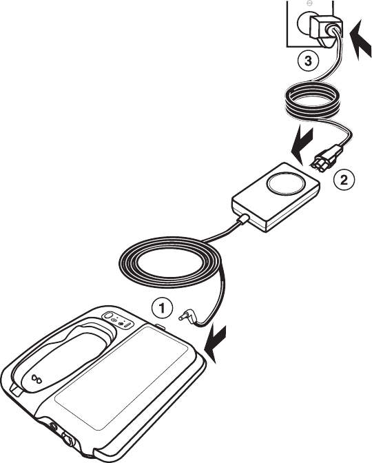
1. Plug the cord from the power supply into the base.
2. Plug one end of the power cord into the power supply.
3. Plug the other end of the power cord into the AC power outlet.
Notes:
• The base, power supply, and power cord form a medical electrical system when connected.
• If you need to disconnect the base from the AC power mains, the power cord is the power disconnect at the mains outlet.
• Position the base so that it can be easily disconnected or unplugged from the wall.
• The third conductor in the power cord plug, if present, is a functional earth connection.
2.4.3 Downloading the app
1. Make sure the mobile device is connected to the Internet.
2. Navigate to the app store and locate the CareLink SmartSync Device Manager app.
3. Tap the app icon to download the app onto the mobile device.
4. Install the app.
5. Tap the app icon on the mobile device desktop to open it.
6. Follow the instructions in the app to complete the installation and register the app.
During the registration process, the app prompts you to enter the security key on the base. The security key is printed in these
locations on the base:
• Under the lid
• On the label on the bottom of the base
You can also tap SCAN QR CODE to open a QR code scanner to scan the base’s security code. Position the QR code on the
base within the scanner outline to automatically scan and enter it.
2.5 Connecting the base to the app
When you completed the app installation and registration process, you connected the base to the app. The app automatically detects
and connects to this base when it is powered on and within range of the mobile device. If the connection between the base and the
app is lost, the base and app automatically attempt to reestablish communication. In certain situations when the connection is lost,
the app may prompt you to press the button on the base to identify it.
19

You can connect multiple different bases to the app, but only one base can be connected to and communicating with the app at the
same time. You can also disconnect a base from the app in order to connect to a different one. However, you cannot switch between
bases during an Analyzer session.
During connection, the base and the app exchange messages to establish the connection. If the base does not receive a confirmation
message from the app within 5 minutes after starting the connection process, the base automatically discontinues the process and
disconnects its Bluetooth connection. You can restart the connection process from the app, if needed.
If the base has not been connected to an app for an extended period of time (default of 180 minutes), it automatically powers down
its Bluetooth connection. When Bluetooth in the base is powered down, the blue Bluetooth LED indicator on the base turns off. To
power up the base’s Bluetooth connection, press the button on the base or start the connection process from the app.
2.5.1 Reconnecting to the app
The app saves the connection information about the base it is currently connected to even if that connection is not active (for example,
if the base is powered off, out of range, or Bluetooth is not enabled on the mobile device). You can reconnect the base to the app quickly
without re-entering the security code.
1. Verify that the base is powered on and the app is running and active on the mobile device.
2. If needed, press the button on the base to power on its Bluetooth connection.
3. If the app does not automatically reconnect, do the following:
a. Tap SELECT BASE on the app screen.
The Select an accessory dialog box opens.
b. Verify the serial number of the previously paired base, then tap that base in the list.
4. To verify the connection, tap FLASH.
Caution: Verify that the app is connected to the correct base. Connecting to a different base may result in confusion during an
Analyzer session or delay a procedure.
The lights on the base flash, indicating that it is connected to the app. Press the button on the base to turn the lights off. You can
also view connection status in the status indicators at the top of the app screen. The base is connected to the app and ready to
use.
2.5.2 Connecting a new base to the app
You can connect a new base to the app when needed. When you connect a new base to the app, you enter the base’s security key
to ensure that communications are transmitted securely.
Caution: After connecting a new base to the app, verify that the correct base is connected. Connecting to a different base may result
in confusion during an Analyzer session or delay a procedure.
You cannot connect to a new base during an Analyzer session.
1. If needed, tap DISCONNECT on the app screen to disconnect the currently connected base from the app.
2. Verify the following:
• The new base is powered on.
• The new base is not currently connected to a CareLink SmartSync Device Manager app running on a different mobile device.
• The app is running and active on the mobile device you want to connect to the new base.
20
3. If needed, press the button on the base to power on its Bluetooth connection.
The app automatically detects the base when it is powered on and within range.
4. On the app home screen, tap SELECT NEW or SELECT NEW BASE.
The Select an accessory dialog box opens.
5. Tap the base in the list that you want to connect to.
6. Use one of the following methods to enter the base security key.
• Type in the security key and tap ENTER.
• Tap SCAN QR to scan the security key. The app opens a QR code scanner; position the QR code on the base within the
scanner outline to automatically enter it.
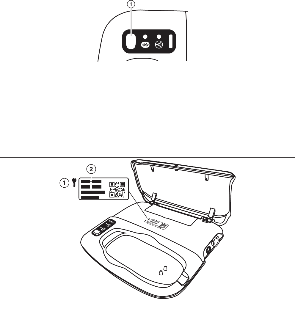
You can find the security key printed in these locations on the base:
• Under the lid.
• On the label on the bottom of the base.
Figure 5. Patient Connector security key
1 Security key symbol
2 Security key code
7. If you are prompted by the mobile device to accept a Bluetooth Pairing Request, confirm that the serial number in the request
matches the serial number on the base.
• Decline the request if the serial number does not match the serial number on the base.
• Accept the request to connect the base to the app.
8. To verify the connection, tap FLASH.
Caution: Verify that the correct base is connected to the app. Connecting to a different base may result in confusion during an
Analyzer session or delay a procedure.
The lights on the base flash, indicating that it is connected to the app. Press the button on the base to turn the lights off.You can
also view connection status in the status indicators at the top of the app screen. The base is connected to the app and ready to
use.
21
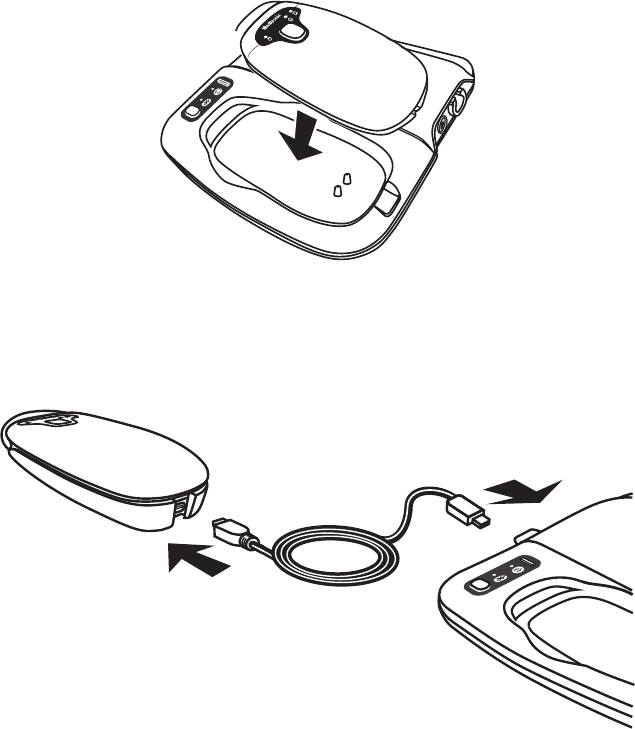
2.6 Charging the patient connector battery
Caution: Charge the patient connector before use. If the patient connector is not adequately charged before beginning a procedure,
you may not be able to complete that procedure.
You can charge the patient connector in one of the following ways:
• Through the charge cradle on the base.
• Through the USB cable.
A separate power supply, MENB1020A0500XXX (Medtronic reorder number: 249651) is also available to charge the patient
connector. Contact your Medtronic representative for details. For more information, refer to the 24967 patient connector instructions
for use.
2.6.1 Charging using the base charge cradle
Place the patient connector on the base charge cradle to charge the patient connector. The magnet under the charge cradle secures
the patient connector and ensures charging.
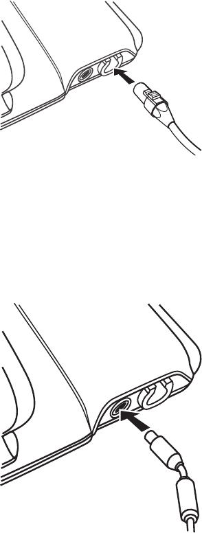
2.6.2 Charging using the USB cable
Plug the USB cable into the connection ports on both the patient connector and the base to charge the patient connector via USB.
Electrical interference from other equipment can cause issues with Bluetooth communication between the patient connector and the
app. Plugging the USB cable into the patient connector and the base can improve patient connector connectivity and performance in
these “noisy” environments.
1. Open the cover located on the bottom edge of the patient connector.
2. Plug the mini-B connector of the USB cable into the patient connector.
3. Plug the type-A connector of the USB cable into the USB port on the side of the base.
Warnings:
• Use only the Medtronic-supplied USB cable with the patient connector and base. Use of an unapproved cable may damage
equipment or impact user or patient safety.
• Use the USB port on the base and the Medtronic-supplied USB cable with the 24970A base and 24967 patient connector only.
The USB connectivity on the base is not compatible with other equipment (such a mobile device or USB “thumb” drive).
2.6.3 Attaching the tether kit
The tether kit provides a way to semi-permanently attach the USB cable to the patient connector. This is an optional configuration.
1. Locate the power supply connector cover on the bottom of the patient connector.
22

2. Use the Medtronic-supplied wrench to remove the screw.
3. Remove the cover from the patient connector.
4. Plug the mini-B connector of the USB cable into the patient connector.
5. Slide the cable retainer over the USB cable connector.
6. Insert the screw into the bottom of the cable retainer and tighten the screw using the Medtronic-supplied wrench.
Caution: Do not over tighten the screw when attaching the tether kit.
Warning: Use the Medtronic-supplied components only. Use of unapproved components may reduce patient connector
effectiveness or impact user or patient safety.
2.7 Troubleshooting potential interference
Interference from other electronic equipment can result in reduced quality of service and loss of communication between the base and
the app. To address possible interference caused by other electronic equipment, take one or more of the following measures:
• Reorient or relocate the electronic equipment.
• Move the electronic equipment further away from the base and the mobile device.
• Connect the electronic equipment to an outlet on a different circuit.
• Move the base and mobile device closer together. For best results, place the base no further than 2 m (approximately 6 ft) from
the mobile device to remain in range for Bluetooth communication.
• Consult Medtronic for help.
23
3 Conducting an Analyzer session
3.1 Conducting an Analyzer session
Use the Analyzer hardware in the base and the Analyzer tools in the app to assess the correct placement and the electrical
performance of implantable cardiac device leads. To perform this assessment, you start an Analyzer session and connect the base
to the cardiac device lead system.
Warnings:
• Backup pacing and defibrillation should be readily available during procedures.
• Ensure proper atrial or ventricular lead connections are made to the patient or surgical cables. For more information on connecting
patient or surgical cables to leads, refer to the instructions for use for that patient or surgical cable.
Caution: The Analyzer provides pacing support during execution of tests. For pacing dependent patients, ensure the settings provide
appropriate pacing before starting the test.
1. Verify the base is powered on and connected to the app, and the app is running and active on the mobile device.
2. In the app, tap START SESSION if necessary to return to the home screen.
3. Tap LAUNCH ANALYZER.
The Analyzer runs a check to verify the charge level of the battery in the base. A message is displayed in the app if the batteries
need to be replaced.
4. Connect the patient or surgical cable to the base.
a. Orient the cable plug so that the latch faces upward.
b. Insert the cable plug into the Type CF patient or surgical cable port on the side of the base until it “clicks.”
c. Gently pull on the cable plug after inserting it to ensure that the connection is secure.
d. Connect the other end of the cable to the cardiac device leads.
For more information on connecting the cable to the cardiac device leads, refer to the instructions for use for that cable. For
more information on connecting cables to the Model 5103 or Model 5104 adaptors, refer to the instructions for use for that
adaptor.
5. Connect the ECG cable to the base.
a. Orient the cable plug so that the red dot or arrow faces upward.
b. Insert the cable plug into the Type BF ECG cable connection port on the side of the base.
c. Connect the other end of the cable to skin electrodes on the patient or to the ECG monitor.
For more information on connecting the cable to the skin electrodes or ECG monitor, refer to the instructions for use for that
cable. For more information on connecting cables to the Model 5437A adaptor, refer to the instructions for use for that
adaptor.
24
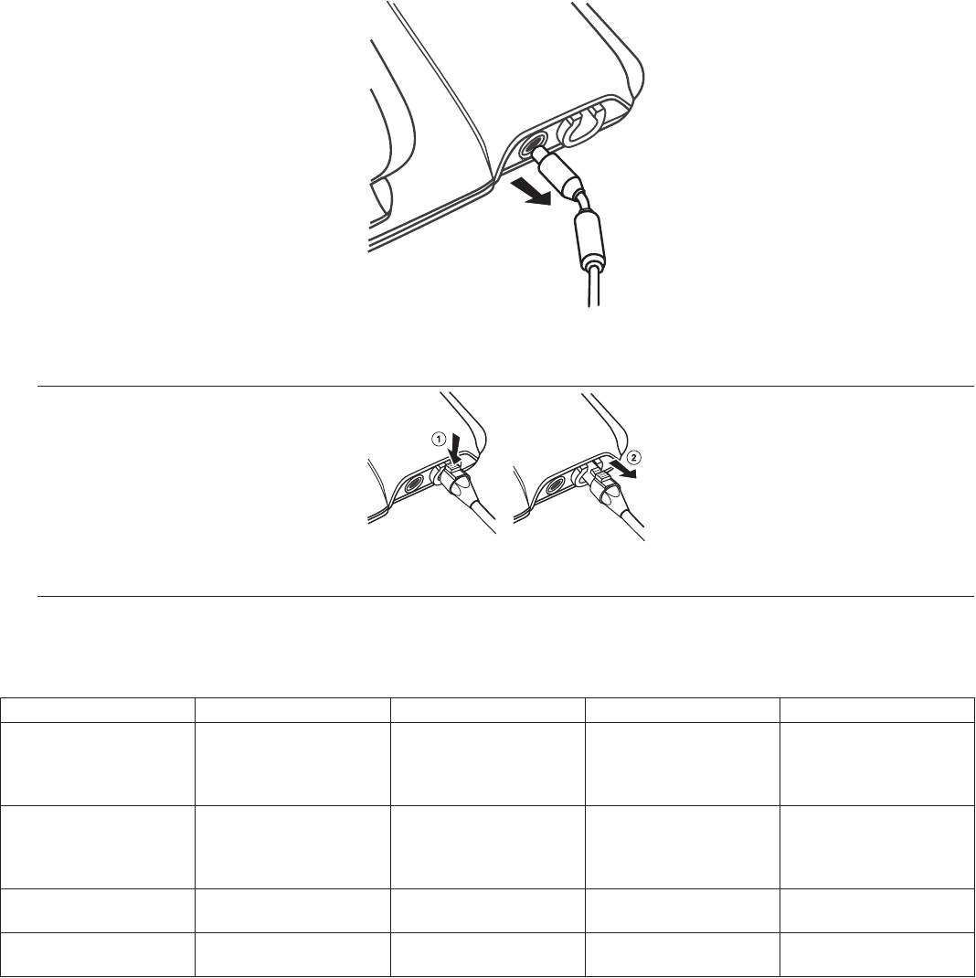
6. In the app, use the tools on the ANALYZER menu to conduct the session.
For more information on these tools, refer to the Analyzer help. Tap an Analyzer tool in the menu to open its screen, then tap HELP
and select a topic from the list.
7. As you work, generate any reports needed for documentation. Tap SAVED REPORTS in the app menu to view and export PDF
report files.
8. When you finish, tap END SESSION to end the Analyzer session. When prompted, tap END NOW to return to the app home
screen.
9. Disconnect the ECG cable from the skin electrodes on the patient or from the ECG monitor.
10. Disconnect the ECG cable from the base by pulling the plug from the connection port.
11. Disconnect the patient or surgical cable from the cardiac device leads.
12. Disconnect the patient or surgical cable from the base.
Figure 6. Disconnecting the patient or surgical cable
1 Press down on the latch button on the cable plug.
2 Pull the cable plug straight out of the connection port on the base.
3.1.1 Measurement parameters
All measurements and accuracies assume a noise-free environment.
Table 2. Measurement parameter values
Parameter Range Resolution Accuracy Notes
P-Wave amplitude 0.125−25 mV 0.125 mV ±20% Amplitude measurement
specifications are based
on a 40 ms sine2 input
signal.
R-Wave amplitude 0.125−25 mV 0.125 mV ±20% Amplitude measurement
specifications are based
on a 40 ms sine2 input
signal.
Impedance (Atrial) 0; 19…3000 Ω 19 Ω -20/+60 Impedance range based
on a 5 V output setting.
Impedance (Ventricular) 0; 19…3000 Ω 19 Ω -20/+60 Impedance range based
on a 5 V output setting.
3.2 Delivering emergency VVI pacing
The CareLink SmartSync Device Manager can deliver VVI pacing when needed in emergency situations. To do so, tap the
Emergency button at the top of the app screen.
25

Warning: During a loss of communication in the system, emergency VVI pacing cannot be delivered. Use external pacing support or
defibrillation equipment to provide appropriate therapy to the patient.
Caution: The Emergency button is not available during tests, such as Rapid Atrial Stimulation and Pulse Width/Amplitude tests. End
the test to enable the Emergency button again. Ending the test returns parameters to permanent values, which may eliminate the
need for emergency VVI pacing.
For more information the Emergency button and emergency VVI pacing parameters, refer to the Analyzer help in the app. Tap an
Analyzer tool in the menu to open its screen, then tap Help and select a topic from the list.
3.3 Troubleshooting
An error or an informational message is displayed in the app if there is a problem with the base. For more information about specific
messages, refer to the app help. For some conditions, contact Medtronic.
3.3.1 Analyzer hardware battery status
When you launch the Analyzer in the app, the Analyzer runs a check on the status of the batteries powering the hardware in the base.
Messages are displayed on the app screen when battery status changes.
Condition Action Result
The REPLACE BATTERIES message is
displayed on the app screen. The mes-
sage indicates that the batteries are too
low for safe operation and must be
replaced.
The batteries are depleted and do not have
enough charge to continue safely power-
ing the hardware. Tap EXIT to close the
message in the app and replace the bat-
teries before starting the next Analyzer
session.
The batteries have been replaced and the
battery status check passes.
The REPLACE BATTERIES message is
displayed on the app screen. The mes-
sage indicates that the batteries are old.
The batteries are more than 2 years old but
have enough charge to continue powering
the hardware. The batteries should be
replaced to ensure continued safe opera-
tion.
You can replace the batteries now before
continuing with the Analyzer session, or
you can complete the current session and
replace the batteries later.
Tap CANCEL to close the message and
replace the batteries now, or tap CON-
TINUE to close the message and replace
the batteries at the next available opportu-
nity.
The message continues to be displayed
each time you launch the Analyzer until the
batteries have been replaced or are deple-
ted. After you replace the batteries, the
battery status check passes and the mes-
sage closes permanently.
3.3.2 Loss of Bluetooth connection
The base uses a Bluetooth connection to pair with the app installed on the mobile device to send data. The Bluetooth light on the base
indicates the status of the Bluetooth connection between the base and the app.
Condition Action Result
The blue indicator light flashes. Check that Bluetooth is enabled on the
mobile device. Enable Bluetooth on the
mobile device if it is not enabled.
Move the mobile device closer to the base
and confirm that the blue indicator light on
the base turns back on. For best results,
place the base no further than 2 m (approx-
imately 6 ft) from the mobile device to
remain in range for Bluetooth communica-
tion.
Check that nothing is physically blocking
the signal between the base and the
mobile device.
The blue indicator light is on. When the
blue indicator light is on, the Bluetooth con-
nection between the base and the mobile
device is reestablished.
3.3.3 Loss of communication with the app
During an Analyzer session, the light next to the Type CF applied part connection port on the base flashes if communication with the
app on the mobile device has been lost.
26

Condition Action Result
The green indicator light flashes and the
LOSS OF COMMUNICATION message is
displayed on the app screen. Communica-
tion with the app has been lost.
When communication is lost, the Analyzer
discontinues any in-progress tests and
returns to programmed pacing values. The
flashing light indicates that the Analyzer is
operating at previously programmed pac-
ing values.
The Analyzer continues to operate for a
length of time after communication is lost.
If the surgical or patient cables are con-
nected to implantable device leads, the
Analyzer continues to operate for 60
minutes. If the surgical or patient cables
are not connected to leads, the Analyzer
continues to operate for 5 minutes.
Verify that the base is powered on and
Bluetooth is enabled on the mobile device.
Enable Bluetooth on the mobile device if it
is not enabled.
Move the mobile device closer to the base
to improve connectivity. For best results,
place the mobile device no further than 2 m
(approximately 6 ft) from the app to remain
in range for Bluetooth communication.
Check that nothing is physically blocking
the signal between the base and the
mobile device.
Tap CLOSE to close the message on the
app screen and return to the Analyzer test
screen.
The green indicator light stops flashing and
turns off. Communication between the
base and the app has been restored.
4 Maintaining the 24970A base
4.1 Cleaning the 24970A base
4.1.1 Cautions and notes for cleaning
Cautions:
• Clean the base as needed per your organization’s policies. Use only the recommended methods to clean the base if soil
accumulation is visible.
• Use only recommended cleaners on the base. Using other cleaners, solvents, or disinfectants (such as bleach, ethers, acetone,
or chlorinated solvants) may damage the base plastic, circuitry, or metal components.
• Do not immerse the base in water or cleaning agents. Do not use automated machine washers. Severe damage to the base may
occur.
• Do not sterilize the base by ethylene oxide, gamma radiation or steam-sterilization (autoclave). Severe damage to the device,
housing, or labels may occur using these methods.
Notes:
• While cleaning the base, visually inspect its case, connection ports, power cord, and USB cable for damage. Contact your
Medtronic representative if any components are damaged.
• The base is designed to withstand normal cleaning over its product life.
27

4.1.2 Cleaning the base
1. Disconnect the power cord from the power port on the side of the base.
2. Clean the base thoroughly using a 70% isopropyl alcohol prep pad or a sterile gauze pad or sponge dampened with 70%
isopropyl alcohol.
3. Wipe all external surfaces of the base to remove all visible soil.
a. Wipe the top of the base, including the charge cradle and its contacts.
28

b. Lift the base lid and wipe the bottom of the lid, the hinge channel area, the tablet support notch, and the area underneath the
lid.
c. Wipe the bottom of the base.
d. Wipe the channel and base sides. Wipe only the exterior surfaces of the recessed connection ports; cleaning inside the port
may damage it.
4. Allow to air dry approximately 5 minutes or until dry.
4.1.3 Additional resources
For additional information about cleaning the base, contact Medtronic Instruments Technical Services:
• Phone: +1 800 638 1991
• Email: tshelp@Medtronic.com
For more information and resources on cleaning and disinfecting medical devices, visit the CDC and HICPAC websites.
29

4.2 Specifications
Table 3. Base specifications
Standards (The base complies with the following:)
Radio frequency wireless specifications and applicable standards
EMC EN / IEC 60601-1-2
EN 300 328
EN 301 489
EN 302 195
EN 301 839
EN 55011 Class A
Radio FCC CFR 47
Patient safety UL/CUL 60601-1, Type BF applied part, Type CF applied parta
EN 60601-1, Class 2, continuous operation, Type BF, Type CFa
AC power requirement
Voltage 100–240 VAC nominal
Frequency 50/60 Hz nominal
Battery
Type AA Alkaline (LR6) or Lithium-ion, non rechargeable (quantity of 2)
Voltage 1.5 V each
Base electrical specifications
Power supply
Model ME20A0540F03 power supply (Medtronic re-order number 249701)
Voltage in 100-240 VAC 0.5A at 50-60 Hz
Voltage out 5 VDC 3 A
USB cable
Model 249702 USB cable
Voltage 5 V 0.8 A
Power 4 W
Charge cradle
Model 24970A
Voltage 5 V 0.8 A
Power 4 W
IEC 60529 Degrees of Protection Provided by Enclosures (IP Code)
Ingress This product complies with international electrical safety rating IP2X with regard to
ingress of dust, other foreign objects, and water as required by IEC 60601-1.
Physical dimension and weight
Height
Width
Depth
Weight
4.6 cm (1.8 in)
24 cm (9.5 in)
20.8 cm (8.2 in)
0.91 kg (2.0 lbs)
Temperature limits
Operating
Storage
Transport
10°C to 35°C (50°F to 95°F)
15°C to 30°C (59°F to 86°F)
- 30°C to 55°C (-22°F to 131°F)
Humidity limits
Operating
Storage
Transport
8%-80%
15%-93% at 35°C (95°F)
15%-93% at 35°C (95°F)
Altitude
Maximum 3000 m
Connectivity
Conexus wireless telemetry
Frequency range 402-405 MHz
Modulation frequency Frequency shift key
Output power 25 µW EIRP max
30

Table 3. Base specifications (continued)
Bluetooth 2.1 and 4.0
Frequency range 2.4-2.483 GHz
Modulation frequency Gaussian frequency shift key
Output power Less than 10 mW EIRP
aThe ECG cable (Type BF), 24967 Patient Connector (Type BF) and patient or surgical cable (Type CF) are the only accessories that come into direct
contact with the patient. The base itself is not intended to come into contact with the patient during normal use.
4.2.1 Expected service life
The base has an expected service life of 5 years.
4.2.2 Disposal of the base
Return the base to Medtronic for proper disposal. Contact Medtronic at the address or telephone number on the back cover for
information on returning the base.
5 Electromagnetic compatibility declaration
The following list of accessories are compliant with the requirements of IEC 60601-1-2.
Accessory Maximum length
ME20A0540F03 Power supply
(Medtronic re-order number: 249701)
1.8 m (6 ft)
249705 AC power cord 1.8 m (6 ft)
249702 USB cable 3 m (10 ft)
24967 Patient Connector N/A
2292 Surgical cable 3.66 m (12 ft)
5832 Surgical cable 3.5 m (12 ft)
5833S Surgical cable 1.83 m (6 ft)
5833SL Surgical cable 3.66 m (12 ft)
5346 Analyzer patient cable 3.66 m (12 ft)
5437 ECG Interface cable 6.4 m (20 ft)
2090EC EKG cable 2.6 m (103 in)
2090ECL EKG cable 5.5 m (215 in)
9790LA EKG leads 1 m (40 in)
9790XLA EKG leads 1 m (40 in)
Use of accessories other than what is specifically listed may result in increased emissions or decreased immunity of the 24970A base.
The 24970A base needs special precautions regarding electromagnetic compatibility (EMC) and needs to be installed and used
according to the EMC information provided in the accompanying documents.
The 24970A base should not be used adjacent to or stacked with other equipment that is not part of the device manager system (base,
mobile device, and accompanying accessories). If adjacent or stacked use is necessary, the 24970A base should be observed to
verify normal operation in the configuration in which it will be used.
The 24970A base contains RF transmission and receiving capabilities. Consequently, it is possible that other equipment may interfere
with the 24970A base even if that other equipment complies with CISPR emission requirements. The following is a technical summary
of the RF communication properties:
Transmitting and receiving:
• Technology type: Conexus wireless telemetry, Bluetooth wireless technology
• Frequency of operation: 402 MHz to 405 MHz, 2.4 GHz to 2.483 GHz
• Modulation characteristics: Frequency shift key, Gaussian frequency shift key
• Field strength: 25 µW EIRP max, less than 10 mW EIRP
31

Guidance and manufacturer’s declaration—electromagnetic emissions
The 24970A base is intended for use in the electromagnetic environment specified below. The customer or the user of the 24970A
base should assure that it is used in such an environment.
Emissions test Compliance Electromagnetic environment—guidance
RF emissions
CISPR 11
Group 1 The 24970A base uses RF energy only for its internal function. There-
fore, its RF emissions are very low and are not likely to cause any inter-
ference in nearby electronic equipment.
RF emissions
CISPR 11
Class A
Harmonic emissions
IEC 61000-3-2
Class A The 24970A base is suitable for use in all establishments other than
doemstic, and may be used in doemstic establishments and those
directly connected to the public low-voltage power supply network that
supplied buildings used for domestic purposes, provided the following
warning is heeded:
Warning: This equipment/system is intended for use by healthcare
provessionals only. This equipment/system may cause radio interfer-
ence or may disrupt the operation of nearby equipment. It may be nec-
essary to take mitigation measures, such as re-orienting or relocating
the 24970A base or shielding the location.
Voltage fluctuations/flicker emissions
IEC 61000-3-3
Complies
Guidance and manufacturer’s declaration—electromagnetic immunity
The 24970A base is intended for use in the electromagnetic environment specified below. The customer or the user of the 24970A
base should assure that it is used in such an environment.
Immunity test IEC 60601 Test level Compliance level Electromagnetic environment—guid-
ance
Electrostatic discharge (ESD) ±6 kV contact ±8 kV contact Floors should be wood, concrete, or
ceramic tile. If floors are covered with syn-
thetic material, the relative humidity should
be at least 30%.
IEC 61000-4-2 ±8 kV air ±15 kV air
Electrical fast transient/burst ±2 kV for power supply
lines
±2 kV for power supply
lines
Mains power quality should be that of a typ-
ical commercial or hospital environment.
IEC 61000-4-4 ±1 kV for input/ output
lines
±1 kV for input/ output
lines
Surge ±1 kV differential
mode
±1 kV differential
mode
IEC 61000-4-5 ±2 kV common mode ±2 kV common mode
Voltage dips, short interruptions, and
voltage variations on power supply
input lines
IEC 61000-4-11
<5% UT
(>95% dip in UT)
for 0.5 cycle
<5% UT
(>95% dip in UT)
for 0.5 cycle
Mains power quality should be that of a typ-
ical commercial or hospital environment. If
the user of the 24970A base requires con-
tinued operation during power mains inter-
ruptions, it is recommended that the
24970A base be powered from an uninter-
ruptible power supply or a battery.
Note:UT is the AC mains voltage prior to
application of the test level.
40% UT
(60% dip in UT)
for 5 cycles
40% UT
(60% dip in UT)
for 5 cycles
70% UT
(30% dip in UT)
for 25 cycles
70% UT
(30% dip in UT)
for 25 cycles
<5% UT
(>95% dip in UT)
for 5 s
<5% UT
(>95% dip in UT)
for 5 s
Power frequency (50/60 Hz) mag-
netic field
3 A/m 30 A/m Power frequency magnetic fields should be
at levels characteristic of a typical location in
a typical commercial or hospital environ-
ment.
IEC 61000-4-8
32
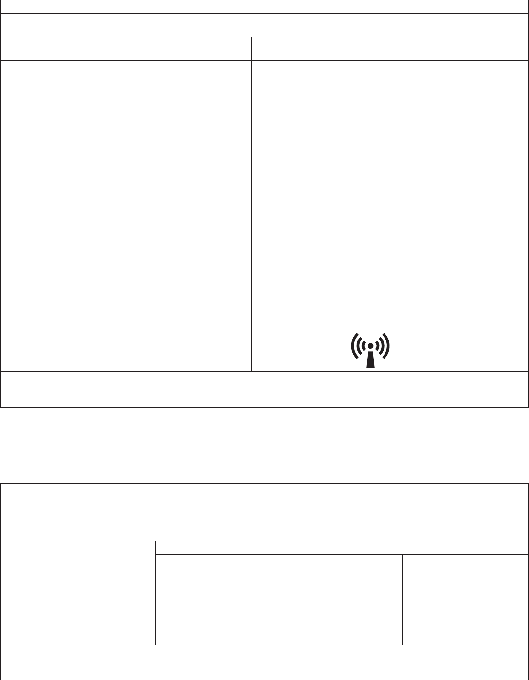
Guidance and manufacturer’s declaration—electromagnetic immunity
The 24970A base is intended for use in the electromagnetic environment specified below. The customer or the user of the 24970A
base should assure that it is used in such an environment.
Immunity test IEC 60601 Test level Compliance level Electromagnetic environment—guid-
ance
Portable and mobile RF communications
equipment should be used no closer to any
part of the 24970A base, including cables,
than the recommended separation distance
calculated from the equation applicable to
the frequency of the transmitter.
Recommended separation distance
Conducted RF 3 VRMS (volts root-
meansquare)
10 V d = 0.35√P
IEC 61000-4-6 150 kHz to 80 MHz
Radiated RF 3 V/m 10 V/m d = 0.35√P for 80 MHz to 800 MHz
IEC 61000-4-3 80 MHz to 2.5 GHz d = 0.70√P for 800 MHz to 2.5 GHz
where P is the maximum output power rat-
ing of the transmitter in watts (W) according
to the transmitter manufacturer and d is the
recommended separation distance in
meters (m).
Field strengths from fixed RF transmitters,
as determined by an electromagnetic site
survey,a should be less than the compliance
level in each frequency range.b
Interference may occur in the vicinity of
equipment marked with the following sym-
bol:
Note 1: At 80 MHz and 800 MHz, the higher frequency range applies.
Note 2: These guidelines may not apply in all situations. Electromagnetic propagation is affected by absorption and reflection from
structures, objects, and people.
aField strengths from fixed transmitters, such as base stations for radio (cellular/cordless) telephones and land mobile radios, amateur radio, AM
and FM radio broadcast, and TV broadcast cannot be predicted theoretically with accuracy. To assess the electromagnetic environment due to
fixed RF transmitters, consider an electromagnetic site survey. If the measured field strength in the location in which the 24970A base is used
exceeds the applicable RF compliance level above, observe the 24970A base to verify normal operation. If abnormal performance is observed,
additional measures may be necessary, such as re-orienting or relocating the 24970A base.
bOver the frequency range of 150 kHz to 80 MHz, field strengths should be less than 10 V/m.
Recommended separation distances between portable and mobile RF communications equipment and the 24970A base
The 24970A base is intended for use in an electromagnetic environment in which radiated RF disturbances are controlled. The
customer or the user of the 24970A base can help prevent electromagnetic interference by maintaining a minimum distance between
portable and mobile RF communications equipment (transmitters) and the 24970A base as recommended below, according to the
maximum output power of the communications equipment.
Rated maximum output power of
transmitter
Separation distance according to frequency of transmitter
150 kHz to 80 MHz 80 MHz to 800 MHz 800 MHz to 2.5 GHz
d = 0.35√P d = 0.35√P d = 0.70√P
0.01 W 0.035 m 0.035 m 0.070 m
0.1 W 0.11 m 0.11 m 0.22 m
1 W 0.35 m 0.35 m 0.70 m
10 W 1.1 m 1.1 m 2.0 m
100 W 3.5 m 3.5 m 7.0 m
For transmitters rated at a maximum output power not listed above, the recommended separation distance d in meters (m) can be
estimated using the equation applicable to the frequency of the transmitter, where P is the maximum output power rating of the
transmitter in watts (W) according to the transmitter manufacturer.
33

Recommended separation distances between portable and mobile RF communications equipment and the 24970A base
Note 1: At 80 MHz and 800 MHz, the separation distance for the higher frequency range applies.
Note 2: These guidelines may not apply in all situations. Electromagnetic propagation is affected by absorption and reflection from
structures, objects, and people.
34

Medtronic, Inc.
710 Medtronic Parkway
Minneapolis, MN 55432
USA
www.medtronic.com
+1 763 514 4000
Medtronic USA, Inc.
Toll-free in the USA (24-hour technical consultation for physicians and
medical professionals)
Bradycardia: +1 800 505 4636
Tachycardia: +1 800 723 4636
Europe/Middle East/Africa
Medtronic International Trading Sàrl
Route du Molliau 31
Case Postale 84
CH-1131 Tolochenaz
Switzerland
+41 21 802 7000
Technical manuals
www.medtronic.com/manuals
© 2016 Medtronic
M966329A001 B
2016-08-16
*M966329A001*