Medtronic 29901 29901 User Manual MAPS ID 501346 089
Medtronic, Inc. 29901 MAPS ID 501346 089
User Manual
Medtronic Confidential
CRDMRef_R1.1
M945141A001_fc.fm 4/27/12 10:00 am
7" x 9" (178 mm x 229 mm)
M945141A001 Rev B Refer to the “Reference manual” category in doc#163256 for Printing
Instructions.
CARELINK ENCORETM 29901
Programmer for Medtronic and Vitatron Devices
Reference Manual
29901/SW028: VSH02:
DRAFT VERSION
May 22, 2012

M945141A001 Rev B Refer to the “Reference manual” category in doc#163256 for Printing
Instructions.
Medtronic Confidential
CRDMRef_R1.1
M945141A001_fc.fm 4/27/12 10:00 am
7" x 9" (178 mm x 229 mm)

A guide for setting up and using the CareLink Encore 29901 Programmer.
Printing instructions: doc#163256; refer to 'Reference manuals' row in the applicable table. 501346-089
M945141A001B Medtronic Confidential Composed: 2012-04-26 10:35:22
XSL-Stylesheet H - Reference manual 12-MAY-2011
CARELINK ENCORE™ 29901
Reference Manual

Printing instructions: doc#163256; refer to 'Reference manuals' row in the applicable table. 501346-089
M945141A001B Medtronic Confidential Composed: 2012-04-26 10:35:22
XSL-Stylesheet H - Reference manual 12-MAY-2011
The following list includes trademarks or registered trademarks of Medtronic in the
United States and possibly in other countries. All other trademarks are the property
of their respective owners.
CareLink, CareLink Encore, Marker Channel, Medtronic, Paceart, SessionSync,
Vitatron

Contents
1 Introduction to the programmer ....................................... 8
1.1 Explanation of packaging and product symbols .......................... 8
1.2 About this guide .................................................... 11
1.3 Description ........................................................ 11
1.4 Intended use ....................................................... 12
1.5 Warnings .......................................................... 12
1.6 Precautions ........................................................ 15
1.7 Declaration of Conformity ............................................ 17
1.8 Regulatory compliance .............................................. 17
1.9 Programmer functions ............................................... 18
1.10 Security features of the programmer ................................... 19
1.11 Software requirements ............................................... 20
1.12 Compatible components ............................................. 20
1.13 Obtain technical manuals ............................................ 21
2 Set up the programmer .............................................. 22
2.1 System components ................................................ 22
2.2 Programmer button panel ............................................ 25
2.3 Basic setup ........................................................ 26
2.4 Charge the battery .................................................. 32
2.5 Use external printers ................................................ 35
3 Configure the programmer ........................................... 40
3.1 Display screen features .............................................. 40
3.2 About the Between Patient Sessions tool palette ........................ 43
3.3 Change the language setting ......................................... 44
3.4 Use the on-screen keyboard .......................................... 45
3.5 View and update programmer location and hardware information .......... 45
3.6 Adjust programmer time and date ..................................... 46
3.7 Select audible tones ................................................. 47
3.8 Check the software version ........................................... 48
3.9 Select other software ................................................ 49
Printing instructions: doc#163256; refer to 'Reference manuals' row in the applicable table. 501346-089
Medtronic CARELINK ENCORE™ 29901
Reference Manual 5
M945141A001B Medtronic Confidential Composed: 2012-04-26 10:35:22
XSL-Stylesheet H - Reference manual 12-MAY-2011

3.10 Remove other software applications ................................... 49
3.11 Improve the detection of pacing artifacts ............................... 50
3.12 Start the Demonstrations option ....................................... 50
3.13 Configure network using the Network Configuration window ............... 51
4 Update programmer software using the Software Distribution
Network ........................................................... 54
4.1 The Software Distribution Network .................................... 54
4.2 Connect to the SDN using a wired network connection ................... 54
4.3 Connect to the SDN using a wireless network connection ................. 59
5 Conduct a patient session ........................................... 62
5.1 Prepare for a patient session ......................................... 62
5.2 Initiate a patient session ............................................. 69
5.3 Electronic Strip Chart (eStrip) recorder ................................. 73
5.4 Emergency VVI button ............................................... 76
5.5 End a patient session ................................................ 77
5.6 Store components .................................................. 78
6 Manage session data and reports ..................................... 79
6.1 Session data ....................................................... 79
6.2 Reports ............................................................ 79
6.3 Save to a PDF file ................................................... 79
6.4 Save to USB ....................................................... 80
6.5 View reports that are saved to media .................................. 81
6.6 View reports on the programmer using PDF Viewer ...................... 82
6.7 Viewing and printing PDF files on a computer ........................... 82
6.8 Manage patient data privacy .......................................... 83
6.9 Set the interval for report deletion ..................................... 86
7 SessionSync (Optional) .............................................. 88
7.1 About SessionSync ................................................. 88
7.2 Enable and disable SessionSync ...................................... 88
7.3 SessionSync Status icon ............................................. 89
7.4 Use Automatic SessionSync .......................................... 90
7.5 Use Manual SessionSync for supported devices ........................ 91
7.6 SessionSync error message descriptions ............................... 91
Printing instructions: doc#163256; refer to 'Reference manuals' row in the applicable table. 501346-089
Medtronic CARELINK ENCORE™ 29901
6 Reference Manual
M945141A001B Medtronic Confidential Composed: 2012-04-26 10:35:22
XSL-Stylesheet H - Reference manual 12-MAY-2011

7.7 View SessionSync Status screen ...................................... 92
7.8 Update SessionSync status .......................................... 92
8 Service the programmer ............................................. 94
8.1 Clean the system components ........................................ 94
8.2 Sterilize the programming head, ECG cable, and lead wires ............... 94
8.3 Programmer specifications ........................................... 96
8.4 Special notice ...................................................... 98
8.5 Medtronic limited warranty ........................................... 99
A End-user license agreement ......................................... 100
A.1 End-user license agreement (EULA) terms ............................ 100
Index ................................................................... 105
Printing instructions: doc#163256; refer to 'Reference manuals' row in the applicable table. 501346-089
Medtronic CARELINK ENCORE™ 29901
Reference Manual 7
M945141A001B Medtronic Confidential Composed: 2012-04-26 10:35:22
XSL-Stylesheet H - Reference manual 12-MAY-2011
1 Introduction to the programmer
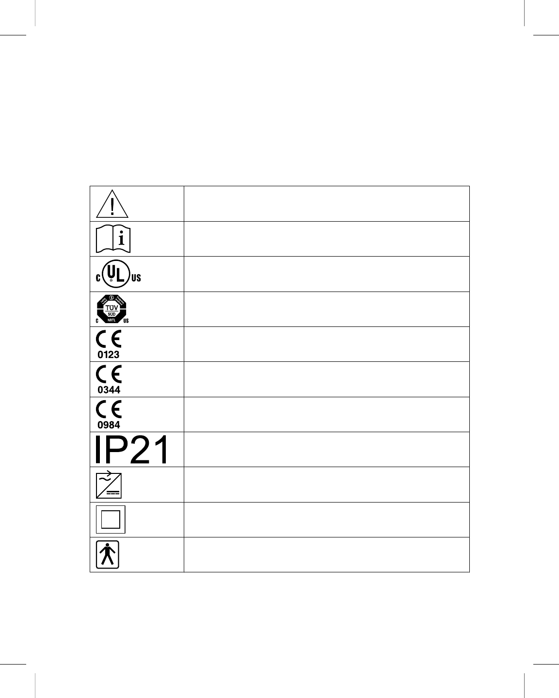
1.1 Explanation of packaging and product symbols
Refer to the package label and product to see which symbols apply to this product.
Caution
Consult instructions for use
The product complies with both Canadian and U.S. requirements for meet-
ing UL safety standards.
System meets the applicable Canadian [C22.2-601.1-M90 (R2001)
CAN/CSA C22.2 No. 60601-1-08] and US (UL 60601-1:2003) electrical
safety standard requirements.
Conformité Européenne (European Conformity). This symbol means that
the device fully complies with European Directive AIMD 90/385/EEC (NB
0123). (Applies to Medtronic hardware and software only.)
Conformité Européenne (European Conformity). This symbol means that
the device fully complies with European Directive AIMD 90/385/EEC (NB
0344). (Applies to Vitatron desktop software only.)
Conformité Européenne (European Conformity). This symbol means that
the device fully complies with the essential requirements of R&TTE Direc-
tive 1999/5/EC (NB 0984). (Applies to Bluetooth only.)
This product conforms to IP21. There are no openings that allow the user
to insert a finger or similar sized objects. The product is resistant to dripping
water or vertically falling drops.
Use only with specified power supply.
Class II ME Equipment
Type BF applied part
Printing instructions: doc#163256; refer to 'Reference manuals' row in the applicable table. 501346-089
Medtronic CARELINK ENCORE™ 29901
8 Reference Manual
M945141A001B Medtronic Confidential Composed: 2012-04-26 10:35:22
XSL-Stylesheet H - Reference manual 12-MAY-2011
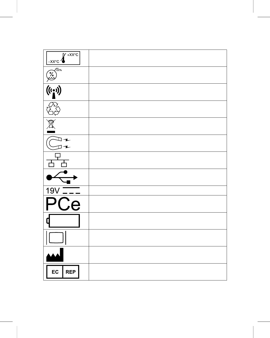
Temperature limitation
Humidity limitation
RF transmitter
Notice of proper disposal.
Do not dispose of this product in the unsorted municipal waste stream.
Dispose of this product according to local regulations. See http://recy-
cling.Medtronic.com for instructions on proper disposal of this product.
Caution: Strong magnet
Network connection port
USB port
DC input
ExpressCard
Battery
VGA monitor
Manufacturer/Date of Manufacture
Authorized representative in the European community
Printing instructions: doc#163256; refer to 'Reference manuals' row in the applicable table. 501346-089
Medtronic CARELINK ENCORE™ 29901
Reference Manual 9
M945141A001B Medtronic Confidential Composed: 2012-04-26 10:35:22
XSL-Stylesheet H - Reference manual 12-MAY-2011
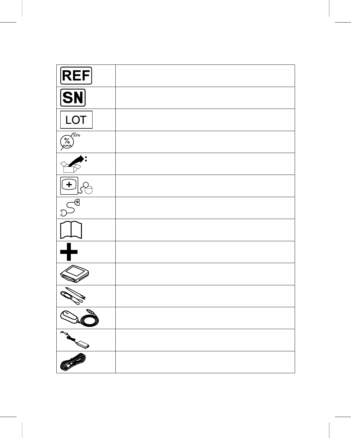
Reorder number
Serial number
Lot number
Humidity limitation
Package contents
Programmer, software installed
Power cord
Product documentation
Accessories
Programmer
Stylus / tether
Programming head
Power supply
Power cord
Printing instructions: doc#163256; refer to 'Reference manuals' row in the applicable table. 501346-089
Medtronic CARELINK ENCORE™ 29901
10 Reference Manual
M945141A001B Medtronic Confidential Composed: 2012-04-26 10:35:22
XSL-Stylesheet H - Reference manual 12-MAY-2011
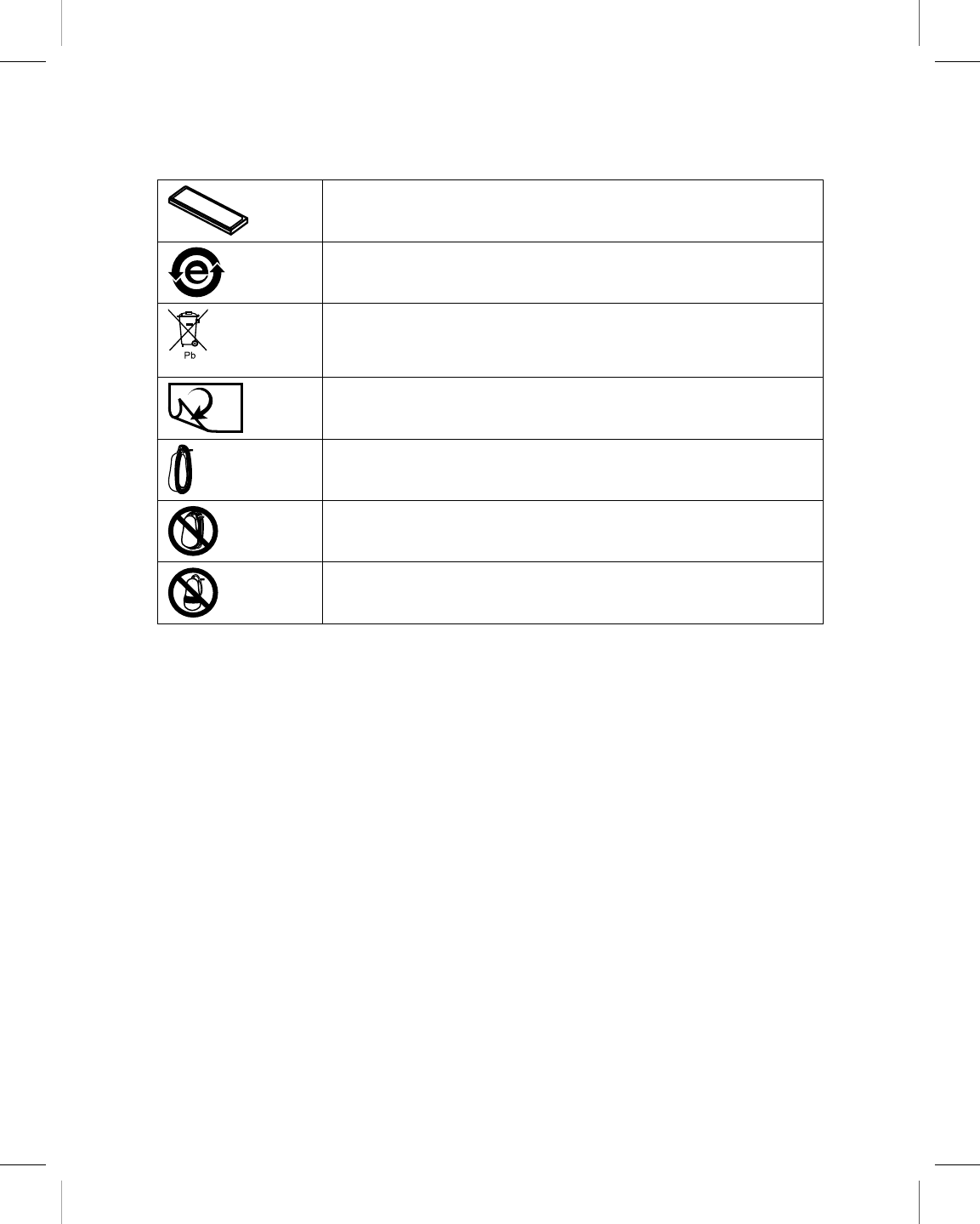
Battery
China RoHS
This product contains lead (Pb). Do not dispose of this product in the
unsorted municipal waste stream. Dispose of this product according to
local regulations. See http://recycling.Medtronic.com for instructions on
proper disposal of this product.
Turn the page
Store programming head
Do not wrap cord behind head
Do not wrap cord around head
1.2 About this guide
This guide describes the features and functions of the CareLink Encore 29901 Programmer
(referred to as the “programmer”).
Note: Screen images in this guide are for reference only. The content and presentation may
vary depending on user selections, desktop, and device being interrogated.
1.3 Description
The CareLink Encore 29901 Programmer is a portable, line-powered (AC) or
battery-powered microprocessor-based system with software to interrogate and program
Medtronic and Vitatron implantable devices. Other features include:
●Automated software updates using a wireless or local area network (LAN) connection.
This connection allows the programmer to program new devices and to provide new
features as they become available.
●A large, bright screen that is adjustable for viewing when sitting or standing.
Printing instructions: doc#163256; refer to 'Reference manuals' row in the applicable table. 501346-089
Medtronic CARELINK ENCORE™ 29901
Reference Manual 11
M945141A001B Medtronic Confidential Composed: 2012-04-26 10:35:22
XSL-Stylesheet H - Reference manual 12-MAY-2011

1.4 Intended use
The programmer is intended to be used to interrogate and program Medtronic and Vitatron
implantable devices.
1.5 Warnings
These warnings apply in general to using the programmer for programming implantable
device parameter settings. For more information related to specific implantable device
models, see the reference guides for the implantable device and the programmer software.
Battery charging – Use the programmer for charging batteries by installing the battery and
connecting the power supply. Unapproved charging equipment may damage the battery or
cause excessive heating, battery case rupture, or ignition of the battery cells. Use of a
damaged battery may damage equipment or cause user or patient injury.
Battery disposal – Do not dispose of batteries in fire, in order to avoid the risk of explosion.
Battery exposure – Exposing the battery to cold temperatures may result in a loss of
performance and shortened battery service life. Use of a damaged battery may cause injury,
damage equipment, or impact user or patient safety.
Battery handling – Do not puncture batteries. Do not disassemble batteries as this can
generate a gas that may irritate the throat and lungs. If the battery is opened, lithium in the
battery may react with moisture and generate heat or fire, which could result in injury.
Battery overheating – Do not store the programmer battery in direct sunlight, inside a car,
or in an enclosed space in extremely hot weather. Overheating the battery may result in a
loss of performance and shortened battery service life. The battery contains built-in thermal
protection circuitry that prevents the battery from charging when hot. Excessive heating of
the battery may cause battery case rupture or ignition of the battery cells.
Battery replacement – If you receive a message on the programmer to replace the battery,
you need to replace the battery with a new battery. Use of a failed battery will reduce
programmer operating time and may cause user or patient injury. For more information, see
Section 2.4.
Connection of external devices – Additional equipment connected to medical electrical
equipment must comply with the respective IEC or ISO standards (for example, IEC 60950
for data processing equipment). All configurations must comply with the requirements for
medical electrical systems (see IEC 60601-1-1 or clause 16 of the 3rd edition of IEC
60601-1, respectively). Anyone connecting additional equipment to medical electrical
equipment configures a medical system and is therefore responsible that the system
complies with the requirements for medical electrical systems. Local laws take priority over
the above mentioned requirements. If in doubt, consult your local Medtronic representative
or the technical service department.
Printing instructions: doc#163256; refer to 'Reference manuals' row in the applicable table. 501346-089
Medtronic CARELINK ENCORE™ 29901
12 Reference Manual
M945141A001B Medtronic Confidential Composed: 2012-04-26 10:35:22
XSL-Stylesheet H - Reference manual 12-MAY-2011

Damage due to impact – Do not use the programmer if it has sustained impact damage.
Internal components may be damaged or exposed. Use of damaged equipment may impact
user or patient safety.
Defective equipment – If technical and safety inspection reveals a defect that could harm
the patient, clinicians, or third parties, the programmer should not be used until it has been
properly repaired. The operator must immediately notify Medtronic or Vitatron of these
defects.
Diagnostic ECG – Do not use the programmer ECG display for recording or diagnosis.
Use a separate ECG device if recording or diagnostic ECG capabilities are required.
Electric shock risk – Do not simultaneously touch the patient and any metal parts of the
programmer, such as the USB port or the power connector, as voltage may be present.
Application of voltage to the patient may impact user or patient safety.
Equipment compatibility – The programmer must be used only for interrogating and
programming compatible Medtronic or Vitatron implantable devices. If the programmer is
used on other implanted devices, direct stimulation through energy coupling may occur.
The programmer is not compatible with programmable devices of other manufacturers.
Flammable anesthetic mixture – The programmer is not suited for use in the presence
of a flammable anesthetic mixture.
High sound pressure levels – The programmer speaker may emit alert tones at high
sound pressure levels. Consider speaker position when setting up the programmer, and
dismiss alerts as soon as possible, in order to avoid hearing damage. Exposure to high
sound pressure levels may damage hearing and impact patient health.
Importance of reference documentation – Implantable device programming should be
done only after careful study of the reference guide for the implantable device and after
careful determination of appropriate parameter values based on the patient’s condition and
pacing system used. The implantable device reference guide contains a complete
description of implantable device operation and important information, such as indications
for use, contraindications, warnings, and precautions. The instructions contained in this
reference guide and the reference guide supplied with the programmer software are limited
to the mechanics of setting up the programmer and selecting the correct options for the
desired programming function. Improper use of the programmer could result in erroneous
or inadvertent programming and improper operation of telemetry and measurement
functions.
Internal electrodes – Do not connect the programmer to wires or electrodes internal to the
body. The programmer is designed to be medically safe only when attached to surface
electrodes.
Internal RTC battery replacement – The real-time clock (RTC) battery, located inside the
programmer on a circuit board, is not replaceable by the user. The battery needs
Printing instructions: doc#163256; refer to 'Reference manuals' row in the applicable table. 501346-089
Medtronic CARELINK ENCORE™ 29901
Reference Manual 13
M945141A001B Medtronic Confidential Composed: 2012-04-26 10:35:22
XSL-Stylesheet H - Reference manual 12-MAY-2011

replacement if the time-of-day clock cannot keep time. Return the programmer to Medtronic
for replacement. Use of damaged equipment may impact user or patient safety.
Light-emitting diode (LED) radiation – This device contains Class 1M LEDs. To avoid
eye injury, do not view LEDs directly with optical instruments or magnifiers.
Magnetic Resonance (MR) Unsafe – The programmer is MR Unsafe. Do not bring the
programmer into Zone 4 (magnet room), as defined by the American College of Radiology.
Measurement function – The programmer is also designed to detect and measure pulse
rate, AV interval and pulse width, and implantable device artifacts. The device takes these
digital measurements with the assistance of optional skin electrodes. Medtronic and
Vitatron make no claims or warranties as to the effectiveness of the programmer as a
diagnostic tool to the physician.
Modification of equipment – Do not modify this equipment. Modifications may reduce
system effectiveness and impact user or patient safety.
Programmer ventilation – Ensure that the fan is running and programmer ventilation
openings are not blocked, in order to prevent overheating. Overheating may cause
equipment damage or user or patient safety.
Supply mains with protective earth – To avoid the risk of electric shock, connect the
power supply only to a hospital-grade supply mains receptacle which has a protective earth.
If the integrity of the supply mains protective earth is in doubt, operate the device using the
charged internal battery only.
Use of approved components – Use the specified, Medtronic-supplied power cord,
power supply, battery, and components only. The battery is a custom component designed
to be used solely in the programmer; replace with and use only the battery supplied by
Medtronic. Use of unapproved components may reduce device effectiveness or impact user
or patient safety.
Use of unapproved ports and connections – Do not connect unapproved or
unsupported equipment or components, such as a docking station, to the programmer. Use
of unapproved components may damage equipment or impact user or patient safety.
Use of unapproved power supply – Use only the Medtronic-supplied power supply model
26907 (APS100EM-190530) with the programmer. Use of an unapproved power supply
may damage equipment or impact user or patient safety.
Use of wireless devices – The programmer incorporates radio-frequency (RF)
communications components which may affect other devices and equipment in the medical
environment. The use of wireless devices in the medical environment must be evaluated
and authorized by the responsible organization. RF interference may affect device
performance.
Printing instructions: doc#163256; refer to 'Reference manuals' row in the applicable table. 501346-089
Medtronic CARELINK ENCORE™ 29901
14 Reference Manual
M945141A001B Medtronic Confidential Composed: 2012-04-26 10:35:22
XSL-Stylesheet H - Reference manual 12-MAY-2011

1.6 Precautions
Care in handling ECG cable wire – Do not pull on the insulated cable wire to disconnect
the cable. Tension on the insulated cable wire may result in damage to the cable.
Electrocautery/external defibrillation – Do not position the programming head over an
implanted device during electrocautery or external defibrillation procedures.
Do not immerse – Take care to prevent liquid from entering the programmer and
programming head. Do not immerse the programmer or any accessories in any liquid or
clean them with aromatic or chlorinated hydrocarbons.
Autoclaving – Do not autoclave the programming head or ECG cable and lead wires.
Electromagnetic interference (EMI) – The programming head has been tested for
compliance with industrial and medical EMI regulations. Any use outside the patient
environment may result in the programming head malfunctioning.
Radio-frequency (RF) interference – Portable and mobile RF communications
equipment can interfere with the operation of the programmer. Although this system has
been approved, there is no guarantee that it will not receive interference or that any particular
transmission from this system will be free from interference.
Damaged equipment – If the case of the programmer is cracked or if any of the connectors
are damaged, contact your Medtronic or Vitatron representative. If there is insulation
damage to the power cord or accessory cables or if any of the wall or equipment plugs are
damaged, replace the part and dispose of it according to local regulations or return the part
to Medtronic.
Electrode quality – Use of high-quality silver/silver chloride (Ag/AgCl) electrodes can
minimize the occurrence of small DC voltages that can block the ECG signal. Use electrodes
that are fresh and from the same box. Prepare the patient’s skin according to the directions
provided with the electrodes.
Avoid damage from programming head – Keep the programming head away from any
device or material that will be damaged by the magnetic field, including magnetic media,
watches, and other electronic devices.
Finger injury – Do not place fingers in the hinge area when opening or closing the stand.
Do not place fingers near the storage doos when opening or closing the storage doors. A
painful pinch may result.
Programmer and power cord positioning – Position the programmer and power cord so
that the power cord can be easily accessed and disconnected. If it is necessary to remove
the programmer from the AC mains, the power cord is the power disconnect at the mains
outlet.
Printing instructions: doc#163256; refer to 'Reference manuals' row in the applicable table. 501346-089
Medtronic CARELINK ENCORE™ 29901
Reference Manual 15
M945141A001B Medtronic Confidential Composed: 2012-04-26 10:35:22
XSL-Stylesheet H - Reference manual 12-MAY-2011

Connection or disconnection of programming head – Do not connect or disconnect
the programming head while the programmer power is on. Disconnecting the programming
head causes an error that requires the programmer to be shut down and restarted.
Product and packaging labels and information – If labels or information appear to be
missing from the product or packaging, contact your local Medtronic representative at the
address and telephone number located on the back cover of this document.
1.6.1 Environmental precautions
To ensure safe and effective operation, use the device with care to avoid damage to the
programmer from environmental factors that may impair its function. Care is exercised in
design and manufacturing to minimize damage to devices under normal use. However,
electronic devices are susceptible to many environmental stresses including, but not limited
to, the following examples.
●The unit is designed to be used indoors in a clinic or hospital.
●The unit should not be dropped or mishandled in such a manner as to cause physical
damage to the unit. This may impair device function. Even if the unit works immediately
after being dropped, operational damage may have occurred that may not be observed
until some future time.
●Fluid should not be spilled on the unit. Even though care is exercised in design and
manufacture of the unit to minimize leakage, fluid incursion may occur, which could
impair functioning of the unit.
●The programmer may be affected by electrostatic discharge (ESD). In an environment
likely to cause ESD, such as a carpeted floor, discharge any charge collected on your
body before touching the device.
●The programmer should be placed on a table or other hard surface and positioned to
avoid contact with the physician or patient; it is not intended to be used while supported
by or in contact with the physician or patient.
●The programmer should maintain a distance of at least 20 cm away from patients and
clinicians when the programmer is using Wi-FI or Bluetooth radios.
●Printers and other connected office equipment should be placed at least 1.5 m from the
patient environment.
●Electrically-operated medical devices, such as the programmer require special care (in
terms of electromagnetic compatibility) when being installed. Refer to the
accompanying insert: Electromagnetic Compatibility Declaration.
●Do not open the device. The programmer is constructed to minimize risk from
environmental factors. Opening the unit may make the unit susceptible to environmental
factors and may expose the patient or user to hazardous voltage or current.
Printing instructions: doc#163256; refer to 'Reference manuals' row in the applicable table. 501346-089
Medtronic CARELINK ENCORE™ 29901
16 Reference Manual
M945141A001B Medtronic Confidential Composed: 2012-04-26 10:35:22
XSL-Stylesheet H - Reference manual 12-MAY-2011

●Rapid temperature changes may affect proper operation. Always allow the temperature
to stabilize in the environment in which the device is used before using the device.
●Prolonged storage or operation of the device in high humidity may affect proper
operation.
If there is any concern that damage has occurred, the unit should be returned to Medtronic
or Vitatron for inspection and any needed repair.
Besides these listed examples, various other environmental factors may impair proper
performance of the unit in the hospital setting. Always use good health management
practices to prevent environmental damage to the unit.
1.7 Declaration of Conformity
Medtronic declares that this product is in conformity with the essential requirements of
Directive 1999/5/EC on Radio and Telecommunications Terminal Equipment and Directive
90/385/EEC on Active Implantable Medical Devices (AIMD).
For additional information, contact Medtronic or Vitatron at the telephone numbers and
addresses provided on the back cover.
1.8 Regulatory compliance
1.8.1 US Federal Communications Commission (FCC)
FCC ID:LF529901 (for programmer and programming head)
1.8.2 The following provision applies to the low frequency communications
system in the device:
This device complies with Part 15 of the FCC Rules. Operation is subject to the following
two conditions: (1) this device may not cause harmful interference, and (2) this device must
accept any interference received, including interference that may cause undesired
operation. The user is cautioned that changes or modifications not expressly approved by
the party responsible for compliance could void the user’s authority to operate the
equipment.
Printing instructions: doc#163256; refer to 'Reference manuals' row in the applicable table. 501346-089
Medtronic CARELINK ENCORE™ 29901
Reference Manual 17
M945141A001B Medtronic Confidential Composed: 2012-04-26 10:35:22
XSL-Stylesheet H - Reference manual 12-MAY-2011

1.9 Programmer functions
The following list summarizes some of the programmer functions. Specific functions depend
on the implantable device model being programmed or monitored and the software
installed.
1.9.1 Programming functions:
●Permanent and temporary adjustment of parameter values.
●Selection of nominal parameter values established by Medtronic, Vitatron or by the user.
●Emergency button for VVI pacing.
1.9.2 Telemetry functions:
●Automatic detection of the device model, and automatic application start-up, if the
programming head is in proper position when the programmer is turned on.
●Automatic confirmation of a programmed change.
●Reporting of currently programmed parameter values in effect, battery status of the
implanted device, saved implantable system information, and patient status
information.
●Display and save as a PDF file an atrial and/or ventricular intracardiac electrogram
(EGM) taken from the electrodes of the implantable device lead system or Marker
Channel telemetry.
1.9.3 ECG functions:
●Live Rhythm Monitor window on programming and telemetry data screens provides a
continuous view of the patient’s ECG.
●Full-window Live Rhythm display including a freeze option and an amplitude adjustment
feature; Live Rhythm display includes Marker Channel telemetry, EGM waveforms, or
both when available.
●Continuous multi-channel storage.
●Stimulation threshold test functions.
●Direct measurement of pulse rate, AV interval, and pulse width from the desktop.
Warning: Do not use the programmer ECG display for recording or diagnosis. Use a
separate ECG device if recording or diagnostic ECG capabilities are required.
Printing instructions: doc#163256; refer to 'Reference manuals' row in the applicable table. 501346-089
Medtronic CARELINK ENCORE™ 29901
18 Reference Manual
M945141A001B Medtronic Confidential Composed: 2012-04-26 10:35:22
XSL-Stylesheet H - Reference manual 12-MAY-2011

1.9.4 Software update function:
●Automated software updates using a wireless or local area network (LAN) connection.
This connection allows the programmer to program new devices and to provide new
features as they become available.
●Updates available from Medtronic personnel.
●Clinical software applications that have Uninstall Software capability may be removed
using the programmer desktop.
1.10 Security features of the programmer
Good security practices are needed to protect patient data and the integrity of any
network-connected product. The programmer incorporates features that facilitate
management of security. These features work in conjunction with the security practices of
hospitals and clinics to provide safe and secure operation of the programmer and protect
the attached network.
1.10.1 How the programmer promotes security
All installed software has been approved by Medtronic. It is not possible to install general
purpose software on the programmer. Controlling installed software minimizes the potential
for vulnerabilities. Internal software that runs the programmer is locked from change. Every
time the programmer is started, a clean version of the installed software is used.
Patient data is encrypted. The length of time that patient data can be stored on the
programmer is limited. The programmer limits patient data stored on the programmer by
deleting it after at most 14 days. When patient data is removed from the programmer, it is
completely erased so that it is no longer recoverable.
The programmer limits how it communicates on a network. When communicating on a
network, the programmer uses industry-accepted protocols for authenticating servers and
encrypting transmitted data. Only required network connections are open. Network
communications are originated by the programmer. Unauthorized software is not permitted
to originate communications with the programmer.
Unsupported hardware, including unsupported USB devices, is ignored by the programmer
and is not accessed.
Medtronic continues to work with its partners to analyze emerging threats and evaluate
potential impact on the programmer.
Printing instructions: doc#163256; refer to 'Reference manuals' row in the applicable table. 501346-089
Medtronic CARELINK ENCORE™ 29901
Reference Manual 19
M945141A001B Medtronic Confidential Composed: 2012-04-26 10:35:22
XSL-Stylesheet H - Reference manual 12-MAY-2011

1.10.2 What hospitals and clinics can do to promote the security of
programmers
Maintain good physical controls over the programmer. Having a secure physical
environment prevents access to the internals of the programmer.
Only connect the programmer to managed, secure networks.
Update the software on the programmer when Medtronic updates are available.
1.10.3 What to do if you suspect the programmer has been compromised
If you believe that the programmer has been compromised by a security threat, turn off the
programmer, disconnect it from the network, then restart the system. Discontinue use of the
programmer if it does not behave as expected. Contact your Medtronic or Vitatron
representative for further assistance.
1.11 Software requirements
The programmer requires software from Medtronic and Vitatron to operate. Once installed,
the software remains on the programmer.
Medtronic and Vitatron periodically update the software to add functions to the programmer.
The programmer will not operate properly without the appropriate software installed. If the
programmer does not operate properly, check the version of software that is loaded on the
programmer, and update it if necessary.
1.12 Compatible components
The following compatible components are available for the programmer:
●Battery 26902
●EC 2090 ECG Cables, Electrode Lead Wires, and Plug
●EC ECL 2090 ECG Cables, Electrode Lead Wires, and Plug
●Power Cord 26906
●Power Supply 26907 (APS100EM-190530)
●Programming Head 26901
●Stylus and Tether 26905
Contact your local Medtronic representative to order them.
Printing instructions: doc#163256; refer to 'Reference manuals' row in the applicable table. 501346-089
Medtronic CARELINK ENCORE™ 29901
20 Reference Manual
M945141A001B Medtronic Confidential Composed: 2012-04-26 10:35:22
XSL-Stylesheet H - Reference manual 12-MAY-2011

The following components are available as repair parts during authorized service only:
●Articulating Stand 26909
●Storage Doors 26908
1.13 Obtain technical manuals
Medtronic technical manuals, including the manual you are reading, are available in a
number of different formats from the Medtronic eManuals website listed on the back cover
of this manual. The website offers real-time access to the latest version of manuals 24 hours
per day, seven days per week. Manuals can be viewed online, downloaded for viewing or
printing, or ordered from the website.
All manuals are available online in English. Most manuals are also available in additional
languages in online, CD-ROM, or paper format. New manuals are added to this site
regularly. If you do not find the manual you want, contact your Medtronic or Vitatron
representative.
Your order for CD-ROM or printed versions of manuals ships from our facility within 24 hours
and should reach you within 3 business days. If you need a copy before the shipment arrives,
download the manual and print it, or contact your Medtronic or Vitatron representative.
1.13.1 Access the eManuals website
1. Point your browser to the address listed on the back cover of this manual.
2. Select location and language, and click [Continue].
3. Select one or more manual languages, and click [Continue].
To see lists of CRDM manuals, click the desired category on the left of the screen. You can
also search for manuals using a product name or model number.
Printing instructions: doc#163256; refer to 'Reference manuals' row in the applicable table. 501346-089
Medtronic CARELINK ENCORE™ 29901
Reference Manual 21
M945141A001B Medtronic Confidential Composed: 2012-04-26 10:35:22
XSL-Stylesheet H - Reference manual 12-MAY-2011
2 Set up the programmer
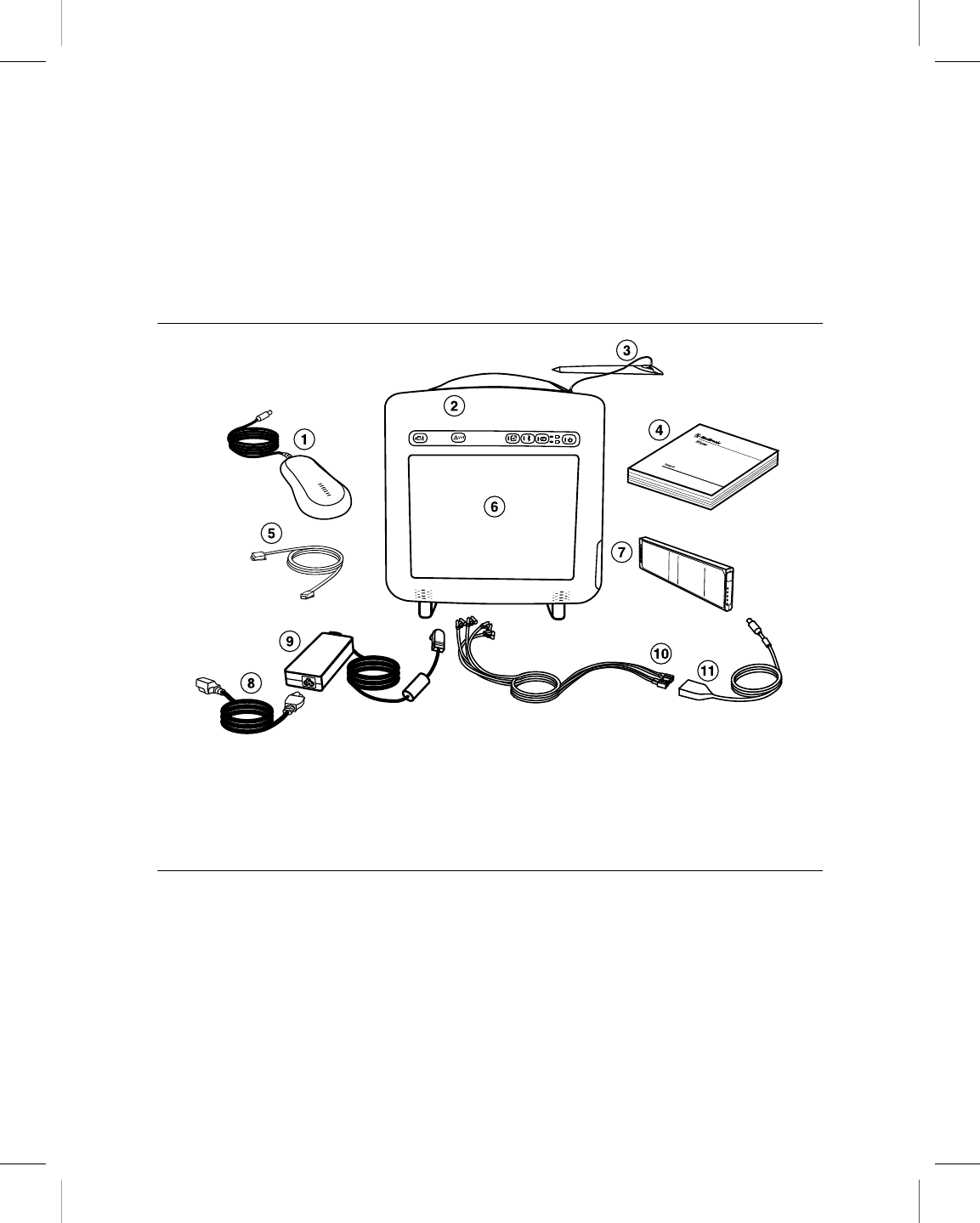
2.1 System components
Figure 1. Programmer components - front view
1 Programming head
2 Button panel
3 Stylus and Tether
4 Product documentation
5 Ethernet cable (not supplied)
6 Display screen
7 Battery
8 Power cord
9 Power supply
10 Electrode leads (not supplied)
11 ECG cable with plug (not supplied)
Warning: Use only the specified, Medtronic-supplied power cord, power supply, and
components. Use of unapproved components may reduce device effectiveness or impact
patient health.
Programming head – Provides the communication link between the programmer and the
patient’s implantable device. The programming head contains a strong permanent magnet,
radio-frequency (RF) transmitter and receiver, and light array. It must be held over the
implantable device during a program or interrogate operation.
Printing instructions: doc#163256; refer to 'Reference manuals' row in the applicable table. 501346-089
Medtronic CARELINK ENCORE™ 29901
22 Reference Manual
M945141A001B Medtronic Confidential Composed: 2012-04-26 10:35:22
XSL-Stylesheet H - Reference manual 12-MAY-2011
Display screen – Display can be positioned horizontally, vertically, or at an angle.
Programming options are selected on the screen with the stylus.
Stylus – Used to select options on the display screen. Predetermined options are selected
by applying the stylus to the screen.
Ethernet cable – Used to connect the programmer to the clinic’s network. The Ethernet
cable must be Category 5 or better. (Not supplied by Medtronic.)
Power cord – Connects the power supply to an AC power outlet.
Power supply – Connects the programmer to the power cord.
Electrode leads/ECG cable – Connects the programmer to skin electrodes on the patient
for ECG and measurement functions requiring surface detection of cardiac and implantable
device signals. Four color-coded lead wires connect the cable to standard, disposable skin
electrodes applied to the patient. (The electrode leads/ECG cables are optional.)
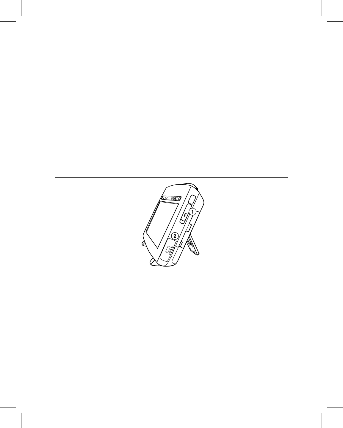
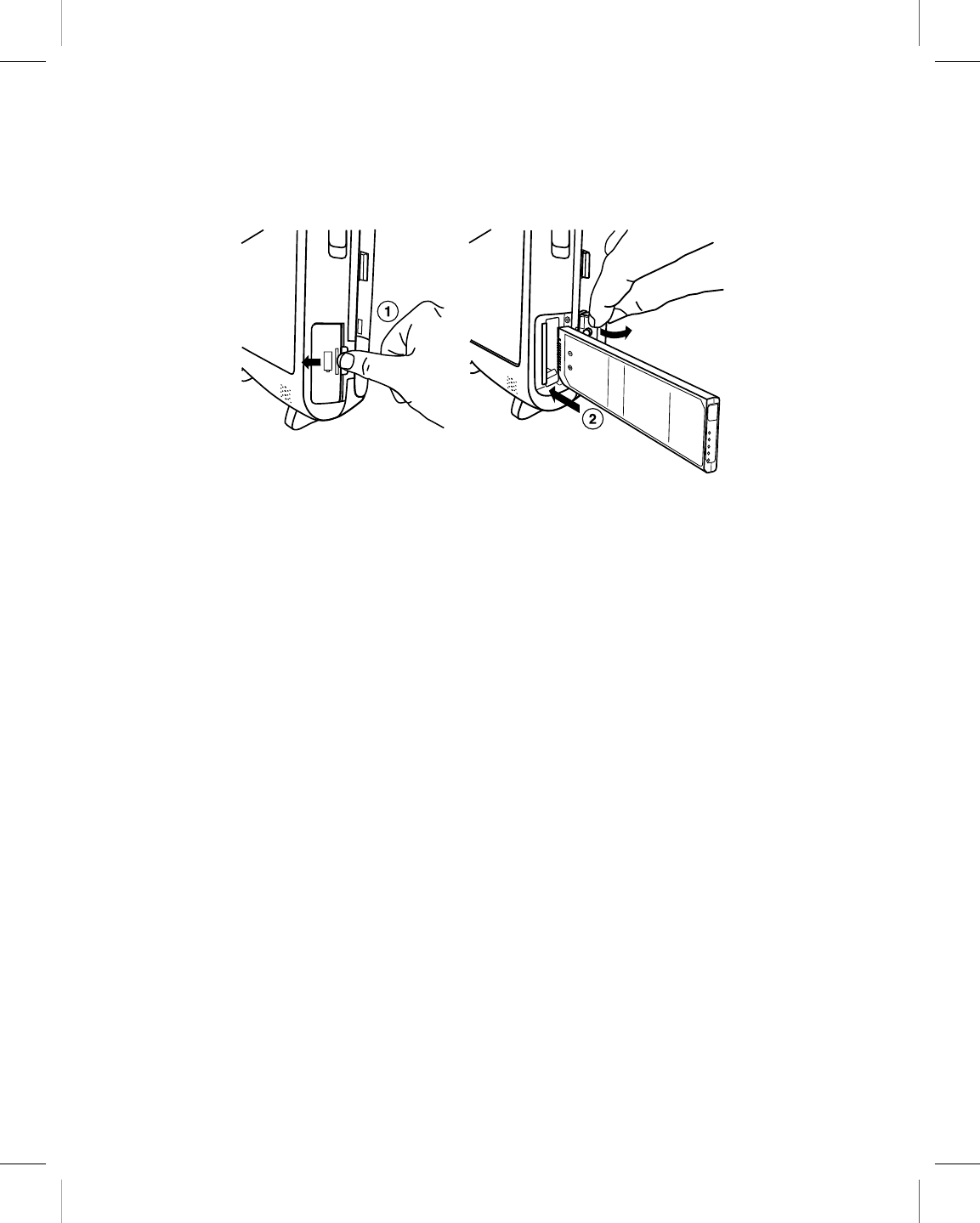
Figure 2. Right view
1 ExpressCard slot
2 Battery cover
ExpressCard slot – Intended for future use.
Battery cover – Covers the battery compartment. Push the cover forward and slide it out
to insert or remove the battery.
Printing instructions: doc#163256; refer to 'Reference manuals' row in the applicable table. 501346-089
Medtronic CARELINK ENCORE™ 29901
Reference Manual 23
M945141A001B Medtronic Confidential Composed: 2012-04-26 10:35:22
XSL-Stylesheet H - Reference manual 12-MAY-2011
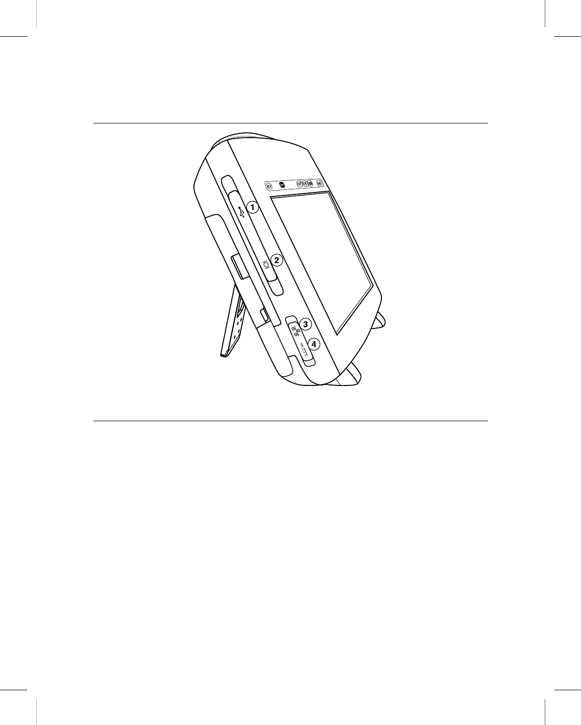
Figure 3. Left view
1 USB ports
2 VGA output port
3 Integrated Ethernet
4 Power input
USB port(s) – Allows installation of software, software updates, and future device
application installations. The USB port can also be used to connect to a USB printer or a
USB flash drive.
VGA output port – Allows porting the screen image of the programmer to an external VGA
monitor or for conversion of the output signal to NTSC/PAL format for presentation on a
television monitor.
Integrated Ethernet – Allows the programmer to connect to the Software Distribution
Network and the Paceart data management system using an Ethernet connection.
Power input – Used to connect the programmer to an AC power outlet using the power
supply and power cord.
Printing instructions: doc#163256; refer to 'Reference manuals' row in the applicable table. 501346-089
Medtronic CARELINK ENCORE™ 29901
24 Reference Manual
M945141A001B Medtronic Confidential Composed: 2012-04-26 10:35:22
XSL-Stylesheet H - Reference manual 12-MAY-2011
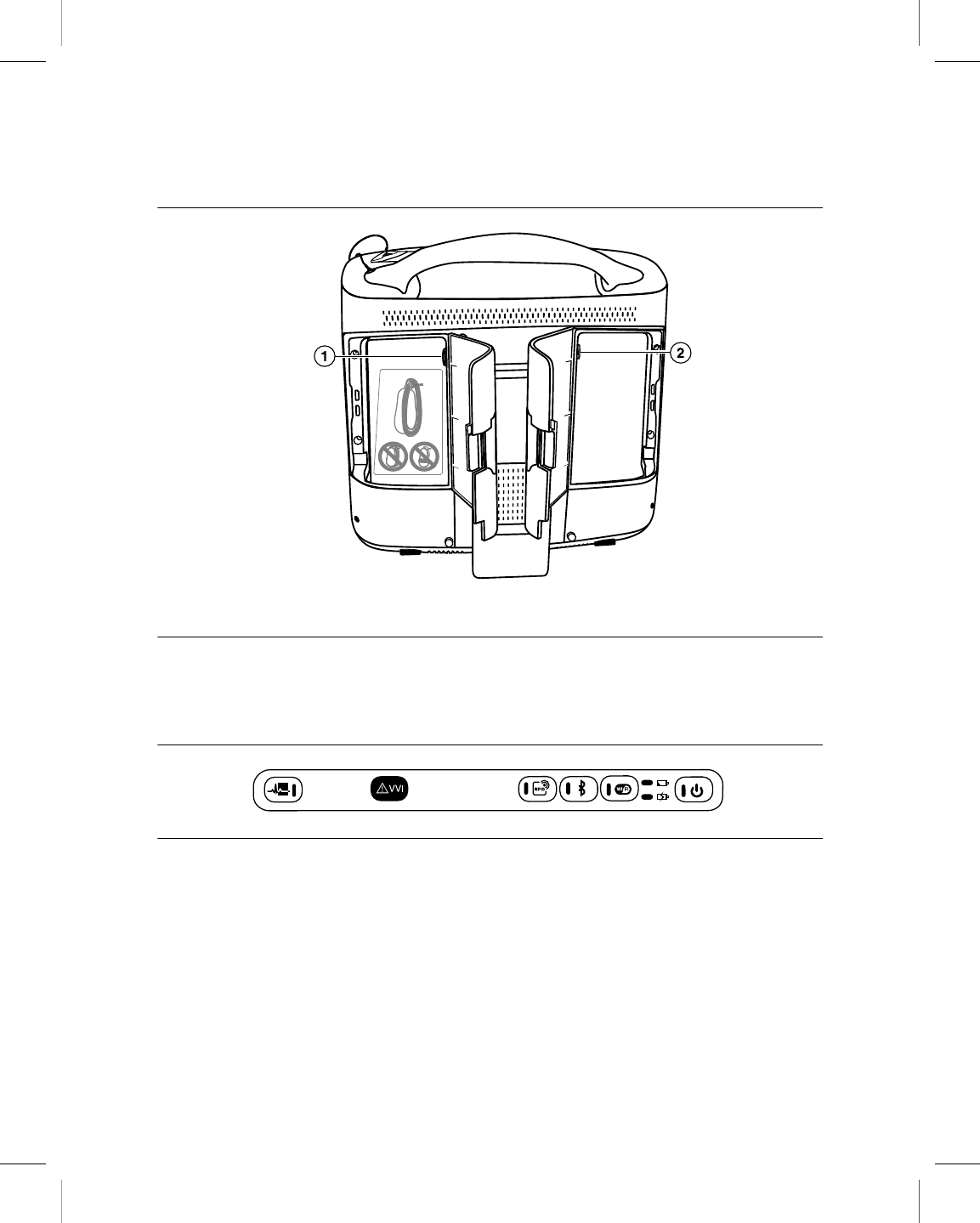
Figure 4. Back view (doors open)
1 Programming head connector
2 ECG cable connector
2.2 Programmer button panel
Figure 5. Programmer button panel
The programmer button panel contains these buttons and indicators:
Printing instructions: doc#163256; refer to 'Reference manuals' row in the applicable table. 501346-089
Medtronic CARELINK ENCORE™ 29901
Reference Manual 25
M945141A001B Medtronic Confidential Composed: 2012-04-26 10:35:22
XSL-Stylesheet H - Reference manual 12-MAY-2011
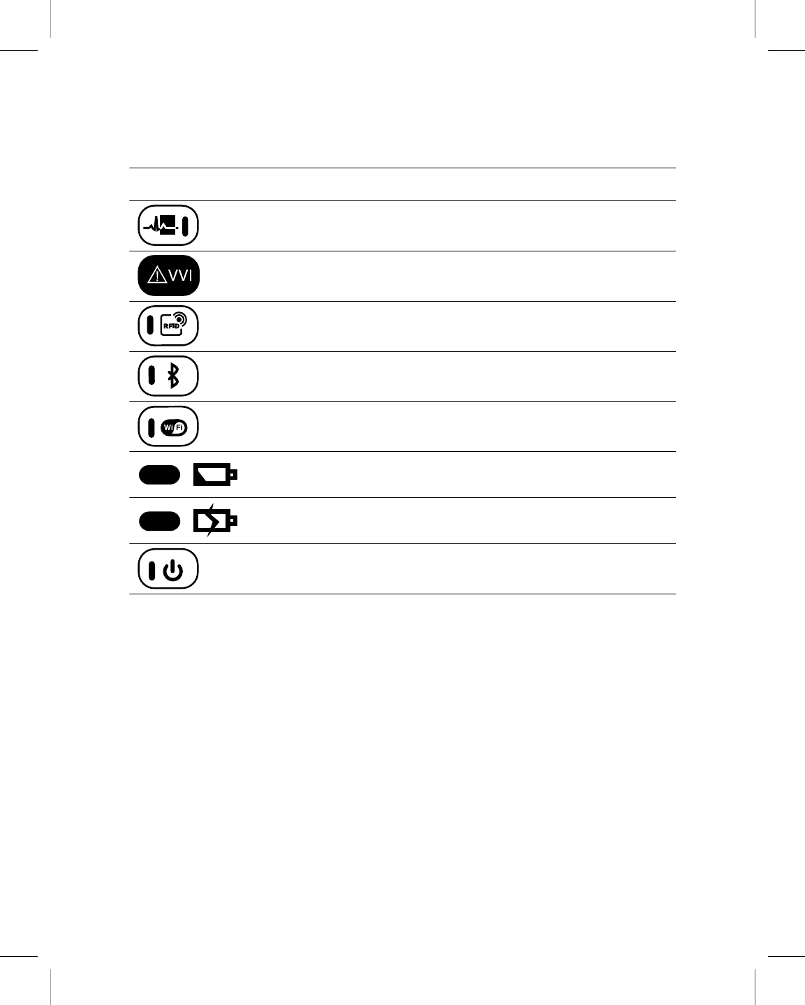
Table 1. Buttons and indicators on the programmer button panel
Button or indi-
cator Name Function
Electronic Strip Chart
(eStrip) button
Used to insert a highlight into the recorded Elec-
tronic Strip Chart (eStrip) waveform data.
Emergency VVI button Provides immediate access for emergency VVI
pacing during a session.
RFID button Intended for future use.
Bluetooth button Used to enable or disable Bluetooth power.
Wi-Fi button Used to enable or disable Wi-Fi power.
Battery Status indicator Provides information about the status of the bat-
tery.
Battery Charge indicator Provides information about the charge of the bat-
tery.
Power button Turns on and turns off the programmer.
2.3 Basic setup
Before setting up the programmer, select a sturdy location for it without blocking the air vents
on the back. The programmer uses an AC power supply and has a backup battery. To use
the power supply, the location of the programmer must be near a hospital-grade supply
mains receptacle which has a protective earth.
This section describes how to:
●Position the programmer
●Connect the power supply
●Install the battery
●Connect the programming head
Printing instructions: doc#163256; refer to 'Reference manuals' row in the applicable table. 501346-089
Medtronic CARELINK ENCORE™ 29901
26 Reference Manual
M945141A001B Medtronic Confidential Composed: 2012-04-26 10:35:22
XSL-Stylesheet H - Reference manual 12-MAY-2011
●Connect the ECG cable
●Turn on the programmer
●Troubleshoot potential interference
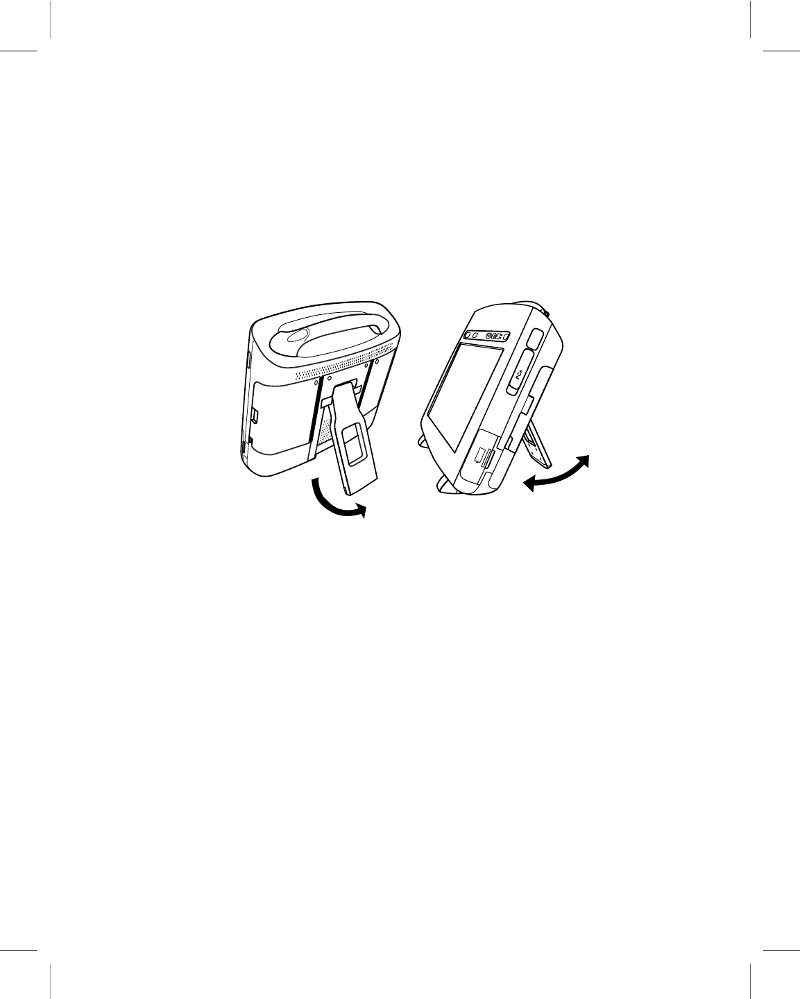
2.3.1 Position the programmer
The programmer can be positioned horizontally or at an angle.
1. To position the programmer at an angle, pull out the stand on the rear of the
programmer.
2. Place it at a comfortable viewing angle.
Caution: Do not place fingers in the hinge area when opening or closing the stand. A painful
pinch may result.
Printing instructions: doc#163256; refer to 'Reference manuals' row in the applicable table. 501346-089
Medtronic CARELINK ENCORE™ 29901
Reference Manual 27
M945141A001B Medtronic Confidential Composed: 2012-04-26 10:35:22
XSL-Stylesheet H - Reference manual 12-MAY-2011
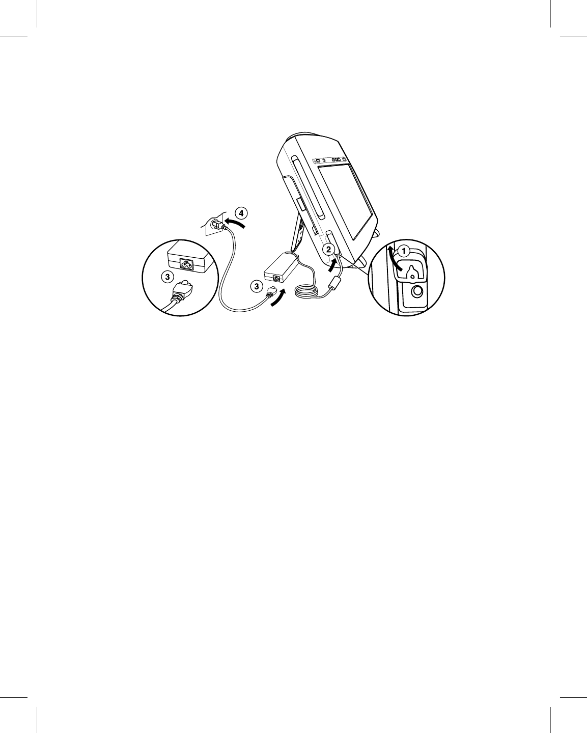
2.3.2 Connect the power supply
1. Open the power input cover on the lower left side of the programmer.
2. Plug the power supply into the programmer.
3. Plug the power cord into the power supply.
4. Position the programmer and power cord so that the power cord can be easily
accessed and disconnected.
5. Plug the power cord into the AC power outlet (AC mains).
Note: If it is necessary to remove the programmer from the AC power outlet (AC mains),
the power cord is the power disconnect at the mains outlet.
Warnings:
●To avoid the risk of electric shock, connect the power supply only to a hospital-grade
supply mains receptacle that has a protective earth. If the integrity of the supply mains
protective earth is in doubt, operate the device using the charged internal battery only.
●Use only the specified, Medtronic-supplied power cord, power supply, and
components. Use of unapproved components may reduce device effectiveness or
impact patient health.
Printing instructions: doc#163256; refer to 'Reference manuals' row in the applicable table. 501346-089
Medtronic CARELINK ENCORE™ 29901
28 Reference Manual
M945141A001B Medtronic Confidential Composed: 2012-04-26 10:35:22
XSL-Stylesheet H - Reference manual 12-MAY-2011
2.3.3 Install the battery
1. Open the battery door on the lower right side of the programmer by pressing forward
on the battery door recess and flipping the door to the left.
2. Slide the battery in until you hear it click into position. The battery is kept in position by
a hook located on the bottom of the opening.
3. Close the battery door.
Notes:
●The battery is supplied partially charged. After installing a new or replacement battery,
connect the power supply and charge the battery for 2 hours before operating the
programmer on battery power.
●If the programmer is on, turn the programmer off before installing or removing the
battery.
Printing instructions: doc#163256; refer to 'Reference manuals' row in the applicable table. 501346-089
Medtronic CARELINK ENCORE™ 29901
Reference Manual 29
M945141A001B Medtronic Confidential Composed: 2012-04-26 10:35:22
XSL-Stylesheet H - Reference manual 12-MAY-2011
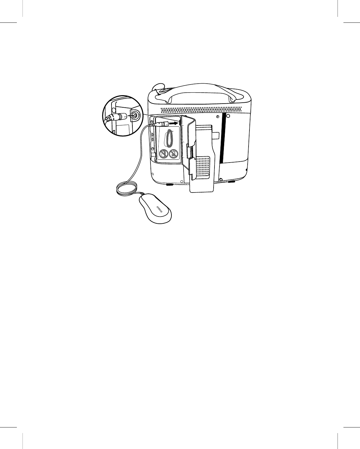
2.3.4 Connect the programming head
1. Open the door on the left rear of the programmer.
2. Line up the black arrows on the programming head cable and the programming head
connector.
3. Plug the cable into the programming head connector with the yellow marker.
4. Close the door, making sure the cable passes through the notch on the bottom of the
door.
Warning: Do not connect or disconnect the programming head while the programmer
power is on. Disconnecting the programming head causes an error that requires the
programmer to be shut down and restarted.
Printing instructions: doc#163256; refer to 'Reference manuals' row in the applicable table. 501346-089
Medtronic CARELINK ENCORE™ 29901
30 Reference Manual
M945141A001B Medtronic Confidential Composed: 2012-04-26 10:35:22
XSL-Stylesheet H - Reference manual 12-MAY-2011
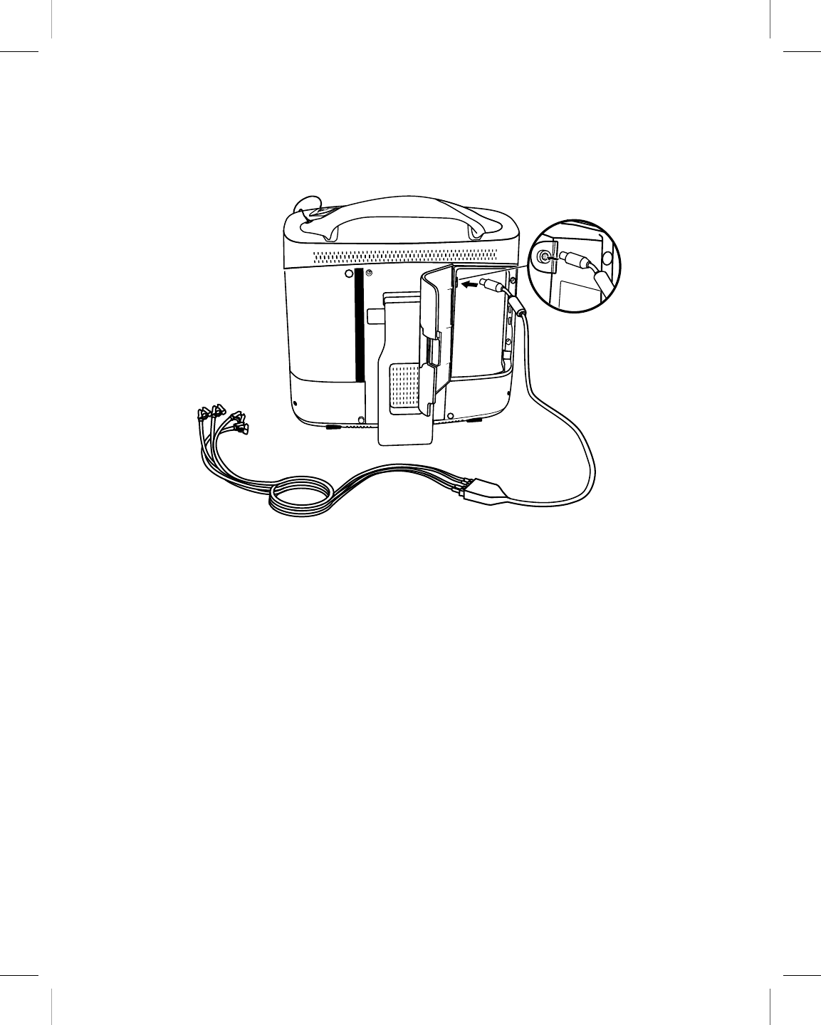
2.3.5 Connect the ECG cable
1. Open the right rear door.
2. Line up the ECG cable with the arrow next to the ECG connector.
3. Plug the cable into the connector.
4. Close the door, making sure that the cable passes through the notch on the lower left
side.
Note: Improper insertion of the ECG cable plug may damage the connector pins.
Printing instructions: doc#163256; refer to 'Reference manuals' row in the applicable table. 501346-089
Medtronic CARELINK ENCORE™ 29901
Reference Manual 31
M945141A001B Medtronic Confidential Composed: 2012-04-26 10:35:22
XSL-Stylesheet H - Reference manual 12-MAY-2011
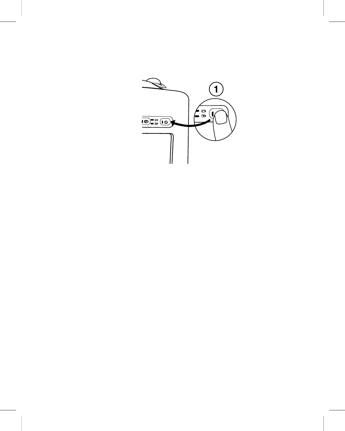
2.3.6 Turn on the programmer
1. Locate the Power button on the front right corner of the programmer button panel.
2. Press and release the Power button.
2.3.7 Troubleshoot potential interference
To address possible harmful interference between the programmer and other devices, you
are encouraged to take one or more of the following measures to address the situation:
●Reorient or relocate the devices.
●Increase the separation between the devices.
●Connect the equipment to an outlet on a different circuit.
●Consult Medtronic or Vitatron for help.
2.4 Charge the battery
2.4.1 About battery charge
When the programmer is connected to AC power, the battery automatically charges until it
reaches a full charge. Charging occurs when the unit is turned on, turned off or hibernating.
Typically an empty battery can be fully charged in two hours. A new, fully charged battery
operates for two hours (typical).
Printing instructions: doc#163256; refer to 'Reference manuals' row in the applicable table. 501346-089
Medtronic CARELINK ENCORE™ 29901
32 Reference Manual
M945141A001B Medtronic Confidential Composed: 2012-04-26 10:35:22
XSL-Stylesheet H - Reference manual 12-MAY-2011

Warning: Use the programmer for charging batteries, by installing the battery and
connecting the power supply. Unapproved charging equipment may damage the battery or
cause excessive heating, battery case rupture, or ignition of the battery cells. Use of a
damaged battery may damage equipment or cause user or patient injury.
2.4.2 Battery status indicators
There are two battery indicators on the programmer button panel that indicate the battery
status and the charging status, when active, as shown in Figure 6. The indication varies
depending on the operating condition (power state) of the programmer.
Figure 6. Battery indicators
1 Battery Status indicator
2 Battery Charge indicator
Table 2. Indicator color and indication
Indicator Indication
Battery Status indicator is solid amber The programmer is running on battery power,
battery power is 20% or less than the full charge,
and the programmer should plugged into AC
power to be recharged.
Battery Status indicator is flashing amber The programmer is running on battery power,
battery power is critically low, and the program-
mer needs to be plugged in to AC power imme-
diately to prevent shutdown.
Battery Charge indicator is solid green The programmer is running on AC power and the
battery has more than 90% of the full charge.
Battery Charge indicator is flashing green The programmer is running on AC power and the
battery has less than 90% of the full charge.
If the programmer is running on battery power and the battery power is getting low, the
Battery Power icon displays the power as yellow and a message displays a caution:
“Programmer battery is low. Connect the programmer to outlet power or continue at risk of
losing power. Estimating 20% or less programmer battery power remaining.”.
Printing instructions: doc#163256; refer to 'Reference manuals' row in the applicable table. 501346-089
Medtronic CARELINK ENCORE™ 29901
Reference Manual 33
M945141A001B Medtronic Confidential Composed: 2012-04-26 10:35:22
XSL-Stylesheet H - Reference manual 12-MAY-2011
If the programmer is running on battery power and battery power is critically low, the Battery
Power icon changed to a caution symbol and displays a warning: ”Critically low programmer
battery. Programmer will shut down. Plug in the programmer immediately to prevent shut
down.”. The programmer beeps once every 30 seconds and the Battery Power icon
bounces every 30 seconds for 9 seconds until it is replaced by another icon or you select
the warning.
Warning: If you receive a message on the programmer to replace the battery, you need to
replace the battery with a new battery. Use of a failed battery will reduce programmer
operating time and may cause user or patient injury.
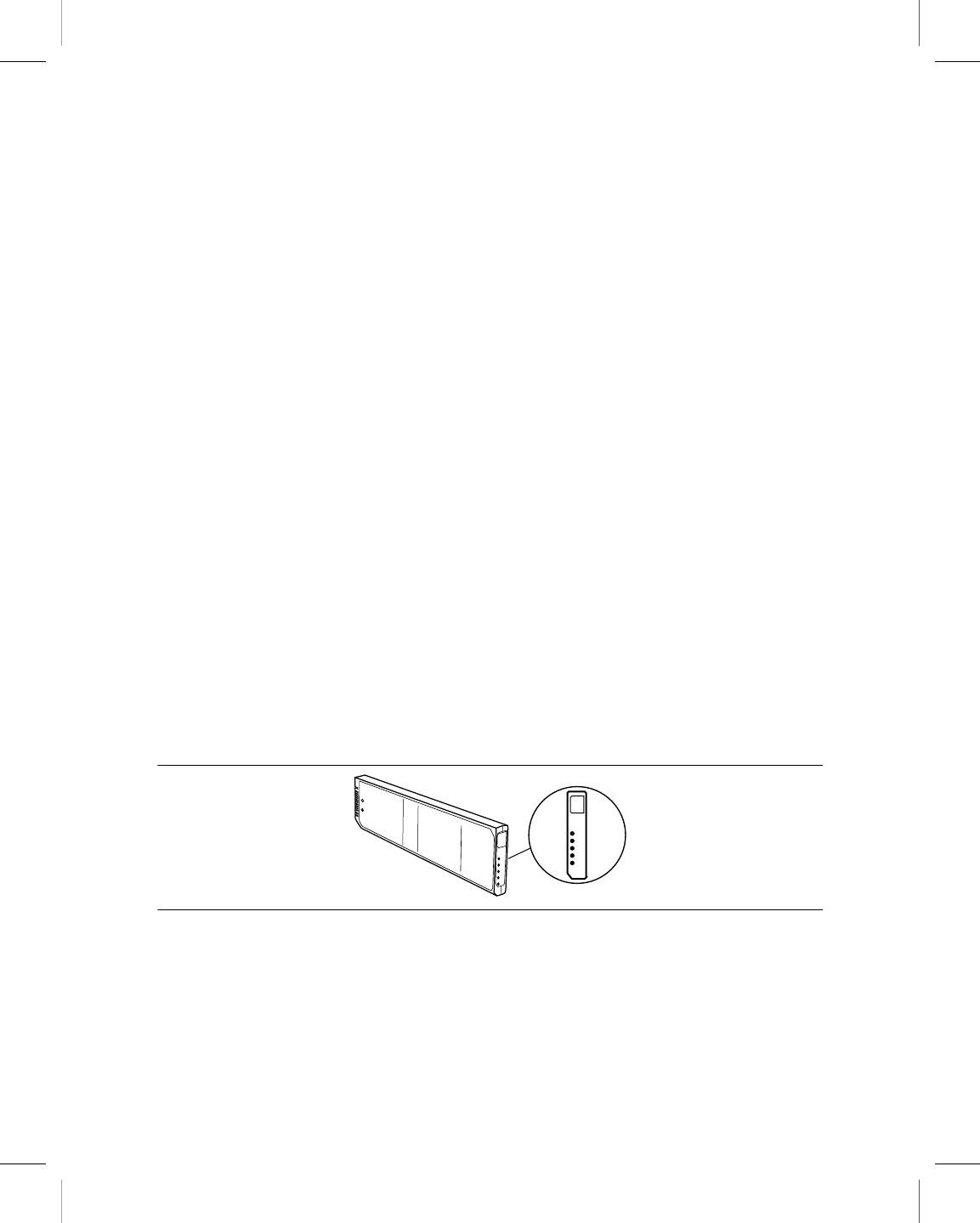
2.4.3 Battery pack indicators
In addition to the battery status indicators, the battery pack itself provides information about
the remaining charge and the charge capacity. By pressing the button on the front side of
the battery pack for less than 2 seconds, the indicator lights are lit displaying the remaining
charge:
●The first 4 lights each represent 20% of the total charge.
●The fifth light represents a minimum of 15% of the total charge
For example, if all 5 lights are lit, the remaining charge is more than 95% of the original/new
charge capacity. If only 2 lights are lit, the remaining charge is more than 40% but less than
60% of the original/new charge capacity.
By holding the button for more than 5 seconds until the lights start to flash, the indicator
lights display the indication of how the charge capacity has degraded with respect to the
original design capacity after an amount of time or number of charge cycles.
Figure 7. 80-100% of the original/new charge capacity
Printing instructions: doc#163256; refer to 'Reference manuals' row in the applicable table. 501346-089
Medtronic CARELINK ENCORE™ 29901
34 Reference Manual
M945141A001B Medtronic Confidential Composed: 2012-04-26 10:35:22
XSL-Stylesheet H - Reference manual 12-MAY-2011
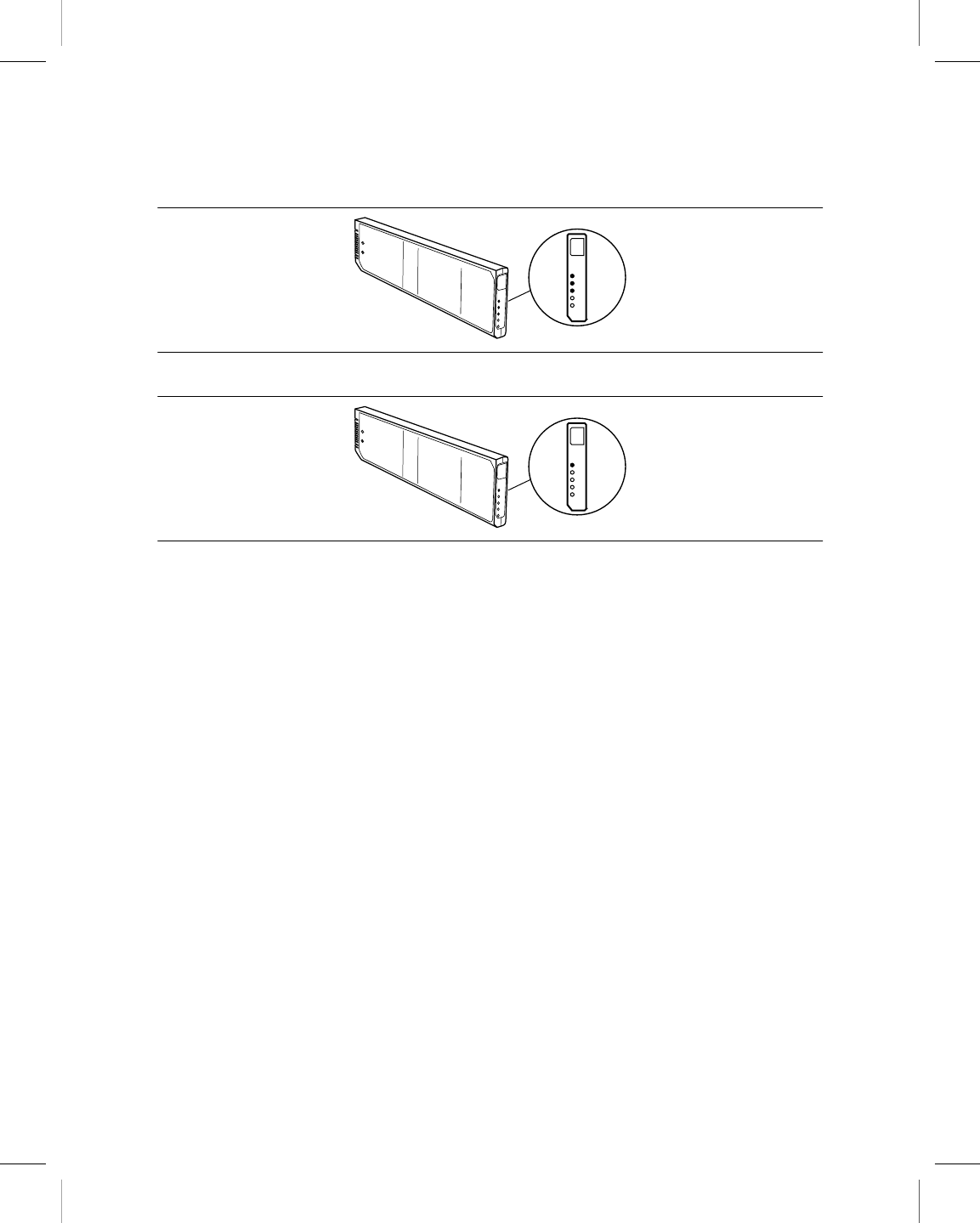
Figure 8. 60-79% of the original/new charge capacity
Figure 9. Less than 40% of the original/new charge capacity
Check the battery charge capacity periodically with the built-in indicator. Replace the battery
pack when the battery charge capacity is less than 60% of the original/new charge capacity,
and/or when the battery charge time increases significantly.
2.5 Use external printers
Connecting a compatible printer to the programmer allows you to print full, page-size reports
of session data when available. For more information, see the reference guide for the
implanted device. This section describes how to connect a printer to your programmer.
All printers listed by this software are certified to IEC 60950-1, UL 60950-1 or equivalent.
Only printers listed by this software may be connected to the programmer.
2.5.1 Printer compatibility
The programmer is compatible with many printers. A list of compatible printers can be
accessed from the Print Queue screen.
Note: When programming a Vitatron device, refer to the applicable Vitatron reference guide
for information about printing.
Printing instructions: doc#163256; refer to 'Reference manuals' row in the applicable table. 501346-089
Medtronic CARELINK ENCORE™ 29901
Reference Manual 35
M945141A001B Medtronic Confidential Composed: 2012-04-26 10:35:22
XSL-Stylesheet H - Reference manual 12-MAY-2011
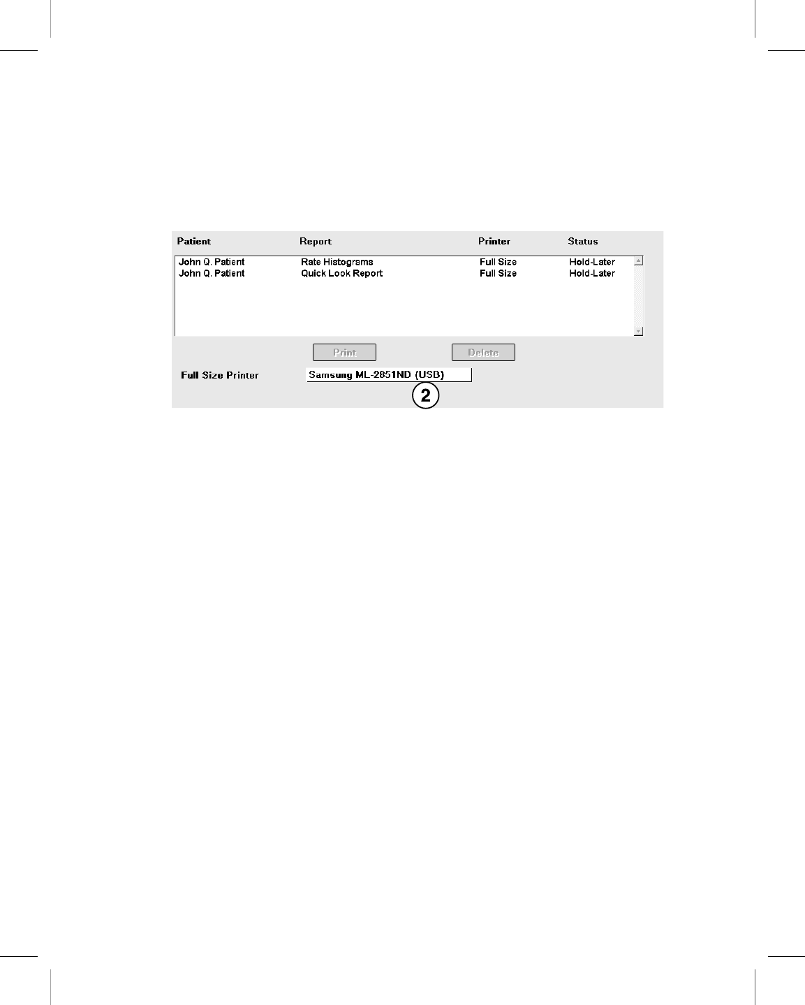
2.5.2 View a list of supported printers
1. If you are conducting a patient session, press the Reports icon, and then select
Print Queue.
If you are not conducting a patient session, press the Print Queue icon.
2. On the Print Queue screen, select the Printer field to open the list of supported printers.
2.5.3 Materials you need
To connect the programmer to a printer, you need either a Bluetooth printer or a USB printer
cable. One end of the USB cable must be a USB Type A connector. The other end of the
cable must fit the USB port on your printer.
2.5.4 Connect the printer
Note: The connection method you use depends on your printer.
Printing instructions: doc#163256; refer to 'Reference manuals' row in the applicable table. 501346-089
Medtronic CARELINK ENCORE™ 29901
36 Reference Manual
M945141A001B Medtronic Confidential Composed: 2012-04-26 10:35:22
XSL-Stylesheet H - Reference manual 12-MAY-2011
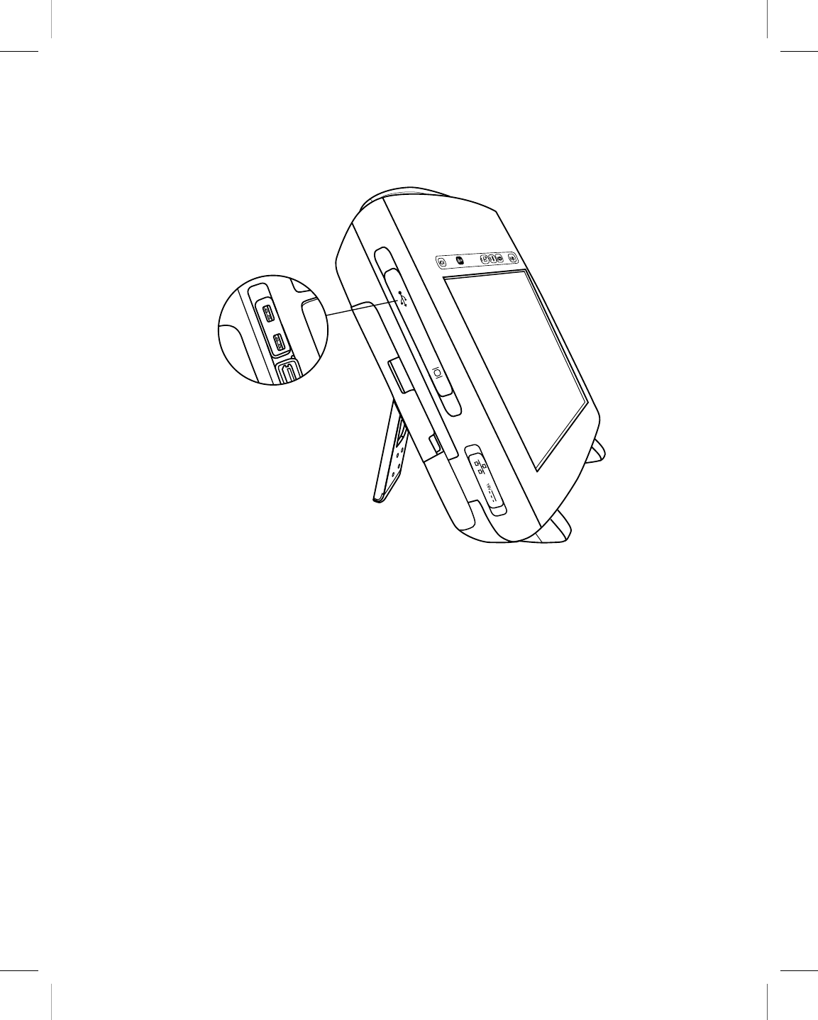
2.5.4.1 Connect to a printer with a USB cable
1. To connect to a printer with a USB cable, locate a USB port. There are two USB ports
located on the left front side of the programmer.
2. Open the input cover on the upper left side of the programmer.
3. Connect the printer cable to a USB port on the programmer.
4. Connect the other end of the cable to the printer. Connect the printer power cord to an
outlet and turn on the printer. Make sure that the printer has paper.
5. Turn on the programmer and select the Print Queue icon.
6. If not previously done, select the correct printer driver from the options listed when you
select the Printer field on the Print Queue window. You are now ready to use your
programmer with the connected printer.
Printing instructions: doc#163256; refer to 'Reference manuals' row in the applicable table. 501346-089
Medtronic CARELINK ENCORE™ 29901
Reference Manual 37
M945141A001B Medtronic Confidential Composed: 2012-04-26 10:35:22
XSL-Stylesheet H - Reference manual 12-MAY-2011

2.5.4.2 Connect to a printer with Bluetooth
1. To connect to a printer with Bluetooth, turn on the programmer and turn the Bluetooth
radio on for the programmer by pressing the Bluetooth button on the programmer
button panel.
2. Connect the printer power cord to an outlet and turn on the printer. Turn Bluetooth on
for the printer.
Note: For more information on turning on Bluetooth for the printer, refer to the printer
manual.
3. Launch the Bluetooth configuration application by pressing the Bluetooth icon on the
programmer taskbar.
4. Press [Search] to search for available Bluetooth printers. If the Bluetooth radio is
disabled on the programmer, a message is displayed that you need to enable the
Bluetooth radio on the programmer by pressing the Bluetooth button on the
programmer button panel.
5. The Pair Bluetooth Printer window is displayed listing the available Bluetooth
printers. Select the printer you would like to pair with the programmer.
Note: Only one printer can be paired with the programmer. To pair a new printer with
the programmer, you must unpair the currently paired printer.
6. Press [Pair]. Depending on your printer configuration, you will use one of the following
methods to pair to the printer:
●Enter the printer PIN on the programmer
●Enter the Passkey (PIN) on the printer
●Confirmation code sent to the printer
The programmer will automatically identify which method is needed to pair with a
specific printer.
a. To pair using a PIN, enter the PIN code found on the printer or in the printer manual.
The PIN can be between 1 and 16 characters. When you tap the PIN text field the
on-screen keyboard is displayed. Enter the PIN with the on-screen keyboard in the
Pair Bluetooth Printer window. After the PIN has been entered, press [OK].
Printing instructions: doc#163256; refer to 'Reference manuals' row in the applicable table. 501346-089
Medtronic CARELINK ENCORE™ 29901
38 Reference Manual
M945141A001B Medtronic Confidential Composed: 2012-04-26 10:35:22
XSL-Stylesheet H - Reference manual 12-MAY-2011

b. To pair using a passkey, enter the PIN from the Pair Bluetooth Printer window
on your printer. The dialog automatically closes if the passkey is entered correctly.
Note: The passkey is referred to as a “PIN”, but it is different from the PIN supplied
by the printer and entered on the programmer.
c. To pair using a confirmation code, the programmer generates a code and sends it
to the printer. The Pair Bluetooth Printer window displays the confirmation code.
Confirm that the correct code was sent to the printer and press [Yes].
7. The Pair Bluetooth Printer window shows a pairing activity indicator. When pairing
has completed successfully, the Configure Bluetooth window confirms that the
printer you selected is currently paired.
8. Select the Print Queue icon.
Note: Be sure to select the correct printer driver from the options listed when you select
the Printer field on the Print Queue window. Make sure that the printer has paper. You
are now ready to use your programmer with the paired printer.
Printing instructions: doc#163256; refer to 'Reference manuals' row in the applicable table. 501346-089
Medtronic CARELINK ENCORE™ 29901
Reference Manual 39
M945141A001B Medtronic Confidential Composed: 2012-04-26 10:35:22
XSL-Stylesheet H - Reference manual 12-MAY-2011
3 Configure the programmer
3.1 Display screen features
The programmer display screen is a touch-sensitive interface that displays text and
graphics. It is also a control panel that displays buttons and menu options that you can
select.
3.1.1 Features and conventions of the display screen
This section provides an overview of the features of the display screen. For more
information, see the reference guide for the implanted device. The main elements of a typical
display screen before you select a model, when you turn the programmer on, and when you
end a patient session, are shown in Figure 10.
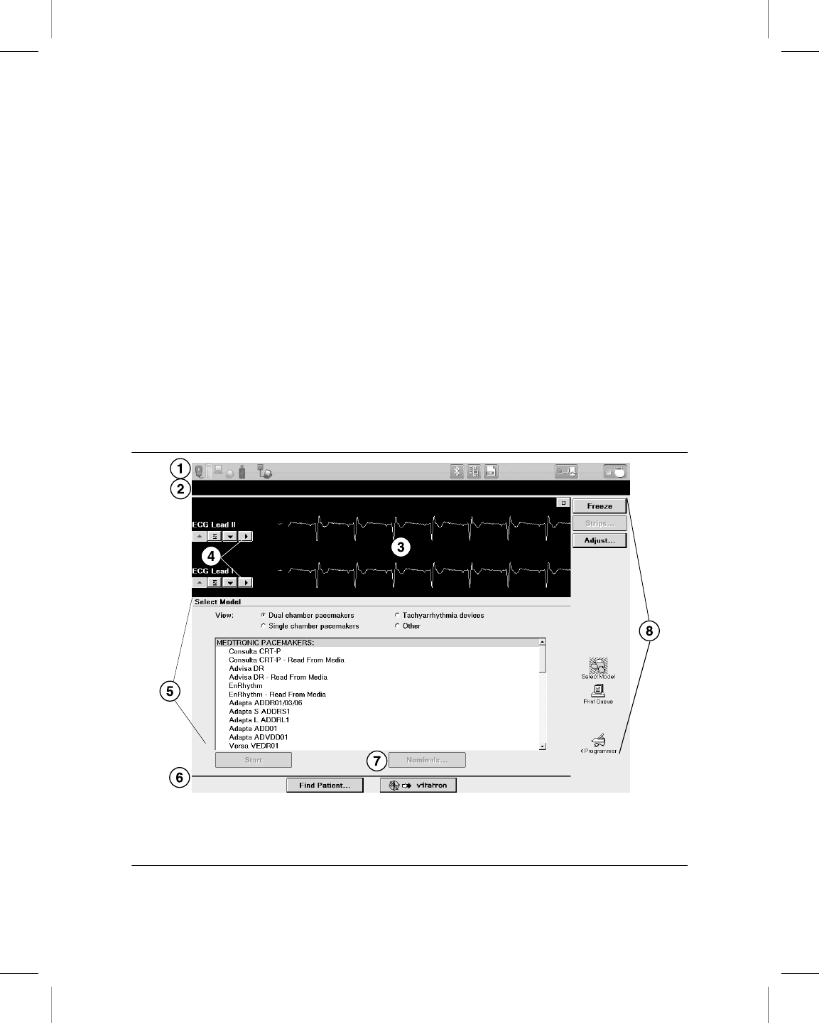
Figure 10. Main elements of the display screen
1 Task bar
2 Status bar
3 Live Rhythm Monitor window
4 Waveform adjustment bars
5 Task area
6 Command bar
7 Buttons
8 Tool palette
Printing instructions: doc#163256; refer to 'Reference manuals' row in the applicable table. 501346-089
Medtronic CARELINK ENCORE™ 29901
40 Reference Manual
M945141A001B Medtronic Confidential Composed: 2012-04-26 10:35:22
XSL-Stylesheet H - Reference manual 12-MAY-2011
Vitatron display screens may be different. For more information, see the reference guide
for the implanted device. If you see a Medtronic/Vitatron switch button, press it to display
the Vitatron Select Model screen.
3.1.1.1 Task bar
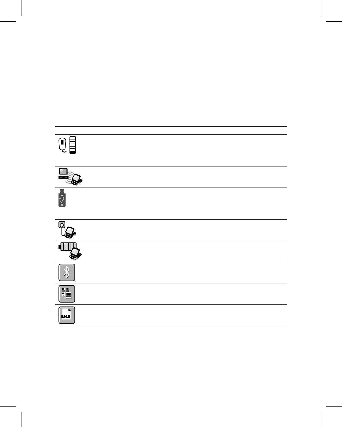
The task bar can contain these icons/indicators:
Table 3. Task bar icons/indicators
Icon Name Function
Telemetry strength Turns green to indicate successful communication
between the programming head and the device. More
green bars on the array indicates better communication. A
minimum of two green bars should be lit. An amber light
means the device is out of range.
SessionSync Provides information about the connection and data trans-
fer status between the Programmer and the data manage-
ment system. SessionSync is an optional feature.
External USB drive Turns green to indicate a USB flash drive or other external
storage media are available for saving PDF reports and
patient data. When inserting a USB flash drive, you may
experience a slight delay before the device is available for
use.
AC Power Appears in the taskbar to indicate that the programmer is
connected to AC power.
Battery Power Provides information about the status of the battery power
when the programmer is not connected to AC power.
Bluetooth configuration Opens the Configure Bluetooth window for connecting a
Bluetooth-enabled printer to the programmer.
Network Configuration Opens the Network Configuration window for configuring
network preferences.
PDF Viewer Used to view PDFs from a USB flash drive. PDFs can be
viewed while in a device application or on the programmer
desktop.
Printing instructions: doc#163256; refer to 'Reference manuals' row in the applicable table. 501346-089
Medtronic CARELINK ENCORE™ 29901
Reference Manual 41
M945141A001B Medtronic Confidential Composed: 2012-04-26 10:35:22
XSL-Stylesheet H - Reference manual 12-MAY-2011
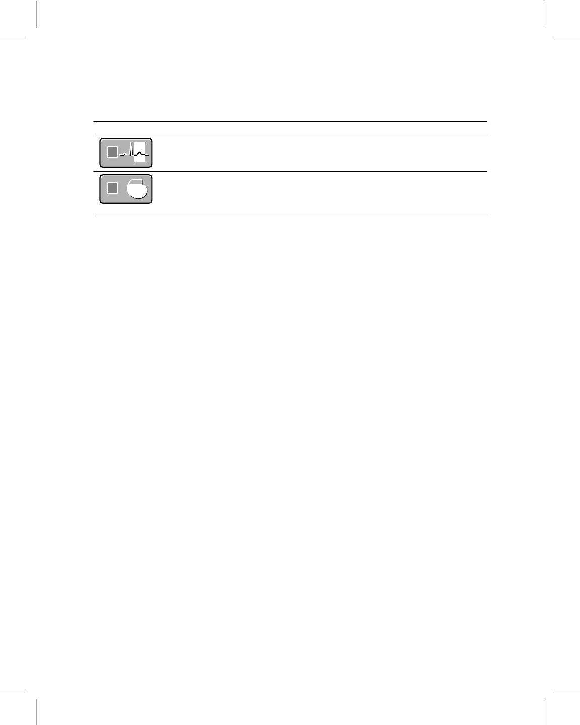
Table 3. Task bar icons/indicators (continued)
Icon Name Function
Electronic Strip Chart
(eStrip) selector
Used to go to the Electronic Strip Chart (eStrip) recorder
screen.
Device Application
selector
Used to go to the Select Model screen on the programmer
desktop. During a patient session, the indicator box turns
blue to indicate that the programmer is on a device appli-
cation screen.
3.1.1.2 Status bar
Before selecting a model, the status bar has no information. For specific information about
the status bar, refer to the reference guide for the implanted device. After model selection,
the status bar may include:
●The present pacing mode.
●Test condition status.
●The device model.
3.1.1.3 Live Rhythm Monitor window
This window is a partial view of the full-screen display of the ECG, and contains a Waveform
adjustment bar that allows you to change the size of the waveform. You can expand this
window to full size by selecting the small square button in the upper-right corner of the
window or by pressing [Adjust…].
After model selection, Marker Channel and telemetered EGM waveform traces may be
available.
3.1.1.4 Task area
The portion of the screen between the Live Rhythm Monitor window near the top of the
screen and the command bar at the bottom of the screen changes according to the task or
function you select.
3.1.1.5 Command bar
The bar at the bottom of the screen shows the command buttons for automatically launching
the proper software application and displaying the Vitatron Select Model screen. For
information on what command buttons are available after selecting a model, see the
reference guide for the implanted device.
Printing instructions: doc#163256; refer to 'Reference manuals' row in the applicable table. 501346-089
Medtronic CARELINK ENCORE™ 29901
42 Reference Manual
M945141A001B Medtronic Confidential Composed: 2012-04-26 10:35:22
XSL-Stylesheet H - Reference manual 12-MAY-2011
3.1.1.6 Buttons
Buttons allow you to operate the programmer. You can “press” a button by touching it with
the tip of the stylus or your finger.
Buttons may directly execute a command, such as [Freeze], or they may open a window
that prompts another action. Buttons that open a window usually have a label ending with
an ellipsis, such as [Strips…] or [Adjust…].
A procedure may instruct you to “press and hold” a button. Press the button and maintain
pressure until it is time to “release” the button.
When a button is inactive, it appears a lighter color and does not execute a command when
you press it.
3.1.1.7 Tool palette
The collection of buttons and icons along the edge of the screen is referred to as the “tool
palette”. These buttons and icons are the controls you use to choose the task or function
screen you want to display. Each of the icons acts like a button. Touch the icon to select it.
For more information, see Section 3.2. For information about the session tool palette, see
the reference guide for the implanted device.
3.2 About the Between Patient Sessions tool palette
The Between Patient Sessions tool palette is on the Select Model screen. The Select Model
screen appears before you select a model, when you turn the programmer on, and when
you end a patient session.
The tools that are available between patient sessions are described in Table 4.
Note: When programming a Vitatron device, refer to the applicable reference guide for
information about the tool palette.
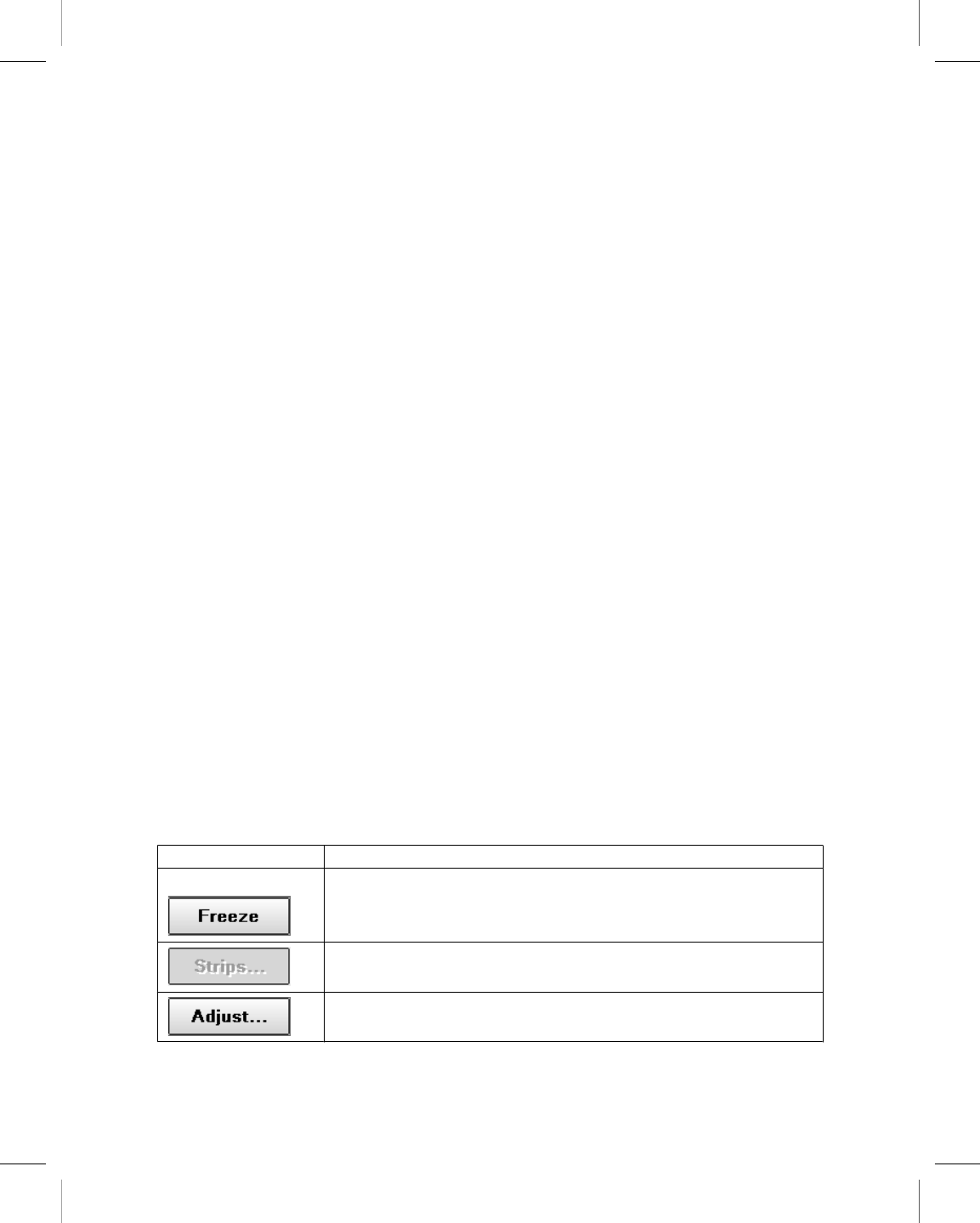
Table 4. Between Patient Sessions tool palette
Tool Selecting the tool (button or icon)…
Freezes a segment of the live rhythm display.
Note: A frozen strip can be viewed, printed, or saved to PDF between
patient sessions. Markers and EGM traces are not present between
patient sessions.
The [Strips…] button is not available between patient sessions. Saved
rhythm strips can only be accessed during a patient session.
Opens a window of options for adjusting the live rhythm display.
Note: Additional adjustment options are present during a patient session.
Printing instructions: doc#163256; refer to 'Reference manuals' row in the applicable table. 501346-089
Medtronic CARELINK ENCORE™ 29901
Reference Manual 43
M945141A001B Medtronic Confidential Composed: 2012-04-26 10:35:22
XSL-Stylesheet H - Reference manual 12-MAY-2011
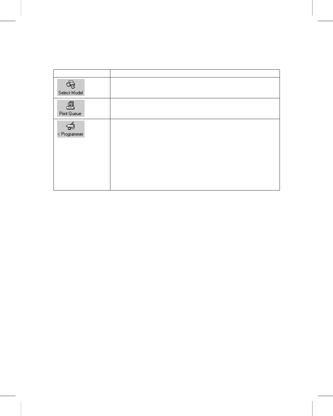
Table 4. Between Patient Sessions tool palette (continued)
Tool Selecting the tool (button or icon)…
Displays the screen for selecting a model and starting a patient session.
Displays a queue of print requests from previous sessions as well as frozen
waveform reports requested between sessions. Refer to the reference
guide for the implanted device to determine if these features are available.
Displays the programmer setup options.
Preferences
Time and Date
Artifact Detection
Software
Demonstrations
Programmer Profile
SessionSync Status
SessionSync Network Configuration…
Other Software
Tools
Licensing
Note: When some functions are active on the display, pressing a tool button or icon has no
effect. Closing the active window restores operation of the tool palette.
3.3 Change the language setting
The software is translated into several languages. Use the following procedure to determine
which languages are available. For Vitatron devices, see the applicable reference guide.
3.3.1 Choose a language
1. Press the Programmer icon, and then select Preferences.
2. From the Preferences screen, select the Language field to display the options.
Note: The programmer screen goes blank for about 2 minutes after selecting a language.
The programmer then resumes operation in the selected language.
Printing instructions: doc#163256; refer to 'Reference manuals' row in the applicable table. 501346-089
Medtronic CARELINK ENCORE™ 29901
44 Reference Manual
M945141A001B Medtronic Confidential Composed: 2012-04-26 10:35:22
XSL-Stylesheet H - Reference manual 12-MAY-2011

3.4 Use the on-screen keyboard
The on-screen keyboard is used for entering text into an editable field. When you tap in an
editable field, the on-screen keyboard displays. When you tap outside the editable field, the
on-screen keyboard stops displaying. For fields that have frequently re-used names, terms
or medical terminology, a selectable library displays when the field is selected. The library
provides you with the ability to add or reuse words when entering text.
3.5 View and update programmer location and
hardware information
Information about the location of the programmer and its hardware is on the Programmer
Profile screens.
The Programmer Profile location screen has the following information:
●Clinic’s name, address, telephone number, contact person, and customer account
number
●Service representative’s name, telephone number, fax number, and e-mail address
The Programmer Profile hardware screen has the model and serial numbers for the
programmer. You can also enter the model and serial numbers for the programming head.
Information on the screen may be updated by selecting the appropriate field and then using
the keyboard.
3.5.1 Verify Programmer Profile information
Each programmer has a profile screen that contains identifying information about the
installed hardware, the programmer location, and contact information for the Medtronic
service representative.
Typically, the profile is completed when the programmer is first installed, and then updated
only when necessary.
1. Press the Programmer icon, and then select Programmer Profile. Location
Information appears by default.
2. Complete the location information or verify that the information shown is correct.
3. To view hardware information, select Hardware Information.
Printing instructions: doc#163256; refer to 'Reference manuals' row in the applicable table. 501346-089
Medtronic CARELINK ENCORE™ 29901
Reference Manual 45
M945141A001B Medtronic Confidential Composed: 2012-04-26 10:35:22
XSL-Stylesheet H - Reference manual 12-MAY-2011
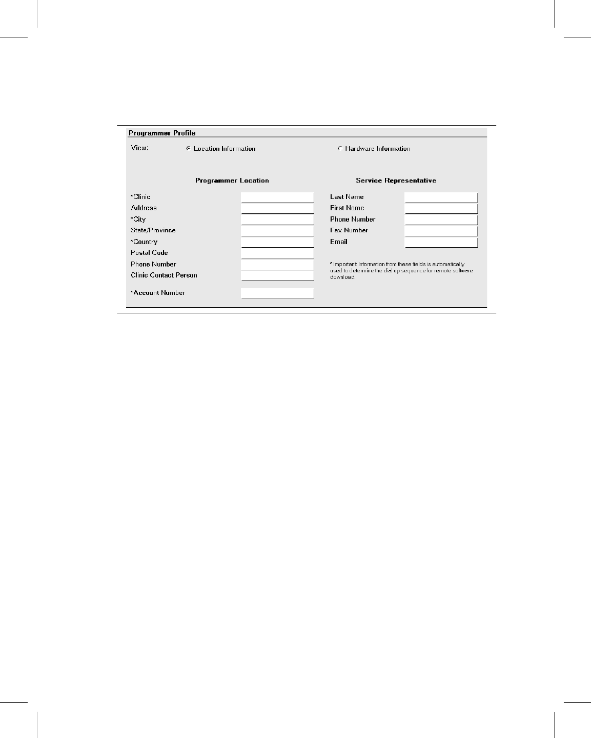
Figure 11. Programmer Profile screen
3.6 Adjust programmer time and date
If the time or date displayed and printed by the programmer is incorrect, use the following
procedure to enter the correct settings. For Vitatron devices, see the applicable reference
guide.
3.6.1 Set the time and date
1. Press the Programmer icon then Time and Date.
2. From the Programmer Time and Date screen, press the up or down button to increase
or decrease the value for the unit of time you want to change. Press and release the
button for single unit changes or press and hold the button to effect greater changes.
3. When all fields show the correct time and date, press [Apply]. Select another tool
palette icon to close the Programmer Time and Date window
Printing instructions: doc#163256; refer to 'Reference manuals' row in the applicable table. 501346-089
Medtronic CARELINK ENCORE™ 29901
46 Reference Manual
M945141A001B Medtronic Confidential Composed: 2012-04-26 10:35:22
XSL-Stylesheet H - Reference manual 12-MAY-2011
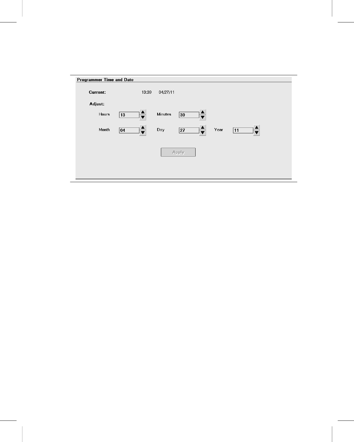
Figure 12. Programmer Time and Date screen
Note: Time must be entered based on a 24-hour clock, with 00:00 being midnight, and
12:00 being noon.
3.7 Select audible tones
Certain events in the operation of the programmer result in an audible signal. The following
tones alert you to the success or failure of an action.
●A two-tone beep (low-to-high) indicates confirmation of an Interrogate or a Program
command.
●A double low-tone beep indicates that an Interrogate, Program, or Emergency
command was not confirmed. It can also indicate that the selected command cannot
be executed.
Note: For some devices, the tones may not be turned off. For more information, see the
reference guide for the implanted device. For Vitatron devices, see the applicable reference
guide.
3.7.1 Turn tones on or off
1. Press the Programmer icon, and then select Preferences.
2. From the Preferences screen, select [Audio ON] or [Audio OFF] as desired.
Printing instructions: doc#163256; refer to 'Reference manuals' row in the applicable table. 501346-089
Medtronic CARELINK ENCORE™ 29901
Reference Manual 47
M945141A001B Medtronic Confidential Composed: 2012-04-26 10:35:22
XSL-Stylesheet H - Reference manual 12-MAY-2011
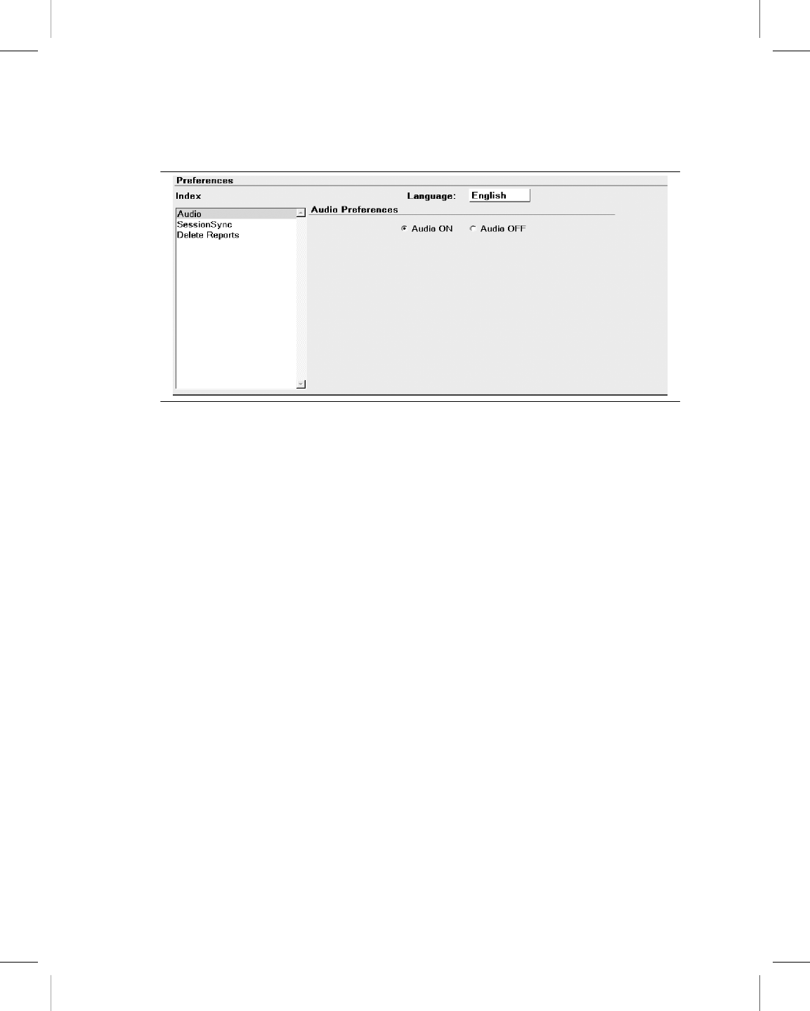
Figure 13. Audio Preferences screen
3.8 Check the software version
This section describes how to determine the version of software that is loaded on the
programmer.
If you need to know what version of software is currently loaded on the programmer for any
of the device models, use the following procedure.
For Vitatron devices, see the applicable reference guide.
3.8.1 To check the software version number
1. Select Programmer, and then select Software.
2. For each device model with software loaded on the programmer, the screen displays
the software version number next to the model number.
Printing instructions: doc#163256; refer to 'Reference manuals' row in the applicable table. 501346-089
Medtronic CARELINK ENCORE™ 29901
48 Reference Manual
M945141A001B Medtronic Confidential Composed: 2012-04-26 10:35:22
XSL-Stylesheet H - Reference manual 12-MAY-2011
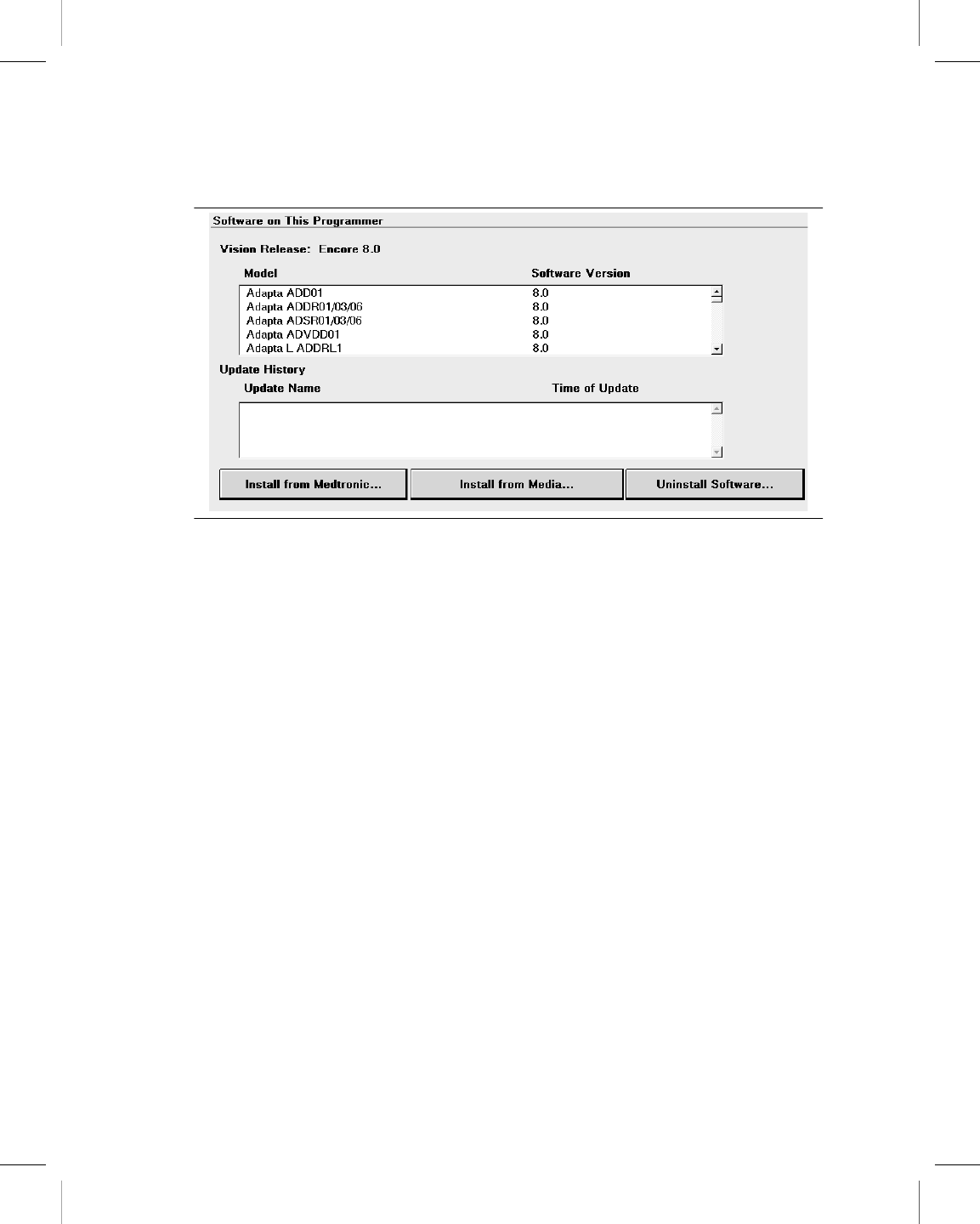
Figure 14. Software on This Programmer screen
Note: If the model that you require is not displayed, the software to support that model is
not currently loaded on the programmer. Contact your Medtronic or Vitatron representative.
3.9 Select other software
In addition to the standard application software, there are some programmers that have
other applications installed. These applications may include supplemental software or
software used in clinical studies for research. If you have other software installed, you may
access the software, using the following procedure.
1. Press the Programmer icon, and then select Other Software.
2. When the programmer displays the list of available software, select the application and
press [Start].
3.10 Remove other software applications
Programmers with other software installed, such as supplemental software or those used
in clinical studies for research, may allow the applications to be removed from the
programmer desktop. If you have software installed that permits removal, you may remove
it using the following procedure.
1. Press the Programmer icon, and then select Software.
2. Press [Uninstall Software…].
Printing instructions: doc#163256; refer to 'Reference manuals' row in the applicable table. 501346-089
Medtronic CARELINK ENCORE™ 29901
Reference Manual 49
M945141A001B Medtronic Confidential Composed: 2012-04-26 10:35:22
XSL-Stylesheet H - Reference manual 12-MAY-2011

3. When the programmer displays the list of removable software, select the application
to be removed, and then press [Uninstall].
4. Select the check box next to the acknowledgment statement, and then press
[Continue].
5. The software is removed, and the programmer reboots.
6. Verify that the software has been removed.
3.11 Improve the detection of pacing artifacts
The Artifact Detection function allows you to improve the detection of pacing artifacts when
interference causes either false artifacts or no artifacts to appear on the patient’s ECG.
Pacing artifacts are displayed on the patient’s ECG when the artifact detection option (Show
Artifacts) has been enabled.
To determine if this feature is applicable, see the reference guide for the implanted device.
3.11.1 Enable artifact detection
1. Press the Programmer icon, and then select Artifact Detection.
2. Make sure the current settings include ARTIFACT DISPLAY IS ON.
3. Make sure the current settings include MV FILTER IS ON.
3.12 Start the Demonstrations option
The demonstrations option allows you to run a demonstration program on the programmer.
For Vitatron devices, see the applicable reference guide.
Note: Device applications and reference manuals may still refer to using the “demonstration
disk” or “demonstration diskette” to run a demonstration program. The need for a
demonstration diskette to access demonstration mode is no longer required. All references
to a demonstration diskette can be ignored. All demonstration mode features are accessible
with or without a demonstration diskette.
Printing instructions: doc#163256; refer to 'Reference manuals' row in the applicable table. 501346-089
Medtronic CARELINK ENCORE™ 29901
50 Reference Manual
M945141A001B Medtronic Confidential Composed: 2012-04-26 10:35:22
XSL-Stylesheet H - Reference manual 12-MAY-2011
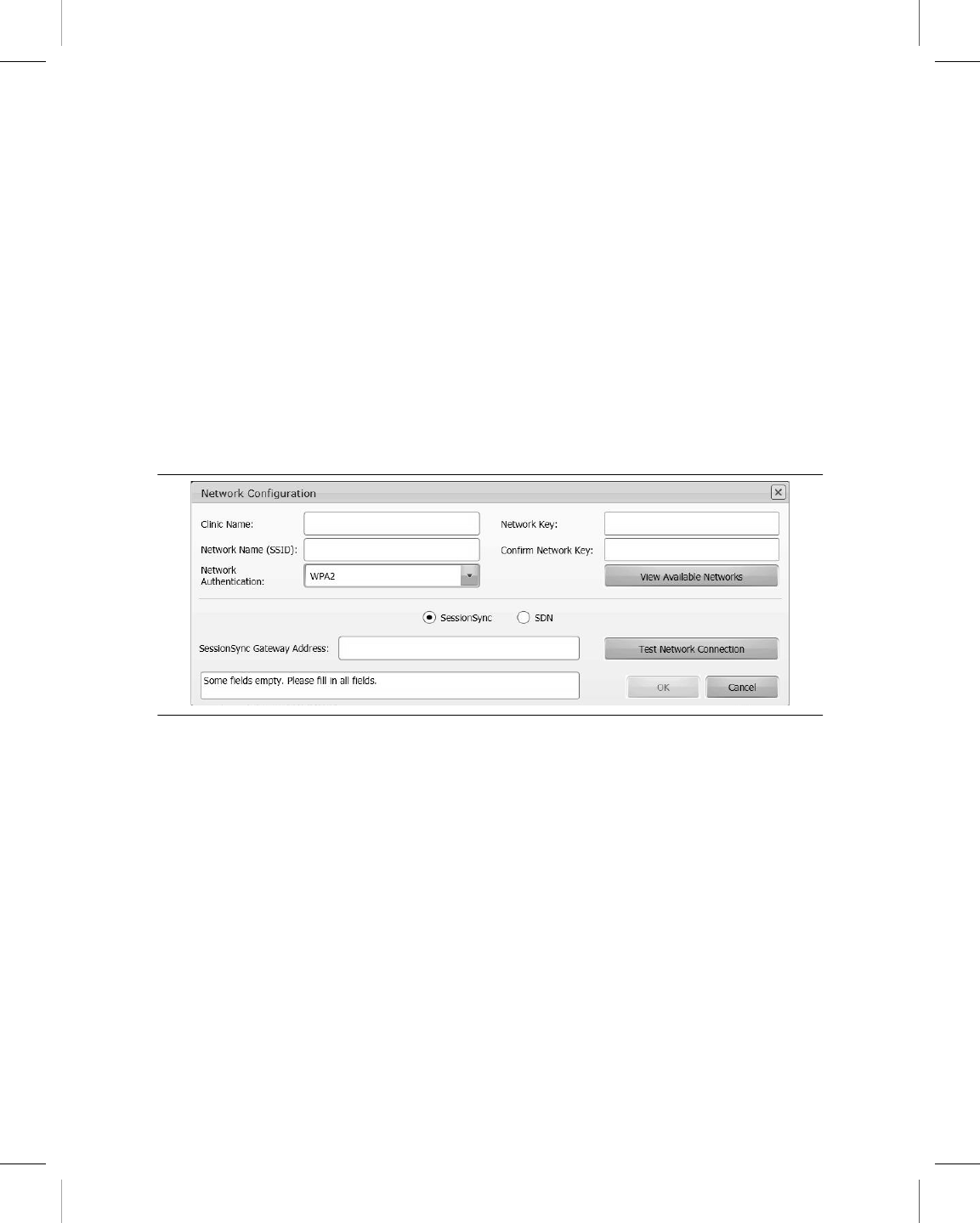
3.12.1 Access demonstrations
1. Press the Programmer icon, and then select Demonstrations.
2. From the Demonstration Model Selection screen, select the desired View option to list
the available demonstration programs.
3. Select the desired demonstration program and press [Start] followed by [Continue].
3.13 Configure network using the Network Configuration
window
3.13.1 About the Network Configuration window
Figure 15. Network Configuration window
The Network Configuration window is used to set up connections to the Software
Distribution Network (SDN) and SessionSync using wireless and Ethernet conections. The
first time the Network Configuration window is accessed the Clinic Name field is empty. For
SessionSync, the SessionSync Gateway Address field also needs to be filled in. Until the
Clinic Name and SessionSync Gateway Address fields are filled in, the [OK] is disabled.
After you click [OK], the values are saved and the dialog closes. The next time the dialog is
opened, the fields will be populated with the previously saved values and the [OK] will be
enabled. If you manually clear one or more fields, the [OK] is disabled and the “Some fields
empty…“ message is displayed in the entry error text box.
Printing instructions: doc#163256; refer to 'Reference manuals' row in the applicable table. 501346-089
Medtronic CARELINK ENCORE™ 29901
Reference Manual 51
M945141A001B Medtronic Confidential Composed: 2012-04-26 10:35:22
XSL-Stylesheet H - Reference manual 12-MAY-2011

3.13.2 Configure network connection
1. Press the Network Configuration icon on the task bar. The programmer displays the
Network Configuration window.
2. Select the radio button for SDN or SessionSync.
Note: If you selected SessionSync, you also need to enter the SessionSync Gateway
Address. The field is visible only after selecting SessionSync.
3. Enter the Clinic Name.
4. Enter the Network Name (SSID). To select the Network Name from the Available
Networks, see Section 3.13.3.
5. Select Network Authentication from the drop-down list.
6. Enter Network Key.
7. Re-enter the Network Key in the Confirm Network Key field.
8. Press [OK].
3.13.3 View available networks
Note: Wi-Fi must be enabled to view available networks. Press the Wi-Fi button to enable
Wi-Fi. If there is an Ethernet connection when the Network Configuration window is
launched, a Wi-Fi connection cannot be established.
1. Press [View Available Networks]. The View Available Networks dialog displays with
no network selected and the [OK] button disabled. When you select a network, the
[OK] button is enabled.
Note: If there are no available networks, the View Available Networks dialog will not
have any networks listed. If there are more than 3 available networks, the first three
are visible and a vertical scroll bar is displayed.
2. After you select the network and press the [OK] button, the Network Name (SSID) field
displays the network you selected in the Network Configuration dialog.
3.13.4 Test the network connection
After connecting to the network, you can test the connection to make sure the programmer
is connected properly. From the Network Configuration window, press [Test Network
Connection]. The Test Output: field displays the results of the test and is scrollable using
the up and down arrows on the right.
Printing instructions: doc#163256; refer to 'Reference manuals' row in the applicable table. 501346-089
Medtronic CARELINK ENCORE™ 29901
52 Reference Manual
M945141A001B Medtronic Confidential Composed: 2012-04-26 10:35:22
XSL-Stylesheet H - Reference manual 12-MAY-2011

Use the Test Network Connection feature if your programmer is having difficulty connecting
to your clinic’s network. Contact Medtronic Technical Support if you need assistance in
interpreting results.
3.13.5 Save network connection test results to media
1. Connect a USB flash drive to the programmer.
2. Press [Save To Media].
Note: This button is available only if the Test Network Connection tests have been run.
The programmer displays the Save to Media dialog.
3. Press [Save].
A text file (NtwkTestOutput.log) containing the test results is saved to the USB flash drive.
Download the file to a compatible computer for viewing and/or transfer to Medtronic
personnel.
Printing instructions: doc#163256; refer to 'Reference manuals' row in the applicable table. 501346-089
Medtronic CARELINK ENCORE™ 29901
Reference Manual 53
M945141A001B Medtronic Confidential Composed: 2012-04-26 10:35:22
XSL-Stylesheet H - Reference manual 12-MAY-2011

4 Update programmer software using the
Software Distribution Network
4.1 The Software Distribution Network
Programmer software can be updated by Medtronic customers or Medtronic personnel by
accessing the Medtronic Software Distribution Network (SDN) and downloading the
software. The SDN uses a world-wide network to connect to servers in the United States.
These servers are able to download software to many programmers simultaneously through
secure connections.
The SDN is available 24 hours per day, 7 days per week and always contains the most
current software. For this reason, it is recommended that you download the software from
the SDN rather than from the flash drive. You can connect to the SDN using a wired or
wireless network connection.
Notes:
●It is recommended that the SDN be checked on a regular basis. Checking regularly
reduces the size of the download and the time it takes to receive the software.
●If the download was interrupted, the download will resume the next time the programmer
attempts to access the SDN.
●Normal programmer functions are unavailable during software installation.
4.2 Connect to the SDN using a wired network connection
You can connect to the SDN using the Integrated Ethernet connection and your clinic’s
network. By connecting through your network, software download time can be reduced.
Before you begin, make sure that the Ethernet cable is correctly connected to the Integrated
Ethernet connection.
Printing instructions: doc#163256; refer to 'Reference manuals' row in the applicable table. 501346-089
Medtronic CARELINK ENCORE™ 29901
54 Reference Manual
M945141A001B Medtronic Confidential Composed: 2012-04-26 10:35:22
XSL-Stylesheet H - Reference manual 12-MAY-2011
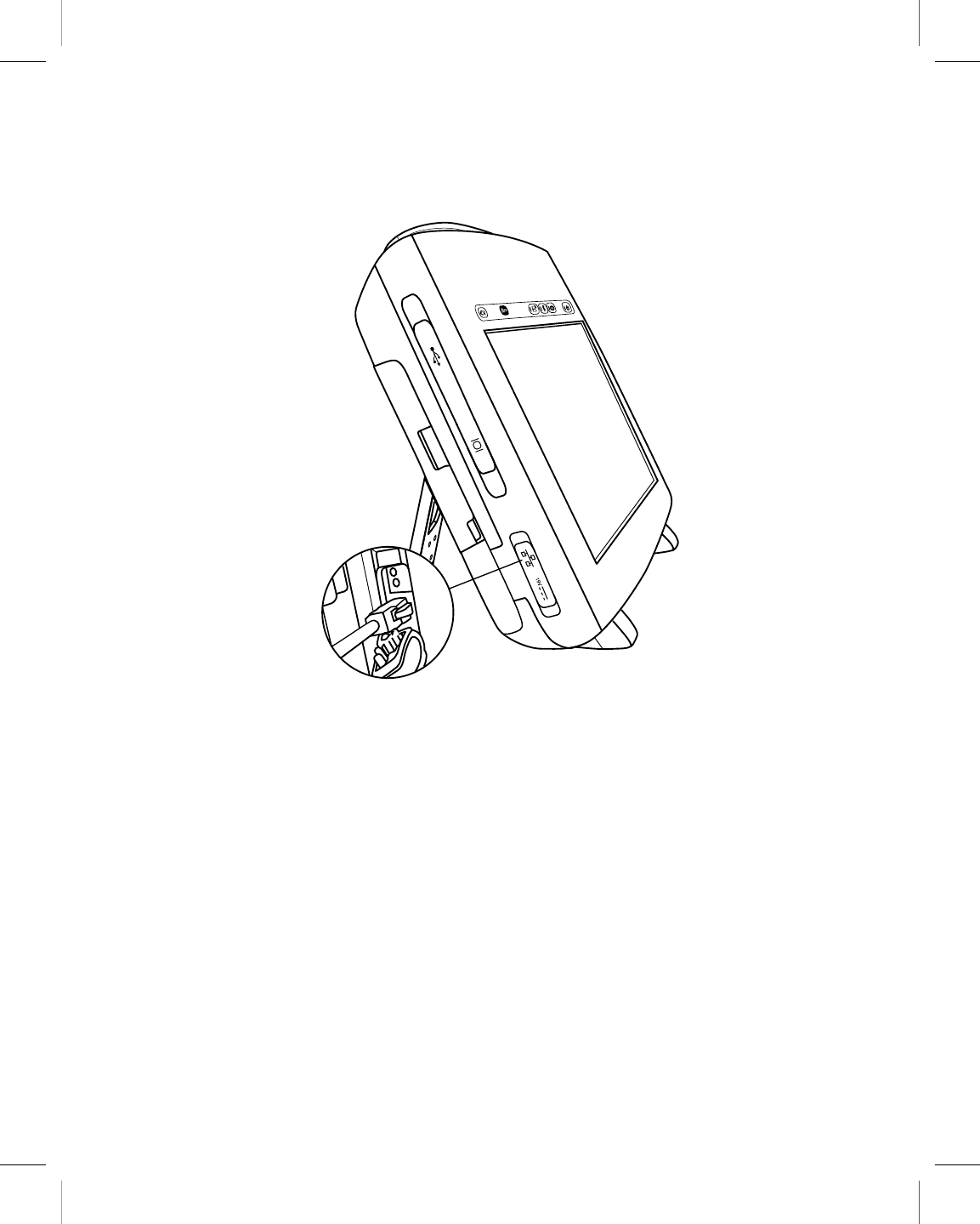
4.2.1 Connect the Ethernet cable
1. Open the input cover on the lower left side of the programmer.
2. Connect the Ethernet cable to the Integrated Ethernet connection.
3. Connect the opposite end of the Ethernet cable to a network jack.
Printing instructions: doc#163256; refer to 'Reference manuals' row in the applicable table. 501346-089
Medtronic CARELINK ENCORE™ 29901
Reference Manual 55
M945141A001B Medtronic Confidential Composed: 2012-04-26 10:35:22
XSL-Stylesheet H - Reference manual 12-MAY-2011
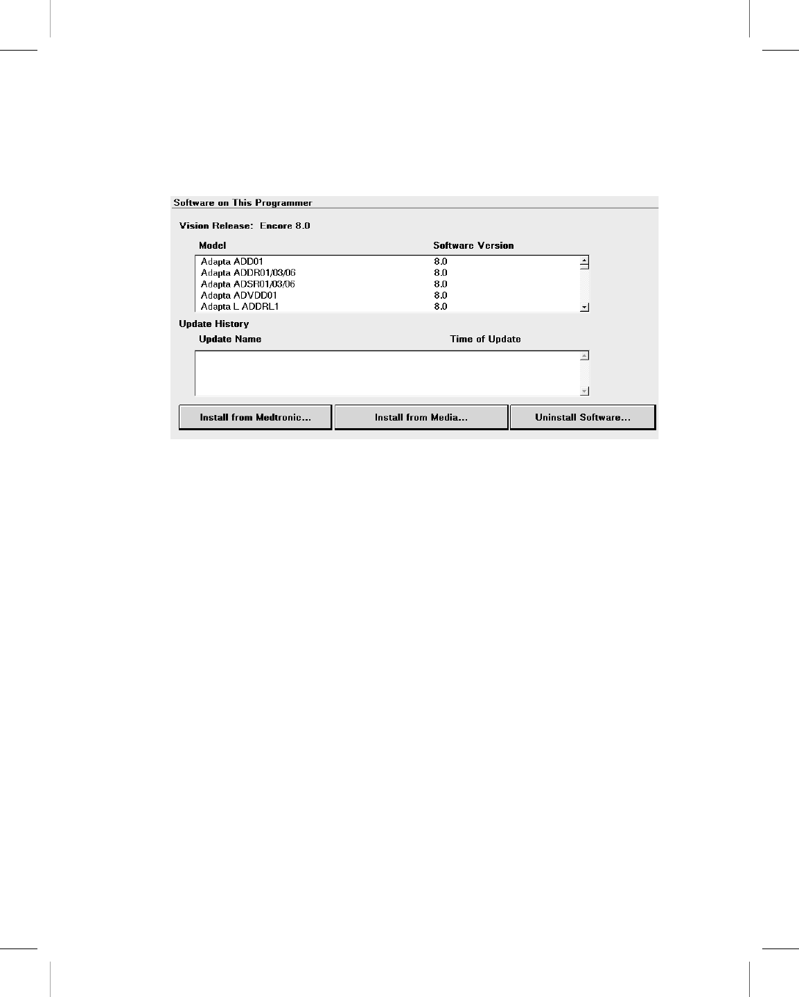
4.2.2 How to connect to the SDN using a wired network connection
1. Press the Programmer icon, and then select Software.
The programmer displays the Software on This Programmer screen and lists the
software already installed on the programmer. For each model, the screen displays
the software version.
Note: The SDN cannot be accessed from Vitatron screens. Change to the Medtronic
Select Model screen.
2. Press [Install from Medtronic…].
3. Follow the prompts that are displayed to start the download.
or
Press [Cancel]. The download process is canceled and the programmer redisplays the
Software on This Programmer screen.
Printing instructions: doc#163256; refer to 'Reference manuals' row in the applicable table. 501346-089
Medtronic CARELINK ENCORE™ 29901
56 Reference Manual
M945141A001B Medtronic Confidential Composed: 2012-04-26 10:35:22
XSL-Stylesheet H - Reference manual 12-MAY-2011
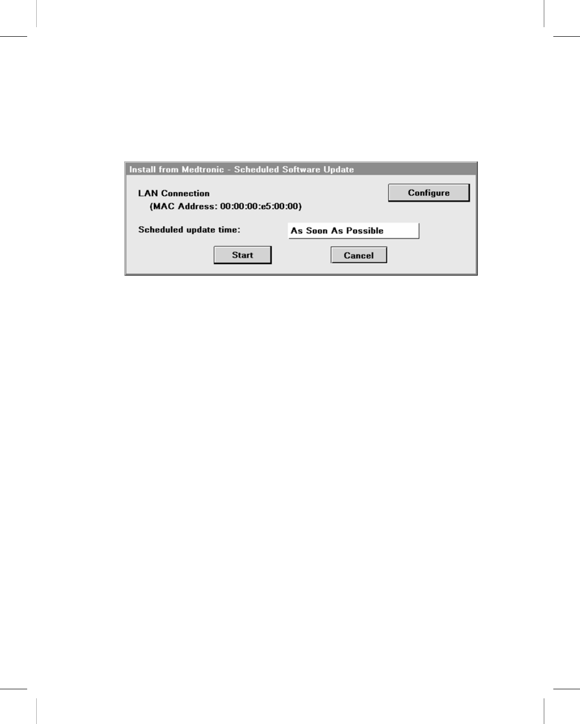
4. The programmer displays the Scheduled Software Update screen.
Choose to either start the download at a particular time by selecting a time from the
Scheduled Update Time pull-down menu, or begin the download as soon as possible
by pressing [Start].
Printing instructions: doc#163256; refer to 'Reference manuals' row in the applicable table. 501346-089
Medtronic CARELINK ENCORE™ 29901
Reference Manual 57
M945141A001B Medtronic Confidential Composed: 2012-04-26 10:35:22
XSL-Stylesheet H - Reference manual 12-MAY-2011
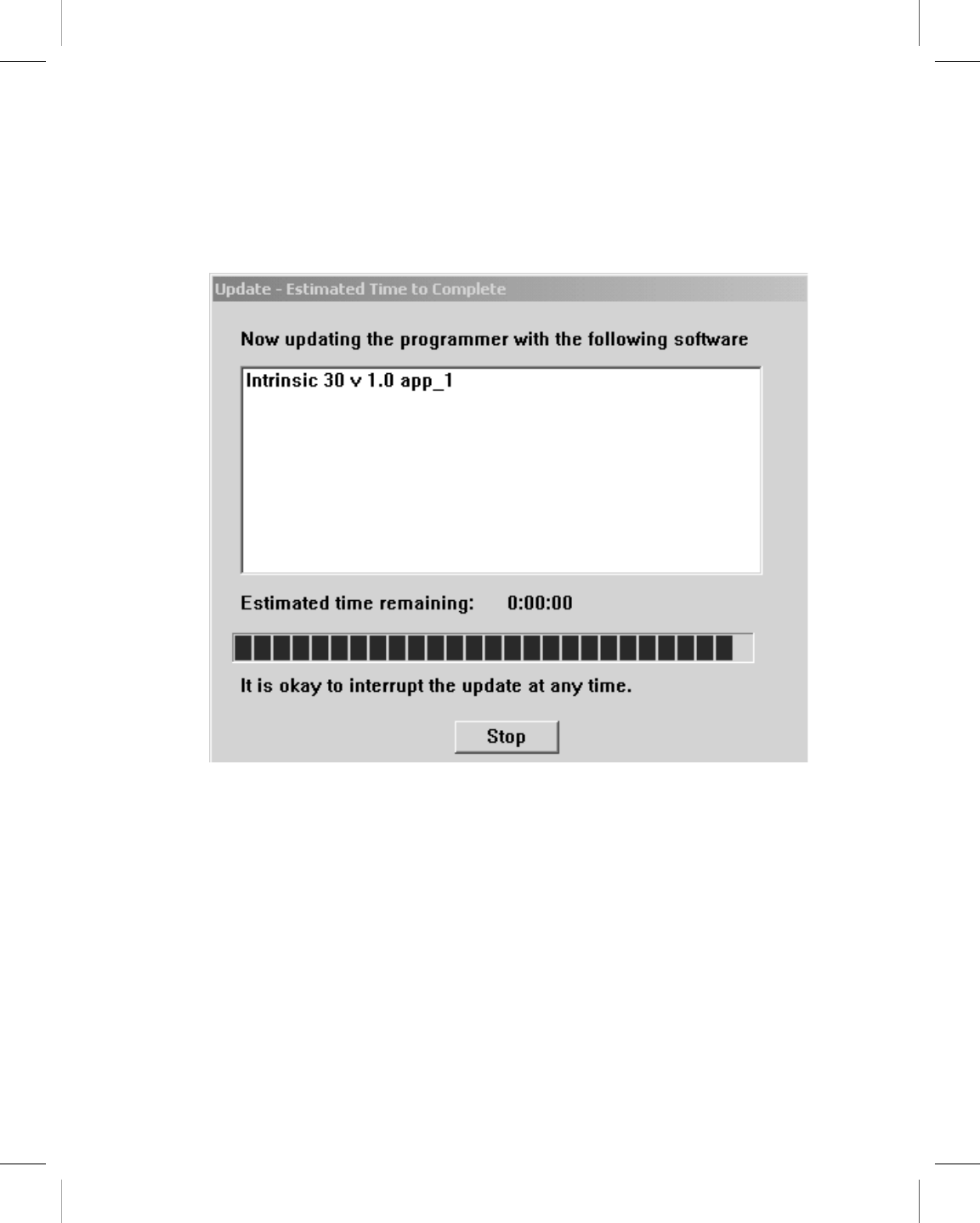
5. The Scheduled Software Update window displays a countdown window showing how
much time remains until the countdown begins. Press [Start Now] to override the
countdown or press [Cancel] to interrupt the countdown and the download request and
return to the Software on This Programmer screen.
6. The programmer displays a list of software that will download and install.
Note: Individual software cannot be selected or rejected.
You may press [Stop] at anytime and resume the download at a future time.
7. When the download is complete, the programmer disconnects from the SDN,
automatically reboots, and displays a screen listing the software that was downloaded.
8. To obtain technical manuals for the new software, see Section 1.13.
9. Press the Select Model icon. The programmer is then available for patient use.
Note: The first time the newly downloaded software is accessed, some additional
installation steps may be completed but these steps are automatic and no user intervention
is required
Printing instructions: doc#163256; refer to 'Reference manuals' row in the applicable table. 501346-089
Medtronic CARELINK ENCORE™ 29901
58 Reference Manual
M945141A001B Medtronic Confidential Composed: 2012-04-26 10:35:22
XSL-Stylesheet H - Reference manual 12-MAY-2011
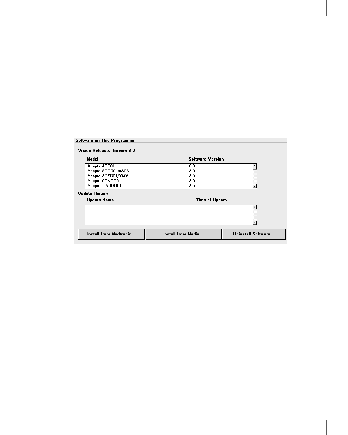
4.3 Connect to the SDN using a wireless network
connection
Note: Before you begin, make sure that the wireless connection is correctly configured. For
more information, see Section 3.13.
4.3.1 How to connect to the SDN using a wireless network connection
1. Press the Programmer icon, and then select Software.
The programmer displays the Software on This Programmer screen and lists the
software already installed on the programmer. For each model, the screen displays
the software version.
Note: The SDN cannot be accessed from Vitatron screens. Change to the Medtronic
Select Model screen.
2. Press [Install from Medtronic…].
3. Follow the prompts that are displayed to start the download.
or
Press [Cancel] if you do not agree to the terms. The download process is canceled
and the programmer redisplays the Software on This Programmer screen.
Printing instructions: doc#163256; refer to 'Reference manuals' row in the applicable table. 501346-089
Medtronic CARELINK ENCORE™ 29901
Reference Manual 59
M945141A001B Medtronic Confidential Composed: 2012-04-26 10:35:22
XSL-Stylesheet H - Reference manual 12-MAY-2011
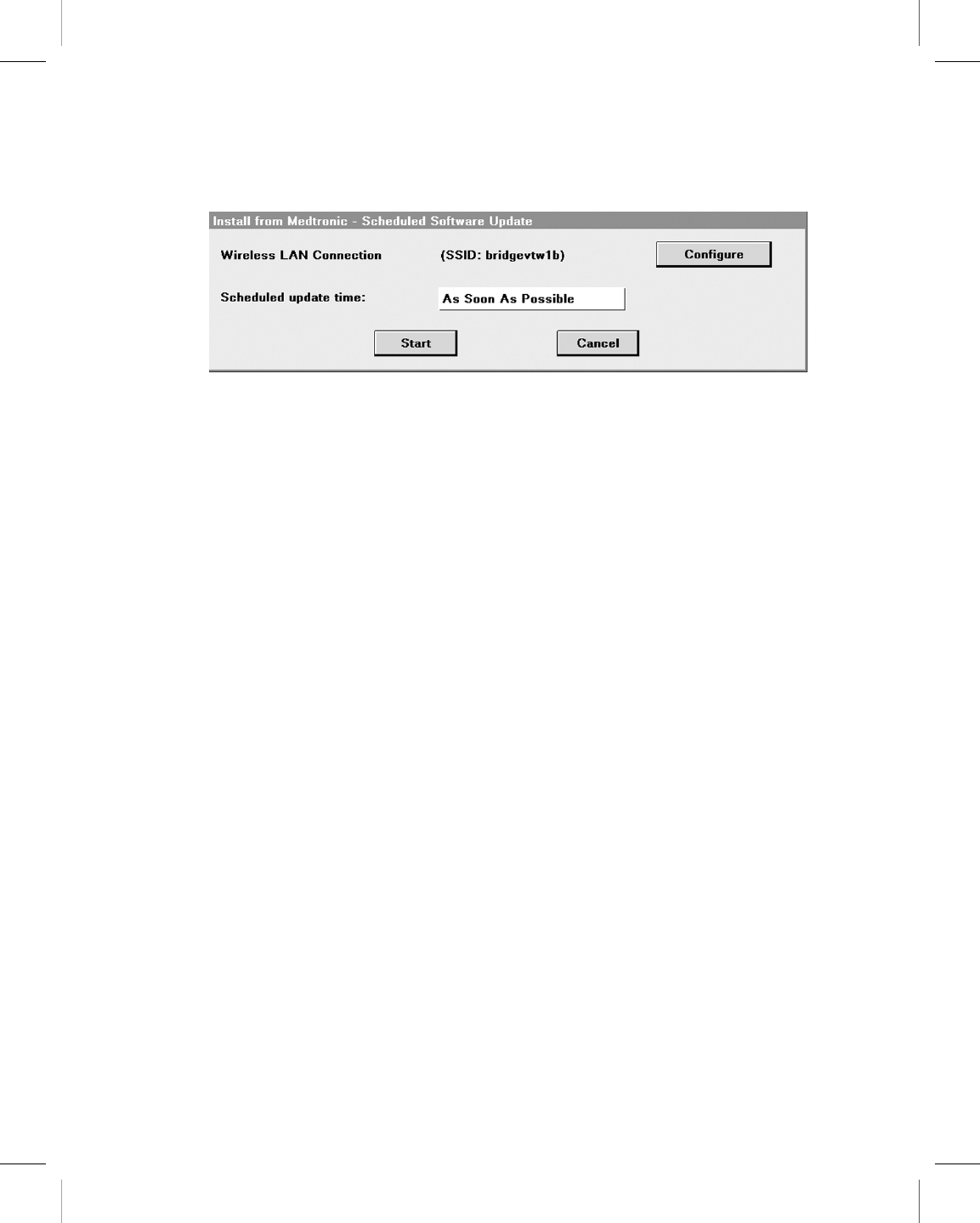
4. The programmer displays the Scheduled Software Update screen. Press [Configure].
5. On the Scheduled Software Update screen, either choose to start the download at a
particular time by selecting a time from the pull-down menu, or begin the download as
soon as possible by pressing [Start]. The programmer shuts down and displays a
window telling you to please wait.
Printing instructions: doc#163256; refer to 'Reference manuals' row in the applicable table. 501346-089
Medtronic CARELINK ENCORE™ 29901
60 Reference Manual
M945141A001B Medtronic Confidential Composed: 2012-04-26 10:35:22
XSL-Stylesheet H - Reference manual 12-MAY-2011

6. The Scheduled Software Update window displays a countdown window showing how
much time remains until the countdown begins. Press [Start Now] to override the
countdown or press [Cancel] to interrupt the countdown and the download request and
return to the Software on This Programmer screen.
7. The programmer displays a list of software that will download and install.
Note: Individual software cannot be selected or rejected.
You may press [Stop] at anytime and resume the download at a future time.
8. When the download is complete, the programmer disconnects from the SDN,
automatically reboots, and displays a screen listing the software that was downloaded.
9. To obtain technical manuals for the new software, see Section 1.13.
10. Press the Select Model icon. The programmer is then available for patient use.
Note: The first time the newly downloaded software is accessed, some additional
installation steps may be completed but these steps are automatic and no user intervention
is required.
Printing instructions: doc#163256; refer to 'Reference manuals' row in the applicable table. 501346-089
Medtronic CARELINK ENCORE™ 29901
Reference Manual 61
M945141A001B Medtronic Confidential Composed: 2012-04-26 10:35:22
XSL-Stylesheet H - Reference manual 12-MAY-2011
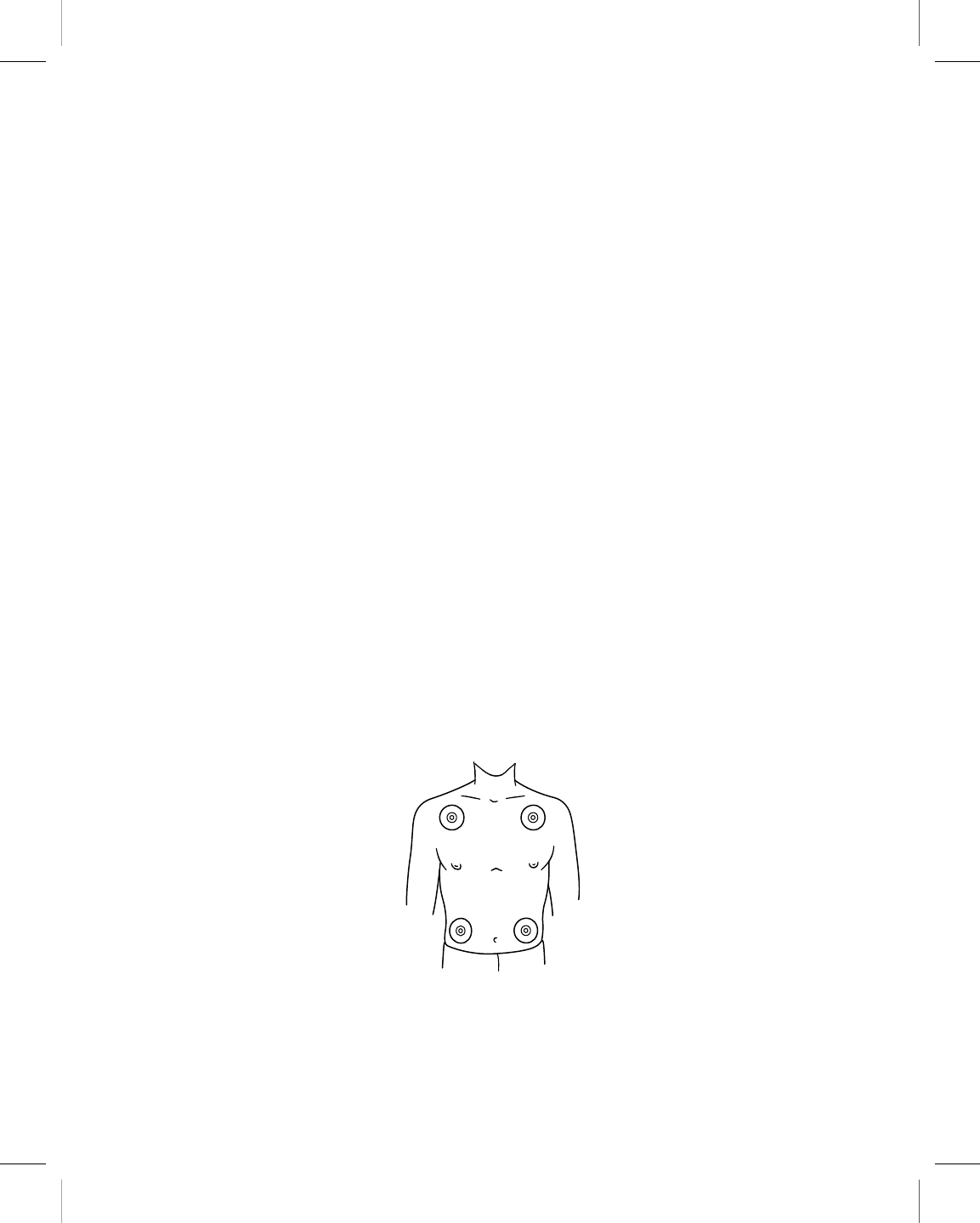
5 Conduct a patient session
5.1 Prepare for a patient session
Familiarize yourself with the information in this section before beginning a patient session.
5.1.1 Connect the programmer to skin electrodes
At the start of each patient session, ECG cable leads must be connected to the patient to
detect cardiac and pulse artifact signals.
Note: The quality of disposable skin electrodes used with the programmer is important to
the performance of the programmer signal sensing functions. Chemical reactions occur at
the electrode/paste interface and produce small DC voltages that can block the ECG signal.
Using high quality silver/silver chloride (Ag/AgCl) electrodes can minimize this problem.
Electrodes should be fresh and from the same box. The patient’s skin should be prepared
according to the directions provided with the electrodes.
Protocols covering attachment of leads to disposable skin electrodes may vary. Leads may
be attached to the electrodes either before or after the electrodes are applied to the patient.
The order of the following procedure is arbitrary.
Warning: Do not connect the programmer to wires or electrodes internal to the body. The
programmer is designed to be medically safe only when attached to surface electrodes.
5.1.2 Attach electrodes
Attach four standard, disposable electrodes to the patient in the positions shown.
Note: Electrodes are intended for one-time use and should not be reused.
Printing instructions: doc#163256; refer to 'Reference manuals' row in the applicable table. 501346-089
Medtronic CARELINK ENCORE™ 29901
62 Reference Manual
M945141A001B Medtronic Confidential Composed: 2012-04-26 10:35:22
XSL-Stylesheet H - Reference manual 12-MAY-2011
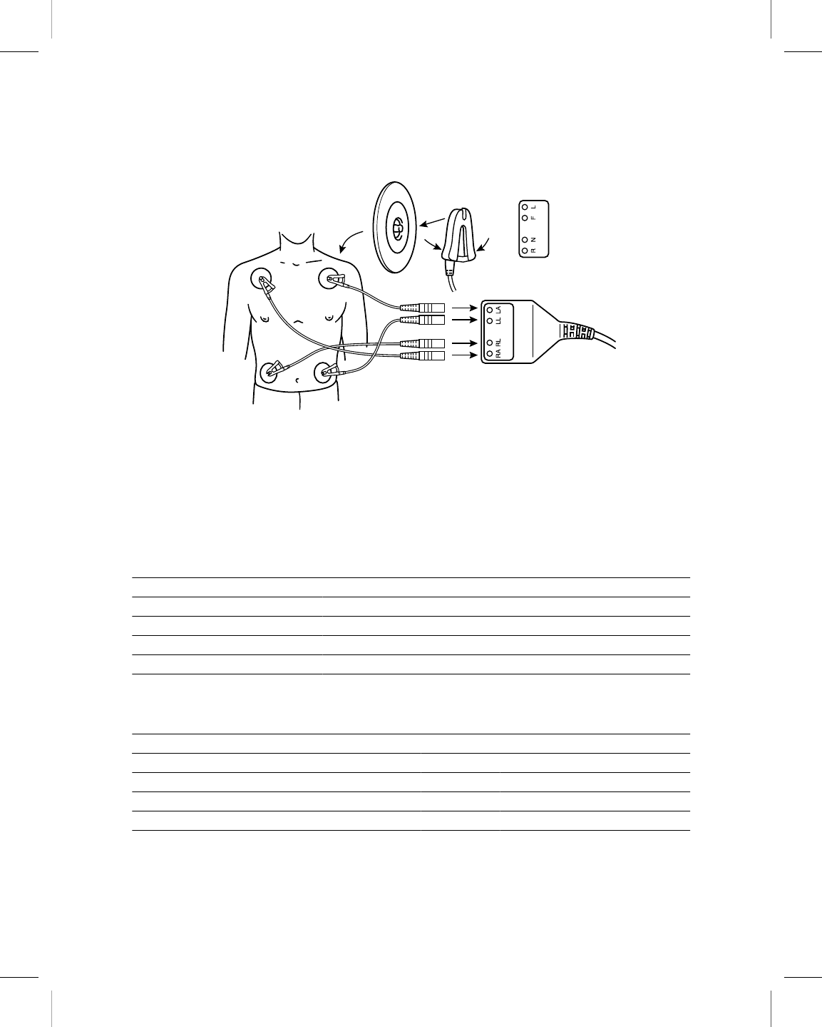
5.1.3 Connect the ECG cable
1. As shown, attach a color-coded lead wire to each of the four electrodes. Match a color
to each electrode as in Table 5.
Note: The chest lead is not used. The middle cable port of the ECG cable is sealed off
with the chest ECG plug.
2. Connect each lead wire to the ECG cable as in Table 6. Match each lead connector to
the proper cable port.
Table 5. Electrode lead wire color coding
AHA CodingaIEC CodingbBody Area
Black Yellow to left arm
Red Green to left leg
Green Black to right leg
White Red to right arm
aAmerican Hospital Association
bInternational Electrotechnical Commission
Table 6. ECG cable color coding
AHA Coding IEC Coding
Black to LA Yellow to L
Red to LL Green to F
Green to RL Black to N
White to RA Red to R
Printing instructions: doc#163256; refer to 'Reference manuals' row in the applicable table. 501346-089
Medtronic CARELINK ENCORE™ 29901
Reference Manual 63
M945141A001B Medtronic Confidential Composed: 2012-04-26 10:35:22
XSL-Stylesheet H - Reference manual 12-MAY-2011
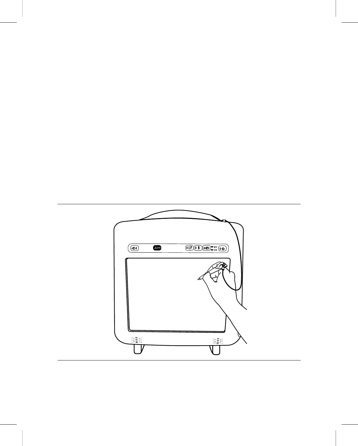
Note: Occasionally, mutual interference occurs between the programmer skin electrode
signals and signals from an external ECG recorder or monitor attached directly to the patient.
This interference may cause erratic operation of the programmer functions that depend on
surface signal detection. If interference occurs, temporarily disconnect the leads from the
attached ECG recorder or monitor. This interference does not affect the programming
functions of the programmer.
5.1.4 Use the stylus
The stylus is used to select programming functions provided by the software. Proper use of
the stylus is described in Figure 16 and in Section 5.1.5.
You can also use your finger to make selections on the screen. However, for accuracy a
stylus is recommended. Because the screen is responsive to touch, avoid resting your hand
on the screen or touching multiple screen locations while using the programmer. Avoid
pointing and touching the screen while others are using the programmer. You should also
avoid touching the screen with sharp objects.
Figure 16. Hold the stylus
Printing instructions: doc#163256; refer to 'Reference manuals' row in the applicable table. 501346-089
Medtronic CARELINK ENCORE™ 29901
64 Reference Manual
M945141A001B Medtronic Confidential Composed: 2012-04-26 10:35:22
XSL-Stylesheet H - Reference manual 12-MAY-2011

5.1.5 Select an option on the screen
Figure 17. Position the stylus
1. Move the tip of the stylus to a position directly over the desired option. If the desired
option is a displayed key or button, position the stylus tip within the rectangular outline.
If the desired option is a name or number, such as a parameter or parameter value,
position the stylus directly over the letters or numbers forming the option.
2. Touch the stylus to the screen to select an option.
Printing instructions: doc#163256; refer to 'Reference manuals' row in the applicable table. 501346-089
Medtronic CARELINK ENCORE™ 29901
Reference Manual 65
M945141A001B Medtronic Confidential Composed: 2012-04-26 10:35:22
XSL-Stylesheet H - Reference manual 12-MAY-2011
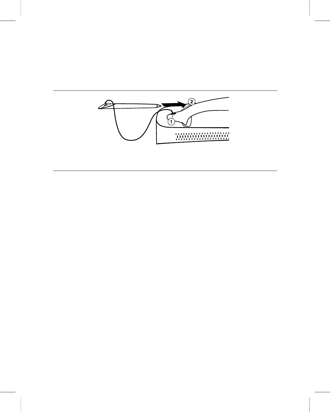
5.1.6 Attach and store the stylus
Figure 18 shows how to attach and store the stylus
Figure 18. Attach and store the stylus
1 Attach one end of the tether to the stylus and the other end to the programmer.
2 Store the stylus in the handle of the programmer by inserting it into the hollow end of the handle,
tip first.
5.1.7 Position the programming head
At some point during most applications of the programmer, the programming head must be
positioned over the implantable device. Positioning the programming head is required for
any interaction between the programmer and the implantable device.
5.1.8 When to position the programming head
Caution: Do not position the programming head over an implanted device during
electrocautery or external defibrillation procedures.
During a patient session, properly position the programming head over the implanted device
before any of the following actions:
●Selection of any command that initiates a programming transmission. The programming
head must be held in position until completion of the transmission, which usually is
indicated by a confirmation message.
●Selection of any command that initiates data transmission from the implantable device.
The programming head should be held steady until data reception is complete, which
usually is indicated by a confirmation message.
●Selection of a measurement function that requires the implantable device to be
operating asynchronously as a result of the programming head magnet.
Printing instructions: doc#163256; refer to 'Reference manuals' row in the applicable table. 501346-089
Medtronic CARELINK ENCORE™ 29901
66 Reference Manual
M945141A001B Medtronic Confidential Composed: 2012-04-26 10:35:22
XSL-Stylesheet H - Reference manual 12-MAY-2011
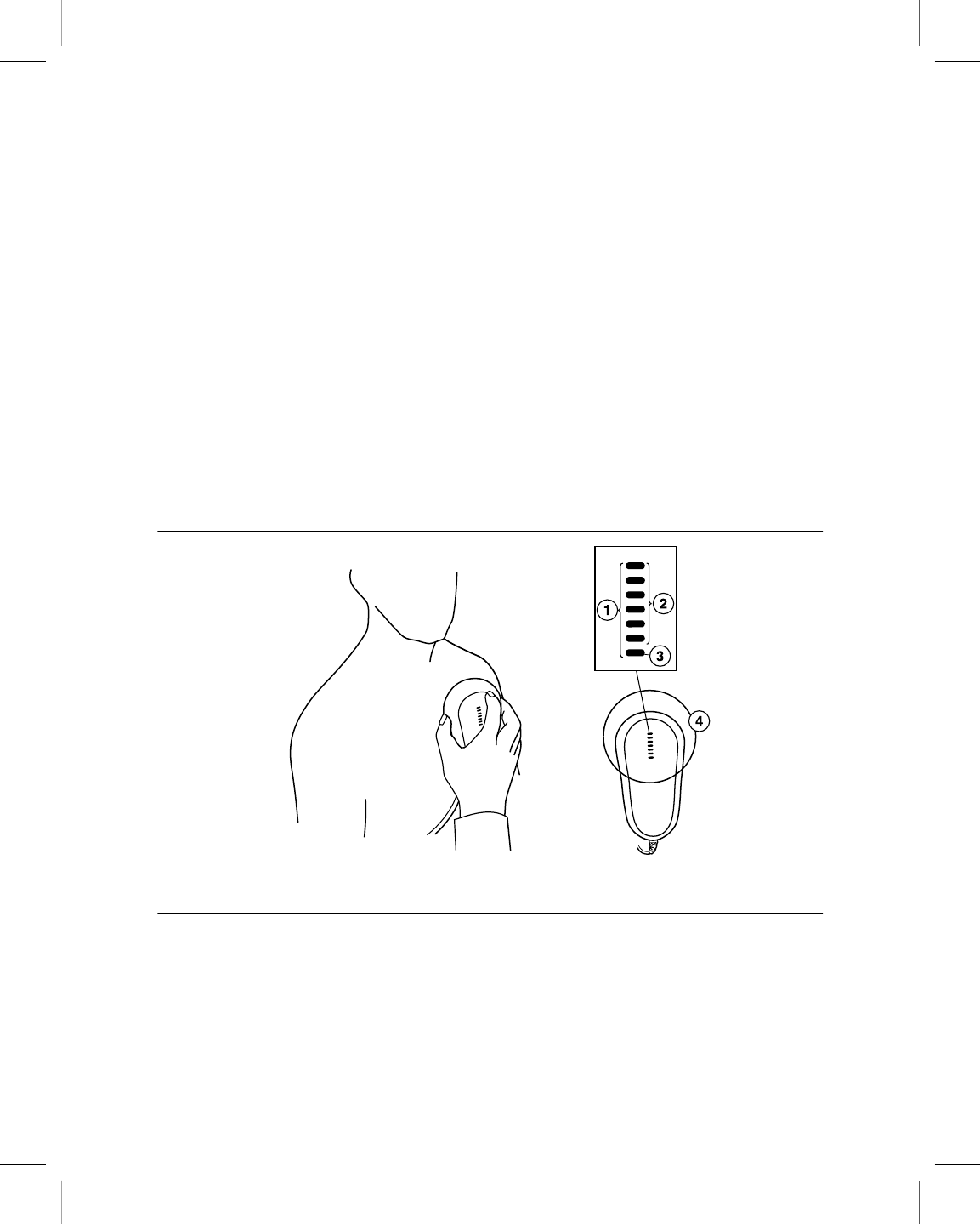
For any temporarily programmed state or function or for reception of continuous data such
as Marker Channel telemetry or EGM waveforms, the programming head must be held in
place over the implantable device for the duration of the function or until termination is
desired. Lifting the programming head cancels a temporary program and terminates
continuous telemetry. The implantable device reverts to permanently programmed values.
5.1.9 Determine the correct position
For an implantable device, the programming head should be held directly against the
patient’s skin. The face of the programming head must be parallel to and typically within
5 cm of the implantable device. Optimum position of the programming head may not be
directly centered over the implantable device. The distal end of the programming head
should be placed over the device with the device under the antenna. For best telemetry
performance, do not use the programming head close to the programmer or other sources
of electrical noise.
Figure 19. Position the programming head
1 Light array
2 Green
3 Amber/green
4 Antenna
Correct placement of the programming head is indicated in two places: the position head
array in the top left corner of the screen and the array of seven lights on the programming
head (see Figure 19).
Programming and Interrogation are not recommended when fewer than three green lights
are lit.
Printing instructions: doc#163256; refer to 'Reference manuals' row in the applicable table. 501346-089
Medtronic CARELINK ENCORE™ 29901
Reference Manual 67
M945141A001B Medtronic Confidential Composed: 2012-04-26 10:35:22
XSL-Stylesheet H - Reference manual 12-MAY-2011

Note: The number of lights used on the light array may vary for some devices. For more
information, see the Carelink Encore Programmer Software Application Supplement.
5.1.10 Program and interrogate the implanted device
1. Select the appropriate software parameters according to the reference guide for the
implanted device.
2. Position the programming head near the implanted device.
Programming and Interrogation can begin when the LED lights on the position head array
indicate satisfactory positioning and telemetry strength.
Notes:
●The programming head array shows the signal strength of the communication link.
Medtronic recommends moving the programming head to maximize the number of
green lights. All lights may not illuminate for all models. For more information, see the
reference guide for the implanted device.
●Misalignment of the programming head could result in failure of a programming
transmission and/or failure to receive data from the implantable device. Medtronic
recommends that you interrogate the device after programming to confirm that any
setting changes were successful.
5.1.11 The programming head magnet
The programming head contains a strong magnet. For more information about the effects
of a magnet, see the reference guide for the implanted device.
The programming head may attract metal instruments or may be attracted to metal surfaces.
The magnet is susceptible to partial demagnetization when it is subjected to opposing
magnetic fields, such as those present when forcing the programming head against another
magnet. The programming head should be stored as shown in Figure 22 when not in use.
Caution: Keep the programming head away from any device or material that will be
damaged by the magnetic field, including magnetic media, watches, and other electronic
devices.
Printing instructions: doc#163256; refer to 'Reference manuals' row in the applicable table. 501346-089
Medtronic CARELINK ENCORE™ 29901
68 Reference Manual
M945141A001B Medtronic Confidential Composed: 2012-04-26 10:35:22
XSL-Stylesheet H - Reference manual 12-MAY-2011

5.2 Initiate a patient session
A patient session involves the application of the various programmer functions to such
procedures as programming implantable device parameters, analyzing or assessing
implantable device operation, troubleshooting, and routine follow-up. The instructions for
using each programmer function are covered in the reference guide for the implanted
device.
Note: Before proceeding, ensure that all preparations covered in Section 2.3 and
Section 5.1 have been completed.
5.2.1 Programmer checklist
1. Is the programmer set up according to the procedures in Section 2.3?
2. Are the ECG cable, stylus, and programming head connected to the programmer?
3. Is the battery installed and charged?
4. If you are charging the battery or are using AC power instead of the battery, does the
power supply cord connect the programmer to a hospital-grade outlet?
5. Has the appropriate software been installed? Refer to Section 3.8 for a description of
how to verify the software version.
6. Are the programmer ECG cable leads connected to electrodes on the patient as
described in Section 5.1.1?
Specific information related to each implantable device model or family of models is included
in the reference guide for the device.
Before beginning a patient session, see the reference guide for the implanted device.
5.2.2 Model identification
Because the programmer collects and stores data on a session-by-session basis, it is
important to start and end each session correctly.
The programmer supports both a Medtronic and Vitatron desktop. Whichever desktop is in
use when the programmer is powered down, that same desktop appears when the
programmer is powered on. To switch from the Vitatron desktop to the Medtronic desktop
and vice versa, press the Vitatron/Medtronic switch button that appears on the bottom of
the screen.
Printing instructions: doc#163256; refer to 'Reference manuals' row in the applicable table. 501346-089
Medtronic CARELINK ENCORE™ 29901
Reference Manual 69
M945141A001B Medtronic Confidential Composed: 2012-04-26 10:35:22
XSL-Stylesheet H - Reference manual 12-MAY-2011
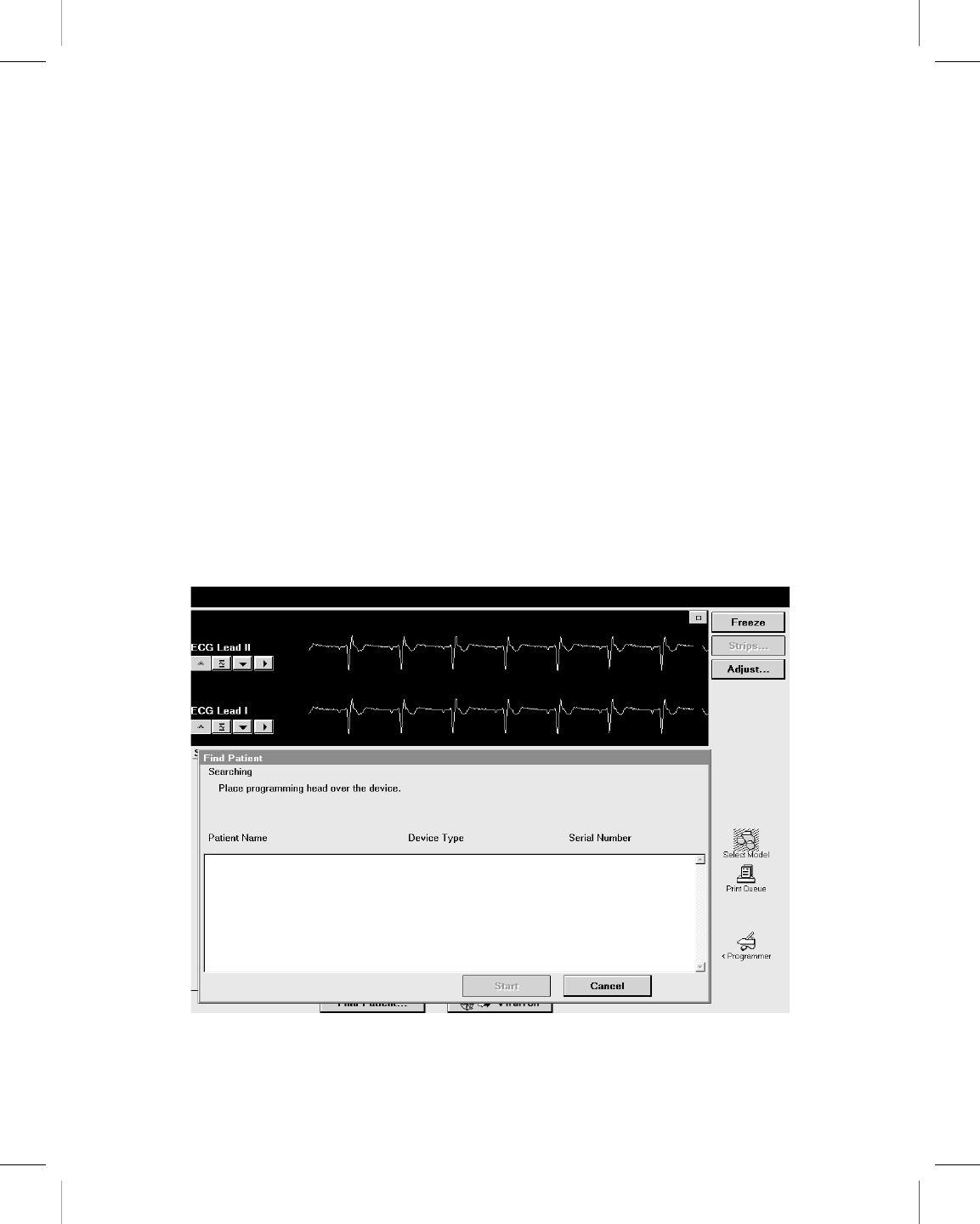
There are two ways to begin a patient session:
●Before turning on the programmer, position the programming head over the patient’s
device. When you turn on the programmer, the programmer attempts to interrogate the
device. Depending on the device, either the software application is launched
automatically or a message appears with further instructions.
●After turning on the programmer, position the programming head over the patient’s
device. During the first 5 minutes, the Medtronic desktop displays the Find Patient
screen. Afterward, it displays the Select Model screen. The Vitatron desktop displays
the Select Model screen immediately. A patient session can begin at either the Find
Patient screen or the Select Model screen. Follow the instructions on the screen that is
displayed.
5.2.2.1 Find Patient screen
When the programmer is first turned on, the Medtronic desktop displays the Find Patient
screen. If it does not detect a device within about 5 minutes, the programmer removes the
Find Patient screen to reveal the Select Model screen.
When the Find Patient screen is displayed, you may begin a patient session.
Printing instructions: doc#163256; refer to 'Reference manuals' row in the applicable table. 501346-089
Medtronic CARELINK ENCORE™ 29901
70 Reference Manual
M945141A001B Medtronic Confidential Composed: 2012-04-26 10:35:22
XSL-Stylesheet H - Reference manual 12-MAY-2011

Place the programming head over the patient’s device and hold it steady. For most devices,
the programmer identifies the device model and automatically starts up the proper software
application. If a device cannot be automatically identified, the programmer displays a
message at the top of the Find Patient screen. Perform one of the following steps, depending
on the message instructions:
●Press [Cancel] and manually select the software application from the Select Model
screen.
●Press [Cancel] and then press the Vitatron/Medtronic switch button to go to the Vitatron
desktop.
●If the message indicates that the needed software application has not been installed,
contact your Medtronic or Vitatron representative.
5.2.2.2 Select Model screen
A patient session may also begin from the Select Model screen. The Select Model screen
appears after one of the following actions:
●Shortly after the programmer has been turned on
●After you end a patient session
If the Select Model screen is not displayed, use the stylus to press the Select Model icon.
If the Select Model icon is not displayed, a patient session is in progress. You must end that
session before starting a new session.
If you are between patient sessions, you can access other screens by using the icons and
buttons described in Section 3.2.
Printing instructions: doc#163256; refer to 'Reference manuals' row in the applicable table. 501346-089
Medtronic CARELINK ENCORE™ 29901
Reference Manual 71
M945141A001B Medtronic Confidential Composed: 2012-04-26 10:35:22
XSL-Stylesheet H - Reference manual 12-MAY-2011
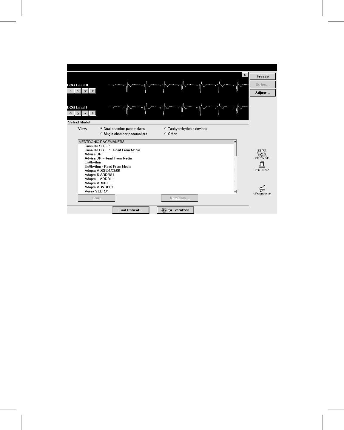
If the Select Model screen does not look like this example and you see a different button in
the command bar, press the Vitatron/Medtronic switch button to display this screen.
If the device is a Vitatron device and it is not listed on the Select Model screen, see
the Vitatron Software Programming Guide.
Position the programming head over the patient’s device and hold it steady. Press [Find
Patient] shown on the Medtronic desktop or manually select the device from the displayed
list of devices and press [Start].
When a device is manually selected from the list of devices, the programmer starts up the
application that corresponds to your selection, not the device that is under the programming
head. The Find Patient screen is displayed briefly as the programmer starts up the proper
software application. If the software application has not been installed, the programmer
displays a message indicating that the software must be installed before proceeding.
The programmer may automatically interrogate the patient’s implanted device to retrieve
most of the data that might be needed during the session. To take advantage of this
automatic interrogation, position the programming head over the implanted device and
continue to hold it in place until the interrogation is complete.
For more information about determining the model, see the reference guide for the
implanted device.
Printing instructions: doc#163256; refer to 'Reference manuals' row in the applicable table. 501346-089
Medtronic CARELINK ENCORE™ 29901
72 Reference Manual
M945141A001B Medtronic Confidential Composed: 2012-04-26 10:35:22
XSL-Stylesheet H - Reference manual 12-MAY-2011
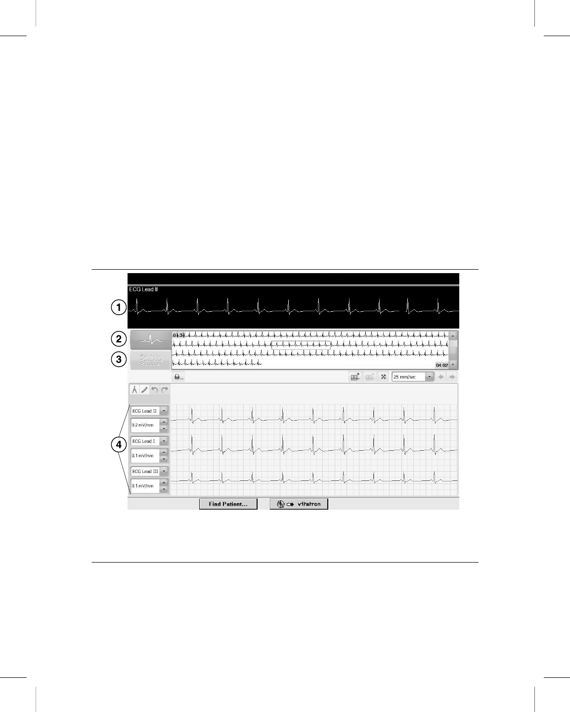
5.3 Electronic Strip Chart (eStrip) recorder
The Electronic Strip Chart (eStrip) recorder retains continuous rhythm information collected
during a session. Patient ECG and EGM are recorded without interrupting the device
application. Live rhythm is viewable in both the device application and the eStrip recorder.
The last 30 minutes of strip information is available. By highlighting areas of interest, strip
reports can be generated using the highlighted information. Highlighted strips can be viewed
using the eStrip recorder and the scale, length and other strip information can be changed.
The grid on the screen is the same size and ratio as printed strip chart paper.
5.3.1 eStrip recorder screen features
Figure 20. eStrip recorder screen
1 Real-time waveform viewer–shows real-time waveforms.
2 Holter view selector–shows overview of waveforms.
3 List view selector–shows available strips.
4 Expanded view–shows expanded view of a segment of a waveform.
Printing instructions: doc#163256; refer to 'Reference manuals' row in the applicable table. 501346-089
Medtronic CARELINK ENCORE™ 29901
Reference Manual 73
M945141A001B Medtronic Confidential Composed: 2012-04-26 10:35:22
XSL-Stylesheet H - Reference manual 12-MAY-2011
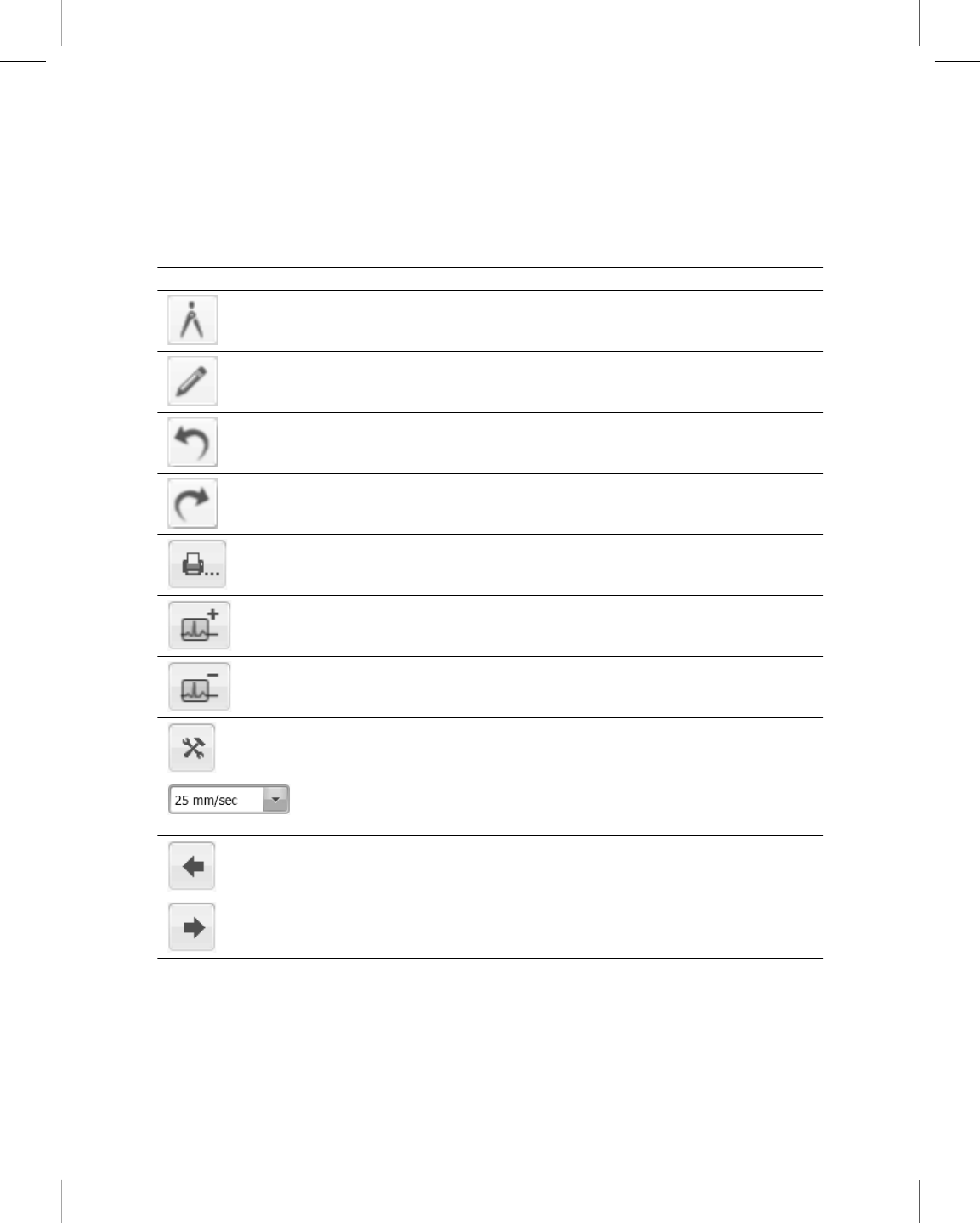
5.3.2 eStrip recorder screen icons/selectors
The eStrip recorder screen contains these icons/selectors:
Table 7. Icons/selectors on the eStrip recorder screen
Icon Name Function
Caliper Initiates interval caliper tool.
Markup tool Provides ability to draw notes on a waveform.
Undo Erase the most recent caliper or markup.
Redo Replaces the most recently erased caliper or
markup.
Print Opens the print screen.
Add highlight Add highlight to previously unhighlighted wave-
form.
Remove highlight Removes existing highlight from a waveform.
Strip preferences Opens preferences screen.
Chart speed adjust Presents chart speed choices. Selecting a new
chart speed changes data presentation in expan-
ded view based on new chart speed.
Previous highlight Navigates to previous highlight.
Next highlight Navigates to next highlight.
Printing instructions: doc#163256; refer to 'Reference manuals' row in the applicable table. 501346-089
Medtronic CARELINK ENCORE™ 29901
74 Reference Manual
M945141A001B Medtronic Confidential Composed: 2012-04-26 10:35:22
XSL-Stylesheet H - Reference manual 12-MAY-2011
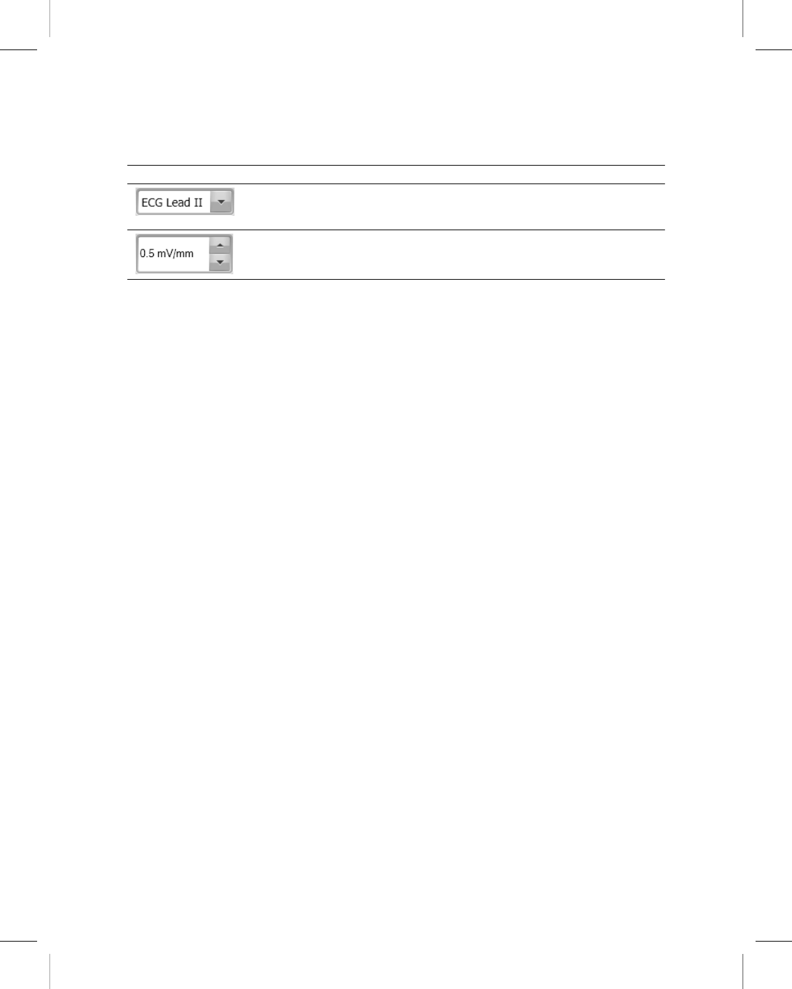
Table 7. Icons/selectors on the eStrip recorder screen (continued)
Icon Name Function
Lead/vector selector Changes the lead/vector in the expanded view.
Selecting None removes the lead/vector from the
expanded view.
Gain adjust Changes trace gain.
5.3.3 Highlight an area of interest during a session
1. Press the Electronic Strip Chart (eStrip) button on the button panel to highlight an area
of interest.
2. Open the eStrip recorder from the Task bar to view the highlight.
5.3.4 Change the length of a strip
1. Select a strip.
2. Press and hold the border of the strip.
3. Drag the border of the strip to make it longer or shorter.
5.3.5 Measure intervals using calipers
1. Select a strip.
2. Press the Caliper icon.
3. Press the arrow icon on the bottom right corner of the strip to walk the calipers.
4. To save caliper measurement to strip, press the tack icon.
5.3.6 Change the name of a strip
1. Press the List View button to display available strips.
2. Press the name of the strip in the expanded view on the bottom half of the screen.
3. Change the name of the selected strip by either typing a new name when the keyboard
displays or selecting a name from the library by clicking the down arrows next to the
name field.
4. Press [OK].
Printing instructions: doc#163256; refer to 'Reference manuals' row in the applicable table. 501346-089
Medtronic CARELINK ENCORE™ 29901
Reference Manual 75
M945141A001B Medtronic Confidential Composed: 2012-04-26 10:35:22
XSL-Stylesheet H - Reference manual 12-MAY-2011
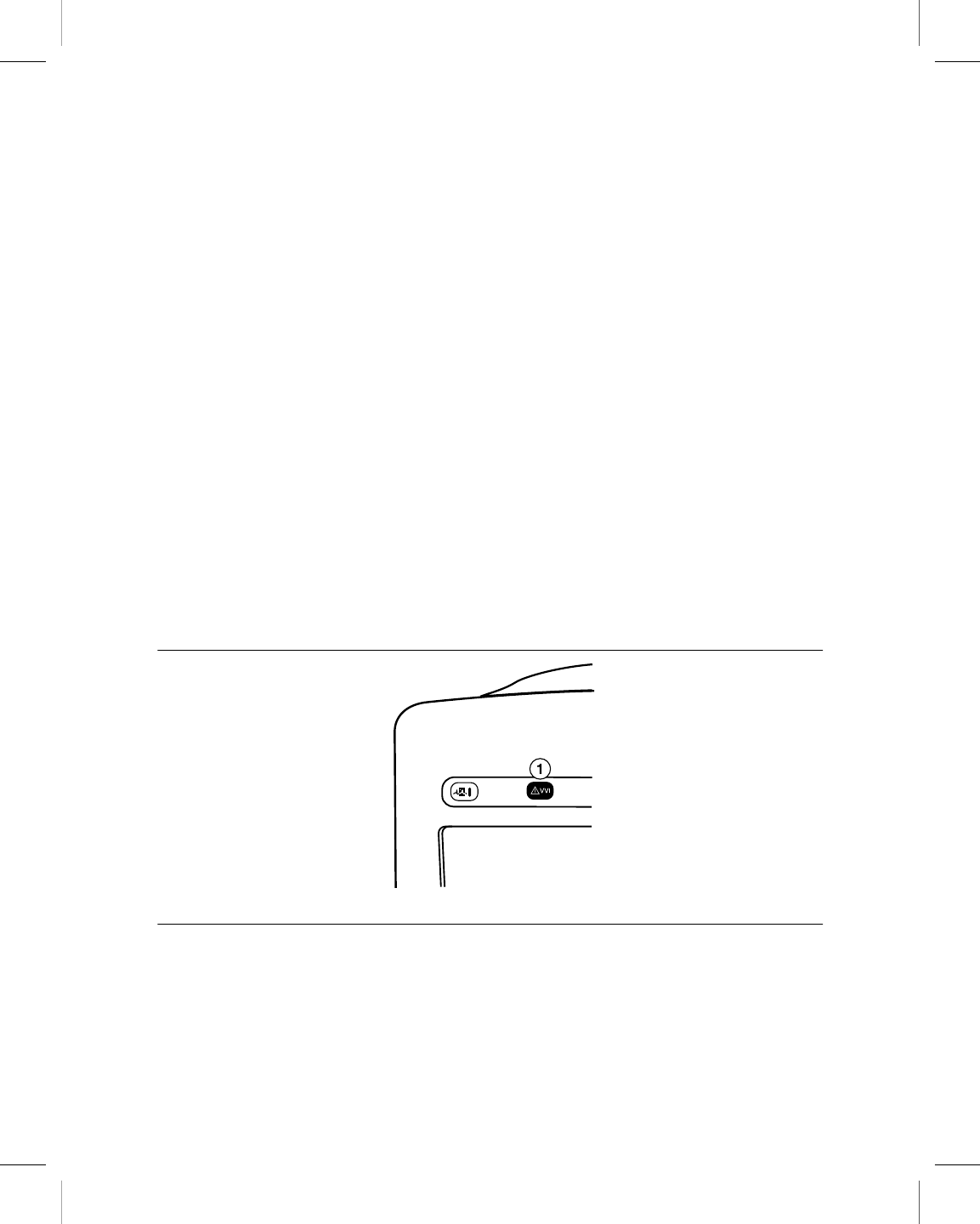
5.3.7 Create test strip report from the eStrip recorder
1. Run a test in the device application.
2. Open the eStrip recorder from the Task bar.
3. Press the List View button to display available strips.
4. Select the strip or strips you want to use to create a report.
5. Press the Print icon.
6. From the Reports – Strip Chart window, press [Print Now] to print the report or [Save
to PDF File] to save the report to PDF. You can select the number of copies to print or
press Select Strips to change which strips will be included in the report.
Note: To save a report to PDF, you must have a USB flash drive connected to the
programmer where the PDF will be saved to.
5.4 Emergency VVI button
The red emergency VVI button on the programmer button panel provides immediate access
for emergency VVI pacing during a patient session. Pressing the red emergency VVI button
displays the emergency screen options and delivers VVI pacing.
Figure 21. Programmer button panel
1 Red emergency VVI button
Specific parameter values for emergency VVI pacing are determined by each device
application. The red emergency VVI button may be available after a system error.
Printing instructions: doc#163256; refer to 'Reference manuals' row in the applicable table. 501346-089
Medtronic CARELINK ENCORE™ 29901
76 Reference Manual
M945141A001B Medtronic Confidential Composed: 2012-04-26 10:35:22
XSL-Stylesheet H - Reference manual 12-MAY-2011

Note: For all ICD applications, the [Emergency] button is also implemented in the software
and is available from the display screen. For more information on the [Emergency] button
available from the display screen, see the reference guide for the implanted device.
5.4.1 Deliver emergency bradycardia pacing
To initiate emergency pacing, correctly position the programming head over the implanted
device and press the red emergency VVI button. A message confirms programming, and
emergency VVI operation begins.
5.4.2 Deliver emergency tachyarrhythmia therapy
To deliver therapy, press the red emergency VVI button to display the emergency screen
on the programmer and press the on-screen [Deliver] button.
For complete instructions regarding the use of the [Deliver] button for specific applications,
see the appropriate device Reference Guide, System Reference Guide, or Clinician
Manual.
5.5 End a patient session
When you want to end a patient session, you may save data to a supported storage device
or end the session without saving.
Refer to the reference guide for the implanted device for specific information on saving
device data.
Printing instructions: doc#163256; refer to 'Reference manuals' row in the applicable table. 501346-089
Medtronic CARELINK ENCORE™ 29901
Reference Manual 77
M945141A001B Medtronic Confidential Composed: 2012-04-26 10:35:22
XSL-Stylesheet H - Reference manual 12-MAY-2011
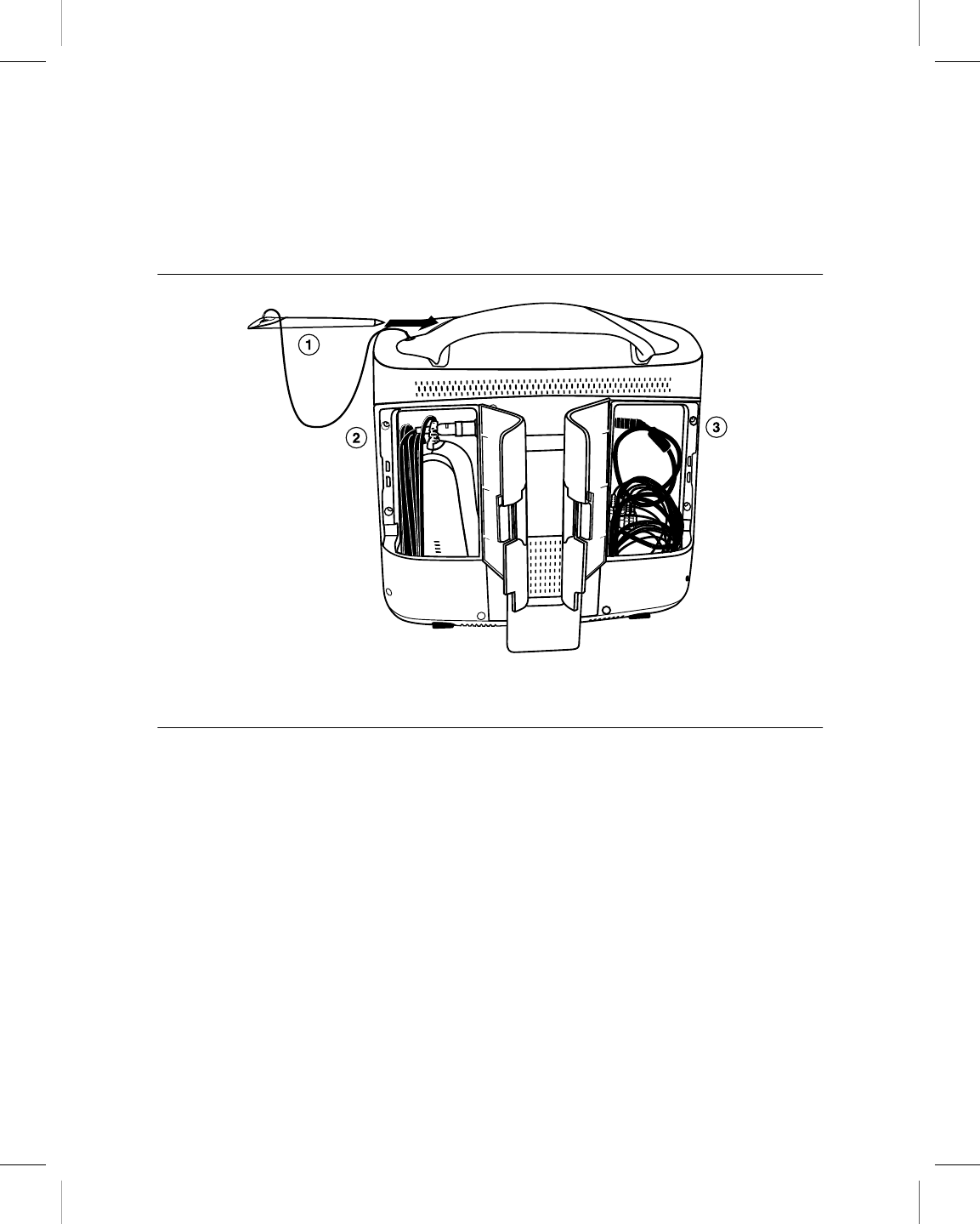
5.6 Store components
Figure 22 shows the proper way to store components.
Figure 22. Store components
1 Store the stylus in the handle of the programmer.
2 Store the programming head in the left rear door.
3 Store the ECG cable in the right rear door.
Printing instructions: doc#163256; refer to 'Reference manuals' row in the applicable table. 501346-089
Medtronic CARELINK ENCORE™ 29901
78 Reference Manual
M945141A001B Medtronic Confidential Composed: 2012-04-26 10:35:22
XSL-Stylesheet H - Reference manual 12-MAY-2011

6 Manage session data and reports
6.1 Session data
Patient session data may be saved to a USB flash drive.
6.2 Reports
Depending on the implanted device model, various types of reports can be created. Refer
to the reference guide for the implanted device for specific information on report types and
contents. During an active session, reports may be printed, or saved as PDF files on a USB
flash drive. Reports held for later printing may be printed while at the desktop or when
returning to a session. Reports might not be available for later printing from the desktop,
depending on the device application and on the current print queue deletion schedule. For
more information, see Section 6.9.
6.3 Save to a PDF file
Printable reports, frozen strips, and other data may be saved to a PDF file. A PDF file is an
electronic version of a printed document; therefore, the feature is accessible under the
printing commands.
To save to a PDF file, perform the following steps:
1. Open or create the report or file.
2. Press [Print…] or [Print Options…] to display the Print – Options dialog box.
Note: If the Print – Options dialog box does not display, open Preferences, and then
select the Printing: Pop up these options when any print button is selected check
box.
3. From the list of supported printers, select the Save to PDF File option. The report is
saved to an attached USB flash drive. For more information on saving to USB, see
Section 6.4.
Printing instructions: doc#163256; refer to 'Reference manuals' row in the applicable table. 501346-089
Medtronic CARELINK ENCORE™ 29901
Reference Manual 79
M945141A001B Medtronic Confidential Composed: 2012-04-26 10:35:22
XSL-Stylesheet H - Reference manual 12-MAY-2011
6.4 Save to USB
Many device applications support the use of USB flash drives for saving and loading session
data.
Note: Device applications and reference manuals may still use the terms “disk” or “diskette”
in the context of saving and retrieving device data. When a USB flash drive is connected to
the programmer and available for use as described below, the terms disk or diskette should
be interpreted as applying to the USB flash drive, rather than the diskette.
6.4.1 Supported USB storage devices
In order to ensure the integrity and security of patient health information, it is recommended
that you use USB flash drives that are dedicated to storing programmer data only.
6.4.2 Operation
A USB flash drive should be connected or disconnected while at the desktop or in a session.
Connect a writable USB flash drive to the programmer using any available USB port. A slight
delay may occur while the USB flash drive is authorized. The USB indicator on the task bar
turns green to indicate that the USB flash drive is available for use.
Note: The USB ports on the programmer are USB 2.0.
Figure 23. USB indicator status
1 No USB connected
2 USB connected
USB flash drives should not be connected or disconnected while the following actions are
in progress:
●Programming a device
●Performing a Save to Media
●Performing a Read from Media
●Saving a report as a PDF file
Printing instructions: doc#163256; refer to 'Reference manuals' row in the applicable table. 501346-089
Medtronic CARELINK ENCORE™ 29901
80 Reference Manual
M945141A001B Medtronic Confidential Composed: 2012-04-26 10:35:22
XSL-Stylesheet H - Reference manual 12-MAY-2011

Notes:
●While a Save to Media action is in progress, the progress indicator and the message
“Saving…” display. The progress indicator displays the completion percentage. Before
removing the USB flash drive, wait a few seconds after the progress indicator shows
100%.
●After a report is saved as a PDF file, the message “PDF report(s) saved to media” is
displayed for about 5 seconds. Wait a few seconds after the message goes away before
removing the USB flash drive.
●If an active session is ended while reports are currently printing or pending, the reports
are canceled and may not be available from the desktop print queue.
Any action to read or write data (such as Save to Media, Read from Media, save reports to
a PDF file) will use the USB flash drive after it is connected. Refer to the reference guide for
the implanted device for specific information on saving device data. For more information
on saving reports to PDF file, see Section 6.3.
Connect only one writable USB flash drive at a time. Connecting two or more USB flash
drives results in an error during data-saving operations. This condition is indicated by the
USB disabled icon.
6.5 View reports that are saved to media
Saved report PDFs may be viewed on the programmer or on a computer.
All reports from one patient’s session are contained in one PDF file. File names are
automatically assigned according to a naming convention that ensures uniqueness on the
storage media:
●Patient’s name (if previously provided in Patient Information)
●Device serial number
●“Session Report”
●Clinic visit date in MM_DD_YY format
●Version number (the first PDF saved to this storage media gets “1”)
For example: John Q Patient_aaannnnnna_Session Report_06_25_10_1.PDF
Printing instructions: doc#163256; refer to 'Reference manuals' row in the applicable table. 501346-089
Medtronic CARELINK ENCORE™ 29901
Reference Manual 81
M945141A001B Medtronic Confidential Composed: 2012-04-26 10:35:22
XSL-Stylesheet H - Reference manual 12-MAY-2011

6.6 View reports on the programmer using PDF Viewer
The PDF Viewer allows you to view and print PDF reports previously saved on a USB flash
drive.
1. Connect a USB flash drive with saved PDF reports.
2. Select the PDF Viewer in the taskbar. The list of the available PDF files on the USB
flash drive is displayed in the left panel.
3. Click the file name to open a preview of the PDF. To open the PDF, press [Open
document] or double-click the PDF file name
PDF files on the USB flash drive other than previously-saved PDF reports are also viewable
with the PDF Viewer.
●You can use the toolbar at the top of the PDF to go to a specific page, increase or
decrease the size of the document, or search within the PDF.
●To hide the list of PDFs to provide a larger viewing area for the PDF, press [Hide] in the
lower left corner of the PDF viewer. To restore the list, press [Show].
●To print a PDF, with a report open in the PDF Viewer, press the Print icon.
6.7 Viewing and printing PDF files on a computer
Insert the USB flash drive containing the reports into a computer equipped to display files
that are in PDF format.
Due to computer and software variations, some PDF files may not be displayed properly
when viewed on a computer monitor.
The use of Adobe Reader 9 or later is recommended. Adjusting the following settings may
reduce or eliminate display imperfections:
●Replace document colors with white page background and black text (in Adobe Reader
9, select: Edit > Preferences > Accessibility > Replace Document Colors > Custom
Color)
●Deselect the option to enhance thin lines (in Adobe Reader 9, select: Edit > Preferences
> Page Display)
Imperfections that may be seen on screen:
●On graphs that contain rectangles drawn with thin lines, e.g., bar graphs, the thin lines
may not be displayed at various zoom levels.
●On Pacing and Tachy Trigger Episode reports, unfilled circles may be displayed as filled
circles.
Printing instructions: doc#163256; refer to 'Reference manuals' row in the applicable table. 501346-089
Medtronic CARELINK ENCORE™ 29901
82 Reference Manual
M945141A001B Medtronic Confidential Composed: 2012-04-26 10:35:22
XSL-Stylesheet H - Reference manual 12-MAY-2011
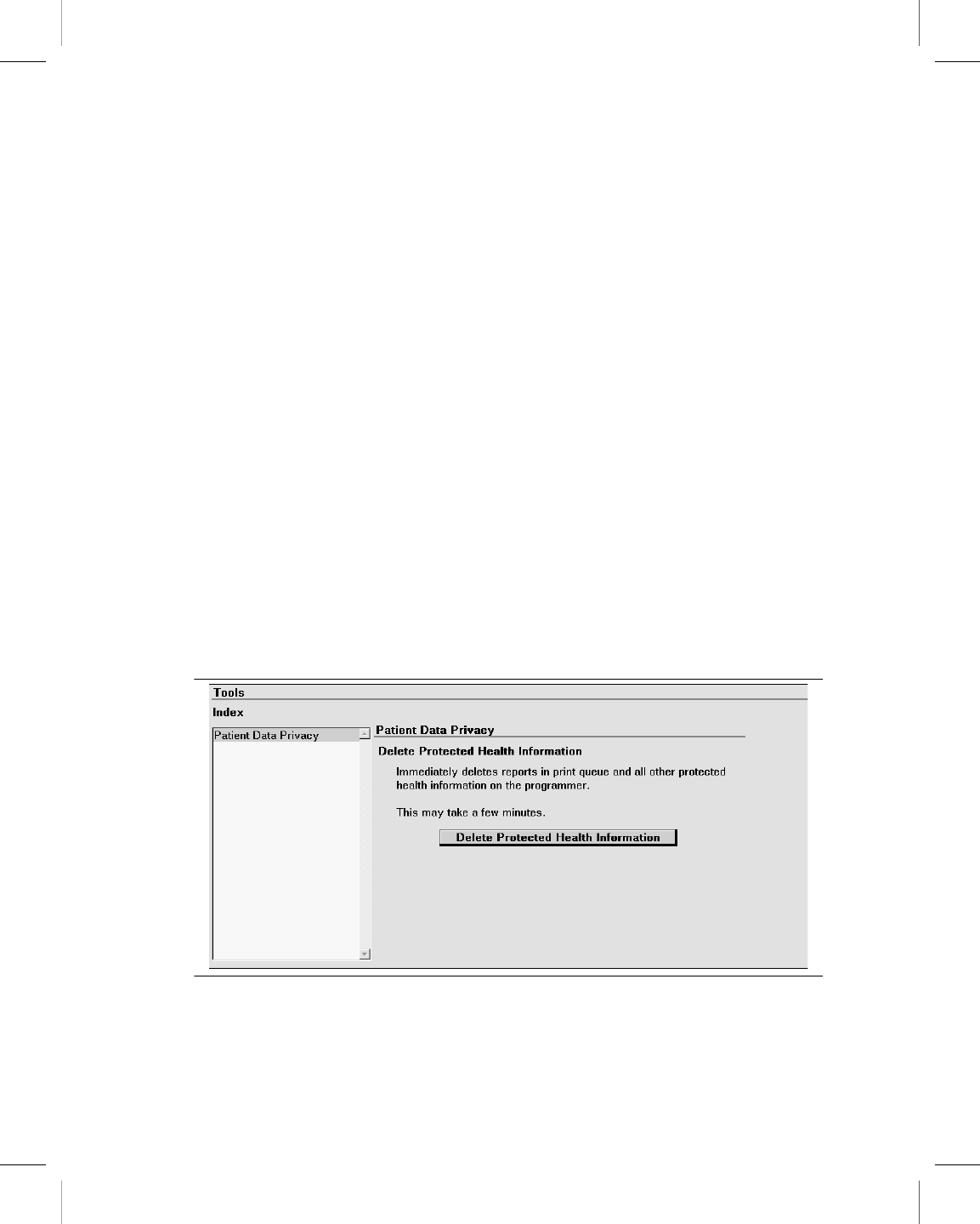
PDF reports print properly at a resolution of 300 dpi or greater.
6.8 Manage patient data privacy
You can immediately remove from the programmer all Protected Health Information (PHI).
This feature deletes all of the following files:
●Contents of the Print Queue (unless files are currently being printed or copied)
●Temporary files residing on the programmer
●Memory dumps (applies to Vitatron devices only)
You cannot delete any PHI data if a session is in progress or while files are being printed or
copied to media. If deletion is interrupted manually, some PHI remains on the programmer.
Note: The user of the programmer is responsible for the use of this feature, as well as for
management of patient data that has already been removed from the programmer (for
example on paper or a USB flash drive).
6.8.1 Delete Protected Health Information
1. Press the Programmer icon, and then select Tools. The programmer displays the
Tools screen as shown in Figure 24.
Figure 24. Tools screen with Patient Data Privacy index item selected
2. Press [Delete Protected Health Information]. The programmer displays the dialog box
as shown in Figure 25.
Printing instructions: doc#163256; refer to 'Reference manuals' row in the applicable table. 501346-089
Medtronic CARELINK ENCORE™ 29901
Reference Manual 83
M945141A001B Medtronic Confidential Composed: 2012-04-26 10:35:22
XSL-Stylesheet H - Reference manual 12-MAY-2011
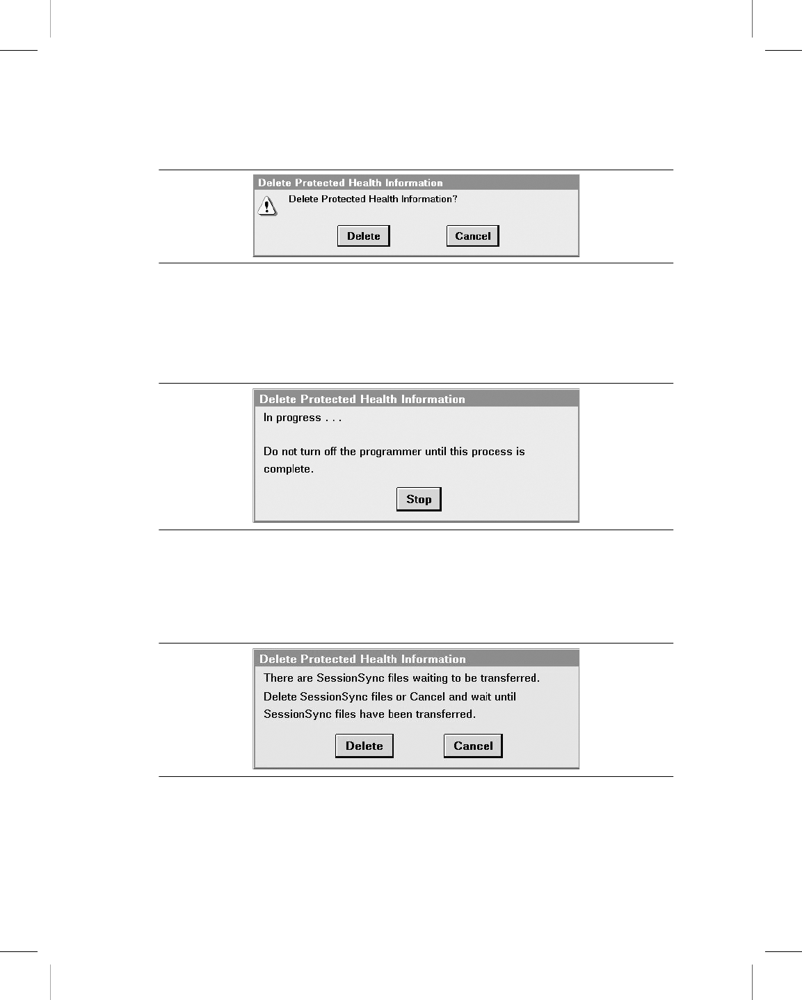
Figure 25. Delete Protected Health Information confirmation dialog box
3. Press [Delete] to continue.
One of the following events may occur:
The programmer displays an “In progress…” dialog box as shown in Figure 26. Deletion
may last several minutes, depending on the amount of data to delete.
Figure 26. In progress dialog box
If there are SessionSync files on the programmer that have not been transferred yet,
the programmer displays a message indicating that there are SessionSync files waiting
to be transferred, as shown in Figure 27. Press [Delete] to delete the SessionSync files
or [Cancel] to wait until the SessionSync files have transferred.
Figure 27. SessionSync files waiting dialog box
If there are reports currently printing, the programmer displays a message directing
you to wait until printing is complete, as shown in Figure 28. Press [Close].
Printing instructions: doc#163256; refer to 'Reference manuals' row in the applicable table. 501346-089
Medtronic CARELINK ENCORE™ 29901
84 Reference Manual
M945141A001B Medtronic Confidential Composed: 2012-04-26 10:35:22
XSL-Stylesheet H - Reference manual 12-MAY-2011
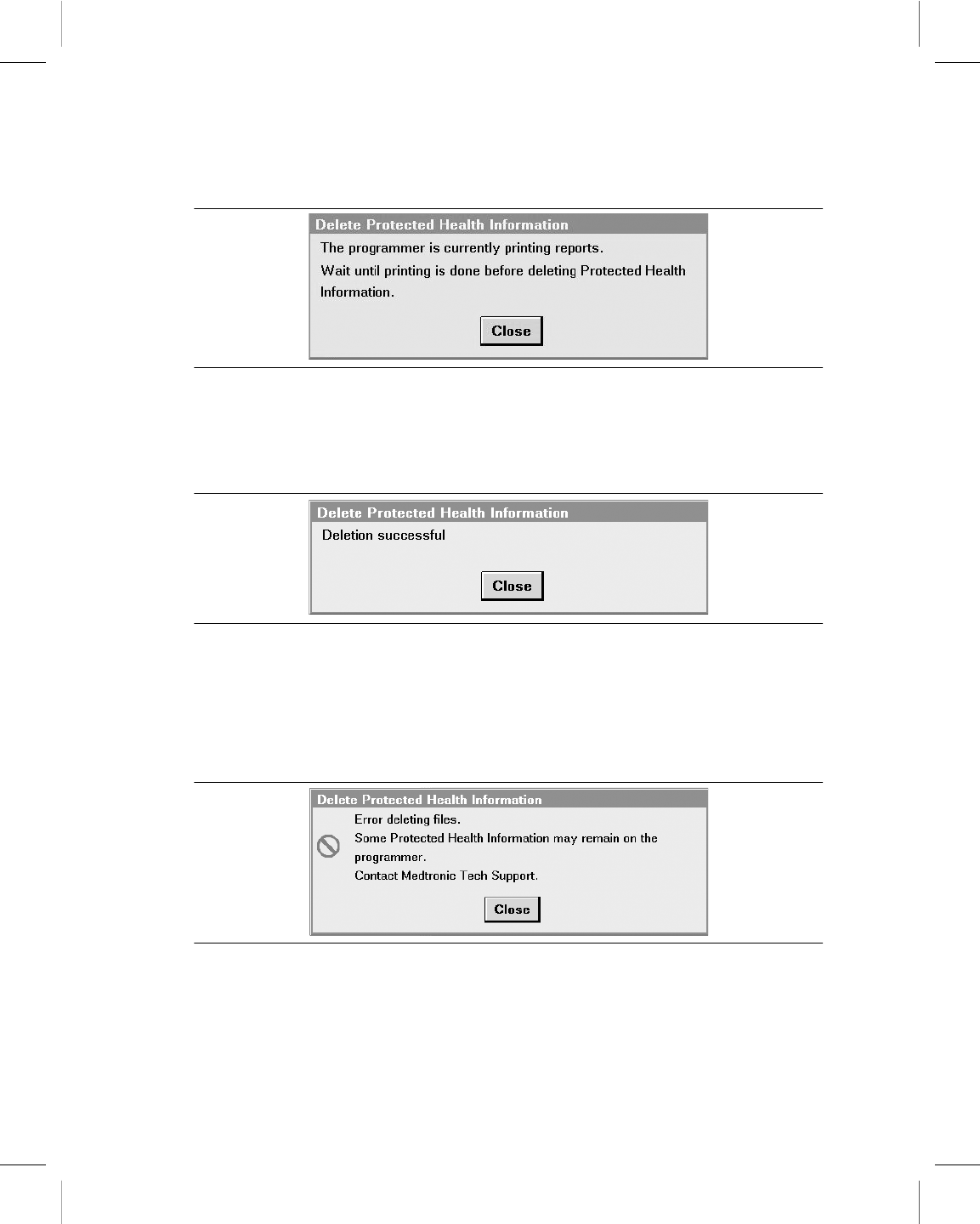
Figure 28. Printing in progress dialog box
4. If pressing [Delete] in Step 3 resulted in protected health information deletion, the
programmer displays a message stating that deletion was successful, as shown in
Figure 29. Press [Close].
Figure 29. Deletion successful dialog box
Or,
If the programmer is unable to complete deletion of files, it displays a message stating
that there was an error and that some data may remain on the programmer, as shown
in Figure 30. Press [Close]. Contact Medtronic Technical Support if the message
recurs.
Figure 30. Error deleting files dialog box
Printing instructions: doc#163256; refer to 'Reference manuals' row in the applicable table. 501346-089
Medtronic CARELINK ENCORE™ 29901
Reference Manual 85
M945141A001B Medtronic Confidential Composed: 2012-04-26 10:35:22
XSL-Stylesheet H - Reference manual 12-MAY-2011
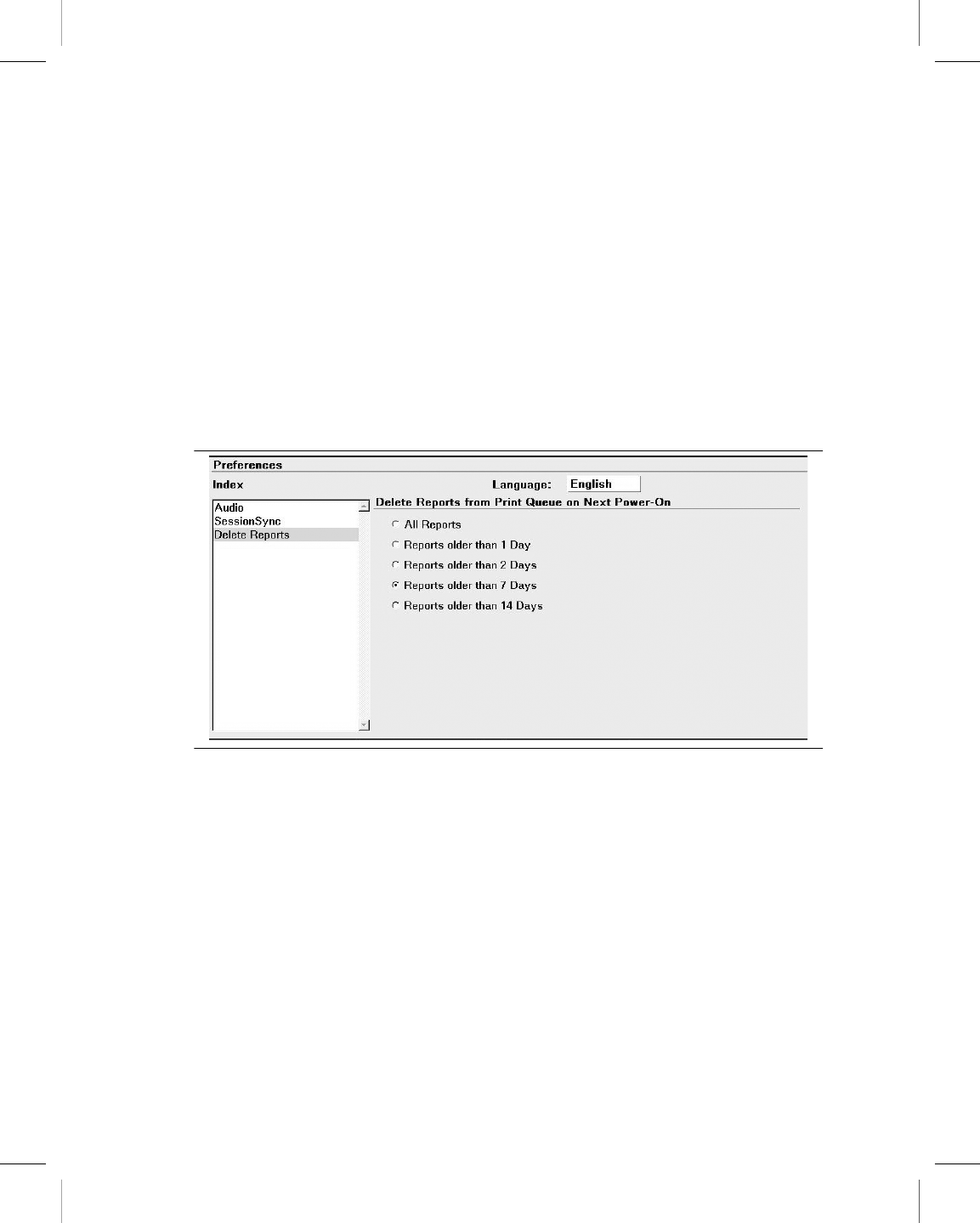
6.9 Set the interval for report deletion
For patient data security, the programmer permanently deletes reports automatically from
the Medtronic desktop print queue at the time when the programmer is powered up. You
can control how long reports are retained in the print queue before automatic deletion.
6.9.1 Select a report deletion interval
1. Press the Programmer icon, and then select Preferences.
2. From the Preferences screen, select Delete Reports. The programmer displays the
Delete Reports screen as shown in Figure 31.
Figure 31. Delete Reports screen
3. Select a radio button to specify which reports the programmer deletes:
●All Reports
●Reports older than 1 Day
●Reports older than 2 Days
●Reports older than 7 Days (Default)
●Reports older than 14 Days
The age of a report is determined by the date and time it was created. When the programmer
is powered on, reports that meet the deletion criteria are permanently deleted.
Printing instructions: doc#163256; refer to 'Reference manuals' row in the applicable table. 501346-089
Medtronic CARELINK ENCORE™ 29901
86 Reference Manual
M945141A001B Medtronic Confidential Composed: 2012-04-26 10:35:22
XSL-Stylesheet H - Reference manual 12-MAY-2011

6.9.2 Delete a report immediately
To delete a report immediately, directly access it from the print queue and press [Delete].
Printing instructions: doc#163256; refer to 'Reference manuals' row in the applicable table. 501346-089
Medtronic CARELINK ENCORE™ 29901
Reference Manual 87
M945141A001B Medtronic Confidential Composed: 2012-04-26 10:35:22
XSL-Stylesheet H - Reference manual 12-MAY-2011
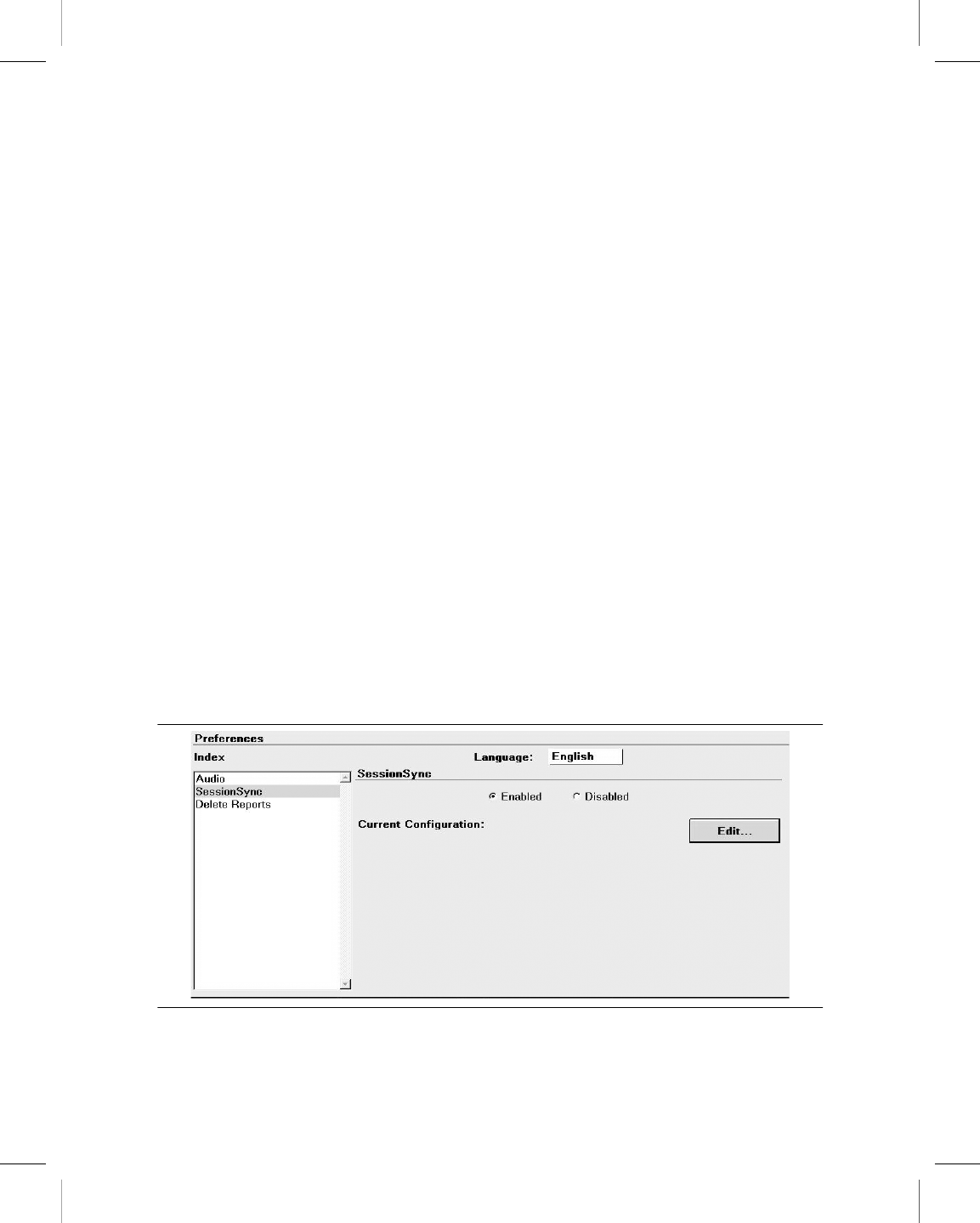
7 SessionSync (Optional)
7.1 About SessionSync
SessionSync is an optionally installed feature that provides network connectivity between
the programmer and the Medtronic Paceart data management system. Using your clinic’s
network, the programmer can send downloaded device data through SessionSync to the
data management system.
The SessionSync status icon and the SessionSync status screen provide information on
the connection status of the programmer to the data management system.
You must configure the programmer network settings to allow for this data transfer.
7.2 Enable and disable SessionSync
1. Select Programmer > Preferences.
2. Select SessionSync from the Index menu.
3. Select [Enabled] to enable SessionSync or Select [Disabled] to disable SessionSync.
Note: The SessionSync icon in the task bar will be grayed out when the feature is disabled.
SessionSync functions are not available within a patient session unless you have enabled
this feature prior to starting a patient session.
Figure 32. Preferences screen with Session Sync selected
Printing instructions: doc#163256; refer to 'Reference manuals' row in the applicable table. 501346-089
Medtronic CARELINK ENCORE™ 29901
88 Reference Manual
M945141A001B Medtronic Confidential Composed: 2012-04-26 10:35:22
XSL-Stylesheet H - Reference manual 12-MAY-2011
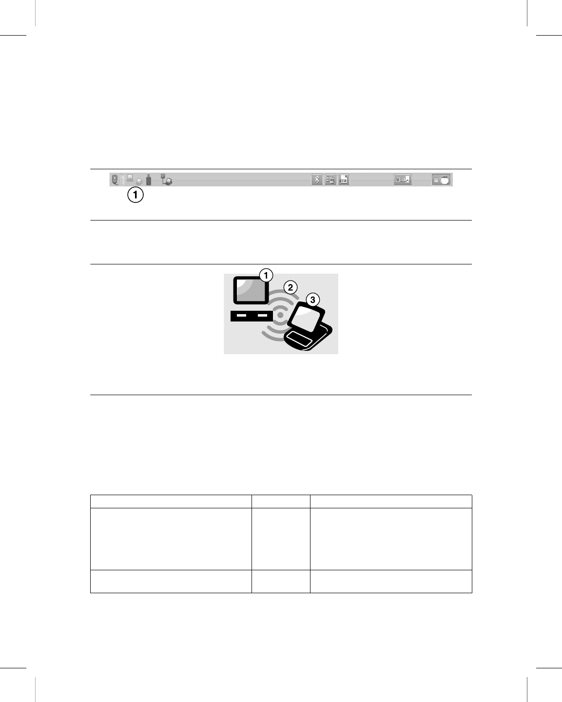
7.3 SessionSync Status icon
The SessionSync status icon provides information on the network connection between the
programmer and the data management system.
Figure 33. The task bar with the SessionSync Status icon
1 The SessionSync Status icon
If SessionSync is not installed on the programmer, the icon is not visible in the task bar.
Figure 34. Parts of the SessionSync Status icon
1 The data management system status
2 The connection status between the programmer and the data management system
3 The programmer status
The sections of the SessionSync Status icon change colors to indicate data ready for
transfer, a valid connection between the programmer and the data management system,
and successful data transfer to the data management system.
Note: When the whole icon is grayed out, SessionSync has been disabled under the
programmer preferences.
Table 8. SessionSync Status icon states
Part of SessionSync Status Icon Color What the color indicates
Programmer Gray No session data files are in the Transfer
Queue.
Note: The transfer queue is the list of
session data files that have been saved
to the programmer hard disk but are wait-
ing for transfer.
Blue Session data files exist in the Transfer
Queue
Printing instructions: doc#163256; refer to 'Reference manuals' row in the applicable table. 501346-089
Medtronic CARELINK ENCORE™ 29901
Reference Manual 89
M945141A001B Medtronic Confidential Composed: 2012-04-26 10:35:22
XSL-Stylesheet H - Reference manual 12-MAY-2011

Table 8. SessionSync Status icon states (continued)
Part of SessionSync Status Icon Color What the color indicates
Connection Not visible No valid connection exists between the
programmer and the data management
system
Green Valid connection exists between the pro-
grammer and the data management sys-
tem
Red circle
with a line
through it
Device application in use does not sup-
port SessionSync
Data Management System Gray No session data has been transferred to
the data management system
Blue All session data has been successfully
transferred to the data management sys-
tem
7.4 Use Automatic SessionSync
Automatic SessionSync allows you to perform a SessionSync automatically at the end of a
patient session. This feature is available for all SessionSync enabled devices.
7.4.1 Save the patient session with Manual SessionSync
1. Press the Session icon.
2. Select SessionSync….
3. The SessionSync - Saving Session Data On Programmer window is opened and for
some devices an interrogation is automatically started. The SessionSync - Saving
Session Data On Programmer window shows the progress of the save. The
Programmer side of the SessionSync Status icon turns blue after the data has been
saved on the Programmer hard disk. If the subsequent transfer is successful, the data
management system side of the SessionSync Status icon turns blue.
7.4.2 End a patient session with Automatic SessionSync enabled
1. Press [End Session…]. If an interrogation is required before the SessionSync data
transfer, the Interrogation Required window is displayed.
2. Verify that the Automatic SessionSync box is checked, and then press [End Now].
Printing instructions: doc#163256; refer to 'Reference manuals' row in the applicable table. 501346-089
Medtronic CARELINK ENCORE™ 29901
90 Reference Manual
M945141A001B Medtronic Confidential Composed: 2012-04-26 10:35:22
XSL-Stylesheet H - Reference manual 12-MAY-2011

3. The SessionSync - Saving Session Data On Programmer window is opened. For some
devices, an interrogation is automatically started. The SessionSync - Saving Session
Data On Programmer window shows the progress of the save. The programmer side
of the SessionSync Status icon turns blue after the data has been saved on the
programmer hard disk. If the subsequent transfer is successful, the data management
system side of the SessionSync Status icon turns blue.
7.5 Use Manual SessionSync for supported devices
Manual SessionSync allows you to send interrogated data to the Paceart data management
system without ending the patient session on the Programmer.
Manual SessionSync is not available for all SessionSync supported devices. If manual
SessionSync is available for a device, the SessionSync… option appears in the
Session menu.
7.6 SessionSync error message descriptions
You may receive error or information messages at different times in the SessionSync
process. For a list of error messages, see Table 9. If you have any issues with the
programmer contact Medtronic Technical Support at the telephone number on the back
cover of this manual.
Table 9. SessionSync error messages
Error Message What it means
Data Transfer Failed A device communication error has occurred during the interrog-
ation and you have cancelled out of the interrogation window. The
session data has not been saved on the programmer hard disk.
Do one of the following:
Press [Retry] to retry the operation.
Press [Cancel] to close the window.
Ending a Session without Auto-
matic SessionSync
You have cleared the Automatic SessionSync check box on the
End Session window before pressing the [End Now] button.
Interrogation Required You must conduct an interrogation before starting a SessionSync
data transfer for this device.
Press [OK] to close the window.
Printing instructions: doc#163256; refer to 'Reference manuals' row in the applicable table. 501346-089
Medtronic CARELINK ENCORE™ 29901
Reference Manual 91
M945141A001B Medtronic Confidential Composed: 2012-04-26 10:35:22
XSL-Stylesheet H - Reference manual 12-MAY-2011
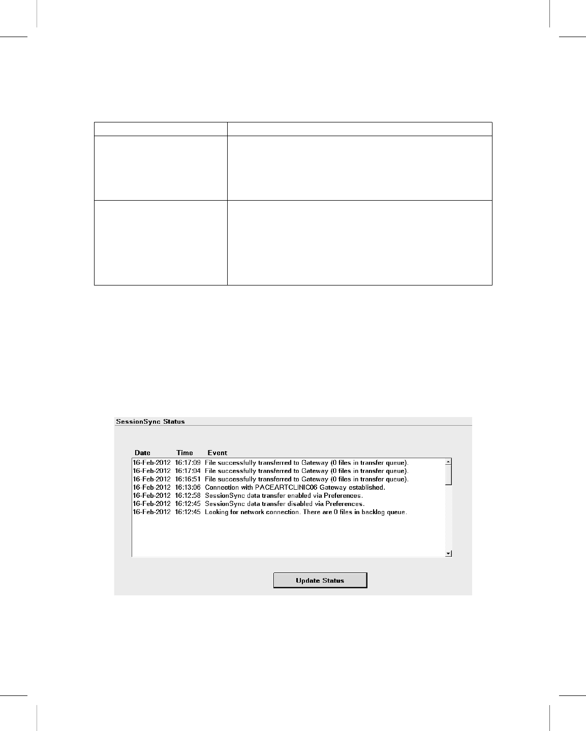
Table 9. SessionSync error messages (continued)
Error Message What it means
Interrogate - Unsuccessful The programmer cannot interrogate the device. You must repo-
sition the programming head.
Do one of the following:
Press [Retry] or [Continue] after repositioning the programming
head.
Press [Cancel] to close the window.
Unable to Save Session Data The session data cannot be saved on the programmer hard disk.
Do one of the following:
Press [Save to Disk] or [Save Session] to save the session data
on a floppy disk.
Press [End Now] to end the session without saving the device
data.
Press [Cancel] to close the window without saving the device
data.
7.7 View SessionSync Status screen
The SessionSync Status screen displays information on the data files being transferred to
the data management system using SessionSync. Each message includes the date, time,
and event information for the associated SessionSync event.
7.8 Update SessionSync status
Printing instructions: doc#163256; refer to 'Reference manuals' row in the applicable table. 501346-089
Medtronic CARELINK ENCORE™ 29901
92 Reference Manual
M945141A001B Medtronic Confidential Composed: 2012-04-26 10:35:22
XSL-Stylesheet H - Reference manual 12-MAY-2011

1. Press the Programmer icon, and then select SessionSync Status.
2. Press [Update Status].
Note: SessionSync status does not dynamically update when the window is open. To
update, press [Update Status].
Printing instructions: doc#163256; refer to 'Reference manuals' row in the applicable table. 501346-089
Medtronic CARELINK ENCORE™ 29901
Reference Manual 93
M945141A001B Medtronic Confidential Composed: 2012-04-26 10:35:22
XSL-Stylesheet H - Reference manual 12-MAY-2011

8 Service the programmer
8.1 Clean the system components
The exterior surfaces of the programmer and its accessories may be cleaned with a sponge
or soft cloth moistened with water, mild detergent, hydrogen peroxide, or alcohol.
Thoroughly clean the surfaces of the programmer wires; the bottom surface of the
programming head; and the wire connecting the programming head to the programmer.
Caution: Take care to prevent liquid from entering the programmer and programming head.
Do not immerse the programmer or any accessories in any liquid or clean them with aromatic
or chlorinated hydrocarbons.
The lead wires may be cleaned by wiping each lead wire with a sponge or soft cloth
moistened with the cleaning material, then wiped with a sponge or soft cloth moistened with
clean water, and then wiped dry.
The exterior surfaces of the lead wires can be cleaned up to 15 times with each of the
following materials without functional degradation:
●Green soap, green soap tincture, or alcohol-free hand soap
●2% gluteraldehyde solution (such as Cidex)
●Sodium hypochlorite (bleach solution 10% in water)
8.2 Sterilize the programming head, ECG cable, and
lead wires
Except for the programming head or ECG cable and lead wires, the programmer and its
accessories cannot be sterilized.
Caution: Do not autoclave the programming head or ECG cable and lead wires.
Visually inspect the cable and connections of the programming head after sterilizing. Do
not use the programming head if it appears damaged. Damage includes, but is not limited
to, deterioration of the cable insulation (brittleness, cracking, thinning, or bare spots). Do
not use the programming head if the conductive wires are exposed.
Printing instructions: doc#163256; refer to 'Reference manuals' row in the applicable table. 501346-089
Medtronic CARELINK ENCORE™ 29901
94 Reference Manual
M945141A001B Medtronic Confidential Composed: 2012-04-26 10:35:22
XSL-Stylesheet H - Reference manual 12-MAY-2011

8.2.1 Ethylene oxide
Note: The programming head or ECG cable and lead wires must be completely dry before
being ethylene-oxide sterilized.
1. Wrap the programming head or ECG cable and lead wires in packaging permeable to
ethylene oxide.
2. Medtronic recommends normal gas concentration of 725 mg/L ethylene oxide followed
by a minimum of 12 hours of aeration. The worst case cycle will consist of no more
than 3 hours exposure to EO.
3. Do not exceed 55 °C, 50% RH.
4. Do not resterilize the programming head more than 20 EO cycles. Do not resterilize
the ECG cable and lead wires more than 10 EO cycles.
Biological indicators should be used to ensure that proper sterilization standards have been
met. A previously validated sterilization cycle should be used.
Due to the variability in sterilization systems, precise sterilization instructions cannot be
provided. Contact the manufacturer of your sterilization system for more information
regarding procedures.
8.2.2 Gas plasma (programming head only STERRAD 100S gas plasma
system)
1. Place the programming head in packing material appropriate for gas plasma
sterilization.
2. Sterilize by procedures validated for effectiveness using suitable biological controls.
a. Do not exceed 55 °C.
b. Do not use an H2O2 concentration below 1 mg/L (nominal 1.8 mg/L).
c. Do not expose the programming head to a sterilizer cycle longer than 72 min
(nominal 55 min).
d. Do not resterilize the programming head more than 20 cycles.
Printing instructions: doc#163256; refer to 'Reference manuals' row in the applicable table. 501346-089
Medtronic CARELINK ENCORE™ 29901
Reference Manual 95
M945141A001B Medtronic Confidential Composed: 2012-04-26 10:35:22
XSL-Stylesheet H - Reference manual 12-MAY-2011
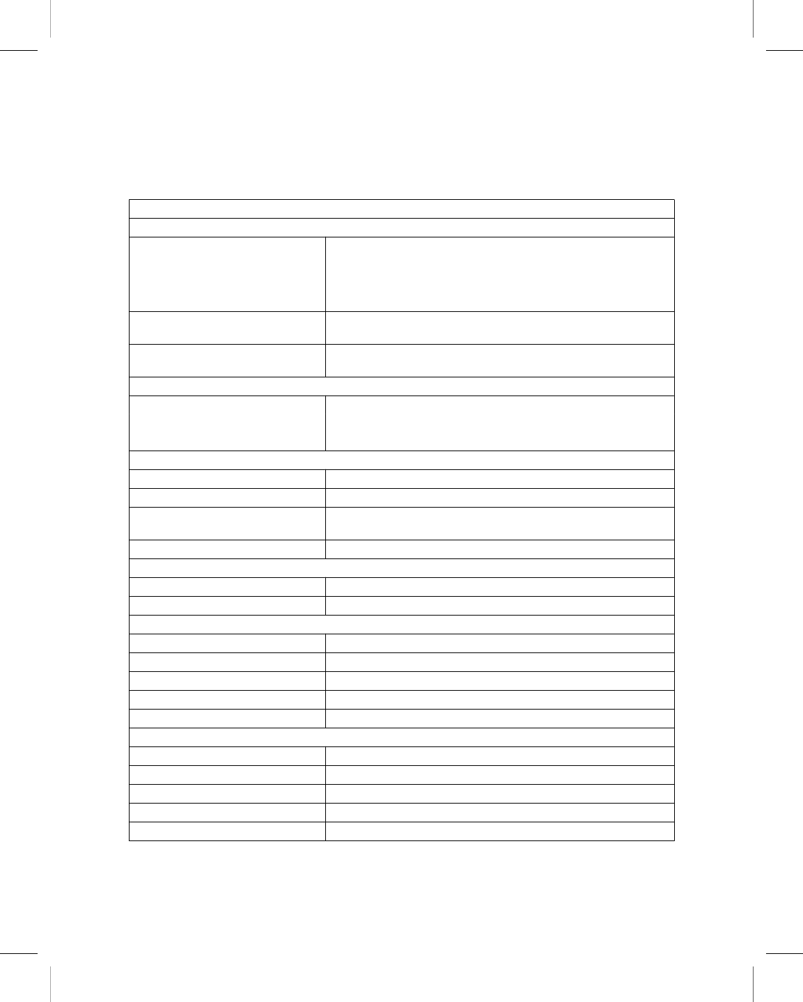
8.3 Programmer specifications
Table 10. Programmer specifications
Standards (The programmer complies with the following:)
Radio frequency wireless specifications and applicable standards
EMC EN / IEC 60601-1-2
EN 301 489
EN 302 195
EN 55022 Class B/CISPR 22
EN 55024 Class B/CISPR 24
Radio FCC CFR 47 P.15
RSS-210
Patient safety UL/CUL 60601-1, Class I, Type BF ordinary EN 60601-1, Class
I, Type BF, continuous operation
AC power requirement
Voltage 100 to 125 VAC nominal or 200 to 240 VAC nominal
Frequency 50/60 Hz nominal
Power 100 W
Battery
Type Li-ion, rechargeable
Capacity 3900 mAh
Charge duration Standby: 15 days
Operating: 2 hours (typical)
Voltage 11.1 V
Power cord
AC/DC adapter in 100-240 VAC 1.5 A @ 50/60 Hz
AC/DC adapter out 19 VDC 5.3 A
Electrical safety requirements per IEC 60601-1:1988, Clause 19
Enclosure leakage current ≤ 0.1 mA
Earth leakage current ≤ 0.5 mA
Patient leakage current A.C. ≤ 0.1 mA
Patient auxiliary current D.C. ≤ 0.01 mA
Patient auxiliary current A.C. ≤ 0.1 mA
Electrical safety requirements per IEC 60601-1:2005, Clause 8.7
Touch leakage current ≤0.1 mA
Earth leakage current ≤0.1 mA
Patient leakage current A.C. ≤0.1 mA
Patient auxiliary current D.C. ≤ 0.01 mA
Patient auxiliary current A.C. ≤0.1 mA
Printing instructions: doc#163256; refer to 'Reference manuals' row in the applicable table. 501346-089
Medtronic CARELINK ENCORE™ 29901
96 Reference Manual
M945141A001B Medtronic Confidential Composed: 2012-04-26 10:35:22
XSL-Stylesheet H - Reference manual 12-MAY-2011
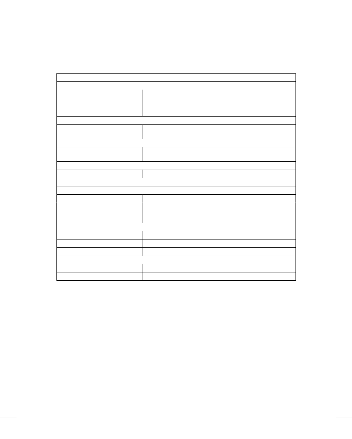
Table 10. Programmer specifications (continued)
Standards (The programmer complies with the following:)
Physical dimension and weight
Height
Width
Depth
Weight
35.5 cm
35.5 cm
10.2 cm
4.94 kg
Temperature limits
Operating
Storage
5 °C to 40 °C
- 20 °C to 60 °C
Humidity limits
Operating
Storage
80%
95% at 35 °C
Altitude
Maximum 3000 m
Connectivity and controls
Onboard LAN
Data Interface RJ-45 Ethernet connector
Data Modulation IEEE 802.3 10 Mbps full-duplex and half-duplex on 10Base-T
IEEE 802.3u 100 Mbps full-duplex and half-duplex on
100Base-Tx
Wireless LAN
Frequency range 2.4 GHz, 5 GHz
Modulation 802.11 a/b/g/n
Output power 17 dBm (typical)
Bluetooth 2.1
Frequency range 2.4 GHz
Output power +4 dBm (maximum)
8.3.1 Functional test, maintenance, and safety checks
8.3.1.1 Functional test at installation
Before putting the programmer into service for the first time, the device and its accessories
should be visually inspected and tested for operability by a designated Medtronic person.
Visual inspection requires examining the programmer case for cracks, verifying that all
connectors are properly fastened, checking for insulation damage to the power cord and
other accessory cables, and inspecting for wall plug and equipment plug damage.
Verify operation by turning on the programmer and checking monitor functionality.
Printing instructions: doc#163256; refer to 'Reference manuals' row in the applicable table. 501346-089
Medtronic CARELINK ENCORE™ 29901
Reference Manual 97
M945141A001B Medtronic Confidential Composed: 2012-04-26 10:35:22
XSL-Stylesheet H - Reference manual 12-MAY-2011

8.3.1.2 Maintenance
Medtronic recommends that you should test the programmer for operability and also visually
inspect the programmer and its accessories (e.g., power cord, cables) before each use as
outlined in the previous section.
Caution: If the case of the programmer is cracked or if any of the connectors are damaged,
contact your Medtronic or Vitatron representative. If there is insulation damage to the power
cord or accessory cables or if any of the wall or equipment plugs are damaged, replace the
part and dispose of it according to local regulations or return the part to Medtronic.
8.3.1.3 Safety checks
Safety checks require a functional test and electrical safety tests once every two years or
as directed by local requirements. It is not necessary that technical and safety inspections
are performed by Medtronic or Vitatron personnel; however, technical and safety
inspections of the programmer and its accessories must be performed by persons, who,
based on their training, knowledge, and practical experience, are capable of adequately
performing such inspections and who do not require instructions with regard to the technical
and safety inspection.
Warning: If technical and safety inspection reveals a defect which could harm the patient,
clinicians, or third parties, the device should not be used until it has been properly repaired.
The operator must immediately notify Medtronic or Vitatron of these defects.
8.3.2 Disposal of the programmer
Return the programmer to Medtronic or Vitatron for proper disposal.
8.4 Special notice
The CareLink Encore 29901 Programmer (the “programmer”) is designed to program the
adjustable parameters of the Medtronic or Vitatron programmable implantable devices
included in the applications of the software used with the programmer. Refer to the
appropriate reference guides for a list of the implantable device models applicable to the
software. The programming and telemetry functions of the programmer are not compatible
with any other implantable device models.
The programmer also functions as a digital measuring device intended for measurement of
the pulse rate, AV interval, and pulse width of implantable device artifacts as detected by
skin electrodes. Medtronic and Vitatron make no claims or warranties as to the effectiveness
of the programmer as a diagnostic tool to the physician.
Printing instructions: doc#163256; refer to 'Reference manuals' row in the applicable table. 501346-089
Medtronic CARELINK ENCORE™ 29901
98 Reference Manual
M945141A001B Medtronic Confidential Composed: 2012-04-26 10:35:22
XSL-Stylesheet H - Reference manual 12-MAY-2011

For information regarding difficulties, which may be encountered using the programmer,
consult other portions of this reference guide.
8.5 Medtronic limited warranty
For complete warranty information, see the accompanying card enclosed in the package.
Printing instructions: doc#163256; refer to 'Reference manuals' row in the applicable table. 501346-089
Medtronic CARELINK ENCORE™ 29901
Reference Manual 99
M945141A001B Medtronic Confidential Composed: 2012-04-26 10:35:22
XSL-Stylesheet H - Reference manual 12-MAY-2011

A End-user license agreement
A.1 End-user license agreement (EULA) terms
You have acquired a device (“DEVICE”) that includes software licensed by Medtronic from
an affiliate of Microsoft Corporation (“MS”). Those installed software products of MS origin,
as well as associated media, printed materials, and “online” or electronic documentation
(“SOFTWARE”) are protected by international intellectual property laws and treaties.
Manufacturer, MS and its suppliers (including Microsoft Corporation) own the title,
copyright, and other intellectual property rights in the SOFTWARE. The SOFTWARE is
licensed, not sold. All rights reserved.
This EULA is valid and grants the end-user rights ONLY if the SOFTWARE is genuine and
a genuine Certificate of Authenticity for the SOFTWARE is included. For more information
on identifying whether your software is genuine, please see
http://www.microsoft.com/piracy/howtotell.
IF YOU DO NOT AGREE TO THIS END USER LICENSE AGREEMENT (“EULA”), DO NOT
USE THE DEVICE OR COPY THE SOFTWARE. INSTEAD, PROMPTLY CONTACT
MEDTRONIC FOR INSTRUCTIONS ON RETURN OF THE UNUSED DEVICE(S) FOR A
REFUND. ANY USE OF THE SOFTWARE, INCLUDING BUT NOT LIMITED TO USE ON
THE DEVICE, WILL CONSTITUTE YOUR AGREEMENT TO THIS EULA (OR
RATIFICATION OF ANY PREVIOUS CONSENT).
GRANT OF SOFTWARE LICENSE – This EULA grants you the following license:
You may use the SOFTWARE only on the DEVICE.
Restricted Functionality – You are licensed to use the SOFTWARE to provide only the
limited functionality (specific tasks or processes) for which the DEVICE has been designed
and marketed by Medtronic. This license specifically prohibits any other use of the software
programs or functions, or inclusion of additional software programs or functions that do not
directly support the limited functionality on the DEVICE. Notwithstanding the foregoing, you
may install or enable on a DEVICE, systems utilities, resource management or similar
software solely for the purpose of administration, performance enhancement and/or
preventive maintenance of the DEVICE.
If you use the DEVICE to access or utilize the services or functionality of Microsoft Windows
Server products (such as Microsoft Windows Server 2003), or use the DEVICE to permit
workstation or computing devices to access or utilize the services or functionality of
Microsoft Windows Server products, you may be required to obtain a Client Access License
for the DEVICE and/or each such workstation or computing device. Please refer to the end
user license agreement for your Microsoft Windows Server product for additional
information.
Printing instructions: doc#163256; refer to 'Reference manuals' row in the applicable table. 501346-089
Medtronic CARELINK ENCORE™ 29901
100 Reference Manual
M945141A001B Medtronic Confidential Composed: 2012-04-26 10:35:22
XSL-Stylesheet H - Reference manual 12-MAY-2011

NOT FAULT TOLERANT – THE SOFTWARE IS NOT FAULT TOLERANT. MEDTRONIC
HAS INDEPENDENTLY DETERMINED HOW TO USE THE SOFTWARE IN THE DEVICE,
AND MS HAS RELIED UPON MEDTRONIC TO CONDUCT SUFFICIENT TESTING TO
DETERMINE THAT THE SOFTWARE IS SUITABLE FOR SUCH USE.
NO WARRANTIES FOR THE SOFTWARE – THE SOFTWARE is provided “AS IS” and
with all faults. THE ENTIRE RISK AS TO SATISFACTORY QUALITY, PERFORMANCE,
ACCURACY, AND EFFORT (INCLUDING LACK OF NEGLIGENCE) IS WITH YOU. ALSO,
THERE IS NO WARRANTY AGAINST INTERFERENCE WITH YOUR ENJOYMENT OF
THE SOFTWARE OR AGAINST INFRINGEMENT. IF YOU HAVE RECEIVED ANY
WARRANTIES REGARDING THE DEVICE OR THE SOFTWARE, THOSE WARRANTIES
DO NOT ORIGINATE FROM, AND ARE NOT BINDING ON, MS.
No Liability for Certain Damages – EXCEPT AS PROHIBITED BY LAW, MS SHALL
HAVE NO LIABILITY FOR ANY INDIRECT, SPECIAL, CONSEQUENTIAL OR
INCIDENTAL DAMAGES ARISING FROM OR IN CONNECTION WITH THE USE OR
PERFORMANCE OF THE SOFTWARE. THIS LIMITATION SHALL APPLY EVEN IF ANY
REMEDY FAILS OF ITS ESSENTIAL PURPOSE. IN NO EVENT SHALL MS BE LIABLE
FOR ANY AMOUNT IN EXCESS OF U.S. TWO HUNDRED FIFTY DOLLARS (U.S.
$250.00).
Restricted Uses – The SOFTWARE is not designed or intended for use or resale in
hazardous environments requiring fail-safe performance, such as in the operation of nuclear
facilities, aircraft navigation or communication systems, air traffic control, or other devices
or systems in which a malfunction of the SOFTWARE would result in foreseeable risk of
injury or death to the operator of the device or system, or to others.
Limitations on Reverse Engineering, Decompilation, and Disassembly – You may not
reverse engineer, decompile, or disassemble the SOFTWARE, except and only to the
extent that such activity is expressly permitted by applicable law notwithstanding this
limitation.
SOFTWARE as a Component of the DEVICE - Transfer – This license may not be
shared, transferred to or used concurrently on different computers. The SOFTWARE is
licensed with the DEVICE as a single integrated product and may only be used with the
DEVICE. If the SOFTWARE is not accompanied by a DEVICE, you may not use the
SOFTWARE. You may permanently transfer all of your rights under this EULA only as part
of a permanent sale or transfer of the DEVICE, provided you retain no copies of the
SOFTWARE. If the SOFTWARE is an upgrade, any transfer must also include all prior
versions of the SOFTWARE. This transfer must also include the Certificate of Authenticity
label. The transfer may not be an indirect transfer, such as a consignment. Prior to the
transfer, the end user receiving the SOFTWARE must agree to all the EULA terms.
Consent to Use of Data – You agree that MS, Microsoft Corporation and their affiliates
may collect and use technical information gathered in any manner as part of product support
Printing instructions: doc#163256; refer to 'Reference manuals' row in the applicable table. 501346-089
Medtronic CARELINK ENCORE™ 29901
Reference Manual 101
M945141A001B Medtronic Confidential Composed: 2012-04-26 10:35:22
XSL-Stylesheet H - Reference manual 12-MAY-2011

services related to the SOFTWARE. MS, Microsoft Corporation and their affiliates may use
this information solely to improve their products or to provide customized services or
technologies to you. MS, Microsoft Corporation and their affiliates may disclose this
information to others, but not in a form that personally identifies you.
Internet Gaming/Update Features – If the SOFTWARE provides, and you choose to
utilize, the Internet gaming or update features within the SOFTWARE, it is necessary to use
certain computer system, hardware, and software information to implement the features.
By using these features, you explicitly authorize MS, Microsoft Corporation and/or their
designated agent to use this information solely to improve their products or to provide
customized services or technologies to you. MS or Microsoft Corporation may disclose this
information to others, but not in a form that personally identifies you.
Internet-Based Services Components – The SOFTWARE may contain components that
enable and facilitate the use of certain Internet-based services. You acknowledge and agree
that MS, Microsoft Corporation or their affiliates may automatically check the version of the
SOFTWARE and/or its components that you are utilizing and may provide upgrades or
supplements to the SOFTWARE that may be automatically downloaded to your DEVICE.
Microsoft Corporation or their affiliates do not use these features to collect any information
that will be used to identify you or contact you. For more information about these features,
please see the privacy statement at http://go.microsoft.com/fwlink/?LinkId=25243.
Links to Third Party Sites – You may link to third party sites through the use of the
SOFTWARE. The third party sites are not under the control of MS or Microsoft Corporation,
and MS or Microsoft are not responsible for the contents of any third party sites, any links
contained in third party sites, or any changes or updates to third party sites. MS or Microsoft
Corporation is not responsible for webcasting or any other form of transmission received
from any third party sites. MS or Microsoft Corporation are providing these links to third party
sites to you only as a convenience, and the inclusion of any link does not imply an
endorsement by MS or Microsoft Corporation of the third party site.
Notice Regarding Security – To help protect against breaches of security and malicious
software, periodically back up your data and system information, use security features such
as firewalls, and install and use security updates.
No Rental/Commercial Hosting – You may not rent, lease, lend or provide commercial
hosting services with the SOFTWARE to others.
Separation of Components – The SOFTWARE is licensed as a single product. Its
component parts may not be separated for use on more than one computer.
Additional Software/Services – This EULA applies to updates, supplements, add-on
components, product support services, or Internet-based services components
(“Supplemental Components”), of the SOFTWARE that you may obtain from Medtronic,
MS, Microsoft Corporation or their subsidiaries after the date you obtain your initial copy of
the SOFTWARE, unless you accept updated terms or another agreement governs. If other
Printing instructions: doc#163256; refer to 'Reference manuals' row in the applicable table. 501346-089
Medtronic CARELINK ENCORE™ 29901
102 Reference Manual
M945141A001B Medtronic Confidential Composed: 2012-04-26 10:35:22
XSL-Stylesheet H - Reference manual 12-MAY-2011

terms are not provided along with such Supplemental Components and the Supplemental
Components are provided to you by MS, Microsoft Corporation or their subsidiaries then
you will be licensed by such entity under the same terms and conditions of this EULA, except
that (i) MS, Microsoft Corporation or their subsidiaries providing the Supplemental
Components will be the licensor with respect to such Supplemental Components in lieu of
Medtronic for the purposes of the EULA, and (ii) TO THE MAXIMUM EXTENT PERMITTED
BY APPLICABLE LAW, THE SUPPLEMENTAL COMPONENTS AND ANY (IF ANY)
SUPPORT SERVICES RELATED TO THE SUPPLEMENTAL COMPONENTS ARE
PROVIDED AS IS AND WITH ALL FAULTS. ALL OTHER DISCLAIMERS, LIMITATION OF
DAMAGES, AND SPECIAL PROVISIONS PROVIDED BELOW AND/OR OTHERWISE
WITH THE SOFTWARE SHALL APPLY TO SUCH SUPPLEMENTAL COMPONENTS.
MS, Microsoft Corporation or their subsidiaries reserve the right to discontinue any
Internet-based services provided to you or made available to you through the use of the
SOFTWARE.
Recovery Media – If SOFTWARE is provided by Medtronic on separate media and labeled
“Recovery Media” you may use the Recovery Media solely to restore or reinstall the
SOFTWARE originally installed on the DEVICE.
Backup Copy – You may make one (1) backup copy of the SOFTWARE. You may use this
backup copy solely for your archival purposes and to reinstall the SOFTWARE on the
DEVICE. Except as expressly provided in this EULA or by local law, you may not otherwise
make copies of the SOFTWARE, including the printed materials accompanying the
SOFTWARE. You may not loan, rent, lend or otherwise transfer the backup copy to another
user.
End User Proof of License – If you acquired the SOFTWARE on a DEVICE, or on a
compact disc or other media, a genuine Microsoft “Proof of License”/Certificate of
Authenticity label with a genuine copy of the SOFTWARE identifies a licensed copy of the
SOFTWARE. To be valid, the label must be affixed to the DEVICE, or appear on Medtronic’s
software packaging. If you receive the label separately other than from Medtronic, it is
invalid. You should keep the label on the DEVICE or packaging to prove that you are licensed
to use the SOFTWARE.
Product Support – Product support for the SOFTWARE is not provided by MS, Microsoft
Corporation, or their affiliates or subsidiaries. For product support, please refer to Medtronic
support number provided in the documentation for the DEVICE. Should you have any
questions concerning this EULA, or if you desire to contact Medtronic for any other reason,
please refer to the address provided in the documentation for the DEVICE.
Termination – Without prejudice to any other rights, Medtronic may terminate this EULA if
you fail to comply with the terms and conditions of this EULA. In such event, you must destroy
all copies of the SOFTWARE and all of its component parts.
Printing instructions: doc#163256; refer to 'Reference manuals' row in the applicable table. 501346-089
Medtronic CARELINK ENCORE™ 29901
Reference Manual 103
M945141A001B Medtronic Confidential Composed: 2012-04-26 10:35:22
XSL-Stylesheet H - Reference manual 12-MAY-2011

EXPORT RESTRICTIONS – You acknowledge that SOFTWARE is subject to U.S. and
European Union export jurisdiction. You agree to comply with all applicable international
and national laws that apply to the SOFTWARE, including the U.S. Export Administration
Regulations, as well as end-user, end-use and destination restrictions issued by U.S. and
other governments. For additional information see http://www.microsoft.com/exporting/.
Printing instructions: doc#163256; refer to 'Reference manuals' row in the applicable table. 501346-089
Medtronic CARELINK ENCORE™ 29901
104 Reference Manual
M945141A001B Medtronic Confidential Composed: 2012-04-26 10:35:22
XSL-Stylesheet H - Reference manual 12-MAY-2011

Index
A
AC power input ........................ 23
Adjust button .......................... 43
[Adjust…] button ....................... 43
Adobe settings ........................ 82
AHA coding
electrodes ........................ 63
annotations
Marker Channel ..................... 42
parameter programming ................ 42
artifact detection ....................... 50
Auto Identify .......................... 72
see also Find Patient
B
battery ........................... 23, 29
charge .......................... 32
status ........................... 33
Bluetooth .......................... 38, 41
buttons
Adjust ........................... 43
[Adjust…] ......................... 43
Auto Identify ....................... 72
Bluetooth ......................... 26
[Deliver] .......................... 77
description ........................ 43
Electronic Strip Chart (eStrip) ............. 26
[Emergency] ....................... 76
Emergency VVI ..................... 26
Find Patient ..................... 42, 72
[Freeze] .......................... 43
inactive .......................... 44
Power ......................... 26, 32
RFID ........................... 26
Strips ........................... 43
[Strips…] ......................... 43
Vitatron/Medtronic switch ............... 72
VVI ............................. 76
Wi-Fi ........................... 26
see also Find Patient
see also icons
C
command bar, programmer ................. 42
components
storing ......................... 77, 78
connector
ECG cable ........................ 25
programming head ................... 25
D
date and time
setting ........................... 46
Declaration of Conformity .................. 17
[Deliver] button ........................ 77
demonstrations option .................... 50
dimensions, programmer .................. 97
display screen
features of screen .................... 40
E
ECG ............................... 18
cable ........................... 23
cable connections .................... 31
functions on the programmer ............. 18
electrodes
AHA coding ....................... 63
attaching ....................... 62, 63
IEC coding ........................ 63
[Emergency] button ...................... 76
Emergency VVI button .................... 26
environmental precautions
disposal of programmer .............. 9, 11
while using programmer ................ 16
Ethernet cable ......................... 23
connecting ........................ 55
F
features
programmer ....................... 11
Federal Communications Commission (FCC) ...... 17
Find Patient button ...................... 72
Find Patient screen ...................... 70
[Freeze] button ........................ 43
H
hardware information
programmer ....................... 45
humidity limits
programmer ....................... 97
I
icons
AC power indicator ................... 41
battery indicator ..................... 26
Printing instructions: doc#163256; refer to 'Reference manuals' row in the applicable table. 501346-089
Medtronic CARELINK ENCORE™ 29901
Reference Manual 105
M945141A001B Medtronic Confidential Composed: 2012-04-26 10:35:22
XSL-Stylesheet H - Reference manual 12-MAY-2011

battery power indicator ................. 41
Bluetooth configuration ................ 41
device application indicator/selector ......... 42
Electronic Strip Chart (eStrip) indicator/selector .. 42
inactive .......................... 44
network configuration ................. 41
PDF Viewer ....................... 41
Print Queue ....................... 44
programmer ....................... 44
Select Model ....................... 44
SessionSync ....................... 41
SessionSync status ................... 89
telemetry strength .................... 41
USB indicator ...................... 41
IEC coding
electrodes ........................ 63
interference .......................... 15
troubleshooting ..................... 32
L
Live Rhythm Monitor ..................... 42
switching views ..................... 42
location
programmer ....................... 45
M
manuals
obtaining from website ................. 21
model (device)
selection screen ..................... 71
model numbers ........................ 45
modes, pacing
display of active mode ................. 42
N
Network configuration .................... 41
O
operating humidity
programmer ....................... 97
operating preferences .................... 47
operating temperature
programmer ....................... 97
other software
option ........................... 49
P
patient session
conducting ........................ 69
PDF
viewing .......................... 82
PDF, saving to ......................... 79
PDF Viewer .......................... 82
power supply ......................... 23
precautions
environmental ...................... 16
programmer ....................... 15
programmer modification ............... 15
printer
compatibility ....................... 35
connecting ........................ 36
specifications ...................... 96
print queue settings ...................... 86
profile
programmer ....................... 45
programmer
components ....................... 19
device status ....................... 42
dimensions ........................ 97
display screen ...................... 40
functions ......................... 18
hardware information .................. 45
location .......................... 45
preferences ....................... 47
profile ........................... 45
setting time and date .................. 46
specifications ...................... 96
task area ......................... 42
tool palette ........................ 43
view or update serial numbers ............ 45
waveform traces ..................... 42
weight ........................... 97
see also buttons
see also icons
see also Live Rhythm Monitor
programming head
determining the correct position ........... 67
magnet .......................... 68
positioning ...................... 66, 67
sterilizing ......................... 94
when to position ..................... 66
R
regulatory compliance .................... 17
reports
deleting .......................... 86
saving to PDF ...................... 79
saving to USB ...................... 80
viewing .......................... 81
RFID button .......................... 26
RTTE Directive
device conformance .................. 17
Printing instructions: doc#163256; refer to 'Reference manuals' row in the applicable table. 501346-089
Medtronic CARELINK ENCORE™ 29901
106 Reference Manual
M945141A001B Medtronic Confidential Composed: 2012-04-26 10:35:22
XSL-Stylesheet H - Reference manual 12-MAY-2011

S
screen
Find Patient ....................... 70
Select Model ....................... 71
selecting the device model ................. 71
serial numbers ......................... 45
SessionSync ........................ 41, 88
automatic ......................... 90
color indicators ..................... 89
components of status icon ............... 89
enabling and disabling ................. 88
error messages ..................... 91
manual .......................... 91
status icon ........................ 89
viewing status of .................... 92
skin electrodes ...................... 62, 63
see also electrodes
software requirements .................... 20
specifications
printer ........................... 96
programmer ....................... 96
standards, compliance .................... 96
status bar, programmer ................... 42
storage humidity
programmer ....................... 97
storage temperature
programmer ....................... 97
Strips button .......................... 43
[Strips…] button ........................ 43
stylus
storing ........................... 66
using ........................... 64
system preferences ...................... 47
T
task bar, programmer .................... 41
telemetry
functions ......................... 18
temperature limits
programmer ....................... 97
time and date
setting ........................... 46
traces, waveform ....................... 42
U
USB
saving to ......................... 80
storage devices ..................... 80
V
Vitatron/Medtronic switch button .............. 72
VVI button ........................... 76
W
warnings
programmer ....................... 12
warranty information
programmer ....................... 99
waveform traces ........................ 42
website
accessing technical manuals ............. 21
weight, programmer ..................... 97
Wi-Fi .............................. 26
wireless ............................. 59
Printing instructions: doc#163256; refer to 'Reference manuals' row in the applicable table. 501346-089
Medtronic CARELINK ENCORE™ 29901
Reference Manual 107
M945141A001B Medtronic Confidential Composed: 2012-04-26 10:35:22
XSL-Stylesheet H - Reference manual 12-MAY-2011

Printing instructions: doc#163256; refer to 'Reference manuals' row in the applicable table. 501346-089
M945141A001B Medtronic Confidential Composed: 2012-04-26 10:35:22
XSL-Stylesheet H - Reference manual 12-MAY-2011

Printing instructions: doc#163256; refer to 'Reference manuals' row in the applicable table. 501346-089
M945141A001B Medtronic Confidential Composed: 2012-04-26 10:35:22
XSL-Stylesheet H - Reference manual 12-MAY-2011

Medtronic
Manufacturer
Medtronic, Inc.
710 Medtronic Parkway
Minneapolis, MN 55432-5604
USA
www.medtronic.com
Tel. +1-763-514-4000
Fax +1-763-514-4879
Medtronic E.C. Authorized
Representative
Medtronic B.V.
Earl Bakkenstraat 10
6422 PJ Heerlen
The Netherlands
Tel. +31-45-566-8000
Fax +31-45-566-8668
Europe/Africa/Middle East
Headquarters
Medtronic International Trading Sàrl
Route du Molliau 31
Case Postale 84
CH-1131 Tolochenaz
Switzerland
www.medtronic.com
Tel. +41-21-802-7000
Fax +41-21-802-7900
Australia
Medtronic Australasia Pty Ltd
97 Waterloo Road
North Ryde, NSW 2113
Australia
Technical manuals:
www.medtronic.com/manuals
Vitatron
Manufacturer
Vitatron Holding B.V.
Endepolsdomein 5
6229 GW Maastricht
The Netherlands
Tel. +31-43-356-6551
© Medtronic, Inc. 2012
M945141A001B
2012-04-26
*M945141A001*
Printing instructions: doc#163256; refer to 'Reference manuals' row in the applicable table. 501346-089
M945141A001B Medtronic Confidential Composed: 2012-04-26 10:35:22
XSL-Stylesheet H - Reference manual 12-MAY-2011