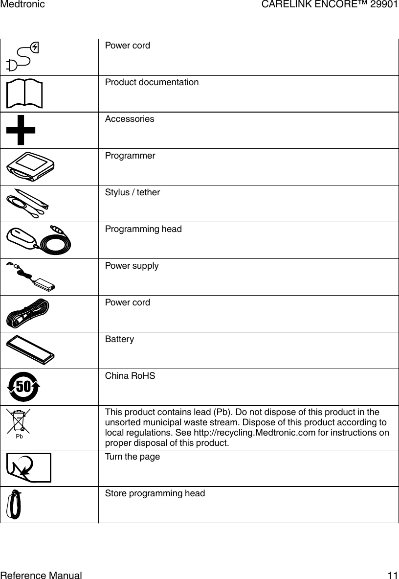
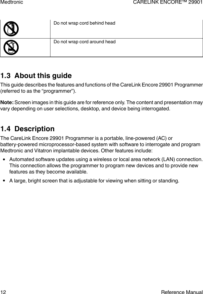
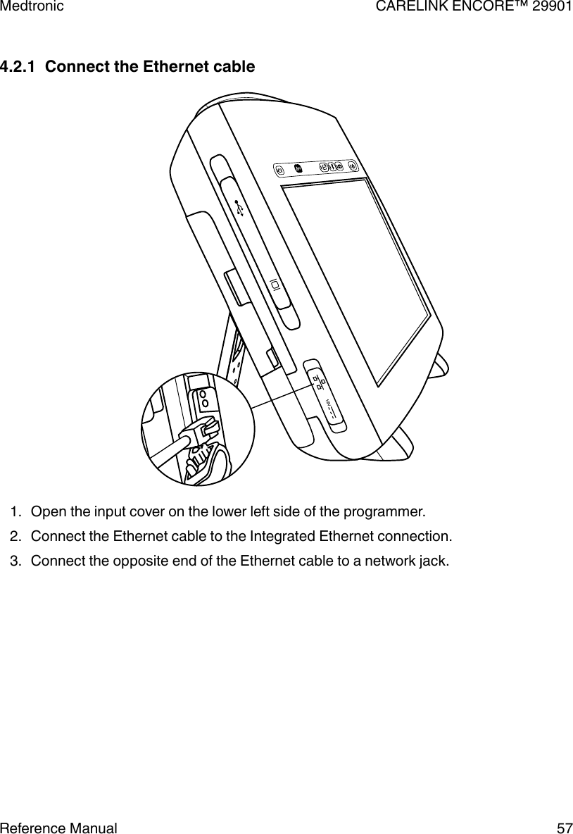
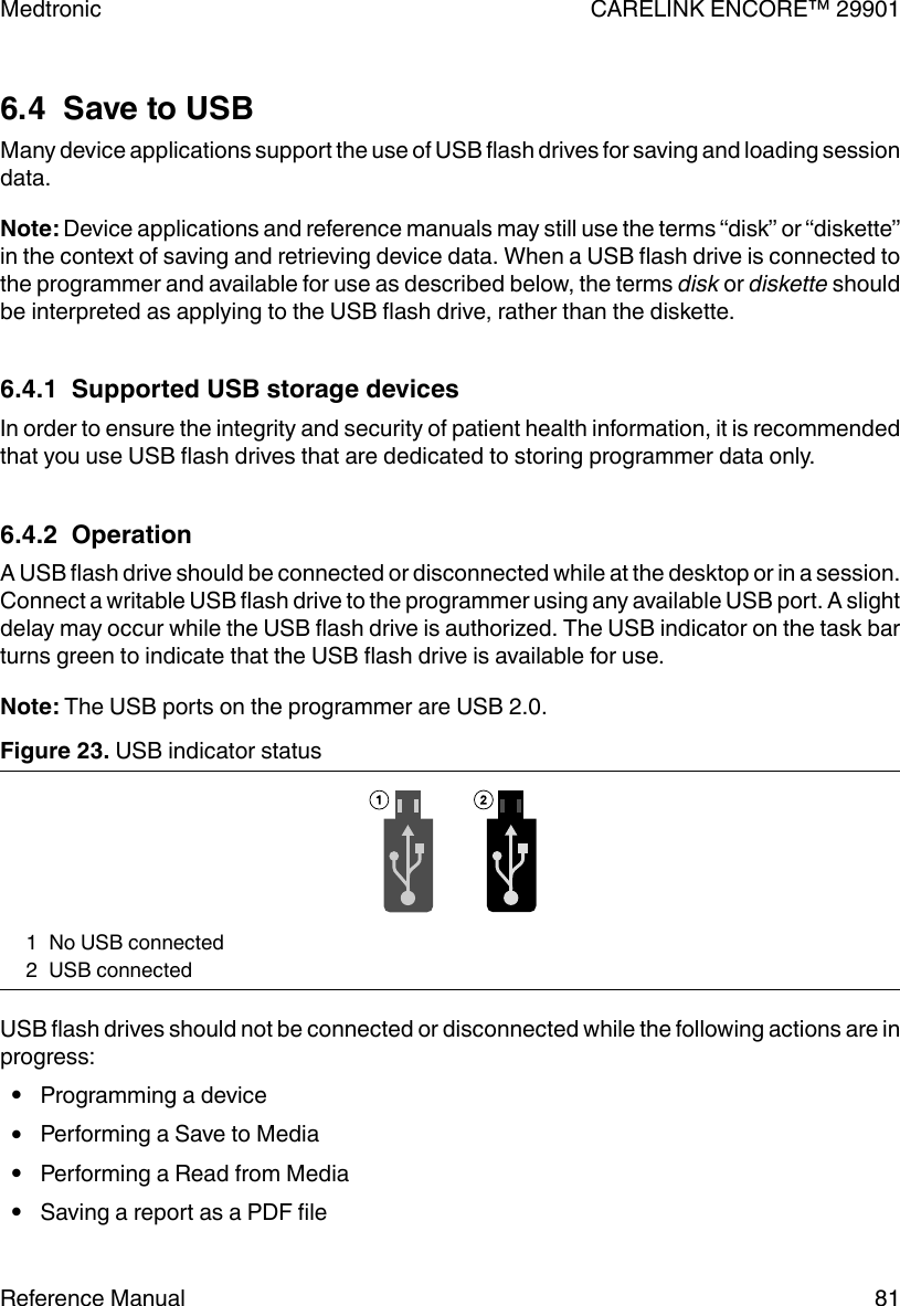
Medtronic 29901B 26901 User Manual MAPS ID 502334 012
Medtronic, Inc. 26901 MAPS ID 502334 012
UserManual.wiki
>
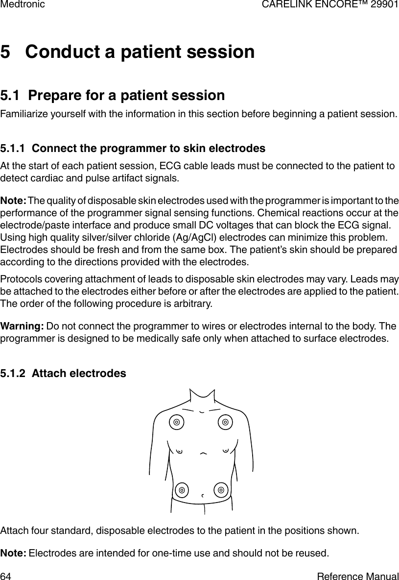
Medtronic
>
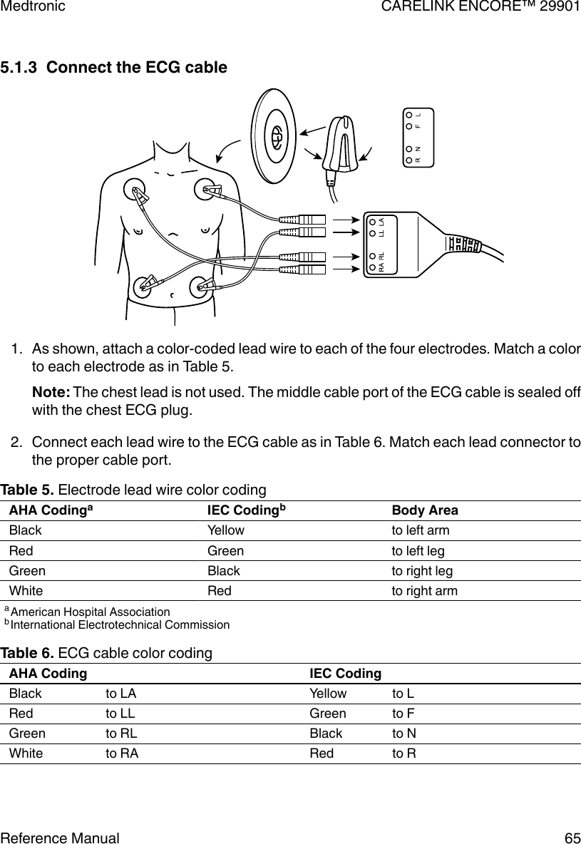
29901B User Manual
>
User Manual
Contents
1.
User Manual
2.
user manual
User Manual
Navigation menu
Upload a User Manual
Namespaces
Wiki Guide
HTML
PDF
Info
Views
User Manual
Discussion / Help
Navigation


![1.15 Obtain technical manualsMedtronic technical manuals, including the manual you are reading, are available in anumber of different formats from the Medtronic eManuals website listed on the back cover ofthis manual. The website offers real-time access to the latest version of manuals 24 hoursper day, seven days per week. Manuals can be viewed online, downloaded for viewing orprinting, or ordered from the website.All manuals are available online in English. Most manuals are also available in additionallanguages in online, CD-ROM, or paper format. New manuals are added to this site regularly.If you do not find the manual you want, contact your Medtronic or Vitatron representative.Your order for CD-ROM or printed versions of manuals ships from our facility within 24 hoursand should reach you within 3 business days. If you need a copy before the shipment arrives,download the manual and print it, or contact your Medtronic or Vitatron representative.1.15.1 Access the eManuals website1. Point your browser to the address listed on the back cover of this manual.2. Select location and language, and click [Continue].3. Select one or more manual languages, and click [Continue].To see lists of CRDM manuals, click the desired category on the left of the screen. You canalso search for manuals using a product name or model number.Medtronic CARELINK ENCORE™ 29901Reference Manual 23](https://usermanual.wiki/Medtronic/29901B.User-Manual/User-Guide-3101733-Page-23.png)
![2.5.4.2 Connect to a printer with Bluetooth (Bluetooth enabledprogrammers only)1. To connect to a printer with Bluetooth, turn on the programmer and turn the Bluetoothradio on for the programmer by pressing the Bluetooth button on the programmerbutton panel.Note: Your programmer may or may not have Bluetooth capability. If the Bluetoothbutton does not illuminate when pressed, your programmer is not enabled for Bluetoothprinting.2. Connect the printer power cord to an outlet and turn on the printer. Turn Bluetooth on forthe printer.Note: For more information on turning on Bluetooth for the printer, refer to the printermanual.3. Launch the Bluetooth configuration application by pressing the Bluetooth icon on theprogrammer taskbar.4. Press [Search] to search for available Bluetooth printers. If the Bluetooth radio isdisabled on the programmer, a message is displayed that you need to enable theBluetooth radio on the programmer by pressing the Bluetooth button on theprogrammer button panel.5. The Pair Bluetooth Printer window is displayed listing the available Bluetoothprinters. Select the printer you would like to pair with the programmer.Note: Only one printer can be paired with the programmer. To pair a new printer with theprogrammer, you must unpair the currently paired printer.6. Press [Pair]. Depending on your printer configuration, you will use one of the followingmethods to pair to the printer:●Enter the printer PIN on the programmer●Enter the Passkey (PIN) on the printer●Confirmation code sent to the printerMedtronic CARELINK ENCORE™ 2990140 Reference Manual](https://usermanual.wiki/Medtronic/29901B.User-Manual/User-Guide-3101733-Page-40.png)
![The programmer will automatically identify which method is needed to pair with aspecific printer.a. To pair using a PIN, enter the PIN code found on the printer or in the printer manual.The PIN can be between 1 and 16 characters. When you tap the PIN text field theon-screen keyboard is displayed. Enter the PIN with the on-screen keyboard in thePair Bluetooth Printer window. After the PIN has been entered, press [OK].b. To pair using a passkey, enter the PIN from the Pair Bluetooth Printer window onyour printer. The dialog automatically closes if the passkey is entered correctly.Note: The passkey is referred to as a “PIN”, but it is different from the PIN suppliedby the printer and entered on the programmer.c. To pair using a confirmation code, the programmer generates a code and sends itto the printer. The Pair Bluetooth Printer window displays the confirmation code.Confirm that the correct code was sent to the printer and press [Yes].7. The Pair Bluetooth Printer window shows a pairing activity indicator. When pairinghas completed successfully, the Configure Bluetooth window confirms that theprinter you selected is currently paired.8. Select the Print Queue icon.Note: Be sure to select the correct printer driver from the options listed when you selectthe Printer field on the Print Queue window. Make sure that the printer has paper. Youare now ready to use your programmer with the paired printer.Medtronic CARELINK ENCORE™ 29901Reference Manual 41](https://usermanual.wiki/Medtronic/29901B.User-Manual/User-Guide-3101733-Page-41.png)
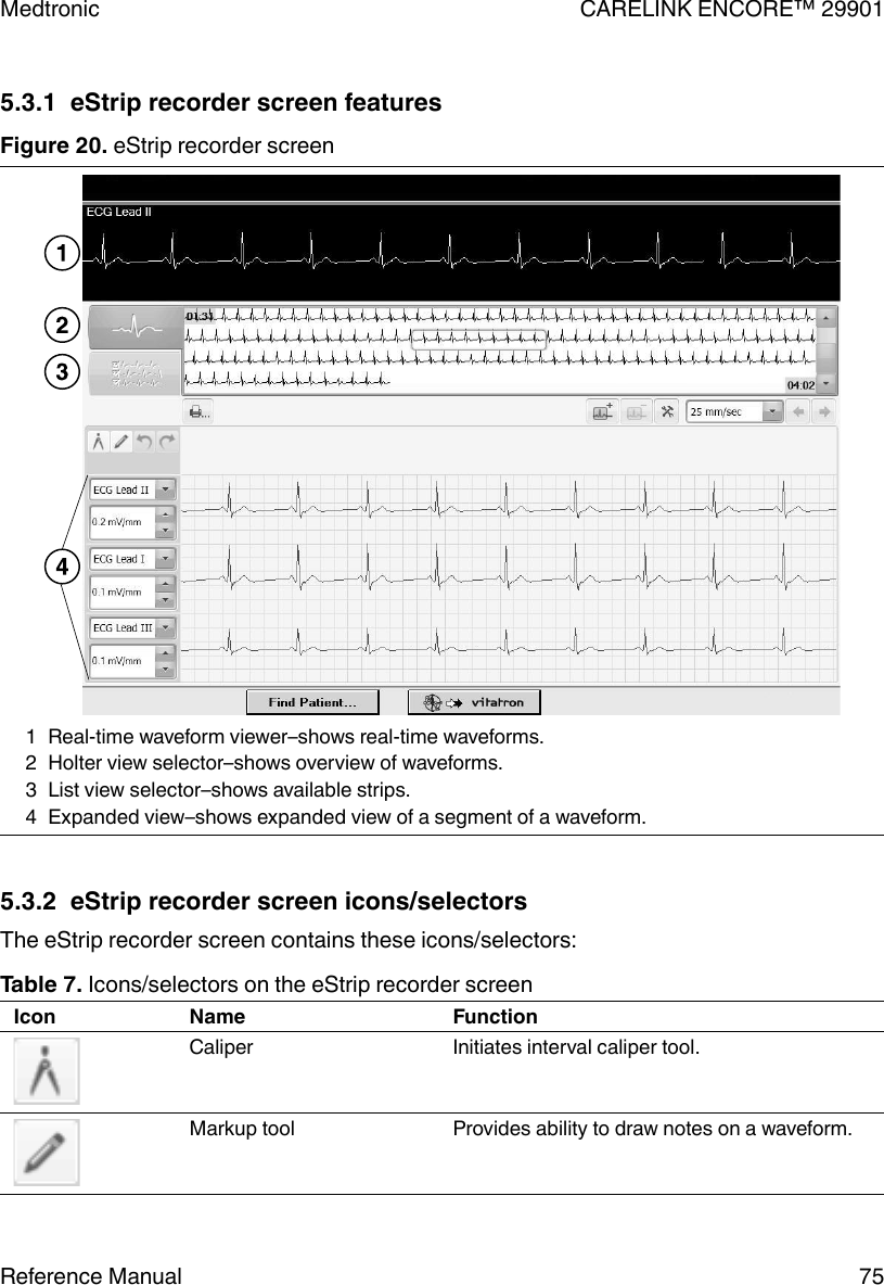
![Table 3. Task bar icons/indicators (continued)Icon Name FunctionElectronic Strip Chart(eStrip) selectorUsed to go to the Electronic Strip Chart (eStrip) recorderscreen.Device ApplicationselectorUsed to go to the Select Model screen on the programmerdesktop. During a patient session, the indicator box turnsblue to indicate that the programmer is on a device appli-cation screen.3.1.1.2 Status barBefore selecting a model, the status bar has no information. For specific information aboutthe status bar, refer to the reference guide for the implanted device. After model selection,the status bar may include:●The present pacing mode.●Test condition status.●The device model.3.1.1.3 Live Rhythm Monitor windowThis window is a partial view of the full-screen display of the ECG, and contains a Waveformadjustment bar that allows you to change the size of the waveform. You can expand thiswindow to full size by selecting the small square button in the upper-right corner of thewindow or by pressing [Adjust…].After model selection, Marker Channel and telemetered EGM waveform traces may beavailable.3.1.1.4 Task areaThe portion of the screen between the Live Rhythm Monitor window near the top of thescreen and the command bar at the bottom of the screen changes according to the task orfunction you select.3.1.1.5 Command barThe bar at the bottom of the screen shows the command buttons for automatically launchingthe proper software application and displaying the Vitatron Select Model screen. Forinformation on what command buttons are available after selecting a model, see thereference guide for the implanted device.Medtronic CARELINK ENCORE™ 2990144 Reference Manual](https://usermanual.wiki/Medtronic/29901B.User-Manual/User-Guide-3101733-Page-44.png)
![3.1.1.6 ButtonsButtons allow you to operate the programmer. You can “press” a button by touching it with thetip of the stylus or your finger.Buttons may directly execute a command, such as [Freeze], or they may open a window thatprompts another action. Buttons that open a window usually have a label ending with anellipsis, such as [Strips…] or [Adjust…].A procedure may instruct you to “press and hold” a button. Press the button and maintainpressure until it is time to “release” the button.When a button is inactive, it appears a lighter color and does not execute a command whenyou press it.3.1.1.7 Tool paletteThe collection of buttons and icons along the edge of the screen is referred to as the “toolpalette”. These buttons and icons are the controls you use to choose the task or functionscreen you want to display. Each of the icons acts like a button. Touch the icon to select it. Formore information, see Section 3.2. For information about the session tool palette, see thereference guide for the implanted device.3.2 About the Between Patient Sessions tool paletteThe Between Patient Sessions tool palette is on the Select Model screen. The Select Modelscreen appears before you select a model, when you turn the programmer on, and when youend a patient session.The tools that are available between patient sessions are described in Table 4.Note: When programming a Vitatron device, refer to the applicable reference guide forinformation about the tool palette.Table 4. Between Patient Sessions tool paletteTool Selecting the tool (button or icon)…Freezes a segment of the live rhythm display.Note: A frozen strip can be viewed, printed, or saved to PDF betweenpatient sessions. Markers and EGM traces are not present betweenpatient sessions.The [Strips…] button is not available between patient sessions. Savedrhythm strips can only be accessed during a patient session.Opens a window of options for adjusting the live rhythm display.Note: Additional adjustment options are present during a patient session.Medtronic CARELINK ENCORE™ 29901Reference Manual 45](https://usermanual.wiki/Medtronic/29901B.User-Manual/User-Guide-3101733-Page-45.png)
![Figure 12. Programmer Profile screen 3.6 Adjust programmer time and dateIf the time or date displayed and printed by the programmer is incorrect, use the followingprocedure to enter the correct settings. For Vitatron devices, see the applicable referenceguide.3.6.1 Set the time and date1. Press the Programmer icon then Time and Date.2. From the Programmer Time and Date screen, press the up or down button to increaseor decrease the value for the unit of time you want to change. Press and release thebutton for single unit changes or press and hold the button to effect greater changes.3. When all fields show the correct time and date, press [Apply]. Select another toolpalette icon to close the Programmer Time and Date windowMedtronic CARELINK ENCORE™ 2990148 Reference Manual](https://usermanual.wiki/Medtronic/29901B.User-Manual/User-Guide-3101733-Page-48.png)
![Figure 13. Programmer Time and Date screenNote: Time must be entered based on a 24-hour clock, with 00:00 being midnight, and12:00 being noon.3.7 Select audible tonesCertain events in the operation of the programmer result in an audible signal. The followingtones alert you to the success or failure of an action.●A two-tone beep (low-to-high) indicates confirmation of an Interrogate or a Programcommand.●A double low-tone beep indicates that an Interrogate, Program, or Emergencycommand was not confirmed. It can also indicate that the selected command cannot beexecuted.Note: For some devices, the tones may not be turned off. For more information, see thereference guide for the implanted device. For Vitatron devices, see the applicable referenceguide.3.7.1 Turn tones on or off1. Press the Programmer icon, and then select Preferences.2. From the Preferences screen, select [Audio ON] or [Audio OFF] as desired.Medtronic CARELINK ENCORE™ 29901Reference Manual 49](https://usermanual.wiki/Medtronic/29901B.User-Manual/User-Guide-3101733-Page-49.png)
![Figure 15. Software on This Programmer screen Note: If the model that you require is not displayed, the software to support that model is notcurrently loaded on the programmer. Contact your Medtronic or Vitatron representative.3.9 Select other softwareIn addition to the standard application software, there are some programmers that haveother applications installed. These applications may include supplemental software orsoftware used in clinical studies for research. If you have other software installed, you mayaccess the software, using the following procedure.1. Press the Programmer icon, and then select Other Software.2. When the programmer displays the list of available software, select the application andpress [Start].3.10 Remove other software applicationsProgrammers with other software installed, such as supplemental software or those used inclinical studies for research, may allow the applications to be removed from the programmerdesktop. If you have software installed that permits removal, you may remove it using thefollowing procedure.Medtronic CARELINK ENCORE™ 29901Reference Manual 51](https://usermanual.wiki/Medtronic/29901B.User-Manual/User-Guide-3101733-Page-51.png)
![1. Press the Programmer icon, and then select Software.2. Press [Uninstall Software…].3. When the programmer displays the list of removable software, select the application tobe removed, and then press [Uninstall].4. Select the check box next to the acknowledgment statement, and then press[Continue].5. The software is removed, and the programmer reboots.6. Verify that the software has been removed.3.11 Improve the detection of pacing artifactsThe Artifact Detection function allows you to improve the detection of pacing artifacts wheninterference causes either false artifacts or no artifacts to appear on the patient’s ECG.Pacing artifacts are displayed on the patient’s ECG when the artifact detection option (ShowArtifacts) has been enabled.To determine if this feature is applicable, see the reference guide for the implanted device.3.11.1 Enable artifact detection1. Press the Programmer icon, and then select Artifact Detection.2. Make sure the current settings include ARTIFACT DISPLAY IS ON.3. Make sure the current settings include MV FILTER IS ON.3.12 Start the Demonstrations optionThe demonstrations option allows you to run a demonstration program on the programmer.For Vitatron devices, see the applicable reference guide.Note: Device applications and reference manuals may still refer to using the “demonstrationdisk” or “demonstration diskette” to run a demonstration program. The need for ademonstration diskette to access demonstration mode is no longer required. All referencesto a demonstration diskette can be ignored. All demonstration mode features are accessiblewith or without a demonstration diskette.Medtronic CARELINK ENCORE™ 2990152 Reference Manual](https://usermanual.wiki/Medtronic/29901B.User-Manual/User-Guide-3101733-Page-52.png)
![3.12.1 Access demonstrations1. Press the Programmer icon, and then select Demonstrations.2. From the Demonstration Model Selection screen, select the desired View option to listthe available demonstration programs.3. Select the desired demonstration program and press [Start] followed by [Continue].3.13 Configure network using the Network Configurationwindow3.13.1 About the Network Configuration windowFigure 16. Network Configuration windowThe Network Configuration window is used to set up connections to the Software DistributionNetwork (SDN) and SessionSync using wireless and Ethernet conections. The first time theNetwork Configuration window is accessed the Clinic Name field is empty. For SessionSync,the SessionSync Gateway Address field also needs to be filled in. Until the Clinic Name andSessionSync Gateway Address fields are filled in, the [OK] is disabled. After you click [OK],the values are saved and the dialog closes. The next time the dialog is opened, the fields willbe populated with the previously saved values and the [OK] will be enabled. If you manuallyclear one or more fields, the [OK] is disabled and the “Some fields empty…“ message isdisplayed in the entry error text box.Medtronic CARELINK ENCORE™ 29901Reference Manual 53](https://usermanual.wiki/Medtronic/29901B.User-Manual/User-Guide-3101733-Page-53.png)
![3.13.2 Configure network connection1. Press the Network Configuration icon on the task bar. The programmer displays theNetwork Configuration window.2. Select the radio button for SDN or SessionSync.Note: If you selected SessionSync, you also need to enter the SessionSync GatewayAddress. The field is visible only after selecting SessionSync.3. Enter the Clinic Name.4. Enter the Network Name (SSID). To select the Network Name from the AvailableNetworks, see Section 3.13.3.5. Select Network Authentication from the drop-down list.6. Enter Network Key.7. Re-enter the Network Key in the Confirm Network Key field.8. Press [OK].3.13.3 View available networksNote: Wi-Fi must be enabled to view available networks. Press the Wi-Fi button to enableWi-Fi. If there is an Ethernet connection when the Network Configuration window islaunched, a Wi-Fi connection cannot be established.1. Press [View Available Networks]. The View Available Networks dialog displays with nonetwork selected and the [OK] button disabled. When you select a network, the [OK]button is enabled.Note: If there are no available networks, the View Available Networks dialog will nothave any networks listed. If there are more than 3 available networks, the first three arevisible and a vertical scroll bar is displayed.2. After you select the network and press the [OK] button, the Network Name (SSID) fielddisplays the network you selected in the Network Configuration dialog.3.13.4 Test the network connectionAfter connecting to the network, you can test the connection to make sure the programmeris connected properly. From the Network Configuration window, press [Test NetworkConnection]. The Test Output: field displays the results of the test and is scrollable using theup and down arrows on the right.Medtronic CARELINK ENCORE™ 2990154 Reference Manual](https://usermanual.wiki/Medtronic/29901B.User-Manual/User-Guide-3101733-Page-54.png)
![Use the Test Network Connection feature if your programmer is having difficulty connectingto your clinic’s network. Contact Medtronic Technical Support if you need assistance ininterpreting results.3.13.5 Save network connection test results to media1. Connect a USB flash drive to the programmer.2. Press [Save To Media].Note: This button is available only if the Test Network Connection tests have been run.The programmer displays the Save to Media dialog.3. Press [Save].A text file (NtwkTestOutput.log) containing the test results is saved to the USB flash drive.Download the file to a compatible computer for viewing and/or transfer to Medtronicpersonnel.Medtronic CARELINK ENCORE™ 29901Reference Manual 55](https://usermanual.wiki/Medtronic/29901B.User-Manual/User-Guide-3101733-Page-55.png)
![4.2.2 How to connect to the SDN using a wired network connection1. Press the Programmer icon, and then select Software.The programmer displays the Software on This Programmer screen and lists thesoftware already installed on the programmer. For each model, the screen displays thesoftware version.Note: The SDN cannot be accessed from Vitatron screens. Change to the MedtronicSelect Model screen.2. Press [Install from Medtronic…].3. Follow the prompts that are displayed to start the download.orPress [Cancel]. The download process is canceled and the programmer redisplays theSoftware on This Programmer screen.Medtronic CARELINK ENCORE™ 2990158 Reference Manual](https://usermanual.wiki/Medtronic/29901B.User-Manual/User-Guide-3101733-Page-58.png)
![4. The programmer displays the Scheduled Software Update screen.Choose to either start the download at a particular time by selecting a time from theScheduled Update Time pull-down menu, or begin the download as soon as possibleby pressing [Start].5. The Scheduled Software Update window displays a countdown window showing howmuch time remains until the download begins. Press [Start Now] to override thecountdown or press [Cancel] to interrupt the countdown and the download request andreturn to the Software on This Programmer screen.Medtronic CARELINK ENCORE™ 29901Reference Manual 59](https://usermanual.wiki/Medtronic/29901B.User-Manual/User-Guide-3101733-Page-59.png)
![6. The programmer displays a list of software that will download and install.Note: Individual software cannot be selected or rejected.You may press [Stop] at anytime and resume the download at a future time.7. When the download is complete, the programmer disconnects from the SDN,automatically reboots, and displays a screen listing the software that was downloaded.8. To obtain technical manuals for the new software, see Section 1.15.9. Press the Select Model icon. The programmer is then available for patient use.Note: The first time the newly downloaded software is accessed, some additionalinstallation steps may be completed but these steps are automatic and no user interventionis requiredMedtronic CARELINK ENCORE™ 2990160 Reference Manual](https://usermanual.wiki/Medtronic/29901B.User-Manual/User-Guide-3101733-Page-60.png)
![4.3 Connect to the SDN using a wireless networkconnectionNote: Before you begin, make sure that the wireless connection is correctly configured. Formore information, see Section 3.13.4.3.1 How to connect to the SDN using a wireless network connection1. Press the Programmer icon, and then select Software.The programmer displays the Software on This Programmer screen and lists thesoftware already installed on the programmer. For each model, the screen displays thesoftware version.Note: The SDN cannot be accessed from Vitatron screens. Change to the MedtronicSelect Model screen.2. Press [Install from Medtronic…].3. Follow the prompts that are displayed to start the download.orPress [Cancel] if you do not agree to the terms. The download process is canceled andthe programmer redisplays the Software on This Programmer screen.Medtronic CARELINK ENCORE™ 29901Reference Manual 61](https://usermanual.wiki/Medtronic/29901B.User-Manual/User-Guide-3101733-Page-61.png)
![4. The programmer displays the Scheduled Software Update screen. Press [Configure].5. On the Scheduled Software Update screen, either choose to start the download at aparticular time by selecting a time from the pull-down menu, or begin the download assoon as possible by pressing [Start]. The programmer shuts down and displays awindow telling you to please wait.6. The Scheduled Software Update window displays a countdown window showing howmuch time remains until the download begins. Press [Start Now] to override thecountdown or press [Cancel] to interrupt the countdown and the download request andreturn to the Software on This Programmer screen.Medtronic CARELINK ENCORE™ 2990162 Reference Manual](https://usermanual.wiki/Medtronic/29901B.User-Manual/User-Guide-3101733-Page-62.png)
![7. The programmer displays a list of software that will download and install.Note: Individual software cannot be selected or rejected.You may press [Stop] at anytime and resume the download at a future time.8. When the download is complete, the programmer disconnects from the SDN,automatically reboots, and displays a screen listing the software that was downloaded.9. To obtain technical manuals for the new software, see Section 1.15.10. Press the Select Model icon. The programmer is then available for patient use.Note: The first time the newly downloaded software is accessed, some additionalinstallation steps may be completed but these steps are automatic and no user interventionis required.Medtronic CARELINK ENCORE™ 29901Reference Manual 63](https://usermanual.wiki/Medtronic/29901B.User-Manual/User-Guide-3101733-Page-63.png)
![When the Find Patient screen is displayed, you may begin a patient session.Place the programming head over the patient’s device and hold it steady. For most devices,the programmer identifies the device model and automatically starts up the proper softwareapplication. If a device cannot be automatically identified, the programmer displays amessage at the top of the Find Patient screen. Perform one of the following steps, dependingon the message instructions:●Press [Cancel] and manually select the software application from the Select Modelscreen.●Press [Cancel] and then press the Vitatron/Medtronic switch button to go to the Vitatrondesktop.●If the message indicates that the needed software application has not been installed,contact your Medtronic or Vitatron representative.Medtronic CARELINK ENCORE™ 2990172 Reference Manual](https://usermanual.wiki/Medtronic/29901B.User-Manual/User-Guide-3101733-Page-72.png)
![5.2.2.2 Select Model screenA patient session may also begin from the Select Model screen. The Select Model screenappears after one of the following actions:●Shortly after the programmer has been turned on●After you end a patient sessionIf the Select Model screen is not displayed, use the stylus to press the Select Model icon. Ifthe Select Model icon is not displayed, a patient session is in progress. You must end thatsession before starting a new session.If you are between patient sessions, you can access other screens by using the icons andbuttons described in Section 3.2.If the Select Model screen does not look like this example and you see a different button inthe command bar, press the Vitatron/Medtronic switch button to display this screen.If the device is a Vitatron device and it is not listed on the Select Model screen, seethe Vitatron Software Programming Guide.Position the programming head over the patient’s device and hold it steady. Press [FindPatient] shown on the Medtronic desktop or manually select the device from the displayedlist of devices and press [Start].Medtronic CARELINK ENCORE™ 29901Reference Manual 73](https://usermanual.wiki/Medtronic/29901B.User-Manual/User-Guide-3101733-Page-73.png)
![5.3.4 Change the length of a strip1. Select a strip.2. Press and hold the border of the strip.3. Drag the border of the strip to make it longer or shorter.5.3.5 Measure intervals using calipers1. Select a strip.2. Press the Caliper icon.3. Press the arrow icon on the bottom right corner of the strip to walk the calipers.4. To save caliper measurement to strip, press the tack icon.5.3.6 Change the name of a strip1. Press the List View button to display available strips.2. Press the name of the strip in the expanded view on the bottom half of the screen.3. Change the name of the selected strip by either typing a new name when the keyboarddisplays or selecting a name from the library by clicking the down arrows next to thename field.4. Press [OK].5.3.7 Create test strip report from the eStrip recorder1. Run a test in the device application.2. Open the eStrip recorder from the Task bar.3. Press the List View button to display available strips.4. Select the strip or strips you want to use to create a report.5. Press the Print icon.6. From the Reports – Strip Chart window, press [Print Now] to print the report or [Save toPDF File] to save the report to PDF. You can select the number of copies to print or pressSelect Strips to change which strips will be included in the report.Note: To save a report to PDF, you must have a USB flash drive connected to theprogrammer where the PDF will be saved to.Medtronic CARELINK ENCORE™ 29901Reference Manual 77](https://usermanual.wiki/Medtronic/29901B.User-Manual/User-Guide-3101733-Page-77.png)
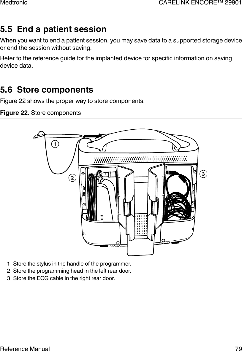
![5.4 Emergency VVI buttonThe red emergency VVI button on the programmer button panel provides immediate accessfor emergency VVI pacing during a patient session. Pressing the red emergency VVI buttondisplays the emergency screen options and delivers VVI pacing.Figure 21. Programmer button panel1 Red emergency VVI buttonSpecific parameter values for emergency VVI pacing are determined by each deviceapplication. The red emergency VVI button may be available after a system error.Note: For all ICD applications, the [Emergency] button is also implemented in the softwareand is available from the display screen. For more information on the [Emergency] buttonavailable from the display screen, see the reference guide for the implanted device.5.4.1 Deliver emergency bradycardia pacingTo initiate emergency pacing, correctly position the programming head over the implanteddevice and press the red emergency VVI button. A message confirms programming, andemergency VVI operation begins.5.4.2 Deliver emergency tachyarrhythmia therapyTo deliver therapy, press the red emergency VVI button to display the emergency screen onthe programmer and press the on-screen [Deliver] button.For complete instructions regarding the use of the [Deliver] button for specific applications,see the appropriate device Reference Guide, System Reference Guide, or ClinicianManual.Medtronic CARELINK ENCORE™ 2990178 Reference Manual](https://usermanual.wiki/Medtronic/29901B.User-Manual/User-Guide-3101733-Page-78.png)
![6 Manage session data and reports6.1 Session dataPatient session data may be saved to a USB flash drive.6.2 ReportsDepending on the implanted device model, various types of reports can be created. Refer tothe reference guide for the implanted device for specific information on report types andcontents. During an active session, reports may be printed, or saved as PDF files on a USBflash drive. Reports held for later printing may be printed while at the desktop or whenreturning to a session. Reports might not be available for later printing from the desktop,depending on the device application and on the current print queue deletion schedule. Formore information, see Section 6.9.6.3 Save to a PDF filePrintable reports, frozen strips, and other data may be saved to a PDF file. A PDF file is anelectronic version of a printed document; therefore, the feature is accessible under theprinting commands.To save to a PDF file, perform the following steps:1. Open or create the report or file.2. Press [Print…] or [Print Options…] to display the Print – Options dialog box.Note: If the Print – Options dialog box does not display, open Preferences, and thenselect the Printing: Pop up these options when any print button is selected checkbox.3. From the list of supported printers, select the Save to PDF File option. The report issaved to an attached USB flash drive. For more information on saving to USB, seeSection 6.4.Medtronic CARELINK ENCORE™ 2990180 Reference Manual](https://usermanual.wiki/Medtronic/29901B.User-Manual/User-Guide-3101733-Page-80.png)
![6.6 View reports on the programmer using PDF ViewerThe PDF Viewer allows you to view and print PDF reports previously saved on a USB flashdrive.1. Connect a USB flash drive with saved PDF reports.2. Select the PDF Viewer in the taskbar. The list of the available PDF files on the USB flashdrive is displayed in the left panel.3. Click the file name to open a preview of the PDF. To open the PDF, press [Opendocument] or double-click the PDF file namePDF files on the USB flash drive other than previously-saved PDF reports are also viewablewith the PDF Viewer.●You can use the toolbar at the top of the PDF to go to a specific page, increase ordecrease the size of the document, or search within the PDF.●To hide the list of PDFs to provide a larger viewing area for the PDF, press [Hide] in thelower left corner of the PDF viewer. To restore the list, press [Show].●To print a PDF, with a report open in the PDF Viewer, press the Print icon.6.7 Viewing and printing PDF files on a computerInsert the USB flash drive containing the reports into a computer equipped to display filesthat are in PDF format.Due to computer and software variations, some PDF files may not be displayed properlywhen viewed on a computer monitor.The use of Adobe Reader 9 or later is recommended. Adjusting the following settings mayreduce or eliminate display imperfections:●Replace document colors with white page background and black text (in Adobe Reader9, select: Edit > Preferences > Accessibility > Replace Document Colors > CustomColor)●Deselect the option to enhance thin lines (in Adobe Reader 9, select: Edit > Preferences> Page Display)Imperfections that may be seen on screen:●On graphs that contain rectangles drawn with thin lines, e.g., bar graphs, the thin linesmay not be displayed at various zoom levels.●On Pacing and Tachy Trigger Episode reports, unfilled circles may be displayed as filledcircles.Medtronic CARELINK ENCORE™ 29901Reference Manual 83](https://usermanual.wiki/Medtronic/29901B.User-Manual/User-Guide-3101733-Page-83.png)
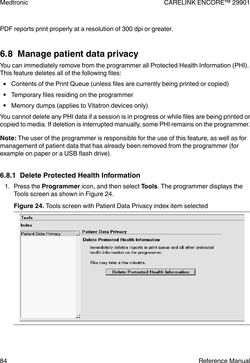
![2. Press [Delete Protected Health Information]. The programmer displays the dialog boxas shown in Figure 25.Figure 25. Delete Protected Health Information confirmation dialog box 3. Press [Delete] to continue.One of the following events may occur:The programmer displays an “In progress…” dialog box as shown in Figure 26. Deletionmay last several minutes, depending on the amount of data to delete.Figure 26. In progress dialog boxIf there are SessionSync files on the programmer that have not been transferred yet, theprogrammer displays a message indicating that there are SessionSync files waiting tobe transferred, as shown in Figure 27. Press [Delete] to delete the SessionSync files or[Cancel] to wait until the SessionSync files have transferred.Figure 27. SessionSync files waiting dialog boxMedtronic CARELINK ENCORE™ 29901Reference Manual 85](https://usermanual.wiki/Medtronic/29901B.User-Manual/User-Guide-3101733-Page-85.png)
![If there are reports currently printing, the programmer displays a message directing youto wait until printing is complete, as shown in Figure 28. Press [Close].Figure 28. Printing in progress dialog box 4. If pressing [Delete] in Step 3 resulted in protected health information deletion, theprogrammer displays a message stating that deletion was successful, as shown inFigure 29. Press [Close].Figure 29. Deletion successful dialog boxOr,If the programmer is unable to complete deletion of files, it displays a message statingthat there was an error and that some data may remain on the programmer, as shown inFigure 30. Press [Close]. Contact Medtronic Technical Support if the message recurs.Figure 30. Error deleting files dialog box Medtronic CARELINK ENCORE™ 2990186 Reference Manual](https://usermanual.wiki/Medtronic/29901B.User-Manual/User-Guide-3101733-Page-86.png)
![6.9.2 Delete a report immediatelyTo delete a report immediately, directly access it from the print queue and press [Delete].Medtronic CARELINK ENCORE™ 2990188 Reference Manual](https://usermanual.wiki/Medtronic/29901B.User-Manual/User-Guide-3101733-Page-88.png)
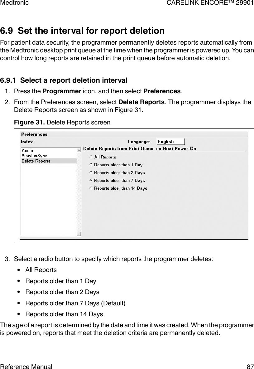
![7 SessionSync (Optional)7.1 About SessionSyncSessionSync is an optionally installed feature that provides network connectivity betweenthe programmer and the Medtronic Paceart data management system. Using your clinic’snetwork, the programmer can send downloaded device data through SessionSync to thedata management system.The SessionSync status icon and the SessionSync status screen provide information on theconnection status of the programmer to the data management system.You must configure the programmer network settings to allow for this data transfer.7.2 Enable and disable SessionSync1. Select Programmer > Preferences.2. Select SessionSync from the Index menu.3. Select [Enabled] to enable SessionSync or Select [Disabled] to disable SessionSync.Note: The SessionSync icon in the task bar will be grayed out when the feature is disabled.SessionSync functions are not available within a patient session unless you have enabledthis feature prior to starting a patient session.Figure 32. Preferences screen with Session Sync selectedMedtronic CARELINK ENCORE™ 29901Reference Manual 89](https://usermanual.wiki/Medtronic/29901B.User-Manual/User-Guide-3101733-Page-89.png)
![Table 8. SessionSync Status icon states (continued)Part of SessionSync Status Icon Color What the color indicatesConnection Not visible No valid connection exists between theprogrammer and the data managementsystemGreen Valid connection exists between the pro-grammer and the data management sys-temRed circlewith a linethrough itDevice application in use does not sup-port SessionSyncData Management System Gray No session data has been transferred tothe data management systemBlue All session data has been successfullytransferred to the data management sys-tem7.4 Use Automatic SessionSyncAutomatic SessionSync allows you to perform a SessionSync automatically at the end of apatient session. This feature is available for all SessionSync enabled devices.7.4.1 Save the patient session with Manual SessionSync1. Press the Session icon.2. Select SessionSync….3. The SessionSync - Saving Session Data On Programmer window is opened and forsome devices an interrogation is automatically started. The SessionSync - SavingSession Data On Programmer window shows the progress of the save. TheProgrammer side of the SessionSync Status icon turns blue after the data has beensaved on the Programmer hard disk. If the subsequent transfer is successful, the datamanagement system side of the SessionSync Status icon turns blue.7.4.2 End a patient session with Automatic SessionSync enabled1. Press [End Session…]. If an interrogation is required before the SessionSync datatransfer, the Interrogation Required window is displayed.2. Verify that the Automatic SessionSync box is checked, and then press [End Now].Medtronic CARELINK ENCORE™ 29901Reference Manual 91](https://usermanual.wiki/Medtronic/29901B.User-Manual/User-Guide-3101733-Page-91.png)
![3. The SessionSync - Saving Session Data On Programmer window is opened. For somedevices, an interrogation is automatically started. The SessionSync - Saving SessionData On Programmer window shows the progress of the save. The programmer side ofthe SessionSync Status icon turns blue after the data has been saved on theprogrammer hard disk. If the subsequent transfer is successful, the data managementsystem side of the SessionSync Status icon turns blue.7.5 Use Manual SessionSync for supported devicesManual SessionSync allows you to send interrogated data to the Paceart data managementsystem without ending the patient session on the Programmer.Manual SessionSync is not available for all SessionSync supported devices. If manualSessionSync is available for a device, the SessionSync… option appears in the Sessionmenu.7.6 SessionSync error message descriptionsYou may receive error or information messages at different times in the SessionSyncprocess. For a list of error messages, see Table 9. If you have any issues with theprogrammer contact Medtronic Technical Support at the telephone number on the backcover of this manual.Table 9. SessionSync error messagesError Message What it meansData Transfer Failed A device communication error has occurred during the interrog-ation and you have cancelled out of the interrogation window. Thesession data has not been saved on the programmer hard disk.Do one of the following:Press [Retry] to retry the operation.Press [Cancel] to close the window.Ending a Session without Auto-matic SessionSyncYou have cleared the Automatic SessionSync check box on theEnd Session window before pressing the [End Now] button.Interrogation Required You must conduct an interrogation before starting a SessionSyncdata transfer for this device.Press [OK] to close the window.Medtronic CARELINK ENCORE™ 2990192 Reference Manual](https://usermanual.wiki/Medtronic/29901B.User-Manual/User-Guide-3101733-Page-92.png)
![Table 9. SessionSync error messages (continued)Error Message What it meansInterrogate - Unsuccessful The programmer cannot interrogate the device. You must reposi-tion the programming head.Do one of the following:Press [Retry] or [Continue] after repositioning the programminghead.Press [Cancel] to close the window.Unable to Save Session Data The session data cannot be saved on the programmer hard disk.Do one of the following:Press [Save to Media] or [Save Session] to save the session datato media.Press [End Now] to end the session without saving the devicedata.Press [Cancel] to close the window without saving the devicedata.7.7 View SessionSync Status screenThe SessionSync Status screen displays information on the data files being transferred tothe data management system using SessionSync. Each message includes the date, time,and event information for the associated SessionSync event.7.8 Update SessionSync statusMedtronic CARELINK ENCORE™ 29901Reference Manual 93](https://usermanual.wiki/Medtronic/29901B.User-Manual/User-Guide-3101733-Page-93.png)
![1. Press the Programmer icon, and then select SessionSync Status.2. Press [Update Status].Note: SessionSync status does not dynamically update when the window is open. Toupdate, press [Update Status].Medtronic CARELINK ENCORE™ 2990194 Reference Manual](https://usermanual.wiki/Medtronic/29901B.User-Manual/User-Guide-3101733-Page-94.png)


![IndexAAC power input ........................ 25Adjust button .......................... 45[Adjust…] button ....................... 45Adobe settings ........................ 83AHA codingelectrodes ........................ 65annotationsMarker Channel ..................... 44parameter programming ................ 44artifact detection ....................... 52Auto Identify .......................... 73see also Find PatientBbattery ........................... 25, 31charge .......................... 35status ........................... 35Bluetooth .......................... 40, 43buttonsAdjust ........................... 45[Adjust…] ......................... 45Auto Identify ....................... 73Bluetooth ......................... 28[Deliver] .......................... 78description ........................ 45Electronic Strip Chart (eStrip) ............. 28[Emergency] ....................... 78Emergency VVI ..................... 28Find Patient ..................... 44, 73[Freeze] .......................... 45inactive .......................... 46Power ......................... 28, 33RFID ........................... 28Strips ........................... 45[Strips…] ......................... 45Vitatron/Medtronic switch ............... 73VVI ............................. 78Wi-Fi ........................... 28see also Find Patientsee also iconsCcommand bar, programmer ................. 44componentsstoring ........................... 79connectorECG cable ........................ 27programming head ................... 27Contraindications ....................... 13Ddate and timesetting ........................... 48Declaration of Conformity .................. 18[Deliver] button ........................ 78demonstrations option .................... 52dimensions, programmer .................. 98display screenfeatures of screen .................... 42EECG ............................... 20cable ........................... 25cable connections .................... 34functions on the programmer ............. 20electrodesAHA coding ....................... 65attaching ....................... 64, 65IEC coding ........................ 65[Emergency] button ...................... 78Emergency VVI button .................... 28environmental precautionsdisposal of programmer .............. 9, 11while using programmer ................ 17Ethernet cable ......................... 25connecting ........................ 57Ffeaturesprogrammer ....................... 12Federal Communications Commission (FCC) ...... 19Find Patient button ...................... 73Find Patient screen ...................... 71[Freeze] button ........................ 45Hhardware informationprogrammer ....................... 47humidity limitsprogrammer ....................... 98Medtronic CARELINK ENCORE™ 29901106 Reference Manual](https://usermanual.wiki/Medtronic/29901B.User-Manual/User-Guide-3101733-Page-106.png)
![reportsdeleting .......................... 87saving to PDF ...................... 80saving to USB ...................... 81viewing .......................... 82RFID button .......................... 28RTTE Directivedevice conformance .................. 18SscreenFind Patient ....................... 71Select Model ....................... 73selecting the device model ................. 73serial numbers ......................... 47SessionSync ........................ 43, 89automatic ......................... 91color indicators ..................... 90components of status icon ............... 90enabling and disabling ................. 89error messages ..................... 92manual .......................... 92status icon ........................ 90viewing status of ..................... 93skin electrodes ...................... 64, 65see also electrodessoftware requirements .................... 22specificationsprinter ........................... 97programmer ....................... 97standards, compliance .................... 97status bar, programmer ................... 44storage humidityprogrammer ....................... 98storage temperatureprogrammer ....................... 98Strips button .......................... 45[Strips…] button ........................ 45stylusstoring ........................... 29using ........................... 66system preferences ...................... 49Ttask bar, programmer ..................... 43telemetryfunctions ......................... 20temperature limitsprogrammer ....................... 98time and datesetting ........................... 48traces, waveform ....................... 44UUSBsaving to ......................... 81storage devices ..................... 81VVitatron/Medtronic switch button .............. 73VVI button ........................... 78Wwarningsprogrammer ....................... 13warranty informationprogrammer ...................... 100waveform traces ........................ 44websiteaccessing technical manuals ............. 23weight, programmer ..................... 98Wi-Fi .............................. 28wireless ............................. 61Medtronic CARELINK ENCORE™ 29901108 Reference Manual](https://usermanual.wiki/Medtronic/29901B.User-Manual/User-Guide-3101733-Page-108.png)