Medtronic 4NR003 4NR003 User Manual
Medtronic, Inc. 4NR003
User Manual

EXTERNAL NEUROSTIMULATOR
4NR003
User manual
c
Rx only
CAUTION: Investigational device. Limited by Federal (or United
States) law to investigational use.
CAUTION: This device is intended exclusively for clinical investigations.
2016‐1008‐01 English3
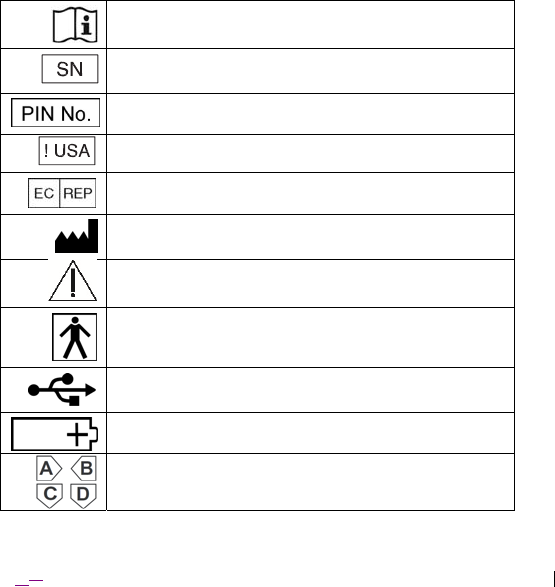
Explanation of symbols on product or package labeling
Refer to the appropriate product for symbols that apply.
Consult instructions for use
Serial number
Pin number
For USA audiences only
Authorized representative in the European community
Manufacturer
Warning
Type BF applied part (EN 60601-1)
Universal Serial Bus (USB) 2.0 port
Battery
Omnetics (A29100-065) connector interface ports

English4 2016‐0810‐01
MedtronicTM is a trademark of Medtronic, Inc., registered in the US and other countries.
Third party brands are trademarks of their respective owners.
FCC Information
The following is communications regulation information on the Model 4NR003 External
Neurostimulator.
FCC ID: LF54NR003
This device complies with Part 15 of the FCC Rules. Operation is subject to the
following two conditions: (1) This device may not cause harmful interference, and (2)
this device must
accept any interference received, including interference that may
cause undesired operation.
IMPORTANT: Changes or modifications to this product not authorized by
Medtronic, Inc., could void the FCC Certification and negate your authority to
operate this product.
European Union Compliance
Conformité Européenne
(European Conformity)
Medtronic declares that this product is in conformity with the essential requirements
of
Directive 93/42/EEC on Medical Devices.
For additional information, contact the appropriate Medtronic representative listed on
the inside back cover of this manual.
This product operates at 2.4 GHz with an RF output power of less than 10mW e.i.r.p.
2016‐1008‐01 English5
Table of contents
Description 7
Package contents 7
Accessories 7
Device specifications 8
Interactions with other medical equipment 1615
Electromagnetic compatibility declaration 1817
Means of operator and patient protection 2625
Instructions for use 2726
Using the ENS during a research study 2928
Replacing the ENS batteries 3735
Troubleshooting 3937
Device care and storage 4139
Cleaning the ENS 4240
Safety and technical checks 4341
NOTE:
Algorithm Developers: Refer to instructions shipped separately with the Odin
Research System Interface Software for specifications in programmatically
interfacing with the neurostimulator.
Managing Physician and Team: Consult the Odin Configuration Tool Instructions
for Use, shipped separately with the Odin Research System Interface Software,
and the research study protocol for which this neurostimulator is being used, for
details on configuring and running an experiment using the neurostimulator.

English6 2016‐0810‐01

2016‐1008‐01 English7
Description
The Medtronic Model 4NR003 External Neurostimulator (ENS) is designed to
provide concurrent sensing and stimulation of the brain as part of an investigational
research study in an acute clinical setting. It is intended for use only under the
supervision of trained medical personnel.
Package contents
▪ ENS
▪ Product literature
Accessories
▪ None

English8 2016‐0810‐01
Device specifications
The Medtronic Model 4NR003 External Neurostimulator (ENS) (Figure 1 and Figure
2) is a programmable device that can be configured to collect neurological signals
and provide stimulation using human use surface and depth leads that have been
approved per the research study protocol. The ENS is capable of interfacing with up
to 256 electrode contacts. The ENS can sense time-domain signals of at least 0.7
µVrms for frequencies between 12-400Hz and at least 4.3671*x^(-0.736) µVrms for
frequencies between 0.5-12Hz (where “x” is frequency in Hz). Up to four stimulation
patterns can be configureda for concurrent deliveryb, each with independently
controlled parameters and targeted to a specific collection of anode-cathode
electrode pairs. Each stimulation pattern can be configured to start at a future point
in time and can run indefinitely until a request is made to terminate the stimulation.
a Interlocks and out-of-regulation detection will prevent the use of some parameter
combinations.
b When the system receives a request to deliver multiple stimulation patterns simultaneously,
the stimulation pulse may be dithered in order to ensure that delivered stimulation amplitudes
are within designed tolerance limits. Delivering multiple stimulation pulses simultaneously to
multiple channels may result in stimulation amplitudes that are different from those requested.
2016‐1008‐01 English9
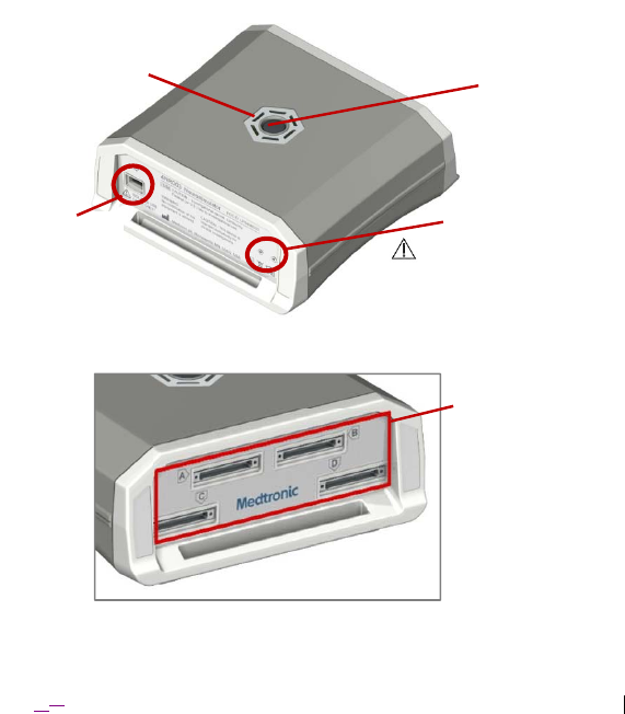
Figure 1. Model 4NR003 ENS (rear bezel with USB connection interface shown).
Figure 2. Model 4NR003 ENS (front bezel with lead connection interfaces shown).
Pin Resets
(DO NOT USE –
Medtronic Use ONLY)
USB Port
Power Button
Lead Connection
Interfaces
Light-Emitting
Diodes (LEDs)

English10 2016‐0810‐01
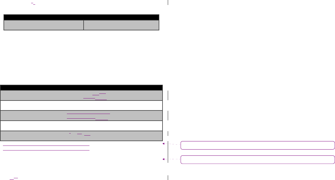
Table 1. Physical characteristics of the Model 4NR003 ENSa
Description Value
Length 5.01 in (127.25 mm)
Width 4.94 in (125.48 mm)
Thickness 2.11 in (53.59 mm)
Weight (without batteries) 509.0 g (18.0 oz)
Universal Serial Bus port USB Mini-B
Lead Interface Connector jack Omnetics A29100-065 (x 4)b
Wireless Communication
Interface
2.4 GHz WiFibc
a All measurements are approximate.
b The connector interfaces support connection to lead adapters designed for clinical leads commonly
used in Epilepsy Monitoring Units.
c Connection interface is limited to a single point-to-point connection with an authenticated device, and
communications are encrypted.
Table 2. Electrical specifications for the Model 4NR003 ENS
Description Value
Nominal Operating Voltage 4.5V DC
Maximum Voltage 5V DC
Nominal Operating Current 250 mA
Maximum Current 1.5 A (continuously fused)
Nominal Operating Power 1.125 W
2016‐1008‐01 English11
Table 3. ENS electrical and operating characteristics
Description Value
Power Source AA Lithium batteries (quantity 3)
Battery Life 20 hours minimuma
Operating Type Continuous
Degree of protection
against electrical
shock
Type BF
Ingress protection IPX0 – normal equipment
Case material (1) Polycarbonate/ABS blend plastic resin
(2) Cycoloy C2950 – Polycarbonate/acrylonitrile
butadiene styrene (PC/ABS)
(
3
)
Santoprene 211-45 thermoplastic vulcanizate
Automatic shut off Configurable inactivity timer that upon expiration
powers down the device
Automatic
stimulation
terminationb
USB cable disconnected
Loss of WiFi connection to controlling computer
Battery level Surface LEDs (Figure 1) indicate battery level:
Green – Normal
Orange – Less than 20% battery life remaining
Red – Batteries depleted, replacement needed
Connection Status Surface LEDs (Figure 1) indicate connection status:
Flashing Colorc – Disconnected/Connecting
Solid Color – Connected
Stimulation Status Surface LEDs (Figure 1) indicate stimulation state:
Blue – Stimulation being delivered
Other Color – No stimulation
a Battery life is based on continuous stimulation driven over a WiFi connection by computational
algorithms running on a controlling computer to eight pairs of electrodes with a 1000 Ω load
impedance with the following energy characteristics: Amp = 4mA, PW = 300 µs, Rate = 400 Hz,
while sensing on four differential channels at 1000 Hz.
b The ENS will terminate the administration of stimulation upon the detection of a dropped
connection with the controlling computer (defined as 1000ms of lost communications).
c Displayed color is specific to the battery level of the ENS at the given time. For example, when
connecting to an ENS that has sufficient battery power, the LEDs will flash in green.
Comment [BZ1]: IhadthoughtthiswouldneedtochangebutIdon’tthink
sonowthatIreadthis–areyoucomfortable?
English12 2016‐0810‐01
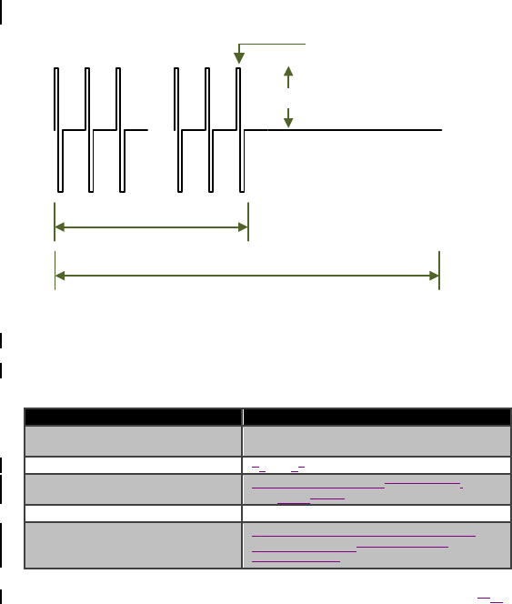
...
FPULSE (Hz)
Amplitude
PulseWidth(µs)
#Pulses
PulseTrainCycleDuration
Figure 3. Illustration of configurable characteristics of a stimulation pattern’s
pulse train
Table 4. Operating parameters for a stimulation pattern’s pulse train for the
Model 4NR003 ENS
Operating Parameter Operating Range and Resolutiona
Amplitudeb 4-256µA, with 4µA resolution
0.25-8.00mA, with 50µA resolution
Pulse Width 130-12270μs, with 10μs resolution
Pulse Frequency (FPULSE) 153mHz-1,000,000mHz0.15-5000Hz,,
with 1mHz100μs resolution
Number of Pulses 1-511 pulses, with 1 pulse resolution
Pulse Train Cycle Duration Maximum of 10 seconds, programmable
to 1mHz resolution50-1000ms, with
50ms resolution
2016‐1008‐01 English13
a Interlocks and excessive impedance between electrodes will prevent the use or delivery of
some parameter combinations.
b Step increments/decrements of amplitude are monotonic, and amplitudes delivered at a
tolerance of +/- 120.0%.
Table 5. Other operating stimulation parameters for the Model 4NR003 ENS
Operating Parameter Rangea
Global Amplitude Limit
(per stimulation channel) 4uA – Maximumb
a Interlocks and excessive impedance between electrodes will prevent the use or delivery of some
parameter combinations.
b Maximum will be set to the Shannon McCreery safe charge density limit (k=1.5) using the
surface area of the stimulation channel.
Table 6. Operating sense acquisition parameters for the Model 4NR003 ENS
Programmable Parameter Range and Defaults
Low Pass Filter 1 50Hz, 100Hz, 450800Hz
(Default: 800Hz450Hz)
Low Pass Filter 2 100Hz, 350Hz, 1700Hz
(Default: 1700Hz)
High Pass Filter 0.05Hz, 0.5Hz, or 2.5Hz
(Default: 0.5Hz)0.85Hz
Sampling Rate 250Hz, 500Hz, 1000Hz
(Default: 1000Hz)
Samples per Packet 1a, 2, or 4, 8b
(Default: 2)
a Only permitted when operating over a USB connection
b Only supported when 128 channels or less are defined
Formatted: Indent: Left: 0.06"
Formatted: Left

English14 2016‐0810‐01

2016‐1008‐01 English15

English16 2016‐0810‐01
Interactions with other medical equipment
In the clinical environment for which the ENS is intended for use, there are other
equipment, including medical equipment, whose functional performance can be
affected by the presence and use of this device.
The ENS will produce a stimulation pulse on specified electrodes. This signal will
disrupt neurological recordings for the duration of the stimulation period. Once
stimulation ceases, neurological recordings return to baseline behavior.
Connections of the ENS to the controlling computer, including USB 2.0 and WiFi,
will produce emissions that could have an adverse effect on the performance of
other nearby equipment.
Caution: The device is not certified for use in the presence of a
flammable anesthetic mixture with air or with oxygen or nitrous oxide.
The consequences of using the device near flammable atmospheres are
unknown.
Caution: Do not use the device in the proximity of equipment that
generates electromagnetic interference (EMI). Sources of EMI may result
in (a) operational changes to the neurostimulator, causing it to turn on or
off, or to reset to power-on-reset (POR) settings, and (b) a momentary
increase in stimulation or intermittent stimulation, effects that may be
observable by the patient.
Caution: This device should not be used in proximity to magnetic
resonance imaging (MRI) equipment. The consequences of exposing the
device to MRI equipment are unknown.

2016‐1008‐01 English17
Description of leads tested for compatibility
The Model 4NR003 ENS has been tested and is compatible with the following leads
and extensions:
Ad-Tech Medical
o SD08R-SP10X-000: 8-contact depth; 10mm spacing (lead)
o L-SRL-8DIN: 8-contact, Cambrio extension cable
o IG64C-SP10X-0TB: 64-contact, single-tail LTM grid (lead)
o L-SRL-64BDIN: 64-contact, Cambrio extension cable

English18 2016‐0810‐01
Electromagnetic compatibility declaration
Tables 7, 8, 9, and 10 apply to the Model 4NR003 ENS.
Table 7. Guidance and manufacturer’s declaration – electromagnetic emissions
The Model 4NR003 ENS is intended for use in the electromagnetic
environment specified below. The customer or the user of the Model
4NR003 ENS should ensure that it is used in such an environment.
Emissions Test Compliance Electromagnetic environment –
guidance
Radio-frequency
(RF) emissions
CISPR 11(EN
50511)
Group 1 The model 4NR003 ENS uses RF
energy only for its internal
function. Therefore, its RF
emissions are very low and are not
likely to cause any interference in
nearby electronic equipment.
RF emissions
CISPR 11 (EN
50511)
Class A The Model 4NR003 ENS is
suitable for use in all
establishments, including domestic
establishments and those directly
connected to the public low-
voltage power supply network that
supplies buildings used for
domestic purposes.
Harmonic
Emissions
EN 61000-3-2
Not
applicable
for a battery-
powered
device
The Model 4NR003 ENS is
suitable for use in all
establishments, including domestic
establishments and those directly
connected to the public low-
voltage power supply network that
supplies buildings used for
domestic purposes.
Voltage
fluctuations/flicker
emissions
EN61000-3-3
Not
applicable
for a battery-
powered
device

2016‐1008‐01 English19
Table 8. Guidance and manufacturer’s declaration – electromagnetic immunity
The Model 4NR003 ENS is intended for use in the electromagnetic
environment specified below. The customer or the user of the Model 4NR003
ENS should ensure that it is used in such an environment.
Immunity Test EN 60601 test
level
Compliance
level
Electromagnetic
environment –
guidance
Electrostatic
discharge (ESD):
EN 61000-4-2
±6kV contact
±8kV air
±2kV, ±4kV,
±6kV contact
±2kV, ±4kV,
±8kV air
Floors should be
wood, concrete, or
ceramic tile. If
floors are covered
with synthetic
material, the
relative humidity
should be at least
30%.
Electrical fast
transient/burst:
EN 61000-4-4
±2kV for
power supply
lines
±1kV for
input/output
lines
±2kV for
power supply
lines
±1kV for
input/output
lines
Mains power quality
should be that of a
typical commercial
or hospital
environment.
Surge:
EN 61000-4-5
±1kV line(s) to
line(s)
±2kV line(s) to
earth
±1kV
differential
mode
±2kV common
mode
Mains power quality
should be that of a
typical commercial
or hospital
environment.
English20 2016‐0810‐01
Immunity Test EN 60601 test
level
Compliance
level
Electromagnetic
environment –
guidance
Voltage dips,
short
interruptions and
voltage
variations on
power supply
input lines:
EN 61000-4-11
<5% UT
(>95% dip in
UT ) for 0,5
cycle
40% UT (60%
dip in UT ) for
5 cycles
70% UT (30%
dip in UT ) for
25 cycles
<5% UT
(>95% dip in
U
T
) for 5 s
<5% UT
(>95% dip in
UT ) for 0,5
cycle
40% UT (60%
dip in UT ) for 5
cycles
70% UT (30%
dip in UT ) for
25 cycles
<5% UT
(>95% dip in
U
T
) for 5 s
Mains power quality
should be that of a
typical commercial
or hospital
environment.
Power frequency
(50/60 Hz)
magnetic field
EN 61000-4-8
30 A/m 30 A/m Mains power quality
should be that of a
typical commercial
or hospital
environment.
NOTE UT is the a.c. mains voltage prior to application of the test level.

2016‐1008‐01 English21

English22 2016‐0810‐01
Table 9. Guidance and manufacturer’s declaration – electromagnetic immunity
The Model 4NR003 ENS is intended for use in the electromagnetic environment specified
below. The customer or the user of the Model 4NR003 ENS should ensure that it is used
in such an environment.
Immunity
Test
EN 60601
test level
Compliance
level
Electromagnetic environment –
guidance
Conducted RF
EN 61000-4-6
Radiated RF
EN 61000-4-3
3 Vrms
150 kHz to 80
MHz
3 V/m
80 MHz to 2,5
GHz
3 Vrms
3 V/m
Portable and mobile RF communications
equipment should be used no closer to
any part of the Model 4NR003 ENS,
including cables, than the recommended
separation distance calculated from the
equation applicable to the frequency of
the transmitter.
Recommended separation distance
d = 1,2 P
d = 1,2 P 80 MHz to 800 MHz
d = 2,3 P 800 MHz to 2,5 GHz
where P is the maximum output power
rating of the transmitter in watts (W)
according to the transmitter manufacturer
and d is the recommended separation
distance in metres (m).
Field strengths from fixed RF
transmitters, as determined by an
electromagnetic site surveya, should be
less than the compliance level in each
frequency range.b
2016‐1008‐01 English23
Immunity
Test
EN 60601
test level
Compliance
level
Electromagnetic environment –
guidance
NOTE 1 At 80 MHz and 800 MHz, the higher frequency range applies.
NOTE 2 These guidelines may not apply in all situations. Electromagnetic propagation is affected
by absorption and reflection from structures, objects and people.
a Field strengthsfrom fixed transmitters, such as base stations for radio (cellular/cordless)
telephones and land mobile radios, amateur radio, AM and FM radio broadcast and TV broadcast
cannot be predicted theoretically with accuracy. To assess the electromagnetic environment due to
fixed RF transmitters, an electromagnetic site survey should be considered. If the measured field
strength in the location in which the Model 4NR003 ENS is used exceeds the applicable RF
compliance level above, the Model 4NR003 ENS should be observed to verify normal operation. If
abnormal performance is observed, additional measures may be necessary, such as re-orienting or
relocating the Model 4RNR003 ENS.
b Over the frequency range 150 kHz to 80 MHz, field strengths should be less than 3 V/m.
English24 2016‐0810‐01
Table 10. Recommended separation distances between portable and mobile RF
communications equipment and the Model 4NR003 ENS
The Model 4NR003 ENS is intended for use in an electromagnetic
environment in which radiated RF disturbances are controlled. The customer
or the user of the Model 4NR003 ENS can help prevent electromagnetic
interference by maintaining a minimum distance between portable and
mobile RF communications equipment (transmitters) and the Model 4NR003
ENS as recommended below, according to the maximum output power of the
communications equipment.
Rated
maximum
output
power of
transmitter
W
Separation distance according to transmitter Power Output
(meters)
150 kHz to 80 MHz
outside ISM bands
d = 3.5 P
150 kHz to 80 MHz
in ISM bands
d = 1.2 P
80 MHz to
800 MHz
d = 1.2 P
800 MHz to
2,5 GHz
D = 2.3 P
0,01 0,35 1,2 0,12 0,23
0,1 1,1 3,8 0,38 0,73
1 3,5 12 1,2 2,3
10 11 38 3,8 7,3
100 35 120 12 23
For transmitters rated at a maximum output power not listed above, the recommended
separation distance d in meters (m) can be determined using the equation applicable to
the frequency of the transmitter, where P is the maximum output power rating of the
transmitter in watts (W) according to the transmitter manufacturer.
NOTE 1 At 80 MHz and 800 MHz, the separation distance for the higher frequency
range applies.
NOTE 2 The ISM (industrial, scientific and medical) bands between 150 kHz and 80
MHz are 6,765 MHz to 6,795 MHz; 13,553 MHz to 13,567 MHz; 26,957 MHz to 27,283
MHz; and 40,66 MHz to 40,70 MHz.
NOTE 3 The recommended separation distances between portable and mobile radio-
frequency (RF) communications equipment are not applicable to the equipment
provided by Medtronic that have been identified as a programming component used in
conjunction with the Model 4RNR003 ENS.

2016‐1008‐01 English25

English26 2016‐0810‐01
Means of operator and patient protection
The ENS is designed with means of protection to ensure the safety of both the
patient and operator during use (per EN 60601-1), including when it is connected to
a controlling computer via USB 2.0 or WiFi.
The ENS is internally powered portable medical electrical (ME) equipment when it is
not USB-connected to a controlling computer. The USB connection from the
controlling computer powers the device’s USB port, so the device is considered
Class I medical electrical equipment in this configuration.
Table 11. Means of operator and patient protections provided by Model 4NR003
ENS
ME
Equipment
Classification
Operator
Protection(s)
Patient Protection(s)
Internally
Powered
Not applicable – no
connection to supply
mains
(1) Reverse battery
protection on battery
terminals
(2) AC-coupling of output
signals to patient,
preventing DC current to
patient
Class I
ENS specified for
use only with USB
cables up to 3
meters in length that
support electrical
isolation from
voltages up to 240 V
(e.g. IFTOOLS
ISOUSB-Cable-M).
(1) ESD protection (TVS
diodes) on the USB
circuitry provides
protection up to15 kV
(contact) and 30kV (air).
(2) AC-coupling of output
signals to patient,
preventing DC current
2016‐1008‐01 English27
Instructions for use
The ENS is used to collect neurological signals and deliver stimulation energy upon
request in support of clinical research in an acute, clinical environment.
Caution: Do not modify this equipment. Modification of this
equipment can result in damage to the device, causing the device to
malfunction or become unusable.
Caution: Use of this equipment adjacent to or stacked with other
equipment should be avoided because it could result in improper
operation. If such use is necessary, this equipment and the other
equipment should be observed to verify that they are operating
normally.
Caution: Use of transducers or cables, other than those specified in
this document, is not recommended as use of these components may
result in increased emissions or decreased immunity of the ENS.
Caution: To avoid the risk of electric shock, ensure that any
equipment connected directly to the ENS is only connected to supply
mains with protective earth.
Caution: Secure the device at all times so as to prevent blunt impacts
to the device (e.g. from accidental drops). Blunt impact trauma to the
device may result in device malfunction, including unexpected
stimulation performance.
Caution: Do not touch the pins on the ENS’s lead connection
interfaces, especially while also in contact with the patient. Static
charges can discharge to the patient, resulting in potential harm.
English28 2016‐0810‐01
Caution: Do not touch the pins on the ENS’s lead connection
interfaces or put the pins in contact with metal objects. In addition,
use care when transporting the ENS in static-prone areas (e.g.
carpeted floors). If the ENS is connected to implanted patient leads,
static charge discharged to the pins may pass through the leads and
cause dama
g
e to patient tissue.
Caution: Use the ENS only with equipment that is delivered with the
device or is otherwise specified as compatible.
Caution: Consult with assigned IT support personnel prior to
configuring a communication session using WiFi. Wireless
performance will vary based on the environment. It is recommended
that the ENS be setup for WiFi communications on a channel
identified by IT support personnel as having the most available
bandwidth and as being least likely to interfere with other ENS or
medical devices being used in the area.
Note: Before placing the ENS into operation, ensure the ENS has had time to adjust to
the current temperature and environment.

2016‐1008‐01 English29
Using the ENS during a research study
Ensure the ENS is powered on and then connect to it from the controlling computer.
Follow the instructions on setting up communications with the controlling computer
that are contained in the applicable research study protocol.
Inserting batteries into the ENS
See section “Replacing the ENS batteriesReplacing the ENS batteries” for
instructions.
English30 2016‐0810‐01
Connecting the USB connector cable to the ENS
When used during a research study, the ENS is connected to a controlling computer
equipped with the Odin Interface Software either via a USB connection or WiFi
connection. The USB connector cable can be connected to the ENS to enable a
USB connection to the controlling computer. Follow the instructions on setting up
communications with the controlling computer that are contained in the applicable
research study protocol.
Caution: Use only USB cables up to 3 meters in length that support
electrical isolation from voltages up to 240 V (e.g. IFTOOLS
ISOUSB-Cable-M). Use of unsupported cables can cause damage
to electronic components of the device and may cause an electrical
shock to the patient if connected.
Caution: USB is designed as a secondary communication
mechanism to WiFi and should only be used when WiFi
performance is inadequate for the needs of the experiment.
Caution: Disconnect the controlling computer from wall power while
USB-connected to the ENS. Failure to disconnect may cause a
transfer of energy to the patient in the event of a power surge to the
wall outlet.
Matching the keyed slots of the USB Mini-B connector plug and the USB Mini-B
connector jack, push the plug end of
the connector cable fully into the USB
Mini-B connector jack on the ENS. Failure to fully seat the USB connector plug
may result in intermittent connectivity
Note: Attempting to connect the USB connector cable while the ENS is currently
connected to the controlling computer via WiFi will result in the automatic re-
establishment of the connection using USB. If sensing was enabled at the time of this
action, neurological sense data will no longer be collected until the reconnection
sequence is complete.
... [1]
2016‐1008‐01 English31
Connecting the lead interface adapter cables to the ENS
Caution: Do not pull on the cable. Pulling on the cable may break a
wire or dislodge the lead. A broken wire or dislodged lead may result
in loss of stimulation and may require surgery to replace the lead.
Caution: Do not use the ENS with unsupported clinical EEG
equipment. The ENS is capable of operating with EEG monitoring
hardware that supports an input voltage of up to 17 V without damage
or clipping, a minimum input impedance of 50 kΩ, and isolation from
voltages up to 240 V.
Caution: Use only the Blackrock Microsystems Adapter PN9770
#A0263 revision 2.00 with the ENS. Other lead interface adapter
cables have not been tested with this device, and use of these cables
may result in unexpected device performance.
Matching the keyed slots of the connector plug and the Omnetics connector
jack, slowly guide the plug end of
the adapter cable fully into the jack, using a
side-to-side motion. The adapter plug has bi-lobe keys that ensure the plug is
oriented correctly, so undue force to fully seat the plug is not necessary. After
plugging in the adapter plug, perform a visual inspection to ensure the plug is
fully seated (i.e. no gaps on the metal shrouds between the mating connectors).
Notes:
▪ If the Omnetics connector jack will not easily receive the adapter plug, perform a
visual magnified examination of the plug and connector jack to ensure there are no
bent pins and that pin alignment is consistent in each row.
▪ The ENS contains four Omnetics connector jacks labeled A-D. To avoid confusion
when configuring sense and stimulation on electrodes during an experiment, make
particular note of the interfacing electrodes that are connected to each Omnetics
connector jack.
English32 2016‐0810‐01
Configuring the ENS for sensing and stimulation
Caution: Evaluate the safety of stimulation to intended lead contacts
prior to commencing with the research study. This can be
accomplished by incrementing stimulation energy to each intended
channel to observe patient side effects until side effects are observed
or the intended stimulation amplitude tar
g
et is reached.
Caution: Avoid excessive stimulation. There is a potential risk of brain
tissue damage from high amplitude and wide pulse width parameter
settings.
The ODIN Configuration Tool Instructions for Use, shipped separately with the Odin
Research System Interface Software, provides instructions for developing a sense
and stimulation channel configuration file that can be used to configure the device
for sensing and stimulation during a research study. Consult this documentation and
the associated research study protocol for details on configuring and running an
experiment using the ENS.
To power on the ENS:
Press and hold the power button on the upper surface of the ENS (Figure 1)
until LEDs surrounding the button begin to rotate in white color (i.e. about two
seconds) to indicate the device is initializing.
2016‐1008‐01 English33
Notes:
For sensing applications using a common reference, connect all “Ref” lines
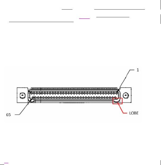
from each Omnetics connection jack (A-D) (Figure 4) that is in use and
connect the combined signal to the reference input on the jackbox. All
Omnetics connection jacks used must have the Ref lines connected for
sensing to function as designed.
Identify the Emergency Stop “Esc” key location on the controlling computer
prior to starting an experiment. In the event that stimulation needs to be
terminated during the experiment, this “Esc” key, referenced in the
associated research study protocol, will terminate stimulation delivery when
pressed.
Once connected to a controlling computer over USB, the ENS will refuse
connection requests using WiFi. To enable the ENS to connect using WiFi
once a USB session has been established, power-cycle the ENS. Take note
of stored configurations, as power-cycling the ENS will reset its configuration.
Figure 4. Omnetics A29100-065 connector jack as viewed with the ENS top side
up. Pin 65 (labeled) is the Ref line.

English34 2016‐0810‐01
2016‐1008‐01 English35
Terminating stimulation delivery
The delivery of stimulation, including stimulation programmed for delivery in the
future, can be terminated upon request. One method is by pressing the Emergency
Stop key. The Emergency Stop key is located on the controlling computer as the
“Esc” key. Take note of this key’se Emergency Stop key location, referenced in the
associated research study protocol, prior to starting an experiment.
To terminate the administration of stimulation:
Press the Emergency Stop key on the controlling computer. Consult the
research study protocol for detailed instructions.
OR
Press the power button on the upper surface of the ENS (Figure 1).
Caution: Take note of stored configuration settings before turning
off power to the ENS. Interruption of power to the ENS will cause
stored configurations, including those for sensing and stimulation, to
reset.
Formatted: Font: Not Bold
Formatted: Not Raised by / Lowered by
English36 2016‐0810‐01
Disconnecting lead interface adapter cables from the ENS
Caution: Take note of stored configuration settings before turning
off power to the ENS. Interruption of power to the ENS will cause
stored configurations, including those for sensing and stimulation, to
reset.
1. Press the power button on the upper surface of the ENS to turn it off (Figure 1).
2. Disconnect each lead interface adapter cable from the ENS, one at a time.
Slowly remove the connector plug using a side-to-side pulling motion until it is
released from the jack.
F
... [2]
2016‐1008‐01 English37
Replacing the ENS batteries
Replace the ENS batteries before each use and when the batteries are low or
depleted. The battery status is displayed by LEDs (Figure 1) that surround the power
button on the ENS’s top surface.
Cautions:
▪ If batteries are replaced during a research study, stored sense
and stimulation configuration may not reflect recent
configurations.
▪ Replace batteries using the correct polarity. Reversing polarity
when installing new batteries may result in unexpected device
function and/or performance.
▪ Do not mix chemistries or brands when replacing batteries.
Only use Energizer Ultimate Lithium AA batteries when
replacing the ENS batteries. Other battery types, such as
Alkaline or rechargeable, or batteries from other manufacturers,
are not supported and may cause damage to the electronic
components of the device.
▪ Take note of stored configuration settings before turning off
power to the ENS. Interruption of power to the ENS will cause
stored configurations, including those for sensing and
stimulation, to reset.
1. End the experiment and disconnect the ENS from the controlling computer, if
applicable. Consult the applicable research study protocol for instructions on
ending the experiment appropriately.
2. Turn off the ENS by pressing the power button, if applicable.
3. Press into each of the battery compartment tabs to release the battery
compartment cover (Figure 5). Pull the cover to remove.
4. Insert three new Energizer Ultimate Lithium AA batteries. Correct battery polarity is
indicated inside the battery compartment.
5. Replace the battery compartment cover.
Notes:
▪ Dispose of depleted batteries according to local requirements.
English38 2016‐0810‐01
Figure 5. Model 4NR003 ENS (underside surface shown).
Battery
com
p
artment tabs

2016‐1008‐01 English39
Troubleshooting
Intermittent WiFi connections
The nature of the environment may produce interference that results in intermittent
or no WiFi connection from the ENS to the controlling computer. The following
suggestions are recommended to remedy intermittent WiFi connections:
Reduce or eliminate interfering sources, if possible. For example, phones or
other personal items may be removed from the room, or supply mains to the
controlling computer may be disconnected.
Check the WiFi connection on the controlling computer. See the applicable
research study protocol for detailed instructions.
Move the ENS to a different area of the room where fewer interfering sources
are present.
Reconnect the ENS using a USB connection. Consult the research study
protocol for instructions on configuring this connection.

English40 2016‐0810‐01

2016‐1008‐01 English41
Device care and storage
▪ Check the battery status of the ENS before each research study.
▪ Replace low or depleted batteries.
▪ Handle the device and system components with care. Do not drop, strike or
step on the device or system components.
▪ Do not dismantle or tamper with the device.
▪ Store the ENS at room temperature. Avoid extreme hot or cold temperatures
and direct sunlight.
▪ Upon completion of the research study (or if device is no longer operating as
expected), contact the clinical study site coordinator to return the device. Do not
dispose of devices.
English42 2016‐0810‐01
Cleaning the ENS
Cautions:
▪ Avoid application of any chemicals to the batteries underneath
the battery compartment door. The application of moisture to
the batteries may cause damage to electronic components.
▪ The device and system components are not waterproof. Do
not allow moisture to get inside the device or system
components.
▪ Before cleaning the device, be aware that the cleaning
procedures identified in this document do not protect against
contamination by blood-borne pathogens or other potentially
infectious materials.
1. Use a damp cloth with a 1:10 dilution of sodium hypochlorite or a 70%
isopropyl alcohol wipe to clean the exterior of the ENS.
2. Wipe the ENS with a clean cloth dampened with clean water.
3. Dry with a clean cloth.
Notes:
To wipe the recess areas around the battery compartment door, it may
be necessary to remove the battery compartment door.
The battery contacts may be cleaned periodically with a cotton swab
dampened with a solution containing up to 70% isopropyl alcohol. Do not
use a pencil eraser or sandpaper.

2016‐1008‐01 English43
Safety and technical checks
Periodic safety and technical checks or periodic maintenance of the ENS are not
required.
The ENS contains no serviceable components. If the ENS is nonfunctional or
otherwise requires repair or replacement, contact the clinical study site coordinator for
instructions to return the unit.
Manufacturer
Medtronic, Inc.
7000 Central Ave
Minneapolis, MN 55432
USA
www.medtronic.com
Tel. 1-763-505-5000
Fax 1-763-505-1000
Authorized Representative
in the European Community
Medtronic B.V.
Earl Bakkenstraat 10,
6422 PJ Heerlen,
The Netherlands
Tel. +31-45-566-8000
Fax +31-45-566-8668
Europe/Africa/Middle East
Headquarters
Medtronic International Trading Sàrl
Route du Molliau 31,
Case Postale 84
CH-1131 Tolochenaz,
Switzerland
www.medtronic.eu
Tel. +41-21-802-7000
Fax +41-21-802-7900
© Medtronic, Inc. 2016 All Rights Reserved
M966503A001 Rev BC

Page 30: [1] Comment [BZ2] Zingsheim, Brandon 9/6/2016 4:56:00 PM
Daleisthisstilltrueoristheusergoingtoberequiredtore‐enablesensing?
Page 36: [2] Formatted Zingsheim, Brandon 9/6/2016 5:05:00 PM
NotRaisedby/Loweredby