Medtronic OS1E100 Vital Syn Wearable Sp02 Patient Monitoring System User Manual PT00015629
Medtronic, Inc. Vital Syn Wearable Sp02 Patient Monitoring System PT00015629
User Manual

Operator's Manual
Vital Sync
Wearable SpO2 Patient Monitoring System
TM
Exhibit #8
Medtronic, the Medtronic logo, and Further, Together are trademarks of Medtronic. Other brands are
trademarks of a Medtronic company.
This manual © 2015, 2016 Medtronic. All rights reserved.

Operator’s Manual iii
Table of Contents
1 Introduction
1.1 Overview . . . . . . . . . . . . . . . . . . . . . . . . . . . . . . . . . . . . . . . . . . . . . . . . . 1-1
1.2 Intended Audience . . . . . . . . . . . . . . . . . . . . . . . . . . . . . . . . . . . . . . . . 1-1
1.3 Safety Information . . . . . . . . . . . . . . . . . . . . . . . . . . . . . . . . . . . . . . . . 1-2
1.3.1 Safety Symbols . . . . . . . . . . . . . . . . . . . . . . . . . . . . . . . . . . . . . . . . . . . . . . . . . . . 1-2
1.3.2 Warnings . . . . . . . . . . . . . . . . . . . . . . . . . . . . . . . . . . . . . . . . . . . . . . . . . . . . . . . . . 1-2
1.3.3 Cautions . . . . . . . . . . . . . . . . . . . . . . . . . . . . . . . . . . . . . . . . . . . . . . . . . . . . . . . . . 1-5
1.3.4 Notes . . . . . . . . . . . . . . . . . . . . . . . . . . . . . . . . . . . . . . . . . . . . . . . . . . . . . . . . . . . . 1-5
1.4 Obtaining Technical Assistance . . . . . . . . . . . . . . . . . . . . . . . . . . . . 1-6
1.4.1 Technical Services . . . . . . . . . . . . . . . . . . . . . . . . . . . . . . . . . . . . . . . . . . . . . . . . 1-6
1.4.2 Related Documents . . . . . . . . . . . . . . . . . . . . . . . . . . . . . . . . . . . . . . . . . . . . . . 1-7
1.5 Revision History . . . . . . . . . . . . . . . . . . . . . . . . . . . . . . . . . . . . . . . . . . . 1-7
1.6 Warranty Information . . . . . . . . . . . . . . . . . . . . . . . . . . . . . . . . . . . . . 1-7
1.7 Licensing Information . . . . . . . . . . . . . . . . . . . . . . . . . . . . . . . . . . . . . 1-8
1.8 HIPAA Disclaimer . . . . . . . . . . . . . . . . . . . . . . . . . . . . . . . . . . . . . . . . . . 1-8
2 Product Overview
2.1 Overview . . . . . . . . . . . . . . . . . . . . . . . . . . . . . . . . . . . . . . . . . . . . . . . . . 2-1
2.2 Product Description . . . . . . . . . . . . . . . . . . . . . . . . . . . . . . . . . . . . . . . 2-1
2.3 Indications for Use . . . . . . . . . . . . . . . . . . . . . . . . . . . . . . . . . . . . . . . . 2-2
2.4 Components and Accessories . . . . . . . . . . . . . . . . . . . . . . . . . . . . . . 2-2
2.5 Views . . . . . . . . . . . . . . . . . . . . . . . . . . . . . . . . . . . . . . . . . . . . . . . . . . . . . 2-3
2.5.1 Module . . . . . . . . . . . . . . . . . . . . . . . . . . . . . . . . . . . . . . . . . . . . . . . . . . . . . . . . . . 2-3
2.5.2 Module with Connected Sensor . . . . . . . . . . . . . . . . . . . . . . . . . . . . . . . . . . 2-3
2.5.3 Docking Station . . . . . . . . . . . . . . . . . . . . . . . . . . . . . . . . . . . . . . . . . . . . . . . . . . 2-4
2.6 Symbols and Descriptions . . . . . . . . . . . . . . . . . . . . . . . . . . . . . . . . . 2-4
2.6.1 Monitoring System Module . . . . . . . . . . . . . . . . . . . . . . . . . . . . . . . . . . . . . . . 2-4
2.6.2 Packaging and Labeling . . . . . . . . . . . . . . . . . . . . . . . . . . . . . . . . . . . . . . . . . . 2-5
3 Docking Station Setup and Operation
3.1 Overview . . . . . . . . . . . . . . . . . . . . . . . . . . . . . . . . . . . . . . . . . . . . . . . . . 3-1
3.2 Safety Reminders . . . . . . . . . . . . . . . . . . . . . . . . . . . . . . . . . . . . . . . . . 3-1
3.3 Setup . . . . . . . . . . . . . . . . . . . . . . . . . . . . . . . . . . . . . . . . . . . . . . . . . . . . . 3-1
3.4 Operation . . . . . . . . . . . . . . . . . . . . . . . . . . . . . . . . . . . . . . . . . . . . . . . . . 3-2
3.4.1 Power On and Power Off . . . . . . . . . . . . . . . . . . . . . . . . . . . . . . . . . . . . . . . . . 3-2
3.4.2 Module Battery Recharge . . . . . . . . . . . . . . . . . . . . . . . . . . . . . . . . . . . . . . . . . 3-2
3.5 Cleaning and Disinfection . . . . . . . . . . . . . . . . . . . . . . . . . . . . . . . . . 3-3
3.6 Troubleshooting . . . . . . . . . . . . . . . . . . . . . . . . . . . . . . . . . . . . . . . . . . 3-3

iv Operator’s Manual
4 Module and Sensor Setup and Operation
4.1 Overview . . . . . . . . . . . . . . . . . . . . . . . . . . . . . . . . . . . . . . . . . . . . . . . . . 4-1
4.2 Safety Reminders . . . . . . . . . . . . . . . . . . . . . . . . . . . . . . . . . . . . . . . . . 4-1
4.3 Setup . . . . . . . . . . . . . . . . . . . . . . . . . . . . . . . . . . . . . . . . . . . . . . . . . . . . . 4-2
4.4 Operation . . . . . . . . . . . . . . . . . . . . . . . . . . . . . . . . . . . . . . . . . . . . . . . . . 4-2
4.4.1 Power On and Power Off . . . . . . . . . . . . . . . . . . . . . . . . . . . . . . . . . . . . . . . . . 4-2
4.4.2 Monitor a Patient . . . . . . . . . . . . . . . . . . . . . . . . . . . . . . . . . . . . . . . . . . . . . . . . . 4-3
4.4.3 Change Alarm Thresholds . . . . . . . . . . . . . . . . . . . . . . . . . . . . . . . . . . . . . . . . 4-5
4.4.4 Battery Recharge . . . . . . . . . . . . . . . . . . . . . . . . . . . . . . . . . . . . . . . . . . . . . . . . . 4-6
4.5 Alarm Thresholds . . . . . . . . . . . . . . . . . . . . . . . . . . . . . . . . . . . . . . . . . 4-6
4.6 Troubleshooting . . . . . . . . . . . . . . . . . . . . . . . . . . . . . . . . . . . . . . . . . . 4-7
5 Performance Considerations
5.1 Overview . . . . . . . . . . . . . . . . . . . . . . . . . . . . . . . . . . . . . . . . . . . . . . . . . 5-1
5.2 Oximetry Considerations . . . . . . . . . . . . . . . . . . . . . . . . . . . . . . . . . . 5-1
5.2.1 Monitoring System Constraints . . . . . . . . . . . . . . . . . . . . . . . . . . . . . . . . . . . 5-1
5.2.2 Sensor Performance Considerations . . . . . . . . . . . . . . . . . . . . . . . . . . . . . . 5-1
5.3 Patient Conditions . . . . . . . . . . . . . . . . . . . . . . . . . . . . . . . . . . . . . . . . 5-3
5.4 Reducing Electromagnetic Interference (EMI) . . . . . . . . . . . . . . . 5-4
6 Product Maintenance
6.1 Overview . . . . . . . . . . . . . . . . . . . . . . . . . . . . . . . . . . . . . . . . . . . . . . . . . 6-1
6.2 Cleaning and Disinfection . . . . . . . . . . . . . . . . . . . . . . . . . . . . . . . . . 6-1
6.2.1 Cleaning and Disinfecting Agents . . . . . . . . . . . . . . . . . . . . . . . . . . . . . . . . 6-1
6.2.2 Clean the Module . . . . . . . . . . . . . . . . . . . . . . . . . . . . . . . . . . . . . . . . . . . . . . . . 6-2
6.2.3 Disinfect the Module . . . . . . . . . . . . . . . . . . . . . . . . . . . . . . . . . . . . . . . . . . . . . 6-3
6.2.4 Clean or Disinfect the Docking Station . . . . . . . . . . . . . . . . . . . . . . . . . . . . 6-5
6.3 Module Battery Recharge . . . . . . . . . . . . . . . . . . . . . . . . . . . . . . . . . . 6-5
6.4 Service. . . . . . . . . . . . . . . . . . . . . . . . . . . . . . . . . . . . . . . . . . . . . . . . . . . . 6-6
7 Troubleshooting
7.1 Overview . . . . . . . . . . . . . . . . . . . . . . . . . . . . . . . . . . . . . . . . . . . . . . . . . 7-1
7.2 Monitoring System Troubleshooting . . . . . . . . . . . . . . . . . . . . . . . 7-1
7.3 Docking Station Troubleshooting . . . . . . . . . . . . . . . . . . . . . . . . . . 7-3

Operator’s Manual v
Table of Contents
8 Product Specifications
8.1 Physical Characteristics . . . . . . . . . . . . . . . . . . . . . . . . . . . . . . . . . . . . 8-1
8.2 Battery . . . . . . . . . . . . . . . . . . . . . . . . . . . . . . . . . . . . . . . . . . . . . . . . . . . 8-1
8.3 Environmental Conditions . . . . . . . . . . . . . . . . . . . . . . . . . . . . . . . . . 8-2
8.3.1 Operating . . . . . . . . . . . . . . . . . . . . . . . . . . . . . . . . . . . . . . . . . . . . . . . . . . . . . . . . 8-2
8.3.2 Transport and Storage . . . . . . . . . . . . . . . . . . . . . . . . . . . . . . . . . . . . . . . . . . . . 8-2
8.4 Product Compliance . . . . . . . . . . . . . . . . . . . . . . . . . . . . . . . . . . . . . . . 8-3
8.5 Manufacturer’s Declaration and Guidance . . . . . . . . . . . . . . . . . . 8-3
8.5.1 Electromagnetic Compatibility (EMC) . . . . . . . . . . . . . . . . . . . . . . . . . . . . . 8-3
8.5.2 FCC Compliance . . . . . . . . . . . . . . . . . . . . . . . . . . . . . . . . . . . . . . . . . . . . . . . . . 8-7
8.6 Sensor Accuracy and Ranges . . . . . . . . . . . . . . . . . . . . . . . . . . . . . . . 8-8
8.7 Essential Performance . . . . . . . . . . . . . . . . . . . . . . . . . . . . . . . . . . . . . 8-9
A Clinical Studies
A.1 Overview . . . . . . . . . . . . . . . . . . . . . . . . . . . . . . . . . . . . . . . . . . . . . . . . .A-1
A.2 Methods . . . . . . . . . . . . . . . . . . . . . . . . . . . . . . . . . . . . . . . . . . . . . . . . . .A-1
A.3 Study Population . . . . . . . . . . . . . . . . . . . . . . . . . . . . . . . . . . . . . . . . . .A-1
A.4 Study Results . . . . . . . . . . . . . . . . . . . . . . . . . . . . . . . . . . . . . . . . . . . . .A-1
A.5 Adverse Events or Deviations . . . . . . . . . . . . . . . . . . . . . . . . . . . . . .A-1
A.6 Conclusion . . . . . . . . . . . . . . . . . . . . . . . . . . . . . . . . . . . . . . . . . . . . . . . .A-1

Page Left Intentionally Blank
vi

1-1
1 Introduction
1.1 Overview
This manual describes the features, setup, and operation of the patient components
of the Vital Sync™ Wearable SpO
2
Patient Monitoring System, along with the docking
station used with the device.
This manual applies to the following products:
1.2 Intended Audience
This manual provides information to health-care professionals acting as caregivers in
low-acuity hospital or hospital-type settings for operation and maintenance of the
monitoring system.
Consult facility requirements and protocols for any additional training or skill require-
ments beyond those identified here for operation and maintenance of the monitoring
system.
Before using the monitoring system or the docking station, thoroughly read this
manual, as well as the user documentation for the monitoring application used as part
of the monitoring system.
OS1E
OS1ACC
Introduction
1-2 Operator's Manual
1.3 Safety Information
This section contains important information regarding the safe and correct use of the
Vital Sync Wearable SpO
2
Patient Monitoring System.
Other important safety information appears in various locations in this manual.
1.3.1
Safety Symbols
1.3.2 Warnings
The following warnings apply when using the monitoring system.
||new warnings and draft warnings possibly to be added are in blue text||
Hazard Warnings
WARNING:
Electrical shock hazard — Do not soak the monitoring system module or submerge it into
any liquids.
WARNING:
Always disconnect and remove the monitoring system module and sensor during
magnetic resonance imaging (MRI) scanning. Attempting to use the monitoring system
during an MRI procedure could cause burns or adversely affect the MRI image or the
monitoring system's accuracy.
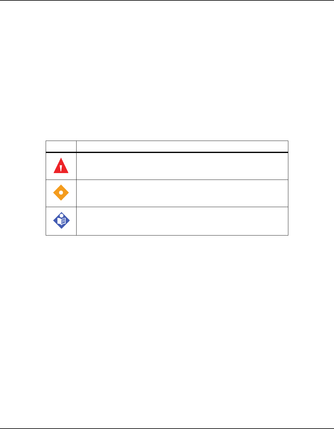
Table1-1.
Safety Symbol Definitions
Symbol Definition
WARNING
Warnings alert users to potential serious outcomes (death, injury, or adverse events) to the
patient, user, or environment.
Caution
Cautions alert users to exercise appropriate care for safe and effective use of the product.
Note
Notes provide additional guidelines or information.

Safety Information
Operator's Manual 1-3
Patient and Device Safety Warnings
WARNING:
Do not use the monitoring system if the module or sensor appears or is suspected to be
damaged.
WARNING:
Using different alarm limits for the same or similar equipment within a single area of care
may compromise patient safety.
General Usage Warnings
WARNING:
The monitoring system is intended only as an adjunct in patient assessment. It must be
used in conjunction with clinical signs and symptoms and periodic patient observations.
WARNING:
The monitoring system module does not have an on-device screen or display. Users must
view monitored data and alarms in an appropriate application on an external host system
that is communicating with the module and sensor.
WARNING:
The monitoring system module and sensor communicate with the external host system
via the facility’s data network. This may result in delays in reporting of device data and
alarms, depending on network bandwidth and loading and on networking hardware
used.
WARNING:
The monitoring system module reports data periodically, not continuously. The data
reporting interval, as well as delays due to network bandwidth, loading, or hardware
issues, will create a lag between when a patient event happens and when it is reported in
the external application.
WARNING:
Due to the monitoring system’s periodic data reporting, as well as the potential for
network delays, the monitoring system is not suitable for use as a pulse oximeter for
transient events.

Introduction
1-4 Operator's Manual
System Performance and Accuracy Warnings
WARNING:
Verify that accessories and sensors used are compatible with the monitoring system
module. Only use accessories and sensors specified by Medtronic for use with this
monitoring system.
WARNING:
The use of accessories and sensors other than those specified may result in inaccurate
readings of the monitoring system and increased emission and/or decreased
electromagnetic immunity of the monitoring system module and sensor.
WARNING:
For best product performance and measurement accuracy, use only accessories supplied
or specified by Medtronic. Use accessories according to the manufacturer's directions for
use and institutional standards.
WARNING:
Portable and mobile radio frequency (RF) communications equipment can affect medical
electrical equipment.
WARNING:
Interference from electrosurgical generators can degrade the performance or accuracy of
the module and sensor.
WARNING:
The presence of dysfunctional hemoglobin may result in inaccurate SpO
2
measurements.
WARNING:
Excessive motion may cause deterioration of SpO
2
and pulse rate accuracy.
WARNING:
While the monitoring system is in use, the patient should avoid gripping with the hand to
which the sensor is attached, or inaccurate measurements may result.

Safety Information
Operator's Manual 1-5
1.3.3 Cautions
||new draft cautions possibly to be added are in blue text||
Caution:
Failure to charge the monitoring system module promptly after a low battery indication
may result in the module shutting down.
Caution:
Do not use any constricting instrument, such as a noninvasive blood pressure (NIBP) cuff,
on the same appendage as the monitoring system sensor, or inaccurate measurements
may result.
Caution:
Follow local government ordinances and recycling instructions regarding disposal or
recycling of the monitoring system and its components, including batteries and
accessories.
1.3.4 Notes
Note:
Failure of any cable or connector, or failure of the wireless connection to the external host system,
will interrupt the transfer of data from the monitoring system module to the external host
system.
Note:
If the module is out of range of the external host system, it will not report monitored data or
alarms to the host system.
Note:
If the module loses connection with the external host system, it will continue to monitor data
from the patient. The module will record alarm conditions that occur while it is disconnected or
out of range, and will report them to the monitoring application once it reestablishes connection
with the host system.
Note:
Failure to cover the pulse oximetry sensor site with opaque material in high ambient light
conditions may result in inaccurate measurements. Pulse oximetry readings and pulse signals
can be affected by certain environmental conditions, pulse oximetry sensor application errors,

Introduction
1-6 Operator's Manual
and certain patient conditions. Refer to the appropriate sections of this manual for specific safety
information.
Note:
Do not lift or carry the module by the pulse oximetry sensor or sensor cable. The cable is not
designed to be weight-bearing. It can be damaged if used to lift or carry the module, or can
disconnect, potentially damaging the module if the module falls on a hard surface.
Note:
A functional tester cannot be used to assess the accuracy of the monitoring system module or
sensor.
Note:
Use and store the monitoring system module in environmental conditions that are within
specifications. Refer to
Environmental Conditions
on page
8-2
.
Note:
Before using this device, carefully review this manual, the associated accessory
Instructions for
Use
, and all precautionary information and specifications.
Note:
The module contains WEEE materials. Do not discard the module as unsorted municipal waste.
1.4 Obtaining Technical Assistance
1.4.1 Technical Services
For technical information and assistance, if unable to correct a problem while using
the device, contact Medtronic or a local Medtronic representative.
When calling Medtronic or a local Medtronic representative, provide the serial
number from the label on the bottom of the monitoring system module.
Medtronic Technical Services (Patient Monitoring & Recovery)
15 Hampshire Street
Mansfield, MA 02048 USA
1.800.635.5267, or 1.925.463.4635,
or contact a local Medtronic representative
www.medtronic.com

Revision History
Operator's Manual 1-7
1.4.2 Related Documents
Before using the device, review both this manual and the user documentation for the
monitoring application on the external host system. This information is essential for
understanding the data posted to the external host system and appearing in the
monitoring application, as well as the device’s own visual indicators. In addition,
review the instructions for use for the wrist strap and cradle and the sensor.
Also read all precautionary information and specifications both for the device and its
associated accessories, and for the monitoring application in which the device data is
being viewed.
1.5
Revision History
The part number, revision level and date on the documentation indicate its version.
The revision level and date change when a new edition is printed in accordance with
the revision history of the documentation. Minor corrections and updates incorporat-
ed at reprint do not cause the revision number to change. The document part number
may change when extensive technical changes are incorporated into the document.
1.6
Warranty Information
The information contained in this document is subject to change without notice.
Medtronic makes no warranty of any kind with regard to this material, including, but
not limited to, the implied warranties or merchantability and fitness for a particular
purpose. Medtronic shall not be liable for errors contained herein or for incidental or
consequential damages in connection with the furnishing, performance, or use of this
material.
Table1-2.
Related Documents
Document Description
Vital Sync™ Wearable SpO
2
Patient Monitoring
System Operator’s Manual
Provides information on device operation and on trouble-
shooting errors or malfunctions.
Vital Sync™ Wearable SpO2 Patient Monitoring
System Wrist Strap Instructions for Use
Provides information on use of the wrist strap and cradle with
the module.
Nellcor™ Adult SpO
2
Sensor Instructions for Use
(MAXNW)
Provides information on positioning and use of the connected
sensor.

Introduction
1-8 Operator's Manual
1.7
Licensing Information
Users of the external host system and associated software applications to which the
Vital Sync Wearable Patient Monitoring System is connected must obtain licenses for
the host system and associated applications separately.
1.8 HIPAA Disclaimer
The Vital Sync Wearable SpO
2
Patient Monitoring System interfaces with an external
host system and software applications used in conjunction with electronic medical
devices within the customer’s secure health information system.
Healthcare providers using such systems and software are expected to take appropri-
ate security measures to protect the confidentiality of all data created, stored or trans-
mitted on their systems, including data received from the Vital Sync Wearable SpO
2
Patient Monitoring System.
Although the external host system and software applications used in conjunction
with the monitoring system (such as the Vital Sync Virtual Patient Monitoring Platform
and Informatics Manager) contain certain features to assist users in the users’ steps to
protect their data, Medtronic cannot provide any assurance that the user’s use of said
applications in conjunction with the Vital Sync Wearable SpO
2
Patient Monitoring
System will comply with HIPAA regulations or be otherwise in compliance with the
customer’s obligations as a covered entity.

2-1
2 Product Overview
2.1 Overview
This chapter provides general descriptive information for the Vital Sync™ Wearable
SpO
2
Patient Monitoring System.
2.2 Product Description
The Vital Sync™ Wearable
SpO
2
Patient Monitoring System is a noninvasive wearable,
wireless automated spot check device that measures functional oxygen saturation of
arterial hemoglobin (SpO
2
).
The monitoring system consists of a module and a pulse oximetry sensor. The sensor
collects signals usable for determining SpO
2
and pulse rate values and sends them to
the module. The module then wirelessly transmits the measured parameter data to an
external host system.
The monitoring system module has four colored LEDs to indicate system status. The
monitoring system module does not include a dedicated on-unit data display. Users
view monitored data and see associated alarm indications in an appropriate applica-
tion (e.g., the Vital Sync™ Virtual Patient Monitoring Platform and Informatics Manager)
residing on the host system.
The monitoring system is powered by an internal battery, and is able to operate for a
minimum of 12 hours before requiring recharging.
Note:
For purposes of using the monitoring system, “hospital use” refers to low-acuity areas within a
hospital and in hospital-type facilities.
“Hospital-type facilities” are medical care facilities external to a hospital; examples include skilled
nursing facilities, long term acute care centers, and step-down units. “Low-acuity areas” are
patient care locations where patients are not at risk of rapid desaturation. Patients using the
monitoring system are spot-checked periodically, and may be ambulatory and under minimal
supervision.

Product Overview
2-2 Operator's Manual
2.3 Indications for Use
WARNING:
The monitoring system is intended only as an adjunct in patient assessment. It must be
used in conjunction with clinical signs and symptoms and periodic patient observations.
The Vital Sync™ Wearable SpO
2
Patient Monitoring System is a wireless pulse oximeter
indicated for prescription use only as an automated spot check of functional oxygen
saturation of arterial hemoglobin (SpO
2
) and pulse rate of adult patients in motion
and no motion conditions who are well or poorly perfused. It is intended for use in
hospitals and hospital-type facilities with a transceiver.
The Nellcor™ Adult SpO
2
Sensor, model MAXNW, is indicated for single patient use
when spot-check, non-invasive arterial oxygen saturation and pulse rate monitoring
are required for adults weighing more than 40 kg.
2.4 Components and Accessories
The patient components of the monitoring system include the following:
•
The module, which interprets signal data from the connected sensor and transmits mea-
sured parameter data to an external host system.
•
The OxiMax™ MAXNW sensor for collecting the patient’s SpO
2
level and pulse rate signal
information. This connects to the module.
In addition, the following accessories are available:
•
The hook and loop wrist strap and attached cradle, used to secure the module to the
patient.
•
An additional hook and loop strap (if included with the sensor), usable as needed to
further secure the sensor cable.
•
The docking station, which recharges up to five modules simultaneously.
Table2-1.
Monitoring System Patient Components and Accessories
Item Number Description
GR107997 Module, Vital Sync Wearable Patient SpO
2
Monitoring System
MAXNW Adult SpO
2
Sensor
OS1ACWS Wearable SpO
2
Strap and Cradle
OS1ACC Docking Station, Vital Sync Wearable SpO
2
Patient Monitoring System
Views
Operator's Manual 2-3
2.5 Views
2.5.1 Module
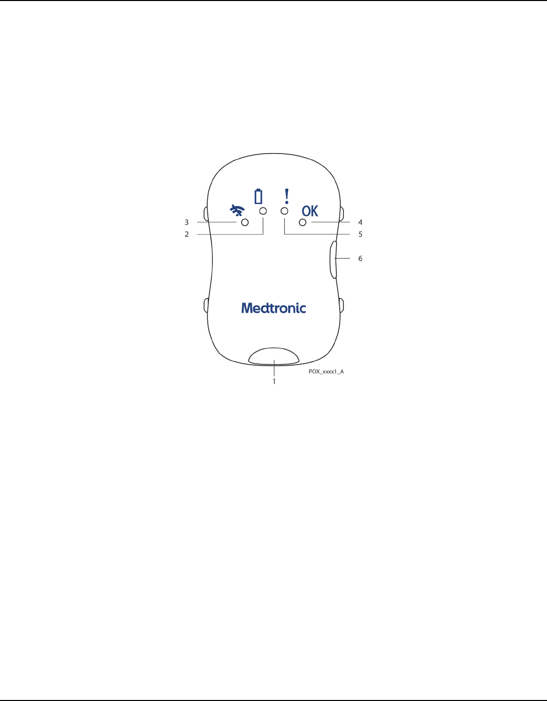
Figure2-1.
Monitoring System Module (top view)
Note:
The visible indicators on the module do not relate to the patient’s physiological condition; they
only show the status of the module and connected sensor.
2.5.2 Module with Connected Sensor
Figure2-2.
||Module with Connected Sensor – graphic pending||
ImageObject
1 Sensor Connector Socket 4 Nominal Condition LED (green)
2 Low Battery LED (orange) 5 Patient Data Error LED (orange)
3 Wireless Connection LED (blue) 6 Power Button
Product Overview
2-4 Operator's Manual
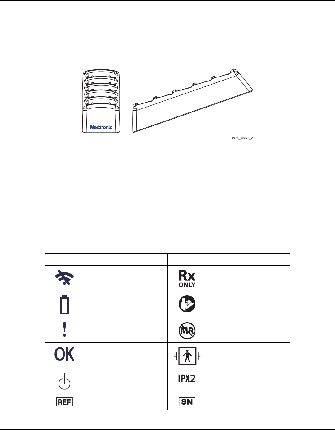
2.5.3 Docking Station
Figure2-3.
Docking Station
2.6 Symbols and Descriptions
This section lists and defines the symbols on the monitoring system module and the
packaging labeling.
2.6.1 Monitoring System Module
Table 2-1 defines the symbols that appear on the monitoring system module.
Table2-2.
Symbols on Module
Symbol Description Symbol Description
Connection error (monitoring
system not connected to external
host).
US federal law restricts this device to
sale by or on the order of a physician.
Module battery charge low (if
module is not docked), or module
battery recharging (if docked).
Follow instructions for use (appears
in blue on the device).
Sensor error or sensor disconnect. Not safe in any magnetic resonance
(MR) environment.
Nominal condition (monitoring
system is operating normally).
Defibrillator-proof type BF applied
part.
Power on / power off. Protection against fluid ingress.
Part number. Serial number.

Symbols and Descriptions
Operator's Manual 2-5
2.6.2 Packaging and Labeling
Table 2-2 defines the symbols that appear on the packaging and package labeling
for the patient components of the monitoring system.
Manufacturer. Date of manufacture.
Canadian and US certification mark. WEEE (Waste from Electrical and
Electronic Equipment)
Table2-2.
Symbols on Module (Continued)
Symbol Description Symbol Description
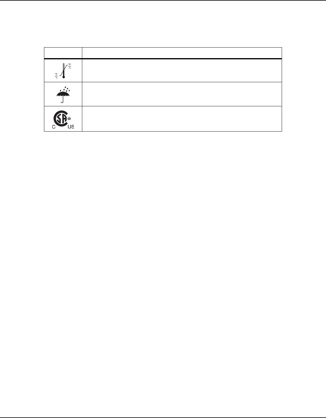
Table2-3.
Symbols on Labeling
Symbol Definition
Part number
Serial number
Manufacturer
Date of manufacture
US federal law restricts this device to sale by or on the order of a physician
Follow instructions for use (appears in blue on the device)
Not safe in any magnetic resonance (MR) environment
Atmospheric pressure limitation.
For upper and lower limits, refer to
Environmental Conditions
on page
8-2
.
Humidity limitation.
For upper and lower limits, refer to
Environmental Conditions
on page
8-2
.
Product Overview
2-6 Operator's Manual
Temperature limitation.
For upper and lower limits, refer to
Environmental Conditions
on page
8-2
.
Keep dry.
Canadian and U.S. certification mark. Products bearing this mark have been tested and certified
in accordance with applicable U.S. and Canadian electrical safety and performance standards.
Table2-3.
Symbols on Labeling (Continued)
Symbol Definition

3-1
3 Docking Station Setup and Operation
3.1 Overview
This chapter describes how to set up and operate the docking station used with the
Vital Sync™ Wearable
SpO
2
Patient Monitoring System.
3.2 Safety Reminders
WARNING:
Electrical shock hazard — Do not soak the docking station or submerge the docking
station into any liquids.
Caution:
To avoid damaging the docking station, do not spray, pour, or spill any liquid directly
onto the docking station, or into any of the sockets.
3.3 Setup
WARNING:
Use only the power cord supplied with the docking station. Do not use any other cord.
To set up the docking station:
1.
Plug the cord from the power supply into the round socket on the docking station.
2.
Plug the power supply into an appropriate AC mains power outlet. If the docking station
is receiving sufficient power for recharging modules, the green LED on the side of the
docking station will light steadily.
Consult with Medtronic Professional Services for more information on configuration
and firmware update procedures; these are beyond the scope of this manual. The
USB port on the docking station is for authorized service use only.

Docking Station Setup and Operation
3-2 Operator's Manual
3.4 Operation
This section details how to use the docking station, including powering the station on
and off and recharging Vital Sync Wearable SpO
2
Patient Monitoring System modules.
3.4.1 Power On and Power Off
The docking station automatically powers on when its power supply is connected and
is plugged into AC power.
The docking station automatically powers off when its power supply is disconnected
or is unplugged from AC power.
The docking station is suitable for continuous AC power operation. Once connected
to AC power, it does not need to be disconnected, except for cleaning and disinfec-
tion.
3.4.2 Module Battery Recharge
Use the docking station to recharge the internal batteries in the Vital Sync Wearable
SpO2 Patient Monitoring System modules.
To prepare the monitoring system for module recharging:
1.
Remove the module and sensor from the patient.
2.
Disconnect the wrist strap and cradle from the module, reversing the procedure used to
attach it. Refer to the wrist strap
Instructions for Use
for details.
3.
Ensure that the module is turned off, then grip the sensor connector (not the connector
cable) and pull straight out to unplug the sensor from the module.
4.
Clean and disinfect the module before recharging. Refer to
Cleaning and Disinfection
on
page
6-1
.
To recharge the module:
1.
Fit the module into an empty socket on the docking station, so that the recharging plug
connects into the module’s sensor connector socket. The socket is shaped to fit the
module casing; do not force the module into the socket.
2.
Check to see that the module’s orange battery LED (which normally indicates a low bat-
tery) starts blinking, which indicates the module is charging. (If this does not happen,
consult
Monitoring System Troubleshooting
on page
7-1
.)

Cleaning and Disinfection
Operator's Manual 3-3
3.
When the orange battery LED stops blinking and is lighted steadily, the battery is
recharged, and the module is ready to be returned to patient use. Remove the module
from the docking station by pulling it out from the socket at the same angle as it is insert-
ed.
Note:
While the module is recharging, it will communicate with the external application to indicate that
it is being recharged, showing the battery’s current charging level. This allows the device to be
viewable in the external application even while charging (it will show as present, but currently
unavailable for patient use).
If the module cannot communicate with the external host, the blue LED will flash to indicate a
connection error; resolve this error as normal (refer to
Monitoring System Troubleshooting
on page
7-1
). However, the module will recharge whether it is able to communicate with the external host
or not.
Note:
Avoid completely discharging the module battery, as this can shorten battery life.
Note:
For best results, allow the battery to recharge completely before reusing the module.
3.5 Cleaning and Disinfection
For details on cleaning and disinfection, refer to Chapter
6
.
3.6 Troubleshooting
If encountering problems with the docking station, refer to
Docking Station Trouble-
shooting
on page
7-3
for possible causes and solutions.

Docking Station Setup and Operation
Page Left Intentionally Blank
3-4 Operator's Manual

4-1
4 Module and Sensor Setup and Operation
4.1 Overview
This chapter describes how to set up and operate the Vital Sync™ Wearable
SpO
2
Patient Monitoring System module and sensor.
Note:
The setup and operation procedures in this chapter only apply to the monitoring system
module and sensor, not to the monitoring application on the external host system. See the
user documentation for the monitoring application for details on how to set up the device in
the application, associate it with a patient, and view device data.
4.2 Safety Reminders
||new draft warning possibly to be added is in blue text||
WARNING:
The monitoring system is intended only as an adjunct in patient assessment. It must be
used in conjunction with clinical signs and symptoms and periodic patient observations.
WARNING:
Tissue damage can be caused by incorrect application or use of a pulse oximetry sensor.
Do not wrap the pulse oximetry sensor too tightly, apply supplemental tape, or leave it
too long on one place. Inspect the pulse oximetry sensor site as directed in the sensor’s
instructions for use to ensure skin integrity, correct positioning, and adhesion.
WARNING:
Discontinue use and dispose of the wrist strap and cradle if the strap or cradle appears to
be stained or becomes excessively moist, to minimize risk of skin irritation.
WARNING:
If skin irritation occurs beneath the wrist strap, discontinue use of the strap.
WARNING:
Do not overtighten the wrist strap, as this can cause patient discomfort, edema, or
pressure injury, or lead to inaccurate sensor readings.

Module and Sensor Setup and Operation
4-2 Operator's Manual
WARNING:
For best product performance and measurement accuracy, use only accessories supplied
or specified by Medtronic. Use accessories according to the manufacturer’s directions for
use and institutional standards.
4.3 Setup
Note:
This procedure is only for placing the module and sensor on the patient. To view monitoring
system data, additional setup is necessary in the monitoring application on the external host
system. Refer to the user documentation for the monitoring application for details.
To set up the monitoring system module and sensor for use on a patient:
1.
Ensure that the module battery is charged. Refer to
Module Battery Recharge
on page
3-2
.
2.
Attach the module to the cradle, which should already be secured to the patient’s wrist
with the wrist strap. Refer to the wrist strap/cradle instructions for use for details.
3.
Plug the sensor connector straight into the connector socket.
4.
Place the sensor on the patient. Refer to the sensor instructions for use for details.
Note:
If the patient is to wear the module and sensor for an extended period, periodically inspect the
patient’s skin for irritation at the sensor site or underneath the wrist strap. If irritation develops,
inspect the strap to determine if it should be replaced, and move the module to a different site.
4.4 Operation
This section details how to use the module and sensor, including powering on and off,
interpreting the device display, and viewing patient data. It also details alarm thresh-
old functionality.
4.4.1 Power On and Power Off
To turn the monitoring system module on, press and hold the on/off button on the
side of the module until all four LEDs flash briefly. The LEDs will then change to indi-
cate the module’s current status.

Operation
Operator's Manual 4-3
If the module’s condition is nominal, the blue LED will blink for a short period until the
module connects with the external host; after this, the green LED will turn on to indi-
cate normal operation.
If any LED or LEDs other than the green LED are lighted, there is a problem. Refer to
Monitoring System Troubleshooting
on page
7-1
for more information.
To turn the monitoring system module off, press and hold the on/off button until all
four LEDs flash briefly, then all turn off.
4.4.2 Monitor a Patient
Once the module is attached to the patient and is powered on, use the LEDs on the
module to view the current status of the module and sensor, and use the monitoring
application to view patient data and alarms.
Note:
The LEDs on the module do not relate to the patient’s physiological condition; they only show
the status of the module and connected sensor.
Note:
The LEDs on the module do not indicate SpO
2
, pulse rate, or SatSeconds alarms. Those alarms are
only visible in the monitoring application.
Device Display
The LEDs on the monitoring system module indicate its current status. See
Table4-1.
Table4-1.
Module LEDs and System Status
Symbol LED Color Description / Normal Functioning
Blue Indicates the status of the connection between the module and the external host
system (connected or trying to connect).
If the monitoring system is functioning normally, this LED flashes briefly on module
power up, then blinks while the module establishes a connection with the external
host, then turns off once the connection is established.
Orange Indicates the module battery charge status (nominal, low, or charging).
When the module is in use on a patient, if the monitoring system is functioning nor-
mally, this LED flashes briefly on module power up, then turns off.
When the module is being recharged, if the docking station is functioning normally,
this LED blinks during charging, then lights steadily when charging is complete.

Module and Sensor Setup and Operation
4-4 Operator's Manual
Any LED state other than those described in Table 3-1 indicates a problem. Refer to
Monitoring System Troubleshooting
on page
7-1
for details on potential problem
causes and solutions.
Note:
LEDs that are lighted will dim slightly after a short period of time. This is a power-saving feature,
and part of the module’s normal operation.
Procedure
To monitor data from a patient:
1.
After completing setup on the patient (as described in
Setup
on page
4-2
), turn the mon-
itoring system module on.
2.
Wait briefly for the module to communicate with and connect to the external host
system. If it does not successfully connect, the blue LED will blink; refer to
Monitoring
System Troubleshooting
on page
7-1
for further steps.
3.
Once the module is communicating with the host system, the blue LED will turn off, and
the green LED will light steadily. This indicates that the sensor is receiving useful data, and
that the module is transferring the data successfully to the host system. (If this does not
happen, refer to
Monitoring System Troubleshooting
on page
7-1
for further steps.)
4.
Ensure that the monitoring application on the external host system shows that the
module is connected, and is showing SpO
2
and pulse rate data for this patient. Refer to
the monitoring application user documentation for details on identifying specific devices
in the application, and for properly associating devices with specific patients.
5.
Continue to monitor the patient according to clinical needs and facility protocols.
Data Transmission
The module transmits SpO
2
and pulse rate data to the external host system once every
minute. Data values for both parameters are averaged across the one-minute interval.
If SpO
2
or pulse rate is outside alarm limits, or if certain other conditions exist, the
module will transmit an alarm indication to the external host within 15 to 30 seconds
Orange Indicates the status of the sensor (operating normally or not).
During normal functioning, this LED flashes briefly on module power up, then turns off.
Green Indicates normal module operation.
During normal functioning, this LED flashes briefly on module power up, then lights
steadily once the module establishes connection with the external host.
Table4-1.
Module LEDs and System Status (Continued)
Symbol LED Color Description / Normal Functioning

Operation
Operator's Manual 4-5
of the onset of the alarm condition. If needed, the module will transmit the alarm indi-
cation again once every 15 to 30 seconds, until the host system acknowledges it. In
this case, the module will transmit the exact value for any parameter in an alarm state
when the alarm was detected, rather than averaging it across the data interval as
normal.
Note:
The speed at which an alarm indication from the module appears in the monitoring application
on the external host can be affected by network loading.
Note:
The monitoring application may allow users to set annunciation delays for SpO
2
and pulse rate
alarms. This will directly affect when alarm indications appear in the monitoring application. Refer
to the application’s user documentation for more information.
Note:
If the module is out of range of the external host system, it will not report monitored data or
alarms to the host system.
Note:
If the module loses connection with the external host, it will continue to monitor data from the
patient. The module will record alarm conditions that occur while it is disconnected or out of
range, and will report them to the monitoring application once it reestablishes connection with
the host system.
4.4.3 Change Alarm Thresholds
The monitoring system module has default thresholds for alarms that are preset on
the device (see
Alarm Thresholds
on page
4-6
). Users may adjust these thresholds in
the monitoring application on the external host system; see the user documentation
for the monitoring application for details.
Once thresholds are adjusted in the application, the application will communicate the
changes to affected modules wirelessly, at the same time that the affected modules
transmit their monitored data to the external host.
Any changes to alarm thresholds will persist on the affected module until changed
again in the application.

Module and Sensor Setup and Operation
4-6 Operator's Manual
4.4.4 Battery Recharge
The module’s internal battery requires periodic recharging using the docking station.
The battery LED indicates whether the module’s battery is low (25% or less of
maximum charge remaining.)
Refer to
Module Battery Recharge
on page
3-2
for recharging steps.
Note:
Avoid completely discharging the module battery, as this can shorten battery life.
Note:
While the module is recharging, it will communicate with the external application to indicate that
it is being recharged, showing the battery’s current charging level. This allows the device to be
viewable in the external application even while charging (it will show as present, but currently
unavailable for patient use).
If the module cannot communicate with the external host, the blue LED will flash to indicate a
connection error; resolve this error as normal (refer to
Monitoring System Troubleshooting
on page
7-1
). However, the module will recharge whether it is able to communicate with the external host
or not.
Note:
For best results, allow the battery to recharge completely before reusing the module.
4.5 Alarm Thresholds
The default alarm thresholds for measured parameters are in
Table4-2.
||to be confirmed vs. project documentation||
Table4-2.
Alarm Threshold Defaults for Vital Sync Wearable Monitoring System
Configurable Parameter Manufacturer Default
Low SpO
2
Threshold 85%
High SpO
2
Threshold 100%
Low Pulse Rate Threshold 40 bpm
High Pulse Rate Threshold 170 bpm
SatSeconds Threshold 100
Pulse Rate Alarm Delay Threshold 10 s

Troubleshooting
Operator's Manual 4-7
If measured values are less than the low threshold values set for SpO
2
or pulse rate, the
monitoring application will indicate an alarm condition.
If measured values are greater than the high threshold values set for SpO
2
or pulse
rate, the monitoring application will indicate an alarm condition.
If measured values exceed the thresholds set for SatSeconds or pulse rate alarm delay,
the monitoring application will indicate an alarm condition.
4.6 Troubleshooting
The module indicates the presence of problems via its LEDs. Depending on which
LEDs are lighted or blinking, more than one problem may be indicated.
Refer to
Monitoring System Troubleshooting
on page
7-1
for possible problem causes
and solutions.

Module and Sensor Setup and Operation
Page Left Intentionally Blank
4-8 Operator's Manual

5-1
5 Performance Considerations
5.1 Overview
This chapter contains information to assist users in optimizing the performance of the
Vital Sync™ Wearable
SpO
2
Patient Monitoring System.
5.2 Oximetry Considerations
5.2.1 Monitoring System Constraints
||to be confirmed vs. project documentation & testing reports||
•
Pulse Rate—
The monitoring system only reports pulse rates between 20 and 250 bpm.
Detected pulse rates above 250 bpm appear as 250. Detected pulse rates below 20
appear as a zero (0).
•
Saturation—
The monitoring system reports saturation levels between 1% and 100%.
Note:
The monitoring application on the external host system displays pulse rate and saturation data.
5.2.2 Sensor Performance Considerations
||draft warning possibly to be added is in blue text||
WARNING:
Do not use the monitoring system if the module or sensor appears or is suspected to be
damaged.
WARNING:
Use only the provided MAXNW sensor with the monitoring system. Connecting any other
sensor influences the accuracy of sensor data, which may lead to inaccurate readings.

Performance Considerations
5-2 Operator's Manual
Note:
Failure to cover the pulse oximetry sensor site with opaque material in high ambient light
conditions may result in inaccurate measurements. Pulse oximetry readings and pulse signals
can be affected by certain environmental conditions, pulse oximetry sensor application errors,
and certain patient conditions. Refer to the appropriate sections of this manual for specific safety
information.
Inaccurate Sensor Measurement Conditions
A variety of conditions can cause inaccurate sensor measurements.
•
Incorrect application of the sensor
•
Placement of the sensor on an extremity with a blood pressure cuff, arterial catheter, or
intravascular line
•
Ambient light
•
Failure to cover the sensor site with opaque material when operating under high ambient
light conditions
•
Excessive patient movement
•
Dark skin pigment
•
Intravascular dyes or externally applied coloring, such as nail polish or pigmented cream
Signal Loss
Loss-of-pulse signal can occur for several reasons.
•
Sensor applied too tightly
•
Inflation of a blood pressure cuff on the same extremity as the attached sensor
•
Arterial occlusion proximal to the sensor
•
Poor peripheral perfusion
Recommended Usage
Apply the provided MAXNW sensor as directed, and observe all warnings and cau-
tions presented in the
Directions for Use
accompanying the sensor. Clean and remove
any substances such as nail polish from the application site. Periodically check to
ensure that the sensor remains properly positioned on the patient.

Patient Conditions
Operator's Manual 5-3
High ambient light sources such as bilirubin lamps, fluorescent lights, infrared heating
lamps, and direct sunlight can interfere with the performance of a sensor. To prevent
interference from ambient light, ensure the sensor is properly applied, and cover the
sensor with opaque material.
If patient movement presents a problem, try one or more of the following remedies
to correct the problem.
•
Verify the sensor is properly and securely applied.
•
Move the sensor to a less active site.
•
Use a new sensor with fresh adhesive backing.
•
Keep the patient still, if possible.
5.3 Patient Conditions
Application issues and certain patient conditions can affect the measurements of the
monitoring system and cause the loss of the pulse signal.
•
Anemia — Anemia causes decreased arterial oxygen content. Although SpO
2
readings
may appear normal, an anemic patient may be hypoxic. Correcting anemia can improve
arterial oxygen content. The monitoring system may fail to provide an SpO
2
reading if
hemoglobin levels fall below 5 gm/dl.
•
Dysfunctional hemoglobins — Dysfunctional hemoglobins such as carboxyhemoglobin,
methemoglobin, and sulfhemoglobin are unable to carry oxygen. SpO
2
readings may
appear normal; however, a patient may be hypoxic because less hemoglobin is available
to carry oxygen. Further assessment beyond pulse oximetry is recommended.
•
Additional possible patient conditions may also influence measurements.
–
Poor peripheral perfusion
–
Excessive patient movement
–
Dark skin pigment
–
Intravascular dyes, such as indocyanine green or methylene blue
–
Externally applied coloring agents (nail polish, dye, pigmented cream)
–
Defibrillation

Performance Considerations
5-4 Operator's Manual
5.4 Reducing Electromagnetic Interference (EMI)
WARNING:
Interference from electrosurgical generators can degrade the performance or accuracy of
the module and sensor.
WARNING:
This monitoring system is intended for use by healthcare professionals only. This
equipment may cause radio interference or may disrupt the operation of nearby
equipment. It may be necessary to take mitigation measures, such as re-orienting or
relocating the monitoring system module or shielding the location.
Because of the proliferation of radio frequency transmitting equipment and other
sources of electrical noise in health care environments (for example, electrosurgical
units, cellular phones, mobile two-way radios, electrical appliances, and high-defini-
tion television), it is possible that high levels of such interference due to close proxim-
ity or strength of a source might result in disruption of monitoring system
performance. Refer to
Electromagnetic Emissions
on page
8-4
.
The monitoring system is designed for use in environments in which electromagnetic
interference might obscure the client’s pulse. During such interference, measure-
ments may seem inappropriate or the monitoring system may not seem to operate
correctly. EMI disruption can cause erratic readings, cessation of operation, or other
incorrect functioning. If this occurs, survey the site of use to determine the source of
this disruption, and take the listed actions to eliminate the source.
•
Turn equipment in the vicinity off and on to isolate the interfering equipment.
•
Reorient or relocate the interfering equipment.
•
Increase the separation between the interfering equipment and the monitoring system.
The monitoring system module generates, uses, and can radiate radio frequency
energy and, if not installed and used in accordance with these instructions, may itself
cause harmful interference with other susceptible devices in the vicinity.

6-1
6 Product Maintenance
6.1 Overview
This chapter describes how to clean, disinfect, and (if necessary) obtain service for the
Vital Sync™ Wearable SpO
2
Patient Monitoring System module and docking station.
6.2 Cleaning and Disinfection
After use on a patient, the module is reusable on the same patient or a different
patient. However, it must be cleaned and disinfected before recharging, and then
cleaned again after recharging, before the next patient use.
WARNING:
The sensor and the wrist strap and cradle are intended for single use only. Do not clean or
disinfect the sensor or the wrist strap and cradle.
6.2.1 Cleaning and Disinfecting Agents
||to be confirmed vs. project documentation & testing reports||
Use any of the following agents for cleaning and disinfection:
•
Ethyl or isopropyl alcohol (70%–90%)
•
Quaternary ammonium germicidal detergent solution (e.g., SaniWipe or PDI Sani-cloth
Plus)
1
•
CaviCide disinfectant (CaviWipes)
1
•
Sodium hypochlorite (8.25% bleach, diluted to 1:10 to 1:100)
•
Phenolic germicidal detergent solution (e.g., Lysol or Reckitte Benckiser)
1
•
Hydrogen peroxide (3% solution)
1. Follow product label for disinfection use dilution.

Product Maintenance
6-2 Operator's Manual
6.2.2 Clean the Module
WARNING:
Electrical shock hazard — Do not soak the monitoring system module or submerge it into
any liquids.
Caution:
To avoid damaging the monitoring system module, do not spray, pour, or spill any liquid
directly onto the module, or into the sensor connector socket.
Note:
Do not clean the monitoring system module while it is turned on and attached to a patient.
Cleaning Materials
||to be confirmed vs. project documentation & testing reports||
For best results, use the following when cleaning the module:
•
Spray bottle containing warm water (tap water is suitable)
•
Cleaning agent (refer to
Cleaning and Disinfecting Agents
on page
6-1
).
•
Paper towels
Cleaning Procedure
||to be confirmed vs. project documentation & testing reports||
To clean the module:
1.
Make sure the module is powered off (no LEDs are lighted).
2.
If the sensor is still connected, unplug it from its socket. Dispose of the sensor according
to facility procedures for disposal of single-patient-use devices.
3.
If the wrist strap and cradle are still in place, disengage them from the module and
dispose of them following facility procedures for single-use devices.
Caution:
Do not spray prepared water or cleaning agents directly onto the module or into the
sensor connector socket during cleaning, as this can damage the module or render it
inoperative.

Cleaning and Disinfection
Operator's Manual 6-3
4.
Moisten (but do not saturate) a paper towel with warm water from the prepared spray
bottle. Remove excess water, as required.
5.
Use the moistened paper towel to soften and loosen any bulky soils on the exterior of the
module, then wipe them off, using back and forth overlapping strokes until the soils are
removed.
6.
Moisten (but do not saturate) another paper towel with prepared cleaning agent. If the
cleaning agent is in a pre-moistened wipe (e.g., CaviWipe), use the wipe as dispensed.
7.
Wipe down all external surfaces of the module, removing all visible soil. Begin at the edges
of the connector socket and work toward the opposite end of the module using back and
forth overlapping strokes, to avoid leaving residual soils in or near the socket.
Note:
Ensure at least 30 seconds of contact time between the prepared cleaning agent and all surfaces
being cleaned.
8.
Moisten (but do not saturate) another paper towel with warm water from the prepared
spray bottle. Remove excess water, as required.
9.
Beginning at the edges of the socket as in step 7 above, wipe down all external surfaces
of the module to remove residual detergent.
10.
Using a dry paper towel, wipe all external surfaces of the module until they are free of
moisture.
11.
Inspect the module for any remaining residual soil. If any residual soil is visible, repeat the
cleaning process.
6.2.3 Disinfect the Module
WARNING:
Electrical shock hazard — Do not soak the monitoring system module or submerge it into
any liquids.
Caution:
To avoid damaging the monitoring system module, do not spray, pour, or spill any liquid
directly onto the module, or into the connector socket.

Product Maintenance
6-4 Operator's Manual
Caution:
Do not sterilize the monitoring system module.
Note:
The module should already have been cleaned before disinfecting. For cleaning instructions,
refer to
Clean the Module
on page
6-2
.
Note:
Do not disinfect the monitoring system module while it is turned on and attached to a patient.
Disinfection Materials
||to be confirmed vs. project documentation & testing reports||
Use the following when disinfecting the module:
•
Disinfecting agent (refer to
Cleaning and Disinfecting Agents
on page
6-1
)
•
Sterile lint-free cloths
•
Purified water
Disinfection Procedure
||to be confirmed vs. project documentation & testing reports||
To disinfect the module:
1.
Make sure the module is powered off (no LEDs are lighted).
Caution:
Do not spray disinfecting agents directly onto the module or into the sensor connector
socket during disinfection, as this can damage the module or render it inoperative.
2.
Moisten (but do not saturate) two sterile lint-free cloths with disinfecting agent. If the dis-
infecting agent is in a pre-moistened wipe (e.g., CaviWipe), have two new wipes ready for
use.
Note:
Ensure at least four minutes of contact time between the disinfecting agent and the surfaces
being disinfected.

Module Battery Recharge
Operator's Manual 6-5
3.
Use one prepared cloth or disinfecting wipe to wipe all exterior surfaces of the module,
using back and forth overlapping strokes. Begin wiping at the edges of the connector
socket and work toward the opposite end of the device.
4.
Use a second prepared cloth or disinfecting wipe to re-wipe all external surfaces of the
module, using back and forth overlapping strokes. Begin wiping at the edges of the con-
nector socket and work toward the opposite end of the device.
5.
Moisten (but do not saturate) a sterile lint-free cloth with purified water. Remove excess
water, as required.
6.
Making sure no liquid enters the connector socket, wipe down all external surfaces,
beginning at the edges of the connector socket as in step 4 above, to remove residual dis-
infectant. Ensure at least 30 seconds of wipe-down time.
7.
Inspect the module for any remaining residual disinfectant. If any residual disinfectant is
visible, repeat steps 5 and 6 of this procedure, using a new sterile lint-free cloth.
8.
Allow the device to dry completely before returning it to patient use.
6.2.4 Clean or Disinfect the Docking Station
WARNING:
Electrical shock hazard — Do not soak the docking station or submerge the docking
station into any liquids.
If the docking station requires cleaning or disinfection, use an appropriate cleaning/
disinfecting agent (refer to
Cleaning and Disinfecting Agents
on page
6-1
).
Clean or disinfect only the plastic exterior casing of the docking station.
6.3 Module Battery Recharge
The module’s internal battery requires periodic recharging. The battery LED indicates
whether the module’s battery is low (25% or less of maximum charge remaining.)
Refer to
Module Battery Recharge
on page
3-2
for the recharging procedure.
Note:
Avoid completely discharging the module battery, as this can shorten battery life.

Product Maintenance
6-6 Operator's Manual
Note:
While the module is recharging, it will communicate with the external application to indicate that
it is being recharged, showing the battery’s current charging level. This allows the device to be
viewable in the external application even while charging (it will show as present, but currently
unavailable for patient use).
If the module cannot communicate with the external host, the blue LED will flash to indicate a
connection error; resolve this error as normal (refer to
Troubleshooting
on page
3-3
). However, the
module will recharge whether it is able to communicate with the external host or not.
Note:
For best results, allow the battery to recharge completely before reusing the module.
Note:
All batteries lose capacity with age. The amount of run time for the monitoring system module
in a low battery condition will vary depending on the age of the battery.
6.4 Service
Neither the Vital Sync Wearable SpO
2
Patient Monitoring System nor the docking
station has any user-serviceable components or accessories.
Do not attempt to open or make any repairs to the module or docking station.
If encountering problems that indicate removal of the module or docking station from
patient use, consult with Medtronic for details on returning the module or docking
station for repair or replacement. Refer to
Obtaining Technical Assistance
on page
1-6
for details.

7-1
7 Troubleshooting
7.1 Overview
This chapter provides troubleshooting information both for the Vital Sync™ Wearable
SpO
2
Patient Monitoring System and for the docking station.
7.2 Monitoring System Troubleshooting
This section lists common problems users may encounter when using the monitoring
system, along with possible causes and solutions.
The monitoring system indicates the presence of problems via its LEDs. If more than
one LED is lighted or blinking, more than one problem may be indicated.
Table7-1.
Monitoring System Troubleshooting
Visual Indicator Problem Indicated Potential Cause Solution
Blue LED blinking. Module has not made a
connection to the exter-
nal host.
Module is in the process of
establishing connection
(e.g., right after it is powered
up).
Wait several seconds to see if the
module establishes a connection.
If the blue LED continues to blink
after several seconds, check for and
eliminate other possible causes for
this problem.
External host system is
unavailable.
Check the external host system to
see that it is powered on and opera-
tional.
Module is out of range of the
external host.
Bring the module back within range
of the external host.
Check for interfering equipment in
the patient care area; if possible,
reorient or move any such equip-
ment to reduce the interference.
Possible module fault. Replace the module with a different
module, and see if the new module
is able to establish a connection.
If the new module successfully con-
nects with the external host, remove
the defective module from patient
use.

Troubleshooting
7-2 Operator's Manual
Orange battery LED
blinking.
Battery charge is low. Battery has less than 25% of
full charge (less than 3 hours
remaining).
Remove the module from the
patient and recharge it. Refer to
Module Battery Recharge
on page
3-
2
.
If the module is recharging, this
behavior is normal; no action is
required.
Orange battery LED
not lighted when
module is charging.
Battery is not charging. Module is not fully plugged
into docking station.
Unplug the module from the
docking station, then plug it back in.
Ensure that the orange battery LED
lights.
Module or module battery
has a fault.
Unplug the module from the socket,
then plug it into a different socket. If
the orange battery LED is not
lighted when plugged into any
socket, but the same LED on a differ-
ent module is lighted when
plugged into the docking station,
remove this module from patient
use.
Orange sensor error
LED lighted steadily.
Module is not receiving
useful sensor data.
Sensor is disconnected from
module.
Check to see that the sensor is fully
plugged into the socket on the
module.
Sensor is not attached to
patient.
Check the sensor site and ensure the
sensor is properly placed.
Sensor is connected and
properly placed, but is not
receiving usable data.
Disconnect the sensor from the
module, then reconnect it.
If disconnecting and reconnecting
the sensor does not resolve this
issue, check the sensor site for any
factors that might interfere with the
sensor, including ambient light.
Refer to
Patient Conditions
on page
5-3
. If any such factors exist, relocate
the sensor.
All LEDs are lighted
steadily at the same
time after module is
powered on.
Power-on self-test error. Fault in module, causing
one or more of the module’s
internal self-tests to fail.
Remove the module from the
patient and replace it with a differ-
ent module.
Remove the defective module from
patient use.
One or more LEDs
does not light when
module is powered
on or off.
LED fault. The LED that is not lighting
is faulty.
Remove the module from the
patient and replace it with a differ-
ent module.
Remove the defective module from
patient use.
Module fault. The module has a fault
causing the affected LED or
LEDs not to light.
Table7-1.
Monitoring System Troubleshooting (Continued)
Visual Indicator Problem Indicated Potential Cause Solution

Docking Station Troubleshooting
Operator's Manual 7-3
7.3 Docking Station Troubleshooting
This section lists common problems users may encounter when using the docking
station, along with possible causes and solutions.
Refer to Table 7-2 for more information.
Note:
If a module or docking station needs to be removed from use, consult with Medtronic for details
on returning the item in question for replacement. Refer to
Obtaining Technical Assistance
on
page
1-6
.
Table7-2.
Docking Station Troubleshooting
Visual Indicator Problem Indicated Potential Cause Solution
Green LED next to
power cord socket
does not light.
Docking station is not
receiving power, or is not
receiving sufficient power
to recharge modules.
Docking station power
supply is not plugged into
AC mains power.
Check to ensure the power supply is
plugged into an appropriate AC
power outlet.
If plugging in the power supply
does not resolve the problem, and
another power outlet is available,
plug the docking station power
cord into it.
Power supply is not plugged
into the docking station.
Check to ensure that the cord from
the power supply is completely and
securely plugged into the docking
station.
Docking station is connect-
ed to a PC via USB cable.
The green LED is designed to not
light when connected to USB.
LED fault. The green LED is faulty. TakeRemove the docking station
from use, even if it is capable of pro-
viding power to connected mod-
ules.
Docking station fault. The docking station has a
fault causing the green LED
not to light.
Orange battery LED on
module not lighted
when module is
charging.
Battery is not charging. Docking station is not gen-
erating power.
Ensure that docking station is
plugged into AC power.
Docking station socket is
faulty.
Unplug the module from the socket,
then plug it into a different socket. If
the orange battery LED lights when
plugged into a different socket,
recharge the module, but remove
and replace the docking station as
soon as possible.

Troubleshooting
Page Left Intentionally Blank
7-4 Operator's Manual

8-1
8 Product Specifications
Note:
Unless otherwise noted, the specifications listed in this chapter are for the Vital Sync™ Wearable
SpO
2
Patient Monitoring System module only.
8.1 Physical Characteristics
||all information in this section to be updated per project documentation & reports||
8.2 Battery
||all information in this section to be updated per project documentation & reports||
Module weight 72.6 g (2.56 oz)
Module dimensions 3.06 in x 1.81 in x 1.00 in
Docking station dimensions ||pending||
Type Lithium ion
Voltage 3.7V TYP, 900mAh
Minimum operating time On first use: 33 hours
After 1 year: 28 hours
After 3 years: 15 hours
Recharge time 3–4 hours to fully recharge from low battery condition
Shelf life Four (4) months for new, fully-charged battery
After four (4) months of storage, module runs 33% of stated battery life
Compliance IEC 62133

Product Specifications
8-2 Operator's Manual
8.3 Environmental Conditions
||all information in this section to be updated per project documentation & reports||
8.3.1 Operating
Module
Docking Station
8.3.2 Transport and Storage
Temperature 5 ºC to 40 ºC (41 ºF to 104 ºF), inclusive
Altitude -500 m to 4,000 m (-1,640 ft to 13,123 ft), inclusive
Atmospheric Pressure 107.5 kPa to 61.6 kPa (31.7 inHg to 18.2 inHg), inclusive
Relative Humidity 15% to 75% (inclusive), non-condensing
Temperature 5 ºC to 40 ºC (41 ºF to 104 ºF), inclusive
Altitude -500 m to 4,000 m (-1,640 ft to 13,123 ft), inclusive
Relative Humidity 15% to 95% (inclusive), non-condensing
Temperature -10 ºC to 45 ºC (14 ºF to 113 ºF), inclusive
Altitude -500 m to 5,572 m (-1,640 ft. to 18,281 ft.), inclusive
Atmospheric Pressure 107.5 kPa to 50 kPa (31.7 in. Hg to 14.8 in. Hg), inclusive
Relative Humidity 15% to 95% non-condensing

Product Compliance
Operator's Manual 8-3
8.4 Product Compliance
||all information in this section to be updated per project documentation & reports||
8.5 Manufacturer’s Declaration and Guidance
||all information in this section to be updated per project documentation & reports||
8.5.1 Electromagnetic Compatibility (EMC)
WARNING:
This monitoring system is intended for use by healthcare professionals only. This
equipment may cause radio interference or may disrupt the operation of nearby
equipment. It may be necessary to take mitigation measures, such as re-orienting or
relocating the monitoring system module or shielding the location.
WARNING:
The use of accessories and sensors other than those specified may result in inaccurate
readings of the monitoring system and increased emission and/or decreased
electromagnetic immunity of the monitoring system.
Equipment Classification IEC/EN 80601-2-61:2011
IEC/EN 60601-1:2005
CAN/CSA C22.2 No. 60601-1:08
ANSI AAMI ES 60601-1:2005
Protection Type Class I (Internally powered)
Degree of Protection Type BF (defibrillator-proof) - Applied part
Mode of Operation Continuous
1
1. The sensor continuously collects data and reports it to the module. The module reports data to the external host system once every minute,
unless an alarm condition exists, in which case it will report to the external host system within 15 to 30 seconds of alarm condition detec-
tion.
Electromagnetic Compatibility IEC 60601-1-2:2007
IEC 60601-1-2:2014
Liquid Ingress IPX2: Protected against harmful effects of dripping water
Degree of Safety Not suitable for use in the presence of flammable anesthetics

Product Specifications
8-4 Operator's Manual
The monitoring system is suitable for prescription use only in the specified electro-
magnetic environments, in accordance with the IEC 60601-1-2:2014 standard. The
monitoring system requires special precautions during installation and operation for
electromagnetic compatibility. In particular, the use of nearby mobile or portable
communications equipment may influence monitoring system performance.
Frequency and Bandwidth for Wireless Connection
Electromagnetic Emissions
Table8-1.
Frequency Band, Output Power, and Modulation Type
Frequency Band (MHz) Output Power
(Watts)
Modulation Type
2412 - 2462 0.088 BPSK, CCK, OFDM
5180 - 5240 0.018 OFDM
5260 - 5320 0.018 OFDM
5500 - 5700 0.028 OFDM
5745 - 5825 0.026 OFDM
Table8-2.
Electromagnetic Emissions Guidelines and Compliance
Guidance and Manufacturer’s Declaration—Electromagnetic Emissions
(IEC/EN 60601-1-2:2014, Table 1)
The monitoring system is intended for use in the electromagnetic environment specified below.
The customer or the user of the monitoring system should assure that it is used in such an environment.
Emissions Test Compliance Electromagnetic Environment Guidance
RF emission
CISPR 11
EN 55011
Class B Not intended for use in a residential environment. If used in a
domestic environment, may not offer adequate protection to
radio-frequency communication services. The user may be
required to take mitigation measures, such as relocating or re-
orienting the equipment.

Manufacturer’s Declaration and Guidance
Operator's Manual 8-5
Electromagnetic Immunity
Table8-3.
Electromagnetic Immunity Guidelines and Compliance
Guidance and Manufacturer’s Declaration—Electromagnetic Immunity
(IEC/EN 60601-1-2:2014, Table 2)
The monitoring system is intended for use in the electromagnetic environment specified below.
The customer or the user of the monitoring system should assure that it is used in such an environment.
Immunity Test IEC/EN 60601-1-2
Test Level
Compliance
Level
Electromagnetic Environment
Guidance
Electrostatic discharge
(ESD)
IEC/EN 61000-4-2
± 6 kV contact
± 8 kV air
± 6 kV contact
± 8 kV air
Floor should be wood, concrete, or
ceramic tile. If floors are covered with
synthetic material, the relative humid-
ity should be at least 30%.
Power frequency (50/60
Hz) magnetic field
IEC/EN 61000-4-8
3 A/m 3 A/m It may be necessary to position further
from the sources of power frequency
magnetic fields or to install magnetic
shielding.
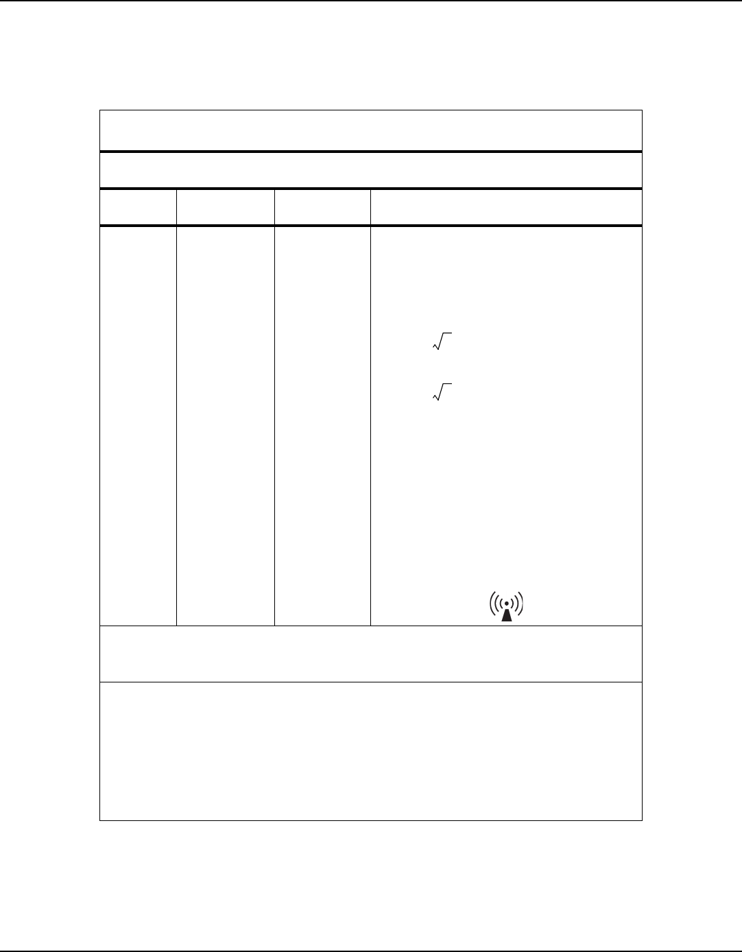
Product Specifications
8-6 Operator's Manual
Table8-4.
Recommended Separation Distance Calculations
Guidance and Manufacturer’s Declaration—Electromagnetic Immunity
(IEC/EN 60601-1-2:2014, Table 4)
The monitoring system is intended for use in the electromagnetic environment specified below.
The customer or the user of the monitoring system should assure that it is used in such an environment.
Immunity
Test
IEC/EN 60601-1-2
Test Level
Compliance
Level
Electromagnetic Environment Guidance
Conducted RF
IEC/EN
61000-4-6
Radiated RF
IEC/EN
61000-4-3
3 Vrms
150 kHz to 80 MHz
3 V/m
80 MHz to 2.5 GHz
10 V/m
80 MHz to 2.5 GHz
3 Vrms
150 kHz to 80 MHz
3 V/m
80 MHz to 2.5 GHz
10 V/m
80 MHz to 2.5 GHz
Portable and mobile RF communications equipment
should be used no closer to any part of the monitoring
system, including cables, than the recommended separa-
tion distance calculated from the equation applicable to
the frequency of the transmitter.
Recommended Separation Distance
80 MHz to 800 MHz
800 MHz to 2.5 GHz
where
P
is the maximum output power rating of the
transmitter in watts (
W
) according to the transmitter
manufacturer and
d
is the recommended separation dis-
tance in meters (
m
).
Field strengths from fixed RF transmitters, as determined
by an electromagnetic site survey
a
, should be less than
the compliance level in each frequency range
b
.
Interference may occur in the vicinity of equipment
marked with the following symbol:
NOTE 1: At 80 MHz and 800 MHz, the higher frequency range applies.
NOTE 2: These guidelines may not apply in all situations. Electromagnetic propagation is affected by absorption and
reflection from structures, objects, and people.
a
Field strengths from fixed transmitters, such as base stations for radio (cellular/cordless) telephones and land
mobile radios, amateur radio, AM and FM radio broadcast and TV broadcast cannot be predicted theoretically with
accuracy. To assess the electromagnetic environment due to fixed RF transmitters, an electromagnetic site survey
should be considered. If the measured field strength in the location in which the monitoring system is used exceeds
the applicable RF compliance level above, the monitoring system should be observed to verify normal operation. If
abnormal performance is observed, additional measures may be necessary, such as re-orienting or relocating the
monitoring system.
b
Over the frequency range 150 kHz to 80 MHz, field strengths should be less than 3 V/m.
d1.2 P=
d2.3 P=
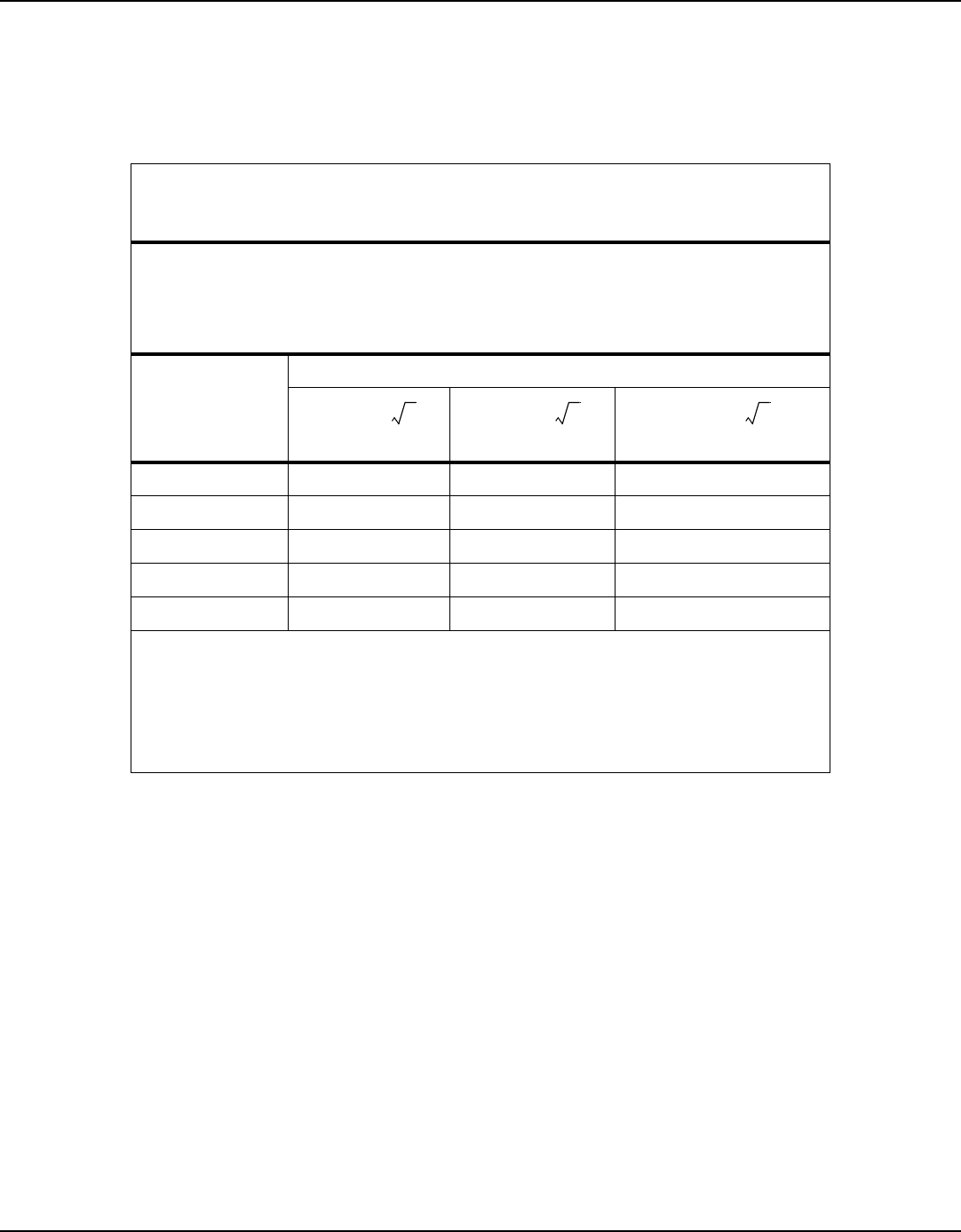
Manufacturer’s Declaration and Guidance
Operator's Manual 8-7
8.5.2 FCC Compliance
This device complies with part 15 of the FCC Rules. Operation is subject to the follow-
ing two conditions: (1) This device may not cause harmful interference, and (2) this
device must accept any interference received, including interference that may cause
undesired operation.
Caution:
Changes or modifications not expressly approved by the party responsible for
compliance could void the user's authority to operate this equipment.
Table8-5.
Recommended Separation Distances
Recommended Separation Distances Between Portable and Mobile RF Communications Equipment and
the Monitoring System
(IEC/EN 60601-1-2:2014, Table 6)
The monitoring system is intended for use in an electromagnetic environment in which radiated RF dis-
turbances are controlled. The customer or the user of the monitoring system can help prevent electro-
magnetic interference by maintaining a minimum distance between portable and mobile RF
communications equipment (transmitters) and the monitoring system as recommended below, accord-
ing to the maximum output power of the communications equipment.
Rated Maximum
Output Power (
P
) of
Transmitter in Watts
Separation Distance According to Frequency of Transmitter in Meters
150 kHz to 80 MHz 80 MHz to 800 MHz 800 MHz to 2.5 GHz
0.01 0.12 0.12 0.23
0.10 0.38 0.38 0.73
1.00 1.20 1.20 2.30
10.00 3.80 3.80 7.30
100.00 12.00 12.00 23.00
For transmitters rated at a maximum output power not listed above, the recommended separation distance (
d
) in
meters (
m
) can be estimated using the equation applicable to the frequency of the transmitter, where
P
is the
maximum output power rating of the transmitter in watts (
W
) according to the transmitter manufacturer.
NOTE 1: At 80 MHz and 800 MHz, the separation distance for the higher frequency range applies.
NOTE 2: These guidelines may not apply in all situations. Electromagnetic propagation is affected by absorption
and reflection from structures, objects, and people.
d1.2 P=
d1.2 P=
d2.3 P=

Product Specifications
8-8 Operator's Manual
8.6 Sensor Accuracy and Ranges
||all information in this section to be updated per project documentation & reports||
This monitoring system has the capability to detect physiological alarm conditions
using SpO
2
accuracy, pulse rate accuracy and alarm limit conditions.
Note:
A functional tester cannot be used to assess the accuracy of the monitoring system or sensor.
Table8-6.
Nellcor™ Sensor Accuracy and Ranges
Measurement Range
SpO
2
1% to 100%
Pulse Rate 20 to 250 beats per minute (bpm)
Accuracy
1
Saturation
Adult
2,
3
70 to 100% ±3 digits
Low Perfusion
4
70 to 100% ±3 digits
Adult with Motion
2, 5
70 to 100% ±3 digits
Pulse Rate
Adult
2, 3
20 to 250 bpm ±5 digits
Low Perfusion
4
20 to 250 bpm ±5 digits
Adult with Motion
2, 5
48 to 127 bpm ±5 digits
1. Saturation accuracy varies by sensor type. Refer to the Sensor Accuracy Grid at www.covidien.com/rms.
2. Accuracy specifications were validated using measurements of healthy non-smoking adult volunteers during controlled hypoxia studies
spanning the specified saturation ranges. Subjects were recruited from the local population and comprised both men and women ranging
in age from 18-50 years old, and spanned a range of skin pigmentations. Pulse oximeter SpO2 readings were compared to SaO2 values of
drawn blood samples measured by hemoximetry. All accuracies are expressed as ±1 SD. Because pulse oximeter equipment measurements
are statistically distributed, about two-thirds of the measurements can be expected to fall in this accuracy (ARMS) range (refer to the Sensor
Accuracy Grid for more details).
3. Adult specifications are shown for OXIMAX MAXNW sensors with the Vital Sync Wearable Patient Monitoring System.
4. Specification applies to Vital Sync Wearable Patient Monitoring System oximeter performance. Reading accuracy in the presence of low per-
fusion (detected IR pulse modulation amplitude 0.1% to 1.5%) was validated using signals supplied by a patient simulator. SpO2 and pulse
rate values were varied across the monitoring range over a range of weak signal conditions and compared to the known true saturation and
pulse rate of the input signals.
5. Motion performance was validated during a controlled hypoxia blood study. Subjects performed rubbing and tapping movements 1-2 cm
in amplitude with aperiodic intervals (randomly changing) with a random variation in frequency between 1-4 Hz. Applicability: OXIMAX
MAXNW sensor.

Essential Performance
Operator's Manual 8-9
8.7 Essential Performance
||all information in this section to be updated per project documentation||
Per IEC 60601-1-2:2007 and ISO 80601-2-61:2011, the monitoring system’s essential
performance attributes include:
•
SpO
2
and pulse rate accuracy —
Refer to
Sensor Accuracy and Ranges
on page
8-8
.
•
Visual indicator of power source —
Refer to
Module
on page
2-3
and
Device Display
on
page
4-3
.
•
Sensor disconnect/off notification —
Refer to
Device Display
on page
4-3
and Table
7-1
on page
7-1
. This information is also sent to the external host system.
•
Motion, interference, or signal degradation indicator —
Refer to Table
7-1
on page
7-
1
. This information is
not
indicated on the device, but only in the monitoring application on
the external host system.
Table8-7.
Nellcor™ Sensor Operating Range and Power Dissipation
Operating Range and Dissipation
Red Light Wavelength Approximately 660 nm
Infrared Light Wavelength Approximately 900 nm
Optical Output Power Less than 15 mW
Power Dissipation 52.5 mW

Product Specifications
Page Left Intentionally Blank
8-10 Operator's Manual

A-1
A Clinical Studies
A.1 Overview
||This appendix will contain clinical study data relevant to the Vital Sync™ Wearable
SpO
2
Patient Monitoring System, once that data is available. Headings below are rep-
resentative.||
A.2 Methods
A.3 Study Population
A.4 Study Results
A.5 Adverse Events or Deviations
A.6 Conclusion

Clinical Studies
Page Left Intentionally Blank
A-2 Operator's Manual

Part No. PT00015629 Rev X05 2016-04
© 2015 Covidien.
Covidien llc
15 Hampshire Street, Mansfield, MA 02048 USA
www.covidien.com [T] 1.800.635.5267