Megavision MV140 LCD Monitor User Manual 140 intro1
Megavision co., Ltd. LCD Monitor 140 intro1
users manual
1
MEGAVISION SYSTEM. Inc
3003 MOTH FIRST STREET SUIT #331
SAN JOSE, CA 95134
TEL : 408-432-5052
FAX : 408-232-5440
TOLL FREE : 080-854-5447
e-mail : techsupport@megavisionsys.com
www.megavisionsys.com
2
TABLE OF CONTENTS
FCC COMPLIANCE STATEMENT NOTE 3
ADJUSTING YOUR LCD MONITOR --------------
• General safety precautions ………………….…………… 4
• Unpacking your monitor ………………………………… 7
• Viewing angle ……………………………………………… 8
• Connecting your monitor ………………………………… 9
• User controls ……………………………………………… 10
• OSD Functions and adjustments ……………….…..……… 11
• Menu adjustments …………………………….…..……… 12
• Refining the picture ………………………….…..……… 14
APPENDIX -----------------------------------
-
• Power management function …………….…..……..…… 15
• Video input terminal ……………………………..……..… 16
• Display modes ………………………………….………… 17
• Troubleshooting …………………………………………… 18
• Option (Pivot function) …………………………………… 20
• Specifications …………………………………………… 21
3
FCC COMPLIANCE STATEMENT
* NOTE :
This equipment has been tested and found to comply with the limits for a
Class B digital device, pursuant to part 15 of the FCC Rules. These limits are
designed to provide reasonable protection against harmful interference in a
residential installation. This equipment generates, uses and can radiate radio
frequency energy and, if not installed and used in accordance with the
instructions, may cause harmful interference to radio communications.
However, there is no guarantee that interference will not occur in a particular
installation. If this equipment does cause harmful interference to radio or
television reception, which can be determined by turning the equipment off
and on, the user is encouraged to try to correct the interference by one or
more of the following measures:
• Reorient or relocate the receiving antenna.
• Increase the separation between the equipment and receiver.
• Connect the equipment into an outlet on a circuit different from that to
which the receiver is connected.
• Consult the dealer or an experienced radio/TV technician for help.
Modifications not expressly approved by the manufacturer could void the
user's authority to operated the equipment under FCC rules.

4
General safety precautions
This Monitor has been engineered and manufactured to assure your safety.
Please read this manual and comply with the warnings and the procedures to
avoid any serious electrical shock and other serious damage.
1.
2.
3.
4.
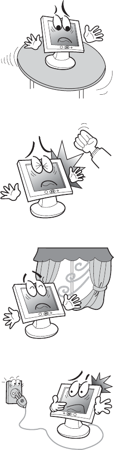
Do not place anything heavy, wet or
magnetic on the monitor or power
cord. Do not cover the ventilation
openings nor touch them with
metallic or flammable material.
High temperature can cause
troubles. Avoid operating the
monitor in extreme heat, humidity
or dusty areas. Extreme temperature
may cause discoloration or dama
g
es.
Ambient Temperature : 0°C ~ 40°C
Do not use a solvent, such as
benzene, to clean the monitor to
prevent any damages to the LCD
surface.
Do not use fine tools such as a pin or
a pencil near the monitor to prevent
any scratch to the LCD surface.
5
5.
6.
7.
8.
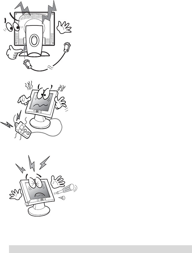
Place the monitor on a flat surface to
prevent it from falling.
Do not apply any mechanical shocks
to the machine.
Install it in a well-ventilated area or
secure enough space for ventilation.
Turn the monitor off before
connecting it to the power outlet.
6
CAUTION : RISK OF ELECTRIC SHOCK, DO NOT OPEN
9.
1
0
.
11.
Make sure that the power cord and
the other cords are properly
connected.
Overloaded AC outlets and extension
cords are dangerous. Also, the frayed
power cords and the broken plugs
may cause electric shock or fire.
Do not open the monitor. There are
no user-serviceable components
inside. There is a risk of exposure to
high-voltage electricity inside, even
when power is turned off. If the
display monitor does not operate
properly, unplug the power cord and
contact your dealer. Handling the
electrical equipment carelessly will
cause a serious electrical shock and
other hazards.
7
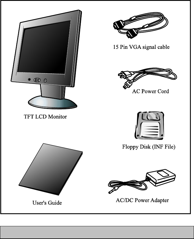
Unpacking your monitor
Please make sure the following items are included with your monitor.
If you find that any of these items are missing or appear damaged, contact
your dealer immediately.
The power cord can be different depending upon different voltage areas.
8
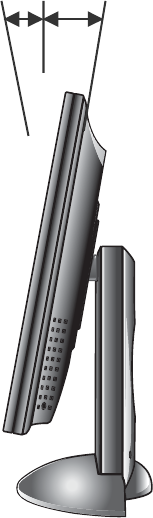
Viewing angle
Your monitor was designed to allow you to adjust it to a
comfortable viewing angle.
The viewing angle can be adjusted 5° to 30° forward and
backward respectively as indicated by the arrow marks below.
5° 30°
9
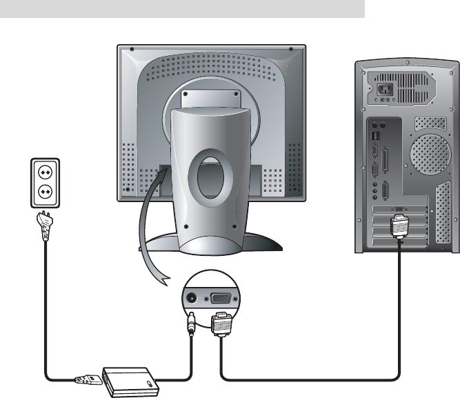
Connecting your monitor
Be sure to turn the computer off before connecting the monitor
g Connect the video signal cable (15Pin connector) to the system’s 15 pin D-sub
connector which is located on the back panel of the computer.
g Connect the power adaptor cord to the monitor and then to the power supply.
g After powering on the computer, adjust the display using the various controls
provided. For further information on the installation procedure, please refer to
the operating guide of the computer being used.
10
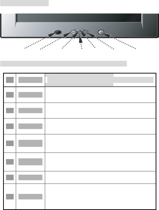
User controls
Front control buttons
LED MENU ADJUST DOWN UP SELECT POWER
No. Key name Description
1 MENU Opens the OSD menu.
2 ADJUST Activates the auto adjustment function.
3 SELECT Selects the main menu items and sub-
menu items.
4 ▲
Moves to the upper menu item or sub-
menu item.
Increases the value of the parameter.
5 ▼
Moves to the lower menu item or sub-
menu item.
Decreases the value of the parameter.
6 POWER Turns on/off the monitor.
7 LED
Indicates the status of the monitor.
• Green : Normal operation.
• Blinking : Power saving mode or
disconnected signal cable.

11
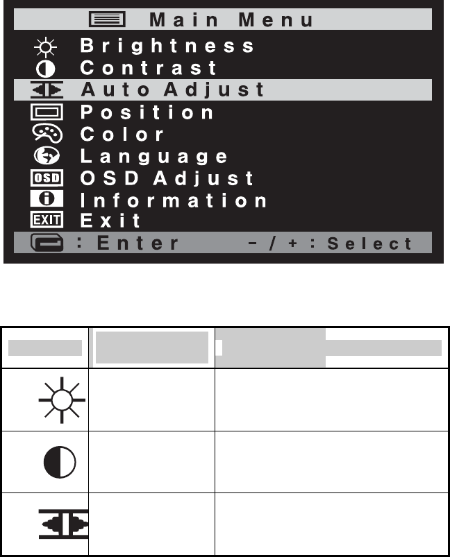
OSD Function and adjustment
Main menu and control selection
Press the MENU key to access the main menu.
The resolution and frequency are displayed at the bottom of the
menu box.
Place the color box on the control icon you wish to adjust by
pressing using the ▼ or ▲ key.
Press the SELECT key to access the control.
Exit menu
Press the MENU key to exit the OSD screen.
Auto exit
The OSD menu will disappear automatically after a few second
of inactivity.
Auto save
The monitor automatically saves the new values when OSD
closes.
Normal mode
When the video signal is working in normal display mode,
power LED is lit green.
DPMS mode
The LED indicates different status when this unit operates in
different power-saving modes.
Out of Range
When an unsuitable signal is detected, the OSD displays an
Out of Range message.
12
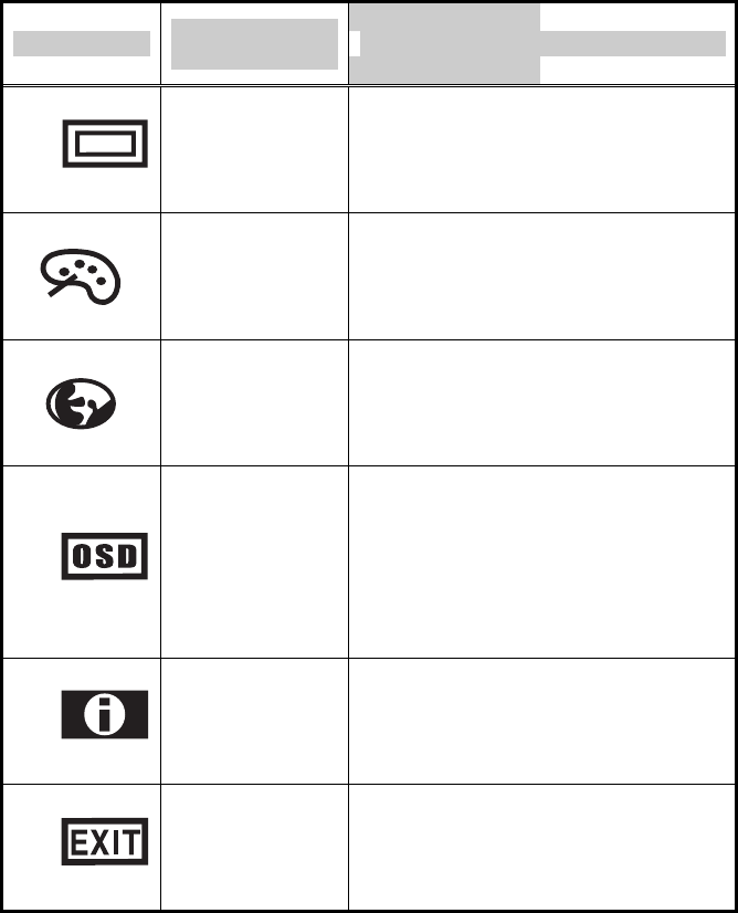
Menu adjustments
Icon Settings and
sub-menus Description
BRIGHTNESS • Adjusts the screen intensity.
CONTRAST • Adjusts the contrast of the screen
image.
AUTO-ADJUST
• Adjusts(automatically) the image
position, the clock and the phase
settings.
13
Icon Settings and
sub-menus Description
POSITION
• Adjusts the horizontal and vertical
position of the screen image.
COLOR
• Displays the color control
menu.
LANGUAGE • Selects from five languages.
OSD ADJUST
• Displays the OSD position
adjustment
for the OSD menu. Selects the
OSD
display timing.
INFORMATION • Information of input timing.
EXIT
• Exits from menus and sub-
menus.
14
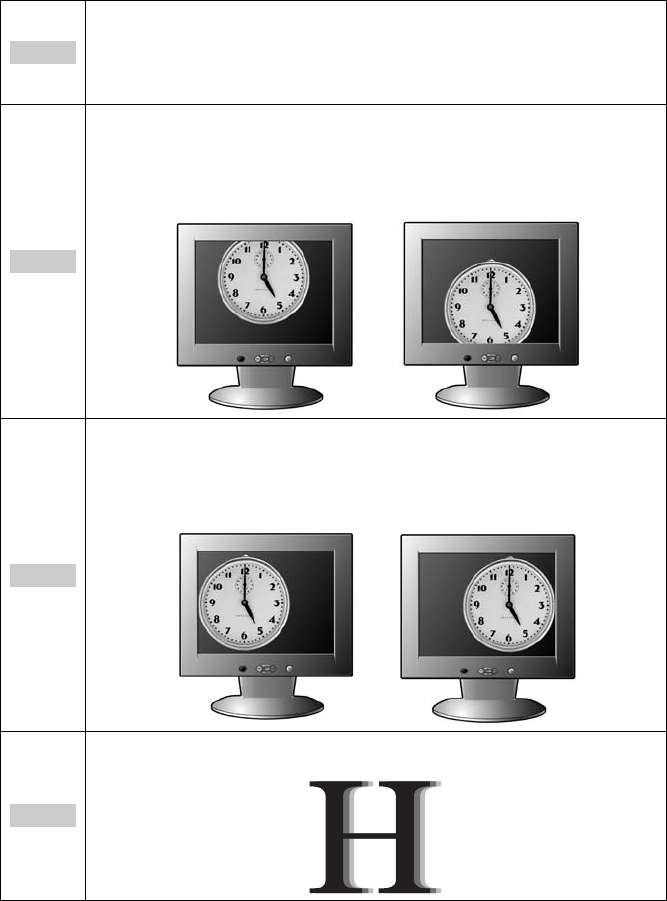
Refining the picture
Step 1
At first display, a full screen, such as window background or
"H" character should be achieved by using editor (eq ;
notepad).
Step 2
Adjust the screen to the center of the display (LCD), by
using the top and bottom display controls (i.e. using Vertical
position menu).
Step 3
Adjust the screen to the center of the display (LCD) by using
the right and left display controls (i.e. using Horizontal position
menu).
Step 4
Adjust the phase until the "H" character displays clear.
15
Step 5
Using the Contrast, Brightness, set the color to your
preference.
Step 6
When you finish the adjustment, you can save your settings
by pressing on the menu until the OSD screen has
disappeared.
Power management function
This monitor is equipped with a DPMS(Display Power
Management Signaling) function that automatically cuts the
power dissipation down to less than 5W when the computer is left
unattended.
Although the monitor can be left in power-saving mode for longer
periods, we recommend that you turn it off after your daily work.
Status Description
Green Power on.
Blink (Amber) Power saving.
Red
Non operating / Abnormal
operating.
16
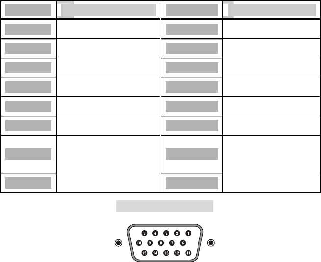
Video input terminal
A 15Pin D-Sub connector is used as the input signal connector.
Each pin and assignment is shown in the table below.
Pin No. Signal Name Pin No. Signal Name
1 RED 9 N.C.
2 GREEN 10 GROUND
3 BLUE 11 GROUND
4 GROUND 12 DDC SDA
5 GROUND 13 H-Sync
6 RED Ground 14 V-Sync
7
GREEN
Ground 15 DDC SCL
8 BLUE Ground
15Pin D-Sub connector
Display modes
For the display modes listed below, the screen image has been
optimized during production.
17
Preset timing modes.
Mode Display
Mode
Horizontal
Frequency (KHz)
Vertical
Frequency (Hz)
Standard Type
640 x
350 31.5KHz 70Hz IBM
720 x
400 31.5KHz 70Hz IBM
640 x
480 31.5KHz 60Hz Industry
Standard
640 x
480 37.9KHz 72Hz VESA
Standard
VGA
640 x
480 37.5KHz 75Hz VESA
Standard
800 x
600 37.9KHz 60Hz VESA
Guidelines
800 x
600 48.1KHz 72Hz VESA
Standard
SVGA
800 x
600 46.9KHz 75Hz VESA
Standard
1024 x
768 48.4KHz 60Hz VESA
Guidelines
1024 x
768 56.5KHz 70Hz VESA
Standard
XGA
1024 x
768 60.0KHz 75Hz VESA
Standard
18
Troubleshooting
Warning : This section will try to anticipate potential problems that you may
encounter in the day-to-day use of your monitor.
If after trying the suggested solutions, your monitor’s symptom
remains the same, contact your authorized service center.
Troubleshooting problems
Problems Corrective Actions
LED ON • Using OSD, adjust Brightness and Contrast to
maximum or reset to their default settings.
LED OFF
• Check the power switch.
• Check if the AC power cord is properly
connected to the AC adapter.
No Picture
LED Blinking
• Check if video signal cable is properly
connected at the back of monitor.
• Check if the power to computer system is
ON.
Display is not clear • Adjust the Frequency and Phase
settings.
Too light or too dark • Adjust the Brightness and Contrast
settings.
Image is not centered • Adjust the Horizontal and Vertical position
settings using the OSD.
Out of Range • Check the maximum resolution and the
frequency on the video port of your computer.
Picture is scrambled • Check the signal cable connection between
the computer and monitor.
19
Problems Corrective Actions
Picture is fuzzy • Perform Auto adjustment.
Picture bounces or has
wavy oscillations
• Check the signal cable connection
between computer and monitor.
Picture appears to be
ghosting
• Check the signal cable connection
between computer and monitor.
Color is not uniform
• Adjust the color settings using the
color menu.
The colors are distorted
with dark or shadowed
areas
• Adjust the color settings using the
color menu.
The power indicator is
blinking Amber
• The monitor is using its power
management system. Check the
power management utility on your
computer.

20
Option
Pivot function
Winportrait installation instruction, WINDOWS 95/98/NT 4.0
1. Quit all the application programs you running.
2. Make sure your graphics card Manufacturer’s (native)
drivers are installed before installing Winportrait software.
3. Insert the pivot CD-ROM into the drive and select RUN from
the START button.
4. Type D:\SETUP.EXE (replace D: with the letter of your CD-
ROM drive if necessary).
5. After reading the license agreement, click agree to install.
6. Additional help message can be accessed by pressing the
‘Help’ button during installation.
7. The english.txt is located on the pivot CD-ROM.
Macportrait installation instructions, MAC/OS
1. Quit all the application programs you running .
2. Insert the pivot CD-ROM into your CD-ROM drive.
3. Double-click on the Macportrait installer and follow the
instructions given on the screen.
21
Specifications
Type • 14.1” viewable diagonal TFT type
Pixel
pitch • 0.297(H) x 0.297(V)mm
LC
D
vie
wa
ble
size
Glass
surface • Anti-Glare, Hard Coating
Viewable angle • L/R : 40°, U/D : 15°/ 30°
Contrast ratio • 250:1 (typical)
Brightness • 150 cd/m2(max)
Resolution • 1024 x 768
Displayable color • 262.144
Frame frequency
(Refresh rate)
• Support range : 56 to 75Hz
• Recommended : 60Hz
User controls
• Auto-Adjust, Brightness, Contrast,
Geometry,
OSD Control, Default-Settings, Fine
Phase, Sharpness
Plug & play • VESA DDC 1/2B
I/O Connectors • DC Power in, VGA 15-pin D-sub
Power • 100~240V
Power consumption
(Max.) • 35W
22
AC/DC Adapter
• Input : Universal AC100 ~ 240V
• Output : DC 12V
• FCC, cUL
Active area • 285.7mm(H) x 214.3mm(V)
Dimensions
(Physical)
• 380mm(W) x 410mm(H) x
150mm(D)
Weight • 4.5Kg