Meko Lighting RF433M LED Strip Light Remote Control User Manual
Meko Lighting Company Limited LED Strip Light Remote Control
User Manual
Indoor LED Flexible Lighting Strip
Important, Retain For Future Reference: READ CAREFULLY
Carefully follow the installation instructions below in order to ensure that this product functions safely
and properly for years to come.
Thank you for selecting DSI as your lighting choice for your home.
With proper care,
this product will provide years of pleasure and enjoyment.
USE & CARE GUIDE
ITM./ART.: 1234762
MODEL: DS18124
MADE IN CHINA
REVISE DATE: 03/28/2017
E
5101 NW 21st Ave, Suite 520, Ft Lauderdale, FL 33309 USA
DSI Customer Service Hotline: 1-800-388-6141 ext. 216 Mon.– Fri., 9:30 a.m. to 3:00 p.m. EST
Customer Service E-mail: CustomerSupport@DSILighting.com
5101 NW 21st Ave, Suite 520, Ft Lauderdale, FL 33309 USA
DSI Customer Service Hotline: 1-800-388-6141 ext. 216 Mon.– Fri., 9:30 a.m. to 3:00 p.m. EST
Customer Service E-mail: CustomerSupport@DSILighting.com
MODEL: DS18124 MODEL: DS18124
120VAC 60Hz
MADE IN CHINA
Page 12 of 12 Page 1 of 12
E
120VAC 60Hz
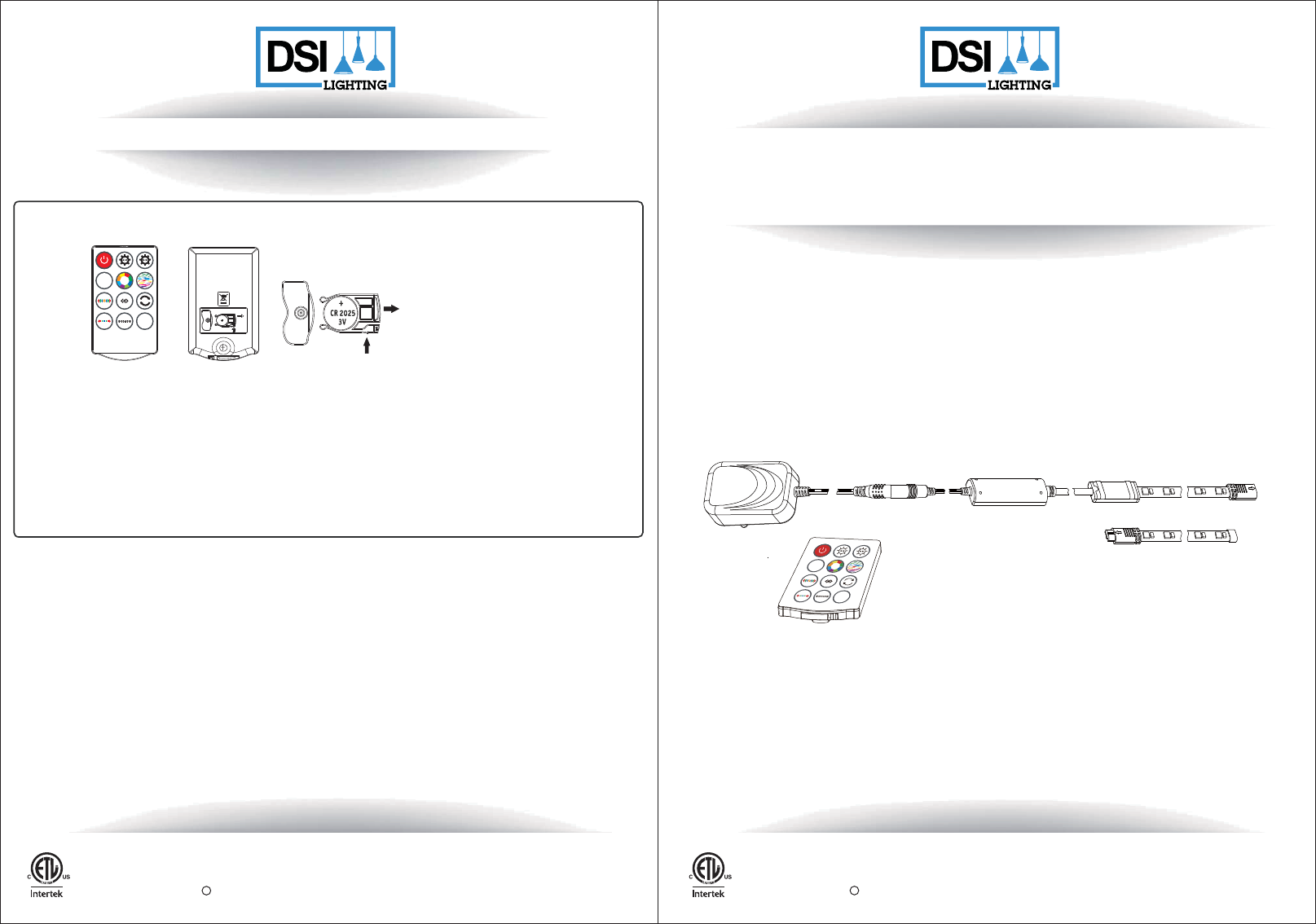
SAFETY INSTRUCTIONS FOR REMOTE
Safety instructions for remote
7
Push
Open
IC Statement
Operation is subject to the following two conditions:
(1) this device may not cause interference, and
(2) this device must accept any interference, including interference that may cause undesired operation of the device.
WARNING: The remote contains a CR2025 DC 3V button battery. If swallowed, it could cause severe injury or death in just 2 hours.
Seek medical attention immediately.
Note: To replace the battery, please loosen the small screw on the back side of the remote, and refer to the diagram on the back side of
the remote.
Always purchase the correct size and grade of battery that is most suitable for the intended use.
Replace all batteries of a set at the same time.
Clean the battery contacts and also those of the device prior to battery installation.
Ensure that batteries are installed correctly with regards to polarity (+ and -).
Remove batteries from equipment when not used for an extended period of time.
Replace used batteries promptly.
WW
Flash
C
WW
Flash
C
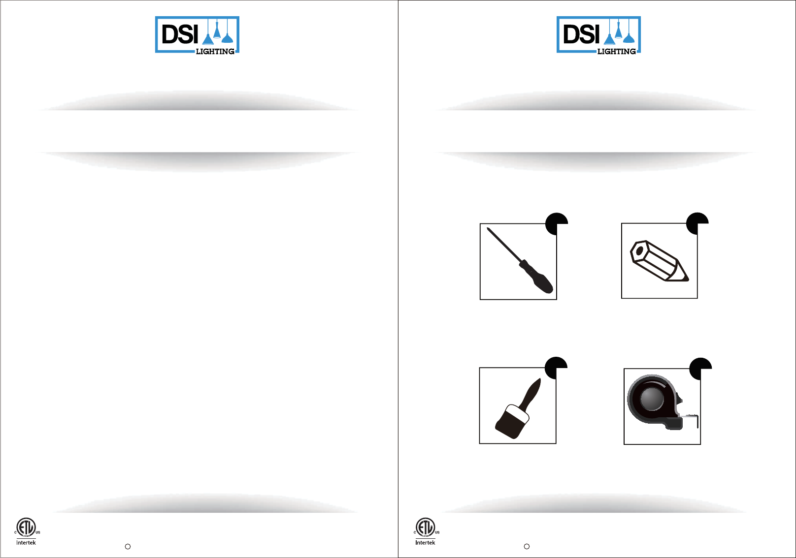
TOOLS NEEDED (not supplied)
Phillips head
screwdriver
Brush
Pencil
E
SAFETY INSTRUCTIONS
1. Important! Main power voltage and fuse must meet the technical data specifications.
Before starting work, ensure that the main cable is not live. Switch off the fuse.
2. Fitting and maintenance work may only be carried out by a professional or an electrician
in accordance with local safety regulations.
3. All electrical connections must have good contact in order for this product to have a long, useful life.
4. LED chips of this LED strip can not be replaced.
5. This LED strip includes a linkable connector. Only link max two LED strips. Do not link more than
two strips together.
6. Please only use LED driver which has been provided with this LED strip.
7. Never use the unit in a room where there is a danger of explosion or in the vicinity of flammable
liquids or gases.
8. Do not bend, crush or pull the cable. Protect from sharp edges, oil and heat.
9. Do not touch the LED strip or electrical connector directly with hands.
10. For indoor use only.
11. Do not use the LED strip on a timer, wall switch with dimming functions, or with an extension cord.
Using the LED strip with any of these voids the warranty and results in the LED strip not
functioning properly. The remote included has dimming functions.
12. Danger of eye damage! Never look directly at the LED chips of this LED strip.
13. Always keep this user manual within reach while installing this LED strip. Please read and
understand the user manual to ensure proper installation and use. Always pay attention to the
technical data shown on the product. We reserve the right to make technical changes.
14. Electrical waste should not be disposed of with household waste. Please recycle where facilities
exist.
15. Warning: The adapter not for use with receptacles that are weatherproof only when the receptacle
is covered (attachment plug cap not inserted and receptacle cover closed).
16. Warning: Risk of electric shock. Mount the adapter at a height greater than 30 cm / 11.8 in. from
the ground surface.
17. Do not submerge any part of this unit.
18. CAUTION: If you choose to modify the length of the LED strip, only cut along the scissors marks.
Please contact DSI Customer Service for further instructions.
Note: Once the LED strip is cut, it will lose the connectable capabilities. You will not be able to
add a new connector or additional strips to the strip that had been cut.
19. Ensure connectors and endcap are securely fastened before operating strip.
20. LED flexible lighting strip rating : 24VDC A.
Safety instructions:
120VAC 60Hz
E
Measuring
tape
120VAC 60Hz
5101 NW 21st Ave, Suite 520, Ft Lauderdale, FL 33309 USA
DSI Customer Service Hotline: 1-800-388-6141 ext. 216 Mon.– Fri., 9:30 a.m. to 3:00 p.m. EST
Customer Service E-mail: CustomerSupport@DSILighting.com
MODEL: DS18124 MADE IN CHINA
Page 2 of 12
5101 NW 21st Ave, Suite 520, Ft Lauderdale, FL 33309 USA
DSI Customer Service Hotline: 1-800-388-6141 ext. 216 Mon.– Fri., 9:30 a.m. to 3:00 p.m. EST
Customer Service E-mail: CustomerSupport@DSILighting.com
MODEL: DS18124 MADE IN CHINA
Page 3 of 12
LED STRIP INSTALLATION
Remove any surface dust from the area where you will be
applying the LED strip.
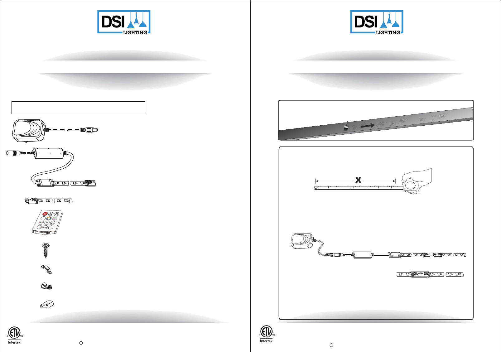
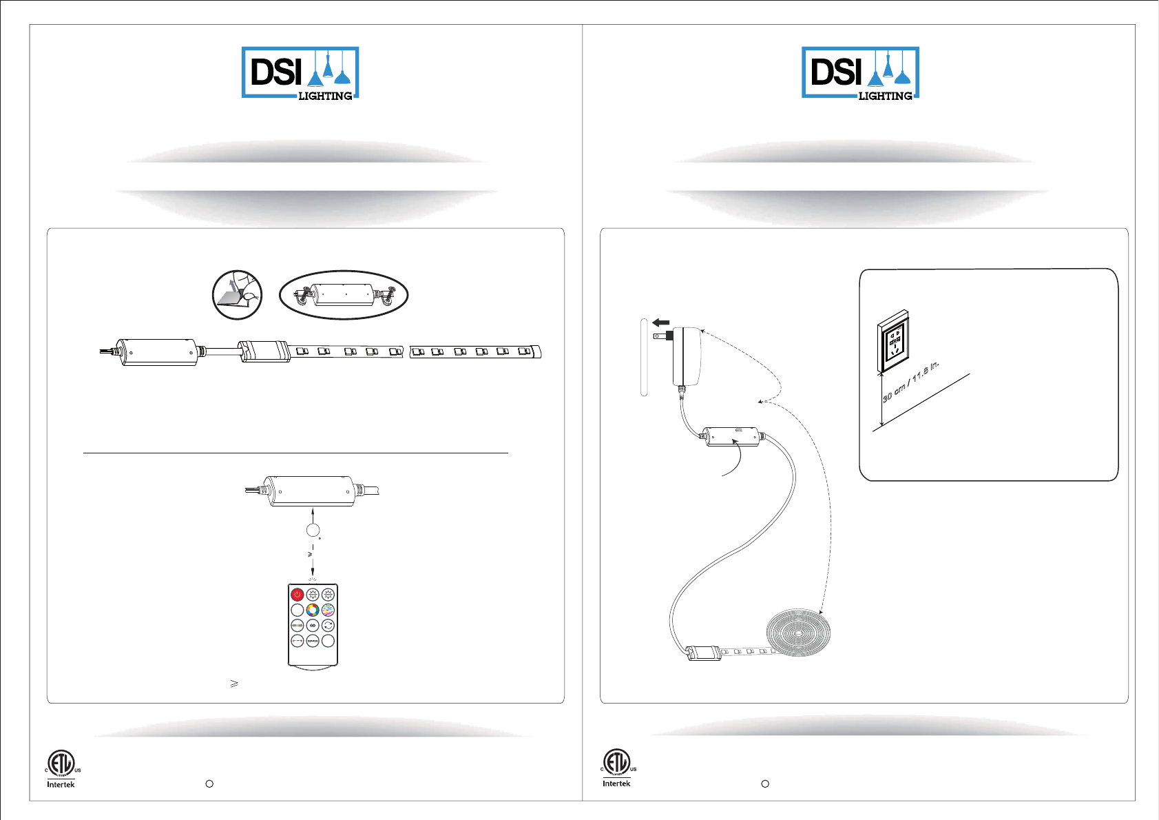
Note: Connect the LED strip (A) to the infrared receiver and adapter by aligning
the arrows on the connector leading from the infrared receiver to the connector
on the LED strip (A). If you require two LED strips, then connect the LED strip (B)
to the end of the LED strip (A) by aligning at the arrows on the connectors. Please
make sure the connectors are securely fastened all the way on both sides.
Note: If you are only using one LED strip for your installation please use LED
strip (A).
Measure the desired space for the LED strip installation to determine if you
need to use one or two strips.
Remote
Adapter
RF receiver and 3.66 m / 12ft 1 set
1 PC
1 PC
Screw
Clip (type MH1)
28 PCS
12 PCS
Wire clip 2 PCS
End cap 1 PCS
PACKAGE CONTENTS
Caution - To prevent personal injury and damage to the LED strip and/or mounting surface, do not pull
the LED strip from the surface. To reduce the likelihood of injury or damage, mount this LED strip only
on a surface that is structurally sound.
Carefully unpack and identify each part to make sure you have everything ready for installation. Lay out
each part on a clean flat area such as a table or carpet. Check to make sure you have the following:
* Parts are not to scale
1
2
120VAC 60Hz
E
E
120VAC 60Hz
(Includes 26 + 2 replacements)
NOTE: All parts and components sold together
in this package can only be used for this model.
3.66 m / 12 ft LED flexible strip (B) 1 set
correct correct
correct
WW
Flash
C
B
A
LED flexible strip (A) as one est
5101 NW 21st Ave, Suite 520, Ft Lauderdale, FL 33309 USA
DSI Customer Service Hotline: 1-800-388-6141 ext. 216 Mon.– Fri., 9:30 a.m. to 3:00 p.m. EST
Customer Service E-mail: CustomerSupport@DSILighting.com
MODEL: DS18124 MADE IN CHINA
Page 4 of 12
5101 NW 21st Ave, Suite 520, Ft Lauderdale, FL 33309 USA
DSI Customer Service Hotline: 1-800-388-6141 ext. 216 Mon.– Fri., 9:30 a.m. to 3:00 p.m. EST
Customer Service E-mail: CustomerSupport@DSILighting.com
MODEL: DS18124 MADE IN CHINA
Page 5 of 12
LED STRIP INSTALLATION LED STRIP INSTALLATION
2 installation options available
4
4A
120VAC 60Hz
EE
120VAC 60Hz
Tape method: Remove the protective tape from the adhesive back of the LED strip carefully.
Place the LED strip into the desired location on a clean and dry surface, and press to ensure
proper adhesion to the surface.
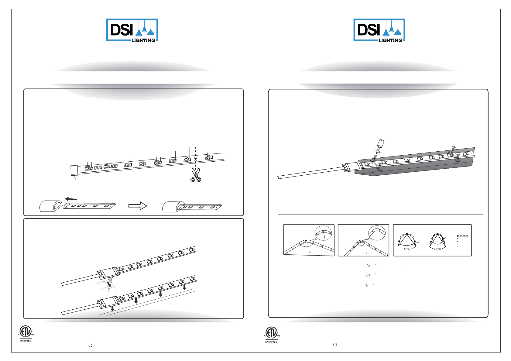
Clip and screw method: Place the LED strip in the desired location. Use the clips and screws
to secure the LED strip as shown. Clips should be placed in open areas of the strip, do not
cover the LED chips.
a.
b. c.
a.: Use an angle greater or equal to 90 degrees when there is an LED chip on the corner while placing
the strip in a concave position. (Angle 90 )
b.: Use an angle greater or equal to 60 degrees when there is no LED chip on the corner while placing
the strip in a concave position. (Angle 60 )
c.: Use an angle greater or equal to 60 degrees when there is an LED chip on the corner while placing
the strip in a convex position. (Angle 60 ) In the convex position the angle should not reach 90
degrees. See above diagram.
Note:
LED Chip
Correct lncorrect lncorrect
Angle 90oAngle 60o
4B
3
Adjusting the length of the strip with scissors
Warranty:
Once the strip is cut, it cannot be reattached.
2. Attach the end cap to the new end. Press the end cap tightly.
End cap Cut line
1 3 5 7 9 11 13
2 4 6 8
10 12
IC
1. Unfold the entire LED strip. Find the end of the LED strip. Each group of twelve LED chips
from the end is considered a complete circuit as shown (each complete circuit has
an IC). You can cut the LED strip at the center of the 12th and 13th LED chip as shown,
along the scissors marks. If you cut the strip on the incorrect point, the remaining LED
chips on the complete circuit will not work.
5101 NW 21st Ave, Suite 520, Ft Lauderdale, FL 33309 USA
DSI Customer Service Hotline: 1-800-388-6141 ext. 216 Mon.– Fri., 9:30 a.m. to 3:00 p.m. EST
Customer Service E-mail: CustomerSupport@DSILighting.com
MODEL: DS18124 MADE IN CHINA
Page 6 of 12
5101 NW 21st Ave, Suite 520, Ft Lauderdale, FL 33309 USA
DSI Customer Service Hotline: 1-800-388-6141 ext. 216 Mon.– Fri., 9:30 a.m. to 3:00 p.m. EST
Customer Service E-mail: CustomerSupport@DSILighting.com
MODEL: DS18124 MADE IN CHINA
Page 7 of 12
LED STRIP INSTALLATION LED STRIP INSTALLATION
Connection to power supply
Note:
6
120VAC 60Hz
E
5a:
5b:
The LED strip and RF receiver is indoor use only.
E
120VAC 60Hz
Warning: Risk of electric
shock. Mount the adapter
at a height greater than
30 cm /
11.8 in. from the
ground surface.
Install the RF receiver
4A 4B
Use the two wire clip to install the RF receiver into desired location.
There are two options for you to choose from:
Remove the protective tape from the adhesive back of the RF receiver carefully, then place the
RF receiver into position and press to ensure a proper adhesion to the surface.
Sensor efficiency distance 15 m / 49.2 ft and sensor efficiency angle about 360°.
CAUTION: Only a maximum of 2 x 3.66 m / 12 ft strips can be linked together using the same adapter.
RF Receiver
Note:
5
4A:
4B:
15 m / 49.2 ft
Connect adapter to power outlet
Adapter
LED strip light
RF receiver
5a
5b
°
360
WW
Flash
C
5101 NW 21st Ave, Suite 520, Ft Lauderdale, FL 33309 USA
DSI Customer Service Hotline: 1-800-388-6141 ext. 216 Mon.– Fri., 9:30 a.m. to 3:00 p.m. EST
Customer Service E-mail: CustomerSupport@DSILighting.com
MODEL: DS18124 MADE IN CHINA
Page 8 of 12
5101 NW 21st Ave, Suite 520, Ft Lauderdale, FL 33309 USA
DSI Customer Service Hotline: 1-800-388-6141 ext. 216 Mon.– Fri., 9:30 a.m. to 3:00 p.m. EST
Customer Service E-mail: CustomerSupport@DSILighting.com
MODEL: DS18124 MADE IN CHINA
Page 9 of 12
E
E
120VAC 60Hz
OPERATING REMOTE
120VAC 60Hz
OPERATING REMOTE
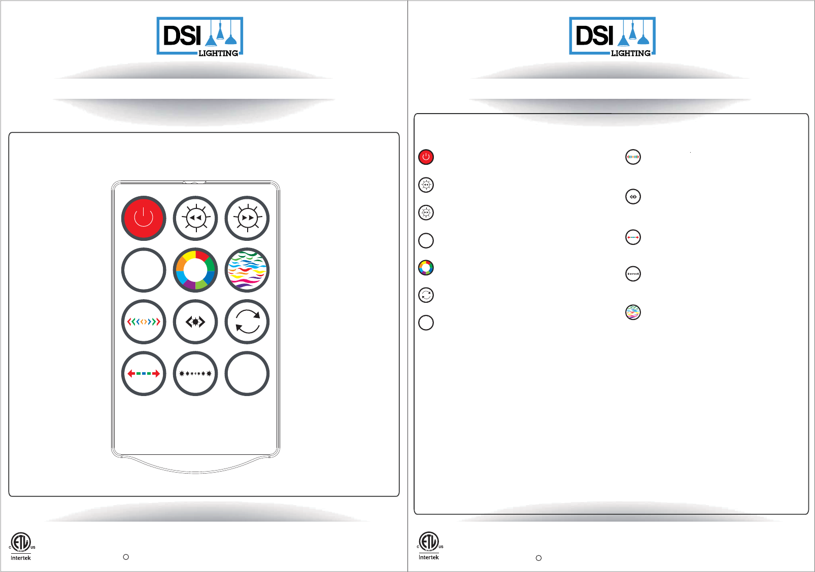
ON/OFF
The remote diagram below is not to scale
7
Functions of Remote
Twelve colours: Eight solid colour options,
Four theme mode: Green theme mode, Blue theme mode,
Orange / Yellow / Red theme mode,
Pink / Purple theme mode
Seven-colour sequence (in stationary or motion mode),
Seasonal lighting (it allows to set the LED strip on the seasonal setting
of your preference - there are 3 options to choose from)
Suggested Operating Method:
Trail - Press this button once to set the Trail chasing feature
into one direction.
Press this button again to set the Trail chasing feature into the
opposite direction.
Choose your preferred colour or colour sequence from the keys
C
Horse Race - Press this button once to set the Horse Race
chasing feature into one direction.
Press this button again to set the Horse Race chasing feature
into the opposite direction.
Choose your preferred colour or colour sequence from the keys
C
Spread - Press this button once to set the Spread chasing
feature into one direction.
Press this button again to set the Spread chasing feature into
the opposite direction.
Choose your preferred colour or colour sequence from the keys
C
Meteor - Press this button once to set the Queued colour chasing
feature into one direction.
Press this button again to set the Queued colour chasing feature
into the opposite direction.
Choose your preferred colour or colour sequence from the keys
C
Continuous multicolour motion
Flash function. Choose your preferred colour or colour sequence
from the keys C
1) First, turn remote on.
2) The simplest operation in RGB colour mode is to make selections in this order: Choose colour, then choose brightness, then choose a motion, and then
choose speed.
3) To set the colour: Select C for colour settings. Select WW for solid white setting.
4) To control brightness, the strip must be in a solid colour state (no motion). For solid white, press WW. For colour, press C. Then press a motion mode
(example trail, horse race, spread, or meteor).
5) To control speed of motion, the strip must be in a motion mode. In RGB mode, press a motion mode (example trail, horse race, spread, flash, or meteor),
and then press the left or right arrow to control the speed of motion. This setting is not available for WW.
6) At any time, it is possible to adjust settings, but brightness must be in a solid colour setting to adjust, and speed must be in a motion setting to adjust.
Increases brightness of the strip in stationary mode.
Increases the speed of the light in the motion mode.
(NOTE: there are 4 light intensity options and 4 speed setting options)
Decreases brightness of the strip in stationary mode.
Decreases the speed of the light in the motion mode.
(NOTE: there are 4 light intensity options and 4 speed setting options)
Flash
Warm white (solid white)
WW
WW
Flash
C
C
5101 NW 21st Ave, Suite 520, Ft Lauderdale, FL 33309 USA
DSI Customer Service Hotline: 1-800-388-6141 ext. 216 Mon.– Fri., 9:30 a.m. to 3:00 p.m. EST
Customer Service E-mail: CustomerSupport@DSILighting.com
MODEL: DS18124 MADE IN CHINA
Page 10 of 12
5101 NW 21st Ave, Suite 520, Ft Lauderdale, FL 33309 USA
DSI Customer Service Hotline: 1-800-388-6141 ext. 216 Mon.– Fri., 9:30 a.m. to 3:00 p.m. EST
Customer Service E-mail: CustomerSupport@DSILighting.com
MODEL: DS18124 MADE IN CHINA
Page 11 of 12
Federal Communications Commission (FCC) Interference Statement
This equipment has been tested and found to comply with the limits for a Class
B digital device, pursuant to Part 15 of the FCC Rules.
These limits are designed to provide reasonable protection against harmful
interference in a residential installation. This equipment generate, uses and
can radiate radio frequency energy and, if not installed and used in
accordance with the instructions, may cause harmful interference to radio
communications.
However, there is no guarantee that interference will not occur in a particular
installation. If this equipment does cause harmful interference to radio or
television reception, which can be determined by turning the equipment off and
on, the user is encouraged to try to correct the interference by one of the
following measures:
Reorient or relocate the receiving antenna.
Increase the separation between the equipment and receiver.
Connect the equipment into an outlet on a circuit different from that to
which the receiver is connected.
Consult the dealer or an experienced radio/TV technician for help.
This device complies with Part 15 of the FCC Rules. Operation is subject to the
following two conditions:
(1) This device may not cause harmful interference, and
(2) this device must accept any interference received, including interference
that may cause undesired operation.
FCC Caution: Any changes or modifications not expressly approved by the
party responsible for compliance could void the user’s authority to operate this
equipment.
RF exposure warning
This equipment complies with FCC radiation exposure limits set forth
for an uncontrolled environment.
This equipment must not be collocated or operating in conjunction with
any other antenna or transmitter.
Industry Canada (IC)
CAN ICES-3 (B)/NMB-3(B)
This device complies with Industry Canada’s licence-exempt RSSs. Operation is subject to the following two
conditions:
(1) This device may not cause harmful interference, and
(2) this device must accept any interference received, including interference that may cause undesired
operation.
Cet appareil est conforme à la norme RSS d'Industrie Canada. Son fonctionnementestsujet aux deux
conditions suivantes:
(1) ledispositif ne doit pas produire de brouillagepréjudiciable, et
(2) cedispositifdoit accepter tout brouillagereçu, y compris un brouillage susceptible de provoquer un
fonctionnementindésirable.