Mentor Fastscan And Flex V8 6 4 Users Manual Reference
v8.6_4 to the manual 23e67613-2cad-48a6-9421-b3f3bb35edef
2015-02-09
: Mentor Mentor-Fastscan-And-Flex-V8-6-4-Users-Manual-554915 mentor-fastscan-and-flex-v8-6-4-users-manual-554915 mentor pdf
Open the PDF directly: View PDF ![]() .
.
Page Count: 831 [warning: Documents this large are best viewed by clicking the View PDF Link!]
- Bookcase
- TABLE OF CONTENTS
- LIST OF FIGURES
- LIST OF TABLES
- About This Manual
- Chapter 1 Introduction
- Chapter 2 Command Dictionary
- Command Summary
- Command Descriptions
- Abort Interrupted Process
- Add Ambiguous Paths
- Add Atpg Constraints
- Add Atpg Functions
- Add Capture Handling
- Add Cell Constraints
- Add Cell Library
- Add Clocks
- Add Cone Blocks
- Add Control Points
- Add Display Instances
- Add Display Loop
- Add Display Path
- Add Display Scanpath
- Add Faults
- Add Iddq Constraints
- Add Initial States
- Add LFSR Connections
- Add LFSR Taps
- Add LFSRs
- Add Lists
- Add Mos Direction
- Add Net Property
- Add Nofaults
- Add Nonscan Handling
- Add Notest Points
- Add Observe Points
- Add Output Masks
- Add Pin Constraints
- Add Pin Equivalences
- Add Pin Strobes
- Add Primary Inputs
- Add Primary Outputs
- Add Random Weights
- Add Read Controls
- Add Scan Chains
- Add Scan Groups
- Add Scan Instances
- Add Scan Models
- Add Slow Pad
- Add Tied Signals
- Add Write Controls
- Analyze Atpg Constraints
- Analyze Bus
- Analyze Control
- Analyze Control Signals
- Analyze Drc Violation
- Analyze Fault
- Analyze Observe
- Analyze Race
- Analyze Restrictions
- Close Schematic Viewer
- Compress Patterns
- Create Initialization Patterns
- Create Patterns
- Delete Atpg Constraints
- Delete Atpg Functions
- Delete Capture Handling
- Delete Cell Constraints
- Delete Clocks
- Delete Cone Blocks
- Delete Control Points
- Delete Display Instances
- Delete Faults
- Delete Iddq Constraints
- Delete Initial States
- Delete LFSR Connections
- Delete LFSR Taps
- Delete LFSRs
- Delete Lists
- Delete Mos Direction
- Delete Net Property
- Delete Nofaults
- Delete Nonscan Handling
- Delete Notest Points
- Delete Observe Points
- Delete Output Masks
- Delete Paths
- Delete Pin Constraints
- Delete Pin Equivalences
- Delete Pin Strobes
- Delete Primary Inputs
- Delete Primary Outputs
- Delete Random Weights
- Delete Read Controls
- Delete Scan Chains
- Delete Scan Groups
- Delete Scan Instances
- Delete Scan Models
- Delete Slow Pad
- Delete Tied Signals
- Delete Write Controls
- Diagnose Failures
- Dofile
- Exit
- Extract Subckts
- Flatten Model
- Flatten Subckt
- Help
- Insert Testability
- Load Faults
- Load Paths
- Macrotest
- Mark
- Open Schematic Viewer
- Read Modelfile
- Read Procfile
- Read Subckts Library
- Redo Display
- Report Aborted Faults
- Report Atpg Constraints
- Report Atpg Functions
- Report AU Faults
- Report Bus Data
- Report Capture Handling
- Report Cell Constraints
- Report Clocks
- Report Cone Blocks
- Report Control Data
- Report Control Points
- Report Core Memory
- Report Display Instances
- Report Drc Rules
- Report Environment
- Report Failures
- Report Faults
- Report Feedback Paths
- Report Flatten Rules
- Report Gates
- Report Hosts
- Report Id Stamp
- Report Iddq Constraints
- Report Initial States
- Report LFSR Connections
- Report LFSRs
- Report Lists
- Report Loops
- Report Mos Direction
- Report Net Properties
- Report Nofaults
- Report Nonscan Cells
- Report Nonscan Handling
- Report Notest Points
- Report Observe Data
- Report Observe Points
- Report Output Masks
- Report Paths
- Report Pin Constraints
- Report Pin Equivalences
- Report Pin Strobes
- Report Primary Inputs
- Report Primary Outputs
- Report Procedure
- Report Pulse Generators
- Report Random Weights
- Report Read Controls
- Report Scan Cells
- Report Scan Chains
- Report Scan Groups
- Report Scan Instances
- Report Scan Models
- Report Seq_transparent Procedures
- Report Slow Pads
- Report Statistics
- Report Test Stimulus
- Report Testability Data
- Report Tied Signals
- Report Timeplate
- Report Version Data
- Report Write Controls
- Reset Au Faults
- Reset State
- Resume Interrupted Process
- Run
- Save Flattened Model
- Save Patterns
- Save Schematic
- Select Iddq Patterns
- Select Object
- Set Abort Limit
- Set Atpg Compression
- Set Atpg Limits
- Set Atpg Window
- Set AU Analysis
- Set Bist Initialization
- Set Bus Handling
- Set Bus Simulation
- Set Capture Clock
- Set Capture Handling
- Set Capture Limit
- Set Checkpoint
- Set Clock Restriction
- Set Clock_off Simulation
- Set Clockpo Patterns
- Set Contention Check
- Set Control Threshold
- Set Decision Order
- Set Dofile Abort
- Set Drc Handling
- Set Driver Restriction
- Set Fails Report
- Set Fault Mode
- Set Fault Sampling
- Set Fault Type
- Set Flatten Handling
- Set Gate Level
- Set Gate Report
- Set Hypertrophic Limit
- Set Iddq Checks
- Set Iddq Strobe
- Set Instancename Visibility
- Set Instruction Atpg
- Set Internal Fault
- Set Internal Name
- Set Interrupt Handling
- Set IO Mask
- Set Learn Report
- Set List File
- Set Logfile Handling
- Set Loop Handling
- Set Multiple Load
- Set Net Dominance
- Set Net Resolution
- Set Nonscan Model
- Set Number Shifts
- Set Observation Point
- Set Observe Threshold
- Set Output Comparison
- Set Output Mask
- Set Pathdelay Holdpi
- Set Pattern Source
- Set Possible Credit
- Set Procedure Cycle_checking
- Set Pulse Generators
- Set Race Data
- Set Rail Strength
- Set Ram Initialization
- Set Ram Test
- Set Random Atpg
- Set Random Clocks
- Set Random Patterns
- Set Random Weights
- Set Redundancy Identification
- Set Schematic Display
- Set Screen Display
- Set Self Initialization
- Set Sensitization Checking
- Set Sequential Learning
- Set Shadow Check
- Set Simulation Mode
- Set Skewed Load
- Set Split Capture_cycle
- Set Stability Check
- Set Static Learning
- Set Stg Extraction
- Set System Mode
- Set Test Cycle
- Set Trace Report
- Set Transition Holdpi
- Set Unused Net
- Set Workspace Size
- Set Xclock Handling
- Set Z Handling
- Set Zhold Behavior
- Set Zoom Factor
- Setup Checkpoint
- Setup LFSRs
- Setup Pin Constraints
- Setup Pin Strobes
- Setup Tied Signals
- Step
- System
- Undo Display
- Unmark
- Unselect Object
- Update Implication Detections
- View
- View Area
- Write Core Memory
- Write Environment
- Write Failures
- Write Faults
- Write Initial States
- Write Library_verification Setup
- Write Loops
- Write Modelfile
- Write Netlist
- Write Paths
- Write Primary Inputs
- Write Primary Outputs
- Write Procfile
- Write Statistics
- Write Timeplate
- Zoom In
- Zoom Out
- Chapter 3 Shell Commands
- Chapter 4 Test Pattern File Formats
- Chapter 5 Distributed FlexTest
- Appendix A Timing Command Dictionary
- Appendix B FlexTest WDB Translation Support
- INDEX
- Send us feedback

FastScan and FlexTest
Reference Manual
Software Version V8.6_4
Copyright Mentor Graphics Corporation 1991—1999. All rights reserved.
This document contains information that is proprietary to Mentor Graphics Corporation and may be
duplicated in whole or in part by the original recipient for internal business purposes only, provided that this
entire notice appears in all copies. In accepting this document, the recipient agrees to make every
reasonable effort to prevent the unauthorized use of this information.

This document is for information and instruction purposes. Mentor Graphics reserves the right to make
changes in specifications and other information contained in this publication without prior notice, and the
reader should, in all cases, consult Mentor Graphics to determine whether any changes have been
made.
The terms and conditions governing the sale and licensing of Mentor Graphics products are set forth in
written agreements between Mentor Graphics and its customers. No representation or other affirmation
of fact contained in this publication shall be deemed to be a warranty or give rise to any liability of Mentor
Graphics whatsoever.
MENTOR GRAPHICS MAKES NO WARRANTY OF ANY KIND WITH REGARD TO THIS MATERIAL
INCLUDING, BUT NOT LIMITED TO, THE IMPLIED WARRANTIES OR MERCHANTABILITY AND
FITNESS FOR A PARTICULAR PURPOSE.
MENTOR GRAPHICS SHALL NOT BE LIABLE FOR ANY INCIDENTAL, INDIRECT, SPECIAL, OR
CONSEQUENTIAL DAMAGES WHATSOEVER (INCLUDING BUT NOT LIMITED TO LOST PROFITS)
ARISING OUT OF OR RELATED TO THIS PUBLICATION OR THE INFORMATION CONTAINED IN IT,
EVEN IF MENTOR GRAPHICS CORPORATION HAS BEEN ADVISED OF THE POSSIBILITY OF
SUCH DAMAGES.
RESTRICTED RIGHTS LEGEND 03/97
U.S. Government Restricted Rights. The SOFTWARE and documentation have been developed
entirely at private expense and are commercial computer software provided with restricted rights. Use,
duplication or disclosure by the U.S. Government or a U.S. Government subcontractor is subject to the
restrictions set forth in the license agreement provided with the software pursuant to DFARS 227.7202-
3(a) or as set forth in subparagraph (c)(1) and (2) of the Commercial Computer Software - Restricted
Rights clause at FAR 52.227-19, as applicable.
Contractor/manufacturer is:
Mentor Graphics Corporation
8005 S.W. Boeckman Road, Wilsonville, Oregon 97070-7777.
A complete list of trademark names appears in a separate “Trademark Information” document.
This is an unpublished work of Mentor Graphics Corporation.

Table of Contents
FastScan and FlexTest Reference Manual, V8.6_4 iii
About This Manual .............................................................................................xvii
Overview.............................................................................................................xvii
Related Publications ............................................................................................xix
Mentor Graphics Documentation......................................................................xix
Acronyms Used in This Manual..........................................................................xxi
Command Line Syntax Conventions................................................................ xxiii
Chapter 1
Introduction ......................................................................................................... 1-1
Features............................................................................................................... 1-1
Inputs and Outputs.............................................................................................. 1-2
Chapter 2
Command Dictionary.......................................................................................... 2-1
Command Summary ........................................................................................... 2-1
Command Descriptions .................................................................................... 2-27
Abort Interrupted Process .............................................................................. 2-28
Add Ambiguous Paths.................................................................................... 2-29
Add Atpg Constraints..................................................................................... 2-31
Add Atpg Functions ....................................................................................... 2-36
Add Capture Handling ................................................................................... 2-40
Add Cell Constraints...................................................................................... 2-43
Add Cell Library ............................................................................................ 2-46
Add Clocks..................................................................................................... 2-47
Add Cone Blocks ........................................................................................... 2-49
Add Control Points......................................................................................... 2-51
Add Display Instances.................................................................................... 2-53
Add Display Loop.......................................................................................... 2-57
Add Display Path ........................................................................................... 2-60
Add Display Scanpath.................................................................................... 2-63
Add Faults ...................................................................................................... 2-66
Add Iddq Constraints ..................................................................................... 2-68
Add Initial States............................................................................................ 2-70
TABLE OF CONTENTS

TABLE OF CONTENTS [continued]
Table of Contents
FastScan and FlexTest Reference Manual, V8.6_4
iv
Add LFSR Connections ................................................................................. 2-72
Add LFSR Taps.............................................................................................. 2-74
Add LFSRs..................................................................................................... 2-76
Add Lists ........................................................................................................ 2-79
Add Mos Direction......................................................................................... 2-81
Add Net Property ........................................................................................... 2-83
Add Nofaults .................................................................................................. 2-84
Add Nonscan Handling.................................................................................. 2-87
Add Notest Points .......................................................................................... 2-89
Add Observe Points........................................................................................ 2-90
Add Output Masks ......................................................................................... 2-92
Add Pin Constraints ....................................................................................... 2-93
Add Pin Equivalences .................................................................................... 2-98
Add Pin Strobes............................................................................................ 2-101
Add Primary Inputs...................................................................................... 2-103
Add Primary Outputs ................................................................................... 2-105
Add Random Weights.................................................................................. 2-106
Add Read Controls....................................................................................... 2-108
Add Scan Chains.......................................................................................... 2-110
Add Scan Groups ......................................................................................... 2-112
Add Scan Instances ...................................................................................... 2-114
Add Scan Models ......................................................................................... 2-115
Add Slow Pad............................................................................................... 2-116
Add Tied Signals.......................................................................................... 2-117
Add Write Controls...................................................................................... 2-119
Analyze Atpg Constraints ............................................................................ 2-120
Analyze Bus ................................................................................................. 2-123
Analyze Control ........................................................................................... 2-126
Analyze Control Signals .............................................................................. 2-128
Analyze Drc Violation ................................................................................. 2-131
Analyze Fault ............................................................................................... 2-137
Analyze Observe .......................................................................................... 2-143
Analyze Race ............................................................................................... 2-145
Analyze Restrictions .................................................................................... 2-147
Close Schematic Viewer .............................................................................. 2-148

TABLE OF CONTENTS [continued]
Table of Contents
FastScan and FlexTest Reference Manual, V8.6_4 v
Compress Patterns........................................................................................ 2-149
Create Initialization Patterns........................................................................ 2-152
Create Patterns ............................................................................................. 2-154
Delete Atpg Constraints ............................................................................... 2-156
Delete Atpg Functions.................................................................................. 2-158
Delete Capture Handling.............................................................................. 2-160
Delete Cell Constraints ................................................................................ 2-162
Delete Clocks ............................................................................................... 2-164
Delete Cone Blocks...................................................................................... 2-165
Delete Control Points ................................................................................... 2-167
Delete Display Instances.............................................................................. 2-169
Delete Faults................................................................................................. 2-171
Delete Iddq Constraints................................................................................ 2-174
Delete Initial States ...................................................................................... 2-176
Delete LFSR Connections............................................................................ 2-177
Delete LFSR Taps........................................................................................ 2-179
Delete LFSRs ............................................................................................... 2-181
Delete Lists................................................................................................... 2-183
Delete Mos Direction ................................................................................... 2-184
Delete Net Property...................................................................................... 2-185
Delete Nofaults............................................................................................. 2-186
Delete Nonscan Handling ............................................................................ 2-189
Delete Notest Points..................................................................................... 2-191
Delete Observe Points.................................................................................. 2-193
Delete Output Masks.................................................................................... 2-195
Delete Paths.................................................................................................. 2-197
Delete Pin Constraints.................................................................................. 2-199
Delete Pin Equivalences............................................................................... 2-201
Delete Pin Strobes........................................................................................ 2-202
Delete Primary Inputs .................................................................................. 2-204
Delete Primary Outputs................................................................................ 2-206
Delete Random Weights .............................................................................. 2-208
Delete Read Controls ................................................................................... 2-210
Delete Scan Chains ...................................................................................... 2-211
Delete Scan Groups...................................................................................... 2-212

TABLE OF CONTENTS [continued]
Table of Contents
FastScan and FlexTest Reference Manual, V8.6_4
vi
Delete Scan Instances................................................................................... 2-214
Delete Scan Models...................................................................................... 2-215
Delete Slow Pad ........................................................................................... 2-216
Delete Tied Signals ...................................................................................... 2-217
Delete Write Controls .................................................................................. 2-219
Diagnose Failures......................................................................................... 2-220
Dofile............................................................................................................ 2-224
Exit ............................................................................................................... 2-226
Extract Subckts............................................................................................. 2-227
Flatten Model ............................................................................................... 2-228
Flatten Subckt............................................................................................... 2-229
Help.............................................................................................................. 2-230
Insert Testability........................................................................................... 2-232
Load Faults................................................................................................... 2-234
Load Paths.................................................................................................... 2-238
Macrotest...................................................................................................... 2-242
Mark ............................................................................................................. 2-248
Open Schematic Viewer............................................................................... 2-250
Read Modelfile............................................................................................. 2-252
Read Procfile................................................................................................ 2-255
Read Subckts Library................................................................................... 2-256
Redo Display................................................................................................ 2-257
Report Aborted Faults.................................................................................. 2-259
Report Atpg Constraints............................................................................... 2-262
Report Atpg Functions ................................................................................. 2-263
Report AU Faults ......................................................................................... 2-264
Report Bus Data ........................................................................................... 2-268
Report Capture Handling ............................................................................. 2-272
Report Cell Constraints................................................................................ 2-274
Report Clocks............................................................................................... 2-276
Report Cone Blocks ..................................................................................... 2-277
Report Control Data ..................................................................................... 2-278
Report Control Points................................................................................... 2-280
Report Core Memory ................................................................................... 2-281
Report Display Instances.............................................................................. 2-282

TABLE OF CONTENTS [continued]
Table of Contents
FastScan and FlexTest Reference Manual, V8.6_4 vii
Report Drc Rules.......................................................................................... 2-285
Report Environment..................................................................................... 2-293
Report Failures............................................................................................. 2-295
Report Faults ................................................................................................ 2-298
Report Feedback Paths................................................................................. 2-303
Report Flatten Rules..................................................................................... 2-305
Report Gates................................................................................................. 2-309
Report Hosts................................................................................................. 2-326
Report Id Stamp ........................................................................................... 2-327
Report Iddq Constraints ............................................................................... 2-329
Report Initial States...................................................................................... 2-331
Report LFSR Connections ........................................................................... 2-333
Report LFSRs............................................................................................... 2-334
Report Lists .................................................................................................. 2-335
Report Loops................................................................................................ 2-336
Report Mos Direction................................................................................... 2-337
Report Net Properties................................................................................... 2-338
Report Nofaults ............................................................................................ 2-339
Report Nonscan Cells................................................................................... 2-341
Report Nonscan Handling............................................................................ 2-345
Report Notest Points .................................................................................... 2-346
Report Observe Data.................................................................................... 2-347
Report Observe Points.................................................................................. 2-349
Report Output Masks ................................................................................... 2-350
Report Paths ................................................................................................. 2-351
Report Pin Constraints ................................................................................. 2-353
Report Pin Equivalences .............................................................................. 2-355
Report Pin Strobes........................................................................................ 2-356
Report Primary Inputs.................................................................................. 2-357
Report Primary Outputs ............................................................................... 2-359
Report Procedure.......................................................................................... 2-361
Report Pulse Generators............................................................................... 2-362
Report Random Weights.............................................................................. 2-363
Report Read Controls................................................................................... 2-364
Report Scan Cells......................................................................................... 2-365

TABLE OF CONTENTS [continued]
Table of Contents
FastScan and FlexTest Reference Manual, V8.6_4
viii
Report Scan Chains...................................................................................... 2-368
Report Scan Groups ..................................................................................... 2-369
Report Scan Instances .................................................................................. 2-370
Report Scan Models ..................................................................................... 2-371
Report Seq_transparent Procedures ............................................................. 2-372
Report Slow Pads ......................................................................................... 2-374
Report Statistics ........................................................................................... 2-375
Report Test Stimulus.................................................................................... 2-380
Report Testability Data ................................................................................ 2-386
Report Tied Signals...................................................................................... 2-389
Report Timeplate.......................................................................................... 2-391
Report Version Data..................................................................................... 2-392
Report Write Controls.................................................................................. 2-393
Reset Au Faults ............................................................................................ 2-394
Reset State.................................................................................................... 2-396
Resume Interrupted Process......................................................................... 2-397
Run ............................................................................................................... 2-399
Save Flattened Model................................................................................... 2-403
Save Patterns ................................................................................................ 2-405
Save Schematic ............................................................................................ 2-416
Select Iddq Patterns...................................................................................... 2-417
Select Object ................................................................................................ 2-422
Set Abort Limit ............................................................................................ 2-424
Set Atpg Compression.................................................................................. 2-427
Set Atpg Limits ............................................................................................ 2-430
Set Atpg Window......................................................................................... 2-433
Set AU Analysis........................................................................................... 2-434
Set Bist Initialization.................................................................................... 2-436
Set Bus Handling.......................................................................................... 2-438
Set Bus Simulation....................................................................................... 2-440
Set Capture Clock ........................................................................................ 2-441
Set Capture Handling ................................................................................... 2-444
Set Capture Limit ......................................................................................... 2-447
Set Checkpoint ............................................................................................. 2-449
Set Clock Restriction.................................................................................... 2-451

TABLE OF CONTENTS [continued]
Table of Contents
FastScan and FlexTest Reference Manual, V8.6_4 ix
Set Clock_off Simulation............................................................................. 2-454
Set Clockpo Patterns .................................................................................... 2-455
Set Contention Check................................................................................... 2-456
Set Control Threshold .................................................................................. 2-461
Set Decision Order ....................................................................................... 2-462
Set Dofile Abort ........................................................................................... 2-464
Set Drc Handling.......................................................................................... 2-465
Set Driver Restriction................................................................................... 2-475
Set Fails Report............................................................................................ 2-477
Set Fault Mode ............................................................................................. 2-478
Set Fault Sampling ....................................................................................... 2-480
Set Fault Type .............................................................................................. 2-482
Set Flatten Handling..................................................................................... 2-484
Set Gate Level.............................................................................................. 2-489
Set Gate Report ............................................................................................ 2-491
Set Hypertrophic Limit ................................................................................ 2-500
Set Iddq Checks............................................................................................ 2-502
Set Iddq Strobe............................................................................................. 2-506
Set Instancename Visibility.......................................................................... 2-508
Set Instruction Atpg ..................................................................................... 2-511
Set Internal Fault.......................................................................................... 2-513
Set Internal Name......................................................................................... 2-514
Set Interrupt Handling.................................................................................. 2-515
Set IO Mask.................................................................................................. 2-517
Set Learn Report .......................................................................................... 2-518
Set List File .................................................................................................. 2-520
Set Logfile Handling.................................................................................... 2-522
Set Loop Handling ....................................................................................... 2-524
Set Multiple Load......................................................................................... 2-527
Set Net Dominance ...................................................................................... 2-529
Set Net Resolution........................................................................................ 2-531
Set Nonscan Model ...................................................................................... 2-533
Set Number Shifts ........................................................................................ 2-536
Set Observation Point................................................................................... 2-537
Set Observe Threshold ................................................................................. 2-539

TABLE OF CONTENTS [continued]
Table of Contents
FastScan and FlexTest Reference Manual, V8.6_4
x
Set Output Comparison................................................................................ 2-541
Set Output Mask........................................................................................... 2-543
Set Pathdelay Holdpi.................................................................................... 2-545
Set Pattern Source ........................................................................................ 2-546
Set Possible Credit ....................................................................................... 2-550
Set Procedure Cycle_checking..................................................................... 2-551
Set Pulse Generators .................................................................................... 2-552
Set Race Data ............................................................................................... 2-553
Set Rail Strength .......................................................................................... 2-554
Set Ram Initialization................................................................................... 2-555
Set Ram Test ................................................................................................ 2-557
Set Random Atpg ......................................................................................... 2-559
Set Random Clocks...................................................................................... 2-560
Set Random Patterns .................................................................................... 2-562
Set Random Weights.................................................................................... 2-563
Set Redundancy Identification ..................................................................... 2-565
Set Schematic Display.................................................................................. 2-566
Set Screen Display ....................................................................................... 2-569
Set Self Initialization.................................................................................... 2-570
Set Sensitization Checking........................................................................... 2-572
Set Sequential Learning ............................................................................... 2-573
Set Shadow Check........................................................................................ 2-575
Set Simulation Mode.................................................................................... 2-576
Set Skewed Load.......................................................................................... 2-581
Set Split Capture_cycle................................................................................ 2-583
Set Stability Check....................................................................................... 2-584
Set Static Learning ....................................................................................... 2-586
Set Stg Extraction......................................................................................... 2-588
Set System Mode.......................................................................................... 2-589
Set Test Cycle .............................................................................................. 2-592
Set Trace Report........................................................................................... 2-593
Set Transition Holdpi ................................................................................... 2-594
Set Unused Net............................................................................................. 2-595
Set Workspace Size...................................................................................... 2-597
Set Xclock Handling .................................................................................... 2-598

TABLE OF CONTENTS [continued]
Table of Contents
FastScan and FlexTest Reference Manual, V8.6_4 xi
Set Z Handling ............................................................................................. 2-599
Set Zhold Behavior ...................................................................................... 2-601
Set Zoom Factor........................................................................................... 2-603
Setup Checkpoint ......................................................................................... 2-604
Setup LFSRs................................................................................................. 2-607
Setup Pin Constraints ................................................................................... 2-609
Setup Pin Strobes ......................................................................................... 2-612
Setup Tied Signals........................................................................................ 2-613
Step............................................................................................................... 2-615
System.......................................................................................................... 2-616
Undo Display ............................................................................................... 2-617
Unmark......................................................................................................... 2-619
Unselect Object ............................................................................................ 2-621
Update Implication Detections..................................................................... 2-623
View ............................................................................................................. 2-625
View Area .................................................................................................... 2-627
Write Core Memory ..................................................................................... 2-629
Write Environment....................................................................................... 2-631
Write Failures............................................................................................... 2-634
Write Faults.................................................................................................. 2-638
Write Initial States........................................................................................ 2-642
Write Library_verification Setup ................................................................. 2-644
Write Loops.................................................................................................. 2-646
Write Modelfile............................................................................................ 2-647
Write Netlist................................................................................................. 2-649
Write Paths................................................................................................... 2-651
Write Primary Inputs.................................................................................... 2-653
Write Primary Outputs ................................................................................. 2-655
Write Procfile............................................................................................... 2-657
Write Statistics ............................................................................................. 2-658
Write Timeplate ........................................................................................... 2-661
Zoom In........................................................................................................ 2-663
Zoom Out ..................................................................................................... 2-664

TABLE OF CONTENTS [continued]
Table of Contents
FastScan and FlexTest Reference Manual, V8.6_4
xii
Chapter 3
Shell Commands.................................................................................................. 3-1
Shell Command Descriptions ............................................................................. 3-1
fastscan............................................................................................................. 3-2
flextest.............................................................................................................. 3-7
Chapter 4
Test Pattern File Formats ................................................................................... 4-1
FastScan Test Pattern File Format...................................................................... 4-1
Header_Data..................................................................................................... 4-1
Setup_Data ....................................................................................................... 4-2
Functional_Chain_Test .................................................................................... 4-5
Scan_Test ......................................................................................................... 4-8
Scan_Cell ....................................................................................................... 4-11
FlexTest Test Pattern File Format .................................................................... 4-12
ASCII Pattern Format .................................................................................... 4-12
Table Pattern Format...................................................................................... 4-20
VCD Support Using VCD Plus...................................................................... 4-27
Chapter 5
Distributed FlexTest............................................................................................ 5-1
Environment Setup........................................................................................... 5-4
Host File Setup................................................................................................. 5-4
Appendix A
Timing Command Dictionary ............................................................................A-1
Timing Command Summary ..............................................................................A-1
FastScan Timing Commands..............................................................................A-3
SET END_MEASURE_CYCLE TIME ..........................................................A-4
SET PROCEDURE FILE ................................................................................A-8
SET SINGLE_CYCLE TIME........................................................................A-10
SET SPLIT_BIDI_CYCLE TIME.................................................................A-12
SET SPLIT_MEASURE_CYCLE TIME......................................................A-15

TABLE OF CONTENTS [continued]
Table of Contents
FastScan and FlexTest Reference Manual, V8.6_4 xiii
SET STROBE_WINDOW TIME..................................................................A-20
SET TIME SCALE ........................................................................................A-22
TIMEPLATE..................................................................................................A-23
FlexTest Timing Commands ............................................................................A-32
SET BIDI_FORCE TIME..............................................................................A-33
SET CYCLE...................................................................................................A-35
SET END_MEASURE_CYCLE TIME ........................................................A-38
SET FIRST_FORCE TIME ...........................................................................A-41
SET FORCE TIME........................................................................................A-42
SET MEASURE TIME..................................................................................A-45
SET PROCEDURE FILE ..............................................................................A-47
SET SINGLE_CYCLE TIME........................................................................A-49
SET SKEW_FORCE TIME...........................................................................A-52
SET SPLIT_BIDI_CYCLE TIME.................................................................A-54
SET SPLIT_MEASURE_CYCLE TIME......................................................A-57
SET STROBE_WINDOW TIME..................................................................A-60
SET TIME SCALE ........................................................................................A-62
Appendix B
FlexTest WDB Translation Support ..................................................................B-1
Invoking wdb2flex..............................................................................................B-1
Control File.........................................................................................................B-2
Example ..............................................................................................................B-4
Using wdb2flex Effectively................................................................................B-6
Index

Table of Contents
FastScan and FlexTest Reference Manual, V8.6_4
xiv
Figure 1. DFT Documentation Roadmap ...........................................................xix
Figure 2-1. MISR placement ........................................................................... 2-72
Figure 5-1. Master and Slave Workstations ...................................................... 5-2
Figure 5-2. FlexTest Invocation Arguments Dialog Box .................................. 5-5
Figure A-1. Scan Event Timing for SET END_MEASURE_CYCLE TIME...A-4
Figure A-2. Scan Event Timing for SET SPLIT_MEASURE_CYCLE TIME ......
A-15
Figure A-3. SET SPLIT_MEASURE_CYCLE TIME Non-scan Event Timing
Diagram ............................................................................................................A-19
Figure A-4. SET STROBE_WINDOW Timing Diagram...............................A-21
Figure A-5. Template Timing for Example 1..................................................A-28
Figure A-6. SET BIDI_FORCE Timing Example ..........................................A-34
Figure A-7. SET CYCLE Timing Example ....................................................A-36
Figure A-8. SET FORCE Timing Example.....................................................A-43
Figure A-9. SET MEASURE Timing Example ..............................................A-46
Figure A-10. SET SKEW_FORCE Timing Example .....................................A-53
Figure A-11. SET STROBE_WINDOW Timing Diagram.............................A-61
Figure B-1. Example WDB2FLEX Circuit Timing Example ...........................B-4
Figure B-2. Detailed Pin Timing .......................................................................B-9
LIST OF FIGURES

Table of Contents
FastScan and FlexTest Reference Manual, V8.6_4 xv
Table 2-1. Command Summary ......................................................................... 2-1
Table 2-2. Fault Class Codes and Names ...................................................... 2-299
Table 2-3. Reportable Gate Types ................................................................ 2-321
Table 2-4. FlexTest Learned Gate Types ...................................................... 2-323
Table 2-5. FastScan Clock Port Categories ................................................... 2-324
Table 2-6. WIRE Bus Contention Truth Table .............................................. 2-529
Table 2-7. AND Bus Contention Truth Table ............................................... 2-529
Table 2-8. OR Bus Contention Truth Table .................................................. 2-530
Table 2-9. DRC Non-scan Cell Classifications ............................................. 2-534
Table A-1. Timing Command Summary ...........................................................A-2
LIST OF TABLES

LIST OF TABLES [continued]
Table of Contents
FastScan and FlexTest Reference Manual, V8.6_4
xvi

About This Manual Overview
FastScan and FlexTest Reference Manual, V8.6_4 xvii
About This Manual
Overview
FastScan and FlexTest are Mentor Graphics ATPG tools which are an integral
part of the Mentor Graphics Design-For-Test solution.
FastScan is a comprehensive combinational Automatic Test Pattern Generation
(ATPG) system optimized for full scan designs. It offers the highest speed and
accurately measured high test coverage to guarantee your product quality and
reliability.
FlexTest is a high performance sequential Automatic Test Pattern Generation
(ATPG) system that allows you to create a set of test patterns that achieves a high,
accurately measured test coverage for your cycle-based circuits.
Optionally available with FastScan and FlexTest is Mentor Graphics DFTInsight
which can translate a specified portion of a netlist-based design to schematic form.
DFTInsight adds the ability to graphically investigate and interact with designs,
thus facilitating testability debugging efforts.
This manual contains information on each of the FastScan, FlexTest, and
DFTInsight application commands. Additionally, the manual contains reference
information specific to each of these applications. For procedural information on
how to use FastScan, FlexTest, or DFTInsight in the ASIC/IC design
environment, refer to the Scan and ATPG Process Guide.
This manual is divided into the sections and appendices that follow:
•Chapter 1 — Introduction - briefly describes the inputs, outputs, and
features of FastScan, FlexTest, and DFTInsight.
•Chapter 2 — Command Dictionary - lists the detailed information for
each command.

FastScan and FlexTest Reference Manual, V8.6_4
xviii
Overview About This Manual
•Chapter 3 — Shell Commands - lists the detailed information on the
FastScan, FlexTest, and DFTInsight invocation commands.
•Chapter 4 —Test Pattern File Formats - describes the test pattern file
format.
•Chapter 5 —Distributed FlexTest - describes how to divide ATPG
processes into smaller sets and run these sets simultaneously on multiple
workstations.
•Appendix A —Timing Command Dictionary - describes how to create a
timing file and apply it to the test pattern set.
•Appendix B —FlexTest WDB Translation Support - describes
FlexTest’s usage of the “wdb2flex” utility to translate Waveform Databases
to FlexTest Table Format Patterns.
The DFT applications use Adobe Acrobat Exchange as their online
documentation and help viewer. Online help requires installing the Mentor
Graphics-supplied Acrobat Exchange program with Mentor Graphics-specific
plugins and also requires setting an environment variable. For more information,
refer to the section, “Setting Up Online Manuals and Help” in Using Mentor
Graphics Documentation with Acrobat Exchange.
About This Manual Related Publications
FastScan and FlexTest Reference Manual, V8.6_4 xix
Related Publications
This section gives references to both Mentor Graphics product documentation and
industry DFT documentation.
Mentor Graphics Documentation
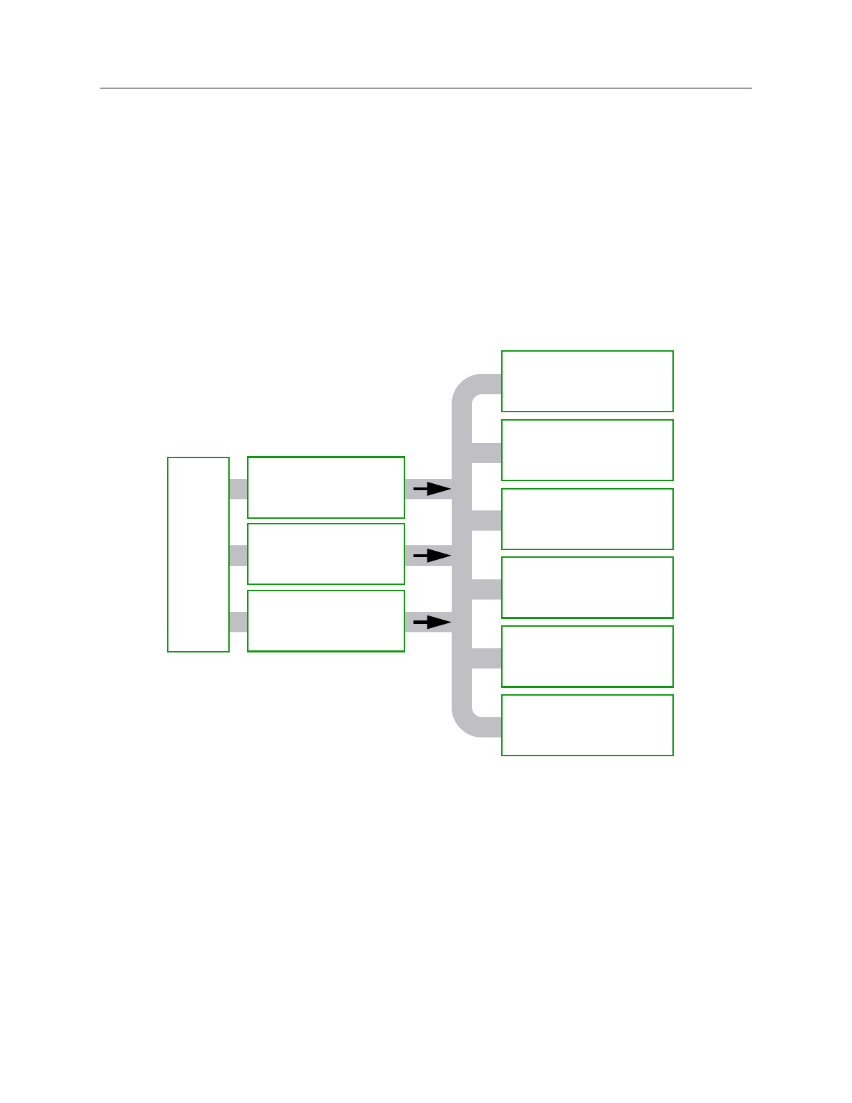
Figure 1 shows the Mentor Graphics DFT manuals and their relationship to each
other and is followed by a list of descriptions for these documents.
Figure 1. DFT Documentation Roadmap
Boundary Scan Process Guide — provides process, concept, and procedure
information for the boundary scan product, BSDArchitect. It also includes
information on how to integrate boundary scan with the other DFT
technologies.
BSDArchitect Reference Manual — provides reference information for
BSDArchitect, the boundary scan product.
DFTAdvisor
Reference Manual
FastScan & FlexTest
Reference Manual
Design-for-Test
Manual
Common Resources
Design-for-Test
Release Notes
LBISTArchitect
Reference Manual
MBISTArchitect
Reference Manual
Scan and ATPG
Process Guide
Built-in Self-Test
Process Guide
BSDArchitect
Reference Manual
Boundary Scan
Process Guide

FastScan and FlexTest Reference Manual, V8.6_4
xx
Related Publications About This Manual
Built-in Self-Test Process Guide — provides process, concept, and
procedure information for using MBISTArchitect, LBISTArchitect, and
other Mentor Graphics tools in the context of your BIST design process.
Design-for-Test Common Resources Manual — contains information
common to many of the DFT tools: design rule checks (DRC), DFTInsight
(the schematic viewer), library creation, VHDL support, Verilog support,
Spice support, and test procedure file format.
Design-for-Test Release Notes — provides release information that reflects
changes to the DFT products for the software version release.
DFTAdvisor Reference Manual — provides reference information for
DFTAdvisor (internal scan insertion) and DFTInsight (schematic viewer)
products.
FastScan and FlexTest Reference Manual — provides reference
information for FastScan (full-scan ATPG), FlexTest (non- to partial-scan
ATPG), and DFTInsight (schematic viewer) products.
LBISTArchitect Reference Manual — provides reference information for
LBISTArchitect, the logic built-in self-test product.
MBISTArchitect Reference Manual — provides reference information for
MBISTArchitect, the memory built-in self-test product.
Scan and ATPG Process Guide — provides process, concept, and
procedure information for using DFTAdvisor, FastScan, and FlexTest in
the context of your DFT design process.
Using Mentor Graphics Documentation with Acrobat Exchange —
describes how to set up and use the Mentor Graphics-supplied Acrobat
Exchange with enhancement plugins for online viewing of Mentor
Graphics PDF-based documentation and help. The manual contains
procedures for using Mentor Graphics documentation, including setting up
online manuals and help, opening documents, and using full-text searches.
Also included are tips on using Exchange.

About This Manual Acronyms Used in This Manual
FastScan and FlexTest Reference Manual, V8.6_4 xxi
Acronyms Used in This Manual
Below is an alphabetical listing of the acronyms used in this manual:
ASIC - Application Specific IC
ATE - Automatic Test Equipment
ATPG - Automatic Test Pattern Generation
AU - ATPG_Untestable fault
AVI - ASIC Vector Interfaces
BIST - Built-In Self Test
BSDA - Boundary Scan Design Architect
BSDL - Boundary Scan Design Language
CUT - Circuit Under Test
DFT - Design For Test
DFTA - DFTAdvisor
DFTI - DFTInsight
DRC - Design Rules Check
DUT - Device Under Test
EDDM - Electronic Design Data Model
EDIF - Electronic Design Interchange Format
FS - FastScan
FT - FlexTest

FastScan and FlexTest Reference Manual, V8.6_4
xxii
Acronyms Used in This Manual About This Manual
GENIE - General Interpreted Environment
IDDQ - Quiescent Drain Current
I/O - Input/Output
JTAG - Joint Test Action Group
LFSR - Linear Feedback Shift Register
LSSD - Level Sensitive Scan Design
MCM - Multi-Chip Module
MISR - Multiple Input Signature Register
PGS - Pulse Generator Sink
PI - Primary Input
PRPG - Pseudo-Random Pattern Generator
PO - Primary Output
PU - Posdet_Untestable fault
SFP - Single Fault Propagation
TDL - TEGAS Design Language
UI - User Interface
VHDL - VHSIC Hardware Description Language
VHSIC - Very High Speed IC
WDB - Waveform DataBase

About This Manual Command Line Syntax Conventions
FastScan and FlexTest Reference Manual, V8.6_4 xxiii
Command Line Syntax Conventions
Each point-tool manual will include the following notation conventions section in
the ATM chapter. For more information on Mentor Graphics documentation
conventions, see the “Mentor Graphics Learning Products Style Guide”
The notational elements for command line syntax are as follows:
Bold A bold font indicates a required argument.
[ ] Square brackets enclose optional arguments (in command line
syntax only). Do not enter the brackets.
UPPercase Required command letters are in uppercase; in most cases, you
may omit lowercase letters when entering commands or literal
arguments and you need not use uppercase. Command names and
options are normally case insensitive, but for some tools the initial
command name is case sensitive and must be lowercase.
Commands usually follow the 3-2-1 rule: the first three letters of
the first word, the first two letters of the second word, and the first
letter of the third, fourth, etc. words.
Italic An italic font indicates a user-supplied argument.
An underlined item indicates either the default argument or the
default value of an argument.
{ } Braces enclose arguments to show grouping. Do not enter the
braces.
| The vertical bar indicates an either/or choice between items. Do
not include the bar in the command.
… An ellipsis follows an argument that may appear more than once.
Do not include the ellipsis in commands.
You should enter literal text (that which is not in italics) exactly as shown.

FastScan and FlexTest Reference Manual, V8.6_4
xxiv
Command Line Syntax Conventions About This Manual

FastScan and FlexTest Reference Manual, V8.6_4 1-1
Chapter 1
Introduction
FastScan and FlexTest are Mentor Graphics high-performance Automatic Test
Pattern Generation (ATPG) tools. FastScan performs full-scan and scan-
sequential ATPG, while FlexTest performs sequential ATPG. These are two of
several tools in the Mentor Graphics Design-for-Test (DFT) tool suite. The
following subsections list the features and inputs/outputs of the tools. For
information on using FastScan or FlexTest in the context of a DFT flow, refer to
the “Generating Test Patterns” chapter in the Scan and ATPG Process Guide.
Features
FastScan and FlexTest share numerous features, including the following:
•You can use them within a Mentor Graphics flow or as a point tool within
other design flows.
•Contain an internal high-speed fault simulator.
•Read most standard gate-level netlists.
•Produce a number of standard test pattern data formats.
•Contain a powerful design rules checker.
FastScan-specific features include the following:
•Produces very high coverage test pattern sets for full-scan and scan-
sequential designs. Scan-sequential designs contain well-behaved
sequential scan circuitry, including non-scan latches, sequential memories,
and limited sequential depth.

FastScan and FlexTest Reference Manual, V8.6_4
1-2
Inputs and Outputs Introduction
•Contains functionality for handling embedded RAM and ROM.
•Contains functionality for simulating and generating test pattern sets for
BIST circuitry.
FlexTest-specific features include the following:
•Supports a wide range of DFT structures.
•Can display a wide variety of useful information—from design and
debugging information to statistical reports for the generated test set.
Inputs and Outputs
FastScan and FlexTest utilize the following inputs:
•Design - The supported netlist formats are EDDM, EDIF, GENIE, Verilog,
VHDL, SPICE and TDL.
•Test Procedure File - This file defines the operation of the scan circuitry in
your design. You can generate the file by hand or using the Write ATPG
Setup command in DFTAdvisor. For more information on test procedure
files, refer to “Test Procedure Files” in the Scan and ATPG Process Guide.
•Library - This file contains model descriptions for all library cells used in
your design.
•Fault List - This is an external fault list that you can use as a source of faults
for the internal fault list of FlexTest.
•Test Patterns - This is a set of externally-generated test patterns that you can
use as the pattern source for simulation.

Introduction Inputs and Outputs
FastScan and FlexTest Reference Manual, V8.6_4 1-3
FastScan and FlexTest produce the following outputs:
•Test Patterns - This file set contains test patterns in one or more of the
supported simulator or ASIC vendor pattern formats. For more information
on the available test pattern formats, refer to the Save Patterns command
reference page within this manual, or the “Saving the Patterns” section in
the Scan and ATPG Process Guide.
•ATPG Information Files - These files contain session information that you
can save using various FlexTest commands.
•Fault List - This is an ASCII file containing internal fault information in the
standard Mentor Graphics fault format.

FastScan and FlexTest Reference Manual, V8.6_4
1-4
Inputs and Outputs Introduction

FastScan and FlexTest Reference Manual, V8.6_4 2-1
Chapter 2
Command Dictionary
This chapter contains descriptions of the FastScan, FlexTest, and DFTInsight
commands. The subsections are named for the command they describe. For quick
reference, the commands appear alphabetically with each beginning on a separate
page.
Command Summary
Table 2-1 contains a summary of the commands described in this manual. The
three columns that separate the command name and the description indicate the
tools in which you can use the commands. The following tool acronyms are used
in the table:
DFTI DFTInsight FS FastScan FT FlexTest
Table 2-1. Command Summary
Command
D
F
T
IF
SF
TDescription
Abort Interrupted
Process •Aborts a command placed in suspended state
by a Control-C interrupt while the Set
Interrupt Handling command is on.
Add Ambiguous Paths •Specifies for FastScan to select multiple paths
when there is path ambiguity.
Add Atpg Constraints ••Specifies that the tool restrict all patterns it
places into the internal pattern set according
to the user-defined constraints.

FastScan and FlexTest Reference Manual, V8.6_4
2-2
Command Summary Command Dictionary
Add Atpg Functions ••Creates an ATPG function that you can then
use when generating user-defined ATPG
constraints.
Add Capture Handling •Specifies the data capturing behavior for the
given state element.
Add Cell Constraints ••Constrains scan cells to be at a constant value.
Add Cell Library ••Specifies the EDIF library in which to place
all or specified library models.
Add Clocks ••Adds clock primary inputs to the clock list.
Add Cone Blocks ••Specifies the blockage points that you want
the tool to use during the calculation of the
clock and effect cones.
Add Control Points •Adds control points to output pins.
Add Display Instances •••Adds the specified instances to the netlist for
display.
Add Display Loop •••Displays all the gates in a specified feedback
path.
Add Display Path •••Displays all the gates associated with the
specified path.
Add Display Scanpath •••Displays all the associated gates between two
positions in a scan chain.
Add Faults ••Adds faults into the current fault list.
Add Iddq Constraints ••Sets constraints for generation or selection of
IDDQ patterns.
Table 2-1. Command Summary [continued]
Command
D
F
T
IF
SF
TDescription

Command Dictionary Command Summary
FastScan and FlexTest Reference Manual, V8.6_4 2-3
Add Initial States •Specifies an initial state for the selected
sequential instance.
Add LFSR Connections •Connects an external pin to a Linear Feedback
Shift Register (LFSR).
Add LFSR Taps •Adds the tap configuration to a Linear
Feedback Shift Register (LFSR).
Add LFSRs •Adds Linear Feedback Shift Registers
(LFSRs) for use as Pseudo-Random Pattern
Generators (PRPGs) or Multiple Input
Signature Registers (MISRs).
Add Lists ••Adds pins to the list of pins on which to
report.
Add Mos Direction ••Assigns the direction of a bi-directional MOS
transistor.
Add Net Property ••Defines the net in the Spice design and library
as VDD or GND.
Add Nofaults ••Places nofault settings either on pin
pathnames, pin names of specified instances,
or modules.
Add Nonscan Handling •Overrides behavior classification of non-scan
elements that FlexTest learns during the
design rules checking process.
Add Notest Points •Adds circuit points to list for exclusion from
testability insertion.
Add Observe Points •Adds observe points to output pins.
Table 2-1. Command Summary [continued]
Command
D
F
T
IF
SF
TDescription

FastScan and FlexTest Reference Manual, V8.6_4
2-4
Command Summary Command Dictionary
Add Output Masks ••Ignores any fault effects that propagate to the
primary output pins you name.
Add Pin Constraints ••Adds pin constraints to primary inputs and
input channel to I/O pins.
Add Pin Equivalences ••Adds restrictions to primary inputs such that
they have equal or inverted values.
Add Pin Strobes •Adds strobe time to the primary outputs.
Add Primary Inputs ••Adds primary inputs.
Add Primary Outputs ••Adds primary outputs.
Add Random Weights •Specifies the random pattern weighting
factors for primary inputs.
Add Read Controls ••Adds an off-state value to read control lines.
Add Scan Chains ••Adds a scan chain to a scan group.
Add Scan Groups ••Adds a scan chain group to the system.
Add Scan Instances •Adds sequential instances to the scan instance
list.
Add Scan Models •Adds sequential models to the scan model list.
Add Slow Pad •Sets the specified I/O pin as a slow pad.
Add Tied Signals ••Adds a value to floating signals or pins.
Add Write Controls ••Adds an off-state value to specified write
control lines.
Table 2-1. Command Summary [continued]
Command
D
F
T
IF
SF
TDescription

Command Dictionary Command Summary
FastScan and FlexTest Reference Manual, V8.6_4 2-5
Analyze Atpg
Constraints ••Specifies for FastScan or FlexTest to check
the ATPG constraints you’ve created for their
satisfiability or for their mutual exclusivity.
Analyze Bus ••Causes the tool to analyze the specified bus
gates for contention problems.
Analyze Control •Calculates zero and one-state controllability.
Analyze Control
Signals ••Identifies the primary inputs of control
signals.
Analyze Drc Violation •••Generates a netlist of the portion of the design
involved with the specified rule violation
number.
Analyze Fault ••Performs an analysis to identify why a fault is
not detected and optionally displays the
relevant circuitry in DFTInsight.
Analyze Observe •Calculates observability coverage.
Analyze Race •Checks for race conditions between the clock
and data signals.
Analyze Restrictions •Performs an analysis to automatically
determine the source of the problems from a
failed ATPG run.
Close Schematic
Viewer •••Terminates the optional schematic viewing
application (DFTInsight).
Compress Patterns ••Compresses patterns in the current test pattern
set.
Create Initialization
Patterns •Creates RAM initialization patterns and
places them in the internal pattern set.
Table 2-1. Command Summary [continued]
Command
D
F
T
IF
SF
TDescription

FastScan and FlexTest Reference Manual, V8.6_4
2-6
Command Summary Command Dictionary
Create Patterns •Automates good ATPG compression flow.
Delete Atpg Constraints ••Removes the state restrictions from the
specified objects.
Delete Atpg Functions ••Removes the specified function definitions.
Delete Capture
Handling •Removes the special data capture handling for
the specified objects.
Delete Cell Constraints ••Removes constraints placed on scan cells.
Delete Clocks ••Removes primary input pins from the clock
list.
Delete Cone Blocks ••Removes the specified output pin names from
the user-created list which the tool uses to
calculate the clock and effect cones.
Delete Control Points •Removes previously specified control points.
Delete Display
Instances •••Removes the specified objects from the
display in DFTInsight.
Delete Faults ••Removes faults from the current fault list.
Delete Iddq Constraints ••Removes the IDDQ restrictions from the
specified pins.
Delete Initial States •Removes the initial state settings for the
specified instance names.
Delete LFSR
Connections •Removes connections between the specified
primary pins and Linear Feedback Shift
Registers (LFSRs).
Delete LFSR Taps •Removes the tap positions from a Linear
Feedback Shift Register (LFSR).
Table 2-1. Command Summary [continued]
Command
D
F
T
IF
SF
TDescription

Command Dictionary Command Summary
FastScan and FlexTest Reference Manual, V8.6_4 2-7
Delete LFSRs •Removes the specified Linear Feedback Shift
Registers (LFSRs).
Delete Lists ••Removes the specified pins from the pin list
that the tool monitors while in the Fault or
Good simulation system mode.
Delete Mos Direction ••Resets the VDD or GND net in the Spice
design and library.
Delete Net Property ••Resets the VDD or GND net in the Spice
design and library.
Delete Nofaults ••Removes the nofault settings from either the
specified pin or instance/module pathnames.
Delete Nonscan
Handling •Removes the overriding learned behavior
classification for the specified non-scan
elements.
Delete Notest Points •Removes the circuit points which the tool
cannot use for testability insertion from the
specified pins.
Delete Observe Points •Removes observe points from the specified
pins.
Delete Output Masks ••Removes the masking of the specified
primary output pins.
Delete Paths •Removes the specified path delay faults from
the current fault list.
Delete Pin Constraints ••Removes the pin constraints from the
specified primary input pins.
Table 2-1. Command Summary [continued]
Command
D
F
T
IF
SF
TDescription

FastScan and FlexTest Reference Manual, V8.6_4
2-8
Command Summary Command Dictionary
Delete Pin
Equivalences ••Removes the pin equivalence specifications
for the designated primary input pins.
Delete Pin Strobes •Removes the strobe time from the specified
primary output pins.
Delete Primary Inputs ••Removes the specified primary inputs from
the current netlist.
Delete Primary Outputs ••Removes the specified primary outputs from
the current netlist.
Delete Random
Weights •Removes the random pattern weighting
factors for the specified primary input pins.
Delete Read Controls ••Removes the read control line definitions
from the specified primary input pins.
Delete Scan Chains ••Removes the specified scan chain definitions
from the scan chain list.
Delete Scan Groups ••Removes the specified scan chain group
definitions from the scan chain group list.
Delete Scan Instances •Removes from the scan instance list the
specified sequential instances.
Delete Scan Models •Removes the specified sequential models
from the scan model list.
Delete Slow Pad •Resets the specified I/O pin back to the
default simulation mode.
Delete Tied Signals ••Removes the assigned (tied) value from the
specified floating nets or pins.
Delete Write Controls ••Removes the write control line definitions
from the specified primary input pins.
Table 2-1. Command Summary [continued]
Command
D
F
T
IF
SF
TDescription

Command Dictionary Command Summary
FastScan and FlexTest Reference Manual, V8.6_4 2-9
Diagnose Failures •Diagnoses the failing patterns that the
specified file identifies.
Dofile ••Executes the commands contained within the
specified file.
Exit ••Terminates the application tool program.
Extract Subckts ••Performs matching and conversion between
the bi-directional MOS instance and the
ATPG library model.
Flatten Model ••Creates a primitive gate simulation
representation of the design.
Flatten Subckt ••Flattens the SUBCKT in the Spice design.
Help ••Displays the usage syntax and system mode
for the specified command.
Insert Testability •Performs testability analysis to achieve
maximum test coverage.
Load Faults ••Updates the current fault population to
include or exclude the faults contained in the
specified fault file.
Load Paths •Reads into FastScan the path definitions
contained in the specified ASCII file.
Macrotest •Automates the testing of embedded RAMs or
ROMs, embedded hierarchical instances, and
embedded blocks of logic with unidirectional
I/O.
Mark •••Highlights the objects that you specify in the
Schematic View window.
Table 2-1. Command Summary [continued]
Command
D
F
T
IF
SF
TDescription

FastScan and FlexTest Reference Manual, V8.6_4
2-10
Command Summary Command Dictionary
Open Schematic
Viewer ••Invokes the optional schematic viewing
application, DFTInsight.
Read Modelfile ••Initializes the specified RAM or ROM gate
using the memory states contained in the
named modelfile.
Read Procfile ••Reads the specified new enhanced procedure
file.
Read Subckts Library ••Reads the specified Spice SUBCKT library.
Redo Display •••Nullifies the schematic view effects of an
Undo command.
Report Aborted Faults ••Displays information on undetected faults
caused when the tool aborted the simulation
during the ATPG process.
Report Atpg
Constraints ••Displays all the current ATPG state
restrictions and the pins on which they reside.
Report Atpg Functions ••Displays all the current ATPG function
definitions.
Report AU Faults •Displays information on ATPG untestable
faults.
Report Bus Data ••Displays the bus data information for either an
individual bus gate or for the buses of a
specific type.
Report Capture
Handling •Displays any special data capture handling
currently in use.
Report Cell Constraints ••Displays a list of all the constrained scan
cells.
Table 2-1. Command Summary [continued]
Command
D
F
T
IF
SF
TDescription

Command Dictionary Command Summary
FastScan and FlexTest Reference Manual, V8.6_4 2-11
Report Clocks ••Displays a list of all the primary input pins
currently in the clock list.
Report Cone Blocks ••Displays the current user-defined output pin
pathnames that the tool uses to calculate the
clock and effect cones.
Report Control Data •Displays information from the last Analyze
Control command.
Report Control Points •Displays the list of control points.
Report Core Memory •Displays the amount of memory FlexTest
requires to avoid paging during the ATPG and
simulation processes.
Report Display
Instances •••Displays a textual report of the netlist
information for either the specified gates or
instances or for all the gates in the current
schematic view display.
Report Drc Rules ••Displays either a summary of all the Design
Rule Check (DRC) violations or the data for a
specific violation.
Report Environment ••Displays the current values of all the “set”
commands.
Report Failures •Displays the failing pattern results.
Report Faults ••Displays fault information from the current
fault list.
Report Feedback Paths •••Displays a textual report of the currently
identified feedback paths.
Table 2-1. Command Summary [continued]
Command
D
F
T
IF
SF
TDescription

FastScan and FlexTest Reference Manual, V8.6_4
2-12
Command Summary Command Dictionary
Report Flatten Rules •••Displays either a summary of all the flattening
rule violations or the data for a specific
violation.
Report Gates ••Displays the netlist information for the
specified gates.
Report Hosts •Displays information on the hosts available
for distributed processing.
Report Id Stamp •Displays the unique identifier that FastScan
assigns each internal pattern set.
Report Iddq Constraints ••Displays the current IDDQ constraints for the
specified pins.
Report Initial States •Displays the initial state settings of the
specified design instances.
Report LFSR
Connections •Displays a list of all the connections between
Linear Feedback Shift Registers (LFSRs) and
primary pins.
Report LFSRs •Displays a list of definitions for all the current
Linear Feedback Shift Registers (LFSRs).
Report Lists ••Displays a list of pins which the tool reports
on while in the Fault or Good simulation
system mode.
Report Loops ••Displays a list of all the current loops.
Report Mos Direction ••Reports the direction MOS instances in the
Spice design and Spice SUBCKT library.
Report Net Properties ••Reports the VDD or GND net properties in
the Spice design and library.
Table 2-1. Command Summary [continued]
Command
D
F
T
IF
SF
TDescription

Command Dictionary Command Summary
FastScan and FlexTest Reference Manual, V8.6_4 2-13
Report Nofaults ••Displays the nofault settings for the specified
pin pathnames or pin names of instances.
Report Nonscan Cells ••Displays the non-scan cells whose model type
you specify.
Report Nonscan
Handling •Displays the overriding learned behavior
classification for the specified non-scan
elements.
Report Notest Points •Displays all the circuit points for which you
do not want FastScan to insert controllability
and observability.
Report Observe Data •Displays information from the preceding
Analyze Observe command.
Report Observe Points •Displays a list of all the current observe
points.
Report Output Masks ••Displays a list of the currently masked
primary output pins.
Report Paths •Displays the path definitions of the specified
loaded paths.
Report Pin Constraints ••Displays the pin constraints of the primary
inputs.
Report Pin
Equivalences ••Displays the pin equivalences of the primary
inputs.
Report Pin Strobes •Displays the current pin strobe timing for the
specified primary output pins.
Report Primary Inputs ••Displays the specified primary inputs.
Table 2-1. Command Summary [continued]
Command
D
F
T
IF
SF
TDescription

FastScan and FlexTest Reference Manual, V8.6_4
2-14
Command Summary Command Dictionary
Report Primary Outputs ••Displays the specified primary outputs.
Report Procedure ••Displays the specified procedure.
Report Pulse
Generators ••Displays the list of pulse generator sink (PGS)
gates.
Report Random
Weights •Displays the current random pattern
weighting factors for all primary inputs in the
random weight list.
Report Read Controls ••Displays all of the currently defined read
control lines.
Report Scan Cells ••Displays a report on the scan cells that reside
in the specified scan chains.
Report Scan Chains ••Displays a report on all the current scan
chains.
Report Scan Groups ••Displays a report on all the current scan chain
groups.
Report Scan Instances •Displays the currently defined sequential scan
instances.
Report Scan Models •Displays the sequential scan models currently
in the scan model list.
Report Seq_transparent
Procedures •Displays a list of seq_transparent test
procedures along with the associated data that
you specify.
Report Slow Pads •Displays all I/O pins marked as slow.
Report Statistics ••Displays a detailed report of the design’s
simulation statistics.
Table 2-1. Command Summary [continued]
Command
D
F
T
IF
SF
TDescription

Command Dictionary Command Summary
FastScan and FlexTest Reference Manual, V8.6_4 2-15
Report Test Stimulus •Displays the stimulus necessary to satisfy the
specified set, write, or read conditions.
Report Testability Data ••Analyzes collapsed faults for the specified
fault class and displays the analysis.
Report Tied Signals ••Displays a list of the tied floating signals and
pins.
Report Timeplate ••Displays the specified timeplate.
Report Version Data •Displays the current software version
information.
Report Write Controls ••Displays the currently defined write control
lines and their off-states.
Reset Au Faults ••Re-classifies the faults in certain untestable
categories.
Reset State ••Resets the circuit status.
Resume Interrupted
Process •Continues a command that you placed in a
suspended state by entering a Control-C
interrupt.
Run ••Runs a simulation or ATPG process.
Save Flattened Model •Saves the flattened circuit model, the scan
trace, and all DRC related information to a
specific file.
Save Patterns ••Saves the current test pattern set to a file in
the format that you specify.
Save Schematic ••Saves the schematic currently displayed by
DFTInsight.
Table 2-1. Command Summary [continued]
Command
D
F
T
IF
SF
TDescription

FastScan and FlexTest Reference Manual, V8.6_4
2-16
Command Summary Command Dictionary
Select Iddq Patterns ••Selects the patterns that most effectively
detect IDDQ faults.
Select Object •••Selects the specified objects in the design.
Set Abort Limit ••Specifies the abort limit for the test pattern
generator.
Set Atpg Compression •Specifies for the ATPG to perform dynamic
pattern compression.
Set Atpg Limits ••Specifies the ATPG process limits at which
the tool terminates the ATPG process.
Set Atpg Window •Allows you to specify the size of the FlexTest
simulation window.
Set AU Analysis •Specifies whether the ATPG uses the ATPG
untestable information to place ATPG
untestable faults directly in the AU fault class.
Set Bist Initialization •Specifies the scan chain input value which
indicates the states of the scan cells before
FastScan applies Built-In Self Test (BIST)
patterns.
Set Bus Handling ••Specifies the bus contention results that you
desire for the identified buses.
Set Bus Simulation •Specifies whether the tool uses global or local
bus simulation analysis.
Set Capture Clock ••Specifies the capture clock name for random
pattern simulation.
Table 2-1. Command Summary [continued]
Command
D
F
T
IF
SF
TDescription

Command Dictionary Command Summary
FastScan and FlexTest Reference Manual, V8.6_4 2-17
Set Capture Handling •Specifies how FastScan globally handles the
data capture of state elements that have C3
and C4 rule violations.
Set Capture Limit •Specifies the number of test cycles between
two consecutive scan operations.
Set Checkpoint ••Specifies whether the tool uses the checkpoint
functionality.
Set Clock Restriction ••Specifies whether the ATPG can create
patterns with more than one active capture
clock.
Set Clock_off
Simulation •Enables or disables simulation with the clocks
off.
Set Clockpo Patterns •Specifies whether ATPG can perform pattern
creation for primary outputs that connect to
clocks.
Set Contention Check ••Specifies the conditions of contention
checking.
Set Control Threshold •Specifies the controllability value for random
pattern simulation.
Set Decision Order •Specifies how the ATPG determines and uses
observation points.
Set Dofile Abort ••Lets you specify whether the tool aborts or
continues dofile execution if an error
condition is detected.
Set Drc Handling ••Specifies how the tool globally handles design
rule violations.
Table 2-1. Command Summary [continued]
Command
D
F
T
IF
SF
TDescription

FastScan and FlexTest Reference Manual, V8.6_4
2-18
Command Summary Command Dictionary
Set Driver Restriction ••Specifies whether the tool allows multiple
drivers on buses and multiple active ports on
gates.
Set Fails Report ••Specifies whether the design rules checker
displays clock rule failures.
Set Fault Mode ••Specifies whether the fault mode is collapsed
or uncollapsed.
Set Fault Sampling •Specifies the fault sampling percentage.
Set Fault Type ••Specifies the fault model for which the tool
develops or selects ATPG patterns.
Set Flatten Handling •••Specifies how the tool globally handles
flattening violations.
Set Gate Level •••Specifies the hierarchical level of gate
reporting and displaying.
Set Gate Report ••Specifies the additional display information
for the Report Gates command.
Set Hypertrophic Limit •Specifies the percentage of the original
design’s sequential primitives that can differ
from the good machine before the tool
classifies them as hypertrophic faults.
Set Iddq Checks ••Specifies the restrictions and conditions that
you want the tool to use when creating or
selecting patterns for detecting IDDQ faults.
Set Iddq Strobe ••Specifies on which patterns (cycles) the tool
will simulate IDDQ measurements.
Table 2-1. Command Summary [continued]
Command
D
F
T
IF
SF
TDescription

Command Dictionary Command Summary
FastScan and FlexTest Reference Manual, V8.6_4 2-19
Set Instancename
Visibility •••Specifies whether DFTInsight displays
instance names immediately above each
instance in the Schematic View area.
Set Instruction Atpg •Specifies whether FlexTest generates
instruction-based test vectors using the
random ATPG process.
Set Internal Fault ••Specifies whether the tool allows faults within
or only on the boundary of library models.
Set Internal Name ••Specifies whether to delete or keep pin names
of library internal pins containing no-fault
attributes.
Set Interrupt Handling •Specifies how FlexTest interprets a Control-C
interrupt.
Set IO Mask •Modifies the behavior of IO pins so that their
expected values will always be X during test
cycles in which the primary input portion of
the IO pin is being forced.
Set Learn Report ••Specifies whether the Report Gates command
can display the learned behavior for a specific
gate.
Set List File ••Specifies the name of the list file into which
the tool places the pins’ logic values during
simulation.
Set Logfile Handling ••Specifies for the tool to direct the transcript
information to a file.
Set Loop Handling ••Specifies how the tool handles feedback
networks.
Table 2-1. Command Summary [continued]
Command
D
F
T
IF
SF
TDescription

FastScan and FlexTest Reference Manual, V8.6_4
2-20
Command Summary Command Dictionary
Set Multiple Load •Specifies how the tool handles multiple scan
loads.
Set Net Dominance ••Specifies the fault effect of bus contention on
tri-state nets.
Set Net Resolution ••Specifies the behavior of multi-driver nets.
Set Nonscan Model •Specifies how FlexTest classifies the behavior
of non-scan cells with the HOLD and INITX
functionality during the operation of the scan
chain.
Set Number Shifts •Sets the number of shifts for loading or
unloading the scan chains.
Set Observation Point •Specifies the observation point for random
pattern fault simulation.
Set Observe Threshold •Specifies the minimum number of
observations necessary for the Analyze
Observe command to consider a point
adequately observed.
Set Output Comparison •Specifies whether FlexTest performs a good
circuit simulation comparison.
Set Output Mask •Specifies how FlexTest handles an unknown
(X) state in an external pattern set.
Set Pathdelay Holdpi •Specifies whether the ATPG keeps non-clock
primary inputs at a constant state after the first
force.
Set Pattern Source ••Specifies the source of the patterns for future
Run commands.
Table 2-1. Command Summary [continued]
Command
D
F
T
IF
SF
TDescription

Command Dictionary Command Summary
FastScan and FlexTest Reference Manual, V8.6_4 2-21
Set Possible Credit ••Specifies the percentage of credit that the tool
assigns possible-detected faults.
Set Procedure
Cycle_checking ••Enables test procedure cycle timing checking
to be done immediately following scan chain
tracing during design rules checking.
Set Pulse Generators ••Specifies whether the tool identifies pulse
generator sink (PGS) gates.
Set Race Data •Specifies how FlexTest handles the output
states of a flip-flop when the data input pin
changes at the same time as the clock triggers.
Set Rail Strength •Specifies FlexTest to set the strongest strength
of a fault site to a bus driver.
Set Ram Initialization •Specifies whether to initialize RAM and
ROM gates that do not have initialization
files.
Set Ram Test •Specifies the mode for RAM testing with
random or Built-In Self Test (BIST) patterns.
Set Random Atpg ••Specifies whether the tool uses random
patterns during ATPG.
Set Random Clocks •Specifies whether FastScan uses
combinational or clock_sequential patterns
for random pattern simulation.
Set Random Patterns •Specifies the number of random patterns
FastScan simulates.
Set Random Weights •Specifies the default random pattern
weighting factor for primary inputs.
Table 2-1. Command Summary [continued]
Command
D
F
T
IF
SF
TDescription

FastScan and FlexTest Reference Manual, V8.6_4
2-22
Command Summary Command Dictionary
Set Redundancy
Identification •Specifies whether FlexTest performs the
checks for redundant logic when leaving the
Setup mode.
Set Schematic Display •••Changes the default schematic display
environment settings for DFTInsight.
Set Screen Display ••Specifies whether the tool writes the transcript
to the session window.
Set Self Initialization •Specifies whether FlexTest turns on/off self-
initializing sequence behavior.
Set Sensitization
Checking ••Specifies whether DRC checking attempts to
verify a suspected C3 or C4 rules violation.
Set Sequential Learning ••Specifies whether the tool performs the
learning analysis of sequential elements to
make the ATPG process more efficient.
Set Shadow Check •Specifies whether FastScan will identify
sequential elements as a “shadow” element
during scan chain tracing.
Set Simulation Mode •Specifies whether the ATPG simulation run
uses combinational or sequential RAM test
patterns.
Set Skewed Load •Specifies whether FastScan includes a skewed
load in the patterns.
Set Split Capture_cycle •Enables or disables the simulation of level
sensitive and leading edge state elements
updating as a result of applied clocks.
Table 2-1. Command Summary [continued]
Command
D
F
T
IF
SF
TDescription

Command Dictionary Command Summary
FastScan and FlexTest Reference Manual, V8.6_4 2-23
Set Stability Check •Specifies whether the tool checks the effect of
applying the main shift procedure on non-scan
cells.
Set Static Learning ••Specifies whether FastScan or FlexTest
performs the learning analysis to make the
ATPG process more efficient.
Set Stg Extraction •Specifies whether FlexTest performs state
transition graph extraction.
Set System Mode ••Specifies the system mode you want the tool
to enter.
Set Test Cycle •Specifies the number of timeframes per test
cycle.
Set Trace Report ••Specifies whether the tool displays gates in
the scan chain trace.
Set Transition Holdpi •Specifies for FastScan to freeze all primary
input values other than clocks and RAM
controls during multiple cycles of pattern
generation.
Set Unused Net •Specifies whether FlexTest removes unused
bus and wire nets in the design..
Set Workspace Size •Increases the workspace so that FastScan can
try to detect the undetected faults that were
aborted due to workspace constraints.
Set Xclock Handling •Specifies whether FastScan changes the
sequential element model to always set the
output of the element to be X when any of its
clock inputs become X.
Table 2-1. Command Summary [continued]
Command
D
F
T
IF
SF
TDescription

FastScan and FlexTest Reference Manual, V8.6_4
2-24
Command Summary Command Dictionary
Set Z Handling ••Specifies how the tool handles high
impedance signals for internal and external
tri-state nets.
Set Zhold Behavior •Specifies whether ZHOLD gates retain their
state values.
Set Zoom Factor •••Specifies the scale factor that the zoom icons
use in the DFTInsight Schematic View
window.
Setup Checkpoint ••Specifies the checkpoint file to which the tool
writes test patterns or fault lists during ATPG.
Setup LFSRs •Changes the shift_type and tap_type default
setting for the Add LFSRs and Add LFSR
Taps commands.
Setup Pin Constraints ••Changes the default cycle behavior for non-
constrained primary inputs.
Setup Pin Strobes •Changes the default strobe time for primary
outputs without specified strobe times.
Setup Tied Signals ••Changes the default value for floating pins
and floating nets which do not have assigned
values.
Step •Single-steps through several cycles of a test
set.
System ••Passes the specified command to the
operating system for execution.
Undo Display •••Restores the previous schematic view.
Table 2-1. Command Summary [continued]
Command
D
F
T
IF
SF
TDescription

Command Dictionary Command Summary
FastScan and FlexTest Reference Manual, V8.6_4 2-25
Unmark •••Removes the highlighting from the specified
object in Schematic View window.
Unselect Object •••Removes the specified objects from the
selection list.
Update Implication
Detections ••Performs an analysis on the undetected and
possibly-detected faults to see if the tool can
classify any of those faults as detected-by-
implication.
View •••Displays, in the DFTInsight Schematic View
window, the specified objects in the display
list.
View Area •••Displays an area that you specify in the
DFTInsight Schematic View window.
Write Core Memory •Writes to a file the amount of memory that
FlexTest requires to avoid paging during the
ATPG and simulation processes.
Write Environment •Writes the current environment settings to the
file that you specify.
Write Failures •Writes failing pattern results to a file.
Write Faults ••Writes fault information from the current fault
list to a file.
Write Initial States •Writes the initial state settings of design
instances into the file that you specify.
Write
Library_verification
Setup
•Generates ATPG library verification setup
files.
Table 2-1. Command Summary [continued]
Command
D
F
T
IF
SF
TDescription

FastScan and FlexTest Reference Manual, V8.6_4
2-26
Command Summary Command Dictionary
Write Loops ••Writes a list of all the current loops to a file.
Write Modelfile ••Writes all internal states for a RAM or ROM
gate into the file that you specify.
Write Netlist ••Writes the modified or new format netlist to
the specified file.
Write Paths •Writes the path definitions of the loaded paths
into the file that you specify.
Write Primary Inputs •Writes the primary inputs to the specified file.
Write Primary Outputs •Writes the primary outputs to the specified
file.
Write Procfile ••Writes existing procedure and timing data to
the named enhanced procedure file.
Write Statistics •Writes the current simulation statistics to the
specified file.
Write Timeplate •Writes the default timing information for non-
scan related events into the file that you
specify.
Zoom In •••Enlarges the objects in the DFTInsight
Schematic View window by reducing the
displayed area.
Zoom Out •••Reduces the objects in the DFTInsight
Schematic View window by enlarging the
displayed area.
Table 2-1. Command Summary [continued]
Command
D
F
T
IF
SF
TDescription

Command Dictionary Command Descriptions
FastScan and FlexTest Reference Manual, V8.6_4 2-27
Command Descriptions
The remaining pages in this chapter describe, in alphabetical order, the commands
used either in FastScan or FlexTest. Each command description begins on a new
page and contains a line indicating the applications that are supported. The
descriptions of commands that support both FastScan and FlexTest apply equally
to both tools unless specified otherwise. All commands are available in both the
point tool version and falcon version unless otherwise noted. You can use the line
continuation character “\” when application commands extend beyond the end of
a line. The line continuation character improves the readability of dofiles and
helps with the command line entry of multiple-argument commands.

FastScan and FlexTest Reference Manual, V8.6_4
2-28
Abort Interrupted Process Command Dictionary
Abort Interrupted Process
Tools Supported: FlexTest
Scope: All modes
Prerequisites: The Set Interrupt Handling command must be on and you must
interrupt a FlexTest command with a Control-C.
Usage
ABOrt INterrupted Process
Description
Aborts a command placed in suspended state by a Control-C interrupt while the
Set Interrupt Handling command is on.
The Abort Interrupted Process command aborts a FlexTest command that you
previously interrupted by pressing the Control-C keys. This removes the
interrupted command from the suspend-state and returns control to FlexTest.
Examples
The following example enables the suspend-state interrupt handling, begins an
ATPG run, and (sometime before the run completes) interrupts the run:
set interupt handling on
set system mode atpg
add faults -all
run
<Control-C>
Now with the Run suspended, the example continues by reporting all the
untestable faults to the display and then aborts the Run:
report faults faultlist -class ut
abort interrupted process
Related Commands
Resume Interrupted Process Set Interrupt Handling

Command Dictionary Add Ambiguous Paths
FastScan and FlexTest Reference Manual, V8.6_4 2-29
Add Ambiguous Paths
Tools Supported: FastScan
Scope: Atpg, Fault, and Good modes
Prerequisites: This command supports the path delay fault model.
Usage
ADD AMbiguous Paths {path_name | -All} [-Max_paths number]
Description
Specifies for FastScan to select multiple paths when there is path ambiguity.
When paths have path ambiguity, by default FastScan selects a single path that
satisfies the pin connectivity within the path definition file. If you want FastScan
to have additional choices for path ambiguity, you can use the Add Ambiguous
Paths command. When FastScan selects from the ambiguous paths it only
considers the possible connectivity between points and does not attempt to
determine whether the edges are sensitive.
For more information on path delay faults, refer to “Creating a Path Delay Test
Set” in the Scan and ATPG Process Guide.
Arguments
•path_name
A string that specifies the name of an ambiguous path that you want to add to
the path list.
•-All
A switch specifying that you want to add all ambiguous paths into the path list.
•-Max_paths number
An optional switch and integer pair that specifies the maximum number of
ambiguous paths you want FastScan to process. If you issue this command
without this switch, the default maximum number of ambiguous paths is 10.


Command Dictionary Add Atpg Constraints
FastScan and FlexTest Reference Manual, V8.6_4 2-31
Add Atpg Constraints
Tools Supported: FastScan and FlexTest
Scope: All modes
Prerequisites: You can use this command only after the tool flattens the design to
the simulation model, which happens when you first attempt to exit Setup
mode or when you issue the Flatten Model command.
Usage
For FastScan
ADD ATpg Constraints {0 | 1 | Z} {pin_pathname | gate_id# | function_name |
{-Cell cell_name {pin_name...}}}... [-Dynamic | -Static]
[-NOCapclock_check]
For FlexTest
ADD ATpg Constraints {0 | 1 | Z} {pin_pathname | net_pathname | gate_id# |
function_name | {-Cell cell_name {{pin_name | net_name}...}}}...
[-Dynamic | -Static]
Description
Specifies that the tool restrict all patterns it places into the internal pattern set
according to the user-defined constraints.
When the tool rejects a simulated pattern, it generates a message indicating the
number of rejected patterns and the first gate at which the failure occurred. You
can control the severity of the violation with the Set Contention Check command.
If you set the checking severity to Error, the tool terminates the simulation if it
rejects a pattern due to a user-defined constraint. You can analyze the simulation
data up to the termination point by using the Report Gates command with the
Error_pattern option.
When either FlexTest generates test patterns or FastScan generates test patterns
using deterministic test generation methods, the tool ensures that it uses the user-
defined pin constraints. When FastScan generates test patterns randomly, it does
not have complete control over the highly automated process, which means that
FastScan cannot ensure the use of the user-defined ATPG constraints. However,
FastScan will reject non-conforming random patterns.

FastScan and FlexTest Reference Manual, V8.6_4
2-32
Add Atpg Constraints Command Dictionary
If you change an ATPG constraint for a single internal set of patterns, the tool
continues pattern compression using the new constraints, which can cause the tool
to reject good patterns. Therefore, you should remove all ATPG constraints before
compressing the pattern set.
The Add Atpg Constraints command allows you to change the ATPG constraints
any time during the ATPG process (-Dynamic), affecting only the fault simulation
and test generation that occurs after the constraint changes. The fault simulator
rejects any subsequently simulated patterns that fail to meet the now current
constraints.
Dynamic ATPG constraints do not affect DRC because of their temporary nature.
Static ATPG constraints are unchangeable in ATPG mode, ensuring that DRC
must be repeated if they are changed.
FlexTest Specifics
In addition to the functionality mentioned above, the Add Atpg Constraints
command lets you constrain a net. Thus, if the circuit structure changes and the
ATPG constraints specified on the net pathnames do not change, you do not have
to identify the instance and the pin on which the ATPG constraints have to be
applied. If any ATPG constraint is added to the net, the equivalent pin is found
first and the function is added to that pin instead. Therefore, the Report Atpg
Constraints command may not show the net pathname specified. The constraints
added to the net can be deleted using the same net name.
Arguments
You must choose one of the following three literals to indicate the state value to
which you want the tool to constrain the specified object:
Note
If you constrain a pin by directly creating an ATPG constraint to
the pin_pathname, and then create another constraint that
indirectly creates a different constraint, the tool uses the constraint
that directly specified the pin_pathname (overriding the global
ATPG cell constraint).

Command Dictionary Add Atpg Constraints
FastScan and FlexTest Reference Manual, V8.6_4 2-33
•0 | 1 | Z
A literal that restricts the named object to a low state, high state, or high
impedance state, respectively.
The following lists the four methods for naming the objects on which you wish to
place the constraint. You can use any number of the four argument choices, in any
order.
•pin_pathname
A repeatable string that specifies the pathname to the pin on which you are
placing the constraint.
•net_pathname (FlexTest Only)
A repeatable string that specifies the pathname of the net on which you are
placing the constraint. You cannot put ATPG constraints on a net in any library
modules.
•gate_id#
A repeatable integer that specifies the gate identification number of the gate
you wish to constrain.
•function_name
A repeatable string that specifies the name of a function you created with the
Add Atpg Functions command. If you place a constraint on an ATPG function
(that you generated with the Add Atpg Function -Cell command), then the tool
also constrains all cells affected by that ATPG function. You can delete all
these constraints using the function_name argument with the Delete Atpg
Constraints command.
•-Cell cell_name {pin_name | net_name (FlexTest Only)}
A repeatable switch with a corresponding string pair that specifies the name of
a DFT library cell and the name of a specific net (FlexTest Only) or pin on that
cell. You can repeat the pin_name or net_name argument if there are multiple
pins or nets on a cell that you need to constrain.
If you use the -Cell option, the tool places an ATPG constraint on every
occurrence of that cell within the design. However, there is no -Cell option to
the Delete Atpg Constraints command, so you can either delete them
individually or delete all the ATPG constraints.

FastScan and FlexTest Reference Manual, V8.6_4
2-34
Add Atpg Constraints Command Dictionary
•-Dynamic
An optional switch specifying that the tool only need satisfy the ATPG
constraints during the ATPG process and not during design rules checking.
You can change these constraints during the ATPG process, therefore, Design
Rules Checking (DRC) does not check these constraints. This is the default
behavior.
•-Static
An optional switch specifying that the tool (during all its processes) must
always satisfy the ATPG constraint you are defining. You can only add or
delete static ATPG constraints when you are in Setup mode, ensuring that the
tool uses the static ATPG constraints for all ATPG analyses during design
rules checking. DRC checks for any violations of ATPG constraints during the
simulation of the test procedures (rule E12).
•-NOCapclock_check (FastScan Only)
An optional switch specifying that the tool suppress checking of specified
ATPG constraints after the capture clock. By default, the tool checks ATPG
constraints at the same time as bus contention. If, and only if, the tool performs
contention checking after the capture clock, the tool also checks ATPG
constraints after the capture clock.
In some situations, you may have some ATPG constraints that do not need to
be checked after the capture clock, although you may want the tool to check
other constraints and bus contention after the capture clock. In this case, you
can use the -Nocapclock_check switch on certain constraints to suppress
checking of those constraints after the capture clock.
Examples
The following example creates a user-defined ATPG function and then uses it
when creating ATPG pin constraints:
add atpg functions and_b_in and /i$144/q /i$141/q /i$142/q
add atpg constraints 0 /i$135/q
add atpg constraints 1 and_b_in


FastScan and FlexTest Reference Manual, V8.6_4
2-36
Add Atpg Functions Command Dictionary
Add Atpg Functions
Tools Supported: FastScan and FlexTest
Scope: All modes (except for some FlexTest options)
Prerequisites: You can use this command only after the tool flattens the design to
the simulation model, which happens when you first attempt to exit Setup
mode or when you issue the Flatten Model command.
Usage
For FastScan
ADD ATpg Functions function_name type {pin_pathname |gate_id# |
function_name | {-Cell cell_name {pin_name...}}}...
For FlexTest
ADD ATpg Functions function_name type {pin_pathname |net_pathname |
gate_id# | function_name | {-Cell cell_name {{pin_name | net_name}...}}}...
[-Init_state {0 | 1 | X}...]
Description
Creates an ATPG function that you can then use when generating user-defined
ATPG constraints.
You can specify any combination of pin pathnames, gate identification numbers,
and previously user-defined functions up to a maximum of 32 objects for each
function. You can precede any object with the ~ (tilde) character to indicate an
inverted input with respect to the function. If you specify an input pin pathname,
the tool automatically converts it to the output pin of the gate which drives that
input pin.
FlexTest Specifics
Temporal ATPG functions can be specified by using a Delay primitive to delay
the signal for one time frame. Temporal constraints can be achieved by combining

Command Dictionary Add Atpg Functions
FastScan and FlexTest Reference Manual, V8.6_4 2-37
ATPG constraints with this temporal function option. The -Init_state switch
allows you to specify initial values when using Frame or Cycle functions.
The Add Atpg Functions command also lets you add ATPG functions to a net.
Thus, if the circuit structure changes and the ATPG functions specified on the net
pathnames do not change, you do not have to identify the instance and the pin on
which the ATPG functions have to be applied. If any ATPG function is added to
the net, the equivalent pin is found first and the function is added to that pin
instead. Therefore, the Report Atpg Function command may not show the net
pathname specified.
Arguments
•function_name
A required string that specifies the name of the ATPG function that you are
creating. You can use this function_name as an argument to the Add Atpg
Constraints command.
•type
A required argument specifying the operation that the function performs on the
selected objects. The choices for the type argument, from which you can select
only one, are as follows:
And — The output of the function is the same as for a standard AND gate.
Or — The output of the function is the same as for a standard OR gate.
Equiv — The output of the function is a high state (1) if all its inputs are at
a low state (0), or if all its inputs are at a high state (1). So, the function’s
output is a low state if there is at least one input at a low state and at least
one input at a high state.
Note
Temporal constraints cannot be used with self-initialized test
sequences. FlexTest requires the first test vector of the current test
sequence to satisfy the temporal constraints with the previous
generated test sequence. Refer to the Set Self Initialization
command for more information.

FastScan and FlexTest Reference Manual, V8.6_4
2-38
Add Atpg Functions Command Dictionary
Select — The output of the function is a high state (1) if all its inputs are at
a low state (0) or if one input is at a high state and the other inputs are at a
low state. So, the function’s output is at a low state if there are at least two
inputs at a high state.
SELECT1 — The output of the function is a high state (1) if one input is at
a high state and the other inputs are at a low state (0). So, the function’s
output is a low state if there are at least two inputs at a high state or all
inputs are at a low state.
Frame (FlexTest Only) — The output of the function is delayed by one
time frame. This option is not available in Setup mode.
Cycle (FlexTest Only) — The output of the function is delayed by one test
cycle. This option is not available in Setup mode.
•-Init_state 0 | 1 | X (FlexTest Only)
An optional switch that defines the initial state value of a Frame or Cycle
function. You must specify this option at the end of the Add Atpg Functions
command when using the Frame or Cycle function type. If this option is not
given, the initial value is assumed to be X. For Frame, only one initial value is
needed. For Cycle, the number of initial values specified is the same as the
number of frames per cycle which is defined in Set Test Cycle command. For
example, if there are 3 time frames per cycle, the corresponding command is:
Add Atpg Function foo_cycle cycle foo -init_state 110
For multiple initial values, the order specified begins with the value specified
furthest on the right. In the example above, the first initial value is 0 followed
by 1, and finally by 1 again.
The following lists the methods for naming the objects on which the function
operates. You can use any number of the argument choices, in any order.
•pin_pathname
A repeatable string that specifies the pathname to the pin on which you are
placing the function. If you specify an input pin name, the tool automatically
replaces it with the output pin of the gate that drives that input pin.
•gate_ID#
A repeatable integer that specifies the gate identification number

Command Dictionary Add Atpg Functions
FastScan and FlexTest Reference Manual, V8.6_4 2-39
•function_name
A repeatable string that specifies the name of another function you created
with the Add Atpg Functions command. The function_name argument cannot
be the same as any pin name in the design.
•-Cell cell_name {pin_name | net_name (FlexTest Only)}
A repeatable switch with a corresponding pair of strings that specify the name
of a DFT library cell and the name of a specific net (FlexTest Only) or pin on
that cell. You can repeat the pin_name or net_name argument if you need to
constrain multiple pins or nets on a cell.
If you use the -Cell option, the tool places an ATPG function on every
occurrence of that cell within the design.
•net_pathname (FlexTest Only)
A repeatable string that specifies the pathname to the net on which you are
placing the function. You cannot put ATPG functions on a net in any library
modules.
Examples
The following example creates an ATPG function and then uses it in an Add Atpg
Constraints command:
add atpg functions and_b_in and /i$144/q /i$141/q /i$142/q
add atpg constraints 1 and_b_in
Related Commands
Add Atpg Constraints
Delete Atpg Functions Report Atpg Functions

FastScan and FlexTest Reference Manual, V8.6_4
2-40
Add Capture Handling Command Dictionary
Add Capture Handling
Tools Supported: FastScan
Scope: All modes
Prerequisites: You can use this command only after FastScan flattens the design to
the simulation model, which happens when you first attempt to exit Setup
mode or when you issue the Flatten Model command.
Usage
ADD CApture Handling {Old | New | X} {gate_id# | pin_pathname |
instance_name | {-Cell cell_name}}... [-SInk | -SOurce]
Description
Specifies the data capturing behavior for the given state element.
After changing the data capture handling for selected state elements with Add
Capture Handling, you need to issue the Set Capture Handling command to allow
FastScan to automatically identify the upstream state elements with their
associated sinks, and the downstream state elements with the associated sources
you defined.
When you use the Add Capture Handling command to change the data capture
handling settings, you cannot define source points with the new handling behavior
if they propagate to sink points that do not have the new behavior, or to non-clock
primary outputs. If FastScan has different capture handling behaviors for the same
state element, the behavior you define with the Add Capture Handling command
overrides the behavior you globally defined with the Set Capture Handling
command.
FastScan limits the scope of the effect of the capture handling behavior to the
circuitry between the source and the sink points. You cannot simulate a newly
captured effect past the sink point.
You can change the simulation behavior of RAM models with data hold capability
using the Add Capture Handling command. This is useful in cases when it is
required to model a RAM which has data hold capability but does not introduce
any latency.

Command Dictionary Add Capture Handling
FastScan and FlexTest Reference Manual, V8.6_4 2-41
Arguments
You must choose one of the following three literals to indicate the data capture
handling behavior for the specified state elements:
•Old
A literal specifying that the source state elements determine their output values
for data capture by using the data that existed prior to the current clock cycle.
FastScan then passes the data on to the source state element’s sink state
elements. This option is the default behavior upon invocation of FastScan.
•New
A literal specifying that the source state elements determine their output values
for data capture by using the data from the current clock cycle. FastScan then
passes the data on to the source state element’s sink state elements.
•X
A literal specifying that the source state elements use the output values from
the current clock cycle for data capture unless the previous values are different
from the current values. If the values differ, the source passes unknown (X)
values onto the source state element’s sink state elements.
The following lists the four methods for naming the state elements on which the
function operates. You can use any number of the four argument choices, in any
order.
•gate_id#
A repeatable integer that specifies the gate identification number of the object.
The value of the gate_id# argument is the unique identification number that
FastScan automatically assigns to every gate within the design during the
model flattening process.
•pin_pathname
A repeatable string that specifies the name of a pin within the design.

FastScan and FlexTest Reference Manual, V8.6_4
2-42
Add Capture Handling Command Dictionary
•instance_name
A repeatable string that specifies the name of an RAM instance within the
design.
•-Cell cell_name
A repeatable switch and string pair that specifies the name of a cell.
•-SInk
An optional switch specifying that the state element you name is a termination
point for data capture. This is the command’s default behavior.
•-SOurce
An optional switch specifying that the state element you name is an origination
point for data capture.
Examples
The following example changes the data capture handling of a specific gate and
then globally assigns the data capture handling for all C3 and C4 rules:
add capture handling new 1158 -source
set capture handling -te new -atpg
// Begin capture handling analysis: LS=OLD, TE=NEW (#C3=1
#C4=1), #user_pts=1/0
// Capture handling analysis completed: #sources=1,
#int_gates=3, #sinks=1, CPU_time=0.03 sec
// Warning: 1 scan source points with incompatible handling
were identified
Related Commands
Note
The instance name parameter is only valid for RAM’s and FF’s.
Delete Capture Handling
Report Capture Handling Set Capture Handling

Command Dictionary Add Cell Constraints
FastScan and FlexTest Reference Manual, V8.6_4 2-43
Add Cell Constraints
Tools Supported: FastScan and FlexTest
Scope: Setup mode
Usage
ADD CEll Constraints {pin_pathname | {chain_name cell_position}} C0 | C1 |
CX | Ox | Xx
Description
Constrains scan cells to be at a constant value.
The Add Cell Constraints command constrains scan cells slightly differently for
FastScan and FlexTest. For FastScan, the command constrains scan cells to be at a
constant value during the ATPG process. For FlexTest, the command constrains
scan cells so that the tool loads them with a constant value during scan loading,
however, scan cells may change value after scan loading.
For both tools, you identify a scan cell by either specifying an output pin
pathname that connects to a scan memory element or by specifying a scan chain
name along with the cell’s position in the scan chain. The tool places the
constraint value that you specify at either the output pin or the scan cell MASTER.
The rules checker audits the correctness of the data that defines the constrained
scan cells immediately after scan cell identification. The checker identifies all
invalid scan cell constraints and an error condition occurs.
In the case of scan cells with improper controllability or observability, rather than
rejecting these circuits you can constrain (or mask) their controllability or
observability.
Arguments
•pin_pathname
A string that specifies the name of an output pin of the scan cell or an output
pin directly connected through only buffers and inverters to the output of a
scan memory element. The scan memory element is set to the value that you
specify such that the pin is at the constrained value.

FastScan and FlexTest Reference Manual, V8.6_4
2-44
Add Cell Constraints Command Dictionary
An error condition occurs if the pin pathname does not resolve to a scan
memory element. Buffers and inverters may reside between the pin and the
memory element.
•chain_name cell_position
A string pair that specifies the name of the scan chain and the position of the
cell in the scan chain. The scan chain must be a currently-defined scan chain
and the position must be an integer where 0 is the scan cell closest to the scan-
out pin. You can determine the position of a cell within a scan chain by using
the Report Scan Cells command.
The MASTER memory element of the specified scan cell is set to the value
that you specify; there is no inversion. However, the tool may invert the output
pin of the scan cell if there is anything between it and the MASTER memory
element if inversion exists between the MASTER and the scan output pin of
the scan cell only.
•C0
A literal that constrains the scan cell to load value 0 only.
•C1
A literal that constrains the scan cell to load value 1 only.
•CX
A literal that specifies to simulate the loaded scan cell value as unknown
(uncontrollable).
•Ox
A literal that specifies to simulate the unloaded scan cell value as unknown
(unobservable).
•Xx
A literal that constrains the scan cell to be both uncontrollable and
unobservable (CX and Ox).

Command Dictionary Add Cell Constraints
FastScan and FlexTest Reference Manual, V8.6_4 2-45
Examples
The following example constrains a scan cell in the scan chain to be at a constant
one:
add scan groups group1 proc.g1
add scan chains chain1 group1 scanin1 scanout1
add clocks 0 clock1
add cell constraints chain1 5 c1
report cell constraints
set system mode atpg
Related Commands
Delete Cell Constraints
Report Cell Constraints Report Scan Cells
Report Scan Chains

FastScan and FlexTest Reference Manual, V8.6_4
2-46
Add Cell Library Command Dictionary
Add Cell Library
Scope: All modes
Prerequisites: This command is only useful when writing out an EDIF netlist.
Usage
ADD CEll Library library_name {{-Model model_name} | -All}
Description
Specifies the EDIF library in which to place all or specified library models.
The Add Cell Library command lets you specify into which EDIF library to place
the library models. You can also specify an individual model of inserted test logic
to place into the library.
Arguments
•library_name
A required string that specifies the name of the EDIF library to create.
•{-Model model_name} | -All
A required switch and string that lets you name the specific inserted test logic
model or the entire library to place in the specified EDIF library.
Example
The following example specifies that all test logic to be placed in the EDIF library
“pad_lib”:
add cell library pad_lib -all
The following example specifies that if any test logic of model type “MUX21”
was inserted by the tool, the model cell definition is to be placed into the EDIF
library “mux_lib”.
add cell library mux_lib -model MUX21

Command Dictionary Add Clocks
FastScan and FlexTest Reference Manual, V8.6_4 2-47
Add Clocks
Tools Supported: FastScan and FlexTest
Scope: Setup mode
Usage
ADD CLocks off_state primary_input_pin...
Description
Adds clock primary inputs to the clock list.
The Add Clocks command adds scan or non-scan clock pins to the clock list for
proper scan operation. The tool considers any signal to be a clock if it can change
the state of a sequential element, including system clocks, sets, and resets.
Pins that you add to the clock list must have an off–state. The off-state of a clock
pin is the value on the pin which results in the clock inputs of sequential memory
elements becoming inactive. For edge-triggered devices, the off–state is the value
on the pin that results in placing their clock inputs at the initial value of a
capturing transition. The tool also considers set and reset lines as clock lines. You
can constrain a clock pin to its off-state in order to suppress its use as a capture
clock during the ATPG process. The constrained value must be the same as the
clock off-state or an error occurs. If you add an equivalence to the clock list, the
tool adds all of its equivalent pins to the clock list as well.
Arguments
•off_state
A required literal that specifies the pin value that inactivates the sequential
memory elements. The off_state choices are as follows:
0 — A literal specifying that the off-state value is 0.
1 — A literal specifying that the off-state value is 1.
•primary_input_pin
A required repeatable string that lists the primary input pins that you want to
assign as clocks. The list of primary input pins must all have the same
off_state.

FastScan and FlexTest Reference Manual, V8.6_4
2-48
Add Clocks Command Dictionary
Examples
The following example adds a scan clock to the clock list with on off-state for
proper scan operation:
add scan groups group1 proc.g1
add scan chains chain1 group1 scin1 scout1
add clocks 1 clock1
Related Commands
Delete Clocks
Report Clocks Set Clock Restriction

Command Dictionary Add Cone Blocks
FastScan and FlexTest Reference Manual, V8.6_4 2-49
Add Cone Blocks
Tools Supported: FastScan and FlexTest
Scope: Setup mode
Usage
ADD COne Blocks pin_pathname... [-Both | -Clock | -Effect] [-CEll cell_name]
Description
Specifies the blockage points that you want the tool to use during the calculation
of the clock and effect cones.
The Add Cone Blocks command overrides the default clock or effect cone
blockage points that the tool uses. For example, if you are getting a clock rules
violation, you may want to change the clock cone blockage point that the tool uses
in its calculations. However, you need to ensure that by changing the blockage
point you are not introducing a problem downstream in the ATPG process (such
as disturbing the scan chain during the scan operation.)
When you change the blockage point for a clock or effect cone, the tool performs
rules checking on the validity of the pin that you specified during the general rules
checking process. If there is a violation against the pin, the tool assigns it a rule
violation identification number of G12.
Arguments
•pin_pathname
A required repeatable string that specifies the output pin of a cell as a blockage
point.
•-Both
An optional switch that specifies that the cone blockage point is for both the
clock cone and the effect cone calculations. This is the command default.
•-CLock
An optional switch that specifies the cone blockage point is only for the clock
cone calculation.

FastScan and FlexTest Reference Manual, V8.6_4
2-50
Add Cone Blocks Command Dictionary
•-Effect
An optional switch specifying that the cone blockage point is only for the
effect cone calculation.
•-CEll cell_name
An optional switch and string pair that specify the name of a DFT library cell
at whose pin_pathnames you want the tool to place clock cone block points.
Examples
The following example shows a clock that fails on the C3 rule, which says that the
clock input of a scan latch is in both the clock and effect cone. If you know that it
will not cause a problem downstream, you can change the blockage point the tool
uses for the clock cone (or effect cone) and allow that element to pass through the
rules checker.
// ----------------------------------------------------------
// Begin scan clock rules checking.
// ----------------------------------------------------------
// 5 scan clock/set/reset lines have been identified.
// All scan clocks successfully passed off-state check.
// All scan clocks successfully passed capture ability check.
// Error: Clock /clk failed rule C3 on input 7 of /LS0 (83).
// Source of violation: input 7 of /LS0 (83).
// Error: Rules checking unsuccessful, cannot exit SETUP mode.
add cone blocks /ls0/q -clock
report cone blocks
clock /LS0/Q
set system mode atpg
...
Related Commands
Delete Cone Blocks Report Cone Blocks

Command Dictionary Add Control Points
FastScan and FlexTest Reference Manual, V8.6_4 2-51
Add Control Points
Tools Supported: FastScan
Scope: Atpg, Fault, and Good modes
Usage
ADD COntrol Points pin_pathname... [-Type {Xor | And | Or}] [-Group]
Description
Adds control points to output pins.
The Add Control Points command adds control points to the output pins of cells.
After you issue this command, the tool discards all of the patterns in the current
scan test pattern set. After insertion, the tool discards the current fault list, so you
must recreate the fault list if you wish to perform additional fault simulation. If
you enter the Setup mode, the tool deletes any control points you added.
Moreover, you cannot generate test patterns after adding control points.
When you add a control point, the output pins are exclusive-ORed (Xor), ANDed
(And), or ORed (Or) with random values to create the control effect. The default
is exclusive-OR. You can evaluate the effect of any added controllability by using
the Analyze Control or Set Random Patterns commands.
You use Add Control Points primarily for simulating Built-In Self Test (BIST)
circuitry.
Arguments
•pin_pathname
A required repeatable string that lists the cell output pins to which you are
adding control points.
•-Type Xor | And | Or
An optional switch and literal pair that specifies the type of control effect you
want to apply to the control points. The following lists the control effect types
available:
Xor — A literal specifying that FastScan perform an exclusive-OR of the
cell output pins and random values. This is the default.

FastScan and FlexTest Reference Manual, V8.6_4
2-52
Add Control Points Command Dictionary
And — A literal specifying that FastScan perform an AND of the cell
output pins and random values.
Or — A literal specifying that FastScan perform an OR of the cell output
pins and random values.
•-Group
An optional switch specifying for the tool to assume that a single point controls
the pin_pathnames.
Examples
The following example adds a control point to the cell output pin, I_1006/O, to
analyze its controllability effects:
set system mode atpg
analyze control
report control data
add control points I_1006/O
analyze control
report control data
Related Commands
Analyze Control
Delete Control Points Report Control Data
Report Control Points

Command Dictionary Add Display Instances
FastScan and FlexTest Reference Manual, V8.6_4 2-53
Add Display Instances
Tools Supported: DFTInsight, FastScan, and FlexTest
FastScan Scope: All modes
FlexTest Scope: Setup and Drc modes
Prerequisites: This command can only operate on the flattened simulation model
of the design. The design flattening happens when you first attempt to exit
Setup mode, or when you issue the Flatten Model command.
Usage
ADD DIsplay Instances {{gate_id# [-I input_pin_id | -O output_pin_id]} |
pin_pathname | instance_name}... [-Forward | -Backward] [-Level number |
-Cone | -End_point | -Decision_ point]
DFTInsight Menu Paths:
Display > Additions: Named Instances
Display > Back Trace >...
Display > Forward Trace >...
Description
Adds the specified instances to the netlist for display.
The Add Display Instances command creates a netlist containing the gates that
you specify. If you already have DFTInsight invoked, the viewer automatically
displays the graphical representation of the netlist and also marks key instances in
the schematic view. Otherwise (if licensed), DFTInsight is automatically invoked
on the netlist.
Arguments
The following lists the three methods for naming the objects that you want
DFTInsight to display. You can use any number of the three argument choices, in
any order.
•gate_id# -I input_pin_id | -O output_pin_id
A repeatable integer and optional switch and number pair that specifies the
gates that DFTInsight displays. The value of the gate_id# argument is the

FastScan and FlexTest Reference Manual, V8.6_4
2-54
Add Display Instances Command Dictionary
unique identification number that the tool automatically assigns to every gate
within the design during the model flattening process.
You can optionally specify an input or output pin identification number for
each gate by appending one of the following switch and number pairs to the
gate_id#:
gate_id# -I input_pin_id# — A gate identification number with an
optionally appended switch and number pair that specifies the input pin
identification number.
The tool assigns the input pins their identification numbers beginning with
the upper pins and moving to the lower pins, starting with the number zero.
DFTInsight then displays the gates that connect to the specified input pin of
the given gate_id#.
gate_id# -O output_pin_id# — A gate identification number with an
optionally appended switch and number pair that specifies the output pin
identification number.
The tool assigns the output pins their identification numbers beginning with
the upper pins and moving to the lower pins, starting with the number zero.
DFTInsight then displays the gates that connect to the specified output pin
of the given gate_id#.
•pin_pathname
A repeatable string that specifies the name of a top-level pin within the design.
DFTInsight displays the associated gate for that pin_pathname.
•instance_name
A repeatable string that specifies the name of a top-level instance within the
design. DFTInsight displays the associated gate for that instance_name.
•-Forward
An optional switch specifying that the trace from the given objects is forward,
towards the primary output pins.
If you do not explicitly specify a stopping_point switch in combination with
this switch, the command default is for the forward trace to include only one
level of gates.

Command Dictionary Add Display Instances
FastScan and FlexTest Reference Manual, V8.6_4 2-55
•-Backward
An optional switch specifying that the trace from the given objects is
backward, towards the primary input pins.
If you do not explicitly specify a stopping_point switch in combination with
this switch, the command default is for the backward trace to include only one
level of gates.
The stopping_point is an optional switch argument that specifies the last gate that
you want DFTInsight to include in the display. The following information
describes the choices, from which you can select only one:
•-Level number
An optional switch and integer pair that specifies for DFTInsight to stop the
trace after it reaches the given number of connected gates. If you do not use
one of the stopping_point arguments with the command, the default is -Level
1. You can use this switch in combination with either the -Forward or
-Backward switch.
•-Cone
An optional switch that specifies for DFTInsight to stop the trace after it
reaches all the gates in a cone of a clock. A cone is bound by tie gates, state
elements, primary inputs, and primary outputs. This switch requires that you
specify the direction in which DFTInsight performs the trace by using either
the -Forward or -Backward switch.
•-End_point
An optional switch that specifies for DFTInsight to continue the trace until it
reaches either a primary input, primary output, or a tie gate. This switch
requires that you specify the direction in which DFTInsight performs the trace
by using either the -Forward or -Backward switch.
•-Decision_point
An optional switch that specifies for DFTInsight to continue the trace until it
reaches a multiple-input gate. The trace includes all the inputs of the multiple-
input gate, but stops after that point. This switch requires that you specify the
direction in which DFTInsight performs the trace by using either the -Forward
or -Backward switch.

FastScan and FlexTest Reference Manual, V8.6_4
2-56
Add Display Instances Command Dictionary
Examples
The following paragraphs provide examples that use the Add Display Instances
command to display various gates.
The first example invokes DFTInsight, then displays a single gate by specifying
the gate identification number (51).
open schematic viewer
add display instances 51
The next example specifies that the tool additionally display the next three levels
of fanout gates from the number one input of gate 51. The command displays the
gates that the number one input of gate 51 feeds (first level), all the fanout gates
from those gates (second level), plus all the gates that fanout from the second-
level gates (third level).
add display instances 51 -i 1 -f -level 3
The final example clears the schematic display of all gates, then creates a new
display that shows the associated gate for the specified instance, along with a
backtracking of all the gates until the trace reaches either a primary input or tie
gate.
delete display instances -all
add display instances i_7_16 -b -end_point
Related Commands
Delete Display Instances
Read Modelfile Report Display Instances

Command Dictionary Add Display Loop
FastScan and FlexTest Reference Manual, V8.6_4 2-57
Add Display Loop
Tools Supported: DFTInsight, FastScan, and FlexTest
FastScan Scope: All modes
FlexTest Scope: Setup and Drc modes
Prerequisites: You can use this command only after the tool performs the learning
process, which happens immediately after flattening a design to the simulation
model. Flattening occurs when you first attempt to exit Setup mode or when
you issue the Flatten Model command.
Usage
ADD DIsplay Loop pin_pathname | feedback_id#... | -All
DFTInsight Menu Path:
Display > Additions: Loop
Description
Displays all the gates in a specified feedback path.
The Add Display Loop command creates a netlist containing a specific feedback
path which the tool identified during the circuit learning process. The learning
process provides an identification number and a list of gates for each such
feedback path. By default, the gate lists include any duplicated gates. You can
suppress duplicated gates by using the Set Loop Handling command prior to
initiating the circuit learning process.
The Add Display Loop command allows you to specify a feedback path by its
identification number. You can display a list of all the feedback path identification
numbers by using the Report Feedback Paths command.
If you already have invoked DFTInsight on a flattened design, the viewer
automatically displays the graphical representation of the netlist and also marks
key instances in the schematic view. Otherwise (if licensed), DFTInsight is
automatically invoked on the netlist.

FastScan and FlexTest Reference Manual, V8.6_4
2-58
Add Display Loop Command Dictionary
Arguments
•pin_pathname
A string that specifies the pin_pathname of a feedback path gate. When you
specify a gate pin name, DFTInsight displays the complete feedback path in
which the gate resides.
•feedback_id#
A repeatable integer that specifies the identification number of the feedback
path whose gates you want DFTInsight to display.
•-All
A switch specifying that DFTInsight display the gates for all of the feedback
paths.
Examples
The following example invokes the optional schematic viewing application,
leaves the Setup mode (thereby flattening the simulation model and performing
the learning process), displays the identification numbers of any learned feedback
paths, and then schematically displays one of the feedback paths:
open schematic viewer
set system mode atpg
report feedback paths
Loop#=0, feedback_buffer=26, #gates_in_network=5
INV /I_956__I_582/ (51)
PBUS /I_956__I_582/N1/ (96)
ZVAL /I_956__I_582/N1/ (101)
INV /I_956__I_582/ (106)
TIEX /I_956__I_582/ (26)
Loop#=1, feedback_buffer=27, #gates_in_network=5
INV /I_962__I_582/ (52)
PBUS /I_962__I_582/N1/ (95)
ZVAL /I_962__I_582/N1/ (100)
INV /I_962__I_582/ (105)
TIEX /I_962__I_582/ (27)
add display loop 1


FastScan and FlexTest Reference Manual, V8.6_4
2-60
Add Display Path Command Dictionary
Add Display Path
Tools Supported: DFTInsight, FastScan, and FlexTest
FastScan Scope: All modes
FlexTest Scope: Setup and Drc modes
Prerequisites: This command can only operate on the flattened simulation model
of the design. The design flattening happens when you first attempt to exit
Setup mode, or when you issue the Flatten Model command.
Usage
For FastScan:
ADD DIsplay Path {-Delay_path path_name} | -All | {{gate_id_begin# |
instance_name_begin} [gate_id_end# | instance_name_end] [-Noblock]}
For FlexTest:
ADD DIsplay Path {gate_id_begin# | instance_name_begin} [gate_id_end# |
instance_name_end] [-Noblock]
DFTInsight Menu Path:
Display > Additions: Delay Path
Description
Displays all the gates associated with the specified path.
The Add Display Path command creates a netlist containing the named path. If
you already have invoked DFTInsight on a flattened design, the viewer
automatically displays the graphical representation of the netlist and also marks
key instances in the schematic view. Otherwise (if licensed), DFTInsight is
automatically invoked on the netlist.
You specify a particular path by indicating the beginning gate or instance and the
end gate or instance of the path or by just indicating the beginning gate or instance
if the path is a loop. If the tool cannot identify a path or a loop, then it displays an
error message. State elements and tie gates block the path unless you specify the
-Noblock switch.

Command Dictionary Add Display Path
FastScan and FlexTest Reference Manual, V8.6_4 2-61
FastScan Specifics
When using FastScan you can optionally display delay paths that reside in a path
definition file. To do so, simply use the -Delay_path switch and the path name.
You can display a list of all the paths and their names by using the Report Paths
command.
Arguments
•-Delay_path path_name (FastScan Only)
A switch and string pair that specifies the name of a path defined in a path
definition file. FastScan uses the path definition to create a gate list containing
all the gates associated with the path and then passes the list to DFTI for
graphical display.
•-All (FastScan Only)
A switch that causes DFTInsight to display all paths that are currently defined
in the path definition file.
•instance_name_begin
A string specifying the name of the first gate instance in the path you want to
display in the DFTInsight schematic viewer.
If you pair this argument with an instance_name_end argument, the command
displays all the gates between instance_name_begin and instance_name_end.
If you only specify the instance_name_begin, then the tool assumes the path is
a feedback path. If the tool does not find a feedback path, it displays an error
message.
•gate_id_begin#
An integer specifying the gate identification number of the first gate in the path
that you want the DFTInsight schematic viewer to display. The value of the
gate_id_begin# argument is the unique identification number that the tool
automatically assigns to every gate within the design during the model
flattening process.
If you pair this argument with a gate_id_end# argument, the command
displays all the gates between gate_id_begin# and gate_id_end#.

FastScan and FlexTest Reference Manual, V8.6_4
2-62
Add Display Path Command Dictionary
If you only specify the gate_id_begin#, then the tool assumes the path is a
feedback path. If the tool does not find a feedback path, then it displays an
error message.
•instance_name_end
An optional string specifying the name of the last gate instance in the path that
you want the DFTInsight schematic viewer to display. You can only pair this
argument with the instance_name_begin argument.
•gate_id_end#
An optional integer specifying the gate identification number of the last gate in
the path that you want the DFTInsight schematic viewer to display. The value
of the gate_id_end# argument is the unique identification number that the tool
automatically assigns to every gate within the design during the model
flattening process.
You can only pair this argument with the gate_id_begin# argument.
•-Noblock
An optional switch that causes the tool to not allow state elements and tie gates
to block the path.
Examples
The following example invokes DFTInsight, then displays a custom gate path by
specifying the first and last gate identification numbers in the path (51 and 65):
open schematic viewer
add display path 51 65
Related Commands
Report Paths

Command Dictionary Add Display Scanpath
FastScan and FlexTest Reference Manual, V8.6_4 2-63
Add Display Scanpath
Tools Supported: DFTInsight, FastScan, and FlexTest
FastScan Scope: All modes
FlexTest Scope: Setup and Drc modes
Prerequisites: This command can only operate on the flattened simulation model
of the design. The design flattening happens when you first attempt to exit
Setup mode, or when you issue the Flatten Model command.
Usage
ADD DIsplay Scanpath chain_name [SCI | begin_cell_position] [SCO |
end_cell_position]
DFTInsight Menu Path:
Display > Additions: ScanPath
Description
Displays all the associated gates between two positions in a scan chain.
The Add Display Scanpath command creates a netlist containing either all the
gates or a subset of gates in a scan chain. If you already have invoked DFTInsight
on a flattened design, the viewer automatically displays the graphical
representation of the netlist and also marks key instances in the schematic view.
Otherwise (if licensed), DFTInsight is automatically invoked on the netlist.
You can specify a particular subset of a scan chain by indicating the beginning
cell position and the ending cell position within the scan chain. By default, the
command uses the scan chain primary input (SCI) and the scan chain primary
output (SCO).
You can display a list of all the currently defined scan chains by using the Report
Scan Chains command.

FastScan and FlexTest Reference Manual, V8.6_4
2-64
Add Display Scanpath Command Dictionary
When DFTInsight generates a large schematic, it may take several minutes. You
can terminate a lengthy generation by entering Control-C in the DFTInsight
window. This causes the display to revert back to the previously viewed
schematic. If you enter Control-C multiple times, the first Control-C terminates
the schematic generation as described; DFTI traps and discards all others.
Arguments
•chain_name
A required string specifying the name of the scan chain that you want to
display in the DFTInsight schematic viewer. The scan chain must be a
currently-defined scan chain.
•SCI
An optional literal that causes DFTI to begin the scan chain display with the
primary input gate of the chain_name. The primary input gate connects to the
scan chain cell whose cell number equals the total number of scan cells minus
one. This is the default.
•begin_cell_position
An optional integer that specifies the position in a scan cell of the first cell that
you want to display. The cell position must be an integer where 0 is the scan
cell closest to the scan-out pin. You can determine the position of a cell within
a scan chain by using the Report Scan Cells command.
•SCO
An optional literal that causes DFTI to end the scan chain display with the
primary output gate of the chain_name. The primary output gate connects to
the scan chain cell whose cell number is 0. This is the default.
•end_cell_position
An optional integer that specifies the position in a scan cell of the last cell that
you want to display. The cell position must be an integer where 0 is the scan
cell closest to the scan-out pin. You can determine the position of a cell within
a scan chain by using the Report Scan Cells command.

Command Dictionary Add Display Scanpath
FastScan and FlexTest Reference Manual, V8.6_4 2-65
Examples
The following example invokes DFTInsight, then displays a portion of a scan
chain from its primary input gate to its eighth cell from the scan chain output:
open schematic viewer
add display scanpath chain1 sci 8
The next example displays the logic between the last scan cell and the scan chain
output pin:
add display scanpath chain1 0 sco
Related Commands
Add Scan Chains
Report Scan Cells Report Scan Chains

FastScan and FlexTest Reference Manual, V8.6_4
2-66
Add Faults Command Dictionary
Add Faults
Tools Supported: FastScan and FlexTest
Scope: Atpg, Fault, and Good modes
Usage
For FastScan
Path Delay Faults Usage:
ADD FAults {object_pathname ... | -All} [-Both | -Rise | -Fall]
Stuck/Toggle/Iddq Faults Usage:
ADD FAults {object_pathname ... | -All} [-Stuck_at {01 | 0 | 1}]
For FlexTest
ADD FAults {object_pathname... | -All} [-Stuck_at {01 | 0 | 1}]
Description
Adds faults into the current fault list.
The Add Faults command adds faults to the current fault list, discards all patterns
in the current test pattern set, and sets all faults to undetected (actual category is
UC). When you enter the Setup mode, the tool deletes all faults from the current
fault list. Furthermore, if you change the fault type, the tool deletes all faults.
The tool only adds one instance of any given fault, ignoring any duplicate faults.
Arguments
•object_pathname
A repeatable string specifying pins, instances, or delay paths whose faults the
tool adds to the current fault list.
•-All
A switch specifying that the tool add all of the faults on all model, netlist
primitive, and top module pins.

Command Dictionary Add Faults
FastScan and FlexTest Reference Manual, V8.6_4 2-67
•-Stuck_at 01 | 0 | 1
An optional switch and literal pair that specifies which stuck-at faults to add to
the fault list. The stuck-at values are as follows:
01 — A literal specifying that the tool add both the “stuck-at-0” and “stuck-
at-1” faults. This is the default.
0 — A literal specifying that the tool add only the “stuck-at-0” faults.
1 — A literal specifying that the tool add only the “stuck-at-1” faults.
•-Both | -Rise | -Fall (FastScan only)
An optional switch that specifies which faults to add for each path already
added via the Add Paths command. These switches are used for path delay
faults only.
-Both - An optional switch the specifies to add both the slow to rise and
slow to fall faults. This is the default.
-Rise - An optional switch that specifies to add only the slow to rise faults.
-Fall - An optional switch that specifies to add only the slow to fall faults.
Examples
The following example adds all faults to the circuit so that you can run the ATPG
process:
set system mode atpg
add faults -all
run
Related Commands
Delete Faults
Load Faults
Report Faults
Report Testability Data
Set Fault Mode
Set Fault Type
Write Faults

FastScan and FlexTest Reference Manual, V8.6_4
2-68
Add Iddq Constraints Command Dictionary
Add Iddq Constraints
Tools Supported: FastScan and FlexTest
FastScan Scope: Setup mode
FlexTest Scope: All modes
Usage
ADD IDdq Constraints {C0 | C1 | CZ}pinname... [-Model modelname]
Description
Sets constraints for generation or selection of IDDQ patterns.
Use the Add IDDQ Constraints command when you need constraints for either
IDDQ test generation or pattern selection.
Some CMOS models have some states for which they draw a quiescent current.
You can use the Add Iddq Constraints command to prevent these undesirable
states during the IDDQ measurement.
For test generation, you specify that the tool create patterns to detect the IDDQ
faults by using the Set Fault Type command. For pattern selection, you use the
Select IDDQ Patterns command.
Arguments
•C0
A literal that restricts the pinname to a constant zero state.
•C1
A literal that restricts the pinname to a constant one state.
•CZ
A literal that restricts the pinname to a high-impedance state.
Note
(FastScan Only): After using the Add IDDQ Constraints
command to set your design constraints, you must use the Set Iddq
Checks -Atpg command to ensure IDDQ restrictions are applied
during test generation.

Command Dictionary Add Iddq Constraints
FastScan and FlexTest Reference Manual, V8.6_4 2-69
•pinname
A required repeatable string that specifies the internal pin path where you want
to place the constraint.
•-Model modelname
An optional switch and string pair that specifies the DFT library model of
which the pinname argument is a pin.
Examples
The following example restricts the specified internal pin to a zero state:
set fault type iddq
add iddq constraints c0 /mx1/or1/n2/en
Related Commands
Delete Iddq Constraints
Report Gates
Report Iddq Constraints
Set Fault Type
Set Gate Report
Set Iddq Checks

FastScan and FlexTest Reference Manual, V8.6_4
2-70
Add Initial States Command Dictionary
Add Initial States
Tools Supported: FlexTest
Scope: Setup mode
Usage
ADD INitial States {0 | 1 | X}instance_pathname...
Description
Specifies an initial state for the selected sequential instance.
You can also initialize states using the test_setup procedure within the test
procedure file. The problem with using the test_setup procedure is that it always
applies a force operation (even when there is no force statement), which can
destroy the initial state you just set.
If you use both the test_setup procedure and the Add Initial States command,
FlexTest overrides the states after the test_setup procedure with the state you
specify in the Add Initial States command.
FlexTest does not use the information that you specify with the Add Initial States
command during the rules checking process.
Arguments
•0
A literal that initializes the instance to a low state.
•1
A literal that initializes the instance to a high state.
•X
A literal that initializes the instance to an unknown value.
•instance_pathname
A required repeatable string specifying the name of a design hierarchical
instance. You cannot specify a DFT library hierarchical instance name. You
can specify the whole circuit by entering “/”.

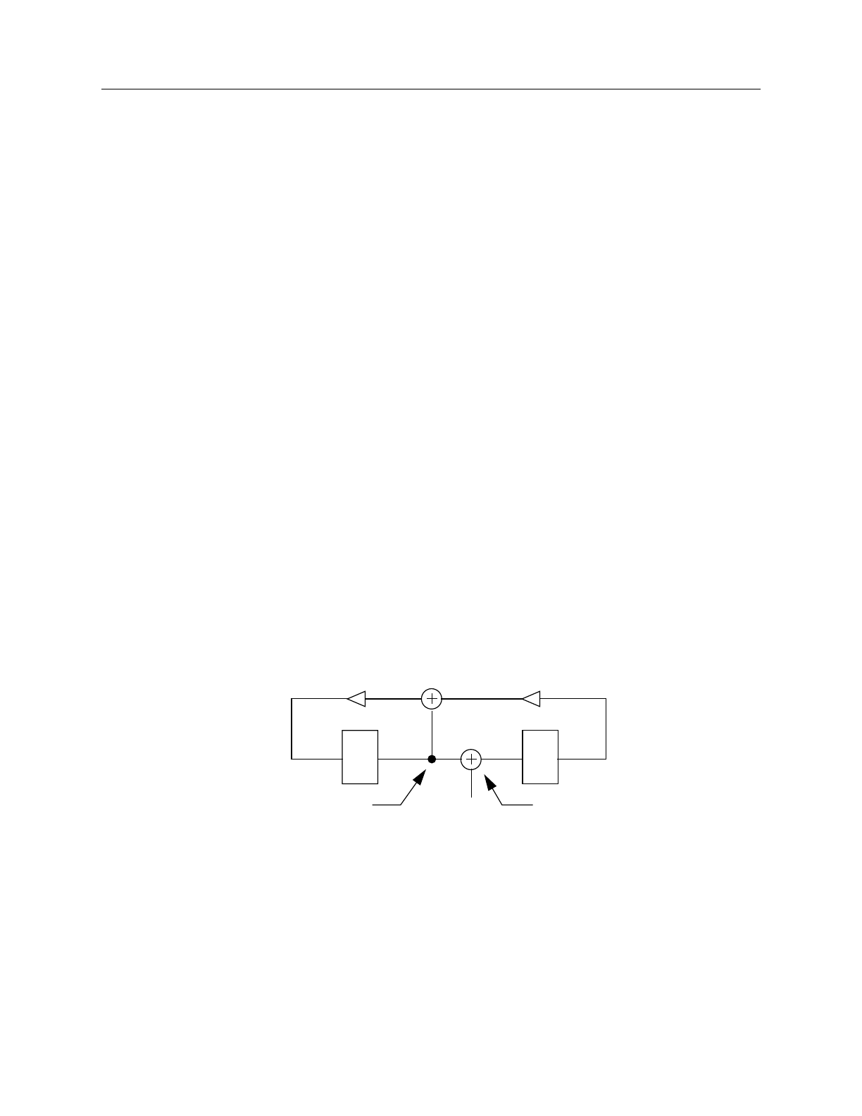
FastScan and FlexTest Reference Manual, V8.6_4
2-72
Add LFSR Connections Command Dictionary
Add LFSR Connections
Tools Supported: FastScan
Scope: Setup mode
Usage
ADD LFsr Connections primary_pin lfsr_name position...
Description
Connects an external pin to a Linear Feedback Shift Register (LFSR).
The Add LFSR Connections command connects a core logic pin to an LFSR. You
specify this pin with the primary_pin argument. LFSR bit positions have integer
numbers, where 0 indicates the least significant bit position. FastScan assumes
that the output of the 0 bit position connects to the input of the highest bit position.
If you select multiple bits of a Pseudo-Random Pattern Generator (PRPG) for the
position argument, the tool assumes they are all exclusive-ORed together to create
the value for the pin.
If you determine that multiple primary_pins must connect to a bit position of a
Multiple Input Signature Register (MISR), you must issue a separate Add LFSR
Connections command for each pin. FastScan assumes the pins are all exclusive-
ORed together to create the value for the next MISR input. FastScan also assumes
that the physical placement of the MISR connections is after the tapping points as
shown in Figure 2-1.
Figure 2-1. MISR placement
You can use the Report LFSRs command to display all the LFSRs with their
current values and tap positions.
You use this command primarily for simulating Built-In Self Test (BIST)
circuitry.
SR SR
IN MISRTapping Point

Command Dictionary Add LFSR Connections
FastScan and FlexTest Reference Manual, V8.6_4 2-73
Arguments
•primary_pin
A required string that specifies the name of the core logic pin that you want to
connect to the LFSR specified by lfsr_name.
•lfsr_name
A required string that specifies the name of the LFSR to which you want to
connect the primary_pin.
•position
A required repeatable integer that specifies the bit positions of the lfsr_name at
whose outputs you wish to place connections. A bit position is an integer
number, where 0 indicates the least significant bit position. The tool assumes
the output of the 0 bit position connects to the input of the highest bit position.
Examples
The following example connects an LFSR to a scan-in pin and another LFSR to a
scan-out pin:
add lfsrs lfsr1 prpg 5 10 -serial -in
add lfsrs misr1 misr 5 15 -both -out
add lfsr taps lfsr1 1 3
add lfsr taps misr1 1 2
add lfsr connections scan_in.1 lfsr1 2
add lfsr connections scan_out.0 misr1 3
Related Commands
Add LFSRs
Add LFSR Taps Delete LFSR Connections
Report LFSR Connections

FastScan and FlexTest Reference Manual, V8.6_4
2-74
Add LFSR Taps Command Dictionary
Add LFSR Taps
Tools Supported: FastScan
Scope: Setup mode
Usage
ADD LFsr Taps lfsr_name position...
Description
Adds the tap configuration to a Linear Feedback Shift Register (LFSR).
The Add LFSR Taps command sets the tap configuration of an LFSR. LFSR bit
positions have integer numbers, where 0 indicates the least significant bit position.
FastScan assumes the output of the 0 bit position connects to the selected tap
points and that the 0 bit position cannot itself be a tap point.
You can use the Report LFSRs command to display all the LFSRs with their
current values and tap positions. You can change the default setting of the
tap_type switches by using the Setup LFSRs command.
You use this command primarily for simulating Built-In Self Test (BIST)
circuitry.
Arguments
•lfsr_name
A required string that specifies the name of the LFSR on which you want to
place the taps.
•position
A required repeatable integer that specifies the bit positions of the lfsr_name at
whose outputs you wish to place the taps.
Examples
The following example places taps on the newly added LFSRs:
add lfsrs lfsr1 prpg 5 10 -serial -in
add lfsrs misr1 misr 5 15 -both -out
add lfsr taps lfsr1 1 3
add lfsr taps misr1 1 2


FastScan and FlexTest Reference Manual, V8.6_4
2-76
Add LFSRs Command Dictionary
Add LFSRs
Tools Supported: FastScan
Scope: Setup mode
Usage
ADD LFsrs lfsr_name {Prpg | Misr}length seed [-Both | -Serial | -Parallel]
[-Out | -In]
Description
Adds Linear Feedback Shift Registers (LFSRs) for use as Pseudo-Random Pattern
Generators (PRPGs) or Multiple Input Signature Registers (MISRs).
The Add LFSRs command defines LFSRs, which FastScan uses as PRPGs, to
create pseudo-random values for the Built-In Self Test (BIST) patterns or as
MISRs to compact responses.
You specify the LFSR’s shift technique by using one of the following shift_type
switches: -Both, -Serial, or -Parallel. You specify the placement of the exclusive-
OR taps by using one of the following tap_type switches: -Out or -In. You can
change the default setting of the shift_type and tap_type switches by using the
Setup LFSRs command.
You use this command primarily for simulating Built-In Self Test (BIST)
circuitry.
Arguments
•lfsr_name
A required string that specifies the name that you want to assign to the LFSR.
•Prpg
A literal that indicates the LFSR functions as a PRPG.
•Misr
A literal that indicates the LFSR functions as a MISR.
•length
A required integer, greater than 1, specifying the number of bits in the LFSR.

Command Dictionary Add LFSRs
FastScan and FlexTest Reference Manual, V8.6_4 2-77
•seed
A required, right-justified, hexadecimal number, greater than 0, specifying the
initial state of the LFSR.
The following lists the three shift_type switches of which you can choose only
one.
•-Both
An optional switch specifying that the LFSR shifts both serially and in
parallel. This is the default unless you change it with the Setup LFSRs
command.
•-Serial
An optional switch specifying that the LFSR shifts serially the number of
times equal to the length of the longest scan chain for each scan pattern.
•-Parallel
An optional switch specifying that the LFSR parallel shifts once for each
scan pattern.
The following lists the two tap_type switches of which you can only choose one.
•-Out
An optional switch specifying that the exclusive-OR taps reside outside the
register path. This is the default unless you change it with the Setup LFSRs
command.
•-In
An optional switch specifying that the exclusive-OR taps reside in the
register path.
Examples
The following example defines an LFSR to be a PRPG and another LFSR to be a
MISR:
add lfsrs lfsr1 prpg 5 10 -serial -in
add lfsrs misr1 misr 5 15 -both -out
add lfsr taps lfsr1 1 3
add lfsr taps misr1 1 2


Command Dictionary Add Lists
FastScan and FlexTest Reference Manual, V8.6_4 2-79
Add Lists
Tools Supported: FastScan and FlexTest
Scope: Atpg, Fault, and Good modes
Usage
ADD LIsts pin_pathname...
Description
Adds pins to the list of pins on which to report.
The Add Lists command adds pins to a list of pins on which to report, and is
useful when debugging. In the Good simulation mode, the command reports the
value of the good machine. In the Fault simulation mode and ATPG modes, the
command reports the value of the good machine as well as the value of the faulty
machine if the two values differ.
You can display the list of pins by using the Report Lists command. You can
review the stored logic values of the reported pins in a list file. You specify the list
filename with the Set List File command. When switching to Setup mode, the tool
discards all pins from the report list.
Arguments
•pin_pathname
A required repeatable string that specifies the output pins whose values you
want to report during either Good or Fault simulation modes.
Examples
The following example reports the value of an output instance pin in Good
simulation mode for an external pattern source to a file for review.
set system mode good
set pattern source external pattern1
add lists i_1006/o
set list file listfile
run

FastScan and FlexTest Reference Manual, V8.6_4
2-80
Add Lists Command Dictionary
The following is an example list file reporting on one pin in the Good system
mode:
// /I_1006/O
// |
//-------
// 0 1
// 1 1
// 2 0
// 3 0
// 4 1
// 5 1
The Good system mode shows the good value of the pin. FastScan shows the
values at each test pattern; FlexTest shows them at each timeframe of each test
cycle.
The following is an example list file reporting on one pin in the Fault system
mode:
// /I_1006/O
// |
//-------
// 0 1
// 1 1
// 2 0
// 2 1 {/I_1006/I2@0}
// 3 0
// 3 1 {/I_1006/I2@0}
// 4 1
// 4 0 {/I_1006/I3@1}
The Fault system mode shows the good value of the pin along with the faulty
value only if the two values differ. The name inside “{}” is the pin pathname of a
fault site and its stuck-at value.
Related Commands
Delete Lists
Report Lists Set List File

Command Dictionary Add Mos Direction
FastScan and FlexTest Reference Manual, V8.6_4 2-81
Add Mos Direction
Tools Supported: FastScan and FlexTest
Scope: Setup mode
Prerequisites: This command can only operate on a Spice design.
Usage
ADD MOs Direction subckt_name instance_name source_port drain_port
Description
Assigns the direction of a bi-directional MOS transistor.
The Add Mos Direction command sets the direction of a bi-directional transistor
in the Spice design or library. The direction is from SOURCE to DRAIN port.
Arguments
•subckt_name
A required string that specifies the name of the SUBCKT that contains the
instance for which you are setting the direction.
•instance_name
A required string that specifies the name of the instance within the SUBCKT
for which you are setting the direction.
•source_port
A required string that specifies the name of the SOURCE port.
•drain_port
A required string that specifies the name of the DRAIN port.
Examples
The following example assigns the direction of the instance (K5) bi-direction
MOS transistor of the subskt FADD2 from the port IN0 to the port IN1:
add mos direction FADD2 K5 IN0 IN1


Command Dictionary Add Net Property
FastScan and FlexTest Reference Manual, V8.6_4 2-83
Add Net Property
Tools Supported: FastScan and FlexTest
Scope: Setup mode
Prerequisites: This command can only operate on a Spice design.
Usage
ADD NEt Property net_name {-VDD | -GND}
Description
Defines the net in the Spice design and library as VDD or GND.
The Add Net Property command defines the specified net as VDD or GND in the
Spice design and Spice library by adding a property.
Arguments
•net_name
A required string that specifies the name of the net which you want to define as
VDD or GND.
•-VDD | -GND
A required switch that specifies whether the net is VDD or GND.
Examples
The following example defines the ZGND net as GND in the loaded Spice design
and Spice library.
add net property ZGND -gnd
Related Commands
Delete Net Property Report Net Properties

FastScan and FlexTest Reference Manual, V8.6_4
2-84
Add Nofaults Command Dictionary
Add Nofaults
Tools Supported: FastScan and FlexTest
Scope: Setup mode
Usage
ADD NOfaults {pathname... [-Instance | -Module] [-Stuck_at {01 | 0 | 1}]}
[-Keep_boundary]
Description
Places nofault settings either on pin pathnames, pin names of specified instances,
or modules.
By specifying pathnames of pins, instances of, or modules while in Setup mode,
the Add Nofaults command places a nofault setting either on the specific pins or
on boundary and internal pins of the instances/modules. All added nofault pin
pathnames are in the user class. If you do not specify a stuck-at value, then the
tool places a nofault setting on both stuck-at values. When you add faults with the
Add Faults command after you issue the Add Nofaults command, the specified
pin pathnames or boundary and internal pins of instances/modules cannot be sites
for those added faults. Once you add nofault settings, the tool deletes the flattened
model.
Arguments
•pathname
A repeatable string that specifies the pin pathnames or the instance/module
pathnames for which you want to assign nofault settings. If the pathnames you
specify are instance pathnames, you must use the -Instance switch. If the
pathnames you specify are module pathnames, you must use the -Module
switch.
!
Caution
Once you add nofault settings, the tool loses all information added
after flattening the model, such as ATPG functions and
constraints, due to the deletion of the flattened model. Adding
nofault settings should be done prior to flattening the model.

Command Dictionary Add Nofaults
FastScan and FlexTest Reference Manual, V8.6_4 2-85
•-Instance
An optional switch specifying that the pathname arguments are instance
pathnames. In this case, the command places nofault settings on all boundary
and internal pins of the specified instances (unless the -Keep_boundary switch
is used).
•-Module
An optional switch specifying the that pathname arguments are module names
and all instances of these modules are affected.
•-Stuck_at 01 | 0 | 1
An optional switch and literal pair that specifies to which stuck-at values you
want to assign a nofault setting. The choices for stuck-at values are as follows:
01 — A literal that specifies the placement of a nofault setting on both the
“stuck-at-0” and “stuck-at-1” faults. This is the default.
0 — A literal that specifies the placement of a nofault setting only on the
“stuck-at-0” faults.
1 — A literal that specifies the placement of a nofault setting on the “stuck-
at-1” faults.
•-Keep_boundary
An optional switch that specifies that nofault is applied to the inside of the
specified instance/module and creates faults at the boundary pins of these
instances/modules. This option does not apply to nofaults on pin pathnames.
Examples
The following example adds nofault settings to all the pins in the instance so when
you add all faults to the circuit for an ATPG run, the tool will not place faults on
the pins of that instance:
add nofaults i_1006 -instance
set system mode atpg
add faults -all
run

FastScan and FlexTest Reference Manual, V8.6_4
2-86
Add Nofaults Command Dictionary
The next example places nofault settings on all the design pins within all instances
of wired cone logic, adds all faults to the circuit, and performs an ATPG run such
that FastScan places nofaults on the wired cone logic pins:
set system mode atpg
add nofault -wired
add faults -all
run
Related Commands
Delete Nofaults Report Nofaults

Command Dictionary Add Nonscan Handling
FastScan and FlexTest Reference Manual, V8.6_4 2-87
Add Nonscan Handling
Tools Supported: FlexTest
Scope: Setup mode
Prerequisites: Your design must have scan in order to be able to add nonscan
handling.
Usage
ADD NOnscan Handling learned_behavior element_pathname...
[-Instance | -Module]
Description
Overrides behavior classification of non-scan elements that FlexTest learns during
the design rules checking process.
When you exit the Setup mode, the design rules checker classifies each non-scan
element into a type of learned behavior. FlexTest then uses this information when
simulating the operation of the scan chains.
However, due to limitations on modeling and simulation capabilities, FlexTest
can sometimes pessimistically classify a non-scan element. If you want to
override the behavior classification of a particular non-scan element, you can use
the Add Nonscan Handling command.
The Set Nonscan Model command continues to have the same effect on HOLD
and INITX for behaviors learned from the design rules checker, or that you set
with the Add Nonscan Handling command.
Arguments
•learned_behavior
A required literal argument that specifies the classification of learned behavior
that you want to assign to the named non-scan element. The choices for the
learned_behavior argument, from which you can select only one, are:
TIE0 — A literal that specifies for the non-scan element to always be at a
low state when FlexTest operates the scan chain.
TIE1 — A literal that specifies for the non-scan element to always be at a
high state when FlexTest operates the scan chain.

FastScan and FlexTest Reference Manual, V8.6_4
2-88
Add Nonscan Handling Command Dictionary
Hold — A literal that specifies for the state of this type of element to
remain undisturbed when FlexTest operates the scan chain.
INITX — A literal specifying that the logic state of the non-scan element is
unknown when FlexTest finishes operating the scan chain.
INIT0 — A literal that specifies for the output of this non-scan element to
be a low state when FlexTest finishes operating the scan chain.
INIT1 — A literal that specifies for the output of this non-scan element to
be a high state when FlexTest finishes operating the scan chain.
•element_pathname
A required repeatable string that specifies the pathname to the non-scan
element whose learned behavior you want to reclassify during the time
FlexTest operates the scan chain.
•-Instance
An optional literal that specifies that the element_pathname(s) specified are
instance pathnames. This is the default upon invocation.
•-Module
An optional literal that specifies that the element_pathname(s) specified are
module names. All instances with the specified modules are affected by this
command as well as the Delete Nonscan Handling command.
Examples
The following example specifies for FlexTest to assume that the given non-scan
element is always at a high state, regardless of how the design rules checker
determined its behavior:
add nonscan handling tie0 i_6_16
report nonscan handling
TIE0 I_6_16
Related Commands
Delete Nonscan Handling
Report Nonscan Handling Set Nonscan Model

Command Dictionary Add Notest Points
FastScan and FlexTest Reference Manual, V8.6_4 2-89
Add Notest Points
Tools Supported: FastScan
Scope: Atpg, Fault, and Good modes
Usage
ADD NOtest Points pin_pathname...
Description
Adds circuit points to list for exclusion from testability insertion.
The Add Notest Points command excludes the specified cell output pins from use
as controllability and observability insertion points. If the selected pin is already a
control or observe point, an error occurs when you issue this command. You can
use the Report Notest Points command to display all the pins in this list.
You use this command primarily for simulating Built-In Self Test (BIST)
circuitry.
Arguments
•pin_pathname
A required repeatable string that lists the output pins that you do not want to
use for insertion of controllability and observability.
Examples
The following example specifies output pins that FastScan cannot use for
testability insertion:
set system mode fault
add notest points i_1006/o i_1008/o i_1009/o
insert testability
report control points
report observe points
Related Commands
Delete Notest Points
Insert Testability Report Notest Points

FastScan and FlexTest Reference Manual, V8.6_4
2-90
Add Observe Points Command Dictionary
Add Observe Points
Tools Supported: FastScan
Scope: Atpg, Fault, and Good modes
Usage
ADD OBserve Points pin_pathname...
Description
Adds observe points to output pins.
The Add Observe Points command adds observe points to the output pins of cells,
providing a way to evaluate the effect of making the cell output pin an observable
point. After you issue this command, the tool discards all of the patterns in the
current scan test pattern set. After insertion, the tool discards the current fault list,
so you must recreate the fault list if you wish to perform additional fault
simulation. If you enter Setup mode, the tool deletes any observe points you
added. Moreover, you cannot generate test patterns after adding observe points.
You use this command primarily for simulating Built-In Self Test (BIST)
circuitry.
Arguments
•pin_pathname
A required repeatable string that specifies a list of output pins for which you
want to insert observe points.
Examples
The following example adds an observe point to an output pin to evaluate the
effects of its value:
set system mode atpg
add observe points i_1006/o
analyze control
report control data


FastScan and FlexTest Reference Manual, V8.6_4
2-92
Add Output Masks Command Dictionary
Add Output Masks
Tools Supported: FastScan and FlexTest
Scope: Setup mode
Usage
ADD OUtput Masks primary_output...
Description
Ignores any fault effects that propagate to the primary output pins you name.
The tool uses primary output pins as the observe points during the fault detection
process. When you mask a primary output pin, you inform the tool to mark that
pin as an invalid observation point during the fault detection process. This
command allows you the ability to flag primary output pins that do not have
strobe capability. The tool classifies the faults whose effects only propagate to that
observation point as Atpg_Untestable (AU).
Arguments
•primary_output
A required repeatable string that specifies the name of the primary output pin
you want to mask.
Examples
The following example specifies the primary output pins that will not have the
strobe capability on the hardware tester:
add output masks qb1 qb2 qb3
Related Commands
Delete Output Masks Report Output Masks

Command Dictionary Add Pin Constraints
FastScan and FlexTest Reference Manual, V8.6_4 2-93
Add Pin Constraints
Tools Supported: FastScan and FlexTest
Scope: Setup mode
Usage
ADD PIn Constraints primary_input_pin... constraint_format
Description
Adds pin constraints to primary inputs and input channel to I/O pins.
The Add Pin Constraints command performs slightly differently depending on
whether you use FastScan or FlexTest. The following paragraphs describe how
the command operates for each tool.
FastScan Specifics
The Add Pin Constraints command restricts the chosen pins to a specific value
during the ATPG process.
For every regular primary input for which you do not specify a constraint by using
the Add Pin Constraints command, saving patterns will automatically default to
the NR constraint format except where the CRO and CR1 formats are used.
You can constrain a clock pin to its off-state to prevent its use as a capture clock
during the ATPG process. The constrained value must be the same as the clock
off-state or an error occurs. You may wish to use a return format if the pin utilizes
clock timing in the test_setup procedure (this is an AVI requirement).
You can also constrain a scan-in pin. You cannot constrain an equivalent pin, with
the exception of a simple equivalent pin. If you constrain a primary input to be a
constant Z, but it does not connect to a tri-state net, FastScan converts the pin
value to a constant X; FastScan also displays a warning message indicating that it
performed the conversion.
Note
The NR constraint format is not available from the FastScan
command line interface.

FastScan and FlexTest Reference Manual, V8.6_4
2-94
Add Pin Constraints Command Dictionary
You can force constrained pins in test procedures to the opposite of the
constrained value, provided you put the pin back again to its constrained value by
the end of the procedure. The DRC process keeps track of which pins are forced to
the opposite of their constrained value in the test procedures.
FlexTest Specifics
The Add Pin Constraints command adds cycle behavior constraints to the
specified primary input.
For every primary input for which you do not specify a constraint by using the
Add Pin Constraints command, FlexTest automatically uses the default format
type NR, with a period of 1, and offset of 0. You can change the default format by
using the Setup Pin Constraints command.
You specify the test cycle width by using the Set Test Cycle command.
You can constrain a clock pin to its off-state to prevent its use as a capture clock
during the ATPG process. The constrained value must be the same as the clock
off-state or an error occurs. All clocks with a 0 off-state should have a return-zero
waveform. Likewise, all clocks with a 1 off-state should have a return-one
waveform. You cannot constrain an equivalent pin, with the exception of a NR
format pins.
FlexTest provides 11 constraint formats from which you choose the constant
value that you want to apply to an primary input. Further, these constraint formats
(waveform types) group into three waveform classes which apply to all automatic
test equipment:
Group 1 Non-return waveform; the pin value may change only once.
Includes the NR, C0, C1, CZ, and CX constraint formats. Group 1
waveforms require you to specify the period and offset. If not
specified for C0, C1, CX, and CZ, FlexTest assumes the period is
1 and the offset is 0.
Group 2 Return-zero waveform; the pin value may rise to a 1 and then
return to a 0. Includes the R0, SR0, and CR0 constraint formats.
Group 2 waveforms require you to specify the period,offset, and
pulse width.

Command Dictionary Add Pin Constraints
FastScan and FlexTest Reference Manual, V8.6_4 2-95
Group 3 Return-one waveform; the pin value may fall to a 0 and then
return to a 1. Includes the R1, SR1, and CR1 constraint formats.
Group 3 waveforms require you to specify the period,offset, and
pulse width.
The “Arguments” subsection that follows describes the constraint formats in more
detail.
Arguments
•primary_input_pin
A required repeatable string that specifies the primary input pins that you want
to constrain.
•constraint_format
An argument that specifies the constant value with which you want to
constrain the primary input pins. The constraint format choices are as follows:
NR period offset (FlexTest Only) — A literal and two integer triplet that
specifies application of the non-return waveform value to the chosen
primary input pins. The test pattern set you provide determines the actual
value FlexTest assigns to the pins.
C0 — A literal that specifies application of the constant 0 to the chosen
primary input pins. For FlexTest, if the value of the pins change during the
scan operation, FlexTest uses the non-return waveform.
C1 — A literal that specifies application of the constant 1 to the chosen
primary input pins. For FlexTest, if the value of the pins change during the
scan operation, FlexTest uses the non-return waveform.
CZ — A literal that specifies application of the constant Z (high-
impedance) to the chosen primary input pins. For FlexTest, if the value of
the pins change during the scan operation, FlexTest uses the non-return
waveform.
CX — A literal that specifies application of the constant X (unknown) to
the chosen primary input pins.
FastScan Specifics:
FastScan does not use the specified primary_input_pin for control.

FastScan and FlexTest Reference Manual, V8.6_4
2-96
Add Pin Constraints Command Dictionary
FlexTest Specifics:
If the value of the pins change during the scan operation, FlexTest uses the
non-return waveform.
R0 period offset width (FlexTest Only) — A literal and three integer
quadruplet that specifies application of one positive pulse per period.
SR0 period offset width (FlexTest Only) — A literal and three integer
quadruplet that specifies application of one suppressible positive pulse
during non-scan operation.
CR0 period offset width (FlexTest Only) — A literal and three integer
quadruplet that specifies no positive pulse during non-scan operation.
CR0 (FastScan Only) — A literal that specifies a constant that returns to 0;
FastScan uses this constant only when formatting the patterns. The ATPG
process treats CR0 as a C0.
R1 period offset width (FlexTest Only) — A literal and three integer
quadruplet that specifies application of one negative pulse per specified
period during non-scan operation.
SR1 period offset width (FlexTest Only) — A literal and three integer
quadruplet that specifies application of one suppressible negative pulse.
CR1 period offset width (FlexTest Only) — A literal and three integer
quadruplet that specifies no negative pulse during non-scan operation.
CR1 (FastScan Only)— A literal that specifies a constant that returns to 1;
FastScan uses this constant only when formatting the patterns. The ATPG
process treats CR1 as a C1.
Where:
period (FlexTest Only) — An integer that specifies the period in terms of
the total number of test cycles. The Set Test Cycle command defines the
number of timeframes per test cycle.
offset (FlexTest Only) — An integer that specifies the timeframe in which
values start to change in each cycle.
width (FlexTest Only) — An integer that specifies the pulse width of the
pulse type waveform in number of timeframes.

Command Dictionary Add Pin Constraints
FastScan and FlexTest Reference Manual, V8.6_4 2-97
Examples
FastScan Example
The following FastScan example constrains two primary inputs to be at a constant.
add pin constraints indata2 c1
add pin constraints indata4 c0
FlexTest Example
The following FlexTest example adds a cycle behavior constraint to a primary
input. This primary input will always have one positive pulse per cycle. The rising
edge is at time 0 (offset is 0), and the falling edge is at time 1 (pulse width is 1). Its
cycle period is the same as one test cycle consisting of two timeframes:
set test cycle 2
add pin constraints ph1 r0 1 0 1
Related Commands
Delete Pin Constraints
Report Pin Constraints Set Test Cycle (FT)
Setup Pin Constraints (FT)

FastScan and FlexTest Reference Manual, V8.6_4
2-98
Add Pin Equivalences Command Dictionary
Add Pin Equivalences
Tools Supported: FastScan and FlexTest
Scope: Setup mode
Usage
For FastScan
ADD PIn Equivalences reference_pin {equivalent_pin... | {-Invert
inverted_pin...}}...
For FlexTest
ADD PIn Equivalences target_pin... [-Invert] reference_pin
Description
Adds restrictions to primary inputs such that they have equal or inverted values.
The Add Pin Equivalences command performs slightly differently depending on
whether you use FastScan or FlexTest. The following paragraphs describe how
the command operates for each tool.
FastScan Specifics
For FastScan the Add Pin Equivalences command specifies that all primary input
pins named subsequent to the reference_pin take on the value (or the inverted
value) of the reference_pin. You can specify both pin equivalences and inversions
in one command line by listing all equivalent_pins before the -Invert switch and
all inverted_pins after the -Invert switch.
Constrained pins may not be equivalent pins.
FlexTest Specifics
For FlexTest the Add Pin Equivalences command specifies that all primary input
pins named prior to the reference_pin take on the value (or the inverted value) of
the reference_pin. You can only specify either pin equivalences or inversions in
one command line. If you need to specify both pin equivalences and inversions,
you need to enter the command twice.

Command Dictionary Add Pin Equivalences
FastScan and FlexTest Reference Manual, V8.6_4 2-99
Arguments
•reference_pin
A required string specifying the name of the primary input pin whose value
you want the tool to use when determining the state value of the other named
primary input pins.
•equivalent_pin (FastScan Only)
A repeatable string that lists the primary input pins whose values you want to
equal the reference_pin. You must list all equivalent_pins before the -Invert
inverted_pin argument.
•target_pin (FlexTest Only)
A repeatable string that lists the primary input pins whose values you want to
either equal or invert with respect to reference_pin.
•-Invert inverted_pin (FastScan Only)
A switch and repeatable string pair that lists the primary input pins whose
values you want to invert with respect to reference_pin.
•target_pin (FlexTest Only)
A repeatable string that lists the primary input pins whose values you want to
either equal or invert with respect to reference_pin.
•-Invert (FlexTest Only)
An optional switch that specifies for FlexTest to hold the target_pin value to
the opposite state of the reference_pin value. If you use this switch, you must
enter it immediately prior to the reference_pin value.
Examples
The following examples show how the two tools differ with respect to the Add Pin
Equivalences command. Both examples provide the following results:
indata3 is equivalent to indata2
indata4 is inverted with respect to indata2
FastScan Example
add pin equivalences indata2 indata3 -invert indata4


Command Dictionary Add Pin Strobes
FastScan and FlexTest Reference Manual, V8.6_4 2-101
Add Pin Strobes
Tools Supported: FlexTest
Scope: Setup mode
Usage
ADD PIn Strobes strobe_time primary_output_pin... [-Period integer]
Description
Adds strobe time to the primary outputs.
The Add Pin Strobes command adds a strobe time for each test cycle of the
specified primary output pins. Any primary outputs without specified strobe times
use the default strobe time. For nonscan circuits, the default strobe time is the last
timeframe of each test cycle. For scan circuits, FlexTest designates time 1 of each
test cycle as the default strobe time for every primary output. You can change the
default time frame for non-scan operations by using the -Period option.
Arguments
•strobe_time
A required integer that specifies the strobe time for each test cycle. This
number should not be greater than the period set with the Set Test Cycle
command.
•primary_output_pin
A required repeatable string that specifies a list of primary output pins.
•-Period integer
Specifies the number of cycles for the period of each strobe. The default is 1.
This option is only available for non-scan operations.
Examples
The following example adds time 1 as the strobe time of primary output pin
outdata1.
set test cycle 3
add pin strobes 1 outdata1


Command Dictionary Add Primary Inputs
FastScan and FlexTest Reference Manual, V8.6_4 2-103
Add Primary Inputs
Tools Supported: FastScan and FlexTest
Scope: Setup mode
Usage
ADD PRimary Inputs net_pathname... [-Cut] [-Module]
Description
Adds primary inputs.
The Add Primary Inputs command adds an additional primary input to each
specified net. Once added, the tool designates them as user class primary inputs,
as opposed to the primary inputs described in the original netlist, which it
designates as system class primary inputs. Use the -Cut option to disconnect the
original drivers of the net so that the added primary input becomes the only driver
to the net. Otherwise, if there are other drivers besides the newly added primary
input, the tool treats this net as a wired net. You can display the user class, system
class, or full classes of primary inputs using the Report Primary Inputs command.
Arguments
•net_pathname
A required repeatable string specifying the pathname of the nets to which you
want to add primary inputs.
•-Cut
An optional switch that specifies disconnection of the original drivers of the
net, making the added primary input the only driver of the net. The design must
be flattened prior to using this option with the Flatten Model command.
•-Module
An optional switch that specifies addition of the primary input to the specified
nets in all modules.

FastScan and FlexTest Reference Manual, V8.6_4
2-104
Add Primary Inputs Command Dictionary
Examples
The following example adds two new primary inputs to the circuit and places
them in the user class of primary inputs:
add primary inputs indata2 indata4
Related Commands
Delete Primary Inputs
Report Primary Inputs Write Primary Inputs (FT)

Command Dictionary Add Primary Outputs
FastScan and FlexTest Reference Manual, V8.6_4 2-105
Add Primary Outputs
Tools Supported: FastScan and FlexTest
Scope: Setup mode
Usage
ADD PRimary Outputs net_pathname...
Description
Adds primary outputs.
The Add Primary Outputs command adds an additional primary output to each
specified net. Once added, the tool defines them as user class primary outputs. The
tool defines the primary outputs described in the original netlist as system class
primary outputs. You can display the user class, system class, or full classes of
primary outputs using the Report Primary Outputs command.
Arguments
•net_pathname
A required repeatable string that specifies the nets to which you want to add
primary outputs.
Examples
The following example adds a new primary output to the circuit and places it in
the user class of primary outputs:
add primary outputs outdata1
Related Commands
Delete Primary Outputs
Report Primary Outputs Write Primary Outputs (FT)

FastScan and FlexTest Reference Manual, V8.6_4
2-106
Add Random Weights Command Dictionary
Add Random Weights
Tools Supported: FastScan
Scope: Atpg, Fault, and Good modes
Usage
ADD RAndom Weights percentage_of_1_states primary_input_pin...
Description
Specifies the random pattern weighting factors for primary inputs.
The Add Random Weights command specifies the percentage of primary input
patterns that you want to place at a 1-state during random pattern fault simulation.
You can use the Report Random Weights command to display the values in the
random weight list for specific primary inputs.
If you delete the flattened model, you also delete all members of the random
weight list.
You use this command primarily for simulating Built-In Self Test (BIST)
circuitry.
Arguments
•percentage_of_1_states
A required floating point number between 0.0 and 100.0. FastScan rounds the
number to the nearest whole number. The default value is 50.0.
•primary_input_pin
A required repeatable string that specifies the names of the primary input pins
to which you want to apply the weighting factor.

Command Dictionary Add Random Weights
FastScan and FlexTest Reference Manual, V8.6_4 2-107
Examples
The following example sets the weighting factor for primary inputs in order to
perform testability analysis:
set system mode fault
add random weights 100.0 indata2
add random weights 25.0 indata4
report random weights
set random patterns 612
insert testability
Related Commands
Delete Random Weights
Report Random Weights Set Random Weights

FastScan and FlexTest Reference Manual, V8.6_4
2-108
Add Read Controls Command Dictionary
Add Read Controls
Tools Supported: FastScan and FlexTest
Scope: Setup mode
Usage
ADD REad Controls 0 | 1primary_input_pin...
Description
Adds an off-state value to read control lines.
The Add Read Controls command defines the circuit read control lines and
assigns their off-state values. The off-state value of the pins that you specify must
be sufficient to keep the RAM outputs stable. You can use clocks, constrained
pins, or equivalent pins as read control lines if their off-states are the same.
Arguments
•0
A literal specifying that 0 is the off-state value for the read control lines.
•1
A literal specifying that 1 is the off-state value for the read control lines.
•primary_input_pin
A required repeatable string that specifies the primary input pins you designate
as read control lines and to which you are assigning the given off-state value.
Examples
The following example assigns an off-state value of 0 to two read control lines, r1
and r2:
add read controls 0 r1 r2
set system mode atpg
add faults -all
run


FastScan and FlexTest Reference Manual, V8.6_4
2-110
Add Scan Chains Command Dictionary
Add Scan Chains
Tools Supported: FastScan and FlexTest
Scope: Setup mode
Prerequisites: You must define the scan chain group with the Add Scan Groups
command prior to using this command.
Usage
ADD SCan Chains {chain_name group_name primary_input_pin
primary_output_pin}...
Description
Adds a scan chain to a scan group.
The Add Scan Chains command defines a scan chain that exists in the design. A
scan chain references the name of a scan chain group, which you must define prior
to issuing this command.
You can define multiple scan chains on one command line by repeating the
complete sequence of arguments for each scan chain.
Arguments
•chain_name
A required string that specifies the name of the scan chain you want added to
the scan group.
•group_name
A required string that specifies the name of the scan chain group to which you
are adding the scan chain.
•primary_input_pin
A required string that specifies the input pin of the scan chain.
•primary_output_pin
A required string that specifies the output pin of the scan chain.

Command Dictionary Add Scan Chains
FastScan and FlexTest Reference Manual, V8.6_4 2-111
Examples
The following example defines two scan chains (chain1 and chain2) that belong to
the same scan group (group1):
add scan groups group1 scanfile
add scan chains chain1 group1 indata2 testout2
add scan chains chain2 group1 indata4 testout4
Related Commands
Add Scan Groups
Delete Scan Chains Report Scan Chains

FastScan and FlexTest Reference Manual, V8.6_4
2-112
Add Scan Groups Command Dictionary
Add Scan Groups
Tools Supported: FastScan and FlexTest
Scope: Setup mode
Usage
ADD SCan Groups {group_name test_procedure_filename}...
Description
Adds a scan chain group to the system.
The Add Scan Groups command defines a scan chain group that contains scan
chains for the design. The procedures defined in test_procedure_filename control
the set of scan chains which make up the scan chain group.
If you specify “dummy” as the group name and provide a test procedure filename,
the tool expects the test procedure file to contain only the seq_transparent and
test_setup procedures. Doing so allows you to run ATPG without having a scan
structure currently in the design.
You can define multiple scan chain groups on one command line by repeating the
argument pair for each scan chain group.
Arguments
•group_name
A required string that specifies the name of the scan chain group that you want
to add to the system.
•test_procedure_filename
A required string that specifies the name of the test procedure file that contains
the information for controlling the scan chains in the specified scan chain
group.

Command Dictionary Add Scan Groups
FastScan and FlexTest Reference Manual, V8.6_4 2-113
Examples
The following example defines a scan chain group, group1, which loads and
unloads a set of scan chains, chain1 and chain2, by using the procedures in the
file, scanfile:
add scan groups group1 scanfile
add scan chains chain1 group1 indata2 testout2
add scan chains chain2 group1 indata4 testout4
Related Commands
Add Scan Chains
Delete Scan Groups Report Scan Groups

FastScan and FlexTest Reference Manual, V8.6_4
2-114
Add Scan Instances Command Dictionary
Add Scan Instances
Tools Supported: FlexTest
Scope: Setup mode
Usage
ADD SCan Instances instance_pathname...
Description
Adds sequential instances to the scan instance list.
The Add Scan Instances command specifies that FlexTest treat each sequential
instance you name as a scan cell during the ATPG process. If an instance is a
module instance, then FlexTest treats all sequential instances beneath it as scan
cells during the ATPG process.
This can be used to determine the test coverage on an experimental basis.
Arguments
•instance_pathname
A required repeatable string that specifies the instance pathnames that you
want to add to the scan instance list.
Examples
The following example adds two user-defined sequential instances to the scan
instance list and then runs ATPG to determine the resulting test coverage:
set system mode setup
add scan instances i_1006 i_1007
set system mode atpg
run
Related Commands
Delete Scan Instances Report Scan Instances

Command Dictionary Add Scan Models
FastScan and FlexTest Reference Manual, V8.6_4 2-115
Add Scan Models
Tools Supported: FlexTest
Scope: Setup mode
Usage
ADD SCan Models model_name...
Description
Adds sequential models to the scan model list.
The Add Scan Models command specifies for FlexTest to treat each sequential
instance identified by the model you name as a scan cell during the ATPG
process.
This can be used to determine the test coverage on an experimental basis.
Arguments
•model_name
A required repeatable string that specifies the model names that you want to
add to the scan model list. Enter the model names as they appear in the design
library.
Examples
The following example treats all instances of the specified library model as scan
cells and then runs ATPG to determine the resulting test coverage:
set system mode atpg
add scan models d_flip_flop
set system mode atpg
run
Related Commands
Delete Scan Models Report Scan Models

FastScan and FlexTest Reference Manual, V8.6_4
2-116
Add Slow Pad Command Dictionary
Add Slow Pad
Tools: FastScan
Scope: Atpg mode
Usage
ADD SLow Pad {pin_name [-Cell cell_name]} | -All
Description
Sets the specified I/O pin as a slow pad.
While running tests at high speed, as might be used for path delay test patterns, it
is not always safe to assume that the loopback path from internal registers, via the
I/O pad back to internal registers, can stabilize within a single clock cycle.
Assuming that the loopback path stabilizes within a single clock cycle may cause
problems verifying ATPG patterns or may lead to yield loss during testing.
To prevent a problem caused by this loopback, use the Add Slow Pad command to
modify the simulated behavior of the bidirectional pin, on a pin by pin basis. For a
slow pad, the simulation of the I/O pad is changed such that the value propagated
into the internal logic is X whenever the primary input is not driven. This causes
an X to be captured for all observation points dependent on the loopback value.
Arguments
•pin_name
A string specifying a primary I/O pin which the tool will mark as slow.
•-All
A switch specifying that the tool mark all I/O pins as slow.
•-Cell cell_name
An optional switch and literal pair that specifies that the instance name of each
instance of a cell of type cell_name will be added before the pin_name and
each resulting name looked up as an I/O pin.
Related Commands
Delete Slow Pad Report Slow Pads

Command Dictionary Add Tied Signals
FastScan and FlexTest Reference Manual, V8.6_4 2-117
Add Tied Signals
Tools Supported: FastScan and FlexTest
Scope: Setup mode
Usage
ADD TIed Signals {0 | 1 | X | Z}floating_object_name... [-Pin]
Description
Adds a value to floating signals or pins.
The Add Tied Signals command assigns a specific value to not-clearly-defined
floating signals or pins. If there are floating signals or pins in the design, a
warning appears when you leave the Setup mode. If you do not assign a specific
value, the tool ties the signal or pin values to the default value. You can change
the default tied value by using the Setup Tied Signals command.
When you add tied signals or pins, the tool places them into the user class. When
the netlist ties signals or pins to a value, the tool places them into the system class.
Arguments
•0
A literal that ties the floating nets or pins to logic 0 (low to ground).
•1
A literal that ties the floating nets or pins to logic 1 (high to voltage source).
•X
A literal that ties the floating nets or pins to unknown.
•Z
A literal that ties the floating nets or pins to high-impedance
Note
The tool will not tie a signal that is connected to I/O pins. This
causes a problem if you are considering UDD as an I/O pin.

FastScan and FlexTest Reference Manual, V8.6_4
2-118
Add Tied Signals Command Dictionary
•floating_object_name
A required repeatable string that specifies the floating nets or pins to which
you want to assign a specific value. The tool assigns the tied value to all
floating nets or pins in all modules that have the names that you specify.
If you do not specify the -Pin option, the tool assumes the name is a net name.
If you do specify the -Pin option, the tool assumes the name is a pin name.
•-Pin
An optional switch specifying that the floating_object_name argument that
you provide is a floating pin name.
Examples
The following example ties all floating signals in the circuit that have the net
names vcc and vdd, to logic 1 (tied to high):
add tied signals 1 vcc vdd
Related Commands
Delete Tied Signals
Report Tied Signals Setup Tied Signals

Command Dictionary Add Write Controls
FastScan and FlexTest Reference Manual, V8.6_4 2-119
Add Write Controls
Tools Supported: FastScan and FlexTest
Scope: Setup mode
Usage
ADD WRite Controls 0 | 1primary_input_pin...
Description
Adds an off-state value to specified write control lines.
The Add Write Controls command defines the circuit write control lines and
assigns their off-state values. The off-state value of the pins that you specify must
be sufficient to keep the RAM contents stable. You can use clocks, constrained
pins, or equivalent pins as write control lines if their off-states are the same.
Arguments
•0
A literal specifying that 0 is the off-state value for the primary_input_pins.
•1
A literal specifying that 1 is the off-state value for the primary_input_pins.
•primary_input_pin
A required repeatable string that specifies the primary input pins that are write
control lines to which you want to assign an off-state value.
Examples
The following example assigns an off-state to two write control lines, w1 and w2:
add write controls 0 w1 w2
set system mode atpg
add faults -all
run
Related Commands
Delete Write Controls Report Write Controls

FastScan and FlexTest Reference Manual, V8.6_4
2-120
Analyze Atpg Constraints Command Dictionary
Analyze Atpg Constraints
Tools Supported: FastScan and FlexTest
Scope: Atpg, Fault, and Good modes
Usage
For FastScan
ANAlyze ATpg Constraints {-AUto | -ALl | [{pin_pathname | gate_id# |
function_name}... [-Satisfy | -Exclusive]]} [-Bus]
For FlexTest
ANAlyze ATpg Constraints {-AUto | -ALl | {pin_pathname | gate_id# |
function_name}...} [-Bus]
Description
Specifies for FastScan or FlexTest to check the ATPG constraints you’ve created
for their satisfiability or for their mutual exclusivity.
If you issue the Analyze Atpg Constraints command without any arguments, the
default is -All.
When the command finishes, the tool displays a message indicating whether the
analysis passed, failed, or aborted the ATPG constraint analysis.
Arguments
The following lists the three methods for naming the objects for which you wish
to analyze the constraints. You can use any number of the three argument choices,
in any order.
FastScan Only - If you only specify an object name when you issue this
command, by default FastScan performs the satisfiability (-Satisfy) analysis.
•-Auto
An optional switch that automatically tries to locate the atpg constraint that
cannot be satisfied. The analysis checks to see if any single constraint cannot
be satisfied. Each constraint which cannot be satisfied (given the current abort
limit and other restrictions) is reported. Sometimes, each constraint can be

Command Dictionary Analyze Atpg Constraints
FastScan and FlexTest Reference Manual, V8.6_4 2-121
satisfied by itself, but some set of constraints cannot all be satisfied. In this
case, -Auto switch proceeds to a second analysis where it adds atpg constraints
to a set to create a minimal set that can’t be satisfied.
•-ALl
An optional switch that specifies for FastScan and FlexTest to perform the
ATPG analysis simultaneously for all the current ATPG constraints. This is the
command default if you do not specify an object name.
•pin_pathname
A repeatable string that specifies the pathname to the pin on which you are
analyzing the constraints.
•gate_id#
A repeatable integer that specifies the gate identification number of the gate on
which you wish to analyze the constraints.
•function_name
A repeatable string that specifies the name of a function you created with the
Add Atpg Functions command. If you generated the ATPG function with the
-Cell option and added constraints with the -Cell option, then the tool also
analyzes the constraints on all the cells affected by that ATPG function.
•-Satisfy (FastScan Only)
An optional switch that specifies for the ATPG process to attempt to create a
pattern that satisfies the selected ATPG constraint. This is the default if you
specify an object name without a switch. During the ATPG process, the test
generator does not consider the effect of other ATPG constraints or bus
contention prevention (unless you use the -Bus switch).
When the command finishes, FastScan displays a message indicating whether
the analysis passed (the ATPG process successfully generated a pattern), failed
(the ATPG process could not find any possible pattern), or aborted (the ATPG
process gave up on trying to find a successful pattern). If the analysis passes,
the data that FastScan simulated for the pattern is available in parallel pattern
zero (0).

FastScan and FlexTest Reference Manual, V8.6_4
2-122
Analyze Atpg Constraints Command Dictionary
•-Exclusive (FastScan Only)
An optional switch that specifies for the ATPG process to attempt to create a
pattern that sets the selected ATPG constraint at a value different from its
constrained value. This test’s intent is to ensure that such a pattern does not
exist. During the ATPG process, the test generator does not consider the effect
of other ATPG constraints or bus contention prevention (unless you use the
-Bus switch).
When the command finishes, FastScan displays a message indicating whether
the analysis passed (the ATPG process could not find any possible pattern),
failed (the ATPG process found another possible pattern), or aborted (the
ATPG process gave up on trying to find a successful pattern). If the analysis
fails, the data that FastScan simulated for the pattern is available in parallel
pattern zero (0).
•-Bus
An optional switch that specifies for the tool to consider bus contention
prevention during the ATPG process.
Examples
The following example for FastScan creates an ATPG constraint and then checks
for mutual exclusivity:
add atpg constraints 1 435
analyze atpg constraints 435 -exclusive
// ATPG constraint 435=1 failed mutual exclusivity check (data
in parallel pattern 0).
Related Commands
Add Atpg Constraints

Command Dictionary Analyze Bus
FastScan and FlexTest Reference Manual, V8.6_4 2-123
Analyze Bus
Tools Supported: FastScan and FlexTest
FastScan Scope: Atpg, Fault, and Good modes
FlexTest Scope: Drc mode
Usage
ANAlyze BUs {gate_id#... [-Exclusivity | -Prevention | -Zstate]} | -Drc_check |
-ALl | -Auto]
Description
Causes the tool to analyze the specified bus gates for contention problems.
If the bus passes the analysis, the tool displays a message indicating that it did so.
If the analysis aborts, the tool displays a message identifying the tri-state drivers
the tool was analyzing at abort time. If the bus fails the analysis, the tool displays
a message identifying the two offending tri-state drivers (the tri-state drivers
capable of being on simultaneously while driving different values).
The Set Contention Check On -Atpg command as well as Set Iddq Checks -Bus
(or -all) command cause ATPG to ensure that every bus is contention free during
deterministic test generation. Sometimes, this requirement cannot be met for
many or all of the faults targeted by ATPG, preventing you from obtaining
adequate fault coverage. When this happens, the Analyze Bus command
determines which bus or busses cannot be made contention free, so that you can
investigate the circuit around this bus to find out what is preventing contention
free tests.
When you issue this command, you must either specify a gate_id# value or one of
the global switches (-Drc_check or -All).
Arguments
•gate_id# -Exclusivity | -Prevention | -Zstate
A repeatable integer with an optional switch that specifies the identification
number of the bus gate and the type of analysis you want the tool to perform.

FastScan and FlexTest Reference Manual, V8.6_4
2-124
Analyze Bus Command Dictionary
The available switch choices are as follows:
-Exclusivity — An optional switch that specifies for the tool to analyze the
bus gate to see if it has mutual exclusivity. Mutual exclusivity means that
only one driver can simultaneously force a strong signal onto the bus.
Exclusivity is the default behavior when you specify a gate_id# value
without a corresponding switch.
-Prevention — An optional switch that specifies for the tool to analyze the
bus gate for its ability to attain a state of non-contention.
-Zstate — An optional switch that specifies for the tool to analyze the bus
gate for its ability to attain a high-impedance (Z) state.
•-Drc_check
A switch that specifies for the tool to run the design rule check process again to
categorize all buses and display the results. This is useful if you are changing
constraints or the abort limit in an attempt to pass bus checks rather than abort.
•-ALl
A switch that specifies for the tool to use the more extensive ATPG process to
place all the fail and abort buses in a noncontentious state. The internal
simulation data for this pattern is available in parallel pattern 0.
•-AUto
A switch that automatically tries to locate the bus that cannot be made
contention free. The analysis checks to see if any single bus cannot be made
contention free. Each bus which cannot be made contention free (given the
current abort limit and other restrictions) is reported to the user. Sometimes,
each bus can be satisfied by itself, but some set of busses cannot all be
satisfied. In this case, -Auto switch proceeds to a second analysis where it
creates a minimized set of buses that can’t be satisfied. The final, reduced set
of busses which cannot all be made contention free is reported.
Examples
The following example analyzes a bus that failed the regular bus contention
checking:
set system mode atpg
analyze bus 493

Command Dictionary Analyze Bus
FastScan and FlexTest Reference Manual, V8.6_4 2-125
The following example displays the current categorization of bus gates, and then
performs the prevention check on a specific bus gate:
set system mode drc
analyze bus -drc_check
// ATPG bus checking results: pass=1, bidi=1, fail=0, abort=0,
CPU time=0.00.
analyze bus 495 -prevention
// Controllability justification was successful (data
accessible using parallel_pattern 0).
// Pattern type: Basic_scan
Related Commands
Report Bus Data
Set Gate Level Set Contention Check

FastScan and FlexTest Reference Manual, V8.6_4
2-126
Analyze Control Command Dictionary
Analyze Control
Tools Supported: FastScan
Scope: Atpg, Fault, and Good modes
Usage
ANAlyze COntrol
Description
Calculates zero and one-state controllability.
The Analyze Control command calculates the zero and one–state controllability
by performing good circuit simulation for all gates in the design. Controllability
coverage (either one or zero) is a measure of the percentage of times a gate can
achieve a zero or one state for a set number of random patterns. You set the
number of applied random patterns with the Set Random Patterns command.
Gates should attain both zero and one states a reasonable number of times (the
control threshold), which you determine and set with the Set Control Threshold
command.
After issuing the Analyze Control command, you can display detailed information
about individual gates by using the Report Control Data command. This
information helps you identify circuit points that can increase the design’s
controllability. You can then evaluate the effects of making these points control
points by using the Add Control Points command and then reissuing the Analyze
Control command.
You use this command primarily for developing Built-In Self Test (BIST)
circuitry.
Examples
The following example calculates the controllable test coverage from gate values
which fail to achieve a state of minimum number of patterns:
set system mode atpg
set random patterns 612
set control threshold 5
analyze control
report control data


FastScan and FlexTest Reference Manual, V8.6_4
2-128
Analyze Control Signals Command Dictionary
Analyze Control Signals
Tools Supported: FastScan and FlexTest
Scope: All modes
Usage
ANAlyze COntrol Signals [-Report_only] [-Verbose]
Description
Identifies the primary inputs of control signals.
The Analyze Control Signals command analyzes each control signal (clocks, set,
reset, write-control, read-control, etc.) of every sequential element (DFF, latch,
RAM, ROM, etc.) and defines the elements’ primary input as a control signal.
This analysis also considers pin constraints. The purpose of this analysis is to
identify all the primary inputs in the circuit that need to be defined as a clock,
read-control, or write-control.
Initially, the analysis only considers simple combinational gates. If the -Verbose
option is specified, the tool issues messages indicating why certain control signals
are not identified. At the end of the analysis, statistical information is displayed
listing the number of control signals identified, their types, and additional
information. By default, all identified control signals are identified and their
primary inputs automatically defined as such (i.e., when a clock is identified, an
implicit Add Clocks command is performed to define the primary input).
Arguments
•-Report_only
An optional literal that specifies to identify control signals only (does not
define the primary inputs as control signals). The invocation default is to
automatically define the primary inputs as control signals.
Note
This command will perform the flattening process automatically,
if executed prior to performing flattening.

Command Dictionary Analyze Control Signals
FastScan and FlexTest Reference Manual, V8.6_4 2-129
•-Verbose
An optional literal that specifies to display information on control signals
(whether they are identified or not, and why) while the analysis is performed.
Examples
add clocks
add read controls 0
analyze control signals -verbose
The following example analyzes the control signals, then only provides a verbose
report on the control signals in the design. After examining the transcript, you can
then perform another analysis of the control signals to add them.
analyze control signals -report_only -verbose
// command: analyze control signals -reports_only -verbose
//
------------------------------------------------------------------------
// Begin control signals identification analysis.
//
------------------------------------------------------------------------
// Warning: Clock line of ‘/cc01/tim_cc1/add1/post_latch_29/WRITEB_reg/r/
(7352)’ is uncontrolledat ‘/IT12 (4)’.
...
...
...
// Identified 2 clock control primary inputs.
// /IT23 (5) with off-state = 0.
// /IT12 (4) with off-state = 0.
// Identified 0 set control primary inputs.
// Identified 1 reset control primary inputs.
// /IRST (1) with off-state = 0.
// Identified 0 read control primary inputs.
// Identified 0 write control primary inputs.
//
-----------------------------------------------------------------------
// Total number of internal lines is 105 (35 clocks, 35 sets , 35 resets,
0 reads, 0 writes).
// Total number of controlled internal lines is 25 (17 clocks, 0 sets ,
8 resets, 0 reads, 0 writes).
// Total number of uncontrolled internal lines is 80 (18 clocks, 35 sets,
27 resets, 0 reads, 0 writes).
// Total number of added primary input controls 0 (0 clocks, 0 sets ,
0 resets, 0 reads, 0 writes).
//
-----------------------------------------------------------------------
analyze control signals -verbose


Command Dictionary Analyze Drc Violation
FastScan and FlexTest Reference Manual, V8.6_4 2-131
Analyze Drc Violation
Tools Supported: DFTInsight, FastScan, and FlexTest
Scope: Setup and Atpg modes
Prerequisites: This command operates only after the design rules checker
encounters a rule violation.
Usage
ANAlyze DRc Violation rule_id-occurrence#
DFTInsight Menu Path:
Analyze > Drc Violation...
Description
Generates a netlist of the portion of the design involved with the specified rule
violation number.
When you issue the Analyze Drc Violation command, the tool includes different
simulation data into the netlist depending on the type of rule violation. Even
though DFTInsight displays the simulation data, the gate reporting data within the
tool session does not change, unless you use the DFTInsight Setup >
GateReport >... menu option.
If you invoke DFTInsight before you issue the Analyze Drc Violation command,
the viewer automatically displays the graphical representation of the netlist and
marks key instances in the schematic view. Otherwise, DFTInsight is
automatically invoked, displaying the netlist.
Arguments
•rule_id-occurrence#
A literal and integer argument pair that specifies the exact design rule violation
(including the occurrence) that you want to analyze. The tool traces the
violation back to the probable cause and then the schematic viewer displays all
the gates in that trace. The argument must include the design rules violation ID
(rule_id), the specific occurrence number of that violation, and the hyphen
between them. For example, you can analyze the second occurrence of the C3
rule by specifying C3-2. The tool assigns the occurrences of the rules

FastScan and FlexTest Reference Manual, V8.6_4
2-132
Analyze Drc Violation Command Dictionary
violations as it encounters them, and you cannot change either the rule
identification number or the ordering of the specific violations.
The design rule violations and their identification literals divide into five
groups: RAM, Clock, Data, Extra, and Trace rules violation IDs.
The following lists the RAM rules violation IDs. For a complete description of
these violations refer to the “RAM Rules” section of the Design-for-Test:
Common Resources Manual.
A1 — When all write control lines are at their off-state, all write, set, and
reset inputs of RAMS must be at their inactive state.
A2 — A defined scan clock must not propagate to a RAM gate, except for
its read lines.
A3 — A write or read control line must not propagate to an address line of a
RAM gate.
A4 — A write or read control line must not propagate to a data line of a
RAM gate.
A5 — A RAM gate must not propagate to another RAM gate.
A6 — All the write inputs of all RAMs and all read inputs of all data_hold
RAMs must be at their off-state during all test procedures, except
test_setup.
A7 — When all read control lines are at their off-state, all read inputs of
RAMs with the read_off attribute set to hold must be at their inactive state.
The following lists the Clock rules violation IDs. For a complete description of
these violations refer to the “Clock Rules” section of the Design-for-Test:
Common Resources Manual.
C1 — The netlist contains the unstable sequential element in addition to the
backtrace cone for each of its clock inputs. The pin data shows the value
that the tool simulates when all the clocks are at their off-states and when
the tool sets all the pin constraints to their constrained values.
C2 — The netlist contains the failing clock pin and the gates in the path
from it to the nearest sequential element (or primary input if there is no
sequential element in the path.) The pin data shows the value that the tool
simulates when the failing clock is set to X, all other clocks are at their off-
states, and when the tool sets all pin constraints to their constrained values.

Command Dictionary Analyze Drc Violation
FastScan and FlexTest Reference Manual, V8.6_4 2-133
C3 | C4 — The netlist contains all gates between the source cell and the
failing cell, the failing clock and the failing cell, and the failing clock and
the source cell. The pin data shows the clock cone data for the failing clock.
C5/C6 — The netlist contains all gates between the failing clock and the
failing cell. The pin data shows the clock cone data for the failing clock.
C7 — The netlist contains all the gates in the backtrace cone of the bad
clock input of the failing cell. The pin data shows the constrained values.
C8 | C9 — The netlist contains all the gates in the backtrace cone of the
failing primary output. The pin data shows the clock cone data for the
failing clock.
The following lists the Data rules violation IDs. For a complete description of
these violations refer to the “Scan Cell Data Rules” section of the Design-for-
Test: Common Resources Manual.
D1 — The netlist contains all the gates in the backtrace cone of the clock
inputs of the disturbed scan cell. The pin data shows the pattern values the
tool simulated when it encountered the error.
D2 — The netlist contains all the gates in the backtrace cone of the failing
gate. The pin data shows the values the tool simulated for all time periods
of the shift procedure.
D3 — The netlist contains all the gates in the backtrace cone of the failing
gate. The pin data shows the values the tool simulates for all time periods of
the master_observe procedure.
D4 — The netlist contains all the gates in the backtrace cone of the failing
gate. The pin data shows the values the tool simulates for all time periods of
the skew_load procedure.
D5 — The netlist contains the disturbed gate, and there is no pin data.
D6 | D7 | D8 — The netlist contains all the gates in the backtrace cone of
the clock inputs of the failing gate. The pin data shows the value that the
tool simulates when all clocks are at their off-states.
D9 — The netlist contains all the gates in the backtrace cone of the clock
inputs of the failing gate. The pin data shows the pattern value the tool
simulated when it encountered the error.

FastScan and FlexTest Reference Manual, V8.6_4
2-134
Analyze Drc Violation Command Dictionary
D10 (FastScan Only) — The netlist contains a transparent capture cell that
feeds logic requiring both the new and old values. Upon invocation, the tool
reports failures as Errors. FastScan models failing source gates as TIEX.
D11 (FastScan Only) — The netlist contains a transparent capture cell that
connects to primary output pins. Upon invocation, the tool reports failures
as Warnings and does not use the associated primary output pins (expected
values are X). If you specify to Ignore D11 violations with the Set Drc
Handling command, you can perform “what-if” analysis of a sub-block on
the assumption that all its primary output pins will feed scan cells, and so
FastScan eventually removes the cause of the D11 (or possibly replaces it
with a D10 violation). In this case the reported fault coverage does not
consider the effect of reconvergence through transparent capture cells, and
so may not always be accurate. When you Ignore this DRC, patterns that
you save may be invalid.
The following lists the Extra rules violation IDs. For a complete description of
these violations refer to the Extra Rules section of the Design-for-Test: Common
Resources Manual.
E2 — There must be no inversion between adjacent scan cells, the scan
chain input pin (SCI) and its adjacent scan cell, and the scan chain output
pin (SCO) and its adjacent scan cell.
E3 — There must be no inversion between MASTER and SLAVE for any
scan cell.
E4 — Tri-state drivers must not have conflicting values when driving the
same net during the application of the test procedures.
E5 — When constrained pins are at their constrained states, and PIs and
scan cells are at their specified binary states, X states must not be capable of
propagating to an observable point.
E6 — When constrained pins are at their constrained states, the inputs of a
gate must not have sensitizable connectivity to more than one memory
element of a scan cell.
E7 — External bidirectional drivers must be at the high-impedance (Z)
state during the application of the test procedure.
E8 — All masters of all scan-cells within a scan chain must use a single
shift clock.

Command Dictionary Analyze Drc Violation
FastScan and FlexTest Reference Manual, V8.6_4 2-135
E9 — The drivers of wire gates must not be capable of driving opposing
binary values.
The following lists the Trace rules violation IDs. For a complete description of
these violations refer to the “Scan Chain Trace Rules” section of the Design-for-
Test: Common Resources Manual:
T2 — The netlist contains the blocked gate. The pin data shows the values
the tool simulates for all time periods of the shift procedure.
T3 — The netlist contains all the gates in the backtrace cone of the blocked
gate. The pin data shows the values the tool simulates for all time periods of
the shift procedure.
T4 — The netlist contains all the gates in the backtrace cone of the clock
inputs of the blocked gate. The pin data shows the values the tool simulates
for all time periods of the shift procedure.
T5 | T6 — The netlist contains all the gates in the backtrace cone of the
clock inputs of the blocked gate. The pin data shows the values the tool
simulates for all time periods of the shift procedure.
T7 — The netlist contains all the gates in the path between the two failing
latches. The pin data shows the values the tool simulates for all time periods
of the shift procedure.
T11 — A clock input of the memory element closest to the scan chain input
must not be on during the shift procedure prior to the time of the force_sci
statement.
T16 — When clocks and write control lines are off and pin constraints are
set, the gate that connects to the input of a reconvergent pulse generator
sink (PGS) gate in the long path must be at the non-controlling value of the
PGS gate.
T17 — Reconvergent pulse generator sink gates cannot connect to any of
the following: primary outputs, non-clock inputs of the scan memory
elements, ROM gates, non-write inputs of RAMs and transparent latches.
Examples
The following example defines the off-state of a clock incorrectly, causing a C2
rule violation. When a rule violation occurs, you can use the schematic viewer to
analyze the probable cause of the error.

FastScan and FlexTest Reference Manual, V8.6_4
2-136
Analyze Drc Violation Command Dictionary
With this example, the schematic viewer displays the sequential element
associated with the clk input, along with a backward trace through the gates and
nets to the associated primary input.
add clocks 0 clk
set system mode atpg
// . . .
// ---------------------------------------------------------
// Begin scan clock rules checking.
// ---------------------------------------------------------
// 1 scan clock/set/reset lines have been identified.
// All scan clocks successfully passed off-state check.
// Error: Clock /CLK cannot capture data with other clocks
off. (C2-1)
open schematic viewer
analyze drc violation c2-1
Related Commands
Open Schematic Viewer
Report Drc Rules Set Drc Handling
Set Schematic Display

Command Dictionary Analyze Fault
FastScan and FlexTest Reference Manual, V8.6_4 2-137
Analyze Fault
Tools Supported: DFTInsight, FastScan and FlexTest
FastScan Usage
Scope: Atpg, Fault, and Good modes
ANAlyze FAult pin_pathname {-Stuck_at {0 | 1}} [-Observe gate_id#]
[-Boundary] [-Auto] [-Continue] [-Display]
FlexTest Usage
Scope: Atpg mode only
ANAlyze FAult pin_pathname {-Stuck_at {0 | 1}} [-Observe gate_id#]
[-Time integer] [-Continue]
DFTInsight (in FastScan Only)
DFTInsight Menu Path: Analyze > Faults...
Description
Performs an analysis to identify why a fault is not detected and optionally displays
the relevant circuitry in DFTInsight.
The Analyze Fault command performs an analysis to identify why the fault that
you specify was not detected. You can use the -Observe switch to specify the
observe point for the sensitization analysis.
If you are using DFTInsight, you can specify the -Display switch to graphically
display the relevant circuitry for any fault detection. This may assist you in
identifying either why a fault wasn’t detected or how a fault was detected.
Note
Only stuck and path delay fault types can be analyzed using the
Analyze Fault command.

FastScan and FlexTest Reference Manual, V8.6_4
2-138
Analyze Fault Command Dictionary
The fault analysis which is performed by the Analyze Fault command consists of
the following actions:
1. A message is given if the selected fault has been nofaulted.
2. A message is given that will identify if the fault is in the current fault list. If
the fault is in the current fault list and the fault is the representative
member, its fault classification is displayed.
3. If the fault was not identified as included in the active fault list, the basic
fault analysis is performed that determines if the fault can be classified as
unused, tied, blocked, or detected by implication.
4. If the fault category is detected by simulation, detected by implication, or
unused, a message is given and the analysis is terminated. You can override
the termination by using the -Continue switch.
5. If the fault category is tied, all sources of the tied condition are identified
and the analysis is terminated.
6. If the fault category is blocked, all blockage points (100 maximum) are
identified. For each blockage point, all sources of the tied conditions
causing the blockage are identified. The analysis then terminates.
7. The states that result from all constrained pins and stable non-scan cells are
calculated.
8. If the fault site is now prevented from attaining the necessary state, a
message is given indicating the fault is tied by constrained logic, all sources
of the tied condition are identified, and the analysis then terminates.
9. An analysis is made to identify all blockage points (100 maximum) and all
potential detection points (25 maximum).
10. If there are no potential detection points, the blockage points are identified
and for those points blocked by tied logic, all sources of the tied condition
are identified. The analysis then terminates.

Command Dictionary Analyze Fault
FastScan and FlexTest Reference Manual, V8.6_4 2-139
11. If there were potential detection points, the detection points are identified
(25 maximum).
12. A controllability test generation is performed to determine if the fault site
can be controlled. If successful, the test generation values is displayed using
parallel_pattern 0. If unsuccessful, the analysis then terminates.
13. If an observe point is not selected, a complete test generation is attempted
where the fault is sensitized from the fault site to any unblocked point.
Potential problem points in any sensitization path are identified. The points
will include tri-state driver enable lines, transparent latch data lines,
clock_pos, wire gates, latch and flip-flop set/reset/clock lines, RAM
write/read/address/data lines, and ROM read/address lines. If the test
generation is successful, the test generation values are displayed using
parallel_pattern 1.
14. If an observe point is selected, the fault is sensitized from the fault site to
the observe point. Potential problem points in the sensitization path are
identified. If the sensitization is successful, the test generation values are
displayed using parallel_pattern 1.
FastScan Specifics
When the fault type is path delay, the Analyze Fault command performs a false
path analysis when the ATPG run is unable to create a test pattern. If the analysis
finds that some segment of the path is false, it attempts to find a minimum number
of gates in the path which are required to prove the path false.
For example:
analyze fault path37 -s 0

FastScan and FlexTest Reference Manual, V8.6_4
2-140
Analyze Fault Command Dictionary
Produces the following report:
// --------------------------------------------------------
// Path delay fault analysis for path37 slow to rise on
launch point = 22032,
capture point = 167521
// ---------------------------------------------------------
// Path delay test generation not successful for capture
point = 167521 due to
atpg_untestable.
// Begin false path analysis for path=path37
// Cycle=0 path sensitisation check failed status=redundant
// Simultaneous sensitisation of 2 path segments cannot be
achieved
(status=redundant).
// These are:
// OR 145279 (I1) + ;
// ...
// AND 150252 (I1) + ;
// Path is a static false path. Robust detection will be
impossible.
The analyze fault report shows that it is impossible to use both input 1 (the second
input, inputs are numbered starting at 0) of the OR gate 145279 while at the same
time using input 1 of the AND gate 150252. The ellipsis (...) indicates that there
are other gates in the path between the reported gates which are not relevant to the
false path problem.
The Delete Paths -False_paths command allows you to delete proven false paths.
Arguments
•pin_pathname
A required string that specifies the pin name of the fault where you want to
perform the analysis.
•-Stuck_at 0 | 1
A required switch and literal pair that specifies the stuck-at fault value that you
want to analyze. The stuck-at values are as follows:
0 — A literal that specifies that the tool analyze the pin_pathname for a
“stuck-at-0” fault.

Command Dictionary Analyze Fault
FastScan and FlexTest Reference Manual, V8.6_4 2-141
1 — A literal that specifies that the tool analyze the pin_pathname for a
“stuck-at-1” fault.
•-Observe gate_id#
A switch and integer pair that specifies the observe point for the sensitization
analysis.
gate_id# — An integer that specifies a gate identification number whose
location you want to use as the observe point for the sensitization analysis.
•-Time integer (FlexTest Only)
A switch and integer that specifies the pin strobe time for the sensitization
analysis. Pin strobes always occur at the end of a timeframe, and the time value
of a pin strobe is always the timeframe number+1.
•-Boundary (FastScan Only)
A switch that specifies to display the boundary faults when analyzing an
ATPG untestable, tied, blocked, or redundant fault.
•-Auto (FastScan Only)
A switch that automatically determines how far along the path FastScan can
successfully propagate a transition of a path delay fault.
•-Continue
A switch that forces the tool to complete the analysis of faults which have
already been detected by the pattern set. This allows you to inspect the
generated pattern by using the Report Faults command.
If you do not specify this switch and FastScan detects the fault category by
simulation, by implication, or as unused, then FastScan displays a message and
terminates the analysis.
•-Display (FastScan Only)
A switch that specifies for FastScan to create a gate list relevant to the faults
generated and, if DFTInsight is invoked, to automatically update the schematic
view with the information.

FastScan and FlexTest Reference Manual, V8.6_4
2-142
Analyze Fault Command Dictionary
The DFTInsight schematic view contains annotations for the following cases
as required:
oSuccessful ATPG — All gates that sensitize the fault effects to an
observable point are added to the gate list. The pins on these gates are
annotated with the simulated value that results from the pattern that was
created.
oUncontrollable Fault Site due to Forbidden Conditions — All gates that
prevent the fault site from attaining the required state are added to the
gate list. The pins on these gates are annotated with the constrain_value
data.
oBlocked Fault Site due to Forbidden Conditions — All gates that
sensitize the fault effects to the blockage point and all gates that prevent
the blockage points from attaining the necessary values are added to the
gate list. The pins on these gates are annotated with the constrain_value
data.
Examples
The following example performs test pattern generation, then performs an
analysis to determine why the tool did not detect a stuck-at-1 fault at pin i_1006/i1
during a previous run:
set system mode atpg
add faults -all
run
report statistics
report faults i_1006/i1
analyze fault i_1006/i1 -stuck_at 1
Related Commands
Delete Paths
Report Faults Report Testability Data

Command Dictionary Analyze Observe
FastScan and FlexTest Reference Manual, V8.6_4 2-143
Analyze Observe
Tools Supported: FastScan
Scope: Atpg, Fault, and Good modes
Usage
ANAlyze OBserve
Description
Calculates observability coverage.
The Analyze Observe command identifies points that were inadequately observed
during application of the selected number of random patterns. FastScan calculates
observability test coverage, giving the percentage of adequately-observed pins.
You can specify the minimum number of observations (threshold) necessary for
adequate observation of a point with the Set Observe Threshold command. The
tool identifies the most difficult to observe fault points, those which fail the
threshold number, as inadequately observed.
After issuing the Analyze Observe command, you can display detailed results of
the analysis using the Report Observe Data command. This information helps you
identify circuit observe points that can increase observability for points that had
low observability. You can then evaluate the effect of these observe points by
using the Add Observe Points command and then reissuing the Analyze Observe
command.
You use this command primarily for simulating Built-In Self Test (BIST)
circuitry.
Examples
The following example calculates observability test coverage for pins which fail
to achieve a minimum number of observations during the simulated random
patterns:
set system mode fault
set random patterns 612
analyze observe
report observe data


Command Dictionary Analyze Race
FastScan and FlexTest Reference Manual, V8.6_4 2-145
Analyze Race
Tools Supported: FlexTest
Scope: Atpg, Good, and Fault modes
Usage
ANAlyze RAce [Edge | Level | Both] [-Warning | -Error]
Description
Checks for race conditions between the clock and data signals.
FlexTest is a zero delay simulator, which means that to achieve accurate
simulation results, the data and clock signals of each sequential device cannot
simultaneously change state. You can change the data capturing default behavior
for race conditions with the Set Race Data command.
You can prevent race conditions by constraining the clock and data signals to the
appropriate values with the Add Pin Constraints command. When you exit Setup
mode, you can check to see if your added pin constraints adequately prevent race
conditions with the Analyze Race command.
Arguments
•EDge
An optional literal that performs race analysis on edge-triggered sequential
devices (flip-flops). This is the command default.
•Level
An optional literal that performs race analysis on level-sensitive sequential
devices (latches).
•Both
An optional literal that performs race analysis on both the edge-triggered and
level-sensitive sequential devices.
•-Warning
An optional switch that specifies for FlexTest to display a warning message for
each possible race contention. This is the command default.

FastScan and FlexTest Reference Manual, V8.6_4
2-146
Analyze Race Command Dictionary
•-ERror
An optional switch that specifies for FlexTest to display an error message for
the first race condition it encounters and then stop the simulation. You can use
the Report Gates command with the Set Gate Report commands Race option to
investigate the cause of the race condition error.
Examples
The following example checks and displays the results of possible race
conditions:
analyze race edge -warning
// No race conditions found at timeframe ‘0’ with all clocks
off
// Warning: ‘I_3_16/DFF1/(107)’ with type ‘DFF’ may have race
condition at port 2 at timeframe 0 with the clock ‘CLK’ on
// Warning: ‘I_14_16/DFF1/(141)’ with the ‘DFF’ may have race
condition at port 2 at timeframe 0 with the clock ‘CLK’ on
// No race conditions found at timeframe ‘0’ with clock ‘CLR’
on
Related Commands
Report Gates
Set Race Data Set Gate Report

Command Dictionary Analyze Restrictions
FastScan and FlexTest Reference Manual, V8.6_4 2-147
Analyze Restrictions
Tools Supported: FastScan
Scope: Atpg, Good, and Fault modes
Usage
ANAlyze REStrictions
Description
Performs an analysis to automatically determine the source of the problems from a
failed ATPG run.
The Analyze Restrictions command reports the ATPG restrictions that caused a
failed ATPG run by locating each restriction by category. These categories
include IDDQ constraints, IDDQ checks, contention checks, as well as ATPG
constraints.
The analysis may be very lengthy depending upon the number of restrictions. You
can terminate the analysis at any time by using the Control-C key sequence.
Examples
run
analyze restrictions
Related Commands
Analyze Atpg Constraints
Add Iddq Constraints
Run
Set Contention Check
Set Iddq Checks

FastScan and FlexTest Reference Manual, V8.6_4
2-148
Close Schematic Viewer Command Dictionary
Close Schematic Viewer
Tools Supported: DFTInsight, FastScan, and FlexTest
Scope: All modes
Usage
CLOse SChematic Viewer
DFTInsight Menu Path:
File > Close
Description
Terminates the optional schematic viewing application (DFTInsight).
When you terminate the DFTInsight session, the display netlist remains until you
exit the FastScan or FlexTest session. When you exit FastScan or FlexTest, the
tool removes the entire $MGC_HOME/tmp/dfti.<process#> directory.
If you change the netlist location with the Set Schematic Display command, the
tool does not remove the netlist upon exiting. If DFTInsight is still running when
you exit the tool session, DFTInsight automatically terminates.
Examples
The following example invokes the schematic viewer, creates and displays a
netlist, and then terminates the viewing session:
open schematic viewer
add display instances i_16_7 -backward -end_point
close schematic viewer
Related Commands
Open Schematic Viewer
Save Schematic Set Schematic Display

Command Dictionary Compress Patterns
FastScan and FlexTest Reference Manual, V8.6_4 2-149
Compress Patterns
Tools Supported: FastScan and FlexTest
Scope: Atpg mode
Usage
For FastScan
COMpress PAtterns [passes_integer] [-Reset_au] [-MAx_useless_passes integer]
[-MIn_elim_per_pass number]
For FlexTest
COMpress PAtterns [passes_integer] [-Force] [-MAx_useless_passes integer]
[-MIn_elim_per_pass number]
Description
Compresses patterns in the current test pattern set.
The Compress Patterns command performs static pattern compression on the
current test pattern set by repeating fault simulation for the patterns in either
reverse or random order and selecting only those patterns required for detection.
The passes_integer argument specifies the number of pattern compression passes.
The first pattern compression pass runs in reverse order and then alternates
between random and reverse for additional passes. If you do not specify a
passes_integer argument, the tool performs only a single compression pass.
FastScan Specifics
If you specify the -Reset_au option, then when FastScan performs pattern
compression, it selects the AU faults for later fault simulation. If during pattern
compression these AU faults simulate as possible-detected, the tool labels them as
PU (possible-detected—ATPG_untestable) and they receive test coverage credit
as possible-detected faults. If the number of pattern compression passes is greater
than one, FastScan only performs the resetting of the AU faults for the first pass.
The Compress Patterns command has a residual memory effect. The initial mode
(reverse/random) is not fixed. Instead, it toggles back and forth, starting with the
mode last used in the same run. FastScan always starts with the reverse order at
invocation.

FastScan and FlexTest Reference Manual, V8.6_4
2-150
Compress Patterns Command Dictionary
FlexTest Self-Initialized Specifics
You may only use the Compress Patterns command for combinational circuits or
scan circuits. For scan circuits, FlexTest assumes all the non-scan cells will not
hold their values during loading. By default, FlexTest does not allow pattern
compression for scan circuits that contain any non-scan cells having Hold
capability during scan operation. This is because the results may change due to the
reordering of the test patterns causing reduced fault coverage. You can override
the default by using the -Force option to compress these patterns, but the results
may change. You should understand the impact of this option when deciding
whether or not to use this option.
The Compress Patterns command has a residual memory effect. The initial mode
(reverse/random) is not fixed. Instead, it toggles back and forth, starting with the
mode last used in the same run. You must quit and restart FlexTest to begin with
the same compaction mode.
Arguments
•passes_integer
An optional integer that specifies the number of pattern compression passes.
The default is 1 (perform a single compression pass only).
•-Reset_au (FastScan Only)
An optional switch that specifies fault simulation of AU faults.
•-Force (FlexTest Only)
An optional switch that specifies pattern compression for scan circuits which
contain any non-scan cells that have Hold capability during scan operation.
•-MAx_useless_passes integer
An optional switch and integer pair that specifies the maximum number of
consecutive useless (no eliminated patterns) passes the tool allows before
terminating the pattern compression process. This command option has no
effect on the pattern set if the number of passes (passes_integer argument) is
smaller than the integer value of this switch. The default is the passes_integer
value.

Command Dictionary Compress Patterns
FastScan and FlexTest Reference Manual, V8.6_4 2-151
•-MIn_elim_per_pass integer
An optional switch and integer pair that specifies the minimum number of
eliminated patterns required in a single pass to continue the pattern
compression process. If you specify this switch, you must enter a value greater
than 0.
Examples
The following example compresses the generated test pattern set with two passes;
the first pass is by reverse order and the second pass is by random order:
set system mode atpg
add faults -all
run
compress patterns 2
Related Commands
Set Atpg Compression

FastScan and FlexTest Reference Manual, V8.6_4
2-152
Create Initialization Patterns Command Dictionary
Create Initialization Patterns
Tools Supported: FastScan
Scope: Atpg, Fault, and Good modes
Usage
CREate INitialization Patterns RAM_instance_name | RAM_gate_id#
Description
Creates RAM initialization patterns and places them in the internal pattern set.
The Create Initialization Patterns command creates RAM initialization patterns
that write values into the specified RAM. FastScan places these patterns into the
internal pattern set from which you may save them into a file.
You can identify the RAM by its instance name or its gate ID number. An error
condition occurs if there is not a single RAM gate inside the instance or if the
specified gate is not a RAM. An error condition also occurs if the RAM does not
have an initialization file, or if the RAM did not successfully pass stability
checking (Design Rules A1 and A6).
FastScan creates the initialization patterns by doing an independent test
generation for each valid address which has a non-X state on at least one data line.
If the test generation aborts, the command terminates with an error message. The
patterns contain a measure PO statement, but all values are X. There may also be
an unload statement, but all values are X. If the patterns are re-simulated (as in
pattern compression), the tool deletes patterns that do not detect faults. For those
the tool does not delete, simulation values replace the Xs in the measure PO
statement.
Arguments
•RAM_instance_name
A string that specifies the instance name of the RAM for which you want to
create initialization patterns.
•RAM_gate_id#
An integer that specifies the gate identification number of the RAM for which
you want to create initialization patterns.

Command Dictionary Create Initialization Patterns
FastScan and FlexTest Reference Manual, V8.6_4 2-153
Examples
The following example creates RAM initialization patterns for p1.ram/u1, places
the patterns into the internal pattern set during the ATPG run, and saves the
patterns to a pattern file with the name patfile:
add write control 0 w1
set system mode atpg
add faults -all
create initialization patterns p1.ram/u1
run
save patterns patfile
Related Commands
Read Modelfile Write Modelfile

FastScan and FlexTest Reference Manual, V8.6_4
2-154
Create Patterns Command Dictionary
Create Patterns
Tools Supported: FastScan
Scope: ATPG mode
Usage
CREate PAtterns -Compact
Description
Automates good ATPG compression flow.
The Create Patterns command executes good ATPG compression flow by
combining the following sequence of events into one executable command:
•Deletes any existing patterns.
•Add Faults -All (if no faults have been added).
•Turns off ATPG compression and turns on random patterns.
•Performs ATPG without saving patterns.
•Performs a Reset State.
•Turns on ATPG compression, turns off random patterns, and executes Set
Decision Order -Random
•Performs ATPG saving patterns.
•Performs Compress Patterns with 1 compression pass.
Arguments
•-Compact
A required literal that specifies for FastScan to perform good ATPG
compression flow.

Command Dictionary Create Patterns
FastScan and FlexTest Reference Manual, V8.6_4 2-155
Examples
The following example creates an internally stored set of compact patterns that
can be saved using the Save Patterns command:
set system mode atpg
create patterns -compact
Related Commands

FastScan and FlexTest Reference Manual, V8.6_4
2-156
Delete Atpg Constraints Command Dictionary
Delete Atpg Constraints
Tools Supported: FastScan and FlexTest
FastScan Scope: All modes
FlexTest Scope: Atpg, Good, and Fault modes
Prerequisites: You can only delete constraints added with the Add Atpg
Constraints command.
Usage
For FastScan
DELete ATpg Constraints {pin_pathname | gate_ID# | function_name}... | -All
For FlexTest
DELete ATpg Constraints {pin_pathname | net_pathname | gate_ID# |
function_name}... | -All
Description
Removes the state restrictions from the specified objects.
The Delete Atpg Constraints command allows you to delete restrictions on pins
defined with the Add Atpg Constraints command. During the ATPG process, the
tool adheres to any of the state restrictions which you do not delete.
FastScan Specifics
If you change ATPG constraints, create patterns with those changed constraints,
and then compress patterns, FastScan rejects all patterns not meeting the new
constraints. This can cause FastScan to reject good patterns created with the old
constraints. Therefore, you should use the Delete Atpg Constraints command to
remove all ATPG constraints before compressing the pattern set.
Arguments
•pin_pathname
A repeatable string that specifies the pathname of the pin from which you want
to remove any ATPG pin constraints.

Command Dictionary Delete Atpg Constraints
FastScan and FlexTest Reference Manual, V8.6_4 2-157
•net_pathname (FlexTest Only)
A repeatable string that specifies the pathname of the net from which you want
to remove any ATPG net constraints.
•gate_ID#
A repeatable integer that specifies the gate identification number of the gate
from which you want to remove any ATPG pin constraints.
•function_name
A repeatable string that specifies the name of a function created with the Add
Atpg Functions command and from which you want to remove any ATPG pin
constraints.
•-All
A switch that removes all current, user-defined ATPG constraints from all
objects.
Examples
The following example creates two user-defined ATPG pin constraints, runs the
ATPG process, removes all ATPG constraints, and then compresses the pattern
set:
set system mode atpg
add atpg functions and_b_in and /i$144/q /i$141/q /i$142/q
add atpg constraints 0 /i$135/q
add atpg constraints 1 and_b_in
add faults -all
run
delete atpg constraints -all
compress patterns
Related Commands
Add Atpg Constraints
Add Atpg Functions Report Atpg Constraints

FastScan and FlexTest Reference Manual, V8.6_4
2-158
Delete Atpg Functions Command Dictionary
Delete Atpg Functions
Tools Supported: FastScan and FlexTest
FastScan Scope: All modes
FlexTest Scope: Atpg, Fault, and Good modes
Prerequisites: You can only delete functions added with the Add Atpg Functions
command.
Usage
DELete ATpg Functions function_name... | -All
Description
Removes the specified function definitions.
The Delete Atpg Functions command allows you to delete ATPG functions
defined with the Add Atpg Functions command. You cannot remove an ATPG
function if an ATPG constraint is currently using that function. If you attempt to
remove an in-use function, the tool generates an error. Therefore, if you need to
delete an in-use ATPG function, you must first remove all the associated ATPG
constraints using the Delete Atpg Constraints command; then you can remove the
ATPG function.
You can display a list of the current ATPG functions that the tool is using as
ATPG constraints by using the Report Atpg Constraints command.
Arguments
•function_name
A repeatable string that specifies the names of the ATPG functions that you
want to delete.
•-All
A switch that removes all ATPG function definitions.

Command Dictionary Delete Atpg Functions
FastScan and FlexTest Reference Manual, V8.6_4 2-159
Examples
The following example creates two user-defined ATPG functions, one user-
defined ATPG constraint, displays the currently-in-use ATPG constraints, and
then removes one of the inactive ATPG functions:
add atpg functions and_b_in And /i$144/q /i$141/q /i$142/q
add atpg functions select_b_in select /i$144/q /i$142/q
add atpg constraints 0 /i$135/q
report atpg constraints
0 /$135/Q (23)
delete atpg functions and_b_in
Related Commands
Add Atpg Functions
Delete Atpg Constraints Report Atpg Constraints
Report Atpg Functions

FastScan and FlexTest Reference Manual, V8.6_4
2-160
Delete Capture Handling Command Dictionary
Delete Capture Handling
Tools Supported: FastScan
Scope: All modes
Prerequisites: You can use this command only after FastScan flattens the design to
the simulation model, which happens when you first attempt to exit Setup
mode or when you issue the Flatten Model command.
Usage
DELete CApture Handling {object... | -All} [-SInk | -SOurce]
Description
Removes the special data capture handling for the specified objects.
When you remove the special data capture handling, the default handling resumes.
The default data capture handling specifies that the source elements pass on the
values from the previous (not the current) clock cycle. When using the Delete
Capture Handling command, you must specify either an object name or all
objects.
Arguments
•object
Specifies the object(s) for which you want FastScan to remove any special data
capture handling. The following lists the valid choices for the object argument:
gate_id# — A repeatable integer that specifies the gate identification
numbers of the objects. The value of the gate_id# argument is the unique
identification number that FastScan automatically assigns to every gate
within the design during the model flattening process.
pin_pathname — A repeatable string that specifies the name of a pin
within the design.
instance_name — A repeatable string that specifies the name of an
instance within the design.
-Cell cell_type — A repeatable switch and string pair that specifies the
name of a cell.

Command Dictionary Delete Capture Handling
FastScan and FlexTest Reference Manual, V8.6_4 2-161
•-All
A switch that removes all special data capture handling.
•-SInk
An optional switch specifying that the object argument is a termination point.
This is the default behavior for the command.
If you use this switch in combination with the -All switch, FastScan removes
all special data capture handling on all the sink elements.
•-SOurce
An optional switch specifying that the object argument is an origination point
for data capture.
If you use this switch in combination with the -All switch, FastScan removes
all special data capture handling on all the source elements.
Examples
The following example changes the data capture handling of two specific gates
and then removes one of those changes.
add capture handling new 1158 1485 -source
delete capture handling 1158
Related Commands
Add Capture Handling Report Capture Handling

FastScan and FlexTest Reference Manual, V8.6_4
2-162
Delete Cell Constraints Command Dictionary
Delete Cell Constraints
Tools Supported: FastScan and FlexTest
Scope: Setup mode
Prerequisites: You can only delete constraints added with the Add Cell
Constraints command.
Usage
DELete CEll Constraints pin_pathname | {chain_name cell_position} | -All
Description
Removes constraints placed on scan cells.
The Delete Cell Constraints command deletes the constraints placed on scan cells
using the Add Cell Constraints command. You can specify a scan cell by using
either a pin pathname or a position in a scan chain.
Arguments
•pin_pathname
A string that specifies the name of an output pin which directly connects to a
scan memory element (you can only specify output pins of buffers and
inverters).
•chain_name cell_position
A string and integer pair that specifies the name of a currently-defined scan
chain and the position of the cell in the scan chain. The cell_position is an
integer where 0 is the scan cell closest to the scan-out pin.
•-All
A switch that deletes all constraints from all scan cells.

Command Dictionary Delete Cell Constraints
FastScan and FlexTest Reference Manual, V8.6_4 2-163
Examples
The following example deletes an incorrectly added cell constraint placed on a
scan cell:
add clocks 1 clock1
add scan groups group1 proc.g1
add scan chains chain1 group1 scanin1 scanout1
add scan chains chain2 group1 scanin2 scanout2
add cell constraints chain1 5 c0
add cell constraints chain2 3 c1
delete cell constraints chain2 3
add cell constraints chain2 4 c1
report cell constraints
Related Commands
Report Cell Constraints

FastScan and FlexTest Reference Manual, V8.6_4
2-164
Delete Clocks Command Dictionary
Delete Clocks
Tools Supported: FastScan and FlexTest
Scope: Setup mode
Prerequisites: You can only delete primary input pin names added with the Add
Clocks command.
Usage
DELete CLocks primary_input_pin... | -All
Description
Removes primary input pins from the clock list.
The Delete Clocks command deletes primary input pins from the clock list. If you
delete an equivalence pin, the command deletes all of the equivalent pins from the
clock list also.
Arguments
•primary_input_pin
A repeatable string that specifies the primary input pins that you want to delete
from the clock list.
•-All
A switch that deletes all pins from the clock list.
Examples
The following example deletes an incorrectly added clock from the clock list:
add clocks 1 clock1
add clocks 1 clock2
delete clocks clock1
Related Commands
Add Clocks Report Clocks

Command Dictionary Delete Cone Blocks
FastScan and FlexTest Reference Manual, V8.6_4 2-165
Delete Cone Blocks
Tools Supported: FastScan and FlexTest
Scope: Setup mode
Prerequisites: You must add output pins names to the clock and effect cone list
with the Add Cone Blocks command before you can delete them.
Usage
DELete COne Blocks pin_pathname... | -All
Description
Removes the specified output pin names from the user-created list which the tool
uses to calculate the clock and effect cones.
The Delete Cone Blocks command deletes output pins added to the tool’s internal
clock and effect cone list with the Add Cone Blocks command. The tool uses
these output pins as blockage points for calculating clock and effect cones. You
can generate a report on the current output pins in the user-defined list by using
the Report Cone Blocks command.
Arguments
•pin_pathname
A repeatable string that specifies the output pin pathname that you want the
tool to remove from the user-defined list that it uses when calculating the clock
and effect cones.
•-All
A switch that removes all the pins from the user-defined list. Unless you create
new user-specified blockages with the Add Cone Blocks command, the tool
returns to using the output pins it chooses by default for the clock and effect
cone calculations.

FastScan and FlexTest Reference Manual, V8.6_4
2-166
Delete Cone Blocks Command Dictionary
Examples
The following example shows adding and removing cone blockages:
add cone blocks /ls0/q
report cone blocks
both /LS0/Q
delete cone blocks /ls0/q
add cone blocks /ls0/q -clock
report cone blocks
clock /LS0/Q
Related Commands
Add Cone Blocks Report Cone Blocks

Command Dictionary Delete Control Points
FastScan and FlexTest Reference Manual, V8.6_4 2-167
Delete Control Points
Tools Supported: FastScan
Scope: Atpg, Fault, and Good modes
Prerequisites: You must add control points with the Add Control Points command
before you can delete them.
Usage
DELete COntrol Points pin_pathname... | -All
Description
Removes previously specified control points.
The Delete Control Points command deletes control points added with the Add
Control Points command. After deletion, FastScan discards the current fault list.
You must recreate a fault list to perform additional fault simulation.
You use this command primarily for simulating Built-In Self Test (BIST)
circuitry.
Arguments
•pin_pathname
A string that specifies a list of pins whose control points you want to delete.
•-All
A switch that deletes all control points.
Examples
The following example deletes an incorrect control point:
set system mode fault
add control points i_1006/o
add control points i_1007/o
delete control points i_1006/o
analyze control
report control data


Command Dictionary Delete Display Instances
FastScan and FlexTest Reference Manual, V8.6_4 2-169
Delete Display Instances
Tools Supported: DFTInsight, FastScan, and FlexTest
FastScan Scope: All modes
FlexTest Scope: Setup and Drc modes
Prerequisites: You must first invoke the optional DFTInsight application and have
it displaying instances.
Usage
DELete DIsplay Instances {gate_id# | instance_name}... | -All
DFTInsight Menu Path:
Display > Deletions > All | Selected
Description
Removes the specified objects from the display in DFTInsight.
The Delete Display Instance command removes the specified instance from the
Schematic View area of the DFTInsight window. When you remove objects,
DFTInsight automatically updates the schematic view window with the new
display.
DFTInsight marks key instances in the schematic view. If you delete a key
instance, the command removes the marked instance from the schematic view and
updates the marked instances list. The list is updated so that if you add the
instance later via another command, DFTInsight will not display it as marked.
Arguments
•gate_id#
A repeatable integer that specifies the gate identifications of the gates that you
want to remove from the DFTInsight display. The value of the gate_id#
argument is the unique identification number that the tool automatically
assigns to every gate within the design during the model flattening process.
•instance_name
A repeatable string that specifies the names of the top-level instances within
the design that you want to remove from the DFTInsight display.

FastScan and FlexTest Reference Manual, V8.6_4
2-170
Delete Display Instances Command Dictionary
•-All
A switch that removes all the objects in the current DFTInsight display,
leaving a blank display window. When you use this switch, even though the
display becomes blank, DFTInsight does not delete the actual display netlist.
Examples
The following example first causes DFTInsight to display three gates, and then
removes one of the gates from the graphical display:
add display instances 32 i_2_16 62
delete display instances 62
This command removes the remaining gates leaving the display window blank:
delete display instances -all
Related Commands
Add Display Instances
Open Schematic Viewer Report Display Instances

Command Dictionary Delete Faults
FastScan and FlexTest Reference Manual, V8.6_4 2-171
Delete Faults
Tools Supported: FastScan and FlexTest
Scope: Atpg, Fault, and Good modes
Prerequisites: You must add faults with the Add Faults or Load Faults commands
before you can delete them.
Usage
For FastScan
Path Delay Faults Usage:
DELete FAults {object_pathname... | -All} [-Untestable] [-Both | -Rise | -Fall]
Stuck/Toggle/Iddq Faults Usage:
DELete FAults {object_pathname... | -All} [-Stuck_at {01 | 0 | 1}]
[-Untestable]
For FlexTest
DELete FAults {object_pathname... | -Untestable | -All} [-Stuck_at {01 | 0 | 1}]
Description
Removes faults from the current fault list.
The Delete Faults command deletes faults from the fault list added using the Add
Faults command or the Load Faults command.
You can optionally specify faults with a specific stuck-at value. If you do not
specify a stuck-at value when deleting a fault, the command deletes both the
“stuck-at-0” and “stuck-at-1” faults from the fault list.
When you issue this command, the tool discards all patterns in the current test
pattern. To save the current test patterns you must explicitly save them with the
Save Patterns command prior to issuing the Delete Faults command.
In addition to specifying faults with a specific stuck-at value, FastScan lets you
specify faults that are untestable. Untestable faults are common when using Built-
In Self-Test (BIST) techniques or random patterns. This includes faults which the
tool cannot detect due to either constraints or the use of a single capture clock.
This also includes faults on circuitry which do not have a scan propagable path to

FastScan and FlexTest Reference Manual, V8.6_4
2-172
Delete Faults Command Dictionary
a Multiple Input Signature Register (MISR). You can specify the -Untestable
switch to remove these fault types.
Arguments
•object_pathname
A repeatable string that specifies a list of pins, instances, or delay paths.
•-All
A switch that deletes all faults in the current fault list.
•-Stuck_at 01 | 1 | 0
An optional switch and literal pair that specifies the stuck-at values which you
want to delete. The valid stuck-at literals are as follows:
01 — A literal that deletes both of the “stuck-at-0” and “stuck-at-1” faults.
This is the default.
0 — A literal that deletes only the “stuck-at-0” faults.
1 — A literal that deletes only the “stuck-at-1” faults.
•-Untestable
An optional switch that deletes all untestable faults identified.
•-Both | -Rise | -Fall (FastScan only)
An optional switch that specifies which faults to delete for each path already
added via the Add Paths command. These switches are used for path delay
faults only.
-Both - An optional switch the specifies to delete both the slow to rise and
slow to fall faults. This is the default.
-Rise - An optional switch that specifies to delete only the slow to rise
faults.
-Fall - An optional switch that specifies to delete only the slow to fall faults.

Command Dictionary Delete Faults
FastScan and FlexTest Reference Manual, V8.6_4 2-173
Examples
The following example deletes a stuck-at-0 fault from the current fault list after
adding all the faults to the circuit, but before performing an ATPG run:
set system mode atpg
add faults -all
delete faults i_1006/i1 -stuck_at 0
run
Related Commands
Add Faults
Load Faults
Report Faults
Report Testability Data
Save Patterns
Set Fault Mode
Set Fault Sampling (FT)
Set Fault Type
Write Faults

FastScan and FlexTest Reference Manual, V8.6_4
2-174
Delete Iddq Constraints Command Dictionary
Delete Iddq Constraints
Tools Supported: FastScan and FlexTest
Scope: Setup mode
Prerequisites: You must add constraints with the Add Iddq Constraints command
before you can delete them.
Usage
DELete IDdq Constraints -All | {pinname... [-Model modelname]}
Description
Removes the IDDQ restrictions from the specified pins.
The Delete Iddq Constraints command deletes IDDQ constraints added using the
Add Iddq Constraints command. The constraints which you do not delete place
restrictions on internal pins that the tool uses to control the times at which IDDQ
measures are made.
Arguments
•-All
A switch that removes all the IDDQ constraints.
•pinname
A repeatable string that specifies the pin pathnames of the IDDQ constraints
that you want to remove.
•-Model modelname
An optional switch and string pair that specifies the name of the DFT library
model of which the pinname argument is a part.

Command Dictionary Delete Iddq Constraints
FastScan and FlexTest Reference Manual, V8.6_4 2-175
Examples
The following example adds and removes IDDQ constraints on internal pins:
set fault type iddq
add iddq constraints c0 /mx1/or1/n2/en
add iddq constraints c1 /mx1/or1/n1/o
delete iddq constraints /mx1/or1/n2/en
report iddq constraints
C1 /MX1/OR1/N1/O
Related Commands
Add Iddq Constraints Report Iddq Constraints

FastScan and FlexTest Reference Manual, V8.6_4
2-176
Delete Initial States Command Dictionary
Delete Initial States
Tools Supported: FlexTest
Scope: Setup mode
Prerequisites: You must add initial state settings with the Add Initial States
command before you can delete them.
Usage
DELete INitial States instance_pathname... | -All
Description
Removes the initial state settings for the specified instance names.
The Delete Initial States command deletes the initial state settings added using the
Add Initial States command. You can display a list of the current initial state
settings by using the Report Initial States command.
Arguments
•instance_pathname
A repeatable string that specifies the pathnames of the design hierarchical
instances that have initial state settings that you want to remove.
•-All
A switch that removes all the initial states created with the Add Initial States
command.
Examples
The following example creates two initial state settings and then removes one:
add initial states 0 /amm/g30/ff0 /amm/g29/ff0
delete initial states /amm/g30/ff0
Related Commands
Add Initial States
Report Initial States Write Initial States

Command Dictionary Delete LFSR Connections
FastScan and FlexTest Reference Manual, V8.6_4 2-177
Delete LFSR Connections
Tools Supported: FastScan
Scope: Setup mode
Prerequisites: You must define LFSR connections with the Add LFSR
Connections command before you can delete them.
Usage
DELete LFsr Connections primary_pin... | -All
Description
Removes connections between the specified primary pins and Linear Feedback
Shift Registers (LFSRs).
The Delete LFSR Connections command deletes the connections between the
LFSRs and the primary pins specified with the Add LFSR Connections command.
You can use the Report LFSR Connections command to display all the current
connections between LFSRs and primary pins.
You use this command primarily for simulating Built-In Self Test (BIST)
circuitry.
Arguments
•primary_pin
A repeatable string that lists the primary pins whose connections to LFSRs you
want to delete.
•-All
A switch that deletes all of the connections between LFSRs and primary pins.

FastScan and FlexTest Reference Manual, V8.6_4
2-178
Delete LFSR Connections Command Dictionary
Examples
The following example changes the definition of an LFSR connection by deleting
it and then re-adding it with a new definition:
add lfsrs lfsr1 prpg 5 15 -serial -in
add lfsr taps lfsr1 2 3 4
add lfsr connections scan_in.1 lfsr1 2
delete lfsr connections scan_in.1
add lfsr connections scan_in.2 lfsr1 2
Related Commands
Add LFSR Connections Report LFSR Connections

Command Dictionary Delete LFSR Taps
FastScan and FlexTest Reference Manual, V8.6_4 2-179
Delete LFSR Taps
Tools Supported: FastScan
Scope: Setup mode
Prerequisites: You must add LFSR taps with the Add LFSR Taps command
before you can delete them.
Usage
DELete LFsr Taps lfsr_name {tap_position... | -All}
Description
Removes the tap positions from a Linear Feedback Shift Register (LFSR).
The Delete LFSR Taps command deletes the specified LFSR tap positions added
with the Add LFSR Taps command. You can display the current tap positions of
all defined LFSRs by using the Report LFSRs command.
You use this command primarily for simulating Built-In Self Test (BIST)
circuitry.
Arguments
•lfsr_name
A string that specifies the reference name of the LFSR whose tap positions you
want to delete.
•tap_position
A repeatable string that specifies the list of tap positions that you want to delete
from the lfsr_name.
•-All
A switch that deletes all of the tap positions from the lfsr_name.

FastScan and FlexTest Reference Manual, V8.6_4
2-180
Delete LFSR Taps Command Dictionary
Examples
The following example changes an LFSR tap position by deleting it and then
adding a new tap position:
add lfsrs lfsr1 prpg 5 15 -serial -in
add lfsrs lfsr2 Prpg 5 13 -serial -in
add lfsr taps lfsr1 2 3 4
add lfsr taps lfsr2 1 3
delete lfsr taps lfsr1 3
add lfsr taps lfsr1 1
Related Commands
Add LFSR Taps
Report LFSRs Setup LFSRs

Command Dictionary Delete LFSRs
FastScan and FlexTest Reference Manual, V8.6_4 2-181
Delete LFSRs
Tools Supported: FastScan
Scope: Setup mode
Prerequisites: You must define LFSRs with the Add LFSRs command before you
can delete them.
Usage
DELete LFsrs lfsr_name... | -All
Description
Removes the specified Linear Feedback Shift Registers (LFSRs).
The Delete LFSRs command deletes LFSRs defined with the Add LFSRs
command. You can use the Report LFSRs command to display a list of the current
LFSRs with their current values and tap positions. When you delete an LFSR, the
tool also deletes all its taps and pin connections.
You use this command primarily for simulating Built-In Self Test (BIST)
circuitry.
Arguments
•lfsr_name
A repeatable string that specifies the reference names of the LFSRs which you
want to remove.
•-All
A switch that deletes all defined LFSRs.
Examples
The following example changes the definition of an LFSR by deleting it and then
re-adding it with a new definition:
add lfsrs lfsr1 prpg 5 15 -serial -in
add lfsrs lfsr2 prpg 5 13 -serial -in
add lfsrs lfsr3 prpg 5 11 -parallel -out
delete lfsrs lfsr3
add lfsrs lfsr3 prpg 5 11 -parallel -in


Command Dictionary Delete Lists
FastScan and FlexTest Reference Manual, V8.6_4 2-183
Delete Lists
Tools Supported: FastScan and FlexTest
Scope: Atpg, Fault, and Good modes
Usage
DELete LIsts pin_pathname... | -All
Description
Removes the specified pins from the pin list that the tool monitors while in the
Fault or Good simulation system mode.
The Delete Lists command deletes pins that the tool would otherwise include in
the pin list while in the Fault simulation system mode or the Good circuit
simulation system mode. To review the current list of pins, use the Report Lists
command. To put additional pins on the list, use the Add Lists command.
Arguments
•pin_pathname
A repeatable string that specifies the pins that you want to delete from the pin
list.
•-All
A switch that deletes all of the pins in the pin list.
Examples
The following example deletes an extra added output pin:
set system mode good
add lists i_1006/o i_1007/o i_1008/o
delete lists i_1007/o
set list file listfile
run
Related Commands
Add Lists
Report Lists Set List File

FastScan and FlexTest Reference Manual, V8.6_4
2-184
Delete Mos Direction Command Dictionary
Delete Mos Direction
Tools Supported: FastScan and FlexTest
Scope: Setup mode
Prerequisites: This command can only operate on a Spice design.
Usage
DELete MOs Direction subckt_name instance_name
Description
Removes the assigned direction of a MOS transistor.
The Delete Mos Direction command removes the direction of a MOS transistor in
the Spice design or library which was assigned with the Add Mos Direction
command. This command makes the transistor bi-directional again, and therefore
must be defined again with the Add Mos Direction command.
Arguments
•subckt_name
A required string that specifies the name of the SUBCKT that contains the
instance for which you are removing the direction.
•instance_name
A required string that specifies the name of the instance within the SUBCKT
for which you are removing the direction.
Examples
The following example removes the direction of the instance (K5) MOS transistor
of the subskt FADD2:
delete mos direction FADD2 K5
Related Commands
Add Mos Direction
Extract Subckts Report Mos Direction

Command Dictionary Delete Net Property
FastScan and FlexTest Reference Manual, V8.6_4 2-185
Delete Net Property
Tools Supported: FastScan and FlexTest
Scope: Setup mode
Prerequisites: This command can only operate on a Spice design.
Usage
DELete NEt Property {net_name {-VDD | -GND}} | -All
Description
Resets the VDD or GND net in the Spice design and library.
The Delete Net Property command resets the specified VDD or GND net property
in the Spice design and Spice library so that the net is no longer considered as
VDD or GND.
Arguments
•net_name
A required string that specifies the name of the net which you want to reset
from VDD or GND.
•-VDD | -GND
A required switch that specifies whether the net is VDD or GND.
•-All
A required switch that specifies to delete all net properties regardless of the
type of net.
Examples
The following example resets the ZGND net from GND in the loaded Spice
design and Spice library.
delete net property ZGND -gnd
Related Commands
Add Net Property Report Net Properties

FastScan and FlexTest Reference Manual, V8.6_4
2-186
Delete Nofaults Command Dictionary
Delete Nofaults
Tools Supported: FastScan and FlexTest
Scope: Setup mode
Usage
DELete NOfaults pathname... | -All [-Instance | -Module] [-Stuck_at {01 | 0 | 1}]
[-Class {User | System | Full}]
Description
Removes the nofault settings from either the specified pin or instance/module
pathnames.
The Delete Nofaults command deletes the nofault settings specified with the Add
Nofaults command.
You can optionally specify nofault settings that have a specific stuck-at value. If
you do not specify a stuck-at value when deleting a nofault setting, the command
deletes both the “stuck-at-0” and “stuck-at-1” nofault settings.
You can also optionally specify nofault settings that have a specific class code:
user-defined, system netlist, or both. If you do not specify a class code, then the
command deletes the nofault setting from the user class.
You can use the Report Nofaults command to display all the current nofault
settings.
Arguments
•pathname
A repeatable string that specifies the pin pathnames or the instance/module
pathnames from which you want to delete the nofault settings. If you specify
an instance pathname, you must also specify the -Instance switch. If you
specify a module pathname, you must also specify the -Module switch.
•-All
A switch that deletes all nofault settings.

Command Dictionary Delete Nofaults
FastScan and FlexTest Reference Manual, V8.6_4 2-187
•-Instance
An optional switch that specifies interpretation of the pathname argument as
an instance pathname.
•-Module
An optional switch specifies interpretation of the pathname argument as a
module pathname. All instances of these modules are affected.
•-Stuck_at 01 | 0 | 1
An optional switch and literal pair that specifies the stuck-at values which you
want to delete. The valid stuck-at literals are as follows:
01 — A literal that deletes both the “stuck-at-0” and “stuck-at-1” nofault
settings. This is the default.
0 — A literal that deletes the “stuck-at-0” nofault settings.
1 — A literal that deletes the “stuck-at-1” nofault settings.
•-Class User | System | Full
An optional switch and literal pair that specifies the source (or class) of the
nofault settings which you want to delete. The valid literals are as follows:
User — A literal that deletes the user-entered nofault settings. This is the
default.
System — A literal that deletes netlist-based nofault settings.
Full — A literal that deletes all the nofault settings in the user and system
classes.
Examples
The following example deletes an extra nofault setting from the instance i_1007
and then adds all faults to the circuit, thereby allowing the tool to add faults to the
pin names of the i_1007 instance:
add nofaults i_1006 i_1007 i_1008 -instance
delete nofaults i_1007 -instance
set system mode atpg
add faults -all


Command Dictionary Delete Nonscan Handling
FastScan and FlexTest Reference Manual, V8.6_4 2-189
Delete Nonscan Handling
Tools Supported: FlexTest
Scope: Setup mode
Usage
DELete NOnscan Handling element_pathname... | -All [-Instance | -Module]
Description
Removes the overriding learned behavior classification for the specified non-scan
elements.
The Delete Nonscan Handling command deletes the overriding learned behavior
classification created with the Add Nonscan Handling command. Any non-scan
element from which you remove the handling reverts back to having the design
rules checker classify its learned behavior.
To list the current overriding learned behavior classifications for the non-scan
elements use the Report Nonscan Handling command.
Arguments
•element_pathname
A repeatable string that specifies the pathnames to the non-scan element for
which you want to remove any user-defined learned behavior classifications.
•-All
A switch that removes all the user-defined learned behavior classifications.
•-Instance
An optional literal that specifies that the element_pathname(s) specified are
instance pathnames. This is the default.
•-Module
An optional literal that specifies that the element_pathname(s) specified are
module names. All instances with the specified modules are affected by this
command as well as the Add Nonscan Handling command.

FastScan and FlexTest Reference Manual, V8.6_4
2-190
Delete Nonscan Handling Command Dictionary
Examples
The following example first explicitly defines how FlexTest is to handle two non-
scan elements, then removes one of those definitions, and finally reports on the
current list of learned behavior overrides for the design rules checker:
add nonscan handling tie0 i_6_16 i_28_3
delete nonscan handling i_28_3
report nonscan handling
TIE0 I_6_16
Related Commands
Add Nonscan Handling
Report Nonscan Handling Set Nonscan Model

Command Dictionary Delete Notest Points
FastScan and FlexTest Reference Manual, V8.6_4 2-191
Delete Notest Points
Tools Supported: FastScan
Scope: Atpg, Fault, and Good modes
Prerequisites: You must add circuit points with the Add Notest Points command
before you can delete them.
Usage
DELete NOtest Points pin_pathname... | -All
Description
Removes the circuit points which the tool cannot use for testability insertion from
the specified pins.
The Delete Notest Points command deletes circuit points added using the Add
Notest Points command. These notest circuit points identify output pins of cells
that FastScan is not to use for insertion of controllability and observability. You
can display a list of the current circuit points and their associated pins by using the
Report Notest Points command.
You use this command primarily for simulating Built-In Self Test (BIST)
circuitry.
Arguments
•pin_pathname
A repeatable string that specifies a list of pins for which you want to delete the
circuit points that FastScan cannot use for testability insertion.
•-All
A switch that deletes all previously-added circuit points.

FastScan and FlexTest Reference Manual, V8.6_4
2-192
Delete Notest Points Command Dictionary
Examples
The following example deletes an incorrect notest circuit point and corrects it with
a new circuit point before performing testability analysis:
set system mode fault
add notest points i_1006/o i_1007/o i_1008/o
delete notest points i_1007/o
add notest points i_1009/o
insert testability
Related Commands
Add Notest Points Report Notest Points

Command Dictionary Delete Observe Points
FastScan and FlexTest Reference Manual, V8.6_4 2-193
Delete Observe Points
Tools Supported: FastScan
Scope: Atpg, Fault, and Good modes
Prerequisites: You must add observe points with the Add Observe Points
command before you can delete them.
Usage
DELete OBserve Points pin_pathname... | -All
Description
Removes observe points from the specified pins.
The Delete Observe Points command deletes observe points added using the Add
Observe Points command.
When you issue this command, the tool discards the current fault list. You must
recreate the fault list to perform additional fault simulation.
You use this command primarily for simulating Built-In Self Test (BIST)
circuitry.
Arguments
•pin_pathname
A repeatable string that specifies a list of pins from which you want to delete
observe points.
•-All
A switch that deletes all observe points.
Examples
The following example deletes an incorrect observe point:
set system mode fault
add observe points i_1006/o
add observe points i_1007/o
delete observe points i_1006/o


Command Dictionary Delete Output Masks
FastScan and FlexTest Reference Manual, V8.6_4 2-195
Delete Output Masks
Tools Supported: FastScan and FlexTest
Scope: Setup mode
Prerequisites: You must add primary output pin masks with the Add Output
Masks command before you can delete them.
Usage
DELete OUtput Masks primary_output... | -All
Description
Removes the masking of the specified primary output pins.
The tools use primary output pins as the observe points during the fault detection
process. When you mask a primary output pin with the Add Output Masks
command, the tools mark that pin as an invalid primary output during the fault
detection process.
Arguments
•primary_output
A repeatable string that specifies the names of the primary output pins that you
want to unmask.
•-All
A switch that unmasks all primary outputs masked using the Add Output
Masks command.
Examples
The following example first incorrectly chooses two of the design’s primary
output pins to mask. The example then unmasks the one primary output that was
inappropriate, masks the correct primary output, and then displays the complete
list of currently-masked primary output pins no longer available as observation
points:


Command Dictionary Delete Paths
FastScan and FlexTest Reference Manual, V8.6_4 2-197
Delete Paths
Tools Supported: FastScan
Scope: Atpg, Good, and Fault modes
Prerequisites: You must add path definitions with the Load Paths command and
then faults to those paths with the Add Faults or Load Faults commands before
you can delete path delay faults.
Usage
DELete PAths {path_name... | -All | -False_paths}
Description
Removes the specified path delay faults from the current fault list.
The Delete Paths command removes path delay faults specified with the Load
Paths command. When you specify for FastScan to remove a path delay fault from
the current fault list, FastScan also removes the patterns for that fault from the
internal pattern set.
Arguments
•path_name
A repeatable string that specifies the name of an existing path that resides in
the current path definition file and whose path delay faults you want to remove
from the current path delay fault list.
•-All
A switch that removes all path delay faults from the current fault list.
•-False_paths
A switch that causes an ATPG analysis to be performed for each path, and
those proved false are deleted.
Note
This ATPG process may be very lengthy. A progress message is
displayed after every 100 paths analyzed, as well as at the end of
the analysis.

FastScan and FlexTest Reference Manual, V8.6_4
2-198
Delete Paths Command Dictionary
Examples
The following example reads the path information from the file,
/user/design/pathfile, and deletes one of the two paths:
set fault type path_delay
load paths /user/design/pathfile
report paths
PATH “path0” =
PIN /I$6/Q + ;
PIN /I$35/B0 + ;
PIN /I$35/C0 + ;
PIN /I$1/I$650/IN + ;
PIN /I$1/I$650/OUT - ;
PIN /A_EQ_B + ;
END ;
PATH “path1” =
PIN /I$6/Q + ;
PIN /I$35/B1 + ;
PIN /I$35/C1 + ;
PIN /I$1/I$649/IN + ;
PIN /I$1/I$649/OUT - ;
PIN /I$5/D - ;
END ;
delete paths path0
report paths
PATH “path1” =
PIN /I$6/Q + ;
PIN /I$35/B1 + ;
PIN /I$35/C1 + ;
PIN /I$1/I$649/IN + ;
PIN /I$1/I$649/OUT - ;
PIN /I$5/D - ;
END ;
Related Commands
Analyze Fault
Load Paths Report Paths

Command Dictionary Delete Pin Constraints
FastScan and FlexTest Reference Manual, V8.6_4 2-199
Delete Pin Constraints
Tools Supported: FastScan and FlexTest
Scope: Setup mode
Prerequisites: You must add pin constraints with the Add Pin Constraints
command before you can delete them.
Usage
DELete PIn Constraints primary_input_pin... | -All
Description
Removes the pin constraints from the specified primary input pins.
The Delete Pin Constraints command deletes pin constraints added to the primary
inputs with the Add Pin Constraints command. You can delete the pin constraints
for specific pins or for all pins.
FlexTest Specifics
Primary inputs that do not have any constraints use the default format of type NR,
period 1, and offset 0. You can change the default format by using the Setup Pin
Constraints command.
Arguments
•primary_input_pin
A repeatable string that specifies a list of primary input pins whose pin
constraints you want to delete.
•-All
A switch that deletes the pin constraints of all primary input pins.
Examples
The following example adds two pin constraints and then deletes one of them:
add pin constraints indata2 c1
add pin constraints indata4 c1
delete pin constraints indata2


Command Dictionary Delete Pin Equivalences
FastScan and FlexTest Reference Manual, V8.6_4 2-201
Delete Pin Equivalences
Tools Supported: FastScan and FlexTest
Scope: Setup mode
Prerequisites: You must add equivalences with the Add Pin Equivalences
command before you can delete them.
Usage
DELete PIn Equivalences primary_input_pin... | -All
Description
Removes the pin equivalence specifications for the designated primary input pins.
The Delete Pin Equivalences command deletes the equivalence specifications
added to the primary inputs with the Add Pin Equivalences command. You can
delete pin equivalences for specific pins or for all pins.
Arguments
•primary_input_pin
A repeatable string that specifies a list of primary input pins whose
equivalence specifications you want to delete.
•-All
A switch that deletes all pin equivalence effects.
Examples
The following example deletes an incorrect pin equivalence specification and
adds the correct one:
add pin equivalences indata2 -invert indata4
delete pin equivalences indata2
add pin equivalences indata3 -invert indata4
Related Commands
Add Pin Equivalences Report Pin Equivalences

FastScan and FlexTest Reference Manual, V8.6_4
2-202
Delete Pin Strobes Command Dictionary
Delete Pin Strobes
Tools Supported: FlexTest
Scope: Setup mode
Prerequisites: You must add strobe times with the Add Pin Strobes command
before you can delete them.
Usage
DELete PIn Strobes primary_output_pin... | -All
Description
Removes the strobe time from the specified primary output pins.
The Delete Pin Strobes command deletes the strobe time added to the primary
outputs using the Add Pin Strobes command. You can delete the strobe time of
specific pins or of all pins.
Once you delete a primary output pin’s strobe time, the pin uses the default strobe
time. For nonscan circuits, the default strobe time is the last timeframe of each test
cycle. For scan circuits, FlexTest designates time 1 of each test cycle as the
default strobe time for every primary output. You can change the default strobe
time by using the Setup Pin Strobes command.
Arguments
•primary_output_pin
A repeatable string that specifies a list of primary output pins whose strobe
times you want to delete.
•-All
A switch that deletes the strobe times of all primary outputs; the pins then use
the default strobe time.

Command Dictionary Delete Pin Strobes
FastScan and FlexTest Reference Manual, V8.6_4 2-203
Examples
The following example deletes the strobe time of a primary output pin:
set test cycle 3
add pin strobes 1 outdata1 outdata2 outdata3
delete pin strobes outdata2
The pin then takes on the default strobe time value.
Related Commands
Add Pin Strobes
Report Pin Strobes Setup Pin Strobes

FastScan and FlexTest Reference Manual, V8.6_4
2-204
Delete Primary Inputs Command Dictionary
Delete Primary Inputs
Tools Supported: FastScan and FlexTest
Scope: Setup mode
Usage
DELete PRimary Inputs {net_pathname... | primary_input_pin... | -All} [-Class
{User | System | Full}]
Description
Removes the specified primary inputs from the current netlist.
The Delete Primary Inputs command deletes from a circuit the primary inputs that
you specify. You can delete either the user class, system class, or full classes of
primary inputs. If you do not specify a class, the tool deletes the primary inputs
from the user class.
You can display a list of any class of primary inputs by using the Report Primary
Inputs command.
Arguments
•net_pathname
A repeatable string that specifies the circuit connections that you want to
delete. You can specify the class of primary inputs to delete with the -Class
switch.
•primary_input_pin...
A repeatable string that specifies a list of primary input pins that you want to
delete. You can specify the class of primary inputs to delete with the -Class
switch.
•-All
A switch that deletes all primary inputs. You can specify the class of primary
inputs to delete with the -Class switch.

Command Dictionary Delete Primary Inputs
FastScan and FlexTest Reference Manual, V8.6_4 2-205
•-Class User | System | Full
An optional switch and literal pair that specifies the class code of the
designated primary input pins. The valid class code literal names are as
follows:
User — A literal specifying that the primary inputs were added using the
Add Primary Inputs command. This is the default class.
System — A literal specifying that the primary inputs derive from the
netlist.
Full — A literal specifying that the primary inputs consists of both user and
system classes.
Examples
The following example deletes an extra added primary input from the user class of
primary inputs:
add primary inputs indata2 indata4 indata6
delete primary inputs indata4 -class user
Related Commands
Add Primary Inputs
Report Primary Inputs Write Primary Inputs

FastScan and FlexTest Reference Manual, V8.6_4
2-206
Delete Primary Outputs Command Dictionary
Delete Primary Outputs
Tools Supported: FastScan and FlexTest
Scope: Setup mode
Usage
DELete PRimary Outputs {net_pathname... | primary_output_pin... | -All}
[-Class {User | System | Full}]
Description
Removes the specified primary outputs from the current netlist.
The Delete Primary Outputs command deletes from a circuit the primary outputs
that you specify. You can delete either the user class, system class, or full classes
of primary outputs. If you do not specify a class, the tool deletes the primary
outputs from the user class.
You can display a list of any class of primary outputs by using the Report Primary
Outputs command.
Arguments
•net_pathname
A repeatable string that specifies the circuit connections that you want to
delete. You can specify the class of primary outputs to delete with the -Class
switch.
•primary_output_pin
A repeatable string that specifies a list of primary output pins that you want to
delete. You can specify the class of primary outputs to delete with the -Class
switch.
•-All
A switch that deletes all primary outputs. You can specify the class of primary
outputs to delete with the -Class switch.
•-Class User | System | Full
An optional switch and literal pair that specifies the class code of the primary
output pins that you specify. The valid literal names are as follows:

Command Dictionary Delete Primary Outputs
FastScan and FlexTest Reference Manual, V8.6_4 2-207
User — A literal specifying that the list of primary outputs were added
using the Add Primary Outputs command. This is the default class.
System — A literal specifying that the list of primary outputs derive from
the netlist.
Full — A literal specifying that the list of primary outputs consists of both
the user and system class.
Examples
The following example deletes a primary output from the system class of primary
outputs:
delete primary outputs outdata1 -class system
Related Commands
Add Primary Outputs
Report Primary Outputs Write Primary Outputs

FastScan and FlexTest Reference Manual, V8.6_4
2-208
Delete Random Weights Command Dictionary
Delete Random Weights
Tools Supported: FastScan
Scope: Atpg, Fault, and Good mode
Prerequisites: You must add random weight values with the Add Random
Weights command before you can delete them.
Usage
DELete RAndom Weights primary_input_pin... | -All
Description
Removes the random pattern weighting factors for the specified primary input
pins.
The Delete Random Weights command deletes the random weight value placed
on primary inputs using the Add Random Weights command. You can delete the
random weight values for specific pins or for all pins.
You can display the current random weight values for primary inputs by using the
Report Random Weights command. When you delete the flattened model,
FastScan also deletes all members of the random weight list.
You use this command primarily for simulating Built-In Self Test (BIST)
circuitry.
Arguments
•primary_input_pin
A repeatable string that specifies a list of primary input pins whose random
weight values you want to delete.
•-All
A switch that deletes the random weight settings for all primary input pins.

Command Dictionary Delete Random Weights
FastScan and FlexTest Reference Manual, V8.6_4 2-209
Examples
The following example deletes the weighting factor of a primary input in order to
perform testability analysis:
set system mode fault
add random weights 100.00 indata2
add random weights 25.00 indata3
add random weights 25.00 indata4
delete random weights indata3
report random weights
set random patterns 612
insert testability
Related Commands
Add Random Weights
Report Random Weights Set Random Weights

FastScan and FlexTest Reference Manual, V8.6_4
2-210
Delete Read Controls Command Dictionary
Delete Read Controls
Tools Supported: FastScan and FlexTest
Scope: Setup mode
Prerequisites: You must add read control lines with the Add Read Controls
command before you can delete them.
Usage
DELete REad Controls primary_input_pin... | -All
Description
Removes the read control line definitions from the specified primary input pins.
The Delete Read Controls command deletes read control lines defined with the
Add Read Controls command. You can delete the read control line definitions for
specific pins or for all pins.
Arguments
•primary_input_pin
A repeatable string that specifies a list of primary input pins from which you
want to delete any read control line definitions.
•-All
A switch that deletes the read control line definitions for all primary input pins.
Examples
The following example deletes an incorrect read control line, then redefines that
read control line with the correct off-state:
add read controls 0 r1 r2
delete read controls r1
add read controls 1 r1
set system mode atpg
Related Commands
Add Read Controls Report Read Controls

Command Dictionary Delete Scan Chains
FastScan and FlexTest Reference Manual, V8.6_4 2-211
Delete Scan Chains
Tools Supported: FastScan and FlexTest
Scope: Setup mode
Prerequisites: You must add scan chains with the Add Scan Chains command
before you can delete them.
Usage
DELete SCan Chains chain_name... | -All
Description
Removes the specified scan chain definitions from the scan chain list.
The Delete Scan Chains command deletes scan chains defined with the Add Scan
Chains command. You can delete the definitions of specific scan chains or of all
scan chains.
Arguments
•chain_name
A repeatable string that specifies the names of the scan chain definitions that
you want to delete.
•-All
A switch that deletes all scan chain definitions.
Examples
The following example defines several scan chains, adding them to the scan chain
list, then deletes one of the scan chains:
add scan chains chain1 group1 indata2 outdata4
add scan chains chain2 group1 indata3 outdata5
add scan chains chain3 group1 indata4 outdata6
delete scan chains chain2
Related Commands
Add Scan Chains Report Scan Chains

FastScan and FlexTest Reference Manual, V8.6_4
2-212
Delete Scan Groups Command Dictionary
Delete Scan Groups
Tools Supported: FastScan and FlexTest
Scope: Setup mode
Prerequisites: You must add scan chain groups with the Add Scan Groups
command before you can delete them.
Usage
DELete SCan Groups group_name... | -All
Description
Removes the specified scan chain group definitions from the scan chain group list.
The Delete Scan Groups command deletes scan chain groups defined with the
Add Scan Groups command. You can delete the definitions of specific scan chain
groups or of all scan chain groups.
When you delete a scan chain group, the tool also deletes all scan chains within
the group.
Arguments
•group_name
A repeatable string that specifies the names of the scan chain group definitions
that you want to delete.
•-All
A switch that deletes all the scan chain group definitions.
Examples
The following example defines two scan chain groups, adding them to the scan
chain group list, then deletes one of the scan chain groups:
add scan groups group1 scanfile1
add scan groups group2 scanfile2
delete scan groups group1


FastScan and FlexTest Reference Manual, V8.6_4
2-214
Delete Scan Instances Command Dictionary
Delete Scan Instances
Tools Supported: FlexTest
Scope: Setup mode
Prerequisites: You must add sequential instances with the Add Scan Instances
command before you can delete them.
Usage
DELete SCan Instances instance_pathname... | -All
Description
Removes from the scan instance list the specified sequential instances.
The Delete Scan Instances command deletes sequential instances added to the
scan instance list with the Add Scan Instances command. You can delete a
specific list of instances or all the instances.
Arguments
•instance_pathname
A repeatable string that specifies the pathnames of the instances that you want
to delete from the scan instance list.
•-All
A switch that deletes all instances from the scan instance list.
Examples
The following example deletes an extra sequential scan instance marked for
treatment as a scan cell from the scan instance list:
set system mode setup
add scan instances i_1006 i_1007 i_1008
delete scan instances i_1007
Related Commands
Add Scan Instances Report Scan Instances

Command Dictionary Delete Scan Models
FastScan and FlexTest Reference Manual, V8.6_4 2-215
Delete Scan Models
Tools Supported: FlexTest
Scope: Setup mode
Usage
DELete SCan Models model_name... | -All
Description
Removes the specified sequential models from the scan model list.
The Delete Scan Models command deletes all instances of the specified sequential
models. You can delete a specific list of sequential models or all the models.
To display the current scan model list use the Report Scan Models command.
Arguments
•model_name
A repeatable string that specifies the model names that you want to delete from
the scan model list. Enter the model names as they appear in the design library.
•-All
A switch that deletes all models from the scan model list.
Examples
The following example deletes an extra added sequential scan model from the
scan model list:
set system mode identification
add scan models d_flip_flop1 d_flip_flop2
delete scan models d_flip_flop2
Related Commands
Add Scan Models Report Scan Models

FastScan and FlexTest Reference Manual, V8.6_4
2-216
Delete Slow Pad Command Dictionary
Delete Slow Pad
Tools: FastScan
Scope: Atpg mode
Usage
DELete SLow Pad {pin_name [-Cell cell_name]} | -All
Description
Resets the specified I/O pin back to the default simulation mode.
The Delete Slow Pad command sets the specified I/O pin back to its default
simulation mode.
Arguments
•pin_name
A string specifying a primary I/O pin which the tool resets to its default
simulation mode.
•-All
A switch specifying that the tool reset all I/O pins to their default simulation
modes.
•-Cell cell_name
An optional switch and literal pair that specifies the instance name of each
instance of a cell of type cell_name which the tool resets to its default
simulation mode.
Related Commands
Add Slow Pad Report Slow Pads

Command Dictionary Delete Tied Signals
FastScan and FlexTest Reference Manual, V8.6_4 2-217
Delete Tied Signals
Tools Supported: FastScan and FlexTest
Scope: Setup mode
Usage
DELete TIed Signals {floating_object_name... | -All} [-Class {User | System |
Full}] [-Pin]
Description
Removes the assigned (tied) value from the specified floating nets or pins.
The Delete Tied Signals command deletes the tied values assigned with the Add
Tied Signals command. You can delete tied values from either user class, system
class, or full classes of floating nets or pins. If you do not specify a class, the tool
deletes the tied values from the user class of floating nets or pins. You can display
a list of any class of tied floating nets or pins by using the Report Tied Signals
command.
Whenever you delete tied values from nets or pins, be sure to re-add any necessary
values before performing another simulation. If you do not add required tied
values to floating nets or pins, the tool displays a warning. The warning states that
the design has floating nets or pins and assumes they are tied to the default value;
you must set the default value using the Setup Tied Signals command.
Arguments
•floating_object_name
A repeatable string that specifies the names of the tied floating nets or pins
whose tied values you want to delete. You can specify the class of floating nets
or pins on which to delete the tied values with the -Class switch.
If you do not specify the -Pin option, the tool assumes floating_object_name is
a net name. If you specify the -Pin option, it assumes the floating_object_name
is a pin name.
•-All
A switch that deletes the tied values from all tied floating nets or pins in the
class of tied floating nets or pins, which you specify with the -Class switch.

FastScan and FlexTest Reference Manual, V8.6_4
2-218
Delete Tied Signals Command Dictionary
•-Class User | System | Full
An optional switch and literal pair that specifies the class code of the tied
floating nets or pins that you specify. The valid literal names are as follows:
User — A literal specifying that the tied floating nets or pins were added by
using the Add Tied Signals command. This is the default class.
System — A literal specifying that the tied floating nets or pins derive from
the netlist.
Full — A literal specifying that the tied floating nets or pins consist of both
user and system classes.
•-Pin
A switch specifying that the floating_object_name argument that you provide
is a floating pin name.
Examples
The following example deletes the tied value from the user-class tied net “vcc”;
thereby leaving “vcc” as a floating net:
add tied signals 1 vcc vdd
delete tied signals vcc -class user
Related Commands
Add Tied Signals
Report Tied Signals Setup Tied Signals

Command Dictionary Delete Write Controls
FastScan and FlexTest Reference Manual, V8.6_4 2-219
Delete Write Controls
Tools Supported: FastScan and FlexTest
Scope: Setup mode
Prerequisites: You must add write control lines with the Add Write Controls
command before you can delete them.
Usage
DELete WRite Controls primary_input_pin... | -All
Description
Removes the write control line definitions from the specified primary input pins.
The Delete Write Controls command deletes write control lines defined with the
Add Write Controls command. You can delete the write control line definitions
for specific pins or for all pins.
Arguments
•primary_input_pin
A repeatable string that specifies a list of primary input pins from which you
want to delete any write control line definitions.
•-All
A switch that deletes the write control line definitions for all primary input
pins.
Examples
The following example deletes an incorrect write control line, then re-adds that
write control line with the correct off-state:
add write controls 0 w1 w2
delete write controls w1
add write controls 1 w1
set system mode atpg
Related Commands
Add Write Controls Report Write Controls

FastScan and FlexTest Reference Manual, V8.6_4
2-220
Diagnose Failures Command Dictionary
Diagnose Failures
Tools Supported: FastScan
Scope: Atpg, Fault, and Good modes
Prerequisites: You can only use this command when the test pattern source is set
to external. To do so, use the Set Pattern Source command.
Usage
DIAgnose FAilures failure_filename [-Last {pattern_number | pattern_name}]
[-Output report_filename] [-Replace] [-Chain]
Description
Diagnoses the failing patterns that the specified file identifies.
The Diagnose Failures command performs a diagnosis of the failing patterns that
the specified failure file identifies. You generate the data for the failure file by
using the failure information generated by an ATE tester. You then need to ensure
that you present the data in the correct format for the Diagnose Failures command.
Refer to the Write Failures command description for the proper format.
When performing the diagnosis on the failing patterns, the Diagnose Failures
command must use an external test pattern source. You specify the external test
pattern source file by using the Set Pattern Source command. When you diagnose
failing patterns, the tool deletes both the internal test pattern set and the current
fault list if they exist.
The diagnosis produces a failure diagnosis summary report. By default the
Diagnose Failures command displays the report to the transcript, however, you
can redirect the report to a file by using the -Output switch. The report contains
the following types of information:
•Diagnose Summary information, including, total number of
failing_patterns, total number of defects, total number of unexplained_fails,
total number of fault candidates for defect, and total number of
failing_patterns_explained.
•Columnar list of fault sites most likely associated with the failing patterns.

Command Dictionary Diagnose Failures
FastScan and FlexTest Reference Manual, V8.6_4 2-221
The primary use for this command is for diagnostics.
If you suspect that a scan chain defect is causing a scan cell to remain at a constant
state, use the -Chain switch. The diagnosis then identifies the scan cell closest to
the scan-in pin that will not achieve both a 0 and 1 state. The analysis assumes that
the scan cells closer to the scan-out pin will be able to capture both a 0 and 1 value
and that the tool will successfully observe them because the state does not have to
propagate through the defective scan cell. The diagnosis reports the scan cell that
is most likely to contain the defect and gives the name and ID number of its
master element. If no scan chains appear to have a fixed value scan cell, the
command reports a message to that effect.
Arguments
•failure_filename
A required string that specifies the name of the file, generated by an ATE
tester, that contains the failing pattern identifications.
•-Last pattern_number | pattern_name
An optional switch that specifies the line number or name of the pattern
identifier in the failure_filename at which the tester truncated the test. For
FastScan, pattern_number is an integer pair and pattern_name is a string
generated by using the -tag tag_name switch with the Save Patterns command
(which specifies a prefix for all pattern names). For example, pattern_name =
tag_name_1, tag_name_2, etc.
If you do not specify the -Last switch, the tool assumes that failure_filename
includes all the failing patterns.
•-Output report_filename
An optional switch and string pair that specifies the name of the file to which
you want to write the diagnostic report.
!
Caution
When using ATE failure data, the ATE must finish collecting fail
data on the complete pattern boundary. This is because the
Diagnose Failures command assumes that any cells or primary
outputs not included in the failing patterns file passed the testing.
If the tester did not finish, the diagnosis summary report may yield
inconclusive or unreliable results.

FastScan and FlexTest Reference Manual, V8.6_4
2-222
Diagnose Failures Command Dictionary
If you do not specify the -Output switch and string pair, the command displays
the diagnostic report to stdout.
•-Replace
An optional switch that replaces the contents of the report_filename if one by
the same name already exists.
•-Chain
An optional switch that specifies for the tool to perform a scan chain diagnosis.
Examples
The following example first sets the file, pattern_file1, as the external test pattern
source, then places the identities of the failed patterns associated with a specific
stuck-at-0 fault into a file named fail_patterns, and finally, performs a diagnosis
of the failing patterns identified in the file, fail_patterns:
set system mode good
set pattern source external pattern_file1
write failures fail_patterns i_1006/i1 -stuck_at 0
// failing_patterns=15 simulated_patterns=36
fault_simulation_time=0.00 sec
diagnose failures fail_patterns
// Warning: Current fault list is now deleted.
// Warning: Current internal test pattern set is now deleted.
// fail_patterns diagnosis summary, failing_patterns=15
defects=1 unexplained_fails=0
// ---------------------------------------------------------
// fault candidates for defect 1, number
failing_patterns_explained=15
// ---------------------------------------------------------
// type code pin_pathname (cell_name)
// ---- ---- -------------------------------------------
// 0 DS i_1006/i1 (_dff)
// ---------------------------------------------------------
// Diagnosis CPU time = 0.03 sec.
To continue the previous example, still using the external test pattern source file
pattern_file1, this example places the identities of the failed patterns associated
with a different stuck-at-0 fault into the file named fail_patterns, and then
performs a diagnosis of the failing patterns identified in the file, fail_patterns,
sending the report to a file named fail_diags:

Command Dictionary Diagnose Failures
FastScan and FlexTest Reference Manual, V8.6_4 2-223
write failures fail_patterns -replace i_1005/i1 -stuck_at 0
// failing_patterns=4 simulated_patterns=36
fault_simulation_time=0.00 sec
diagnose failures fail_patterns -output fail_diags
Related Commands
Set Pattern Source Write Failures

FastScan and FlexTest Reference Manual, V8.6_4
2-224
Dofile Command Dictionary
Dofile
Tools Supported: DFTInsight, FastScan, and FlexTest
Scope: All modes
Usage
DOFile filename
Description
Executes the commands contained within the specified file.
The Dofile command sequentially executes the commands contained in a
specified file. This command is especially useful when you must issue a series of
commands. Rather than executing each command separately, you can place them
into a file in their desired order and then execute them by using the Dofile
command. You can also place comment lines in the file by starting the line with a
double slash (//); the tool handles these lines as comments and ignores them.
The Dofile command sends each command expression (in order) to the tool which
in turn displays each command line from the file before executing it. If the tool
encounters an error due to any command, the Dofile command stops its execution
and displays an error message. You can enable the Dofile command to continue
regardless of errors by setting the Set Dofile Abort command to Off.
Arguments
•filename
A required string that specifies the name of the file that contains the commands
that you want the tool to execute.
Examples
The following example executes, in order, all the commands from the file,
command_file:
dofile command_file


FastScan and FlexTest Reference Manual, V8.6_4
2-226
Exit Command Dictionary
Exit
Tools Supported: FastScan and FlexTest
Scope: All modes
Usage
EXIt [-Discard]
Description
Terminates the application tool program.
The Exit command terminates the tool session and returns to the operating system.
You should either save the current test patterns before exiting the tool or specify
the -Discard switch to not save the test patterns.
If you are operating in interactive mode (not running a dofile) and you neither
saved the current test pattern set nor used the -Discard option, the tool displays a
warning message and you are given the opportunity to continue the session and
save the test patterns before exiting.
Arguments
•-Discard
An optional switch that explicitly specifies to not save the current test pattern
set and to immediately terminate the tool session.
Examples
The following example quits the tool without saving the current test pattern set.
set system mode atpg
add faults -all
run
exit -discard

Command Dictionary Extract Subckts
FastScan and FlexTest Reference Manual, V8.6_4 2-227
Extract Subckts
Tools Supported: FastScan and FlexTest
Scope: Setup mode
Prerequisites: This command can only operate on a Spice design.
Usage
EXTract SUnckts [subckt_name]
Description
Performs matching and conversion between the bi-directional MOS instance and
the ATPG library model.
The Extract Subckts command matches and converts matched bi-directional MOS
instances to an instance that references the corresponding ATPG library model.
After the extraction, if no bi-directional MOS instances exist, then you are ready
to perform ATPG. Otherwise, you have to either add more SUBCKTs in the
SPICE SUBCKTs library or use the Add Mos Direction command to manually
convert bi-directional MOS instances to uni-directional MOS instances.
Arguments
•subckt_name
An optional string that specifies the name of the subckt to extract. If not
specified, the tool extracts patterns for all subcircuits.
Examples
The following example matches the FADD2 Spice SUBCKTs to its
corresponding ATPG library model:
extract subckts FADD2
Related Commands
Add Mos Direction Report Mos Direction

FastScan and FlexTest Reference Manual, V8.6_4
2-228
Flatten Model Command Dictionary
Flatten Model
Tools Supported: FastScan and FlexTest
Scope: Setup mode
Usage
FLAtten MOdel
Description
Creates a primitive gate simulation representation of the design.
The tool automatically flattens the design hierarchy down to the logically
equivalent design when you exit Setup mode. However, there may be times that
you would like to access the flattened model without having to exit Setup mode.
For example, you may want to add ATPG constraints and functions before you
exit Setup mode.
If you exit Setup mode and then add ATPG constraints and functions, the design
rule checker does not have access to those ATPG constraints during the rule
checking. If you issue the Flatten Model command in Setup mode and then add
those ATPG constraints, the design rule checker has access to them during the rule
checking.
Examples
The following example shows flattening the design to the simulation primitives
before adding constraints that the rule checker then uses when you run the design
rule checker. The rule checker runs when you first attempt to exit Setup mode
flatten model
add atpg functions and_b_in and /i$144/q /i$141/q /i$142/q
add atpg constraints 0 /i$135/q
add atpg constraints 1 and_b_in
set system mode atpg
Related Commands
Add Atpg Constraints
Add Atpg Functions Set System Mode

Command Dictionary Flatten Subckt
FastScan and FlexTest Reference Manual, V8.6_4 2-229
Flatten Subckt
Tools Supported: FastScan and FlexTest
Scope: Setup mode
Prerequisites: This command can only operate on a Spice design.
Usage
FLAtten SUbckt subckt_name -Recursive
Description
Flattens the SUBCKT in the Spice design.
The Flatten Subckt command flattens the Spice design. Flattening enables the
Extract Pattern command to perform matching of bidirectional MOS instances to
ATPG library models that cross hierarchical boundaries. You can choose to flatten
only the subckt that crosses the hierarchical boundary.
Arguments
•subckt_name
A required string that specifies the name of the SUBCKT you want to flatten.
•-Recursive
An optional switch string that specifies that recursive flattening should occur.
If omitted, the default is to flatten only one level.
Examples
The following example recursively flattens the FADD2 SUBCKT:
flatten subckt FADD2 -Recursive
Related Commands
Extract Subckts

FastScan and FlexTest Reference Manual, V8.6_4
2-230
Help Command Dictionary
Help
Tools Supported: FastScan and FlexTest
Scope: All modes
Usage
HELp [command_name]
Description
Displays the usage syntax and system mode for the specified command.
The Help command provides quick access to either information about a specific
command, to a list of commands beginning with at specific key word, or to a list
of all the commands.
Arguments
•command_name
An optional string that either specifies the name of the command for which you
want help or specifies one of the following keywords whose group of
commands you want to list: ADD, DELete, SET, SETUp, or WRite.
If you do not supply a command_name, the default is to display a list of all the
command names.
Examples
The following example displays the usage and system mode for the Report
Primary Inputs command:
help report primary inputs
Note
The text that the Help command displays has not been fully
updated for this release. For complete and up-to-date information
on any command, refer to the appropriate command dictionary
pages in this manual. For a complete list of commands that
DFTInsight, FastScan, and FlexTest support, refer to Table 2-1 on
page 2-1.

Command Dictionary Help
FastScan and FlexTest Reference Manual, V8.6_4 2-231
// Report primary inputs
// usage: REPort PRimary Inputs [-Class <User|System|Full>]
[-All | pin_pathname...]
// legal system modes: ALL

FastScan and FlexTest Reference Manual, V8.6_4
2-232
Insert Testability Command Dictionary
Insert Testability
Tools Supported: FastScan
Scope: Atpg, Fault, and Good modes
Usage
INSert TEstability [-Control_max integer] [-Observe_max integer]
Description
Performs testability analysis to achieve maximum test coverage.
The Insert Testability command performs a complete testability analysis with
automatic ‘soft’ circuit modification to achieve maximum test coverage with a
maximum number of inserted control and observe points. The tool also determines
test coverage using the number of patterns you specify with the Set Random
Patterns command.
This analysis uses existing circuit modifications to determine the test coverage.
You can display all the circuit modifications by using the Report Control Points
and Report Observe Points commands.
You use this command primarily for simulating Built-In Self Test (BIST)
circuitry.
Arguments
•-Control_max integer
An optional switch and integer pair that specifies the maximum number of
control connections that the analysis allows during the testability insertion. The
default value is 100.
•-Observe_max integer
An optional switch and integer pair that specifies the maximum number of
observe connections that the analysis allows during the testability insertion.
The default value is 100.

Command Dictionary Insert Testability
FastScan and FlexTest Reference Manual, V8.6_4 2-233
Examples
The following example performs a complete testability analysis to achieve a high
test coverage with a specified number of random patterns:
set system mode fault
set random patterns 612
insert testability -control_max 10 -observe_max 10
report control points
report observe points
Related Commands
Report Control Points Report Observe Points

FastScan and FlexTest Reference Manual, V8.6_4
2-234
Load Faults Command Dictionary
Load Faults
Tools Supported: FastScan and FlexTest
Scope: Atpg, Fault, and Good modes
Usage
For FastScan
LOAd FAults filename [-Restore | -Delete | -DELETE_Equivalent | -RETain]
For FlexTest
LOAd FAults filename [-Restore | -Delete]
Description
Updates the current fault population to include or exclude the faults contained in
the specified fault file.
The Load Faults command affects the current fault population by either adding or
removing faults which you specify in an external fault file. Because you must
identify the faults before performing an ATPG or Fault simulation, this command
is useful when you have a large number of faults to identify.
The format of the fault file data can be either in a three, four, or five column
standard format. Regardless of the format, the Load Faults command uses only the
information in the first, second, and third columns. The file follows the format
illustrated below:
stuck_at fault_class pin_pathname (cell_name) (net_name)
•stuck_at
The first column must be the stuck-at value.
•fault_class
The second column must be the fault class value, but only if you use the
-Restore option.

Command Dictionary Load Faults
FastScan and FlexTest Reference Manual, V8.6_4 2-235
•pin_pathname
The third column must be the pin pathname.
•cell_name
The fourth column is the cell name enclosed in parenthesis. When present,
this column indicates the type of cell in which the fault resides.
•net_name
The fifth column is the net name enclosed in parenthesis. When present,
this column indicates the net in which the fault resides.
When you issue this command, the tool discards all patterns in the current test
pattern set.
Comments cannot be on the end of a fault information line. If a fault information
line is greater than 5 columns, the tool does not add the fault on that line to the
faultlist.
Arguments
•filename
A required string that specifies the name of the file containing the fault list that
you want to load.
•-Restore
An optional switch that specifies for the tool to retain the fault class of each
fault that is in the fault list.
When you read in a fault class and try to maintain the fault classes within the
fault file, the following rules apply:
oIf the fault class is EQ, the tool uses the fault class of the previous fault
in the file.
Note
Comments must be on a line by themselves.

FastScan and FlexTest Reference Manual, V8.6_4
2-236
Load Faults Command Dictionary
oIf a fault class code is not valid, the tool considers the fault class to be
UC.
oAfter collapsing, the tool uses only the fault class found in the second
column of the individual fault. When faults collapse together, there is
no checking to ensure that they have the same fault class.
oIf the tool analyzes a fault to be unused, tied, blocked, or detected-by-
implication, the tool places the fault in that class independent of the
fault class found in the second column of the fault file.
oYou may use multiple loads to create the internal fault population list. If
you load a fault that already exists in the current fault population list,
the command uses the new value for the fault code and the tool does not
issue a warning message.
By default, if you do not specify the -Restore command option, the tool places
all the faults in the fault file into the uncontrolled (UC) fault class.
FastScan Only - In order to retain all fault categories, FastScan’s AU fault
analysis option must be turned off by issuing the Set AU Analysis Off
command. Otherwise, FastScan retains all categories except for faults which
can easily be proven AU.
•-Delete
An optional switch that specifies for the tool to remove all the filename faults
from the current fault population.
•-DELETE_Equivalent (FastScan only)
An optional switch that specifies for FastScan to both remove all the filename
faults from the current fault population within the FastScan session, as well as
to remove all the faults that are equivalent to those in filename.
•-RETain (FastScan only)
An optional switch that specifies for FastScan to retain the fault class of each
fault that is in the fault list. This switch ensures that no DS faults are
reclassified as AU faults due to the tool’s AU analysis. The -Retain switch is
equivalent to the following set of commands:

Command Dictionary Load Faults
FastScan and FlexTest Reference Manual, V8.6_4 2-237
save status of the Set AU Analysis command
Set AU Analysis Off
Load Faults -Restore
Set AU Analysis On
restore saved status of the Set AU Analysis command
Examples
The following example adds faults to the circuit from an external tool-created
fault list before you begin an ATPG run:
set system mode atpg
load faults faultlist
run
The following example modifies the current fault population with the contents of
an external fault file, retaining each new fault’s specified fault class:
set au analysis off
set system mode atpg
load faults faultlist -restore
run
Related Commands
Add Faults
Delete Faults
Report Faults
Report Testability Data
Set AU Analysis
Set Fault Mode (FT)
Set Fault Sampling (FT)
Set Fault Type
Write Faults

FastScan and FlexTest Reference Manual, V8.6_4
2-238
Load Paths Command Dictionary
Load Paths
Tools Supported: FastScan
Scope: Atpg, Good, and Fault modes
Prerequisites: A properly formatted path definition file must exist at the specified
filename location.
Usage
LOAd PAths filename [-Force | -Noforce]
Description
Reads into FastScan the path definitions contained in the specified ASCII file.
The Load Paths command reads the paths defined in the specified ASCII file into
FastScan program memory. “The Path Definition File” heading in the Scan and
ATPG Process Guide describes the formatting for that file.
You can specify for FastScan to create ATPG patterns to detect path delay faults
by first placing the paths into a properly formatted file, then using the Load Paths
command, and finally by adding the faults on those paths with the Add Faults or
Load Faults command. You must also specify the path delay fault type with the
Set Fault Type command.
If you return to the Setup mode with faults in the path delay fault list, FastScan
deletes the faults in that list and issues a warning message.
You can use multiple Load Paths commands and the results are additive.
However, if you do not use the -Force switch, and one of the following conditions
fails when FastScan reads in the path data, FastScan generates an error and
terminates the execution of the Load Paths command:
•The path name must not be the same as the name of an existing path.
•The first pin for a path must be a valid launch point. A valid launch point is
a primary input of a scan cell state element, or a non-scan state element that
satisfies the C1 clock rule.

Command Dictionary Load Paths
FastScan and FlexTest Reference Manual, V8.6_4 2-239
If the path includes a clock or state element D-input pin, you must include
the state element name in the path (or use the -Force switch). Fail to do so
and FastScan will not resolve the path and report an error.
•The last pin for a path must be a valid capture point or a clock input of a
scan cell. A valid capture point is a primary output or a data input of a scan
cell state element, or it can be a data input of a non-scan state element that
satisfies the C1 clock rule.
•Each pin must have unambiguous fan-in connectivity to the preceding pin,
which must not tie to a constant logic value. If the pin fails to have a valid
connection with the preceding pin, FastScan generates an error and
terminates the Load Paths command. However, if there is ambiguity in the
connectivity, FastScan selects a path between the pin and the preceding pin
and generates a warning message. You can display the gates in the
complete path using the Report Path command.
•Paths cannot propagate through RAM gates, ROM gates, or transparent
latches.
•Paths cannot have edge ambiguity during any point in the path. An edge
that propagates through XOR gates or the select lines of MUX gates can
result in either a rising or falling edge at the gate outputs. You can use
inversion parity to avoid edge ambiguity. If this check fails, FastScan
generates a warning and you can assume that an edge on the pin is not
inverted relative to the preceding pin.
•The condition statements in the path definition file must occur before the
first pin statement and before FastScan checks for valid pin names and
values. FastScan does not use the conditions to resolve edge or path
ambiguities.
For more information on path delay faults and the path definition file, refer to
“Creating a Path Delay Test Set” in the Scan and ATPG Process Guide.

FastScan and FlexTest Reference Manual, V8.6_4
2-240
Load Paths Command Dictionary
Arguments
•filename
A required string that specifies the pathname of the file that contains the
definitions of each of the path delay faults for which you want FastScan to
create the ATPG patterns.
•-Force
An optional switch that specifies continued path reading after the first
occurrence of an invalid path. If you do not specify this switch and the
command encounters an invalid path, the command generates an error and
terminates.
•-Noforce
An optional switch that specifies for the tool to stop path reading after the first
occurrence of an invalid path. This is the default.
Examples
The following example sets up FastScan to perform ATPG for the specified path
delay faults in the path definition file, /user/design/pathfile.
First, you must set the fault type and read in the paths:
set fault type path_delay
load paths /user/design/pathfile
report paths
PATH “path0” =
PIN /I$6/Q + ;
PIN /I$35/B0 + ;
PIN /I$35/C0 + ;
PIN /I$1/I$650/IN + ;
PIN /I$1/I$650/OUT - ;
PIN /A_EQ_B + ;
END ;
report faults -all
type code pin_pathname
---- ---- --------------
// Warning: No faults reported.

Command Dictionary Load Paths
FastScan and FlexTest Reference Manual, V8.6_4 2-241
Next, you add the faults on the paths contained in that file:
add faults -all
report faults -all
type code pin_pathname
---- ---- ---------------
0 UC path0
1 UC path0
Now you are ready to perform an ATPG simulation on the path delay faults:
run
The following is an example of a path definition file that contains one path:
PATH “path0” =
PIN /I$6/Q + ;
PIN /I$35/B0 + ;
PIN /I$35/C0 + ;
PIN /I$1/I$650/IN + ;
PIN /I$1/I$650/OUT - ;
PIN /A_EQ_B + ;
END ;
Related Commands
Add Faults
Delete Faults
Delete Paths
Report Faults
Report Paths
Set Fault Type
Write Paths

FastScan and FlexTest Reference Manual, V8.6_4
2-242
Macrotest Command Dictionary
Macrotest
Tools Supported: FastScan
Scope: All modes
Usage
MACrotest {[ID# | pin_pathname | instance_name]pattern_filename |
[-MULtiple_macros macro_filename]}
[-FIll_patterns | -NO_FIll_patterns] [-FAultsim | -NOFAultsim]
[-Verbose | -NOVerbose] [-L_h | -NO_L_h] [-MAX_Orderings d]
[-Det_observe | -RAndom_observe [-MAX_Path_attempts d]]
[-Parity parity_file_name [-REplace]]
[-NOVERIfy_observability | -VERIfy_observability]
Description
Automates the testing of embedded RAMs or ROMs, embedded hierarchical
instances, and embedded blocks of logic with unidirectional I/O.
For example, a sequential block may be reused, with added combinational logic
on its inputs, outputs, or both (to MUX in other functions, etc.). Or perhaps a
RAM marching test is to be applied to a small embedded RAM or a register file.
In these cases, the tests for the nonembedded logic are already known or
generated, but they need to be converted for use in the embedded environment.
For more information on Macrotest, refer to Using FastScan’s Macrotest
Capability in the Scan and ATPG Process Guide.
Arguments
•ID#
An non-repeatable integer that specifies the gate identification number of the
object to use in the macrotest. The value of the gate_id# argument is the
unique identification number that the tool automatically assigns to every gate
within the design during the model flattening process.
•pin_pathname
A non-repeatable string that specifies the name of the output pin of an ATPG
library model that you want to use in the macrotest.

Command Dictionary Macrotest
FastScan and FlexTest Reference Manual, V8.6_4 2-243
•instance_name
A non-repeatable string that specifies the name of the instance to use in the
macrotest.
•pattern_file_name
The set of patterns to be applied to the macro.
•-multiple_macros macro_filename
An optional switch that allows multiple macros to be tested in parallel, by
allowing a file containing multiple macrotest commands, macro_filename, one
command for each of the macros to be tested in parallel. Each macro can be
tested individually, in a separate run. Once each macro is successfully tested,
its corresponding command can simply be removed from the dofile (or
command line) and placed in this macro_filename, which can only contain
macrotest commands.
If the -multiple_macros switch is used, all macros to be simultaneously tested
must be included in the file. It is not possible to use this switch and also specify
a macro instance name or pattern file on the same command line. It is possible
to test one subset of all macros using one -multiple_macros run, with one
macro_filename containing those macros and their pattern file specifications,
and then test another subset by using another -multiple_macros run. If options
appear with the -multiple_macros switch, then those options are used for all
macros in the file. The following example:
macrotest -multiple_macros macrofile -random -max_path_attempts 20
causes all of the macros to be tested in parallel (those with a macrotest
command in file “macrofile”) to use the -random option with at most 20
observation attempts per macro output per pattern.
•-FIll_patterns
An optional literal that causes unspecified values in the scan patterns created
by macrotest to be randomly filled. This is the default.
Typically, only a small number of the scan chain bits need to be specified to
deliver tests to the macro. The remaining bits of the scan chain are unspecified
(X). This can cause false simulation messages (such as possible bus
contention) because ATPG has intelligence missing from simulators. By filling
known values, the simulator is forced to understand that no problem exists.

FastScan and FlexTest Reference Manual, V8.6_4
2-244
Macrotest Command Dictionary
Also, if fault simulation is performed (the default), random fill allows many
nonmacro faults to be detected in the same patterns that are testing the macro,
reducing test set size.
•-NOFIll_patterns
An optional literal that causes the unspecified bits in scan chains to remain at a
value X, so that only the values needed to test the macro appear as known
values. Using this option makes it possible to see (by using the Save Patterns
command) 1) which scan chain and primary input values are needed to test the
macro and 2) which scan chain and primary output values result from
simulating these inputs with the macro’s outputs specified in the pattern file.
•-FAultsim
An optional literal that fault simulates each macrotest pattern as it is created to
attempt to detect any undetected faults. This is the default in faults exist
(usually due to a previously issued Add Faults command).
This simulation uses FastScan’s parallel fault simulator, but each pattern is
separately simulated using only parallel pattern 0. Because macrotest continues
without stopping, only the last pattern simulated will have its internal gate
values, which can be examined using the Set Gate Report Parallel_pattern 0
command. However, all patterns are stored in the internal pattern set so that
they all appear in a test program written using the Save Patterns command.
Fault coverage is reported as the macrotest pattern creation and fault
simulation proceeds (similar to when a Run command is issued).
•-NOFAultsim
An optional literal that prevents fault simulation from occurring. Only good
machine simulation occurs (to predict the expected output values which will be
scanned out of the chains).
•-Verbose
An optional literal that causes all informative messages to be issued. This
option should be used when testing any macro for the first time so that all
information about the progress and possible issues are conveyed. This is the
default.

Command Dictionary Macrotest
FastScan and FlexTest Reference Manual, V8.6_4 2-245
•-NOVerbose
An optional literal that turns off the default verbose output. When using this
option, the tool may leave out important warning and informative messages.
•-L_h
An optional literal that specifies that {L,H} represent {LO,HI} output values
in the patterns file. An error is issued if a 0 or 1 output value is specified. This
is the default.
•-NO_L_h
An optional literal that specifies that {0,1} will be used to specify {LO,HI}
output values in the patterns file, rather than the default {L,H}. If the default
{L,H} is used, checking is done to ensure that the pin direction matches
(output pin for L,H; input pin for 0,1). If the option -NO_L_h is issued, no such
checking is possible.
•-MAX_Orderings d
An optional literal that sets the number of orderings d tried before accepting
that less than all outputs will be observed in random runs. For multiple macro
runs used with -Det_observe, it is the number of macro orderings tried before
removing a macro from the list to test. The initial value of the integer d is equal
to 5 upon invocation of FastScan.
•-Det_observe
An optional literal that specifies that a set of observation paths should be
preselected and used for every pattern created. This is the default. If the
preselected observation is inconsistent with some pattern in the pattern file,
macrotest issues a message and terminates test creation.
•-RAndom_observe
An optional switch that allows macrotest to create an observation path for each
test, randomly attempting to find a path for each output, for each test created. If
one path (attempt) is unsuccessful, another random path (attempt) is made,
until either the output is observed, or max_path_attempts is exceeded. If the
limit is exceeded without success, then the macro output pin whose
observation is being attempted is not observed for that pattern. Each output is
tried in succession. If any output is not observed after reaching the maximum

FastScan and FlexTest Reference Manual, V8.6_4
2-246
Macrotest Command Dictionary
attempts and orderings, a message is issued for that pattern stating how many
outputs were not observed for that pattern.
When using this option, macrotest is terminated (aborted) ONLY if the control
(input) values cannot be created for some pattern. If this occurs, then macrotest
must terminate because the expected outputs for subsequent patterns may no
longer be correct. As long as the inputs can be created (data and clock pulses),
macrotest will continue, issuing an informative message for each pattern which
has incomplete observation of the known macro outputs. Only known outputs
are observed for any pattern with this option, therefore, no message is issued if
a Don’t Care (X) output can not be observed. The informative message states
the number of known outputs which were not observed, and remains silent for
each pattern where all known outputs are observed.
•-MAX_Path_attempts d
An optional literal that establishes the positive integer das the value for the
number of observation attempts which is used by the -random_observe switch.
The default value for d is 5 if this option is omitted, but the -random_observe
option is issued.
•-Parity parity_file_name
When the det_observe switch is used (default), a path is found from each
macro output to some scan cell or PO which is observable. This path is used
for all tests. If the -verbose option is used (default), then the scan cell or PO
where an output is observed is reported once at the beginning of the pattern
conversion process. Also, the parity along that path (even number of inversions
or odd) is reported. If the -parity option is supplied, the report is written to the
parity_file_name which follows that option instead of to the transcript or
logfile where output normally goes. The -no_replace default does not
overwrite an existing file, whereas the -replace option allows an existing parity
file to be overwritten.
•-Replace
An optional literal that specifies to replace information in the existing
parity_file_name.

Command Dictionary Macrotest
FastScan and FlexTest Reference Manual, V8.6_4 2-247
•-NOVERIfy_observability
An optional literal that specifies for FastScan to refrain from performing an
extra simulation per pattern to verify that changing the macro outputs changes
the observation sites.
•-VERIfy_observability
An optional literal that causes one extra simulation per pattern to verify that
complementing all macro outputs causes each SL/PO where observation is
occurring to change its value. This is the default.
Examples
For examples refer to A Macrotest Example in the Scan and ATPG Process Guide
Related Commands
Set Gate Report

FastScan and FlexTest Reference Manual, V8.6_4
2-248
Mark Command Dictionary
Mark
Tools Supported: DFTInsight, FastScan, and FlexTest
Scope: All modes
Usage
MARk {gate_id# | pin_pathname | instance_name}... | -All | -Selected
DFTInsight Menu Path:
Display > Mark > All | Selected
Description
Highlights the objects that you specify in the Schematic View window.
The Mark command marks objects such that the DFTInsight Schematic View
window graphically highlights them. You can either mark all the objects in the
design, individual objects that you specify, or all objects in the current selection
list. Marking allows you to quickly locate and identify objects in a complex
schematic view.
Additionally, many commands automatically mark key instances during
execution. Those commands that replace the display list also automatically
unmark all system and user-marked objects.
Arguments
•gate_id#
A repeatable integer that specifies the gate identification number of the objects
to mark. The value of the gate_id# argument is the unique identification
number that the tool automatically assigns to every gate within the design
during the model flattening process.
•pin_pathname
A repeatable string that specifies the name of a pin whose gate you want to
mark.
•instance_name
A repeatable string that specifies the name of the instance to mark.

Command Dictionary Mark
FastScan and FlexTest Reference Manual, V8.6_4 2-249
•-All
A switch that marks all the gates in the design.
•-Select
A switch that marks all the gates in the current selection list.
Examples
The following paragraphs provide examples of using various commands to
display gates and their effect on the mark feature.
The first example displays three levels of fanout gates from the number one input
of gate 51 and marks gate 51 in the display:
ADD DIsplay Instances 51 -I 1 -F -Level 3
In this case, the marking is additive such that marked instances stay marked and
the key instances will be added to the marked list. However, if Set Schematic
Display -Compact is active and was used to compact instance 51 during creation
of a schematic, then DFTInsight will not mark the instance nor add it to the
marked list, even if you later set the schematic display to -Nocompact.
The next example generates a textual display of a specific rule failure and then
performs a DRC violation analysis:
report drc rules c4-12
// Warning: Clock /ain[0] failed rule C4 on input 3 of
//bilbo_brreg_bstage[8]_nlatch2 (14736). (C4-12)
// Source of violation: input 3 of
//bilbo_brreg_bmuxstage[8]_nlatch2 (14790)
analyze drc violation c4-12 -display
The Analyze Drc Violation command marks within the display the following
instances, which its sister command, Report Drc Rules, noted earlier: /ain[0],
14736, and 14790. This marking is not additive because the Analyze Drc
Violation command replaces the previous schematic.
Related Commands
Select Object
Unmark Unselect Object

FastScan and FlexTest Reference Manual, V8.6_4
2-250
Open Schematic Viewer Command Dictionary
Open Schematic Viewer
Tools Supported: FastScan and FlexTest
Scope: All modes
Usage
OPEn SChematic VIewer
Description
Invokes the optional schematic viewing application, DFTInsight.
The Open Schematic Viewer command opens a DFTInsight schematic display
window. If you issue the Analyze Drc command, the Add Display Instances
command, or the Analyze Fault -Display command (in FastScan only) prior to the
Open Schematic Viewer command, DFTInsight displays that netlist upon
invocation. Otherwise, the schematic display window is initially empty.
By default, DFTInsight looks for the netlist at the following location:
$MGC_HOME/tmp/dfti.<process#>/ipc/display.gn, which is also the default
location where FastScan and FlexTest place the netlist. You can change this
default location for all three tools by using the Set Schematic Display command.
DFTInsight handles these two interrupt types as follows:
•Terminating a Large Schematic Generation: When DFTInsight generates a
large schematic, it may take several minutes. You can terminate a lengthy
generation by entering Control-C in the DFTInsight window. This causes
the display to revert back to the previously-viewed schematic. If you enter
Control-C multiple times, the first Control-C terminates the schematic
generation as described; DFTI traps and discards all others.
•Terminating a Dynamic View or Select Area: When using the mouse to
perform a view area or select area by using the press-drag-release or click-
move-click methods, you can terminate the dynamic view by pressing the
Escape key. This leaves the schematic in the state it was in prior to
initiating the view or select area.

Command Dictionary Open Schematic Viewer
FastScan and FlexTest Reference Manual, V8.6_4 2-251
Examples
The following example invokes the schematic viewer, creates and displays a
netlist, and then terminates the viewing session:
open schematic viewer
analyze drc violation c2-1
close schematic viewer
Related Commands
Close Schematic Viewer
Save Schematic Set Schematic Display

FastScan and FlexTest Reference Manual, V8.6_4
2-252
Read Modelfile Command Dictionary
Read Modelfile
Tools Supported: FastScan and FlexTest
Scope: Setup mode
Usage
REAd MOdelfile modelfile_name RAM/ROM_instance_name
Description
Initializes the specified RAM or ROM gate using the memory states contained in
the named modelfile.
The Read Modelfile command sets the initial memory states of a RAM or ROM
gate using the data that you provide in a modelfile. You can create a modelfile
from within the library cell or by using the Write Modelfile command. The
modelfile must contain initialization data that is in the Mentor Graphics modelfile
format.
You specify the RAM or ROM gate that you want to initialize by using its
instance name. An error condition occurs if the instance contains multiple
RAM/ROM gates. When you issue the command, the flattened model may not be
available, so the tool checks for the correctness of the instance name and the
modelfile name during rules checking.
You may also initialize memory states of a RAM or ROM gate by specifying the
modelfile from within the RAM or ROM model description. To do so you use the
init_file attribute. For more information about modeling RAMs and ROMs and
the init_file attribute, refer to the “RAM and ROM” subsection of the Design-for-
Test: Common Resources Manual.
Modelfile Format
A Mentor Graphics modelfile contains addresses and data. You must present the
addresses in hexadecimal format. You can specify a range of addresses such as,
0-1f. An address range can contain an asterisk (*) wildcard character. For
example, to specify that you want all addresses set to a hexadecimal F, use “* / f;”.
You cannot use an X in an address.
You can present the data in either binary or hexadecimal format; the default is
hexadecimal. To specify data in binary format, you must add a ‘%’ to the

Command Dictionary Read Modelfile
FastScan and FlexTest Reference Manual, V8.6_4 2-253
beginning of the data values. If you use an X within hexadecimal data, all four bits
that it represents are X’s. Therefore, to set a single bit to X, use the binary format.
The following two examples are equivalent. The first example shows both an
address and its associated data in hexadecimal. The second example shows the
same address and data, but the data is now shown in binary.
ABCD / 123X;
ABCD /%000100100011XXXX;
The following is an example of what an initialization file may look like (range 0—
1f):
0/ a;
1-f / 5;
10 / 1a;
11-1f / a;
You can use an asterisk (*) for an address range. For example, you could rewrite
the previous initialization file as:
* / a;
1-f / 5;
10 / 1a;
As you can see, the first line assigns the data value “a” to the full address range
(0—1f). The subsequent lines overwrite the “a” data value with the new data
values for the specified addresses.
Pin order is position-dependent. Any order is acceptable as long as the pins match
up in position-dependent fashion.
Arguments
•modelfile_name
A required string that specifies the name of the modelfile which contains the
RAM or ROM initialization data in Mentor Graphics modelfile format.
•RAM/ROM_instance_name
A required string that specifies the instance name of the RAM or ROM gate
that you want to initialize.

FastScan and FlexTest Reference Manual, V8.6_4
2-254
Read Modelfile Command Dictionary
Examples
The following example initializes the memory states of a RAM gate, so you can
perform an ATPG run:
read modelfile model.ram /p1.ram
set system mode atpg
add faults -all
run
Here is an example of an initialization file (range 0-1f):
0 / a;
1-f / 5;
10 / 1a;
11-1f / a;
You can use an asterisk (*) for an address range. For example, if all the addresses
have the same data value, then the address would look like the following:
* / a;
If there is another address and data value on a subsequent line, the subsequent
value overwrites the address with the specified data value. For example, the
following shows how to place the data value “a” in addresses 0 and 10-1f while
placing the data value “5” in addresses 1-f:
* / a;
1-f / 5;
Related Commands
Create Initialization Patterns (FS)
Write Modelfile Set Ram Initialization (FS)

Command Dictionary Read Procfile
FastScan and FlexTest Reference Manual, V8.6_4 2-255
Read Procfile
Tools Supported: FastScan and FlexTest
Scope: All modes except Setup mode
Usage
REAd PRocfile proc_file_name
Description
Reads the specified new enhanced procedure file.
The Read Procfile command specifies for the tool to read the new enhanced
procedure file, proc_file_name, in non-setup mode. The tool merges new
procedure and timing data with existing data loaded from previous enhanced
procedure files.
Arguments
•proc_file_name
A required path and filename of the new enhanced procedure file to read.
Examples
The following example reads the new enhanced procedure file specified:
read procfile my_file.proc
Related Commands
Add Scan Groups
Report Procedure
Report Timeplate
Save Patterns
Write Procfile

FastScan and FlexTest Reference Manual, V8.6_4
2-256
Read Subckts Library Command Dictionary
Read Subckts Library
Tools Supported: FastScan and FlexTest
Scope: Setup mode
Prerequisites: This command can only operate on a Spice design.
Usage
REAd SUbckts Library filename
Description
Reads the specified Spice SUBCKT library.
The Read Subckts Library command specifies the Spice netlist file to read. This
file contains various SUBCKTs. Each SUBCKT should have one corresponding
ATPG library model. The relationship between the SUBCKT and the ATPG
library model is established by the use of the same name. If a SUBCKT exists that
does not have a corresponding ATPG library model, it is discarded.
Arguments
•filename
A required path and filename of the SPICE netlist containing various
SUBCKTs.
Examples
The following example reads the Spice pattern library specified:
read subckts library C51.sp
Related Commands
Extract Subckts

Command Dictionary Redo Display
FastScan and FlexTest Reference Manual, V8.6_4 2-257
Redo Display
Tools Supported: DFTInsight, FastScan, and FlexTest
FastScan Scope: All modes
FlexTest Scope: Setup and Drc modes
Prerequisites: You must have the optional DFTInsight application invoked, you
must have issued an Undo command, and not have added or deleted any
instances to or from the schematic since the undo.
Usage
REDo DIsplay [level]
DFTInsight Menu Path:
Display > Redo > One Level | N Levels
Description
Nullifies the schematic view effects of an Undo command.
The Redo Display command nullifies the number of Undo Display commands that
you specify. This restores the DFTInsight schematic view prior to the last nullified
Undo Display command.
The maximum undo history level is 19.
Arguments
•level
An optional positive integer that specifies the number of Undo Display
commands that you want to nullify. The integer value cannot exceed the
number of qualified Undo Display commands. A qualified Undo Display
command is one that has not been followed by any other command that added
or deleted any instances to or from the netlist. The default level is 1.
Examples
The following series of examples shows how to display several different
schematics, each overwriting the last, and then how to undo and redo the
schematic displays.

FastScan and FlexTest Reference Manual, V8.6_4
2-258
Redo Display Command Dictionary
The first example invokes DFTInsight, then displays four custom gate paths by
specifying the first and last gate identification numbers for each path:
open schematic viewer
add display path 23 51
add display path 51 88
add display path 51 65
add display path 65 102
The DFTInsight schematic view now displays all the gates between gate 65 and
gate 102
The next example undoes the last three schematic displays and restores (reverts
back to) the schematic view display of all the gates between gate 23 and gate 51:
undo display 3
The final example redoes (or nullifies) the last two undo operations and restores
the schematic view display of all the gates between gate 51 and gate 65:
redo display 2
Related Commands
Open Schematic Viewer Undo Display

Command Dictionary Report Aborted Faults
FastScan and FlexTest Reference Manual, V8.6_4 2-259
Report Aborted Faults
Tools Supported: FastScan and FlexTest
Scope: Atpg, Good, and Fault modes
Usage
REPort ABorted Faults [format_type]
Description
Displays information on undetected faults caused when the tool aborted the
simulation during the ATPG process.
The Report Aborted Faults command can help you determine why faults in the
undetected fault list were aborted. You can then analyze whether to change the
current abort limit to possibly allow those faults to complete the ATPG process
before the simulation aborts them. To change the abort limit, use the Set Abort
Limit command.
Arguments
•format_type
An optional literal that specifies the type of information that you want the tool
to display regarding the aborted faults. The literal choices for the format_type
argument are as follows:
Summary — A literal that displays a summary of the number of aborted
faults for each category. This is the default.
All — A literal that displays all the aborted faults that are currently in the
undetected fault list.
Backtrack — A literal that displays all the aborted undetected faults that
exceeded the backtrack limit.
Clock_restriction — (FastScan Only) A literal that displays all the aborted
undetected faults that had multiple clocks turned on.
Cycle — (FlexTest Only) A literal that displays all the aborted undetected
faults that exceeded the cycle limit

FastScan and FlexTest Reference Manual, V8.6_4
2-260
Report Aborted Faults Command Dictionary
Decisions — (FastScan Only) A literal that displays all the aborted
undetected faults that exceeded the maximum number of decisions.
Detected — A literal that displays all the faults that the tool aborted and
then later detected.
Hypertrophic — (FlexTest Only) A literal that displays all the aborted
undetected faults that later became hypertrophic faults.
Interrupt — A literal that displays all the undetected faults that the tool
aborted because you interrupted the ATPG process with a Control-C.
Iddq_restriction — (FastScan Only) A literal that displays all the
undetected faults that FastScan aborted while trying to satisfy the IDDQ
restrictions.
Oscillatory — (FlexTest Only) A literal that displays all the aborted
undetected faults that later became oscillatory faults.
Ram_sequential — (FastScan Only) A literal that displays all the
undetected faults that FastScan aborted because of inconsistencies between
the ram_sequential patterns.
Space — (FastScan Only) A literal that displays all the aborted undetected
faults that required more memory space than was allocated.
Time — A literal that displays all the undetected faults that FastScan
aborted because of the CPU time limitations.
Transition — (FastScan Only) A literal that displays all the undetected
faults that FastScan aborted because of inconsistencies between the initial
and final transition pattern.
Write_pass_thru — (FastScan Only) A literal that displays all the
undetected faults that FastScan aborted because of inconsistencies between
write off and write on for RAM pass through patterns.
Examples
The following example displays the default summary of all the aborted faults:
report aborted faults
10 backtrack
1 clock_restriction
2 time


FastScan and FlexTest Reference Manual, V8.6_4
2-262
Report Atpg Constraints Command Dictionary
Report Atpg Constraints
Tools Supported: FastScan and FlexTest
Scope: All modes
Usage
REPort ATpg Constraints
Description
Displays all the current ATPG state restrictions and the pins on which they reside.
The Report Atpg Constraints command displays the pins and their state
restrictions defined using the Add Atpg Constraints command. The tool uses the
state restrictions (constraints) during the ATPG process.
Examples
The following example creates two ATPG pin constraints and then displays the
information on those definitions:
add atpg functions and_b_in and /i$144/q /i$141/q /i$142/q
add atpg constraints 0 /i$135/q
add atpg constraints 1 and_b_in
report atpg constraints
0 /I$135/Q (23)
1 and_b_in
Related Commands
Add Atpg Constraints Delete Atpg Constraints

Command Dictionary Report Atpg Functions
FastScan and FlexTest Reference Manual, V8.6_4 2-263
Report Atpg Functions
Tools Supported: FastScan and FlexTest
Scope: All modes
Usage
REPort ATpg Functions
Description
Displays all the current ATPG function definitions.
The Report Atpg Functions command displays the definitions of the ATPG
functions created using the Add Atpg Functions command. You can use an ATPG
function as an argument to the Add Atpg Constraints command, which then
allows you to create state restrictions on pins that the tool uses during the ATPG
process.
Examples
The following example creates two ATPG functions and then displays their
definitions:
add atpg functions and_b_in and /i$143/q /i$141/q /i$142/q
add atpg functions select_b_in select /i$144/q /i$142/q
report atpf functions
USER_AND and_b_in
Input 0: /I$143/Q (27)
Input 1: /I$141/Q (23)
Input 2: /I$142/Q (25)
SELECT selet_b_in
Input 0: /I$144/Q (29)
Input 1: /I$142/Q (25)
Related Commands
Add Atpg Constraints
Add Atpg Functions Delete Atpg Functions

FastScan and FlexTest Reference Manual, V8.6_4
2-264
Report AU Faults Command Dictionary
Report AU Faults
Tools Supported: FlexTest
Scope: ATPG and Fault modes
Usage
REPort AU FAults [Summary | All | TRistate | TIed_constraint |
Blocked_constraint | Uninitialized | Clock | Wire | Others]
Description
Displays information on ATPG untestable faults.
The Report AU Faults command helps to determine why faults in the undetected
fault list were declared ATPG untestable.
Each of the subcategories in the AU fault class are mutually exclusive. The
sequence of classification is as follows:
1. Wire
2. Tri-state
3. Clock
4. Tied_constraint
5. Blocked_constraint
6. Uninitialized
7. Others
Arguments
•Summary
An optional literal that specifies to display a summary of the number of AU
faults for each category. This is the default.

Command Dictionary Report AU Faults
FastScan and FlexTest Reference Manual, V8.6_4 2-265
•All
An optional literal that specifies to display all AU faults which include AU, UI,
PU, HU, OU faults.
•Tristate
An optional literal that specifies to display all AU faults which have a
propagation path to the enable of a tristateable primitive which drives a bus
(with no pullup, pulldown, or bus keeper) to establish a known, reliable
voltage when all drivers of that bus are disabled. It is not possible to reliably
observe the fault effect at the output of such a driver when a fault causes the
driver to be off (when it is the only driver of the bus).
•Tied_constraint
An optional literal that specifies to display all AU faults whose fault site is held
logically constant by a constraint.
For example, a stuck at 0 fault on the output of an AND gate which has one or
more of its inputs constrained to 0 during test is placed in the AU fault
category. It is also reported in the Tied subcategory because the site of the fault
is tied such that a test is impossible. A test for the fault would require a 1 on the
line which is constrained to be 0 during test. The fault is in the AU (rather than
TIED) category because the constraint may only exist in test mode.
•Blocked_constraint
An optional literal that specifies to display all AU faults that have observation
paths blocked by constraints (pin constraints or ATPG constraints). These
faults are in the Blocked subcategory of the AU fault category. There is also a
Blocked fault category which includes faults that are blocked due to circuit
connections to Vss, Vdd, etc. The distinction is important because a stuck at 0
fault on a line which has a Vss connection cannot cause the system operation to
produce an incorrect result. Whereas, an ATPG constraint requiring a line to be
0, might represent a condition which only exists in test mode, and a stuck at 0
fault on such a line might indeed cause an incorrect result. This latter fault is
classified in the AU fault category to indicate that although a test cannot be
generated, the fault might still cause improper system operation.
•Uninitialized
An optional literal that specifies to display all the AU faults whose fault site is
constrained such that fault excitation is not possible.

FastScan and FlexTest Reference Manual, V8.6_4
2-266
Report AU Faults Command Dictionary
For example, a stuck at 0 fault on the output of an AND gate which has one or
more of its inputs constrained to unknown during test is placed in the AU fault
category, and reported in the Uninitialized subcategory. This is because the site
of the fault is constrained to be either 0 or X such that a test is impossible. A
test for the fault would require a 1 on the line which is constrained to be 0 or X
during test. The fault is in the AU category, because the constraint may only
exist in test mode.
•Clock
An optional literal that specifies to display all AU faults that are faults which
only propagate to the clock input of single-port sequential primitives, such as
latch clock inputs and flip flop clock inputs.
•Wire
An optional literal that specifies to display all AU faults that propagate only to
a wired net that does not have wire-and or wire-or behavior.
•Others
An optional literal that specifies to display any AU fault that does not belong to
one of the specific categories (Blocked_constraint, Clock, Tied_constraint,
Tristate, Uninitialized).
Examples
set system mode atpg
add faults -all
run
report au faults summary
Note
UI faults must be in Uninitialized subcategory, Tied_constraint
subcategory or Others subcategory.

Command Dictionary Report AU Faults
FastScan and FlexTest Reference Manual, V8.6_4 2-267
The following example displays the default summary of all the aborted faults:
report au faults
117 tristate
23 clock
4 blocked_constraint
9 uninitialized
3 tied_constraint
2 wire
11 others
Related Commands
Add Faults
Analyze Fault Delete Faults
Report Faults

FastScan and FlexTest Reference Manual, V8.6_4
2-268
Report Bus Data Command Dictionary
Report Bus Data
Tools Supported: FastScan and FlexTest
Scope: All modes
Prerequisites: You can use this command only after the tool flattens the design to
the simulation model, which happens when you first attempt to exit Setup
mode or when you issue the Flatten Model command.
Usage
REPort BUs Data type
Description
Displays the bus data information for either an individual bus gate or for the buses
of a specific type.
The Report Bus Data command displays the following bus information:
•Instance name
•Gate identification number
•Contention handling (pass, bidi, fail, or abort)
•Type of bus (strong or weak)
•Number of drivers on the bus
•Any learned behavior of the bus.
The design rule that checks for bus contention mutual exclusivity is rule E10. For
more information on rule E10, refer to the Extra Rules section of the Design-for-
Test: Common Resources Manual.

Command Dictionary Report Bus Data
FastScan and FlexTest Reference Manual, V8.6_4 2-269
FastScan Specifics
If you enable the learn reporting by using the Set Learn Report command,
FastScan provides the following two additional lines of information with the
Report Bus Data command:
•Information on whether or not the bus is capable of being set to an X, set to
a Z, or having multiple drivers turned on.
•A list of drivers and their corresponding gate type. Drivers that are
equivalent have a gate type of EQ.
The design rule that checks to see if there is any possible input combination that
can force a bus into the high-impedance state (Z) is rule E11. For more
information on rule E11, refer to the Extra Rules section of the Design-for-Test:
Common Resources Manual.
Arguments
•type
A required literal or integer that specifies the type of bus for which you want
the tool to display information. The choices for the type argument are as
follows:
gate_id# — An integer that specifies the gate identification number whose
bus data you want to display.
ALl — A literal that displays the bus data for all buses.
Weak — A literal that displays the bus data for the weak buses.
Strong — A literal that displays the bus data for the strong buses.
Dominant — A literal that displays the bus data for the final bus of every
set of cascaded buses.
NONDominant — A literal that displays the bus data for all but the final
bus in every set of cascaded buses.
Pass — A literal that displays the bus data for the buses that passed the
contention mutual exclusivity checking.

FastScan and FlexTest Reference Manual, V8.6_4
2-270
Report Bus Data Command Dictionary
Bidi — A literal that displays the bus data for the bidirectional buses that
have possible contention problems. For the tool to place a bus in this
category, the bidirectional pin must have only a single tri-state driver.
Fail — A literal that displays the bus data for the buses that failed the
contention mutual exclusivity checking.
ABort — A literal that displays the bus data for the buses that aborted
contention mutual exclusivity checking.
Buf — (FastScan Only) A literal that displays the bus data for all buses
that have the buffer learned behavior.
Xor — (FastScan Only) A literal that displays the bus data for all buses
that have the exclusive OR learned behavior.
Mux — (FastScan Only) A literal that displays the bus data for all buses
that have the multiplexer learned behavior.
AND — (FastScan Only) A literal that displays the bus data for all buses
that have the AND learned behavior.
OR — (FastScan Only) A literal that displays the bus data for all buses
that have the OR learned behavior.
POSS_Mult_dr_on — (FastScan Only) A literal that displays the bus data
for all buses that have a possibility of having multiple drivers turned on at
the same time.
POSS_X — (FastScan Only) A literal that displays the bus data for all
buses that have a possibility of being at an unknown state.
POSS_Z — (FastScan Only) A literal that displays the bus data for all
buses that have a possibility of being at the high-impedance state.
HIstogram — (FastScan Only) A literal that displays a summary of
information identifying the number of buses that are in each of the possible
categories.
ZPass — (FastScan Only) A literal that displays the bus data for the buses
that pass the E11 design rule.
ZFail —(FastScan Only) A literal that displays the bus data for the buses
that fail the E11 design rule check.

Command Dictionary Report Bus Data
FastScan and FlexTest Reference Manual, V8.6_4 2-271
ZAbort — (FastScan Only) A literal that displays the bus data for the
buses that abort the E11 design rule check.
Examples
The following example displays the information on a specific bus gate—an
inverter (INV):
report bus data 31
/FA1/XOR1/OUT/ (31)Handling=pass type=strong #Drivers=2 (INV)
Bus Drivers: 30(SW) 28(SW)
FastScan Example
The following FastScan example first enables access to the static learning data,
then displays both the learned information and the bus data on a specific bus gate,
again, an inverter (INV):
set learn report on
report bus data 31
/FA1/XOR1/OUT/ (31)Handling=pass type=strong #Drivers=2 (INV)
Learn Data : poss_X=no, poss_Z=no, poss_mult_drivers_on=no
Bus Drivers: 30(SW) 28(SW)
Related Commands
Set Learn Report

FastScan and FlexTest Reference Manual, V8.6_4
2-272
Report Capture Handling Command Dictionary
Report Capture Handling
Tools Supported: FastScan
Scope: All modes
Prerequisites: You can use this command only after FastScan flattens the design to
the simulation model, which happens when you first attempt to exit Setup
mode or when you issue the Flatten Model command.
Usage
REPort CApture Handling [List | SUmmary | SOurces | Sinks | Gates]
Description
Displays any special data capture handling currently in use.
You can change how FastScan handles data capturing on level-sensitive and
trailing-edge state elements by using the Add Capture Handling command. If you
have not set up any special data capture handling, then the Report Capture
Handling command does not generate a report.
Arguments
•List
A literal that displays the handling settings (old, new, or X), whether the
element is a sink or source, the instance pathname, and the gate identification
number. This is the default.
•SUmmary
A literal that displays the handling settings for both level-sensitive and trailing-
edge state elements, the number of sources, the number of primitive gates in
the flattened netlist between source and sink points, and the number of sinks.
•SOurces
A literal that displays the gates that have source-point special data capture
handling.
•SInks
A literal that displays the gates that have sink-point special data capture
handling.

Command Dictionary Report Capture Handling
FastScan and FlexTest Reference Manual, V8.6_4 2-273
•Gates
A literal that displays the identification numbers of all the primitive gates
between the source and sink points.
Examples
The following example sets up the data capture handling for one gate and then
issues the Set Capture Handling command to identify the associated sinks for that
source:
add capture handling new 1158 -source
set capture handling
The following set of commands show the different formats for the available
reports:
report capture handling
NEW Source /I_1_16/DF0/ (1158)
report capture handling list
NEW Source /I_1_16/DF0/ (1158)
report capture handling summary
Capture handling summary: LS=OLD, TE=NEW, #sources=1,
#int_gates=14, #sinks=2
report capture handling source
Source list : 1158-X
report capture handking sink
Sink list : 1160-X 1165-X
report capture handling gates
Int_gate list: 13 14 39 40 51 52 53 61 62 63 68 69 79 86
Related Commands
Add Capture Handling Set Capture Handling

FastScan and FlexTest Reference Manual, V8.6_4
2-274
Report Cell Constraints Command Dictionary
Report Cell Constraints
Tools Supported: FastScan and FlexTest
Scope: All modes
Usage
REPort CEll Constraints
Description
Displays a list of all the constrained scan cells.
The Report Cell Constraints command displays a list of all the scan cells which
you previously constrained to a constant value during the ATPG process using the
Add Cell Constraints command. The display consists of the following four
columns:
•The first column specifies the constraint value of the scan cell.
•The second column specifies the scan chain name. If you originally
specified the cell constraint with a pin pathname, then this column is blank
(dashes).
•The third column specifies the position in the scan chain. If you originally
specified the cell constraint with a pin pathname, then this column is blank
(dashes).
•The fourth column specifies the pin pathname of the scan cell constraint. If
you originally specified the cell constraint with a chain name and position,
then this column is blank (dashes).
Examples
The following example displays a list of all the constrained scan cells:

Command Dictionary Report Cell Constraints
FastScan and FlexTest Reference Manual, V8.6_4 2-275
add clocks 1 clk1
add scan groups group1 proc.g1
add scan chains chain1 group1 scanin1 scanout1
add scan chains chain2 group1 scanin2 scanout2
add cell constraints chain1 5 c0
add cell constraints chain2 p2.7p/qn
report cell constraints
Related Commands
Delete Cell Constraints

FastScan and FlexTest Reference Manual, V8.6_4
2-276
Report Clocks Command Dictionary
Report Clocks
Tools Supported: FastScan and FlexTest
Scope: All modes
Usage
REPort CLocks
Description
Displays a list of all the primary input pins currently in the clock list.
The Report Clocks command displays a list of all clocks specified using the Add
Clocks command.
Examples
The following example adds two clocks to the clock list and then displays a list of
the clocks:
add clocks 1 clk1
add clocks 0 clk0
report clocks
Related Commands
Add Clocks Delete Clocks

Command Dictionary Report Cone Blocks
FastScan and FlexTest Reference Manual, V8.6_4 2-277
Report Cone Blocks
Tools Supported: FastScan and FlexTest
Scope: All modes
Usage
REPort COne Blocks
Description
Displays the current user-defined output pin pathnames that the tool uses to
calculate the clock and effect cones.
The Report Cone Blocks command displays the output pin pathnames you
identified as blockage points using the Add Cone Blocks command. The tool uses
these blockage points in calculating the clock and effect cones. If you have not
specified any blockage points, the tool automatically chooses the output pins that
it uses in the calculations.
Examples
The following example displays the user-defined clock and effect cones:
add cone blocks -clock /ls0/q
add cone blocks -effect /ls7/q
report cone blocks
clock /LS0/Q
effect /LS7/Q
Related Commands
Add Cone Blocks Delete Cone Blocks

FastScan and FlexTest Reference Manual, V8.6_4
2-278
Report Control Data Command Dictionary
Report Control Data
Tools Supported: FastScan
Scope: Atpg, Fault, and Good modes
Prerequisites: You must use the Analyze Control command prior to this
command.
Usage
REPort COntrol Data [filename] [-Replace] [-Po]
Description
Displays information from the last Analyze Control command.
The Report Control Data command displays a summary of the information that
FastScan obtains from the preceding Analyze Control command.
When the Analyze Control command fails to detect a 0 or 1 on an output pin for a
minimum number of the random patterns (as defined by the control threshold),
FastScan identifies the output pin as inadequately controlled. For each
inadequately controlled output pin the Analyze Control command searches for the
potential source of the pin’s control problem. This it calculates by tracing
backward from the pin through its most difficult-to-control input until reaching a
gate whose inputs all have a controllability value greater than the threshold.
The Report Control Data command’s summary report lists up to a maximum of 25
source gates, which if made controllable, would affect a maximum number of
other gates. The command orders the list of gates by the low-controllability gates
and includes the low-controllability pins, the gate values, the minimum threshold
value, and the calculated source of the controllability problem.
You can report the controllability of all primary outputs by using the -Po switch.
You can write the summary report to a file by specifying a filename.
You use this command primarily when simulating Built-In Self Test (BIST)
circuitry.

Command Dictionary Report Control Data
FastScan and FlexTest Reference Manual, V8.6_4 2-279
Arguments
•filename
A string that specifies the name of the file to which you want to write the
summary report. If you do not specify a filename, the command displays the
information on the screen.
•-Replace
A switch that replaces the contents of the file if one by the same name already
exists.
•-Po
A switch that displays the controllability of all primary outputs.
Examples
The following example displays the detailed information obtained from the last
Analyze Control command:
set system mode fault
add control points i_1006/o
set random patterns 612
set control threshold 2
analyze control
report control data
Related Commands
Add Control Points
Analyze Control Set Control Threshold
Set Random Patterns

FastScan and FlexTest Reference Manual, V8.6_4
2-280
Report Control Points Command Dictionary
Report Control Points
Tools Supported: FastScan
Scope: Atpg, Fault, and Good.
Usage
REPort COntrol Points
Description
Displays the list of control points.
The Report Control Points command displays a list of all control points added
using the Add Control Points command.
You use this command primarily when simulating Built-In Self Test (BIST)
circuitry.
Examples
The following example adds control points and then displays the list:
set system mode fault
add control points -rype and i_1006/o
add control points i_1007/o
add control points -type or i_1008/o
report control points
analyze control
report control data
Related Commands
Add Control Points
Analyze Control Delete Control Points

Command Dictionary Report Core Memory
FastScan and FlexTest Reference Manual, V8.6_4 2-281
Report Core Memory
Tools Supported: FlexTest
Scope: All modes
Usage
REPort COre Memory
Description
Displays the amount of memory FlexTest requires to avoid paging during the
ATPG and simulation processes.
The Report Core Memory command displays the peak memory requirements of
FlexTest. However, the peak memory requirement that this command displays is
generally much larger than the actual memory requirements during the ATPG and
fault simulation processes.
Examples
The following example displays the amount of memory FlexTest requires to avoid
memory paging during the ATPG and simulation processes:
report core memory
Peak Current
Memory for flatten design : 0.127M 0.125M
Memory for fault list : 0.062M 0.062M
Memory for test generation: 0.127M 0.125M
Memory for simulation : 0.004M 0.004M
Memory for ram/rom : 0.000M 0.000M
Total core memory : 0.320M 0.317M
Related Commands
Report Statistics Write Core Memory

FastScan and FlexTest Reference Manual, V8.6_4
2-282
Report Display Instances Command Dictionary
Report Display Instances
Tools Supported: DFTInsight, FastScan, and FlexTest
Scope: All modes
Prerequisites: You must first invoke the optional DFTInsight application.
Usage
REPort DIsplay Instances {gate_id#... | instance_name | -All} [-Full]
DFTInsight Menu Path:
Report (Instance popup menu)
Description
Displays a textual report of the netlist information for either the specified gates or
instances or for all the gates in the current schematic view display.
The Report Display Instance command causes DFTInsight to transcribe the
information that you request to the message area of the DFTInsight session (which
is below the schematic view window). By default, the Report Display Instances
command displays the following:
•Instance pathname
•Gate identification number
•Primitive type
If you do not have access to the optional DFTInsight application, you can display
the same information within FastScan or FlexTest by using the Report Gates
command.
Arguments
•gate_id#
A repeatable integer that specifies the gates whose netlist information you
want DFTInsight to transcribe. The value of the gate_id# argument is the
unique identification number that the tool automatically assigns to every gate
within the design during the model flattening process.

Command Dictionary Report Display Instances
FastScan and FlexTest Reference Manual, V8.6_4 2-283
•instance_name
A repeatable string that specifies the name of a top-level instance within the
design whose netlist information you want DFTInsight to transcribe.
DFTInsight generates a report on the gate associated with that instance_name.
•-All
A switch that generates a report on all the objects in the current display netlist
(including the compacted gates).
•-Full
A switch that includes the pin information in the report. The pin information
includes the following:
oPin name
oPin type (input or output)
oSimulated pin data (if appropriate)
oGates to which that pin connects
Examples
The following example invokes the optional schematic viewing application,
displays the gates associated with a specific design rule violation, and then sets the
gate reporting to display the error-associated simulation data:
open schematic viewer
analyze drc violation c2-1
set gate report error_pattern

FastScan and FlexTest Reference Manual, V8.6_4
2-284
Report Display Instances Command Dictionary
The next two commands show the differences between the high-level and the
detailed reports:
report display instances i_2_16
// /I_2_16/DFF0 (58) DFF
report display instances i_2_16 -full
// /I_2_16/DFF0 (58) DFF
// SET I (0) 51-
// RESET I (1) 47-
// CLK I (X) 17-
// DATA I (X) 20-
// “OUT” O (X) 15- 16-
Related Commands
Add Display Instances
Analyze Drc Violation
Open Schematic Viewer
Report Gates
Set Gate Report

Command Dictionary Report Drc Rules
FastScan and FlexTest Reference Manual, V8.6_4 2-285
Report Drc Rules
Tools Supported: FastScan and FlexTest
FastScan Scope: All modes
FlexTest Scope: Setup and Drc modes.
Usage
REPort DRc Rules [rule_id-occurrence#] [-Summary] [-Verbose]
Description
Displays either a summary of all the Design Rule Check (DRC) violations or the
data for a specific violation.
The Report Drc Rules command displays the following information for a specific
violation:
•Rule identification number
•Current number of rule failures
•Violation handling
•ATPG analysis flag (if used)
•Rule verbosity flag (if used).
You can use the Set Drc Handling command to change the handling of the C
(clock), “A (RAM a.k.a. array)” or “A (array a.k.a. RAM)”, D (data), and E
(extra) rules.
For more information on the design rules, refer to the Design Rules Checking
appendix in the Design-for-Test: Common Resources Manual.
Arguments
•rule_id-occurrence#
A literal that specifies the identification of the exact design rule violation
(including the occurrence) for which you want to display information. The
argument must include the design rules violation ID (rule_id), the specific

FastScan and FlexTest Reference Manual, V8.6_4
2-286
Report Drc Rules Command Dictionary
occurrence number of that violation, and the hyphen between them. For
example, you can analyze the second occurrence of the C3 rule by specifying
C3-2. The tool assigns the occurrences of the rules violations as it encounters
them; you cannot change either the rule identification number or the ordering
of the specific violations.
The design rule violations and their identification literals divide into the
following five groups: RAM, Clock, Data, Extra, and Trace rules violation
IDs.
The following lists the RAM rules violation IDs. For a complete description of
these violations refer to the “RAM Rules” section of the Design-for-Test:
Common Resources Manual.
A1 — When all write control lines are at their off-state, all write, set, and
reset inputs of RAMS must be at their inactive state.
A2 — A defined scan clock must not propagate to a RAM gate, except for
its read lines.
A3 — A write or read control line must not propagate to an address line of a
RAM gate.
A4 — A write or read control line must not propagate to a data line of a
RAM gate.
A5 — A RAM gate must not propagate to another RAM gate.
A6 — All the write inputs of all RAMs and all read inputs of all data_hold
RAMs must be at their off-state during all test procedures, except
test_setup.
A7 — When all read control lines are at their off-state, all read inputs of
RAMs with the read_off attribute set to hold must be at their inactive state.
A8 (FlexTest Only)— A RAM must be able to turn off its write operation.
The default of this handling is WARNING.
The following lists the Clock rules violation IDs. For a complete description of
these violations refer to the “Clock Rules” section of the Design-for-Test:
Common Resources Manual.
C1 — The netlist contains the unstable sequential element in addition to the
backtrace cone for each of its clock inputs. The pin data shows the value

Command Dictionary Report Drc Rules
FastScan and FlexTest Reference Manual, V8.6_4 2-287
that the tool simulates when all the clocks are at their off-states and when
the tool sets all the pin constraints to their constrained values.
C2 — The netlist contains the failing clock pin and the gates in the path
from it to the nearest sequential element (or primary input if there is no
sequential element in the path.) The pin data shows the value that the tool
simulates when the failing clock is set to X, all other clocks are at their off-
states, and when the tool sets all pin constrains to their constrained values.
C3 | C4 — The netlist contains all gates between the source cell and the
failing cell, the failing clock and the failing cell, and the failing clock and
the source cell. The pin data shows the clock cone data for the failing clock.
C5/C6 — The netlist contains all gates between the failing clock and the
failing cell. The pin data shows the clock cone data for the failing clock.
C7 — The netlist contains all the gates in the backtrace cone of the bad
clock input of the failing cell. The pin data shows the constrained values.
C8 | C9 — The netlist contains all the gates in the backtrace cone of the
failing primary output. The pin data shows the clock cone data for the
failing clock.
C10 — For pulse generators and clock procedures in DRC simulation, the
netlist contains an element that is clocked more than once.
C11 (FlexTest Only)— A scan shift clock must not have a non-return pin
constraint waveform (NR, C0, C1, CX, CZ). The default handling of this
violation is ERROR.
C12 (FlexTest Only)— A defined clock must not have a non-return pin
constraint waveform. The default handling of this violation is WARNING.
The following lists the Data rules violation IDs. For a complete description of
these violations refer to the “Scan Cell Data Rules” section of the Design-for-
Test: Common Resources Manual.
D1 — The netlist contains all the gates in the backtrace cone of the clock
inputs of the disturbed scan cell. The pin data shows the pattern values the
tool simulated when it encountered the error.
D2 — The netlist contains all the gates in the backtrace cone of the failing
gate. The pin data shows the values the tool simulated for all time periods
of the shift procedure.

FastScan and FlexTest Reference Manual, V8.6_4
2-288
Report Drc Rules Command Dictionary
D3 — The netlist contains all the gates in the backtrace cone of the failing
gate. The pin data shows the values the tool simulates for all time periods of
the master_observe procedure.
D4 — The netlist contains all the gates in the backtrace cone of the failing
gate. The pin data shows the values the tool simulates for all time periods of
the skew_load procedure.
D5 — The netlist contains the disturbed gate, and there is no pin data.
D6 | D7 | D8 — The netlist contains all the gates in the backtrace cone of
the clock inputs of the failing gate. The pin data shows the value that the
tool simulates when all clocks are at their off-states.
D9 — The netlist contains all the gates in the backtrace cone of the clock
inputs of the failing gate. The pin data shows the pattern value the tool
simulated when it encountered the error.
D10 (FastScan Only) — The netlist contains a transparent capture cell that
feeds logic requiring both the new and old values. Upon invocation, the tool
reports failures as Errors. FastScan models failing source gates as TIEX
regardless of the reporting you specify.
D11 (FastScan Only) — The netlist contains a transparent capture cell that
connects to primary output pins. Upon invocation, the tool reports failures
as Warnings and does not use the associated primary output pins (expected
values are X). If you specify to Ignore D11 violations with the Set Drc
Handling command, you can perform “what-if” analysis of a sub-block on
the assumption that all its primary output pins will feed scan cells, and so
FastScan eventually removes the cause of the D11 (or possibly replaces it
with a D10 violation). In this case the reported fault coverage does not
consider the effect of reconvergence through transparent capture cells, and
so may not always be accurate. When you Ignore this DRC, patterns that
you save may be invalid.
The following lists the Extra rules violation IDs. For a complete description of
these violations refer to the “Extra Rules” section of the Design-for-Test:
Common Resources Manual.
E2 — There must be no inversion between adjacent scan cells, the scan
chain input pin (SCI) and its adjacent scan cell, and the scan chain output
pin (SCO) and its adjacent scan cell.

Command Dictionary Report Drc Rules
FastScan and FlexTest Reference Manual, V8.6_4 2-289
E3 — There must be no inversion between MASTER and SLAVE for any
scan cell.
E4 — Tri-state drivers must not have conflicting values when driving the
same net during the application of the test procedures.
E5 — When constrained pins are at their constrained states, and PIs and
scan cells are at their specified binary states, X states must not be capable of
propagating to an observable point.
E6 — When constrained pins are placed at their constrained states, the
inputs of a gate must not have sensitizable connectivity to more than one
memory element of a scan cell.
E7 — External bidirectional drivers must be at the high-impedance (Z)
state during the application of the test procedure.
E8 — All masters of all scan-cells within a scan chain must use a single
shift clock.
E9 — The drivers of wire gates must not be capable of driving opposing
binary values.
E10 — Performs bus contention mutual-exclusivity checking. Similar to
E4, but does not check for this condition during test procedures.
E11 — A bus must not be able to attain a Z state.
E12 — The test procedures must not violate any ATPG constraints.
E13 — Satisfy both ATPG constraints and bus contention prevention (for
buses that fail rule E10)
The following lists the Trace rules violation IDs. For a complete description of
these violations refer to the “Scan Chain Trace Rules” section of the Design-for-
Test: Common Resources Manual:
T2 — The netlist contains the blocked gate. The pin data shows the values
the tool simulates for all time periods of the shift procedure.
T3 — The netlist contains all the gates in the backtrace cone of the blocked
gate. The pin data shows the values the tool simulates for all time periods of
the shift procedure.

FastScan and FlexTest Reference Manual, V8.6_4
2-290
Report Drc Rules Command Dictionary
T4 — The netlist contains all the gates in the backtrace cone of the clock
inputs of the blocked gate. The pin data shows the values the tool simulates
for all time periods of the shift procedure.
T5 | T6 — The netlist contains all the gates in the backtrace cone of the
clock inputs of the blocked gate. The pin data shows the values the tool
simulates for all time periods of the shift procedure.
T7 — The netlist contains all the gates in the path between the two failing
latches. The pin data shows the values the tool simulates for all time periods
of the shift procedure.
T11 — A clock input of the memory element closest to the scan chain input
must not be turned on during the shift procedure prior to the time of the
force_sci statement.
T16 — When clocks and write control lines are off and pin constraints are
set, the gate that connects to the input of a reconvergent pulse generator
sink gate (PGS) in the long path must be at the non-controlling value of the
PGS gate.
T17 — Reconvergent pulse generator sink gates cannot be connected to any
of the following: primary outputs, non-clock inputs of the scan memory
elements, ROM gates, non-write inputs of RAMs and transparent latches.
T18 — The maximum traced number of cells in the longest scan chain of a
group must equal the entered number of repetitions in the apply shift
statement in the load_unload procedure.
T19 — If a scan cell has a SLAVE, then all scan cells must have a SLAVE.
T20 — The number of shifts specified using the Set Number Shifts
command must be at least equal to the length of the longest scan chain.
T21 —The number of independent shift applications in the load_unload
procedure must be less than the scan chain length.
T22 —If the rules checker traces a scan cell during the application of an
independent shift, it must also trace that cell during the application of its
associated general shift.
T23 —The chain length calculated for an independent shift must be the
same as that calculated for its associated general shift.

Command Dictionary Report Drc Rules
FastScan and FlexTest Reference Manual, V8.6_4 2-291
•-Summary
A switch that displays the following for each user-controllable rule:
oRule identification number
oNumber of failures of each rule
oCurrent handling status of that rule
This is the command’s default.
•-Verbose
A switch that displays the following for each user-controllable rule:
oRule identification number
oNumber of failures of each rule
oCurrent handling status of that rule
oBrief description of that rule.
Examples
The following example changes the severity of the data rule 7 (D7) from a
warning to an error and also specifies execution of a full test generation analysis
when performing the rules checking for the clock (C) rules:
set drc handling d7 error atpg_analysis
set system mode atpg

FastScan and FlexTest Reference Manual, V8.6_4
2-292
Report Drc Rules Command Dictionary
//-----------------------------------------------------------
//Begin scan chain identification process, memory elements=8.
//-----------------------------------------------------------
// Reading group test procedure file /user/design/tpf.
// Simulating load/unload procedure in g1 test procedure file.
// Chain = c1 successfully traced with scan_cells = 8.
// Error: Flipflop /FF1 (103) has clock port set to stable
high.(D7-1)
// Error: Rules checking unsuccessfule, cannot exit SETUP
mode.
Next, the example generates a display of a specific rule failure:
report drc rules d7-1
//Error: Flipflop /I$3 (16) has clock port set to stable high
(D7-1)
Related Commands
Set Drc Handling

Command Dictionary Report Environment
FastScan and FlexTest Reference Manual, V8.6_4 2-293
Report Environment
Tools Supported: FastScan and FlexTest
Scope: All modes
Usage
REPort ENvironment
Description
Displays the current values of all the “set” commands.
When you first invoke the tool, the Report Environment command shows all of
the default values for the “set” commands.
Examples
The following example reports the current conditions under which the tool tests
the circuit, then performs an ATPG run:
set system mode atpg
add faults -all
report environment
run

FastScan and FlexTest Reference Manual, V8.6_4
2-294
Report Environment Command Dictionary
The output from the Report Environment command may look like the following:
abort limit = 30/50
atpg compression = OFF
bist initialization = 0
capture clock = none
checkpoint = OFF
clockpo patterns = ON
clock restriction = clock_po
contention check = ON, mode = bus, handling = warning
control threshold = 4
observe threshold = 4
fails report = OFF
fault mode = uncollapsed
fault type = stuck
gate level = design
gate report = normal
iddq checks = none, handling = warning
iddq strobe = label
learn reporting = OFF
logfile handling = OFF
net dominance = wired-gate
net resolution = wired-gate
observation point = master
pattern source = internal
possible credit = 50%
pulse generators = ON
RAM initialization = uninitialized
RAM test mode = static_pass_thru
random atpg = ON
random clocks = none
random patterns = 1024
random weight default = 50.0000
screen display = ON
simulation mode = combinational depth = 0
skew load = OFF
system mode = setup
trace report = off
Z handling = int=X ext=X
Zhold behavior = ON
Related Commands
All SET commands Write Environment (FT)

Command Dictionary Report Failures
FastScan and FlexTest Reference Manual, V8.6_4 2-295
Report Failures
Tools Supported: FastScan
Scope: Atpg, Good, and Fault modes
Prerequisites: You must specify the current pattern source with the Set Pattern
Source command.
Usage
REPort FAIlures [{pin_pathname -Stuck_at {0 | 1}} [-Max integer] [-Pdet]]
Description
Displays the failing pattern results.
The Report Failures command performs either a good simulation or a fault
simulation depending on whether you provide any arguments. If you issue the
command without any arguments, the command performs a good machine
simulation. If you specify a pin and a stuck-at value, the command performs a
fault simulation for those values. In either case the command uses the current
pattern source (except random patterns) and displays information on any failing
patterns. The command presents the failing patterns information in “scan test” and
“chain test” format as follows:
•“scan test” — For a failing response that occurs during the parallel measure
of the primary outputs, the command displays the following two columns:
oThe test pattern number that causes the failure.
oThe pin name of the failing primary output.
•“chain test” — For a failing response that occurs during the unloading of
the scan chain, the command displays the following three columns:
oThe test pattern number that causes the failure.
oThe name of the scan chain where the failing scan cell is located.

FastScan and FlexTest Reference Manual, V8.6_4
2-296
Report Failures Command Dictionary
oThe position in the scan chain of the failing scan cell. This position is 0
based, and 0 position is the scan cell closest to the scan-out pin.
You use this command primarily for diagnostics.
Arguments
The Report Failures command requires that you, at minimum, either provide no
arguments or provide the pin_pathname and -Stuck_at value. If you choose to
provide the pin_pathname and -Stuck_at value, you can further modify the
command’s behavior by adding the -Max and -Pdet switches.
•pin_pathname -Stuck_at 0 | 1
A string paired with a switch and literal pair that specifies both the location and
the value of the fault that you want to check for failing patterns. The following
describes each of the arguments in more detail:
pin_pathname — A string that specifies the pin pathname of the fault
whose failing patterns you want to identify.
If you do not specify a pin_pathname, the command performs a good
machine simulation. You can use this good machine simulation to check
that the measured values from the test patterns are consistent with simulated
values. Any columnar failing patterns results indicate a mismatch.
-Stuck_at 0 | 1 — A switch and literal pair specifying the stuck-at values
that you want to simulate. The stuck-at literal choices are as follows:
0 — A literal that specifies for FastScan to simulate the “stuck-at-0”
fault.
1 — A literal that specifies for FastScan to simulate the “stuck-at-1”
fault.
•-Max integer
An optional switch and integer pair specifying the maximum number of failing
patterns that you want to occur on the specified fault before the command stops
the simulation. The default is: all failing patterns.
To use this option you must also specify the pin_pathname and -Stuck_at value

Command Dictionary Report Failures
FastScan and FlexTest Reference Manual, V8.6_4 2-297
•-Pdet
An optional switch that specifies reporting of possible detections in addition to
the binary detections for the specified fault. The default is: report only the
binary detections.
To use this option you must also specify the pin_pathname and -Stuck_at value
Examples
The following example displays all failing pattern results from the simulation of a
fault using an external test pattern set:
set system mode good
set pattern source external file1
report failures i_1006/i1 -stuck_at 1
4 /D_OUT(0)
4 chain1 3
6 /D_OUT(0)
7 /D_OUT(0)
7 /D_OUT(1)
7 chain1 3
.
.
.
29 /D_OUT(1)
29 /D_OUT(2)
29 chain1 0
29 chain1 3
31 /D_OUT(1)
31 /D_OUT(2)
// failing_patterns=15 simulated_patterns=36
fault_simulation_time=0.00 sec
Related Commands
Set Pattern Source Write Failures

FastScan and FlexTest Reference Manual, V8.6_4
2-298
Report Faults Command Dictionary
Report Faults
Tools Supported: FastScan and FlexTest
Scope: Atpg, Fault, and Good modes
Usage
For FastScan
Path Delay Faults Usage:
REPort FAults [-Class class_type] [-All | object_pathname...]
[-Both | -Rise | -Fall]
Stuck/Toggle/Iddq Faults Usage:
REPort FAults [-Class class_type] [-Stuck_at {01 | 0 | 1}] [-All |
object_pathname...] [-Hierarchy integer [-Min_count integer]] [-Noeq]
For FlexTest
REPort FAults [-Class class_type] [-Stuck_at {01 | 0 | 1}] [-All |
object_pathname...] [-Hierarchy integer [-Min_count integer]] [-Noeq]
Description
Displays fault information from the current fault list.
The Report Faults command displays faults from the fault list added using the
Add Faults or the Load Faults commands. You can use the optional arguments to
narrow the focus of the report to only specific stuck-at faults that occur on a
specific object in a specific class. If you do not specify any arguments, Report
Faults displays information on all the known faults.
The Report Faults command displays the following three columns of information
for each fault:
•fault value - The fault value may be either 0 (for stuck-at-0) or 1 (for stuck-
at-1).
•fault code - A code name indicating the lowest level fault class assigned to
the fault.
•fault site - The pin pathname of the fault site.

Command Dictionary Report Faults
FastScan and FlexTest Reference Manual, V8.6_4 2-299
You can use the -Hierarchy option to display a hierarchical summary of the
selected faults. The summary identifies the number of faults in each level of
hierarchy whose level does not exceed the specified level number. You can further
specify the hierarchical summary by using the -Min_count option which specifies
the minimum number of faults that must be in a hierarchical level before
displaying.
You may select to display either collapsed or uncollapsed faults by using the Set
Fault Mode command. Also, some fault data is large and it would be more
appropriate to use the Write Faults command and then read the file contents.
Arguments
•-Class class_type
An optional switch and literal pair that specifies the class of faults that you
want to display. The class_type argument can be either a fault class code or a
fault class name. If you do not specify a class_type, the command displays all
fault classes.
Table 2-2 lists the valid fault class codes and their associated fault class names;
use either the code or the name when specifying the class_type argument:
Table 2-2. Fault Class Codes and Names
Fault Class Codes Fault Class Names Fault Class
Coverage
FU Full TE+UT
TE TEstable DT+PD+OS+
HY+AU+UD
DT DETEcted DS+DI+DR
DS DET_Simulation
DI DET_Implication
DR DET_Robust (Path Delay Testing Only)
PD POSDET PT+PU
PU POSDET_Untestable

FastScan and FlexTest Reference Manual, V8.6_4
2-300
Report Faults Command Dictionary
•-Stuck_at 01 | 0 | 1
An optional switch and literal pair that specifies the stuck-at faults that you
want to display. The stuck-at literal choices are as follows:
01 — A literal that displays both the “stuck-at-0” and “stuck-at-1” faults.
This is the default.
0 — A literal that displays only the “stuck-at-0” faults.
1 — A literal that displays only the “stuck-at-1” faults.
PT POSDET_Testable
OS OSCIllatory (FlexTest Only) OU+OT
OU OSC_Untestable
OT OSC_Testable
HY HYPErtrophic (FlexTest Only) HU+HT
HU HYP_Untestable (FlexTest Only)
HT HYP_Testable (FlexTest Only)
UI Uninitializable (FlexTest Only)
AU Atpg_untestable
UD UNDetected UC+UO
UC UNControlled
UO UNObserved
UT UNTestable UU+TI+BL+RE
UU UNUsed
TI TIed
BL Blocked
RE Redundant
Table 2-2. Fault Class Codes and Names
Fault Class Codes Fault Class Names Fault Class
Coverage

Command Dictionary Report Faults
FastScan and FlexTest Reference Manual, V8.6_4 2-301
•-All
An optional switch that displays all of the faults on all model, netlist primitive,
and top module pins. This is the default.
•object_pathname
An optional repeatable string that specifies a list of pins, instances, or delay
paths whose faults you want to display.
•-Hierarchy integer
An optional switch and integer pair that specifies the maximum hierarchy level
for which you want to display a summary of the faults.
•-Min_count integer
An optional switch and integer pair that you can use with the -Hierarchy option
to specify the minimum number of faults that must be in a hierarchical level to
display the hierarchical summary. The default is 1.
•-Noeq
An optional switch that displays the fault class of equivalent faults. When you
do not specify this switch, the tool displays an “EQ” as the fault class for any
equivalent faults.
•-Both | -Rise | -Fall (FastScan only)
An optional switch that specifies which faults to display for each path already
added via the Add Paths command. These switches are used for path delay
faults only.
-Both - An optional switch the specifies to display both the slow to rise and
slow to fall faults. This is the default.
-Rise - An optional switch that specifies to display only the slow to rise
faults.
-Fall - An optional switch that specifies to display only the slow to fall
faults.

FastScan and FlexTest Reference Manual, V8.6_4
2-302
Report Faults Command Dictionary
Examples
The following example displays all faults that have been added to the circuit
before performing an ATPG run:
set system mode atpg
add faults -all
report faults -all
run
Related Commands
Add Faults
Analyze Fault
Delete Faults
Load Faults
Report Testability Data
Set Fault Mode
Set Fault Sampling (FT)
Set Fault Type
Write Faults

Command Dictionary Report Feedback Paths
FastScan and FlexTest Reference Manual, V8.6_4 2-303
Report Feedback Paths
Tools Supported: DFTInsight, FastScan, and FlexTest
Scope: All modes
Prerequisites: You can use this command only after the tool performs the learning
process, which happens immediately after flattening a design to the simulation
model. Flattening occurs when you first attempt to exit Setup mode or when
you issue the Flatten Model command.
Usage
REPort FEedback Paths
DFTInsight Menu Path:
Display > Additions: Loops
Description
Displays a textual report of the currently identified feedback paths.
The Report Feedback Paths command lists the identification numbers of any
feedback paths that the tool identified during the last circuit learning process.
These feedback paths include, by default, any duplicated gates. You can suppress
duplicated gates by using the Set Loop Duplication command prior to initiating
the circuit learning process.
As stated earlier, the Report Feedback Paths command displays all the feedback
path identification numbers. You can use these identification numbers with the
Add Display Loop command to schematically display specific feedback paths.
When you issue the Add Display Loop command for specific feedback paths,
DFTInsight transcripts the same information as the Report Feedback Paths
command but, only for the paths that you specified.
Examples
The following example invokes the optional schematic viewing application,
leaves the Setup mode (which, among other things, flattens the simulation model
and performs the learning process), displays the identification numbers of any
learned feedback paths, and then schematically displays one of the feedback
paths:

FastScan and FlexTest Reference Manual, V8.6_4
2-304
Report Feedback Paths Command Dictionary
open schematic viewer
set system mode atpg
report feedback paths
Loop#=0, feedback_buffer=26, #gates_in_network=5
INV /I_956__I_582/ (51)
PBUS /I_956__I_582/N1/ (96)
ZVAL /I_956__I_582/N1/ (101)
INV /I_956__I_582/ (106)
TIEX /I_956__I_582/ (26)
Loop#=1, feedback_buffer=27, #gates_in_network=5
INV /I_962__I_582/ (52)
PBUS /I_962__I_582/N1/ (95)
ZVAL /I_962__I_582/N1/ (100)
INV /I_962__I_582/ (105)
TIEX /I_962__I_582/ (27)
add display loop 1
Related Commands
Add Display Loop Set Loop Handling

Command Dictionary Report Flatten Rules
FastScan and FlexTest Reference Manual, V8.6_4 2-305
Report Flatten Rules
Tools Supported: FastScan and FlexTest
Scope: All modes
Usage
REPort FLatten Rules [rule_id [{occurence_id | -Verbose}]]
Description
Displays either a summary of all the flattening rule violations or the data for a
specific violation.
The Report Flatten Rules command displays the following information for a
specific violation:
•Rule identification number
•Current number of rule failures
•Violation handling
You can use the Set Flatten Handling command to change the handling of the net,
pin, and gate rules.
Arguments
•rule_id
A literal that specifies the flattening rule violation for which you want to
display information. The flattening rule violations and their identification
literals are divided into the following three groups: net, pin, and gate rules
violation IDs.
Following are the net rules:
FN1 — A module net is floating. The default upon invocation is warning.
FN2 — A module net has driver and constant value property. The default
upon invocation is warning and its property is not used.
FN3 — An instance net is floating. The default upon invocation is warning.

FastScan and FlexTest Reference Manual, V8.6_4
2-306
Report Flatten Rules Command Dictionary
FN4 — An instance net is not used. The default upon invocation is
warning.
FN5 — A multiple driven wired net. The default upon invocation is
warning.
FN6 — A bus net attribute cannot be used. The default upon invocation is
warning.
FN7 — Two connected nets have inconsistent net attributes. The default
upon invocation is warning and both attributes are not used.
FN8 — Parallel wired behavior. The default upon invocation is warning.
FN9 — The bus net has multiple different bus keepers. The default upon
invocation is warning and their effects are additive.
Following are the pin rules:
FP1 — The circuit has no primary inputs. The default upon invocation is
warning
FP2 — The circuit has no primary outputs. The default upon invocation is
warning.
FP3 — The primary input drives logic gates and switch gates. The default
upon invocation is warning.
FP4 — A pin is moved. The default upon invocation is warning.
FP5 — A pin was deleted by merging. The default upon invocation is
warning.
FP6 — Merged wired in/out pins. The default upon invocation is warning
FP7 — Merged wired input and output pins. The default upon invocation is
warning
FP8 — A module boundary pin has no name. The default upon invocation
is warning
FP9 — An in/out pin is used as output only. The default upon invocation is
ignored
FP10 — An output pin is used as in/out pin. The default upon invocation is
ignored

Command Dictionary Report Flatten Rules
FastScan and FlexTest Reference Manual, V8.6_4 2-307
FP11 — An input pin is used as in/out pin. The default upon invocation is
ignored.
FP12 — An output pin has no fan-out. The default upon invocation is
ignored.
FP13 — An input pin has a floating instance in the netlist module. This
default upon invocation is warning.
Following are the gate rules:
FG1 — The defining model of an instance does not exist. The default upon
invocation is error. If it is not an error condition, this instance is treated as
an undefined primitive.
FG2 — The feedback gate is not in feedback loop. The default upon
invocation is error.
FG3 — The bus keeper has no functional impact. The default upon
invocation is warning
FG4 — The RAM/ROM read attribute not supported. The default upon
invocation is warning
FG5 — The RAM attribute not supported. The default upon invocation is
warning
FG6 — The RAM type not supported. The default upon invocation is error
FG7 — The netlist module has a primitive not supported. The default upon
invocation is error. if non-error is chosen, this primitive is treated as
undefined.
FG8 — The library model has a primitive not supported. The default upon
invocation is error. If non-error is chosen, this primitive is treated as
undefined.
•occurence_id
A literal that specifies the identification of the exact flattening rule violation
(the occurrence) for which you want to display information. For example, you
can analyze the second occurrence of the FG4 rule by specifying the rule_id
and the occurence_id, FG4 2. The tool assigns the occurrences of the rules
violations as it encounters them; you cannot change either the rule
identification number or the ordering of the specific violations.

FastScan and FlexTest Reference Manual, V8.6_4
2-308
Report Flatten Rules Command Dictionary
•-Verbose
A switch that displays the following for each flattening rule:
oRule identification number
oNumber of failures of each rule
oCurrent handling status of that rule
oBrief description of that rule.
Example
The following example shows the summary information of the FG3 rule:
report flatten rules fg3
// FG3: fails=2 handling=warning/noverbose
Related Commands
Set Flatten Handling

Command Dictionary Report Gates
FastScan and FlexTest Reference Manual, V8.6_4 2-309
Report Gates
Tools Supported: FastScan and FlexTest
Scope: All modes (In Setup and DRC modes, FlexTest supports the same usage as
FastScan)
Prerequisites: Although you can use this command in all modes, you can use it in
the Setup mode only after the tool flattens the netlist. This happens when you
first attempt to exit Setup mode or when you issue the Flatten Model
command.
Usage
For FastScan
REPort GAtes {gate_id# | pin_pathname | instance_name}...
[-Type {gate_type |ALLF}]
[-Path {pin_pathname | gate_id} {pin_pathname | gate_id}]
{[-Endpoints] [-COnstraint] [-Forward | -Backward]
{pin_pathname | gate_id}...}
For FlexTest
REPort GAtes {gate_id# | pin_pathname | instance_name}...
{-Type gate_type} [-Depth integer]
{[-Endpoints] [-Forward | -Backward] {pin_pathname | gate_id}}...
Description
Displays the netlist information for the specified gates.
The Report Gates command displays the netlist information for either the design-
level or primitive-level gates that you specify. You designate the gate by its gate
index (id) number, a pathname of a pin connected to a gate, an instance name
(design level only), or a gate type.
You can specify a design cell by the pathname of a pin that connects to the design
cell.
If you use a gate index number or gate type, the command always reports the
primitive-level gate.

FastScan and FlexTest Reference Manual, V8.6_4
2-310
Report Gates Command Dictionary
The format for the design-level report is:
instance_name cell_type
input_pin_name I (data) pin_pathname...
...
output_pin_name 0 (data) pin_pathname...
...
The format for the primitive-level report is:
instance_name (gate_ID#) gate_type
input_pin_name I (data) gate_ID#-pin_pathname...
...
output_pin_name O (data) gate_ID#-pin_pathname...
...
The list associated with the input and output pin names indicate the pins to which
they connect. For the primitive level, this also includes the gate index number of
the connecting gate and only includes the pin pathname if one exists at that point.
There is a limitation on reporting gates at the design level. If some circuitry inside
the design cell is completely isolated from other circuitry, the command only
reports the circuitry associated with the pin pathname.
You can also report the fan-in or fan-out cone of a specified gate with the Report
Gates command. The endpoints of a cone are defined as the primary inputs,
primary outputs, tied gates, rams, roms, flip-flops, and latches. All gates reported
are at the primitive level.
You can change the output of the Report Gates command by using the Set Gate
Report command.
You must flatten the netlist before issuing this command.
FastScan Output of the Report Gates Command
Most of the data reported by the Report Gates command is simulation data
regarding the load_unload procedure immediately following the test_setup
procedure. Statements like apply shift are broken out by surrounding ()s.
The last group of data is more specialized. Its contents depend on the capture
clock being set with the -atpg switch. The starting state for this simulation results
from simulating the events of the test setup procedure, followed by the
load_unload procedure and its apply procedures (shift and shadow_control).

Command Dictionary Report Gates
FastScan and FlexTest Reference Manual, V8.6_4 2-311
•Case 1: No Capture Clock
There will be 1 or 2 values in the last pair of ()s. The first value is the
simulation state that results from holding all PIs at their pin constrained
value and setting all clocks to X at the end of load/unload.
If any state element has a different binary value than the one it had at the
end of simulating test setup, its value will be changed to X, the affect
propagated, and the final values saved in the second value between the ()s.
See the following examples:
procedure shift =
force_sci 0;
measure_sco 0;
force clk 1 1;
force clk 0 2;
period 3;
procedure load_unload =
force clk 0 0;
force rst 0 0;
force sen 1 0;
apply shift 7 1;
period 3;
end;
rep ga clk
// /CLK primary_input
// CLK O (0)(0X0)(0)(X)
The first (0) is the simulation of the events in the load_unload procedure
prior to the apply shift, (0X0) is the simulation of the shift procedure, (0) is
the simulation of the events in the load_unload after the shift, and finally
(X) is the simulation of the clocks at X.

FastScan and FlexTest Reference Manual, V8.6_4
2-312
Report Gates Command Dictionary
•Case 2: Capture Clock -Atpg
There will be 3 or 4 values in the last pair of ()s. The first three values result
from simulating a pulse of the capture clock with all other clocks set to the
off value.
If any state element has a different binary value than the one it had at the
end of simulation test setup, its value is changed to X, the effect is
propagated, and the final values are saved in the fourth value between the
()s.
Reporting on the First Input of a Gate
Report Gates provides a shortcut to display data on the gate connected to the first
input of the previously reported gate. This lets you quickly and easily trace
backward through circuitry. To use Report Gates in this manner, first report on a
specific gate and then enter:
SETUP> b
The following example shows how to use Report Gate and B commands to trace
backward through the first input of the previously reported gate.
SETUP> rep gate 26
// /u1/inst__565_ff_d_1__13 (26) BUF
// "I0" I 269-
// "OUT" O 268- 75-
SETUP> b
// /u1/inst__565_ff_d_1__13 (269) LA
// "S" I 14-
// "R" I 145-
// SCLK I 4-/clk
// D I 265-/u1/_g32/X
// ACLK I 2-/scan_mclk
// SDI I 20-/u1/inst__565_ff_d_0__dff/Q2
// "OUT" O 26- 27-
SETUP> b
// /u1/inst__565_ff_d_1__13 (14) TIE0
// "OUT" O 269- 268-

Command Dictionary Report Gates
FastScan and FlexTest Reference Manual, V8.6_4 2-313
When using the B and F commands in FastScan, all arguments must be given at
the primitive level.
For pins that are not at the library cell boundary (pins internal to the model), the
pin name is enclosed in (“). The following example displays this issue.
ATPG> set gate leve prim
ATPG> rep gate /I_20/I_226/q
// /I_20/I_226 dffsr
// clk I (HX) /I_20/I_225/out
// d I (X) /I_20/I_222/out
// pre I (H1) /PRE
// clr I (H1) /CLR
// q O (X) /I_16/i0 /I_23/I_221/i0 /I_6/i0
// qb O (X)
ATPG> set gate leve prim
// Creating schematic for 5 instances (1 was compacted).
ATPG> rep gate /I_20/I_226/q
// /I_20/I_226 (12) BUF
// "I0" I (0) 39-
// q O (X) 16-/I_16/i0 31-/I_23/I_221/i0
17- /I_6/i0
ATPG> b
// /I_20/I_226 (39) DFF
// "S" I (LX) 26-
// "R" I (LX) 23-
// clk I (HX) 20-/I_20/I_225/out
// d I (X) 36-/I_20/I_222/out
// "OUT" O (0) 12- 13-
// MASTER cell_id=1 chain=c1 group=g1 invert_data=FFFF

FastScan and FlexTest Reference Manual, V8.6_4
2-314
Report Gates Command Dictionary
Reporting on the First Fanout of a Gate
Similar to tracing backward through circuitry, you can also use a shortcut to trace
forward through the first fanout of the previously reported gate. To use Report
Gates in this manner, first report on a specific gate and then enter:
SETUP> f
The following example shows how to use Report Gate and F commands to trace
forward through the first fanout of the previously reported gate.
SETUP> rep ga 269
// /u1/inst__565_ff_d_1__13 (269) LA
// "S" I 14-
// "R" I 145-
// SCLK I 4-/clk
// D I 265-/u1/_g32/X
// ACLK I 2-/scan_mclk
// SDI I 20-/u1/inst__565_ff_d_0__dff/Q2
// "OUT" O 26- 27-
SETUP> f
// /u1/inst__565_ff_d_1__13 (26) BUF
// "I0" I 269-
// "OUT" O 268- 75-
SETUP> f
// /u1/inst__565_ff_d_1__13 (268) LA
// "S" I 14-
// "R" I 145-
// BCLK I 1-/scan_sclk
// "D0" I 26-
// "OUT" O 24- 25-
When using the B and F commands in FastScan, all arguments must be given at
the primitive level.
FastScan Specifics
When using FastScan to report on RAM or ROM gates, the Report Gates
command displays the RAM and ROM data that describes their behavior. The
RAM and ROM simulation primitives are the same as the library primitives with
the outputs being OUT gates in the RAM/ROM fanout list. The command gives

Command Dictionary Report Gates
FastScan and FlexTest Reference Manual, V8.6_4 2-315
RAM behavior summary information at the end of the displayed data. The report
displays the following messages:
write port: write=G/G (vvv-v-v) first_adr=G first_di=G
stability=vv
read port: read=G/G (vvv-v-v) first_adr=G first_do=G
stability=vv
Test behavior: Stability=vvvv tiex_flag=v read_only_flag=v
ramseq_flags=v/v(vv)
Contention Behavior: write_write=v/v read_read=v
read_write=v/v
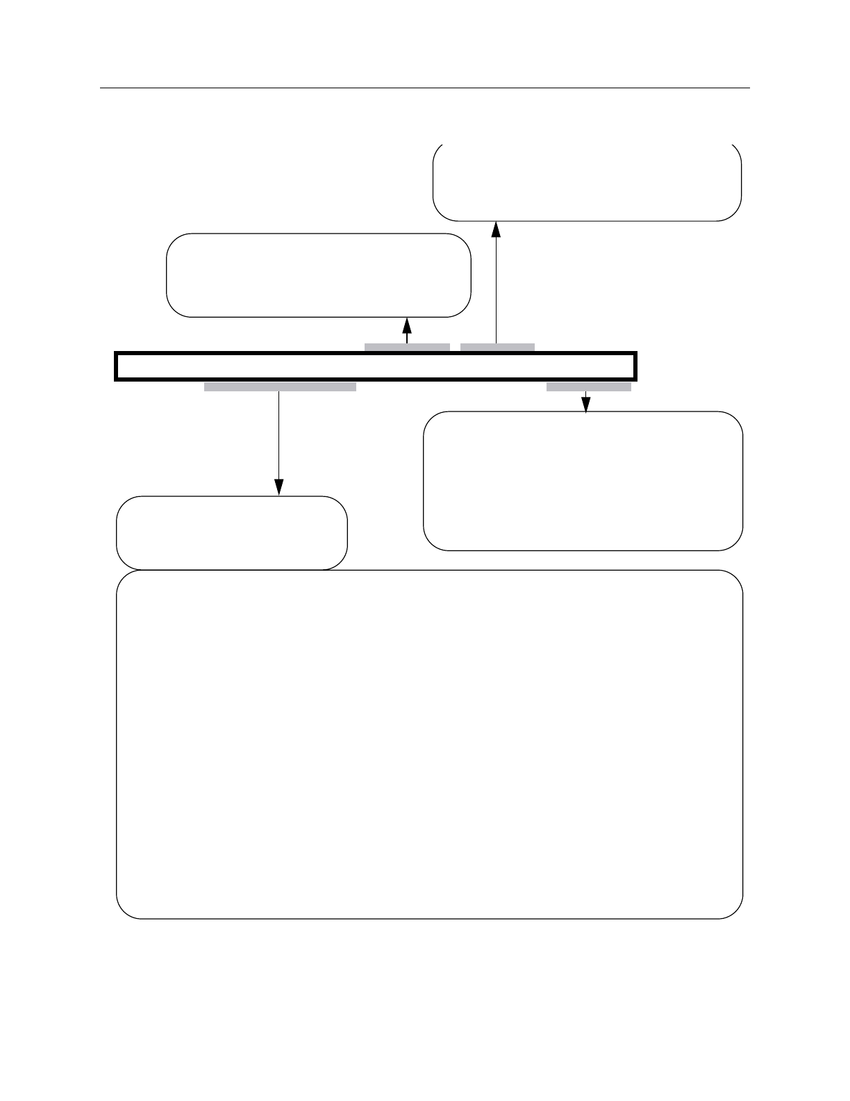
FastScan and FlexTest Reference Manual, V8.6_4
2-316
Report Gates Command Dictionary
The following describes the fields for the write port message line:
write port: write=G/G (vvv-v-v) first_adr=G first_di=G stability=vv
Identifies the behavior of the
write clock and write enable
lines for a given write port:
G/G Two gate index numbers separated by a “/”.
First G is the write clock line.
Second G is the write enable line. A “-”means there is no enable line.
(vvv-v-v) Up to five values indicating the behavior of the following conditions,
respectively:
clock_off_enable_off
clock_on_enable_off (Not shown if there is no enable line.)
clock_off_enable_on (Not shown if there is no enable line.)
two optional clock information values separated by dashes (-)
The first three values can be any of the following:
X (write X)
0 (write 0)
1 (write 1)
H (hold old values)
P (potential write)
The last two values can be either of the following:
CLK (write clock connected to scan clock)
IH (write clock line is inactive high)
Identifies the gate index number of the
first address line for a given write port.
In the list of gate inputs, the other
address inputs will immediately follow.
Identifies the gate index number of the
first data input line for a given write port.
In the list of gate inputs, the other
address inputs will immediately follow.
Identifies the following stability behavior
for a given write port, respectively:
write control stability
write load stability
The values can be either of the following:
S (stable)
U (unstable)
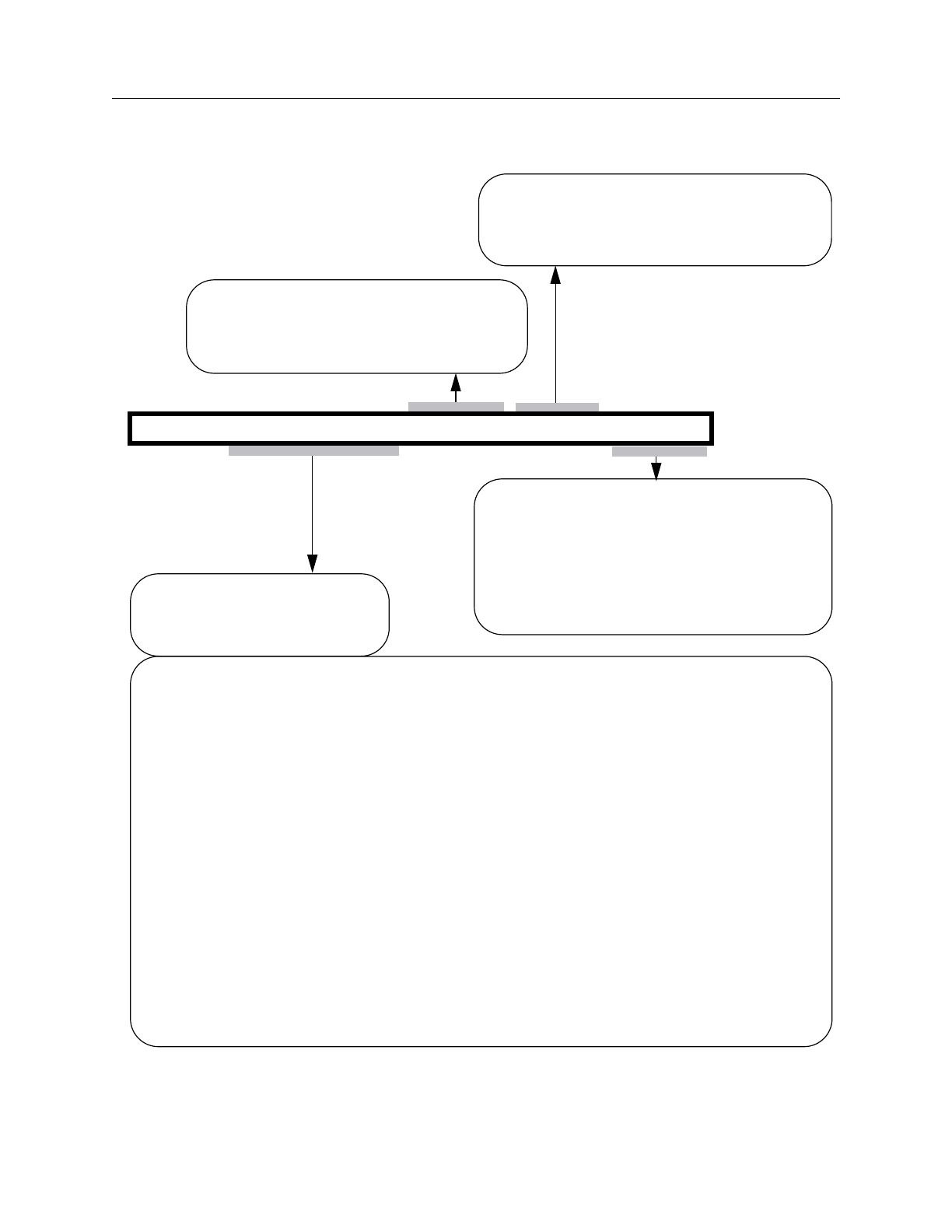
Command Dictionary Report Gates
FastScan and FlexTest Reference Manual, V8.6_4 2-317
The following describes the fields for the read port message line:
read port: read=G/G (vvv-v-v) first_adr=G first_do=G stability=vv
Identifies the behavior of the
read clock and read enable
lines for a given write port:
G/G Two gate index numbers separated by a “/”.
First G is the read clock line.
Second G is the read enable line. A “-”means there is no enable line.
(vvv-v-v) Up to five values indicating the behavior of the following conditions,
respectively:
clock_off_enable_off
clock_on_enable_off (Not shown if there is no enable line.)
clock_off_enable_on (Not shown if there is no enable line.)
two optional clock information values separated by dashes (-)
The first three values can be any of the following:
X (read X)
0 (read 0)
1 (read 1)
H (hold old values)
P (potential read)
The last two values can be either of the following:
CLK (read clock connected to scan clock)
IH (read clock line is inactive high)
Identifies the gate index number of the
first address line for a given read port.
In the list of gate inputs, the other
address inputs will immediately follow.
Identifies the gate index number of the
first data output line for a given read port.
In the list of gate inputs, the other
address inputs will immediately follow.
Identifies the following stability behavior
for a given read port, respectively:
read control stability
read load stability
The values can be either of the following:
S (stable)
U (unstable)

FastScan and FlexTest Reference Manual, V8.6_4
2-318
Report Gates Command Dictionary
The following describes the fields for the Test behavior message line:
Test behavior: Stability=vvvv tiex_flag=v read_only_flag=v ramseq_flags=v/v(vv)
Identifies whether FastScan treats the
RAM as a tieX gate. The possible
values are:
Identifies whether FastScan can test the
RAM in read_only mode. The possible
Identifies the following stability behavior
for a given RAM, respectively:
write control stability
write load stability
The possible values are:
S (stable)
U (unstable)
read control stability
read load stability
0 (no)
1 (yes)
values are:
0 (no)
1 (yes)
Identifies the FastScan ram_sequential
capabilities for a given RAM:
test the RAM in ram_sequential mode
use held output values in a separate pre-load.
The values can be either of the following:
0 (no)
1 (yes)
RAM write values are unstable during seq_transparent procedures.
RAM read values are unstable during seq_transparent procedures.
v/v that identifies whether FastScan
can exercise either of the following
(vv) Two values indicating the stability behavior for a given RAM
during seq_transparent procedures, respectively:
ram_sequential capabilities:
Two values separated by a “/”
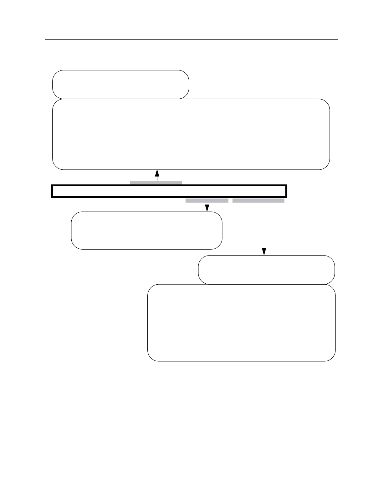
Command Dictionary Report Gates
FastScan and FlexTest Reference Manual, V8.6_4 2-319
The following describes the fields for the Contention Behavior message line:
Arguments
The following lists the three methods for naming the objects on which you want
the tool to display gate information. You can use any number of the three
argument choices, in any order.
Contention Behavior: write_write=v/v read_read=v read_write=v/v
Identifies the behavior when multiple reads
Identifies the contention behavior for a
given RAM when multiple writes are
active, respectively:
The first value specifies how to handle patterns with multiple active write lines.
allow (allow patterns with multiple write lines on)
reject (reject patterns with multiple write lines on)
The second value specifies what FastScan simulates when a simultaneous
X (simulate X)
overwrite (simulate the value from last write)
The possible values are:
write of different values to the same address occurs. The possible values are:
are active. The possible values are:
normal (allow all read values)
X (set read values to X)
Identifies the behavior for a given RAM
with active read and write lines,
respectively:
The first value specifies the read behavior. The
read_new (read newly written values)
read_old (read original values before writing)
The second value specifies the write behavior. The
write_normal (perform normal write operation)
write_X (set write values to X)
possible values are:
possible values are:
read_X (set read values to X)

FastScan and FlexTest Reference Manual, V8.6_4
2-320
Report Gates Command Dictionary
•gate_id# — A repeatable integer that specifies the gate identification numbers
of the objects. The value of the gate_id# argument is the unique identification
number that the tool automatically assigns to every gate within the design
during the model flattening process.
•pin_pathname — A repeatable string that specifies the names of pins within
the design.
•instance_name — A repeatable string that specifies the top-level boundary
instance names within the design. This is used for the design level only.
•-Type gate_type
A repeatable switch where gate_type is a name pair that specifies the gate
types for which you want to display the gate information. Table 2-3 lists the
supported types for each tool. Tables 2-4 and 2-5 list the valid FlexTest learned
types and the valid FastScan clock port categories, respectively.
FastScan Only - The ALLF option allows you to report gates on all primitive
level gates and ATPG functions. This feature supports users who require
access to FastScan flattened models.
•-Forward {pin_pathname | gate_id}...
An optional switch that reports the fan-out cone of the specified gate.
•-Backward {pin_pathname | gate_id}...
An optional switch that reports the fan-in cone of the specified gate.
•-Endpoints [-Forward | -Backward] {pin_pathname | gate_id}...
An optional switch that reports only the endpoint of the cone.
•-COnstraint [-Forward | -Backward] {pin_pathname | gate_id}...
An optional switch that takes into account the effects of pin and cell
constraints.
Note
Immediately after -Endpoints, you must specify either -Forward or
-Backward followed by the specified gate. When using -Endpoints
or -COnstraint simultaneously, -Forward or -Backward followed
by the specified gate need only be entered once.

Command Dictionary Report Gates
FastScan and FlexTest Reference Manual, V8.6_4 2-321
For a gate whose output is constrained to a fixed value, the tool reports only
other gates whose output is also constrained. For a gate whose output is not
constrained to a fixed value, the tools reports only other gates whose outputs
are not constrained. During backwards tracing, a mux input, which is always
blocked by a constrained value on the select line of the mux, will never be back
traced.
•-Path {gate_id# | pin_pathname} {gate_id# | pin_pathname} (FastScan Only)
An optional switch that reports on the path between the first gate_id# |
pin_pathname and the second gate_id# | pin_pathname. All paths must be
specified at the primitive level. Paths do not extend through sequential
elements. The output generates a report on each primitive in the path(s), in
order of increasing gate_id#.
•-Depth (FlexTest Only)
An optional switch that extends the cone report to several levels. The next
level cones reported will be the cones of the endpoints of the previous level. If
there are loops in a circuit, gates may be repeated in several levels. The default
is only one level.
Note
Immediately after -Constraint, you must specify either -Forward or
-Backward followed by the specified gate. When using -Endpoints
or -COnstraint simultaneously, -Forward or -Backward followed
by the specified gate need only be entered once.
Table 2-3. Reportable Gate Types
gate_type
FastScan FlexTest Description
BUF BUF buffer
INV INV inverter
AND AND and
NAND NAND inverted and
OR OR or
NOR NOR inverted or

FastScan and FlexTest Reference Manual, V8.6_4
2-322
Report Gates Command Dictionary
XOR XOR exclusive-or
NXOR NXOR inverted exclusive-or
DFF DFF D flip-flop, same as _dff library
primitive
LA DLAT latch, same as _dlat library primitive
PI PI primary input
PO PO primary output
TIE0 TIE0 tied low
TIE1 TIE1 tied high
TIEX TIEX tied unknown
TIEZ TIEZ tied high impedence
HIST histogram of each primitive type
used
TSD TSH tri-state driver,
first input is active high enable line
for FastScan,
and second input is active high
enable line for FlexTest
BUS BUS tri-state bus
ZVAL Z2X Z converter gate, converts Z to X
WIRE WIRE undetermined wired gate
MUX MUX 2-way multiplexor,
first line is select line (FastScan)
Third line is select line (FlexTest)
Table 2-3. Reportable Gate Types [continued]
gate_type
FastScan FlexTest Description

Command Dictionary Report Gates
FastScan and FlexTest Reference Manual, V8.6_4 2-323
SW NMOS switch gate,
first input is active high enable line
for FastScan,
and second input is active high
enable line for FlexTest
PBUS SWBUS pulled bus gate,
where the second input is the pulled
value
OUT ROUT memory model gate,
created for each read data bit
RAM RAM random access memory
ROM ROM read only memory
XDET XDET X detector, gives 1 when input is X
ZDET ZDET Z detector, gives 1 when input is Z
TLA transparent latch
STLA seq_transparent latch
STFF seq_transparent flip-flip
Table 2-4. FlexTest Learned Gate Types
LEARN_BUF LEARN_XOR LEARN_TIED_Or
LEARN_INV LEARN_MUX FORBid
LEARN_AND LEARN_TIED_Xor ZHOLD
LEARN_OR LEARN_TIED_And
Table 2-3. Reportable Gate Types [continued]
gate_type
FastScan FlexTest Description

FastScan and FlexTest Reference Manual, V8.6_4
2-324
Report Gates Command Dictionary
For more information on using the clock port options, refer to “The ATPG
Analysis Option” of the Design-for-Test: Common Resources Manual.
Examples
The following example displays the simulated values of the gate and its inputs at
the primitive level:
set system mode atpg
set gate report error_pattern
set gate level primitive
report gates i_1006/o
The gate report for the design level may look like the following:
/P2.13P ND2
A I /LD.1
B I /M1.1
Z O /P2.2P/S
The gate report for the primitive level may look like the following:
/P2.13P (23) NAND
A I 9-/LD.1
B I 6-/M1.1
Z O 33-/P2.2P/S
For FastScan the gate report for the primitive level of a RAM gate may look like
the following:
// /P1.RAM/U1 (67) RAM
// "I0" I 27-
// "I1" I 20-
// RCK0 I 36-
// "I3" I 26-
Table 2-5. FastScan Clock Port Categories
Category Description
IL inactive low
IH inactive high
AHS active high slave
ALS active low slave

Command Dictionary Report Gates
FastScan and FlexTest Reference Manual, V8.6_4 2-325
// "I4" I 42-
// "I5" I 43-
// "I6" I 44-
// "I7" I 45-
// "I8" I 46-
// WCK0 I 28-
// "I10" I 19-
// A14 I 29-
// A13 I 30-
// A12 I 31-
// A11 I 32-
// A10 I 34-
// D14 I 66-/P1.RAM/D1[0]
// D13 I 65-/P1.RAM/D1[1]
// D12 I 64-/P1.RAM/D1[2]
// D11 I 63-/P1.RAM/D1[3]
// D10 I 62-/P1.RAM/D1[4]
// "OUT" O 68- 69- 70-
// 71- 72-
// address size = 5
// data size = 5
// minimum address = 0
// maximum address = 31
// number write ports = 1
// number read ports = 1
// edge_triggered = no
// initialization file = ram.init_file
// write port: write=28/- (H) first_adr=29 first_di=66
stability=SS
// read port: read=36/- (0) first_adr=42 first_do=68
stability=SS
// Test behavior: stability=SSSS tiex_flag=0
read_only_flag=1 ramseq_flags=1/0(00)
// Contention behavior: write_write=allow/X
read_read=normal read_write=read_new/write_normal
Related Commands
Set Gate Level Set Gate Report

FastScan and FlexTest Reference Manual, V8.6_4
2-326
Report Hosts Command Dictionary
Report Hosts
Tools Supported: FlexTest
Scope: Only valid when using Distributed FlexTest
Usage
REPort Hosts
Description
Displays information on the hosts available for distributed processing.
The Report Hosts command lists the various attributes of the remote machines
configured for parallel processing, including the working directories,
MGC_HOME path names, the number of tasks scheduled, the relative speeds and
the platform types. This information reflects information in the Host File that is
specified at invocation when using Distributed FlexTest.
For more information on distributed processing, see “Distributed FlexTest” on
page 5-1.
Examples
report hosts

Command Dictionary Report Id Stamp
FastScan and FlexTest Reference Manual, V8.6_4 2-327
Report Id Stamp
Tools Supported: FastScan
Scope: Atpg, Good, and Fault modes
Usage
REPort ID Stamp
Description
Displays the unique identifier that FastScan assigns each internal pattern set.
The Report Id Stamp command displays the current internal pattern set’s unique
identification stamp which consists of five fields, each separated by a colon (:).
Due to the length of three of the fields, FastScan encodes those fields and displays
the encoded information. FastScan encodes the three fields using four bytes of
hexadecimal numbers. This encoding’s primary use is to ensure that each pattern
set has a unique identification stamp. The following list shows the information
each field provides:
1. FastScan version number
2. Encoded environment settings
3. Encoded DRC rules data
4. Number of patterns in the internal pattern set
5. Encoded pattern data
FastScan generates the identification stamp each time you issue either the Report
Id Stamp command or the Save Patterns -Environment command. You can use the
identification stamp to tag identical patterns saved in different formats.
Examples
The following example displays the unique identification stamp for the current
pattern set:
report id stamp
v8.4_2.18:5c95:3e10:16:1bf2


Command Dictionary Report Iddq Constraints
FastScan and FlexTest Reference Manual, V8.6_4 2-329
Report Iddq Constraints
Tools Supported: FastScan and FlexTest
Scope: Setup mode
Usage
REPort IDdq Constraints [pinname... [-Model modelname]]
Description
Displays the current IDDQ constraints for the specified pins.
The Report Iddq Constraints command displays the IDDQ constraints information
added using the Add Iddq Constraints command.
Arguments
•pinname
An optional repeatable string that specifies the pin pathnames whose IDDQ
constraints you want to display. If you do not specify a pinname, the command
displays the information on all the IDDQ constraints.
•-Model modelname
An optional switch and string pair that specifies the name of a DFT library
model for which the tool reports the IDDQ constraints for all occurrences of
pinname.
Examples
The following example adds two IDDQ pin constraints and then displays the
information on all the IDDQ pin constraints:
set fault type iddq
add iddq constraints c0 /mx1/or1/n2/en
add iddq constraints c1 /mx1/or1/n1/o
report iddq constraints
C0 /MX1/OR1/N2/EN
C1 /MX1/OR1/N1/O


Command Dictionary Report Initial States
FastScan and FlexTest Reference Manual, V8.6_4 2-331
Report Initial States
Tools Supported: FlexTest
Scope: All modes
Usage
REPort INitial States [-All | instance_name...]
Description
Displays the initial state settings of the specified design instances.
The Report Initial States command displays different information regarding the
initialization settings depending on the mode from which you issue the command.
If FlexTest is in the Setup mode, the command displays the initialization settings
that you created by using the Add Initial States command. If FlexTest is in any
other mode, the command displays all the initial state settings (including those in
any test_setup procedures).
Arguments
•-All
An optional switch that displays the initialization settings for all design
hierarchical instances. This is the default.
•instance_name
An optional repeatable string that specifies the names of the design
hierarchical instances for which you want to display the initialization settings.
Examples
The following example assumes you are not in Setup mode and displays all the
current initial settings:
add initial states 0 /amm/g30/ff0
set system mode atpg
report initial states
0 /amm/g30/ff0


Command Dictionary Report LFSR Connections
FastScan and FlexTest Reference Manual, V8.6_4 2-333
Report LFSR Connections
Tools Supported: FastScan
Scope: All modes
Usage
REPort LFsr Connections
Description
Displays a list of all the connections between Linear Feedback Shift Registers
(LFSRs) and primary pins.
The Report LFSR Connections command displays all of the connections between
the LFSRs and the primary pins. These connections were specified with the Add
LFSR Connections commands.
You use this command primarily when simulating Built-In Self Test (BIST)
circuitry.
Examples
The following example displays the connections between the LFSRs and primary
pins:
add lfsrs lfsr1 prpg 5 15 -serial -in
add lfsrs lfsr2 prpg 5 13 -serial -in
add lfsrs misr1 misr 5 11 -parallel -in
add lfsr taps lfsr1 1 3
add lfsr taps lfsr2 2 3
add lfsr connections scan_in.1 lfsr1 3
add lfsr connections scan_out.0 misr1 2
report lfsr connections
Related Commands
Add LFSR Connections Delete LFSR Connections

FastScan and FlexTest Reference Manual, V8.6_4
2-334
Report LFSRs Command Dictionary
Report LFSRs
Tools Supported: FastScan
Scope: All modes
Usage
REPort LFsrs
Description
Displays a list of definitions for all the current Linear Feedback Shift Registers
(LFSRs).
The Report LFSRs command displays all of the LFSRs with their current values
and tap positions, which you specified using the Add LFSRs and Add LFSR Taps
commands.
You use this command primarily when simulating Built-In Self Test (BIST)
circuitry.
Examples
The following example displays the definitions of all the current LFSRs:
add lfsrs lfsr1 prpg 5 15 -serial -in
add lfsrs lfsr2 prpg 5 13 -serial -in
add lfsrs misr1 misr 5 11 -parallel -in
report lfsrs
Related Commands
Add LFSRs
Add LFSR Taps Delete LFSRs
Setup LFSRs

Command Dictionary Report Lists
FastScan and FlexTest Reference Manual, V8.6_4 2-335
Report Lists
Tools Supported: FastScan and FlexTest
Scope: All modes
Usage
REPort LIsts
Description
Displays a list of pins which the tool reports on while in the Fault or Good
simulation system mode.
The Report Lists command displays all of the pins for which the tool creates a
report during simulation. You can use the Add Lists command to put additional
pins on the list. If you wish to view the logic values of the pins in the report, you
must view the list file specified by the Set List File command.
When switching to Setup mode, the tool discards all pins from the report list.
Examples
The following example displays all the pins for which the tool will report
simulation values:
set system mode good
add lists i_1006/o i_1007/o
report lists
2 pins are currently monitored
i_1006/o
i_1007/o
Related Commands
Add Lists
Delete Lists Set List File

FastScan and FlexTest Reference Manual, V8.6_4
2-336
Report Loops Command Dictionary
Report Loops
Tools Supported: FastScan and FlexTest
Scope: Atpg, Fault, and Good modes
Usage
REPort LOops
Description
Displays a list of all the current loops.
The Report Loops command displays all the loops in the circuit. For each loop,
the report indicates whether the loop was broken by duplication. The report shows
loops unbroken by duplication to be broken instead by a constant value, which
means the loop is either a coupling loop or has a single multiple-fanout gate. The
report also includes the pin pathname and gate type of each gate in each loop.
You can write the loops report information to a file by using the Write Loops
command.
Examples
The following example displays a list of all the loops in the circuit:
set system mode atpg
report loops
Related Commands
Write Loops

Command Dictionary Report Mos Direction
FastScan and FlexTest Reference Manual, V8.6_4 2-337
Report Mos Direction
Tools Supported: FastScan and FlexTest
Scope: Setup mode
Prerequisites: This command can only operate on a Spice design.
Usage
REPort MOs Direction [-Unidirection | -Bidirection | -All]
Description
Reports the direction MOS instances in the Spice design and Spice SUBCKT
library.
The Report Mos Direction command reports the direction of all or specified MOS
instances in the Spice design and library. By default, only the bi-directional MOS
instances are reported.
Arguments
•-Unidirection
An optional switch that specifies to list all MOS instances that have a defined
direction.
•-Bidirection
An optional switch that specifies to list all MOS instances that have a no
defined direction (bi-directional). This is the default.
•-All
An optional switch that specifies to list all directional and bi-directional MOS
instances.
Examples
The following example reports all bi-direction MOS instances:
report mos bidirection

FastScan and FlexTest Reference Manual, V8.6_4
2-338
Report Net Properties Command Dictionary
Report Net Properties
Tools Supported: FastScan and FlexTest
Scope: Setup mode
Prerequisites: This command can only operate on a Spice design.
Usage
REPort NEt Properties {-VDD | -GND | -All}
Description
Reports the VDD or GND net properties in the Spice design and library.
The Report Net Properties command reports all Spice VDD or GND net
properties in the Spice design and Spice library. You can also specify to report all
of the VDD and GND nets at one time using the -All option.
Arguments
•-VDD | -GND | -All
A required switch that specifies whether to report VDD or GND net properties.
You can also specify to report on both using the -All switch.
Examples
The following example reports all GND nets:
report net properties -gnd
Related Commands
Add Net Property Delete Net Property

Command Dictionary Report Nofaults
FastScan and FlexTest Reference Manual, V8.6_4 2-339
Report Nofaults
Tools Supported: FastScan and FlexTest
Scope: All modes
Usage
REPort NOfaults pathname... | -All [-Instance] [-Stuck_at {01 | 0 | 1}] [-Class
{Full | User | System}]
Description
Displays the nofault settings for the specified pin pathnames or pin names of
instances.
The Report Nofaults command displays for pin pathnames or pin names of
instances the nofault settings which you previously specified with the Add
Nofaults command.
Arguments
•pathname
A repeatable string that specifies the pin pathnames or the instance pathnames
for which you want to display the nofault settings. If you specify an instance
pathname, you must also specify the -Instance switch.
•-All
A switch that displays the nofault settings on either all pin pathnames or, if you
also specify the -Instance switch, all pin names of instances.
•-Instance
An optional switch that specifies that the pathname or -All argument indicates
instance pathnames.
•-Stuck_at 01 | 0 | 1
An optional switch and literal pair that specifies the stuck-at nofault settings
which you want to display. The stuck-at literal choices are as follows:
01 — A literal that displays both the “stuck-at-0” and “stuck-at-1” nofault
settings. This is the default.

FastScan and FlexTest Reference Manual, V8.6_4
2-340
Report Nofaults Command Dictionary
0 — A literal that displays only the “stuck-at-0” nofault settings.
1 — A literal that displays only the “stuck-at-1” nofault settings.
•-Class Full | User | System
An optional switch and literal pair that specifies the source (or class) of the
nofault settings which you want to display. The literal choices are as follows:
Full — A literal that displays all the nofault settings in the user and system
class. This is the default.
User — A literal that displays only the user-entered nofault settings.
System — A literal that displays only the netlist-described nofault settings.
Examples
The following example displays all pin names of the instances that have the
nofault settings:
add nofaults i_1006 i_1007 i_1008 -instance
report nofaults
Related Commands
Add Nofaults Delete Nofaults

Command Dictionary Report Nonscan Cells
FastScan and FlexTest Reference Manual, V8.6_4 2-341
Report Nonscan Cells
Tools Supported: FastScan and FlexTest
Scope: Atpg, Fault, and Good modes
Usage
For FastScan
REPort NOnscan Cells [-All | -TIE0 | -TIE1 | -TIEX | -TLatch | -Clock_sequential
| -INIT0 | -INIT1]
For FlexTest
REPort NOnscan Cells [-All | -INITX | -TIE0 | -TIE1 | -Hold | -Data_capture]
Description
Displays the non-scan cells whose model type you specify.
The Report Nonscan Cells command displays the instance name, gate number,
and model type of the non-scan cells that you specify. The tool assigns a model
type to the non-scan cells during the Design Rules Check (DRC) in order to model
non-scan memory behavior more exactly.
During scan loading, scan clocks can affect non-scan memory elements. The
worst case is to assume that all non-scan memory elements will have an unknown
state right after scan loading, which makes some faults difficult to test. Therefore,
the tool assigns an appropriate model type to the non-scan cells, which sets them
to known values. The argument descriptions that follow describe the conditions
that the tool uses to make the various model type assignments.
Arguments
•-All
An optional switch that displays all non-scan cells. This is the default.
•-INITX (FlexTest Only)
An optional switch that displays the non-scan cells which FlexTest initializes
to X after each loading.

FastScan and FlexTest Reference Manual, V8.6_4
2-342
Report Nonscan Cells Command Dictionary
•-TIE0
An optional switch that displays the non-scan cells which are always 0 after
each loading and before the next unloading.
Non-scan cells that the tool models as TIE0 indicate that the pin constraints
hold the cell’s value during non-scan operation.
•-TIE1
An optional switch that displays the non-scan cells which are always 1 after
each loading and before the next unloading.
Non-scan cells that the tool models as TIE1 indicate that the pin constraints
hold the cell’s value during non-scan operation.
•-TIEX (FastScan Only)
An optional switch that displays the non-scan cells which are always unknown
(X) after each loading and before the next unloading.
•-TLatch (FastScan Only)
An optional switch that displays the non-scan cells which FastScan models as
transparent latches.
•-Clock_sequential (FastScan Only)
An optional switch that displays all clock_sequential cells that are valid when
the sequential depth is set to non-zero.
•-INIT0 (FastScan Only)
An optional switch that displays a list of cells which DRC has identified as
being initialized to 0 by scan load but has failed to prove that it is tied to 0.
Non-scan cells that the tool models as INIT0 indicate one of the following:
oThe test procedure can set the memory element to 0 after scan loading.
oThe non-off clock is a reset.
•-INIT1 (FastScan Only)
An optional switch that displays a list of cells which DRC has identified as
being initialized to 1 by scan load but has failed to prove that it is tied to 1.

Command Dictionary Report Nonscan Cells
FastScan and FlexTest Reference Manual, V8.6_4 2-343
Non-scan cells that the tool models as INIT1 indicate one of the following:
oThe test procedure can set the memory element to 1 after scan loading.
oThe non-off clock is a set.
•-Hold (FlexTest Only)
An optional switch that displays the non-scan cells that hold their value during
each loading, when all scan capture clocks are off.
Non-scan cells that FlexTest models as Clock Hold indicate that, during the
scan loading, all scan capture clocks of the non-scan cell are off.
•-Data_capture (FlexTest Only)
An optional switch that displays the non-scan cells that hold their data value
during each loading, when all scan capture clocks but one are off.
Non-scan cells that FlexTest models as Data Hold indicate that, during the
scan loading, all but one of the scan capture clocks of the non-scan cell are off,
that one clock is active at least once, and that its corresponding data input does
not change during scan loading.
Examples
FastScan Example
The following FastScan example displays only the non-scan cells that FastScan
models as transparent latches.
add scan groups g1 proc.g1
add scan chains c1 g1 scin scout
add clocks 0 clk
set system mode atpg
report nonscan cells -tlatch
add faults -all
run

FastScan and FlexTest Reference Manual, V8.6_4
2-344
Report Nonscan Cells Command Dictionary
FlexTest Example
The following FlexTest example displays only the non-scan cells that FlexTest
initializes to X after each loading.
add scan groups g1 proc.g1
add scan chains c1 g1 scin scout
add clocks 0 clk
set system mode atpg
report nonscan cells -initx
add faults -all
run

Command Dictionary Report Nonscan Handling
FastScan and FlexTest Reference Manual, V8.6_4 2-345
Report Nonscan Handling
Tools Supported: FlexTest
Scope: All modes
Usage
REPort NOnscan Handling [element_pathname... | -All]
Description
Displays the overriding learned behavior classification for the specified non-scan
elements.
The Report Nonscan Handling command displays the learned behavior
classification you created using the Add Nonscan Handling command.
Arguments
•element_pathname
A repeatable string that specifies the pathname to the non-scan element for
which you want to display the current user-defined learned behavior
classification.
•-All
A switch that displays the user-defined learned behavior classifications for all
non-scan elements. This is the default.
Examples
The following example explicitly defines how you want FlexTest to handle two
non-scan elements, and then reports on the current list of learned behavior
overrides for the design rules checker:
add nonscan handling tie0 i_6_16 i_28_3
report nonscan handling
TIE0 I_6_16
TIE0 I_28_3
Related Commands
Add Nonscan Handling Delete Nonscan Handling

FastScan and FlexTest Reference Manual, V8.6_4
2-346
Report Notest Points Command Dictionary
Report Notest Points
Tools Supported: FastScan
Scope: Atpg, Fault, and Good modes
Usage
REPort Notest Points
Description
Displays all the circuit points for which you do not want FastScan to insert
controllability and observability.
The Report Notest Points command displays the circuit points added using the
Add Notest Points command and which therefore, FastScan cannot use for
testability insertion.
You use this command primarily when simulating Built-In Self Test (BIST)
circuitry.
Examples
The following example displays the list of all circuit points that FastScan cannot
use for testability insertion:
set system mode fault
add notest points i_1006/o i_1007/o
add notest points i_1009/o
report notest points
insert testability
Related Commands
Add Notest Points Delete Notest Points

Command Dictionary Report Observe Data
FastScan and FlexTest Reference Manual, V8.6_4 2-347
Report Observe Data
Tools Supported: FastScan
Scope: Atpg, Good, and Fault modes
Prerequisites: You must use the Analyze Observe command prior to this
command.
Usage
REPort OBserve Data [filename] [-Replace]
Description
Displays information from the preceding Analyze Observe command.
The Report Observe Data command displays a summary of the information that
FastScan obtained from the preceding Analyze Observe command.
When the Analyze Observe command fails to detect an output pin for a minimum
number of the random patterns (as defined by the observe threshold), FastScan
identifies the output pin as inadequately observed. For each inadequately-
observed output pin the Analyze Observe command searches for the potential
source of the pin’s observe problem. This it calculates by tracing forward from the
pin through the most difficult-to-observe fanout gate until it reaches a gate which
has no fanout and an observability value less than the threshold.
The Report Observe Data command’s summary report lists up to a maximum of
25 source gates, which, if made observable, would affect a maximum number of
other gates. The command orders the list of gates by the low-observability gates
and includes the low-observability pins, the number of times observed, and the
calculated source gate.
You can write the summary report to a file by specifying a filename.
You use this command primarily when simulating Built-In Self Test (BIST)
circuitry.

FastScan and FlexTest Reference Manual, V8.6_4
2-348
Report Observe Data Command Dictionary
Arguments
•filename
An optional string that specifies the filename to which you want to write the
summary report. If you do not specify a filename, the command displays the
information on the screen.
•-Replace
An optional switch that replaces the contents of the file, if one by the same
name already exists.
Examples
The following example displays detailed information obtained from using the
Analyze Observe command:
set system mode fault
add observe points i_1006/o i_1007/o
set random patterns 612
set observe threshold 2
analyze observe
report observe data
Related Commands
Add Observe Points
Analyze Observe Set Observe Threshold
Set Random Patterns

Command Dictionary Report Observe Points
FastScan and FlexTest Reference Manual, V8.6_4 2-349
Report Observe Points
Tools Supported: FastScan
Scope: Atpg, Fault, and Good modes
Usage
REPort OBserve Points
Description
Displays a list of all the current observe points.
The Report Observe Points command displays a list of all the observe points
added with the Add Observe Points command.
You use this command primarily when simulating Built-In Self Test (BIST)
circuitry.
Examples
The following example displays the list of all added observe points:
set system mode fault
add observe points i_1006/o i_1007/o
add observe points i_1009/o
report observe points
Related Commands
Add Observe Points
Analyze Observe Delete Observe Points
Report Observe Data

FastScan and FlexTest Reference Manual, V8.6_4
2-350
Report Output Masks Command Dictionary
Report Output Masks
Tools Supported: FastScan and FlexTest
Scope: All modes
Usage
REPort OUtput Masks
Description
Displays a list of the currently masked primary output pins.
The Report Output Masks command displays the primary output pins masked
using the Add Output Masks command. When you mask a primary output pin, the
tool marks that pin as an invalid observation point during the fault detection
process. The tool uses all unmasked primary output pins as possible observation
points to which the effects of all faults propagate for detection.
Examples
The following example masks two primary outputs and then displays the results:
add output masks qb1 qb2
report output masks
qb1
qb2
Related Commands
Add Output Masks Delete Output Masks

Command Dictionary Report Paths
FastScan and FlexTest Reference Manual, V8.6_4 2-351
Report Paths
Tools Supported: FastScan
Scope: Atpg, Good, and Fault modes
Usage
REPort PAths [-All | path_name] [-Path gate_id_begin gate_id_end]
Description
Displays the path definitions of the specified loaded paths.
The Report Paths command displays the internal path list definitions for the paths
that you specify. You load the path definitions into the internal path list by using
the Load Paths command.
Arguments
•-All
An optional switch that displays the definitions for all currently loaded paths.
This is the default.
•path_name
An optional string that specifies the name of the path whose definition you
want to display. You define the paths in a path definition file which you must
have previously loaded by using the Load Paths command.
•-Path gate_id_begin gate_id_end
An optional switch and two integer triplet that specifies a particular path or
portion of a path whose definition you want to display. You use this argument
to report on paths that were not defined in a path definition file and therefore
were not loaded using the Load Paths command.
The two integer arguments specify two gate identification numbers that
indicate the beginning and ending of the path. The path begins at
gate_id_begin and ends with gate_id_end.
The value of the gate_id_begin and gate_id_end arguments is the unique
identification number that FastScan automatically assigns to every gate within
the design during the model flattening process.

FastScan and FlexTest Reference Manual, V8.6_4
2-352
Report Paths Command Dictionary
Examples
The following example reads in (loads) the path information and then displays
that data:
set fault type path_delay
load paths /user/design/pathfile
report paths
PATH “path0” =
PIN /I$6/Q + ;
PIN /I$35/B0 + ;
PIN /I$35/C0 + ;
PIN /I$1/I$650/IN + ;
PIN /I$1/I$650/OUT - ;
PIN /A_EQ_B + ;
END ;
PATH “path1” =
PIN /I$6/Q + ;
PIN /I$35/B1 + ;
PIN /I$35/C1 + ;
PIN /I$1/I$649/IN + ;
PIN /I$1/I$649/OUT - ;
PIN /I$5/D - ;
END ;
Related Commands
Add Display Path
Delete Paths
Load Paths
Set Fault Type
Write Paths

Command Dictionary Report Pin Constraints
FastScan and FlexTest Reference Manual, V8.6_4 2-353
Report Pin Constraints
Tools Supported: FastScan and FlexTest
Scope: All modes
Usage
For FastScan
REPort PIn Constraints
For FlexTest
REPort PIn Constraints [-All | primary_input_pin...]
Description
Displays the pin constraints of the primary inputs.
The Report Pin Constraints command displays the pin constraints added to the
primary inputs with the Add Pin Constraints command.
The Report Pin Constraints command, as does the Add Pin Constraints command,
performs slightly differently depending on whether you are using FastScan or
FlexTest. The following paragraphs described how the command operates for
each tool.
FastScan Specifics
The command displays the constraints on all the primary inputs which you
restricted to be at a constant value during the ATPG process.
FlexTest Specifics
The command displays the cycle behavior constraints of the specified primary
inputs. If you do not specify any primary input pins, the command displays the
constraints of all the primary inputs. You can change the cycle behavior
constraints of the primary inputs by using either the Add Pin Constraints or Setup
Pin Constraints commands.

FastScan and FlexTest Reference Manual, V8.6_4
2-354
Report Pin Constraints Command Dictionary
Arguments
•-All (FlexTest Only)
An optional switch that displays the current constraints for all primary input
pins. This is the default.
•primary_input_pin (FlexTest Only)
An optional repeatable string that specifies a list of primary input pins whose
constraints you want to display.
Examples
FastScan Example
The following FastScan example displays the constraints of all primary inputs:
add pin constraints indata2 c1
add pin constraints indata4 c0
report pin constraints
FlexTest Example
The following FlexTest example displays the cycle behavior constraints of all
primary inputs:
set test cycle 2
add pin constraints ph1 R1 1 0 1
add pin constraints ph2 R0 1 0 1
report pin constraints -all
Related Commands
Add Pin Constraints
Delete Pin Constraints Setup Pin Constraints (FT)

Command Dictionary Report Pin Equivalences
FastScan and FlexTest Reference Manual, V8.6_4 2-355
Report Pin Equivalences
Tools Supported: FastScan and FlexTest
Scope: All modes
Usage
REPort PIn Equivalences
Description
Displays the pin equivalences of the primary inputs.
The Report Pin Equivalences command displays a list of primary inputs which
you restricted to be at equivalent or complementary values using the Add Pin
Equivalences command.
Examples
The following example displays all pin equivalences added to the primary inputs:
add pin equivalences indata2 indata4
add pin equivalences indata3 -invert indata5
report pin equivalences
Related Commands
Add Pin Equivalences Delete Pin Equivalences

FastScan and FlexTest Reference Manual, V8.6_4
2-356
Report Pin Strobes Command Dictionary
Report Pin Strobes
Tools Supported: FlexTest
Scope: All modes
Usage
REPort PIn Strobes [-All | primary_output_pin...]
Description
Displays the current pin strobe timing for the specified primary output pins.
The Report Pin Strobes command displays the strobe time of each primary output
pin that you specify. If you issue the command without any arguments, FlexTest
displays all of the pin strobes.
Arguments
•-All
An optional switch that displays the pin strobe values for all of the primary
output pins. This is the default.
•primary_output_pin
An optional repeatable string that specifies a list of primary output pins whose
pin strobe timing you want to display.
Examples
The following example displays the strobe times of all primary outputs:
set test cycle 3
add pin strobes 1 outdata1 outdata3
report pin strobes
Related Commands
Add Pin Strobes
Delete Pin Strobes Setup Pin Strobes

Command Dictionary Report Primary Inputs
FastScan and FlexTest Reference Manual, V8.6_4 2-357
Report Primary Inputs
Tools Supported: FastScan and FlexTest
Scope: All modes
Usage
REPort PRimary Inputs [-All | net_pathname... | primary_input_pin...] [-Class
{Full | User | System}]
Description
Displays the specified primary inputs.
The Report Primary Inputs command displays a list of the primary inputs of a
circuit. You can choose to display either the user class, system class, or full
classes of primary inputs. Additionally, you can display all the primary inputs or a
specific list of primary inputs. If you issue the command without specifying any
arguments, then the tool displays all the primary inputs.
Arguments
•-All
An optional switch that displays all the primary inputs. This is the default.
•net_pathname
An optional repeatable string that specifies the circuit connections whose user-
class primary inputs you want to display.
•primary_input_pin
An optional repeatable string that specifies a list of system-class primary input
pins that you want to display.
•-Class Full | User | System
An optional switch and literal pair that specifies the source (or class) of the
primary input pins which you want to display. The literal choices are as
follows:
Full — A literal that displays all the primary input pins in the user and
system class. This is the default.

FastScan and FlexTest Reference Manual, V8.6_4
2-358
Report Primary Inputs Command Dictionary
User — A literal that displays only the user-entered primary input pins.
System — A literal that displays only the netlist-described primary input
pins.
Examples
The following example displays the full classes of primary inputs:
add primary inputs indata2 indata4
report primary inputs -class full
Related Commands
Add Primary Inputs
Delete Primary Inputs Write Primary Inputs (FT)

Command Dictionary Report Primary Outputs
FastScan and FlexTest Reference Manual, V8.6_4 2-359
Report Primary Outputs
Tools Supported: FastScan and FlexTest
Scope: All modes
Usage
REPort PRimary Outputs [-All | net_pathname... | primary_output_pin...] [-Class
{Full | User | System}]
Description
Displays the specified primary outputs.
The Report Primary Outputs command displays a list of primary outputs of a
circuit. You can choose to display either the user class, system class, or full
classes of primary outputs. Additionally, you can display all the primary outputs
or a specific list of primary outputs. If you issue the command without specifying
any arguments, then the tool displays all the primary outputs.
Arguments
•-All
An optional switch that displays all primary outputs. This is the default.
•net_pathname
An optional repeatable string that specifies the circuit connections whose user-
class primary outputs you want to display.
•primary_output_pin
An optional repeatable string that specifies a list of system-class primary
output pins that you want to display.
•-Class Full | User | System
An optional switch and literal pair that specifies the source (or class) of the
primary input pins which you want to display. The literal choices are as
follows:
Full — A literal that displays all the primary input pins in the user and
system class. This is the default.

FastScan and FlexTest Reference Manual, V8.6_4
2-360
Report Primary Outputs Command Dictionary
User — A literal that displays only the user-entered primary input pins.
System — A literal that displays only the netlist-described primary input
pins.
Examples
The following example displays all primary outputs in the user class:
add primary outputs outdata1 outdata3 outdata5
report primary outputs -class user
Related Commands
Add Primary Outputs
Delete Primary Outputs Write Primary Inputs (FT)

Command Dictionary Report Procedure
FastScan and FlexTest Reference Manual, V8.6_4 2-361
Report Procedure
Tools Supported: FastScan and FlexTest
Scope: All modes except Setup mode
Usage
REPort PRocedure {procedure_name [group_name] | -All}
Description
Displays the specified procedure.
The Report Procedure command displays the specified procedure to the screen.
Arguments
•procedure_name
A string that specifies which procedure to display.
•group_name
An optional string that specifies a particular scan group from which to display
the specified procedure.
•-All
A switch that specifies for the tool to display all procedures. This is the default.
Related Commands
Add Scan Groups
Read Procfile
Report Timeplate
Save Patterns
Write Procfile

FastScan and FlexTest Reference Manual, V8.6_4
2-362
Report Pulse Generators Command Dictionary
Report Pulse Generators
Tools Supported: FastScan and FlexTest
Scope: All modes
Usage
REPort PUlse Generators
Description
Displays the list of pulse generator sink (PGS) gates.
The Report Pulse Generators command displays the list of PGS gates that the tool
identifies during the learning process.
You use this command primarily when simulating Built-In Self Test (BIST)
circuitry.
Examples
The following example displays the current list of PGS gates:
set pulse generators on
set system mode atpg
report pulse generators
Related Commands
Set Pulse Generators

Command Dictionary Report Random Weights
FastScan and FlexTest Reference Manual, V8.6_4 2-363
Report Random Weights
Tools Supported: FastScan
Scope: Atpg, Fault, and Good modes
Usage
REPort RAndom Weights
Description
Displays the current random pattern weighting factors for all primary inputs in the
random weight list.
The Report Random Weights command displays the current random weight value
placed on primary inputs using the Add Random Weights command. You can
specify the default weighting factor for all primary inputs by using the Set
Random Weights command but, FastScan does not place the default value in the
random weight list.
You use this command primarily when simulating Built-In Self Test (BIST)
circuitry.
Examples
The following example displays the weighting factors for all the primary inputs in
the random weight list:
set system mode fault
add random weights 100 indata2
add random weights 25 indata4
report random weights
set random patterns 612
insert testability
Related Commands
Add Random Weights
Delete Random Weights Set Random Weights

FastScan and FlexTest Reference Manual, V8.6_4
2-364
Report Read Controls Command Dictionary
Report Read Controls
You Tools Supported: FastScan and FlexTest
Scope: All modes
Usage
REPort REad Controls
Description
Displays all of the currently defined read control lines.
The Report Read Controls command displays all the read control lines specified
using the Add Read Controls command. The display also includes the
corresponding off-state with each read control line.
Examples
The following example displays a list of the current read control lines:
add read controls 0 r1 r3
add read controls 1 r2 r4
report read controls
Related Commands
Add Read Controls Delete Read Controls

Command Dictionary Report Scan Cells
FastScan and FlexTest Reference Manual, V8.6_4 2-365
Report Scan Cells
Tools Supported: FastScan and FlexTest
Scope: Atpg, Fault, and Good modes
Usage
REPort SCan CElls [-All | chain_name...]
Description
Displays a report on the scan cells that reside in the specified scan chains.
The Report Scan Cells command provides a report on the scan cells within
specific scan chains. The report provides the following information for each scan
cell:
•Chain cell index number, where 0 is the scan cell closest to the scan-out pin.
•Scan chain and the scan chain group in which the scan cell resides
•Memory element type
•Inversion data
•Gate index number
•Instance name
•Model name
•Cell input and output pins
If you issue the command without specifying any arguments, then the tool
displays a report on the scan cells for all scan chains.
Note
Although scan cells are listed in the order of nearest-to-output
first, the latch elements inside one cell are not listed in that order
(in fact, the master is always listed first).

FastScan and FlexTest Reference Manual, V8.6_4
2-366
Report Scan Cells Command Dictionary
Arguments
•-All
An optional switch that displays the scan cells for all scan chains. This is the
default.
•chain_name
An optional repeatable string that specifies the scan chains whose scan cells
you want to display.
Examples
The following example displays a list of the scan cells for all the scan chains:
add scan groups group1 scanfile
add scan chains chain1 group1 indata2 outdata4
set system mode atpg
report scan cells
cell# chain group mem_type inv. gate# ins_name (ext.pin name)
-------------------------------------------------------------
0 chain1 group1 MASTER FFFF 7402 /MQ_I400 ““ (TI,QN)
1 chain1 group1 MASTER FFFF 7394 /FH_I400 ““ (TI,QN)
2 chain1 group1 MASTER FFFF 7367 /FQ_I10 ““ (TI,QN)
3 chain1 group1 MASTER FFFF 7366 /RP_I10 ““ (TI,QN)
4 chain1 group1 MASTER FFFF 7365 /IS_I10 ““ (TI,QN)
5 chain1 group1 MASTER FFFF 7386 /CZ_I400 ““ (TI,QN)
The first column in the report displays the chain cell index number, where 0 is the
scan cell closest to the scan-out pin.
The second column displays the name of the scan chain in which the scan cell
resides.
The third column displays the name of the scan group in which the scan chain
resides.
The fourth column displays the scan cell’s type of memory element.
The fifth column contains inversion data using F (false) to indicate no inversion
difference and T (true) to indicate inversion difference. The inversion data has
four elements; one for each scan cell memory element. The report presents the
elements (left-to-right) as follows:

Command Dictionary Report Scan Cells
FastScan and FlexTest Reference Manual, V8.6_4 2-367
1. Inversion of the scan cell input pin, library cell input pin, or scan subchain
relative to the scan chain input pin.
2. Inversion of the scan cell output pin, library cell output pin, or scan
subchain relative to the scan chain output pin.
3. Inversion of the scan cell memory gate relative to the library cell input pin.
4. Inversion of the scan cell memory gate relative to the library cell output
pin.
The sixth column displays the gate index number.
The seventh column displays the instance name of the memory element.
The eighth column displays the library instance name. If there is no library
instance name, then the report shows two double quotes in the library instance
name field.
The last column displays the library cell input and output pins of the scan cell. If
the scan cell input or output pin does not directly connect to the library cell
boundary pin, the report shows a dash (-) in the corresponding pin field.
Related Commands
Add Scan Chains Add Scan Groups

FastScan and FlexTest Reference Manual, V8.6_4
2-368
Report Scan Chains Command Dictionary
Report Scan Chains
Tools Supported: FastScan and FlexTest
Scope: All modes
Usage
REPort SCan CHains
Description
Displays a report on all the current scan chains.
The Report Scan Chains command provides the following information in a report
for each scan chain:
•Name of the scan chain
•Name of the scan chain group
•Scan chain input and output pins
•Length of the scan chain
Examples
The following example displays a report of all the scan chains:
add scan groups group1 scanfile
add scan chains chain1 group1 indata2 outdata4
add scan chains chain2 group1 indata3 outdata5
report scan chains
Related Commands
Add Scan Chains Delete Scan Chains

Command Dictionary Report Scan Groups
FastScan and FlexTest Reference Manual, V8.6_4 2-369
Report Scan Groups
Tools Supported: FastScan and FlexTest
Scope: All modes
Usage
REPort SCan Groups
Description
Displays a report on all the current scan chain groups.
The Report Scan Groups command provides the following information in a report
for each scan chain group:
•Name of the scan chain group
•Number of scan chains within the scan chain group
•Number of shifts
•Name of the test procedure file, which contains the information for
controlling the scan chains in the reported scan chain group
Examples
The following example displays a report of all the scan groups:
add scan groups group1 scanfile
add scan groups group2 scanfile1
report scan groups
Related Commands
Add Scan Groups Delete Scan Groups

FastScan and FlexTest Reference Manual, V8.6_4
2-370
Report Scan Instances Command Dictionary
Report Scan Instances
Tools Supported: FlexTest
Scope: All modes
Usage
REPort SCan Instances [-Class {Full | User | System}]
Description
Displays the currently defined sequential scan instances.
The Report Scan Instances command displays the sequential scan instances which
you added by using the Add Scan Instances command.
Arguments
•-Class Full | User | System
A switch and literal pair that specifies the source (or class) of the sequential
scan instances which you want to display. The literal choices are as follows:
Full — A literal that displays all the scan sequential instances in the user
and system class. This is the default.
User — A literal that displays only user-entered scan sequential instances.
System — A literal that displays only netlist-described scan sequential
instances.
Examples
The following example displays all sequential scan instances from the scan
instance list:
set system mode setup
add scan instances i_1006 i_1007 i_1008
report scan instances -class user
Related Commands
Add Scan Instances Delete Scan Instances

Command Dictionary Report Scan Models
FastScan and FlexTest Reference Manual, V8.6_4 2-371
Report Scan Models
Tools Supported: FlexTest
Scope: All modes
Usage
REPort SCan Models
Description
Displays the sequential scan models currently in the scan model list.
The Report Scan Models command displays sequential models which you
previously added to the scan model list by using the Add Scan Models command.
Examples
The following example displays all the sequential scan models from the scan
model list:
set system mode setup
add scan models d_flip_flop1 d_flip_flop2
report scan models
Related Commands
Add Scan Models Delete Scan Models

FastScan and FlexTest Reference Manual, V8.6_4
2-372
Report Seq_transparent Procedures Command Dictionary
Report Seq_transparent Procedures
Tools Supported: FastScan
Scope: Atpg, Fault, and Good modes
Usage
REPort SEq_transparent Procedures [-All | procedure_name...] [-CElls]
[-Load_disturbs] [-CApture_disturbs]
Description
Displays a list of seq_transparent test procedures along with the associated data
that you specify.
The Report Seq_transparent Procedures command displays a list of the specified
seq_transparent test procedures. You can optionally display data associated with
each seq_transparent test procedure by specifying the appropriate switches which
are described under “Arguments”.
If you do not specify any of the data switches, the command does not provide any
details about the procedures.
Arguments
•-All
An optional switch that displays the associated data for all seq_transparent
procedures. If you do not specify any other argument with the -All switch, the
command simply lists the names of all the currently defined seq_transparent
procedures. This is the default.
•procedure_name
An optional repeatable string that specifies the names of the seq_transparent
procedures whose data you want to display.
•-CElls
An optional switch that displays the seq_transparent cells associated with the
specified procedures. By default, FastScan does not display these cells.

Command Dictionary Report Seq_transparent Procedures
FastScan and FlexTest Reference Manual, V8.6_4 2-373
•-Load_disturbs
An optional switch that displays the scan cells with load disturbs associated
with the specified procedures. By default, FastScan does not display these
cells.
•-CApture_disturbs
An optional switch that displays the scan cells, primary outputs,
seq_transparent cells, and RAMs which had capture disturbs. By default,
FastScan does not display these items.
Examples
The following example displays all the seq_transparent test procedures, along
with the associated scan cells that had load disturbs:
add scan group g1 seqproc.g1
add scan chain c1 g1 si so
add clocks 0 clk
set system mode atpg
report seq_transparent procedures -all -load_disturbs
Related Commands
Report Gates

FastScan and FlexTest Reference Manual, V8.6_4
2-374
Report Slow Pads Command Dictionary
Report Slow Pads
Tools: FastScan
Scope: Atpg mode
Usage
REPort SLow Pads
Description
Displays all I/O pins marked as slow.
The Report Slow Pad command displays all primary I/O pins which have been
marked as slow. Slow I/O pins need special simulation to prevent propagation of
values through the loopback path.
Related Commands
Add Slow Pad Delete Slow Pad

Command Dictionary Report Statistics
FastScan and FlexTest Reference Manual, V8.6_4 2-375
Report Statistics
Tools Supported: FastScan and FlexTest
Scope: All modes
Usage
REPort STAtistics [-Instance instance_pathname]
Description
Displays a detailed report of the design’s simulation statistics.
The Report Statistics command displays a detailed statistics report to the screen.
The statistics report information depends on which tool you use. The following
paragraphs describe the contents of the statistics report for each tool.
FastScan Specifics
The FastScan statistics report lists the following three groups of information:
•The current number of collapsed and total faults in each class. The report
does not display fault classes with no members.
•The percentage of test coverage, fault coverage, and ATPG effectiveness
for both collapsed and total faults
•The total numbers for the following:
oTotal patterns simulated in the preceding fault simulation process. This
subgroup may additionally contain total numbers for the following
internal patterns sets:
basic scan patterns
Clock_po patterns
Ram_sequential patterns
Clock_sequential patterns
oTotal patterns currently in the test pattern set
oTotal CPU time.

FastScan and FlexTest Reference Manual, V8.6_4
2-376
Report Statistics Command Dictionary
If a pattern type has no patterns, the report does not display the count for that type.
If all patterns are basic patterns, it will not display any count. And it counts
clock_sequential patterns that are also clock_po only as clock_sequential patterns.
Refer to the “FastScan Example” on page 2-378 for a sample FastScan statistics
report.
FlexTest Specifics
The FlexTest statistics report lists the following four groups of information:
•Circuit Statistics which consists of total numbers for the following:
oprimary inputs
primary outputs
library model instances
netlist primitive instances
combinational gates
sequential elements
simulation primitives
scan cells
scan sequential elements
osequential instances
defined nonscan instances
nonscan instances identified by the DRC
defined scan instances
scan instances identified by the DRC
identified scan instances
•Fault List Statistics which consists of:
oThe number of collapsed and total faults that are currently in each class.
The report does not display fault classes with no members.
oThe percentage of test coverage, fault coverage, and ATPG
effectiveness for both collapsed and total faults

Command Dictionary Report Statistics
FastScan and FlexTest Reference Manual, V8.6_4 2-377
•Test Patterns Statistics which lists the total numbers for the following:
ototal patterns currently in the test pattern set
ototal number of patterns simulated in the preceding simulation process
•Runtime Statistics which lists the following:
oMachine and user names
ototal user cpu time
ototal system cpu time
ototal memory usage
Refer to the “FlexTest Example” on page 2-378 for a sample FlexTest statistics
report.
Arguments
•-Instance instance_pathname
An optional literal that allows fault statistics to be reported for a specific
instance. The instance_pathname is the name of a circuit block whose statistics
are to be reported. Only fault statistics are affected by this option; except
pattern count statistics which apply to the entire design. Only the
representative fault is used to determine if a fault is inside the specified block;
all equivalent faults will be counted even if some are not in the block.
Examples
The following example displays a statistics report after performing an ATPG run:
set system mode atpg
add faults -all
run
report statistics

FastScan and FlexTest Reference Manual, V8.6_4
2-378
Report Statistics Command Dictionary
FastScan Example
The following shows a FastScan statistics report for the Report Statistics
command:
Statistics report
--------------------------------------
#faults #faults
fault Class (coll.) (total)
--------------------------------------
FU (full) 15923 39904
--------------------------------------
DS (det_simulation) 11333 32714
DI (det_implication) 2730 4578
UU (unused) 1039 1202
TI (tied) 435 604
BL (blocked) 22 28
RE (redundant) 364 778
--------------------------------------
test_coverage 100.00% 100.00%
fault_coverage 88.32% 93.45%
atpg_effectiveness 100.00% 100.00%
--------------------------------------
#test_patterns 383
#basic_patterns 259
#clock_po_patterns 124
#simulated_patterns 864
CPU_time (secs) 28.2
FlexTest Example
The following shows a FlexTest statistics report for the Report Statistics
command:
Total number of sequential instances = 2
*****Circuit Statistics*****
# of primary inputs = 12
# of primary outputs = 6
# of library model instances = 14
# of combinational gates = 12
# of sequential elements = 2
# of simulation primitives = 62
# of scan cells = 2
# of scan sequential elements = 2

Command Dictionary Report Statistics
FastScan and FlexTest Reference Manual, V8.6_4 2-379
*****Fault List Statistics*****
Fault Class Uncollapsed Collapsed
Full (FU) 120 56
Det_simulation (DS) 72 28
Det_implication (DI) 48 28
Fault coverage 100.00% 100.00%
Test coverage 100.00% 100.00%
Atpg effectiveness 100.00% 100.00%
*****Test Patterns Statistics*****
Total Test Cycles Generated = 26
Total Scan Operations Generated = 13
Total Test Cycles Simulated = 26
Total Scan Operations Simulated = 13
***** Runtime Statistics *****
Machine Name : checklogic
User Name : Steve
User CPU Time : 1.9 seconds
System CPU Time : .6 seconds
Memory Used : 2.137M
Related Commands
Write Statistics (FT)

FastScan and FlexTest Reference Manual, V8.6_4
2-380
Report Test Stimulus Command Dictionary
Report Test Stimulus
Tools Supported: FastScan
Scope: Atpg, Fault, and Good modes
Usage
REPort TEst Stimulus -Set {{id# | pin_pathname} {0 | 1 | Z}}...
|-Write {{id# | RAM_instance_name} [address_values] [data_values]}...
|-Read {{id# | RAM_instance_name} [address_values]}...
|-RWx {{id# | RAM_instance_name} [address_values]}...
|-SENsitize {{id# | RAM_instance_name | pin_pathname}
[-Observe {id# | pin_pathname}][-Expect {0 | 1 | X | Z}...]}...
[-Port port_id#] [-Verbose | -Noverbose] [-PRevious] [-STore]
Description
Displays the stimulus necessary to satisfy the specified set, write, or read
conditions.
You use the Report Test Stimulus command to identify how to sensitize scan
chain blockage points. For example, if you first delete all scan groups and then go
to the ATPG system mode, you can issue the Report Test Stimulus command for
possible conditions to satisfy sensitization. That is, if the blockage was at an AND
gate, you might try to set an input of the gate to 1.
If the test generation is not successful, the command displays a message indicating
why. The reason may be that the test was aborted, redundant, or ATPG untestable.
If the test generation is successful, the command displays the stimulus necessary
to satisfy the specified conditions. The display identifies the stimulus for scan
cells by the gate index number, instance name, and cell ID number of the scan
chain.
You can access the simulated values for internal gates by using the Set Gate
Report command with a parallel_pattern of 0.
Arguments
•-Set id# | pin_pathname 0 | 1 | Z
A switch with a repeatable argument and literal pair that specifies the pin and
its value for which you want to generate the appropriate stimulus. You may

Command Dictionary Report Test Stimulus
FastScan and FlexTest Reference Manual, V8.6_4 2-381
specify multiple argument pairs with a single -Set switch. The following
describes the possible switch arguments and literals:
id# — An integer that specifies the gate identification number of the gate
whose output pin you want to set. The gate may not be a RAM or ROM
gate.
pin_pathname — A string that specifies the pathname of the pin that you
want to set.
0 — A literal that sets the id# or pin_pathname to 0.
1 — A literal that sets the id# or pin_pathname to 1.
Z — A literal that sets the id# or pin_pathname to Z.
•-Write id# | instance_name address_values data_values
A switch with a repeatable argument that specifies the RAM to which you
want to write and, optionally, its address and data values. You may specify
multiple argument triplets with a single -Write switch. The following describes
the possible switch arguments:
id# — An integer that specifies the gate identification number of the RAM
gate to which you want to write.
instance_name — A string that specifies the pathname of the RAM
instance to which you want to write.
address_values — A required character string consisting of 0’s and 1’s that
specifies the values you want to place on the RAM address lines. The least
significant value must be the last character in the string. The number of
characters in the string must not exceed the number of RAM address lines
available.
data_values — An optional character string consisting of 0’s, 1’s, and X’s
that specifies the values you want to place on the RAM data lines. The least
significant value must be the last character in the string. The number of
characters in the string must not exceed the number of RAM data lines
available.
If you do not specify the -Port switch, the command assumes the first port (port
0).

FastScan and FlexTest Reference Manual, V8.6_4
2-382
Report Test Stimulus Command Dictionary
•-Read id# | instance_name address_values
A switch with a repeatable argument that specifies the RAM from which you
want to read and, optionally, its address value. You may specify multiple
argument pairs with a single -Read switch. The following describes the
possible switch arguments:
id# — An integer that specifies the gate identification number of the RAM
gate from which you want to read.
instance_name — A string that specifies the pathname of the RAM
instance from which you want to read.
address_values — A required character string consisting of 0’s and 1’s that
specifies the values you want to place on the RAM address lines. The least
significant value must be the last character in the string. The number of
characters in the string must not exceed the number of RAM address lines
available.
If you do not specify the -Port switch, the command assumes the first port (port
0).
•-RWx id# | RAM_instance_name address_values
A switch that allows a port read to be combined with a port write by combining
-write and a -previous option in the commands after -rwx. Both the read and
write enables of the RAM will then be asserted together. The following
describes the possible switch arguments:
id# — An integer that specifies the gate identification number of the RAM
gate from which you want to read.
instance_name — A string that specifies the pathname of the RAM
instance from which you want to read.
address_values — A required character string consisting of 0’s and 1’s that
specifies the values you want to place on the RAM address lines. The least
significant value must be the last character in the string. The number of
characters in the string must not exceed the number of RAM address lines
available.
•-SENsitize id# | RAM_instance_name | pin_pathname
A switch that allows any primitive pin or pins to be targeted for
sensitization; RAM pin, RAM port, ROM pin, ROM port, MUX output pin,

Command Dictionary Report Test Stimulus
FastScan and FlexTest Reference Manual, V8.6_4 2-383
MUX input pin, etc. The conditions necessary to observe the output pins (or
pin) of that primitive are calculated and reported. By issuing successive -
sensitize options with different pin pathnames while also including the -
previous option, you can find (and store with -store) the conditions which
would allow a test to observe multiple sites simultaneously, even though
they are driven by the outputs of different primitives. This is a general way
to specify more than one pin for simultaneous observation. If a single
primitive has multiple outputs, such as a RAM, and only the RAM instance
name is given, all of the outputs of the RAM will be observed
simultaneously, or a report of failure to sensitize will be issued The
following describes the possible switch arguments:
id# — An integer that specifies the gate identification number of the RAM
gate from which you want to read.
instance_name — A string that specifies the pathname of the RAM
instance from which you want to read.
address_values — A required character string consisting of 0’s and 1’s that
specifies the values you want to place on the RAM address lines. The least
significant value must be the last character in the string. The number of
characters in the string must not exceed the number of RAM address lines
available.
-Observe id# | pin_pathname
The -observe switch only applies to the -sensitize option when a single
pin is specified This switch specifies where the sensitized primitive
output should be observed (latched for comparison). It is possible to
specify multiple -sensitize/-observe pairings by using the -previous
option. If non interfering paths cannot be created between all
simultaneously active -sensitize/-observe points, a message will be
issued, and the run terminated.
-Expect 0 | 1 | X
The -expect modifier also only applies if a -sensitize option is given on
the same command line. It is followed by the expected output value for
the primitive to be sensitized (either 0, 1, or X). The X value can also be
specified using lower case x, and means unspecified output value. For
example, if a RAM is being -sensitized, then one output value for each
output bit of the RAM must be specified if output values are given using

FastScan and FlexTest Reference Manual, V8.6_4
2-384
Report Test Stimulus Command Dictionary
-expect. The bits should be specified in the same order as the RAM’s
outputs. If a RAM named mem1 is specified with outputs
Dout<7>..Dout<0>, then if the expected outputs are included, there
must be 8 expected values starting with the expected value for Dout<7>
as the leftmost bit. For example, 1000000x after -expect could be used to
specify that the RAM’s outputs are expected to be 1 for Dout<7>, and 0
for all other bits except Dout<0>, whose expected output is Unknown or
Don’t Care. If this RAM’s outputs were sensitized to scan latches along
an inverting path, 0111111X would be stored as the expected latched
results to be scanned out as the test results
•-Port port_id#
An optional switch and integer pair that specifies the identification number of
the port that you want the command to use for reading or writing RAM. The
port identification number is zero based; that is, the first port is “port 0.” The
default is 0.
FastScan reports an error if the port number is too large for the specified RAM
gates.
•-Verbose
An optional switch that displays the pattern that the command creates to satisfy
the specified settings. This is the default.
•-Noverbose
An optional switch that specifies to not display the pattern that the command
creates to satisfy the specified settings.
•-PRevious
An optional switch that retains the settings from the previous Report Test
Stimulus command and adds them to the current settings. When you use this
switch, the command displays all the retained settings. The default is to not
retain the settings.
•-STore
An optional switch that places the command-created pattern in the internal test
pattern area. You can then write this pattern to a file, in any format, by using
the Save Patterns command. The default is to not place the pattern in the
internal test pattern area.

Command Dictionary Report Test Stimulus
FastScan and FlexTest Reference Manual, V8.6_4 2-385
Examples
The following example displays the stimulus necessary to satisfy the given
conditions for a RAM gate (gate ID number is 67) which contains five address and
data lines:
set system mode atpg
report test stimulus -write 67 01011 11011
The following is an example of what the display might show from the above
command line:
// Time = 0
// Force 1 /W1 (1)
// Force 0 /A1[4] (2)
// Force 1 /A1[3] (3)
// Force 0 /A1[2] (4)
// Force 1 /A1[1] (5)
// Force 1 /A1[0] (6)
// Force 0 /OE (7)
// Force 1 /D1[0] (14)
// Force 1 /D1[1] (15)
// Force 0 /D1[2] (16)
// Force 1 /D1[3] (17)
// Force 1 /D1[4] (18)
Related Commands
Save Patterns

FastScan and FlexTest Reference Manual, V8.6_4
2-386
Report Testability Data Command Dictionary
Report Testability Data
Tools Supported: FastScan and FlexTest
FastScan Scope: Atpg, Fault, and Good modes
FlexTest Scope: Atpg and Fault modes
Usage
REPort TEstability Data -Class class_type [filename] [-Replace]
Description
Analyzes collapsed faults for the specified fault class and displays the analysis.
The Report Testability Data command identifies and displays any circuitry
connections that may cause test coverage problems for the specified fault classes.
The display may include any of the following connection types:
•Tied or blocked by constraints
•Connected with clock lines
•Tie-x gates
•Tri-state-driver enable lines
•Non-scan latches
•Non-observable scan latches
•RAM gates
•Unresolved wired-gates
•Primary outputs that connect to clocks
In addition to the above connection types, FlexTest may include the following:
•Tied latches
•ROM gates

Command Dictionary Report Testability Data
FastScan and FlexTest Reference Manual, V8.6_4 2-387
•No-strobed POs
•Uninitialized latches
•Internally tied gates (identified by learning)
If you specify a filename argument, the command writes to the file the list of
faults with their connection information and displays to the screen the summary of
the results.
Arguments
•-Class class_type
A switch and literal pair that specifies the class of faults whose collapsed faults
you want to analyze for test coverage problems. The class_type literal can be
either a fault class code or a fault class name.
Table 2-2 on page 2-299 lists the valid fault class codes and their associated
fault class names; use either the code or the name when specifying the
class_type literal:
•filename
An optional string that specifies the name of the file to which you want to write
the fault connection information. The command still displays a summary of the
results to the screen.
•-Replace
An optional switch that replaces the contents of the file, if the specified
filename already exists.
Examples
The following example analyzes the blocked faults to identify connections that
may cause test coverage problems and displays the fault connection list:
set system mode atpg
add faults -all
run
report testability data -class bl


Command Dictionary Report Tied Signals
FastScan and FlexTest Reference Manual, V8.6_4 2-389
Report Tied Signals
Tools Supported: FastScan and FlexTest
Scope: All modes
Usage
REPort TIed Signals [-Class {Full | User | System}]
Description
Displays a list of the tied floating signals and pins.
The Report Tied Signals command displays either the user class, system class, or
full classes of tied floating signals and pins. If you do not specify a class, the
command displays all the tied floating signals and pins.
Arguments
•-Class Full | User | System
An optional switch and literal pair that specifies the source (or class) of the tied
floating signals or pins which you want to display. The literal choices are as
follows:
Full — A literal that displays all the tied floating signals or pins in the user
and system class. This is the default.
User — A literal that displays only the tied floating signals or pins created
using the Add Tied Signals command.
System — A literal that displays only the netlist-described tied floating
signals or pins.
Examples
The following example displays the tied floating signals from the user class:
add tied signals 1 vcc vdd
report tied signals -class user


Command Dictionary Report Timeplate
FastScan and FlexTest Reference Manual, V8.6_4 2-391
Report Timeplate
Tools Supported: FastScan and FlexTest
Scope: All modes except Setup mode
Usage
REPort TImeplate timeplate_name | -All
Description
Displays the specified timeplate.
The Report Timeplate command displays the specified timeplate to the screen.
Arguments
•timeplate_name
A string that specifies which timeplate to display.
•-All
A switch which specifies for the tool to display all timeplates. This is the
default.
Related Commands
Add Scan Groups
Read Procfile
Report Procedure
Save Patterns
Write Procfile

FastScan and FlexTest Reference Manual, V8.6_4
2-392
Report Version Data Command Dictionary
Report Version Data
Tools Supported: FastScan and FlexTest
Scope: All modes
Usage
REPort VErsion Data
Description
Displays the current software version information.
The Report Version Data command displays information relating to the software
title, version, and date.
Example
The following is an example of the Report Version Data display information in
FastScan:
Version data: FastScan v8.6_2.2 Thu Jun 4 20:16:51 PDT 1998

Command Dictionary Report Write Controls
FastScan and FlexTest Reference Manual, V8.6_4 2-393
Report Write Controls
Tools Supported: FastScan and FlexTest
Scope: All modes
Usage
REPort WRite Controls
Description
Displays the currently defined write control lines and their off-states.
The Report Write Controls command displays the write control lines, with
corresponding off-states, added using the Add Write Controls command.
Examples
The following example adds four write control lines and then displays a list of the
control line definitions:
add write controls 0 w1 w3
add write controls 1 w2 w4
report write controls
Related Commands
Add Write Controls Delete Write Controls

FastScan and FlexTest Reference Manual, V8.6_4
2-394
Reset Au Faults Command Dictionary
Reset Au Faults
Tools Supported: FastScan and FlexTest
Scope: Atpg and Fault modes
Usage
RESet AU Faults
Description
Re-classifies the faults in certain untestable categories.
The Reset Au Faults command re-classifies the following untestable faults as
shown:
Deterministic fault simulators classify some untestable faults differently
depending on the algorithm. You can use the Reset Au Faults command to align
those potentially misclassified faults.
When the command changes the fault classification, the tool then has the ability to
analyze and further reclassify each previously-untestable fault. Allowing the tool
the ability to analyze and reclassify those particular untestable faults increases the
tool’s efficiency.
Untestable Fault Fault Re-classification
Oscillatory untestable (OU) Oscillatory testable (OT)
Hypertrophic untestable (HU) Hypertrophic testable (HT)
Possibly detected untestable (PU) Possibly detected testable (PT)
ATPG untestable (AU) Uncontrolled (UC)
Un-initialized (UI) Uncontrolled (UC)
Note
HU, UI, and OU categories are specific to FlexTest only and do
not exist in FastScan.

Command Dictionary Reset Au Faults
FastScan and FlexTest Reference Manual, V8.6_4 2-395
Examples
The following example sets up the tool to run the simulation with an external
pattern file and resets the ATPG untestable faults so that the tool can determine
their appropriate fault category:
set pattern souce external testpatterns
load faults /user/design/fault_file -restore
reset au faults
run
Related Commands
Load Faults

FastScan and FlexTest Reference Manual, V8.6_4
2-396
Reset State Command Dictionary
Reset State
Tools Supported: FastScan and FlexTest
Scope: Atpg, Fault, and Good modes
Usage
RESet STate
Description
Resets the circuit status.
The Reset State command resets the circuit status differently depending on the
mode from which you issue the command. The following describes what the
command does for each system mode:
•In the ATPG system mode the command resets the faults to be undetected
in order to run a new simulation, deletes the internal patterns, and when
using FlexTest, resets the circuit status.
•In the Fault system mode the command resets the faults to be undetected in
order to run a new simulation, and when using FlexTest, resets the circuit
status.
•In the Good system mode, when using FlexTest, the command resets the
circuit status.
When FlexTest resets the circuit status it re-reads the RAM intitialization files and
resets all sequential elements to their initial states.
Examples
The following example first performs an ATPG run, then resets the circuit status,
resets the faults to be undetected, deletes the internal patterns, and finally,
performs a new ATPG run:
set system mode atpg
add faults -all
run
reset state
run

Command Dictionary Resume Interrupted Process
FastScan and FlexTest Reference Manual, V8.6_4 2-397
Resume Interrupted Process
Tools Supported: FlexTest
Scope: All modes
Prerequisites: The Set Interrupt Handling must be on and you must interrupt a
FlexTest command with a Control-C.
Usage
RESume INterrupted Process
Description
Continues a command that you placed in a suspended state by entering a
Control-C interrupt.
The Resume Interrupted Process command resumes (continues) a FlexTest
command interrupted by pressing the Control-C keys. This removes the
interrupted command from the suspend-state and allows the command process to
complete.
For a list of commands that you can issue while an interrupted command is in the
suspend-state, refer to the Set Interrupt Handling command description.
Examples
The following example enables the suspend-state interrupt handling, begins an
ATPG run, and (sometime before the run completes) interrupts the run:
set interrupt handling on
set system mode atpg
add faults -all
run
<Ctrl-C>
Now with the Run suspended, the example continues by writing the existing
untestable faults to a file for review and then resuming the Run:
write faults faultlist -class ut
resume interrupted process


Command Dictionary Run
FastScan and FlexTest Reference Manual, V8.6_4 2-399
Run
Tools Supported: FastScan and FlexTest
Scope: Atpg, Fault, and Good modes
Usage
For FastScan
RUN [-RETain_abort] [-NOAnalyze]
For FlexTest
RUN [-Begin begin_number] [-End end_number] [-Record cycles]
[-RETain_abort] [-NOAnalyze] [-Message integer]
Description
Runs a simulation or ATPG process.
The Run command performs slightly differently depending on whether you are
using FastScan or FlexTest. In either case, you can repeat the Run command as
often as you desire to further increase test coverage for an ATPG process. The
following paragraphs describe how the command operates for each tool.
FastScan Specifics
The Run command performs a fault or good simulation or an ATPG process using
the current test pattern source. You can terminate the simulation by using the
Control-C keys.
If a run analysis fails to satisfy all ATPG restrictions prior to test generation, you
will be notified of the existence of these test generation problems and the run will
be terminated. At this point, you may choose to either 1) continue the run analysis
but ignore the problems by re-issuing the Run command with the -Noanalyze
switch or 2) use the Analyze Restrictions command to find the source of the
problems.
FlexTest Specifics
The Run command performs a fault or good simulation or an ATPG process using
the current test pattern source (only in fault and good simulation modes). You can

FastScan and FlexTest Reference Manual, V8.6_4
2-400
Run Command Dictionary
suspend or terminate the simulation by using the Set Interrupt Handling command
and the Control-C keys.
During a random and deterministic ATPG run, the Run command displays
statistics. The statistics consist of the number of test cycles, the number of
detected faults and other faults the tool places into a fault class, the test coverage,
and the ATPG effectiveness.
By default, FlexTest outputs information for any change to the status of the fault
list. This increases the storage requirement for every ATPG run. To reduce the
information being displayed or written out to a logfile, you can specify the
periodicity of the information reported after issuing the Run command by using
the -Message switch.
If a run analysis fails, you can either 1) use the Analyze ATPG Constraints
command to learn which ATPG constraints have caused the problem, or 2) issue
the Run command again using the -Noanalyze switch to skip the analysis and
proceed with normal test generation, or 3) increase the abort limit and reissue the
Run command again to see if the run succeeds.
Arguments
•-Begin begin_number (FlexTest Only)
An optional switch and integer pair that specifies the number of the FlexTest
cycle at which you want the command to begin running a simulation or ATPG
process. The default cycle number is 0.
•-End end_number (FlexTest Only)
An optional switch and integer pair that specifies the number of the FlexTest
cycle at which you want the command to stop running the process. The default
cycle number is the last cycle of the test pattern set.
•-Record cycles (FlexTest Only)
An optional switch and integer pair that specifies the number of last test cycles
for which you want to save (record) internal values. You can display the
internal values by using the Report Gates command. You can use this
argument for backward tracing internal values to a problem source.

Command Dictionary Run
FastScan and FlexTest Reference Manual, V8.6_4 2-401
•-Message integer (FlexTest Only)
An optional switch and integer pair that specifies the period, in minutes, of
displaying the transcript or writing a logfile. A logfile is defined by using the
Set Logfile Handling command. Information is reported at the given period,
integer, only if there was a status change during the period. The tool reports the
final status before the completion of the run or just before the run is
interrupted.
•-RETain_abort
An optional switch that specifies to not target any aborted faults that were the
result of aborting the previous ATPG run.
•-NOAnalyze
An optional switch that specifies for the tool to skip the analysis of test
generation problems.
Examples
The following example runs an ATPG process after adding all faults to the circuit:
set system mode atpg
add faults -all
run
The following example runs an ATPG process after adding all faults to the circuit,
terminates the run with a Control-C, and re-runs the ATPG process while not
targeting any aborted faults from the previous run:
set system mode atpg
add faults -all
run
Control-C
run -retain_abort
FlexTest Example
The following example runs an ATPG process after adding all faults to the circuit
and saves the last 10 test cycle values:
set system mode atpg
add faults -all
run -record 10

FastScan and FlexTest Reference Manual, V8.6_4
2-402
Run Command Dictionary
The following example runs an ATPG process, reporting the status every 5
minutes, after adding all faults to the circuit and setting the logfile to
example.logfile:
set system mode atpg
add faults -all
set logfile handling example.logfile
run -message 5
Related Commands
Report Gates
Set Interrupt Handling
Set System Mode
Set Pattern Source
Set Logfile Handling

Command Dictionary Save Flattened Model
FastScan and FlexTest Reference Manual, V8.6_4 2-403
Save Flattened Model
Tools Supported: FastScan
Scope: All modes
Prerequisites: You can use this command only after FastScan flattens the design to
the simulation model, which happens when you first attempt to exit Setup
mode or when you issue the Flatten Model command.
Usage
SAVe FLattened Model filename [-Replace] [-Flat | -All]
Description
Saves the flattened circuit model, the scan trace, and all DRC related information
to a specific file.
This command allows non-Falcon users of FastScan to quickly restore a new
session to the state of a previous session based on saved check point data. This
command lets you enter into ATPG/GOOD/FAULT modes without reading the
netlist, flattening, and performing DRC.
The Save Flattened Model command does not save pattern or fault list information
in the model file. However, you can utilize the Setup Checkpoint command to
save the pattern set and the fault list periodically.
When opening a previously stored model, FastScan defaults to the same system
mode as when the model was saved. It is also possible to save the flattened model
only (no scan chain or DRC data) to be restored into setup mode from any system
mode. You can use the -flat filename option of the Fastscan invocation command
to read a saved model. See the fastscan invocation command description on page
3-2 for more details
Arguments
•filename
A required string that specifies the name of the file to which you want to write
the flattened circuit model.

FastScan and FlexTest Reference Manual, V8.6_4
2-404
Save Flattened Model Command Dictionary
•-Replace
An optional argument that allows you to overwrite an existing circuit model
file.
•-Flat
An optional argument that specifies only the circuit model information will be
saved excluding all DRC related information that exists when the command is
issued. This is equivalent to saving the model in Setup mode.
•-All
An optional argument that specifies for all circuit model information including
all DRC related information to be saved when the command is issued. This is
the default.
Examples
flatten model
save flattened model file1 -all
Related Commands
Setup Checkpoint
Flatten Model Write Faults

Command Dictionary Save Patterns
FastScan and FlexTest Reference Manual, V8.6_4 2-405
Save Patterns
Tools Supported: FastScan and FlexTest
Scope: Atpg mode
FastScan Prerequisites: You may use this command in the Good system mode if
the pattern source is external and you use the -Store_patterns option with the
Set Pattern Source command.
Usage
For FastScan
SAVe PAtterns filename [-Replace] [format_switch]
[timing_filename | proc_filename] [-Parallel | -Serial] [-EXternal]
[-NOInitialization] [-BEgin {pattern_number | pattern_name}]
[-END {pattern_number | pattern_name}] [-TAg tag_name]
[-CEll_placement {Bottom | Top | None}] [-ENVironment] [-One_setup]
[-ALl_test | -CHain_test | -SCan_test] [-NOPadding | -PAD0 | -PAD1] [-Noz]
[-Map mapping_file] [-TIMingfile | -PROcfile] [-PATtern_size integer]
For FlexTest
SAVe PAtterns filename [-Replace] [format_switch]
[timing_filename | proc_filename] [-Parallel | -Serial] [-EXternal]
[-NOInitialization] [-BEgin begin_number] [-END end_number]
[-CEll_placement {Bottom | Top | None}] [-One_setup]
[-ALl_test | -CHain_test | -CYcle_test] [-NOPadding | -PAD0 | -PAD1] [-Noz]
[-TIMingfile | -PROcfile] [-PAttern_size integer]
Description
Saves the current test pattern set to a file in the format that you specify.
The Save Patterns command saves the current test pattern set into a file. If you do
not save the patterns when you leave the ATPG mode, the tool displays a message
warning of potential pattern loss and the need to save the existing pattern set, if
desired. You can also save simulation and ASIC vendor format patterns even
though no pattern is generated by ATPG.
You can save the patterns in several different formats. The format_switch
argument supports an extensive list of formats which you can read under the

FastScan and FlexTest Reference Manual, V8.6_4
2-406
Save Patterns Command Dictionary
heading “Arguments”. When saving your patterns using the Save Patterns
command, choose the format_switch that best suits your needs.
The tool by default pads excess load and unload values with Xs. You can override
the default by specifying the -Nopadding.
The module name created for the Verilog and VHDL testbenches, using enhanced
AVI outputs via the -PROcfile switch, is determined by the file name specified on
the Save Patterns command line. The module name consists of the design name,
followed by an underscore, followed by the file name (minus any path names),
followed by “_ctl”. Additionally, any periods (“.”) in the filename are converted
to underscores (“_”). This allows you to change the module name in the testbench
by simply changing the name of the file on the Save Patterns command line. See
the Examples section of this command for an example of the module name in the
testbench that the tool creates.
By default, when you are not using the -Procfile switch, the module name created
consists of the design name followed by “_ctl”.
Arguments
•filename
A required string that specifies the name of the file to which you want to write
the test pattern set.
•-Replace
An optional switch that specifies replacement of the contents of filename, if a
file by that name already exists.
•format_switch
An optional switch that specifies the format in which you want to save the test
pattern set. The formats divide into three groups. The first group lists the
general purpose formats. The second group lists the simulation and test
formats. The third group lists the ASIC vendor formats.
The general purpose format switch choices are as follows:
-Ascii — A switch that writes the patterns in the standard ASCII format.
The ASCII format includes the statistics report, environment settings, scan
structure definition, scan chain functional test, scan test patterns, and the
scan cell information. This is the command’s default.

Command Dictionary Save Patterns
FastScan and FlexTest Reference Manual, V8.6_4 2-407
If you use the -External or the -Begin and -End switches, thereby not saving
all the internal patterns, the tool does not include test coverage and fault
information in the ASCII pattern set.
-BInary — (FastScan only) A switch that writes the patterns in binary
format.
The simulation and test format switch choices are as follows:
-LSIM — A switch that writes the patterns in the LSIM test vector format.
This is a serial format so, you must also specify the -Serial switch; failure to
do so results in the command using the -Parallel default which generates an
error. You can simulate the LSIM format patterns by using the LSIM IC
simulator.
-MGcwdb — A switch that writes the patterns in the Mentor Graphics
Waveform Database format and creates a dofile.
The Mentor Graphics Waveform Database format contains scan patterns, in
terms of events, and related timing information. You can use this format
with Mentor Graphics tools like QuickSim II and QuickFault II.
The dofile that the -Mgcwdb switch creates is a QuickSim II dofile with the
name <filename>.wdb.do. QuickSim II uses this dofile to load the
appropriate waveform databases, define the input and output pins, run the
simulator, compare the output waveforms with the expected output
waveforms, and print out a report containing information about any
differences.
-TSSIWgl — A switch that writes the patterns in the TSSI WGL format.
The TSSI WGL format contains the waveform pattern information and any
timing information from the timing file. You can use the TSSI WGL format
patterns to generate test patterns in a variety of tester and simulator formats.
-TSSIBinwgl — A switch that writes the patterns in the TSSI Binary WGL
format. The TSSI Binary WGL format contains the waveform pattern
information and any timing information from the timing file.
-Verilog — A switch that writes the patterns in the Verilog format. The
Verilog format contains pattern information and timing information from
the timing file as a sequence of events. You can use the Verilog format
patterns to interface to the Verilog-XL and Verifault simulators.
-VHdl — A switch that writes the patterns in the VHDL format.

FastScan and FlexTest Reference Manual, V8.6_4
2-408
Save Patterns Command Dictionary
-Zycad — A switch that writes the patterns in Zycad format. This is a serial
format so, you must also specify the -Serial switch; failure to do so results
in the command using the -Parallel default which generates an error.
Many ASIC vendors accept test pattern data in their own test data formats.
ASIC vendor test data formats usually support only a single timing file. You
can specify the test timing that each ASIC vendor requires by using different
timing definition files for each format.
The ASIC vendor format switch choices are as follows:
-Compass — A switch that writes the patterns in the Compass Scan format
from VLSI Technology.
-Fjtdl — A switch that writes the patterns in the Fujitsu FTDL-E format.
-LSITdl (FastScan Only) — A switch that writes the patterns in LSI TDL
format. This is a parallel format so, if you specify the -Serial switch, the
command generates an error.
In order to write in the LSITDL format, you are required to specify the
-Map option where mapping_file is an LSILogic file containing set and
observe points associated with each memory library cell used in the
design.
-MItdl — A switch that writes the patterns in the Mitsubishi MITDL
format.
-Mode Lsi — A switch that changes the functionality of the Verilog,
VHDL, and WGL output formats so that the saved pattern files meet LSI
Logic requirements. This switch is valid only with the -Verilog, -VHDL,
-TSSIWGL, and -TSSIBinWGL switches.
-STil — A switch that writes the patterns in the STIL format.
-TItdl — A switch that writes the patterns in the Texas Instruments TDL 91
format.
Note
Any time you save the pattern set in an ASIC vendor data format,
you should also save the patterns in the ASCII format as backup.
This is in case you want to read in the patterns from an external file
using the Set Pattern Source External command. The tool can only
read in the ASCII pattern format or binary format.

Command Dictionary Save Patterns
FastScan and FlexTest Reference Manual, V8.6_4 2-409
-TSTl2 — A switch that writes the patterns in Toshiba Standard Tester
Interface Language 2.
-Utic — A switch that writes the patterns in the Motorola UTIC format.
•-NOInitialization
A switch that writes patterns without creating the initialization cycle in the
pattern file. The -Noinitialization switch is valid with the following AVI
output formats:
The -Noinitialization switch is valid with all enhanced AVI output formats. For
more information on the enhanced AVI, see “Enhanced Procedure File” in the
Design-for-Test: Common Resources Manual.
•timing_filename
An optional string that specifies the name of the file from which you want to
read the non-scan event timing information. You cannot use this argument with
the -Ascii or -Binary formats or with proc_filename.
•proc_filename
An optional string that specifies the name of the enhanced procedure file from
which you want to read the non-scan event timing information. You cannot use
this argument with the -Ascii or -Binary formats or with timing_filename.
•-TIMingfile
An optional switch which specifies for the tool to save patterns using the old
AVI output which gets its timing information from the timing file specified on
the command line. This is the default. See the “Test Pattern Formatting and
Timing” chapter in the Scan and ATPG Process Guide for the description of
the timing file and how to create it. You cannot use this switch with the
-Procfile switch.
oLSITdl oMGcwdb
oSTil oTSSIWgl (Ascii and Binary)
oUtic oVerilog
oVHdl o

FastScan and FlexTest Reference Manual, V8.6_4
2-410
Save Patterns Command Dictionary
•-PROcfile
An optional string which specifies for the tool to save patterns using the
enhanced AVI output which gets its timing information from the enhanced
procedure file. The procedure file is either specified on the command line or
previously loaded using the Read Procfile command. For more details about
the enhanced procedure file, including which output format switches are valid
in conjunction with the -Procfile switch, refer to “Enhanced Procedure File” in
the Design-for-Test: Common Resources Manual. You cannot use this switch
with the -Timingfile switch.
•-PATtern_size integer
A optional switch and integer pair which specifies the size of the memory
buffer and pattern file in which to save. Integer is given in kilobytes.
The default pattern size is 32MB. However, any size specified for a pattern
size will be adjusted to hold a multiple of the largest pattern. For example, if
the largest FastScan pattern requires 3MB for one pattern, then the file size
will be a multiple of 3MB, which would result in a 30MB pattern size.
•-Parallel
An optional switch that saves all scan cells in parallel. This is the default.
In designs with scan cells, only scan pins are active during the scan shift
cycles. If the tool tries to represent the state of each pin during each shift cycle,
it may produce very large pattern files. Simulating the shift operations of these
patterns might require a considerable amount of time if you use a different
simulator. You can avoid these problems by saving all scan cells in parallel.
You can use the -Parallel switch with all formats except -Lsim and -Zycad.
Note
Using the -Procfile switch enables the enhanced AVI output
modules. These output modules may differ from the old output
modules.
Note
The -Pattern_size switch is valid only when using -Verilog or
-Vhdl outputs in conjunction with the -Procfile switch.

Command Dictionary Save Patterns
FastScan and FlexTest Reference Manual, V8.6_4 2-411
•-Serial
An optional switch that saves all scan cells in series. You can only use this
switch with the -Lsim, -Mgcwdb, -Tssiwgl, -Verilog, -VHdl, or -Zycad format
type switches.
•-EXternal
An optional switch that saves the current external pattern set to the filename
that you specify. The default is to save internal patterns.
If you save the external patterns in the -Ascii format, the tool does not include
test coverage and fault information.
•-BEgin
For FastScan: -BEgin {pattern_number | pattern_name}
An optional switch that specifies the FastScan pattern at which you want
the command to begin storing patterns. The default pattern is 0. For
FastScan, pattern_number is an integer and pattern_name is a string
generated by using the -tag switch (which specifies a prefix for all pattern
names). For example, pattern_name = tag_name_1, tag_name_2, etc.
If you save only a portion of the internal patterns in the -Ascii format, the
tool does not include test coverage and fault information.
For FlexTest: -BEgin begin_number
An optional switch and integer pair that specifies the number of the
FlexTest cycle at which you want the command to begin storing patterns.
The default cycle number is 0.
If you save only a portion of the internal patterns in the -Ascii format, the
tool does not include test coverage and fault information.
•-END
For FastScan: -END {pattern_number | pattern_name}
An optional switch that specifies the number of the FastScan pattern at
which you want the command to stop storing patterns. This argument is
inclusive; therefore, the tool stores the pattern identified by the
pattern_number | pattern_name you specify. The default pattern is the last

FastScan and FlexTest Reference Manual, V8.6_4
2-412
Save Patterns Command Dictionary
pattern of the pattern set. pattern_number is an integer and pattern_name is
a string generated by using the -tag switch (which specifies a prefix for all
pattern names). For example, pattern_name = tag_name_1, tag_name_2,
etc.
If you save only a portion of the internal patterns in the -Ascii format, the
tool does not include test coverage and fault information.
For FlexTest: -END end_number
An optional switch and integer pair that specifies the number of the
FlexTest cycle at which you want the command to stop storing patterns.
This argument is inclusive; therefore, the tool stores the pattern identified
by the end_number you specify. The cycle number is the cycle of the
pattern set.
If you save only a portion of the internal patterns in the -Ascii format, the
tool does not include test coverage and fault information.
•-TAg tag_name (FastScan Only)
An optional switch that adds a unique user-specified label, tag_name, to each
pattern. All chain tests automatically have “chain” as the tag_name regardless
of the tag_name given in the -Tag switch. Since all tag names must be unique,
“chain” is not a valid tag_name. If the tag_name supplied is not unique, an
error message is issued and the run aborts.
If FastScan reads in patterns using the Set Pattern External command, the
patterns must also be unique. The run aborts if FastScan attempts to make two
identically named patterns co-resident by any method. This uniqueness extends
across both the internal and external pattern sets. It is not possible to have the
same pattern_name in the internal and external sets.
•-CEll_placement Bottom | Top | None
An optional switch and literal pair that controls the placement of the scan cell
data in the ASCII pattern file. The literal choices are as follows.
Bottom — A literal that places the scan data after the patterns, at the end of
the file. This is the default.
Top — A literal that places the scan data before the patterns, at the top of
the file.

Command Dictionary Save Patterns
FastScan and FlexTest Reference Manual, V8.6_4 2-413
None — A literal that excludes the scan data from the file.
•-ENVironment (FastScan only)
An optional switch that includes information about the current FastScan
environment into the pattern file as comments. The information includes the
identification stamp number, the environment settings, and the DRC rules. The
information is the same as the Report Environment and Report ID Stamp
commands display.
•-One_setup
An optional switch that specifies for the tool to apply only one test setup
procedure when both chain and scan test patterns are saved in one pattern file.
The tool applies the single test setup procedure before the chain test patterns.
The default behavior causes the tool to apply one test setup procedure before
the chain test patterns and another before the scan test patterns.
•-ALl_test
An optional switch that specifies for FastScan and FlexTest to save the
following respective tests in the pattern file:
FastScan saves both the chain test and the scan test
FlexTest saves both the chain test and the cycle test
•-CHain_test
An optional switch that specifies for the tool to save only the chain test in the
pattern file.
•-SCan_test (FastScan only)
An optional switch that specifies for FastScan to save only the scan test in the
pattern file.
•-CYcle_test (FlexTest only)
An optional switch that specifies for FlexTest to save only the cycle test in the
pattern file.
•-Noz
An optional switch that changes all Z output values to the value specified by
the last Set Z Handling command.

FastScan and FlexTest Reference Manual, V8.6_4
2-414
Save Patterns Command Dictionary
•-NOPadding (ASCII patterns only)
An optional switch that saves the ASCII patterns with unpadded scan load and
load data. The tool eliminates the extra X values that are due to short scan
chains. This is the default.
You can only use this switch with the -Ascii format type switch.
If you subsequently input unpadded ASCII patterns into the tool, you must use
the Set Pattern Source command with its -Nopadding switch.
•-PAD0 (ASCII patterns only)
An optional switch that saves the ASCII patterns with values of 0 for don’t
care inputs and scan chain inputs of short scan chains.
•-PAD1 (ASCII patterns only)
An optional switch that saves the ASCII patterns with values of 1 for don’t
care inputs and scan chain inputs of short scan chains.
•-Map mapping_file (FastScan only) (LSITDL patterns only)
This is a required switch only in cases where LSITDL pattern files need to be
saved. The mapping_file provides the names of set points and observe points
associated with each memory library cell used in the design. (This file is part
of the LSI ASIC Kit).
Examples
The following example performs an ATPG run and then saves only the first 15
test patterns to a file in the Verilog format, including the timing information
contained in the timing file:
set system mode atpg
add faults -all
run
save patterns file1 -verilog timefile -end 14
The following example illustrates the module name created in the enhanced
Verilog and VHDL outputs when using the -Procfile switch. If the design name is
“MAIN”, and you issue the following Save Patterns command:
save patterns pattern1.pat -procfile -verilog -repl
the module name in the testbench will be “MAIN_pattern1_pat_ctl”.


FastScan and FlexTest Reference Manual, V8.6_4
2-416
Save Schematic Command Dictionary
Save Schematic
Tools Supported: DFTInsight, FastScan and FlexTest
Scope: All modes
Usage
SAVe SChematic filename [-Replace]
DFTInsight Menu Path:
File > Save > Schematic
Description
Saves the schematic currently displayed by DFTInsight.
The Save Schematic command saves the netlist currently viewed in DFTInsight
for later examination. In order to view a previously saved schematic, execute the
File > Open > Schematic menu item.
Arguments
•filename
A required string that specifies the name of the schematic file.
•-Replace
An optional switch that specifies replacement of the contents of filename, if a
file by that name already exists.
Examples
The following example invokes the schematic viewer, creates and displays a
netlist, saves the netlist, and then terminates the viewing session:
open schematic viewer
analyze drc violation c2-1
save schematic mydesign.v -replace
close schematic viewer
Related Commands
Close Schematic Viewer
Open Schematic Viewer Set Schematic Display

Command Dictionary Select Iddq Patterns
FastScan and FlexTest Reference Manual, V8.6_4 2-417
Select Iddq Patterns
Tools Supported: FastScan and FlexTest
Scope: Atpg mode
Prerequisites: You must have set the fault type to IDDQ by using the Set Fault
Type -Iddq command. Also, you must use either the internal or external pattern
source; you cannot use the random or BIST pattern source. You can set the
pattern source to internal or external by using the Set Pattern Source command
with either the -Internal or -External switch.
Usage
For FastScan
SELect IDdq Patterns [-Max_measures number] [-Threshold number] [-Eliminate
| -Noeliminate]
For FlexTest
SELect IDdq Patterns [-TEst_coverage [integer]] [-Max_measures number]
[-Threshold number] [-Percentage number] [-Window number] [-Eliminate |
-Noeliminate] [-EXhaustive | -Incremental]
Description
Selects the patterns that most effectively detect IDDQ faults.
The Select Iddq Patterns command selects the patterns (cycles) that most
effectively detect IDDQ faults, given an external or internal pattern set. If you set
the pattern source to external, the tool places the patterns in the internal pattern set
and does its modifications and selections on that internal set. The tool uses the
following three-step selection process to select the most effective patterns:
1. The tool fault simulates the patterns in the current pattern source, without
dropping faults, and stores the fault simulation results for all patterns,
ignoring any possibly-detected faults.
You can modify the results of this process by preceding the Select Iddq
Patterns command with the Set Iddq Strobe and Set Iddq Checks
commands. If the pattern set already contains patterns with IDDQ

FastScan and FlexTest Reference Manual, V8.6_4
2-418
Select Iddq Patterns Command Dictionary
measurements and those are the only patterns of interest, use the Set Iddq
Strobe -Label command to simulate only those patterns that contain an
IDDQ measure statement. This option is the default upon tool invocation. If
you wish to simulate all the patterns in the set with the assumption that
there is an IDDQ measurement at the end of each test cycle, use the Set
Iddq Strobe command with the -All option.
Use the Set Iddq Checks command to restrict IDDQ measurement to those
that satisfy the restrictions you specify.
2. The tool identifies all the IDDQ measurements that fall within the
boundaries that you specify by performing these steps:
a. The command identifies the IDDQ measurement that detects the most
faults from the simulation results. The command selects an IDDQ
measurement if it passes two tests: 1) it must detect the minimum
number of faults that you specify with the optional -Threshold switch,
and 2) the total number of selected IDDQ measurements cannot exceed
the number that you specify with the -Max_measures switch.
b. The tool then removes from the active fault list the faults that the fault
simulation detected for that measurement and places them in the
detected-by-simulation fault class.
c. The tool displays the normal fault simulation message for that
measurement.
d. The tool repeats the selection process until either it reaches the
maximum number of allowed IDDQ measurements, or the rest of the
remaining measurements fails to detect the minimum number of faults.
For FlexTest, the selection process will stop if the test_coverage
reaches the specified number.
During the fault simulation process the tool does not give credit for any
possibly-detected faults.
3. The tool performs a final fault grade for the internal patterns, giving
detection credit for only those patterns that contain the IDDQ measure

Command Dictionary Select Iddq Patterns
FastScan and FlexTest Reference Manual, V8.6_4 2-419
statement. (FastScan gives the normal fault simulation message after each
set of 32 patterns.) The tool uses this simulation to calculate the final test
coverage and also to give credit for the possibly-detected faults.
After the tool finishes this IDDQ pattern selection process, you can save the
selected patterns to an external file with the Save Patterns command.
FlexTest Specifics
FlexTest may run out of memory during step 1 of the selection process if you are
working with a large design with the default -Exhaustive switch active. This is
because the -Exhaustive switch causes FlexTest to simulate all the IDDQ
measurements, without fault dropping, before beginning the selection process. To
do this, FlexTest creates a table to keep track of which faults it detects in each
measurement. In some cases the table size can be too large for the amount of
available memory.
To circumvent the memory problem, you can use the -Window switch in
combination with the -Exhaustive switch to define how many measurements
FlexTest is to allow in the table. If you allow fewer IDDQ measurements in the
table than the total number of IDDQ measurements in the simulation, FlexTest
makes multiple passes until it simulates all measurements.
When you specify the -Window switch, FlexTest still keeps track of the
simulation results and enters them into the table. However, when the table is full,
FlexTest pauses the simulation and begins the selection process outlined in step
2a. When the selection process is complete on that window’s worth of
measurements, FlexTest keeps only the qualified IDDQ measurements in the
table. FlexTest then begins simulating the next set of measures, using the
remaining space in the detection table. It repeats this simulation, followed by the
selection process, until it simulates the entire pattern set. For this method to work,
the window size must be at least two times the -Max_measures number (unless the
window size is large enough to hold all the IDDQ measurements.)
The -TEst_coverage switch allows you to stop the selection process if the selected
IDDQ measurements can reach the specified test coverage.

FastScan and FlexTest Reference Manual, V8.6_4
2-420
Select Iddq Patterns Command Dictionary
Arguments
•-Max_measures number
An optional switch and integer pair that specifies the maximum number of
patterns (cycles) with an IDDQ measure statement that the tool allows in the
final set. Once the command identifies the maximum number of IDDQ
measurements, the command terminates. The default is all patterns with an
IDDQ measure statement.
•-Threshold number
An optional switch and integer pair that specifies the minimum number of
IDDQ faults an IDDQ measurement must detect to pass the selection process.
The default is 1.
•-TEst_coverage [integer](FlexTest only)
An optional switch which sets the iddq selection process to stop when the
accumulate test coverage reaches the specified integer value. The default is
100%.
•-Percentage number (FlexTest only)
An optional switch and integer pair that specifies the minimum percentage of
remaining undetected IDDQ faults an IDDQ measurement must detect to pass
the selection process. The default is 0.
•-Window number (FlexTest only)
An optional switch and integer pair that specifies the size of the data detection
table by setting the table’s maximum number of allowed IDDQ measurements.
Use this switch in conjunction with the -Exhaustive switch if you encounter a
memory size problem. The default is 1000.
•-Eliminate
An optional switch that, for FastScan, deletes all patterns from the internal
pattern set that do not contain an IDDQ measure statement. For FlexTest, this
option removes only the cycles that follow the last cycle having an IDDQ
measure statement. This is the default.

Command Dictionary Select Iddq Patterns
FastScan and FlexTest Reference Manual, V8.6_4 2-421
•-Noeliminate
An optional switch that retains all patterns in the pattern set. You can look for
the IDDQ measure statement to identify the patterns that the tool selected to
perform an IDDQ measurement.
•-EXhaustive (FlexTest only)
An optional switch that specifies for FlexTest to first simulate all test cycles
for all faults, and then perform the selection process to pick the ones that detect
the largest number of IDDQ faults. This is the default.
•-Incremental (FlexTest only)
An optional switch that specifies for FlexTest to simulate test cycles one at a
time, checking each time that the IDDQ measurement satisfies the -Threshold
and -Percentage requirements. If FlexTest qualifies the maximum number of
cycles containing an IDDQ measure statement, it stops the simulation process
at that point without simulating the remaining cycles.
Examples
The following example fault simulates an external IDDQ pattern file and selects
the ten patterns with IDDQ measure statements that most effectively detect IDDQ
faults:
set system mode atpg
set pattern source external pat_file
set fault type iddq
add faults -all
set iddq strobe -label
select iddq patterns -max_measures 10 -noeliminate
Related Commands
Set Fault Type
Set Iddq Checks Set Iddq Strobe
Set Pattern Source

FastScan and FlexTest Reference Manual, V8.6_4
2-422
Select Object Command Dictionary
Select Object
Tools Supported: DFTInsight, FastScan, and FlexTest
Scope: All modes
Prerequisites: You must first invoke the optional DFTInsight application and have
it displaying instances.
Usage
SELect OBject -ALL | {{gate_id# | pin_pathname | instance_name}... [-ADd]}
DFTInsight Menu Path:
Display > Selection > Select All
Description
Selects the specified objects in the design.
The Select Object command selects either all the objects in the design or only the
objects that you specify. You can make the selection additive, that is, add the
objects that you specify to those already selected, by using the -Add switch.
Arguments
•-ALL
A switch that selects all the gates in the design.
•gate_id#
A repeatable integer that specifies the gate identification number of the objects
to select. The value of the gate_id# argument is the unique identification
number that the tool automatically assigns to every gate within the design
during the model flattening process.
•pin_pathname
A repeatable string that specifies the name of a pin whose gate you want to
select.
•instance_name
A repeatable string that specifies the name of the instance to select.

Command Dictionary Select Object
FastScan and FlexTest Reference Manual, V8.6_4 2-423
•-ADd
An optional switch that adds the objects that you specify to the selection list
without first clearing the previously selected objects from the list.
Examples
The following example selects one object and then adds two more objects to the
selection list:
select object /i$144/q
select object /i$142/q /i$141/q -add
Now all three objects are in the selection list.
Related Commands
Open Schematic Viewer

FastScan and FlexTest Reference Manual, V8.6_4
2-424
Set Abort Limit Command Dictionary
Set Abort Limit
Tools Supported: FastScan and FlexTest
Scope: All modes
Usage
For FastScan
SET ABort Limit comb_abort_limit [seq_abort_limit]
For FlexTest
SET ABort Limit [-Backtrack integer] [-Cycle integer] [-Time integer]
Description
Specifies the abort limit for the test pattern generator.
The Set Abort Limit command performs slightly differently depending on
whether you are using FastScan or FlexTest. In either case, you should use this
command when there are some remaining undetected faults and the test coverage
is still too low. By increasing the abort limit, you can allow the tool to detect those
remaining undetected faults and thereby raise the coverage. The following
paragraphs describe how the command operates for each tool.
FastScan Specifics
The Set Abort Limit command specifies, for combinational and/or clock
sequential test generation, the maximum number of attempts the test pattern
generator allows before aborting a fault. If the limit is too low, the test pattern
generator may abort many faults and fault coverage could be too low. However, if
the limit is too high, it may take too much time to finish the test generation of a
circuit. The default combinational abort limit value is 30.
During the test generation process for a given fault, the test pattern generator
attempts combinational or ram sequential test generation first. If this fails to
successfully create a test or prove redundancy, and you specified a non-zero
sequential depth by using the Set Simulation Mode command, the test pattern
generator performs clock sequential test generation. The default abort limit for
clock sequential test generation is the same as that for the combinational test
generation (30).

Command Dictionary Set Abort Limit
FastScan and FlexTest Reference Manual, V8.6_4 2-425
FlexTest Specifics
The Set Abort Limit command specifies three ways for the test pattern generator
to abort a target fault. One way is to set the maximum number of conflicts that the
test pattern generator allows before aborting a target fault. The second way is to
set the maximum number of test cycles that the generator allows before aborting a
target fault. The third way is to set the maximum CPU time (in seconds) that the
test pattern generator can run before aborting a target fault.
If any of these limits are too low, the test pattern generator may abort many faults
and fault coverage could be too low. However, if the limits are too high, it may
take too much time to finish the test generation of a circuit. The invocation
defaults are 30 conflicts, 300 test cycles, and 300 seconds. If you enter the
command without any options, then the test pattern generator uses the default
-Backtrack value.
Arguments
•comb_abort_limit (FastScan only)
An required integer that specifies the maximum number of conflicts for each
target fault that the test pattern generator allows during the combinational test
generation process. The default is 30.
If you set the combinational abort limit to 0 and the test pattern generator can
perform clock sequential test generation, the generator does not perform
combinational test generation.
•seq_abort_limit (FastScan only)
An optional integer that specifies the maximum number of conflicts for each
target fault that the test pattern generator allows during the clock sequential
test generation process. The default is the current comb_abort_limit default.
If you set the sequential abort limit to 0, the test pattern generator does not
perform clock sequential test generation.
•-Backtrack integer (FlexTest only)
An optional switch and positive, greater-than-0 integer pair that specifies the
number of conflicts that the test pattern generator allows before aborting the
target fault. If you enter the command without specifying any option, the
command uses the current -Backtrack value. The invocation default is 30
conflicts.

FastScan and FlexTest Reference Manual, V8.6_4
2-426
Set Abort Limit Command Dictionary
•-Cycle integer (FlexTest only)
An optional switch and greater-than-0 integer pair that specifies the number of
test cycles that the test pattern generator allows before aborting the target fault.
The invocation default is 300 test cycles.
•-Time integer (FlexTest only)
An optional switch and greater-than-0 integer pair that specifies the number of
CPU seconds that the test pattern generator can run before aborting the target
fault. The invocation default is 300 seconds.
Examples
FastScan Example
The following FastScan example performs an ATPG run, then continues the run
with a higher abort limit for the maximum number of allowed conflicts:
set system mode atpg
add faults -all
run
set abort limit 100
run
FlexTest Example
The following FlexTest example performs an ATPG run, then continues the run
with a higher abort limit for the maximum number of allowed conflicts:
set system mode atpg
add faults -all
run
set abort limit -backtrack 100
run

Command Dictionary Set Atpg Compression
FastScan and FlexTest Reference Manual, V8.6_4 2-427
Set Atpg Compression
Tools Supported: FastScan
Scope: All modes
Usage
SET ATpg Compression [OFf | ON] [-Limit number] [-NOVerbose | -Verbose]
[-Abort_limit number] [-CONsecutive_fails number]
[-SEq_merge_limit number]
Description
Specifies for the ATPG to perform dynamic pattern compression.
The Set Atpg Compression command minimizes, during the ATPG run, the
number of required test patterns to achieve the desired test coverage. The test
pattern generator does this by attempting to detect multiple faults with a single test
pattern. This is called dynamic pattern compression and typically results in a
pattern set smaller than one produced by any other method.
Arguments
•OFf
An optional literal that specifies for FastScan to not perform ATPG
compression during test pattern generation. This prevents FastScan from using
each test pattern to detect multiple faults. This is the default.
•ON
An optional literal that specifies for FastScan to perform ATPG compression
during test pattern generation. This allows FastScan to use each test pattern to
detect multiple faults.
Note
Turning dynamic ATPG pattern compression on with default
settings can result in the ATPG process taking 2-3 times longer
than usual. Thus, you should only use this feature if your original
pattern set is unacceptably large, or when you are running the final
pass to produce actual production vectors. For most efficient
operation, you should use this command in conjunction with the
Set Decision Order command.

FastScan and FlexTest Reference Manual, V8.6_4
2-428
Set Atpg Compression Command Dictionary
•-Limit number
An optional switch and integer pair that specifies the maximum number of
faults that the test pattern generator will unsuccessfully attempt to merge with
the target fault pattern. The -Limit switch is used by the combinational
compression algorithm only. Once the test pattern generator reaches the
maximum number of unsuccessful mergers, the generator moves on to the next
test pattern. The default is 200.
•-NOVerbose
An optional switch that specifies for the ATPG to not display the data for each
pattern that FastScan creates. This is the default.
•-Verbose
An optional switch that specifies for the ATPG to display the data for each
pattern that FastScan creates. The information includes the parallel pattern
number, the number of merged patterns, the number of unsuccessful attempts,
and the remaining number of faults. The fault numbers for this message are in
terms of collapsed faults.
•-Abort_limit number
An optional switch and integer pair that specifies the maximum number of
conflicts that the test pattern generator allows for subsequent merged faults
using the same pattern before aborting a fault. The default abort limit is 10.
This switch is similar to the Set Abort Limit command, however, in this
instance, the Set Abort Limit command limits the conflicts allowed when
determining the first fault for a given pattern. This switch, on the other hand,
affects the limit of conflicts allowed for subsequent merged faults for the same
pattern.
•-CONsecutive_fails number
An optional switch and integer pair that specifies the maximum number of
consecutive faults that the test pattern generator will unsuccessfully attempt to
merge with the target fault pattern. The -Consecutive_fails switch is used by
the sequential compression algorithm only. Once the test pattern generator
reaches the maximum number of consecutive unsuccessful mergers, the
generator moves on to the next test pattern. You can increase compression
effort by increasing number. The default is 40.

Command Dictionary Set Atpg Compression
FastScan and FlexTest Reference Manual, V8.6_4 2-429
•-SEq_merge_limit number
An optional switch and integer pair that specifies the maximum number of
faults that the test pattern generator will successfully attempt to merge with the
target fault pattern. The -Seq_merge_limit switch is used by the sequential
compression algorithm only. It is primarily for IDDQ and Toggle faults. By
making number smaller, the tool more quickly terminates early compression
efforts and implements fault simulation sooner. The default is 5000.
Examples
The following example specifies for FastScan to try to detect multiple faults
through a single observe point with each single test pattern:
set system mode atpg
add faults -all
set atpg compression on
run
Related Commands
Note
Making number smaller may produce less compressed test sets.
Compress Patterns
Delete Atpg Constraints Set Decision Order

FastScan and FlexTest Reference Manual, V8.6_4
2-430
Set Atpg Limits Command Dictionary
Set Atpg Limits
Tools Supported: FastScan and FlexTest
Scope: All modes
Usage
For FastScan
SET ATpg Limits [-Cpu_seconds {OFf | integer}] [-Test_coverage {OFf | real}]
[-Pattern_count {OFf | integer}]
For FlexTest
SET ATpg Limits [-CPu_seconds {OFf | integer}] [-Test_coverage {OFf | real}]
[-CYcle_count {OFf | integer}]
Description
Specifies the ATPG process limits at which the tool terminates the ATPG process.
The Set Atpg Limits command determines the limitations under which the ATPG
process operates. Upon invocation of the tool, all the command option limitations
are off. If you set any of the limitations, and during an ATPG run the tool reaches
one of those limits, the tool terminates the ATPG process. You can use any
combination of the three arguments.
You can check the current settings of the Set Atpg Limits command by using the
Report Environment command.
Arguments
•-Cpu_seconds OFf | integer
An optional switch and argument pair that specifies the maximum number of
CPU seconds that any future ATPG process can consume before the tool
terminates the process. The argument choices are as follows:
OFf — A literal specifying that there is no limit to the amount of CPU time
the ATPG process consumes during an ATPG process. This is the
invocation default.

Command Dictionary Set Atpg Limits
FastScan and FlexTest Reference Manual, V8.6_4 2-431
integer — A positive integer that specifies the maximum number of CPU
seconds that the tool can consume during an ATPG process. When the tool
reaches the maximum, it terminates the ATPG process.
•-Test_coverage OFf | real
An optional switch and argument pair that specifies the maximum percentage
of test coverage that any future ATPG process need reach before the tool
terminates the process. The argument choices are as follows:
OFf — A literal specifying the 100 percent test coverage limit during an
ATPG process. The tool terminates the ATPG process when either 100
percent coverage is attained or when the ATPG process has completed.
This is the invocation default.
real — A positive real number that specifies the maximum percentage of
test coverage that the tool should achieve during an ATPG process. When
the tool reaches the maximum, it terminates the ATPG process.
•-Pattern_count OFf | integer (FastScan Only)
An optional switch and argument pair that specifies the maximum number of
test patterns that any future ATPG process can generate before FastScan
terminates the process. The argument choices are as follows:
OFf — A literal specifying that there is no limit to the number of test
patterns the ATPG process generates during an ATPG process. This is the
invocation default.
integer — A positive integer that specifies the maximum number of test
patterns that FastScan can generate during an ATPG process. When
FastScan reaches the maximum, it terminates the ATPG process.
•-Cycle_count OFf | integer (FlexTest Only)
An optional switch and argument pair that specifies the maximum number of
cycles that any future ATPG process can use before FlexTest terminates the
process. The argument choices are as follows:
OFf — A literal specifying that there is no limit to the number of test cycles
the ATPG process uses during an ATPG process. This is the invocation
default.
integer — A positive integer that is greater than, or equal to, the current
number of internal patterns and that specifies the maximum number of test

FastScan and FlexTest Reference Manual, V8.6_4
2-432
Set Atpg Limits Command Dictionary
cycles that FlexTest can use during an ATPG process. FlexTest counts the
test cycles in both the scan operations as well as in the fault simulation to
determine the number of test cycles it uses. When FlexTest reaches the
maximum, it terminates the ATPG process.
Examples
FastScan Example
The following FastScan example sets two of the three limits on the ATPG process
and then shows the relevant setup data from the Report Environment command:
set atpg limits -cpu_sec -test_coverage 99.5 -pattern_count 100000
report environment
...
atpg limits = 95.5% coverage 100000 patterns
...
If the ATPG process reaches either of these two limits, the process terminates.
Notice that the information from the Report Environment command only shows
the settings that are different from the invocation defaults of Off.
FlexTest Example
The following FlexTest example sets two of the three limits on the ATPG process
and then displays the relevant setting data using the Report Environment
command:
set atpg limits -cpu_sec -test_coverage 99.5 -cycle_count 50000
report environment
...
atpg limits = 95.5% coverage 50000 cycles
...
If the ATPG process reaches either of these two limits, the process terminates.
Notice that the information from the Report Environment command only shows
the settings that are different than the invocation defaults of Off.
Related Commands
Report Environment Write Environment (FT)

Command Dictionary Set Atpg Window
FastScan and FlexTest Reference Manual, V8.6_4 2-433
Set Atpg Window
Tools Supported: FlexTest
Scope: All modes
Usage
SET Atpg Window integer
Description
Allows you to specify the size of the FlexTest simulation window.
Arguments
•integer
A required integer value that specifies the number of cycles to be contained in
the window. The actual size is (the number of cycles) multiplied by (the
number of time frames per cycle). The default is one cycle.
Examples
set system mode atpg
add faults -all
set atpg window 4
run

FastScan and FlexTest Reference Manual, V8.6_4
2-434
Set AU Analysis Command Dictionary
Set AU Analysis
Tools Supported: FastScan
Scope: All modes
Usage
SET AU Analysis {ON | OFf}
Description
Specifies whether the ATPG uses the ATPG untestable information to place
ATPG untestable faults directly in the AU fault class.
The Set AU Analysis command specifies whether the ATPG process can use the
ATPG untestable information. Upon invocation of FastScan, the AU analysis is
set to On; therefore, the ATPG process uses the ATPG untestable information.
Once FastScan places a fault in the AU fault class, FastScan removes the fault
from the active fault list and does not simulate it. This prevents the ATPG process
from identifying the faults as possibly-detected during an ATPG run. However,
you may use a switch on the Compress Patterns command to identify possible
detections of AU faults.
Arguments
•ON
A literal that specifies for FastScan to use the ATPG untestable information to
place ATPG untestable faults directly in the AU fault class during any future
ATPG processes. This is the invocation default.
•OFf
A literal that specifies for FastScan not to use the ATPG untestable
information to place ATPG untestable faults directly in the AU fault class
during any future ATPG processes.

Command Dictionary Set AU Analysis
FastScan and FlexTest Reference Manual, V8.6_4 2-435
Examples
The following example specifies not to use ATPG untestable information during
the ATPG run:
set system mode atpg
set au analysis off
add faults -all
run
Related Commands
Compress Patterns
Delete Atpg Constraints Load Faults

FastScan and FlexTest Reference Manual, V8.6_4
2-436
Set Bist Initialization Command Dictionary
Set Bist Initialization
Tools Supported: FastScan
Scope: All modes
Usage
SET BIst Initialization {0 | 1}
Description
Specifies the scan chain input value which indicates the states of the scan cells
before FastScan applies Built-In Self Test (BIST) patterns.
The Set BIST Initialization command defines the value on the scan chain inputs
which, when FastScan loads the scan chains, causes the scan cells to have
particular (initial) values. FastScan loads the scan chains using this input value
during the simulation of BIST patterns. Then, just prior to the first BIST pattern,
FastScan unloads the scan cell values (in the form of the scan chain contents) into
the Multiple Input Signature Register (MISR).
Once FastScan initializes the MISR, the BIST simulation continues as normal:
1. Load a pseudo-random pattern via the scan path.
2. Generate and apply a new pseudo-random test pattern to the primary inputs.
3. Capture the response into the scan cells.
4. Load the response from the scan cells to the MISR.
You use this command primarily for simulating Built-In Self Test (BIST)
circuitry.
Arguments
•0
A literal that sets the scan chain input line to a 0, which in turn initializes the
scan cells to a 0. This is the invocation default value.

Command Dictionary Set Bist Initialization
FastScan and FlexTest Reference Manual, V8.6_4 2-437
•1
A literal that sets the scan chain input line to a 1, which in turn initializes the
scan cells to a 1.
Examples
The following example specifies an LFSR and MISR connection and places a
value on the scan cells resulting from loading a one state at the scan-in line prior
to the application of the BIST patterns:
add lfsrs lfsr1 prpg 5 15
add lfsr taps lfsr1 2 4
add lfsr connections scan_in.1 lfsr1 3
add lfsrs misr1 misr 5 13
add lfsr taps misr1 2 3
add lfsr connections scan_out.0 misr1 3
set bist initialization 1
set system mode atpg
set pattern source bist
add faults -all
run

FastScan and FlexTest Reference Manual, V8.6_4
2-438
Set Bus Handling Command Dictionary
Set Bus Handling
Tools Supported: FastScan and FlexTest
Scope: Atpg, Good, and Fault Modes
Usage
SET BUs Handling {Pass | Fail | Abort} {bus_gate_id#... | -All}
Description
Specifies the bus contention results that you desire for the identified buses.
The Set Bus Handling command preassigns the contention check handling result
that you desire during simulation for the buses that you specify. Upon invocation,
the tool automatically calculates the bus contention handling as documented under
the Set Contention Check command description. The tool rejects (from the
internal test pattern set) ATPG-generated patterns that can cause bus contention.
The Set Bus Handling command allows you to override the automatic contention
calculations, thereby changing whether or not the tool performs a simulator-based
check using such a pattern.
The tool resets the bus contention handling back to the automatically calculated
value whenever you make a change to the modeling that requires the tool to
perform a complete reanalysis of the contention mutual exclusivity (such as
changing the net resolution or the pin constraints).
Arguments
•Pass
A literal that specifies for the tool to not perform bus contention evaluations on
the buses that you identify and to treat them as if they had passed. This allows
the tool to retain patterns that it would otherwise reject due to a contention
check failure.
Note
Overriding the automatically calculated contention check handling
results can cause trouble downstream if there is a problem with the
design that required modification due to the bus contention.

Command Dictionary Set Bus Handling
FastScan and FlexTest Reference Manual, V8.6_4 2-439
•Fail
A literal that specifies for the tool to treat the buses that you identify as if they
had failed the bus contention evaluations. This causes the tool to reject patterns
that it would otherwise retain due to passing the contention check.
•Abort
A literal that specifies the bus aborted the bus contention evaluations before
determining whether the bus passed or failed. This can be used with the
Analyze Bus -Drc command to verify ATPG constraints which you have added
to correct bus failures.
•bus_gate_id#
A repeatable integer that specifies the gate identification numbers of the buses
whose contention handling you want to override. If a bus is cascading, you
must specify the dominant bus.
•-All
A switch that specifies for the tool to reset the bus contention handling for all
buses back to the default.
Examples
The following example turns the bus contention checking off, allowing the bus to
pass the evaluations. However, this action can cause trouble in the future if there
is a problem with the design that required modification due to the bus contention.
report bus data 321
/FA1/ha1/XOR1/OUT/ (321) handling=fail type=strong #Drivers=4
Learn Data:poss_X=yes, poss_Z=yes, poss_mult_drivers_on=yes
BUS Drivers: 156(SW) 252(SW) 307(SW) 308(SW)
set bus handling pass 321
report bus data 321
/FA1/Ha1/Xor1/OUT/ (321) handling=pass type=strong #Drivers=4
Learn Data:poss_X=yes, poss_Z=yes, poss_mult_drivers_on=yes
BUS Drivers: 156(SW) 252SW) 307(SW) 308(SW)
Related Commands
Report Bus Data Set Contention Check

FastScan and FlexTest Reference Manual, V8.6_4
2-440
Set Bus Simulation Command Dictionary
Set Bus Simulation
Tools Supported: FastScan
Scope: Atpg, Good, and Fault Modes
Usage
SET BUs Simulation [Local | Global]
Description
Specifies whether the tool uses global or local bus simulation analysis.
This command simplifies typical back end verification flows by providing the
option to turn off global analysis and use only the values that can be determined
by inspecting the immediate input gates driving the bus.
The Report Environment command will display the analysis type currently in
effect.
This command is provided for compatibility issues with tools that do not perform
global analysis.
Arguments
•Local
Specifies the tool to perform local bus simulation analysis.
•Global
Specifies the tool to perform global bus simulation analysis. This is the default.
Examples
Related Commands
Report Environment

Command Dictionary Set Capture Clock
FastScan and FlexTest Reference Manual, V8.6_4 2-441
Set Capture Clock
Tools Supported: FastScan and FlexTest
Scope: All modes
Usage
SET CApture Clock {primary_input_pin | clock_procedure_name} [-Atpg]
Description
Specifies the capture clock name for random pattern simulation.
The Set Capture Clock command performs slightly differently depending on
whether you are using FastScan or FlexTest. In either case, you can use the Report
Environment command to list the capture clock and the Report Clocks command
to identify the current list of clocks.
The following paragraphs describe how the Set Capture Clock command operates
for each tool.
FastScan Specifics
The Set Capture Clock command specifies the name of the capture clock that the
tool uses during random pattern simulation. You can specify the name of a
specific pin in a test procedure file that identifies the pin. The pin must be a
currently defined clock pin. Also, the capture clock that you specify cannot have a
pin constraint.
If you do not specify a capture clock with this command, FastScan sets the capture
clock to none. If there is no capture clock and there is only one clock in the circuit
that is not a set or reset line, FastScan sets that clock as the capture clock during
the rules checking and displays a warning message identifying the capture clock.
FlexTest Specifics
The Set Capture Clock command allows the design rules checker to support the
internal scan circuitry within certain boundary scan designs.
For certain boundary scan designs to support their internal scan designs, they only
allow one cycle for each capture. For that one capture cycle, FlexTest must use the
boundary scan clock and all other clocks must be at their off states.

FastScan and FlexTest Reference Manual, V8.6_4
2-442
Set Capture Clock Command Dictionary
In FlexTest, the capture limit must be set at one, the capture clock must have an
R0 or R1 pin constraint, and all other clocks must have a C0, C1, CR0, or CR1 pin
constraint. The period of all pin constraints must be 1.
If you define a capture clock to pass the design rules checker, FlexTest will not
place the chain test (which does not use any capture clock) in any test pattern set.
If you request to save both the cycle and chain test by using the Save Patterns
command, FlexTest will save only the cycle test, and the command displays a
message indicating that FlexTest cannot save the chain test. If you specify to save
only the chain test, FlexTest generates an error message.
If you want a chain test when it is necessary for FlexTest to force a capture clock
for a successful scan test, you can remove the capture clock from the load_unload
procedure in the test procedure file. You must remove the forced capture clock
and then, after the design successfully passes the rules checking, you can store the
chain test in a separate file.
Arguments
•primary_input_pin
A string that specifies the name of the primary input pin that you want to
assign as the capture clock.
•-Atpg
An optional switch that specifies for the tool to use the capture clock for all
scan patterns it creates during the ATPG process and places in the internal
pattern set.
If you are using FastScan and you specify a clock_procedure_name with the
-Atpg switch, then, in the test procedure file, you can apply the clock
procedure to every clock cycle.
Examples
The following example specifies a capture clock:
add clocks 1 clock1
set capture clock clock1
set system mode fault
set random patterns 612
analyze control
report control data


FastScan and FlexTest Reference Manual, V8.6_4
2-444
Set Capture Handling Command Dictionary
Set Capture Handling
Tools Supported: FastScan
Scope: All modes
Prerequisites: You can use this command only after FastScan flattens the design to
the simulation model, which happens when you first attempt to exit Setup
mode or when you issue the Flatten Model command.
Usage
SET CApture Handling {-Ls {Old | New | X} | -Te {Old | New | X}} [-Atpg |
-NOAtpg]
Description
Specifies how FastScan globally handles the data capture of state elements that
have C3 and C4 rule violations.
The Set Capture Handling command gives you some ability to globally change
how FastScan simulates data capture in the presence of C3 and C4 clock rules
violations. C3 and C4 clock rules checks ensure that a clock line cannot capture
data affected by the clock, and that any data the clock does capture does not affect
the clock line itself. FastScan does not normally allow C3 or C4 data capturing
violations during simulation.
For information on the C3 and C4 rules, refer to the “Clock Rules” section in the
Design-for-Test: Common Resources Manual.
You can use this command to set the global data capture behavior for level
sensitive (-Ls) or trailing edge (-Te) devices. For each device type you can specify
for FastScan to simulate old, new, or X data at the source points. You can also
specify whether or not FastScan should simulate with ATPG analysis.You can
override the global data capture handling for individual state elements by using
the Add Capture Handling command.
Arguments
•-Ls Old | New | X
A switch and literal pair that specifies how you want FastScan to handle the
data capturing of level sensitive state elements. The literal choices are as
follows:

Command Dictionary Set Capture Handling
FastScan and FlexTest Reference Manual, V8.6_4 2-445
Old — A literal that specifies for FastScan to determine the output value of
a level sensitive source state element by using the data that existed prior to
the current clock cycle. FastScan then passes this value to the state
element’s sink state elements. This is the default behavior of FastScan upon
invocation.
New — A literal that specifies for FastScan to determine the output value of
a level sensitive source state element by using the data from the current
clock cycle. FastScan then passes this value to the state element’s sink state
elements. FastScan limits the scope of this capture handling effect to the
circuitry between the source and sink points. FastScan will not proagate the
newly captured effect past the sink point.
X — A literal that specifies for FastScan to determine the output value of a
level sensitive source state element by using the data from the current clock
cycle unless the previous values are different from the current values. If the
values differ, FastScan passes an unknown (X) value to the state element’s
sink state elements.
•-Te Old | New | X
A switch and literal pair that specifies how you want FastScan to handle the
data capturing of trailing edge sensitive state elements. The literal choices are
as follows:
Old — A literal that specifies for FastScan to determine the output value of
a trailing edge sensitive source state element by using the data that existed
prior to the current clock cycle. FastScan then passes this value to the state
element’s sink state elements. This is the default behavior of FastScan upon
invocation.
New — A literal that specifies for FastScan to determine the output value of
a trailing edge sensitive source state element by using the data from the
current clock cycle. FastScan then passes this value to the state element’s
sink state elements. FastScan limits the scope of this capture handling effect
to the circuitry between the source and sink points. FastScan will not
proagate the newly captured effect past the sink point.
X — A literal that specifies for FastScan to determine the output value of a
trailing edge sensitive source state element by using the data from the
current clock cycle unless the previous values are different from the current

FastScan and FlexTest Reference Manual, V8.6_4
2-446
Set Capture Handling Command Dictionary
values. If the values differ, FastScan passes an unknown (X) value to the
state element’s sink state elements.
•-Atpg
An optional switch that applies the data capture handling both during the
ATPG process and for rules checking. This is the default.
•-NOAtpg
An optional switch that applies the data capture handling only for rules
checking. This can cause the ATPG and simulation runs to conflict wasting
CPU time.
Examples
The following example changes the data capture handling for all trailing edge
state elements that have C3 and C4 rule violations:
set capture handling -te new
Related Commands
Add Capture Handling
Delete Capture Handling Report Capture Handling

Command Dictionary Set Capture Limit
FastScan and FlexTest Reference Manual, V8.6_4 2-447
Set Capture Limit
Tools Supported: FlexTest
Scope: All modes
Usage
SET CApture Limit OFf | {test_cycle_limit [-Maximum | -Exact]}
Description
Specifies the number of test cycles between two consecutive scan operations.
The Set Capture Limit command allows you to limit the number of test cycles that
FlexTest captures between two consecutive scan operations for internal ATPG
patterns; the command does not affect external patterns. You may need to use this
command with hardware testers that limit the number of test cycles between two
consecutive scan operations. FlexTest classifies any undetected faults due to the
capture limit as atpg_untestable (AU) faults.
You can use the Report Environment command to display the current capture
limit.
Arguments
•OFf
A literal specifying that there is no limit to the number of test cycles that
FlexTest allows between two consecutive scan operations. This is the default
behavior of FlexTest upon invocation.
•test_cycle_limit -Maximum | -Exact
A positive integer and optional switch pair that specifies either the maximum
or the exact number of test cycles that FlexTest allows between two
consecutive scan operations. The switch choices are as follows:
-Maximum — An optional switch that specifies for FlexTest to interpret the
test_cycle_limit argument value as the maximum number of capture test
cycles. FlexTest will not allow any more than the specified number of
capture test cycles between two consecutive scan operations. This is the
test_cycle_limit argument default.

FastScan and FlexTest Reference Manual, V8.6_4
2-448
Set Capture Limit Command Dictionary
-Exact — An optional switch that specifies for FlexTest to interpret the
test_cycle_limit argument value as the exact number of capture test cycles.
FlexTest must always use the specified number of capture test cycles
between two consecutive scan operations.
Examples
The following example specifies the maximum number of capture test cycles that
FlexTest can allow between two consecutive scan operations:
set capture limit 3 -maximum
Related Commands
Report Environment Write Environment

Command Dictionary Set Checkpoint
FastScan and FlexTest Reference Manual, V8.6_4 2-449
Set Checkpoint
Tools Supported: FastScan and FlexTest
Scope: All modes
Prerequisites: You must use the Setup Checkpoint command prior to this
command.
Usage
SET CHeckpoint OFf | ON
Description
Specifies whether the tool uses the checkpoint functionality.
The Set Checkpoint command determines whether the tool uses the checkpoint
functionality that you specified with the Setup Checkpoint command. At tool
invocation, the checkpoint functionality is off, which means that during ATPG,
the tool does not save patterns into the file that you specified with the Setup
Checkpoint command. The tool only retains the internal patterns at the end of the
ATPG run.
If you set the checkpoint functionality on, then during ATPG, the tool saves the
patterns into the checkpoint file at the end of each time period specified by the
Setup Checkpoint command.
Arguments
•OFf
A literal that specifies for the tool not to use the checkpoint functionality
during test pattern generation. Patterns are not written to any file. This is the
default behavior of the tool upon invocation.
•ON
A literal that specifies for the tool to use the checkpoint functionality. The tool
writes test patterns that it generates to the file that you specified with the Setup
Checkpoint command.

FastScan and FlexTest Reference Manual, V8.6_4
2-450
Set Checkpoint Command Dictionary
Examples
The following example turns on the checkpoint functionality after setting up the
checkpoint file and time period:
set system mode atpg
setup checkpoint check 5 -sequence
set checkpoint on
Related Commands
Setup Checkpoint

Command Dictionary Set Clock Restriction
FastScan and FlexTest Reference Manual, V8.6_4 2-451
Set Clock Restriction
Tools Supported: FastScan and FlexTest
Scope: All modes
Usage
For FastScan
SET CLock Restriction ON | OFf | Clock_po
For FlexTest
SET CLock Restriction ON | OFf
Description
Specifies whether the ATPG can create patterns with more than one active capture
clock.
The Set Clock Restriction command changes the default behavior of the ATPG
regarding the creation of test patterns that have more than one active clock line.
The invocation default behavior is different depending on whether you are using
FastScan or FlexTest. FastScan defaults to the Clock_po behavior, while FlexTest
defaults to the On behavior.
The Arguments description that follows describe the different behavior of the Set
Clock Restriction command for each tool.
Arguments
•ON
A literal that specifies for the ATPG to create only patterns with, at most, a
single active clock.
For FastScan — The ATPG treats equivalent clocks as a single clock,
however, it treats multiple active clocks as a conflict condition and performs an
exhaustive search for conditions necessary to detect the fault with no more
than one active clock. Faults which the ATPG detects at primary outputs (POs)
that connect to clocks must also satisfy this condition. Faults detected at clock
POs that require multiple active clocks for detection, require that you use the

FastScan and FlexTest Reference Manual, V8.6_4
2-452
Set Clock Restriction Command Dictionary
Clock_po option. You can accomplish this by setting the clock restriction to
Clock_po and then re-running the ATPG.
During the bus contention prevention analysis portion of the ATPG, FastScan
turns off any clock pins that the ATPG does not require for fault detection.
For FlexTest — You can prevent race conditions due to multiple active clocks
by specifying this behavior. This is the ATPG default behavior upon
invocation of FlexTest.
•OFf
A literal that specifies for the ATPG to create patterns with as many clocks on
as it requires to detect faults. Using this option may cause race conditions due
to multiple active clocks. You can prevent these race conditions by specifying
the On argument.
For FastScan — FastScan concurrently applies any clocks it requires for a
given pattern. FastScan displays a message at the end of the ATPG run to
indicate the number of patterns that had more than one active clock. When you
change the clock restriction to off, FastScan resets the ATPG untestable faults
to undetected-uncontrolled.
•Clock_po (FastScan Only)
A literal that specifies for the ATPG to create patterns independent of the clock
restriction. This is the default behavior upon invocation of FastScan.
If the ATPG creates a pattern that requires multiple active clocks but does not
detect the fault at the clock PO, the ATPG rejects the pattern and displays a
warning message at the end of the run indicating the number of rejected
patterns. When you change the clock restriction to off, FastScan resets the
ATPG untestable faults to undetected-uncontrolled.

Command Dictionary Set Clock Restriction
FastScan and FlexTest Reference Manual, V8.6_4 2-453
Examples
The following example specifies that the ATPG cannot create test patterns with
multiple clock lines active:
add scan groups g1 proc.g1
add scan chains c1 g1 si so
add clocks 1 clk1 clk2
set clock restriction on
set system mode atpg
add faults -all
run

FastScan and FlexTest Reference Manual, V8.6_4
2-454
Set Clock_off Simulation Command Dictionary
Set Clock_off Simulation
Tools: FastScan
Scope: All modes
Usage
SET CLock_off Simulation ON | OFf
Description
Enables or disables simulation with the clocks off.
The Set Clock_off Simulation command enables or disables the simulation where
all clock primary inputs are at their “off” value, other primary inputs have been
forced to values, and state elements are at the values scanned in or resulting from
capture in the previous cycle. When simulating this event, FastScan provides the
capture data for inputs to leading edge triggered flip-flops.
For more information, refer to “Setting Event Simulation (FastScan Only)” in the
Scan and ATPG Process Guide.
Arguments
•ON
A literal that specifies for the tool to set clock_off simulation ON. The tool
reports an error message if you enter the run command while the simulation
depth is zero and the Set Clock_off Simulation command is on.
•OFf
A literal that specifies for the tool to set clock_off simulation OFF. This is the
default behavior upon invocation of the tool.
Related Commands
Note
This command is not available for RAM sequential simulations.
Since clock sequential ATPG can test the same faults as RAM
sequential, this is not a real limitation.
Set Split Capture_cycle

Command Dictionary Set Clockpo Patterns
FastScan and FlexTest Reference Manual, V8.6_4 2-455
Set Clockpo Patterns
Tools Supported: FastScan
Scope: Setup mode
Usage
SET CLockpo Patterns ON | OFf
Description
Specifies whether ATPG can perform pattern creation for primary outputs that
connect to clocks.
The Set Clockpo Patterns command specifies whether the ATPG can create
patterns that measure clock-connected primary outputs and then treat the clocks as
regular primary inputs.
Arguments
•ON
A literal that allows the ATPG to create patterns that measure clock-connected
primary outputs. This option also allows you to use random patterns of this
type. This is the invocation default behavior.
•OFf
A literal that prevents the ATPG from creating patterns that measure clock-
connected primary. This also prevents you from using random patterns of this
type.
Examples
The following example specifies that the ATPG will not create patterns that
measure clock-connected primary outputs:
set clockpo patterns on
set system mode atpg
add faults -all
run
save patterns pat1

FastScan and FlexTest Reference Manual, V8.6_4
2-456
Set Contention Check Command Dictionary
Set Contention Check
Tools Supported: FastScan and FlexTest
Scope: All modes
Usage
For FastScan
SET COntention Check OFf | {{ON | Capture_clock} [-Warning | -Error] [-Bus
| -Port | -ALl] [-BIdi_retain | -BIDI_Mask] [-ATpg] [-NOVerbose | -Verbose
| -VVerbose]}
For FlexTest
SET COntention Check OFf | {ON [-Warning | -Error] [-Bus | -Port | -ALl]
[-ATpg] [-Start frame#]}
Description
Specifies the conditions of contention checking.
The Set Contention Check command specifies whether contention checking is on
and the conditions under which the tool performs the checks. Contention checking
is set to On upon invocation of the tool.
When the tool encounters a bused output of a tri-state driver (or switch) that is
driving an X caused by an X on its enable, it does not report contention if the data
input to the driver is at the same level as other drivers on the bus. Also, the tool
resolves the simulated value of the bus gate to a binary value if it can do so
without tracing through additional bus gates.
Arguments
•OFf
A literal that specifies for the tool not to perform contention checking during
simulation.
•ON
A literal that specifies for the tool to perform contention checking during
simulation. FastScan does not propagate captured data effects, however,

Command Dictionary Set Contention Check
FastScan and FlexTest Reference Manual, V8.6_4 2-457
FlexTest contention checking is performed for every timeframe so captured
data effects are propagated. This is the invocation default behavior.
•Capture_clock (FastScan Only)
A literal that specifies for the tool to perform contention checking both with
and without propagating captured data effects.
If a clock, read control, or write control line connects to a bus, the tool also
performs bus contention checking with all clocks off prior to the application of
the capture clock. FastScan does not consider any contention patterns for fault
simulation and does not place any of these patterns into the internal test pattern
set.
•-Warning
An optional switch that specifies for the tool to display a warning message, but
continue simulation, if bus contention occurs during simulation. This is the
default.
For FastScan — The warning message indicates the number of patterns the
tool rejected in the current simulation pass of 32 patterns and also identifies the
bus gate on which the bus contention occurred.
•-Error
An optional switch that specifies for the tool to display an error message and
stop the simulation if bus contention occurs.
You can debug contention errors by using the -Error switch to stop simulation
at the point of the first contention error.
Using this option, you can then view the simulated values of all gates in the
first bus contention pattern by using the Report Gates command.
For FastScan — The error message indicates the number of patterns the tool
rejected in the current simulation pass of 32 patterns and also identifies the bus
gate on which the bus contention occurred.
•-Bus
An optional switch that specifies for the tool to perform contention checking of
tri-state driver buses. This is the default.
Tri-state logic allows several bus drivers to time-share a bus. However, if the
circuit enables two bus drivers of opposite logic to drive the bus, physical

FastScan and FlexTest Reference Manual, V8.6_4
2-458
Set Contention Check Command Dictionary
damage can occur. This switch allows the tool to identify these conditions and
notify you of their existence.
The tool identifies buses which have circuitry that prevent bus contention and
does not check for bus contention problems. This eliminates false bus
contention reporting when multiple inputs to a bus are at X. Bus contention
that occurs on weak buses do not result in an E4 rules checking violation or
pattern rejection during simulation. The tool continues to simulate them as an
X state.
•-Port
An optional switch that specifies for the tool to perform contention checking
for multiple-port flip-flops and latches. The tool identifies and rejects patterns
during which any multiple-port latch or flip-flop has more than one clock, set,
or reset input active (or at X).
•-BIDI_Retain (FastScan Only)
An optional switch that specifies for the tool to reject patterns during
contention checking that cause the direction of IO pins to change following the
capture clock.
•-BIDI_Mask (FastScan Only)
An optional switch that causes the fault simulator to modify the input values of
bidi pins to avoid bus contention after the capture clock of a device pin
changes from input mode to output mode as the clock is applied.
•-ALl
An optional switch that specifies for the tool to perform contention checking
for both tri-state driver buses and multiple-port flip-flops and latches.
•-ATpg
An optional switch that specifies for the tool to force all buses to a non-
contention state, which ensures that the test generator will not create patterns
causing bus contention.
For FastScan — After completing normal test pattern generation for a fault, the
tool forces all buses to a non-contention state. If the tool cannot satisfy this
condition, given the conditions set by the original pattern, the tool aborts the
fault, excludes the pattern from the final test set, and displays a message

Command Dictionary Set Contention Check
FastScan and FlexTest Reference Manual, V8.6_4 2-459
indicating the number of these aborted faults for each simulation pass. No
attempt is made to change the original pattern.
The -Atpg option results in additional effort by the test pattern generator and
you should use it only when necessary.
•-Verbose (FastScan Only)
An optional switch that reports the first reason for each pattern rejected
(maximum of 32 messages per parallel pattern invocation except on DEC
where maximum is 64).
•-VVerbose (FastScan Only)
An optional switch that reports the every reason for each pattern rejected (there
is no limit to the number of messages per parallel pattern invocation).
•-NOVerbose (FastScan Only)
An optional switch that allows you to turn off the -Verbose or -VVerbose
effects that may have been set previously.
•-Start frame# (FlexTest Only)
An optional switch and integer that specifies the number of timeframes after
initialization, or after each scan loading, when ATPG begins the contention
check. The default is timeframe 0.
Due to sequential initialization, the initial states on a bus may be unknown and
possible contention may be unavoidable. Thus, this switch allows you to begin
the contention checking after design initialization.
Examples
The following example performs contention checking on multiple-port flip-flops
and latches, stops the simulation if any bus contention occurs, and displays an
error message. The message indicates the number of patterns rejected and the bus
gate on which the bus contention occurred:
Note
For large designs, this option may produce thousands of lines of
output for each pattern simulated.


Command Dictionary Set Control Threshold
FastScan and FlexTest Reference Manual, V8.6_4 2-461
Set Control Threshold
Tools Supported: FastScan
Scope: All modes
Usage
SET COntrol Threshold integer
Description
Specifies the controllability value for random pattern simulation.
The Set Control Threshold command specifies the minimum number of times a
gate must be at a zero or a one state during random pattern simulation for the tool
to consider it adequately controlled.
You use this command primarily for simulating Built-In Self Test (BIST)
circuitry.
Arguments
•integer
A required integer, greater than or equal to 0, that specifies the controllability
value. The default upon FastScan invocation is 4.
Examples
The following example sets the threshold number to determine the controllability
effects during random pattern simulation:
set system mode fault
set random patterns 612
set control threshold 2
analyze control
report control data
Related Commands
Analyze Control
Report Control Data Set Observe Threshold
Set Random Patterns

FastScan and FlexTest Reference Manual, V8.6_4
2-462
Set Decision Order Command Dictionary
Set Decision Order
Tools Supported: FastScan
Scope: All modes
Usage
SET DEcision Order -NORandom | -Random
Description
Specifies how the ATPG determines and uses observation points.
The Set Decision Order command specifies whether ATPG makes random
choices when faced with a decision.
Arguments
•-NORandom
A required switch that causes the ATPG to make the easiest choice when faced
with a decision. This is the default upon invocation of the tool.
•-Random
A required switch that causes ATPG to make random decisions when faced
with a choice, rather than choosing the easiest. This causes variation between
patterns, tending to give a more compact vector set at the risk of creating more
ATPG aborts.
Note
You may be able to resolve AU and UO faults by restoring the
(invocation default) full handling of observation points with the
Set Decision Order command and rerunning the ATPG. However,
while this may increase your test coverage, it also increases the run
time.

Command Dictionary Set Decision Order
FastScan and FlexTest Reference Manual, V8.6_4 2-463
Examples
The following example identifies Atpg_untestable (AU) and Redundant (RE)
faults, maximizes the random detection, and performs pattern compression:
set system mode atpg
add faults -all
reset state
set decision order -random
set atpg compression on -verbose
run
Related Commands
Set Atpg Compression

FastScan and FlexTest Reference Manual, V8.6_4
2-464
Set Dofile Abort Command Dictionary
Set Dofile Abort
Tools Supported: FastScan and FlexTest
Scope: All modes
Usage
SET DOfile Abort ON |OFf
Description
Lets you specify whether the tool aborts or continues dofile execution if an error
condition is detected.
By default, if an error occurs during the execution of a dofile, processing stops,
and the line number causing the error in the dofile is reported. The Set Dofile
Abort command lets you to turn this functionality off so that the tool continues to
process all commands in the dofile.
Arguments
•ON
A required literal that halts the execution of a dofile upon the detection of an
error. This is the default upon invocation of the tool.
•OFF
A required switch that forces dofile processing to complete all commands in a
dofile regardless of error detection.
Examples
The following example sets the Set Dofile Abort command off to ensure that all
commands in test1.dofile are executed.
set system mode atpg
set dofile abort off
dofile test1.dofile
Related Commands
Dofile

Command Dictionary Set Drc Handling
FastScan and FlexTest Reference Manual, V8.6_4 2-465
Set Drc Handling
Tools Supported: FastScan and FlexTest
Scope: All modes
Usage
SET DRc Handling drc_id [Error | Warning | NOTe | Ignore] [NOVerbose |
Verbose] [NOAtpg_analysis | Atpg_analysis] [-Mode A clk_name] [-Interval
number] [ATPGC] [-Mode {Sequential | Combinational}]
Description
Specifies how the tool globally handles design rule violations.
The Set Drc Handling command specifies the handling of the messages for the
scan cell RAM rules checking, Clock rules checking, Data rules checking, Extra
rules checking, and Trace rules checking. You can specify that the violation
messages for these checks be either error, warning, note, or ignore. If you do not
specify error, warning, note, or ignore, then the tool uses either the handling from
the last Set Drc Handling command or, if you did not change the handling, the
Design Rules Checker‘s invocation default.
Each rules violation has an associated occurrence message and summary message.
The tool only displays the occurrence message for either error conditions or if you
specify the Verbose option for that rule. The tool displays the rule identification
number in all rules violation messages.
The Atpg_analysis option provides test generation analysis when performing rules
checking for some clock (C) rules, for some data (D) rules, and for some extra (E)
rules. For example, if you specify Atpg_analysis for clock rule C1 and the tool
simulates a clock input as X, the rule violation occurs when it is possible for the
test generator to create a test pattern while that clock input is on, all defined clocks
are off and all constrained pins are at their constrained state.
Note
When you specify Atpg_analysis, the tool requires some
additional CPU time and memory to perform the test generation
analysis.

FastScan and FlexTest Reference Manual, V8.6_4
2-466
Set Drc Handling Command Dictionary
Arguments
•drc_id
A required non-repeatable literal that specifies the identification of the exact
design rule violations whose message handling you want to change.
The design rule violations and their identification literals are divided into the
following five groups: RAM, Clock, Data, Extra, and Trace rules violation
IDs.
The following lists the RAM rules violation IDs. For a complete description of
these violations refer to the “RAM Rules” section of the Design-for-Test:
Common Resources Manual.
A1 — When all write control lines are at their off-state, all write, set, and
reset inputs of RAMS must be at their inactive state.
A2 — A defined scan clock must not propagate to a RAM gate, except for
its read lines.
A3 — A write or read control line must not propagate to an address line of a
RAM gate.
A4 — A write or read control line must not propagate to a data line of a
RAM gate.
A5 — A RAM gate must not propagate to another RAM gate.
A6 — All the write inputs of all RAMs and all read inputs of all data_hold
RAMs must be at their off-state during all test procedures, except
test_setup.
A7 — When all read control lines are at their off-state, all read inputs of
RAMs with the read_off attribute set to hold must be at their inactive state.
A8 (FlexTest Only) — A RAM must be able to turn off its write operation.
The default of this handling is WARNING.
The following lists the BIST rule violation IDs. FastScan only supports rule
B2. For a complete description of all BIST rule violations, refer to the “BIST
Rules”section of the Design-for-Test: Common Resources Manual.
B2 — Every scan chain input pin must connect to an LFSR.

Command Dictionary Set Drc Handling
FastScan and FlexTest Reference Manual, V8.6_4 2-467
The following lists the Clock rules violation IDs. For a complete description of
these violations refer to the “Clock Rules” section of the Design-for-Test:
Common Resources Manual.
C1 — The netlist contains the unstable sequential element in addition to the
backtrace cone for each of its clock inputs. The pin data shows the value
that the tool simulates when all the clocks are at their off-states and when
the tool sets all the pin constraints to their constrained values.
C2 — The netlist contains the failing clock pin and the gates in the path
from it to the nearest sequential element (or primary input if there is no
sequential element in the path.) The pin data shows the value that the tool
simulates when the failing clock is set to X, all other clocks are at their off-
states, and when the tool sets all pin constraints to their constrained values.
C3 | C4 — The netlist contains all gates between the source cell and the
failing cell, the failing clock and the failing cell, and the failing clock and
the source cell. The pin data shows the clock cone data for the failing clock.
C5/C6 — The netlist contains all gates between the failing clock and the
failing cell. The pin data shows the clock cone data for the failing clock.
C7 — The netlist contains all the gates in the backtrace cone of the bad
clock input of the failing cell. The pin data shows the constrained values.
C8 | C9 — The netlist contains all the gates in the backtrace cone of the
failing primary output. The pin data shows the clock cone data for the
failing clock.
C10 — For pulse generators and clock procedures in DRC simulation, the
netlist contains an element that is clocked more than once.
C11 (FlexTest Only) — A scan shift clock must not have a non-return pin
constraint waveform (NR, C0, C1, CX, CZ). The default handling of this
violation is ERROR.
C12 (FlexTest Only) — A defined clock must not have a non-return pin
constraint waveform. The default handling of this violation is WARNING.
The following lists the Data rules violation IDs. For a complete description of
these violations refer to the “Scan Cell Data Rules” section of the Design-for-
Test: Common Resources Manual.

FastScan and FlexTest Reference Manual, V8.6_4
2-468
Set Drc Handling Command Dictionary
D1 — The netlist contains all the gates in the backtrace cone of the clock
inputs of the disturbed scan cell. The pin data shows the pattern values the
tool simulated when it encountered the error.
D2 — The netlist contains all the gates in the backtrace cone of the failing
gate. The pin data shows the values the tool simulated for all time periods
of the shift procedure.
D3 — The netlist contains all the gates in the backtrace cone of the failing
gate. The pin data shows the values the tool simulates for all time periods of
the master_observe procedure.
D4 — The netlist contains all the gates in the backtrace cone of the failing
gate. The pin data shows the values the tool simulates for all time periods of
the skew_load procedure.
D5 — The netlist contains the disturbed gate, and there is no pin data.
D6 | D7 | D8 — The netlist contains all the gates in the backtrace cone of
the clock inputs of the failing gate. The pin data shows the value that the
tool simulates when all clocks are at their off-states.
D9 — The netlist contains all the gates in the backtrace cone of the clock
inputs of the failing gate. The pin data shows the pattern value the tool
simulated when it encountered the error.
D10 (FastScan Only) — The netlist contains a transparent capture cell that
feeds logic requiring both the new and old values. Upon invocation, the tool
reports failures as Errors. FastScan models failing source gates as TIEX
regardless of the reporting you specify.
D11 (FastScan Only) — The netlist contains a transparent capture cell that
connects to primary output pins. Upon invocation, the tool reports failures
as Warnings and the primary output pins involved are not used (expected
values are X). If you specify to Ignore D11 violations with this command,
you can perform “what-if” analysis of a sub-block on the assumption that
all its primary output pins feed scan cells, and so FastScan eventually
removes the cause of the D11 (or possibly replaces it with a D10 violation).
In this case the reported fault coverage does not consider the effect of
reconvergence through transparent capture cells, and so may not always be
accurate. When you Ignore this DRC, patterns that you save may be invalid.

Command Dictionary Set Drc Handling
FastScan and FlexTest Reference Manual, V8.6_4 2-469
The following lists the Extra rules violation IDs. For a complete description of
these violations refer to the “Extra Rules” section of the Design-for-Test:
Common Resources Manual.
E2 — There must be no inversion between adjacent scan cells, the scan
chain input pin (SCI) and its adjacent scan cell, and the scan chain output
pin (SCO) and its adjacent scan cell.
E3 — There must be no inversion between MASTER and SLAVE for any
scan cell.
E4 — Tri-state drivers must not have conflicting values when driving the
same net during the application of the test procedures.
E5 — When constrained pins are at their constrained states, and PIs and
scan cells are at their specified binary states, X states must not be capable of
propagating to an observable point.
E6 — When constrained pins are at their constrained states, the inputs of a
gate must not have sensitizable connectivity to more than one memory
element of a scan cell.
E7 — External bidirectional drivers must be at the high-impedance (Z)
state during the application of the test procedure.
E8 — All masters of all scan-cells within a scan chain must use a single
shift clock.
E9 — The drivers of wire gates must not be capable of driving opposing
binary values.
E10 — Performs bus contention mutual-exclusivity checking. Similar to
E4, but does not check for this condition during test procedures.
E11 — A bus must not be able to attain a Z state.
E12 — The test procedures must not violate any ATPG constraints.
E13 — Satisfy both ATPG constraints and bus contention prevention (for
buses that fail rule E10)
The following lists the Trace rules violation IDs. For a complete description of
these violations refer to the “Scan Chain Trace Rules” section of the Design-for-
Test: Common Resources Manual:

FastScan and FlexTest Reference Manual, V8.6_4
2-470
Set Drc Handling Command Dictionary
T2 — The netlist contains the blocked gate. The pin data shows the values
the tool simulates for all time periods of the shift procedure.
T3 — The netlist contains all the gates in the backtrace cone of the blocked
gate. The pin data shows the values the tool simulates for all time periods of
the shift procedure.
T4 — The netlist contains all the gates in the backtrace cone of the clock
inputs of the blocked gate. The pin data shows the values the tool simulates
for all time periods of the shift procedure.
T5 | T6 — The netlist contains all the gates in the backtrace cone of the
clock inputs of the blocked gate. The pin data shows the values the tool
simulates for all time periods of the shift procedure.
T7 — The netlist contains all the gates in the path between the two failing
latches. The pin data shows the values the tool simulates for all time periods
of the shift procedure.
T11 — A clock input of the memory element closest to the scan chain input
must not be on during the shift procedure prior to the time of the force_sci
statement.
T16 — When clocks and write control lines are off and pin constraints are
set, the gate that connects to the input of a reconvergent pulse generator
sink gate (PGS) in the long path must be at the non-controlling value of the
PGS gate.
T17 — Reconvergent pulse generator sink gates cannot connect to any of
the following: primary outputs, non-clock inputs of the scan memory
elements, ROM gates, non-write inputs of RAMs and transparent latches.
T18 — The maximum traced number of cells in the longest scan chain of a
group must equal the entered number of repetitions in the apply shift
statement in the load_unload procedure.
T19 — If a scan cell has a SLAVE, then all scan cells must have a SLAVE.
T20 — The number of shifts specified using the Set Number Shifts
command must be at least equal to the length of the longest scan chain.
T21 —The number of independent shift applications in the load_unload
procedure must be less than the scan chain length.

Command Dictionary Set Drc Handling
FastScan and FlexTest Reference Manual, V8.6_4 2-471
T22 —If the rules checker traces a scan cell during the application of an
independent shift, it must also trace that cell during the application of its
associated general shift.
T23 —The chain length calculated for an independent shift must be the
same as that calculated for its associated general shift.
•Error
An optional literal that specifies for the tool to both display the error
occurrence message and immediately terminate the rules checking.
If you do not specify the Error, Warning, Note, or Ignore option, then the
handling is either set to the previous handling or set to the Design Rules
Checker default.
•Warning
An optional literal that specifies for the tool to display the warning summary
message indicating the number of violations for that rule. If you also specify
the Verbose option, the tool displays the occurrence message for each
occurrence of the rules violation.
If you do not specify the Error, Warning, Note, or Ignore option, then the
handling is either set to the previous handling or set to the Design Rules
Checker default.
•NOTe
An optional literal that specifies for the tool to display the summary message
indicating the number of violations for that rule. If you also specify the
Verbose option, the tool also displays the occurrence message for each
occurrence of the rules violation
If you do not specify the Error, Warning, Note, or Ignore option, then the
handling is either set to the previous handling or set to the Design Rules
Checker default.
•Ignore
An optional literal that specifies for the tool not to display any message for the
rule’s violations. The tool must still check some rules and they must pass to
allow later performance of certain functions.

FastScan and FlexTest Reference Manual, V8.6_4
2-472
Set Drc Handling Command Dictionary
If you do not specify the Error, Warning, Note, or Ignore option, then the
handling is either set to the previous handling or set to the Design Rules
Checker default.
•NOVerbose
An optional literal that specifies for the tool to display the occurrence message
only once for the rules violation. This is the default.
•Verbose
An optional literal that specifies for the tool to display the occurrence message
for each occurrence of the rules violation.
•NOAtpg_analysis
An optional literal that specifies for the tool not to use test generation analysis
when performing rules checking. This is the default.
•Atpg_analysis
An optional literal that specifies for the tool to use test generation analysis
when performing rules checking for clock rules (such as, C1, C3, C4, C5 and
C6), some D rules (such as D6 and D9), and some E rules (such as, E4, E5, E8,
E10, E11, and E12).
For clock rules C3 and C4, the Atpg_analysis option generates a check of the
clocks of the source and sink to see if they are gated off. To see if a path exists
from the Q output of the source to the sink, use the Set Sensitization Checking
command with checking turned on. It is recommended that you use the
Atpg_analysis option with the Set Sensitization Check On analysis to remove
the maximum number of false C3 and/or C4 violations.
•-Mode A clk_name
A switch, a literal (A), and a string triplet that specifies the name of the clock
on which the tool performs further analysis to screen out false C3 and C4 clock
rules violations.
Note
If you want the tool to use the constraint values during the D6 rule
analysis, you must use the Atpg_analysis option.

Command Dictionary Set Drc Handling
FastScan and FlexTest Reference Manual, V8.6_4 2-473
For more information on using the -Mode option, refer to “Screening Out False
C3 and C4 Violations” in the Design-for-Test: Common Resources Manual.
•-Interval number
An optional switch and integer pair that you can only use with C3 and C4 clock
violations to specify how often you want the tool to display a message during
the ATPG analysis of those violations. The number argument indicates
multiples of violation occurrences that cause the tool to display a message. The
default is 0.
The message includes the number of sequential elements that the tool checked,
the number of sequential elements remaining to check, the current number of
ATPG passes during the C3 or C4 clock rules checking, and the current CPU
time used by the tool for clock rules checking.
The value of the number parameter must be either zero or a positive integer.
You can only specify one number value that the tool uses for both the C3 and
C4 violations. If you issue multiple Set Drc Handling commands (one for C3
and one for C4) that specify different values for the number argument, the tool
uses the last interval value you specified.
•ATPGC
An optional literal that specifies for the design rules checker to use all the
current ATPG constraints when performing the analysis of the C1, C3, C4, C5,
C6, E10, and E11 rule violations. You can also use the Add Atpg Constraints
-Static command to do the same thing.
•-Mode {Combinational | Sequential}
An optional switch and literal for the tool to use with the E10 rule. The
Combinational option is the default. It performs bus contention mutual-
exclusivity checking and is limited by the combinational logic boundary.
The Sequential option considers the inputs to a single level of sequential cells
behaving as “staging” latches in the enable lines of tri-state drivers. All of the
latches found in a back trace must share the same clock. There must also be
only a single clocked data port on each cell, and both set and reset inputs must
be tied (not pin constrained) to the inactive state. This check ensure that there
is no connectivity from the cells in the input cone of the sequential cells and
enables of the tri-state devices except through the sequential cells.

FastScan and FlexTest Reference Manual, V8.6_4
2-474
Set Drc Handling Command Dictionary
Examples
The following example specifies rule checking E4 to be an error:
add scan groups group1 scanfile
add scan chains chain1 group1 indata2 outdata4
add clocks 1 clock1
add clocks 0 clock2
set drc handling e4 error
set system mode atpg
Related Commands
Set Sensitization Checking

Command Dictionary Set Driver Restriction
FastScan and FlexTest Reference Manual, V8.6_4 2-475
Set Driver Restriction
Tools Supported: FastScan and FlexTest
Scope: Setup mode
Prerequisites: You can only use this command before the tool begins generating
test patterns. Also, the Set Contention Checking command must be issued to
turn contention checking on.
Usage
For FastScan
SET DRiver Restriction OFf | ON
For FlexTest
SET DRiver Restriction OFf | ON | Tg
Description
Specifies whether the tool allows multiple drivers on buses and multiple active
ports on gates.
The Set Driver Restriction command allows you to specify for the tool to report a
contention problem whenever there are multiple nets driving values onto a bus, or
when multiple ports are active on an individual gate. The default upon tool
invocation is to allow multiple driving nets on a bus or multiple active ports on a
gate only as long as the signals are driving the same value. If multiple signals are
on and are not driving the same values, then the tool flags it as contention.
However some design processes only allow a single driver to be on at a time
regardless of whether the signals are driving the same values. The Set Driver
Restriction command allows you to place this same restriction on the tool.
Arguments
•OFf
A literal that specifies for the tool to allow multiple drivers to be on for a bus
and multiple ports to be active for a gate as long as the driving signals are of
the same value, and therefore there is no contention. This is the default
behavior when you invoke the tool.

FastScan and FlexTest Reference Manual, V8.6_4
2-476
Set Driver Restriction Command Dictionary
•ON
A literal that specifies for the tool to restrict buses to only having one driver on
at a time and gates to only having one active port; the tool flags multiple active
drivers or ports as contention problems.
•Tg (FlexTest Only)
A literal that restricts FlexTest to generating only test patterns that do not allow
multiple drivers. However, FlexTest does allow multiple drivers to be driving
the same values during the fault simulation process. This option improves the
test generation performance, but can cause FlexTest to incorrectly classify a
detectable fault as an ATPG untestable fault.
Examples
The following example creates a strict contention checking environment. The first
command specifies for the tool to check for contention on both multiple port gates
and buses. If there is a contention problem where signals are driving different
values, the tool reports an error and stops the simulation. The second command
further restricts the contention checking environment by not allowing multiple
drivers to even drive the same values.
set contention check on -error -all
set driver restriction on
Related Commands
Set Contention Check

Command Dictionary Set Fails Report
FastScan and FlexTest Reference Manual, V8.6_4 2-477
Set Fails Report
Tools Supported: FastScan and FlexTest
Scope: All modes
Usage
SET FAils Report OFf | ON
Description
Specifies whether the design rules checker displays clock rule failures.
The Set Fails Report command displays all clock rule failures of the design rules
checker. The default mode upon invocation of the tool is Off.
Arguments
•OFf
A literal that specifies for the design rules checker to not display clock failures.
This is the default upon invocation of the tool.
•ON
A literal that specifies for the design rules checker to display clock failures.
Examples
The following example displays clock failures from the design rules checking
process:
add scan groups group1 scanfile
add scan chains chain1 group1 indata2 outdata4
add clocks 1 clock1
add clocks 0 clock2
set fails report on
set system mode atpg
Related Commands
Add Clocks
Delete Clocks Report Clocks

FastScan and FlexTest Reference Manual, V8.6_4
2-478
Set Fault Mode Command Dictionary
Set Fault Mode
Tools Supported: FastScan and FlexTest
Scope: All modes
Usage
SET FAult Mode Uncollapsed | Collapsed
Description
Specifies whether the fault mode is collapsed or uncollapsed.
The Set Fault Mode command specifies whether the tool uses collapsed or
uncollapsed fault lists for fault counts, test coverages, and fault reports. The
default fault mode upon invocation of the tool is Uncollapsed. When you display a
report on uncollapsed faults, the tool lists the representative fault first followed by
its equivalent faults.
Arguments
•Uncollapsed
A literal specifying that the tool include equivalent faults in the fault lists. This
is the default mode upon invocation of the tool.
•Collapsed
A literal specifying that the tool not include equivalent faults in the fault lists.
Examples
The following example sets the fault mode to collapsed and then displays only the
collapsed faults:
set system mode atpg
add faults -all
set fault mode collapsed
report faults -all

Command Dictionary Set Fault Mode
FastScan and FlexTest Reference Manual, V8.6_4 2-479
The following shows an example when reporting uncollapsed tied faults as
compared to reporting collapsed tied faults:
Uncollapsed: Collapsed:
0 TI /I_140/I 0 TI /I_140/I
1 TI /II_140/O 1 TI /II_140/O
1 EQ /II_140/I
Related Commands
Add Faults
Delete Faults
Load Faults
Report Faults
Report Testability Data
Set Fault Sampling (FT)
Set Fault Type
Write Faults

FastScan and FlexTest Reference Manual, V8.6_4
2-480
Set Fault Sampling Command Dictionary
Set Fault Sampling
Tools Supported: FlexTest
Scope: All modes
Usage
SET FAult Sampling percentage [-Seed integer]
Description
Specifies the fault sampling percentage.
The Set Fault Sampling command specifies the fault sampling percentage that
FlexTest uses for circuit evaluation. The default upon invocation of the tool is to
process all faults (100%).
Fault sampling allows you to process a fraction of the total faults and thus
decrease process time when you need to evaluate a large circuit. Once you specify
a percentage, the tool randomly picks the fault samples to process.
Arguments
•percentage
A required positive integer from 1 to 100 that specifies the fault sampling
percentage that you want FlexTest to use for circuit evaluation. The invocation
default is 100 percent.
•-Seed integer
Specifies a seed to be used in the selection of fault sampling. Specifying
unique seed values for different runs can give more accurate results when
using fault sampling. The integer must be in lower case 32-bit hex
representation. The initial default is 0xcccccccc. Since the random number
generator is implemented by a linear feedback shift register, 0 is not a possible
value for integer. If the -Seed option is not used, the previously specified seed
will be used.
Examples
The following example performs an ATPG run using a fault sampling of 50
percent of the total faults:


FastScan and FlexTest Reference Manual, V8.6_4
2-482
Set Fault Type Command Dictionary
Set Fault Type
Tools Supported: FastScan and FlexTest
Scope: All modes
Usage
For FastScan
SET FAult Type Stuck | Iddq | TOggle | TRansition | Path_delay
For FlexTest
SET FAult Type Stuck | Iddq | TOggle | TRansition
Description
Specifies the fault model for which the tool develops or selects ATPG patterns.
The Set Fault Type command specifies the fault model type for which you want
the tool to develop ATPG patterns. The default upon invocation of the tool is
Stuck.
The fault sites of all models are the input and output pins of the design cells in
addition to external pins. The tool uses the values 0 and 1 for all fault models to
indicate the type of fault at the fault site. Each fault model has its own separate
fault collapsing according to the model’s rules of equivalence.
When you change the fault type, the tool deletes both the current fault list and
internal pattern set.
For more information on the different fault models, refer to the Scan and ATPG
Process Guide.
Arguments
•Stuck
A literal that specifies for the tool to develop or select ATPG patterns for the
single stuck-at fault model. This is the default upon invocation of the tool.
•Iddq
A literal that specifies for the tool to develop or select ATPG patterns for the
IDDQ fault model.

Command Dictionary Set Fault Type
FastScan and FlexTest Reference Manual, V8.6_4 2-483
•TOggle
A literal that specifies for the tool to develop or select ATPG patterns for the
toggle fault model.
•TRansition
A literal that specifies for the tool to develop or select ATPG patterns for the
transition fault model.
•Path_delay (FastScan Only)
A literal that specifies for the tool to develop or select ATPG patterns for the
path delay fault model.
Examples
The following example specifies for the tool to perform ATPG using the transition
fault type model:
set system mode atpg
set fault type transition
add faults -all
run
report statistics
Related Commands
Add Faults
Delete Faults
Load Faults
Report Faults
Set Fault Mode
Set Fault Type
Write Faults

FastScan and FlexTest Reference Manual, V8.6_4
2-484
Set Flatten Handling Command Dictionary
Set Flatten Handling
Tools Supported: FastScan and FlexTest
Scope: All modes
Usage
SET FLatten Handling rule_id [Error | Warning | NOTe | Ignore] [Verbose |
Noverbose]
Description
Specifies how the tool globally handles flattening violations.
The Set Flatten Handling command specifies the handling of the messages for net
checking, pin checking, and gate checking. You can specify that the violation
messages for these checks be either error, warning, note, or ignore. If you do not
specify error, warning, note, or ignore, then the tool uses either the handling from
the last Set Flatten Handling command or, if you have not changed the handling,
the initial invocation setting as specified in the following list of rules.
Each rules violation has an associated occurrence message and summary message.
The tool displays the occurrence message only for either error conditions or if you
specify the Verbose option for that rule. The tool displays the rule identification
number in all rules violation messages.
Arguments
•rule_id
A required non-repeatable literal that specifies the identification of the exact
flattening rule violations whose message handling you want to change.
The flattening rule violations and their identification literals are divided into
the following three groups: net, pin, and gate rules violation IDs.
Following are the net rules:
FN1 — A module net is floating. The default upon invocation is warning.
FN2 — A module net has driver and constant value property. The default
upon invocation is warning and its property is not used.
FN3 — An instance net is floating. The default upon invocation is warning.

Command Dictionary Set Flatten Handling
FastScan and FlexTest Reference Manual, V8.6_4 2-485
FN4 — An instance net is not used. The default upon invocation is
warning.
FN5 — A multiple driven wired net. The default upon invocation is
warning.
FN6 — A bus net attribute cannot be used. The default upon invocation is
warning.
FN7 — Two connected nets have inconsistent net attributes. The default
upon invocation is warning and both attributes are not used.
FN8 — Parallel wired behavior. The default upon invocation is warning.
FN9 — The bus net has multiple different bus keepers. The default upon
invocation is warning and their effects are additive.
Following are the pin rules:
FP1 — The circuit has no primary inputs. The default upon invocation is
warning.
FP2 — The circuit has no primary outputs. The default upon invocation is
warning.
FP3 — The primary input drives logic gates and switch gates. The default
upon invocation is warning.
FP4 — A pin is moved. The default upon invocation is warning.
FP5 — A pin was deleted by merging. The default upon invocation is
warning.
FP6 — Merged wired in/out pins. The default upon invocation is warning
FP7 — Merged wired input and output pins. The default upon invocation is
warning.
FP8 — A module boundary pin has no name. The default upon invocation
is warning.
FP9 — An in/out pin is used as output only. The default upon invocation is
ignore.
FP10 — An output pin is used as in/out pin. The default upon invocation is
ignore.

FastScan and FlexTest Reference Manual, V8.6_4
2-486
Set Flatten Handling Command Dictionary
FP11 — An input pin is used as in/out pin. The default upon invocation is
ignore.
FP12 — An output pin has no fan-out. The default upon invocation is
ignore.
FP13 — An input pin has a floating instance in the netlist module. This
default upon invocation is warning.
Following are the gate rules:
FG1 — The defining model of an instance does not exist. The default upon
invocation is error. If it is not an error condition, this instance is treated as
an undefined primitive.
FG2 — The feedback gate is not in feedback loop. The default upon
invocation is error.
FG3 — The bus keeper has no functional impact. The default upon
invocation is warning.
FG4 — The RAM/ROM read attribute not supported. The default upon
invocation is warning.
FG5 — The RAM attribute not supported. The default upon invocation is
warning.
FG6 — The RAM type not supported. The default upon invocation is error.
FG7 — The netlist module has a primitive not supported. The default upon
invocation is error. if non-error is chosen, this primitive is treated as
undefined.
FG8 — The library model has a primitive not supported. The default upon
invocation is error. If non-error is chosen, this primitive is treated as
undefined.
•Error
An optional literal that specifies for the tool to both display the error
occurrence message and immediately terminate the rules checking.
If you do not specify the Error, Warning, Note, or Ignore option, then the tool
uses either the handling from the last Set Flatten Handling command or, if you
have not changed the handling, the tool uses the initial invocation setting.

Command Dictionary Set Flatten Handling
FastScan and FlexTest Reference Manual, V8.6_4 2-487
•Warning
An optional literal that specifies for the tool to display the warning summary
message indicating the number of times the rule was violated. If you specify
the Verbose option also, the tool displays the occurrence message for each
occurrence of the rules violation.
If you do not specify the Error, Warning, Note, or Ignore option, then the tool
uses either the handling from the last Set Flatten Handling command or, if you
have not changed the handling, the tool uses the initial invocation setting.
•NOTe
An optional literal that specifies for the tool to display the summary message
indicating the number of violations for that rule. If you also specify the
Verbose option, the tool also displays the occurrence message for each
occurrence of the rules violation.
If you do not specify the Error, Warning, Note, or Ignore option, then the tool
uses either the handling from the last Set Flatten Handling command or, if you
have not changed the handling, the tool uses the initial invocation setting.
•Ignore
An optional literal that specifies for the tool to not display any message for the
rule’s violations. The tool must still enforce some rules and they must pass to
allow certain functions to be performed later.
If you do not specify the Error, Warning, Note, or Ignore option, then the tool
uses either the handling from the last Set Flatten Handling command or, if you
have not changed the handling, the tool uses the initial invocation setting.
•NOVerbose
An optional literal that specifies for the tool to display the occurrence message
only once for the rules violation and give a summary of the number of
violations.
If you do not specify the Noverbose or Verbose option, then the tool uses
either the handling from the last Set Flatten Handling command or, if you have
not changed the handling, the tool uses the initial invocation setting.

FastScan and FlexTest Reference Manual, V8.6_4
2-488
Set Flatten Handling Command Dictionary
•Verbose
An optional literal that specifies for the tool to display the occurrence message
for each occurrence of the rules violation.
If you do not specify the Noverbose or Verbose option, then the tool uses
either the handling from the last Set Flatten Handling command or, if you have
not changed the handling, the tool uses the initial invocation setting.
Examples
The following example changes the handling of the FG7 flattening rule to warning
and specifies that each occurrence should be listed:
set flatten handling fg7 warning -verbose
Related Commands
Report Flatten Rules Set Drc Handling

Command Dictionary Set Gate Level
FastScan and FlexTest Reference Manual, V8.6_4 2-489
Set Gate Level
Tools Supported: DFTInsight, FastScan, and FlexTest
Scope: All modes
Usage
SET GAte Level Design | Primitive | Low_design
DFTInsight Menu Path:
Setup > Design Level > Design | Primitive
Description
Specifies the hierarchical level of gate reporting and displaying.
The Set Gate Level command specifies the hierarchical gate level at which the
tool operates. This includes the reporting and schematic display of gate
information. Once you set the gate level, the tool processes all subsequent
commands using the new gate level.
Whenever you issue a command which invalidates the flattened model, the tool
also invalidates the hierarchical gate display structure. This causes DFTInsight to
clear the schematic view area. You can rebuild the hierarchical gate structure by
creating a new flattened model. To do so either enter and exit the Setup mode or
use the Flatten Model command.
Arguments
•Design
A literal that specifies to display gate information at the design library
hierarchical gate level. These are the top level cells of the design library which
are instantiated in your design. This is the default upon invocation of the tool.
•Primitive
A literal that specifies to display gate information at the built-in primitive gate
level.
Note
In FlexTest you can only access DFTInsight from within the Setup
or DRC modes; in FastScan you can access DFTInsight from any
system mode.

FastScan and FlexTest Reference Manual, V8.6_4
2-490
Set Gate Level Command Dictionary
•Low_design
A literal that specifies to display gate information at the pseudo-hierarchical
gate level. A pseudo-hierarchical gate is a cluster gate that contains primitive
gates and is at the lowest hierarchy level in the design library. These gates only
differ from design level gates if the library contains macro cells.
Examples
The following example sets the gate report level so that reporting and display
show the simulated values of the gate and its inputs (assuming a rules checking
error occurred when exiting the Setup system mode):
set system mode atpg
set gate level primitive
set gate report error_pattern
report gates i_1006/o
Related Commands
Report Gates
Set Gate Report Undo Display

Command Dictionary Set Gate Report
FastScan and FlexTest Reference Manual, V8.6_4 2-491
Set Gate Report
Tools Supported: DFTInsight, FastScan, and FlexTest
Scope: All modes
Usage
For FastScan
SET GAte REport {Normal | Trace | Error_pattern | Fault_status | Bist_data |
TIe_value | Constrain_value | Seq_depth_data | Clock_cone pin_name |
{Drc_pattern procedure_name [-All | time]} | {Parallel_pattern
pattern_number} | {CApture_pattern [n | All]}}
For FlexTest
SET GAte REport {Normal | Race | Trace | Error_pattern | TIe_value |
Constrain_value | Clock_cone pin_name | Analysis [Control | Observe] |
{Drc_pattern procedure_name [-All | time]} | Parallel_pattern
pattern_number | REcord {cycle_number | -All} | SImulation | CONTrol}
DFTInsight Menu Path:
Setup > Reporting Detail
Description
Specifies the additional display information for the Report Gates command.
The Set Gate Report command controls the type of additional information that the
Report Gates command displays. Each Set Gate Report option causes the Report
Gates command to provide different details regarding the gates on which it
reports. This command also controls the information displayed for each instance
in the DFTInsight Schematic View area.
When you exit the Setup system mode, the trace and any rules-checking error
pattern results will not be available with the usage of this command.
For information on the format output by the different options in this command,
refer to the Report Gates reference page.

FastScan and FlexTest Reference Manual, V8.6_4
2-492
Set Gate Report Command Dictionary
Arguments
•Normal
A literal that specifies for the Report Gates command to display only its
standard information. This is the default mode upon invocation of the tool.
•Race (FlexTest Only)
A literal that specifies for the Report Gates command to display the simulated
values of the gates for race conditions. To make the race conditions reportable,
you must first use the Analyze Race command to check for race conditions
between clock and data signals.
The Report Gates command displays any one of five possible simulated values.
These values are: S, N, 0, 1, or Z, where S (same) indicates an unknown value
that remains unchanged since the previous timeframe, and where N (new)
indicates an unknown value that changes after the previous timeframe.
•Trace
A literal that specifies for the Report Gates command to display the simulated
values of the gates during the scan chain tracing. The format of these values
depends on the contents of the shift procedure. If the shift procedure contains
additional frames, the additional frames will also be displayed in the gate
report data. The trace data relates to the simulation performed during the scan
chain tracing. Use the Trace option to determine why a scan chain was not
properly sensitized during the shift procedure.
See the Examples section of this command for an example of the information
displayed.
•Error_pattern
A literal that specifies for the Report Gates command to display the simulated
value of the gates and its inputs for the pattern at which an audit error occurred.
•Fault_status (FastScan Only)
A literal that specifies for fault detection status of both SA-0 and SA-1 of all
gates to be preserved. Subsequent commands which cause the gate to be
displayed, will annotate the pins with fault status data. Therefore, in the case
that a schematic is currently displayed in DFTInsight and the user changes the
gate report data (by issuing the Set Gate Report command), all fault sites will
be annotated by the fault detection status.

Command Dictionary Set Gate Report
FastScan and FlexTest Reference Manual, V8.6_4 2-493
The format of the fault status data is as following:
<sa0-status:sa1-status>
where sa0-status and sa1-status are one of the following:
DS — Detected by simulation
DI — Detected by implication
PU — Possible detect untestable
PT — Possible detect testable
AU — Atpg untestable
UC — Undetected uncontrolled.
UO — Undetected unobserved.
UU — Untestable unused.
BL — Untestable blocked.
TI — Untestable tied.
RE — Untestable redundant.
The Report Display Instances command will report the fault detection status in
DFTInsight message window.
•Bist_data (FastScan Only)
A literal that specifies for the Report Gates command to display previously
calculated control and observe values. To set the Bist_data option, you must do
so prior to rules checking and you must re-execute the design rules checking
process, otherwise no data (-) from this option will be available for gate
reporting.
•TIe_value
A literal that specifies for the Report Gates command to display the simulated
values that result from all natural tied gates and learned constant value non-
scan cells.

FastScan and FlexTest Reference Manual, V8.6_4
2-494
Set Gate Report Command Dictionary
•Constrain_value
A literal that specifies for the Report Gates command to display the simulated
values that result from all natural tied gates, learned constant value non-scan
cells, constrained pins, and constrained cells.
The Report Gates command displays three values which are separated by a
slash (/). These values are the gate constrained value (0, 1, X, or Z), the gate
forbidden values (-, 0, 1, Z, or any combination of 01Z), and the fault blockage
status (- or B, where B indicates all fault effects of this gate are blocked).
•Seq_depth_data (FastScan Only)
A literal that specifies for the Report Gates command to display the calculated
gate sequential depths.
When you select a non-zero sequential depth, the tool performs a learning
process to identify the minimum depths necessary to satisfy controllability and
observability requirements for all gates using the current clock_sequential
cells. The tool calculates both the 0-state and 1-sate controllability depths. At
the end of the analysis, the tool displays a summary message indicating the
largest sequential test depth, along with the largest control and observe depth.
The test generator uses the sequential depth information in making decisions
and avoiding paths whose sequential depth exceeds the maximum allowed
sequential depth.
The Report Gates command includes three values separated by a comma and a
dash. The first value is the 0-state controllability depth, the second value is the
1-state controllability depth, and the third value is the observability depth. The
maximum reported depth is 255. If controllability or observability is logically
impossible or exceeds 255, the report displays an asterisk (*) in the
corresponding fields.
•Clock_cone pin_name
A literal and string pair that specifies the clock pin for which the Report Gates
command displays the clock cone data.
The clock cone data from the Report Gates command is the same data that is
available as error data for clock rules violations. You can only use this option
after flattening the simulation model.
The pin_name must be a valid clock pin or an error condition occurs. The tool
considers the pin equivalents when calculating the clock cones. State elements

Command Dictionary Set Gate Report
FastScan and FlexTest Reference Manual, V8.6_4 2-495
which the tool identifies as capturing on the clock’s trailing edge will not
propagate the clock effect cone. During the Setup system mode, this
information is not available and the tool assumes all state elements capture
with the leading edge of the selected clock.
•Analysis [Control | Observe](FlexTest Only)
A literal that sets gate reporting to display control or observe data learned from
the fault analysis done with the Analyze Fault command
Control — A literal specifying Report Gate command to display the gate
values needed to excite the faultsite.
Observe — A literal specifying the Report Gate command to display the
gate values needed to detect the fault.
•Drc_pattern procedure_name [-All | time]
Two literals and an optional time triplet that specifies the name of the
procedure and the time in the test procedure file that the Report Gates
command uses to display a gates simulated value.
You must set the Drc_pattern prior to rules checking and you must re-execute
the design rules checking process, otherwise no data (-) from this option will
be available for gate reporting.
The valid choices for use with Drc_pattern are as follows:
procedure_name — A literal that specifies a procedure in the test
procedure file that you want the Report Gates command to use when
displaying the value of a gate. The literal choices for the procedure_name
option are as follows:
Test_setup — A literal specifying use of the test_setup procedure. In
the test procedure file, this procedure sets non-scan elements to the state
you desire for the load_unload procedure.
Load_unload — A literal specifying use of the load_unload procedure.
The test procedure file must contain this procedure which describes how
to load and unload data in the scan chains.
SHIft — A literal specifying use of the shift procedure. The test
procedure file must contain this procedure which describes how to shift
data one position down the scan chain.

FastScan and FlexTest Reference Manual, V8.6_4
2-496
Set Gate Report Command Dictionary
SKew_load — A literal specifying use of the skew_load procedure. In
the test procedure file, this procedure describes how to propagate the
output value of the preceding scan cell into the master memory element
of the current cell (without changing the slave), for all scan cells.
SHADOW_Control — A literal specifying use of the shadow_control
procedure. In the test procedure file, this procedure describes how to
load the contents of a scan cell into the associated shadow.
Master_observe — A literal specifying use of the master_observe
procedure. In the test procedure file, this procedure describes how to
place the contents of a master into the output of its scan cell.
SHADOW_Observe — A literal specifying use of the shadow_observe
procedure. In the test procedure file, this procedure describes how to
place the contents of a shadow into the output of its scan cell.
STate_stability — A literal specifying display of the simulation values
for the load_unload procedure and the capture clock cycle that the tool
used to determine the constant value state elements at the initial load
time. The report separates the shift procedure values, load_unload
procedure values, and the capture clock cycle with parentheses. This
format provides information that is helpful when you are trying to debug
boundary scan.
The state_stability option is not a procedure.
-All — An optional switch specifying use of all times in the test procedure
file. This is the default.
time — An optional positive integer, greater than 0, that specifies a time in
the test procedure file.
•Parallel_pattern pattern_number (FastScan Only)
A literal and integer pair that specifies the pattern number from the last
simulation pass that you want the Report Gates command to use when
displaying the value of a gate. The pattern_number must be an integer between
0 and 31 (0—64 for Digital Equipment Corporation AlphaStation Systems).
-All — An optional switch specifying use of all times in the test procedure
file.

Command Dictionary Set Gate Report
FastScan and FlexTest Reference Manual, V8.6_4 2-497
•CApture_pattern [n | All] (FastScan Only)
A literal that specifies for the Report Gates command to display simulation
values that result after the final capture clock pulse has been added. The option
n is an integer in the range of 0 to 31 for all platforms except for DEC (where
the range is 0 to 63). This integer corresponds to the parallel pattern number.
The All option forces all 32 (or 64 on DEC) values to be displayed in a single
string separated by the “/” character.
If you cannot have contention check on, use the Parallel_pattern option
described previously rather than Capture_pattern. The difference between the
two modes is that the Parallel_pattern option shows the values right before the
capture clock, whereas the Capture_pattern option shows the values right after
the capture clock.
•REcord record_number | -All (FlexTest Only)
A literal and argument pair that specifies the recorded test cycles from the
previous simulation run that you want the Report Gates command to display.
The argument choices for the Record option are as follows:
record_number — A positive integer greater than 0 that specifies the
recorded test cycle for which you want the Report Gates command to
display internal values. A 1 indicates the last test cycle recorded, a 2
indicates the second from last, a 3 indicates the third from last, and so on.
The total number of recorded test cycles is determined by the Run -Record
command option.
-All — A switch that specifies for the Report Gates command to display all
the recorded internal values as determined by the Run -Record command
option.
Note
You must first issue the command “Set Contention Check
Capture_clock” in order for this option to work properly.
!
Caution
The number of recorded test cycles multiplied by the number of
timeframes per cycle must be less than 1024, to prevent exceeding
the maximum string length of the Report Gates command.

FastScan and FlexTest Reference Manual, V8.6_4
2-498
Set Gate Report Command Dictionary
•SImulation (FlexTest Only)
A literal that specifies for the Report Gates command to display the current
simulation value of the gate.
•CONTrol (FlexTest Only)
A literal that specifies for the Report Gates command to display the
controllability value of the gate.
Examples
The following example sets the gate report so that reporting and display show the
simulated values of the gate and its inputs (assuming a rules checking error
occurred when exiting the setup system mode):
set system mode atpg
set gate report error_pattern
report gates i_1006/o
The following example checks for possible race conditions and stores the data for
subsequent commands, then sets the gate report so that reporting and display show
the simulated values of a gate’s race conditions:
set system mode atpg
analyze race edge -warning
// No race conditions found at timeframe ‘0’ with all clocks
off
// Warning: ‘I_3_16/DFF1/(107)’ with type ‘DFF’ may have race
condition at port 2 at timeframe 0 with the clock ‘CLK’ on
// Warning: ‘I_14_16/DFF1/(141)’ with type ‘DFF’ may have race
condition at port 2 at timeframe 0 with the clock ‘CLK’ on
// No race conditions found at timeframe ‘0’ with clock ‘CLR’
on
set gate report race
report gates i_3_16/dff1/(107)
The following example illustrates a shift procedure containing two clocks that are
pulsed in sequence and the corresponding gate report display when the gate report
is set to trace. The data displayed is with respect to the shift procedure.
procedure shift =
force_sci 0;
measure_sco 0; force clk 1 1;

Command Dictionary Set Gate Report
FastScan and FlexTest Reference Manual, V8.6_4 2-499
force clk 0 2;
force tclk 1 3;
force tclk 0 4;
period 6;
end;
rep gate 32
// /I_15 (32) NOR
// i0 I (XXXXX) 16-/I_16/out
// i1 I (XXXXX) 17-/I_6/out
// out O (XXXXX) 43-/S2
rep gate tclk
// /TCLK (9) PI
// TCLK O (00010) 40-/I_13/clk
rep gate clk
// /CLK (4) PI
// CLK O (01000) 20-/I_20/I_225/i0
21-/I_23/I_225/i0
Related Commands
Report Gates
Report Display Instances Set Gate Level

FastScan and FlexTest Reference Manual, V8.6_4
2-500
Set Hypertrophic Limit Command Dictionary
Set Hypertrophic Limit
Tools Supported: FlexTest
Scope: All modes
Usage
SET HYpertrophic Limit Off | Default | To percentage
Description
Specifies the percentage of the original design’s sequential primitives that can
differ from the good machine before the tool classifies them as hypertrophic
faults.
The Set Hypertrophic Limit command specifies the maximum percentage of
original design to good machine difference that the tool allows before classifying
the fault as hypertrophic and dropping it from the active fault list.
The term hypertrophic fault refers to a fault whose effects spread extensively
throughout the design, meaning that the tool finds many internal value differences
between the faulty machine and the referenced good machine. In fault simulation,
hypertrophic faults require large amounts of memory and cpu time to process and
can significantly affect the performance of fault simulation. To improve fault
simulation performance, FlexTest can drop these faults with little consequence to
the accuracy of fault coverage.
Arguments
•Off
A literal that specifies for FlexTest to not define any hypertrophic faults.
•Default
A literal that resets the hypertrophic limit to the default value of 30 percent.
•To percentage
A literal and positive integer pair that specifies the maximum percentage of
differing sequential primitive output values that FlexTest allows before
defining a fault as hypertrophic. The integer must be a value from 1 to 100.

Command Dictionary Set Hypertrophic Limit
FastScan and FlexTest Reference Manual, V8.6_4 2-501
Examples
The following example sets the hypertrophic fault limit at 10% of the total
sequential primitives for the ATPG run:
set system mode atpg
add faults -all
set hypertrophic limit to 10
run

FastScan and FlexTest Reference Manual, V8.6_4
2-502
Set Iddq Checks Command Dictionary
Set Iddq Checks
Tools Supported: FastScan and FlexTest
Scope: All modes
Usage
SET IDdq Checks [-NONe | -ALl | {-Bus | -WEakbus | -Int_float | -EXt_float |
-Pull | -Clock | -WRite | -REad | -WIre | -WEAKHigh | -WEAKLow |
-VOLTGain | -VOLTLoss}...] [-WArning | -ERror] [-NOAtpg | -ATpg]
Description
Specifies the restrictions and conditions that you want the tool to use when
creating or selecting patterns for detecting IDDQ faults.
The Set Iddq Checks command specifies the restrictions that the tool places on the
patterns that it creates or selects for detecting IDDQ faults. These restrictions only
apply during the actual time of the IDDQ measurement; the tool ignores them at
other times during a pattern.
If you are using FastScan, violations of these restrictions do not directly cause the
tool to reject a pattern.
If you are using FlexTest, it does not allow an IDDQ measurement when a
violation of these restrictions occurs.
During simulation, whenever violations of the restrictions occur, the tool displays
a message identifying the gate associated with the violation and the number of
patterns in which the violations occurred. The handling of the violation can be
either warning or error.
If you select -Error, simulation terminates at the first occurrence of a violation.
You can use the Report Gates command to inspect the simulation values of all
gates for patterns that violate the restrictions by first using the Set Gate Report
command with the Error_pattern option.
Arguments
•-NONe
An optional switch that specifies not to perform any checks. This is the default.

Command Dictionary Set Iddq Checks
FastScan and FlexTest Reference Manual, V8.6_4 2-503
•-ALl
An optional switch that specifies to perform all checks.
•-Bus
An optional switch that specifies not to allow contention conditions on bus
gates.
•-WEakbus
An optional switch that specifies not to allow contention conditions on weak-
bus gates.
•-Int_float
An optional switch that specifies not to allow a Z-state on internal buses.
•-EXt_float
An optional switch that specifies not to allow a Z-state on external buses.
•-Pull
An optional switch that specifies not to allow contention conditions on pull
gates.
•-Clock
An optional switch that specifies not to allow clock pins to be on during the
IDDQ measure.
For FlexTest, the pin constraints of all clock inputs must not be at an on state at
the last timeframe of each test cycle. Otherwise, the tool cannot perform an
IDDQ measurement.
•-WRite
An optional switch that specifies not to allow write control pins to be on during
the IDDQ measure.
For FlexTest, the pin constraints of all write control inputs can not be at an on
state at the last timeframe of each test cycle. Otherwise, the tool cannot
perform an IDDQ measurement.
•-REad
An optional switch that specifies not to allow read control pins to be on during
the IDDQ measure.

FastScan and FlexTest Reference Manual, V8.6_4
2-504
Set Iddq Checks Command Dictionary
For FlexTest, the pin constraints of all read control inputs can not be at an on
state at the last timeframe of each test cycle. Otherwise, the tool cannot
perform an IDDQ measurement.
•-WIre
An optional switch specifying that all inputs of a wire gate must be set to the
same value. There should be no contention on wires during IDDQ
measurements because contention can raise the IDDQ current.
•-WEAKHigh
An optional switch specifying that a bus gate must not be at a high state
controlled by a weak value at its input. That is, if a bus gate does not have a
bus_keeper with a zhold1, then the bus cannot have a weakhigh value during
the IDDQ measurement.
•-WEAKLow
An optional switch specifying that a bus gate must not be at a low state
controlled by a weak value at its input. That is, if a bus gate does not have a
bus_keeper with a zhold0, then the bus cannot have a weaklow value during
the IDDQ measurement.
•-VOLTGain
An optional switch specifying that a PMOS transistor must not be at a logic
zero unless a bus_keeper DFT library attribute is available to hold a low state
(zhold0).
•-VOLTLoss
An optional switch specifying that a NMOS transistor must not be at a logic
one unless a bus_keeper DFT library attribute is available to hold a high state
(zhold1).
•-WArning
An optional switch that treats violations of IDDQ checks as warnings. This is
the default.
•-ERror
An optional switch that treats violations of IDDQ checks as errors and stops
the simulation process immediately.

Command Dictionary Set Iddq Checks
FastScan and FlexTest Reference Manual, V8.6_4 2-505
•-NOAtpg
An optional switch that specifies not to justify IDDQ restrictions during test
generation. This is the default.
•-ATpg
An optional switch that specifies to justify IDDQ restrictions during test
generation. The ATPG does extra work to prevent any check violation, even
for don’t care areas. To set IDDQ constraints see the Add Iddq Constraints
command.
Examples
The following example creates IDDQ patterns while checking that write and read
control pins are not on during an IDDQ measure, and terminates the simulation if
a violation occurs:
set system mode atpg
set fault type iddq
set iddq checks -write -read -error
add faults -all
run
Related Information
For more information on IDDQ, refer to “Creating an IDDQ Test Set” in the Scan
and ATPG Process Guide.
Related Commands
Report Gates
Select Iddq Patterns
Add Iddq Constraints
Set Fault Type
Set Iddq Strobe

FastScan and FlexTest Reference Manual, V8.6_4
2-506
Set Iddq Strobe Command Dictionary
Set Iddq Strobe
Tools Supported: FastScan and FlexTest
Scope: All modes
Prerequisites: You must be fault simulating, or selecting from, an external pattern
source.
Usage
SET IDdq Strobe -Label | -All
Description
Specifies on which patterns (cycles) the tool will simulate IDDQ measurements.
The Set Iddq Strobe command affects stand-alone fault simulation as well as
pattern selection when you use the Select IDDQ Patterns command. Set IDDQ
Strobe determines whether the tool simulates only existing IDDQ measure
statements within an external pattern source or if it should assume that every
pattern (cycle) in the set has an IDDQ measure statement. The command performs
slightly differently depending on whether you are using FastScan or FlexTest. In
either case you can use the Report Environment command to list the current
setting. The following paragraphs describe how the Set Iddq Strobe command
operates for each tool.
FastScan Specifics
The Set Iddq Strobe command specifies which fault grading patterns will perform
IDDQ measures during simulation.
FlexTest Specifics
The Set Iddq Strobe command specifies which test cycles will perform IDDQ
measures during simulation.
Arguments
•-Label
This is the default behavior upon invocation of either tool.

Command Dictionary Set Iddq Strobe
FastScan and FlexTest Reference Manual, V8.6_4 2-507
For FastScan — A switch that restricts IDDQ detection to those patterns which
have the IDDQ measure statement.
For FastScan — A switch that restricts IDDQ measures to those test cycles
which have the IDDQ measure statement.
•-All
For FastScan — A switch that allows FastScan to use all patterns for IDDQ
fault detection.
For FlexTest — A switch that allows FlexTest to use all test cycles for IDDQ
fault detection.
Examples
The following example fault grades an external IDDQ pattern file and restricts
IDDQ detection/measures to those patterns/test cycles which have the IDDQ
measure statement:
set system mode fault
set pattern source external pat_file
set fault type iddq
set iddq strobe -label
add faults -all
run
Related Commands
Select Iddq Patterns
Set Fault Type Set Iddq Checks
Set Pattern Source

FastScan and FlexTest Reference Manual, V8.6_4
2-508
Set Instancename Visibility Command Dictionary
Set Instancename Visibility
Tools Supported: DFTInsight, FastScan, and FlexTest
Scope: All modes
Prerequisites: You must first invoke the optional DFTInsight application and have
it displaying instances to see the effects of this command.
Usage
SET INstancename Visibility [ON | OFf] [-Full | {[-Leaf leaf_levels]
[-Root root_levels]}]
DFTInsight Menu Path:
Setup > Preferences: Instance Names
Description
Specifies whether DFTInsight displays instance names immediately above each
instance in the Schematic View area.
The Set Instancename Visibility command also allows you to control the length of
instance pathnames displayed in the schematic window. By using the -Full,
-Leaf, and -Root options, you can control the number of hierarchical name
elements displayed for each instance name.
You may specify the -Leaf and the -Root options together. If the total number of
levels specified meets or exceeds the number of levels present in a name, then the
entire name is displayed.
If any truncation is done, the “...” characters are displayed in place of the omitted
name elements.
Arguments
•ON
A literal specifying to display the instance name labels. This is the default
showing full hierarchical pathnames.
•OFf
A literal specifying to not display the instance name labels.

Command Dictionary Set Instancename Visibility
FastScan and FlexTest Reference Manual, V8.6_4 2-509
•-Full
An optional literal that specifies that instance names should contain the full
hierarchical pathname. This is the default upon invocation.
•-Leaf leaf_levels
An optional switch that specifies how many levels of a hierarchical name are
displayed starting from the leaf name and counting up the hierarchy. The value
of leaf_levels must be greater than 0 in order for the -Leaf option to be valid. If
the -Leaf option is specified with leaf_levels omitted, the default value will be
set to 1 and only the leaf name will be shown(.../leafname). Otherwise a
maximum of leaf_levels of name elements is shown.
•-Root root_levels
An optional switch that specifies how many levels of a hierarchical name are
displayed starting from the root and counting down the hierarchy. The value of
root_levels must be greater than 0 in order for the -Root option to be valid. If
the -Root option is specified with root_levels omitted, the default value is set
to 1 and only the root name will be shown. Otherwise a maximum of
root_levels of name elements is shown.
Examples
Given an instance name “top/alu/add1/u3,”
1. Specifying the following:
set instancename visibility -r 1 -l
Results in the following display:
/top/.../u3
2. Specifying the following:
set instancename visibility -r 3 -l 3
Results in the following display:
/top/alu/add1/u3


Command Dictionary Set Instruction Atpg
FastScan and FlexTest Reference Manual, V8.6_4 2-511
Set Instruction Atpg
Tools Supported: FlexTest
Scope: Atpg mode
Usage
SET INstruction Atpg OFf | {ON filename}
Description
Specifies whether FlexTest generates instruction-based test vectors using the
random ATPG process.
The Set Instruction Atpg command specifies that during ATPG FlexTest either
generates functional test vectors using the instruction set that you specify in a file
or generates common test vectors using the standard sequential-based ATPG
Typically, instruction-based test vectors are useful for high-end non-scan designs.
Such high-end designs usually contain a large block of logic, like a
microprocessor, that lends itself to instruction-based test vectors.
When you provide an ASCII file containing the information on the instruction set
of a design, FlexTest can randomly combine these instructions to produce a high
coverage functional pattern set. FlexTest first chooses an instruction and then tries
to detect as many faults as possible with that instruction.
For more information on instruction-based test vector sets, refer to “Creating
Instruction-Based Test Sets (FlexTest Only)” in the Scan and ATPG Process
Guide.
Arguments
•OFf
A literal that disables FlexTest from performing instruction-based test
generation. This is the default upon invocation of FlexTest.
•ON
A literal that enables FlexTest to perform instruction-based test generation
using the information you provide in filename.

FastScan and FlexTest Reference Manual, V8.6_4
2-512
Set Instruction Atpg Command Dictionary
•filename
A string specifying the name of the ASCII file that describes all the input pins
and the instruction set that you want the instruction-based test generation to
use. For a detailed description of the instruction file, refer to “Instruction File
Format” in the Scan and ATPG Process Guide.
Examples
The following example enables instruction-based test generation:
set instruction atpg on /user/design_one/instruction_file

Command Dictionary Set Internal Fault
FastScan and FlexTest Reference Manual, V8.6_4 2-513
Set Internal Fault
Tools Supported: FastScan and FlexTest
Scope: Setup mode
Usage
SET INternal Fault ON | OFf
Description
Specifies whether the tool allows faults within or only on the boundary of library
models.
The Set Internal Fault command specifies whether the tool allows faults on
internal nodes of library models or only on the library model boundary. The
default upon invocation of the tool is to allow faults on the internal nodes of
library models.
Arguments
•ON
A literal that allows faults on the internal nodes of library models. This is the
default upon invocation of the tool.
•OFf
A literal that allows faults only on the boundary of the library models.
Examples
The following example performs ATPG and reports faults only on the library
model boundaries:
set internal fault off
set system mode atpg
add faults -all
run
report faults -all

FastScan and FlexTest Reference Manual, V8.6_4
2-514
Set Internal Name Command Dictionary
Set Internal Name
Tools Supported: FastScan and FlexTest
Scope: Setup mode
Usage
SET INternal Name OFf | ON
Description
Specifies whether to delete or keep pin names of library internal pins containing
no-fault attributes.
The Set Internal Name command specifies whether to keep internal library pins
with no-fault attributes. Normally, you should delete these names for memory and
performance reasons. The default operation (OFF) upon invocation of FlexTest is
to delete these names.
Arguments
•OFf
A literal that deletes the lowest level pin names if they have the nofault
attribute. This is the default upon invocation of FlexTest.
•ON
A literal that keeps the lowest level pin names even if they have the nofault
attribute.

Command Dictionary Set Interrupt Handling
FastScan and FlexTest Reference Manual, V8.6_4 2-515
Set Interrupt Handling
Tools Supported: FlexTest
Scope: All modes
Usage
SET INterrupt Handling [OFf | ON]
Description
Specifies how FlexTest interprets a Control-C interrupt.
The Set Interrupt Handling command controls the tool’s ability to place a
command in a suspended state.
By default, if you enter a Control-C during the execution of a command, FlexTest
aborts the command process and there is no way for you resume; if you desire to
complete the interrupted command, you must start it from the beginning.
Once you enable suspend-state interrupt handling, a Control-C no longer abruptly
aborts a command process. Rather, FlexTest places the command in a suspended
state so that you can check the status or make minor adjustments to the suspended
command and then either abort or resume the suspended command. The following
lists the commands that you can issue while a command is in suspend-state:
If you turn interrupt handling on, you can either abort the process using the
Abort Interrupted Process command or continue the process using the
Resume Interrupted Process command.
•Help
•All Report commands
•Set Abort Limit
•Set Atpg Limits
•Set Checkpoint
•Set Fault Mode
•Set Gate Level
•Set Gate Report
•Set Logfile Handling
•Save Patterns
•All Write commands

FastScan and FlexTest Reference Manual, V8.6_4
2-516
Set Interrupt Handling Command Dictionary
Arguments
•OFf
An optional literal that disables suspend-state interrupt handling. This is the
default.
•ON
An optional literal that enables suspend-state interrupt handling.
Examples
The following example enables suspend-state interrupt handling, begins an ATPG
run, and (sometime before the run completes) interrupts the run:
set interrupt handling on
set system mode atpg
add faults -all
run
<control-c>
Now, with the Run command suspended, the example continues by writing all the
untestable faults to a file for review and then resumes the Run:
write faults faultlist -class ut
resume interrupted process
Related Commands
Abort Interrupted Process Resume Interrupted Process

Command Dictionary Set IO Mask
FastScan and FlexTest Reference Manual, V8.6_4 2-517
Set IO Mask
Tools Supported: FastScan
Scope: All modes
Usage
SET IO Mask [OFf | ON]
Description
Modifies the behavior of IO pins so that their expected values will always be X
during test cycles in which the primary input portion of the IO pin is being forced.
Typically, when FastScan forces stimulus on an IO pin, it will expect to measure
the same value on the corresponding PO. This command allows you to modify this
behavior in cases where this is undesirable.
Arguments
•OFf
An optional literal that disables the ability to mask the I/O pin output value.
This is the default.
•ON
An optional literal that enables the ability to mask the I/O pin output value.

FastScan and FlexTest Reference Manual, V8.6_4
2-518
Set Learn Report Command Dictionary
Set Learn Report
Tools Supported: FastScan and FlexTest
Scope: All modes
Usage
SET LEarn Report [OFf | ON]
Description
Specifies whether the Report Gates command can display the learned behavior for
a specific gate.
The Set Learn Report command specifies whether the Report Gates command
should include the information that the tool collects during the static learning
process. The application automatically performs the static learning process
immediately after it flattens the simulation model, which happens when you leave
the Setup mode or issue the Flatten Model command. The static learning process
provides general information on the design that the tool can then use in speeding
up the ATPG process (such as values that are impossible on other gates if the
selected gate is at a specific value.)
Once you enable access to the static learned information with the Set Learn
Report command, you can specify for the tool to display the learned information
on a selected gate by using the Report Gates command.
While you can also access the learned information with the Report Gates
command by using the -Type option, this method displays the information for all
the gates of the specified gate type. When you enable access with the Set Learn
Report command, the tool automatically displays the learned information with all
command options. Therefore, you can restrict the report to the learned information
on an individual object.
Arguments
•OFf
An optional literal that disables access to the learned behavior information.
This is the default.

Command Dictionary Set Learn Report
FastScan and FlexTest Reference Manual, V8.6_4 2-519
•ON
An optional literal that enables access to the learned behavior information.
Examples
The following example enables access to the learned behavior and then accesses
that information:
set learn report on
report gates 28
/MX3/OR1 (28) OR
IO I 20-/MX3/AN2/OUT
I1 I 24-/MX3/AN1/OUT
OUT O 37-/OUT0
Learned behavior: MUX(9,13,17)
Related Commands
Report Gates

FastScan and FlexTest Reference Manual, V8.6_4
2-520
Set List File Command Dictionary
Set List File
Tools Supported: FastScan and FlexTest
Scope: All modes
Usage
For FastScan
SET LIst File [filename] [-Replace]
For FlexTest
SET LIst File -Default | {filename [-Replace]}
Description
Specifies the name of the list file into which the tool places the pins’ logic values
during simulation.
The Set List File command specifies the file in which the tool places the
simulation values for the pins which you previously identified with the Add Lists
command. The default behavior is for the tool to display the simulation values for
the pins on standard output.
You can display the list of reported pins by using the Report Lists command.
Arguments
•-Default (FlexTest Only)
A switch that specifies for the tool to display the logic values of pins to the
standard output. This is the default behavior upon the invocation of FlexTest.
•filename (FastScan Only)
filename (FlexTest Only)
A string that specifies the name of the file in which the tool places the logic
values of pins during simulation. If you are using FastScan and do not provide
afilename, the default is standard output. If you are using FlexTest, you must
provide a filename.

Command Dictionary Set List File
FastScan and FlexTest Reference Manual, V8.6_4 2-521
•-Replace
An optional switch that replaces the contents of the file if the filename already
exists.
Examples
The following example creates a file to store simulation values that are being
reported:
set system mode good
add lists i_1006/o i_1007/o
set list file listfile
run
Related Commands
Add Lists
Delete Lists Report Lists

FastScan and FlexTest Reference Manual, V8.6_4
2-522
Set Logfile Handling Command Dictionary
Set Logfile Handling
Tools Supported: FastScan and FlexTest
Scope: All modes
Usage
SET LOgfile Handling [filename] [-Replace | -Append]
Description
Specifies for the tool to direct the transcript information to a file.
The Set Logfile Handling command causes the tool to write the transcript
information, which includes the commands and the corresponding output (if any),
into the file you specify. You can execute the Set Logfile Handling command at
any time, as many times as you need.
In the logfile, the command keyword precedes all commands that the tool
executes. You can easily search for the executed commands, generate a separate
dofile containing those commands, and then execute the dofile, thereby rerunning
those commands within the tool.
When you set the logfile handling, the tool still writes the same information to the
session transcript window in addition to the logfile. However, you can disable the
writing of the information to the transcript window with the Set Screen Display
command.
If you want to stop writing to a logfile, issue the Set Logfile Handling command
with no options, which closes the appropriate files.
Arguments
•filename
A string that specifies the name of the file to which you want the tool to write
the transcript output. This string can be a full pathname or a leafname. If you
only specify a leafname, the tool creates the file in the directory from which
you invoked the tool.
If you do not specify a filename, the tool discontinues writing logfiles and
closes the appropriate files.

Command Dictionary Set Logfile Handling
FastScan and FlexTest Reference Manual, V8.6_4 2-523
•-Replace
An optional switch that forces the tool to overwrite the file if a file by that
name already exists.
•-Append
An optional switch that causes the tool to begin writing the transcript at the end
of the specified file.
Examples
The following example specifies for the tool to write a logfile and to disable the
writing of the transcript:
set logfile handling /user/designs/setup_logfile
set screen display off
add clocks 0 clk
add clocks 1 pre clr
report clocks
The following information shows what the logfile contains after running the
preceding set of commands:
// command: set scr d off
// command: add clocks 0 clk
// command: add clocks 1 pre clr
// command: report clocks
PRE, off_state 1
CLR, off_state 1
CLK, off_state 0
Related Commands
Report Environment Set Screen Display

FastScan and FlexTest Reference Manual, V8.6_4
2-524
Set Loop Handling Command Dictionary
Set Loop Handling
Tools Supported: FastScan and FlexTest
Scope: Setup mode
Usage
For FastScan
SET LOop Handling {Tiex [-Duplication {ON | OFf}]} | {Simulation
[-Iterations n]}
For FlexTest
SET LOop Handling {{Tiex | Delay} [-Duplication {ON | OFf}]} | Simulation
Description
Specifies how the tool handles feedback networks.
The Set Loop Handling command allows you to perform DRC simulation of
circuits containing combinational feedback networks.
FastScan Specifics
The Set Loop Handling command specifies FastScan loop handling behavior by
either inserting a TIE-X gate or by stabilizing the loop values through an iterative
simulation process.
By using the -Tiex setting, you have the option to use gate duplication to reduce
the impact that a TIE-X gate places on the circuit to break combinational loops.
By default, this duplication switch is off.
The Simulation option allows you to enter the number of iterations used to
stabilize the circuit. However, excessive values will have an impact on both
performance and memory usage.
FlexTest Specifics
The Set Loop Handling command specifies FlexTest loop handling behavior by
either 1) using a TIE-X gate to break the loop, or 2) inserting a delay element to
break the loop, or 3) using a simulation process to identify the loop behavior.

Command Dictionary Set Loop Handling
FastScan and FlexTest Reference Manual, V8.6_4 2-525
FlexTest uses a gate duplication technique to reduce the impact of the TIEX and
DELAY gates that it places to break combinational loops. You can use this
command to turn on this feature thereby allowing FlexTest to performing a further
analysis to verify whether the inserted TIEX and DELAY gates are necessary.
For another look at combinational feedback loops, refer to “Feedback Loops” in
the Scan and ATPG Process Guide.
Arguments
•Tiex
A literal that specifies that TIE-X gates are used to break combinational loops.
•Simulation
A literal that specifies for the tool to use a simulation process to stabilize
values in the loop. This option gives more accurate simulation results than
other options. This is the default.
•Delay (FlexTest Only)
A literal that inserts a delay element to break a loop.
•-Duplication ON | OFf
An optional switch and literal pair that specify whether the tool can insert
duplicate gates to reduce the impact of the gates that the tool places to break
combinational loops. The literal choices are as follows:
oON — An optional literal that specifies for the circuit learning process
to generate duplicate gates within any identified feedback paths.
oOFf — An optional literal that specifies for the circuit learning process
to not generate duplicate gates within any identified feedback paths.
This is the default upon invocation.
FlexTest — If this option is selected, FlexTest does no further analysis
to verify whether the inserted TIEX and DELAY gates are necessary.
Because some combinational loops are functionally incapable of
actually behaving as a loop, you can eliminate those unnecessary TIEX
and DELAY gates that FlexTest would have inserted.

FastScan and FlexTest Reference Manual, V8.6_4
2-526
Set Loop Handling Command Dictionary
•-Iterations n(FastScan Only)
An optional switch that allows you to specify the number of times each loop
will be iterated. The integer n must be greater than or equal to 2. Upon
invocation, the initial value is 3. Values greater than 3 are not recommended
for most circuits.
Examples
The following example inserts a TIE-X gate to break any identified combinational
or sequential asynchronous loop, then performs ATPG:
set loop handling tiex
set system mode atpg
add faults -all
run

Command Dictionary Set Multiple Load
FastScan and FlexTest Reference Manual, V8.6_4 2-527
Set Multiple Load
Tools supported: Fastscan
Scope: All modes
Usage
SET MUltiple Load ON | OFf
Description
Specifies how the tool handles multiple scan loads.
The Set Multiple Load command specifies how the tool handles multiple scan
loads. It supports patterns containing more than one scan load operation. You can
use this command to take advantage of non-scan sequential cells which are
capable of retaining state through a scan load operation. The multiple load
functionality is an extension to clock sequential ATPG.
When multiple load patterns are in the pattern set, an additional line is output in
the statistics report. This extra line indicates the number of multiple load patterns
in the current pattern set. For example:
Statistics report
-------------------------------------------
#faults #faults
fault class (coll.) (total)
----------------------- ------- -------
FU (full) 150 198
----------------------- ------- -------
DS (det_simulation) 71 105
DI (det_implication) 65 79
PT (posdet_testable) 14 14
----------------------- ------- -------
test_coverage 95.33% 96.46%
fault_coverage 95.33% 96.46%
atpg_effectiveness 95.33% 96.46%
-------------------------------------------
#test_patterns 18
#clock_sequential_patterns 3
#multiple_load_patterns 15
#simulated_patterns 64
CPU_time (secs) 0.3
-------------------------------------------

FastScan and FlexTest Reference Manual, V8.6_4
2-528
Set Multiple Load Command Dictionary
Arguments
•ON
Enables the support of multiple scan loads. When enabled, any cycle except
the capture cycle of a clock sequential pattern can include a scan load. Each
scan load is treated as a combinational event in exactly the manner that the
single scan load is simulated.
•OFf
Disables the support of multiple scan loads. This is the invocation default.
Related Commands
Set Simulation Mode

Command Dictionary Set Net Dominance
FastScan and FlexTest Reference Manual, V8.6_4 2-529
Set Net Dominance
Tools Supported: FastScan and FlexTest
Scope: Setup mode
Usage
SET NEt Dominance Wire | And | Or
Description
Specifies the fault effect of bus contention on tri-state nets.
The Set Net Dominance command specifies the fault effect of bus contention on
tri-state nets. This provides the capability to detect some faults on tri-state driver
enable lines when those drivers connect to a tri-state bus. These faults would be
ATPG untestable unless the tool can use the Z-state for detection.
When using FastScan, the Wire behavior is the same where any different binary
value results in an X-state.
The truth tables for each type of bus contention fault effect are given in Tables
2-6,2-7, and 2-8. This command does not affect Good machine behavior.
Table 2-6. WIRE Bus Contention Truth Table
X01Z
XXXXX
0X0X0
1XX11
ZX01Z
Table 2-7. AND Bus Contention Truth Table
X01Z
XX0XX
00000
1X011
ZX01Z

FastScan and FlexTest Reference Manual, V8.6_4
2-530
Set Net Dominance Command Dictionary
Arguments
•Wire
A literal that specifies for the tool to use unknown behavior for the fault effect
of bus contention on tri-state nets. This is the default behavior upon invocation
of the tool.
•And
A literal that specifies for the tool to use wired-AND behavior for the fault
effect of bus contention on tri-state nets.
•Or
A literal that specifies for the tool to use wired-OR behavior for the fault effect
of bus contention on tri-state nets.
Examples
The following example specifies that the fault effect on tri-state nets is wired-
AND during the ATPG run:
set net dominance and
set system mode atpg
add faults -all
run
Table 2-8. OR Bus Contention Truth Table
X01Z
XXX1X
0X010
11111
ZX01Z

Command Dictionary Set Net Resolution
FastScan and FlexTest Reference Manual, V8.6_4 2-531
Set Net Resolution
Tools Supported: FastScan and FlexTest
Scope: Setup mode
Usage
SET NEt Resolution Wire | And | Or
Description
Specifies the behavior of multi-driver nets.
The Set Net Resolution command specifies the behavior of non-tri-state multi-
driver nets. The default upon invocation of the tool is Wire, which requires all
inputs be at the same value to achieve a value. If you can model your nets using
the And or Or option, you can improve your test coverage results.
Arguments
•Wire
A literal that specifies for the tool to use unknown behavior for non-tri-state
multi-driver nets. This requires all inputs to be at the same value to achieve a
value other than X. This is the default upon invocation of the tool.
If you are using FastScan with E9 rule checking enabled, FastScan does not
perform checking on wire gates if you use the Set Net Resolution command to
change their behavior to AND or OR.
•And
A literal that specifies for the tool to use wired-AND behavior.
•Or
A literal that specifies for the tool to use wired-OR behavior.

FastScan and FlexTest Reference Manual, V8.6_4
2-532
Set Net Resolution Command Dictionary
Examples
The following example specifies that the behavior of non-tri-state multi-driver
nets is wired-AND during the ATPG run:
set net resolution and
set system mode atpg
add faults -all
run

Command Dictionary Set Nonscan Model
FastScan and FlexTest Reference Manual, V8.6_4 2-533
Set Nonscan Model
Tools Supported: FlexTest
Scope: Setup mode
Usage
SET NOnscan Model DRC | HOLD | INITX
Description
Specifies how FlexTest classifies the behavior of non-scan cells with the HOLD
and INITX functionality during the operation of the scan chain.
By default, the Design Rules Checker (DRC) classifies the behavior of each non-
scan cell during the operation of the scan chain. However, the DRC sometimes
classifies non-scan cells with the HOLD capability as having the INITX
functionality, which has the disadvantage of decreasing the test coverage.
Despite this decreased test coverage, there is an advantage to FlexTest classifying
non-scan cells as INITX rather than as HOLD. The method that FlexTest uses for
pattern compaction operates better with INITX gates rather than HOLD gates.
Thus, the Set Nonscan Model command allows you to choose between either
better pattern compaction with the disadvantage of having a decreased test
coverage, or not as good pattern compaction with the advantage of having a higher
test coverage.
This command has no effect on non-scan cells that you identified with the Add
Scan Model or Add Scan Instance commands.

FastScan and FlexTest Reference Manual, V8.6_4
2-534
Set Nonscan Model Command Dictionary
Arguments
•DRC
A literal that specifies for FlexTest to allow the Design Rules Checker to
classify each non-scan cell based on the criteria listed in Table 2-9.
This is the default upon invocation of FlexTest.
•HOLD
A literal that specifies for FlexTest to classify as HOLD those non-scan cells
that have the criteria to be INITX. This increases the test coverage.
•INITX
A literal that specifies for FlexTest to classify as INITX those non-scan cells
that have the criteria to be HOLD. This increases pattern compactability.
Table 2-9. DRC Non-scan Cell Classifications
Classification Criteria
HOLD The state value of the non-scan cell is unknown (X), but
it remains the same as immediately before a scan
operation.
INITX Behaves the same as the HOLD gate, but its state can
change values during a scan operation.
INIT0 The state of the non-scan cell remains low (0)
immediately after a scan operation.
TIE0 Behaves the same as the INIT0 gate, but also remains at
a low state during all non-scan operations.
INIT1 The state of the non-scan cell remains high (1)
immediately after a scan operation.
TIE1 Behaves the same as the INIT1 gate, but also remains at
a low state during all non-scan operations.

Command Dictionary Set Nonscan Model
FastScan and FlexTest Reference Manual, V8.6_4 2-535
Examples
The following example specifies for FlexTest to classify as HOLD all non-scan
cells that qualify as an INITX to increase the test coverage:
set nonscan model hold
Related Commands
Report Environment Write Environment

FastScan and FlexTest Reference Manual, V8.6_4
2-536
Set Number Shifts Command Dictionary
Set Number Shifts
Tools Supported: FastScan
Scope: All modes except Setup mode.
Usage
SET NUmber Shifts shift_number
Description
Sets the number of shifts for loading or unloading the scan chains.
The number of shifts used for loading or unloading the scan chains in a scan group
is the same as the largest number of scan cells in any scan chain in that scan
group. The tool determines this number once it traces all scan chains. This is the
default.
You can use the Set Number Shifts command to increase this number.
Arguments
•shift_number
Specifies the number of shifts. If the number specified is smaller than the
default number determined by the tool, the tool issues an error message.

Command Dictionary Set Observation Point
FastScan and FlexTest Reference Manual, V8.6_4 2-537
Set Observation Point
Tools Supported: FastScan
Scope: All modes
Usage
SET OBservation Point Master | SLave | SHadow | Clockpo
Description
Specifies the observation point for random pattern fault simulation.
The Set Observation Point command specifies whether FastScan observes master
latches, slave latches, shadow latches, or clock primary outputs during random
pattern fault simulation. If you select Master, Slave, or Shadow, FastScan also
observes the primary outputs that do not connect to clock lines. The default
behavior upon invocation of FastScan is Master.
Arguments
•Master
A literal that specifies observation of master latches and normal primary
outputs. This is the default behavior upon invocation of FastScan.
•SLave
A literal that specifies observation of slave latches and normal primary outputs.
•SHadow
A literal that specifies observation of observable shadow latches and normal
primary outputs.
•Clockpo
A literal that specifies observation of only primary outputs directly connected
to clocks.

FastScan and FlexTest Reference Manual, V8.6_4
2-538
Set Observation Point Command Dictionary
Examples
The following example specifies slave latches as the observation point for random
pattern fault simulation:
set system mode atpg
set pattern source random
set observation point slave
add faults -all
run
Related Commands
Set Capture Clock
Set Pattern Source Set Random Patterns

Command Dictionary Set Observe Threshold
FastScan and FlexTest Reference Manual, V8.6_4 2-539
Set Observe Threshold
Tools Supported: FastScan
Scope: All modes
Usage
SET OBserve Threshold integer
Description
Specifies the minimum number of observations necessary for the Analyze
Observe command to consider a point adequately observed.
The Set Observe Threshold command specifies the minimum number of
observations that the Analyze Observe command must encounter during fault
simulation of a selected number of random patterns to consider a point adequately
observed. This allows the Analyze Observe command to calculate the
observability test coverage, giving the percentage of adequately observed pins.
When the Analyze Observe command fails to detect an output pin for the
minimum number of random patterns (as defined by the observe threshold),
FastScan identifies the output pin as inadequately observed. You can use the
Report Observe Data command to display detailed results of the analysis.
You use the Set Observe Threshold and Analyze Observe commands primarily for
simulating Built-In Self Test (BIST) circuitry.
Arguments
•integer
A required integer, greater than or equal to 0, that specifies the minimum
number of observations that you consider adequate during random pattern
simulation. The default value upon invocation is 4.

FastScan and FlexTest Reference Manual, V8.6_4
2-540
Set Observe Threshold Command Dictionary
Examples
The following example sets the threshold number to determine the observability
effects during random pattern simulation:
set system mode fault
set random patterns 612
set observe threshold 2
analyze observe
report observe data
Related Commands
Analyze Observe
Set Control Threshold Set Random Patterns
Report Observe Data

Command Dictionary Set Output Comparison
FastScan and FlexTest Reference Manual, V8.6_4 2-541
Set Output Comparison
Tools Supported: FlexTest
Scope: All modes
Usage
SET OUtput Comparison OFf | {ON [-X_ignore [None | Reference |
Simulated | Both]]} [-Io_ignore]
Description
Specifies whether FlexTest performs a good circuit simulation comparison.
The Set Output Comparison command allows you to specify for FlexTest to
compare good circuit simulation results to an external test pattern set. The purpose
is to verify the correctness of the simulation model.
The -X_ignore options will allow you to control whether x values in either
simulated results or reference output should be ignored when output comparison
capability is used.
Arguments
•OFf
A literal that prevents FlexTest from performing a comparison of the outputs.
This is the default upon invocation of FlexTest.
•ON
A literal that specifies for FlexTest to compare the good circuit simulation
results.
•-X_ignore None
A switch that specifies FlexTest to compare x values between the simulated
results and the reference output.
•-X_ignore Reference
A switch that specifies FlexTest to ignore the comparison between x values in
the reference output. This is the default.

FastScan and FlexTest Reference Manual, V8.6_4
2-542
Set Output Comparison Command Dictionary
•-X_ignore Simulated
A switch that specifies FlexTest to ignore the comparison between x values in
the simulated output.
•-X_ignore Both
A switch that specifies FlexTest to ignore the comparison of x values in both
the simulated output and the reference output.
•-Io_ignore
An optional switch that specifies FlexTest to ignore IO pins when they are in
input mode.
Examples
The following example specifies for FlexTest to do good circuit simulation
comparison on an external test pattern set during the run:
set output comparison on
set system mode good
set pattern source external pattern.refs
run
If the reference value is 0 or 1, and the simulated value is different, the command
reports the following:
For primary output:
DIFF, PO po1: expected=0 actual=1 at cycle=5 time=2
For the scan unload:
DIFF, CHAIN chain1 POSITION 5: expected=0 actual=1 at cycle=5

Command Dictionary Set Output Mask
FastScan and FlexTest Reference Manual, V8.6_4 2-543
Set Output Mask
Tools Supported: FlexTest
Scope: All modes
Usage
SET OUtput Mask OFf | ON
Description
Specifies how FlexTest handles an unknown (X) state in an external pattern set.
The Set Output Mask command allows you to specify for FlexTest to ignore
external patterns with unknown states. This is useful if your external pattern set
contains patterns with an output pin value of X which is meant to show that
FlexTest is not measuring that output pin at the specified time.
You can use the Report Environment command to display the current setting of
the output mask.
Arguments
•OFf
A literal that specifies for FlexTest to give possible credit for fault effects that
reach a pin which the external pattern set specifies as being at an unknown
value. This is the default behavior upon invocation of FlexTest.
•ON
A literal that specifies for FlexTest to mask the simulated output pin value with
an X for external patterns that contain an unknown state. So, for that pattern,
FlexTest does not give credit for any stuck-at fault effects that reach a pin that
is at the unknown state.
Examples
The following example enables FlexTest to mask the output pins of external
patterns that contain an unknown state:
set output mask on


Command Dictionary Set Pathdelay Holdpi
FastScan and FlexTest Reference Manual, V8.6_4 2-545
Set Pathdelay Holdpi
Tools Supported: FastScan
Scope: All modes
Usage
SET PAthdelay Holdpi OFf | ON
Description
Specifies whether the ATPG keeps non-clock primary inputs at a constant state
after the first force.
The Set Pathdelay Holdpi command allows you to specify for FastScan to ignore
non-clock primary input changes after the first force in each pattern.
Arguments
•OFf
A literal specifying that FastScan can change non-clock primary input values
at any time. This is the default behavior upon invocation of FastScan.
•ON
A literal that specifies for FastScan not to change non-clock primary input
values after the launch of the transition into the path.
Examples
The following example enables FastScan to ignore changes to non-clock primary
inputs:
set pathdelay holdpi on

FastScan and FlexTest Reference Manual, V8.6_4
2-546
Set Pattern Source Command Dictionary
Set Pattern Source
Tools Supported: FastScan and FlexTest
Scope: Atpg, Fault, and Good modes
Usage
For FastScan
SET PAttern Source Internal | {Random | Bist | {External filename}
[-Ascii] [-Binary] [-Store_patterns] [-NOPadding]}
For FlexTest
SET PAttern Source Internal | {{External filename} [-Ascii | -Table | -Vcd]
[-Control control_filename] [-NOPadding]}
Description
Specifies the source of the patterns for future Run commands.
The Set Pattern Source command specifies the source of the pattern set that you
want the tool to use for future Run commands.
Arguments
•Internal
A literal that specifies for the tool to use the internal set of patterns when
performing a simulation run. This is the default mode upon invocation of the
tool.
In ATPG system mode, this option directs the Run command to perform the
basic ATPG process. In Fault simulation or Good circuit simulation system
mode, this option directs the Run command to perform simulation for the
internal set of patterns that Run generated during the previous ATPG system
mode.
•Random (FastScan Only)
A literal that specifies for the tool to use the random patterns, capture clock,
and observation point that you previously specified when performing a
simulation run.

Command Dictionary Set Pattern Source
FastScan and FlexTest Reference Manual, V8.6_4 2-547
In ATPG system mode, you can use this option to create patterns for random
pattern testable faults. In Fault mode, you can use this option to evaluate the
expected random pattern test coverage.
•Bist (FastScan Only)
A literal that specifies for the tool to use the Built-In Self Test (BIST) patterns
when performing a simulation run.
Before executing the run, FastScan checks to ensure that there is at least one
defined LFSR. The existence of such an LFSR means that the design
successfully passed the BIST rules checking when leaving Setup. FastScan
displays an error condition if this check fails.
When you specify BIST patterns, you may use the Store_patterns option to
store the BIST patterns when simulating in Good system mode. These
patterns are different from normal patterns in that they specify the excess
values that occur on short scan chains during the load and unload process.
Also, the last pattern will not contain an unload of the scan chains.
•External filename
A literal and string pair that specifies for the tool to use the external set of
patterns contained in the filename you specify when performing a simulation
run.
For FastScan, the external patterns can be in either ASCII test pattern format or
binary format.
For FlexTest, the external patterns can be in either ASCII test pattern format,
table format, or VCD (Value Change Dump) pattern file format. If filename
contains external patterns in table format, you must also use the -Table option.
If filename is a VCD pattern file, you must use the -Vcd option AND specify a
control_filename by using the -Control option.
The external pattern formats are described in Chapter 4,Test Pattern File
Formats.
•-Ascii
An optional switch specifying that the External test pattern set is in ASCII
format. This is the default for FlexTest.
You cannot use this option with the Internal pattern source.

FastScan and FlexTest Reference Manual, V8.6_4
2-548
Set Pattern Source Command Dictionary
•-BInary (FastScan only)
An optional switch specifying that the External test pattern set is in binary
format. This is used when reading in a file saved with the SAVe PAtterns
-BInary command.
If neither -Binary or -Ascii options are specified, FastScan tries to open and
process the file as a binary file, if this is unsuccessful, it tries to open and
process the file as an ASCII file.
•-Store_patterns (FastScan Only)
An optional switch that allows FastScan to place patterns that it simulates
during the Good system mode into the internal pattern set. You can then use
the Save Patterns command to save these patterns to an external file.
You cannot use this option with the Internal pattern source.
•-Table (FlexTest Only)
An optional switch specifying that the External test pattern set is in table
format. You must use this option if you specify External patterns that are in
table format.
You cannot use this option with the Internal pattern source.
•-Vcd (FlexTest Only)
The filename contains pattern data in the extended VCD format.
•-Control control_filename (FlexTest Only)
Control file name that contains the waveform information of each primary
input and output pins.
•-NOPadding
An optional switch specifying that the source test pattern set contains ASCII
patterns that are not padded for the scan load and unload data. For example, the
source pattern set may be one that you wrote with the Save Patterns command
using its -NOPadding switch.
You cannot use this option with the Internal pattern source.

Command Dictionary Set Pattern Source
FastScan and FlexTest Reference Manual, V8.6_4 2-549
Examples
The following example performs fault simulation on an external pattern file:
set system mode fault
set pattern source external file1
add faults -all
run
Related Commands
Save Patterns
Set Abort Limit
Set Capture Clock
Set Observation Point
Set Random Atpg

FastScan and FlexTest Reference Manual, V8.6_4
2-550
Set Possible Credit Command Dictionary
Set Possible Credit
Tools Supported: FastScan and FlexTest
Scope: All modes
Usage
SET POssible Credit percentage
Description
Specifies the percentage of credit that the tool assigns possible-detected faults.
The Set Possible Credit command specifies the percentage of possible-detected
faults that the tool considers as detected when calculating the test coverage, fault
coverage, and ATPG effectiveness. For the equations that the tool uses in these
calculations, refer to “Testability Calculations” in the Scan and ATPG Process
Guide.
When you invoke the tool, the default credit value for possible-detected faults is
50 percent.
Arguments
•percentage
A required integer, from 0 to 100, that specifies the percentage of
possible-detected faults that you want the tool to consider as detected when
calculating the test coverage, fault coverage, and ATPG effectiveness. The
default value upon invocation of the tool is 50 percent.
Examples
The following example sets the credit for possible detected faults as 25% for
determining the fault coverage, test coverage, and ATPG effectiveness:
set system mode atpg
add faults -all
set possible credit 25
run
report statistics

Command Dictionary Set Procedure Cycle_checking
FastScan and FlexTest Reference Manual, V8.6_4 2-551
Set Procedure Cycle_checking
Tools Supported: FastScan and FlexTest
Scope: Setup mode
Usage
SET PRocedure Cycle_checking ON | OFf
Description
Enables test procedure cycle timing checking to be done immediately following
scan chain tracing during design rules checking.
This command helps detect timing problems in test procedures earlier on in the
ATPG process. By default, the test procedure cycle timing checking is performed
after scan chain tracing. If an error condition is detected, the tool remains in the
Setup mode. You can then modify the test procedures and reissue the “set system
mode” command.
Arguments
•ON
A literal that specifies for the tool to set procedure cycle_checking ON. This is
the default behavior upon invocation of the tool.
•OFf
A literal that specifies for the tool to set procedure cycle_checking OFF. In
order to turn procedure cycle_checking off, you must be in Setup mode.
Examples
set system mode setup
set procedure cycle_checking OFf
Related Commands
Set System Mode

FastScan and FlexTest Reference Manual, V8.6_4
2-552
Set Pulse Generators Command Dictionary
Set Pulse Generators
Tools Supported: FastScan and FlexTest
Scope: Setup mode
Usage
SET PUlse Generators ON | OFf
Description
Specifies whether the tool identifies pulse generator sink (PGS) gates.
The Set Pulse Generators command specifies the identification control of PGS
gates. When on, which is the default upon invocation of the tool, the tool
identifies reconvergent PGS gates during the learning process. It then displays a
summary message showing the number of identified PGS gates.
Arguments
•ON
A literal that specifies for the tool to identify the PGS gates during the learning
process. This is the default behavior upon invocation of the tool.
•OFf
A literal that specifies for the tool not to identify the PGS gates.
Examples
The following example does not identify PGS gates during the learning process:
set pulse generators off
set system mode atpg
Related Commands
Report Pulse Generators

Command Dictionary Set Race Data
FastScan and FlexTest Reference Manual, V8.6_4 2-553
Set Race Data
Tools Supported: FlexTest
Scope: Setup mode
Usage
SET RAce Data Old | New | X
Description
Specifies how FlexTest handles the output states of a flip-flop when the data input
pin changes at the same time as the clock triggers.
You can display the current setting of the race data with the Report Environment
command.
Arguments
•Old
A literal specifying that a flip-flop retain the data on its output pins from the
previous clock trigger. This is the default behavior upon invocation of
FlexTest.
•New
A literal specifying that a flip-flop capture the new state that is on the data
input.
•X
A literal specifying that a flip-flop output an unknown (X) state on its output
pins.
Examples
The following example specifies for FlexTest to capture the new state on the data
input pin of all flip flops within the design:
set race data new
Related Commands
Report Environment Write Environment

FastScan and FlexTest Reference Manual, V8.6_4
2-554
Set Rail Strength Command Dictionary
Set Rail Strength
Tools Supported: FlexTest
Scope: All modes
Usage
SET RAil Strength ON | OFf
Description
Specifies FlexTest to set the strongest strength of a fault site to a bus driver.
The Set Rail Strength command is useful in cases where the fault effect needs to
propagate to the output of a bus. You can display the current setting of the rail
strength with the Report Environment command.
Arguments
•ON
A literal specifying that the fault site has the strongest strength to a bus.
•OFf
A literal that turns off rail strength properties. This is the default.

Command Dictionary Set Ram Initialization
FastScan and FlexTest Reference Manual, V8.6_4 2-555
Set Ram Initialization
Tools Supported: FastScan
Scope: Setup mode
Usage
SET RAm Initialization Uninitialized | Random
Description
Specifies whether to initialize RAM and ROM gates that do not have initialization
files.
The Set Ram Initialization command allows FastScan to internally generate
random values and place them into all uninitialized RAM and ROM gates. This
command is useful when simulating random patterns.
Arguments
•Uninitialized
A literal that specifies for FastScan to use unknown (X) values to set the
memory elements of all RAM and ROM gates which do not have an
initialization file. This is the default behavior upon invocation of FastScan.
•Random
A literal that specifies for FastScan to use random values to set the memory
elements of all RAM and ROM gates which do not have an initialization file.
Examples
The following example places random values into all uninitialized RAM and
ROM gates:
set ram initialization random
set system mode atpg
set pattern source random
add faults -all
run


Command Dictionary Set Ram Test
FastScan and FlexTest Reference Manual, V8.6_4 2-557
Set Ram Test
Tools Supported: FastScan
Scope: Atpg, Fault, and Good modes
Usage
SET RAm Test Static_pass_thru | Read_only | Pass_thru
Description
Specifies the mode for RAM testing with random or Built-In Self Test (BIST)
patterns.
The Set Ram Test command specifies how FastScan tests RAM using random or
BIST patterns. The default upon invocation of FastScan is Static_pass_thru.
However, if during the design rules check FastScan encounters a violation that
prevents you from using one of the RAM test modes, it displays a message telling
you so and resets the RAM test mode accordingly. You can use the Report
Environment command to display the current RAM test mode.
The Set Ram Test command does not affect the ATPG; it always considers all
usable modes when creating a test pattern for a fault.
Arguments
•Static_pass_thru
A literal that specifies to test RAMs in static-pass-through mode during
random patterns. This is the default behavior upon invocation of FastScan.
•Read_only
A literal that specifies to test RAMS in read-only mode during random
patterns.
•Pass_thru
A literal that specifies to test RAMs in dynamic-pass-through mode during
random patterns.

FastScan and FlexTest Reference Manual, V8.6_4
2-558
Set Ram Test Command Dictionary
Examples
The following exercises the RAM in pass-through mode for test generation:
set system mode atpg
set ram test pass_thru
set pattern source random
add faults -all
run

Command Dictionary Set Random Atpg
FastScan and FlexTest Reference Manual, V8.6_4 2-559
Set Random Atpg
Tools Supported: FastScan and FlexTest
Scope: All modes
Usage
SET RAndom Atpg ON | OFf
Description
Specifies whether the tool uses random patterns during ATPG.
The Set Random Atpg command controls whether the tool uses random test
generation techniques to create patterns during the ATPG process.
Arguments
•ON
A literal that specifies for the tool to use random patterns to create test patterns.
This is the default behavior upon invocation of the tool.
•OFf
A literal that specifies for the tool not to use random patterns to create test
patterns. When you use this option, the tool only performs deterministic
ATPG.
Examples
The following example turns off the random ATPG process, so only the
deterministic ATPG is performed:
set system mode atpg
add faults -all
set random atpg off
run

FastScan and FlexTest Reference Manual, V8.6_4
2-560
Set Random Clocks Command Dictionary
Set Random Clocks
Tools Supported: FastScan
Scope: Atpg, Fault, and Good modes
Usage
SET RAndom Clocks pin_name...
Description
Specifies whether FastScan uses combinational or clock_sequential patterns for
random pattern simulation.
The Set Random Clocks command specifies for FastScan to either use
combinational random patterns or use the pins that you specify for
clock_sequential random patterns during simulation.
Combinational random pattern simulation is the default upon invocation. You
specify clock_sequential by entering the Set Random Clocks command with an
ordered set of clock/read/write lines which FastScan exercises in the same order
during the clock_sequential random pattern simulation.
You can reset FastScan to its invocation default of combinational random pattern
simulation by entering the Set Random Clocks command without any arguments.
Also, when you re-enter the Setup system mode, FastScan deletes the random
clock list and is once again ready for combinational random pattern simulation.
Arguments
•pin_name
A required repeatable string that specifies the names of defined clock, read,
and write lines. You must list these pins in the order in which you want
FastScan to exercise them during the clock_sequential random pattern
simulation. The default is none, which specifies for FastScan to perform
combinational random pattern simulation.
FastScan displays an error if any specified pin is not a defined clock, read, or
write line. The tool also displays an error if the number of pins that you list is
equal to or exceeds the selected sequential depth.

Command Dictionary Set Random Clocks
FastScan and FlexTest Reference Manual, V8.6_4 2-561
Examples
The following example runs random pattern simulation with clock_sequential
patterns:
set simulation mode combination -depth 10
add scan groups g1 seqproc.g1
add scan chains c1 g1 si so
add clocks 0 sk1 sk2
set system mode atpg
set random clocks sk1
add faults -all
run
Related Commands
Set Capture Clock
Set Pattern Source Set Random Patterns
Set Simulation Mode

FastScan and FlexTest Reference Manual, V8.6_4
2-562
Set Random Patterns Command Dictionary
Set Random Patterns
Tools Supported: FastScan
Scope: All modes
Usage
SET RAndom Patterns integer
Description
Specifies the number of random patterns FastScan simulates.
The Set Random Patterns command specifies how many random patterns you
want FastScan to simulate.
You use this command primarily for simulating Built-In Self Test (BIST)
circuitry.
Arguments
•integer
A required integer, greater than or equal to 0, that specifies the number of
random patterns that you want FastScan to simulate. The default value upon
invocation of FastScan is 1024.
Examples
The following example sets the number of random patterns to analyze its
controllability effects:
set system mode fault
set random patterns 612
analyze control
report control data
Related Commands
Analyze Control
Analyze Observe
Set Capture Clock
Set Control Threshold
Set Observation Point
Set Pattern Source

Command Dictionary Set Random Weights
FastScan and FlexTest Reference Manual, V8.6_4 2-563
Set Random Weights
Tools Supported: FastScan
Scope: Atpg, Fault, and Good modes
Usage
SET RAndom Weights percentage_of_1_states
Description
Specifies the default random pattern weighting factor for primary inputs.
The Set Random Weights command specifies the percentage of patterns for which
FastScan places a primary input at a one-state. This is referred to as the random
weight factor and does not affect any primary inputs that you place in the random
weight list by using the Add Random Weights command. You can use the Report
Random Weights command to display the current weighting factors for primary
inputs in the random weight list.
You use the Set Random Weights command primarily for simulating Built-In Self
Test (BIST) circuitry.
Arguments
•percentage_of_1_states
A required floating point number, between 0.0 and 100.0, that specifies the
percentage of patterns for which FastScan places a primary input at a one-state.
The default value upon invocation of FastScan is 50.
Examples
The following example sets the default weighting factor for all other primary
inputs in order to perform testability analysis:
set system mode fault
add random weights 100.00 indata2
add random weights 25.00 indata4
set random weights 75.00
report random weights
set random patterns 612
insert testability


Command Dictionary Set Redundancy Identification
FastScan and FlexTest Reference Manual, V8.6_4 2-565
Set Redundancy Identification
Tools Supported: FlexTest
Scope: All modes
Usage
SET REdundancy Identification ON | OFf
Description
Specifies whether FlexTest performs the checks for redundant logic when leaving
the Setup mode.
Use the Report Environment command to display the redundancy logic setting.
Arguments
•ON
A literal that specifies for FlexTest to perform checks for redundant logic when
leaving the Setup mode. This is the default behavior upon invocation of
FlexTest.
•OFf
A literal that prevents FlexTest from checking for redundant logic when
leaving the Setup mode.
Examples
The following example disables the logic redundancy checks:
set redundancy identification off
Related Commands
Report Environment

FastScan and FlexTest Reference Manual, V8.6_4
2-566
Set Schematic Display Command Dictionary
Set Schematic Display
Tools Supported: DFTInsight, FastScan, and FlexTest
Scope: All modes
Prerequisites: You can use the -Compact, -NOCompact, -Hide, and -Dspace
arguments only after the tool flattens the design to the simulation model, which
happens when you first attempt to exit Setup mode or when you issue the
Flatten Model command.
Usage
SET SCHematic Display -File filename | {-Compact | -NOCompact} | {-Query
threshold | -NOQuery} | -Hide type | -Dspace {AUTO | number}...
DFTInsight Menu Path:
Setup > Preferences
Description
Changes the default schematic display environment settings for DFTInsight.
The Set Schematic Display command only affects the environment and not the
contents of the DFTInsight display. This command is optional when running
DFTInsight because there are invocation defaults for all the settings. However, if
you issue this command to change any of the defaults, you must specify at least
one of the arguments.
If you have DFTInsight invoked, it automatically updates the contents of the
schematic viewing window when you change the settings. If you do not have
DFTInsight invoked, it uses the new settings when you do invoke the application.
Arguments
•-File filename
A switch and string pair that changes the file location where the tool places,
and where DFTInsight looks for, the display netlist. The default location upon
invocation of DFTInsight is $MGC_HOME/tmp/dfti.<process#>/display.gn.
If you leave the netlist at the default location, DFTInsight automatically deletes
it when exiting the session. If you change the netlist location with the -File
switch, the netlist remains persistent at the location you gave.

Command Dictionary Set Schematic Display
FastScan and FlexTest Reference Manual, V8.6_4 2-567
•-Compact
A switch that specifies for DFTInsight to display only those gates in the netlist
that could have a logical impact on the output results. This is the default
behavior upon invocation of DFTInsight.
If gate compaction is enabled, DFTI still maintains the inversion value of the
signals. DFTI displays the inversion values by showing plus signs (+) and
minus signs (-) next to the pin name, but only if there is an inversion difference
between two displayed gates. The minus sign means that there is inversion
between the two gates that are in the display.
•-NOCompact
A switch that specifies for DFTInsight to display all netlist gates, including
buffers, inverters, Zval, and single-input bus gates. These types of gates do not
affect the logical results and tend to clutter the display.
•-Query threshold
A switch and integer pair that specifies the maximum number of gates that you
want DFTInsight to display without first asking if you want to continue. The
threshold value is the number of total gates in the netlist, not just the number of
compacted gates. The invocation default is -Query with a threshold value of
128 gates.
•-NOQuery
A switch that specifies for DFTInsight to display any size of display netlist you
request. This can be a performance issue with very large gate counts.
•-Hide type
A switch and literal pair that specifies whether you want DFTInsight to place
nets and port symbols on any input and output pins that are not driving (or
being driven by) other instances that reside within the display netlist.
The extra nets and ports tend to clutter the display, but they also allow you a
way of selecting a single net to trace. The literal choices for the type parameter
are as follows:
UO — A literal that specifies to hide the unused output connections and to
only display the unused input connections. This is the default upon
invocation of DFTInsight.

FastScan and FlexTest Reference Manual, V8.6_4
2-568
Set Schematic Display Command Dictionary
UI — A literal that specifies to hide the unused input connections and to
only display the unused output connections.
All — A literal that specifies to hide both the unused input and output
connections.
None — A literal that specifies to show both the unused input and output
connections.
•-Dspace AUTO | number
Switch and value pair that specifies the maximum number of spaces that you
want DFTInsight to use when displaying the pin data. When you use the
-Dspace switch, you have the following two choices:
AUTO — A literal that specifies for DFTInsight to automatically set the
available space that the pin data requires for proper display. This is the
default behavior upon invocation of DFTInsight.
number — A positive integer that specifies the maximum number of spaces
that DFTInsight uses when displaying the pin data. If you specify a number
that is smaller than the size of the pin data, DFTInsight could truncate the
other data on the display.
Examples
The following example changes the default settings for the query threshold and
the ports and nets that DFTInsight displays. The remaining options for
compaction and the pin space size continue to use the default settings.
set schematic display -query 56 -hide none
open schematic display
add display instances 161 -backward
Related Commands
Add Display Instances
Analyze Drc Violation
Open Schematic Viewer
Redo Display
Report Gates
Set Gate Report
Undo Display
Save Schematic

Command Dictionary Set Screen Display
FastScan and FlexTest Reference Manual, V8.6_4 2-569
Set Screen Display
Tools Supported: FastScan and FlexTest
Scope: All modes
Usage
SET SCreen Display ON | OFf
Description
Specifies whether the tool writes the transcript to the session window.
If you create a logfile with the Set Logfile Handling command, you may want to
disable the tool from writing the same information to the session transcript
window.
Arguments
•ON
A literal that enables the tool to write the session information to the transcript
window. This is the default behavior upon invocation of the tool.
•OFf
A literal that disables the tool from writing any of the session information to
the transcript window, including error messages.
Examples
The following example shows how to use the logfile functionality to capture the
transcript in a file and then disable the tool from writing the transcript to the
display.
set logfile handling /user/design/setup_file
set screen display off
Related Commands
Report Environment Set Logfile Handling

FastScan and FlexTest Reference Manual, V8.6_4
2-570
Set Self Initialization Command Dictionary
Set Self Initialization
Tools Supported: FlexTest
Scope: Setup, ATPG, and Fault modes
Usage
SET SElf Initialization ON | OFf
Description
Specifies whether FlexTest turns on/off self-initializing sequence behavior.
In order to enable/disable generation or simulation of self-initializing sequences,
the Set Self Initialization command must be issued prior to an ATPG run. The
self-initialization setting is then valid until the command is re-issued.
You can save self-initializing pattern boundary information by writing patterns in
ASCII format (the term pattern is used to denote a self-initializing boundary to be
consistent with FastScan). Each self-initializing boundary starts at the
PATTERN=nnn keyword and ends at the next occurrence of the PATTERN
statement. Each pattern may have one or more cycles, where the cycle number is
reset to zero at the beginning of the pattern.
When reading patterns, FlexTest reads in self-initializing information if it is
present in the pattern file (and assuming Set Self Initialization On). In this case,
the pattern file has additional statistics regarding the total number of self-
initializing test patterns. The Report Statistics command displays the total number
of test patterns in addition to the total cycle count. This report will include the
following information:
...
Total Test Patterns = nnn
...
Total Test Patterns Generated = nnn
Total Test Patterns Simulated = nnn
...
For more information see “Setting Self-Initialized Test Sequences (FlexTest
Only)” of the Scan and ATPG Process Guide.

Command Dictionary Set Self Initialization
FastScan and FlexTest Reference Manual, V8.6_4 2-571
Arguments
•ON
A literal that turns on self-initializing sequence behavior.
•OFf
A literal that turns off self-initializing sequence behavior. This is the default
upon invocation of FlexTest.
Examples
set system mode atpg
set self initialization on
add faults -all
run
save patterns filename -ascii
The following example shows a pattern file with self-initializing information:
PATTERN=0;
CYCLE=0;
...
...
CYCLE=1;
...
...
PATTERN=1;
CYCLE=0;
...
...
CYCLE=1;
...
...
Related Commands
Report Statistics

FastScan and FlexTest Reference Manual, V8.6_4
2-572
Set Sensitization Checking Command Dictionary
Set Sensitization Checking
Tools Supported: FastScan and FlexTest
Scope: All modes
Usage
SET SEnsitization Checking OFf | ON
Description
Specifies whether DRC checking attempts to verify a suspected C3 or C4 rules
violation.
The Set Sensitization Checking command specifies whether the DRC verifies that
the path from the source and sink of a suspected C3 or C4 violation exists when
the source and sink clocks are on and all other clocks are off. If sensitization
checking is on and the paths associated with the violation meet these conditions,
the DRC reports the violation.
Arguments
•OFf
A literal that disables the C3 or C4 DRC sensitization check. This is the default
behavior upon invocation of the tool.
•ON
A literal that enables the C3 or C4 DRC sensitization check.
Related Commands
Set Drc Handling

Command Dictionary Set Sequential Learning
FastScan and FlexTest Reference Manual, V8.6_4 2-573
Set Sequential Learning
Tools Supported: FlexTest
Scope: All modes
Usage
SET SEquential Learning OFf | ON
Description
Specifies whether the tool performs the learning analysis of sequential elements to
make the ATPG process more efficient.
The Set Sequential Learning command controls whether the tool performs the
learning analysis immediately after design flattening. FlexTest uses the learned
behavior for intelligent decision making in later processes, such as ATPG and
DRC.
By enabling sequential learning, you prevent FlexTest from unneccessarily
remaking many decisions, thereby improving the ATPG performance.
For more information about the learning analysis, refer to “Learning Analysis” in
the Scan and ATPG Process Guide.
Arguments
•OFf
A literal that disables the tool to perform additional static learning analysis.
•ON
A literal that enables the tool to perform additional static learning analysis.
This is the default for FlexTest.
Examples
set sequential learning off
set system mode atpg
add faults -all
run


Command Dictionary Set Shadow Check
FastScan and FlexTest Reference Manual, V8.6_4 2-575
Set Shadow Check
Tools Supported: FastScan
Scope: All modes.
Usage
SET SHadow Check OFf | ON
Description
Specifies whether FastScan will identify sequential elements as a “shadow”
element during scan chain tracing.
You can use the Set Shadow Check command to disable the checking and avoid
corresponding error messages. This will prevent identification of any non-scan
sequential element as a shadow element.
Arguments
•OFf
A literal that disables shadow checking.
•ON
A literal that enables shadow checking. This is the initial state upon invocation
of FastScan.
Related Commands
Set Drc Handling
Save Patterns Report Environment

FastScan and FlexTest Reference Manual, V8.6_4
2-576
Set Simulation Mode Command Dictionary
Set Simulation Mode
Tools Supported: FastScan
Scope: All modes
Usage
SET SImulation Mode Combinational | {Ram_sequential [-Random]} [-Depth
number]
Description
Specifies whether the ATPG simulation run uses combinational or sequential
RAM test patterns.
The Set Simulation Mode command determines the simulation mode FastScan
uses during ATPG. If you specify Ram_sequential for pattern generation, you can
further specify the -Random option to force random patterns to also be
RAM_sequential. If you do not use the -Random switch, random patterns are
combinational.
The -Depth option provides the ability to use clock_sequential cells. It is highly
recommended that you select the smallest possible depth, because it affects both
memory requirements and performance. When you increase the sequential depth,
the tool places all current ATPG untestable faults in the untested fault class. You
cannot decrease the sequential depth when there are any active patterns.
If you specify the Ram_sequential option to allow sequential RAM test patterns in
the test pattern file, you must operate the sequential RAM simulation mode under
the following rules:
1. You may not use ram_sequential patterns with the transition fault type.
2. You may not use ram_sequential patterns with the Set ATPG Compression
command, but you may use them with the Compress Patterns command.
3. If you are using external patterns that contain ram_sequential patterns, you
must set the simulation mode to Ram_sequential.

Command Dictionary Set Simulation Mode
FastScan and FlexTest Reference Manual, V8.6_4 2-577
4. Only RAMs which are proven stable during the load/unload process will be
allowed to hold values from one scan load to the next and are testable with
ram_sequential patterns.
5. You cannot change the simulation mode from ram or clock sequential to
combinational while there are any active patterns in the internal or external
pattern sets.
6. If you change the simulation mode from combinational to ram sequential,
the tool places all current atpg_untestable faults in the
undetected_uncontrolled class where they are available for additional fault
simulation and test generation.
7. You may use failure diagnosis for pattern sets which contain
ram_sequential patterns.
8. If you use the Report Gate command with gate reporting set to
parallel_pattern, then for the last set of 32 simulated patterns the tool
displays the values for the 2 to 4 vectors of the ram_sequential patterns. If
you selected a RAM gate, the Report Gate command also displays the
internal RAM values.
9. If you use the Save Patterns command to save ram_sequential patterns, the
tool places the argument “ram_sequential” on the pattern statement of the
ASCII saved patterns.
10. The tool places ram_sequential patterns at the end of the internal pattern
set.
11. The fault simulator can detect faults on RAM data lines during
ram_sequential patterns, but the test generator will not attempt to create a
ram_sequential test for a data line fault. The tool assumes that it can always
detect the faults with a non-ram_sequential pattern.
12. Even when you set the simulation mode to Ram_sequential, the test pattern
generator always attempts to find a combinational test first. The test pattern
generator only attempts a sequential test generation if all of the following
are true:

FastScan and FlexTest Reference Manual, V8.6_4
2-578
Set Simulation Mode Command Dictionary
oThe test pattern generator identified the fault as combinationally ATPG
untestable during the combinational test.
oThe simulation mode is set to Ram_sequential.
oThe fault is connected to an address or write line of an eligible RAM
The test pattern generator then creates a sequential test depending on how
the fault propagates to the RAM. The test pattern generator will only try to
create a test that satisfies one of the following conditions, and if
unsuccessful it will consider the fault to be aborted even if the maximum
number of remade decisions has not been exceeded:
oWrite Port Address Lines Faults:
Vector 1 - For the first data line of the fault write port, write 0 into the
address where the fault address line is at the fault value and the other
address lines are 0 (address A).
Vector 2 - For the first data line of the fault write port, write 1 into the
address where the fault address line is at the complements of the fault
value and the other address lines are 0.
Vector 3 - From the first data line of the first read port, read 0 from
address A.
oRead Port Address Line Faults:
Vector 1 - For the first data line of the first write port, write 0 into the
address where the fault address line is at the fault value and the other
address lines are 0.
Vector 2 - For the first data line of the first write port, write 1 into the
address where the fault address line is at the complement of the fault
value and the other address lines are 0 (address A).
Vector 3 - From the first data line of the fault read port, read 1 from
address A.

Command Dictionary Set Simulation Mode
FastScan and FlexTest Reference Manual, V8.6_4 2-579
oWrite Line Stuck-Off Faults on Multi-Write Port RAMs:
Vector 1 - For the first data line of the first non-fault write port, write 0
into address 0.
Vector 2 - For the first data line of the fault write port, write 1 into
address 0.
Vector 3 - From the first data line of the first read port, read 1 from
address 0.
oWrite Line Stuck-On Faults:
Vector 1 - For the first data line of the fault write port, write 1 into
address 0.
Vector 2 - For the first data line of the fault write port, write 0 into
address 0.
Vector 3 - From the first data line of the first read port, read 0 from
address 0 with the first data line of the fault write port at 1.
Arguments
•Combinational
A literal specifying that the test patterns contain combinational RAM patterns.
This is the default behavior upon invocation of FastScan.
•Ram_sequential
A literal specifying that the test patterns contain sequential RAM test patterns.
•-Random
An optional switch that forces patterns created by the random pattern source to
be RAM_sequential.
•-Depth number
An optional switch and integer pair that specifies the depth of non-scan
sequential elements in the design. The integer must be a value between 0 and
255. The default sequential depth upon invocation of FastScan is 0.

FastScan and FlexTest Reference Manual, V8.6_4
2-580
Set Simulation Mode Command Dictionary
Examples
The following example places sequential RAM test patterns into the test pattern
file:
add write controls 0 write
set system mode atpg
add faults -all
set simulation mode ram_sequential
run
save patterns ram.pat

Command Dictionary Set Skewed Load
FastScan and FlexTest Reference Manual, V8.6_4 2-581
Set Skewed Load
Tools Supported: FastScan
Scope: All modes
Prerequisites: To use this command outside of the Setup mode you must include a
skew_load procedure in the test procedure file; otherwise FastScan reports an
error.
Usage
SET SKewed Load OFf | ON
Description
Specifies whether FastScan includes a skewed load in the patterns.
The Set Skewed Load command either allows patterns to include a skewed load or
restricts patterns from including a skewed load. You can use this command in any
system mode, but if you use it outside the Setup mode, you must provide a
skew_load procedure in the test procedure file. If the skew_load procedure does
not exist, FastScan issues an error.
You use the skew_load procedure in LSSD designs to place different data in the
master and slave of a scan cell by applying an additional clock pulse to the master
shift clock.
Arguments
•OFf
A literal that specifies to not include a skewed load in the patterns. This is the
default behavior upon invocation of FastScan.
•ON
A literal that specifies to include a skewed load in the patterns.

FastScan and FlexTest Reference Manual, V8.6_4
2-582
Set Skewed Load Command Dictionary
Examples
The following example specifies for patterns to include the skewed load:
set skewed load on
set system mode atpg
add faults -all
run

Command Dictionary Set Split Capture_cycle
FastScan and FlexTest Reference Manual, V8.6_4 2-583
Set Split Capture_cycle
Tools: FastScan
Scope: All modes
Usage
SET SPlit Capture_cycle ON | OFf
Description
Enables or disables the simulation of level sensitive and leading edge state
elements updating as a result of applied clocks.
The Set Split Capture_cycle enables or disables the simulation of level sensitive
and leading edge state elements having updated as a result of the applied clocks.
This simulation correctly calculates capture values for trailing edge and level
sensitive state elements, even in the presence of C3 violations.
For more information, refer to “Setting Event Simulation (FastScan Only)” in the
Scan and ATPG Process Guide.
Arguments
•ON
A literal that specifies for the tool to set split capture_cycling ON.
•OFf
A literal that specifies for the tool to set split capture_cycling OFF. This is the
default behavior upon invocation of the tool.
Related Commands
Note
This command is not available for RAM sequential simulations.
Since clock sequential ATPG can test the same faults as RAM
sequential, this is not a real limitation.
Set Clock_off Simulation

FastScan and FlexTest Reference Manual, V8.6_4
2-584
Set Stability Check Command Dictionary
Set Stability Check
Tools Supported: FastScan
Scope: All modes
Usage
SET STability Check ON | Shift_analysis | All_shift | OFf
Description
Specifies whether the tool checks the effect of applying the main shift procedure
on non-scan cells.
In order to perform scan chain tracing, design rule checking sometimes requires
values to be present from non-scan state elements. For example, a control register
in a test controller, such as a JTAG TAP, needs to be checked to see that the TAP
register holds state during the shift procedure. By default, this checking is
performed. The level of checking is controlled by this command.
Arguments
•ON
A literal that enables the tool to perform a fast check of the effect of applying
the main shift procedure on non-scan cells. This is the default behavior upon
invocation of the tool.
•Shift_analysis
A literal that enables the tool to perform the next level of checking. The main
shift procedure is simulated once regardless of the number of times the
procedure says to apply it. Any cell which changes is marked as disturbed and
its output changed to “X”. The process is iterated until it converges.
•All_shift
A literal that enables the tool to perform the most detailed level of checking.
The main shift procedure is simulated for as many applications as the
procedures call for. When you specify this option, it can significantly increase
your run time.

Command Dictionary Set Stability Check
FastScan and FlexTest Reference Manual, V8.6_4 2-585
•OFf
A literal that disables the tool from performing any checks on the effect of
applying the main shift procedure on non-scan cells.
Examples
The following example shows how to enable the next level of detail checking
which simulates the main shift procedure once.
set stability check shift_analysis

FastScan and FlexTest Reference Manual, V8.6_4
2-586
Set Static Learning Command Dictionary
Set Static Learning
Tools Supported: FastScan and FlexTest
Scope: Setup mode
Prerequisites: This command is only useful before FastScan or FlexTest flattens
the design to the simulation model, which happens when you first attempt to
exit Setup mode or when you issue the Flatten Model command.
Usage
SET STatic Learning {ON [-Limit integer]} | OFf
Description
Specifies whether FastScan or FlexTest performs the learning analysis to make
the ATPG process more efficient.
The Set Static Learning command controls whether FastScan or FlexTest
performs the learning analysis immediately after design flattening. FastScan or
FlexTest uses the learned behavior for intelligent decision making in later
processes, such as ATPG and DRC.
If you use the Set Static Learning ON command, the additional learned behavior
focuses primarily on bus gates. This command also allows the test pattern
generation process to immediately recognize conflicts and restricted decisions on
ATPG constraints that result from the gate assignments. By enabling static
learning, you prevent FastScan or FlexTest from unneccessarily remaking many
decisions, thereby improving the ATPG performance.
For more information about the learning analysis, refer to “Learning Analysis” in
the Scan and ATPG Process Guide.
Arguments
•ON -Limit integer
A literal and an optional switch and integer pair that enables FastScan to
perform additional static learning analysis. This is the default behavior upon
invocation of FastScan or FlexTest.

Command Dictionary Set Static Learning
FastScan and FlexTest Reference Manual, V8.6_4 2-587
The optional switch and integer pair description is as follows:
-Limit integer — A switch and integer pair that specifies a single gate
simulation activity threshold. When FastScan or FlexTest reaches that
threshold, it discontinues learning on gates in that design region. You
specify the -Limit switch for performance reasons. The default value for the
integer option is 1000.
•OFf
A literal that disables FastScan or FlexTest from performing any learning
analysis. You may want to do this to save time if you are not going to be
running ATPG.
Examples
The following example first enables access to the learned information and then
enables FastScan or FlexTest to perform additional learning analysis:
set learn report on
set static learning on -limit 500
set system mode atpg
Related Commands
!
Caution
While changing the learning limit increases performance for some
designs, it significantly decreases performance for a vast majority
of designs. It is very unusual to need to change the learning limit
and is therefore not recommended.
Set Learn Report

FastScan and FlexTest Reference Manual, V8.6_4
2-588
Set Stg Extraction Command Dictionary
Set Stg Extraction
Tools Supported: FlexTest
Scope: All modes
Usage
SET STg Extraction ON | OFf
Description
Specifies whether FlexTest performs state transition graph extraction.
The Set Stg Extraction command controls whether FlexTest automatically
performs state transition graph extraction during the pre-processing of the non-
scan circuit. State transition graph extraction can reduce the effort of state
justification during ATPG. However, it can also lead to an increased test set size.
Thus, if you are primarily concerned with the size of the test set, you should turn
state transition graph extraction off.
This command replaces the old Set State Learning command.
Arguments
•ON
A literal that specifies for FlexTest to automatically perform state transition
graph extraction for non-scan circuits. This is the default behavior upon
invocation of FlexTest.
•OFf
A literal that specifies for FlexTest to not perform state transition graph
extraction.
Examples
The following example turns off the state transition graph extraction:
set stg extraction off

Command Dictionary Set System Mode
FastScan and FlexTest Reference Manual, V8.6_4 2-589
Set System Mode
Tools Supported: FastScan and FlexTest
Scope: All modes
Usage
For FastScan
SET SYstem Mode {Setup | {{Atpg | Fault | Good} [-Force]}
For FlexTest
SET SYstem Mode {Setup | {{Atpg | Fault | Good | Drc} [-Force]}
Description
Specifies the system mode you want the tool to enter.
The Set System Mode command directs the tool to a specific system mode. The
system mode that you specify may be any of the modes that your tool supports.
The default mode upon invocation of the tool is Setup.
When you switch from the Setup mode to any other mode, the tool builds a flat
gate-level simulation model. Also, when switching from any other mode to the
Setup mode, the tool discards all of the results generated in that mode unless you
first save them.
Arguments
•Setup
A literal that specifies for the tool to enter the Setup system mode.
For FastScan — Within this mode, you build the simulation model and identify
and audit the scan structure. Unless the circuit passes rules checking, you
cannot exit this mode except by specifying the -Force switch with one of the
other mode names. When you re-enter the Setup mode, the tool discards the
current fault list, internal pattern set, observe points, and control points.
For FlexTest — Within this mode, you set up the design and simulation
environments. If you used DFTAdvisor for scan insertion, the design settings

FastScan and FlexTest Reference Manual, V8.6_4
2-590
Set System Mode Command Dictionary
are available in a dofile. The dofile usually contains, among other items, the
clock, scan group, and scan chain definitions.
•Atpg
A literal that specifies for the tool to enter the Test Pattern Generation system
mode.
In this mode, the Run command performs the test pattern generation process
using the patterns indicated by the selected pattern source. The tool performs
fault simulation to determine test coverage and places all effective patterns into
the internal test pattern set.
•Fault
A literal that specifies for the tool to enter the Fault Simulation system mode.
In this mode, the Run command performs fault simulation on the selected
pattern source. The tool calculates the test coverage, but does not store into the
internal test pattern set the patterns that it used to achieve the test coverage.
•Good
A literal that specifies for the tool to enter the Good Simulation system mode.
In this mode, the Run command performs good machine simulation on the
selected pattern source. You would normally use this mode for debugging.
•Drc (FlexTest Only)
A literal that specifies for FlexTest to enter the Design Rule Checker mode,
which you can enter to troubleshoot rule violations. If available, you can use
the optional schematic viewing tool (DFTInsight) to help you in
troubleshooting the rule violations. The Drc mode retains the flattened design
model that FlexTest used during the design rules checking process. When you
exit Drc mode into either the Atpg, Fault, or Good system modes, FlexTest
uses any information it learned while in the Drc mode.
•-Force
An optional switch that forces an exit of the Setup mode in the presence of
non-fatal rules checking errors. This option has no effect except when exiting
the Setup system mode.

Command Dictionary Set System Mode
FastScan and FlexTest Reference Manual, V8.6_4 2-591
Examples
The following example changes the system mode so you can perform an ATPG
run:
add scan groups group1 scanfile
add scan chains chain1 indata2 outdata4
set system mode atpg
add faults -all
run

FastScan and FlexTest Reference Manual, V8.6_4
2-592
Set Test Cycle Command Dictionary
Set Test Cycle
Tools Supported: FlexTest
Scope: Setup mode
Usage
SET TEst Cycle integer
Description
Specifies the number of timeframes per test cycle.
The Set Test Cycle command specifies the number of timeframes per test cycle.
Specifying a greater cycle width gives better resolution when using the Add Pin
Constraints command. On the other hand, a greater width produces a larger
performance overhead.
Arguments
•integer
A required integer that specifies the number of timeframes that you want for
each test cycle. The default value upon invocation of the tool is 1.
If the number that you specify is less than the cycle width required for the Add
Pin Constraints or Add Pin Strobes command, then the Set Test Cycle
command displays a warning message. The message states that the conflicting
pin constraints or pin strobes will be reset to the current default value.
Examples
The following example sets the test cycle width to allow the addition of pin
constraints:
set test cycle 2
add pin constraints ph1 r1 1 0 1
add pin constraints ph2 r0 1 0 1
Related Commands
Add Pin Constraints
Add Pin Strobes Setup Pin Constraints
Setup Pin Strobes

Command Dictionary Set Trace Report
FastScan and FlexTest Reference Manual, V8.6_4 2-593
Set Trace Report
Tools Supported: FastScan and FlexTest
Scope: All modes
Usage
SET TRace Report OFf | ON
Description
Specifies whether the tool displays gates in the scan chain trace.
The Set Trace Report command controls whether the tool displays all of the gates
in the scan chain trace during rules checking.
Arguments
•OFf
A literal that specifies for the tool not to display gates in the scan chain trace.
This is the default behavior upon invocation of the tool.
•ON
A literal that specifies for the tool to display gates in the scan chain trace
during rules checking.
Examples
The following example displays the gates in the scan chain trace during rules
checking:
add scan groups group1 scanfile
add scan chains chain1 group1 indata2 outdata4
set trace report on
set system mode atpg
Related Commands
Add Scan Chains Report Scan Chains

FastScan and FlexTest Reference Manual, V8.6_4
2-594
Set Transition Holdpi Command Dictionary
Set Transition Holdpi
Tools Supported: FastScan
Scope: All modes
Usage
SET TRansition Holdpi {ON | OFf}
Description
Specifies for FastScan to freeze all primary input values other than clocks and
RAM controls during multiple cycles of pattern generation.
The Set Transition Holdpi command allows you to turn this feature on while the
fault type is in “transition”. This is useful in cases where it is not practical to
maintain high data rates to the primary input pins of the Device Under Test (DUT)
on a tester.
Arguments
•ON
A literal that specifies for FastScan to hold all primary input values (other than
clocks and RAM controls during multiple cycles of pattern generation).
•OFf
A literal that specifies for FastScan not to hold all primary input values. This is
the default upon invocation.
Related Commands
Note
Primary inputs may still change from pattern to pattern.
Report Primary Inputs

Command Dictionary Set Unused Net
FastScan and FlexTest Reference Manual, V8.6_4 2-595
Set Unused Net
Tools Supported: FlexTest
Scope: Setup mode
Usage
SET UNused Net {-Bus {ON | OFf} | -Wire {OFf | ON}}...
Description
Specifies whether FlexTest removes unused bus and wire nets in the design.
To properly handle bus and wire contention, FlexTest should not remove those
unused nets. You can display the current settings of unused nets with the Report
Environment command.
Arguments
•-Bus ON | OFf
A switch and literal pair that specifies whether FlexTest removes all unused
bus nets in the design. The literal choices for the -Bus switch are as follows:
ON — A literal that specifies for FlexTest to keep all the unused bus nets in
the design. This is the default behavior upon invocation of FlexTest.
OFf — A literal that specifies for FlexTest to remove all the unused bus
nets in the design.
•-Wire OFf | ON
A switch and literal pair that specifies whether FlexTest removes all unused
wire nets in the design. The literal choices for the -Wire switch are as follows:
OFf — A literal that specifies for FlexTest to remove all the unused wire
nets in the design. This is the default behavior upon invocation of FlexTest.
ON — A literal that specifies for FlexTest to keep all the unused wire nets
in the design.

FastScan and FlexTest Reference Manual, V8.6_4
2-596
Set Unused Net Command Dictionary
Examples
The following example specifies for FlexTest to change the default for unused
wire nets, but to retain the invocation default for buses (on):
set unused net -wire on
Related Commands
Report Environment Write Environment

Command Dictionary Set Workspace Size
FastScan and FlexTest Reference Manual, V8.6_4 2-597
Set Workspace Size
Tools Supported: FastScan
Scope: Atpg, Good, and Fault modes
Usage
SET WOrkspace Size factor
Description
Increases the workspace so that FastScan can try to detect the undetected faults
that were aborted due to workspace constraints.
FastScan creates the workspace during the flattening process that is equal in size
to 40 bytes times the number of primitives in the design. You can increase the
workspace by any positive integer amount and FastScan creates a workspace that
is equal to the default workspace size times the factor that you specify.
Arguments
•factor
A required positive integer that specifies the multiplication factor that you
want FastScan to use to increase the workspace.
Examples
The following example doubles the current workspace that FastScan has available
for trying to detect faults:
set workspace size 2
Related Commands
Report Aborted Faults

FastScan and FlexTest Reference Manual, V8.6_4
2-598
Set Xclock Handling Command Dictionary
Set Xclock Handling
Tools Supported: FastScan
Scope: All modes
Usage
SET XCLock Handling Retain | X
Description
Specifies whether FastScan changes the sequential element model to always set
the output of the element to be X when any of its clock inputs become X.
Upon invocation, FastScan uses the default flip-flop and latch models for
sequential elements. These default models retain their output values when their
clock value becomes X, so long as the other input values do not cause the stored
output value to change, regardless of whether the clock was at a 0 or 1. The Set
Xclock Handling command allows you to override this behavior during parallel
pattern simulation, thereby causing the stored output value to become X.
This command will have no effect during DRC simulation. FastScan uses the
default flip-flop and latch behavior during DRC simulation.
Arguments
•Retain
A required literal specifying that FastScan use the default sequential element
model. This is the default upon FastScan invocation.
•X
A required literal specifying that FastScan change the sequential element
model so that during parallel pattern simulation the output of the element is set
to X when any of its clock inputs become X.

Command Dictionary Set Z Handling
FastScan and FlexTest Reference Manual, V8.6_4 2-599
Set Z Handling
Tools Supported: FastScan and FlexTest
Scope: Setup mode
Usage
SET Z Handling {Internal state} | {External state}
Description
Specifies how the tool handles high impedance signals for internal and external
tri-state nets.
The Set Z Handling command specifies how to handle the high impedance state
for internal and external nets. If the high impedance value can be made to behave
as a binary value, certain faults may become detectable. If you do not use this
command to set the Z handling, the default value is X.
Arguments
•Internal state
A literal pair that specifies how the tool handles high impedance values for
internal tri-state nets. The literal choices for the state option are as follows:
X — A literal that specifies to treat high impedance states as an unknown
state. This is the default behavior upon invocation of the tool.
0 — A literal that specifies to treat high impedance states as a 0 state.
1 — A literal that specifies to treat high impedance states as a 1 state.
Hold (FlexTest Only) — A literal that specifies to hold the state previous
to the high impedance.
•External state
A literal pair that specifies how the tool handles high impedance values for
external tri-state nets. The literal choices for the state option are as follows:
X — A literal that specifies not to measure high impedance states; they
cannot be distinguished from a 0 or 1 state. This is the default behavior
upon invocation of the tool.

FastScan and FlexTest Reference Manual, V8.6_4
2-600
Set Z Handling Command Dictionary
0 — A literal that specifies to treat high impedance states as a 0 state that
can be distinguished from a 1 state.
1 — A literal that specifies to treat high impedance states as a 1 state that
can be distinguished from a 0 state.
Z — A literal that specifies to uniquely measure the high impedance states;
they can be distinguished from both a 0 or 1 state.
Hold (FlexTest Only) — A literal that specifies to hold the state previous
to the high impedance.
Examples
The following example treats high impedance values as 1 states when they feed
into logic gates, and as 0 states at the output of the circuit, during the ATPG
process:
set z handling internal 1
set z handling external 0
set system mode atpg
add faults -all
run

Command Dictionary Set Zhold Behavior
FastScan and FlexTest Reference Manual, V8.6_4 2-601
Set Zhold Behavior
Tools Supported: FastScan
Scope: All modes
Usage
SET ZHold Behavior OFf | ON
Description
Specifies whether ZHOLD gates retain their state values.
The ZHOLD gate allows FastScan to model tri-state nets so that they can retain
the previous state value when the net goes to a high impedance (Z) value. ZHOLD
gates normally require clock sequential patterns to utilize this capability. But, if a
ZHOLD gate is set to a fixed binary value when the clocks are off, the ZHOLD
gate can retain that value for combinational patterns. The combinational fault
simulation does not consider the fault effect on the retained value.
By invocation default, FastScan assumes the retained value is always the clock
off_state value for both the good machine and the faulty machine simulation.
FastScan cannot assume a state from a previous scan pattern or from a load
operation. The amount of time the ZHOLD gate can hold its value is limited to the
number of sequential clock cycles.
Arguments
•OFf
A literal that specifies not to allow ZHOLD gates to retain values.
•ON
A literal that specifies for FastScan to use ZHOLD gates to retain values
subject to restrictions that the rules checker identified. This is the default
behavior upon invocation of FastScan.


Command Dictionary Set Zoom Factor
FastScan and FlexTest Reference Manual, V8.6_4 2-603
Set Zoom Factor
Tools Supported: DFTInsight, FastScan, and FlexTest
Scope: All modes
Prerequisites: You must first invoke the optional DFTInsight application and have
it displaying instances.
Usage
SET ZOom Factor scale_factor
DFTInsight Menu Path:
Zoom Scale menu in the Icon bar.
Description
Specifies the scale factor that the zoom icons use in the DFTInsight Schematic
View window.
The Set Zoom Factor command only affects the behavior of the following Zoom
In and Zoom Out icons in the DFTInsight Schematic View window:
The zoom factor does not affect the behavior of the Zoom In or Zoom Out
commands.
Arguments
•scale_factor
A required integer greater than zero that specifies the multiplication factor
used to determine how much to enlarge or reduce the selected objects in the
Schematic View window.
Related Commands
Open Schematic Viewer

FastScan and FlexTest Reference Manual, V8.6_4
2-604
Setup Checkpoint Command Dictionary
Setup Checkpoint
Tools Supported: FastScan and FlexTest
Scope: All modes
Usage
For FastScan
SETUp CHeckpoint filename [period] [-Replace] [-Overwrite | -Sequence]
[-Ascii | -Binary] {[-Faultlist fault_file] [-Keep_aborted]}
For FlexTest
SETUp CHeckpoint {filename |-Nopattern} [period] [-Replace] [-Overwrite |
-Sequence] [-Faultlist fault_file]
Description
Specifies the checkpoint file to which the tool writes test patterns or fault lists
during ATPG.
The Setup Checkpoint command specifies the filename and time period in which
the tool writes test patterns during test pattern generation. If you use the
-Overwrite option and the tool does not create any new test patterns, the file is not
updated. The -Faultlist fault_file option enables you to save a fault list.
FlexTest Only - In order to save only the fault list, use both the -Nopattern and
the -Faultlist fault_file switches together at the command line.
Arguments
•filename
A required string that specifies the name of the file into which you want to
write the test patterns during test pattern generation.
Note
Although you can issue the Setup Checkpoint command in any
mode, the tool will only write out a checkpoint file in ATPG mode
with the Set Checkpoint command turned on.

Command Dictionary Setup Checkpoint
FastScan and FlexTest Reference Manual, V8.6_4 2-605
•-Nopattern (FlexTest Only)
An optional switch that specifies that the tool should not save the test set. This
option is provided in cases where you only want to save the fault list and not
the test pattern set (use this option in conjunction with the -Faultlist fault_file
option).
•period
An optional integer that specifies the number of minutes between each write of
the test patterns. The default is 100 minutes.
•-Replace
An optional switch that forces the tool to overwrite the file if a file by that
name already exists.
•-Overwrite
An optional switch that specifies to overwrite the test patterns each time there
are any differences. This is the default.
•-Sequence
An optional switch that writes the new test patterns to a new file each time a
test pattern differs. The first file that the tool writes to is filename; each
subsequent file is named “filenameN”, where N is an integer that starts at 1 and
increases by one for each additional file.
•-Ascii (FastScan Only)
An optional switch that allows the pattern files to be saved in ascii format. This
is the default format.
•-Binary (FastScan Only)
An optional switch that allows the pattern files to be saved in binary format.
•-Faultlist fault_file
An optional switch that allows the fault list to be saved.
•-Keep_aborted (FastScan Only)
An optional switch that identifies aborted faults as they are written to the
fault_file. This is useful in cases where aborted faults need to be restored later

FastScan and FlexTest Reference Manual, V8.6_4
2-606
Setup Checkpoint Command Dictionary
using the Load Faults command so that ATPG efforts do not have to be
repeated when recovering from a checkpoint.
Examples
The following example stores the generated test patterns every two minutes in a
file. After each two minute interval, the tool creates a new sequentially numbered
file until the ATPG process ends.
set system mode atpg
add faults -all
setup checkpoint check 2 -sequence
set checkpoint on
run
Related Commands
Save Patterns
Write Faults Set Checkpoint
Save Flattened Model

Command Dictionary Setup LFSRs
FastScan and FlexTest Reference Manual, V8.6_4 2-607
Setup LFSRs
Tools Supported: FastScan
Scope: All modes
Usage
SETup LFsrs {-Both | -Serial | -Parallel} {-Out | -In}
Description
Changes the shift_type and tap_type default setting for the Add LFSRs and Add
LFSR Taps commands.
The Setup LFSRs command controls the default setting for the shift_type and
tap_type switches. You specify the LFSR’s shift technique by using one of the
following shift_type switches: -Both, -Serial, or -Parallel. You specify the
placement of the exclusive-OR taps by using one of the following tap_type
switches: -Out or -In. When you change one or both of the default settings, all
future Add LFSRs and Add LFSR Taps commands use the new default.
You use this command primarily for simulating Built-In Self Test (BIST)
circuitry.
Arguments
The following lists the three shift_type switches of which you can choose only
one:
•-Both — A switch specifying that the LFSR shifts both serially and in parallel.
This is the default behavior upon invocation of FastScan.
•-Serial — A switch specifying that a serial shift LFSR shifts a number of times
equal to the length of the longest scan chain for each scan pattern.
•-Parallel — A switch specifying that a parallel shift LFSR shifts once for each
scan pattern.

FastScan and FlexTest Reference Manual, V8.6_4
2-608
Setup LFSRs Command Dictionary
The following lists the two tap_type switches of which you can only choose one:
•-Out — A switch that places the exclusive-or taps outside the register path.
This is the default upon invocation of FastScan.
•-In — A switch that places the exclusive-or taps in the register path.
Examples
The following example changes the default shift_type setting to Serial and the
default tap_type switch to In:
setup lfsrs -serial -in
add lfsrs lfsr1 prpg 5 13
add lfsrs lfsr2 prpg 5 11
add lfsr taps lfsr1 2 3
add lfsr taps lfsr2 3 4
set system mode atpg
Related Commands
Add LFSRs
Add LFSR Taps
Delete LFSRs
Delete LFSR Taps
Report LFSRs

Command Dictionary Setup Pin Constraints
FastScan and FlexTest Reference Manual, V8.6_4 2-609
Setup Pin Constraints
Tools Supported: FastScan and FlexTest
Scope: Setup mode
Prerequisites: You must execute the Set Test Cycle command before adding pin
constraints.
Usage
SETUp PIn Constraints constraint_format
Description
Changes the default cycle behavior for non-constrained primary inputs.
The Setup Pin Constraints command changes the default cycle behavior for all
primary inputs not specified with the Add Pin Constraints command. You must
first specify the test cycle width with the Set Test Cycle command.
Arguments
•constraint_format
A required argument that specifies the new constraint_format default for all
primary inputs not specified with the Add Pin Constraints command. The
constraint_format argument choices are as follows:
NR period offset — A literal and two integer triplet that specifies
application of the non-return waveform value to the primary input pins. The
test pattern set you provide determines the actual value FlexTest assigns to
the pins.
C0 — A literal that specifies application of the constant 0 to the chosen
primary input pin. If the value of the pin changes during the scan operation,
the tool uses the non-return waveform.
C1 — A literal that specifies application of the constant 1 to the chosen
primary input pins. If the value of the pin changes during the scan
operation, the tool uses the non-return waveform.
CZ — A literal that specifies application of the constant Z (high
impedance) to the chosen primary input pins. If the value of the pin changes
during the scan operation, FlexTest uses the non-return waveform.

FastScan and FlexTest Reference Manual, V8.6_4
2-610
Setup Pin Constraints Command Dictionary
CX — A literal that specifies application of the constant X (unknown) to
the chosen primary input pins. If the value of the pin changes during the
scan operation, the tool uses the non-return waveform.
R0 period offset width — A literal and three integer quadruplet that
specifies application of one positive pulse per period.
SR0 period offset width — A literal and three integer quadruplet that
specifies application of one suppressible positive pulse during non-scan
operation.
CR0 period offset width — A literal and three integer quadruplet that
specifies no positive pulse during non-scan operation.
R1 period offset width — A literal and three integer quadruplet that
specifies application of one negative pulse per specified period during non-
scan operation.
SR1 period offset width — A literal and three integer quadruplet that
specifies application of one suppressible negative pulse.
CR1 period offset width — A literal and three integer quadruplet that
specifies no negative pulse during non-scan operation.
Where:
period — An integer that specifies the total number of test cycles. The Set
Test Cycle command defines the number of timeframes per test cycle.
offset — An integer that specifies the timeframe in which values start to
change in each period.
width — An integer that specifies the pulse width of the pulse type
waveform.
Examples
The following example sets one primary input to behave as a clock and the rest of
the primary inputs to behave as a constant high signal:
set test cycle 2
add pin constraints ph1 r1 1 0 1
setup pin constraints c1


FastScan and FlexTest Reference Manual, V8.6_4
2-612
Setup Pin Strobes Command Dictionary
Setup Pin Strobes
Tools Supported: FlexTest
Scope: Setup mode
Usage
SETup PIn Strobes integer [-Period integer]
Description
Changes the default strobe time for primary outputs without specified strobe
times.
The Setup Pin Strobes command changes the default strobe time of each test cycle
for all primary outputs not specified with the Add Pin Strobes command. For scan
circuits, FlexTest gives the last timeframe of each test cycle as the strobe time. For
nonscan circuits, FlexTest gives time 1 of each test cycle as the strobe time.
Arguments
•integer
An integer which specifies the strobe time of each test cycle for all primary
outputs without a specified strobe time. This number should not be greater than
the period set with the Set Test Cycle command.
•-Period integer
Specifies the number of cycles for the period of each strobe. The default is 1.
Examples
The following example sets the strobe time to 2 for two primary outputs and
changes the default strobe time to 3 for the rest:
set test cycle 4
add pin strobes 2 outdata1 outdata3
setup pin strobes 3
Related Commands
Add Pin Strobes
Delete Pin Strobes Report Pin Strobes

Command Dictionary Setup Tied Signals
FastScan and FlexTest Reference Manual, V8.6_4 2-613
Setup Tied Signals
Tools Supported: FastScan and FlexTest
Scope: Setup mode
Usage
SETup TIed Signals X | 1 | 0 | Z
Description
Changes the default value for floating pins and floating nets which do not have
assigned values.
The Setup Tied Signals command specifies the default value that the tool ties to
all floating nets and floating pins that you do not specify with the Add Tied
Signals command. Upon invocation of the tool, if you do not assign a specific
value, the tool assumes the default value is unknown (X).
If the model is already flattened and then you use this command, you must delete
and recreate the flattened model.
Arguments
•X
A literal that ties the floating nets or pins to unknown. This is the default upon
invocation of the tool.
•0
A literal that ties the floating nets or pins to logic 0 (low to ground).
•1
A literal that ties the floating nets or pins to logic 1 (high to voltage source).
•Z
A literal that ties the floating nets or pins to high-impedance

FastScan and FlexTest Reference Manual, V8.6_4
2-614
Setup Tied Signals Command Dictionary
Examples
The following example ties floating net vcc to logic 1, ties the remaining
unspecified floating nets and pins to logic 0, then performs an ATPG run:
setup tied signals 0
add tied signals 1 vcc
set system mode atpg
add faults -all
run
Related Commands
Add Tied Signals
Delete Tied Signals Report Tied Signals

Command Dictionary Step
FastScan and FlexTest Reference Manual, V8.6_4 2-615
Step
Tools Supported: FlexTest
Scope: Setup mode.
Usage
STEp [integer] [-Record [integer]]
Description
Single-steps through several cycles of a test set.
The Reset State, Set Pattern Source and Set System Mode commands will reset
the cycle count such that the next STEp command will start from the beginning of
the external test set.
Arguments
•integer
Specifies the number of cycles to be simulated. This number indicates a
window of cycles to be simulated. The first cycle to be simulated is the cycle
after the one last simulated.
The default for integer is one global cycle.
•-Record
An optional switch used to record several cycles of simulation data which can
be displayed later with the REPort GAte command.
Related Commands
Reset State
Set System Mode Set Pattern Source

FastScan and FlexTest Reference Manual, V8.6_4
2-616
System Command Dictionary
System
Tools Supported: FastScan and FlexTest
Scope: All modes
Usage
SYStem os_command
Description
Passes the specified command to the operating system for execution.
The System command executes one operating system command without exiting
the currently running application.
Arguments
•os_command
A required string that specifies any legal operating system command.
Examples
The following example performs an ATPG run, then displays the current working
directory without exiting the tool:
set system mode atpg
add faults -all
run
system pwd

Command Dictionary Undo Display
FastScan and FlexTest Reference Manual, V8.6_4 2-617
Undo Display
Tools Supported: DFTInsight, FastScan, and FlexTest
FastScan Scope: All modes
FlexTest Scope: Setup and Drc modes
Prerequisites: You must first invoke the optional DFTInsight application and have
it displaying instances.
Usage
UNDo DIsplay [level]
DFTInsight Menu Path:
Display > Undo > One Level | N Levels
Description
Restores the previous schematic view.
The Undo Display command reverts the DFTInsight schematic view to the
previous schematic that you specify. DFTInsight maintains a history of each time
the schematic view changes, up to the maximum history level. The Undo Display
command allows you to restore these schematic views.
The maximum history level is 19.
You can nullify Undo Display commands by using the Redo Display command.
Arguments
•level
An integer that specifies the number of previous schematic views to which you
want the DFTInsight schematic view to revert. The default is 1.
Examples
The following series of examples show how to display several different gate path
schematics, each overwriting the last, and then how to undo and redo the
schematic displays.

FastScan and FlexTest Reference Manual, V8.6_4
2-618
Undo Display Command Dictionary
The first example invokes DFTInsight, then displays four custom gate paths by
specifying the first and last gate identification numbers for each path (51 and 65):
open schematic viewer
add display path 23 51
add display path 51 88
add display path 51 65
add display path 65 102
The DFTInsight schematic view now displays all the gates between gate 65 and
gate 102
The next example undoes the last three schematic displays and restores the
schematic view display of all the gates between gate 23 and gate 51:
UNDo DIsplay 3
The final example redoes (or nullifies) the last two undo operations and restores
the schematic view display of all the gates between gate 51 and gate 65:
REDo DIsplay 2
Related Commands
Open Schematic Viewer
Redo Display Set Schematic Display

Command Dictionary Unmark
FastScan and FlexTest Reference Manual, V8.6_4 2-619
Unmark
Tools Supported: DFTInsight, FastScan, and FlexTest
Scope: All modes
Prerequisites: You must first invoke the optional DFTInsight application and have
it displaying instances.
Usage
UNMark {gate_id# | pin_pathname | instance_name}... | -All | -Selected
DFTInsight Menu Path:
Display > Unmark > All | Selected
Description
Removes the highlighting from the specified object in Schematic View window.
The Unmark command unmarks objects in the DFTInsight Schematic View
window by removing their graphical highlighting. You can unmark either all the
objects in the design, individual objects that you specify, or all objects in the
current selection list.
Arguments
•gate_id#
A repeatable integer that specifies the gate identification number of the objects
to unmark. The value of the gate_id# argument is the unique identification
number that the tool automatically assigns to every gate within the design
during the model flattening process.
•pin_pathname
A repeatable string that specifies the name of a pin whose gate you want to
unmark.
•instance_name
A repeatable string that specifies the name of the instance to unmark.
•-All
A switch that unmarks all the gates in the design.


Command Dictionary Unselect Object
FastScan and FlexTest Reference Manual, V8.6_4 2-621
Unselect Object
Tools Supported: DFTInsight, FastScan, and FlexTest
Scope: All modes
Prerequisites: You must first invoke the optional DFTInsight application and have
it displaying instances.
Usage
UNSelect OBject {{gate_id# | pin_pathname | instance_name}... | -All
DFTInsight Menu Path:
Display > Selection > Unselect All
Description
Removes the specified objects from the selection list.
The Unselect Object command unselects either all the objects in the design or the
individual objects that you specify.
Arguments
•gate_id#
A repeatable integer that specifies the gate identification number of the objects
to unselect. The value of the gate_id# argument is the unique identification
number that the tool automatically assigns to every gate within the design
during the model flattening process.
•pin_pathname
A repeatable string that specifies the name of a pin whose gate you want to
unselect.
•instance_name
A repeatable string that specifies the name of the instance to unselect.
•-All
A switch that unselects all the gates in the design.

FastScan and FlexTest Reference Manual, V8.6_4
2-622
Unselect Object Command Dictionary
Examples
The following example unselects one object and then remove two more objects
from the selection list:
unselect object /i$144/q
unselect object /i$142/q /i$141/q
Now all three objects are unselected.
Related Commands
Mark
Open Schematic Viewer Select Object
Unmark

Command Dictionary Update Implication Detections
FastScan and FlexTest Reference Manual, V8.6_4 2-623
Update Implication Detections
Tools Supported: FastScan and FlexTest
Scope: Atpg and Fault modes
Prerequisites: You can use this command when there is an active fault list and you
are using the stuck-at fault model.
Usage
UPDate IMplication Detections
Description
Performs an analysis on the undetected and possibly-detected faults to see if the
tool can classify any of those faults as detected-by-implication.
By invocation default, the tool only analyzes scan-path-associated faults for the
detected-by-implication classification. The tool classifies the following faults as
detected-by-implication when you issue the Update Implication Detections
command:
•A stuck-at-1 fault on the set input line of a transparent latch, scan latch,
scan D flip-flop, shadow, copy, or sequential cell when the tool detects the
stuck-at-1 fault on the output.
•A stuck-at-1 fault on the reset input line of a transparent latch, scan latch,
scan D flip-flop, shadow, copy, or sequential cell when the tool detects the
stuck-at-0 fault on the output.
•A stuck-at-0 fault on a clock input line of a transparent latch, scan latch,
scan flip flop, shadow, copy, or sequential cell when the tool detects both
the stuck-at-0 and stuck-at-1 faults for the associated data line.
•A stuck-at-0 fault on a data input line of a transparent latch, scan latch, scan
D flip-flop, shadow, copy or sequential cell when the tool detects the stuck-
at-0 fault and no other ports can capture a 1.
•A stuck-at-1 fault on a data input line of a transparent latch, scan latch, scan
D flip-flop, shadow, copy, or sequential cell when the tool detects the
stuck-at-1 fault on the data output and no other port can capture a 0.

FastScan and FlexTest Reference Manual, V8.6_4
2-624
Update Implication Detections Command Dictionary
Examples
The following example causes the tool to perform an expanded analysis on faults
that the tool can detect by implication:
set system mode atpg
...
add faults -all
run
update implication detections
// 12 faults were identified as detected by implication.
Related Commands
Report Faults

Command Dictionary View
FastScan and FlexTest Reference Manual, V8.6_4 2-625
View
Tools Supported: DFTInsight, FastScan, and FlexTest
Scope: All modes
Prerequisites: You must first invoke the optional DFTInsight application and have
it displaying instances.
Usage
VIEw {gate_id# | pin_pathname | instance_name}... | -Selected | -Marked | -All
DFTInsight Menu Path:
Display > View >...
Description
Displays, in the DFTInsight Schematic View window, the specified objects in the
display list.
The View command displays either the objects that you specify, the objects
currently selected or marked, or all the objects in the display list.
Arguments
•gate_id#
A repeatable integer that specifies the gate identification numbers of the
objects to display. The value of the gate_id# argument is the unique
identification number that the tool automatically assigns to every gate within
the design during the model flattening process.
•pin_pathname
A repeatable string that specifies the name of a pin whose gate you want to
display.
•instance_name
A repeatable string that specifies the name of the instance to display.
•-Selected
A switch that displays all the gates selected using the Select Object command.


Command Dictionary View Area
FastScan and FlexTest Reference Manual, V8.6_4 2-627
View Area
Tools Supported: DFTInsight, FastScan, and FlexTest
Scope: All modes
Prerequisites: You must first invoke the optional DFTInsight application and have
it displaying instances.
Usage
VIEw ARea x1,y1 x2,y2
DFTInsight Menu Path:
Display > View > Area
Description
Displays an area that you specify in the DFTInsight Schematic View window.
The View Area command displays in the Schematic View window a rectangular
area whose diagonal coordinates you specify. When you use this command, it
adjusts both the horizontal and vertical axes.
The interactive method for viewing a specific area in the Schematic View window
is to click on the View Area button at the top of the window and then, using the
click-drag-release mouse action, select the area that you want to view. This action
transcripts the View Area command with the actual x,y coordinates for
duplication purposes. You can cancel the View Area click-drag-release mouse
action by pressing the Escape key prior to releasing the mouse button.
Arguments
•x1
A required integer specifying one x-coordinate of the rectangular area that you
want to view. The tool pairs this x-coordinate with the y1 argument to define
one corner of the rectangle.
Note
When entering the View Area command you must include the
commas between each x and y coordinate.

FastScan and FlexTest Reference Manual, V8.6_4
2-628
View Area Command Dictionary
•y1
A required integer specifying one y-coordinate of the rectangular area that you
want to view. The tool pairs this y-coordinate with the x1 argument to define
one corner of the rectangle.
•x2
A required integer specifying the x-coordinate of the opposite corner from x1
of the rectangular area that you want to view. The tool pairs this x-coordinate
with the y2 argument to define the corner of the rectangle diagonal from the x1
and y1 coordinates.
•y2
A required integer specifying the y-coordinate of the opposite corner from y1
of the rectangular area that you want to view. The tool pairs this y-coordinate
with the x2 argument to define the corner of the rectangle diagonal from the x1
and y1 coordinates.
Examples
To view a portion of the Schematic View window, click on the View Area button
located at the top of the window.
Position the cursor pointer in one corner of the area that you want to view. Next,
press the Select mouse button and drag the mouse to create a rectangle around the
area you want to view. To display the area within the dynamic rectangle, release
the Select mouse button.
Related Commands
Open Schematic Viewer
View Zoom In
Zoom Out

Command Dictionary Write Core Memory
FastScan and FlexTest Reference Manual, V8.6_4 2-629
Write Core Memory
Tools Supported: FlexTest
Scope: All modes
Usage
WRIte COre Memory filename [-Replace]
Description
Writes to a file the amount of memory that FlexTest requires to avoid paging
during the ATPG and simulation processes.
The Write Core Memory command writes the same information as the Report
Core Memory command except it writes to the file that you specify rather than to
the transcript. The peak memory requirement is generally much larger than the
real memory required during the ATPG and fault simulation processes.
Arguments
•filename
A required string that specifies the name of the file where FlexTest is to write
the current memory usage statistics.
•-Replace
An optional switch that replaces the contents of the file if the filename already
exists.
Examples
The following example writes to the specified file the amount of memory required
to avoid memory paging during the ATPG and simulation processes:
write core memory /user/design1/core_memory.file

FastScan and FlexTest Reference Manual, V8.6_4
2-630
Write Core Memory Command Dictionary
The following file listing shows an example output of the Write Core Memory
command:
Peak Current
Memory for flatten design : 0.127M 0.125M
Memory for fault list : 0.062M 0.062M
Memory for test generation: 0.127M 0.125M
Memory for simulation : 0.004M 0.004M
Memory for ram/rom : 0.000M 0.000M
Total core memory : 0.320M 0.317M
Related Commands
Report Core Memory Write Statistics

Command Dictionary Write Environment
FastScan and FlexTest Reference Manual, V8.6_4 2-631
Write Environment
Tools Supported: FlexTest
Scope: All modes
Usage
WRIte ENvironment filename [-Replace]
Description
Writes the current environment settings to the file that you specify.
The Write Environment command outputs the same information as the Report
Environment command except that FlexTest writes it to the file that you specify
rather than to the session transcript.
Arguments
•filename
A required string that specifies the name of the file where FlexTest is to write
the current environment settings.
•-Replace
An optional switch that replaces the contents of the file if the filename already
exists.
Examples
The following example writes the current environment settings to the specified
file:
write environment /user/designs/settings_file

FastScan and FlexTest Reference Manual, V8.6_4
2-632
Write Environment Command Dictionary
The following listing shows the contents of an example Write Environment
command:
Abort Limit = (backtrack=30, cycle=300, time=300 seconds)
ATPG Limit = (cpu_seconds=off, cycle_count=off,
test_coverage=off)
Capture Clock (ATPG) = none
Capture Limit = off
Checkpoint = off
Checkpoint File = NULL
Clock Restriction = on
Contention Check = (bus=(0,noatpg,warning), port=off)
Dofile Abort = on
Fault Mode = uncollapsed
Fault Sampling = 100%
Fault Type = stuck_at
Gate Level = design
Gate Report = normal
Hypertrophic Limit = 30%
Iddq Checks = none, noatpg, warning
Iddq Strobe = label
Identification Model = (clock=original, disturb=on)
Internal Faults = on
Internal Name = off
List File = list1
Logfile Handling =
Loop Handling = hold
Net Dominance = wire
Net Resolution = wire
Nonscan Model = drc
Output Comparison = off
Output Mask = off
Pattern Source = internal
Pin Constraints (default) = type NR, period 1, offset 0
Pin Strobes (default) = 0
Possible Credit = 50%
Pulse Generators = on
Race Value = old
Random ATPG = on
Rundundancy Identification = on
Scan Identification = automatic Onternal Full backtrack=30
cycle=16 time=100
Screen Display = on


FastScan and FlexTest Reference Manual, V8.6_4
2-634
Write Failures Command Dictionary
Write Failures
Tools Supported: FastScan
Scope: Atpg, Fault, and Good modes
Prerequisites: You must specify the current pattern source with the Set Pattern
Source command. The pattern source cannot be random.
Usage
WRIte FAIlures failure_filename [-Replace] [{pin_pathname -Stuck_at {0 | 1}}
[-Max integer] [-Pdet]]
Description
Writes failing pattern results to a file.
The Write Failures command outputs the same information as the Report Failures
command except that FastScan writes it to the file that you specify rather than to
the session transcript.
The Write Failures command performs either a good simulation or a fault
simulation depending on whether you provide any arguments. If you issue the
command without any arguments, the command performs a good machine
simulation. If you specify a pin and a stuck-at value, the command performs a
fault simulation for those values. In either case, the command uses the current
pattern source (except random patterns) and displays information on any failing
patterns. The command presents the failing patterns information in “scan test” and
“chain test” format as follows:
•“scan test” — For a failing response that occurs during the parallel measure
of the primary outputs, the command displays the following two columns:
oThe test pattern number that causes the failure.
oThe pin name of the failing primary output.
•“chain test” — For a failing response that occurs during the unloading of
the scan chain, the command displays the following three columns:
oThe test pattern number that causes the failure.

Command Dictionary Write Failures
FastScan and FlexTest Reference Manual, V8.6_4 2-635
oThe name of the scan chain where the failing scan cell resides.
oThe position in the scan chain of the failing scan cell. This position is 0
based, where position 0 is the scan cell closest to the scan-out pin.
This command is used primarily for diagnostics.
Arguments
•failure_filename
A required string that specifies the name of the file where FastScan is to write
the information on any failing patterns.
•-Replace
An optional switch that replaces the contents of the file if the filename already
exists.
•pin_pathname -Stuck_at 0 | 1
A string paired with a switch and literal pair specifying both the location and
the value of the fault that you want to check for failing patterns. The following
describes each of the arguments in more detail:
pin_pathname — A string that specifies the pin pathname of the fault
whose failing patterns you want to identify.
If you do not specify a pin_pathname, the command performs a good
machine simulation. You can use this good machine simulation to check
that the measured values from the test patterns are consistent with simulated
values. Any columnar failing patterns results indicate a mismatch.
-Stuck_at 0 | 1 — A switch and literal pair specifying the stuck-at values
that you want to simulate. The stuck-at literal choices are as follows:
0 — A literal that specifies for FastScan to simulate the “stuck-at-0”
fault.
1 — A literal that specifies for FastScan to simulate the “stuck-at-1”
fault
If you choose to provide the pin_pathname and -Stuck_at value, you can
further modify the command’s behavior by adding the -Max and -Pdet
switches.

FastScan and FlexTest Reference Manual, V8.6_4
2-636
Write Failures Command Dictionary
•-Max integer
An optional switch and integer pair specifying the maximum number of failing
patterns that you want to occur on the specified fault before the command stops
the simulation. The default is: all failing patterns.
To use this option you must also specify the pin_pathname and -Stuck_at value
•-Pdet
A switch that specifies for FastScan to write possible detections in addition to
the binary detections for the specified fault. The default is: write only the
binary detections.
To use this option you must also specify the pin_pathname and -Stuck_at value
Examples
The following example writes the failing pattern results of a selected fault on the
test pattern set to a file:
set system mode good
set pattern source external file1
write failures fail1 i_1006/o -stuck_at 1
// failing_patterns=8 simulated_patterns=36 fault_simulation_
time=0.00 sec
The following listing shows the contents of an example Write Failures command:
4 /D_OUT(0)
4 chain1 3
6 /D_OUT(0)
7 /D_OUT(0)
7 /D_OUT(1)
7 chain1 3
.
.
.
29 /D_OUT(1)
29 /D_OUT(2)
29 chain1 0
29 chain1 3
31 /D_OUT(1)
31 /D_OUT(2)


FastScan and FlexTest Reference Manual, V8.6_4
2-638
Write Faults Command Dictionary
Write Faults
Tools Supported: FastScan and FlexTest
Scope: Atpg, Fault, and Good modes
Usage
For FastScan
Path Delay Faults Usage:
WRIte FAults filename [-Replace] [-All | object_pathname...]
[-Class class_type] [-Keep_aborted] [-Both | -Rise | -Fall]
Stuck/Toggle/Iddq Faults Usage:
WRIte FAults filename [-Replace] [-Class class_type] [-Stuck_at {01 | 0 | 1}]
[-All | object_pathname...] [-Hierarchy integer] [-Min_count integer] [-Noeq]
[-Keep_aborted]
For FlexTest
WRIte FAults filename [-Replace] [-Class class_type] [-Stuck_at {01 | 0 | 1}]
[-All | object_pathname...] [-Hierarchy integer] [-Min_count integer] [-Noeq]
[-Keep_aborted]
Description
Writes fault information from the current fault list to a file.
The Write Faults command is identical to the Report Faults command, except that
the data is written into a file. You can review or modify the file and later load the
information into the fault list with the Load Faults command. You can use the
optional arguments to narrow the focus of the report to only specific stuck-at
faults that occur on a specific object in a specific class. If you do not specify any
of the optional arguments, Write Faults writes information on all the known faults
to the file.
The file contains the following three columns of information for each fault:
•fault value - The fault value may be either 0 (for stuck-at-0) or 1 (for stuck-
at-1).

Command Dictionary Write Faults
FastScan and FlexTest Reference Manual, V8.6_4 2-639
•fault code - A code name indicating the lowest level fault class assigned to
the fault.
•fault site - The pin pathname of the fault site.
You can use the -Hierarchy option to write a hierarchical summary of the selected
faults. The summary identifies the number of faults in each level of hierarchy
whose level does not exceed the specified level number. You can further specify
the hierarchical summary by using the -Min_count option which specifies the
minimum number of faults that must be in a hierarchical level before writing.
You may select to display either collapsed or uncollapsed faults by using the Set
Fault Mode command.
Arguments
•filename
A required string that specifies the name of the file where FastScan is to write
the fault information.
•-Replace
An optional switch that replaces the contents of the file if the filename already
exists.
•-Class class_type
An optional switch and literal pair that specifies the class of faults that you
want to write. The class_type argument can be either a fault class code or a
fault class name. If you do not specify a class_type, the default is to write all
fault classes.
Table 2-2 on page 2-299 lists the valid fault class codes and their associated
fault class names; use either the code or the name when specifying the
class_type argument.
•-Stuck_at 01 | 0 | 1
An optional switch and literal pair that specifies the stuck-at faults that you
want to write. The stuck-at literal choices are as follows:
01 — A literal that writes both the “stuck-at-0” and “stuck-at-1” faults. This
is the default.

FastScan and FlexTest Reference Manual, V8.6_4
2-640
Write Faults Command Dictionary
0 — A literal that writes only the “stuck-at-0” faults.
1 — A literal that writes only the “stuck-at-1” faults.
•-All
An optional switch that writes all faults on all model, netlist primitive, and top
module pins to the file. This is the default.
•object_pathname
An optional repeatable string that specifies the list of pins, instances, or delay
paths whose faults you want to write.
•-Hierarchy integer
An optional switch and integer pair that specifies the maximum fault class
hierarchy level for which you want to write a hierarchical summary of the
faults.
•-Min_count integer
An optional switch and integer pair that you can use with the -Hierarchy option
and that specifies the minimum number of faults that must be in a hierarchical
level to write a hierarchical summary of the faults. The default is 1.
•-Noeq
An optional switch specifying for the tool to write the fault class of equivalent
faults. When you do not specify this switch, the tool writes an “EQ” as the fault
class for any equivalent faults. This switch is meaningful only when the Set
Fault Mode command is set to Uncollapsed.
•-Keep_aborted (FastScan Only)
An optional switch that identifies aborted faults as they are written. This is
useful in cases where aborted faults need to be restored later using the Load
Faults command so that ATPG efforts do not have to be repeated when
recovering from a checkpoint.
When the -Keep_aborted option is supplied, an “A” is added at the end of any
fault class if the fault was aborted by ATPG. For example, you may encounter
UCA, UOA and PTA faults in the output. This feature helps to identify aborted
faults.

Command Dictionary Write Faults
FastScan and FlexTest Reference Manual, V8.6_4 2-641
•-Both | -Rise | -Fall (FastScan only)
An optional switch that specifies which faults to write for each path already
added via the Add Paths command. These switches are used for path delay
faults only.
-Both - An optional switch the specifies to write both the slow to rise and
slow to fall faults. This is the default.
-Rise - An optional switch that specifies to write only the slow to rise faults.
-Fall - An optional switch that specifies to write only the slow to fall faults.
Examples
The following example performs an ATPG run then writes all the untestable faults
to a file for review:
set system mode atpg
add faults -all
run
write faults faultlist -class ut
Related Commands
Add Faults
Delete Faults
Load Faults
Setup Checkpoint
Report Faults
Set Fault Mode
Set Fault Sampling (FT)

FastScan and FlexTest Reference Manual, V8.6_4
2-642
Write Initial States Command Dictionary
Write Initial States
Tools Supported: FlexTest
Scope: All modes
Usage
WRIte INitial States filename [-Replace] [-All | instance_name...]
Description
Writes the initial state settings of design instances into the file that you specify.
The Write Initial States command writes different information regarding the
initialization settings depending on the mode from which you issue the command.
If FlexTest is in the Setup mode, the command writes the initialization settings
that you created by using the Add Initial States command. If FlexTest is in any
other mode, the command writes all the initial state settings (including those in
any test_setup procedures).
Arguments
•filename
A required string that specifies the file where you want FlexTest to write the
initialization settings.
•-Replace
An optional switch that replaces the contents of the file if the filename already
exists.
•-All
An optional switch that writes the initialization settings for all design
hierarchical instances. This is the default.
•instance_name
An optional repeatable string that specifies the name of a design hierarchical
instance for which you want to write the initialization setting.

Command Dictionary Write Initial States
FastScan and FlexTest Reference Manual, V8.6_4 2-643
Examples
The following example assumes you are not in Setup mode and writes all the
current initial settings:
add initial states 0 /amm/g30/ff0
set system mode atpg
write initial states /user/design/initialstate_file -all
Related Commands
Add Initial States
Delete Initial States Report Initial States

FastScan and FlexTest Reference Manual, V8.6_4
2-644
Write Library_verification Setup Command Dictionary
Write Library_verification Setup
Tools Supported: FlexTest
Scope: All modes
Usage
WRIte LIbrary_verification Setup basename [-Replace]
Description
Generates ATPG library verification setup files.
The Write Library_verification Setup command allows you to generate three
ATPG setup files:
•A FlexTest dofile to generate verification test vectors as well as VERILOG
and VHDL netlist wrappers for the ATPG library (basename.flexdo).
•A verilog QuickHDL dofile to simulate the generated test vectors from
FlexTest with the original verilog library to check the simulation results
will be the same as the results of using ATPG library(basename.qverilog).
•A VHDL QuickHDL dofile to simulate the generated test vectors from
FlexTest with the original vhdl library to check the simulation results will
be the same as the results of using ATPG library(basename.qvhdl).
Arguments
•basename
A required string that specifies the prefix of all dofiles created.
•-Replace
An optional switch that replaces the contents of the file if the basename
already exists.

Command Dictionary Write Library_verification Setup
FastScan and FlexTest Reference Manual, V8.6_4 2-645
Examples
The following example lists the contents of an example basename.flexdo file.
set test cycle 3
//defines the waveforms of all clocks and ram/rom read/write
control pins;
add pin constraint clk sr0 1 1 1 //clock clk has offstate 0
add pin constraint clk1 sr1 1 1 1 //clock clk1 has offstate 1
add pin constraint set1 sr1 1 1 1 //clock set1 has offstate 1
set contention check on -all
set clock restriction off
set hypertrophic limit off
set race data x
set z handling external z
set system mode atpg
add faults -all
run
report statistics
write netlist Top.verilog -verilog -replace
write netlist Top.vhdl -vhdl -replace
save pattern pat_verilog -verilog -replace
save pattern pat_vhdl -vhdl -replace
exit
The following example lists the contents of an example basename.qverilog file.
qhlib work
qvlcom Top.verilog
qvlcom pat_verilog
qhsim “$top_module_name”_ctl -do “run -all”
The following example lists the contents of an example basename.qvhdl file.
qhlib work
qvhcom Top.vhdl
qvhcom pat_vhdl
qhsim “$top_module_name”_ctl -do “run -all”

FastScan and FlexTest Reference Manual, V8.6_4
2-646
Write Loops Command Dictionary
Write Loops
Tools Supported: FastScan and FlexTest
Scope: Atpg, Fault, and Good modes
Usage
WRIte LOops filename [-Replace]
Description
Writes a list of all the current loops to a file.
The Write Loops command writes all feedback loops in the circuit to a file. For
each loop, the file contents show whether the loop was broken by duplication. The
file shows loops unbroken by duplication as being broken by a constant value,
which means the loop is either a coupling loop or has a single multiple-fanout
gate. The report also includes the pin pathname and gate type of each gate in each
loop.
Arguments
•filename
A required string that specifies the name of the file to which you want to write
the loops.
•-Replace
An optional switch that replaces the contents of the file if the filename already
exists.
Examples
The following example writes a list of all the loops in the circuit to a file:
set system mode atpg
write loops loop.info -replace
Related Commands
Report Loops

Command Dictionary Write Modelfile
FastScan and FlexTest Reference Manual, V8.6_4 2-647
Write Modelfile
Tools Supported: FastScan and FlexTest
Scope: Atpg, Fault, and Good modes
Usage
WRIte MOdelfile filename RAM/ROM_instance_name [-Replace]
Description
Writes all internal states for a RAM or ROM gate into the file that you specify.
The Write Modelfile command writes, in the Mentor Graphics modelfile format,
all the internal states for a RAM or ROM gate into a file.
FastScan Specifics
The RAM and ROM internal states are identical to the initial values. The
command reports an error condition if no initial values exist.
FlexTest Specifics
The ROM internal states are identical to the initial values.
Arguments
•filename
A required string that specifies the name of the file to which you want to write
the internal states for the RAM or ROM gate. The information is written in
Mentor Graphics modelfile format.
•RAM/ROM_instance_name
A required string that specifies the instance name of the RAM or ROM gate
whose internal states you want to write. The command reports an error
condition if the instance contains multiple RAM/ROM gates.
•-Replace
An optional switch that replaces the contents of the file if the filename already
exists.

FastScan and FlexTest Reference Manual, V8.6_4
2-648
Write Modelfile Command Dictionary
Examples
The following example writes all the internal states of a RAM gate into a file for
review:
add write controls 0 w1
set system mode atpg
add faults -all
run
write modelfile model.ram /p1.ram
Related Commands
Read Modelfile Set Ram Initialization (FS)

Command Dictionary Write Netlist
FastScan and FlexTest Reference Manual, V8.6_4 2-649
Write Netlist
Tools Supported: FastScan and FlexTest
Scope: Setup mode
Usage
WRIte NEtlist filename [-Edif | -Tdl | -Verilog | -VHdl | -Genie | -Ndl | -Model]
[-Replace]
Description
Writes the modified or new format netlist to the specified file.
The Write Netlist command writes the netlist that is read into the system when
you invoked FastScan or FlexTest. If you do not specify one of the netlist format
options, then by default, the tool uses the format that you specified when you first
invoked.
This command is useful when translating verilog libraries into ATPG library
format.
Arguments
•filename
A required string that specifies the name of the file to which FastScan or
FlexTest writes the netlist.
•-Edif
An optional switch specifying to write the netlist in the EDIF format.
•-Tdl
An optional switch specifying to write the netlist in the TDL format.
•-Verilog
An optional switch specifying to write the netlist in the Verilog format.
•-VHdl
An optional switch specifying to write the netlist in the VHDL format as
supported by the tool and described under “Using VHDL” in the Design-for-
Test: Common Resources Manual.

FastScan and FlexTest Reference Manual, V8.6_4
2-650
Write Netlist Command Dictionary
•-Genie
An optional switch specifying to write the netlist in the Genie format.
•-Ndl
An optional switch specifying to write the netlist in the NDL format.
•-Model
An optional switch specifying to generate an ATPG library file.
•-Replace
An optional switch that specifies for the tool to replace the contents of the file,
if the file already exists.
Examples
The following example writes the netlist to an ATPG library:
write netlist atpg.lib -model

Command Dictionary Write Paths
FastScan and FlexTest Reference Manual, V8.6_4 2-651
Write Paths
Tools Supported: FastScan
Scope: Atpg, Good, and Fault modes
Usage
WRIte PAths filename [-All | {-Path gate_id_begin gate_id_end}] [-Replace]
Description
Writes the path definitions of the loaded paths into the file that you specify.
The Write Paths command is identical to the Report Paths command, except that
the data is written into a file. The Write Paths command writes into a file the
internal path list definitions for the paths that you specify. You load the path
definitions into the internal path list by using the Load Paths command.
Arguments
•filename
A required string that specifies the name of the file to which FastScan writes
the path delay fault information.
•-All
An optional switch that writes the information on all the path delay faults in the
current fault list. This is the default.
•-Path gate_id_begin gate_id_end
An optional switch and two integer triplet that specifies a particular path or
portion of a path whose definition you want to write. You use this argument to
write paths that were not defined in a path definition file and therefore were not
loaded using the Load Paths command.
The two integer arguments specify two gate identification numbers that
indicate the beginning and end of the path. The path begins at gate_id_begin
and ends with gate_id_end.
The value of the gate_id_begin and gate_id_end arguments is the unique gate
identification number that FastScan automatically assigns to every gate within
the design during the model flattening process.

FastScan and FlexTest Reference Manual, V8.6_4
2-652
Write Paths Command Dictionary
•-Replace
An optional switch that replaces the contents of the file if the filename already
exists.
Examples
The following example writes to the file, using the path definition file format, the
pins in the specified path:
write paths /user/design/pathfile -path 180 178
The following shows an example of the pathfile contents:
PATH “path0” =
PIN /I$6/Q + ;
PIN /I$35/B0 + ;
PIN /I$35/C0 + ;
PIN /I$1/I$650/IN + ;
PIN /I$1/I$650/OUT - ;
PIN /A_EQ_B + ;
END ;
Related Commands
Load Paths
Delete Paths Report Paths

Command Dictionary Write Primary Inputs
FastScan and FlexTest Reference Manual, V8.6_4 2-653
Write Primary Inputs
Tools Supported: FlexTest
Scope: All modes
Usage
WRIte PRimary Inputs filename [-Replace] [-All | net_pathname... |
primary_input_pin...] [-Class {Full | User | System}]
Description
Writes the primary inputs to the specified file.
The Write Primary Inputs command writes a list of the primary inputs into a file
where you can review it. You can choose to write either the user class, system
class, or full classes of primary inputs. Additionally, you can write all the primary
inputs or a specific list of primary inputs. If you issue the command without
specifying any arguments other than filename, then the tool writes all the primary
inputs.
This command is identical to the Report Primary Inputs command except the data
is written into a file.
Arguments
•filename
A required string that specifies the name of the file to which you want to write
the list of primary inputs.
•-Replace
An optional switch that replaces the contents of the file if the filename already
exists.
•-All
An optional switch that writes all the primary inputs. This is the default.
•net_pathname
An optional repeatable string that specifies the circuit connections whose user
class of primary inputs you want to write.

FastScan and FlexTest Reference Manual, V8.6_4
2-654
Write Primary Inputs Command Dictionary
•primary_input_pin
An optional repeatable string that specifies a list of system class primary input
pins that you want to write.
•-Class Full | User | System
An optional switch and literal pair that specifies the source (or class) of the
primary input pins which you want to write. The literal choices are as follows:
Full — A literal that writes all the primary input pins in the user and system
classes. This is the default.
User — A literal that writes only the user-entered primary input pins.
System — A literal that writes only the netlist-described primary input pins.
Examples
The following example writes all primary inputs in both the user and system
classes to a file:
add primary inputs net_100 net_200
write primary inputs inputfile -class full
Related Commands
Add Primary Inputs
Delete Primary Inputs Report Primary Inputs

Command Dictionary Write Primary Outputs
FastScan and FlexTest Reference Manual, V8.6_4 2-655
Write Primary Outputs
Tools Supported: FlexTest
Scope: All modes
Usage
WRIte PRimary Outputs filename [-Replace] [-All | net_pathname... |
primary_output_pin...] [-Class {Full | User | System}]
Description
Writes the primary outputs to the specified file.
The Write Primary Outputs command writes a list of the primary outputs into a
file where you can review it. You can choose to write either the user class, system
class, or full classes of primary outputs. Additionally, you can write all the
primary outputs or a specific list of primary outputs. If you issue the command
without specifying any arguments other than filename, then the tool writes all the
primary outputs.
This command is identical to the Report Primary Outputs command except the
data is written into a file.
Arguments
•filename
A required string that specifies the name of the file to which you want to write
the list of primary outputs.
•-Replace
An optional switch that replaces the contents of the file if the filename already
exists. By default, existing data is not overwritten.
•-All
An optional switch that writes all the primary outputs. This is the default.
•net_pathname
An optional repeatable string that specifies the circuit connections whose user
class of primary outputs you want to write.

FastScan and FlexTest Reference Manual, V8.6_4
2-656
Write Primary Outputs Command Dictionary
•primary_input_pin
An optional repeatable string that specifies a list of system class primary
output pins that you want to write.
•-Class Full | User | System
An optional switch and literal pair that specifies the source (class) of the
primary output pins which you want to write. The literal choices are as
follows:
Full — A literal that writes all the primary output pins in the user and
system classes. This is the default.
User — A literal that writes only the user-entered primary output pins.
System — A literal that writes only the netlist-described primary output
pins.
Examples
The following example writes all primary outputs in both the user and system
classes to a file:
add primary outputs net_300 net_400 net_500
write primary outputs outputfile -class full
Related Commands
Add Primary Outputs
Delete Primary Outputs Report Primary Outputs

Command Dictionary Write Procfile
FastScan and FlexTest Reference Manual, V8.6_4 2-657
Write Procfile
Tools Supported: FastScan and FlexTest
Scope: All modes
Usage
WRIte PRocfile proc_file_name [-Replace]
Description
Writes existing procedure and timing data to the named enhanced procedure file.
The Write Procfile command writes out existing procedure and timing data to the
named enhanced procedure file.
Arguments
•proc_file_name
A required string that specifies the name of the file to which you want to write
existing procedure and timing data.
•-Replace
An optional switch that replaces the contents of the file if the proc_file_name
already exists.
Examples
The following example writes the existing procedure and timing data to the
specified file:
write procfile ?????
Related Commands
Add Scan Groups
Read Procfile
Report Procedure
Report Timeplate
Save Patterns

FastScan and FlexTest Reference Manual, V8.6_4
2-658
Write Statistics Command Dictionary
Write Statistics
Tools Supported: FlexTest
Scope: All modes
Usage
WRIte STatistics filename [-Replace]
Description
Writes the current simulation statistics to the specified file.
The Write Statistics command writes a detailed statistics report to the file that you
specify. The statistics report lists the following four groups of information:
•Circuit Statistics which consists of total numbers for the following:
oprimary inputs
primary outputs
library model instances
netlist primitive instances
combinational gates
sequential elements
simulation primitives
scan cells
scan sequential elements
osequential instances
defined nonscan instances
nonscan instances identified by the DRC
defined scan instances
scan instances identified by the DRC
identified scan instances
•Fault List Statistics which consists of:
oThe number of collapsed and total faults that are currently in each class.
FlexTest does not write fault classes with no members.

Command Dictionary Write Statistics
FastScan and FlexTest Reference Manual, V8.6_4 2-659
oThe percentage of test coverage, fault coverage, and ATPG
effectiveness for both collapsed and total faults
•Test Patterns Statistics which lists the total numbers for the following:
ototal patterns currently in the test pattern set
ototal number of patterns simulated in the preceding simulation process
•Runtime Statistics which lists the following:
oMachine and user names
ototal user cpu time
ototal system cpu time
ototal memory usage
Arguments
•filename
A required string that specifies the name of the file to which you want to write
the statistics report.
•-Replace
An optional switch that replaces the contents of the file if the filename already
exists.
Examples
The following example writes the current statistics data to the specified file:
write statistics /user/designs/statfile

FastScan and FlexTest Reference Manual, V8.6_4
2-660
Write Statistics Command Dictionary
The following listing shows the contents of the example file:
Total number of sequential instances = 2
*****Circuit Statistics*****
# of primary inputs = 12
# of primary outputs = 6
# of library model instances = 14
# of combinational gates = 12
# of sequential elements = 2
# of simulation primitives = 62
# of scan cells = 2
# of scan sequential elements = 2
*****Fault List Statistics*****
Fault Class Uncollapsed Collapsed
Full (FU) 120 56
Det_simulation (DS) 72 28
Det_implication (DI) 48 28
Fault coverage 100.00% 100.00%
Test coverage 100.00% 100.00%
Atpg effectiveness 100.00% 100.00%
*****Test Patterns Statistics*****
Total Test Cycles Generated = 26
Total Scan Operations Generated = 13
Total Test Cycles Simulated = 26
Total Scan Operations Simulated = 13
***** Runtime Statistics *****
Machine Name : machine1
User Name : user1
User CPU Time : 1.9 seconds
System CPU Time : .6 seconds
Memory Used : 2.137M
Related Commands
Report Statistics

Command Dictionary Write Timeplate
FastScan and FlexTest Reference Manual, V8.6_4 2-661
Write Timeplate
Tools Supported: FastScan
Scope: Atpg, Fault, and Good modes
Usage
WRIte TImeplate filename [-Replace]
Description
Writes the default timing information for non-scan related events into the file that
you specify.
The Write Timeplate command writes all the timing information for non-scan
related events into a file. You can use this file with the Save Patterns command to
provide timing information for the scan patterns. This file is in ASCII format.
Arguments
•filename
A required string that specifies the name of the file to which you want to write
the timing information.
•-Replace
An optional switch that replaces the contents of the file if the filename already
exists.
Examples
The following example writes the default timing information for non-scan related
events into a file:
add scan groups group1 proc.g1
add scan chains chain1 group1 scanin1 scanout1
set system mode atpg
add faults -all
run
write timeplate time_info


Command Dictionary Zoom In
FastScan and FlexTest Reference Manual, V8.6_4 2-663
Zoom In
Tools Supported: DFTInsight, FastScan, and FlexTest
Scope: All modes
Prerequisites: You must first invoke the optional DFTInsight application and have
it displaying instances.
Usage
ZOOm IN scale_factor
DFTInsight Menu Path:
Zoom > In (Common popup menu)
Description
Enlarges the objects in the DFTInsight Schematic View window by reducing the
displayed area.
Arguments
•scale_factor
A required integer or real number greater than 0 specifying the multiplication
factor that DFTInsight uses to determine how much to enlarge the objects.
Examples
The following example zooms in on the Schematic View window so that objects
are twice as big:
zoom in 2
The following example zooms in on the Schematic View window so that objects
are 150% bigger:
zoom in 1.5
Related Commands
Open Schematic Viewer
View View Area
Zoom Out

FastScan and FlexTest Reference Manual, V8.6_4
2-664
Zoom Out Command Dictionary
Zoom Out
Tools Supported: DFTInsight, FastScan, and FlexTest
Scope: All modes
Prerequisites: You must first invoke the optional DFTInsight application and have
it displaying instances.
Usage
ZOOm OUt scale_factor
DFTInsight Menu Path:
Zoom > Out (Common popup menu)
Description
Reduces the objects in the DFTInsight Schematic View window by enlarging the
displayed area.
Arguments
•scale_factor
A required integer or real number greater than 0 specifying the division factor
that DFTInsight uses to determine how much to reduce the objects.
Examples
The following example zooms out from the Schematic View window so that
objects are one-third as large:
zoom out 3
The following example zooms out from the Schematic View window so that
objects are two-thirds as large:
zoom out 1.5
Related Commands
Open Schematic Viewer
View View Area
Zoom In

FastScan and FlexTest Reference Manual, V8.6_4 3-1
Chapter 3
Shell Commands
This chapter contains descriptions of the shell commands for invoking FastScan
and FlexTest.
Shell Command Descriptions
The remaining pages in this chapter describe, in alphabetical order, the shell
commands that you use to invoke the command-line version of FastScan and
FlexTest. The notational conventions used here are the same as those used in other
parts of the manual. Do not enter any of the special notational characters (such as,
{}, [], or |) when typing the command. For a complete description of the notational
conventions used in this manual, refer to “Command Line Syntax Conventions”
on page xxiii in About This Manual.

FastScan and FlexTest Reference Manual, V8.6_4
3-2
fastscan Shell Commands
fastscan
Prerequisites: You must have a design in one of the required formats on which to
invoke. The valid formats are: EDDM, EDIF, TDL, Verilog, VHDL, GENIE
and SPICE.
Minimum Typing: This invocation command does not follow the conventional
minimum typing rule. The capitalized letters in the usage line indicate the only
alternative typing accepted for that switch.
Usage
$MGC_HOME/bin/fastscan [-FAlcon]
OR
$MGC_HOME/bin/fastscan {{{design_name {{-EDDM [-I | {-S root_name}]} |
-EDIF | -TDL | -VERILOG | -VHDL |-GENIE | -SPICE | -FLAT}} |
{-MODEL cell_name}} [-LIBrary library_name] [-SENsitive]
[-LOG filename] [-REPlace] [-NOGui] [-FAlcon][-TOP model_name]
[-DOFile dofile_name] [-LICense retry_limit] [-SETup setup_name]
[-DIAG]} | {[-HELP] | [-USAGE] | [-VERSION]}
Description
You can invoke FastScan in two different ways. Using the first option, you enter
just the application name on the shell command line. Once the tool is invoked, a
dialog box prompts you for the required arguments ({design_name | file_name |
cell_name}, design format, and library). Browser buttons are provided for
navigating to the appropriate files. Once the design and library are loaded, the tool
is in Setup mode and ready for you to begin working on your design.
Using the second option requires you to enter all required arguments at the shell
command line. When the tool is finished invoking, the design and library are also
loaded. The tool is now in Setup mode and ready for you to begin working on
your design.
Note
Shell commands do not follow the minimum typing rule.
Capitalized letters indicate accepted abbreviations.

Shell Commands fastscan
FastScan and FlexTest Reference Manual, V8.6_4 3-3
If you do not specify the -License retry_limit option and a license is not available,
you will be prompted to do one of the following:
1. Try again for an available license.
2. Wait 1 minute and try again for an available license.
3. Exit.
Arguments
•-Falcon
An optional switch that invokes FastScan in Falcon mode, which means the
tool has dependencies on the Falcon Framework. The Falcon version supports
reading in EDDM designs and writing out WDB waveform formats.
•design_name
A required string that specifies the pathname of the design on which to invoke.
The design must be in the format that you specify by using one of the
following switches: -EDDM, -EDIF, -TDL, -VERILOG, -VHDL, -GENIE or
-SPICE.
•-EDDM
A switch that specifies that design_name is in EDDM format. You must
invoke on the Falcon version of FastScan in order to read in EDDM designs.
•-I | -S root_name
An optional switch or switch and string pair that specifies the component
interface or a symbol that you want FastScan to use as the root design for
EDDM-based designs. The default is the interface (-I).
You can only use these switches if you invoke on the Falcon version of
FastScan with an EDDM-based design.
•-EDIF
A switch specifying that design_name is a netlist in EDIF format. This is the
default format, unless you invoke FastScan using the -Falcon switch.
•-TDL
A switch that specifies that design_name is a netlist in TDL format.

FastScan and FlexTest Reference Manual, V8.6_4
3-4
fastscan Shell Commands
•-VERILOG
A switch that specifies that design_name is a netlist in Verilog format.
•-VHDL
A switch that specifies that the design_name is a netlist in VHDL format. You
must also have a dft.map file present in the same directory as the VHDL netlist.
For information on the format of the dft.map file and the supported VHDL
constraints, refer to “Reading VHDL” in the Design-for-Test: Common
Resources Manual.
•-GENIE
A switch that specifies that design_name is a netlist in GENIE format.
•-SPICE
A switch that specifies that the design_name is a netlist in Spice format.
•-MODEL cell_name
A switch and string pair that specifies the name of a cell model in the -LIBrary
filename. This is useful for library verification.
•-FLAT
This option allows you to invoke FastScan on a flattened model. The -flat
switch specifies that the design_name is a previously saved flattened model. If
you use this option, do not enter a design library at invocation.
•-LIBrary filename
A switch and string pair that specifies the name of the file containing the
library descriptions for all cell models in design_name.
•-SENsitive
An optional switch that specifies for FastScan to consider pin, instance, and net
pathnames case sensitive. The default is case-insensitive.
Regardless of the use of this switch, command names are always case
insensitive.

Shell Commands fastscan
FastScan and FlexTest Reference Manual, V8.6_4 3-5
•-LOGfile filename
An optional switch and string pair that specifies the name of the file to which
you want FastScan to write all session information. The default is to display
session information to the standard output.
•-Replace
An optional switch that overwrites the -Logfile filename if one by the same
name already exists.
•-NOGui
An optional switch that invokes FastScan in command-line mode (without the
Graphical User Interface).
•-TOP model_name
An optional switch and string pair that specifies the name of the top-level
model in the netlist.
•-DOFile dofile_name
An optional switch and string pair that specifies the name of the dofile that you
want FastScan to execute upon invocation.
•-LICense retry_limit
An optional switch that specifies FastScan to check for a license every minute
until the specified retry_limit is reached. If no license is found within the
specified retry_limit, the invocation process aborts.
•-SETup setup_name
An optional switch and string pair that specifies the name of a simulator-
specific EDDM setup data object that FastScan automatically restores when
the simulator invokes.
You can only use this switch-string pair if you invoke on the Falcon version
with an EDDM-based design.
•-DIAG
An optional switch that invokes the diagnostic-only version of the software.
This switch prevents you from entering the ATPG system mode.

FastScan and FlexTest Reference Manual, V8.6_4
3-6
fastscan Shell Commands
•-Help
An optional switch that displays a message that contains all the FastScan
invocation switches and a brief description of each.
•-Usage
An optional switch that displays a message that contains just the FastScan
invocation switches, with no descriptions.
•-Version
An optional switch that displays the version of the FastScan software that you
currently have available.
Example
The following example invokes FastScan in command line mode on an EDIF
netlist named design1.edif, whose library parts are in a file called mitsu_lib10.
FastScan keeps a session log in a file called design1_atpg.log, replacing the
contents of the file if it already exists:
shell> $MGC_HOME/bin/fastscan design1.edif -edif -lib
mitsu_lib10 -log design1_atpg.log -replace -nogui
The following example also invokes FastScan in graphical mode, but then has you
use the invocation dialog box to enter the same arguments:
$MGC_HOME/bin/fastscan
Design: design1.edif
Format: EDIF
ATPG Library: mitsu_lib10
Log File: design1_scan.log
Overwrite Existing File: ON

Shell Commands flextest
FastScan and FlexTest Reference Manual, V8.6_4 3-7
flextest
Prerequisites: You must have a design in one of the required formats on which to
invoke. The valid formats are: EDDM, EDIF, TDL, Verilog, VHDL, GENIE
and SPICE.
Minimum Typing: This invocation command does not follow the conventional
minimum typing rule. The capitalized letters in the usage line indicate the only
alternative typing accepted for that switch.
Usage
$MGC_HOME/bin/flextest [-FAlcon]
OR
$MGC_HOME/bin/flextest {{{design_name {{-EDDM [-I | {-S root_name}]} |
-EDIF | -TDL | -VERILOG | -VHDL |-GENIE | -SPICE}} | {-MODEL
cell_name}} [-Library filename] [-SENsitive] [-LOG filename] [-REPlace]
[-NOGui] [-FAlcon] [-FaultSIM] [-TOP model_name]
[-DOFile dofile_name] [-LICense retry_limit] [-Hostfile host_filename]} |
{[-HELP] | [-USAGE] | [-VERSION]}
Description
You can invoke FlexTest in two different ways. Using the first option, you enter
just the application name on the shell command line. Once the tool is invoked, a
dialog box prompts you for the required arguments ({design name | cell_name},
design format, and library). Browser buttons are provided for navigating to the
appropriate files. Once the design and library are loaded, the tool is in Setup mode
and ready for you to begin working on your design.
Using the second option requires you to enter all required arguments at the shell
command line. When the tool is finished invoking, the design and library are also
loaded. The tool is now in Setup mode and ready for you to begin working on
your design.

FastScan and FlexTest Reference Manual, V8.6_4
3-8
flextest Shell Commands
If you do not specify the -License retry_limit option and a license is not available,
you will be prompted to do one of the following:
1. Try again for an available license.
2. Wait 1 minute and try again for an available license.
3. Exit.
Arguments
•-Falcon
An optional switch that invokes FlexTest in Falcon mode, which means the
tool has dependencies on the Falcon Framework. The Falcon version supports
reading in EDDM designs and writing out WDB waveform formats.
•design_name
A required string that specifies the pathname of the design on which to invoke.
The design must be in the format that you specify by using one of the
following switches: -EDDM, -EDIF, -TDL, -VERILOG, -VHDL, -GENIE or
-SPICE.
•-EDDM
A switch that specifies that design_name is in EDDM format. You must
invoke on the Falcon version of FlexTest in order to read in EDDM designs.
•-I | -S root_name
An optional switch or switch and string pair that specifies the component
interface or a symbol that you want FlexTest to use as the root design for
EDDM-based designs. The default is the interface (-I).
You can only use these switches if you invoke on the Falcon version of
FlexTest with an EDDM-based design.
•-EDIF
A switch specifying that design_name is a netlist in EDIF format. This is the
default format, unless you invoke FlexTest using the -Falcon switch.
•-TDL
A switch that specifies that design_name is a netlist in TDL format.

Shell Commands flextest
FastScan and FlexTest Reference Manual, V8.6_4 3-9
•-VERILOG
A switch that specifies that design_name is a netlist in Verilog format.
•-VHDL
A switch that specifies that the design_name is a netlist in VHDL format. You
must also have a dft.map file present in the same directory as the VHDL netlist.
For information on the format of the dft.map file and the supported VHDL
constraints, refer to “Reading VHDL” in the Design-for-Test: Common
Resources Manual.
•-GENIE
A switch that specifies that design_name is a netlist in GENIE format.
•-SPICE
A switch that specifies that the design_name is a netlist in Spice format.
•-MODEL cell_name
A switch and string pair that specifies the name of a cell model in the -LIBrary
filename. This is useful for library verification.
•-LIBrary filename
A switch and string pair that specifies the name of the file containing the
library descriptions for all cell models in the design_name.
•-SENsitive
An optional switch that specifies for FlexTest to consider pin, instance, and net
pathnames case sensitive. The default is case-insensitive.
Regardless of the use of this switch, command names are always case
insensitive.
•-LOGfile filename
An optional switch and string pair that specifies the name of the file to which
you want FlexTest to write all session information. The default is to display
session information to the standard output.
•-REPlace
An optional switch that overwrites the -Logfile filename if one by the same
name already exists.

FastScan and FlexTest Reference Manual, V8.6_4
3-10
flextest Shell Commands
•-NOGui
An optional switch that invokes FlexTest in command-line mode (without the
Graphical User Interface).
•-FaultSIM
An optional switch that invokes only the FlexTest fault simulator. This switch
prevents you from entering the ATPG system mode.
•-TOP model_name
An optional switch and string pair that specifies the name of the top-level
model in the netlist.
•-DOFile dofile_name
An optional switch and string pair that specifies the name of the dofile that you
want FlexTest to execute upon invocation.
•-LICense retry_limit
An optional switch that specifies FlexTest to check for a license every minute
until the specified retry_limit is reached. If no license is found within the
specified retry_limit, the invocation process aborts.
•-Hostfile host_filename
An optional switch and string pair that specifies Distributed FlexTest setup
information. For more information on Distributed FlexTest and host_filename
contents, refer to “Distributed FlexTest” on page 5-1.
•-Help
An optional switch that displays a message that contains all the FlexTest
invocation switches and a brief description of each.
•-Usage
An optional switch that displays a message that contains just the FlexTest
invocation switches, with no descriptions.
•-Version
An optional switch that displays the version of the FlexTest software that you
currently have available.

Shell Commands flextest
FastScan and FlexTest Reference Manual, V8.6_4 3-11
Example
The following example invokes FlexTest in command line mode on an EDIF
netlist named design1.edif, whose library parts are in a file called mitsu_lib10.
FlexTest keeps a session log in a file called design1_atpg.log, replacing the
contents of the file if it already exists:
shell> $MGC_HOME/bin/flextest design1.edif -edif -lib
mitsu_lib10 -log design1_atpg.log -replace
The following example also invokes FlexTest in graphical mode, but then has you
use the invocation dialog box to enter the same arguments:
$MGC_HOME/bin/flextest
Design: design1.edif
Format: EDIF
ATPG Library: mitsu_lib10
Log File: design1_scan.log
Overwrite Existing File: ON

FastScan and FlexTest Reference Manual, V8.6_4
3-12
flextest Shell Commands

FastScan and FlexTest Reference Manual, V8.6_4 4-1
Chapter 4
Test Pattern File Formats
This chapter describes the test pattern file formats for FastScan and FlexText.
Each tool uses a slightly different format so this chapter is divided into the
following two major sections:
•“FastScan Test Pattern File Format” on page 4-1
•“FlexTest Test Pattern File Format” on page 4-12
FastScan Test Pattern File Format
The ASCII file describing the scan test patterns is divided into five sections,
which are named header_data, setup_data, functional_chain_test, scan _test, and
scan_cell. Each section (except the header_data section) begins with a
section_name statement and ends with an end statement. Also in this file, any line
starting with a double slash (//) is a comment line. The format of the data
contained in each section is described as follows.
Header_Data
The header_data section contains the general information, or comments,
associated with the test patterns. This is an optional section that requires a double
slash (//) at the beginning of each line in this section. The data printed may be in
the following format:
// model_build_version - the version of the model build program that was
used to create the scan model.
// design_name - the design name of the circuit to be tested.

FastScan and FlexTest Reference Manual, V8.6_4
4-2
FastScan Test Pattern File Format Test Pattern File Formats
// date - the date in which the scan model creation was performed.
// statistics - the test coverage, the number of faults for each fault class, and
the total number of test patterns.
// settings - the description of the environment of which the ATPG is
performed.
// messages - any warning messages about bus contention, pins held,
equivalent pins, clock rules, etc. are noted.
Setup_Data
The setup_data section contains the definition of the scan structure and general
test procedures that will be referenced in the description of the test patterns. The
data printed will be in the following format:
SETUP =
<setup information>
END;
The setup information will include the following:
declare input bus “PI” = <ordered list of primary inputs>;
This defines the list of primary inputs that are contained in the circuit. Each
primary input will be enclosed in double quotes and be separated by commas. For
bidirectional pins, they will be placed in both the input and output bus.
declare output bus “PO” = <ordered list of primary outputs>;
This defines the list of primary outputs that are contained in the circuit. Each
primary output will be enclosed in double quotes and be separated by commas.

Test Pattern File Formats FastScan Test Pattern File Format
FastScan and FlexTest Reference Manual, V8.6_4 4-3
CLOCK “clock_name1” =
OFF_STATE = <off_state_value>;
PULSE_WIDTH = <pulse_width_value>;
END;
CLOCK “clock_name2” =
OFF_STATE = <off_state_value>;
PULSE_WIDTH = <pulse_width_value>;
END;
This defines the list of clocks that are contained in the circuit. The clock data will
include the clock name enclosed in double quotes, the off-state value, and the
pulse width value. For edge-triggered scan cells, the off-state is the value that
places the initial state of the capturing transition at the clock input of the scan cell.
WRITE_CONTROL “primary_input_name” =
OFF_STATE = <off_state_value>;
PULSE_WIDTH = <pulse_width_value>;
END;
This defines the list of write control lines that are contained in the circuit. The
write control line will include the primary input name enclosed in double quotes,
the off-state value, and the pulse width value. If there are multiple write control
lines, they must be pulsed at the same time.
PROCEDURE TEST_SETUP “test_setup” =
FORCE “primary_input_name1” <value> <time>;
FORCE “primary_input_name2” <value> <time>;
....
....
END;
This is an optional procedure that can be used to set nonscan memory elements to
a constant state for both ATPG and the load/unload process. It is applied once at
the beginning of the test pattern set. This procedure may only include force
commands.

FastScan and FlexTest Reference Manual, V8.6_4
4-4
FastScan Test Pattern File Format Test Pattern File Formats
SCAN_GROUP “scan_group_name1” =
<scan_group_information>
END;
SCAN_GROUP “scan_group_name2” =
<scan_group_information>
END;
....
....
This defines each scan group that is contained in the circuit. A scan chain group is
a set of scan chains that are loaded and unloaded in parallel. The scan group name
will be enclosed in double quotes and each scan group will have its own
independent scan group section. Within a scan group section, there is information
associated with that scan group, such as scan chain definitions and procedures.
SCAN_CHAIN “scan_chain_name1” =
SCAN_IN = “scan_in_pin”;
SCAN_OUT = “scan_out_pin”;
LENGTH = <length_of_scan_chain>;
END;
SCAN_CHAIN “scan_chain_name2” =
SCAN_IN = “scan_in_pin”;
SCAN_OUT = “scan_out_pin”;
LENGTH = <length_of_scan_chain>;
END;
....
....
The scan chain definition defines the data associated with a scan chain in the
circuit. If there are multiple scan chains within one scan group, each scan chain
will have its own independent scan chain definition. The scan chain name will be
enclosed in double quotes. The scan-in pin will be the name of the primary input
scan-in pin enclosed in double quotes. The scan-out pin will be the name of the
primary output scan-out pin enclosed in double quotes. The length of the scan
chain will be the number of scan cells in the scan chain.
PROCEDURE <procedure_type> “scan_group_procedure_name” =
<list of events>
END;

Test Pattern File Formats FastScan Test Pattern File Format
FastScan and FlexTest Reference Manual, V8.6_4 4-5
The type of procedures may include shift procedure, load and unload procedure,
shadow-control procedure, master-observe procedure, shadow-observe procedure,
and skew-load procedure. The list of events may be any combination of the
following commands:
FORCE “primary_input_pin” <value> <time>;
This command is used to force a value (0,1, X, or Z) on a selected primary input
pin at a given time. The time values must not be lower than previous time values
for that procedure. The time for each procedure begins again at time 0. The
primary input pin will be enclosed in double quotes.
APPLY “scan_group_procedure_name” <#times> <time>;
This command indicates the selected procedure name is to be applied the selected
number of times beginning at the selected time. The scan group procedure name
will be enclosed in double quotes. This command may only be used inside the
load and unload procedures.
FORCE_SCI “scan_chain_name” <time>;
This command indicates the time in the shift procedure that values are to be
placed on the scan chain inputs. The scan chain name will be enclosed in double
quotes.
MEASURE_SCO “scan_chain_name” <time>;
This command indicates the time in the shift procedure that values are to be
measured on the scan chain outputs. The scan chain name will be enclosed in
double quotes.
Functional_Chain_Test
The functional_chain_test section contains a definition of a functional scan chain
test for all scan chains in the circuit to be tested. For each scan chain group, the
scan chain test will include a load of alternating double zeros and double ones
(00110011...) followed by an unload of those values for all scan chains of the
group. The format is as follows:

FastScan and FlexTest Reference Manual, V8.6_4
4-6
FastScan Test Pattern File Format Test Pattern File Formats
CHAIN_TEST =
APPLY “test_setup” <value> <time>;
PATTERN = <number>;
APPLY “scan_group_load_name” <time> =
CHAIN “scan_chain_name1” = “values....”;
CHAIN “scan_chain_name2” = “values....”;
....
....
END;
APPLY “scan_group_unload_name” <time> =
CHAIN “scan_chain_name1” = “values....”;
CHAIN “scan_chain_name2” = “values....”;
....
....
END;
END;
The optional “test_setup” line is applied at the beginning of the functional chain
test pattern if there is a test_setup procedure in the Setup_Data section. The
number for the pattern is a zero-based pattern number where a functional scan
chain test for all scan chains in the circuit is to be tested. The scan group load and
unload name and the scan chain name will be enclosed in double quotes. The
values to load and unload the scan chain will be enclosed in double quotes.
During the loading of the scan chains, each value of the corresponding scan chain
will be placed at its scan chain input pin. The shift procedure will shift the value
through the scan chain and continue shifting the next value until all values for all
the scan chains have been loaded. Since the number of shifts is determined by the
length of the longest scan chain, X’s (don’t care) are placed at the beginning of the
shorter scan chains. This will ensure that all the values of the scan chains will be
loaded properly.
During the unloading of the scan chains, each value of the corresponding scan
chain will be measured at its scan chain output pin. The shift procedure will shift
the value out of the scan chain and continue shifting the next value until all values
for all the scan chains have been unloaded. Again, since the number of shifts is
determined by the length of the longest scan chain, X’s (don’t measure) are placed
at the end of the shorter scan chains. This will ensure that all the values of the scan
chains will be unloaded properly.

Test Pattern File Formats FastScan Test Pattern File Format
FastScan and FlexTest Reference Manual, V8.6_4 4-7
Here is an example of a functional scan chain test:
CHAIN_TEST =
APPLY “test_setup” 1 0;
PATTERN = 0;
APPLY “g1_load” 0 =
CHAIN “c2” = “XXXXXXXXX0011001100110011001100”;
CHAIN “c1” = “XXXXXXXXXXXXX001100110011001100”;
CHAIN “c0” = “0011001100110011001100110011001”;
END;
APPLY “g1_unload” 1 =
CHAIN “c2” = “0011001100110011001100XXXXXXXXX”;
CHAIN “c1” = “001100110011001100XXXXXXXXXXXXX”;
CHAIN “c0” = “0011001100110011001100110011001”
END;
END;

FastScan and FlexTest Reference Manual, V8.6_4
4-8
FastScan Test Pattern File Format Test Pattern File Formats
Scan_Test
The scan_test section contains the definition of the scan test patterns that were
created by the FastScan program. A scan pattern will normally include the
following:
SCAN_TEST =
PATTERN = <number>;
FORCE “PI” “primary_input_values” <time>;
APPLY “scan_group_load_name” <time> =
CHAIN “scan_chain_name1” = “values....”;
CHAIN “scan_chain_name2” = “values....”;
....
....
END;
FORCE “PI” “primary_input_values” <time>;
MEASURE “PO” “primary_output_values” <time>;
PULSE “capture_clock_name1” <time>;
PULSE “capture_clock_name2” <time>;
APPLY “scan_group_unload_name” <time> =
CHAIN “scan_chain_name1” = “values....”;
CHAIN “scan_chain_name2” = “values....”;
....
....
END;
....
....
....
END;
The number of the pattern represents the pattern number in which the scan chain is
loaded, values are placed and measured, any capture clock is pulsed, and the scan
chain is unloaded. The pattern number is zero-based and must start with zero. An
additional force statement will be applied at the beginning of each test pattern, if
transition faults are used. The scan group load and unload names and the scan
chain names will be enclosed by double quotes. All the time values for a pattern
must not be lower than the previous time values in that pattern. The values to load
and unload the scan chain will be enclosed in double quotes. Refer to the
Functional_Chain_Test section on how the loading and unloading of the scan
chain operates.

Test Pattern File Formats FastScan Test Pattern File Format
FastScan and FlexTest Reference Manual, V8.6_4 4-9
The primary input values will be in the order of a one-to-one correspondence with
the primary inputs defined in the setup section. The primary output values will
also be in the order of a one-to-one correspondence with the primary outputs
defined in the setup section.
If there is a test_setup procedure in the Setup_Data section, the first event, which
is applying the test_setup procedure, must occur before the first pattern is applied:
APPLY “test_setup” <value> <time>;
If there are any write control lines, they will be pulsed after the values have been
applied at the primary inputs:
PULSE “write_control_input_name” <time>;
If there are capture clocks, then they will be pulsed at the same selected time, after
the values have been measured at the primary outputs. Any scan clock may be
used to capture the data into the scan cells that become observed.
Scan patterns will reference the appropriate test procedures to define how to
control and observe the scan cells. If the contents of a master is to be placed into
the output of its scan cell where it may be observed by applying the unload
operation, the master_observe procedure must be applied before the unloading of
the scan chains:
APPLY “scan_group_master_observe_name” <value> <time>;
If the contents of a shadow is to be placed into the output of its scan cell where it
may be observed by applying the unload operation, the shadow_observe
procedure must be applied before the unloading of the scan chains:
APPLY “scan_group_shadow_observe_name” <value> <time>;
If the master and slave of a scan cell are to be at different values for detection, the
skew_load procedure must be applied after the scan chains are loaded:
APPLY “scan_group_skew_load_name” <value> <time>;

FastScan and FlexTest Reference Manual, V8.6_4
4-10
FastScan Test Pattern File Format Test Pattern File Formats
Each scan pattern will have the property that it is independent of all other scan
patterns. The normal scan pattern will contain the following events:
1. Load values into the scan chains.
2. Force values on all non-clock primary inputs.
3. Measure all primary outputs not connected to scan clocks.
4. Exercise a capture clock. (optional)
5. Apply observe procedure (if necessary)
6. Unload values from scan chains.
Although the load and unload operations are given separately, it is highly
recommended that the load be performed simultaneously with the unload of the
preceding pattern when applying the patterns at the tester.
For observation of primary outputs connected to clocks, there will be an additional
kind of scan pattern that contains the following events:
1. Load values into the scan chains.
2. Force values on all primary inputs including clocks.
3. Measure all primary outputs that are connected to scan clocks.

Test Pattern File Formats FastScan Test Pattern File Format
FastScan and FlexTest Reference Manual, V8.6_4 4-11
Scan_Cell
The scan_cell section contains the definition of the scan cells used in the circuit.
The scan cell data will be in the following format:
SCAN_CELLS =
SCAN_GROUP “group_name1” =
SCAN-CHAIN “chain_name1” =
SCAN_CELL = <cellid> <type> <sciinv> <scoinv>
<relsciinv> <relscoinv> <instance_name>
<model_name> <input_pin> <output_pin>;
....
END;
SCAN_CHAIN “chain_name2” =
SCAN_CELL = <cellid> <type> <sciinv> <scoinv>
<relsciinv> <relscoinv> <instance_name>
<model_name> <input_pin> <output_pin>;
....
END;
....
END;
....
END;
The fields for the scan cell memory elements are the following:
•cellid - A number identifying the position of the scan cell in the scan chain.
The number 0 indicates the scan cell closest to the scan-out pin.
•type - The type of scan memory element. The type may be MASTER,
SLAVE, SHADOW, OBS_SHADOW, COPY, or EXTRA.
•sciinv - Inversion of the library input pin of the scan cell relative to the scan
chain input pin. The value may be T (inversion) or F (no inversion).
•scoinv - Inversion of the library output pin of the scan cell relative to the
scan chain output pin. The value may be T (inversion) or F (no inversion).
•relsciinv - Inversion of the memory element relative to the library input pin
of the scan cell. The value may be T (inversion) or F (no inversion).

FastScan and FlexTest Reference Manual, V8.6_4
4-12
FlexTest Test Pattern File Format Test Pattern File Formats
•relscoinv - Inversion of the memory element relative to the library output
pin of the scan cell. The value may be T (inversion) or F (no inversion).
•instance_name - The top level boundary instance name of the memory
element in the scan cell.
•model_name - The internal instance pathname of the memory element in
the scan cell (if used - blank otherwise).
•input_pin - The library input pin of the scan cell (if it exists, blank
otherwise).
•output_pin - The library output pin of the scan cell (if it exists, blank
otherwise).
FlexTest Test Pattern File Format
FlexTest can read in two types of pattern formats: ASCII and table. This section
describes the contents of both formats.
ASCII Pattern Format
The ASCII file describing the test patterns is divided into four sections, which are
named setup_data, functional_chain_test, test_data, and scan_cell. Each section
begins with a section name statement and finishes with an end statement. The
format of the data contained in each section is described as follows. Also in this
file, any line starting with a double slash (//) is a comment line.
Setup_Data
The setup_data section contains the definition of the test cycle width, the primary
input bus, and the primary output bus that will be referenced in the description of
the test patterns. This section will also contain any scan chain information, if there
are any scan chains defined in the circuit. The data will be in the following format:
SETUP =
<setup information>
END;

Test Pattern File Formats FlexTest Test Pattern File Format
FastScan and FlexTest Reference Manual, V8.6_4 4-13
The setup information may include the following:
TEST_CYCLE_WIDTH = <integer>;
This defines the width of the test cycle that specifies the number of time units in
each test cycle for forcing and/or measuring values at specific time units.
DECLARE INPUT BUS “ibus_name” = <ordered list of primary
inputs>;
This optional statement groups several primary inputs into one bus name. Each
primary input will be enclosed in double quotes and be separated by commas. For
bidirectional pins, they will be placed in both the input and output bus.
DECLARE OUTPUT BUS “obus_name” = <ordered list of primary
outputs>;
This optional statement groups several primary outputs into one bus name. Each
primary output will be enclosed in double quotes and be separated by commas.
If the circuit has scan operation defined, the scan related information will also be
described here. The type of information includes clock information, test_setup
information, and scan group information.
The clock information is as follows:
CLOCK “clock_name1” =
OFF_STATE = <off_state_value>;
END;
CLOCK “clock_name2” =
OFF_STATE = <off_state_value>;
END;
....
....
This defines the list of clocks that are contained in the circuit, and used with the
scan operation. The clock data will include the clock name enclosed in double
quotes, and the off-state value. For edge-triggered scan cells, the off-state is the
value that places the initial state of the capturing transition at the clock input of the
scan cell. The clock information must be consistent with the Add Clocks
command used in the Setup system mode.

FastScan and FlexTest Reference Manual, V8.6_4
4-14
FlexTest Test Pattern File Format Test Pattern File Formats
The test_setup information is as follows:
PROCEDURE TEST_SETUP “test_setup” =
FORCE “primary_input_name1” <value> <time>;
FORCE “primary_input_name2” <value> <time>;
....
....
END;
This procedure must be identical to the test_setup procedure in the Test Procedure
file. This procedure is used to set non-scan memory elements to a constant state
for both ATPG and the load/unload process. It is applied once at the beginning of
the test pattern set. This procedure may only include force commands.
The scan group information is as follows:
SCAN_GROUP “scan_group_name1” =
<scan_group_information>
END;
SCAN_GROUP “scan_group_name2” =
<scan_group_information>
END;
This defines each scan group that is contained in the circuit. A scan chain group is
a set of scan chains that are loaded and unloaded in parallel. The scan group name
will be enclosed in double quotes and each scan group will have its own
independent scan group section. Within a scan group section, there is information
associated with that scan group, such as scan chain definitions and procedures.
Any scan groups listed in the test pattern file must be defined with Add Scan
Groups command.
SCAN_CHAIN “scan_chain_name1” =
SCAN_IN = <scan_in_pin>;
SCAN_OUT = <scan_out_pin>;
LENGTH = <length_of_scan_chain>;
END;
SCAN_CHAIN “scan_chain_name2” =
SCAN_IN = <scan_in_pin>;
SCAN_OUT = <scan_out_pin>;
LENGTH = <length_of_scan_chain>;
END;

Test Pattern File Formats FlexTest Test Pattern File Format
FastScan and FlexTest Reference Manual, V8.6_4 4-15
The scan chain definition defines the data associated with a scan chain in the
circuit. If there are multiple scan chains within one scan group, each scan chain
will have its own independent scan chain definition. The scan chain name will be
enclosed in double quotes. The scan-in pin will be the name of the primary input
scan-in pin enclosed in double quotes. The scan-out pin will be the name of the
primary output scan-out pin enclosed in double quotes. The length of the scan
chain will be the number of scan cells in the scan chain. Any scan chains listed in
the test pattern file must be defined with the Add Scan Chains command.
PROCEDURE <procedure_type> “scan_group_procedure_name” =
<list of events>
END;
The type of procedures in each scan group may include shift procedure, load and
unload procedure, shadow-control procedure, master-observe procedure, and
shadow-observe procedure. These procedures should be exactly the same as the
test procedure file. The list of events of each procedure may be any combination
of the following commands:
FORCE “primary_input_pin” <value> <time>;
This command is used to force a value (0,1, X, or Z) on a selected primary input
pin at a given time. The time values must not be lower than previous time values
for this command. The primary input pin will be enclosed in double quotes.
APPLY “scan_group_procedure_name” <#times> <time>;
This command indicates the selected procedure name is to be applied the selected
number of times beginning at the selected time. The scan group procedure name
will be enclosed in double quotes. This command may only be used with the load
and unload procedures.
FORCE_SCI “scan_chain_name” <time>;
This command indicates the time in the shift procedure that values are to be
placed on the scan chain inputs. The scan chain name will be enclosed in double
quotes.
MEASURE_SCO “scan_chain_name” <time>;

FastScan and FlexTest Reference Manual, V8.6_4
4-16
FlexTest Test Pattern File Format Test Pattern File Formats
This command indicates the time in the shift procedure that values are to be
measured on the scan chain outputs. The scan chain name will be enclosed in
double quotes.
Functional_Chain_Test
If the circuit has scan operation defined for the test pattern set generated by
FlexTest, a functional chain test pattern will be included. However, if the test
patterns are created by the user, this section is optional. The purpose of the test is
to verify the operation of the scan circuitry before it is used to test the other
circuitry. For each scan chain group, the functional chain test will simply load a
series of zeros and ones into the scan chains and then unload them to verify the
operation of the scan circuitry. The format is as follows:
CHAIN_TEST =
APPLY “test_setup” <value> <time>;
<scan cycles>
END;
The optional “test_setup” line is applied at the beginning of the functional chain
test pattern if there is a test_setup procedure in the Setup_Data section.
The scan cycles will include multiple cycles of the following:
SCAN = <number>;
APPLY “scan_group_unload_name1” <time> =
CHAIN “scan_chain_name1” = “values...”;
CHAIN “scan_chain_name2” = “values...”;
....
END;
APPLY “scan_group_load_name1” <time> =
CHAIN “scan_chain_name1” = “values...”;
CHAIN “scan_chain_name2” = “values...”;
....
END;
APPLY “scan_group_unload_name2” <time> =
CHAIN “scan_chain_name1” = “values...”;
CHAIN “scan_chain_name2” = “values...”;
....
END;
APPLY “scan_group_load_name2” <time> =

Test Pattern File Formats FlexTest Test Pattern File Format
FastScan and FlexTest Reference Manual, V8.6_4 4-17
CHAIN “scan_chain_name1” = “values...”;
CHAIN “scan_chain_name2” = “values...”;
....
END;
The number for the scan is the sequence where a functional scan chain test for all
scan chains in the circuit is to be tested. The scan group load and unload name and
the scan chain name will be enclosed in double quotes. Since loading and
unloading of a scan chain happen at the same time for each scan group, its loading
and unloading will have the same time value in each scan cycle. The order of the
values to load and unload the scan chain will be in the order the values are shifted
through the scan chain, and will be enclosed in double quotes.
Test_Data
The test_data section contains all the test patterns for the target faults. The format
of the test_data section is as follows:
CYCLE_TEST =
APPLY “test_setup” <value> <time>;
<cycles>
END;
The optional “test_setup” line is applied at the beginning, if there is a test_setup
procedure in the Setup_Data section.
All test patterns are grouped into cycles. There are two kinds of cycles. One is the
normal test cycle. The other is the scan cycle, if any scan operation is used in the
circuit. A scan cycle specifies all the values that are unloaded and loaded onto all
the defined scan chains. The format of a scan cycle is the same as that used in the
functional_chain_test. All cycle patterns have to have correct timing order.
A normal test cycle specifies the values that should be applied at the primary
inputs and be expected at the primary outputs. A normal test cycle will include the
following:
CYCLE = <number>;
<list of events>;
END;

FastScan and FlexTest Reference Manual, V8.6_4
4-18
FlexTest Test Pattern File Format Test Pattern File Formats
An event in a normal test cycle can be a force event, or measure event. All events
have to have correct timing order, as defined by the Add Pin Constraints and Add
Pin Strobes commands.
The format of a force event is as follows.
FORCE “ibus_name” “primary_input_values” <time>;
A force event is used to force values on the selected primary input pins at the
given time unit within the specified test cycle. The name is either a primary input
name or a input bus name defined in Setup_Data part, and is enclosed in double
quotes. The values will also be enclosed in double quotes. If a bus name is used,
the values will be in a one-to-one correspondence with the order of the specified
primary inputs in Setup_Data part.
The format of a measure event is as follows.
MEASURE “obus_name” “primary_output_values” <time>;
A measure event is used to measure the value of the selected primary output pins
at the given time unit within the specified test cycle. The name is either a primary
output name or an output bus name defined in Setup_Data part, and is enclosed in
double quotes. The values will also be enclosed in double quotes. If a bus name is
used, the values will be in a one-to-one correspondence with the order of the
specified primary outputs in Setup_Data part.
If the test set contains patterns for IDDQ testing, an additional measure event will
be listed for IDDQ patterns. The format of the IDDQ measure event is as follows.
MEASURE IDDQ ALL <time>:
Scan_Cell
The scan_cell section contains the definition of the scan cells used in the circuit.
The scan cell data will be in the following format:
SCAN_CELLS =
SCAN_GROUP “group_name1” =
SCAN_CHAIN “chain_name1” =
SCAN_CELL = <cellid> <type> <sciinv> <scoinv> <relsciinv>

Test Pattern File Formats FlexTest Test Pattern File Format
FastScan and FlexTest Reference Manual, V8.6_4 4-19
<relscoinv> <instance_name> <model_name>
<input_pin> <output_pin>;
....
END;
SCAN_CHAIN “chain_name2” =
SCAN_CELL = <cellid> <type> <sciinv> <scoinv> <relsciinv>
<relscoinv> <instance_name> <model_name>
<input_pin> <output_pin>;
....
END;
....
END;
SCAN_GROUP “group_name2” =
SCAN_CHAIN “chain_name1” =
SCAN_CELL = <cellid> <type> <sciinv> <scoinv> <relsciinv>
<relscoinv> <instance_name> <model_name>
<input_pin> <output_pin>;
....
END;
SCAN_CHAIN “chain_name2” =
SCAN_CELL = <cellid> <type> <sciinv> <scoinv> <relsciinv>
<relscoinv> <instance_name> <model_name>
<input_pin> <output_pin>;
....
END;
....
END;
....
END;
The fields for the scan cell memory elements are the following:
cellid - A number identifying the position of the scan cell in the scan chain. The
number 0 indicates the scan cell closest to the scan-out pin.
type - The type of scan memory element. The type may be MASTER, SLAVE,
SHADOW, OBS_SHADOW, COPY, or EXTRA.
sciinv - Inversion of the library input pin of the scan cell relative to the scan chain
input pin. The value may be T (inversion) or F (no inversion).

FastScan and FlexTest Reference Manual, V8.6_4
4-20
FlexTest Test Pattern File Format Test Pattern File Formats
scoinv - Inversion of the library output pin of the scan cell relative to the scan
chain output pin. The value may be T (inversion) or F (no inversion).
relsciinv - Inversion of the memory element relative to the library input pin of the
scan cell. The value may be T (inversion) or F (no inversion).
relscoinv - Inversion of the memory element relative to the library output pin of
the scan cell. The value may be T (inversion) or F (no inversion).
instance_name - The top level boundary instance name of the memory element in
the scan cell.
model_name - The internal instance pathname of the memory element in the scan
cell (if used - blank otherwise).
input_pin - The library input pin of the scan cell (if it exists, blank otherwise).
output_pin - The library output pin of the scan cell (if it exists, blank otherwise).
Table Pattern Format
The -Table option from the Set Pattern Source command specifies that the input
test vectors are in a table pattern format. This format currently cannot accept scan
patterns. The table pattern file contains two sections: control section and data
section. The control section defines the pin order. The data section contains the
test vectors, where each line corresponds to one test cycle.
Here is an example of the test patterns in the table format:

Test Pattern File Formats FlexTest Test Pattern File Format
FastScan and FlexTest Reference Manual, V8.6_4 4-21
// TABLE FORMAT PATTERNS
PI CLOCK
PI G3
PI G2
PI G1
PI G0
PO G17
P01111
P00101
P00101
P10011
P10010
P10000
P00100
P01111
P10001
P10010
P00011
P00101
If any lines start with a double slash (//), it will be treated as a comment and
ignored. In order to distinguish between the control and data sections, a blank line
must separate the two sections.
Data Section
This section contains the test patterns, where each line corresponds to one test
cycle. Each column corresponds to each pin name and the order is defined in the
control section. The total number of columns must equal the total number of lines
in the control section. If a line is too long, “\” is used to break the line. The
following values are the only ones that can be used in the data section and are case
insensitive:
P, N, 0, 1, H, L, Z, X
The value H is treated as 1, and the value L is treated as 0. For SR0 and R0 pin
constraints, P and 1 represent a positive pulse present. For SR1 and R1 pin
constraints, N and 0 represent a negative pulse present. The values P and N cannot
be used for pins that have the NR constraint format.

FastScan and FlexTest Reference Manual, V8.6_4
4-22
FlexTest Test Pattern File Format Test Pattern File Formats
Control Section
This section defines the pin order, where each line defines one primary pin. The
format for each line is as follows:
<type> <pin_name>
or
<type> <pin_name> <control_name>
(for styles 1a and 1b only)
The types and pin names are case insensitive. The pin name refers to the primary
input, output, or inout name. The type can be PI for primary input, PO for primary
output, or UU for unused. For inout pins, some styles require two lines, and there
are four styles that can be used:
Style #1a: (two columns required)
The types are IO_DA and IO_C1. If IO_C1 is 0, then IO_DA is the input value
(force value). If IO_C1 is 1, then IO_DA is the output value (measure value).
IO_C1 must be either a 0 or 1. Multiple IO_DA can share one IO_C1. The pin
name of IO_DA must be the inout pin name.
If the format IO_DA <pin_name> is used, then its IO_C1 should use the same pin
name as IO_DA.
If the format IO_DA <pin_name> <control_name> is used, then its IO_C1 should
use the same control name as IO_DA.
Style #1b: (two columns required)
The types are IO_DA and IO_C0. If IO_C0 is 1, then IO_DA is the input value
(force value). If IO_C0 is 0, then IO_DA is the output value (measure value).
IO_C0 must be either a 0 or 1. Multiple IO_DA can share one IO_C0. The pin
name of IO_DA must be the inout pin name.
If the format IO_DA <pin_name> is used, then its IO_C1 should use the same pin
name as IO_DA.
If the format IO_DA <pin_name> <control_name> is used, then its IO_C1 should
use the same control name as IO_DA.

Test Pattern File Formats FlexTest Test Pattern File Format
FastScan and FlexTest Reference Manual, V8.6_4 4-23
Style #2: (two columns required)
The types are IO_PI and IO_PO. IO_PI is the input value and IO_PO is the output
value. Both the pin names must be the same as the inout pin name.
Style #3: (only one column required)
The type is IO_HL. If the value is H, L, or Z, it is the output value. Otherwise, it is
the input value. The following describes the behavior of each symbol:
•0 = driving 0, measure X.
•1 = driving 1, measure X.
•X = driving X, measure X.
•Z = driving Z, measure X.
•H = driving Z, measure 1.
•L = driving Z, measure 0.
Style #4: (only one column required)
The type is IO_10. IO_10 is used for a primary inout pin. If the value is 0, 1, or Z,
it is the output value. If the value is H, L, or X, it is the input value. The IO_10
format is opposite to the IO_HL format.
•L = driving 0, measure X.
•H = driving 1, measure X.
•X = driving X, measure X.
•Z = driving Z, measure X.
•1 = driving Z, measure 1.
•0 = driving Z, measure 0.

FastScan and FlexTest Reference Manual, V8.6_4
4-24
FlexTest Test Pattern File Format Test Pattern File Formats
The waveform shape of each input pin is defined by the Add Pin Constraints
command. If the waveform type for a input pin is specified as C0, C1, CX, CZ,
RO, or R1, then it is optional to list that input pin and type.
To create a table format for non-scan test patterns that were generated in the
ASCII format, we do the following:
Here is the ASCII test patterns for a non-scan circuit, with a test cycle width set to
2, and a primary input CLOCK constrained to R0 with period 1, offset 0, and
width 1:
SETUP =
TEST_CYCLE_WIDTH = 2;
DECLARE INPUT BUS “ibus” = “/clock”, “/G3”, “/G2”, “/G1”,
“/G0”;
DECLARE OUTPUTBUS “obus_1” = “/G17”;
END;
CYCLE_TEST =
CYCLE = 0;
FORCE “ibus” “10111” 0;
FORCE “ibus” “00111” 1;
MEASURE “obus_1” “1” 2;
CYCLE = 1;
FORCE “ibus” “10010” 0;
FORCE “ibus” “00010” 1;
MEASURE “obus_1” “1” 2;
CYCLE = 2;
FORCE “ibus” “10010” 0;
FORCE “ibus” “00010” 1;
MEASURE “obus_1” “1” 2;
CYCLE = 3;
FORCE “ibus” “11001” 0;
FORCE “ibus” “01001” 1;
MEASURE “obus_1” “1” 2;
....
END;
To create the control section, all the primary inputs and outputs should be listed in
the same order as the ASCII patterns as follows:

Test Pattern File Formats FlexTest Test Pattern File Format
FastScan and FlexTest Reference Manual, V8.6_4 4-25
PI CLOCK
PI G3
PI G2
PI G1
PI G0
PO G17
To create the data section, each line will correspond to one test cycle. For cycle =
0, we have:
FORCE “ibus” “10111” 0;
FORCE “ibus” “00111” 1;
MEASURE “obus_1” “1” 2;
Since CLOCK changes from 1 to 0 during the force of the input values, we assign
P to correspond to a positive pulse present during the test cycle. For the rest of the
input pins the values do not change, so it remains the same. We use the same
measure value for the output pin. Thus, we have the first line in the data section:
P01111
Looking at cycle=1 and the rest of the test cycles, we see that only CLOCK
changes values during the force of the input values and the rest remains the same.
This is because we specified CLOCK to have a pin constraint of R0. Thus, for the
rest of the lines in the data section, we have the following:
P00101
P00101
P10011
Since, we have a pin constraint for CLOCK (R0), we could have left out CLOCK
from the control section and the first column (P) in the data section. This is
because the system already knows that CLOCK will have a positive pulse every
test cycle specified with the Add Pin Constraints command.
To create a table format that contains inout pins, we do the following:
Here is an ASCII patterns for a non-scan circuit that contains two tri-state devices
(The outputs of the tri-state are inout pins and both enable lines are connected
together):

FastScan and FlexTest Reference Manual, V8.6_4
4-26
FlexTest Test Pattern File Format Test Pattern File Formats
SETUP =
DECLARE INPUT BUS “ibus” = “/IA”, “/IB”, “/E”, “/IOA”,
“/IOB”;
DECLARE OUTPUT BUS “obus_1” = “/IOA”, “IOB”;
END;
CYCLE_TEST =
CYCLE = 0;
FORCE “ibus” “100ZZ” 0;
MEASURE “obus_1” “ZZ” 1;
CYCLE = 1;
FORCE “ibus” “001ZZ” 0;
MEASURE “obus_1” “00” 1;
CYCLE = 2;
FORCE “ibus” “111ZZ” 0;
MEASURE “obus_1” “11” 1;
END;
To use style 1a, the user needs to know if the control line is a 1, then the data will
be the output value. To use style 1b, the user need to know if the control line is 0,
then the data will be the output value. Let’s assume it is style 1a.
To create the control section, all the primary inputs and primary outputs, as well
as the inout pins with its control pin, should be listed:
PI IA
PI IB
PI E
IO_C1 G1
IO_DA IOA G1
IO_DA IOB G1
G1 is the control name given to IO_C1. Since the enable line of the tri-states are
connected together, IOA and IOB share the same control name. To create the data
section, each line will correspond to one test cycle. Thus, we get the following:
1000ZZ
001100
111111
When IO_C1 is 1, then IOA and IOB will be the output values. Conversely, when
IO_C1 is 0, then IOA and IOB will be the input values.

Test Pattern File Formats FlexTest Test Pattern File Format
FastScan and FlexTest Reference Manual, V8.6_4 4-27
VCD Support Using VCD Plus
FlexTest accepts existing Verilog or VHDL functional patterns through its VCD
(Value Change Dump) Plus files which can be generated during simulation. This
functionality is useful because FlexTest can use existing functional patterns to get
some initial fault coverage, and then perform ATPG on the remaining faults. This
can result in smaller test pattern sets and shorter run times. Also due to that fact
that the FlexTest fault simulation engine doesn’t consider timing, FlexTest fault
simulation should be faster than other fault simulators.
This feature mainly contains two tasks:
•Parsing a VCD Plus file.
•Converting the event based patterns in the VCD file to cycle based vectors
stored in FlexTest internal pattern data structure which can be used by the
cycle based FlexTest fault simulation engine to perform fault simulation.
The VCD Plus format that is supported is the LSI Logic’s extended VCD format.
Comparing with the standard VCD format, the extended VCD format provides
sufficient simulation information on bidirectional signals -- driving direction,
driving strength and collision detection. For more detailed information about LSI
Logic’s extended VCD format and the methods of generating it from various
simulators, contact LSI Logic and the respective EDA vendor.
To create a VCD Plus file for a VHDL or Verilog design from ModelSim EE/Plus
(using version 5.1e or later), use the following ModelSim commands:
vcd file filename.vcd -dumpports
vcd add -r

FastScan and FlexTest Reference Manual, V8.6_4
4-28
FlexTest Test Pattern File Format Test Pattern File Formats
The -dumpports switch captures detailed port driver data for Verilog ports and
VHDL std_logic ports. The -r switch specifies that signal and port selection
occurs recursively into subregions.
To create LSI extensions of VCD file for Verilog design from Cadence’s Verilog-
XL (using version 2.3 or later), add following command in the verilog test bench:
$dumpports(instance_path_name,”vcd_filename”)
The stimulus in a VCD file must be periodic to be used in the VCD Reader. You
must define all the pin waveforms using Setup Pin Constraints or Add Pin
Constraints commands in FlexTest setup system mode before invoking the VCD
Reader. You may also need to define waveforms for all primary input pins and
strobe times for all primary input and output pins in a separate control file. This
information is used to cycle events. The information provided in the control file
must be consistent with the pin waveforms defined in FlexTest.
The VCD Reader can perform timing checking on the patterns in the VCD file
against the pin waveform specified in the control file. Any value change on a pin
at a time which is not consistent with its offset or pulse width specified in the
control file is dumped in a message file. You can use this information to modify
the original test vector to make it periodic. By default, the VCD Reader doesn’t
perform the timing checking. You can turn this checking on by using the Set
Timing Checking command in the control file.
The converted cycle vectors can be saved in all vector formats that are supported
in FlexTest by using the save pattern command with external option.
The command Set Pattern Source supports the VCD Reader.
Note
ModelSim places a space in the “literal” for a VHDL slice.

Test Pattern File Formats FlexTest Test Pattern File Format
FastScan and FlexTest Reference Manual, V8.6_4 4-29
SET PAttern Source Internal | {{External filename} [-Ascii | -Table |
-Vcd][-Control control_filename] [-NOPadding]}
Example of the LSI Logic Extended VCD Plus Format Patterns
$date March 2, 1997 10:05:01 $end
$version VERILOG-XL 2.3 $end
$timescale 1 ns $end
$scope module adder $end
$var port 1 <0 carry
$var port 4 <1 data
$var port 1 <2 test
$var port 1 <3 write
$upscope $end
$enddefinitions $end
#0
pD 6 0 <0
pU 0 6 <1
pD 6 0 <2
pDDDD 6666 0000 <3
#10
pL 6 0 <1
#100
pX 6 0 <2
VCD Reader Control File Commands
Following commands are supported in the control file of the VCD Reader.
1. Add Timeplate timeplate_name period data_sample_time offset
[pulse_width]
oThis command adds a timeplate. Timeplates are used to defined the
waveforms for primary input pins. All time values in this command
must be based upon the timescale that appears in the VCD file (for
example, line 3 of “Example of the LSI Logic Extended VCD Plus
Note
The above usage is for FlexTest only.

FastScan and FlexTest Reference Manual, V8.6_4
4-30
FlexTest Test Pattern File Format Test Pattern File Formats
Format Patterns” on page 4-29). Therefore the period,
data_sample_time, offset, and optional pulse_width must be scaled
using the timescale. Otherwise the conversion from VCD format to
FlexTest's cycle representation may be inaccurate.
For example, assume that the time scale = 10 ps but that simulation was
performed using simulation data that used a 1 ns period. All literals for
the time must be stated in terms of 10 ps. Thus, the period would be 100
since 100 * 10 ps equals 1 ns (or 1000 ps).
operiod defines the period of the timeplate.
odata_sample_time defines the time that VCD Reader uses to strobe the
values of the pins in each cycle. This value determines when the VCD
data stream is sampled during the conversion of VCD format to
FlexTest's cycle format. It refers to the “data sampling” time for input
and output values.
ooffset defines the offset of the pins.
opulse_width defines the pulse width for the pins with return timing
waveform.
oThe smallest period defined in the add timeplate commands is used as
the test cycle length.
oPeriods defined in add timeplate commands must be equal to multiples
of the test cycle length.
odata_sample_time must be greater than or equal to the offset and less
than or equal to (offset+pulse_width).
2. Setup Input Waveform timeplate_name
This command sets the default timeplate for all primary input pins.
3. Add Input Waveform timeplate_name pin_list

Test Pattern File Formats FlexTest Test Pattern File Format
FastScan and FlexTest Reference Manual, V8.6_4 4-31
This command defines a timeplate for the input pins which are listed in the
pin_list. Pin names in the pin_list must be separated by space(s).
4. Setup Output Strobe strobe_time
This command sets the default strobe time for all primary output pins.
5. Add Output Strobe strobe_time pin_list
This command defines a strobe time for the output pins which are listed in
the pin_list. Pin names in the pin_list must be separated by space(s).
6. Set Time Check filename
This command turn the timing checking on. By default, it is off. The results
from the timing checking is put in the named file.
7. Set Collision Check <off>
By default, when there are collisions on bidirectional pins, the VCD Reader
aborts. This command turns this feature off.
8. Set VCD_module Name module_name
This command sets the module name where the primary input output pins
are defined in the VCD file.
9. Set Dump Character Check Off
This command turns off the strict dump character checking feature. By
default, this checking is on. When an unknown direction dump character is
used for a unidirectional pin in a VCD file, the VCD Reader will issue a
warning and continue to process the VCD file.
The handling of unknown direction dump characters on unidirectional pins
includes the following:
oUnknown direction dump character ‘0’ will be used as an input ‘0’ on
an input pin or a measure ‘0’ on an output pin.

FastScan and FlexTest Reference Manual, V8.6_4
4-32
FlexTest Test Pattern File Format Test Pattern File Formats
oUnknown direction dump character ‘1’ will be used as an input ‘1’ on
an input pin or a measure ‘1’ on an output pin.
oAll other unknown direction dump characters,
‘?’,’F’,’A’,’a’,’B’,’b’,’C’,’c’, and ‘f’, will be used as an input ‘Z’ on an
input pin and a measure ‘X’ on an output pin.
An Example of Using VCD Reader
Following is an example of using VCD Reader from FlexTest:
Design netlist in Verilog
/*
* DESC: Generated by DFTAdvisor at Tue Mar 11 17:24:02 1997
*/
module test_vcd ( rb , in2 , cnt1 , clk , buf_in , out_ff , out1 , buf_out , ixo );
input rb , in2 , cnt1 , clk , buf_in ;
output out_ff , out1 , buf_out ;
inout ixo ;
wire \N$10 ;
MZTH \I$1 (.IO ( ixo ), .OUT( out1 ) , .C ( cnt1 ) , .IN ( in2 ));
MD20E \I$2 (.NQ ( \N$10 ) , .Q ( out_ff ) , .CK ( clk ) , .D ( \N$10 ) , .R( rb ));
MOPH \I$3 (.OUT ( buf_out ) , .IN ( buf_in ));
endmodule
Verilog Test Bench which generates LSI extension of VCD file in Verilog-
XL:
//
// Verilog format test patterns produced by FlexTest v8.5_5.6
// Filename : PAT/pat1_verilog
// Timefile : DEFAULT
// Scan operation : PARALLEL
// Fault : STUCK
// Coverage : 77.27(TC) 73.91(FC)
// Date : Fri Jun 6 15:01:50 1997

Test Pattern File Formats FlexTest Test Pattern File Format
FastScan and FlexTest Reference Manual, V8.6_4 4-33
//
`timescale 1ns / 1ns
module test_vcd_ctl;
integer _compare_fail;
integer _bit_count;
integer _pattern_count;
reg[5:0] _ibus;
reg[3:0] _exp_obus, _msk_obus;
wire[3:0] _sim_obus;
wire rb, in2, cnt1, clk, buf_in, ixo, out_ff, out1, buf_out;
assign rb = _ibus[5];
assign in2 = _ibus[4];
assign cnt1 = _ibus[3];
assign clk = _ibus[2];
assign buf_in = _ibus[1];
assign ixo = _ibus[0];
assign _sim_obus[3] = out_ff;
assign _sim_obus[2] = out1;
assign _sim_obus[1] = buf_out;
assign _sim_obus[0] = ixo;
reg [55:0] _nam_obus[3:0];
initial $readmemh(“pat1_verilog.po.name”,_nam_obus,3,0);
event compare_exp_sim_obus;
always @(compare_exp_sim_obus) begin
if ((_exp_obus&_msk_obus) !== (_sim_obus&_msk_obus)) begin
$write($time, “: Simulated response %b pattern %d\n”,_sim_obus,_pattern_count);
$write($time, “: Expected response %b pattern %d\n”,_exp_obus,_pattern_count);
for(_bit_count = 0; _bit_count < 4 ; _bit_count =_bit_count +1) begin
if((_exp_obus[_bit_count]&_msk_obus[_bit_count]) !==
(_sim_obus[_bit_count]&_msk_obus[_bit_count])) begin
$write($time, “: Mismatch at pin %d name %s, Simulated %b, Expected
%b\n”,_bit_count,_nam_obus[_bit_count],
_sim_obus[_bit_count],_exp_obus[_bit_count]);
end
end
_compare_fail = _compare_fail + 1;
end

FastScan and FlexTest Reference Manual, V8.6_4
4-34
FlexTest Test Pattern File Format Test Pattern File Formats
end
test_vcd test_vcd_inst (.rb(rb), .in2(in2), .cnt1(cnt1), .clk(clk), .buf_in(buf_in),
.ixo(ixo), .out_ff(out_ff), .out1(out1), .buf_out(buf_out));
initial begin
// This is the command used for generating LSI extension of VCD file from Verilog-XL
$dumpports(test_vcd_inst,”lixin_dump”);
_compare_fail = 0;
_pattern_count = 0;
/* The begining of output pattern section */
/* Cycle test block */
/* Pattern 0 */
_pattern_count = 0;
#0; /* 4000 */
_ibus=6’b01101Z;
#2000; /* 6000 */
_ibus=6’b01111Z;
#1000; /* 7000 */
_exp_obus=4’b0Z1Z;
_msk_obus=4’b1111;
-> compare_exp_sim_obus;
/* Pattern 1 */
_pattern_count = 1;
#1000; /* 8000 */
_ibus=6’b10101Z;
#2000; /* 10000 */
_ibus=6’b10111Z;
#1000; /* 11000 */
_exp_obus=4’b1Z1Z;
_msk_obus=4’b1111;
-> compare_exp_sim_obus;
/* Pattern 2 */
_pattern_count = 2;
#1000; /* 12000 */
_ibus=6’b01001Z;
#2000; /* 14000 */
_ibus=6’b01001Z;
#1000; /* 15000 */
_exp_obus=4’b0111;
_msk_obus=4’b1111;

Test Pattern File Formats FlexTest Test Pattern File Format
FastScan and FlexTest Reference Manual, V8.6_4 4-35
-> compare_exp_sim_obus;
/* Pattern 3 */
_pattern_count = 3;
#1000; /* 16000 */
_ibus=6’b00000Z;
#2000; /* 18000 */
_ibus=6’b00010Z;
#1000; /* 19000 */
_exp_obus=4’b0000;
_msk_obus=4’b1111;
-> compare_exp_sim_obus;
/* Pattern 4 */
_pattern_count = 4;
#1000; /* 20000 */
_ibus=6’b001001;
#2000; /* 22000 */
_ibus=6’b001101;
#1000; /* 23000 */
_exp_obus=4’b0101;
_msk_obus=4’b1111;
-> compare_exp_sim_obus;
/* Pattern 5 */
_pattern_count = 5;
#1000; /* 24000 */
_ibus=6’b001000;
#2000; /* 26000 */
_ibus=6’b001000;#1000; /* 27000 */
_exp_obus=4’b0000;
_msk_obus=4’b1111;
-> compare_exp_sim_obus;
/* Total time: 28 */
#1;
if (_compare_fail == 0) begin
$display(“No error between simulated and expected patterns\n”);
end
#1;
$finish;
end
endmodule

FastScan and FlexTest Reference Manual, V8.6_4
4-36
FlexTest Test Pattern File Format Test Pattern File Formats
LSI Extension of VCD file Generated from Verilog-XL:
$date
Fri Jun 6 15:12:09 1997
$end
$version
dumpports $Revision: 1.11.4.6 $
$end
$timescale
1ns
$end
$scope module test_vcd_ctl.test_vcd_inst $end
$var port 1 <0 rb $end
$var port 1 <1 in2 $end
$var port 1 <2 cnt1 $end
$var port 1 <3 clk $end
$var port 1 <4 buf_in $end
$var port 1 <5 out_ff $end
$var port 1 <6 out1 $end
$var port 1 <7 buf_out $end
$var port 1 <8 ixo $end
$upscope $end
$enddefinitions $end
#0
pD 6 0 <0
pU 0 6 <1
pU 0 6 <2
pD 6 0 <3
pU 0 6 <4
pX 6 6 <5
pX 6 6 <6
pX 6 6 <7
pX 6 6 <8
#65
pL 6 0 <5pH 0 6 <7
#2000
pU 0 6 <3

Test Pattern File Formats FlexTest Test Pattern File Format
FastScan and FlexTest Reference Manual, V8.6_4 4-37
#4000
pU 0 6 <0
pD 6 0 <1
pD 6 0 <3
#6000
pU 0 6 <3
#6149
pH 0 6 <5
#8000
pD 6 0 <0
pU 0 6 <1
pD 6 0 <2
pD 6 0 <3
#8065
pL 6 0 <5
#8305
pH 0 6 <8
#8488
pH 0 6 <6
#12000
pD 6 0 <1
pD 6 0 <4
#12401
pL 6 0 <7
#12490
pL 6 0 <8
#12616
#148
pf 0 0 <8

FastScan and FlexTest Reference Manual, V8.6_4
4-38
FlexTest Test Pattern File Format Test Pattern File Formats
#413
pL 6 0 <6
#14000
pU 0 6 <3
#16000
pU 0 6 <2
pD 6 0 <3
pB 6 6 <8
#16096
pU 0 6 <8
#16279
pH 0 6 <6
#18000
pU 0 6 <3
#20000
pD 6 0 <3
pD 6 0 <8
#20126
pL 6 0 <6
FlexTest Dofile:
set test cycle 2
add pin con clk r0 1 1 1
set sys m g
set pattern source external lsivcd_dump -vcd -c control
save pat results/pattern1.ascii.f -re -ext
save pat results/pattern2.ts.f -tssi -serial -re -ext
save pat results/pattern3.vs.f -verilog -serial -re -ext

Test Pattern File Formats FlexTest Test Pattern File Format
FastScan and FlexTest Reference Manual, V8.6_4 4-39
VCD Reader Control File Example:
set collision check off
add timeplate tp 4000 1900 0
add timeplate tp_clk 4000 3000 2000 2000
setup input waveform tp
add input waveform tp_clk clk
setup output strobe 3900
set time check results/time_check

FastScan and FlexTest Reference Manual, V8.6_4
4-40
FlexTest Test Pattern File Format Test Pattern File Formats

FastScan and FlexTest Reference Manual, V8.6_4 5-1
Chapter 5
Distributed FlexTest
FlexTest has the ability to divide ATPG processes into smaller sets and run these
sets simultaneously on multiple workstations. This capability is called Distributed
FlexTest. The workstation from which FlexTest is invoked is known as the master
machine and the FlexTest process is known as the master process (this process
controls all processes). Similarly, the remote machines where additional FlexTest
processes are spawned for parallel processing are known as slave machines and
the spawned FlexTest processes are known as slave processes. Each machine can
execute several processes at once.
Note
In order to use Distributed FlexTest you must have multiple
licenses of FlexTest (at least one full FlexTest license for the
master machine and additional full FlexTest licenses for use as
slaves). For example, three licenses are required to run the
FlexTest process (master process) and two slave processes as
shown in Figure 5-1.
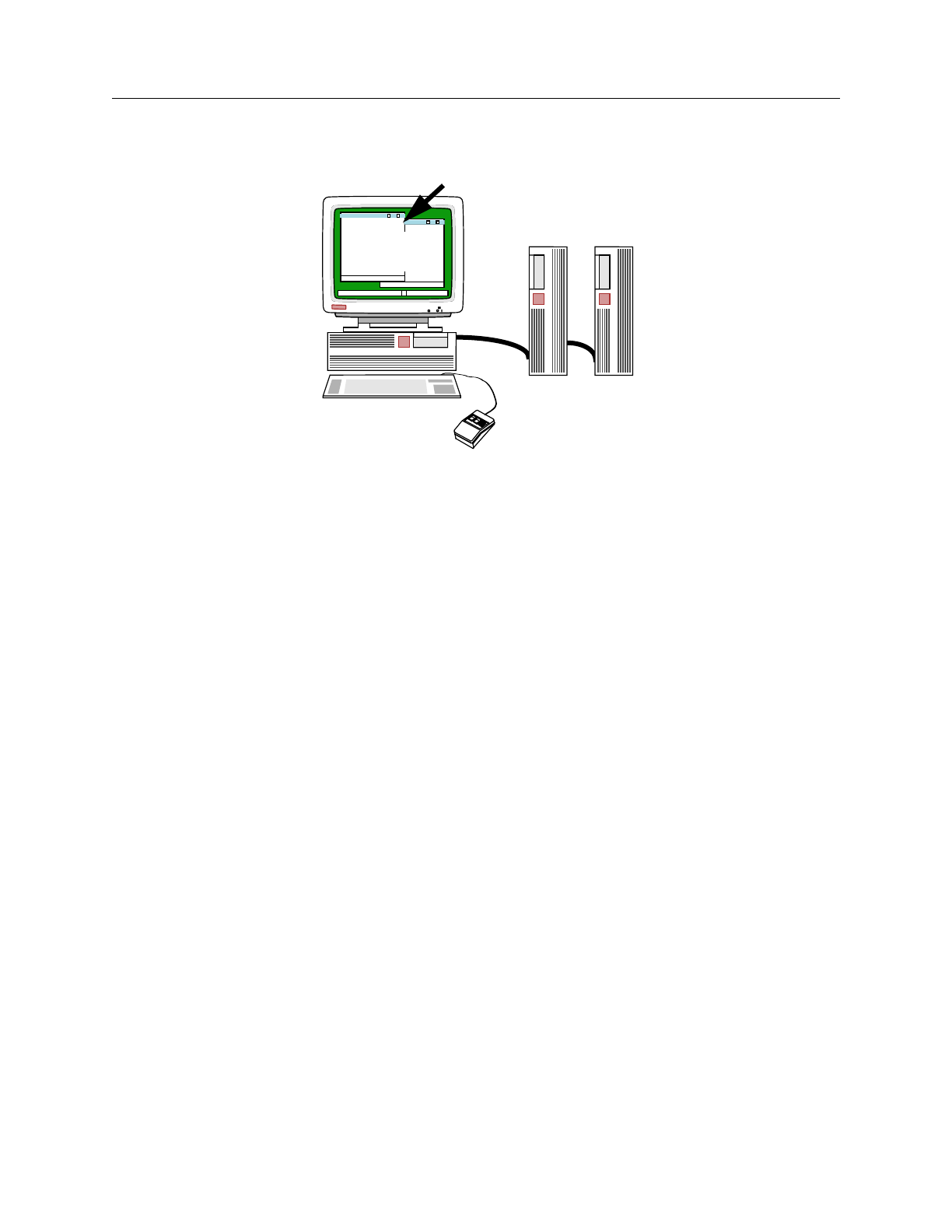
FastScan and FlexTest Reference Manual, V8.6_4
5-2
Distributed FlexTest
Figure 5-1. Master and Slave Workstations
Distributed FlexTest checks for licenses according to the following:
•Master Process - A master process is required to have a full FlexTest
license and a distributed key (another full FlexTest license).
•Slave Process - A slave process is required to have a full FlexTest license
and a distributed key (another full FlexTest license).
Different types of workstations can be used for parallel execution of FlexTest. For
example, parallel ATPG may be invoked on a group of machines consisting of
HP-UX, Sun Solaris, and IBM AIX machines.
Parallelism during ATPG mode is exploited using the data-parallelism afforded
by distributing faults across processes. Due to the differences in the parallel and
serial execution environments and due to the non-determinism during parallel
execution, some variance in fault coverage and test vector lengths is unavoidable.
However, the parallel ATPG implementation tries to minimize such effects. Both
static and dynamic load balancing methods are used to equalize run-time loads
across machines or processors and thus improve the overall throughput. To assist
the load balancing algorithms, you can optionally provide the relative speeds of
various machines in the parallel pool.
$$
FlexTest
Master
Master
Slave Slave
Process

Distributed FlexTest
FastScan and FlexTest Reference Manual, V8.6_4 5-3
Parallelism during Fault Simulation mode is also exploited using data-parallelism
by distributing faults across processors. However, since fault simulation is a
deterministic process, the coverage results in serial and parallel invocations are
the same. Parallel fault simulation is extremely useful in reducing the turnaround
time for fault grading of large functional vector sets. Parallel fault simulation also
uses static and dynamic load balancing to equalize loads at run time.
Distributed FlexTest also has the ability to diagnose problems with remote
processes in case one of the remote processes terminates abnormally or doesn’t
start-up at all.

FastScan and FlexTest Reference Manual, V8.6_4
5-4
Distributed FlexTest
Environment Setup
Before using Distributed FlexTest, you must ensure that the following
environment variables are defined in the shell start-up file (.cshrc or.kshrc) for the
master machine.
•MGLS_LICENSE_FILE - a variable that specifies the location of MGC
license information.
•MGC_HOME - a variable that specifies the location of the FlexTest
software.
The rsh or remsh shell is used to spawn the parallel processes. You should be able
to spawn a remote shell without requiring a password by setting up the appropriate
slave machines in the $HOME/.rhosts file or by setting up the /etc./hosts.equiv file
to declare a set of machines to be equivalent. The appropriate shell start-up file
(.cshrc or.kshrc) is invoked before the remote process is spawned.
Host File Setup
The additional parameters for the slave machines are specified in a Host File that
must be specified at FlexTest invocation.
$MGC_HOME/bin/flextest {{{design_name {{-EDDM [-I | {-S root_name}]} |
-EDIF | -TDL | -VERILOG | -VHDL | -GENIE | -SPICE}} | {-MODEL
cell_name}} [-Library filename] [-SENsitive] [-LOG filename] [-Replace]
[-NOGui] [-Falcon] [-FaultSIM] [-Top model_name] [-DOFile dofile_name]
[-Hostfile host_filename]} | {[-HELP] | [-USAGE] | [-VERSION]}
You can specify the Host File at invocation by using the -Hostfile option at the
shell prompt. You can also specify the Host File in the FlexTest Invocation
Arguments dialog box when using the graphical user interface (see Figure 5-2).
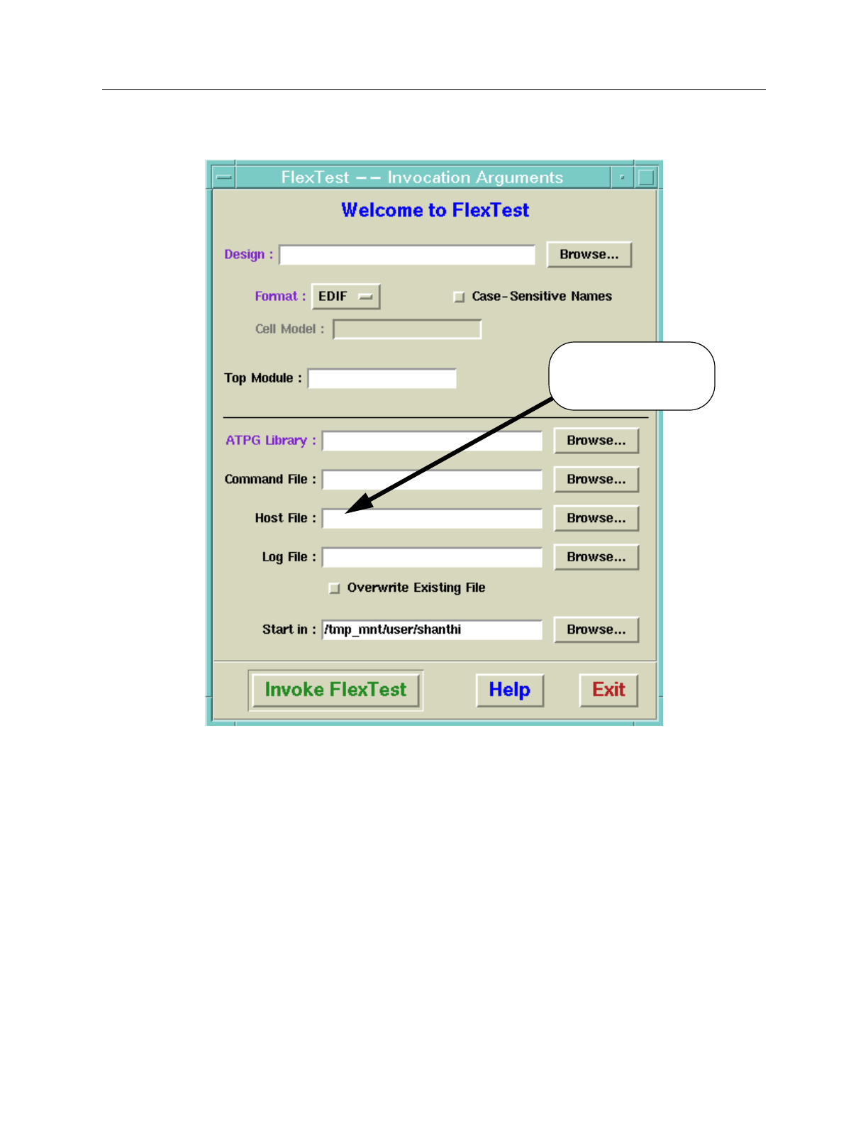
Distributed FlexTest
FastScan and FlexTest Reference Manual, V8.6_4 5-5
Figure 5-2. FlexTest Invocation Arguments Dialog Box
You can enter the path to the Host File in the Host File entry field or use the
Browse button to navigate to the appropriate directory.
Host File
Entry Field

FastScan and FlexTest Reference Manual, V8.6_4
5-6
Distributed FlexTest
Host File Syntax
The -Hostfile option allows you to specify a list of hosts for distributed execution.
Each host is listed in host_filename on a line by itself with some additional
parameters to specify the execution environment on the remote machine. The
following optional parameters may follow a host name (a white space should
separate the host name and the additional parameters):
•mgc=MGC_HOME
Where MGC_HOME is the location of the FlexTest installation tree on the
slave machine. If not specified, the value of MGC_HOME for the spawned
slave process is assumed to be the same as that of the master process.
•wd=WORK_DIR
Where WORK_DIR is the working directory for the remote process. If not
specified, the working directory is assumed to be the same as that of the
master process.
•numt=num_tasks
Where num_tasks is the number of slave processes to spawn on the remote
machine. The default is 1.
•sp=speed
The relative speed rating of the remote host. The default is 1000 (same as
master).
The following is an example of the contents of a Host File:
solaris1 mgc=/user/local/flextest/ss5 wd=/user/jdoe/ckts sp=1000
sunmp1 mgc=/user/local/flextest/ss5 wd=/user/jdoe/ckts numt=4 sp=1000
hpux1 mgc=/user/local/flextest/hpu wd=/user/jdoe/ckts sp=500
ibm1 mgc=/usr/local/flextest/ira wd=/user/jdoe/ckts sp=500 numt=1
If a Host File is specified, FlexTest assumes that you intend to use the hosts for
distributed processing and will attempt to spawn additional FlexTest processes (as
specified by the Host File). You can use the Report Hosts command to list the

Distributed FlexTest
FastScan and FlexTest Reference Manual, V8.6_4 5-7
hosts available for distributed processing. The command also lists working
directories, MGC_HOME path names, the number of tasks scheduled, the relative
speeds and the platform types.

FastScan and FlexTest Reference Manual, V8.6_4
5-8
Distributed FlexTest

FastScan and FlexTest Reference Manual, V8.6_4 A-1
Appendix A
Timing Command Dictionary
This appendix contains descriptions of FastScan and FlexTest timing file
commands. Each tool’s commands appear in separate sections.
•“FastScan Timing Commands” on page A-3 describes the FastScan timing
commands.
•“FlexTest Timing Commands” on page A-32 describes the FlexTest timing
commands.
The “Timing Command Summary” section, which follows, presents a summary of
all the timing commands for both applications.
For information on the methods FastScan and FlexTest use for defining test
pattern timing and performing timing rules checking, refer to “Test Pattern
Formatting and Timing” in the Scan and ATPG Process Guide.
Timing Command Summary
Table A-1 contains a summary of all the timing commands described in this
appendix.
The two columns that separate the command name and the description indicate
which tools support the timing command. The table uses the following tool
acronyms:
FS = FastScan FT = FlexTest

FastScan and FlexTest Reference Manual, V8.6_4
A-2
Timing Command Summary Timing Command Dictionary
Table A-1. Timing Command Summary
Command/Statement F
SF
TDescription
SET BIDI_FORCE TIME •Sets bidirectional pin force time for each
timeframe.
SET CYCLE •Extends the non-scan cycle duration to
ensure stability without adding extra
timeframes.
SET
END_MEASURE_CYCLE
TIME
••Ensures that the primary output measure is
the last event of the test cycle and moves
the measure_sco event to the end of the
previous test cycle. This command cannot
be used with patterns containing a capture
clock. Use the Set Split_measure_cycle
Time command for patterns that contain a
capture clock.
SET FIRST_FORCE TIME •Sets input pin force time for the first
timeframe.
SET FORCE TIME •Sets input pin force time for each
timeframe.
SET MEASURE TIME •Sets output pin measure time for each
timeframe.
SET PROCEDURE FILE ••Specifies which test procedure files to use
during pattern save.
SET SINGLE_CYCLE TIME ••Enables timing rules checking to ensure a
single time exists for both scan and non-
scan test cycles.
SET SKEW_FORCE TIME •Specifies input pin force time for particular
pins in each timeframe.

Timing Command Dictionary FastScan Timing Commands
FastScan and FlexTest Reference Manual, V8.6_4 A-3
FastScan Timing Commands
This section describes, in alphabetical order, the commands that FastScan uses to
define timing information and enable specific timing checks for test patterns.
These commands reside in a timing file--they are not application commands.
Each command description begins on a new page and contains information
indicating the context, or scope, for the command’s use.
SET SPLIT_BIDI_CYCLE
TIME ••Specifies the period for test procedures and
splits the non-scan cycle before the force or
bidi_force time.
SET
SPLIT_MEASURE_CYCLE
TIME
••Specifies the period for test procedures and
splits the non-scan cycle at the measure
time.
SET STROBE_WINDOW
TIME ••Specifies the strobe window width.
SET TIME SCALE ••Sets the time scale and unit.
TIMEPLATE •Defines non-scan event timing.
Table A-1. Timing Command Summary [continued]
Command/Statement F
SF
TDescription
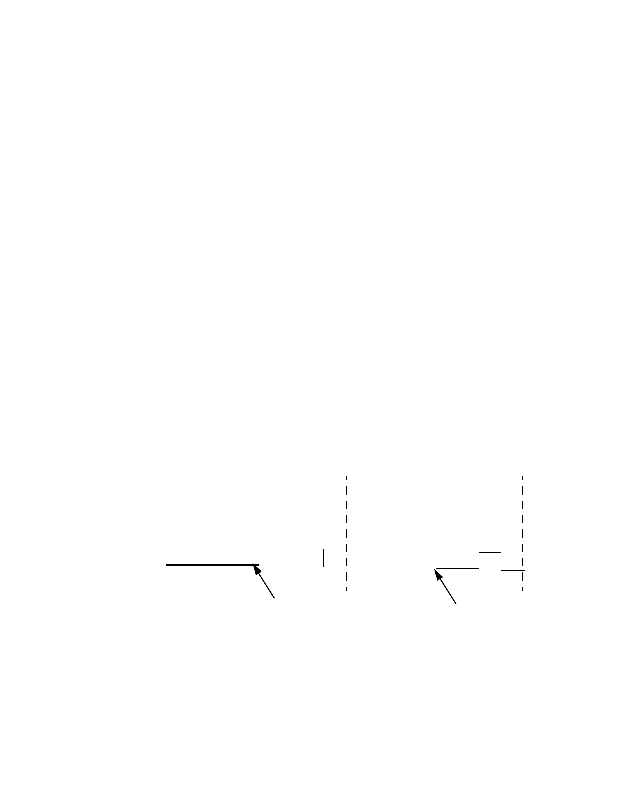
FastScan and FlexTest Reference Manual, V8.6_4
A-4
SET END_MEASURE_CYCLE TIME Timing Command Dictionary
SET END_MEASURE_CYCLE TIME
Scope: Enables special timing rules checking
Usage
SET END_MEASURE_CYCLE TIME integer
Description
Ensures that the primary output measure is the last event of the test cycle and
moves the measure_sco event to the end of the previous test cycle. This command
cannot be used with patterns containing a capture clock. Use the Set
Split_measure_cycle Time command for patterns that contain a capture clock.
Certain tester formats, such as TDL 91, expect all measures to occur at the end of
the tester cycle. However, the scan output pin comparison always occurs in the
shift procedure prior to the shift clock application. The tester should measure scan
output pins in the shift procedure at the end of the test cycle. Therefore, when you
specify this command, the test pattern formatter safely moves the scan output
measure event to the end of the previous cycle. The first measure_sco event
moves to the end of the load_unload procedure cycle and each succeeding
measure_sco event moves to the previous shift procedure cycle.
Figure A-1 depicts the effect of the SET END_MEASURE_CYCLE TIME
command on the test procedure test cycles.
Figure A-1. Scan Event Timing for SET END_MEASURE_CYCLE
TIME
load_unload shift #1 shift #N
. . .
measure_sco measure_sco
(repeatedly
apply shift)
capture
clock

Timing Command Dictionary SET END_MEASURE_CYCLE TIME
FastScan and FlexTest Reference Manual, V8.6_4 A-5
Note that the measure_sco event for the first shift procedure cycle occurs at the
end of the load_unload procedure. All other measure_sco events for shift cycles
occur at the end of the previous shift cycles.
Unlike the SET SPLIT_MEASURE_CYCLE TIME command, this command
ensures that all test cycles have measure events at the end--without splitting the
original test cycle in two. Note that you can specify only one of the following
commands in a timing file:
•SET SINGLE_CYCLE TIME
•SET SPLIT_BIDI_CYCLE TIME
•SET END_MEASURE_CYCLE TIME
•SET SPLIT_MEASURE_CYCLE TIME
If you place the SET END_MEASURE_CYCLE TIME command in the timing
file, the timing rules checker ensures compliance to the following conditions:
•The timeplate period equals the end_measure_cycle time that you specify
with the SET END_MEASURE_CYCLE TIME.
•The period of all scan test procedures either equals the end_measure_cycle
time or is the end_measure_cycle time multiplied by the number of test
cycles in the test procedure.
•The end_measure_cycle time is greater than the measure_po time and equal
to the period of the super timeplate.
•The timing in each timeplate corresponds to the timing in the super
timeplate.
•The end_measure_cycle command is only valid for test patterns that do not
have a capture clock or that use clock sequential patterns.
•Each test procedure force event time for a clock pin corresponds to the
capture clock timing in the super timeplate.

FastScan and FlexTest Reference Manual, V8.6_4
A-6
SET END_MEASURE_CYCLE TIME Timing Command Dictionary
•Each test procedure force event time on a non-clock pin corresponds to the
force_pi time in the super timeplate.
•The measure_sco time in the shift procedure, which defines when the scan
output measure should occur, is zero.
In some tester formats (such as UTIC), you can specify a separate timing
definition for the shift procedure. In this case, the timing rules checker does not
consider the shift procedure for compliance with the constraints listed earlier.
Arguments
•integer
An integer time value specifying the final test cycle length. This number must
match the period of the shift procedure.
Examples
The following example specifies a timing definition that satisfies all the
constraints described previously. Note that the end_measure_cycle time is greater
than the measure_po time. Note also the absence of capture clocks in the timeplate
definition. FastScan generates patterns without capture clocks for testing IDDQ
faults and observing clock faults at a primary output pin.
Assume the timing file contains the following commands:
SET TIME SCALE 1 ns;
SET END_MEASURE_CYCLE TIME 500; //matches period of shift
TIMEPLATE “tp4”
FORCE_PI 0;
BIDI_FORCE_PI 100;
WRITE_RAM_CLOCK_ON 200;
WRITE_RAM_CLOCK_OFF 300;
MEASURE_PO 400;
PERIOD 500;
END;
SET PROCEDURE FILE “g1” “design.g1”;

Timing Command Dictionary SET END_MEASURE_CYCLE TIME
FastScan and FlexTest Reference Manual, V8.6_4 A-7
The design.g1 test procedure file contains the following shift procedure for scan
group g1:
PROC SHIFT =
FORCE_SCI 0;
MEASURE_SCO 0; // must happen at time 0
FORCE clk_a 1 300;
FORCE clk_a 0 400;
PERIOD 500;
END;
Related Commands
SET SINGLE_CYCLE TIME
SET SPLIT_BIDI_CYCLE TIME SET SPLIT_MEASURE_CYCLE TIME

FastScan and FlexTest Reference Manual, V8.6_4
A-8
SET PROCEDURE FILE Timing Command Dictionary
SET PROCEDURE FILE
Scope: Sets timing information
Usage
SET PROCEDURE FILE {“scan_group_name”“filename”}...
Description
Specifies which test procedure files to use during pattern save.
ATPG requires the test procedure file to contain the proper sequence of events,
but does not require it to specify the real timing information. However, simulators
and ATE do require this information. Thus, you must edit your test procedure files
to include real timing information after you run the ATPG process. You then use
the SET PROCEDURE FILE command to specify the proper test procedure file.
This command lets you specify multiple scan groups and their associated test
procedure files. If you use this command without specifying the scan group name
and test procedure file name, the tool uses the original test procedure file to update
the time values for all scan groups.
Arguments
•“scan_group_name”
A quoted string that specifies the name of the scan group to which the test
procedure file applies. You must surround this argument in double-quotes.
•“filename”
A quoted string that specifies the name of the test procedure file for the
specified scan group. You must surround this argument in double-quotes.
Note
When you modify the test procedure file, you can only add real
timing values; you cannot delete, reorder, or change any
statements—and that includes adding break or break_repeat
statements.


FastScan and FlexTest Reference Manual, V8.6_4
A-10
SET SINGLE_CYCLE TIME Timing Command Dictionary
SET SINGLE_CYCLE TIME
Scope: Enables special timing rules checking
Usage
SET SINGLE_CYCLE TIME integer
Description
Enables timing rules checking to ensure a single time exists for both scan and non-
scan test cycles.
Some tester formats, such as Compass Scan, TDL 91, and FTDL-E, allow only a
single timing definition for each tester cycle. As a result, both the scan test
procedure and the non-scan cycle must use the same timing. The SET
SINGLE_CYCLE TIME command enables the ASICVector Interfaces (AVI)
functionality to perform this timing check.
If you place this command in the timing file, the timing rules checker ensures
compliance to the following conditions:
•The period of all scan test procedures and timeplates equals either the
single_cycle time or the number of cycles multiplied by the single_cycle
time.
•The period of all the pins equals the single_cycle time.
•The timing specified in each timeplate corresponds to the timing specified
in the super timeplate.
•For each scan test procedure, each force event time on a clock pin occurs at
the force offset time in each cycle, as specified in the super timeplate.
•For each scan test procedure, each force event on a non-clock pin occurs at
the force offset time in each cycle, as specified in the super timeplate.
Note that you can specify only one of the following commands in a timing file:
•SET SINGLE_CYCLE TIME
•SET SPLIT_BIDI_CYCLE TIME

Timing Command Dictionary SET SINGLE_CYCLE TIME
FastScan and FlexTest Reference Manual, V8.6_4 A-11
•SET END_MEASURE_CYCLE TIME
•SET SPLIT_MEASURE_CYCLE TIME
Arguments
•integer
Time value that specifies both the scan and non-scan cycle duration. This
number must match the shift procedure period.
Examples
The following example satisfies all the timing constraints listed in the command
description. Note that the shift clock timing and the capture clock timing are
identical.
Assume the timing file contains the following commands:
// FastScan timing file
SET TIME SCALE 1 ns;
SET SINGLE_CYCLE TIME 1000;
TIMEPLATE “tp4” =
FORCE_PI 0;
BIDI_FORCE_PI 100;
WRITE_RAM_CLOCK_ON 200;
WRITE_RAM_CLOCK_OFF 300;
MEASURE_PO 400;
CAPTURE_CLOCK_ON 500;
CAPTURE_CLOCK_OFF 600;
PERIOD 1000;
END;
SET PROCEDURE FILE “g1” “design.g1”;
The design.g1 test procedure file contains the following shift procedure for scan
group g1:
PROC SHIFT =
FORCE_SCI 0;
MEASURE_SCO 400;
FORCE clk_a 1 500;
FORCE clk_a 0 600;
PERIOD 1000;
END;

FastScan and FlexTest Reference Manual, V8.6_4
A-12
SET SPLIT_BIDI_CYCLE TIME Timing Command Dictionary
SET SPLIT_BIDI_CYCLE TIME
Scope: Enables special timing rules checking
Usage
SET SPLIT_BIDI_CYCLE TIME integer
Description
Specifies the period for test procedures and splits the non-scan cycle before the
force or bidi_force time.
Certain tester formats, such as UTIC and Compass Scan, do not allow state
changes on both input pins and bidirectional pins in a single tester cycle. In this
case, you must split each non-scan cycle into two tester cycles. The SET
SPLIT_BIDI_CYCLE TIME command enables the ASICVector Interfaces (AVI)
functionality to split the non-scan test cycle into two tester cycles when writing
patterns.
If you place this command in the timing file, the timing rules checker ensures
compliance to the following conditions:
•The timeplate periods are all twice the split_bidi_cycle time.
•The period of all scan test procedures equals the split_bidi_cycle time
multiplied by the number of cycles in the test procedure.
•The super timeplate contains a bidi_force_pi event.
•The split_bidi_cycle time is greater than the force_pi time and less than or
equal to the bidi_force_pi time in the super timeplate.
•The timing of each timeplate is compatible with the super timeplate. For
example, the force_pi time in each timeplate should occur at the same time
as in the super timeplate.
•For each scan test procedure, each force event time on a clock pin
corresponds to the split_bidi_cycle time minus the super timeplate clock
force times.

Timing Command Dictionary SET SPLIT_BIDI_CYCLE TIME
FastScan and FlexTest Reference Manual, V8.6_4 A-13
•For each scan test procedure, each force event time on a non-clock pin
corresponds to the split_bidi_cycle time minus the force_pi times in the
super timeplate.
The tool subtracts the split_bidi_cycle time from the timeplate force times before
performing this check. Refer to the example that follows for details.
Note that you can specify only one of the following commands in a timing file:
•SET SINGLE_CYCLE TIME
•SET SPLIT_BIDI_CYCLE TIME
•SET END_MEASURE_CYCLE TIME
•SET SPLIT_MEASURE_CYCLE TIME
Arguments
•integer
The time value at which to split the non-scan test cycle. This number must
match the period of the shift procedure.
Examples
The following example shows a timing definition satisfying all the conditions
specified in the command description. Note that the shift clock timing and the
capture clock timing are compatible. Also, note that the split_bidi_cycle time is
greater than the force time and less than the bidi_force time in the first timeframe
(0 < 500 < 550).

FastScan and FlexTest Reference Manual, V8.6_4
A-14
SET SPLIT_BIDI_CYCLE TIME Timing Command Dictionary
//FastScan Timing file
SET TIME SCALE 1 ns;
SET SPLIT_BIDI_CYCLE TIME 500; // matches shift period
TIMEPLATE “tp4” =
FORCE_PI 0; //only event in first cycle
// cycle split at time 500, prior to bidi force
BIDI_FORCE_PI 550; // time 50 of second cycle
WRITE_RAM_CLOCK_ON 600; // time 100 of second cycle, etc
WRITE_RAM_CLOCK_OFF 650;
MEASURE_PO 700;
CAPTURE_CLOCK_ON 800;
CAPTURE_CLOCK_OFF 900;
PERIOD 1000;
END;
SET PROCEDURE FILE “g1” “design.g1”;
//Test procedure file
PROC SHIFT =
FORCE_SCI 0;
MEASURE_SCO 200;
FORCE clk_a 1 300; // equals timeplate capture clock
FORCE clk_a 0 400; // times minus split_bidi time
PERIOD 500;
END;
Related Commands
SET SINGLE_CYCLE TIME SET SPLIT_MEASURE_CYCLE
TIME
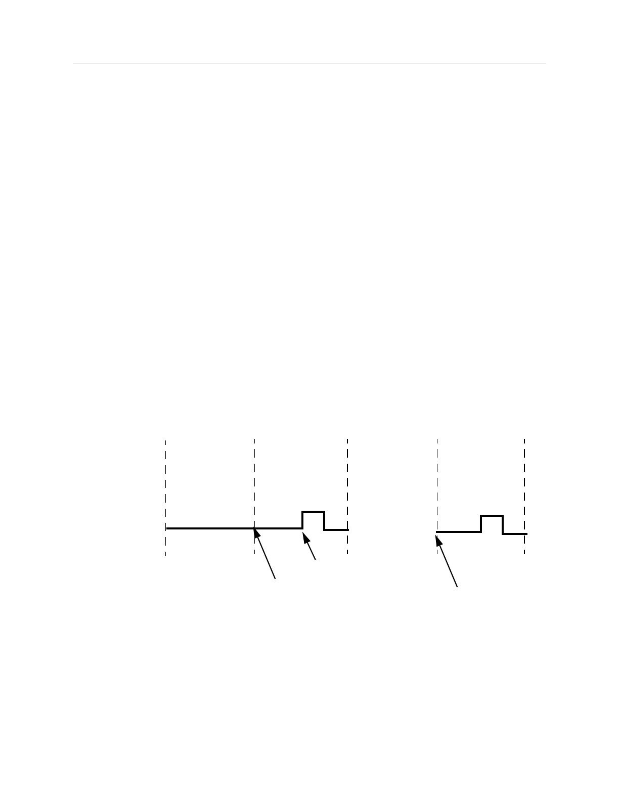
Timing Command Dictionary SET SPLIT_MEASURE_CYCLE TIME
FastScan and FlexTest Reference Manual, V8.6_4 A-15
SET SPLIT_MEASURE_CYCLE TIME
Scope: Enables special timing rules checking
Usage
SET SPLIT_MEASURE_CYCLE TIME integer
Description
Specifies the period for test procedures and splits the non-scan cycle at the
measure time.
Certain tester formats, such as TDL 91, expect all measures to occur last in the
tester cycle. However, the scan output pin comparison always occurs in the shift
procedure prior to the shift clock application. The tester should measure scan
output pins in the shift procedure at time zero. Therefore, when you specify this
command, the test pattern formatter safely moves the scan output measure event
(measure_sco) so that it is the last event in the previous cycle. The first
measure_sco event moves to the end of the load_unload procedure cycle and
each succeeding measure_sco event moves to the previous shift procedure cycle.
Figure A-2 depicts the effect of the SET SPLIT_MEASURE_CYCLE TIME
command on the test procedure test cycles.
Figure A-2. Scan Event Timing for SET SPLIT_MEASURE_CYCLE
TIME
Note that the measure_sco event for the first shift procedure cycle occurs at the
end of the load_unload procedure. All other measure_sco events for shift cycles
occur at the end of the previous shift cycles.
load_unload shift #1 shift #N
. . .
measure_sco measure_sco
(repeatedly
apply shift)
capture
clock
capture_clock_on

FastScan and FlexTest Reference Manual, V8.6_4
A-16
SET SPLIT_MEASURE_CYCLE TIME Timing Command Dictionary
This command can also cause the application to split the non-scan test cycle into
two tester cycles. The application splits the test cycle only if the measure_po event
does not already occur as the last event of the test cycle.
If you place this command in the timing file, the timing rules checker ensures
compliance to the following conditions:
•The timeplate period is twice that of the split_measure_cycle time (unless
the timeplate begins with init_force_pi, in which case the timeplate period
is four times that of the split_measure_cycle time).
•The period of all scan test procedures equals the split_measure_cycle time
multiplied by the number of test cycles in the test procedure.
•The split_measure_cycle time is greater than the measure_po time and less
than the capture_clock_on time in the super timeplate.
•The timing in each timeplate corresponds to the timing in the super
timeplate.
•For clock pins, each test procedure force event time corresponds to the
capture clock timing in the super timeplate. Note that the tool subtracts the
split_measure_cycle time from the capture_clock times before this check.
•Each test procedure force event on a non-clock pin corresponds to the
force_pi time in the super timeplate.
•The measure_sco time in the shift procedure, which defines when the scan
output measure should occur, is zero.
Note that you can specify only one of the following commands in a timing file:
•SET SINGLE_CYCLE TIME
•SET SPLIT_BIDI_CYCLE TIME
•SET END_MEASURE_CYCLE TIME
•SET SPLIT_MEASURE_CYCLE TIME

Timing Command Dictionary SET SPLIT_MEASURE_CYCLE TIME
FastScan and FlexTest Reference Manual, V8.6_4 A-17
Arguments
•integer
The time value at which to split the cycle. This number must match the period
of the shift procedure.
Examples
The following FastScan example writes out a pattern set that tests for transition
faults. When init_force_pi is the first non-scan event in the cycle, FastScan splits
the ATPG non-scan cycle into two cycles. The first cycle includes only the
init_force_pi event, while the second cycle begins with the force_pi and includes
the remaining events in the non-scan cycle. When specified in the timing file, the
SET SPLIT_MEASURE_CYCLE TIME command further splits each of these
two cycles, causing the measure_po event to be the last event of the new test
cycle.
So the timeplate timing definition should specify that the force_pi event time
equals 2*test_cycle_length. Also, the period of the whole ATPG cycle should
equal 4*test_cycle_length. These calculations assume the SET
SPLIT_MEASURE_CYCLE command specifies test_cycle_length.
This example demonstrates the proper timing definition for this situation.
//FastScan application commands
add scan group g1 ckt2.tp
add scan chain c1 g1 SI SO
set fault type transition
add clocl 1 clks
add clocl 0 clk
set DRC handling C2 war
set system mode atpg
add faults -all
run
save patterns pattern_file -replace time_file -Zycad -serial
//Timing file “time_file”
set time scale 1 ns;
Timeplate "tp0" =
init_force_pi 0;
force_pi 400;
measure_po 520;

FastScan and FlexTest Reference Manual, V8.6_4
A-18
SET SPLIT_MEASURE_CYCLE TIME Timing Command Dictionary
capture_clock_on 650;
capture_clock_off 700;
period 800;
end;
set split_measure_cycle time 200;
set procedure file "g1" "ckt2.tp";
//Test procedure file “ckt2.tp”
procedure test_setup =
//test cycle 1
force clk 0 0;
force clk 1 50;
force clk 0 100;
//test cycle 2
force clk 0 200;
force clk 1 250;
force clk 0 300;
//test cycle 3
force clk 0 400;
force clk 1 450;
force clk 0 500;
//test cycle 4
force clk 0 600;
force clk 1 650;
force clk 0 700;
period 800;
end;
procedure shift =
force_sci 0;
measure_sco 0;
force clk 1 50;
force clk 0 100;
period 200;
end;
procedure load_unload =
force SE 1 0;
force CLK 0 0;
force CLKS 1 0;
period 200;
end;
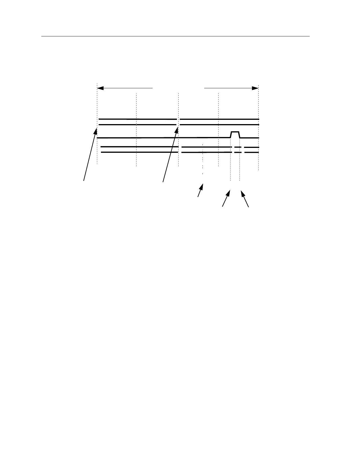
Timing Command Dictionary SET SPLIT_MEASURE_CYCLE TIME
FastScan and FlexTest Reference Manual, V8.6_4 A-19
Figure A-3 shows the non-scan test cycle timing for this example. Notice how the
init_force_pi and SET SPLIT_MEASURE_CYCLE TIME splits the cycle time
into four test cycles (each equal to one fourth of the timeplate period).
Figure A-3. SET SPLIT_MEASURE_CYCLE TIME Non-scan Event
Timing Diagram
Related Commands
SET END_MEASURE_CYCLE TIME
SET SINGLE_CYCLE TIME SET SPLIT_BIDI_CYCLE TIME
0ns
CLK
X
PIs
800ns
measure_po
Test Cycle
600ns
400ns 200ns
X
Test Cycle Test Cycle Test Cycle
2 1 3 4
POs XX
520 650 700
XX
capture_clock_on
force_piinit_force_pi
capture_clock_off
timeplate period

FastScan and FlexTest Reference Manual, V8.6_4
A-20
SET STROBE_WINDOW TIME Timing Command Dictionary
SET STROBE_WINDOW TIME
Scope: Enables special timing rules checking
Usage
SET STROBE_WINDOW TIME integer
Description
Specifies the strobe window width.
Some tester formats can measure primary outputs (POs) at the exact time that you
specify with the measure_po statement in the timeplate. However, other tester
formats, such as UTIC, require that output measurements occur during a specified
window of time (strobe window). You can set this strobe window using the SET
STROBE_WINDOW TIME command.
If you specify this command in the timing file, the timing rules checker ensures
that the difference between the measure_po time and the capture_clock_on time
equals or exceeds the strobe_window time. This is to ensure that the outputs
remain stable during the strobe window. Note that for some formats, such as TSSI
WGL, this command changes the strobe window in the output file.
Arguments
•integer
The length of time after the measure event, in which no event should occur.
Example
The following timing file example illustrates how to set a strobe window to 50ns
which allows the measure_po (set to 400ns) to actually occur anytime between
400 and 450ns:
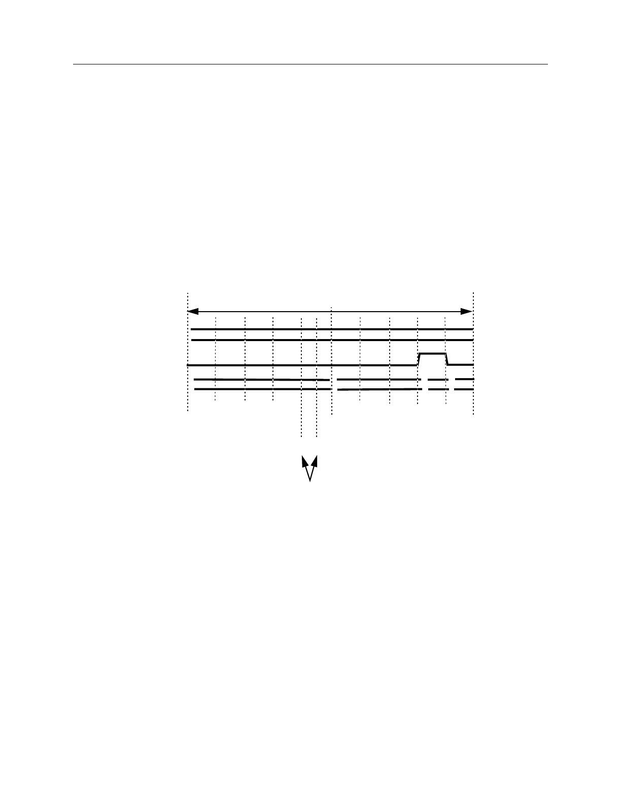
Timing Command Dictionary SET STROBE_WINDOW TIME
FastScan and FlexTest Reference Manual, V8.6_4 A-21
SET TIME SCALE 1 ns;
SET STROBE_WINDOW TIME 50;
TIMEPLATE “tp4” PERIOD 1000;
FORCE_PI 0;
BIDI_FORCE_PI 100;
WRITE_RAM_CLOCK_ON 200;
WRITE_RAM_CLOCK_OFF 300;
MEASURE_PO 400;
CAPTURE_CLOCK_ON 800;
CAPTURE_CLOCK_OFF 900;
END;
Figure A-4 shows the output strobe window for this example.
Figure A-4. SET STROBE_WINDOW Timing Diagram
Related Commands
None.
0ns
CLK
X
PIs
1000ns
Strobe Window
500ns
Test Cycle
POs XXX
X
450
400
(measure_po can occur anytime within this window)

FastScan and FlexTest Reference Manual, V8.6_4
A-22
SET TIME SCALE Timing Command Dictionary
SET TIME SCALE
Scope: Sets timing information
Usage
SET TIME SCALE number unit
Description
Sets the time scale and unit.
FastScan applies the timing scale and unit you specify in the timing file to the test
procedure file and timeplates. If you do not specify this command, the default
value for the timing scale is 1000ns.
Arguments
•number
The factor multiplied by all time values to get the actual time values. The
number argument can be any real number, the default being 1000.
•unit
The time scale unit, such as ns (the default), ps, ms, or us.
Examples
The following command specified in the timing file sets the time scale to 1
nanosecond.
SET TIME SCALE 1 ns;
Related Commands
SET PROCEDURE FILE

Timing Command Dictionary TIMEPLATE
FastScan and FlexTest Reference Manual, V8.6_4 A-23
TIMEPLATE
Scope: Sets timing information
Usage
TIMEPLATE “timeplate_name”=
timeplate_statement;...
END;
Description
Defines non-scan event timing.
FastScan uses timeplate definitions within a timing file to specify timing
waveforms for non-scan related event groups. For more information on
timeplates, refer to “Test Pattern Formatting and Timing” in the Scan and ATPG
Process Guide.
FastScan tries to match the exact timeplate to an event group for a particular
pattern. If such a timeplate does not exist, FastScan chooses another timeplate that
contains all events in the current pattern. This super timeplate contains a superset
of the events of all other timeplates for the pattern set. FastScan requires a super
timeplate when the test format you wish to write allows only a single timing
definition. At a minimum, you need only specify the super timeplate for all non-
scan event groups.
FastScan can also write default timeplates required for the event groups of the
pattern set. For more information, refer to the Write Timeplate application
command description in Chapter 2.
Arguments
•“timeplate_name”=
A quoted string and equal sign that specifies the name of the timeplate for a
particular non-scan event group. You must surround the name in double-quotes
and end it with an equal sign (=).

FastScan and FlexTest Reference Manual, V8.6_4
A-24
TIMEPLATE Timing Command Dictionary
•timeplate_statement;
A set of statements, each ending with a semi-colon (;), that comprise the body
of the timeplate file. For each statement, the time value must be either 0 or a
positive integer. Also, timeplate statements can include comments. Comment
text (text on a line following “//”) does not affect timeplate statement execution
in any way.
When you issue the Write Timeplate command, FastScan automatically
generates the appropriate timeplate statements within the necessary timeplates
for the pattern set. Timeplate statements include the following:
INIT_FORCE_PI time — Specifies the initial primary input force time for
transition fault testing. When used, this statement must occur first in the
timeplate.
Note that this timeplate statement is similar to the SET FIRST_FORCE
TIME command that FlexTest uses in the timing file.
FORCE_PI time — Specifies the force time for all primary inputs. The
time you specify must be greater than the INIT_FORCE_PI time if you use
that statement.
Note that this timeplate statement is similar to the SET FORCE TIME
command that FlexTest uses in the timing file.
BIDI_FORCE_PI time — Specifies the force time for all bidirectional
pins. This statement lets you force the bidi pins after applying the tri-state
control signal so the system avoids bus contention. The time you specify
should be greater than the FORCE_PI time, and less than both the
WRITE_RAM_CLOCK_ON and MEASURE_PO times.
Note that this timeplate statement is similar to the SET BIDI_FORCE
TIME command that FlexTest uses in the timing file.
SKEW_FORCE_PI “pin_name”... time — Specifies the force time for
specific pins. This statement lets you specify a force time for pins with
special circumstances. For example, pins that clock only non-scan latches
can cause setup and hold violations if they change at the same time as other
inputs, so they may require a different force time. The time you specify
should be less than both the WRITE_RAM_CLOCK_ON and
MEASURE_PO times.

Timing Command Dictionary TIMEPLATE
FastScan and FlexTest Reference Manual, V8.6_4 A-25
A single timeplate can contain more than one SKEW_FORCE_PI
statement. Each SKEW_FORCE_PI statement can specify multiple pin
names with the same force time. Each pin name you specify must appear in
double-quotes.
Note that this timeplate statement is similar to the SET SKEW_FORCE
TIME command that FlexTest uses in the timing file.
WRITE_RAM_CLOCK_ON time — Specifies the time at which the tool
forces the RAM write lines on. The RAM write control statements can
occur at different times within the timeplate, depending on the patterns the
timeplate supports. The Write Timeplate command puts the
WRITE_RAM_CLOCK_ON and WRITE_RAM_CLOCK_OFF
statements in the proper sequence in the timeplates it generates.
WRITE_RAM_CLOCK_OFF time — Specifies the time at which the
tool forces the RAM write lines off.
SKEW_WRITE_RAM_CLOCK_ON “pin_name”time — Specifies the
time at which the tool forces particular RAM write lines on.
A single timeplate can contain more than one
SKEW_WRITE_RAM_CLOCK_ON statement. Each
SKEW_WRITE_RAM_CLOCK_ON statement can specify multiple pin
names with the same force time. Each pin name you specify must appear in
double-quotes.
SKEW_WRITE_RAM_CLOCK_OFF “pin_name”time — Specifies
the time at which the tool forces particular RAM write lines off.
A single timeplate can contain more than one
SKEW_WRITE_RAM_CLOCK_OFF statement. Each
SKEW_WRITE_RAM_CLOCK_OFF statement can specify multiple pin
names with the same force time. Each pin name you specify must appear in
double-quotes.
MEASURE_PO time — Specifies the time at which the tool measures, or
strobes, the primary outputs.
Note that this timeplate statement is similar to the SET MEASURE TIME
command that FlexTest uses in the timing file.
CAPTURE_CLOCK_ON time — Specifies the time at which the tool
forces the capture clock to its on state. FastScan measures output pins

FastScan and FlexTest Reference Manual, V8.6_4
A-26
TIMEPLATE Timing Command Dictionary
before the capture clock pulses in a non-scan cycle (the MEASURE_PO
event must occur prior to the capture clock).
CAPTURE_CLOCK_OFF time — Specifies the time at which the tool
forces the capture clock to its off state.
SKEW_CAPTURE_CLOCK_ON “pin_name” time — Specifies the
force on time for the capture clock. For example, this statement lets you
specify different timing for the LSSD_A and LSSD_B clocks, to ensure the
timing coincides with the shift procedure.
The time you specify should be greater than the MEASURE_PO time.
A single timeplate can contain more than one
SKEW_CAPTURE_CLOCK_ON statement. Each
SKEW_CAPTURE_CLOCK_ON statement can specify multiple pin
names with the same force time. Each pin name you specify must appear in
double-quotes.
SKEW_CAPTURE_CLOCK_OFF “pin_name”time — Specifies the
force off time for the capture clock. For example, this statement lets you
specify different timing for the LSSD_A and LSSD_B clocks, to ensure the
timing coincides with the shift procedure.
The time you specify should be greater than the
SKEW_CAPTURE_CLOCK_ON time.
A single timeplate can contain more than one
SKEW_CAPTURE_CLOCK_OFF statement. Each
SKEW_CAPTURE_CLOCK_OFF statement can specify multiple pin
names with the same force time. Each pin name you specify must appear in
double-quotes.
DUMMY_CLOCK_ON time — Specifies the time at which the tool
forces on the dummy clocks. Dummy clock statements support both IDDQ
pattern sets and pattern sets containing patterns using clock procedures. For
example, when the test pattern format requires a single timing definition,
and the pattern set does not pulse the capture clock within the patterns (as is
the case with IDDQ patterns), then the non-scan timing would not match
the test procedure timing for the load_unload and shift procedures (which
do pulse clocks). In this situation, you could add dummy clock statements

Timing Command Dictionary TIMEPLATE
FastScan and FlexTest Reference Manual, V8.6_4 A-27
to mimic a clock pulsing in the non-scan timing definition, even though the
patterns do not contain clock pulse events.
This event must occur after all force events and before the
DUMMY_CLOCK_OFF event. A timeplate that specifies dummy clock
timing cannot specify capture clock events.
DUMMY_CLOCK_OFF time — Specifies the time in which to force off
the dummy clocks used in clock procedures. This event must occur after the
DUMMY_CLOCK_ON event and before the MEASURE_PO event.
SKEW_DUMMY_CLOCK_ON “pin_name” time — Specifies the time
in which to force particular dummy clocks on.
A single timeplate can contain more than one
SKEW_DUMMY_CLOCK_ON statement. Each
SKEW_DUMMY_CLOCK_ON statement can specify multiple pin names
with the same force time. Each pin name you specify must appear in
double-quotes.
SKEW_DUMMY_CLOCK_OFF “pin_name” time — Specifies the time
in which to force particular dummy clocks off.
A single timeplate can contain more than one
SKEW_DUMMY_CLOCK_OFF statement. Each
SKEW_DUMMY_CLOCK_OFF statement can specify multiple pin names
with the same force time. Each pin name you specify must appear in
double-quotes.
PERIOD time — Specifies the period of the non-scan test cycle. This
statement lets you ensure that the cycle contains sufficient time after the last
force event for the circuit to stabilize.
The time you specify should be greater than or equal to the final event time.
Note that this timeplate statement is similar to the SET CYCLE command
that FlexTest uses in the timing file.
•END;
A literal and semi-colon (;) that specifies to terminate the TIMEPLATE
statement.

FastScan and FlexTest Reference Manual, V8.6_4
A-28
TIMEPLATE Timing Command Dictionary
Examples
Example 1 shows a timeplate that illustrates many of the possible statements:
TIMEPLATE “tp1” =
FORCE_PI 0;
SKEW_FORCE_PI “cntrl” 50; //bidi control pin
BIDI_FORCE_PI 70;
MEASURE_PO 90;
CAPTURE_CLOCK_ON 100;
CAPTURE_CLOCK_OFF 200;
SKEW_CAPTURE_CLOCK_ON “lssd_b” 200;
SKEW_CAPTURE_CLOCK_OFF “lssd_b” 225;
PERIOD 250;
END;
Figure A-5 illustrates Example 1, showing the timing diagrams generated for an
input pin ENABLE, bidirectional pin ABUS, bidi control pin CNTRL, and the
clock pin.
Figure A-5. Template Timing for Example 1
Example 2 shows a timing file, which contains four timeplates, for a design with
RAMs and bidirectional pins. Note that super timeplate “tp4” is a superset of the
events in timeplates “tp1”, “tp2”, and “tp3”:
0 50 70 90 100 150 200 250
ENABLE
CNTRL
ABUS
CLK
LSSD_B
225
Test Cycle

Timing Command Dictionary TIMEPLATE
FastScan and FlexTest Reference Manual, V8.6_4 A-29
TIMEPLATE “tp1” =
FORCE_PI 0;
BIDI_FORCE_PI 100;
WRITE_RAM_CLOCK_ON 200;
WRITE_RAM_CLOCK_OFF 300;
PERIOD 1000;
END;
TIMEPLATE “tp2” =
FORCE_PI 0;
BIDI_FORCE_PI 100;
MEASURE_PO 400;
CAPTURE_CLOCK_ON 500;
CAPTURE_CLOCK_OFF 600;
PERIOD 1000;
END;
TIMEPLATE “tp3” =
FORCE_PI 0;
BIDI_FORCE_PI 100;
MEASURE_PO 400;
PERIOD 1000;
END;
TIMEPLATE “tp4” =
FORCE_PI 0;
BIDI_FORCE_PI 100;
WRITE_RAM_CLOCK_ON 200;
WRITE_RAM_CLOCK_OFF 300;
MEASURE_PO 400;
CAPTURE_CLOCK_ON 500;
CAPTURE_CLOCK_OFF 600;
PERIOD 1000;
END;
Example 3 shows the application commands, a timeplate file using dummy clock
statements intended to support a pattern set based on clock procedures, and the
corresponding test procedure file:
// FastScan application commands
add scan groups g1 counter.g1
add scan chain c1 g1 si so
add clocks 0 clk

FastScan and FlexTest Reference Manual, V8.6_4
A-30
TIMEPLATE Timing Command Dictionary
add clocks 1 clear
set system mode atpg
add fault -all
run
save pattern counter.tssi.ser counter.fst.time -tssi -ser
// Timing file “counter.fst.time”
set time scale 1 ns;
Timeplate "tp0" =
force_pi 2;
dummy_clock_on 100;
dummy_clock_off 200;
measure_po 490;
period 500;
end;
set end_measure_cycle time 500;
set procedure file "g1" "counter.ti.g1.split";
// Test procedure file “counter.ti.g1.split”
proc shift =
measure_sco 0;
force_sci 2;
force CLK 1 100;
force CLK 0 200;
period 500;
end;
proc load_unload =
force SE 1 2;
force CLEAR 1 200;
force CLK 0 200;
apply shift 8 500;
period 500;
end;
proc clock clk1 =
force CLEAR 1 0;
force CLEAR 0 100;
force CLEAR 1 200;
period 500;
end;
proc clock clk2 =


FastScan and FlexTest Reference Manual, V8.6_4
A-32
FlexTest Timing Commands Timing Command Dictionary
FlexTest Timing Commands
This section describes, in alphabetical order, the commands that FlexTest uses to
define timing information and enable specific timing checks for test patterns. The
commands described in this section reside in a timing file--they are not
application commands.
Each command description begins on a new page and contains information up
front indicating the context, or scope, for the command use.

Timing Command Dictionary SET BIDI_FORCE TIME
FastScan and FlexTest Reference Manual, V8.6_4 A-33
SET BIDI_FORCE TIME
Scope: Sets timing information
Usage
SET BIDI_FORCE TIME time_value_list
Description
Sets bidirectional pin force time for each timeframe.
The SET FORCE TIME command lets you specify one set of force times for all
pins of the device under test. However, to prevent bus contention on bidirectional
pins, the force times for these pins must occur after applying the tri-state control
signal. You specify this special bidirectional pin force time with the SET
BIDI_FORCE TIME command. The bidirectional pin force time you specify must
occur prior to the measure time in the same timeframe.
Note that this timing file command is similar to the BIDI_FORCE_PI statement
that FastScan uses in its TIMEPLATE definition.
Arguments
•time_value_list
The set of time values indicating when bidirectional pin forces should occur.
The number of list values must equal the number of timeframes in the test
cycle, as specified by the Set Test Cycle application command description in
Chapter 2.
Examples
The following example shows the SET BIDI_FORCE TIME command used with
the SET FORCE TIME and SET MEASURE TIME commands. Assume the test
cycle contains four timeframes.
Assume the timing file contains the following timing commands:
SET FORCE TIME 0 20 40 70;
SET MEASURE TIME 15 38 65;
SET BIDI_FORCE TIME 10 30 60 100;
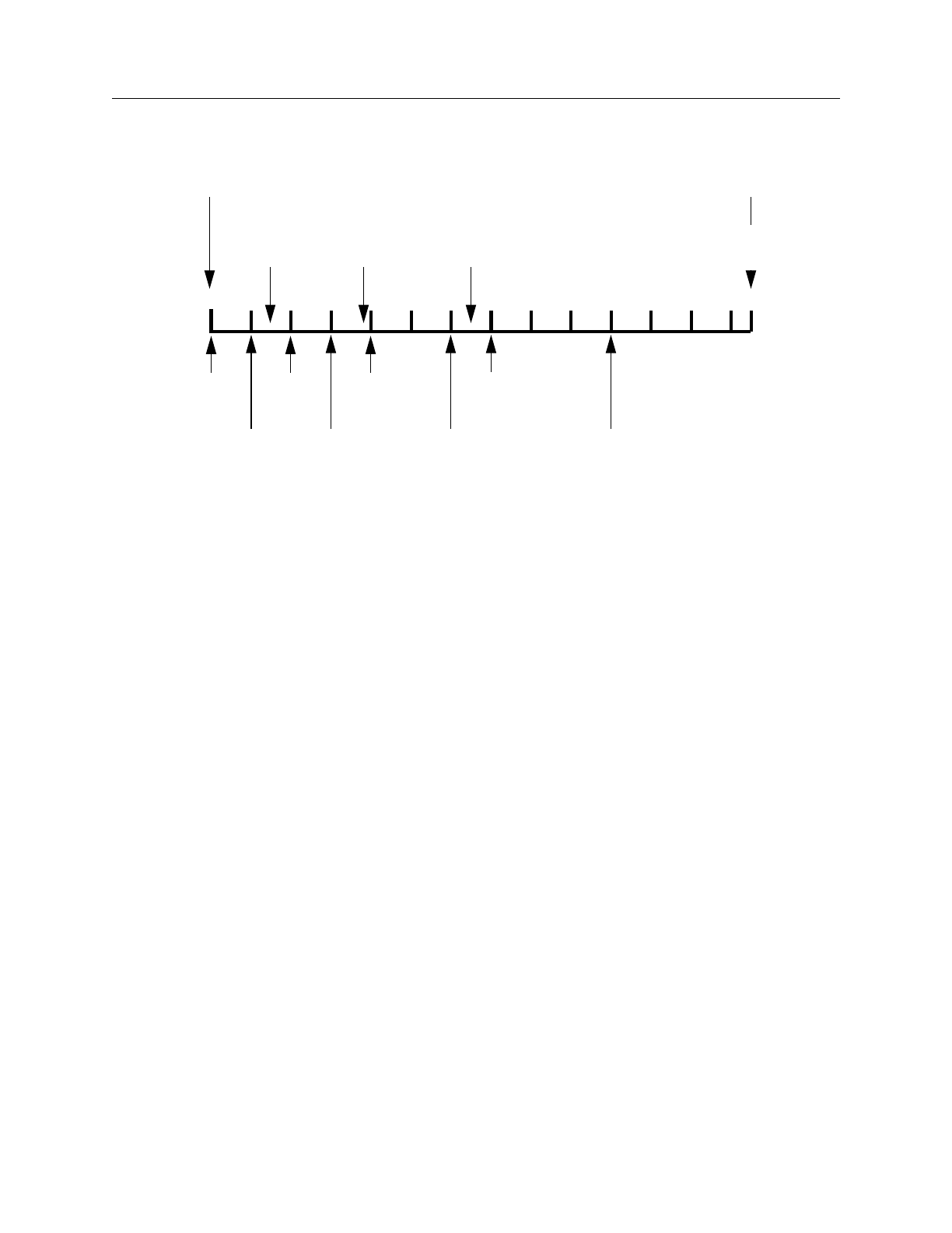
FastScan and FlexTest Reference Manual, V8.6_4
A-34
SET BIDI_FORCE TIME Timing Command Dictionary
Figure A-6 shows when the bidirectional pin forces occur based on this example.
Figure A-6. SET BIDI_FORCE Timing Example
Related Commands
SET PROCEDURE FILE SET SPLIT_BIDI_CYCLE TIME
measure
cycle starts cycle ends
135ns
70ns
100ns0
force force force
20ns 40ns
measure measure
15ns 38ns 65ns
50ns
force
0ns
10ns
bidi_force 30ns
bidi_force 60ns
bidi_force 100ns
bidi_force
measure
135ns

Timing Command Dictionary SET CYCLE
FastScan and FlexTest Reference Manual, V8.6_4 A-35
SET CYCLE
Scope: Sets timing information
Usage
SET CYCLE integer
Description
Extends the non-scan cycle duration to ensure stability without adding extra
timeframes.
FlexTest commonly defines clock pin timing using a test cycle with two
timeframes. In this case, the clock goes active sometime within timeframe 2 and
goes inactive at the end of timeframe 2. The second clock transition coincides
with the input pin forces in the next test cycle, because by default input pin forces
occur at time 0 in the first timeframe. This sometimes creates timing violations,
such as hold time violations in latch-based designs or setup time violations in
multi-edge flip-flop designs.
You can avoid these types of violations by specifying a three-timeframe test cycle.
However, as you increase the number of timeframes in a test cycle, fault
simulation and ATPG process run-times also increase. The SET CYCLE
command provides a solution to this problem. You can use the SET CYCLE
command to specify the period of the test cycle, increasing the time of the last
timeframe, without having to add more timeframes. This command allows the
clock to turn off at the time specified by the last time value of SET FORCE TIME
after which no meaningful activity occurs until the start of the new test cycle.
Note that this timing file command is similar to the PERIOD statement that
FastScan uses in its TIMEPLATE description.
Arguments
•integer
The period you wish to set for the test cycle. You must specify a cycle time
greater than or equal to the last force time in the cycle, to remain consistent
with FlexTest internal simulation.

FastScan and FlexTest Reference Manual, V8.6_4
A-36
SET CYCLE Timing Command Dictionary
Example
The following example shows how a SET CYCLE command can set the period of
a test cycle, eliminating the need to add more timeframes. Assume you entered the
following application commands within a FlexTest session:
//FlexTest application commands
set test cycle 2
setup pin constraints NR 1 0
setup pin strobes 1
add pin constraints CLK SR0 1 1 1
Also assume the timing file contains the following timing commands:
//Timing file commands
SET FORCE TIME 100 200;
SET MEASURE TIME 90 190;
SET SKEW_FORCE TIME “cntrl” 50 150;
SET BIDI_FORCE TIME 70 170;
SET CYCLE 250;
Figure A-7 shows the resulting timing diagram generated for input pin ENABLE,
bidirectional pin ABUS, bidirectional control pin CNTRL, and clock pin CLK.
Figure A-7. SET CYCLE Timing Example
Normally the second timeframe would end at time 200ns. However, specifying
the SET CYCLE command in this manner extends the second timeframe until
0 ns 50 70 90 100 ns 150 200 250 ns
ENABLE
CNTRL
ABUS
CLK
Timeframe 1 Timeframe 2

Timing Command Dictionary SET CYCLE
FastScan and FlexTest Reference Manual, V8.6_4 A-37
time 250. The only event allowed at time 200, which is the original end of the test
cycle, is forcing the clock inactive. The next event, which is the non-return pin
force, occurs at the start of the next test cycle, which is time 250ns.
Note that non-return pins change only once during the test cycle. The “cntrl” pin
could change at either 50 or 150. In this example, it changes at time 50. Likewise,
the bidirectional pins could change at either time 70 or 170. In this case, they
change at time 70.

FastScan and FlexTest Reference Manual, V8.6_4
A-38
SET END_MEASURE_CYCLE TIME Timing Command Dictionary
SET END_MEASURE_CYCLE TIME
Scope: Enables special timing rules checking and sets timing information.
Usage
SET END_MEASURE_CYCLE TIME integer
Description
Ensures that the primary output measure is the last event of the test cycle, and
moves the measure_sco event to the end of the previous test cycle.
Certain tester formats, such as TDL 91, expect all measures to occur at the end of
the tester cycle. However, the scan output pin comparison always occurs in the
shift procedure prior to the shift clock application. The tester should measure scan
output pins in the shift procedure at the end of the test cycle. Therefore, when you
specify this command, the test pattern formatter safely moves the scan output
measure event to the end of the previous cycle.
Unlike the SET SPLIT_MEASURE_CYCLE TIME command, this command
ensures that all test cycles have measure events at the end--without splitting the
original test cycle into two. Note that you can specify only one of the following
commands in a timing file:
•SET SINGLE_CYCLE TIME
•SET SPLIT_BIDI_CYCLE TIME
•SET END_MEASURE_CYCLE TIME
•SET SPLIT_MEASURE_CYCLE TIME
If you place this command in the timing file, the timing rules checker ensures
compliance to the following conditions:
•All output pin strobes occur in the same timeframe.
•The period of all pins equals the end_measure_cycle time.

Timing Command Dictionary SET END_MEASURE_CYCLE TIME
FastScan and FlexTest Reference Manual, V8.6_4 A-39
•The period of all scan test procedures equals the end_measure_cycle time
or is the end_measure_cycle time multiplied by the number of cycles in the
procedure.
•The end_measure_cycle time is greater than the strobe time and less than or
equal to the test cycle period.
•No input pin forces occur after the end_measure_cycle time.
•For each scan test procedure, each clock pin force event corresponds to the
pair of force times in the timing file.
•For each scan test procedure, each force event on a non-clock pin
corresponds to the force time in the timing file.
•The measure_sco time in the shift procedure, which defines the scan output
measure time, is zero.
In some tester formats (such as UTIC), you can specify a separate timing
definition for the shift procedure. In this case, the timing rules checker does not
consider the shift procedure for compliance with the constraints listed earlier.
Arguments
•integer
An integer time value specifying the final test cycle length. This number must
match the period of the shift procedure.
Examples
The following example specifies a timing definition that satisfies all the
constraints described previously.
// FlexTest Application Commands
set test cycle 2;
setup pin costraints NR 1 0;
add pin constraints SR0 clk_a 1 1 1;
setup pin strobes 2;
//FlexTest Timing File
SET TIME SCALE 1 ns;

FastScan and FlexTest Reference Manual, V8.6_4
A-40
SET END_MEASURE_CYCLE TIME Timing Command Dictionary
SET END_MEASURE_CYCLE TIME 500;
SET FORCE TIME 300 400;
SET MEASURE TIME 200 350;
SET CYCLE TIME 500;
SET PROCEDURE FILE “g1” “design.g1”;
PROC SHIFT =
FORCE_SCI 0;
MEASURE_SCO 0;
FORCE clk_a 1 300;
FORCE clk_a 0 400;
PERIOD 500;
END;
Related Commands
SET SINGLE_CYCLE TIME SET SPLIT_BIDI_CYCLE TIME

Timing Command Dictionary SET FIRST_FORCE TIME
FastScan and FlexTest Reference Manual, V8.6_4 A-41
SET FIRST_FORCE TIME
Scope: Sets timing information
Usage
SET FIRST_FORCE TIME integer
Description
Sets input pin force time for the first timeframe.
By default, pin forces for all unspecified pins occur at time 0 in the first
timeframe. This command lets you specify a later time for the first input pin force.
Note that this timing file command is similar to the INIT_FORCE_PI statement
that FastScan uses in its TIMEPLATE description.
Arguments
•integer
The first force time for all input pins in the first timeframe.
Examples
The following timing file command changes the default first force time from 0ns
to 5ns.
SET FIRST_FORCE TIME 5;
Related Commands
SET PROCEDURE FILE

FastScan and FlexTest Reference Manual, V8.6_4
A-42
SET FORCE TIME Timing Command Dictionary
SET FORCE TIME
Scope: Sets timing information
Usage
SET FORCE TIME time_value_list
Description
Sets input pin force time for each timeframe.
The SET FORCE TIME command lets you specify force times for all input pins
of a device under test during each timeframe in a test cycle. If you need to specify
unique force times for a particular pin, you must use the SET SKEW_FORCE
TIME command. If your design contains bidirectional pins, you should also
specify the SET BIDI_FORCE TIME command.
The SET FORCE TIME command accomplishes two tasks: it specifies the pin
force times and establishes the timeframe boundaries. By default, input pin forces
occur at the start of each timeframe, and the start of one timeframe and the end of
the previous timeframe occur at the same time. Thus, while this command
establishes the pin force times, it also establishes the timeframe boundaries,
because the force times occur at these boundaries.
The last value in the time_value_list usually specifies the ending time of the test
cycle, which equates to time 0 of the next test cycle. However, you can use the
SET CYCLE command to extend the last timeframe, while still allowing the clock
off event to occur at the specified force time. For example, assume the last force
value is 150, and you specify 200 as the test cycle length with SET CYCLE. In
this case, the force event at time 150 would force the clock off, and then no other
events would occur until the start of the next test cycle which is time 200.
You must ensure that the force time occurs before the measure time in each
timeframe. If you only specify the SET FORCE TIME command or the SET
MEASURE TIME command but not both of these commands within your timing
file, FlexTest assigns both the force and measure events to the same time.
Note that this timing file command is similar to the FORCE_PI statement that
FastScan uses in its TIMEPLATE description.

Timing Command Dictionary SET FORCE TIME
FastScan and FlexTest Reference Manual, V8.6_4 A-43
Arguments
•time_value_list
A set of time values indicating when the input pin forces should occur. The
number of list values must equal the number of timeframes in the test cycle, as
specified by the Set Test Cycle application command.
In the first timeframe, input pin forces always either occur at 0 or a time
specified by the SET FIRST_FORCE TIME command. So, the time values
you specify using this command establish the force times for the remaining
timeframes in the test cycle. Each time value specified corresponds to the next
timeframe. For example, the first specified time value corresponds to the start
of the second timeframe and so on.
Examples
Assuming the test cycle contains four timeframes, the following example specifies
input pin forces at 0, 20, 40, and 70ns after the start of the test cycle.
SET FORCE TIME 20 40 70 150;
Figure A-8 shows when the input pin forces occur based on this example.
Figure A-8. SET FORCE Timing Example
As shown, the first test cycle’s forces occur at time 0, 20, 40, and 70ns. The time
of 150 establishes the end of the test cycle. In the second test cycle, forces would
occur at time 150 plus the specified offsets; that is, at time 150 (150+0), 170
(150+20), 190 (150+40), and 220ns (150+70).
Force times for all unspecified pins
cycle starts cycle ends
20NS 70NS 150NS
40NS
0NS


Timing Command Dictionary SET MEASURE TIME
FastScan and FlexTest Reference Manual, V8.6_4 A-45
SET MEASURE TIME
Scope: Sets timing information
Usage
SET MEASURE TIME time_value_list
Description
Sets output pin measure time for each timeframe.
The SET MEASURE TIME command lets you specify measure times for all
output pins of a device during each timeframe in a test cycle. The measure time in
a timeframe must occur before the force, bidirectional force, and skew force times
in the next timeframe.
If you only specify the SET FORCE TIME command or the SET MEASURE
TIME command but not both of these commands within your timing file, FlexTest
assigns both the force and measure events to the same time.
Note that this timing file command is similar to the MEASURE_PO statement
that FastScan uses in its TIMEPLATE description.
Arguments
•time_value_list
A set of time values indicating when the output pin measures should occur.
The number of list values must equal the number of timeframes in the test
cycle, as specified by the Set Test Cycle application command description in
Chapter 2. These time values must occur between the force in one timeframe
and the force in the next timeframe.
Example
The following timing file command specifies output pin measures at 15, 38, 65,
and 135ns after the start of the test cycle.
SET MEASURE TIME 15 38 65 135;

FastScan and FlexTest Reference Manual, V8.6_4
A-46
SET MEASURE TIME Timing Command Dictionary
Figure A-9 shows when the output pin measures occur based on this example.
Figure A-9. SET MEASURE Timing Example
You could use these measure times in conjunction with the force times specified
in the SET FORCE TIME example. In the first 150ns test cycle, the measure times
occur at 15, 38, 65, and 135ns. In the second test cycle, the measure times occur at
150 plus the specified offsets; that is, 165, 188, 215, and 285ns.
Related Commands
SET END_MEASURE_CYCLE
TIME SET PROCEDURE FILE
SET SPLIT_BIDI_CYCLE TIME
Measure times (for test cycle 1)
cycle starts cycle ends
15NS 38NS 65NS 135NS
0NS 150NS

Timing Command Dictionary SET PROCEDURE FILE
FastScan and FlexTest Reference Manual, V8.6_4 A-47
SET PROCEDURE FILE
Scope: Sets timing information
Usage
SET PROCEDURE FILE {“scan_group_name”“filename”}...
Description
Specifies which test procedure files to use during pattern save.
ATPG requires the test procedure file to contain the proper sequence of events,
but does not require it to specify the real timing information. However, simulators
and ATE do require this information. Thus, you must edit your test procedure files
to include real timing information after you run the ATPG process. You then use
the SET PROCEDURE FILE command to specify the proper test procedure file.
Note that when you modify the test procedure file, you can only add real timing
values. You cannot delete, reorder, or change any statements--including adding
break or break_repeat statements.
This command lets you specify multiple scan groups and their associated test
procedure files. If you use this command without specifying the scan group name
and test procedure file name, the tool uses the original test procedure file to update
the time values for all scan groups.
Arguments
•“scan_group_name”
A quoted string that specifies the name of the scan group to which the test
procedure file applies. You must surround this argument in double-quotes.
•“filename”
A quoted string that specifies the name of the test procedure file for the
specified scan group. You must surround this argument in double-quotes.
Examples
The following timing file command specifies to use the timing information from
the test procedure file design.g1 for the g1 scan group.
SET PROCEDURE FILE “g1” “design.g1”;


Timing Command Dictionary SET SINGLE_CYCLE TIME
FastScan and FlexTest Reference Manual, V8.6_4 A-49
SET SINGLE_CYCLE TIME
Scope: Enables special timing rules checking
Usage
SET SINGLE_CYCLE TIME integer
Description
Enables timing rules checking to ensure a single time exists for both scan and non-
scan test cycles.
Some tester formats, such as Compass Scan, TDL 91, and FTDL-E, allow only a
single timing definition for each tester cycle. As a result, both the scan test
procedure and the non-scan cycle must use the same timing. The SET
SINGLE_CYCLE TIME command enables the ASICVector Interfaces (AVI)
functionality to perform this timing check.
If you place this command in the timing file, the timing rules checker ensures
compliance to the following conditions:
•The period of all scan test procedures equals the single_cycle time or a
multiple of the number of cycles in the test procedure.
•The period of all the pins equals the single_cycle time.
•For each scan test procedure, each force event time on a clock pin
corresponds to the clock timing specified in the application timing
commands.
•For each scan test procedure, each force event on a non-clock pin
corresponds to the force time specified in the application timing commands.
Note that you can specify only one of the following commands in a timing file:
•SET SINGLE_CYCLE TIME
•SET SPLIT_BIDI_CYCLE TIME
•SET END_MEASURE_CYCLE TIME

FastScan and FlexTest Reference Manual, V8.6_4
A-50
SET SINGLE_CYCLE TIME Timing Command Dictionary
•SET SPLIT_MEASURE_CYCLE TIME
Arguments
•integer
Time value that specifies both the scan and non-scan cycle duration. This
number must match the period of the shift procedure.
Examples
The following example satisfies all the timing constraints listed in the command
description. Note that the shift clock timing and the capture clock timing are
identical.
Assume you have entered the following FlexTest application commands:
//FlexTest commands
set test cycle 2
setup pin constraints NR 1 0
add pin constraints clk_a SR0 1 1 1
setup pin strobes 1
The corresponding timing file contains the following commands:
// FlexTest timing file
SET TIME SCALE 1 ns;
SET SINGLE_CYCLE TIME 1000; //matches shift period
SET FORCE TIME 500 600;
SET MEASURE TIME 400 550;
SET CYCLE 1000;
SET PROCEDURE FILE “g1” “design.g1”;
The design.g1 test procedure file contains the following shift procedure for scan
group g1:
PROC SHIFT =
FORCE_SCI 0;
MEASURE_SCO 400;
FORCE clk_a 1 500;
FORCE clk_a 0 600;
PERIOD 1000;
END;


FastScan and FlexTest Reference Manual, V8.6_4
A-52
SET SKEW_FORCE TIME Timing Command Dictionary
SET SKEW_FORCE TIME
Scope: Sets timing information
Usage
SET SKEW_FORCE TIME “pin_name” time_value_list
Description
Specifies input pin force time for particular pins in each timeframe.
While the SET FORCE TIME command specifies force times for all pins, the SET
SKEW_FORCE TIME command lets you specify unique force times for a
particular input pin for each timeframe in a test cycle.
Note that this timing file command is similar to the SKEW_FORCE_PI statement
that FastScan uses in its TIMEPLATE description.
Arguments
•“pin_name”
The name of a primary input pin, which must be enclosed in double-quotes, for
which you want to specify unique timing.
•time_value_list
A set of time values indicating when the specified input pin forces should
occur. Each skew force time should occur prior to the measure time in every
timeframe.
The number of list values must equal the number of timeframes in the test
cycle, as specified by the Set Test Cycle application command. Unlike the
values in the SET FORCE TIME command, the position of the time values
with the SET SKEW_FORCE TIME command correspond to the same
timeframe. For example, the first specified time value occurs in the first
timeframe.

Timing Command Dictionary SET SKEW_FORCE TIME
FastScan and FlexTest Reference Manual, V8.6_4 A-53
Examples
The following example shows a timing file that includes the SET BIDI_FORCE
TIME command used with the SET FORCE TIME and SET MEASURE TIME
commands. Assume the test cycle contains four timeframes.
SET FORCE TIME 20 40 70 150;
SET MEASURE TIME 15 38 65 135;
SET SKEW_FORCE TIME “cntrl” 8 25 55 90;
Figure A-10 shows when the “cntrl” pin forces occur based on this example.
Figure A-10. SET SKEW_FORCE Timing Example
Related Commands
SET END_MEASURE_CYCLE
TIME SET PROCEDURE FILE
Force “cntrl” pin
cycle starts cycle ends
25NS 90NS 150NS
55NS
8NS
0NS

FastScan and FlexTest Reference Manual, V8.6_4
A-54
SET SPLIT_BIDI_CYCLE TIME Timing Command Dictionary
SET SPLIT_BIDI_CYCLE TIME
Scope: Enables special timing rules checking
Usage
SET SPLIT_BIDI_CYCLE TIME integer
Description
Specifies the period for test procedures and splits the non-scan cycle before the
force or bidi_force time.
Certain testers formats, such as UTIC and Compass Scan, do not allow state
changes on both input pins and bidirectional pins in a single tester cycle. In this
case, you must split each non-scan cycle into two tester cycles. The SET
SPLIT_BIDI_CYCLE TIME command enables the ASICVector Interfaces (AVI)
functionality to split the non-scan test cycle into two tester cycles when writing
patterns.
If you place this command in the timing file, the timing rules checker ensures
compliance to the following conditions:
•The period of all pins is twice that of the split_bidi_cycle time.
•The period of all scan test procedures equals the split_bidi_cycle time
multiplied by the number of cycles in the test procedure.
•The timing file contains the SET BIDI_FORCE TIME command to specify
bidirectional pin force times.
•All bidirectional pins have the same offset time.
•The split_bidi_cycle time is greater than the force time and less than or
equal to the bidirectional force time for each bidirectional pin.
•For each scan test procedure, each force event time on a clock pin
corresponds to the pair of force times specified in the timing file.
•For each scan test procedure, each force event on a non-clock pin
corresponds to the force time specified in the timing file.

Timing Command Dictionary SET SPLIT_BIDI_CYCLE TIME
FastScan and FlexTest Reference Manual, V8.6_4 A-55
Note that you can specify only one of the following commands in a timing file:
•SET SINGLE_CYCLE TIME
•SET SPLIT_BIDI_CYCLE TIME
•SET END_MEASURE_CYCLE TIME
•SET SPLIT_MEASURE_CYCLE TIME
Arguments
•integer
The time value at which to split the non-scan test cycle. This number must
match the period of the shift procedure.
Examples
The following example shows a timing definition satisfying all the conditions
specified in the command description. Note that the shift clock timing and the
capture clock timing are compatible. Also, note that the split_bidi_cycle time is
greater than the force time and less than the bidi_force time in the first timeframe
(0 < 500 < 550).
//FlexTest application commands
set test cycle 2;
setup pin constraints NR 1 0;
add pin constraints clk_a SR0 1 1 1;
setup pin strobes 1;
//FlexTest Timing file
SET TIME SCALE 1 ns;
SET SPLIT_BIDI_CYCLE TIME 500; //matches shift period
SET FORCE TIME 800 900;
SET BIDI_FORCE TIME 550 825;
SET MEASURE TIME 700 850;
SET CYCLE TIME 1000;
SET PROCEDURE FILE “g1” “design.g1”;
//Test procedure file for FlexTest
PROC SHIFT =
FORCE_SCI 0;


Timing Command Dictionary SET SPLIT_MEASURE_CYCLE TIME
FastScan and FlexTest Reference Manual, V8.6_4 A-57
SET SPLIT_MEASURE_CYCLE TIME
Scope: Enables special timing rules checking
Usage
SET SPLIT_MEASURE_CYCLE TIME integer
Description
Specifies the period for test procedures and splits the non-scan cycle at the
measure time.
Certain tester formats, such as TDL 91, expect all measures to occur as the last
event in the tester cycle. However, the scan output pin comparison always occurs
in the shift procedure prior to the shift clock application. The tester should
measure scan output pins in the shift procedure at the end of the previous cycle.
Therefore, when you specify this command, the test pattern formatter safely
moves the measure_sco event to be the last event of the previous cycle.
This command also causes the application to split the non-scan test cycle into two
test cycles. The application splits the test cycle only if the measure_po event does
not occur at the end of the test cycle.
If you place this command in the timing file, the timing rules checker ensures
compliance to the following conditions:
•All output pin strobes occur in the same timeframe.
•At least one input pin force occurs in a timeframe after the timeframe in
which output pin strobes occur.
•The period of all pins is twice that of the split_measure_cycle time.
•The period of all scan test procedures equals the split_measure_cycle time
or is the split_measure_cycle time multiplied by the number of test cycles
in the test procedure.
•The split_measure_cycle time is greater than the measure time and less than
or equal to the force time for each pin.

FastScan and FlexTest Reference Manual, V8.6_4
A-58
SET SPLIT_MEASURE_CYCLE TIME Timing Command Dictionary
•For clock pins, each test procedure force event time corresponds to the pair
of pin force times. Note that the tool subtracts the split_measure_cycle from
the force times before this check.
•Each test procedure force event on a non-clock pin corresponds to the force
time for all pins.
•The measure_sco time in the shift procedure, which defines when the scan
output measure should occur, is zero.
Note that you can specify only one of the following commands in a timing file:
•SET SINGLE_CYCLE TIME
•SET SPLIT_BIDI_CYCLE TIME
•SET END_MEASURE_CYCLE TIME
•SET SPLIT_MEASURE_CYCLE TIME
Arguments
•integer
The time value at which to split the non-scan cycle. This number must match
the shift procedure period.
Examples
The following FlexTest example shows a timing definition that satisfies all the
conditions specified in the command description. Note that the shift clock timing
is compatible with the capture clock timing. Also, note that the
split_measure_cycle time is greater than the measure time in the first timeframe
and less than the force time in the second timeframe (400 < 500 < 800).
//FlexTest application commands
add clocks 0 clk
add clocks 1 clear
set test cycle 2
add pin constraints CLK SR0 1 1 1
add pin constraints CLEAR SR1 1 1 1
setup pin strobes 1

Timing Command Dictionary SET SPLIT_MEASURE_CYCLE TIME
FastScan and FlexTest Reference Manual, V8.6_4 A-59
save pat pat.split.titdl -titdl counter.flx.time.split
//Timing file “counter.flx.time.split” commands
set time scale 1 ns;
set split_measure_cycle time 250;
set force time 300 400;
set measure time 200 350;
set cycle time 500;
set procedure file "g1" "counter.ti.g1.split";
//Test procedure file “counter.ti.g1.split”
proc shift =
measure_sco 0;
force_sci 0;
force CLK 1 50;
force CLK 0 150;
period 250;
end;
proc load_unload =
force SE 1 0;
force CLEAR 1 150;
force CLK 0 150;
apply shift 10 250;
period 250;
end;
Related Commands
SET SINGLE_CYCLE TIME SET SPLIT_BIDI_CYCLE TIME

FastScan and FlexTest Reference Manual, V8.6_4
A-60
SET STROBE_WINDOW TIME Timing Command Dictionary
SET STROBE_WINDOW TIME
Scope: Enables special timing rules checking
Usage
SET STROBE_WINDOW TIME integer
Description
Specifies the strobe window width.
Some tester formats can measure primary outputs (POs) at the exact time that you
specify with the SET MEASURE TIME statement in the timeplate. However,
other tester formats, such as UTIC, require that output measurements occur during
a specified window of time (strobe window). You can set this strobe window
using the SET STROBE_WINDOW TIME command.
If you specify this command in the timing file, the timing rules checker ensures
that the difference between the measure time in a timeframe and the force time in
the next timeframe equals or exceeds the strobe_window time. This is to ensure
that the outputs remain stable during the strobe window. Note that for some
formats, such as TSSI WGL, this command changes the strobe window in the
output file.
Arguments
•integer
The length of time after the measure event, in which no event can occur.
Example
The following example illustrates a modified strobe window:
//FlexTest application commands
set test cycle 2;
setup pin constraints NR 1 0;
add pin constraints clk_a SR0 1 1 1;
setup pin strobes 1;

Timing Command Dictionary SET STROBE_WINDOW TIME
FastScan and FlexTest Reference Manual, V8.6_4 A-61
//Timing file commands
SET TIME SCALE 1 ns;
SET STROBE_WINDOW TIME 50;
SET FORCE TIME 800 900;
SET MEASURE TIME 400 850;
SET CYCLE TIME 1000;
Figure A-11 shows the output strobe window for this example.
Figure A-11. SET STROBE_WINDOW Timing Diagram
Related Commands
None.
0ns
CLK
X
PIs
100ns
Strobe Window
500ns
Test Cycle
POs XXX
X
450
400
(SET MEASURE TIME can occur anytime within this window)

FastScan and FlexTest Reference Manual, V8.6_4
A-62
SET TIME SCALE Timing Command Dictionary
SET TIME SCALE
Scope: Sets timing information
Usage
SET TIME SCALE number unit
Description
Sets the time scale and unit.
FlexTest applies the timing scale and unit you specify in the timing file to the test
procedure file and timeplates. If you do not specify this command, the default
value for the timing scale is 1000ns.
Arguments
•number
The factor multiplied by all time values to get the actual time values. The
number argument can be any real number, the default being 1000.
•unit
The time scale unit, such as ns (the default), ps, ms, or us.
Examples
The following timing file command sets the time scale to 1 nanosecond.
SET TIME SCALE 1 ns;
Related Commands
SET PROCEDURE FILE

FastScan and FlexTest Reference Manual, V8.6_4 B-1
Appendix B
FlexTest WDB Translation Support
Mentor Graphics provides a shell command utility called wdb2flex to translate
Mentor Graphics waveform databases (WDBs) to FlexTest table format patterns.
This gives FlexTest the ability to act as a fault simulator for existing patterns. The
benefits of using FlexTest in this manner are:
1. FlexTest performs fault simulation on an existing pattern set. Because it
does not consider timing, FlexTest is much more efficient than QuickFault
II.
2. FlexTest uses the existing patterns to initialize the circuit, giving some
initial fault coverage, and then performs ATPG on the remaining faults.
This can result in smaller test pattern sets and shorter run times.
Invoking wdb2flex
To invoke the wdb2flex utility for designs without bidirectional pins:
wdb2flex
ctrl_file forces_wdb
[
results_wdb
] [-O
output_file
]
To invoke the wdb2flex utility for designs with bidirectional pins
wdb2flex
ctrl_file forces_wdb results_wdb
[-O
output_file
]
The utility names the default output file table.flex, although you can rename it to a
different output file name by using the -O option. The control file, which the
utility uses to set up the sampling of the waveforms in the forces WDB, is a
required argument, as is the forces_wdb option. The results_wdb option, which
allows FlexTest to perform output comparisons, is optional only if the design
contains no bidirectional pins. If there are any bidirectional pins in the design,
then results_wdb is a required argument. The wdb2flex utility recognizes
bidirectional pin waveforms because they appear in both the forces and results

FastScan and FlexTest Reference Manual, V8.6_4
B-2
Control File FlexTest WDB Translation Support
WDB. The strength of these forces and results waveforms determines whether the
utility treats a bidirectional pin as an input or output. For specific information
about how wdb2flex resolves the state of bidirectional pins refer to page B-8.
Control File
The purpose of the control file is to set up sampling of the waveforms in the forces
WDB. To achieve this, you must specify information about the circuit timing. For
timing purposes, wdb2flex considers a clock to be a signal that changes twice in a
test cycle. The Add Pin Constraints command uses this same definition. On the
other hand, the Add Clocks command of DFTAdvisor, FastScan, and FlexTest
defines a clock as any signal that can change the state of a sequential element.
The utility supports the following commands in the control file.
SET CYcle Time number
The Set Cycle Time command sets the test cycle time. The utility takes a sample
every cycle. Number is the cycle time in nanoseconds, which generally equals the
clock period of the stimulus. If the circuit contains multiple clocks, you would
typically make the cycle time equivalent to the period of the fastest clock.
SETup INput Strobes number
The Setup Input Strobes command sets the default strobe point for all input
waveforms. Typically, number would be 0. However, if the primary inputs change
at different times, you should specify a time at which the inputs are no longer
changing.
SETup OUtput Strobes number
Note
All the timing information you specify with these commands
should be relative, not absolute.

FlexTest WDB Translation Support Control File
FastScan and FlexTest Reference Manual, V8.6_4 B-3
The Setup Output Strobes command sets the default strobe point for all output
waveforms. Keeping the test cycle in mind, you should specify a time before the
clock is active, but after the output data is stable. Typically, you should not strobe
at the clock edges if the design contains latches, because timing problems could
result.
ADD INput Strobes number input_list
The Add Input Strobes command changes the sampling time of one or more
specific inputs from the default value to the specified number. Typically, you
would use Setup Input Strobes to set the strobe time for all inputs and only use this
command if you had a special case that required strobing a certain pin at a
different time.
ADD OUtput Strobes number output_list
The Add Output Strobes command changes a particular output sampling time
from the default to the specified number. Typically, you would use Setup Output
Strobes to set the strobe time for all outputs and only use this command if you had
a special case that required strobing a certain pin at a different time.
ADD INput Clocks format strobe1 strobe2 input_list
The Add Input Clocks command sets the clocks’ format and strobe points. The
available format literals are R0, R1, SR0, SR1. The strobe points sample the
waveform and perform error checking. Strobe1 must occur when the clock is on
and strobe2 must occur when the clock is off. For the SR0 and SR1 formats, if the
two strobe sample points have different values, there is a pulse in that cycle. The
utility error checks all formats to make certain that the pulse matches the format. It
issues a warning if it encounters any inconsistencies. Thus, the stimulus generated
in FlexTest table format is guaranteed to be correct. For instance, if the input
stimulus for a R0 waveform is missing a pulse in a cycle, FlexTest requires the
translator to insert one.
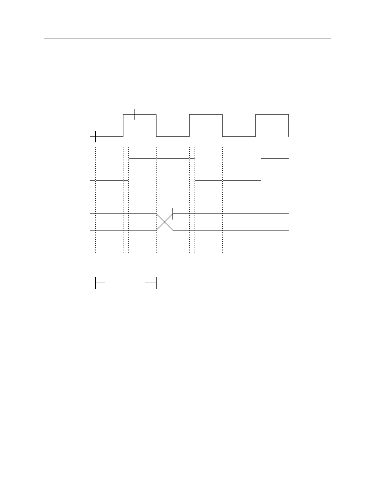
FastScan and FlexTest Reference Manual, V8.6_4
B-4
Example FlexTest WDB Translation Support
Example
This example assumes that Figure B-1 shows the behavior of two of the design’s
clocks.
Figure B-1. Example WDB2FLEX Circuit Timing Example
Here is an example of how to invoke wdb2flex from the shell to translate a Mentor
Graphics waveform database to FlexTest table format which you can then use as
an external pattern source for a FlexTest run:
shell> $MGC_HOME/bin/wdb2flex -O flex.stim sample_commands
forces.wdb results.wdb
CLK1
CLK2
DATA
900
980 1000 1050 1130
1134984
1080
900
Time
Frames 123
Test Cycle
150ns

FlexTest WDB Translation Support Example
FastScan and FlexTest Reference Manual, V8.6_4 B-5
You can also invoke wdb2flex from the FlexTest command line to perform the
same translation by using the System command as shown here:
SYStem $MGC_HOME/bin/wdb2flex -O flex.stim sample_commands
forces.wdb results.wdb
The control file, called sample_commands, contains the following commands:
SET CYcle Time 150
SETup INput Strobes 30
SETup OUtput Strobes 145
ADD INput Clocks SR0 100 150 CLK1
ADD INput Strobe 100 CLK2
The Set Cycle Time command sets the test cycle to 150ns, the period of the fastest
clock. In this instance, wdb2flex considers CLK1 to be the only clock in this
circuit, because the utility’s definition of a clock is a signal that changes twice in a
test cycle. With a cycle time of 150ns, the only signal that changes twice is CLK1.
Figure B-1 shows that the timing starts at 900ns, which is the start of the 7th test
cycle. Since the data is stable 30ns after the beginning of each cycle, the input
strobe time is at 30ns. The output strobe time should be at the time when all output
values are stable. Normally, this happens at the end of each test cycle, therefore,
the output strobe time is at 145ns. The first clock strobe occurs at 1000ns and the
second clock strobe occurs at 1050ns. Thus, if you specify relative timing, you
should strobe the clock at 100ns after the start of the test cycle and again at 150ns,
which is the end of the test cycle. The Add Input Clocks command specifies that
the signal CLK1 is a clock with a format of SR0 and strobe times of 100 and
150ns. Because CLK2 acts as a unique input, an Add Input Strobe command
specifies to strobe this signal at 100ns.
To set up the test cycle and pin constraints for this circuit in the Setup mode in
FlexTest, enter the following:
SET TEst Cycle 3
ADD PIn Constraints SR0 1 1 1 CLK1
ADD PIn Constraints SR0 2 2 2 CLK2

FastScan and FlexTest Reference Manual, V8.6_4
B-6
Using wdb2flex Effectively FlexTest WDB Translation Support
Given this timing information, FlexTest will need a test cycle with three
timeframes in order to successfully simulate all the necessary events. The first
timeframe is from 900-980ns, when both clocks are off. The second timeframe is
from 980-984ns, when CLK1 is on. The third timeframe is from 984-1050ns,
when both clocks are on.
To run the resulting pattern file in FlexTest, do the following if you are in the
Atpg, Fault, or Good system modes:
SET PAttern Source External flex.stim
RUN
Using wdb2flex Effectively
You need to exercise great care in creating a waveform database that FlexTest can
use effectively. You can use wdb2flex to translate many, but not all, waveform
databases into effective test patterns. The main restriction is that the stimulus
should be periodic. Perform the following steps to obtain the optimum control file
for a particular waveform database.
1. Find the smallest length of time that satisfies step 2. This is typically the
period of the fastest clock waveform in the waveform database. Use this as
the cycle time in the control file.
2. Scan the waveforms at all pins to ensure that a regular input pin changes at
most once per period, and that a clock input pin either does not change or
changes twice per cycle. This defines the test cycle for FlexTest and
wdb2flex.
3. For each input pin, find the relative time in the period at which it changes.
This defines the input strobe time of each input pin. If there is a time within
a test cycle after which all primary inputs stabilize, use this time to strobe
all primary input pins using the Setup Input Strobe command. In general,
you should minimize the number of points at which you strobe all inputs by
careful selection of those strobe points.

FlexTest WDB Translation Support Using wdb2flex Effectively
FastScan and FlexTest Reference Manual, V8.6_4 B-7
4. For each output pin, find the relative time in the period at which the output
is stable for all test cycles. This defines the output strobe time of each
output pin. This can be a point at the middle of the test cycle, after changing
all primary inputs, but before the application of any clock pulses. This time
can also be at the end of the test cycle, after all input and output waveforms
stabilize. In general, you should minimize the number of points at which
you strobe all outputs by careful selection of those strobe points.
5. For each clock pin, find the relative time in the period at which the clock
goes active. This defines the first strobe time of the clock pin. Find also the
relative time in the period after which the clock remains in the off state for
each clock pin. This defines the second strobe time for the clock pin. Clock
pins with an off state of 0 should have an SR0 or R0 format. Clock pins
with an off state of 1, should have an SR1 or R1 format. You should use
SR0 and SR1 formats whenever possible. You should use R0 or R1 timing
waveforms only if your design requires specification of a free-running
clock in every test cycle, regardless of the contents of the waveform
database. In general, you should minimize the number of strobe points for
all clock pins by careful selection of the strobe points.
For the most effective use of wdb2flex on designs using bidirectional pins, you
must meet the following conditions:
•If the design contains bidirectional pins, wdb2flex requires both the forces
(input) and results (output) waveform databases. The wdb2flex utility treats
a pin as a bidirectional only if it’s waveform appears in both the forces and
results waveform databases. The utility creates one pattern table after
resolving the states of the bidirectional pins from the forces and results
waveform databases. If you violate this condition by only providing the
forces waveform database, all bidirectional pins will always have an input
direction, causing bus contention during FlexTest simulation.
•When you supply the results waveform database to wdb2flex, ensure that it
contains only bidirectional and output waveforms. If you violate this
condition, wdb2flex gives error messages about the inconsistent state of
primary input pins.

FastScan and FlexTest Reference Manual, V8.6_4
B-8
Using wdb2flex Effectively FlexTest WDB Translation Support
•wdb2flex resolves the state of bidirectional pins as either input or output
based on the state of the forces and results waveform associated with the
pin. If the forces waveform has a weak strength, the bidirectional is treated
as an output. If the results waveform has a weak strength, the bidirectional
is treated as an input. If neither forces nor results waveforms have a weak
strength and have the same logic values, the utility assumes wired behavior
and treats the bidirectional as an output. If none of the above conditions
prevail, the bidirectional is neither measured nor driven.
To ensure that the results of a QuickSim II simulation correspond with that of
FlexTest, the FlexTest test cycle should correspond to the wdb2flex control file.
You can set up the test cycle using the following steps and the example timing
illustration in Figure B-2:
1. Calculate the number of timeframes in the FlexTest test cycle. The number
should equal the sum of the control file input strobe times and clock strobe
times.
For the example in Figure B-2, if all inputs strobe at 75ns (time t1), all
clocks strobe active at 105ns (time t2), and all clocks strobe for the off-state
at 205ns (time t3), then there should be three timeframes in the test cycle.
The first timeframe (frame 0) corresponds to the time 0—105ns (t1,t2), the
second timeframe (frame 1) corresponds to the time 105—205ns (t2,t3) and
the third timeframe (frame 2) corresponds to the time 205—250ns (t3,
period). The time from 0—75ns is not considered since the stable output is
strobed at 95ns and all input events happen before 75ns.
2. Calculate the timeframe associated with each strobe time. In FlexTest,
when a force event and strobe event occur in the same timeframe, the strobe
event happens before the force event in that timeframe.
3. For all input pins, set up non-return pin constraints with an offset value
equal to one less than the timeframe at which the pin changes state. For the
example in Figure B-2, you would enter the following to indicate that the
offset value is 0; all inputs change at the first timeframe:
setup pin constraints nr 1 0
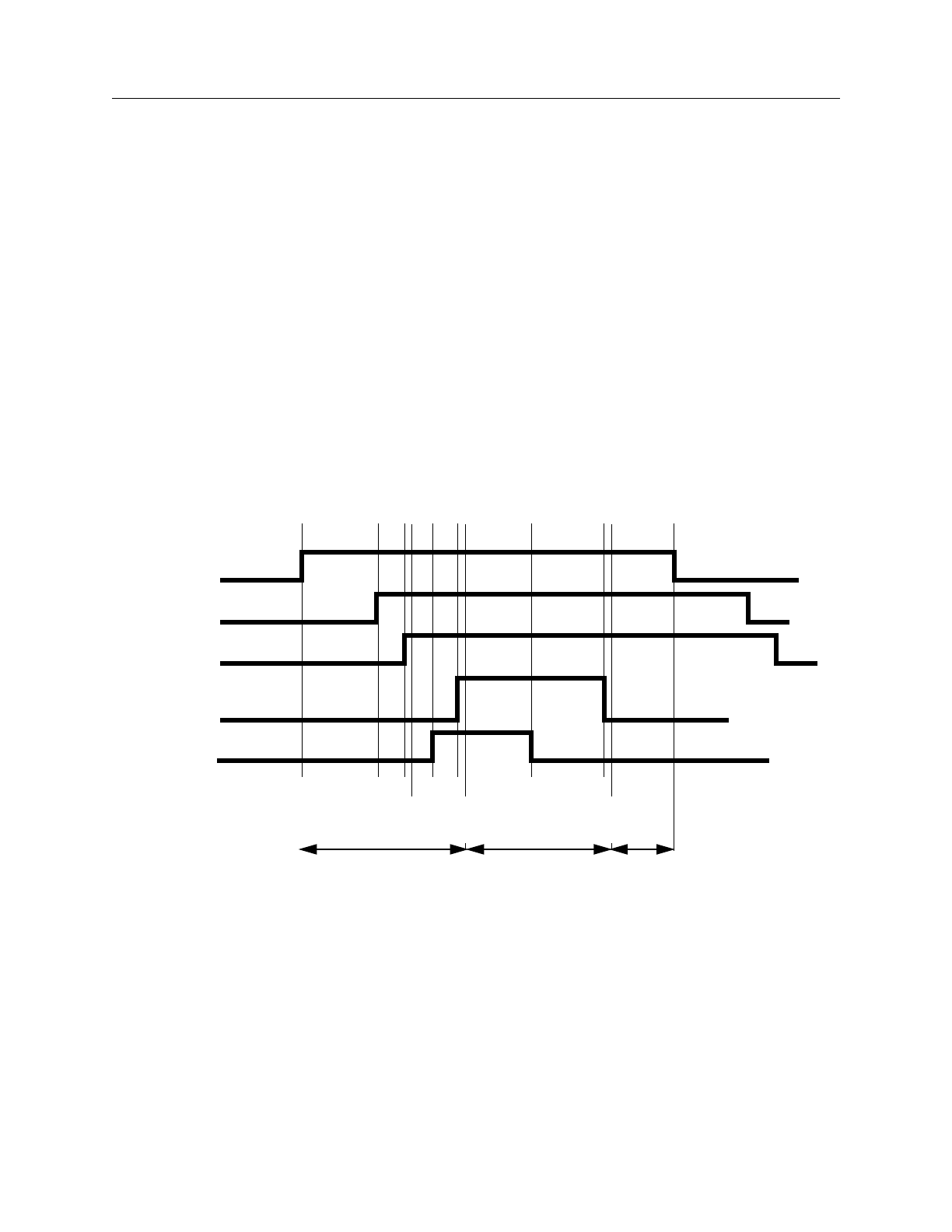
FlexTest WDB Translation Support Using wdb2flex Effectively
FastScan and FlexTest Reference Manual, V8.6_4 B-9
4. For each clock pin, set up return pin constraints corresponding to the
control file (SR0, SR1, R0, R1), with an offset value equal to the timeframe
at which the clock goes active. The pulse width should correspond to the
difference between the timeframe at which the clock goes inactive and the
timeframe at which the clock goes active.
For the example in Figure B-2, you would enter the following to indicate
that CLK has an offset of 0 and a width of 1.
add pin constraints clk sr0 1 0 1
5. For all output pins, specify the strobe timeframe corresponding to the strobe
time in the control file. For the example in Figure B-2, you would enter the
following:
setup pin strobes 1
Figure B-2. Detailed Pin Timing
ENABLE
ABUS
CNTRL
CLK
There are three input pins, ENABLE, ABUS, and CNTRL; one clock
pin, CLK; and one output pin, OPA. Note that FlexTest strobes all
waveforms 5 ns after the waveform changes state to ensure that it
strobes the proper state.
OPA
50 70 90100 150 200 250
0
t1
Frame 0 Frame 1 Frame 2
75 105
t2
205
t3

FastScan and FlexTest Reference Manual, V8.6_4
B-10
Using wdb2flex Effectively FlexTest WDB Translation Support
The following describes the corresponding wdb2flex control file. You can derive
this control file using the steps listed for obtaining an optimum control file.
set cycle time 250
setup input strobes 75
setup output strobes 95
add input clocks SR0 105 205 CLK
You would issue the following FlexTest commands to specify a test cycle
consistent with this timing. You can derive this test cycle using the steps listed for
obtaining correspondence between the test cycle and the control file.
set test cycle 3
setup pIn constraints nr 1 0
setup pIn strobes 1
add pIn constraints clk sr0 1 1 1
You can use the FlexTest commands for fault simulating the functional pattern
set. You can also invoke FlexTest ATPG on the faults not detected by the stimuli
in the waveform database. Finally, you can reproduce the same timing in any
simulation or ASIC vendor format by using the following timing file:
set force time 100 200 250
set bidi_force time 50 150 225 // for ABUS
set skew_force time “CNTRL” 70 170 230 // for CNTRL
set measure time 95 195 245
Despite all these precautions, there can still be mismatches between the expected
output values in QuickSim II and those in FlexTest. Some of the common causes
of mismatches are:
•Using unit delay simulation with QuickSim II. You should use typical delay
values whenever possible when performing QuickSim II simulations. Unit
delay simulation will give improper results for designs in which the clocks
of different latches and flip-flops have differing numbers of buffers feeding
them.
•Asynchronous loops in the design. If the design has asynchronous loops, set
loop handling to X in the FlexTest simulation. This causes FlexTest to
simulate more unknown values. However, this can potentially cause more
bus contention.

FlexTest WDB Translation Support Using wdb2flex Effectively
FastScan and FlexTest Reference Manual, V8.6_4 B-11
•Insufficient time after each external event in the QuickSim II waveform
database for the simulation to stabilize before application of the next
external event. FlexTest assumes that all events have sufficient time to
stabilize before the events of the next frame.
•Insufficient time after the last input change in the waveform database
before comparing the primary outputs.

FastScan and FlexTest Reference Manual, V8.6_4
B-12
Using wdb2flex Effectively FlexTest WDB Translation Support

Index
FastScan and FlexTest Reference Manual, V8.6_4 Index-1
A
About This Manual, xvii
Acronyms, xxi
ASCII Pattern Format
Functional Chain Test, 4-16
Scan Cell, 4-18
Setup Data, 4-12
Test Data, 4-17
C
Commands
Abort Interrupted Process, 2-28
Add Ambiguous Paths, 2-29
Add Atpg Constraints, 2-31
Add Atpg Functions, 2-36
Add Capture Handling, 2-40
Add Cell Constraints, 2-43
Add Cell Library, 2-46
Add Clocks, 2-47
Add Cone Blocks, 2-49
Add Control Points, 2-51
Add Display Instances, 2-53
Add Display Loop, 2-57
Add Display Path, 2-60
Add Display Scanpath, 2-63
Add Faults, 2-66
Add Iddq Constraints, 2-68
Add Initial States, 2-70
Add LFSR Connections, 2-72
Add LFSR Taps, 2-74
Add LFSRs, 2-76
Add Lists, 2-79
Add Mos Direction, 2-81
Add Net Property, 2-83
Add Nofaults, 2-84
Add Nonscan Handling, 2-87
Add Notest Points, 2-89
Add Observe Points, 2-90
Add Output Masks, 2-92
Add Pin Constraints, 2-93
Add Pin Equivalences, 2-98
Add Pin Strobes, 2-101
Add Primary Inputs, 2-103
Add Primary Outputs, 2-105
Add Random Weights, 2-106
Add Read Controls, 2-108
Add Scan Chains, 2-110
Add Scan Groups, 2-112
Add Scan Instances, 2-114
Add Scan Models, 2-115
Add Slow Pad, 2-116
Add Tied Signals, 2-117
Add Write Controls, 2-119
Analyze Bus, 2-123
Analyze Control, 2-126
Analyze Control Signals, 2-128
Analyze Drc Violation, 2-131
Analyze Fault, 2-137
Analyze Observe, 2-143
Analyze Race, 2-145
B, 2-312
Close Schematic Viewer, 2-148
Compress Patterns, 2-149
Create Initialization Patterns, 2-152
Create Patterns, 2-154
Delete Atpg Constraints, 2-156
Delete Atpg Functions, 2-158
Delete Capture Handling, 2-160
Delete Cell Constraints, 2-162
Delete Clocks, 2-164
Delete Cone Blocks, 2-165
Delete Control Points, 2-167
Delete Display Instances, 2-169
Delete Faults, 2-171
Delete Iddq Constraints, 2-174
Delete Initial States, 2-176
Delete LFSR Connections, 2-177
Delete LFSR Taps, 2-179
Delete LFSRs, 2-181
Delete Lists, 2-183
INDEX

FastScan and FlexTest Reference Manual, V8.6_4
Index-2
INDEX [continued]
Index
Delete Mos Direction, 2-184
Delete Net Property, 2-185
Delete Nofaults, 2-186
Delete Nonscan Handling, 2-189
Delete Notest Points, 2-191
Delete Observe Points, 2-193
Delete Output Masks, 2-195
Delete Paths, 2-197
Delete Pin Constraints, 2-199
Delete Pin Equivalences, 2-201
Delete Pin Strobes, 2-202
Delete Primary Inputs, 2-204
Delete Primary Outputs, 2-206
Delete Random Weights, 2-208
Delete Read Controls, 2-210
Delete Scan Chains, 2-211
Delete Scan Groups, 2-212
Delete Scan Instances, 2-214
Delete Scan Models, 2-215
Delete Slow Pad, 2-216
Delete Tied Signals, 2-217
Delete Write Controls, 2-219
Diagnose Failures, 2-220
Dofile, 2-224
Exit, 2-226
Extract Subckts, 2-227
F, 2-314
Fastscan, 3-2
Flatten Model, 2-228
Flatten Subckt, 2-229
Flextest, 3-7
Help, 2-230
Insert Testability, 2-232
Load Faults, 2-234
Load Paths, 2-238
Macrotest, 2-242
Mark, 2-248
Open Schematic Viewer, 2-250,2-257,
2-617
Read Modelfile, 2-252
Read Pattern Library, 2-256
Read Procfile, 2-255
Report Aborted Faults, 2-259
Report Atpg Constraints, 2-262
Report Atpg Functions, 2-263
Report AU Faults, 2-264
Report Bus Data, 2-268
Report Capture Handling, 2-272
Report Cell Constraints, 2-274
Report Clocks, 2-276
Report Cone Blocks, 2-277
Report Control Points, 2-280
Report Core Memory, 2-281
Report Display Instances, 2-282
Report Drc Rules, 2-285
Report Environment, 2-293
Report Failures, 2-295
Report Faults, 2-298
Report Feedback Paths, 2-303
Report Flatten Rules, 2-305
Report Gates, 2-309
Report Hosts, 2-326
Report Id Stamp, 2-327
Report Iddq Constraints, 2-329
Report Initial States, 2-331
Report LFSR Connections, 2-333
Report LFSRs, 2-334
Report Lists, 2-335
Report Loops, 2-336
Report Mos Direction, 2-337
Report Net Properties, 2-338
Report Nofaults, 2-339
Report Nonscan Cells, 2-341
Report Nonscan Handling, 2-345
Report Notest Points, 2-346
Report Observe Data, 2-347
Report Observe Points, 2-349
Report Output Masks, 2-350
Report Paths, 2-351
Report Pin Constraints, 2-353

Index
INDEX [continued]
FastScan and FlexTest Reference Manual, V8.6_4 Index-3
Report Pin Equivalences, 2-355
Report Pin Strobes, 2-356
Report Primary Inputs, 2-357
Report Primary Outputs, 2-359
Report Procedure, 2-361
Report Pulse Generators, 2-362
Report Random Weights, 2-363
Report Read Controls, 2-364
Report Scan Cells, 2-365
Report Scan Chains, 2-368
Report Scan Groups, 2-369
Report Scan Instances, 2-370
Report Scan Models, 2-371
Report Seq_transparent Procedures, 2-372
Report Slow Pads, 2-374
Report Statistics, 2-375
Report Test Stimulus, 2-380
Report Testability Data, 2-386
Report Tied Signals, 2-389
Report Timeplate, 2-391
Report Write Controls, 2-393
Reset Au Faults, 2-394
Reset State, 2-396
Resume Interrupted Process, 2-397
Run, 2-399
Save Flattened Model, 2-403
Save Patterns, 2-405
Save Schematic, 2-416
Select Iddq Patterns, 2-417
Set Abort Limit, 2-424
Set Atpg Compression, 2-427
Set Atpg Limits, 2-430
Set Atpg Window, 2-433
Set AU Analysis, 2-434
Set Bist Initialization, 2-436
Set Bus Handling, 2-438
Set Bus Simulation, 2-440
Set Capture Clock, 2-441
Set Capture Handling, 2-444
Set Capture Limit, 2-447
Set Checkpoint, 2-449
Set Clock Restriction, 2-451
Set Clock_off Simulation, 2-454
Set Clockpo Patterns, 2-455
Set Contention Check, 2-456
Set Control Threshold, 2-461
Set Dofile Abort, 2-464
Set Drc Handling, 2-465
Set Driver Restriction, 2-475
Set Fails Report, 2-477
Set Fault Mode, 2-478
Set Fault Sampling, 2-480
Set Fault Type, 2-482
Set Flatten Handling, 2-484
Set Gate Level, 2-489
Set Gate Report, 2-491
Set Hypertrophic Limit, 2-500
Set Iddq Checks, 2-502
Set Iddq Strobe, 2-506
Set Instruction Atpg, 2-511
Set Internal Fault, 2-513
Set Internal Name, 2-514
Set Interrupt Handling, 2-515
Set IO Mask, 2-517
Set Learn Report, 2-518
Set List File, 2-520
Set Logfile Handling, 2-522
Set Loop Handling, 2-524
Set Multiple Load, 2-527
Set Net Dominance, 2-529
Set Net Resolution, 2-531
Set Nonscan Model, 2-533
Set Number Shifts, 2-536
Set Observation Point, 2-537
Set Observe Threshold, 2-539
Set Output Comparison, 2-541
Set Output Mask, 2-543
Set Pattern Source, 2-546
Set Possible Credit, 2-550
Set Procedure Cycle_Checking, 2-551

FastScan and FlexTest Reference Manual, V8.6_4
Index-4
INDEX [continued]
Index
Set Pulse Generators, 2-552
Set Race Data, 2-553
Set Rail Strength, 2-554
Set Ram Initialization, 2-555
Set Ram Test, 2-557
Set Random Atpg, 2-559
Set Random Clocks, 2-560
Set Random Patterns, 2-562
Set Random Weights, 2-563
Set Redundancy Identification, 2-565
Set Schematic Display, 2-566
Set Screen Display, 2-569
Set Self Initialization, 2-570
Set Sensitization Checking, 2-572
Set Sequential Learning, 2-573
Set Shadow Checking, 2-575
Set Simulation Mode, 2-576
Set Skewed Load, 2-581
Set Split Capture_cycle, 2-583
Set Stability Check, 2-584
Set State Learning, 2-588
Set Static Learning, 2-586
Set Stg Extraction, 2-588
Set System Mode, 2-589
Set Test Cycle, 2-592
Set Trace Report, 2-593
Set Transition Hold_pi, 2-594
Set Unused Net, 2-595
Set Workspace Size, 2-597
Set Xclock Handling, 2-598
Set Z Handling, 2-599
Set Zhold Behavior, 2-601
Setup Checkpoint, 2-604
Setup LFSRs, 2-607
Setup Pin Constraints, 2-609
Setup Pin Strobes, 2-612
Setup Tied Signals, 2-613
Step, 2-615
System, 2-616
Update Implication Detections, 2-623
wdb2flex, B-1
Write Core Memory, 2-629
Write Environment, 2-631
Write Failures, 2-634
Write Faults, 2-638
Write Initial States, 2-642
Write Library_verification Setup, 2-644
Write Loops, 2-646
Write Modelfile, 2-647
Write Netlist, 2-649
Write Paths, 2-651
Write Primary Inputs, 2-653
Write Primary Outputs, 2-655
Write Procfile, 2-657
Write Statistics, 2-658
Write Timeplate, 2-661
Control File, B-2
D
DFTInsight Commands
Add Display Instances, 2-53
Add Display Loop, 2-57
Add Display Path, 2-60
Add Display Scanpath, 2-63
Analyze Drc Violation, 2-131
Close Schematic Viewer, 2-148
Delete Display Instances, 2-169
Open Schematic Viewer, 2-250,2-257,
2-617
Report Display Instances, 2-282
Report Feedback Paths, 2-303
Save Schematic, 2-416
Set Schematic Display, 2-566
Distributed FlexTest, 5-1
host file setup, 5-4
host file syntax, 5-6
F
fastscan, 3-2
FastScan invocation, 3-2

Index
INDEX [continued]
FastScan and FlexTest Reference Manual, V8.6_4 Index-5
Flextest command, 3-7
I
Inputs to FastScan, 1-2
Introduction, 1-1
N
newink Test Pattern File Format99Setup_Data,
4-2
O
Outputs from FastScan, 1-2
R
Related documentation, xix
S
Spice commands
Add Mos Direction, 2-81
Add Net Property, 2-83
Delete Mos Direction, 2-184
Delete Net Property, 2-185
Extract Subckts, 2-227
Flatten Subckt, 2-229
Read Pattern Library, 2-256
Report Mos Direction, 2-337
Report Net Properties, 2-338
Super timeplate, A-23
Supported Functions, 1-1
T
Table Pattern Format
Control Section, 4-22
Data Section, 4-21
Test Pattern File Format, 4-1
ASCII Pattern Format, 4-12
Functional Chain Test, 4-5
Header_Data, 4-1
Scan Cell, 4-11
Scan Test, 4-8
Table Pattern Format, 4-20
Test Procedure File, definition of, 1-2
Timing Commands
FastScan
Set End_Measure_Cycle Time, A-4
Set Procedure File, A-8
Set Single_Cycle Time, A-10
Set Split_Bidi_Cycle Time, A-12
Set Split_Measure_Cycle Time, A-15
Set Strobe_Window Time, A-20
Set Time Scale, A-22
Timeplate, A-23
FlexTest
Set Bidi_Force Time, A-33
Set Cycle, A-35
Set End_Measure_Cycle Time, A-38
Set First_Force Time, A-41
Set Force Time, A-42
Set Measure Time, A-45
Set Procedure File, A-47
Set Single_Cycle Time, A-49
Set Skew_Force Time, A-52
Set Split_Bidi_Cycle Time, A-54
Set Split_Measure_Cycle Time, A-57
Set Strobe_Window Time, A-60
Set Time Scale, A-62
Translation of Waveform Databases to Table
Format Patterns, B-1
V
VCD Support, 4-27
W
Waveform Databases, translation to table
format patterns, B-1
wdb2flex invocation, B-1
