Mercedes Benz 2009 S550 Users Manual
2015-02-05
: Mercedes-Benz Mercedes-Benz-2009-S550-Users-Manual-398177 mercedes-benz-2009-s550-users-manual-398177 mercedes-benz pdf
Open the PDF directly: View PDF ![]() .
.
Page Count: 616 [warning: Documents this large are best viewed by clicking the View PDF Link!]
- Introduction
- At a glance
- Safety and security
- Control systems
- Vehicle equipment
- COMAND introduction
- COMAND system settings
- COMAND navigation (introduction)
- COMAND navigation system (entering a destination)
- COMAND navigation system (Point of interest entry)
- COMAND navigation system (route guidance)
- COMAND navigation system (during route guidance)
- COMAND navigation system (real-time traffic)
- COMAND navigation system (destination memory)
- COMAND navigation system (last destinations)
- COMAND telephone
- Safety notes
- General notes
- Switching telephone on or off
- Activating telephone mode
- Telephone keypad
- “911” emergency call
- Entering the PIN
- Entering the PIN2
- Entering the PUK/PUK2
- Entering the unlock code
- Telephone submenu overview
- Main telephone menu
- Mailbox
- Call lists
- Incoming call
- Making an outgoing call
- Functions during a single-call connection
- Transferring a call
- COMAND phone book
- COMAND address book
- Bluetooth® settings
- SMS messages (Short Message Service)
- COMAND FM/AM radio
- COMAND satellite radio
- COMAND audio CD/audio DVD/MP3
- Safety notes
- Notes about MP3 mode
- Notes about audio DVD operation
- Notes about CDs/DVDs
- Inserting CDs and DVDs
- Ejecting CDs and DVDs
- Inserting/Ejecting a PCMCIA card
- Submenu overview
- Switching to audio CD, audio DVD or MP3 mode
- Stop function
- Pause function
- Selecting CD/DVD/MP3 media
- Selecting a track
- Fast forward/rewind
- Selecting a folder
- Setting the audio format
- Playback options
- COMAND AUX
- COMAND video DVD
- Safety notes
- Automatic picture fade-out
- Notes about video DVD operation
- Notes about DVDs
- Functional limitations
- Inserting or ejecting DVDs
- Submenu overview of video DVD
- Switching to video DVD mode
- Hiding/showing the DVD control menu
- Hiding/showing the menu system
- Fast forward/rewind
- Selecting the DVD medium
- Stop playback
- Pause playback
- Selecting scene/chapter
- Selecting film/track
- Screen settings
- DVD menu
- Setting the language and audio format
- Subtitles and camera angles
- Interactive content
- COMAND vehicle menu
- Introduction
- Setting night security illumination (Exterior Lighting Delayed Switch-off)
- Locator lighting on/off
- Exterior mirror convenience settings
- Automatic locking on/off
- Activating easy-entry/exit feature
- Setting interior ambient lighting
- Setting interior lighting delayed switch-off
- Extending or retracting rear window sunshade
- Trunk opening-height restriction on/off
- COMAND automatic climate control
- COMAND seats
- Instrument cluster control system
- Voice Control introduction
- Voice Control navigation
- Voice Control telephone
- Voice Control address book
- Voice Control radio
- Voice Control CD/DVD changer/MP3
- Voice Control command list
- Voice Control troubleshooting
- Voice Control individualization
- Controls in detail
- Vehicle equipment
- Locking and unlocking
- Starter switch positions
- Seats
- Multifunction steering wheel
- Mirrors
- Memory function
- Lighting
- Wipers
- Power windows
- Driving and parking
- Automatic transmission
- Instrument cluster
- Driving systems
- Climate control system
- Rear window defroster
- Power tilt/sliding sunroof
- Panorama roof with power tilt/sliding panel
- Loading and storing
- Useful features
- Operation
- Vehicle equipment
- The first 1000 miles (1500 km)
- At the gas station
- Engine compartment
- Tires and wheels
- Safety notes
- Important guidelines
- Tire care and maintenance
- Direction of rotation
- Loading the vehicle
- Recommended tire inflation pressure
- Checking tire inflation pressure
- Tire labeling
- Load identification
- DOT, Tire Identification Number (TIN)
- Maximum tire load
- Maximum tire inflation pressure
- Uniform Tire Quality Grading Standards
- Tire ply material
- Tire and loading terminology
- Rotating tires
- Winter driving
- Driving instructions
- Maintenance
- Vehicle care
- Practical hints
- Technical data


Symbols
Trademarks®:
RBluetooth® is a registered trademark of
Bluetooth SIG Inc.
RESP® and PRE-SAFE® are registered
trademarks of Daimler.
RHomeLink® is a registered trademark of
Prince, a Johnson Controls Company.
RLOGIC7® is a registered trademark of
Harman International Industries,
Incorporated.
RSIRIUS and related marks are trademarks
of SIRIUS Satellite Radio Inc.
The following symbols are found in this
Operator’s Manual:
GWarning!
Warning notices draw your attention to
hazards that may endanger your health or
life, or the health or life of others.
! Highlights hazards that may result in
damage to your vehicle.
iHelpful hints or further information you
may find useful.
XThis symbol points to instructions
for you to follow.
XA number of these symbols
appearing in succession indicates
a multiple-step procedure.
Y page This symbol tells you where to look
for further information on a topic.
YY This continuation symbol marks a
warning or procedure which is
continued on the next page.
Display Text in displays, such as the control
system, are printed in the type
shown here.
Our company and staff congratulate you on
the purchase of your new Mercedes-Benz.
Your selection of our product is a
demonstration of your trust in our company
name. Furthermore, it exemplifies your desire
to own an automobile that will be as easy as
possible to operate and provide years of
service.
Your Mercedes-Benz represents the efforts of
many skilled engineers and craftsmen. To
help assure your driving pleasure, and also
the safety of you and your passengers, we ask
you to make a small investment of time:
RPlease read this manual carefully, then
return it to your vehicle where it will be
handy for your reference.
RPlease follow the recommendations
contained in this manual. They are
designed to acquaint you with the
operation of your Mercedes-Benz.
RPlease pay attention to the warnings and
cautions contained in this manual. They are
designed to help improve the safety of the
vehicle operator and occupants.
We extend our best wishes for many miles of
safe, pleasurable driving.
Mercedes-Benz USA, LLC
A Daimler Company

2
Index . . . . . . . . . . . . . . . . . . . . . . . . . . . . 3
Introduction . . . . . . . . . . . . . . . . . . . . . 19
At a glance . . . . . . . . . . . . . . . . . . . . . . 25
Safety and security . . . . . . . . . . . . . . . 43
Control systems . . . . . . . . . . . . . . . . . 81
Controls in detail . . . . . . . . . . . . . . . . 295
Operation . . . . . . . . . . . . . . . . . . . . . . 439
Practical hints . . . . . . . . . . . . . . . . . . 491
Technical data . . . . . . . . . . . . . . . . . . 587
Contents

3
1, 2, 3 ...
4-ETS
see ETS/4-ETS
4MATIC
see All-wheel drive (4MATIC)
911 emergency call . . . . . . . . . . . . . . 158
A
ABC (Active Body Control) . . . . . . . . 374
Messages in the multifunction
display . . . . . . . . . . . . . . . . . . . . . . 527
ABS (Antilock Brake System) . . . . . . . 69
Indicator lamp . . . . . . . . . . . . . . . . 549
Messages in the multifunction
display . . . . . . . . . . . . . . . . . . 513, 521
Accessory weight . . . . . . . . . . . . . . . 470
Accidents . . . . . . . . . . . . . . . . . . . . . . 342
Active head restraints . . . . . . . . . . . 60
Air bag deployment . . . . . . . . . . . . . 45
Emergency calls (Tele Aid) . . . . . . . 426
Active Bi-Xenon headlamps
see Headlamps
Active Body Control
see ABC
Active head restraints . . . . . . . . . . . . . 60
Resetting . . . . . . . . . . . . . . . . . . . . 562
Adaptive Brake . . . . . . . . . . . . . . . . . . . 72
Adaptive Brake Lights . . . . . . . . . . . . . 72
Adaptive Damping System
see ADS
Additives
Engine oil . . . . . . . . . . . . . . . . . . . . 607
Gasoline . . . . . . . . . . . . . . . . . . . . . 609
Address book . . . . . . . . . . . . . . . . . . . 174
Address change . . . . . . . . . . . . . . . . . . 21
ADS (Adaptive Damping System) . . . 373
Advanced Parking Guidance . . . . . . 383
Canceling . . . . . . . . . . . . . . . . . . . . 387
Detecting a parking space . . . . . . . 384
Messages in the multifunction
display . . . . . . . . . . . . . . . . . . . . . . 507
Parking . . . . . . . . . . . . . . . . . . . . . . 385
Advanced Tire Pressure
Monitoring System (Advanced
TPMS) . . . . . . . . . . . . . . . . . . . . . . . . . 459
Messages in the multifunction
display . . . . . . . . . . . . . . . . . . 510, 545
Air bags . . . . . . . . . . . . . . . . . . . . . . . . . 45
Children . . . . . . . . . . . . . . . . . . . . . . 45
Emergency call upon deployment . 426
Front, driver and passenger . . . . . . . 48
Front passenger front air bag off
indicator lamp . . . . . . . . . . . . . 53, 559
Messages in the multifunction
display . . . . . . . . . . . . . . . . . . . . . . 498
Safety guidelines . . . . . . . . . . . . . . . 47
Side impact . . . . . . . . . . . . . . . . . . . 49
Window curtain . . . . . . . . . . . . . . . . 50
Air conditioning refrigerant and
lubricant . . . . . . . . . . . . . . . . . . . . . . . 607
Air distribution . . . . . . . . . . . . . . . . . . 403
AIRMATIC
ADS (Adaptive Damping System) . . 373
Introduction . . . . . . . . . . . . . . . . . . 373
Messages in the multifunction
display . . . . . . . . . . . . . . . . . . . . . . 528
Vehicle level control . . . . . . . . . . . . 373
Air pressure
see Tire inflation pressure
Air pressure (tires) . . . . . . . . . . . . . . 470
Air recirculation mode . . . . . . . . . . . 404
Air volume . . . . . . . . . . . . . . . . . . . . . 403
Alarm system
see Anti-theft systems
Alignment bolt (vehicle tool kit)
. . . . . . . . . . . . . . . . . . . . . . . . . . 492, 574
All-wheel drive (4MATIC) . . . . . . . . . 376
Alternator . . . . . . . . . . . . . . . . . . . . . . 600
Messages in the multifunction
display . . . . . . . . . . . . . . . . . . 509, 537
AMG menu . . . . . . . . . . . . . . . . . . . . . 245
Anticorrosion/antifreeze . . . . . . . . . 610
Antilock Brake System
see ABS
Anti-theft systems . . . . . . . . . . . . . . . . 79
Anti-theft alarm system . . . . . . . . . . 79
Immobilizer . . . . . . . . . . . . . . . . . . . 79
Index

4
Aquaplaning
see Hydroplaning
Ashtrays . . . . . . . . . . . . . . . . . . . . . . . 422
Aspect ratio (tires) . . . . . . . . . . . . . . 470
Assistance menu . . . . . . . . . . . . . . . . 250
Audio menu . . . . . . . . . . . . . . . . . . . . 244
Auto-dimming rear view mirrors . . . 321
Automatic central locking . . . . . . . . 301
Automatic headlamp mode . . . . . . . 326
Automatic interior lighting control . 330
Automatic shift program . . . . . . . . . 350
Automatic transmission . . . . . . . . . . 345
Automatic shift program . . . . . . . . 350
Emergency operation (limp-home
mode) . . . . . . . . . . . . . . . . . . . . . . . 354
Gear range indicator . . . . . . . . . . . 350
Gear ranges . . . . . . . . . . . . . . . . . . 350
Gear selector lever . . . . . . . . . . . . . 346
Gearshifting malfunctions (limp-
home mode) . . . . . . . . . . . . . . . . . . 354
Hill start assist system . . . . . . . . . . 359
Kickdown . . . . . . . . . . . . . . . . . . . . 349
Kickdown (manual shift program) . 354
Manual shift program . . . . . . . . . . . 352
One-touch gearshifting . . . . . . . . . 351
Program mode indicator . . . . . . . . 351
Program mode selector switch
. . . . . . . . . . . . . . . . . . . . . . . 351, 353
Shifting procedure . . . . . . . . . . . . . 348
Steering wheel gearshift control . . 352
Transmission position indicator . . . 348
Transmission positions . . . . . . . . . 348
AUX
Audio . . . . . . . . . . . . . . . . . . . . . . . 211
Socket . . . . . . . . . . . . . . . . . . . . . . 210
Video . . . . . . . . . . . . . . . . . . . . . . . 211
Axle oils . . . . . . . . . . . . . . . . . . . . . . . 604
B
Backrest
see Seats
Backup lamps
Messages in the multifunction
display . . . . . . . . . . . . . . . . . . . . . . 543
Replacing bulbs . . . . . . . . . . . . . . . 565
Bar (air pressure unit) . . . . . . . . . . . . 470
BAS (Brake Assist System) . . . . . . . . . 70
Batteries, SmartKey
Checking condition . . . . . . . . . . . . 300
Replacing . . . . . . . . . . . . . . . . . . . . 564
Battery, Vehicle
Charging . . . . . . . . . . . . . . . . . . . . . 578
Jump starting . . . . . . . . . . . . . . . . . 578
Messages in the multifunction
display . . . . . . . . . . . . . . . . . . 509, 537
Bead (tire) . . . . . . . . . . . . . . . . . . . . . . 470
Beverage holders
see Cup holders
Blind Spot Assist . . . . . . . . . . . . . . . . 392
Messages in the multifunction
display . . . . . . . . . . . . . . . . . . . . . . 506
Bluetooth® settings . . . . . . . . . . . . . . 184
Brake fluid
Messages in the multifunction
display . . . . . . . . . . . . . . . . . . . . . . 512
Brake lamps
Cleaning lenses . . . . . . . . . . . . . . . 485
High-mounted brake lamp . . . . . . . 566
Replacing bulbs . . . . . . . . . . . . . . . 565
Brake pads
Messages in the multifunction
display . . . . . . . . . . . . . . . . . . . . . . 520
Brakes . . . . . . . . . . . . . . . . . . . . . . . . . 476
High-performance brake system . . 478
Break-in period . . . . . . . . . . . . . . . . . 440
Bulbs
see Replacing bulbs
C
CAC (Customer Assistance Center) . . 23
California retail buyers and
lessees, important notice for . . . . . . . 20
Calls (phone) . . . . . . . . . . . . . . . . . . . 248
Can holders
see Cup holders
Capacities and recommended
fuel/lubricants . . . . . . . . . . . . . . . . . 603
Index

5
Carpets, cleaning . . . . . . . . . . . . . . . . 489
CD player . . . . . . . . . . . . . . . . . . . . . . 199
Central locking
Automatic . . . . . . . . . . . . . . . . . . . 301
Locking/unlocking from inside . . . 301
Central locking/unlocking switch . . 301
Certification label . . . . . . . . . . . . . . . 589
Children in the vehicle
Air bags . . . . . . . . . . . . . . . . . . . . . . 45
Blocking of rear window operation . . 67
Child seat anchors – LATCH-type . . 66
Indicator lamp, front passenger
front air bag . . . . . . . . . . . . . . . . . . . 53
Infant and child restraint systems . . 63
Occupant Classification System
(OCS) . . . . . . . . . . . . . . . . . . . . . . . . 50
Safety notes . . . . . . . . . . . . . . . . . . . 62
Tether anchorage points . . . . . . . . . 65
Top tether . . . . . . . . . . . . . . . . . . . . 62
Child safety
see Children in the vehicle
Child seat anchors – LATCH-type
see Children in the vehicle
Chrome-plated exhaust tip,
cleaning . . . . . . . . . . . . . . . . . . . . . . . 490
Cigarette lighter . . . . . . . . . . . . . . . . 422
Climate control system
Air conditioning, cooling . . . . . . . . 399
Air conditioning refrigerant . . . . . . 607
Air distribution . . . . . . . . . . . . . . . . 403
Air recirculation mode . . . . . . . . . . 404
Air volume . . . . . . . . . . . . . . . . . . . 403
Automatic mode . . . . . . . . . . . . . . . 399
Deactivating system . . . . . . . . . . . . 398
Front defroster . . . . . . . . . . . . . . . . 403
Maximum cooling MAX COOL . . . . 404
Residual engine heat (REST) . . . . . 405
Temperature . . . . . . . . . . . . . . . . . 400
Cockpit . . . . . . . . . . . . . . . . . . . . . . . . . 28
Cold tire inflation pressure . . . . . . . 470
Collapsible wheel chock . . . . . . . . . . 492
COMAND
Address book . . . . . . . . . . . . . . . . . 174
Audio CD/audio DVD/MP3/
PCMCIA card . . . . . . . . . . . . . . . . . 199
AUX . . . . . . . . . . . . . . . . . . . . . . . . 210
Components . . . . . . . . . . . . . . . . . . . 83
Controller . . . . . . . . . . . . . . . . . . . . . 85
FM/AM Radio . . . . . . . . . . . . . . . . 188
Introduction . . . . . . . . . . . . . . . . . . . 82
Navigation . . . . . . . . . . . . . . . . . . . . 99
Operating . . . . . . . . . . . . . . . . . . . . . 87
Phone book . . . . . . . . . . . . . . . . . . 169
Satellite radio . . . . . . . . . . . . . . . . . 193
Switching on or off . . . . . . . . . . . . . . 83
System settings . . . . . . . . . . . . . . . . 95
Telephone . . . . . . . . . . . . . . . . . . . 155
Vehicle settings . . . . . . . . . . . . . . . 220
Video DVD . . . . . . . . . . . . . . . . . . . 213
Voice Control . . . . . . . . . . . . . . . . . 254
Combination switch . . . . . . . . . . . . . 328
Controller (COMAND) . . . . . . . . . . . . . 85
Control system . . . . . . . . . . . . . . . . . 237
Multifunction display . . . . . . . . . . . 238
Multifunction steering wheel . . . . . 237
Control system menus . . . . . . . . . . . 240
AMG . . . . . . . . . . . . . . . . . . . . . . . . 245
Assistance . . . . . . . . . . . . . . . . . . . 250
Audio . . . . . . . . . . . . . . . . . . . . . . . 244
Navigation . . . . . . . . . . . . . . . . . . . 243
Service . . . . . . . . . . . . . . . . . . . . . . 251
Settings . . . . . . . . . . . . . . . . . . . . . 252
Telephone . . . . . . . . . . . . . . . . . . . 248
Trip computer . . . . . . . . . . . . . . . . 241
Coolant
Anticorrosion/antifreeze . . . . . . . . 610
Capacities . . . . . . . . . . . . . . . . . . . 605
Checking level . . . . . . . . . . . . . . . . 448
Messages in the multifunction
display . . . . . . . . . . . . . . 534, 535, 536
Temperature gauge . . . . . . . . . . . . 355
Cruise control . . . . . . . . . . . . . . . . . . 357
Last stored speed . . . . . . . . . . . . . 359
Resume function . . . . . . . . . . . . . . 359
Cup holders . . . . . . . . . . . . . . . . . . . . 419
Curb weight . . . . . . . . . . . . . . . . . . . . 470
Customer Assistance Center (CAC) . . 23
Index

6
D
Dashboard
see Instrument cluster
Data recording . . . . . . . . . . . . . . . . . . . 24
Daytime running lamp mode . . . . . . 326
Setting . . . . . . . . . . . . . . . . . . . . . . 252
Deep water
see Standing water
Defogging (windshield) . . . . . . . . . . . 404
Defroster
Rear window . . . . . . . . . . . . . . . . . 406
Windshield . . . . . . . . . . . . . . . . . . . 403
Department of Transportation
see DOT
Difficulties
While driving . . . . . . . . . . . . . . . . . 342
With starting . . . . . . . . . . . . . . . . . 340
Digital speedometer
Additional speedometer . . . . . . . . . 253
Dimensions (vehicle) . . . . . . . . . . . . . 601
Direction of rotation (tires) . . . . . . . 452
Displays
DISTRONIC Plus . . . . . . . . . . . . . . . 362
Maintenance service indicator . . . . 481
Messages in the multifunction
display . . . . . . . . . . . . . . . . . . . . . . 495
Multifunction display . . . . . . . . . . . 238
Text messages . . . . . . . . . . . . . . . . 496
Trip computer . . . . . . . . . . . . . . . . 241
Vehicle status message memory . . 251
Display settings . . . . . . . . . . . . . . . . . . 96
DISTRONIC Plus . . . . . . . . . . . . . . . . . 360
Cleaning system sensors . . . . . . . . 486
Displaying the distance graphic . . . 363
Displays in the multifunction
display . . . . . . . . . . . . . . . . . . . . . . 362
Driving . . . . . . . . . . . . . . . . . . . . . . 366
Driving hints . . . . . . . . . . . . . . . . . . 370
Lever . . . . . . . . . . . . . . . . . . . . . . . 365
Messages in the multifunction
display . . . . . . . . . . . . . . . . . . . . . . 504
Resume function . . . . . . . . . . . . . . 369
Sensor cover . . . . . . . . . . . . . . . . . 486
Speed settings . . . . . . . . . . . . . . . . 368
Stopping . . . . . . . . . . . . . . . . . . . . . 367
Warning and indicator lamps . . . . . 362
DISTRONIC Plus lever . . . . . . . . . . . . 365
Doors
Locking/unlocking (KEYLESS-GO) . 298
Locking/unlocking (SmartKey) . . . 297
Locking/unlocking from outside . . 297
Messages in the multifunction
display . . . . . . . . . . . . . . . . . . . . . . 530
Opening from inside . . . . . . . . . . . . 300
Remote door unlock (Tele Aid) . . . . 431
Unlocking (Mechanical key) . . . . . . 561
DOT (Department of
Transportation) . . . . . . . . . . . . . . . . . 470
Drinking and driving . . . . . . . . . . . . . 476
Driving
Abroad . . . . . . . . . . . . . . . . . . . . . . 479
Hydroplaning . . . . . . . . . . . . . . . . . 479
Instructions . . . . . . . . . . . . . . 338, 475
In winter . . . . . . . . . . . . . . . . . . . . . 474
Problems . . . . . . . . . . . . . . . . . . . . 342
Safety systems . . . . . . . . . . . . . . . . . 69
Systems . . . . . . . . . . . . . . . . . . . . . 356
Through standing water . . . . . . . . . 479
With DISTRONIC Plus . . . . . . . . . . . 370
Driving and parking
Safety notes . . . . . . . . . . . . . . . . . . 338
Driving off . . . . . . . . . . . . . . . . . 340, 478
Driving safety systems . . . . . . . . . . . . 69
ABS . . . . . . . . . . . . . . . . . . . . . . . . . 69
Adaptive Brake . . . . . . . . . . . . . . . . . 72
Adaptive Brake Lights . . . . . . . . . . . 72
BAS . . . . . . . . . . . . . . . . . . . . . . . . . 70
EBP . . . . . . . . . . . . . . . . . . . . . . . . . . 72
ESP® . . . . . . . . . . . . . . . . . . . . . . . . 73
ETS/4-ETS . . . . . . . . . . . . . . . . . . . . 74
PRE-SAFE® Brake . . . . . . . . . . . . . . . 76
Driving systems
Active Body Control (ABC) . . . . . . . 374
Advanced Parking Guidance . . . . . 383
AIRMATIC . . . . . . . . . . . . . . . . . . . . 373
All-wheel drive (4MATIC) . . . . . . . . 376
Blind Spot Assist . . . . . . . . . . . . . . 392
Cruise control . . . . . . . . . . . . . . . . 357
Index

7
DISTRONIC Plus . . . . . . . . . . . . . . . 360
Hill start assist . . . . . . . . . . . . . . . . 359
Night View Assist . . . . . . . . . . . . . . 390
Park Assist . . . . . . . . . . . . . . . . . . . 379
Parktronic system . . . . . . . . . . . . . 376
Rear view camera . . . . . . . . . . . . . 388
Driving tips, automatic
transmission . . . . . . . . . . . . . . . . . . . 349
DVD, audio . . . . . . . . . . . . . . . . . . . . . 199
DVD, video . . . . . . . . . . . . . . . . . . . . . 213
E
EBP (Electronic Brake
Proportioning) . . . . . . . . . . . . . . . . . . . 72
Electrical system
Improper work on or modifications . 22
Power outlets . . . . . . . . . . . . . . . . . 423
Technical data . . . . . . . . . . . . . . . . 600
Electronic parking brake . . . . . . . . . 343
Electronic Stability Program
see ESP®
Electronic Traction System
see ETS/4-ETS
Emergency, in case of
Battery, jump starting . . . . . . . . . . 578
First aid kit . . . . . . . . . . . . . . . . . . . 492
Flat tire . . . . . . . . . . . . . . . . . . . . . . 571
Hazard warning flasher . . . . . . . . . 328
Roadside Assistance . . . . . . . . . . . . 21
Towing the vehicle . . . . . . . . . . . . . 580
Emergency calls
Tele Aid . . . . . . . . . . . . . . . . . . . . . 426
Telephone . . . . . . . . . . . . . . . . . . . 158
Emergency engine shutdown . . . . . . 586
Emergency operations
Limp-home mode . . . . . . . . . . . . . . 354
Locking/unlocking the vehicle . . . 561
Remote door unlock . . . . . . . . . . . . 431
Trunk lid, emergency release . . . . . 306
Trunk lid, unlocking . . . . . . . . . . . . 561
Emergency Tensioning Device
see ETD
Emission control . . . . . . . . . . . . . . . . 480
Information label . . . . . . . . . . . . . . 590
System warranties . . . . . . . . . . . . . . 20
Engine
Brake-in recommendations . . . . . . 440
Cleaning . . . . . . . . . . . . . . . . . . . . . 484
Compartment . . . . . . . . . . . . . . . . . 443
Malfunction indicator lamp . . . . . . 557
Maximum engine speed . . . . . . . . . 591
Messages in the multifunction
display . . . . . . . . . . . . . . . . . . . . . . 534
Number . . . . . . . . . . . . . . . . . . . . . 590
Starting . . . . . . . . . . . . . . . . . . . . . 338
Technical data . . . . . . . . . . . . . . . . 591
Turning off . . . . . . . . . . . . . . . . . . . 344
Engine coolant
see Coolant
Engine oil
Adding . . . . . . . . . . . . . . . . . . . . . . 446
Additives . . . . . . . . . . . . . . . . . . . . 607
Checking level . . . . . . . . . . . . . . . . 444
Consumption . . . . . . . . . . . . . . . . . 444
Oil dipstick . . . . . . . . . . . . . . . . . . . 445
Recommended engine oils and oil
filter . . . . . . . . . . . . . . . . . . . . . . . . 606
ESP® (Electronic Stability Program) . 73
ETS . . . . . . . . . . . . . . . . . . . . . . . . . . 74
Messages in the multifunction
display . . . . . . . . . . . . . . . . . . 513, 522
Warning lamp . . . . . . . . . . . . . . . . . 554
ETD (Emergency Tensioning
Device) . . . . . . . . . . . . . . . . . . . . . . . . . 59
Safety guidelines . . . . . . . . . . . . . . . 47
ETS/4-ETS (Electronic Traction
System) . . . . . . . . . . . . . . . . . . . . . . . . . 74
Express operation
Panorama roof . . . . . . . . . . . . . . . . 411
Power windows . . . . . . . . . . . . . . . 334
Tilt/sliding sunroof . . . . . . . . . . . . 406
Exterior lamp switch . . . . . . . . . . . . . 325
Exterior rear view mirrors . . . . . . . . 320
Parking position . . . . . . . . . . . 322, 324
Power folding . . . . . . . . . . . . . . . . . 321
Exterior view of vehicle . . . . . . . . . . . 26
Index

8
F
Fastening the seat belts . . . . . . . . . . . 57
First aid kit . . . . . . . . . . . . . . . . . . . . . 492
Flat tire . . . . . . . . . . . . . . . . . . . . . . . . 571
Lowering the vehicle . . . . . . . . . . . 575
Mounting the spare wheel . . . . . . . 572
Preparing the vehicle . . . . . . . . . . . 572
Spare wheel . . . . . . . . . . . . . . 571, 599
Floormats . . . . . . . . . . . . . . . . . . . . . . 436
Fluids
ABC fluid . . . . . . . . . . . . . . . . 447, 604
Automatic transmission fluid . . . . . 603
Brake fluid . . . . . . . . . . . . . . . . . . . 605
Capacities . . . . . . . . . . . . . . . . . . . 603
Engine coolant . . . . . . . . . . . . . . . . 605
Engine oil . . . . . . . . . . . . . . . . . . . . 603
Power steering fluid . . . . . . . . . . . . 605
Washer and headlamp cleaning
system . . . . . . . . . . . . . . . . . . . . . . 606
Fog lamps . . . . . . . . . . . . . . . . . . . . . . 327
Messages in the multifunction
display . . . . . . . . . . . . . . . . . . . . . . 543
Replacing bulbs . . . . . . . . . . . . . . . 565
Four-wheel drive
see All-wheel drive (4MATIC)
Front air bags
see Air bags
Front lamps
see Headlamps
Front passenger front air bag . . . . . . 48
Messages in the multifunction
display . . . . . . . . . . . . . . . . . . . . . . 498
Front passenger front air bag off
indicator lamp . . . . . . . . . . . . . . . 49, 559
Fuel . . . . . . . . . . . . . . . . . . . . . . . . . . . 475
Additives . . . . . . . . . . . . . . . . . . . . 609
Capacity, fuel tank . . . . . . . . . . . . . 606
Fuel consumption statistics . . . . . . 241
Fuel filler flap and cap . . . . . . . . . . 441
Fuel tank reserve warning lamp . . . 556
Premium unleaded gasoline
. . . . . . . . . . . . . . . . . . . 441, 606, 608
Refueling . . . . . . . . . . . . . . . . . . . . 441
Requirements . . . . . . . . . . . . . . . . . 608
Fuel filler flap . . . . . . . . . . . . . . . . . . . 441
Fuel gauge . . . . . . . . . . . . . . . . . . . . . 356
Fuels, coolants, lubricants etc.
Capacities . . . . . . . . . . . . . . . . . . . 603
Fuel tank
Capacity . . . . . . . . . . . . . . . . . . . . . 606
Fuel filler flap and cap . . . . . . . . . . 441
Refueling . . . . . . . . . . . . . . . . . . . . 441
Fuses . . . . . . . . . . . . . . . . . . . . . . . . . . 583
G
Garage door opener . . . . . . . . . . . . . . 432
Gasoline
see Fuel
GAWR (Gross Axle Weight Rating) . . 470
Gear range
Automatic transmission . . . . . . . . . 350
Indicator . . . . . . . . . . . . . . . . . . . . . 350
Limiting . . . . . . . . . . . . . . . . . . . . . 352
Shifting into optimal . . . . . . . . . . . . 352
Gear selector lever . . . . . . . . . . . . . . 346
Cleaning . . . . . . . . . . . . . . . . . . . . . 489
Gearshift pattern . . . . . . . . . . . . . . 346
Messages in the multifunction
display . . . . . . . . . . . . . . . . . . . . . . 508
Shifting procedure . . . . . . . . . . . . . 348
Transmission position indicator . . . 348
Transmission positions . . . . . . . . . 348
Generator
see Alternator
Global locking/unlocking
see Key, SmartKey
Glove box . . . . . . . . . . . . . . . . . . . . . . 415
Gross Axle Weight Rating
see GAWR
Gross Vehicle Weight
see GVW
Gross Vehicle Weight Rating
see GVWR
GVW (Gross Vehicle Weight) . . . . . . 470
GVWR (Gross Vehicle Weight
Rating) . . . . . . . . . . . . . . . . . . . . . . . . 470
Index

9
H
Hard plastic trim items, cleaning . . 489
Hazard warning flasher . . . . . . . . . . . 328
Headlamp cleaning system . . . . . . . 329
Headlamps
Active Bi-Xenon headlamps . . . . . . 325
Automatic headlamp mode . . . . . . 326
Bi-Xenon . . . . . . . . . . . . . . . . 325, 566
Cleaning lenses . . . . . . . . . . . . . . . 485
Cleaning system . . . . . . . . . . . . . . . 329
High-beam flasher . . . . . . . . . . . . . 328
High-beam headlamps . . . . . . . . . . 328
Low-beam headlamps . . . . . . . . . . 325
Replacing bulbs . . . . . . . . . . . . . . . 565
Switch . . . . . . . . . . . . . . . . . . . . . . 325
Headliner and shelf below rear
window, cleaning and care of . . . . . 489
Head restraints . . . . . . . . . . . . . . . . . 309
Active head restraints . . . . . . . 60, 562
Comfort head restraint, adjusting . 313
Folding back . . . . . . . . . . . . . . . . . . 314
Rear seat, removing and installing . 314
Heated seats . . . . . . . . . . . . . . . . . . . 317
Heated steering wheel . . . . . . . . . . . 319
Height adjustment
Seat belt outlet . . . . . . . . . . . . . . . . 57
Seats . . . . . . . . . . . . . . . . . . . . . . . 310
Vehicle level control . . . . . . . . . . . . 373
High-beam flasher . . . . . . . . . . . . . . . 328
High-beam headlamps . . . . . . . 328, 566
Indicator lamp . . . . . . . . . . . . . . . . . 31
Replacing bulbs . . . . . . . . . . . . . . . 565
High-mounted brake lamp . . . . . . . . 566
Replacing bulbs . . . . . . . . . . . . . . . 565
High-performance brake system . . . 478
Hill start assist system . . . . . . . . . . . 359
Hood . . . . . . . . . . . . . . . . . . . . . . . . . . 443
Messages in the multifunction
display . . . . . . . . . . . . . . . . . . . . . . 530
Horn . . . . . . . . . . . . . . . . . . . . . . . . . . . 29
Hydroplaning . . . . . . . . . . . . . . . . . . . 479
I
Identification labels . . . . . . . . . . . . . 589
Identification number, vehicle
(VIN) . . . . . . . . . . . . . . . . . . . . . . . . . . 589
Ignition . . . . . . . . . . . . . . . . 307, 309, 339
Immobilizer . . . . . . . . . . . . . . . . . . . . . 79
Indicator lamps
see Lamps, indicator and warning
Infant and child restraint systems
see Children in the vehicle
Inflation pressure
see Tires, Inflation pressure
Infrared reflecting windshield . . . . . 437
Inside door handle . . . . . . . . . . . . 39, 300
Instrument cluster . . . . . . . . . . . 30, 355
Illumination . . . . . . . . . . . . . . . . . . 355
Lamps . . . . . . . . . . . . . . . . . . . . . . 548
Multifunction display . . . . . . . . . . . 238
Instrument lighting
see Instrument cluster, Illumination
Instrument panel
see Instrument cluster
Instruments and controls
see Cockpit
Interior lighting
Emergency lighting . . . . . . . . . . . . 331
Front . . . . . . . . . . . . . . . . . . . . . . . 330
Front reading lamps . . . . . . . . . . . . 330
Rear . . . . . . . . . . . . . . . . . . . . . . . . 331
Rear reading lamps . . . . . . . . . . . . 331
Interior rear view mirror . . . . . . . . . . 320
Auto-dimming rear view mirrors . . . 321
Interior storage spaces
see Storage compartments
Intermittent wiping
Windshield wipers . . . . . . . . . . . . . 332
J
Jack . . . . . . . . . . . . . . . . . . . . . . . . . . . 493
Jump starting . . . . . . . . . . . . . . . . . . . 578
Index

10
K
Key, Mechanical . . . . . . . . . . . . . . . . . 561
Loss of . . . . . . . . . . . . . . . . . . . . . . 300
Valet locking . . . . . . . . . . . . . . . . . 306
Key, SmartKey
Battery check lamp . . . . . . . . . . . . 297
Checking batteries . . . . . . . . . . . . . 300
Factory setting . . . . . . . . . . . . 297, 299
Global locking (KEYLESS-GO)
. . . . . . . . . . . . . . . . . . . . . . . . . . . . 299
Global locking (SmartKey) . . . . . . . 297
Global unlocking (KEYLESS-GO)
. . . . . . . . . . . . . . . . . . . . . . . . . . . . 299
Global unlocking (SmartKey) . . . . . 297
Important notes on KEYLESS-GO . . 298
Locking/unlocking . . . . . . . . . . . . . 297
Loss of . . . . . . . . . . . . . . . . . . . . . . 300
Messages in the multifunction
display . . . . . . . . . . . . . . . . . . . . . . 531
Opening, Trunk . . . . . . . . . . . . . . . . 302
Opening and closing the power
tilt/sliding sunroof or panorama
roof with power tilt/sliding panel . 336
Opening and closing the windows . 336
Remote control . . . . . . . . . . . . . . . 297
Replacing batteries . . . . . . . . . . . . 564
Restoring to factory setting . . 297, 299
Selective setting . . . . . . . . . . 297, 299
Starter switch positions . . . . . . . . . 307
KEYLESS-GO
Starter switch positions . . . . . . . . . 308
Keypad (COMAND) . . . . . . . . . . . . . . . . 85
Kickdown . . . . . . . . . . . . . . . . . . . . . . 349
Kickdown (manual shift program) . . 354
Kilopascal (air pressure unit) . . . . . . 471
L
Labels
Certification . . . . . . . . . . . . . . . . . . 589
Emission control information . . . . . 590
Lamps, exterior
Exterior lamp switch . . . . . . . . . . . 325
Front . . . . . . . . . . . . . . . . . . . . . . . 566
Messages in the multifunction
display . . . . . . . . . . . . . . . . . . . . . . 540
Rear . . . . . . . . . . . . . . . . . . . . . . . . 566
Switching on/off . . . . . . . . . . . . . . 325
Lamps, indicator and warning
ABS . . . . . . . . . . . . . . . . . . . . . 31, 549
Battery (SmartKey) . . . . . . . . . . . . . 297
Distance warning lamp . . . . . 362, 555
Engine malfunction . . . . . . . . . . . . 557
ESP® . . . . . . . . . . . . . . . . . . . . 31, 554
Fog lamps . . . . . . . . . . . . . . . . . . . 327
Front passenger front air bag off
. . . . . . . . . . . . . . . . . . . . . . . . . 49, 559
Fuel tank reserve . . . . . . . . . . . . . . 556
High-beam headlamps . . . . . . . . . . . 31
Instrument cluster . . . . . . . . . . . . . 548
Low tire pressure/TPMS
malfunction telltale . . . . . . . . . . . . 558
Seat belt telltale . . . . . . . . 31, 58, 552
SRS . . . . . . . . . . . . . . . . . . . . . 45, 553
Turn signals . . . . . . . . . . . . . . . . . . . 31
Language settings . . . . . . . . . . . . . . . . 98
LATCH-type child seat anchors
see Children in the vehicle
License plate lamps . . . . . . . . . . . . . 566
Messages in the multifunction
display . . . . . . . . . . . . . . . . . . . . . . 542
Replacing bulbs . . . . . . . . . . . . . . . 565
Light alloy wheels, cleaning . . . . . . . 489
Lighter
see Cigarette lighter
Lighting . . . . . . . . . . . . . . . . . . . . . . . . 325
Daytime running lamp mode . . . . . 326
Exterior . . . . . . . . . . . . . . . . . . . . . 325
Interior . . . . . . . . . . . . . . . . . . . . . . 330
Limp-home mode . . . . . . . . . . . . . . . . 354
Loading
see Vehicle loading
Locking the vehicle . . . . . . . . . . 297, 298
Manually . . . . . . . . . . . . . . . . . . . . 562
Loss of
Key . . . . . . . . . . . . . . . . . . . . . . . . . 300
Service and Warranty Information
booklet . . . . . . . . . . . . . . . . . . . . . . 589
Index

11
Low-beam headlamps . . . . . . . . . . . . 325
Exterior lamp switch . . . . . . . . . . . 325
Replacing bulbs . . . . . . . . . . . . . . . 565
Switching on . . . . . . . . . . . . . . . . . 325
Lubricants . . . . . . . . . . . . . . . . . . . . . 603
M
Maintenance . . . . . . . . . . . . . . . . . . . . . 20
Maintenance Call, automatic (Tele
Aid) . . . . . . . . . . . . . . . . . . . . . . . . . . . 432
Maintenance System . . . . . . . . . . . . . 481
Service indicator . . . . . . . . . . . . . . 481
Service indicator, resetting . . . . . . 482
Service indicator display . . . . . . . . 482
Service indicator message . . . . . . . 481
Service indicator message,
clearing . . . . . . . . . . . . . . . . . . . . . 481
Service term exceeded . . . . . . . . . 482
Manual headlamp mode (Low-
beam headlamps) . . . . . . . . . . . . . . . 325
Manual shift program . . . . . . . . . . . . 352
Maximum loaded vehicle weight . . . 471
Maximum load rating (tires) . . . . . . . 471
Maximum permissible tire
inflation pressure . . . . . . . . . . . . . . . 471
Mechanical key . . . . . . . . . . . . . . . . . 561
Memory function . . . . . . . . . . . . . . . . 323
Menus
see Control system menus
Minispare wheel
see Spare wheel
Mirror
Vanity mirror in the rear . . . . . . . . . 421
Mirrors
Auto-dimming rear view mirrors . . . 321
Exterior rear view mirror parking
positions . . . . . . . . . . . . . . . . 322, 324
Exterior rear view mirrors . . . . . . . 320
Interior rear view mirror . . . . . . . . . 320
Memory function . . . . . . . . . . . . . . 323
MON (Motor Octane Number) . . . . . 608
Motor Octane Number
see MON
MP3 . . . . . . . . . . . . . . . . . . . . . . . . . . . 199
Multifunction display . . . . . . . . . . . . 238
Text messages . . . . . . . . . . . . . . . . 496
Vehicle status messages . . . . . . . . 495
Multifunction display messages
ABC (Active Body Control) . . . . . . . 527
ABS . . . . . . . . . . . . . . . . . . . . 513, 521
Advanced Parking Guidance . . . . . 507
Advanced TPMS . . . . . . . . . . . 510, 545
Air bags . . . . . . . . . . . . . . . . . . . . . 498
AIRMATIC . . . . . . . . . . . . . . . . . . . . 528
Alternator . . . . . . . . . . . . . . . . 509, 537
Automatic transmission
. . . . . . . . . . . . . . . . . . . . . . . . . . . . 508
Battery . . . . . . . . . . . . . . . . . . 509, 537
Blind Spot Assist . . . . . . . . . . . . . . 506
Brake fluid . . . . . . . . . . . . . . . . . . . 512
Brake pads . . . . . . . . . . . . . . . . . . . 520
Coolant . . . . . . . . . . . . . 534, 535, 536
Corner-illuminating lamps . . . . . . . 540
Cruise control . . . . . . . . . . . . . . . . 503
Display malfunction . . . . . . . . . . . . 495
DISTRONIC Plus . . . . . . . . . . . . . . . 504
Doors . . . . . . . . . . . . . . . . . . . . . . . 530
EBP . . . . . . . . . . . . . . . . . . . . . . . . . 513
ESP® . . . . . . . . . . . . . . . . . . . 513, 522
Fog lamps . . . . . . . . . . . . . . . . . . . 543
Front passenger front air bag . . . . 498
Gas cap . . . . . . . . . . . . . . . . . . . . . 539
Gear selector lever . . . . . . . . . . . . . 508
High-beam lamps . . . . . . . . . . . . . . 542
Hood . . . . . . . . . . . . . . . . . . . . . . . 530
License plate lamps . . . . . . . . . . . . 542
Light sensor . . . . . . . . . . . . . . . . . . 541
Low-beam lamps . . . . . . . . . . . . . . 540
Night View Assist . . . . . . . . . . . . . . 529
Park Assist . . . . . . . . . . . . . . . . . . . 505
Parking lamps . . . . . . . . . . . . . . . . 543
PRE-SAFE® . . . . . . . . . . . . . . . . . . . 496
Radar sensors . . . . . . . . . . . . . . . . 508
Reserve fuel . . . . . . . . . . . . . . . . . . 539
Reverse lamp . . . . . . . . . . . . . . . . . 543
Side marker lamps . . . . . . . . . . . . . 544
SmartKey . . . . . . . . . . . . . . . . . . . . 532
SmartKey with KEYLESS-GO . . . . . 531
SRS . . . . . . . . . . . . . . . . . . . . . . . . 524
Index

12
Tele Aid . . . . . . . . . . . . . . . . . . . . . 524
Tire pressure . . . . . . . . . . . . . 510, 545
Tires . . . . . . . . . . . . . . . . . . . . 510, 545
Trunk . . . . . . . . . . . . . . . . . . . . . . . 530
Turn signals . . . . . . . . . . . . . . . . . . 541
Multifunction steering wheel
Adjusting . . . . . . . . . . . . . . . . . . . . 319
Buttons . . . . . . . . . . . . . . . . . . . . . 237
Cleaning . . . . . . . . . . . . . . . . . . . . . 489
Gearshift control . . . . . . . . . . . . . . 352
Heating . . . . . . . . . . . . . . . . . . . . . 319
Memory function . . . . . . . . . . . . . . 323
N
Navigation
Destination memory . . . . . . . . . . . . 149
Entering a destination . . . . . . . . . . 111
Introduction . . . . . . . . . . . . . . . . . . . 99
Last destinations . . . . . . . . . . . . . . 154
Points of interest (POI) . . . . . . . . . . 132
Route guidance . . . . . . . . . . . . . . . 139
Traffic information . . . . . . . . . . . . . 147
Navigation menu . . . . . . . . . . . . . . . . 243
Nets, parcel . . . . . . . . . . . . . . . . . . . . 415
Night security illumination . . . . . . . . 327
Night View Assist . . . . . . . . . . . . . . . 390
Cleaning the windshield in front of
the camera . . . . . . . . . . . . . . . . . . . 487
Messages in the multifunction
display . . . . . . . . . . . . . . . . . . . . . . 529
Normal occupant weight . . . . . . . . . 471
Number, vehicle identification
(VIN) . . . . . . . . . . . . . . . . . . . . . . . . . . 589
O
Occupant Classification System
see OCS
Occupant distribution . . . . . . . . . . . . 471
Occupant safety . . . . . . . . . . . . . . . . . . 44
Air bags . . . . . . . . . . . . . . . . . . . . . . 45
Children and air bags . . . . . . . . . . . . 45
Children in the vehicle . . . . . . . . . . . 62
Child seat anchors – LATCH-type . . 66
Fastening the seat belts . . . . . . . . . . 57
Front passenger front air bag off
indicator lamp . . . . . . . . . . . . . 51, 559
Infant and child restraint systems . . 63
OCS . . . . . . . . . . . . . . . . . . . . . . . . . 50
PRE-SAFE® . . . . . . . . . . . . . . . . . . . . 59
Seat belts . . . . . . . . . . . . . . . . . . 47, 55
OCS (Occupant Classification
System) . . . . . . . . . . . . . . . . . . . . . . . . . 50
Self-test . . . . . . . . . . . . . . . . . . . . . . 54
Odometer . . . . . . . . . . . . . . . . . . . . . . 241
Oil
see Engine oil
Oil level
see Engine oil, Checking level
On-board computer
see Control system
One-touch gearshifting . . . . . . . . . . . 351
Operating safety . . . . . . . . . . . . . . . . . 22
Ornamental moldings, cleaning . . . . 485
Overhead control panel . . . . . . . . . . . 38
P
Paintwork, cleaning . . . . . . . . . . . . . . 484
Paintwork code . . . . . . . . . . . . . . . . . 589
Panic alarm . . . . . . . . . . . . . . . . . . . . . 68
Panorama roof with power tilt/
sliding panel . . . . . . . . . . . . . . . . . . . . 411
Cleaning . . . . . . . . . . . . . . . . . . . . . 488
Operation . . . . . . . . . . . . . . . . . . . . 411
Roller sunblinds . . . . . . . . . . . . . . . 409
Synchronizing . . . . . . . . . . . . . . . . . 413
Parcel nets . . . . . . . . . . . . . . . . . . . . . 415
Park Assist . . . . . . . . . . . . . . . . . . . . . 379
Activating/deactivating . . . . . . . . . 382
Cleaning system sensors . . . . . . . . 486
Collision warning . . . . . . . . . . . . . . 382
Messages in the multifunction
display . . . . . . . . . . . . . . . . . . . . . . 505
Range . . . . . . . . . . . . . . . . . . . . . . . 381
System sensors . . . . . . . . . . . . . . . 486
Warning indicators . . . . . . . . . . . . . 381
Parking . . . . . . . . . . . . . . . . . . . . . . . . 342
Advanced Parking Guidance . . . . . 383
Index

13
Park Assist . . . . . . . . . . . . . . . . . . . 379
Parktronic system . . . . . . . . . . . . . 376
Parking Guidance, Advanced . . . . . . 383
Parking position
Exterior rear view mirrors . . . 322, 324
Transmission position . . . . . . . . . . 348
Parktronic system
Cleaning system sensors . . . . . . . . 486
Malfunctions . . . . . . . . . . . . . . . . . 379
Minimum distance . . . . . . . . . . . . . 378
Range . . . . . . . . . . . . . . . . . . . . . . . 377
System sensors . . . . . . . . . . . . . . . 377
Warning indicators . . . . . . . . . . . . . 378
Parts service . . . . . . . . . . . . . . . . . . . 588
PASS AIR BAG OFF indicator lamp
see Front passenger front air bag
off indicator lamp
Passenger safety
see Occupant safety
PCMCIA card . . . . . . . . . . . . . . . . . . . 204
Pedals . . . . . . . . . . . . . . . . . . . . . . . . . 476
Phone
see Telephone
Phone book . . . . . . . . . . . . . . . . . . . . 169
Plastic parts, cleaning . . . . . . . . . . . . 489
Power assistance . . . . . . . . . . . . . . . 476
Power closing assist for doors and
trunk lid . . . . . . . . . . . . . . . . . . . . . . . 307
Power outlets . . . . . . . . . . . . . . . . . . . 423
Power seats
see Seats
Power tilt/sliding sunroof
Operation . . . . . . . . . . . . . . . . . . . . 406
Synchronizing . . . . . . . . . . . . . . . . . 409
Power washer . . . . . . . . . . . . . . . . . . 484
Power windows . . . . . . . . . . . . . . . . . 334
Cleaning . . . . . . . . . . . . . . . . . . . . . 488
Operation . . . . . . . . . . . . . . . . . . . . 334
Rear door window, Blocking
operation . . . . . . . . . . . . . . . . . . . . . 67
Synchronizing . . . . . . . . . . . . . . . . . 336
Practical hints . . . . . . . . . . . . . . . . . . 492
PRE-SAFE® . . . . . . . . . . . . . . . . . . . . . . 59
Messages in the multifunction
display . . . . . . . . . . . . . . . . . . . . . . 496
PRE-SAFE® Brake . . . . . . . . . . . . . . . . . 76
Problems
While driving . . . . . . . . . . . . . . . . . 342
With vehicle . . . . . . . . . . . . . . . . . . . 23
Product information . . . . . . . . . . . . . . 19
Production options weight . . . . . . . . 471
Program mode selector switch
Automatic shift program . . . . . . . . 351
Manual shift program . . . . . . . . . . . 353
Proximity key
see Key, SmartKey
PSI (air pressure unit) . . . . . . . . . . . . 471
Push-start
see Tow-start
R
RACETIMER . . . . . . . . . . . . . . . . . . . . . 246
Radar sensors
Messages in the multifunction
display . . . . . . . . . . . . . . . . . . . . . . 508
Radio . . . . . . . . . . . . . . . . . . . . . . . . . . 188
Satellite radio . . . . . . . . . . . . . . . . . 193
Selecting stations . . . . . . . . . . . . . 244
Radio transmitters . . . . . . . . . . . . . . 479
Rain sensor . . . . . . . . . . . . . . . . . . . . 332
Rear axle oil . . . . . . . . . . . . . . . . . . . . 604
Rear door ashtray
see Ashtrays
Rear door window
Blocking operation . . . . . . . . . . . . . . 67
Rear fog lamp
see Fog lamps
Rear seat head restraints
see Head restraints
Rear view camera . . . . . . . . . . . . . . . 388
cleaning the lens . . . . . . . . . . . . . . 487
Rear window defroster . . . . . . . . . . . 406
Recommended tire inflation
pressure . . . . . . . . . . . . . . . . . . . 456, 471
Recovery services, Stolen vehicle
(Tele Aid) . . . . . . . . . . . . . . . . . . . . . . . 432
Refrigerant, air conditioning . . . . . . 607
Refueling . . . . . . . . . . . . . . . . . . . . . . 441
Regular checks . . . . . . . . . . . . . . . . . 442
Index

14
Reminder, Seat belt
see Seat belts, Telltale
Remote control
see Key, SmartKey
Remote door unlock (Tele Aid) . . . . . 431
Replacing bulbs . . . . . . . . . . . . . . . . . 565
Reporting safety defects . . . . . . . . . . 23
Research Octane Number
see RON
Reserve fuel
Messages in the multifunction
display . . . . . . . . . . . . . . . . . . . . . . 539
Reset tool (active head restraints) . 563
Restraint systems
see Occupant safety
Rims . . . . . . . . . . . . . . . . . . . . . . 471, 594
Roadside Assistance . . . . . . . . . . 21, 427
RON (Research Octane Number) . . . 608
Roof rack . . . . . . . . . . . . . . . . . . . . . . 414
Route guidance
see Navigation system
Rubber parts, cleaning . . . . . . . . . . . 489
S
Safety
Driving safety systems . . . . . . . . . . . 69
Occupant safety . . . . . . . . . . . . . . . . 44
Reporting defects . . . . . . . . . . . . . . . 23
Safety belts
see Seat belts
Satellite radio . . . . . . . . . . . . . . . . . . . 193
Seat belt force limiter . . . . . . . . . . . . . 59
Seat belts . . . . . . . . . . . . . . . . . . . . . . . 55
Automatic comfort-fit feature . . . . . 59
Children in the vehicle . . . . . . . . . . . 62
Cleaning . . . . . . . . . . . . . . . . . . . . . 490
Fastening . . . . . . . . . . . . . . . . . . . . . 57
Height adjustment . . . . . . . . . . . . . . 57
Proper use of . . . . . . . . . . . . . . . . . . 55
Safety guidelines . . . . . . . . . . . . . . . 47
Safety notes . . . . . . . . . . . . . . . . . . . 55
Telltale . . . . . . . . . . . . . . . . . . . 31, 552
Warning lamp . . . . . . . . . . . . . . . . . 552
Seating capacity . . . . . . . . . . . . . . . . 453
Seats . . . . . . . . . . . . . . . . . . . . . . . . . . 309
Adjusting . . . . . . . . . . . . . . . . . . . . 310
Heating . . . . . . . . . . . . . . . . . . . . . 317
Memory function . . . . . . . . . . . . . . 323
Ventilation . . . . . . . . . . . . . . . . . . . 317
Selective setting
see Key, SmartKey
Selector lever
see Gear selector lever
Self-test
OCS . . . . . . . . . . . . . . . . . . . . . . . . . 54
Tele Aid . . . . . . . . . . . . . . . . . . . . . 425
Service
see Maintenance
Service, parts . . . . . . . . . . . . . . . . . . . 588
Service and warranty information . . . 20
Service intervals
see Maintenance System, Service
indicator
Service life (tires) . . . . . . . . . . . . . . . 451
Service menu . . . . . . . . . . . . . . . . . . . 251
Settings
Automatic locking . . . . . . . . . . . . . 222
Display settings . . . . . . . . . . . . . . . . 96
Easy-entry/exit feature . . . . . . . . . 223
Exterior mirror convenience
settings . . . . . . . . . . . . . . . . . . . . . 222
Factory setting (SmartKey) . . 297, 299
Individual (vehicle) . . . . . . . . . . . . . 252
Interior ambient lighting . . . . . . . . . 224
Interior lighting delayed switch-off . 224
Language . . . . . . . . . . . . . . . . . . . . . 98
Locator lighting . . . . . . . . . . . . . . . 221
Memory function . . . . . . . . . . . . . . 323
Night security illumination . . . . . . . 220
Rear window sunshade . . . . . . . . . 225
Selective setting (SmartKey) . 297, 299
Index

15
Time . . . . . . . . . . . . . . . . . . . . . . . . . 96
Trunk opening-height restriction . . 226
Voice Control . . . . . . . . . . . . . . . . . . 97
Shelf below rear window, cleaning . 489
Side impact air bags . . . . . . . . . . . . . . 49
Side marker lamps
Cleaning lenses . . . . . . . . . . . . . . . 485
Messages in the multifunction
display . . . . . . . . . . . . . . . . . . . . . . 544
Replacing bulbs . . . . . . . . . . . . . . . 565
Sidewall (tires) . . . . . . . . . . . . . . . . . . 471
Side windows
see Power windows
SmartKey
see Key, SmartKey
SmartKey with KEYLESS-GO
see Key, SmartKey
SMS messages . . . . . . . . . . . . . . . . . . 186
Snow chains . . . . . . . . . . . . . . . . . . . . 474
Snow tires
see Winter tires
Spare wheel . . . . . . . . . . . . . . . . 494, 594
Mounting . . . . . . . . . . . . . . . . . . . . 572
Speedometer . . . . . . . . . . . . . . . . . . . . 31
Speed settings
DISTRONIC Plus . . . . . . . . . . . . . . . 368
Resume function . . . . . . . . . . . . . . 369
SRS . . . . . . . . . . . . . . . . . . . . . . . . . . . . 45
Indicator lamp . . . . . . . . . . 31, 45, 553
Messages in the multifunction
display . . . . . . . . . . . . . . . . . . . . . . 524
Standing water, driving through . . . 479
Starter switch positions . . . . . . 307, 308
Starting difficulties (engine) . . . . . . 340
Starting the engine . . . . . . . . . . . . . . 338
Steering column
see Multifunction steering wheel,
Adjusting
Steering wheel
see Multifunction steering wheel
Steering wheel gearshift control . . . 352
Stolen Vehicle Recovery services . . 432
Storage compartments . . . . . . . . 32, 415
Storing tires . . . . . . . . . . . . . . . . . . . . 452
Sunroof
see Power tilt/sliding sunroof
Sunshade, rear window . . . . . . . . . . 421
Sun visors . . . . . . . . . . . . . . . . . . . . . . 420
Suspension tuning
see AIRMATIC
T
Tachometer . . . . . . . . . . . . . . . . . 31, 356
Overspeed range . . . . . . . . . . . . . . 356
Tail lamps . . . . . . . . . . . . . . . . . . . . . . 566
Cleaning lenses . . . . . . . . . . . . . . . 485
Replacing bulbs . . . . . . . . . . . . . . . 565
Tar stains . . . . . . . . . . . . . . . . . . . . . . 484
Technical data
Air conditioning refrigerant . . 606, 607
Brake fluid . . . . . . . . . . . . . . . 605, 608
Capacities fuels, coolants,
lubricants etc. . . . . . . . . . . . . . . . . 603
Coolant . . . . . . . . . . . . . . . . . 605, 609
Dimensions . . . . . . . . . . . . . . . . . . 601
Electrical system . . . . . . . . . . . . . . 600
Engine . . . . . . . . . . . . . . . . . . . . . . 591
Engine oil additives . . . . . . . . . . . . 607
Engine oils . . . . . . . . . . . . . . . 603, 606
Fuel requirements . . . . . . . . . . . . . 608
Gasoline additives . . . . . . . . . . . . . 609
Identification labels . . . . . . . . . . . . 589
Premium unleaded gasoline . . . . . . 608
Rims and tires . . . . . . . . . . . . . . . . 594
Spare wheel . . . . . . . . . . . . . . . . . . 599
Washer and headlamp cleaning
system . . . . . . . . . . . . . . . . . . 606, 612
Weights . . . . . . . . . . . . . . . . . . . . . 602
Tele Aid . . . . . . . . . . . . . . . . . . . . . . . . 425
Automatic Maintenance Call . . . . . 432
Index

16
Emergency calls . . . . . . . . . . . . . . . 426
Information button . . . . . . . . . . . . . 428
Initiating an emergency call
manually . . . . . . . . . . . . . . . . . . . . . 427
Messages in the multifunction
display . . . . . . . . . . . . . . . . . . . . . . 524
Remote door unlock . . . . . . . . . . . . 431
Roadside Assistance button . . . . . 427
Search and send . . . . . . . . . . . . . . 430
SOS button . . . . . . . . . . . . . . . . . . 427
Stolen Vehicle Recovery services . 432
System self-test . . . . . . . . . . . . . . . 425
Telephone . . . . . . . . . . . . . . . . . . 155, 424
Answering/ending a call . . . . . . . . 249
Call lists . . . . . . . . . . . . . . . . . . . . . 162
Emergency call “911” . . . . . . . . . . 158
Menu . . . . . . . . . . . . . . . . . . . . . . . 248
Operation . . . . . . . . . . . . . . . . . . . . 248
Phone book . . . . . . . . . . . . . . 169, 249
Redialing . . . . . . . . . . . . . . . . . . . . 250
Telephone keypad . . . . . . . . . . . . . . . . 85
Temperature
Coolant . . . . . . . . . . . . . . . . . . . . . 355
Interior temperature . . . . . . . . . . . 400
Outside . . . . . . . . . . . . . . . . . . . . . 356
Tether anchorage points
see Children in the vehicle
Tightening torque
Spark plugs . . . . . . . . . . . . . . . . . . 600
Wheels . . . . . . . . . . . . . . . . . . . . . . 575
Time settings . . . . . . . . . . . . . . . . . . . . 96
TIN (Tire Identification Number) . . . 471
Tire and Loading Information
Placard . . . . . . . . . . . . . . . . . . . . . . . . 452
Tire and loading terminology . . . . . . 470
Tire Identification Number
see TIN
Tire inflation pressure
Checking . . . . . . . . . . . . . . . . . . . . 458
Important notes on . . . . . . . . . . . . 457
Placard on driver’s door B-pillar . . . 452
Tire labeling . . . . . . . . . . . . . . . . . . . . 462
Tire load rating . . . . . . . . . . . . . . . . . . 472
Tire ply composition and material
used . . . . . . . . . . . . . . . . . . . . . . . . . . 472
Tires . . . . . . . . . . . . . . . . . . . . . . 450, 594
Advanced Tire Pressure
Monitoring System (Advanced
TPMS) . . . . . . . . . . . . . . . . . . . . . . . 459
Advanced TPMS low tire pressure
telltale . . . . . . . . . . . . . . . . . . . . . . 558
Air pressure . . . . . . . . . . . . . . . . . . 456
Care and maintenance . . . . . . . . . . 451
Cleaning . . . . . . . . . . . . . . . . . . . . . 452
Direction of rotation, spinning . . . . 452
Important notes on tire inflation
pressure . . . . . . . . . . . . . . . . . . . . . 457
Inflation pressure . . . . . . . . . . 457, 458
Information placard . . . . . . . . . . . . 452
Inspection . . . . . . . . . . . . . . . . . . . 451
Labeling . . . . . . . . . . . . . . . . . . . . . 462
Load rating . . . . . . . . . . . . . . . . . . . 472
Messages in the multifunction
display . . . . . . . . . . . . . . . . . . 510, 545
Ply composition and material used 472
Problems under-/overinflation . . . . 457
Retreads . . . . . . . . . . . . . . . . . . . . . 450
Rims and tires (technical data) . . . 594
Rotation . . . . . . . . . . . . . . . . . . . . . 472
Service life . . . . . . . . . . . . . . . . . . . 451
Sizes . . . . . . . . . . . . . . . . . . . . . . . 594
Snow chains . . . . . . . . . . . . . . . . . . 474
Speed rating . . . . . . . . . . . . . 464, 472
Storing . . . . . . . . . . . . . . . . . . . . . . 452
Temperature . . . . . . . . . . . . . 457, 469
Terminology . . . . . . . . . . . . . . . . . . 470
Tire Identification Number . . . . . . . 471
TPMS low tire pressure/
malfunction telltale . . . . . . . . . . . . 558
Traction . . . . . . . . . . . . . . . . . 469, 472
Tread . . . . . . . . . . . . . . . . . . . . . . . 472
Tread depth . . . . . . . . . . . . . . 451, 473
Treadwear indicators . . . . . . . 451, 472
Vehicle maximum load on . . . . . . . 472
Wear pattern . . . . . . . . . . . . . . . . . 472
Winter tires . . . . . . . . . . . . . . 473, 594
Tire speed rating . . . . . . . . . . . . 464, 472
Top tether
see Children in the vehicle
Total load limit . . . . . . . . . . . . . . . . . . 472
Index

17
Towing eye bolt . . . . . . . . . . . . . . . . . 581
Towing the vehicle . . . . . . . . . . . . . . 580
Tow-start . . . . . . . . . . . . . . . . . . 578, 580
Traction . . . . . . . . . . . . . . . . . . . . . . . 472
Transmission
see Automatic transmission
Transmission fluid level . . . . . . . . . . 447
Transmission gear selector lever
see Gear selector lever
Transmission positions . . . . . . . . . . . 348
Traveling abroad . . . . . . . . . . . . . . . . 479
Tread (tires) . . . . . . . . . . . . . . . . . . . . 472
Tread depth (tires) . . . . . . . . . . 451, 473
Treadwear indicators (tires) . . . 451, 472
Trip computer menu . . . . . . . . . . . . . 241
Trunk
Closing . . . . . . . . . . . . . . . . . . . . . . 303
Messages in the multifunction
display . . . . . . . . . . . . . . . . . . . . . . 530
Opening . . . . . . . . . . . . . . . . . . . . . 302
Opening/closing system
. . . . . . . . . . . . . . . . . . . 303, 304, 305
Trunk lid emergency release . . . . . 306
Unlocking in an emergency . . . . . . 561
Valet locking . . . . . . . . . . . . . . . . . 306
Turning off the engine . . . . . . . . . . . . 344
Turn signals . . . . . . . . . . . . . . . . . . . . 328
Additional in mirrors . . . . . . . . . . . 566
Bulbs . . . . . . . . . . . . . . . . . . . . . . . 566
Cleaning lenses . . . . . . . . . . . . . . . 485
Indicator lamps . . . . . . . . . . . . . . . . 31
Messages in the multifunction
display . . . . . . . . . . . . . . . . . . . . . . 541
Replacing bulbs . . . . . . . . . . . . . . . 565
U
Uniform Tire Quality Grading
Standards . . . . . . . . . . . . . . . . . . 468, 472
Units, Settings
Speedometer . . . . . . . . . . . . . . . . . 253
Unleaded gasoline, premium . . . . . . 608
Unlocking the vehicle . . . . . . . . 297, 298
Manually . . . . . . . . . . . . . . . . . . . . 561
Upholstery, cleaning . . . . . . . . . . . . . 490
Useful features . . . . . . . . . . . . . . . . . 419
V
Valet locking . . . . . . . . . . . . . . . . . . . 306
Vehicle
Battery . . . . . . . . . . . . . . . . . . . . . . 576
Care . . . . . . . . . . . . . . . . . . . . . . . . 483
Control system . . . . . . . . . . . . . . . . 237
Dimensions . . . . . . . . . . . . . . . . . . 601
Individual settings . . . . . . . . . . . . . 252
Locking/unlocking . . . . . . . . 297, 298
Locking/unlocking manually . . . . . 561
Lowering (wheel change) . . . . . . . . 575
Modifications and alterations,
Operating safety . . . . . . . . . . . . . . . . 22
Towing . . . . . . . . . . . . . . . . . . . . . . 580
Vehicle jack
see Jack
Vehicle level control
see AIRMATIC
Vehicle lighting . . . . . . . . . . . . . . . . . 325
Vehicle loading
Instructions . . . . . . . . . . . . . . . . . . 414
Load limit . . . . . . . . . . . . . . . . . . . . 454
Roof rack . . . . . . . . . . . . . . . . . . . . 414
Terminology . . . . . . . . . . . . . . . . . . 470
Vehicle maximum load on the tire . . 472
Vehicle Recovery services, Stolen
(Tele Aid) . . . . . . . . . . . . . . . . . . . . . . . 432
Vehicle status message memory . . . 251
Vehicle tool kit . . . . . . . . . . . . . . . . . . 492
Vehicle washing
see Vehicle care
Video . . . . . . . . . . . . . . . . . . . . . . . . . . 213
Voice Control
Address book . . . . . . . . . . . . . . . . . 270
CD/DVD changer/MP3 . . . . . . . . . 275
Command list . . . . . . . . . . . . . . . . . 277
Individualization . . . . . . . . . . . . . . . 293
Introduction . . . . . . . . . . . . . . . . . . 254
Navigation . . . . . . . . . . . . . . . . . . . 258
Radio . . . . . . . . . . . . . . . . . . . . . . . 273
Settings . . . . . . . . . . . . . . . . . . . . . . 97
Index

18
Telephone . . . . . . . . . . . . . . . . . . . 265
Troubleshooting . . . . . . . . . . . . . . . 289
W
Warning sounds
Advanced Parking Guidance . . . . . 385
DISTRONIC Plus . . . . . . . . . . . . . . . 362
Driver’s or passenger’s seat belt . . . 58
Electronic parking brake . . . . . . . . 518
Park Assist . . . . . . . . . . . . . . . . . . . 381
Parktronic system . . . . . . . . . . . . . 379
Seat belt telltale . . . . . . . . . . . . . . . 552
Warranty coverage . . . . . . . . . . . . . . 588
Washer and headlamp cleaning
system . . . . . . . . . . . . . . . . . . . . . . . . 612
Washer fluid
Mixing ratio . . . . . . . . . . . . . . . . . . 612
Refilling . . . . . . . . . . . . . . . . . . . . . 448
Wiping . . . . . . . . . . . . . . . . . . . . . . 333
Washing the vehicle . . . . . . . . . . . . . 483
Wear pattern (tires) . . . . . . . . . . . . . . 472
Wheel
Changing . . . . . . . . . . . . . . . . . . . . 571
Removing . . . . . . . . . . . . . . . . . . . . 574
Spare . . . . . . . . . . . . . . . . . . . . . . . 571
Tightening torque . . . . . . . . . . . . . . 575
Wheels, sizes . . . . . . . . . . . . . . . . . . . 594
Wheels, Tires and . . . . . . . . . . . . . . . 450
Window curtain air bags . . . . . . . . . . . 50
Windows
see Power windows
Windows, cleaning . . . . . . . . . . . . . . 488
Windshield
Cleaning wiper blades . . . . . . . . . . 488
Defogging . . . . . . . . . . . . . . . . . . . . 404
Infrared reflecting . . . . . . . . . . . . . 437
Washer fluid . . . . . . . . . . . . . . 333, 612
Wipers . . . . . . . . . . . . . . . . . . . . . . 332
Windshield wipers
Rain sensor . . . . . . . . . . . . . . . . . . 332
Replacing wiper blades . . . . . . . . . 570
Winter driving
Snow chains . . . . . . . . . . . . . . . . . . 474
Tires . . . . . . . . . . . . . . . . . . . . . . . . 473
Winter driving instructions . . . . . . . 474
Winter tires . . . . . . . . . . . . . . . . 473, 594
Wood trims, cleaning . . . . . . . . . . . . 490
Index

Operator’s Manual
19
Product Information
Please observe the following in your own best
interest:
We recommend using Genuine Mercedes-
Benz Parts as well as conversion parts and
accessories explicitly approved by us for your
vehicle model.
We have tested these parts to determine their
reliability, safety and special suitability for
Mercedes-Benz vehicles.
We are unable to make an assessment for
other products and therefore cannot be held
responsible for them, even if in individual
cases an official approval or authorization by
governmental or other agencies should exist.
Use of such parts and accessories could
adversely affect the safety, performance or
reliability of your vehicle. Please do not use
them.
Genuine Mercedes-Benz Parts and pre-
approved conversion parts and accessories
are available at any authorized Mercedes-
Benz Center. In addition, you will receive
comprehensive information on permissible
technical modifications and expert
installations.
Operator’s Manual
Notes
This Operator’s Manual contains a great deal
of useful information. We urge you to read it
carefully and familiarize yourself with the
vehicle before driving.
For your own safety and longer service life of
the vehicle, we urge you to follow the
instructions and warnings contained in this
Operator’s Manual. Ignoring them could
result in damage to the vehicle or personal
injury to you or others. Vehicle damage
caused by failure to follow instructions is not
covered by the Mercedes-Benz Limited
Warranty.
We continuously strive to improve our
product, and ask for your understanding that
we reserve the right to make changes in
design and equipment. Therefore,
information, illustrations and descriptions in
this Operator’s Manual might differ from your
vehicle.
Vehicle equipment
Your vehicle may have some or all of the
equipment described in this manual.
Therefore, you may find explanations for
optional equipment not installed in your
vehicle. If you have any questions about
operating any equipment, any authorized
Mercedes-Benz Center will be glad to
demonstrate the proper procedures.
Optional equipment is also described in this
manual, including operating instructions
wherever necessary. Since they are special-
order items, the descriptions and illustrations
herein may vary slightly from the actual
equipment of your vehicle.
If there are any equipment details that are not
shown or described in this Operator’s
Manual, any authorized Mercedes-Benz
Center will be glad to inform you of correct
care and operating procedures. The
Operator’s Manual and Maintenance Booklet
are important documents and should be kept
with the vehicle.
Introduction
Z

Operator’s Manual
20
Service and warranty information
The Service and Warranty Information
booklet contains detailed information about
the warranties covering your Mercedes-Benz,
including:
RNew Car Limited Warranty
REmission System Warranty
REmission Performance Warranty
RCalifornia, Connecticut, Maine,
Massachusetts, New York, Pennsylvania,
Rhode Island, and Vermont Emission
Control System Warranty
RState Warranty Enforcement Laws (Lemon
Laws)
Important notice for California retail
buyers and lessees of Mercedes-Benz
automobiles
Under California law you may be entitled to a
replacement of your vehicle or a refund of the
purchase price or lease price, if after a
reasonable number of repair attempts
Mercedes-Benz USA, LLC and/or its
authorized repair or service facilities fail to fix
one or more substantial defects or
malfunctions in the vehicle that are covered
by its express warranty. During the period of
18 months from original delivery of the
vehicle or the accumulation of 18 000 miles
(approximately 29 000 km) on the odometer
of the vehicle, whichever occurs first, a
reasonable number of repair attempts is
presumed for a retail buyer or lessee if one or
more of the following occurs:
(1) the same substantial defect or
malfunction results in a condition that is
likely to cause death or serious bodily
injury if the vehicle is driven, that defect
or malfunction has been subject to repair
two or more times, and you have directly
notified Mercedes-Benz USA, LLC in
writing of the need for its repair,
(2) the same substantial defect or
malfunction of a less serious nature than
category (1) has been subject to repair
four or more times and you have directly
notified us in writing of the need for its
repair, or
(3) the vehicle is out of service by reason of
repair of the same or different substantial
defects or malfunctions for a cumulative
total of more than 30 calendar days.
Written notification should not be sent to a
dealer, it should be addressed to
Mercedes-Benz USA, LLC
Customer Assistance Center
One Mercedes Drive
Montvale, NJ 07645-0350
Maintenance
The Maintenance Booklet describes all the
necessary maintenance work which should
be performed at regular intervals.
Always have the Maintenance Booklet with
you when you take the vehicle to an
authorized Mercedes-Benz Center for
service. The service advisor will record each
service in the booklet for you.
Introduction

Operator’s Manual
21
Roadside Assistance
The Mercedes-Benz Roadside Assistance
Program provides factory-trained technical
help in the event of a breakdown. Calls to the
toll-free Roadside Assistance number
1-800-FOR-MERCedes (in the USA)
1-800-387-0100 (in Canada)
will be answered by Mercedes-Benz
Customer Assistance Representatives
24 hours a day, 365 days a year.
For additional information refer to the
Mercedes-Benz Roadside Assistance
Program brochure (in the USA) or the
Roadside Assistance section of the Service
and Warranty Information Booklet (in
Canada) in your vehicle literature portfolio.
Change of address or ownership
If you change your address, be sure to send
in the “Change of Address Notice” found in
the Service and Warranty Information
Booklet, or simply call the Mercedes-Benz
Customer Assistance Center (in the USA) at
1-800-FOR-MERCedes, or Customer Service
(in Canada) at 1-800-387-0100. This will
assist us in contacting you in a timely manner
should the need arise.
If you sell your Mercedes, please leave all
literature with the vehicle to make it available
to the next operator.
If you bought this vehicle used, be sure to
send in the “Notice of Purchase of Used Car”
found in the Service and Warranty
Information Booklet, or call the Mercedes-
Benz Customer Assistance Center (in the
USA) at 1-800-FOR-MERCedes, or Customer
Service (in Canada) at 1-800-387-0100.
Operating your vehicle outside the
USA or Canada
If you plan to operate your vehicle in foreign
countries, please be aware that:
Rservice facilities or replacement parts may
not be readily available,
Runleaded gasoline for vehicles with
catalytic converters may not be available;
the use of leaded fuels will damage the
catalysts,
Rgasoline may have a considerably lower
octane rating, and improper fuel can cause
engine damage.
Certain Mercedes-Benz models are available
for delivery in Europe under our European
Delivery Program. For details, consult an
authorized Mercedes-Benz Center or write to:
In the USA:
Mercedes-Benz USA, LLC
European Delivery Department
One Mercedes Drive
Montvale, NJ 07645-0350
In Canada:
Mercedes-Benz Canada, Inc.
European Delivery Department
98 Vanderhoof Avenue
Toronto, Ontario M4G 4C9
Introduction
Z

Operating safety
22
Operating safety
GWarning!
Work improperly carried out on electronic
components and associated software
could cause them to cease functioning.
Because the vehicle’s electronic
components are interconnected, any
modifications made may produce an
undesired effect on other systems.
Electronic malfunctions could seriously
impair the operating safety of your vehicle.
Contact an authorized Mercedes-Benz
Center for repairs or modifications to
electronic components.
Other improper work or modifications on
the vehicle could also have a negative
impact on the operating safety of the
vehicle.
Some safety systems only function while
the engine is running. You should therefore
never turn off the engine while driving.
GWarning!
Heavy blows against the vehicle underbody
or tires/wheels, for example when running
over an obstacle, road debris or a pothole,
may cause serious damage and impair the
operating safety of your vehicle. If you feel
a sudden significant vibration or ride
disturbance, or you suspect that damage to
your vehicle has occurred, you should turn
on your hazard warning flashers, carefully
slow down, and drive with caution to an
area which is a safe distance from the road.
Inspect the vehicle underbody and tires/
wheels for possible damage. If the vehicle
appears unsafe, have it towed to the
nearest authorized Mercedes-Benz Center
or other qualified maintenance or repair
facility for further inspection or repairs.
Proper use of the vehicle
Proper use of the vehicle requires that you are
familiar with the following information and
rules:
Rthe safety precautions in this manual
Rthe “Technical data” section in this manual
Rtraffic rules and regulations
Rmotor vehicle laws and safety standards
GWarning!
Various warning labels are attached to your
vehicle. These warning labels are intended
to make you and others aware of various
risks. You should not remove any of these
warning labels unless explicitly instructed
to do so by information on the label itself.
Removal of any of these labels may cause
you and others to be unaware of certain
risks which may result in an accident and/
or personal injury.
Introduction

Reporting safety defects
23
Problems with your vehicle
If you should experience a problem with your
vehicle, particularly one that you believe may
affect its safe operation, we urge you to
contact an authorized Mercedes-Benz Center
immediately to have the problem diagnosed
and corrected if required. If the matter is not
handled to your satisfaction, please discuss
the problem with the Mercedes-Benz Center
management or, if necessary, contact us at
one of the following addresses:
In the USA:
Customer Assistance Center
Mercedes-Benz USA, LLC
One Mercedes Drive
Montvale, NJ 07645-0350
In Canada:
Customer Relations Department
Mercedes-Benz Canada, Inc.
98 Vanderhoof Avenue
Toronto, Ontario M4G 4C9
Reporting safety defects
For the USA only:
The following text is published as required of
manufacturers under Title 49, Code of U.S.
Federal Regulations, Part 575 pursuant to the
“National Traffic and Motor Vehicle Safety Act
of 1966”.
Reporting safety defects
If you believe that your vehicle has a defect
which could cause a crash or could cause
injury or death, you should immediately
inform the National Highway Traffic Safety
Administration (NHTSA) in addition to
notifying Mercedes-Benz USA, LLC.
If NHTSA receives similar complaints, it may
open an investigation, and if it finds that a
safety defect exists in a group of vehicles, it
may order a recall and remedy campaign.
However, NHTSA cannot become involved in
individual problems between you, your
dealer, or Mercedes-Benz USA, LLC.
To contact NHTSA, you may call the Vehicle
Safety Hotline toll-free at 1-888-327-4236
(TTY: 1-800-424-9153); go to
www.safercar.gov; or write to:
Administrator, NHTSA Headquarters,
1200 New Jersey Avenue, SE, West Building,
Washington, DC 20590.
You can also obtain other information about
motor vehicle safety from
www.safercar.gov.
Introduction
Z

Vehicle data recording
24
Vehicle data recording
Information regarding electronic
recording devices
(Including notice pursuant to California Code
§ 9951)
Please note that your vehicle is equipped with
devices that can record vehicle systems data
and, if equipped with the Tele Aid system, may
transmit some data in certain accidents.
This information helps, for example, to
diagnose vehicle systems after a collision and
to continuously improve vehicle safety.
Daimler may access the information and
share it with others
Rfor safety research or vehicle diagnosis
purposes
Rwith the consent of the vehicle owner or
lessee
Rin response to an official request by law
enforcement or other government agency
Rfor use in dispute resolution involving
Daimler, its affiliates or sales/service
organization and/or
Ras otherwise required or permitted by law.
Please check the Tele Aid subscription
service agreement for details regarding the
information that may be recorded or
transmitted via that system.
Introduction

25
Exterior view ....................................... 26
Cockpit ................................................. 28
Instrument cluster .............................. 30
Storage compartments ....................... 32
Control systems .................................. 34
Center console .................................... 37
Overhead control panel ...................... 38
Driver’s door control panel ................ 39
Rear door control panel ...................... 40
Rear passenger compartment ........... 41
At a glance


Exterior view
27
iThis Operator’s Manual describes all features, standard or optional, potentially available for your vehicle at the time of purchase. Please
be aware that your vehicle might not be equipped with all features described in this manual.
Function Page
1Trunk:
Locking and unlocking 296
Opening and closing 302,
303
Valet locking 306
Vehicle tool kit 492
2Rear lamps 565
3Rear window defroster 406
4Fuel filler flap 441
Fuel requirements 608
5Doors:
Locking and unlocking 297
Opening 300
Locking and unlocking
manually
561,
562
Function Page
6Exterior rear view mirrors 320
Parking position 322
Power folding 321
7Towing eye 581
8Tires and wheels 450,
594
Checking tire inflation
pressure 458
Spare wheel 494
Flat tire 571
9Hood 443
Engine oil 444
Coolant 448
Function Page
aHeadlamp cleaning system 329
bFront lamps 565
cWipers 331
Wiper blades, replacing 570
Wiper blades, cleaning 488
dWindshield:
Cleaning with washer fluid 333
Cleaning 488
eRoof:
Power tilt/sliding sunroof 406
Panorama roof with power
tilt/sliding panel 409
At a glance
Z


Cockpit
29
Function Page
1Combination switch:
Turn signals 328
Wipers 331
High beam 328
2Cruise control lever:
Cruise control 357
DISTRONIC Plus 360
3Horn
4Multifunction steering
wheel 237
5Instrument cluster 355
6Steering wheel gearshift
control 351
7Gear selector lever for
automatic transmission 346
8Control panel with:
Front passenger front air
bag off indicator lamp 53
Function Page
Vehicle level control switch 373,
374
Electronic Stability
Program (ESP®) switch 74
Parktronic/Park Assist
deactivation switch
379,
383
Swivel COMAND display 85
COMAND display
illumination 84
Instrument cluster display
illumination 355
9COMAND display 84
aOverhead control panel 38
bClimate control 395
Center console 37
cGlove box lock 415
dCover of compartment
with:
Function Page
CD/DVD changer 202
PCMCIA card slot 204
eControl systems 34
fStarter switch 307
KEYLESS-GO start/stop
button 308
gSteering wheel adjustment
stalk 319
Heated steering wheel 319
hElectronic parking brake 343
jDoor control panel 39
kHood lock release 443
lOn-board diagnostics
(OBD) socket
mNight View Assist 390
nExterior lamp switch 325
At a glance
Z


Instrument cluster
31
Function Page
1Coolant temperature gauge 355
2Fuel gauge with:
Fuel tank reserve warning
lamp 556
A High-beam headlamp
indicator lamp 328
- Antilock Brake
System (ABS) indicator
lamp 549
= Supplemental
Restraint System (SRS)
indicator lamp 553
3Parktronic/Park Assist
warning indicator for left
front area
376,
381
4Multifunction display
with:
Speedometer
0 Electronic parking
brake warning or indicator
lamps, USA only 550
Function Page
! Electronic parking
brake warning or indicator
lamps, Canada only 550
; Brake warning lamp,
USA only 549
3 Brake warning lamp,
Canada only 549
< Seat belt telltale 552
H Combination low tire
pressure/TPMS
malfunction telltale, USA
only 558
H Low tire pressure
telltale, Canada only 558
L Left turn signal
indicator lamp
K Right turn signal
indicator lamp
v ESP® warning lamp 552
Function Page
l Distance warning
lamp1555
5Parktronic/Park Assist
warning indicator for right
front area
378,
381
6Gear position/range
indicator 350
7Tachometer with:
± Engine malfunction
indicator lamp 557
8Program mode indicator 351
9Main menus for control
system, multifunction
display 238
aOutside temperature 356
bDisplay with:
Additional speedometer 253
: PRE-SAFE® Brake
indicator 250
1Vehicles without DISTRONIC Plus: Warning lamp without function. It illuminates when the ignition is on. It should go out when the engine is running.
At a glance
Z


Storage compartments
33
Function Page
1Glove box 415
2Document holder in sun
visor 420
3Door pocket
4Storage bag 417
5Door pocket
Ashtray 422
6Side storage pocket in
trunk
Retainer for Operator’s
Manual pouch
7Storage spaces under trunk
floor 418
8Side storage pocket in
trunk
Function Page
9Door pocket
Ashtray 422
aStorage bag 417
bDoor pocket
cDocument holder in sun
visor 420
dAshtray 422
Cigarette lighter
eEyeglasses compartment in
overhead control panel 416
fParcel net in front
passenger footwell 415
gFront passenger seat
storage compartment 415
Function Page
hFront center armrest with: 416
Storage tray/telephone
compartment
Storage compartment
jCup holder rear 419
kRear center armrest with
storage compartment 417
Storage compartment
between rear seats 418
lRear storage box 417
mCup holder in the front
center console 419
nDriver’s seat storage
compartment 415
At a glance
Z


Control systems
35
Function Page
1Press button briefly L to
cancel Voice Control
System, back, confirm
messages
Press and hold button
L to select the standard
display
2Press button & or
( to select menus
Press button briefly % or
$
• to select function or
scroll through lists
•within Audio menu to
select previous or next
track, scene or stored
station
•within Telephone
menu to switch to the
phone book and select
a name or number
Function Page
Press and hold button
% or $
•within Audio to select
previous or next station
in station list or wave
band
•within Telephone
menu to start the quick
search in the phone
book
# to confirm selection
or messages
3Multifunction display 238
4Press button s
• to take a call 164
• to dial 165
• to redial
Function Page
Press button t
• to end a call 168
• to reject an incoming
call 164
Press button F to mute
Press button æ or ç
• to set the volume
• to operate the
RACETIMER2
5Press button !
• to activate Voice
Control System 257
• to accept a call 164
6Instrument cluster
illumination 355
7Swivel COMAND display 85
8COMAND display
illumination 84
2AMG vehicles only
At a glance
Z

Control systems
36
Function Page
9COMAND display 84
aCD/DVD changer 202
bPCMCIA card slot 204
cFavorite button 98
dHead restraint release
switch 315
eProgram mode selector
switch for:
Automatic transmission
shift program 350
AIRMATIC suspension
tuning 373
ABC suspension tuning 374
fShortcut button for:
CD/DVD 206
Radio 189
gBack button 90
hHazard warning flasher
switch 328
jSeat menu button 233
Function Page
kShortcut button for:
Telephone 83
Navigation 106
lCOMAND on/off button 83
mVolume control 92
nMute button 92
oTelephone keypad 158
pCOMAND controller 85
At a glance
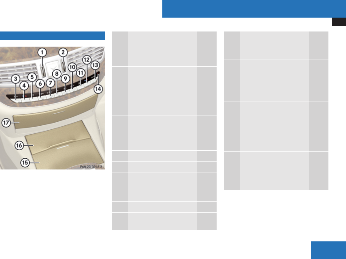
Center console
37
Center console Function Page
1Thumbwheel for air volume
control for left center air
vent 401
2Thumbwheel for air volume
control for right center air
vent 401
3Air distribution and air
volume, driver’s side
(automatic mode) 399
4Temperature control,
driver’s side 400
5Manual fan speed
adjustment, driver’s side 403
6Front defroster 403
7Air recirculation 404
8Climate control on/off 398
9Residual engine heat and
ventilation (REST) 405
aRear window defroster 406
bManual fan speed
adjustment, passenger side 403
Function Page
cTemperature control,
passenger side 400
dAir distribution and air
volume, passenger side
(automatic mode) 399
eAlarm system indicator
lamp 80
fCup holder 419
gCover of compartment
with:
Ashtray 422
Cigarette lighter 422
hCover of compartment
with:
CD/DVD changer 202
PCMCIA card slot 204
At a glance
Z
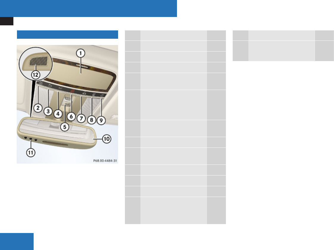
Overhead control panel
38
Overhead control panel Function Page
1Eyeglasses compartment 416
2Left reading lamp on/off 330
3Rear interior lighting on/off 330
4Front interior lighting on/
off 330
5Power tilt/sliding sunroof
switch or panorama roof
with power tilt/sliding
panel switch
406,
409
6Tele Aid (emergency call
system) button 425
7Interior lighting control 330
8Opening/closing rear roller
sunblinds 410
9Right reading lamp on/off 330
aRear view mirror 320
bGarage door opener 432
cHands-free microphone for:
Tele Aid (emergency call
system) 425
Function Page
Telephone 424
Voice Control 254
At a glance
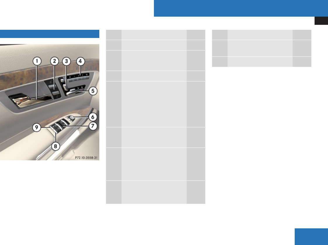
Driver’s door control panel
39
Driver’s door control panel Function Page
1Inside door handle 300
2Central unlocking switch 301
Central locking switch 301
3Seat adjustment switch 310
4Memory function (for
storing seat, exterior
mirror, and steering wheel
settings) 323
Selector button for front
passenger seat 311
5Seat heating 317
Seat ventilation 317
6Exterior rear view mirror
adjustment 320
Power-folding exterior rear
view mirrors 321
7Switches for opening/
closing front and rear door
windows 334
Function Page
8Remote trunk opening/
closing switch 302
9Override switch 67
At a glance
Z
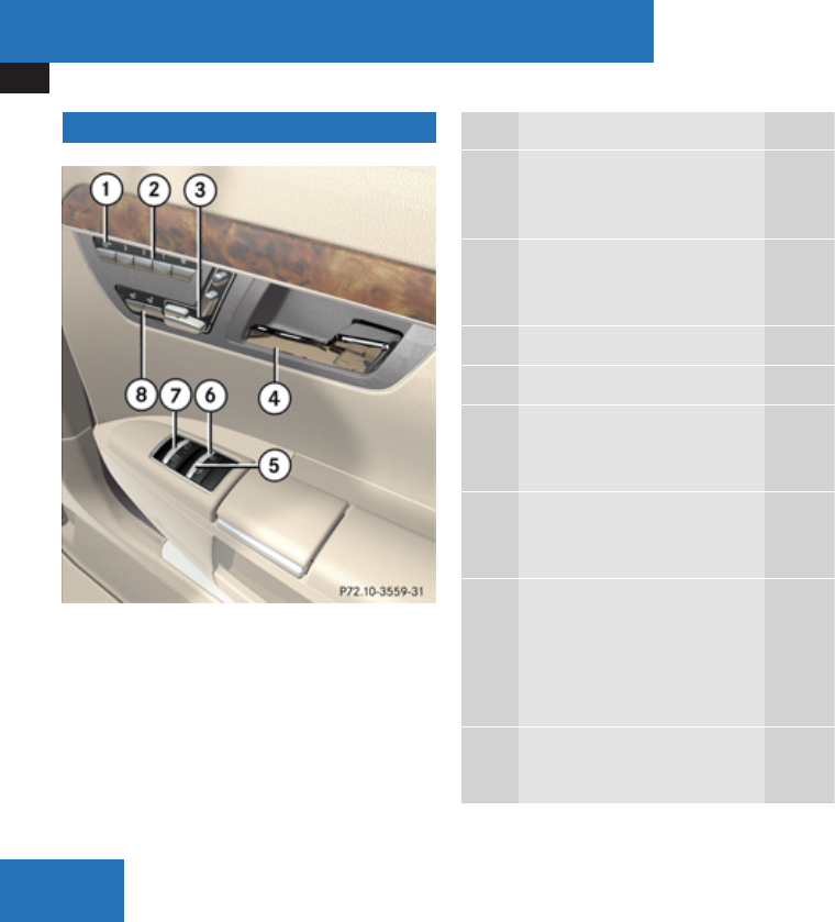
Rear door control panel
40
Rear door control panel Function Page
1Selector button for right
front passenger seat
adjustment3311
2Memory function (for
storing seat settings),
Canada only 323
3Seat adjustment switch 310
4Inside door handle
5Switch for extending/
retracting rear window
sunshade 421
6Button for extending/
retracting panorama roof
sunblind 409
7Switches for opening/
closing door windows 334
Switches for opening/
closing rear side window
sunshades 335
5Seat heating 317
Seat ventilation 317
3This switch is located on the right rear passenger side only.
At a glance


42


Occupant safety
44
Vehicle equipment
iThis Operator’s Manual describes all
features, standard or optional, potentially
available for your vehicle at the time of
purchase. Please be aware that your
vehicle might not be equipped with all
features described in this manual.
Occupant safety
Introduction
In this section you will learn the most
important facts about the restraint system
components of the vehicle.
The restraint systems are
RSeat belts
RChild restraints
RLower Anchors and Tethers for CHildren
(LATCH)
Additional protection potential is provided by:
RSupplemental Restraint System (SRS) with
-Air bags
-Air bag control unit (with crash sensors)
-Emergency Tensioning Device (ETD) for
seat belts
-Seat belt force limiter
RActive head restraints
RPreventive occupant safety (PRE-SAFE®)
RAir bag system components with
-Front passenger front air bag off
indicator lamp
-Front passenger seat with Occupant
Classification System (OCS)
Although the systems are independent, their
protective functions work in conjunction with
each other.
GWarning!
Modifications to or work improperly
conducted on restraint system
components or their wiring, as well as
tampering with interconnected electronic
systems, can lead to the restraint systems
no longer functioning as intended.
Air bags or Emergency Tensioning Devices
(ETDs), for example, could deploy
inadvertently or fail to deploy in accidents
although the deceleration threshold for air
bag deployment is exceeded. Therefore,
never modify the restraint systems. Do not
tamper with electronic components or their
software.
iFor information on infants and children
traveling with you in the vehicle and
restraint systems for infants and children,
Safety and security

Occupant safety
45
see “Children in the
vehicle” (Y page 62).
SRS indicator lamp
The SRS system conducts a self-test when
the ignition is switched on and in regular
intervals while the engine is running. This
facilitates detection of system malfunctions.
The = indicator lamp in the instrument
cluster comes on when the ignition is
switched on and goes out no later than a few
seconds after the engine has been started.
The SRS components are in operational
readiness if the = indicator lamp is not lit
when the engine is running.
A malfunction in the system has been
detected if the = indicator lamp
Rfails to go out after approximately
4 seconds after the engine is started
Rdoes not come on at all
Rcomes on after the engine was started or
while driving
GWarning!
In the event that the = indicator lamp
comes on while driving or does not come
on at all, the SRS self-check has detected
a malfunction. For your safety, we strongly
recommend that you contact an authorized
Mercedes-Benz Center immediately to
have the system checked; otherwise the
SRS may not deploy when needed in an
accident, which could result in serious or
fatal injury, or it might deploy unexpectedly
and unnecessarily which could also result
in injury.
In addition, improper work on the SRS
creates a risk of rendering the SRS
inoperative or causing unintended air bag
deployment. Work on the SRS must
therefore only be performed by qualified
technicians. Contact an authorized
Mercedes-Benz Center.
If it is necessary to modify an air bag system
to accommodate a person with disabilities,
contact an authorized Mercedes-Benz
Center or call our Customer Assistance
Center at 1-800-FOR-MERCedes
(1-800-367-6372) for details.
Air bags
GWarning!
Air bags are designed to reduce the
potential of injury and fatality in certain
frontal impacts (front air bags), side
impacts (side impact air bags and window
curtain air bags), or rollovers (window
curtain air bags). However, no system
available today can completely eliminate
injuries and fatalities.
The deployment of the air bags temporarily
releases a small amount of dust from the
air bags. This dust, however, is neither
injurious to your health, nor does it indicate
a fire in the vehicle. The dust might cause
some temporary breathing difficulty for
people with asthma or other breathing
trouble. To avoid this, you may wish to get
out of the vehicle as soon as it is safe to do
so. If you have any breathing difficulty but
cannot get out of the vehicle after the air
bag inflates, then get fresh air by opening a
window or door.
GWarning!
To reduce the risk of injury when the front
air bags inflate, it is very important for the
driver and front passenger to always be in
Safety and security
Z

Occupant safety
46
a properly seated position and to wear their
respective seat belt.
For maximum protection in the event of a
collision always be in normal seated
position with your back against the seat
backrest. Fasten your seat belt and make
sure it is properly positioned on your body.
Since the air bag inflates with considerable
speed and force, a proper seating position
and correct positioning of the hands on the
steering wheel will help to keep you at a
safe distance from the air bag. Occupants
who are not wearing their seat belt, are not
seated properly or are too close to the air
bag can be seriously injured or killed by an
air bag as it inflates with great force
instantaneously:
RSit with the seat belt properly fastened in
a position that is as upright as possible
with your back against the seat backrest.
RMove the driver seat as far back as
possible, still permitting proper
operation of vehicle controls. The
distance from the center of the driver’s
chest to the center of the air bag cover
on the steering wheel must be at least
10 inches (25 cm) or more. You should
be able to accomplish this by adjusting
the seat and steering wheel. If you have
any difficulties, please contact an
authorized Mercedes-Benz Center.
RDo not lean your head or chest close to
the steering wheel or dashboard.
RKeep hands on the outside of the steering
wheel rim. Placing hands and arms inside
the rim can increase the risk and
potential severity of hand/arm injury
when the driver front air bag inflates.
RAdjust the front passenger seat as far as
possible rearward from the dashboard
when the seat is occupied.
ROccupants, especially children, should
never place their bodies or lean their
heads in the area of the door where the
side impact air bag inflates. This could
result in serious injuries or death should
the side impact air bag be deployed.
Always sit as upright as possible, wear
the seat belt properly and use an
appropriately sized infant restraint,
toddler restraint, or booster seat
recommended for the size and weight of
the child.
Failure to follow these instructions can
result in severe injuries to you or other
occupants.
If you sell your vehicle, it is important that
you make the buyer aware of this safety
information. Be sure to give the buyer this
Operator’s Manual.
GWarning!
Accident research shows that the safest
place for children in an automobile is in the
rear seat.
There is a possibility for a side impact air
bag-related injury if occupants, especially
children, are not properly seated or
restrained when next to a side impact air
bag which needs to deploy rapidly in a side
impact in order to do its job.
To help avoid the possibility of injury,
please follow these guidelines:
(1) Occupants, especially children,
should never place their bodies
or lean their heads in the area of
the door where the side impact
air bags inflates. This could
result in serious injuries or death
Safety and security

Occupant safety
47
should the side impact air bags
be deployed.
(2) Always sit as upright as possible,
properly use the seat belts, and
for children 12 years old and
under, use an appropriately
sized infant restraint, toddler
restraint, or booster seat
recommended for the size and
weight of the child.
(3) Always wear seat belts properly.
If you believe that, even with the use of
these guidelines, it would be safer for your
rear seat occupants to have the rear
mounted side impact air bags deactivated,
then deactivation can be carried out upon
your written request at an authorized
Mercedes-Benz Center at an additional
cost.
Please contact an local authorized
Mercedes-Benz Center or call the
Customer Assistance Center (in the USA)
at 1-800-FOR-MERCedes
(1-800-367-6372), or Customer Service (in
Canada) at 1-800-387-0100 for details.
Air bags are designed to deploy only in certain
frontal impacts (front air bags), side impacts
(side impact and window curtain air bags)
which exceed preset deployment thresholds,
and in certain rollovers (window curtain air
bags). Only in the event of such a situation
will they provide their supplemental
protection.
The driver and passengers should always
wear their seat belts. Otherwise it is not
possible for the air bags to provide their
supplemental protection.
In case of other types of impacts and impacts
below air bag deployment thresholds, air
bags will not deploy. The driver and
passengers will then be protected to the
extent possible by a properly fastened seat
belt. A properly fastened seat belt is also
needed to provide the best possible
protection in a rollover.
Air bags are not a substitute for seat belts.
Always wear your seat belt, regardless of
whether or not your vehicle is equipped with
air bags.
It is important to your safety and that of your
passengers that you replace deployed air
bags and repair any malfunctioning air bags
to make sure the vehicle will continue to
provide supplemental crash protection for
occupants.
Safety guidelines for the seat belt,
Emergency Tensioning Device (ETD)
and air bag
GWarning!
RDamaged seat belts or seat belts that
have been subjected to stress in an
accident must be replaced and their
anchoring points must also be checked.
Only use seat belts installed or supplied
by an authorized Mercedes-Benz Center.
RAir bags and pyrotechnic Emergency
Tensioning Devices (ETDs) contain
perchlorate material, which may require
special handling and regard for the
environment. Check with your local
government’s disposal guidelines.
California residents, see
www.dtsc.ca.gov/HazardousWaste/
Perchlorate/index.cfm.
RAir bags and ETDs are designed to
function on a one-time-only basis. An air
bag or ETD that is deployed must be
replaced. PRE-SAFE® has electrically
operated reversible pre-tensioners in
addition to the pyrotechnic ETDs.
RDo not pass seat belts over sharp edges.
They could tear.
Safety and security
Z
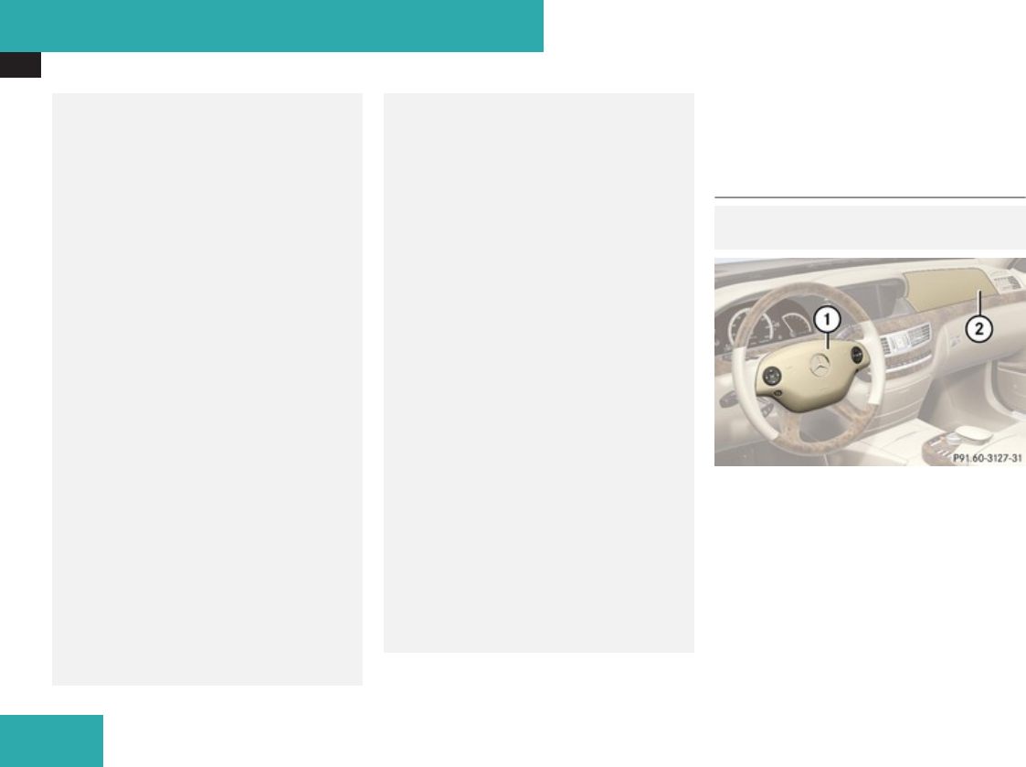
Occupant safety
48
RDo not make any modification that could
change the effectiveness of the seat
belts.
RDo not bleach or dye seat belts as this
may severely weaken them. In a crash
they may not be able to provide adequate
protection.
RNo modifications of any kind may be
made to any components or wiring of the
SRS. This includes changing or removing
any component or part of the SRS, the
installation of additional trim material,
seat covers, badges, etc. over the
steering wheel hub, front passenger front
air bag cover, outboard sides of the seat
backrests, door trim panels, or door
frame trims, and installation of additional
electrical/electronic equipment on or
near SRS components and wiring. Keep
area between air bags and occupants
free of objects (e.g. packages, purses,
umbrellas, etc.).
RDo not hang items such as coat hangers
from the coat hooks or handles over the
door. These items may be thrown around
in the vehicle and cause head and other
injuries when the window curtain air bag
is deployed.
RAir bag system components will be hot
after an air bag has inflated. Do not touch
them.
RNever place your feet on the instrument
panel, dashboard, or on the seat. Always
keep both feet on the floor in front of the
seat.
RIn addition, improper repair work on the
SRS creates a risk of rendering the SRS
inoperative or causing unintended air bag
deployment. Work on the SRS must
therefore only be performed by qualified
technicians. Contact an authorized
Mercedes-Benz Center.
RFor your protection and the protection of
others, when scrapping the air bag unit
or ETD, our safety instructions must be
followed. These instructions are available
from any authorized Mercedes-Benz
Center.
RGiven the considerable deployment
speed, required inflation volume, and the
material of the air bags, there is the
possibility of abrasions or other,
potentially more serious injuries
resulting from air bag deployment.
If you sell your vehicle, we strongly
recommend that you inform the subsequent
owner that the vehicle is equipped with SRS
and refer them to the applicable section in the
Operator’s Manual.
Front air bags
GObserve Safety notes, see
page 47.
1Driver front air bag
2Front passenger front air bag
The front air bags are designed to provide
increased protection for the driver and front
passenger against the risk of injuries to the
head and thorax.
Safety and security
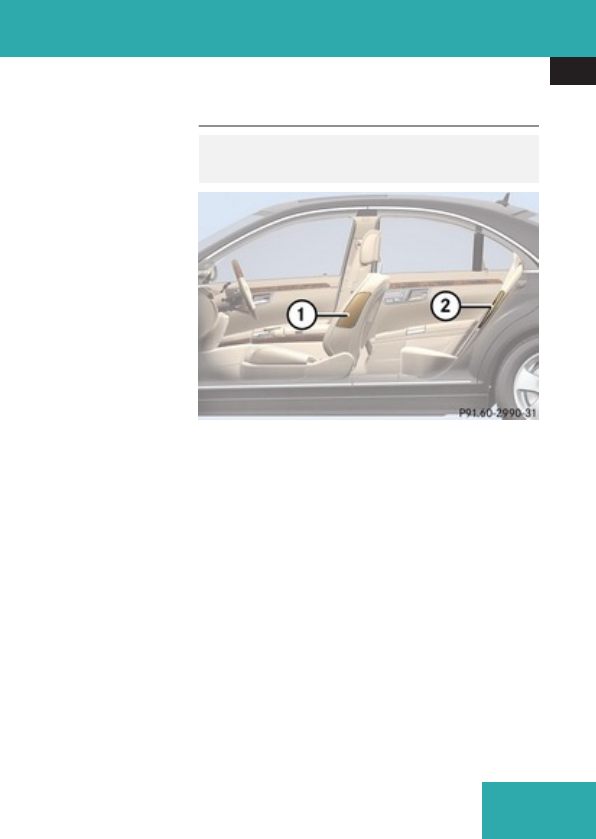
Occupant safety
49
Driver and front passenger front air bags are
deployed
Rin the event of certain frontal impacts
Rif impact exceeds a preset deployment
threshold
Rif the system determines that air bag
deployment can offer additional protection
to that provided by the seat belt
Rdepending on whether the seat belt is in
use
Rindependently of the side impact air bags
and/or the window curtain air bags
The front air bags in this vehicle have been
designed to inflate in two stages. This allows
the air bags to have different rates of inflation
that are based on the vehicle deceleration
rate as assessed by the air bag control unit.
On the front passenger side, front air bag
2 deployment is additionally influenced by
the passenger’s weight category as identified
by the Occupant Classification System (OCS)
(Y page 50).
The lighter the front passenger side
occupant, the higher the vehicle deceleration
rate required for second stage inflation of
front air bag 2.
The air bags will not deploy in impacts which
do not exceed the system’s preset
deployment thresholds. You will then be
protected by the fastened seat belts.
The front air bags will not deploy in the event
of a rollover unless the vehicle’s rate of
longitudinal deceleration or acceleration
exceeds the preset deployment threshold for
the front air bags.
The front passenger front air bag 2 will only
be deployed if
Rthe system, based on OCS weight sensor
readings, detects that the front passenger
seat is occupied
Rthe 59 indicator lamp in the
center console is not lit (Y page 53)
Rthe impact exceeds a preset deployment
threshold
Side impact air bags
GObserve Safety notes, see
page 47.
1Front side impact air bag
2Rear side impact air bag
When deployed, the side impact air bags are
designed to provide increased protection for
the thorax (but not the head, neck and arms)
of the occupants on the side of the vehicle on
which the impact occurs.
The side impact air bags are deployed
Ron the impacted side of the vehicle
Rin side impacts exceeding a preset
deployment threshold
Rregardless of whether the seat belt is in use
Safety and security
Z
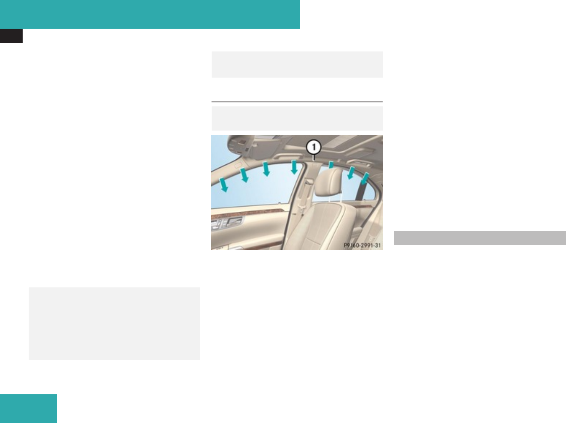
Occupant safety
50
Rindependently of the front air bags
Rindependently of the ETDs
The front passenger side impact air bag will
not deploy if the OCS senses that the front
passenger seat is empty and the front
passenger seat belt is not fastened (latch
plate is not inserted into the buckle). With an
empty front passenger seat and the seat belt
fastened (latch plate properly inserted into
buckle) the front passenger side impact air
bag will deploy independently of the empty
seat.
The side impact air bags are not deployed in
side impacts which do not exceed the
system’s deployment threshold.
The side air bags will not deploy in the event
of a rollover unless the vehicle’s rate of lateral
deceleration or acceleration exceeds the
preset deployment threshold for the side air
bags.
GWarning!
Only use seat covers which have been
tested and approved by Mercedes-Benz for
your vehicle model. Using other seat covers
may interfere with or prevent the
deployment of the side impact air bags.
Contact an authorized Mercedes-Benz
Center for availability.
Window curtain air bags
GObserve Safety notes, see
page 47.
1Window curtain air bag
When deployed, window curtain air bags 1
are designed to provide increased protection
for the head (but not the chest or arms) of the
occupants on the side of the vehicle on which
the impact occurs.
Window curtain air bags 1 are deployed
Ron the impacted side of the vehicle
Rin side impacts exceeding a preset
deployment threshold
Rindependently of the front air bags
Rregardless of whether the front passenger
seat is occupied
Rregardless of whether the seat belt is in use
Rin certain vehicle rollovers, if the system
determines that air bag deployment can
offer additional protection to that provided
by the seat belt
Window curtain air bags 1 are not deployed
in impacts which do not exceed the system’s
deployment threshold.
Window curtain air bags 1 deploy in the area
indicated by the arrows.
Occupant Classification System
The Occupant Classification System (OCS)
automatically turns the front passenger front
air bag on or off based on the classified
occupant weight category determined by
weight sensor readings from the front
passenger seat.
The system does not deactivate the front
passenger side impact air bag, the window
curtain air bag and the Emergency Tensioning
Devices (ETDs).
Occupants must sit with the seat belt
properly fastened in a position that is as
Safety and security

Occupant safety
51
upright as possible with their back against the
seat backrest and feet on the floor to be
correctly classified. If the occupant’s weight
is transferred to another object in the vehicle
(e.g. by leaning on armrests), the OCS may
not be able to properly approximate the
occupant’s weight category.
Furthermore, the occupant weight may
appear to increase or decrease due to the
following: objects hanging on the seat, lodged
underneath the seat, stuffed between the
seat and middle console or the seat and door,
other passengers pushing on the seat, or
objects applying pressure to the back of the
seat. Always make sure the seat has
clearance in all directions at all times.
iIf your seat, including the trim cover and
cushion, needs to be serviced in any way,
take the vehicle to an authorized
Mercedes-Benz Center.
Only seat accessories approved by
Mercedes-Benz may be used.
Both the driver and the front passenger
should always use the 59
indicator lamp as an indication of whether or
not the front passenger is properly
positioned.
GWarning!
If the 59 indicator lamp
illuminates when an adult or someone
larger than a small individual is in the front
passenger seat, have the front passenger
re-position himself or herself in the seat
until the 59 indicator lamp
goes out, or check whether objects are
caught under or around the seat.
In the event of a collision, the air bag control
unit will not allow front passenger front air
bag deployment when the OCS has
classified the front passenger seat
occupant as weighting as much as or less
than a typical 12-month-old child in a
standard child restraint or if the front
passenger seat is classified as being empty.
When the OCS senses that the front
passenger seat occupant is classified as
being up to or less than the weight of a
typical 12-month-old child in a standard
child restraint, the 59
indicator lamp will illuminate when the
engine is started and remain illuminated,
indicating that the front passenger front air
bag is deactivated.
When the OCS senses that the front
passenger seat is classified as being empty,
the 59 indicator lamp will
illuminate when the engine is started and
remain illuminated, indicating that the front
passenger front air bag is deactivated.
When the OCS senses that the front
passenger seat occupant is classified as
being heavier than the weight of a typical
12-month-old child seated in a standard
child restraint or as being a small individual
(such as a young teenager or a small adult),
the 59 indicator lamp will
illuminate for approximately 6 seconds
when the engine is started and then,
depending on occupant weight sensor
readings from the seat, remain illuminated
or go out. With the 59
indicator lamp illuminated, the front
passenger front air bag is deactivated. With
the 59 indicator lamp out, the
front passenger front air bag is activated.
When the OCS senses that the front
passenger seat occupant is classified as an
adult or someone larger than a small
individual, the 59 indicator
lamp will illuminate for approximately 6
seconds when the engine is started and
then go out, indicating that the front
passenger front air bag is activated.
Safety and security
Z

Occupant safety
52
If the 59 indicator lamp is
illuminated, the front passenger front air
bag is deactivated and will not be deployed.
If the 59 indicator lamp is not
illuminated, the front passenger front air
bag is activated and will be deployed
Rin the event of certain frontal impacts
Rif impact exceeds a preset deployment
threshold
Rindependently of the side impact air bags
If the front passenger front air bag is
deployed, the rate of inflation will be
influenced by
Rthe rate of relevant vehicle deceleration
as assessed by the air bag control unit
Rthe front passenger’s weight category as
identified by the OCS
For more information on air bag display
messages, see (Y page 498).
GWarning!
According to accident statistics, children
are safer when properly restrained in the
rear seating positions than in the front
seating position. Thus, we strongly
recommend that children be placed in the
rear seats whenever possible. Regardless
of seating position, children 12 years old
and under must be seated and properly
secured in an appropriate infant restraint,
toddler restraint, or booster seat
recommended for the size and weight of the
child.
The infant or child restraint must be
properly secured with the vehicle’s seat
belt, the seat belt and top tether strap, or
lower anchors and top tether strap, fully in
accordance with the child seat
manufacturer’s instructions.
Occupants, especially children, should
always sit as upright as possible, wear the
seat belt properly and use an appropriately
sized infant restraint, toddler restraint, or
booster seat recommended for the size and
weight of the child.
Children can be killed or seriously injured
by an inflating air bag. Note the following
important information when circumstances
require you to place a child in the front
passenger seat:
RYour vehicle is equipped with air bag
technology designed to deactivate the
front passenger front air bag in your
vehicle when the system senses the
weight of a typical 12-month-old child or
less along with the weight of a standard
appropriate child restraint on the front
passenger seat.
RA child in a rear-facing child restraint on
the front passenger seat will be seriously
injured or even killed if the front
passenger front air bag inflates in a
collision which could occur under some
circumstances, even with the air bag
technology installed in your vehicle. The
only means to completely eliminate this
risk is to never place a child in a rear-
facing child restraint in the front seat. We
therefore strongly recommend that you
always place a child in a rear-facing child
restraint in a backseat.
RIf you must install a rear-facing child
restraint on the front passenger seat
because circumstances require you to do
so, make sure the 59
indicator lamp is illuminated, indicating
that the front passenger front air bag is
deactivated. Should the 59
indicator lamp not illuminate or go out
while the restraint is installed, please
check installation. Periodically check the
59 indicator lamp while
Safety and security
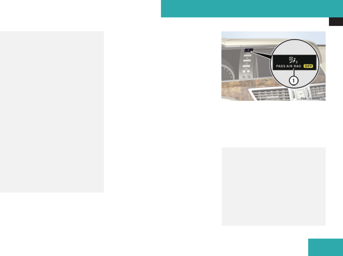
Occupant safety
53
driving to make sure the
59 indicator lamp is
illuminated. If the 59
indicator lamp goes out or remains out,
do not transport a child on the front
passenger seat until the system has been
repaired.
A child in a rear-facing child restraint on
the front passenger seat will be seriously
injured or even killed if the front
passenger front air bag inflates.
RIf you have to place a child in a forward-
facing child restraint on the front
passenger seat, move the seat as far
back as possible, use the proper child
restraint recommended for the age, size
and weight of the child, and secure child
restraint with the vehicle’s seat belt
according to the child seat
manufacturer’s instructions. For children
larger than the typical 12-month-old
child, the front passenger front air bag
may or may not be activated.
Deployment of the driver front air bag does
not mean that the front passenger front air
bag also should have deployed.
The OCS may have determined:
Rthat the seat was empty or occupied by the
weight up to or less than that of a typical
12-month-old child seated in a standard
child restraint – both instances where the
system suppresses deployment of the front
passenger front air bag even though the
impact met the criteria and was of
sufficient severity to deploy the driver front
air bag
Rthat the seat was occupied by a small
individual (such as a young teenager or a
small adult) or a child who weighs more
than the weight of a typical 12-month-old
child in a standard child restraint – both of
which are instances where the system may
suppress deployment of the front
passenger front air bag even though the
impact met the criteria and was of
sufficient severity to deploy the driver front
air bag
1Front passenger front air bag off indicator
lamp
The 59 indicator lamp 1 will be
illuminated, except with the SmartKey
removed from the starter switch or with the
starter switch in position 0.
GWarning!
If the = indicator lamp and the
59 indicator lamp are lit at the
same time, there is a malfunction in the
OCS. The front passenger front air bag will
be deactivated in this case. Have the
system checked as soon as possible by
qualified technicians. Contact an
authorized Mercedes-Benz Center.
Only have the seat repaired or replaced at
an authorized Mercedes-Benz Center.
Safety and security
Z

Occupant safety
54
In order to ensure proper operation of the
air bag system and OCS:
RDo not place more than 4.4 lb (2 kg) into
the storage bag on the back of the front
passenger seat. Otherwise, the OCS may
not be able to properly approximate the
occupant weight category.
RDo not place objects under and/or
around the front passenger seat.
RDo not hang anything from or attach any
items to the seats.
RDo not stuff objects such as books
between the front passenger seat and
the center console or front passenger
door.
RDo not move the front passenger seat
backwards against stiff objects.
RSit with the seat belt properly fastened in
a position that is as upright as possible
with your back against the seat backrest.
RWhile seated, an occupant should not
position him/herself in such a way as to
cause the occupant’s weight to be lifted
from the seat bottom as this may result
in the OCS being unable to correctly
approximate the occupant’s weight
category.
RRead and observe all warnings in this
chapter.
Occupant Classification System Self-
test
After turning the SmartKey in the starter
switch to position 1 or 2 or pressing the
KEYLESS-GO start/stop button once or
twice, the 59 indicator lamp
illuminates. If an adult occupant is properly
sitting on the front passenger seat and the
system classifies the occupant as an adult,
the 59 indicator lamp will
illuminate and go out after approximately 6
seconds.
If the seat is not occupied and the system
classifies the front passenger seat as being
empty, the 59 indicator lamp
will illuminate and not go out.
GWarning!
If the 59 indicator lamp does
not illuminate, the system is not
functioning. You must contact an
authorized Mercedes-Benz Center before
seating any child on the front passenger
seat.
For more information, see the “Practical
hints” section (Y page 559).
GWarning!
Never place anything between seat cushion
and child seat (e.g. pillow), since it reduces
the effectiveness of the OCS. The bottom
and back of the child seat must make full
contact with the passenger seat cushion
and backrest.
If necessary, adjust the tilt of the passenger
seat backrest.
An incorrectly mounted child seat could
cause injuries to the child in case of an
accident, instead of increasing protection
for the child.
Follow the manufacturer’s instructions for
installation of child seats.
Safety and security

Occupant safety
55
Seat belts
Safety notes
The use of seat belts and infant and child
restraint systems is required by law in all 50
states, the District of Columbia, the U.S.
territories and all Canadian provinces.
Even where this is not the case, all vehicle
occupants should have their seat belts
fastened whenever the vehicle is in motion.
For information on infants and children
traveling with you in the vehicle and restraint
systems for infants and children, see
“Children in the vehicle” (Y page 62).
GWarning!
Always fasten your seat belt before driving
off. Always make sure all of your
passengers are properly restrained. You
and your passengers should always wear
seat belts.
Failure to wear and properly fasten and
position your seat belt greatly increases
your risk of injuries and their likely severity
in an accident.
If you are ever in an accident, your injuries
can be considerably more severe without
your seat belt properly buckled. Without
your seat belt buckled, you are much more
likely to hit the interior of the vehicle or be
ejected from it. You can be seriously injured
or killed.
In the same crash, the possibility of injury
or death is lessened if you are properly
wearing your seat belt. The air bags can
only protect as intended if the occupants
are properly wearing their seat belts.
GWarning!
Never ride in a moving vehicle with the seat
backrest in an excessively reclined position
as this can be dangerous. You could slide
under the seat belt in a collision. If you slide
under it, the seat belt would apply force at
the abdomen or neck. That could cause
serious or even fatal injuries. The seat
backrest and seat belt provide the best
restraint when the wearer is in a position
that is as upright as possible and the seat
belt is properly positioned on the body.
GWarning!
Never let more people ride in the vehicle
than there are seat belts available. Make
sure everyone riding in the vehicle is
correctly restrained with a separate seat
belt. Never use a seat belt for more than
one person at a time.
GWarning!
Damaged seat belts or seat belts that have
been subjected to stress in an accident
must be replaced and their anchoring
points must also be checked.
Only use seat belts which have been
approved by Mercedes-Benz.
Do not make any modifications to the seat
belts. This can lead to unintended
activation of the ETDs or to their failure to
activate when necessary.
Do not bleach or dye seat belts as this may
severely weaken them. In a crash they may
not be able to provide adequate protection.
Have all work carried out only by qualified
technicians. Contact an authorized
Mercedes-Benz Center.
Proper use of seat belts
GWarning!
USE SEAT BELTS PROPERLY
RSeat belts can only work when used
properly. Never wear seat belts in any
other way than as described in this
Safety and security
Z

Occupant safety
56
section, as that could result in serious
injuries in case of an accident.
REach occupant should wear their seat
belt at all times, because seat belts help
reduce the likelihood of and potential
severity of injuries in accidents, including
rollovers. The integrated restraint system
includes SRS (driver front air bag, front
passenger front air bag, side impact air
bags, window curtain air bags for side
windows), Emergency Tensioning
Devices (ETDs), seat belt force limiters,
and front seat knee bolsters.
The system is designed to enhance the
protection offered to properly belted
occupants in certain frontal (front air
bags and ETDs) and side (side impact air
bags, window curtain air bags, and ETDs)
impacts which exceed preset
deployment thresholds and in certain
rollovers (window curtain air bags and
ETDs).
RNever wear the shoulder belt under your
arm, against your neck or off your
shoulder. In a frontal crash, your body
would move too far forward. That would
increase the chance of head and neck
injuries. The seat belt would also apply
too much force to the ribs or abdomen,
which could severely injure internal
organs such as your liver or spleen.
Adjust the seat belt so that the shoulder
section is located as close as possible to
the middle of the shoulder (it should not
touch the neck). Never pass the shoulder
portion of the seat belt under your arm.
For this purpose, you can adjust the
height of the seat belt outlet (depending
on vehicle production date).
RPosition the lap belt as low as possible
on your hips and not across the
abdomen. If the lap belt is positioned
across your abdomen, it could cause
serious injuries in a crash.
RNever wear seat belts over rigid or
breakable objects in or on your clothing,
such as eyeglasses, pens, keys etc., as
these might cause injuries.
RMake sure the seat belt is always fitted
snugly. Take special care of this when
wearing loose clothing.
RNever use a seat belt for more than one
person at a time. Do not fasten a seat belt
around a person and another person or
other objects at the same time.
RSeat belts should not be worn twisted. In
a crash, you would not have the full width
of the seat belt to distribute impact
forces. The twisted seat belt against your
body could cause injuries.
RPregnant women should also always use
a lap/shoulder belt. The lap belt portion
should be positioned as low as possible
on the hips to avoid any possible
pressure on the abdomen.
RPlace the seat backrest in a position that
is as upright as possible.
RCheck your seat belt during travel to
make sure it is properly positioned.
RNever place your feet on the instrument
panel, dashboard, or on the seat. Always
keep both feet on the floor in front of the
seat.
RWhen using a seat belt to secure infant
restraints, toddler restraints, or children
in booster seats, always follow the child
seat manufacturer’s instructions.
GWarning!
Do not pass seat belts over sharp edges.
They could tear.
Safety and security
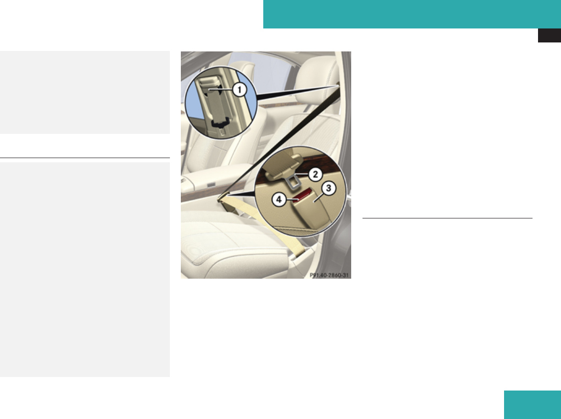
Occupant safety
57
Do not allow the seat belt to get caught in
the door or in the seat adjustment
mechanism. This could damage the seat
belt.
Never attempt to make modifications to
seat belts. This could impair the
effectiveness of the seat belts.
Fastening the seat belts
GWarning!
According to accident statistics, children
are safer when properly restrained in the
rear seating positions than in the front
seating position. Thus, we strongly
recommend that children be placed in the
rear seats whenever possible. Regardless
of seating position, children 12 years old
and under must be seated and properly
secured in an appropriately sized infant
restraint, toddler restraint, or booster seat
recommended for the size and weight of the
child. For additional information, see
“Children in the vehicle”.
A child’s risk of serious or fatal injuries is
significantly increased if the child restraints
are not properly secured in the vehicle
and/or the child is not properly secured in
the child restraint.
1Seat belt outlet
2Latch plate
3Buckle
4Seat belt release button
XWith a smooth motion, pull the seat belt out
of seat belt outlet 1.
XPlace the shoulder portion of the seat belt
across the top of your shoulder and the lap
portion across your hips.
XPush latch plate 2 into buckle 3 until it
clicks.
XIf necessary, adjust the seat belt to the
correct height (depending on vehicle
production date).
XIf necessary, tighten the lap portion to a
snug fit by pulling shoulder portion up.
Seat belt outlet height adjustment
Depending on vehicle production date, your
vehicle adjust the seat belt height for the
driver and front passenger seat
automatically, or you can adjust the height of
the seat belt for the driver and front
passenger seat manually. The seat belts for
the rear outer seats are adjusted
automatically.
Safety and security
Z
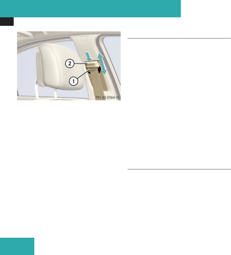
Occupant safety
58
1Seat belt height adjuster
2Release button
XRaising: Slide seat belt height adjuster
1 upward.
Seat belt height adjuster 1 engages in
different positions.
XLowering: Press and hold release button
2.
XSlide seat belt height adjuster 1
downward.
XRelease button 2 and make sure seat belt
height adjuster 1 engages into place.
Releasing the seat belts
XPress seat belt release button 4
(Y page 57).
Allow the retractor to completely rewind
the seat belt by guiding latch plate 2
(Y page 57).
! Make sure the seat belt retracts fully so
that the seat belt and/or latch plate cannot
get caught or pinched in the door or in the
seat mechanism. This can damage the seat
belt and impair its effectiveness, and/or
cause damage to the door and/or door trim
panel. Such damage is not covered by the
Mercedes-Benz Limited Warranty.
Damaged seat belts must be replaced.
Contact an authorized Mercedes-Benz
Center.
Enhanced seat belt reminder system
When the engine is started, the seat belt
telltale < will always illuminate for
6 seconds to remind you and your passengers
to fasten your seat belts.
If the driver’s seat belt is not fastened when
the engine is started, an additional warning
chime will also sound for a maximum of
6 seconds or until the driver’s seat belt is
fastened.
If after these 6 seconds the driver’s or the
front passenger’s seat belt (with the front
passenger seat occupied) is not fastened with
front doors closed,
Rthe seat belt telltale < remains
illuminated for as long as either the driver’s
or front passenger’s seat belt is not
fastened.
Rand if the vehicle speed once exceeds
15 mph (25 km/h), the seat belt telltale
< starts flashing and a warning chime
sounds with increasing intensity for a
maximum of 60 seconds or until the
driver’s and front passenger’s seat belt are
fastened.
If you and/or your passenger release the
seat belt during driving, the seat belt
telltale < starts flashing and the
warning chime sounds as described before.
If the driver’s or the front passenger’s seat
belt remains unfastened after 60 seconds,
the warning chime stops sounding, the seat
belt telltale < stops flashing but
continues to be illuminated.
After a vehicle standstill, the warning chime
is reactivated and the seat belt telltale
< is flashing again if the vehicle speed
once exceeds 15 mph (25 km/h).
Safety and security

Occupant safety
59
The seat belt telltale < will only go out if
both the driver’s and the front passenger’s
seat belt (with the front passenger seat
occupied) are fastened, or the vehicle is
standing still and a front door is opened.
For more information, see “Practical
hints” (Y page 552).
Emergency Tensioning Device (ETD),
seat belt force limiter
The seat belts for the front seats and rear
outer seats are equipped with ETDs and seat
belt force limiters.
The ETDs are designed to activate in the
following cases:
Rin frontal or rear-end impacts exceeding
the system’s preset deployment threshold
Rin side impacts exceeding the system’s
preset deployment threshold on the far
side of the impact
Rin certain vehicle rollovers
Rif the restraint systems are operational and
functioning correctly, see = indicator
lamp (Y page 45)
The ETDs for the front seats will only activate
if the front seat belts are fastened (latch plate
properly inserted into buckle).
The ETDs for the rear outer seats will activate
with or without the respective seat belts
fastened.
In an impact, the ETDs remove slack from the
seat belts in such a way that the seat belts fit
more snugly against the body. Seat belt force
limiters, when activated, are employed to
help reduce the peak force exerted by the
seat belts on occupants during a crash.
iThe ETDs do not correct an incorrect seat
position or incorrectly worn seat belts.
The ETDs do not pull occupants back
toward the seat backrest.
GWarning!
Pyrotechnic ETDs that were activated must
be replaced.
For your safety, when disposing of the
pyrotechnic ETDs always follow our safety
instructions. These are available at any
authorized Mercedes-Benz Center.
PRE-SAFE® has electrically operated
reversible pre-tensioners that do not
require replacement after activation.
Automatic comfort-fit feature seat belt
An automatic comfort-fit feature for the front
seats and for the rear outer seats (only for
vehicles with rear power seats) reduces the
retracting force of the seat belts when they
are in normal use.
Preventive occupant safety (PRE-
SAFE®)
GWarning!
PRE-SAFE® is intended to reduce the
effects of an accident on vehicle occupants
who are wearing their seat belt properly.
Despite having the PRE-SAFE® system in
your vehicle, the possibility of injuries
occurring as a result of an accident cannot
be eliminated. Therefore, you should
always drive carefully and adjust your
driving to the prevailing road, weather, and
traffic conditions.
Your vehicle takes preventive measures to
better protect the occupants in the following
hazardous situations automatically.
PRE-SAFE® takes preventive measures in
Remergency braking situations, e.g. if the
Brake Assist System (BAS) (Y page 70) is
activated
or when
Safety and security
Z

Occupant safety
60
BAS Plus (Y page 70) or the PRE-SAFE
Brake (Y page 76) is strongly intervening
Rcritical dynamic driving situations, e.g.
when the vehicle is understeering or
oversteering because it has exceeded its
physical limitations or in case of evasive
steering maneuvers at speeds above
approximately 85 mph (140 km/h)
When you are driving faster than 20 mph
(30 km/h), PRE-SAFE® takes the following
measures in such situations:
RThe front seat belts are pre-tensioned
automatically.
RIf the passenger seat is in an unfavorable
position, it will be adjusted to a better
position.
RIf the vehicle is equipped with power
adjustable rear seats and the passenger
outer seats are in an unfavorable position,
they will be adjusted to a better position.
RThe system increases the air pressure in
the air pockets (on the sides of the seat
cushion and backrest) of the multicontour
and/or drive-dynamic front seats.
RIf the vehicle is equipped with multicontour
rear seats, the system increases the air
pressure in the air pockets (on the sides of
the seat backrest) of the multicontour rear
outer seats.
RIf the vehicle is in a critical dynamic driving
situation, the door windows and the tilt/
sliding sunroof or panorama roof also
closes until only a small gap remains.
If the closing procedure of the door windows,
tilt/sliding sunroof, or panorama roof, is
blocked, the door windows, tilt/sliding
sunroof, or panorama roof, will stop and open
slightly.
Once the hazardous situation is over without
an accident occurring, PRE-SAFE® loosens
the seat belt pre-tension and decreases the
air pressure in the air pockets of the
multicontour and/or drive-dynamic seats.
You can readjust all of the settings made by
PRE-SAFE®.
If the seat belts do not release:
XAdjust the seat backrest to the rear until
the seat belt tension is diminished.
The locking mechanism releases.
! When adjusting the seat backrests, make
sure there are no items behind the seats.
Otherwise, you could damage the seats.
Active head restraints
The active head restraints are intended to
offer the driver and front passenger increased
protection from whiplash-type injuries. In the
event of a rear-end collision, the active head
restraints on the driver’s and front
passenger’s seat are designed to move
forward in the direction of travel, providing
the head with increased support earlier on in
the collision sequence. The active head
restraints move forward whether the seat is
occupied or not.
GWarning!
Do not attach any objects (e.g. hangers) to
the head restraint posts. Otherwise, the
active head restraints may not be able to
function properly or offer the intended
degree of protection they were designed for
in the event of a rear-end collision.
If the active head restraints have been
triggered in an accident, the active head
restraints must be reset. Otherwise, the
active head restraints cannot offer any
additional protection in the event of another
rear-end collision.
For information on resetting the activated
active head restraints, see “Resetting
activated head restraints” (Y page 562).
Safety and security
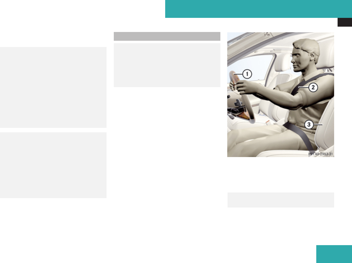
Occupant safety
61
You cannot remove the active head restraint
on the driver’s and front passenger’s seats.
GWarning!
Only use seat or head restraint covers
which have been tested and approved by
Mercedes-Benz for your vehicle model.
Using other seat or head restraint covers
may interfere with or prevent the activation
of the active head restraints and/or the
deployment of the front side impact air
bags.
Contact an authorized Mercedes-Benz
Center for availability.
GWarning!
For your protection, drive only with properly
positioned head restraints.
Adjust the head restraint so that it is as
close to the head as possible and the center
of the head restraint supports the back of
the head at eye level. This will reduce the
potential for injury to the head and neck in
the event of an accident or similar situation.
For information on head restraint adjustment,
see “Head restraints” (Y page 313).
Correct driver seat adjustment
GWarning!
In order to avoid possible loss of vehicle
control, all seat, head restraint, steering
wheel, and rear view mirror adjustments, as
well as fastening of seat belts, must be
done before the vehicle is put into motion.
1Steering wheel
2Seat belt
3Seat
Steering wheel
GObserve Safety notes, see
page 319.
XPosition steering wheel 1 properly
(Y page 319).
Safety and security
Z

Occupant safety
62
Make sure:
RYou can reach steering wheel 1 with your
arms slightly bent at the elbows.
RYou can move your legs freely.
RAll displays (including malfunction and
indicator lamps) on the instrument cluster
are clearly visible.
Seat belt
GObserve Safety notes, see
page 55.
XFasten and position your seat belt 2
(Y page 57) correctly.
Make sure:
RSeat belt 2 is always fitted snugly.
RAdjust seat belt 2 so that the shoulder
section is located as close as possible to
the middle of the shoulder.
RPlace the lap portion of seat belt 2 as low
as possible on your hips.
Seat and head restraint
GObserve Safety notes, see
page 309.
XPosition seat 3 (Y page 310) and head
restraint properly (Y page 313).
Observe the following points:
RAlways be in a properly seated position.
RThe position should be as far rearward from
the front air bag in steering wheel 1 as
possible, while still permitting proper
operation of vehicle controls.
RAdjust seat 3 to a comfortable seating
position that still allows you to reach the
accelerator/brake pedal safely.
RSeat 3 must be adjusted so that you can
correctly fasten and position your
seat belt 2.
RThe seat backrest must be in a position that
is as nearly upright as possible.
RAdjust the seat cushion so that the front
edge of the seat cushion lightly supports
your legs.
RAdjust the head restraint so that it is as
close to the head as possible and the
center of the head restraint supports the
back of the head at eye level.
RNever place hands under seat 3 or near
any moving parts while seat 3 is being
adjusted.
Children in the vehicle
Safety notes
If an infant or child is traveling with you in the
vehicle:
XSecure the child using an infant or child
restraint appropriate to the age and size of
the child.
XMake sure the infant or child is properly
secured at all times while the vehicle is in
motion.
Safety and security

Occupant safety
63
GWarning!
When leaving the vehicle, always remove
the SmartKey from the starter switch.
Always take the SmartKey with you and
lock the vehicle. Do not leave children
unattended in the vehicle, even if they are
secured in a child restraint system, or with
access to an unlocked vehicle. A child’s
unsupervised access to a vehicle could
result in an accident and/or serious
personal injury. The children could
Rinjure themselves on parts of the vehicle
Rbe seriously or fatally injured through
excessive exposure to extreme heat or
cold
Rinjure themselves or cause an accident
with vehicle equipment that can be
operated even if the SmartKey is
removed from the starter switch or
removed from the vehicle, such as seat
adjustment, steering wheel adjustment,
or the memory function.
If children open a door, they could injure
other persons or get out of the vehicle and
injure themselves or be injured by following
traffic.
Do not expose the child restraint system to
direct sunlight. The child restraint system’s
metal parts, for example, could become
very hot, and the child could be burned on
these parts.
GWarning!
Do not carry heavy or hard objects in the
passenger compartment unless they are
firmly secured in place.
Unsecured or improperly positioned cargo
increases a child’s risk of injury in the event
of
Rstrong braking maneuvers
Rsudden changes of direction
Ran accident
For more information on loading, please refer
to the “Loading and storing” (Y page 414)
chapter.
Infant and child restraint systems
GObserve Safety notes, see
page 62.
We recommend all infants and children be
properly restrained at all times while the
vehicle is in motion.
All lap/shoulder belts except the driver’s seat
belt have special seat belt retractors for
secure fastening of child restraints.
To fasten a child restraint, follow child
restraint instructions for mounting. Then pull
the shoulder belt out completely and let it
retract. During seat belt retraction, a
ratcheting sound can be heard to indicate
that the special seat belt retractor is
activated. The seat belt is now locked. Push
down on child restraint to take up any slack.
To deactivate, release the seat belt buckle
and let the seat belt retract completely. To
deactivate the special seat belt retractor for
the front passenger seat, the front passenger
seat must be in the most backward position.
The seat belt can again be used in the usual
manner.
GWarning!
Never release the seat belt buckle while the
vehicle is in motion, since the special seat
belt retractor will be deactivated.
iInformation on child seats with mounting
fittings for tether anchorages
(Y page 65).
For information on LATCH-type child seat
anchors (Y page 66).
Safety and security
Z

Occupant safety
64
The use of infant or child restraints is required
by law in all 50 states, the District of
Columbia, the U.S. territories and all
Canadian provinces.
Infants and small children should be seated
in an appropriate infant or child restraint
system, properly secured in accordance with
the manufacturer’s instructions for the child
restraint, that complies with U.S. Federal
Motor Vehicle Safety Standards 213 and 225
and Canadian Motor Vehicle Safety
Standards 213 and 210.2.
A statement by the child restraint
manufacturer of compliance with these
standards can be found on the instruction
label on the restraint and in the instruction
manual provided with the restraint.
When using any infant restraint, toddler
restraint, or booster seat, make sure to
carefully read and follow all manufacturer’s
instructions for installation and use.
Please read and observe warning labels
affixed to the inside of the vehicle and to
infant or child restraints.
GWarning!
According to accident statistics, children
are safer when properly restrained in the
rear seating positions than in the front
seating position. Thus, we strongly
recommend that children be placed in the
rear seats whenever possible. Regardless
of seating position, children 12 years old
and under must be seated and properly
secured in an appropriate infant restraint,
toddler restraint, or booster seat
recommended for the size and weight of the
child.
The infant or child restraint must be
properly secured with the vehicle’s seat
belt, the seat belt and top tether strap, or
lower anchors and top tether strap, fully in
accordance with the child seat
manufacturer’s instructions.
Occupants, especially children, should
always sit as upright as possible, wear the
seat belt properly and use an appropriately
sized infant restraint, toddler restraint, or
booster seat recommended for the size and
weight of the child.
Children can be killed or seriously injured
by an inflating air bag. Note the following
important information when circumstances
require you to place a child in the front
passenger seat:
RYour vehicle is equipped with air bag
technology designed to deactivate the
front passenger front air bag in your
vehicle when the system senses the
weight of a typical 12-month-old child or
less along with the weight of a standard
appropriate child restraint on the front
passenger seat.
RA child in a rear-facing child restraint on
the front passenger seat will be seriously
injured or even killed if the front
passenger front air bag inflates in a
collision which could occur under some
circumstances, even with the air bag
technology installed in your vehicle. The
only means to completely eliminate this
risk is to never place a child in a rear-
facing child restraint in the front seat. We
therefore strongly recommend that you
always place a child in a rear-facing child
restraint in a backseat.
RIf you must install a rear-facing child
restraint on the front passenger seat
because circumstances require you to do
so, make sure the 59
indicator lamp is illuminated, indicating
that the front passenger front air bag is
deactivated. Should the 59
indicator lamp not illuminate or go out
while the restraint is installed, please
Safety and security
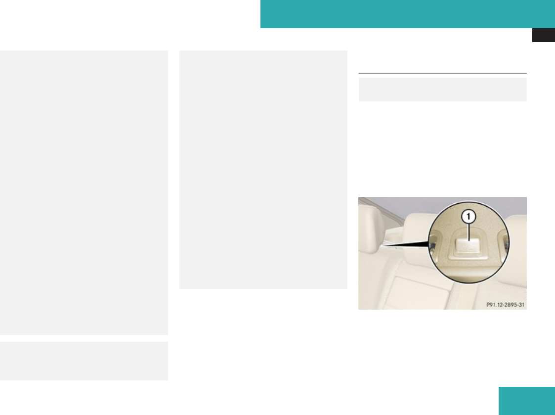
Occupant safety
65
check installation. Periodically check the
59 indicator lamp while
driving to make sure the
59 indicator lamp is
illuminated. If the 59
indicator lamp goes out or remains out,
do not transport a child on the front
passenger seat until the system has been
repaired.
A child in a rear-facing child restraint on
the front passenger seat will be seriously
injured or even killed if the front
passenger front air bag inflates.
RIf you have to place a child in a forward-
facing child restraint on the front
passenger seat, move the seat as far
back as possible, use the proper child
restraint recommended for the age, size
and weight of the child, and secure child
restraint with the vehicle’s seat belt
according to the child seat
manufacturer’s instructions. For children
larger than the typical 12-month-old
child, the front passenger front air bag
may or may not be activated.
GWarning!
Infants and small children should never
share a seat belt with another occupant.
During an accident, they could be crushed
between the occupant and seat belt.
A child’s risk of serious or fatal injuries is
significantly increased if the child restraints
are not properly secured in the vehicle
and/or the child is not properly secured in
the child restraint.
Children too big for a toddler restraint must
ride in seats using regular seat belts.
Position shoulder belt across chest and
shoulder, not face or neck. A booster seat
may be necessary to achieve proper seat
belt positioning for children over 41 lb
(18 kg) until they reach a height where a
lap/shoulder belt fits properly without a
booster.
When the child restraint is not in use,
remove it from the vehicle or secure it with
the seat belt to prevent the child restraint
from becoming a projectile in the event of
an accident.
Installation of infant and child restraint
systems
GObserve Safety notes, see
page 62.
This vehicle is equipped with tether
anchorages for a top tether strap at each of
the rear seating positions.
Top tether straps enable an additional
connection to be made between child
restraint systems secured with LATCH-type
anchors and rear seats. This can further
reduce the risk of injury.
1Anchorage ring cover
Safety and security
Z
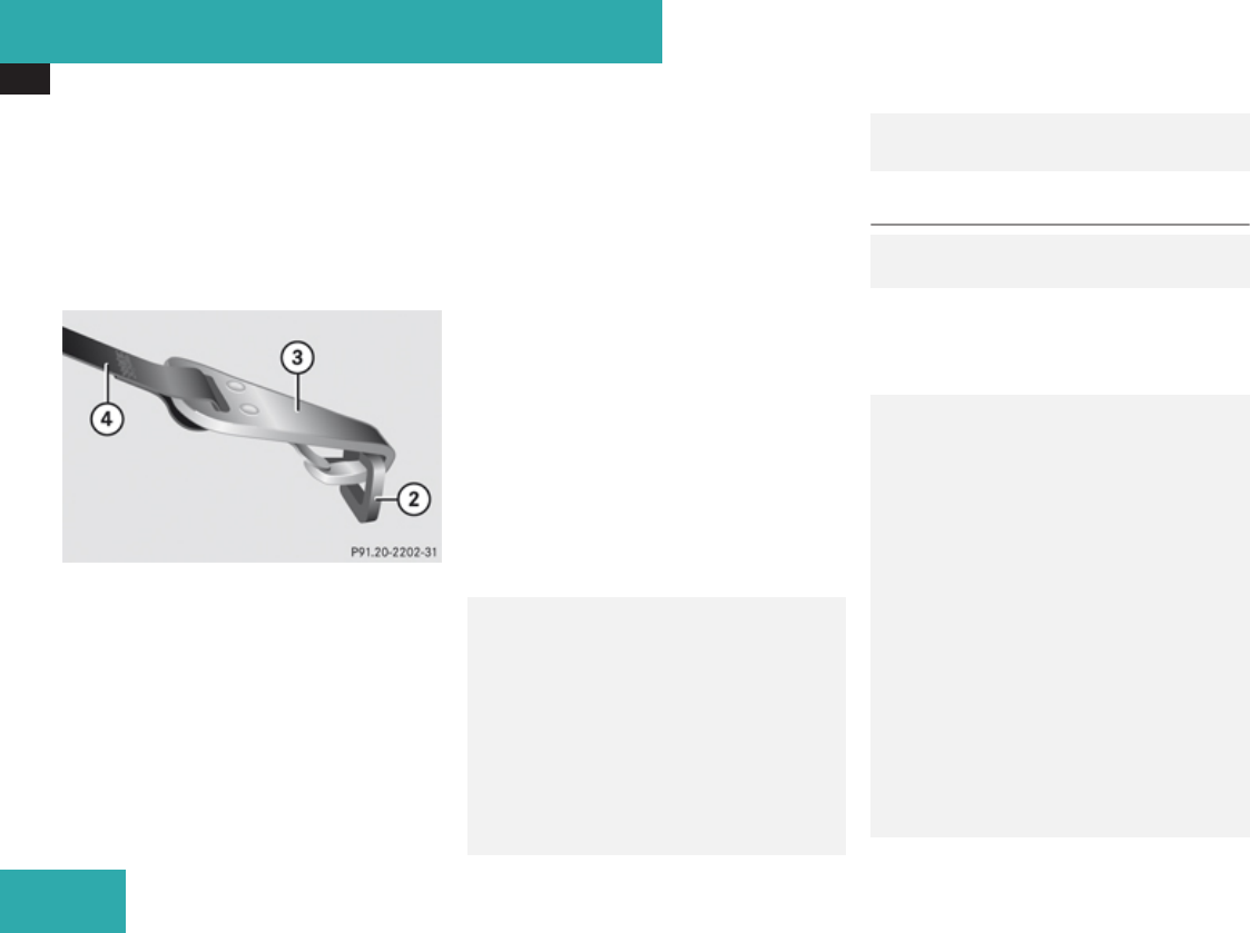
Occupant safety
66
XBring the rear power seat backrest to a fully
upright position (Y page 310).
XRemove anchorage ring cover 1 from the
anchorage ring of the seat on which a child
seat is to be installed.
XStore anchorage ring cover 1 in a
convenient place (e.g. glove box).
2Anchorage ring
3Hook
4Top tether strap
XGuide top tether strap 4 between the
head restraint and top of the seat backrest.
The head restraint must be positioned such
that top tether strap 4 can pass freely
between the head restraint and top of the
seat backrest.
XMake sure top tether strap 4 is not
twisted.
XSecurely fasten hook 3, which is part of
top tether strap 4, to anchorage ring 2.
XFor safety, make sure hook 3 is attached
to anchorage ring 2 beyond the safety
catch, as illustrated.
Once hook 3 is attached, the child restraint
itself can be secured.
XInstall the child restraint system and
tighten top tether strap 4 according to the
child restraint manufacturer’s instructions.
After removing the child restraint system and
top tether strap 4.
XReinstall anchorage ring cover 1.
GWarning!
Vehicles with rear power seats: Never
adjust the rear seat position after installing
the child restraint. Adjusting the rear seat
position after installing the child restraint
could damage the child restraint and/or
introduce undesirable slack or tension into
the seat belt and loosen or misposition the
child restraint, lessening the effectiveness
of the child restraint and thus increasing
the chance or severity of injury in an
accident.
Child seat anchors – LATCH-type
GObserve Safety notes, see
page 62.
This vehicle is equipped with two LATCH-type
anchors (at each of the rear outer seats) for
the installation of a LATCH-type child seat
with matching mounting fittings.
GWarning!
Children too big for a toddler restraint must
ride in seats using regular seat belts.
Position shoulder belt across chest and
shoulder, not face or neck.
A booster seat may be necessary to achieve
proper seat belt positioning for children
over 41 lb (18 kg) until they reach a height
where a lap/shoulder belt fits properly
without a booster.
Install child seat according to
manufacturer’s instructions.
The child seat must be firmly attached to
the right and left side anchors.
An incorrectly mounted child seat may
come loose during an accident which could
result in serious injury or death to the child.
Safety and security
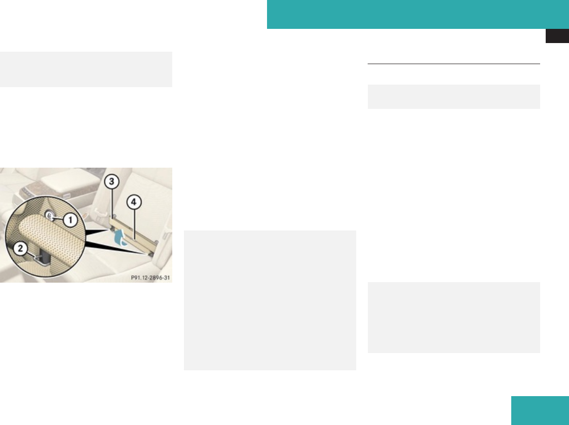
Occupant safety
67
Damaged or impact damaged child seats or
child seat mounting fittings must be
replaced.
Non-LATCH-type child seats may also be used
and can be installed using the vehicle’s seat
belt system. Install child seat according to the
manufacturer’s instructions.
The LATCH-type anchors are covered with
upholstery blends.
1Indicates the position of the anchors
2Anchors
3Upholstery blend
4Installation device
XBring the rear power seat backrest to a fully
upright position (Y page 310).
XFold upholstery blend 3 upward to access
anchors 2.
XTurn installation device 4 to a vertical
position so that upholstery blend 3 does
not fold down.
XInstall a LATCH-type child seat according
to the manufacturer’s instructions.
A rigid connection between the child seat
and the body of the vehicle is established.
! Make sure the seat belt for the center
seat can operate freely with a child seat
installed.
GWarning!
Vehicles with rear power seats: Never
adjust the rear seat position after installing
the child restraint. Adjusting the rear seat
position after installing the child restraint
could damage the child restraint and/or
introduce undesirable slack or tension into
the seat belt and loosen or misposition the
child restraint, lessening the effectiveness
of the child restraint and thus increasing
the chance or severity of injury in an
accident.
Child safety
Override switch
GObserve Safety notes, see
page 62.
You can disable select functions in the rear
passenger compartment for added safety (for
instance when you have children riding in the
rear passenger compartment).
You can disable the following functions in the
rear passenger compartment:
Rrear door window operation
Radjustment of front passenger seat from
the rear
Rrear center console lighter
Rsunblinds for panorama roof
Rrear window sunshade and rear side
window sunshades
GWarning!
Activate the override switch when children
are riding in the back seats of the vehicle.
The children may otherwise injure
themselves, e.g. by becoming trapped in
the window opening.
Safety and security
Z
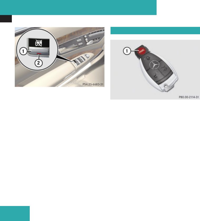
Panic alarm
68
1Override switch
2Indicator lamp
XActivating: Press override switch 1.
Indicator lamp 2 comes on.
The functions in the rear are disabled.
It is still possible to operate the rear door
windows using the switches located on the
door control panel of the driver’s door.
XDeactivating: Press override switch 1
again.
Indicator lamp 2 goes out.
The functions in the rear are enabled again.
For more information on power windows, see
the “Controls in detail” section
(Y page 334).
Panic alarm
1Â button
iUSA only:
This device complies with Part 15 of the
FCC Rules. Operation is subject to the
following two conditions:
1. This device may not cause harmful
interference, and
2. this device must accept any
interference received, including
interference that may cause undesired
operation.
Any unauthorized modification to this
device could void the user’s authority to
operate the equipment.
iCanada only:
This device complies with RSS-210 of
Industry Canada. Operation is subject to
the following two conditions:
1. This device may not cause interference,
and
2. this device must accept any
interference received, including
interference that may cause undesired
operation of the device.
Any unauthorized modification to this
device could void the user’s authority to
operate the equipment.
XActivating: Press and hold button 1 for at
least 1 second.
An audible alarm and flashing exterior
lamps will operate briefly.
XDeactivating: Press button 1 again.
or
XInsert the SmartKey in the starter switch.
or
XPress the KEYLESS-GO start/stop button.
The SmartKey with KEYLESS-GO must be
inside the vehicle.
Safety and security

Driving safety systems
69
Driving safety systems
Introduction
This section contains information about the
following driving safety systems:
RABS (Antilock Brake System)
RAdaptive Brake
RAdaptive Brake Lights
RBAS (Brake Assist System)
RBAS Plus (Brake Assist System Plus)
REBP (Electronic Brake Proportioning)
RESP® (Electronic Stability Program)
RPRE-SAFE® Brake (Preventive Occupant
Safety System)
iIn winter operation, the maximum
effectiveness of most of the driving
systems described in this section is only
achieved with winter tires, or snow chains
as required.
Safety notes
GWarning!
The following factors increase the risk of
accidents:
RExcessive speed, especially in turns
RWet and slippery road surfaces
RFollowing another vehicle too closely
The driving safety systems described in this
section cannot reduce these risks or
prevent the natural laws of physics from
acting on the vehicle. They cannot increase
braking or steering efficiency beyond that
afforded by the condition of the vehicle
brakes and tires or the traction afforded.
Only a safe, attentive, and skillful driver can
prevent accidents.
The capabilities of a vehicle equipped with
the driving safety systems described in this
section must never be exploited in a
reckless or dangerous manner which could
jeopardize the user’s safety or the safety of
others.
Always adjust your driving style to the
prevailing road and weather conditions and
keep a safe distance to other road users
and objects on the street.
If a driving system malfunctions, other
driving safety systems may also switch off.
Observe indicator and warning lamps that
may come on as well as messages in the
multifunction display that may appear.
ABS
GObserve Safety notes, see
page 69.
GWarning!
Do not pump the brake pedal. Use firm,
steady brake pedal pressure instead.
Pumping the brake pedal defeats the
purpose of the ABS and significantly
reduces braking effectiveness.
The Antilock Brake System (ABS) regulates
the brake pressure so that the wheels do not
lock during braking. This allows you to
maintain the ability to steer your vehicle.
The ABS is functional above a speed of
approximately 5 mph (8 km/h) independent
of road surface conditions.
On slippery road surfaces, the ABS will
respond even to light brake pressure.
The - indicator lamp in the instrument
cluster comes on when you switch on the
Safety and security
Z

Driving safety systems
70
ignition. It goes out when the engine is
running.
Braking
At the instant one of the wheels is about to
lock up, a slight pulsation can be felt in the
brake pedal, indicating that the ABS is in the
regulating mode.
XKeep firm and steady pressure on the brake
pedal while you feel the pulsation.
Continuous, steady brake pedal pressure
yields the advantages provided by the ABS,
namely braking power and the ability to steer
the vehicle.
The pulsating brake pedal can be an
indication of hazardous road conditions and
functions as a reminder to take extra care
while driving.
Emergency brake maneuver
XKeep continuous full pressure on the brake
pedal.
GWarning!
If the ABS malfunctions, other driving
safety systems such as the BAS or the
ESP® are also switched off. Observe
indicator and warning lamps that may come
on as well as messages in the multifunction
display that may appear.
If the ABS malfunctions, the wheels may
lock during hard braking, reducing steering
capability and extending the braking
distance.
For more information, see “What to do
if …?” (Y page 549).
BAS
GObserve Safety notes, see
page 69.
The Brake Assist System (BAS) operates in
emergency situations. If you apply the brakes
very quickly, the BAS automatically provides
full brake boost, thereby potentially reducing
the braking distance.
XApply continuous full braking pressure until
the emergency braking situation is over.
The ABS will prevent the wheels from
locking.
When you release the brake pedal, the brakes
function again as normal. The BAS is then
deactivated.
GWarning!
If the BAS malfunctions, the brake system
still functions, but without the additional
brake boost available that the BAS would
normally provide in an emergency braking
maneuver. Therefore, the braking distance
may increase.
BAS Plus
The Brake Assist System Plus (BAS Plus)
operates in emergency braking situations and
uses radar sensors to assess the traffic
situation. BAS Plus assists you in braking at
speeds above approximately 20 mph
(30 km/h).
When traveling in Canada in a vehicle not
registered in Canada, you must switch off the
radar sensor system (Y page 253). Canadian
law does not permit the use of the radar
sensor system for vehicles from outside of
Canada.
When you switch off the radar system, the
following functions are deactivated:
RBAS Plus
RPRE-SAFE® Brake (Y page 76)
RDISTRONIC Plus (Y page 360)
RPark Assist (Y page 379)
RBlind Spot Assist (Y page 392)
RAdvanced Parking Guidance (Y page 383)
Safety and security

Driving safety systems
71
GWarning!
BAS Plus is a convenience system designed
to assist the driver during vehicle
operation. The responsibility for the vehicle
speed and the distance to the vehicle
ahead, including most importantly brake
operation to assure safe stopping distance,
always remains with the driver.
Always pay attention to traffic conditions
even while BAS Plus is switched on.
Otherwise, you may not be able to
recognize dangerous situations until it is
too late and could cause an accident
resulting in personal or fatal injury to you
or others.
iThis device has been approved by the FCC
as a “Vehicular Radar System”. The radar
sensor is intended for use in an automotive
radar system only. Removal, tampering, or
altering of the device will void any
warranties, and is not permitted by the
FCC. Do not tamper with, alter, or use in
any non-approved way.
Any unauthorized modification to this
device could void the user’s authority to
operate the equipment.
BAS Plus detects obstacles that are in your
driving path for a sufficient period of time to
permit the system to recognize these
obstacles. If you approach the detected
obstacle quickly, BAS Plus calculates the
level of brake power boost appropriate for the
circumstance to supply when the driver
applies the brakes.
When you step quickly on the brake pedal in
an emergency braking situation, BAS Plus
automatically regulates the brake power
boost to a level that is suitable for the traffic
situation.
If BAS Plus requires a particularly high brake
power boost, PRE-SAFE® is activated at the
same time.
XKeep constant pressure on the brake pedal
until the emergency braking situation is
over.
During this process, the ABS prevents the
wheels from locking up.
The brakes will resume normal operation
after
Rthe brake pedal is released
Rno obstacles are detected in your path
Rthe system no longer senses a risk of a
collision
BAS Plus is then deactivated.
BAS Plus can react to stationary obstacles
such as standing or parked vehicles at road
speeds of up to approximately 40 mph
(70 km/h).
BAS Plus can only assist you when the radar
sensors are switched on and functional. You
can check whether the sensors are active by
switching on DISTRONIC Plus (Y page 360)
or using the Radar sensors function
(Y page 253) in the instrument cluster
control system.
GWarning!
BAS Plus will only respond with brake
assistance if it has clearly detected an
object. Detection can be impeded by
Rdirty or covered sensors
Rsnowfall or heavy rain
Rdisturbance from other radar sources
Rstrong radar reflection such as in parking
garages
BAS Plus uses radar signals that are not
reflected well by narrow objects and
absorptive materials. For this reason BAS
Plus will not react to persons, animals, and
approaching traffic or cross-traffic.
BAS Plus may not detect narrow vehicles
driving in front of you, such as motorcycles
Safety and security
Z

Driving safety systems
72
and vehicles driving offset from your
vehicle center.
After a hard collision or damage to the front
of the vehicle from an accident, have the
adjustment and operation of the radar
sensors checked by an authorized Mercedes-
Benz Center.
If BAS Plus is not available due to a radar
sensor malfunction, the braking system will
continue to function normally with full brake
boost and full standard BAS function.
Adaptive Brake
Adaptive Brake provides a high level of
braking safety as well as increased braking
comfort. It is coupled with the ABS, the
ESP® and the BAS. Adaptive Brake takes
driver and vehicle characteristics into
consideration, thus achieving an optimal
braking effect.
For more information on the brake system,
see (Y page 476).
Adaptive Brake Lights
iThis function is only available for the
S 600 and the S 65 AMG (USA only).
The brake lamps flash in quick intervals while
you are braking hard at a speed of more than
30 mph (50 km/h) or when you are braking
with the aid of BAS or BAS Plus. This helps to
alert drivers behind you.
If you bring the car to a complete stop by hard
braking at a speed of more than 40 mph
(70 km/h), the hazard warning flasher
automatically comes on as soon as the
vehicle is at a standstill. While the vehicle is
stationary, the brake lamps are continuously
lit up. Once you drive faster than 6 mph
(10 km/h) afterward, the hazard warning
flasher goes out.
EBP
GObserve Safety notes, see
page 69.
The Electronic Brake Proportioning (EBP)
enhances braking effectiveness by allowing
the rear brakes to supply a greater proportion
of the braking effort in straight line braking
without a loss of vehicle stability.
GWarning!
If the EBP malfunctions, the brake system
will still function with full brake boost.
However, the rear wheels could lock up
during emergency braking situations, for
example. You could lose control of the
vehicle and cause an accident.
Adapt your driving style to the changed
driving characteristics.
Safety and security

Driving safety systems
73
ESP®
GObserve Safety notes, see
page 69.
The Electronic Stability Program (ESP®) is
operational as soon as the engine is running
and monitors the vehicle’s traction (force of
adhesive friction between the tires and the
road surface) and handling.
The ESP® recognizes when a wheel is
spinning or if the vehicle starts to skid. By
applying brakes to individual wheels and by
limiting the engine output, the ESP® works to
stabilize the vehicle. The ESP® is especially
useful while driving off and on wet or slippery
road surfaces. The ESP® also stabilizes the
vehicle during braking and steering
maneuvers.
The ESP® warning lamp v in the
instrument cluster comes on when you switch
on the ignition. It goes out when the engine
is running.
The ESP® warning lamp v in the
instrument cluster flashes when the ESP® is
engaged.
GWarning!
Never switch off the ESP® when you see the
ESP® warning lamp v flashing in the
instrument cluster. In this case proceed as
follows:
RWhen driving off, apply as little throttle
as possible.
RWhile driving, ease up on the accelerator
pedal.
RAdapt your speed and driving style to the
prevailing road conditions.
Failure to observe these guidelines could
cause the vehicle to skid. The ESP® cannot
prevent accidents resulting from excessive
speed.
! Vehicles with 4MATIC:
Only conduct operational or performance
tests on a two-axle dynamometer. If such
tests are necessary, contact an authorized
Mercedes-Benz Center. You could
otherwise seriously damage the brake
system or the transfer case which is not
covered by the Mercedes-Benz Limited
Warranty.
! Vehicles with 4MATIC:
Because the ESP® operates automatically,
the engine and ignition must be shut off
(SmartKey in starter switch position 0 or
1 or KEYLESS-GO start/stop button in
position 0 or 1) when the electronic parking
brake is being tested on a brake test
dynamometer.
Active braking action through the ESP®
may otherwise seriously damage the brake
system which is not covered by the
Mercedes-Benz Limited Warranty.
! Vehicles without 4MATIC:
Because the ESP® operates automatically,
the engine and ignition must be shut off
(SmartKey in starter switch position 0 or
1 or KEYLESS-GO start/stop button in
position 0 or 1) when the electronic parking
brake is being tested on a brake test
dynamometer or when the vehicle is being
towed with one axle raised.
Active braking action through the ESP®
may otherwise seriously damage the brake
system which is not covered by the
Mercedes-Benz Limited Warranty.
! The ESP® will only function properly if you
use wheels of the recommended tire size
Safety and security
Z
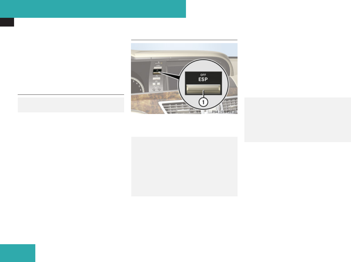
Driving safety systems
74
as specified in the “Technical data” section
of this Operator’s Manual.
iThe DISTRONIC Plus and cruise control
switch off automatically when the ESP®
engages.
Electronic Traction System
(ETS/4-ETS)
GObserve Safety notes, see
page 69.
The ETS (Electronic Traction System) and
4-ETS (four-wheel Electronic Traction
System, vehicles with 4MATIC only) are
components of the ESP®. The ETS/4-ETS
improves the vehicle’s ability to utilize
available traction, especially under slippery
road conditions by applying the brakes to a
spinning wheel. Vehicles with 4MATIC also
transfer more power to the wheel(s) with
traction.
When you switch off the ESP®, the
ETS/4-ETS is still enabled.
Switching off the ESP®
1ESP® switch
Switching off the ESP® (except S 63 AMG)
GWarning!
The ESP® should not be switched off during
normal driving other than in the
circumstances described below. Disabling
the system will reduce vehicle stability in
driving maneuvers.
Do not switch off the ESP® when a spare
wheel is mounted.
To improve the vehicle’s traction, switch off
the ESP® in driving situations in which it
would be advantageous to have the drive
wheels spin and thus cut into surfaces for
better grip such as:
Rwhen driving with snow chains
Rin deep snow
Rin sand or gravel
GWarning!
Switch on the ESP® immediately if the
aforementioned circumstances do not
apply anymore. Otherwise the ESP® will not
stabilize the vehicle when it is starting to
skid or a wheel is spinning.
When you switch off the ESP®,
Rthe ESP® does not stabilize the vehicle
Rthe engine output is not limited, which
allows the drive wheels to spin and thus cut
into surfaces for better grip
Rthe ETS/4-ETS will still apply the brakes to
a spinning wheel
Rthe ESP® continues to operate when you
are braking
Safety and security

Driving safety systems
75
Ryou cannot activate the cruise control or
the DISTRONIC Plus
Rthe cruise control or the DISTRONIC Plus
switch off if activated
iWhen the ESP® is switched off and one or
more drive wheels are spinning, the ESP®
warning lamp v in the instrument
cluster flashes. However, the ESP® will
then not stabilize the vehicle.
XWith the engine running, press ESP® switch
1 until the ESP® warning lamp v in the
instrument cluster comes on.
The ESP® is switched off.
GWarning!
When the ESP® warning lamp v is
illuminated continuously, the ESP® is
switched off or is not operational due to a
malfunction. Vehicle stability in standard
driving maneuvers is reduced.
Adapt your speed and driving to the
prevailing road conditions and to the non-
operating status of the ESP®.
! Avoid spinning of a drive wheel for an
extended period with the ESP® switched
off. This may cause serious damage to the
drivetrain which is not covered by the
Mercedes-Benz Limited Warranty.
Switching off the ESP® (S 63 AMG only)
GWarning!
The ESP® should not be switched off during
normal driving.
Disabling of the system will result in the
following:
Rno restriction to engine torque
Rloss of system supported traction control
“ESP® OFF” is designed for driving on
closed tracks when the vehicle’s natural
oversteer and understeer characteristics
are desired and requires a highly skilled and
experienced driver able to handle these
critical driving situations.
You could lose control of your vehicle and
cause an accident.
Please be aware of these limits when you
switch off the ESP®.
Do not switch off the ESP® when a spare
wheel is mounted.
When you switch off the ESP®,
Rthe ESP® does not stabilize the vehicle
Rthe engine output is not limited, which
allows the drive wheels to spin
Rthe ETS will still apply the brakes to a
spinning wheel
Rthe ESP® operates while you are braking
Ryou cannot activate the cruise control or
the DISTRONIC Plus
Rthe cruise control or the DISTRONIC Plus
switch off if activated
iWhen the ESP® is switched off and one or
more drive wheels are spinning, the ESP®
warning lamp v in the instrument
cluster flashes. However, the ESP® will
then not stabilize the vehicle.
XWith the engine running, press ESP® switch
1 until the ESP® warning lamp v in the
instrument cluster comes on.
The ESP® is switched off.
GWarning!
When the ESP® warning lamp v is
illuminated continuously, the ESP® is
switched off or is not operational due to a
Safety and security
Z

Driving safety systems
76
malfunction. Vehicle stability in standard
driving maneuvers is reduced.
Adapt your speed and driving to the
prevailing road conditions and to the non-
operating status of the ESP®.
! Avoid spinning of a drive wheel for an
extended period with the ESP® switched
off. This may cause serious damage to the
drivetrain which is not covered by the
Mercedes-Benz Limited Warranty.
Switching on the ESP®
XPress ESP® switch 1 until the ESP®
warning lamp v in the instrument
cluster goes out.
You are now again in normal driving mode
with the ESP® switched on.
PRE-SAFE® Brake
In vehicles equipped with DISTRONIC Plus,
the PRE-SAFE® Brake can assist you in
minimizing the risk of a rear-end collision with
a vehicle in front of you and in reducing the
severity of an accident. At speeds above
approximately 20 mph (30 km/h), it will
Rwarn you of a possible collision
Rautomatically begin to brake the vehicle
lightly in a speed range of up to 112 mph
(180 km/h)
Ractivate preventative occupant safety
measures (PRE-SAFE®) (Y page 59)
GWarning!
PRE-SAFE® Brake is a convenience system
designed to assist the driver during vehicle
operation. The responsibility for the vehicle
speed and the distance to the vehicle
ahead, including most importantly brake
operation to assure safe stopping distance,
always remains with the driver.
Always pay attention to traffic conditions
even while PRE-SAFE® is switched on.
Otherwise, you may not be able to
recognize dangerous situations until it is
too late and could cause an accident
resulting in personal or fatal injury to you
or others.
iUSA only:
This device has been approved by the FCC
as a “Vehicular Radar System”. The radar
sensor is intended for use in an automotive
radar system only. Removal, tampering, or
altering of the device will void any
warranties, and is not permitted by the
FCC. Do not tamper with, alter, or use in
any non-approved way.
Any unauthorized modification to this
device could void the user’s authority to
operate the equipment.
iCanada only:
This device complies with RSS-210 of
Industry Canada. Operation is subject to
the following two conditions:
1. This device may not cause interference,
and
2. this device must accept any
interference received, including
interference that may cause undesired
operation of the device.
Removal, tampering, or altering of the
device will void any warranties, and is not
Safety and security

Driving safety systems
77
permitted. Do not tamper with, alter, or use
in any non-approved way.
Any unauthorized modification to this
device could void the user’s authority to
operate the equipment.
PRE-SAFE® will only assist you by initiating
braking automatically when the driver and
front passenger have their seat belts
fastened.
Using the radar sensors, PRE-SAFE® Brake
detects obstacles that are in your driving path
for a sufficient period of time for the system
to recognize it. If you approach a vehicle and
PRE-SAFE® Brake has established that the
distance to the vehicle ahead at your current
speed is so close that PRE-SAFE® Brake will
not be capable of slowing the vehicle
sufficiently, the system will initially warn you
visually and acoustically.
When traveling in Canada in a vehicle not
registered in Canada, you must switch off the
radar sensor system (Y page 253). Canadian
law does not permit the use of the radar
sensor system for vehicles from outside of
Canada.
When you switch off the radar system, the
following functions are deactivated:
RPRE-SAFE® Brake
RBAS Plus (Y page 70)
RDISTRONIC Plus (Y page 360)
RPark Assist (Y page 379)
RBlind Spot Assist (Y page 392)
RAdvanced Parking Guidance (Y page 383)
GWarning!
PRE-SAFE® Brake will only respond with
brake assistance if it has clearly detected
an object. Detection can be impeded by
Rdirty or covered sensors
Rsnowfall or heavy rain
Rdisturbance from other radar sources
Rstrong radar reflection such as in parking
garages
PRE-SAFE® uses radar signals that are not
reflected well by narrow objects and
absorptive materials. For this reason PRE-
SAFE® will not react to persons, animals,
and approaching traffic or cross-traffic.
PRE-SAFE® may not detect narrow vehicles
driving in front of you, such as motorcycles
and vehicles driving offset from your
vehicle center.
When the distance to the forward vehicle is
too small, the distance warning lamp l in
the instrument cluster comes on. If you
approach the forward vehicle very quickly,
you will hear a warning signal.
If you do not apply the brakes yourself or
maneuver around a sensed obstacle, the
vehicle will brake lightly automatically. PRE-
SAFE® (Y page 59) is activated when the
distance to the vehicle ahead at your current
speed is so close that PRE-SAFE® Brake will
not be capable of slowing the vehicle
sufficiently.
GWarning!
PRE-SAFE® Brake brakes your vehicle with
a maximum of 13 ft/s2 (4 m/s2). This
corresponds to about 40% of the maximum
deceleration ability of your vehicle. This
automatic braking is intended only to
initiate the braking if the driver has not
already done so. The driver must apply the
brakes in order to prevent a collision.
PRE-SAFE® Brake applies the brake pedal
automatically which results in the brake
pedal moving. Therefore keep driver’s foot
Safety and security
Z

Driving safety systems
78
area clear at all times, including the area
under the brake pedal. Objects stored in
this area may impair pedal movement
which could interfere with the braking
ability of the PRE-SAFE® Brake.
Do not place your foot under the brake
pedal – your foot could become caught.
To maintain the proper distance to the vehicle
in front of you and thus prevent a rear-end
collision, you must apply the brakes yourself.
XBrake the vehicle immediately to avoid a
collision.
Under no circumstances should the driver
await the intermittent warning sound
before braking. Observe the following
warning note.
The intermittent warning sound ceases and
the distance warning lamp l goes out
when the necessary distance to the vehicle
ahead is again established.
GWarning!
An intermittent warning sounds and the
distance warning lamp l in the
instrument cluster is illuminated if PRE-
SAFE® Brake calculates that the distance
to the vehicle ahead and your vehicle’s
current speed indicate that PRE-SAFE®
Brake will not be capable of slowing the
vehicle sufficiently to maintain the preset
following distance, which creates a danger
of a collision.
Immediately brake your vehicle to increase
the distance between your vehicle and the
vehicle driving in front of you. The warning
sound is intended as a final caution that you
have not interceded with your own braking
inputs to avoid a potentially dangerous
situation. Do not wait for the operation of
the warning signal to intercede with your
own braking, as that will result in potentially
dangerous emergency braking which will
not always result in an impact being
avoided.
Tailgating increases the risk of an accident.
PRE-SAFE® Brake can react to stationary
obstacles such as standing or parked vehicles
at road speeds of up to approximately 40 mph
(70 km/h).
GWarning!
If you do not receive visual or acoustic
warning signals, PRE-SAFE® Brake has
either not recognized the collision risk, has
been deactivated or is malfunctioning.
Apply the brakes yourself to avoid a
collision.
XActivating and deactivating: Activate or
deactivate PRE-SAFE® Brake using the
instrument cluster control system
(Y page 250).
After the function has been activated,
indicator : appears on the left-hand
side of the multifunction display.
PRE-SAFE® Brake does not always clearly
interpret complex traffic situations. If a visual
and/or acoustic warning is issued in an
uncritical driving situation, or if the vehicle
brakes lightly, you can interrupt the PRE-
SAFE® Brake maneuver by pressing down all
the way on the accelerator pedal, using
kickdown, or releasing the brake pedal.
The PRE-SAFE® Brake maneuver is
terminated immediately when
Ryou avoid the obstacle by evasive steering
Ryou drive less than 9 mph (15 km/h)
Ran obstacle can no longer be identified
ahead of you
Rthe system no longer senses the risk of a
collision
Safety and security

Anti-theft systems
79
iPRE-SAFE® Brake will remain passive
while DISTRONIC Plus is switched on
(Y page 360).
After a hard collision or damage to the front
of the vehicle from an accident, have the
settings and operation of the radar sensors
checked by an authorized Mercedes-Benz
Center.
Anti-theft systems
Immobilizer
The immobilizer prevents unauthorized
persons from starting your vehicle.
When leaving the vehicle, always take the
SmartKey with you and lock the vehicle. The
engine can be started by anyone with a valid
SmartKey that is left inside the vehicle.
Activating
XWith SmartKey: Remove the SmartKey
from the starter switch.
XWith KEYLESS-GO: Turn off the engine and
open the driver’s door.
Deactivating
XSwitch on the ignition.
iStarting the engine will also deactivate
the immobilizer.
In the event that the engine cannot be
started (yet the vehicle’s battery is
charged), the system is not operational.
Contact an authorized Mercedes-Benz
Center or call 1-800-FOR-MERCedes (in the
USA), or 1-800-387-0100 (in Canada).
Anti-theft alarm system
Once the alarm system has been armed, a
visual and audible alarm is triggered when
someone opens
Ra door
Rthe trunk
Rthe hood
The alarm will stay on even if the activating
element (a door, for example) is immediately
closed.
The alarm system will also be triggered when
Rthe vehicle is opened with the mechanical
key
Ra door is opened from the inside
To cancel the alarm after it has been
triggered, see “Canceling the
alarm” (Y page 80).
iIf the alarm stays on for more than
30 seconds, a call to the Response Center
is initiated automatically by the Tele Aid
system provided that you have subscribed
to the Tele Aid service and that it has been
activated properly, and that the necessary
mobile phone, power supply and GPS
coverage are available.
Safety and security
Z
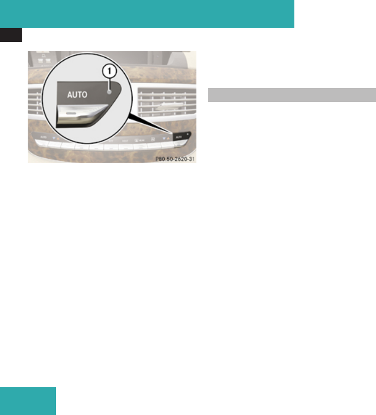
Anti-theft systems
80
1Indicator lamp
XArming: Lock the vehicle with the
SmartKey or with KEYLESS-GO.
The turn signal lamps flash three times to
indicate that the vehicle is locked. Indicator
lamp 1 flashes to indicate that the alarm
system is armed.
iIf the turn signal lamps do not flash three
times, a door or the trunk may not be
properly closed.
Close the respective element.
XDisarming: Unlock the vehicle with the
SmartKey or with KEYLESS-GO.
The turn signal lamps flash once to indicate
that the alarm system is disarmed.
iThe vehicle will lock and the alarm system
will rearm automatically again after
approximately 40 seconds unless you open
a door or the trunk.
Canceling the alarm
To cancel the alarm, do one of the following:
XInsert the SmartKey in the starter switch.
XPress button k or j on the
SmartKey.
In vehicles with KEYLESS-GO:
XGrasp an outside door handle.
The SmartKey must be within 3 ft (1 m) of
the vehicle.
XPress the KEYLESS-GO start/stop button.
The SmartKey must be inside the vehicle.
Safety and security

81
Vehicle equipment .............................. 82
COMAND introduction ........................ 82
COMAND system settings ................. 95
COMAND navigation (introduction) ... 99
COMAND navigation system
(entering a destination) .................... 111
COMAND navigation system (Point
of interest entry) ............................... 132
COMAND navigation system (route
guidance) ........................................... 139
COMAND navigation system (dur-
ing route guidance) ........................... 145
COMAND navigation system (real-
time traffic) ....................................... 147
COMAND navigation system (des-
tination memory) .............................. 149
COMAND navigation system (last
destinations) ..................................... 154
COMAND telephone .......................... 155
COMAND FM/AM radio .................... 188
COMAND satellite radio ................... 193
COMAND audio CD/audio DVD/
MP3 .................................................... 199
COMAND AUX .................................... 210
COMAND video DVD ......................... 213
COMAND vehicle menu .................... 220
COMAND automatic climate control 227
COMAND seats .................................. 233
Instrument cluster control system .237
Voice Control introduction ............... 254
Voice Control navigation .................. 258
Voice Control telephone ................... 265
Voice Control address book ............. 270
Voice Control radio ........................... 273
Voice Control CD/DVD changer/
MP3 .................................................... 275
Voice Control command list ............ 277
Voice Control troubleshooting ........ 289
Voice Control individualization ........ 293
Control systems

COMAND introduction
82
Vehicle equipment
iThis Operator’s Manual describes all
features, standard or optional, potentially
available for your vehicle at the time of
purchase. Please be aware that your
vehicle might not be equipped with all
features described in this manual.
COMAND introduction
COMAND operating safety
COMAND (Cockpit Management and Data
System) is an information and operating
center for vehicle sound and communications
systems, including the radio and navigation
system, as well as other optional equipment
(satellite radio, telephone, etc.).
GWarning!
Any alteration of electronic components or
software can cause malfunctions.
Radio, satellite radio, amplifier, CD/DVD
changer, navigation module, telephone and
Voice Control Systems are interconnected.
Therefore, if one of the components is not
operational, or has not been removed/
replaced properly, the function of other
components could be impaired.
Such conditions might seriously impair the
operating safety of your vehicle.
We recommend to have any service work
on electronic components carried out by an
authorized Mercedes-Benz Center.
GWarning!
In order to avoid distraction which could
lead to an accident, the driver should enter
system settings while the vehicle is at a
standstill, and operate the system only
when permitted by road, weather and
traffic conditions.
Bear in mind that at a speed of just 30 mph
(approximately 50 km/h), your vehicle is
covering a distance of 44 feet
(approximately 14 m) every second.
COMAND supplies you with information to
help you select your route more easily and
guide you conveniently and safely to your
destination. For safety reasons, we
encourage the driver to stop the vehicle in
a safe place before answering or placing a
call, or consulting the COMAND screen to
read navigational maps, instructions, or
downloaded information.
GWarning!
While the navigation system provides
directional assistance, the driver must
remain focused on safe driving behavior,
especially attention to traffic and street
signs, and should utilize the system’s audio
cues while driving.
The navigation system does not supply any
information on stop signs, yield signs,
traffic regulations or traffic safety rules.
Their observance always remains in the
Control systems
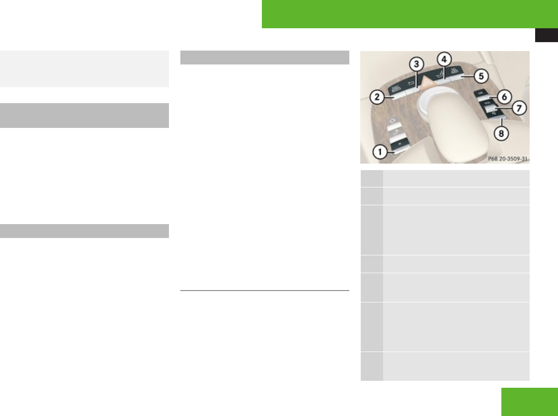
COMAND introduction
83
driver’s personal responsibility. DVD maps
do not cover all areas nor all routes within
an area.
Availability of functions while the
vehicle is in motion
For safety reasons, certain COMAND
functions are not available while the vehicle
is in motion or they are only available to a
limited extent. You will notice this, for
example, by the fact that certain menu items
cannot be selected or that the COMAND
display shows a corresponding message.
Switching COMAND on or off
XPress the o shortcut button in the
center console (Y page 83).
COMAND calls up the menu last selected.
iWhen you switch off COMAND, you also
switch off the currently playing audio
source. During a telephone call, you cannot
switch off COMAND.
COMAND components
In your vehicle, COMAND can be used to
operate:
Raudio functions
Rthe navigation system
Rthe telephone and communication
functions (SMS)
Rexternal audio and video sources
Rvideo DVD
Rvarious vehicle settings
COMAND consists of the following:
RCOMAND shortcut buttons
RCOMAND display
Rtelephone keypad
RCOMAND controller
COMAND shortcut buttons
iDuring rear view camera operation
(Y page 388) it is not possible to operate
the COMAND shortcut buttons.
Use the COMAND shortcut buttons to select
main functions directly.
Function
1P Favorite button (Y page 98)
2M Shortcut button for:
RCD/DVD/PCMCIA (Y page 206)
Rradio (Y page 189)
3L Back button (Y page 90)
4O Seat menu button
(Y page 233)
5N Shortcut button for:
Rtelephone (Y page 155)
Rnavigation (Y page 99)
6o COMAND on/off button
(Y page 83)
Control systems
Z
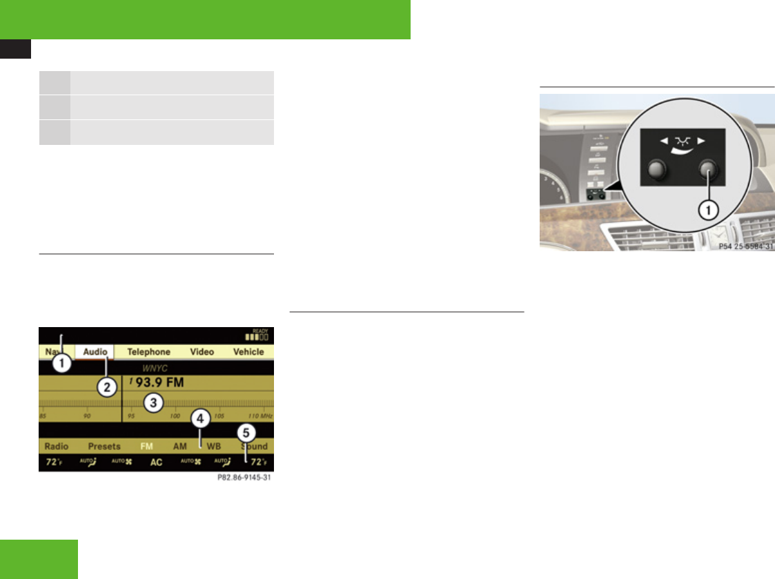
COMAND introduction
84
Function
7, Volume control (Y page 92)
8F Mute button (Y page 92)
Example:
XSwitching directly to Radio or CD
menu: Press M once or twice.
COMAND display
In the COMAND display, you will find the
function currently selected and the
corresponding menus. The COMAND display
is divided into several areas.
1Status line
2Main functions
3Main area
4Submenus
5Climate control settings
A white bar under main functions 2 indicates
the active area.
Once you have selected a main function 2,
main area 3 is active.
iThe layout of the menus may vary
depending on your vehicle’s equipment.
This manual shows the menus for a fully
equipped vehicle.
Instrument cluster multifunction
display
This section describes features and controls
via the COMAND controller, display and
shortcut buttons only.
Please refer to the “Instrument cluster
control system” section of this manual
(Y page 237) for function descriptions and
operation of the instrument cluster
multifunction display and multifunction
steering wheel buttons as they relate to
COMAND features described in this section.
Adjusting COMAND display illumination
1Knob
XBrightening illumination: Turn knob 1
clockwise.
XDimming illumination: Turn knob 1
counterclockwise.
Control systems
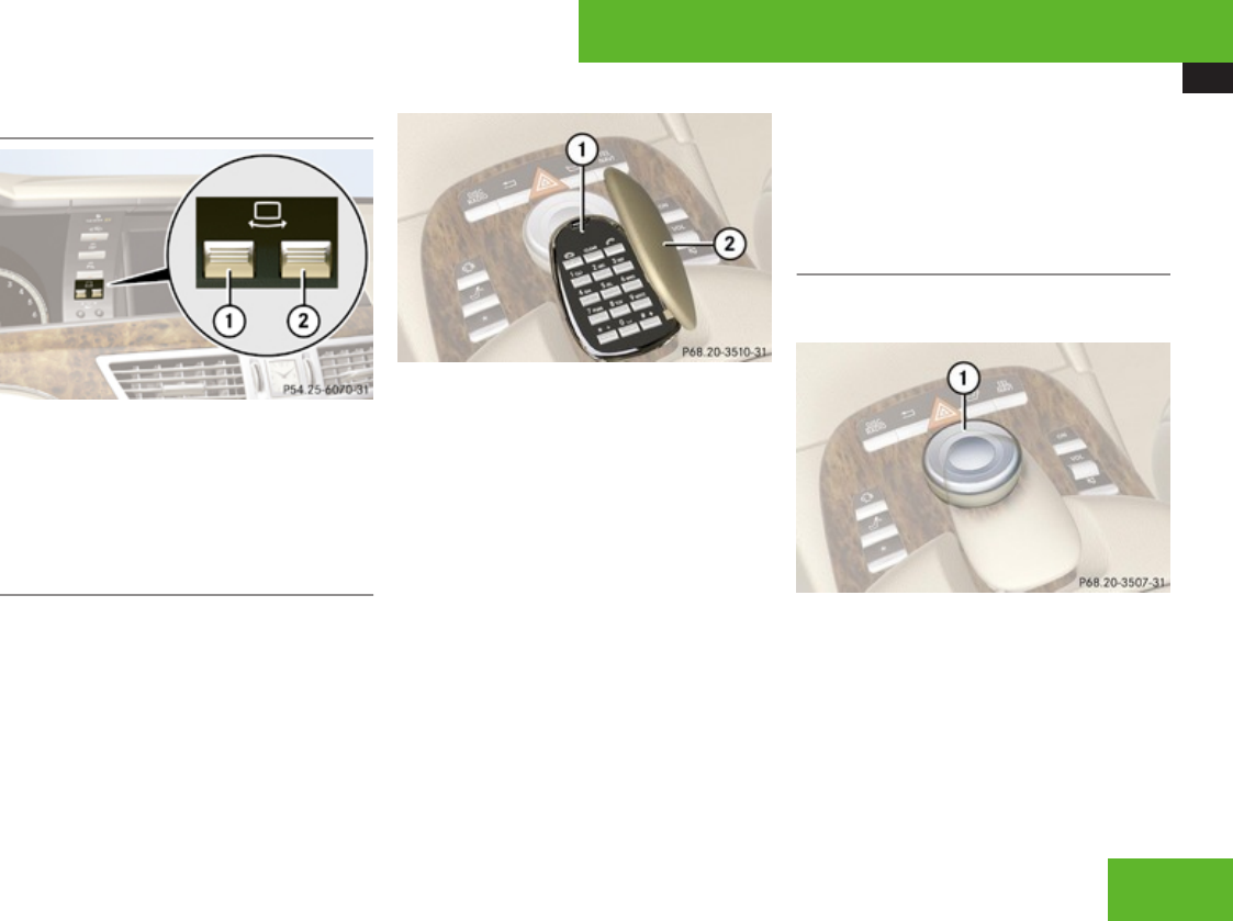
COMAND introduction
85
Swiveling COMAND display
1Button for swiveling display to the left
2Button for swiveling display to the right
You can swivel the COMAND display to the
left or right. The buttons are on the right-hand
side of the instrument cluster.
Telephone keypad
With the help of the telephone keypad, you
can use your mobile phone if it is inserted in
the cradle.
1Telephone keypad
1Folding cover
With the telephone keypad you can:
REnter and clear numbers and special
characters.
RReject, accept, connect and end calls
(Y page 155).
RSelect preset radio stations and enter the
frequency manually (Y page 191).
RSelect preset satellite radio stations and
enter the channel number (Y page 197).
RSelect a medium from the DVD changer
(Y page 207).
RSelect a track from CD, DVD-Audio or MP3
(Y page 208).
RSelect a scene/chapter from a video DVD
(Y page 217).
RSelect a street in the navigation entry
(Y page 120).
COMAND controller
Use the COMAND controller to select menu
functions shown on the COMAND display.
1COMAND controller
You can operate the COMAND controller as
follows:
Rpress briefly or press and hold
Rrotate to the left or right
Rslide to the left, right, up, down or
diagonally
Control systems
Z
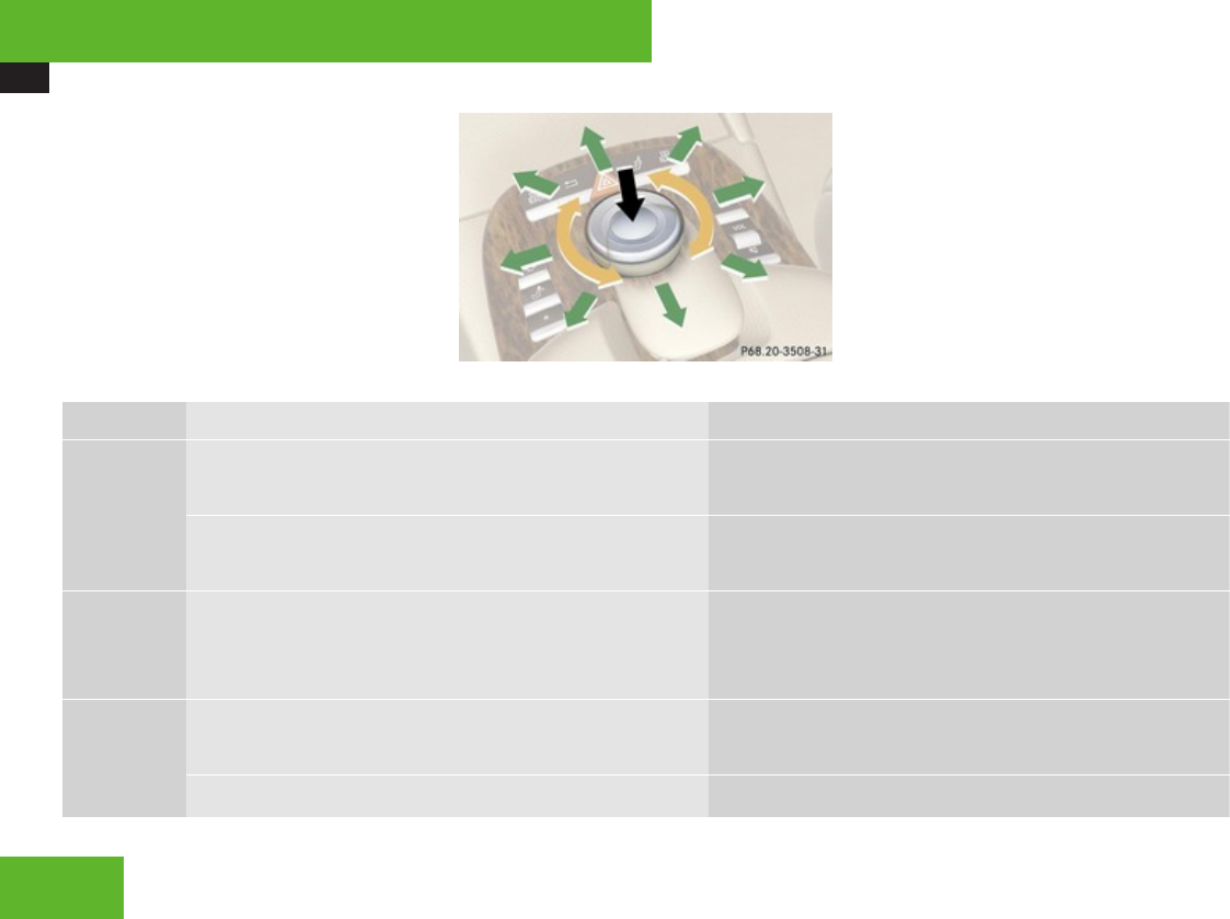
COMAND introduction
86
In this way, you can move through the menus,
select menu items or exit menus.
You can move through the menus either by
rotating or sliding the controller.
Operating COMAND controller
Symbol How to use the COMAND controller Function
nXPress briefly. RConfirming the selection of a menu item or list entry.
RExiting full-screen image with Navi.
XPress and hold until the selected action has been carried
out.
RSaving a station.
RAccepting a destination for navigation.
ymzXRotate. RMoving through vertical or horizontal menus.
RMoving through text.
RSelecting program settings.
qmrXSlide. RMoving through vertical menus.
RExiting horizontal menus.
XSlide and hold. RMoving through a navigation map.
Control systems

COMAND introduction
87
Symbol How to use the COMAND controller Function
ompXSlide. RMoving through horizontal menus.
RExiting vertical menus.
XSlide and hold. RFast forward or reverse for audio CD or audio DVD
playback.
RMoving through a navigation map.
wmxXSlide and hold. RMoving through a navigation map.
Operating COMAND
Menu overview
The table below shows the structure of the
main functions and their main menus.
Each main function has a main menu. Each
menu item in the main menu in turn has
several submenu items.
Commands/menus
Navi
RMap Display (Y page 108)
RMode (Y page 110)
Audio
RFM/AM Radio (Y page 188)
RSat Radio (Y page 193)
RCD (Y page 199)
RDVD-Audio (Y page 199)
RMP3 (Y page 199)
RAudio OFF (Y page 95)
RAUX (Y page 210)
Commands/menus
Telephone
RTelephone ON (Y page 155)
RAddress Book (Y page 174)
RTelephone OFF (Y page 158)
Control systems
Z
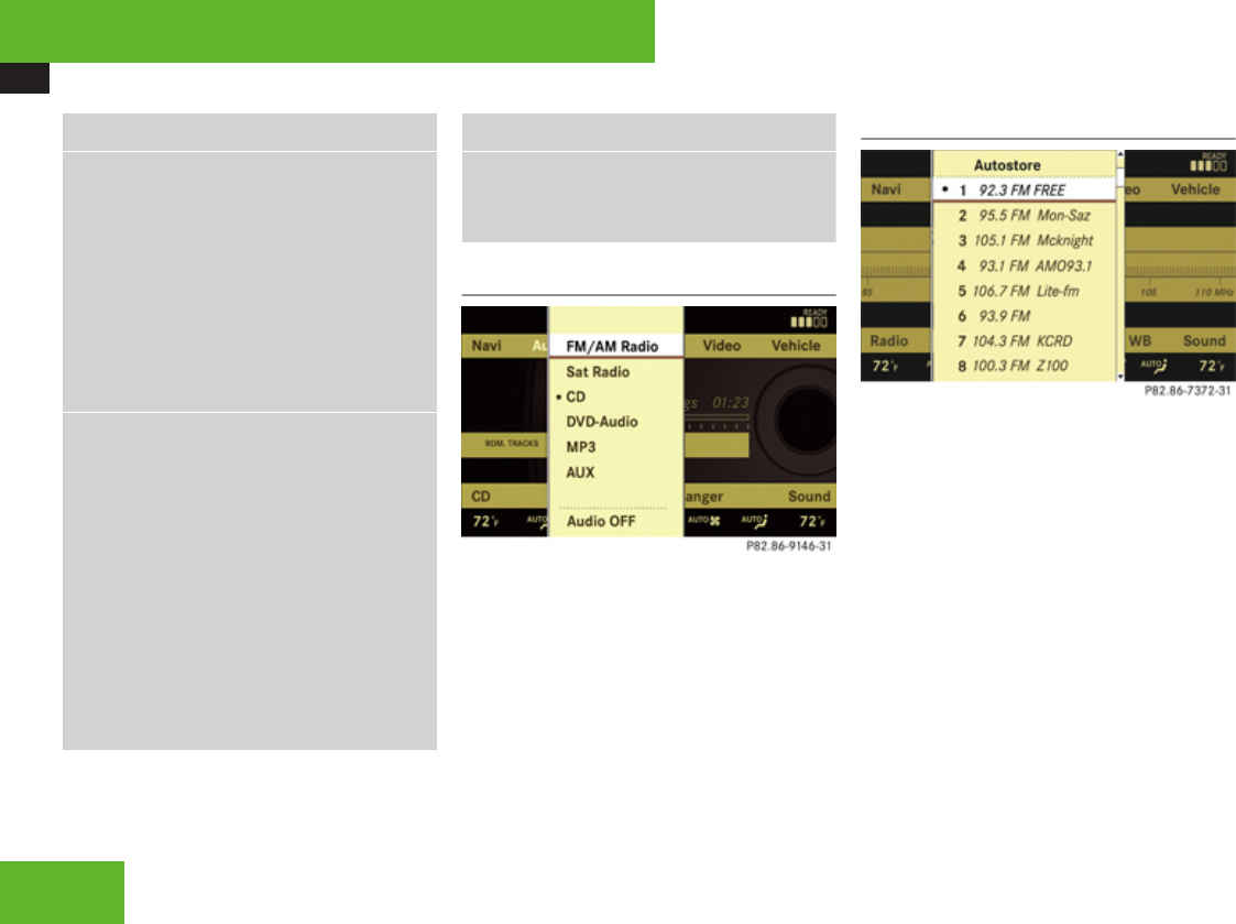
COMAND introduction
88
Commands/menus
Video DVD
RVideo DVD (Y page 213)
RSubmenu overview (Y page 214)
RSwitching to video DVD mode
(Y page 215)
RPause playback (Y page 216)
RDVD menu (Y page 217)
RVideo AUX (Y page 211)
Vehicle
RExterior Lighting Delayed Switch-off
(Y page 220)
RLocator Lighting (Y page 221)
RExterior Mirror Convenience Settings
(Y page 222)
RAutomatic Locking (Y page 222)
REasy Entry/Exit Feature (Y page 223)
RInterior Lighting Delayed Switch-off
(Y page 224)
RInterior Ambient Light (Y page 224)
Commands/menus
RRear Window Sunshade (Y page 225)
RTrunk Opening-height Restriction
(Y page 226)
Calling up the main menu
Example illustration: Audio main menu
You can call up the main menu of a main
function in the following manner:
XMoving to the main function line: Slide
qm.
XSelecting a main function: Slide omp or
rotate ymz.
XConfirming selection: Press n.
Vertical menus
XMoving through the menu: Slide qmr or
rotate ymz.
XSelecting a menu item: Press n.
XExiting a menu without making a
selection: Slide omp in the opposite
direction of the list orientation or press
back button L in the center console
(Y page 90).
Control systems
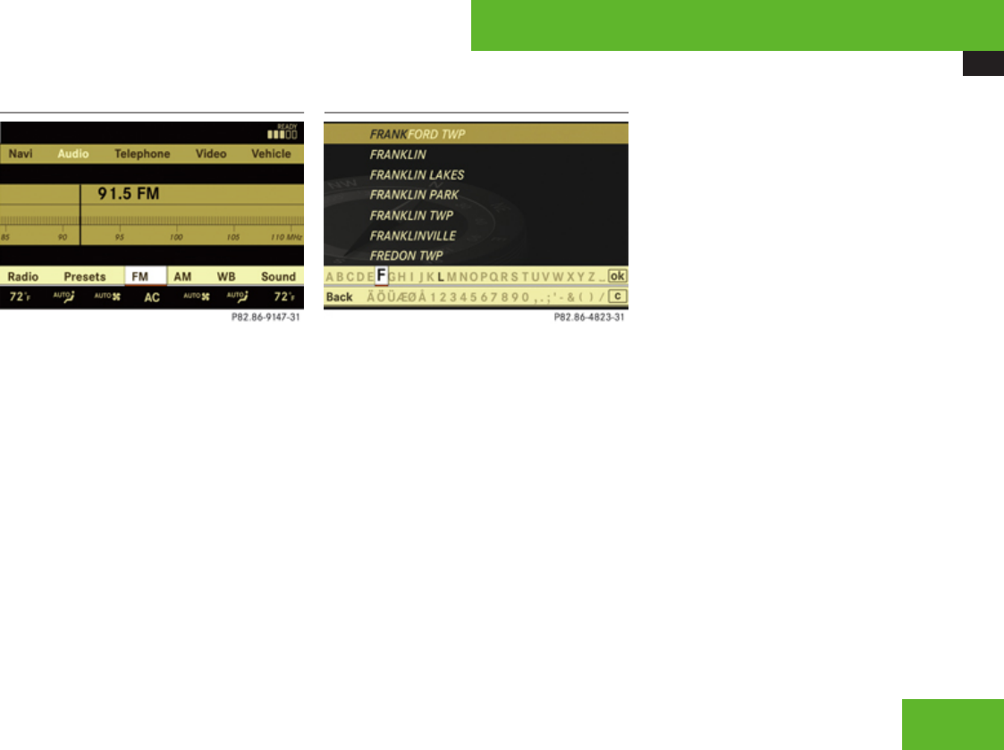
COMAND introduction
89
Horizontal menus
XMoving through the menu: Slide omp or
rotate ymz.
XSelecting a menu item: Press n.
XExiting a menu without making a
selection: Slide qmr in the opposite
direction of the list orientation or press
back button L.
Entering characters
Example illustration: Entering a navigation
destination
Selecting characters
XSlide omp or rotate ymz.
XConfirming selection: Press n.
COMAND completes your entry as soon as
it can be clearly identified. In this case, you
do not need to switch to the list.
Deleting individual characters
XSelect and press ) repeatedly in the
bottom line.
Deleting entire words or numbers
XPress and hold ) in the bottom line until
the word or number is deleted.
Exiting character entry
XSelect and press Back in the bottom line.
or
XPress back button L in the center
console (Y page 90).
Switching to the list
XSlide qm.
or
XSelect and press d in the second line
from the bottom.
XExiting list: Slide om to select Back.
Accepting first entry
XPress n until you exit the character entry
window.
Control systems
Z
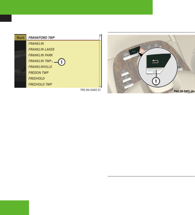
COMAND introduction
90
Selecting list item
Example illustration: List of cities for navigation
1Symbol for other selection options (e. g.
county)
XSelecting a line: Slide qmr or rotate
ymz.
XConfirming selection: Press n.
Additional selection options are available
for list entries featuring symbol 1. For
example, cities marked with symbol 1
indicate that the selected country has more
than one city featuring that name.
Confirming such a list entry opens up
another submenu.
Back button
1L Back button
XSwitching to the next highest menu:
Press back button L briefly.
COMAND switches to the next highest
menu level within the currently active
operating mode.
XSwitching to the main menu: Press and
hold back button L.
You will hear a signal, and COMAND
switches to the main menu of the currently
active operating mode.
Example of how to use COMAND
In the descriptions below, the main functions
always serve as the starting point for locating
the individual menu items.
Example: Audio £ Audio £ FM/AM
Radio £ Radio £ Save Station
iIn the COMAND display, you will see the
submenu previously called up for each
main menu.
If you already see one of the submenus on the
screen (e. g. the Audio £ Audio £
Radio submenu), it is not necessary to
perform the first steps.
The individual steps for the above-mentioned
example are described below.
XSwitching to the main function line:
Slide qm.
XSelecting Audio main function: Slide
omp or rotate ymz.
XConfirming selection: Press n.
The audio operating mode last selected
appears.
Control systems
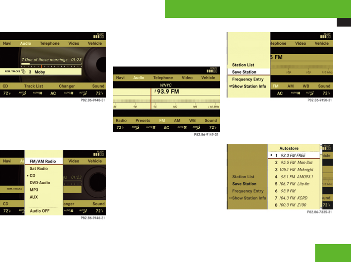
COMAND introduction
91
XSelecting Audio in the main menu: Slide
qm.
XConfirming selection: Press n.
A selection list with the functions of the
Audio main menu appears.
XSelecting FM/AM Radio: Slide qm or
rotate ymz.
XConfirming selection: Press n.
The FM/AM Radio menu appears.
XSelecting Radio: Slide mr and rotate
ymz.
XConfirming selection: Press n.
The Radio submenu appears.
XSelect Save Station from selection list by
rotating ymz or sliding qmr.
XPress n.
XSelect desired position.
Control systems
Z
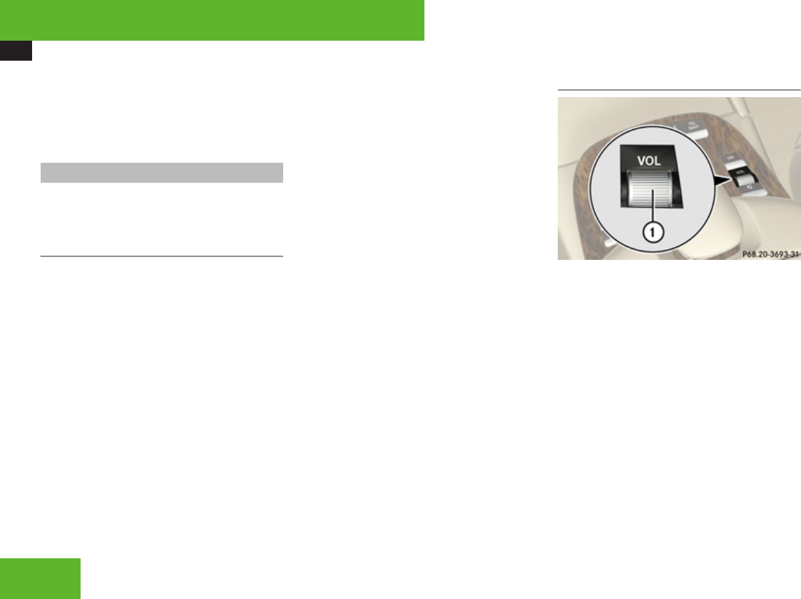
COMAND introduction
92
XConfirming selection: Press n.
The selected station is saved at the
designated position. The display switches
back to the Radio display.
Main menus of COMAND
iThe components and operating principles
of COMAND can be found on (Y page 82).
Sound
XMuting: Press shortcut button F in the
center console (Y page 83).
The sound of the current audio source is
switched on or is muted.
iWhen the sound is muted, you will see the
symbol F in the status line. When you
change the audio source, the sound is
automatically switched on. You will be able
to hear announcements from the
navigation system even when the sound is
muted.
Switching off navigation announcements
entirely
XCanceling navigation message: Briefly
press shortcut button F during an
announcement.
XSwitching off navigation messages:
Press and hold F during an
announcement until the announcement is
switched off.
You will see the message The driving
instructions have been muted. for a
short while.
iThe announcements remain switched off
even if you start a new route guidance or if
COMAND is switched off/on with the
o button. If you switch COMAND off by
removing the SmartKey from the starter
switch and then switch the ignition back on
after more than 3 minutes, the
announcements are automatically
switched back on.
Adjusting volume
1Thumbwheel
XAdjusting: Turn thumbwheel ,.
The volume of the currently selected audio
source changes.
Volume of navigation announcements
You can adjust the volume of the navigation
announcements independently from the
volume of the respective audio source.
During a navigation announcement:
XTurn thumbwheel ,.
or
XPress æ or ç on the multifunction
steering wheel.
Control systems
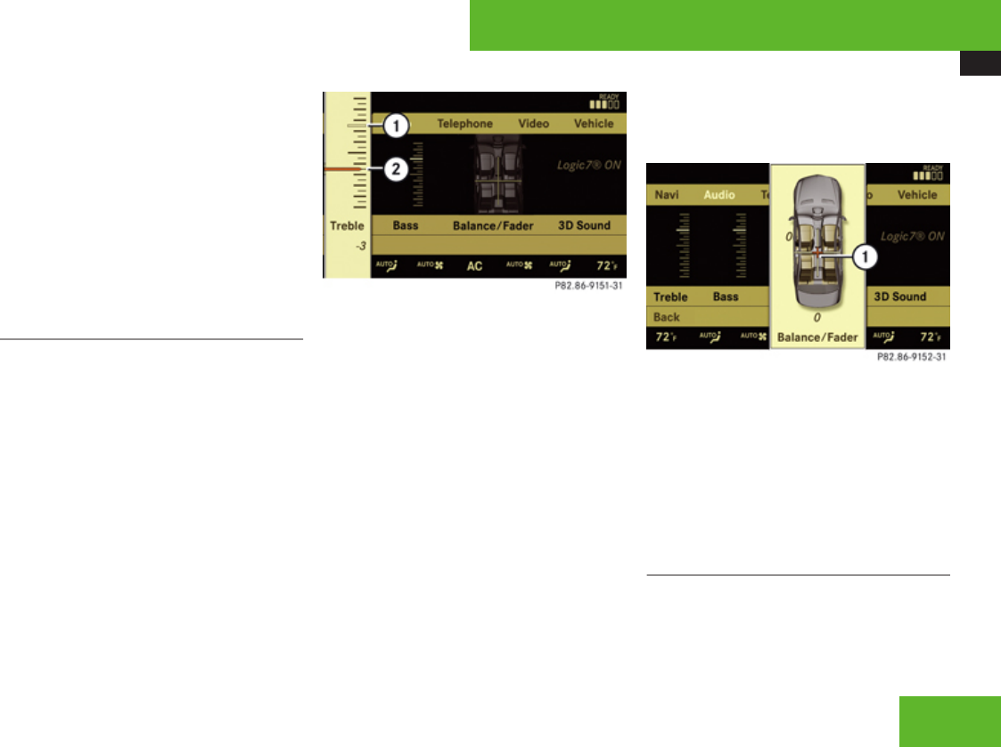
COMAND introduction
93
Adjusting volume for telephone calls
In hands-free mode, you can adjust the
volume of a telephone call while the call is
currently active.
During a telephone call:
XTurn thumbwheel ,.
or
XPress æ or ç on the multifunction
steering wheel.
Selecting sound settings
You can select different sound settings for
each individual audio source. The respective
sound menu can be found via the submenu
for which you wish to make settings.
Example: Audio £ Audio £ FM/AM
Radio £ Sound
Adjusting treble or bass
XSelect Sound £ Treble or Bass.
The setting last selected is indicated by an
outlined bar.
Adjusting treble and bass
1Setting last selected
2Current setting
XChanging setting: Slide qmr or rotate
ymz until desired treble or bass setting is
reached.
XExiting menu: Press n, L or slide
omp.
The setting is saved.
Adjusting balance or fader
Balance is used to determine whether the
sound focus should be shifted toward the
driver’s side or the passenger’s side.
Fader is used to determine whether the sound
focus should be shifted toward the front or
rear of the vehicle.
XSelect Sound £ Balance/Fader.
The setting last selected is indicated by an
outlined bar.
Adjusting balance and fader
1Current setting indicated by orange cross
hair symbol
XChanging setting: Slide qmr or omp until
desired balance/fader setting is reached.
XExiting menu: Press n or L.
The setting is saved.
Surround sound
With surround sound, you can choose
between LOGIC7® ON and LOGIC7® OFF.
Control systems
Z

COMAND introduction
94
Harman/kardon LOGIC7® surround sound is
available for the following operating modes:
RAudio DVD (MLP, DTS, PCM, and Dolby
Digital audio formats)
RVideo DVD (DTS, PCM, and Dolby Digital
audio formats)
RAudio CD
RMP3
RRadio (FM, AM, WB, Satellite)
RPCMCIA
RAUX
iSince some DVDs contain both stereo as
well as multi-channel audio formats, it may
be necessary to adapt the audio format
(Y page 209).
iThe LOGIC7® ON function of the harman/
kardon LOGIC7® surround sound system
makes it possible to play discrete 5.1 and
stereo recordings with optimal surround
sound for every passenger. Music on CDs
or audio DVDs with high-resolution
surround formats such as MLP, DTS or
Dolby Digital is played back optimally.
For an ideal sound experience on all seats,
LOGIC7® distributes 5.1 surround
information via the 13-channel system
architecture. The result is a sound as
intended by the sound engineers during the
original recording.
harman/kardon LOGIC7® converts all two-
channel stereo sound material into multi-
channel surround sound. With the help of
LOGIC7®, surround information stored
during the original recording are read out
and distributed through the 13 channels.
No effects are created during this process;
only that which was already there becomes
audible.
In addition, harman/kardon LOGIC7®
moves the perceived sound source away
from the individual loudspeakers, thus
generating a natural 360° sound
experience for every passenger.
iBy selecting LOGIC7® OFF, all compatible
formats as they are present on the medium
are played back. Due to the vehicle’s
spatial characteristics, an optimal sound
experience is not ensured on all seats.
Adjusting surround sound
With surround sound, you can choose
between LOGIC7® ON and LOGIC7® OFF.
XSelect Sound £ 3D Sound.
Adjusting surround sound
1Current setting
XSelecting a setting: Slide qmr or rotate
ymz.
XSaving setting: Press n.
The setting is saved and the menu is closed.
XExiting menu without saving changes:
Press L or slide omp.
iPlease note the following:
RFor an ideal sound experience at all
seats, the balance and fader should be
adjusted to the center of the passenger
Control systems

COMAND system settings
95
compartment with LOGIC7® switched
on.
RThe best sound results are achieved by
playing high-quality audio CDs and audio
DVDs.
RFor MP3 tracks, the bit rate should be at
least 128 kbit/s.
RSurround sound does not function for
mono-signal sources.
RIn the event of poor radio reception
quality, e. g. inside a tunnel, you should
switch off LOGIC7®, as a dynamic switch
from Stereo to Mono could occur,
resulting in temporary sound distortion.
RWith some stereo recordings, the
resulting sound may deviate from
conventional stereo playback.
Switching off/on the audio source
iWhen you insert an audio CD or audio
DVD, it automatically becomes the active
audio source.
XSwitching off: Select Audio £ Audio
£ Audio OFF.
The audio source is switched off; Audio
OFF appears in the display.
XSwitching on: Select Audio, then the
desired audio source.
or
XLoad CD/DVD (Y page 202) or a PCMCIA
card (Y page 204).
COMAND system settings
System settings menu overview
iThe components and operating principles
of COMAND can be found on (Y page 82).
Control systems
Z

COMAND system settings
96
Display
(Y page 96)
Time (Y page 96) Voice Control
(Y page 97)
Language
(Y page 98)
Favorite
(Y page 98)
Reset (Y page 99)
Display settings Time settings Voice Control
settings
Language settings Assign favorite
button
Reset COMAND to
factory settings
Display settings
Switching the display on or off
XSwitching off: Select Vehicle £
Display OFF.
XSwitching back on: Rotate ymz or slide
qmr.
Setting the display design
XSelect Vehicle £ System Settings
£ Display.
XSelect Day Mode, Night Mode or
Automatic.
iIn the Automatic setting, COMAND
analyzes the automatic vehicle light sensor
and switches between the display design
automatically.
Time settings
Setting the time
iThe correct time must be set for the
following navigation system functions to
operate correctly:
RRoute guidance on routes with time-
dependent traffic guidance
RCalculation of estimated arrival time
XSelect Vehicle £ System Settings
£ Time £ Time.
XSelecting hour or minute(s): Slide omp.
XSetting value: Rotate ymz or slide qmr.
XSaving setting: Press n.
iThe increment value for setting the
minutes depends on the situation. If GPS
reception is available, it is 30 minutes. If
GPS reception is not available, it is one
minute.
Setting the time zone and switching
between Daylight Saving Time and
standard time
iThe correct time zone and Daylight Saving
Time/standard time must be set for the
following navigation system functions to
operate correctly:
RRoute guidance on routes with time-
dependent traffic guidance
RCalculation of estimated arrival time
XSetting time zone: Select Vehicle £
System Settings £ Time £ Time
Zone.
The country list appears. The dot R in front
of a list entry indicates the current setting.
XSelect the country in which you are
currently driving.
A time zone list may also be displayed,
depending on the country selected.
XSelect desired time zone.
Control systems

COMAND system settings
97
Subsequent operation depends on:
Rwhether your navigation system has GPS
reception
Rwhich country you have previously set
You may either:
Rmanually switch between Daylight
Savings Time (Summer) and Standard
time (Winter) in a list
or
Rswitch automatic Daylight Saving Time to
standard time changeover (and vice versa)
on or off
XSwitching manually: Select Daylight
Savings Time (Summer) or Standard
time (Winter).
The dot R in front of a list entry indicates
the current setting.
XSwitching automatic changeover on or
off: Select Automatic Daylight
Savings Time.
You have switched the function on or off. A
checkmark appears when the function is
switched on.
iAvailability of the automatic daylight
saving time feature depends on the country
selected.
XSaving setting and exit the menu: Slide
omp.
iIf you have switched off the automatic
changeover function, you must change
Daylight Saving Time to standard time and
vice versa yourself.
Setting the date
XSelect Vehicle £ System Settings
£ Time £ Date.
XSelecting month, day or year: Slide
omp.
XSetting value: Rotate ymz or slide qmr.
XSaving setting: Press n.
Setting the time/date format
XSelect Vehicle £ System Settings
£ Time £ Format.
The format list appears. The dots R in
front of the list entries indicate the current
setting.
XChanging format setting: Select desired
format.
XSaving setting and exit the menu: Slide
omp.
Voice Control settings
Switching help window on or off
XSelect Vehicle £ System Settings
£ Voice Control.
XSelect Help Window.
You can switch the help window on or off.
A checkmark appears when the help
window is switched on.
Individualization
Using individualization, you can fine-tune
Voice Control to your own voice and thus
improve voice recognition. The ability of the
system to recognize the commands of other
users does not deteriorate as a result.
Individualization consists of two parts. You
train the system to recognize digits in the first
part and specific commands in the second
part.
Starting new individualization
iIt is only possible to start individualization
with the vehicle stationary. After starting
the session, the system will guide you
through the individualization by means of
acoustic instructions.
Control systems
Z

COMAND system settings
98
XSelect Vehicle £ System Settings
£ Voice Control £ Start new
individualization.
A prompt appears asking whether you
would like further information.
XSelect Yes or No.
If you select No, the first part of
individualization begins.
If you select Yes, an information display will
be shown with audio instruction.
XClosing display: Select OK.
The first part of individualization begins.
At the end of the first part, you will see a
prompt asking whether you want to begin
the second part.
XSelect Yes or No.
If you select No, individualization will be
canceled. The data from the first part is
saved automatically.
If you select Yes, the second part begins.
Individualization is completed at the end of
the second part. You will see a message to
this effect. The data from the second part is
saved automatically.
Canceling during the first or second part
of individualization
XSelect Cancel.
A prompt appears asking whether you
really do want to cancel.
XSelect Yes or No.
If you select Yes, individualization will be
canceled. The data from the part at which
you exited is not saved.
If you select No, the part at which you
stopped begins again.
Deleting existing individualization data
XSelect Vehicle £ System Settings
£ Voice Control £ Delete
individualization.
A prompt appears asking whether you
really do want to delete.
XSelect Yes or No.
The individualization data will either be
deleted or not, depending on your
selection.
Setting the system language
XSelect Vehicle £ System Settings
£ Language.
The language list appears. A dot R
indicates the current setting.
XChanging setting: Select desired
language.
The language is set.
Assigning the favorite button
1Favorite button
You can assign the following predefined
functions to the favorite button *:
RRear Window Sunshade (Y page 421)
Control systems

COMAND navigation (introduction)
99
You can use the favorite button to extend
or retract the rear window sunshade. This
is the default setting.
RDisplay OFF (Y page 96)
You can use the favorite button to switch
the COMAND display on or off.
RRepeat Navigation Command
(Y page 144)
You can use the favorite button to recall the
last announcement issued by the
navigation system.
XSelect Vehicle £ System Settings
£ Favorite.
The list of predefined functions appears.
The dot R in front of the list entry indicates
the current setting.
XChanging setting: Rotate ymz and select
desired function.
XSaving setting and exit the menu:
Press n.
Reset
iYou can reset COMAND back to its
factory settings.
In this case, all personal data (e.g. address
book entries, entries in the destination
memory and the list of last destinations of
the navigation system), among other
things, are deleted.
XSelect Vehicle £ System Settings
£ Reset.
A prompt appears asking whether you
really want to reset.
XSelect Yes or No.
If you select Yes another prompt will
appear asking whether you really want to
reset.
XSelect Yes or No.
If you select Yes, COMAND will be reset
and restarted.
COMAND navigation (introduction)
Safety notes
GWarning!
For safety reasons, only enter a destination
when the vehicle is stationary. When the
vehicle is in motion, a passenger should
enter the destination. Study manual and
select route before driving.
Bear in mind that at a speed of just 30 mph
(approximately 50 km/h), your vehicle is
covering a distance of 44 feet
(approximately 14 m) every second.
COMAND calculates the route to the
destination without taking account of the
following, for example:
RTraffic lights
RStop and right-of-way signs
RParking or stopping prohibited areas
RLane merging
ROther road and traffic rules and
regulations
RNarrow bridges
COMAND may give incorrect navigation
commands if the data in the digital map
does not correspond with the actual road/
Control systems
Z

COMAND navigation (introduction)
100
traffic situation. DVD maps do not cover all
areas nor all routes within an area. For
example, if the traffic routing has been
changed or the direction of a one-way road
has been reversed.
For this reason, you must always observe
applicable road and traffic rules and
regulations during your journey. Road and
traffic rules and regulations always have
priority over the navigation commands
generated by the system.
GWarning!
Navigation announcements are intended to
direct you while driving without diverting
your attention from the road and driving.
Please always use this feature instead of
consulting the map display for directions.
Consulting the symbols or map display for
directions may cause you to divert your
attention from driving and increase your
risk of an accident.
Map software
The digital maps generated by the map
software become outdated in the same way
as conventional road maps. Optimum route
guidance can only be provided by the
navigation system in conjunction with the
most up-to-date map software. Information
about new map software versions can be
obtained from an authorized Mercedes-Benz
Center.
Updating the map software
You can update the map software yourself
using a DVD.
Notes about handling DVDs
ROnly hold discs by the edge.
RHandle discs carefully to prevent read
problems.
RAvoid getting scratches, fingerprints and
dust on discs.
RUse a commercially-available cleaning
cloth to clean discs. Do not wipe them with
a circular motion, but only in straight lines
from the center outwards.
RPlace discs back in their boxes after use.
RProtect discs from heat and direct sunlight.
Updating process
The updating process has the following
phases:
RLoading a DVD into the DVD changer
(Y page 101)
RUpdating process (Y page 102)
iThe updating process can take between
10 and 60 minutes, depending on the size
of the map software. If the radio was
switched on before you started the
updating process, you can still adjust the
volume. You can also use COMAND to
operate the automatic air conditioning and
to cancel the process. Other functions are
not operational. If possible, carry out the
update when the vehicle is stationary.
iIf you carry out the update with the engine
switched off and the vehicle battery has
insufficient power, COMAND may
automatically switch off during the process
in order to protect the battery. If this
occurs, restart the update with the engine
running period. Similarly, if the SmartKey
Control systems
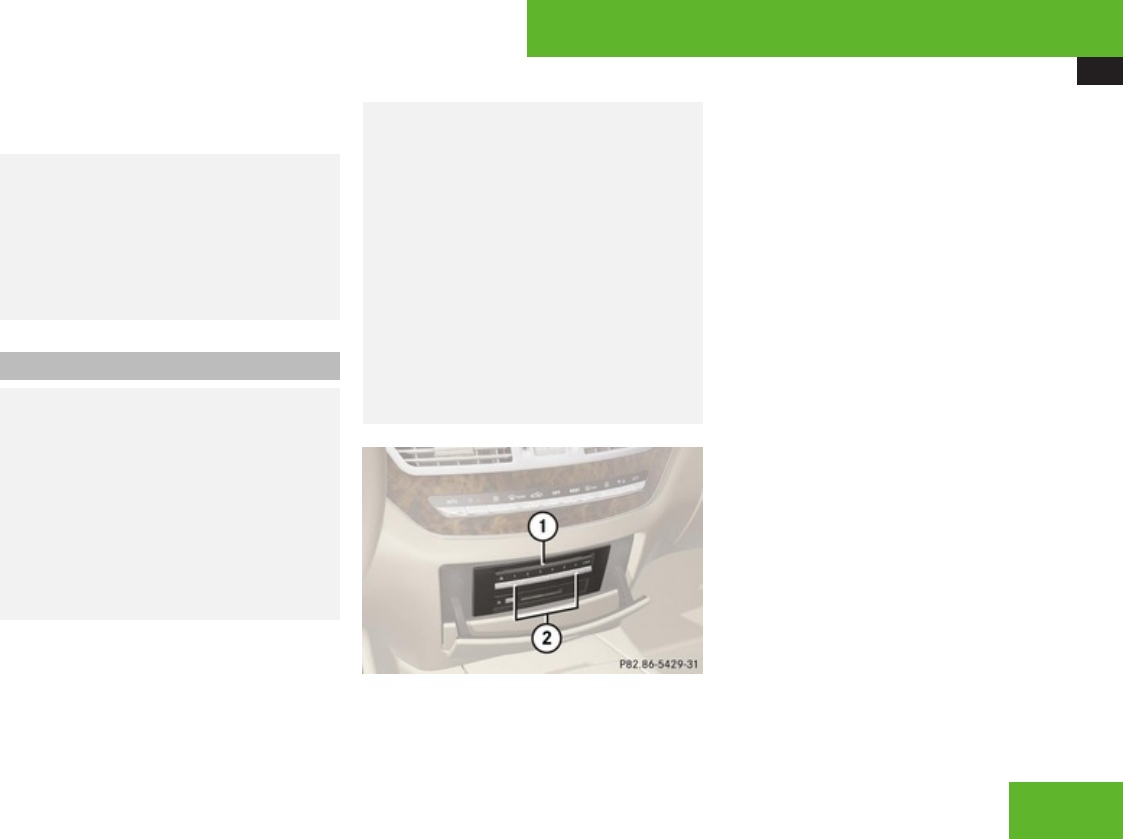
COMAND navigation (introduction)
101
position is unintentionally switched to 0,
restart the update.
GWarning!
Never leave the engine running in an
enclosed space. Inhalation of exhaust gas
is hazardous to your health. All exhaust gas
contains carbon monoxide (CO), and
inhaling it can cause unconsciousness and
possible death.
Loading a DVD into the DVD changer
GWarning!
COMAND is classified as a Class 1 laser
product. You must not open the casing.
There is a risk of exposure to invisible laser
radiation if you open the casing, or if the
casing is faulty or damaged.
COMAND does not contain any parts that
you are able to maintain yourself. For safety
reasons, all maintenance work must be
carried out by qualified technicians.
GWarning!
Only carry out the following when the
vehicle is stationary:
RInserting a disc
REjecting a disc
There is a risk of accident by being
distracted from road and traffic conditions
if you load a CD/DVD while the vehicle is
in motion.
Bear in mind that at a speed of just 30 mph
(approximately 50 km/h), your vehicle is
covering a distance of 44 feet
(approximately 14 m) every second.
1Disc slot
2Magazine tray buttons 1 – 6
iEach magazine tray button 2 indicates
the status of the corresponding magazine
tray by means of an LED.
RLED off = magazine tray is empty
RLED constantly lit = magazine tray is
loaded
RLED flashes = CD/DVD changer
requesting disc to be loaded
XSwitch on COMAND (Y page 83).
XPress one of magazine tray buttons 2.
If a disc is loaded, it will be ejected.
XTake disc out of slot 1.
XWait until LED for magazine button 2
which you pressed flashes quickly.
XSlide DVD into slot 1 with printed side
facing upwards.
COMAND loads the DVD.
Control systems
Z

COMAND navigation (introduction)
102
Updating
After you have loaded the DVD, you will see a
message to the effect that the disc does not
contain a recognizable audio format.
XConfirming message: Press n.
COMAND checks whether the map
software on the DVD is compatible with the
vehicle’s navigation system and whether it
is compatible with the current system
software.
Map software is compatible with the
navigation system and the current
system software
COMAND now checks whether the map data
on the DVD is already installed.
Map data is not yet installed
You will see a comparison of the version
statuses in the display and a prompt will
appear asking whether you want to continue
with the update.
XSelect Yes or No.
If you select No, COMAND automatically
ejects the DVD and the map data is not
updated.
Take DVD out of the slot.
If you select Yes, the map data is updated.
Map data is already installed
You will see a message that the map data is
already installed and a prompt will appear
asking you whether you want to continue with
the update.
XSelect Yes or No.
If you select No, COMAND automatically
ejects the DVD and the map data is not
updated.
Take DVD out of slot.
If you select Yes, the existing map data is
saved again.
Updating the map data
While the update is running, you will see a
message to this effect and a progress bar. The
progress bars fills up from left to right during
the update.
1Progress bar
You can either cancel the update or allow it
to run to the end without canceling.
XCanceling an update on the DVD
changer: Press corresponding magazine
tray button 2 (Y page 101).
The DVD will be ejected in both cases.
XTake DVD out of slot.
iIf the update is canceled, the navigation
system remains fully operational with the
previous map data. You can restart the
update at a later date. It will then continue
from the point where it was canceled.
Control systems

COMAND navigation (introduction)
103
XTo allow the update to run to the end
without canceling: Take no further action.
If the update is successfully completed, you
will see a message to this effect.
XConfirming message: Press n.
COMAND ejects the DVD.
XTake DVD out of slot.
The update is complete.
If the update is not successfully completed,
you will see a message that the map update
is not possible.
XConfirming message: Press n.
COMAND ejects the DVD.
XTake DVD out of slot.
iThe navigation system remains fully
operational with the previous map data.
The update may not be successfully
completed for the following reasons:
RDVD dirty or scratched
XClean DVD.
See the “Notes about handling DVDs”
section (Y page 100).
XRestart update.
ROverheating due to excessive
temperatures in the vehicle interior
XWait until vehicle interior has cooled
down.
XRestart update.
RThe storage medium (hard disk) integrated
in COMAND is defective.
XContact an authorized Mercedes-Benz
Center.
Map software is not compatible with
the navigation system
You will see a message that the update is not
possible.
XConfirming message: Press n.
COMAND ejects the DVD.
XTake DVD out of slot.
XLoad a DVD which is compatible with the
vehicle’s navigation system.
Map software is not compatible with
the current system software
You will see a message that the system
software and the map software are not
compatible.
XConfirming message: Press n.
COMAND ejects the DVD.
XTake DVD out of slot.
XHave the system software updated at an
authorized Mercedes-Benz Center.
iThe map software cannot be updated until
the system software has been updated.
General notes
Operational readiness of the navigation
system following a system software
update by an authorized Mercedes-Benz
Center
After a system software update by an
authorized Mercedes-Benz Center, the
installed map software may no longer be
compatible. If this is the case, the navigation
system will not be operational.
You will know if this is the case, when the
following message will appear when you
switch to navigation mode: The system
software has been updated. The map
software must be updated now. Please
insert the DVD with the map software.
XUpdating map software: Proceed as
described in the “Updating the map
software” section (Y page 100). Use map
Control systems
Z

COMAND navigation (introduction)
104
software which is compatible with the
system software.
iPlease note that the update must be
allowed to run to the end in this case. If you
interrupt it, the navigation system will
continue to be non-operational.
Initial use or use following a system
software update
In both these cases, the navigation system
must determine the position of the vehicle.
You may have to drive for a while before
precise route guidance is possible.
GPS reception
Correct functioning of the navigation system
depends on GPS reception, among other
things. In certain situations, GPS reception
may be impaired, there may be interference
or there may be no reception at all, e. g. in
tunnels, in multistory parking garage or due
to snow on the GPS antenna. If there is snow
on the GPS antenna, you should remove it.
The GPS antenna is at the back of the vehicle
roof.
The roof cargo container may also impair
mobile phone reception and GPS coverage.
Route guidance after vehicle
transportation
COMAND has to redetermine the position of
the vehicle if the vehicle has been transported
(e. g. by ferry, by train or after towing).
Positioning takes place automatically even
when COMAND is switched off. The duration
varies from one case to another.
Route guidance may be restricted as follows
during vehicle positioning:
RNavigation announcements, route
guidance displays and displayed street
names are not consistent with the actual
location of the vehicle.
RCOMAND does not generate navigation
announcements.
RInstead of the route guidance displays, you
see the Off Road display and a direction
arrow. The direction arrow shows the
compass heading to the destination.
When positioning is complete, route guidance
is once again possible using navigation
announcements and route guidance displays.
Interrupting the journey during route
guidance
The following applies if you interrupt the
journey during route guidance and continue
the journey later:
RCOMAND resumes route guidance
automatically if you continue the journey
within 2 hours.
RRoute guidance is canceled if you continue
the journey after more than 2 hours. It will
be necessary to resume the canceled route
guidance manually (Y page 145).
iThe journey is interrupted if you park the
vehicle and switch off COMAND. The
journey is continued when you switch
COMAND back on and start driving on.
Hard disk errors
COMAND has an integrated hard disk on
which the map software is saved.
If an area of the hard disk has an error,
COMAND can no longer access the map data
in this area, for example, when calculating a
route.
The message Navigation Unavailable.
Please refer to the operating
instructions. appears.
Control systems

COMAND navigation (introduction)
105
XDeleting message: Switch COMAND off
and back on.
iIf you switch the navigation system off/
on, it will be operational again until it has
to access the faulty area of the hard disk
again. The message will then appear again.
Consult an authorized Mercedes-Benz
Center.
Units of measurement
The units of measurement in navigation mode
are identical to those set in the instrument
cluster (Y page 253).
Input restrictions
The input restrictions are imposed starting at
a particular vehicle speed. The restrictions
are canceled as soon as the speed drops
below a certain value.
When the restriction is active, certain
operations or entries are not possible.
You will notice this by the fact that some
menu items cannot be selected or certain
operations will not be possible.
Navigation system menu overview
iThe components and operating principles
of COMAND can be found on (Y page 82).
Control systems
Z
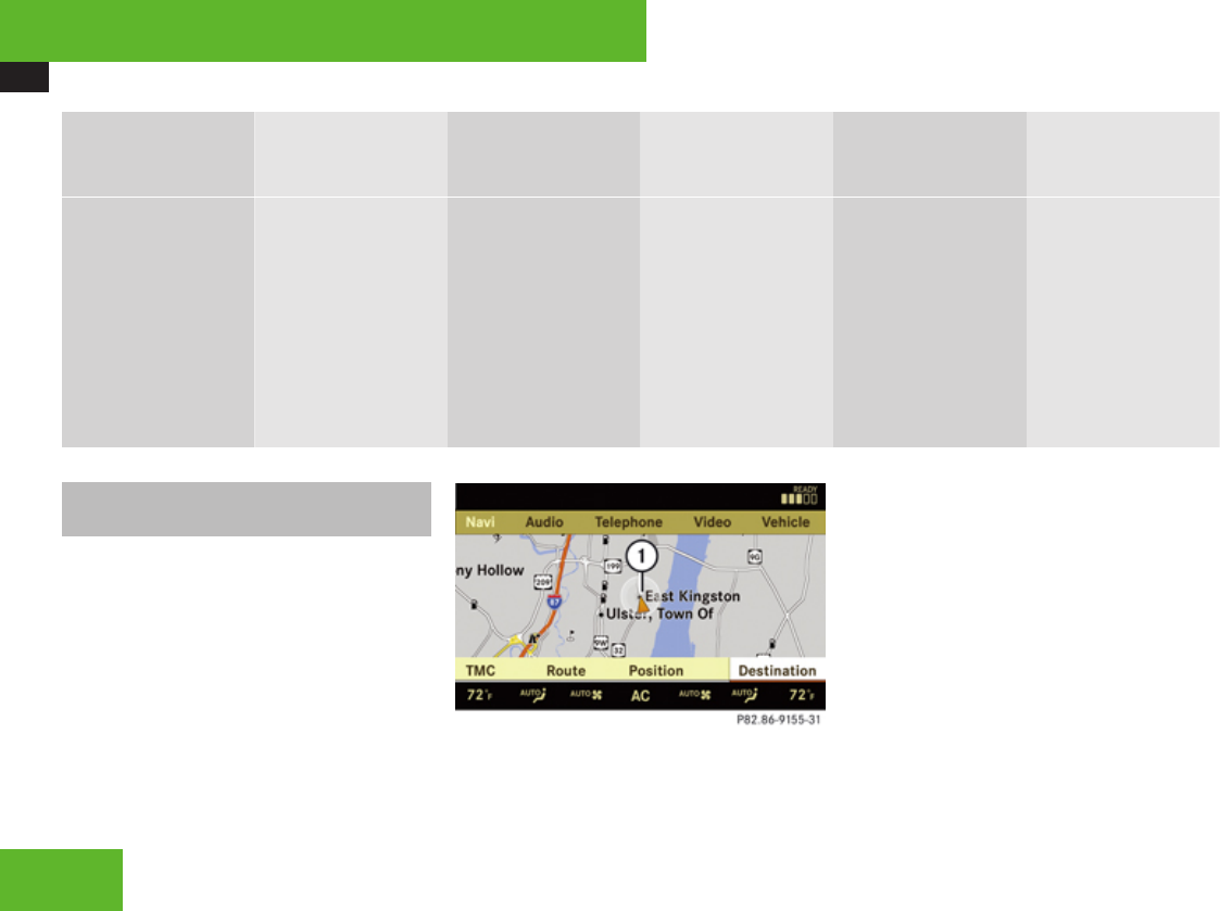
COMAND navigation (introduction)
106
Info
(only with route
guidance active)
Traffic (TMC) Route
(only with route
guidance active)
Position RPT
(only with route
guidance active)
Destination
Information about
the active route
guidance
Calling up real-time
traffic messages
RCalling up route
info
RCalling up route
browser
RCalling up the
detour function
RCalling up the save
position memory
function
RCentering the map
on the vehicle’s
position
RCentering the map
on the destination
position
Repeating the
current navigation
announcement
Selecting:
Ra destination
Rstopover
Rsave destination
Rcancel route
guidance
Calling up the map display and
switching to navigation mode
XIn the main function line, select Navi.
or
XPress the N shortcut button once or
twice.
iThe number of times you have to press
the N shortcut button depends on the
operating mode currently selected.
Both of these will call up the map display. You
will see the map with the menu system either
shown or hidden.
Example illustration: Map with route guidance
inactive and with the menu system shown
1Current vehicle position
Control systems
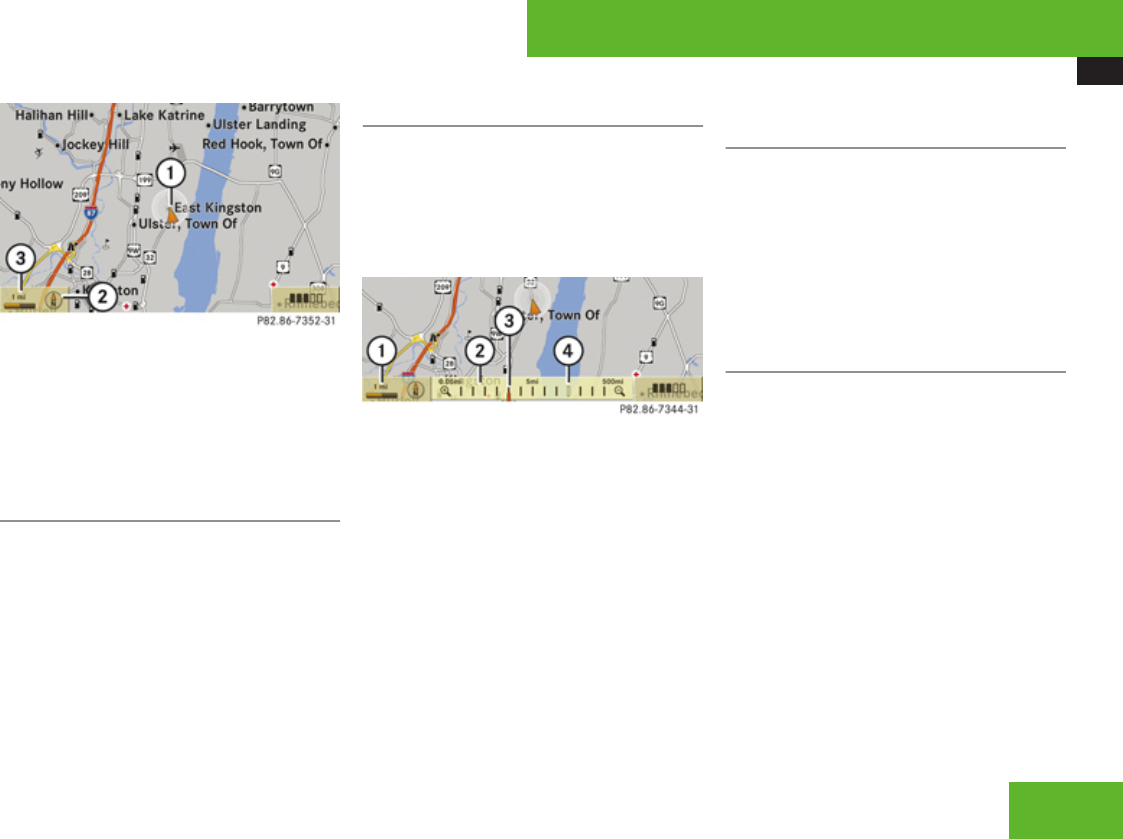
COMAND navigation (introduction)
107
Example illustration: Map with route guidance
inactive and with the menu system hidden (full
screen mode)
1Current vehicle position
2Set map orientation (Y page 109)
3Map scale selected (Y page 107)
Hiding or showing the menu system
XHiding: Slide qm.
The Full Screen menu item appears in
the main area of the display; it is
automatically selected.
XPress n.
The menu system is hidden. The map can
be seen in the full screen.
XShowing: Press n in the full-screen map
display.
Adjusting the map scale
iIt is only possible to adjust the map scale
with the menu system hidden (full-screen
map display).
XRotate ymz until the desired map scale is
set.
1Currently set map scale as number
2Scale
3Currently set map scale as a needle on the
scale
4Previously set value before calling up the
scale
As soon as you rotate ymz, scale 2 appears.
Rotating clockwise zooms in, rotating
counterclockwise zooms out.
Saving current vehicle position as
destination in last destinations list
XShowing menu system, if necessary:
Press n.
XSaving: Select Position £ Save
Position.
COMAND saves the current vehicle
position as a destination in the last
destinations (Y page 155).
Moving the map
iIt is only possible to move the map with
the menu system hidden.
XSlide qmr, omp or wmx.
A cross hair appears on the map.
Control systems
Z
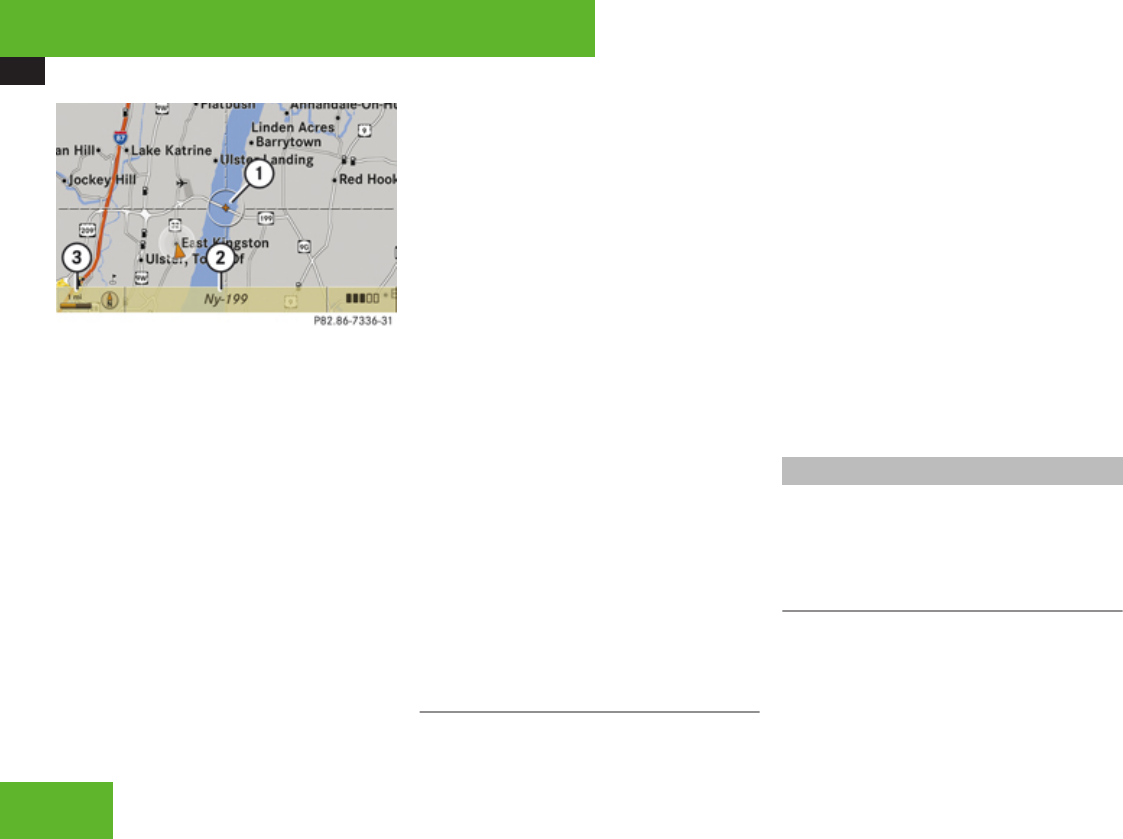
COMAND navigation (introduction)
108
1Cross hair
2Details of the cross hair position
3Map scale
iDisplay 2 may be the name of a road, for
example, provided the digital map contains
the necessary data.
If no data is available, display 2 shows:
Rthe coordinates of the cross hair if the
geocoordinate display is switched on
(Y page 110) and the GPS signal is
strong enough
Rno display if the geocoordinate display is
switched off (Y page 110)
Adjusting the map scale
XRotate ymz.
Rotating clockwise zooms in, rotating
counterclockwise zooms out.
Saving cross hair position as destination
in last destinations list
XShowing menu system, if necessary:
Press n.
XSaving: Select Position £ Save
Position.
COMAND saves the cross hair position as
a destination in the last destinations list
(Y page 155).
Hiding the cross hair
XPress back button L in the center
console (Y page 90).
The cross hair disappears and the map is
centered on the vehicle position.
or
XSet the map to the vehicle or destination
position, see the explanation below.
Centering the map on the vehicle or
destination position
iIf you have moved the map, you can use
this function to rapidly return the map to
the position of the vehicle or destination. It
is only possible to center the map on the
destination position when route guidance
is active.
XCentering on the vehicle’s position:
Select Navi £ Position £ Vehicle
Position Map.
or
XPress back button L when the cross
hair is displayed.
XCentering on the destination: Select
Navi £ Position £ Destination
Position Map.
Basic settings
iYou can make the following settings
regardless of whether route guidance is
active or inactive.
Map perspective
COMAND can display the map from a bird’s
eye view or in the normal map view.
Control systems
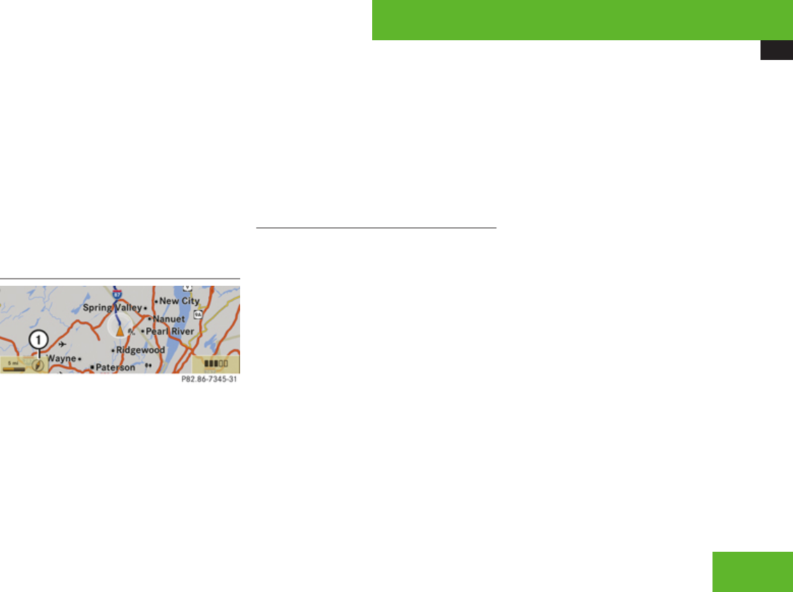
COMAND navigation (introduction)
109
XSelect map perspective: Select Navi
£ Navi £ Map Display.
The map display list appears. A dot R
indicates the current setting.
XSelect Bird’s-eye view.
The bird’s eye view is switched on or off,
depending on the previous status.
iIf you scroll the map in the bird’s eye view,
COMAND switches back to the normal map
view.
Map orientation
1Current map orientation
The following may be displayed:
R8 = Heading Up (the map is displayed so
that the direction of travel is always up; the
orange point of the icon points north)
R9 = North Up (the map view is displayed
so that north is always up)
XSetting map orientation: Select Navi
£ Navi £ Map Display.
The map display list appears. A dot R
indicates the current setting.
XSelect North Up or Heading Up.
XExiting menu: Slide omp.
The map orientation changes accordingly.
Setting POI symbols
You can set which points of interest (POIs)
should be displayed as symbols in the map.
POIs are garages, hotels, movie theaters or
restaurants, for example.
iDepending on the map scale on the map,
POI symbols may not be visible on the map
although their display is activated. In
addition, POI symbols may be covered by
the map’s labels.
The following settings are possible:
RStandard symbols (symbol determined
by the factory settings)
RPersonal symbols (you can determine
the symbols yourself)
RNo symbols
XAdjusting: Select Navi £ Navi £ Map
Display.
The map display list appears. A dot R
indicates the current setting.
XSelect Standard symbols, Personal
symbols or No symbols.
If you select Personal symbols, the list of
POIs appears.
XSwitching POI symbol display on or
off: Select the desired POI.
The corresponding symbol displays are
switched on or off, depending on the
previous status. A checkmark indicates
which status is active. You can switch on
the symbol displays for more than one POI.
iThe list shows all symbols that are
contained in the digital map across all
states (USA) and/or provinces (Canada).
Not all POIs in all states (USA) or in all
provinces (Canada) are available, however.
Certain POI symbols may not be displayed
on the map, even if the symbol display is
switched on.
XExiting menu: Slide omp or press back
button L in the center console
(Y page 90).
Control systems
Z
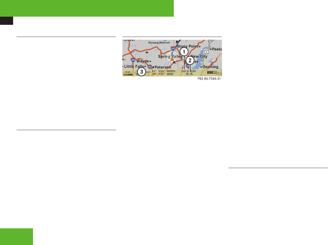
COMAND navigation (introduction)
110
Arrival time and distance
You can set whether the estimated arrival
time and the distance to the destination
should be displayed in the map.
XDisplaying: Select Navi £ Navi £ Map
Display.
The map display list appears. A dot R
indicates the current setting.
XSelect Arrival Time/Distance.
Depending on the previous status the
display showing the arrival time and
distance is switched on or off.
Current street
You can set whether the current street you
are driving on should be displayed in the map.
XDisplaying: Select Navi £ Navi £ Map
Display.
The map display list appears. A dot R
indicates the current setting.
XSelect Current Street.
Depending on the previous status the
display showing the current street is
switched on or off.
Geocoordinate display
Example illustration: Map with geocoordinate
display switched on
1Current height above sea level
2Number of GPS satellites from which
signals for positioning can be received
3Coordinate display
iThere must be sufficient GPS reception
for displays 1, 2 and 3 to be shown.
Height display 1 is an approximation
because the navigation system uses the
GPS signals for the calculation.
Display options with geocoordinate
display switched on
If the cross hair is displayed on the map view
(map was moved manually), only display 3
is visible.
It shows either the coordinates of the cross
hair or other data on the cross hair position,
e. g. a street name. The digital map must
contain relevant data in order for this other
data to be displayed.
iIf there is no cross hair on the map view,
displays 1, 2 and 3 are visible. Display
3 shows the coordinates of the current
vehicle position.
Switching the geocoordinate display on or
off
XSelect Navi £ Navi £ Map Display.
The map display list appears.
XSelect Coordinates.
The geocoordinate display is switched on
or off, depending on the previous status. A
checkmark indicates which status is active.
XExiting menu: Slide omp or press back
button L in the center console
(Y page 90).
Setting route type
You can set the following route types:
RFast Route: COMAND calculates a route
with the shortest possible (minimized)
driving time.
RShort Route: COMAND calculates a route
with the shortest possible (minimized)
Control systems

COMAND navigation system (entering a destination)
111
distance taking distance and driving time
into account.
XSelect Navi £ Navi £ Mode.
The mode list appears. A square ÿ
indicates the current setting.
XSelect route type: Fast Route or Short
Route.
XExit menu: Slide omp or press back
button L in the center console
(Y page 90).
iIf you change the route type setting during
active route guidance, COMAND calculates
a new route. If you change the setting when
route guidance is inactive, COMAND uses
the new setting for the next route guidance.
Setting route mode
iThis function allows you to set the
following options for route guidance:
RMinimize Highways
RMinimize Toll Roads
RMinimize Tunnels
RMinimize Ferries/Motorail
XSelect Navi £ Navi £ Mode.
The mode list appears.
XSwitching mode on or off: Select desired
modes.
Depending on the previous status, the
mode is switched on or off. A checkmark
indicates that the mode is switched on. It
is possible to switch on more than one
mode.
XExiting menu: Slide omp or press back
button L in the center console
(Y page 90).
COMAND will verify whether it can
incorporate the modes if you select them
with route guidance active.
If it can, COMAND calculates a new route
while incorporating the modes selected.
If it cannot, you will see and hear a
corresponding message.
XSelect OK.
COMAND calculates a new route. Only
those modes which can be incorporated
are used.
COMAND navigation system (entering
a destination)
Introduction
GWarning!
For safety reasons, only enter a new
destination when the vehicle is stationary.
iIt is possible to enter a destination
regardless of whether route guidance is
active or inactive.
The following destination entry options are
available:
REntering a destination by address
REntering a destination from the destination
memory
REntering a destination from the list of last
destinations
REntering a destination from the map
REntering a stopover
REntering a POI
Control systems
Z
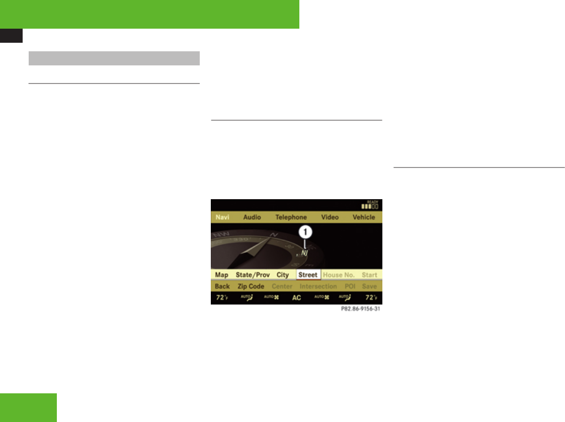
COMAND navigation system (entering a destination)
112
Entering a destination by the address
Introduction
iIt is not possible to enter an address when
the vehicle has exceeded a certain speed.
As soon as the vehicle speed drops below
a certain value, the function is available
again.
iIf Russian or Chinese is set as the system
language, the address must be entered
using Latin letters. Setting the system
language (Y page 98).
To enter an address you may proceed as
follows:
REnter state (USA) or province (Canada),
street and city
REnter state (USA) or province (Canada), city
and street
REnter state (USA) or province (Canada), city
and center
REnter state (USA) or province (Canada), zip
code and center
REnter state (USA) or province (Canada), zip
code and street
iAs additional information to the street
entry, you can enter either a house number
or an intersection.
A zip code entry replaces the city entry.
Calling up the address input menu
XSelect Navi £ Destination £
Address Entry.
The address input menu appears. It shows
a state (USA) or a province (Canada). Which
state or province is shown depends on the
vehicle’s location.
1State (USA) or province (Canada)
Menu items in the address input menu
Some menu items will not or not yet be
available, depending on the sequence in
which you enter the address and the data
version.
Example: If you have not made any entries,
menu items House No., Center,
Intersection, POI, Start and Save will not
yet be available. And the Zip Code menu item
will not be available if the digital map does not
contain any zip codes.
Entering a state (USA)
iYou can only enter those states which are
saved on the digital map.
XIn the address input menu, select State/
Prov £ States (U.S.).
A list of states appears with input
characters; the input characters are
automatically activated.
Control systems
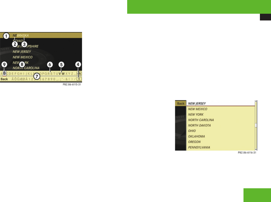
COMAND navigation system (entering a destination)
113
List of states with input characters
1Top list entry based on the input data up
to that point
2Characters entered by the user
3Characters automatically added by the
system
4Clear last character entry
5Currently selectable characters
6Currently non-selectable characters
7Input characters
8List of states
9Currently selected characters
iIn the list of input characters 7, you can
only select currently selectable characters.
Which characters are included depends on
the sequence in which you have entered
your destination and the data version of the
digital map.
While the numbers are being selected as
described below, the top list entry 1 always
shows the state which best corresponds to
the input data as it has been entered up to
that point.
At the same time, COMAND automatically
supplements characters 2 entered by the
user with other likely input characters 3.
XSelecting characters: Slide omp or
rotate ymz.
XConfirming character selection:
Press n.
XDeleting individual characters:
Select ) in the bottom line and press n.
XDeleting an entire entry: Select ) in the
bottom line and press n until the entire
entry is deleted.
XCanceling an entry: Select Back in the
bottom line and press n.
or
XPress back button L in the center
console (Y page 90).
As soon as COMAND can clearly attribute the
characters entered to a state, the input
characters 7 disappear automatically. You
see the list of states without the input
characters. Here you can confirm the current
entry or make another selection.
During character entry, you can also manually
switch to the list of states without input
characters at any time.
XSwitching manually to list of states
without input characters: Slide qm.
or
XSelect d in the second line from the
bottom and press n.
List of states without input characters
Control systems
Z

COMAND navigation system (entering a destination)
114
XSelecting a state: Slide qmr or rotate
ymz.
XCanceling selection: Select Back by
sliding om and press n.
or
XPress back button L in the center
console (Y page 90).
XConfirming selection: Press n.
The address input menu appears again. It
shows the abbreviation for the selected
state.
The following menu items are now available:
RMap: Entering a destination from the map
(Y page 130)
RState/Prov: Reenter state (USA) or
province (Canada)
RCity: Entering a city (Y page 116)
RStreet: Entering a street (Y page 119)
RZip Code: Entering the zip code
(Y page 115)
iIt is not possible to enter zip codes if the
digital map does not contain any zip codes
for the selected state.
XContinuing destination entry: Select one
of the menu items mentioned above.
Entering a province (Canada)
XIn the address input menu, select State/
Prov £ Provinces (Canada).
A list of provinces appears.
XSelect desired province.
The address input menu appears again. It
shows the abbreviation for the selected
province.
The following menu items are now available:
RMap: Entering a destination from the map
(Y page 130)
RState/Prov: Reenter state (USA) or
province (Canada)
RCity: Entering a city (Y page 116)
RStreet: Entering a street (Y page 119)
RZip Code: Entering the zip code
(Y page 115)
iIt is not possible to enter a zip code if the
digital map does not contain any zip codes
for the selected province (Canada).
XContinuing destination entry: Select one
of the menu items mentioned above.
Quick access to most recently entered
states (USA) or provinces (CDN)
XIn the address input menu, select State/
Prov £ Last States/Provinces.
The list of most recently entered states
(USA) or provinces (Canada) appears. The
last entry is at the top of the list.
XSelect desired state (USA) or desired
province (Canada).
The address input menu appears again. It
shows the abbreviation for the selected
state (USA) or province (Canada).
The following menu items are now available:
RMap: Entering a destination from the map
(Y page 130)
RState/Prov: Reenter state (USA) or
province (Canada)
RCity: Entering a city (Y page 116)
RStreet: Entering a street (Y page 119)
RZip Code: Entering the zip code
(Y page 115)
iIt is not possible to enter a zip code if the
digital map does not contain any zip codes
Control systems
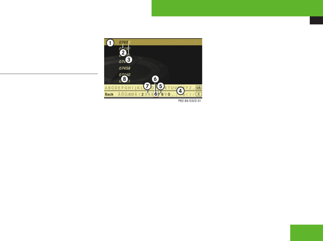
COMAND navigation system (entering a destination)
115
for the selected state (USA) or province
(Canada).
XContinuing destination entry: Select one
of the menu items mentioned above.
Entering the zip code
iIt is not possible to enter a zip code if you
have already entered other address data
aside from the state (USA) or province
(Canada).
You can only enter those zip codes which
are saved on the digital map.
The available zip codes depend on the state
(USA) or province (Canada) most recently
entered.
XIn the address input menu, select Zip
Code. A list of zip codes appears with input
characters; the input characters 4 are
automatically activated.
List of zip codes with input characters
1Top list entry based on the input data up
to that point
2Numbers entered by the user
3Numbers automatically added by the
system
4Input characters
5Currently selectable numbers
6Currently selected numbers
7Currently non-selectable numbers
8List of zip codes
iIn the list of input characters 4, you can
only select numbers which can be currently
entered. Which characters are included
depends on the sequence in which you
have entered your destination and the data
version of the digital map.
While the numbers are being selected as
described below, the top list entry 1 always
shows the zip code which best corresponds
to the input data as it has been entered up to
that point.
At the same time, COMAND automatically
supplements numbers 2 entered by the user
with other likely numbers 3.
XSelecting numbers: Slide omp or rotate
ymz.
or
XEnter numbers with the telephone keypad
using the R - 9 buttons
(Y page 85).
XConfirming number selection: Press n.
XDeleting individual numbers: Select )
in the bottom line and press n.
XDeleting an entire entry: Select ) in the
bottom line and press n until the entire
entry is deleted.
XCanceling an entry: Select Back in the
bottom line and press n.
or
XPress back button L in the center
console (Y page 90).
As soon as COMAND can clearly attribute the
numbers entered to a zip code, input
Control systems
Z
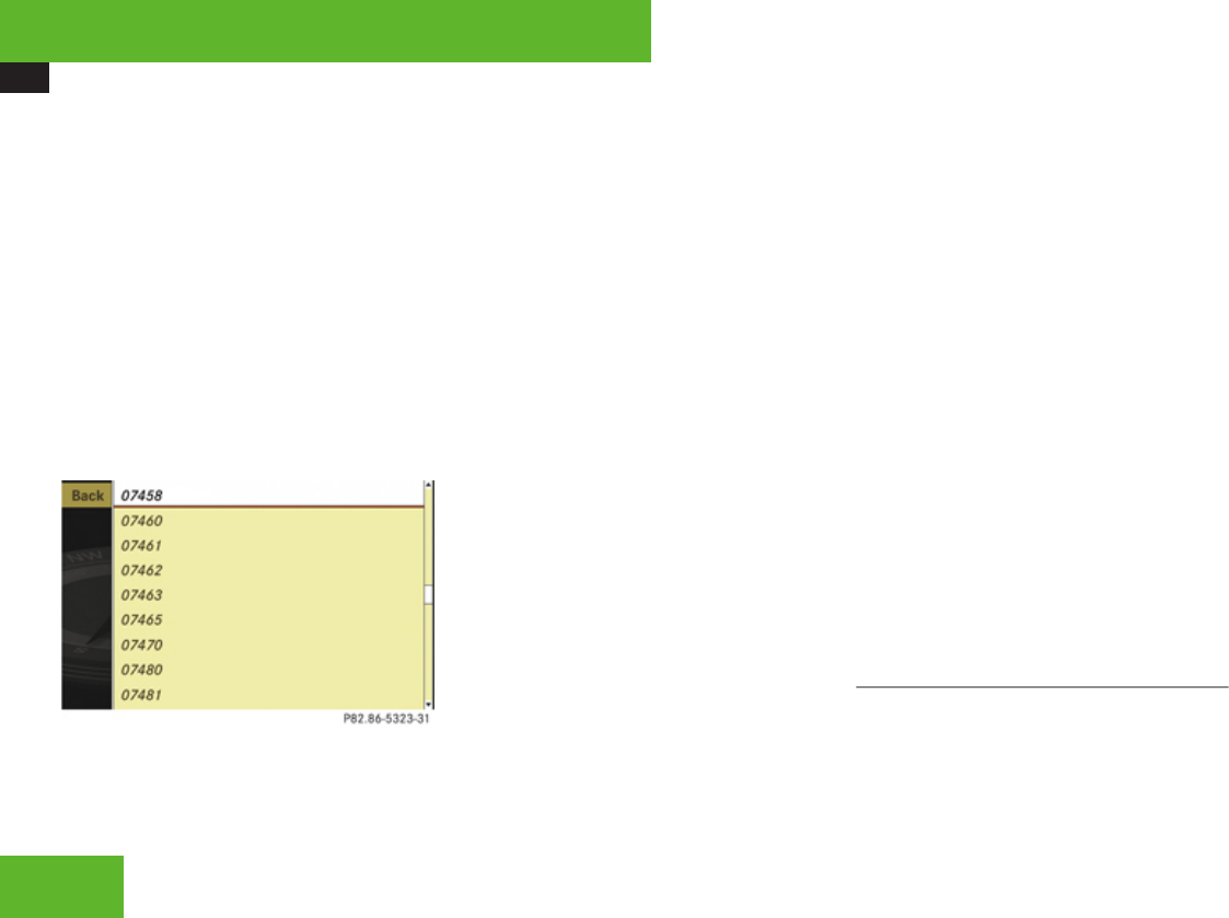
COMAND navigation system (entering a destination)
116
characters 4 disappear. You see the list of
zip codes without the input characters. Here
you can confirm the current entry or make
another selection.
During character entry, you can also manually
switch to the list of zip codes without input
characters at any time.
XSwitching manually to list of zip codes
without input characters: Slide qm.
or
XSelect d in the second line from the
bottom and press n.
List of zip codes without input characters
XSelecting a zip code: Slide qmr or rotate
ymz.
XCanceling selection: Select Back and
press n.
or
XPress back button L in the center
console (Y page 90).
XConfirming selection: Press n.
You will see the address input menu again.
It shows one of the following items of
information:
RStreet and if necessary, house number,
city, state (USA) or province (Canada)
RCity, state (USA) or province (Canada) and
zip code
RState (USA) or province (Canada) and zip
code
iThe street and, if necessary, the house
number, will then appear as soon as
COMAND can attribute the zip code to an
appropriate address.
Which of the following menu items are now
available depends on the situation, or may
depend on the data version of the digital map.
The menu items which are not available
cannot be selected.
RMap: Using the map to enter a destination
(Y page 130)
iIn this case, using the map for destination
entry is based on the city seen in the
address input menu.
RStreet: Entering a street (Y page 119)
RCenter: Entering a center (Y page 121)
RPOI: Entering a point of interest
(Y page 132)
iIn this case, entering a POI is based on the
city seen in the address input menu.
RSave: Saving a destination in the
destination memory (Y page 149)
RStart: Starting the route calculation
(Y page 127)
XContinuing or completing destination
entry: Select one of the menu items
mentioned above.
Entering a city
iYou can only enter those cities which are
saved on the digital map.
It is not possible to enter a city when you
have already entered a street which
COMAND can clearly attribute to a city.
Control systems
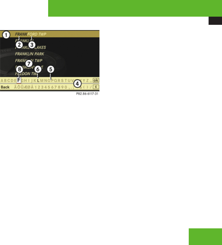
COMAND navigation system (entering a destination)
117
If COMAND cannot clearly attribute a
previously entered street to a city, only
those cities are available which have a
street of that name.
If you have not yet entered a street before
entering the city, or cities within the state
(USA) or province (Canada) previously
entered are available.
XIn the address input menu, select City.
The list of cities appears either with or
without the input characters
(Y page 118).
Whether or not the input characters appear
depends on how many cities are available
for the desired state (USA) or province
(Canada).
List of cities with input characters
When this list appears, the input characters
4 are automatically activated.
1Top list entry based on the input data up
to that point
2Characters entered by the user
3Characters automatically added by the
system
4Input characters
5Currently non-selectable characters
6Currently selectable character
7List of cities
8Currently selected character
iIn the list of input characters 4, you can
only select currently selectable characters.
Which characters are included depends on
the sequence in which you have entered
your destination and the data version of the
digital map.
The top list entry 1 at first shows either the
city in which the vehicle is currently located
or the city which best corresponds to the
input data as it has been entered up to that
point.
iThe current city is shown if:
Ryou have accepted the current state
(USA) or province (Canada) when
entering the state (USA) or province
(Canada)
Rand if you select city entry immediately
afterward
As soon as you enter a character from input
characters 4, the top list entry 1 shows the
city that best corresponds to the input data
as it has been entered up to that point. At the
same time, COMAND automatically
supplements characters 2 entered by the
user with appropriate characters 3.
XSelecting characters: Slide omp or
rotate ymz.
XConfirming character selection:
Press n.
Control systems
Z
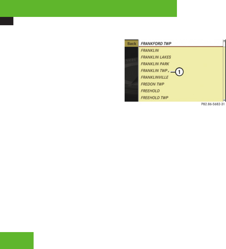
COMAND navigation system (entering a destination)
118
XDeleting individual characters:
Select ) in the bottom line and press n.
XDeleting an entire entry: Select ) in the
bottom line and press n until the entire
entry is deleted.
XCanceling an entry: Select Back in the
bottom line and press n.
or
XPress back button L in the center
console (Y page 90).
As soon as COMAND can clearly attribute the
characters entered to a city, the input
characters 4 disappear automatically. You
see the list of cities without the input
characters. Here you can confirm the current
entry or make another selection.
During character entry, you can also manually
switch to the list of cities without input
characters at any time.
XSwitching manually to the list of cities
without input characters: Slide qm.
or
XSelect d in the second line from the
bottom and press n.
List of cities without input characters
1Symbol for more selection options
XSelecting a city: Slide qmr or rotate
ymz.
XCanceling selection: Select Back and
press n.
or
XPress back button L in the center
console (Y page 90).
XConfirming selection: Press n.
Cities with symbol 1 mean that there is
more than one in the selected state (USA)
or province (Canada). Confirming one of
these cities will take you to a further sub-
selection.
If there are no other selection options, the
address input menu appears again.
It shows one of the following items of
information:
RCity and state (USA) or province (Canada)
RStreet, city and state (USA) or province
(Canada)
iThe street is visible if you have entered it
before entering the city.
Which of the following menu items are now
available depends on the situation, or may
depend on the data version of the digital map.
The menu items which are not available
cannot be selected.
RMap: Using the map to enter a destination
(Y page 130)
iIn this case, using the map for destination
entry is based on the city seen in the
address input menu.
RStreet: Entering the street (Y page 119)
RHouse No.: Entering the house number
(Y page 123)
RCenter: Entering the center (Y page 121)
RIntersection: Entering the intersection
(Y page 125)
RPOI: Entering a point of interest
(Y page 132)
Control systems
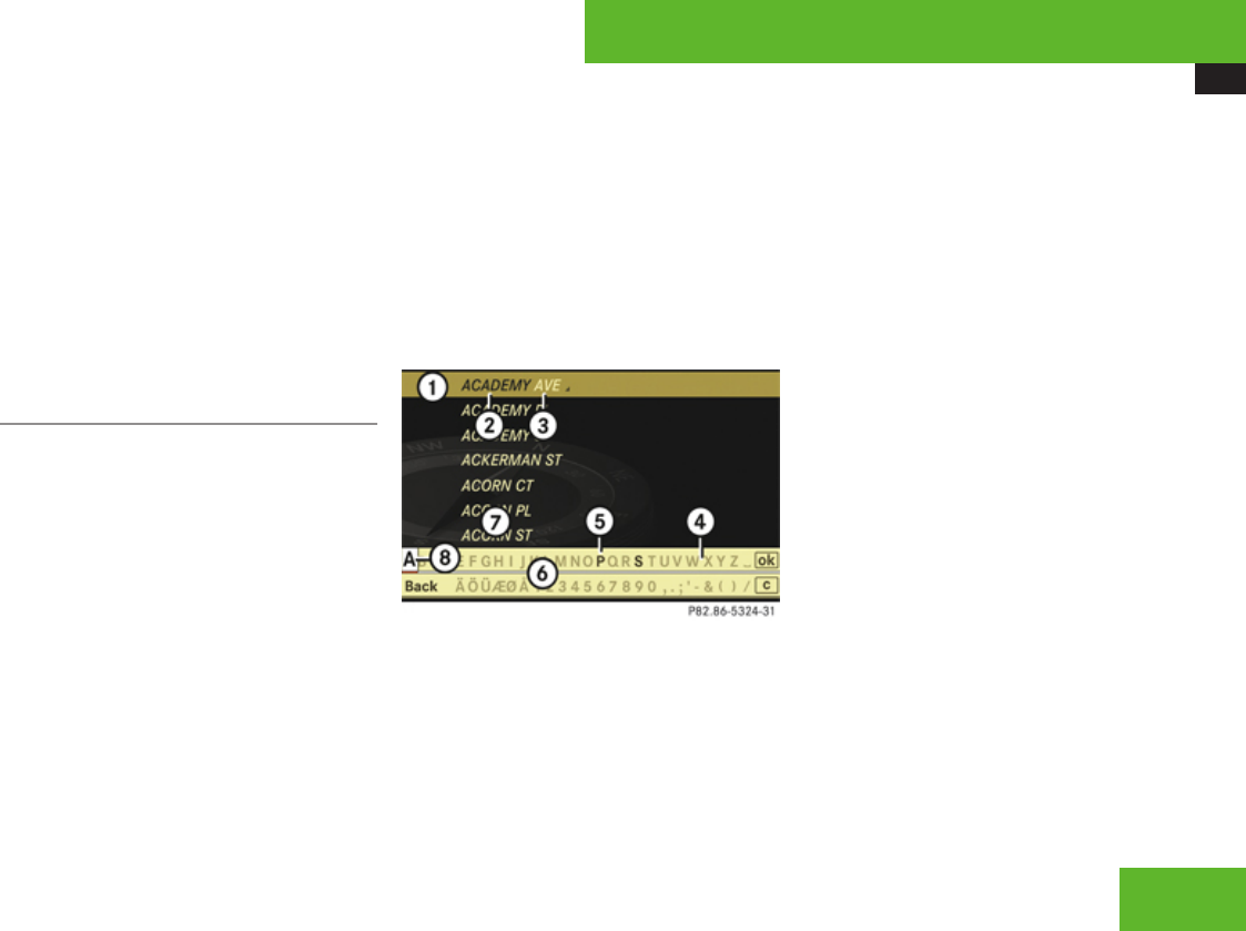
COMAND navigation system (entering a destination)
119
iIn this case, entering a POI is based on the
city seen in the address input menu.
RSave: Saving a destination in the
destination memory (Y page 149)
RStart: Starting the route calculation
(Y page 127)
XContinuing or completing destination
entry: Select one of the menu items
mentioned above.
Entering a street
iIt is not possible to enter a street if:
Ryou have already entered a center
Ryou have already entered a zip code that
COMAND can clearly attribute to a street
iYou can only enter those streets which
are saved on the digital map.
If you have not entered a city before
entering the street, only those streets
within the state (USA) or province (Canada)
previously entered are available. If you have
already entered a city, streets within that
city are available.
If you have entered a zip code before
entering the street, only those streets
within the zip code area are available.
XIn the address input menu, select Street.
The list of streets appears either with or
without the input characters
(Y page 120). Whether or not the input
characters appear depends on how many
streets are available for the selected city.
Street list with input characters
When this list appears, the input characters
6 are automatically activated.
1Top list entry based on the input data up
to that point
2Characters entered by the user
3Characters automatically added by the
system
4Currently non-selectable characters
5Currently selectable character
6Input characters
7Street list
8Currently selected character
iIn the list of input characters 6, you can
only select currently selectable characters.
Which characters are included depends on
the sequence in which you have entered
your destination and the data version of the
digital map.
The top list entry 1 first shows the street first
alphabetically and best corresponds to the
input data as it has been entered up to that
point.
As soon as you enter a character from input
characters 6, the top list entry 1 shows the
street which best corresponds to the input
data as it has been entered up to that point.
At the same time, COMAND automatically
supplements characters 2 entered by the
user with appropriate characters 3.
XSelecting characters: Slide omp or
rotate ymz.
XConfirming character selection:
Press n.
Control systems
Z
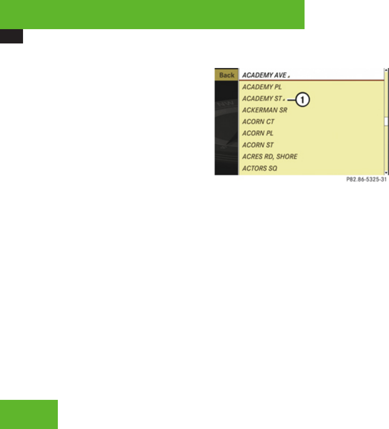
COMAND navigation system (entering a destination)
120
XDeleting individual characters:
Select ) in the bottom line and press n.
XDeleting an entire entry: Select ) in the
bottom line and press n until the entire
entry is deleted.
XCanceling an entry: Select Back in the
bottom line and press n.
or
XPress back button L in the center
console (Y page 90).
As soon as COMAND can clearly attribute the
characters entered to a street, the input
characters 6 disappear. You see the street
list without the input characters. Here you
can confirm the current entry or make
another selection.
During character entry, you can also manually
switch to the street list without input
characters at any time.
XSwitching manually to the street list
without input characters: Slide qm.
or
XSelect d in the second line from the
bottom and press n.
Street list without input characters
1Symbol for more selection options
XSelecting a street: Slide qmr or rotate
ymz.
or
XEnter a street number with the telephone
keypad using the R - 9 buttons
(Y page 85).
iExample: Pressing button 2 jumps to
the 2nd Avenue.
XCanceling selection: Select Back and
press n.
or
XPress back button L in the center
console (Y page 90).
XConfirming selection: Press n.
Streets with symbol 1 run through several
suburbs. Confirming one of these streets
takes you to a further sub-selection.
If there are no other selection options, the
address input menu appears again after the
confirmation.
It shows one of the following items of
information:
RStreet and state (USA) or province
(Canada)
RStreet, city and state (USA) or province
(Canada)
iThe city is visible if you have entered it
before entering the street, or if COMAND
can clearly attribute the street entered to a
city.
Which of the following menu items are now
available depends on the situation, or may
depend on the data version of the digital map.
The menu items which are not available
cannot be selected.
RMap: Using the map to enter a destination
(Y page 130)
Control systems
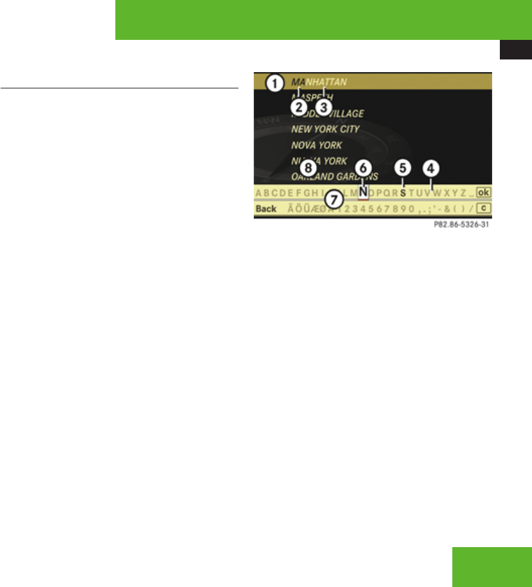
COMAND navigation system (entering a destination)
121
iIn this case, using the map for destination
entry is based on the city seen in the
address input menu.
RHouse No.: Entering the house number
(Y page 123)
RIntersection: Entering the intersection
(Y page 125)
iEntering an intersection is restricted to
streets within the vicinity of the street
entered.
RPOI: Entering a point of interest
(Y page 132)
iIn this case, entering a POI is based on the
city seen in the address input menu.
RSave: Saving a destination in the
destination memory (Y page 149)
RStart: Starting the route calculation
(Y page 127)
XContinuing or completing destination
entry: Select one of the menu items
mentioned above.
Entering a center
iIt is not possible to enter a center if:
Ryou have not yet entered a city
Ryou have already entered a street
Ryou have already entered a zip code that
COMAND can clearly attribute to an
address
You can only enter those centers which are
saved on the digital map.
Depending on the previous entry, centers
are available either for the city entered or
the zip code area entered.
XIn the address input menu, select Center.
The list of centers appears either with or
without the input characters
(Y page 122). Whether or not the input
characters appear depends on how many
centers are available in the selected city.
List of centers with input characters
When this list appears, the input characters
7 are automatically activated.
1Top list entry based on the input data up
to that point
2Characters entered by the user
3Characters automatically added by the
system
4Currently non-selectable characters
5Currently selectable character
6Currently selected character
7Input characters
8List of centers
iIn the list of input characters 7, you can
only select currently selectable characters.
Which characters are included depends on
the sequence in which you have entered
your destination and the data version of the
digital map.
Control systems
Z
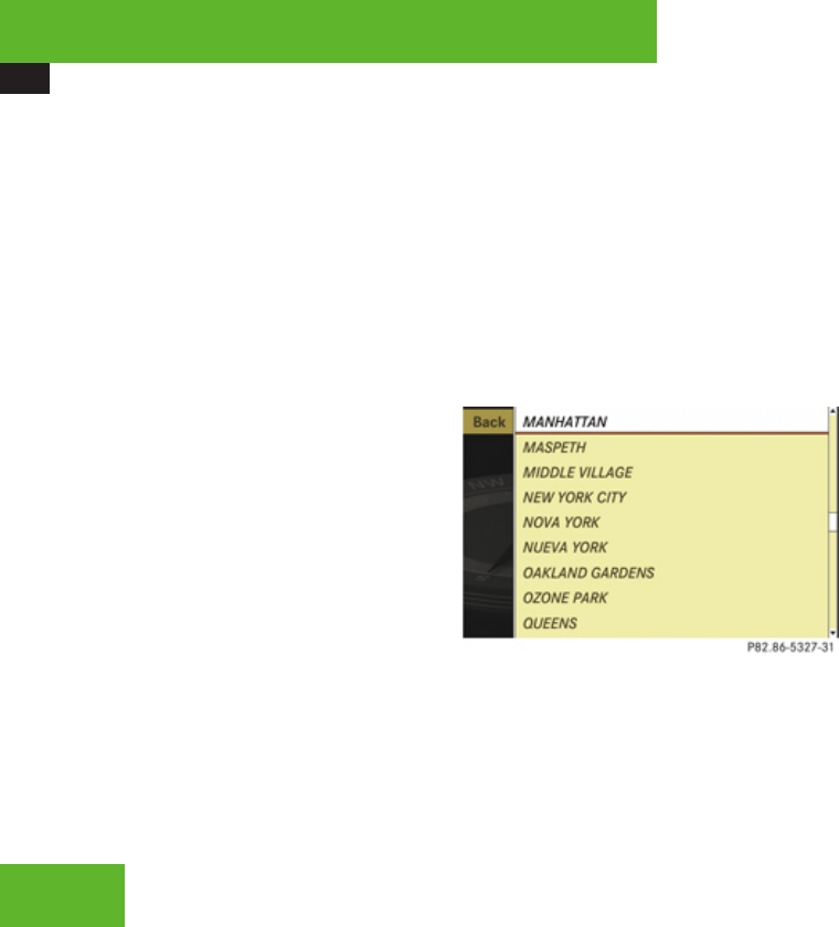
COMAND navigation system (entering a destination)
122
While the characters are being selected as
described below, top list entry 1 always
shows the center which best corresponds to
the input data as it has been entered up to
that point. At the same time, COMAND
automatically supplements characters 2
entered by the user with appropriate
characters 3.
XSelecting characters: Slide omp or
rotate ymz.
XConfirming character selection:
Press n.
XDeleting individual characters:
Select ) in the bottom line and press n.
XDeleting an entire entry: Select ) in the
bottom line and press n until the entire
entry is deleted.
XCanceling an entry: Select Back in the
bottom line and press n.
or
XPress back button L in the center
console (Y page 90).
As soon as COMAND can clearly attribute the
characters entered to a center, input
characters 7 disappear. You see the list of
centers without the input characters. Here
you can confirm the current entry or make
another selection.
During character entry, you can also manually
switch to the list of centers without input
characters at any time.
XSwitching manually to the list of
centers without input characters: Slide
qm.
or
XSelect d in the second line from the
bottom and press n.
List of centers without input characters
XSelecting a center: Slide qmr or rotate
ymz.
XCanceling selection: Select Back and
press n.
or
XPress back button L in the center
console (Y page 90).
XConfirming selection: Press n.
After the confirmation, the address input
menu appears again. It shows the center,
city and state (USA) or province (Canada).
Which of the following menu items are now
available may depend on the data version
of the digital map. The menu items which
are not available cannot be selected.
RMap: Using the map to enter a destination
(Y page 130)
iIn this case, using the map for destination
entry is based on the center seen in the
address input menu.
RPOI: Entering a point of interest
(Y page 132)
iIn this case, entering a point of interest is
based on the center seen in the address
input menu.
Control systems
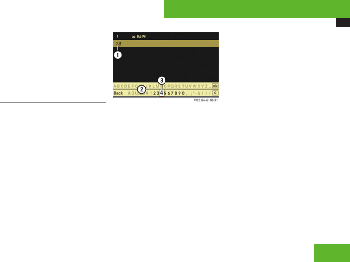
COMAND navigation system (entering a destination)
123
RSave: Saving a destination in the
destination memory (Y page 149)
RStart: Starting the route calculation
(Y page 127)
XContinuing or completing destination
entry: Select one of the menu items
mentioned above.
Entering a house number
iThe house number can only be entered
after the street has been entered.
You can only enter those house numbers
which are saved on the digital map. The
digital map does not contain all house
numbers for all streets.
How the house number is entered depends
on whether you have already entered just the
street or both the street and the city
(Y page 124).
With only the street entered previously
When COMAND can clearly allocate the
street to a city, the house number appears
without input characters. Select a house
number from the list (Y page 125).
When COMAND cannot clearly allocate the
street to a city, a house number screen
appears. You can now enter a house number.
1Numbers entered by the user
2Input characters
3Currently selected number
XSelecting numbers: Slide omp or rotate
ymz.
XConfirming number selection: Press n.
or
XEntering a number with the telephone
keypad using the R - 9 buttons
(Y page 85).
XDeleting individual numbers: Select )
in the bottom line and press n.
XDeleting an entire entry: Select ) in the
bottom line and press n until the entire
entry is deleted.
XCanceling an entry: Select Back in the
bottom line and press n.
or
XPress back button L in the center
console (Y page 90).
XConfirming entry: Select d in the
second line from the bottom and press n.
If COMAND cannot clearly attribute the
house number to a city, the city input menu
appears.
Entering city: Proceed as described in the
“Entering a city” section (Y page 116).
After the city has been entered, the address
input menu appears again.
If COMAND can clearly attribute the house
number to a city, the address input menu
also appears.
In both cases, the address input menu
shows the house number, street, city and
state (USA) or province (Canada).
Which of the following menu items are now
available may depend on the data version of
the digital map. The menu items which are not
available cannot be selected.
RMap: Using the map to enter a destination
(Y page 130)
Control systems
Z
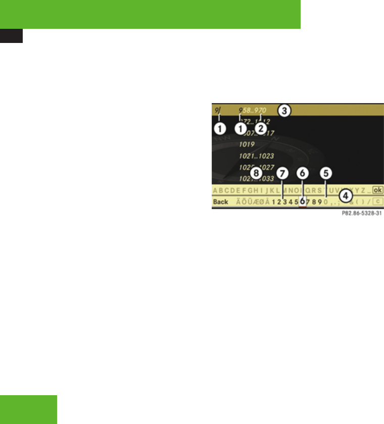
COMAND navigation system (entering a destination)
124
iIn this case, using the map for destination
entry is based on the city seen in the
address input menu.
RPOI: Entering a point of interest
(Y page 132)
iIn this case, entering a POI is based on the
city seen in the address input menu.
RSave: Saving a destination in the
destination memory (Y page 149)
RStart: Starting the route calculation
(Y page 127)
XContinuing or completing destination
entry: Select one of the menu items
mentioned above.
With the street and city previously
entered
XIn the address input menu, select House
No..
The list of house numbers appears either
with or without the input characters
(Y page 125). Whether or not the input
characters appear depends on how many
house numbers are available in the
selected street.
List of house numbers with input
characters
When this list appears, the input characters
4 are automatically activated.
1Numbers entered by the user
2Numbers automatically added by the
system
3Top list entry based on the input data up
to that point
4Input characters
5Currently non-selectable numbers
6Currently selected number
7Currently selectable numbers
8List of house numbers
iIn the list of input characters 4, you can
only select currently selectable characters.
Which characters are included depends on
the sequence in which you have entered
your destination and the data version of the
digital map.
While the numbers are being selected as
described below, the top list entry 3 always
shows the house number which best
corresponds to the input data as it has been
entered up to that point. At the same time,
COMAND automatically supplements
numbers 1 entered by the user with
appropriate numbers 2.
XSelecting numbers: Slide omp or rotate
ymz.
or
XEntering a number with the telephone
keypad using the R - 9 buttons
(Y page 85).
XConfirming number selection: Press n.
XDeleting individual numbers: Select )
in the bottom line and press n.
XDeleting an entire entry: Select ) in the
bottom line and press n until the entire
entry is deleted.
Control systems
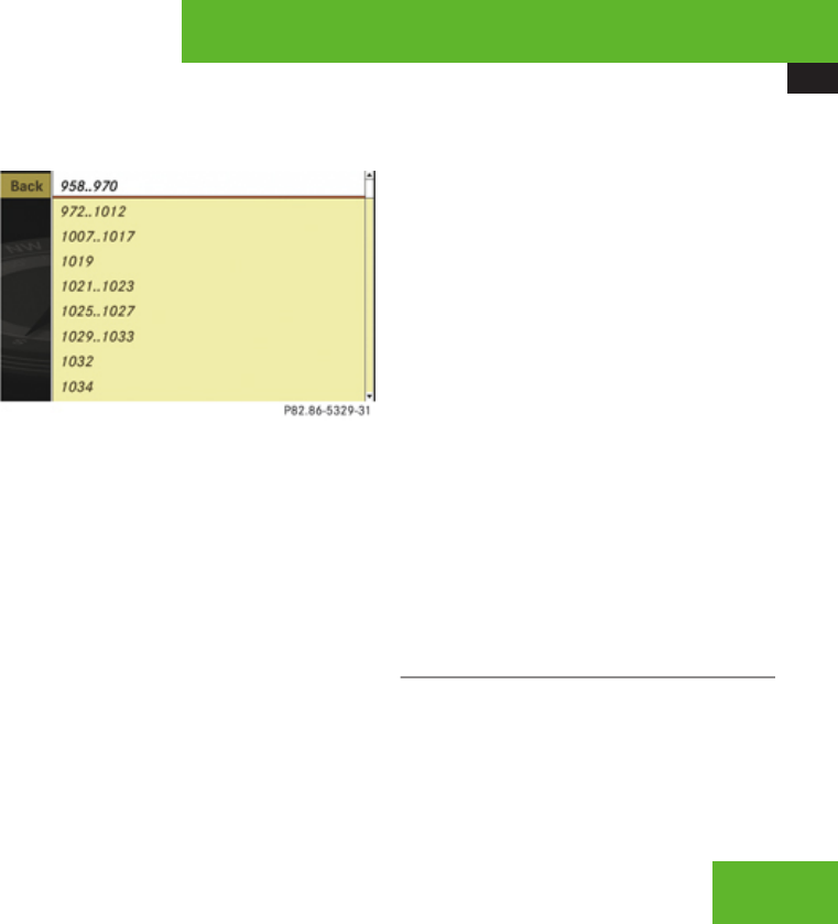
COMAND navigation system (entering a destination)
125
XCanceling an entry: Select Back in the
bottom line and press n.
or
XPress back button L in the center
console (Y page 90).
As soon as COMAND can clearly attribute the
numbers entered to a house number, the
input characters 4 disappear. You see the
list of house numbers without the input
characters. Here you can confirm the current
entry or make another selection.
During number entry, you can also manually
switch to the list of house numbers without
input characters at any time.
XSwitching manually to the list of house
numbers without input characters:
Slide qm.
or
XSelect d in the second line from the
bottom and press n.
List of house numbers without input
characters
XSelecting house numbers: Slide qmr or
rotate ymz.
XCanceling selection: Select Back and
press n.
or
XPress back button L in the center
console (Y page 90).
XConfirming selection: Press n.
After the confirmation, the address input
menu appears again. It shows the house
number, street, city and state (USA) or
province (Canada).
Which of the following menu items are now
available may depend on the data version of
the digital map. The menu items which are not
available cannot be selected.
RMap: Using the map to enter a destination
(Y page 130)
iIn this case, using the map for destination
entry is based on the city seen in the
address input menu.
RPOI: Entering a point of interest
(Y page 132)
iIn this case, entering a POI is based on the
city seen in the address input menu.
RSave: Saving a destination in the
destination memory (Y page 149)
RStart: Starting the route calculation
(Y page 127)
XContinuing or completing destination
entry: Select one of the menu items
mentioned above.
Entering an intersection
iThe intersection can only be entered after
the street has been entered.
You can only enter those intersections
which are saved on the digital map.
Control systems
Z
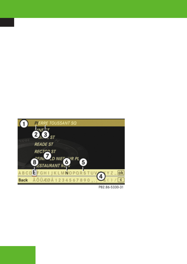
COMAND navigation system (entering a destination)
126
XIn the address input menu, select
Intersection.
The list of intersections appears either with
or without the input characters
(Y page 127). Whether or not the input
characters appear depends on how many
intersections are available for the selected
street.
List of intersections with input characters
When this list appears, the input characters
4 are automatically activated.
1Top list entry based on the input data up
to that point
2Characters entered by the user
3Characters automatically added by the
system
4Input characters
5Currently non-selectable characters
6Currently selectable character
7List of intersections
8Currently selected character
iIn the list of input characters 4, you can
only select currently selectable characters.
Which characters are included depends on
the sequence in which you have entered
your destination and the data version of the
digital map.
While the characters are being selected as
described below, the top list entry 1 always
shows the intersection which best
corresponds to the input data as it has been
entered up to that point.
At the same time, COMAND automatically
supplements characters 2 entered by the
user with appropriate characters 3.
XSelecting characters: Slide omp or
rotate ymz.
XConfirming character selection:
Press n.
XDeleting individual characters:
Select ) in the bottom line and press n.
XDeleting an entire entry: Select ) in the
bottom line and press n until the entire
entry is deleted.
XCanceling character entry: Select Back
in the bottom line and press n.
or
XPress back button L in the center
console (Y page 90).
As soon as COMAND can clearly attribute the
characters entered to an intersection, the
input characters 4 disappear. You see the
list of intersections without the input
characters. Here you can confirm the current
entry or make another selection.
During character entry, you can also manually
switch to the list of intersections without
input characters at any time.
XSwitching manually to the list of
intersections without input
characters: Slide qm.
or
XSelect d in the second line from the
bottom and press n.
Control systems
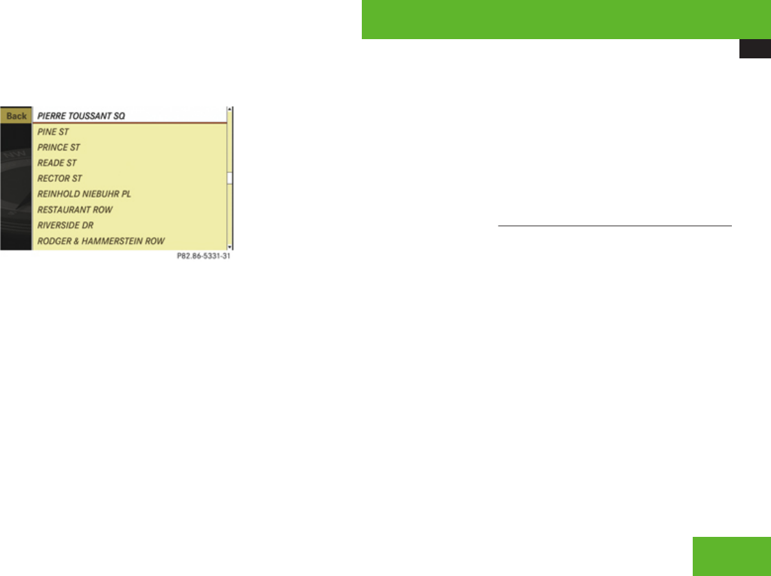
COMAND navigation system (entering a destination)
127
List of intersections without input
characters
XSelecting an intersection: Slide qmr or
rotate ymz.
XConfirming selection: Press n.
Either the address input menu appears
again, or the city input menu.
iThe city input menu appears if the
intersection entered cannot be clearly
attributed to a city.
XCanceling selection: Select Back and
press n.
or
XPress back button L in the center
console (Y page 90).
XIf the city input menu appears: Enter a
city.
iA detailed description of how to enter a
city can be found in the “Entering a city”
section (Y page 116).
After the city has been entered, the address
input menu appears again.
Which of the following menu items are now
available may depend on the data version of
the digital map. The menu items which are not
available cannot be selected.
RMap: Using the map to enter a destination
(Y page 130)
iIn this case, using the map for destination
entry is based on the city seen in the
address input menu.
RPOI: Entering a point of interest
(Y page 132)
iIn this case, entering a POI is based on the
city seen in the address input menu.
RSave: Saving a destination in the
destination memory (Y page 149)
RStart: Starting the route calculation
(Y page 127)
XContinuing or completing destination
entry: Select one of the menu items
mentioned above.
Starting the route calculation
iYou cannot start the route calculation
until all the necessary address data has
been entered.
iWith Change Name you can change the
name of the chosen entry from the
destination memory before starting the
route calculation.
XAfter entering the destination, select
Start.
The route calculation will start if route
guidance has not already been activated.
If route guidance has already been
activated, a prompt will appear asking
Control systems
Z
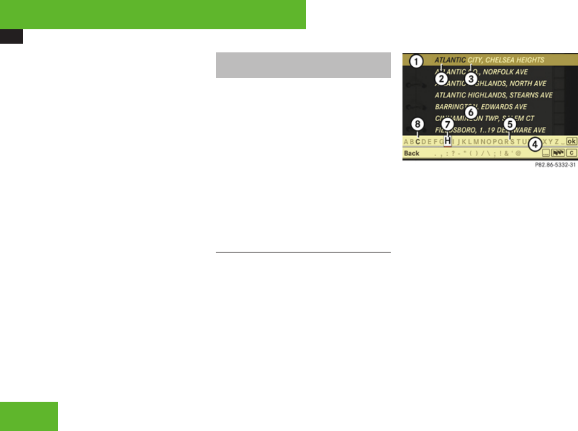
COMAND navigation system (entering a destination)
128
whether you want to end the current route
guidance.
XSelect Yes or No.
If you select Yes, COMAND will stop the
route guidance and start the route
calculation for the new destination.
If you select No, COMAND will continue
with the active route guidance.
The new destination is discarded.
During the route calculation, an arrow will
indicate the linear direction to the
destination. Below this, you will see the
message Calculating Route.
Once the route has been calculated, route
guidance begins (Y page 139).
iRoute calculation requires a certain
amount of time. The time depends on the
distance from the destination, for example.
COMAND calculates the route using the
digital map data. The calculated route may
differ from the actual road situation, e. g.
due to road construction or incomplete
map data. Please make sure that you
observe the notes about the digital map
(Y page 100).
Entering a destination from the
destination memory
XSelect Navi £ Destination £ From
Memory.
The destination memory list appears either
with or without the input characters
(Y page 129). Whether the input
characters appear depends on the number
of entries in the destination memory.
iThe destination memory always contains
an entry called My Address. You can save
your home address, for example, under this
entry (Y page 151).
Destination memory list with input
characters
When this list appears, the input characters
4 are automatically activated.
1Top list entry based on the input data up
to that point
2Characters entered by the user
3Characters automatically added by the
system
4Input characters
5Currently non-selectable characters
6Destination memory list
7Currently selected character
8Currently selectable characters
iIn the list of input characters 4, you can
only select currently selectable characters.
Which characters are included depends on
the sequence in which you have entered
your destination and the content of the
destination memory.
Control systems
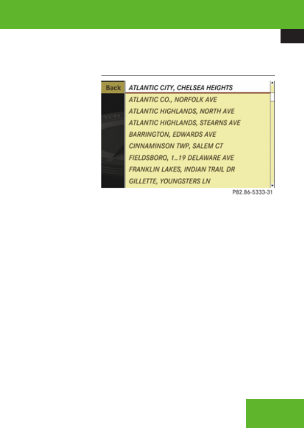
COMAND navigation system (entering a destination)
129
While the characters are being selected as
described below, the top list entry 1 always
shows the destination which best
corresponds to the input data as it has been
entered up to that point.
At the same time, COMAND automatically
supplements characters 2 entered by the
user with appropriate characters 3.
XChanging language for the input
characters: Select !.
XSelect desired language.
XChanging character set for the input
characters: Select #.
Depending on the previous setting, you will
change to letters with special characters or
to numbers with special characters.
XSelecting characters: Slide omp or
rotate ymz.
XConfirming character selection:
Press n.
XDeleting individual characters:
Select ) in the bottom line and press n.
XDeleting an entire entry: Select ) in the
bottom line and press n until the entire
entry is deleted.
XCanceling an entry: Select Back in the
bottom line and press n.
or
XPress back button L in the center
console (Y page 90).
As soon as COMAND can clearly attribute the
characters entered to a destination, the input
characters 4 disappear. You see the
destination memory list without input
characters. Here you can confirm the current
entry or make another selection.
You can also manually switch to the
destination memory list without input
characters at any time.
XSwitching manually to the destination
memory list without input characters:
Slide qm.
or
XSelect d in the second line from the
bottom and press n.
Destination memory list without input
characters
XSelecting a destination: Slide qmr or
rotate ymz.
XCanceling selection: Press back button
L in the center console (Y page 90).
or
XSelect Back and press n.
iThe Back menu item is only present if this
list was called up from the list with input
characters.
XConfirming selection: Press n.
XStarting route calculation: Select
Start, see also (Y page 127).
Control systems
Z
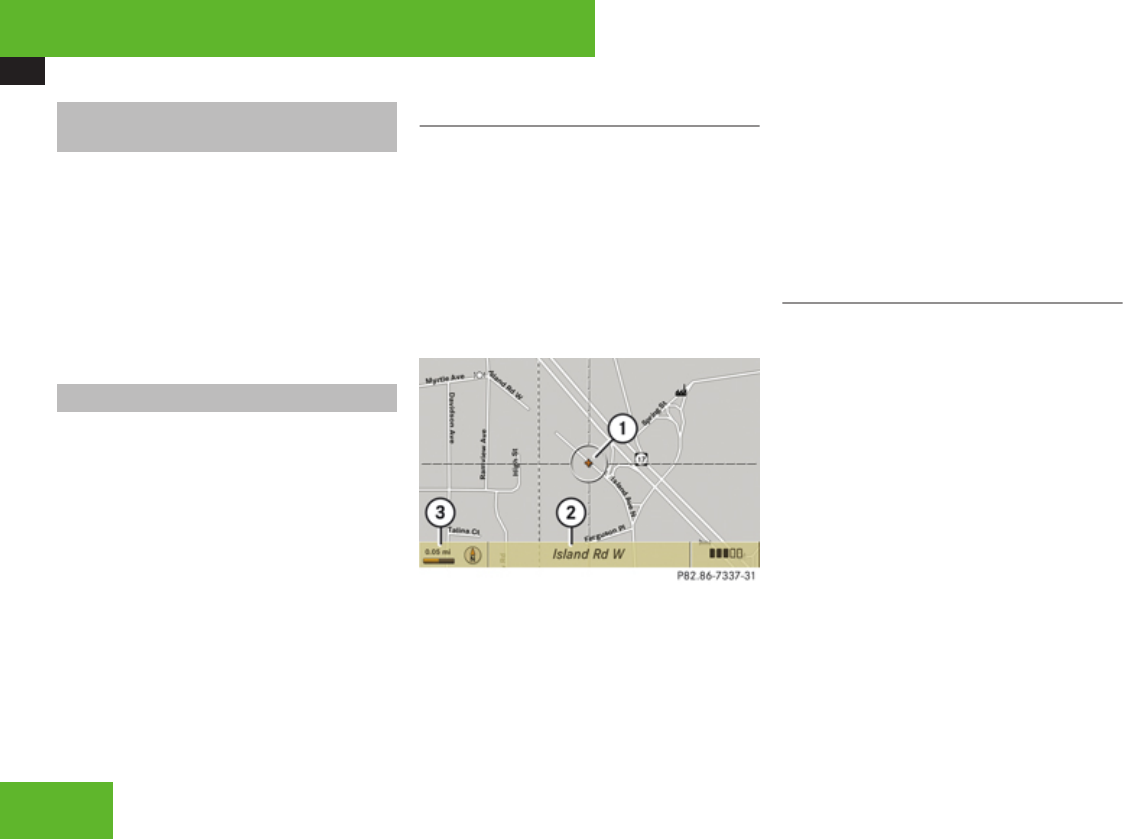
COMAND navigation system (entering a destination)
130
Entering a destination from the list of
last destinations
XSelect Navi £ Destination £ From
Last Destinations.
The list of last destinations appears. The
most recent destination is at the top of the
list.
XSelect desired destination.
XStarting route calculation: Select
Start, see also (Y page 127).
Entering a destination from the map
iDepending on the factory settings of the
vehicle, it may not be possible to enter a
destination while the vehicle exceeds a
preset speed. As soon as the vehicles
speed drops to below the preset speed, the
function is available again. You can enter a
destination via the map if the digital map
does not contain the address of the
destination, but the destination must be
within the area of the digital map.
Calling up the map
XIn the address input menu, select Map
(Y page 112).
You will see the map with a cross hair. The
map is set to the address set in the address
input menu.
or
XSelect Navi £ Destination £ Via
Map.
You will see the map with a cross hair.
1Cross hair
2Details of the cross hair position
3Map scale
iDisplay 2 may be the name of a road, for
example, provided the digital map contains
the necessary data.
If no data is available, display 2 shows:
Rthe coordinates if the geocoordinate
display is switched on (Y page 110)
Rno display if the geocoordinate display is
switched off (Y page 110)
Moving the map and selecting the
destination
XMoving map: Slide qmr, omp or wmx.
XAdjusting map scale: Rotate ymz.
Rotating clockwise enlarges the map,
rotating counterclockwise reduces it.
XSelecting a destination: Press n.
If the cross hair is located off the edge of
the digital map, a route cannot be
calculated to this destination and you will
see the message The destination is
located off the map..
XSelect OK.
XMove the map and select a destination
again.
If the destination is within the limits of the
digital map, COMAND attempts to attribute
the destination to the map, which can take
approximately 2 seconds.
If the destination can be attributed, you will
see the address of the destination. If not,
Control systems

COMAND navigation system (entering a destination)
131
you will see the display Destination from
map.
XStarting route calculation: Select
Start, see also (Y page 127).
Entering a stopover
iWhen route guidance is active, you can
enter a stopover. Stopovers can be
predefined destinations from the following
predefined categories:
RMercedes-Benz Center
RHospital
RGas station
RParking lot
RRestaurant
However, you can also enter destinations
other than the predefined ones.
iYou can use the stopover function to
influence the route guidance calculation to
the main destination. When you have
reached your stopover, COMAND
automatically calculates the route to the
main destination.
Entering predefined destinations
XSelect Navi £ Destination £
Stopover.
If a stopover has already been entered, you
can change it.
Changing: Select Change Stopover.
You can now select a category.
XSelecting a category: Select category,
e. g. Gas station.
COMAND first looks for destinations within
the immediate vicinity of the vehicle and
near the vehicle’s route. If there are no
destinations available there, COMAND
searches for destinations in an area around
the vehicle position.
If COMAND does not find any destinations,
you will see a message to this effect.
Select OK.
You can now select a different category.
If COMAND finds destinations, you will see
a list of the destinations and details of how
far away they are in the right-hand side of
the display. The information about how far
away the destinations are can take a few
seconds to be displayed.
The left-hand part of the display shows the
destinations on the map. The destination
marked in the list is highlighted in the map.
XSelecting a destination: Select the
desired destination from list.
The address of the destination appears.
XStarting route calculation: Select
Start, see also (Y page 127).
Entering another destination as a
stopover
XSelect Navi £ Destination £
Stopover.
XEntering: Select Other.
You can select between the following menu
items:
RAddress Entry
RFrom Memory
RFrom Last Destinations
RFrom POIs
XSelect a menu item.
Subsequent destination entries may differ,
depending on your selection:
RAddress Entry selection:
XEnter a destination by address
(Y page 112).
RFrom Memory selection:
Control systems
Z

COMAND navigation system (Point of interest entry)
132
XEnter a destination from the
destination memory (Y page 128).
RFrom Last Destinations selection:
XEnter a destination from the list of last
destinations (Y page 130).
RFrom POIs selection:
XEnter a special destination
(Y page 132).
XStarting route calculation: After entering
a destination, select Start (Y page 127).
Changing a stopover
If a stopover has already been entered, you
can change it.
XSelect Navi £ Destination £
Stopover £ Change Stopover.
XEnter another destination as a stopover.
Deleting the stopover
If a stopover has already been entered, you
can delete it.
XSelect Navi £ Destination £
Stopover £ Delete Stopover.
COMAND deletes the stopover and
calculates the route to the main
destination.
COMAND navigation system (Point of
interest entry)
Entering a POI in the surrounding area
XIn the map view while the menu system is
displayed, select Destination £ From
POIs £ Current Position
(Y page 107).
XContinue with designating the POI category
(Y page 133).
Entering a POI in the surroundings of
a given city
Option 1
XIn the map view while the menu system is
displayed, select Destination £ From
POIs £ Other City (Y page 107).
XIf necessary, enter state (USA)
(Y page 112) or province (Canada)
(Y page 114).
XEntering city: Select City.
The city input menu appears.
Control systems

COMAND navigation system (Point of interest entry)
133
XThen proceed as described in the “Entering
a city” section (Y page 116).
XAfter entering the city, continue with
designating the POI category
(Y page 133).
Option 2
XEnter an address in the address input menu
(Y page 112).
XSelect POI.
XContinue with designating the POI category
(Y page 133).
Entering a POI in a different region
iThis function gives you quick access to
POIs which are of national interest in the
state (USA) or province (Canada) you have
selected. The following categories may be
available:
RAIRPORT
RBORDER CROSSING
RHIGHWAY ACCESS
Not all categories are available in all states
(USA) or provinces (Canada).
XIn the map view while the menu system is
displayed, select Destination £ From
POIs £ Global POI (Y page 107).
The category list appears. The state (USA)
or province (Canada) currently selected is
shown in the first list entry.
XSelecting another state (USA) or
province (Canada): Select the first list
entry.
A list of states/provinces appears.
XSelect desired state (USA) or province
(Canada).
If there are no POIs for the selected state
(USA) or province (Canada), you will see a
corresponding message.
Closing message: Select OK.
You can again select a state (province).
If there are POIs, you will see the category
list again.
XProceed as described in the “Selecting a
category” paragraph in the “Main category
list without input characters” section
(Y page 135).
Designating a POI category
The categories and POIs available depend on
the distance from the vehicle position you
have set for the POI.
RPOI in the surrounding area:
categories sorted alphabetically and POIs
sorted by distance within a radius of about
12 mi around the vehicle position are
available. You can extend the search radius
using the list options (Y page 137).
RPOI within a given city:
If you have only entered the state (USA) or
province (Canada) and the city,
alphabetically sorted categories and
alphabetically sorted POIs within the city
are available.
If you have entered more than the state
(USA) or province (Canada) and the city,
alphabetically sorted categories and POIs
sorted by distance within a radius of about
12 mi around the address entered are
available. You can extend the search radius
and the category selection using the list
options (Y page 137).
RPOIs in a different region:
Alphabetically sorted categories and
alphabetically sorted POIs are available.
Control systems
Z
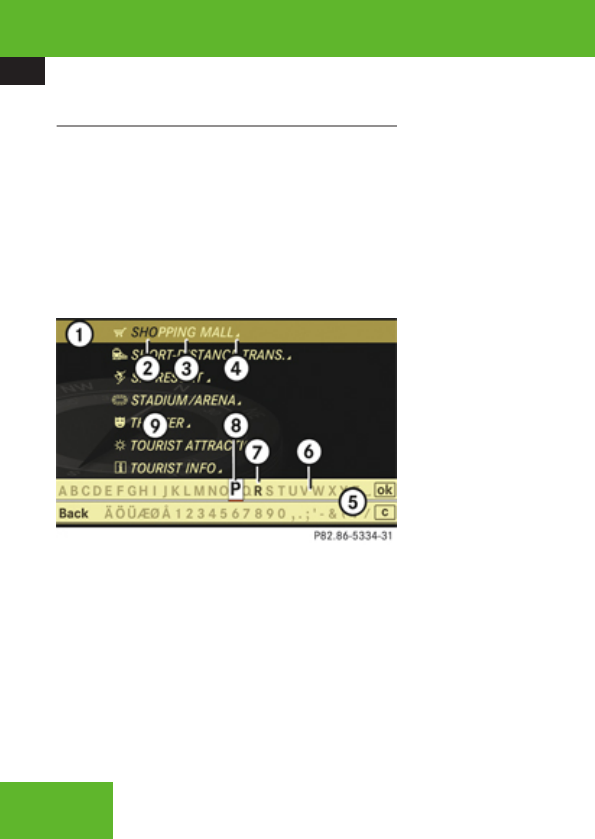
COMAND navigation system (Point of interest entry)
134
Entering a category
Depending on the number of available
categories, the main category list appears for
category entry either with or without input
characters (Y page 135).
Main category list with input characters
When this list appears, the input characters
5 are automatically activated.
1Top list entry based on the input data up
to that point
2Characters entered by the user
3Characters automatically added by the
system
4Symbol for available POIs or other
available subcategories
5Input characters
6Currently non-selectable characters
7Currently selectable character
8Currently selected character
9Main category list
iIn the list of input characters 5, you can
only select currently selectable characters.
Which characters are included depends on
the sequence in which you have entered
your destination and the data version of the
digital map.
While the characters are being selected as
described below, the top list entry 1 always
shows the category which best corresponds
to the input data as it has been entered up to
that point.
At the same time, COMAND automatically
supplements characters 2 entered by the
user with appropriate characters 3.
XSelecting characters: Slide omp or
rotate ymz.
XConfirming character selection:
Press n.
XDeleting individual characters:
Select ) in the bottom line and press n.
XDeleting an entire entry: Select ) in the
bottom line and press n until the entire
entry is deleted.
XCanceling an entry: Select Back in the
bottom line and press n.
or
XPress back button L in the center
console (Y page 90).
As soon as COMAND can clearly attribute the
characters entered to a category, the input
characters 5 disappear. You see the list of
main categories without the input characters.
Here you can confirm the current entry or
make another selection.
You can also manually switch to the main
category list without input characters at any
time.
XSwitching manually to the main
category list without input characters:
Slide qm.
or
XSelect d in the second line from the
bottom and press n.
Control systems
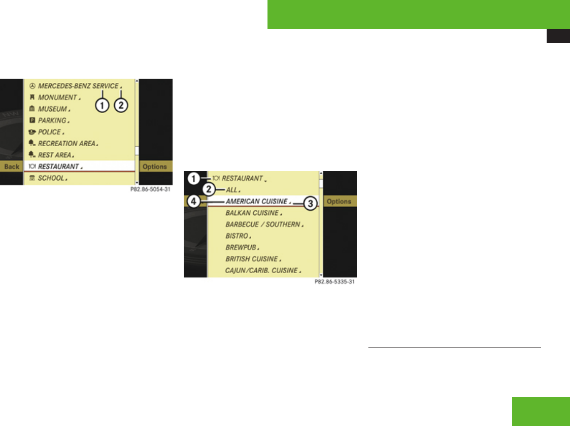
COMAND navigation system (Point of interest entry)
135
Main category list without input
characters
Example illustration: Main category list for POIs in
the surrounding area
1Category
2Symbol for available POIs or other
available subcategories
XSelecting a main category: Slide qmr or
rotate ymz.
XCanceling selection: Select Back and
press n.
or
XPress back button L in the center
console (Y page 90).
XConfirming selection: Press n.
Main categories with symbol 2 contain
either POIs or subcategories. Further
operation depends on whether the
selected main category contains
subcategories or only POIs.
Selected main category contains
subcategories:
Selecting such a main category opens a list
of subcategories. The illustration below
shows by way of example the RESTAURANT
main category with available subcategories
4.
1Main category
2To show all POIs for all subcategories
under category 1
3Symbol for available POIs
4Subcategory
XSelecting a subcategory: Slide qmr or
rotate ymz.
XCanceling selection: Select Back and
press n.
or
XPress back button L in the center
console (Y page 90).
XConfirming selection: Press n.
After selecting a subcategory, a list of POIs
appears. It contains the POIs available
within the search radius of the
subcategory.
iIf you have selected list item 2, the POI
list contains all POIs for all subcategories
within the search radius of main category
1.
Selected main category contains no
subcategories, but only POIs:
Selecting such a main category immediately
opens a list of POIs. The POI list contains the
available POIs within the search radius of the
main category.
POI list
Depending on the situation, COMAND first
shows the following list or the POI list with
input characters.
Control systems
Z
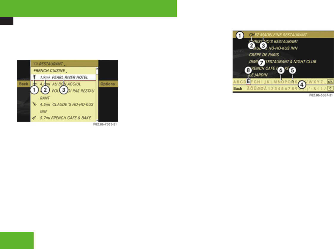
COMAND navigation system (Point of interest entry)
136
The illustration below shows by way of
example the POI list for the RESTAURANT main
category, FRENCH CUISINE subcategory
within the surrounding area.
1Compass heading to the destination
2Linear distance to the destination
3Special destination
iDisplays 1 and 2 are not visible if you
have already entered a POI within a
particular city. Displays 1 and 2 are
static; they do not change while you are
driving.
In the POI list, you can either select a POI or
enter the name of the POI.
Selecting a POI
XSelect desired POI.
The POI list disappears and the address of
the POI appears.
XBack to POI list: Select Back and
press n.
or
XPress back button L in the center
console (Y page 90).
XStarting route calculation: Select
Start, see also (Y page 127).
Entering name of POI
XSelect Options £ Spell.
The POI list appears with input characters;
the input characters are automatically
activated.
POI list with input characters
iFor POIs in other regions, this list also
shows the compass heading to the
destination as well as the linear distance to
the destination, as in the previous
illustration.
1Top list entry based on the input data up
to that point
2Characters entered by the user
3Characters automatically added by the
system
4Input characters
5Currently selectable character
6Currently non-selectable characters
7POI list
8Currently selected character
iIn the list of input characters 4, you can
only select currently selectable characters.
Which characters are included depends on
the sequence in which you have entered
your destination and the data version of the
digital map.
Control systems
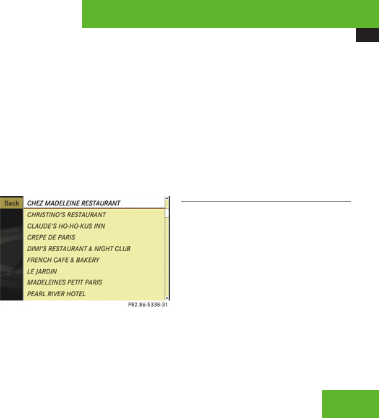
COMAND navigation system (Point of interest entry)
137
While the characters are being selected as
described below, the top list entry 1 always
shows the POI that best corresponds to the
input data as it has been entered up to that
point.
At the same time, COMAND automatically
supplements characters 2 entered by the
user with appropriate characters 3.
XSelecting characters: Slide omp or
rotate ymz.
XConfirming character selection:
Press n.
XDeleting individual characters:
Select ) in the bottom line and press n.
XDeleting an entire entry: Select ) in the
bottom line and press n until the entire
entry is deleted.
XCanceling an entry: Select Back in the
bottom line and press n.
or
XPress back button L in the center
console (Y page 90).
As soon as COMAND can clearly attribute the
characters entered to a POI, the input
characters 4 disappear.
You see the POI list without input characters.
Here you can confirm the current entry or
make another selection.
You can also manually switch to the POI list
without input characters at any time.
XSwitching manually to the POI list
without input characters: Slide qm.
or
XSelect d in the second line from the
bottom and press n.
POI list without input characters
XSelecting a destination: Slide qmr or
rotate ymz.
XCanceling selection: Select Back and
press n.
or
XPress back button L in the center
console (Y page 90).
XConfirming selection: Press n.
XStarting route calculation: Select
Start, see also (Y page 127).
List options
Options in category and POI lists
If you enter a POI in the surrounding area,
initially, only categories and POIs within a
radius of approximately 12 mi around the
vehicle position are available.
The same applies if you enter a POI within a
given city and have previously entered more
than the state (USA) or province (Canada) and
the city.
If you expand the list, the search radius
increases to around 90 mi. This gives you
access to all categories and POIs within a
radius of about 90 mi.
Control systems
Z
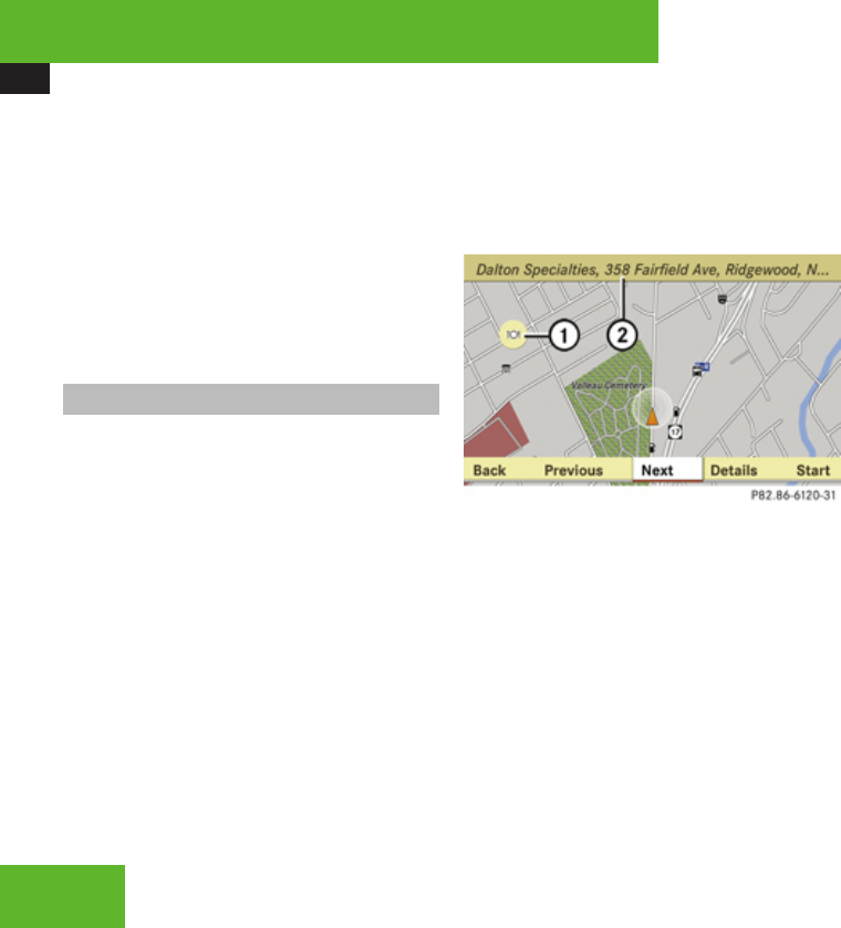
COMAND navigation system (Point of interest entry)
138
XExpanding list: In one of the lists select
Options £ Expand Search.
The list is expanded.
Options only in POI lists
XDisplaying details of the selected
entry: Select Options £ Details.
The detailed view appears.
XClosing detailed view: Select OK.
Entering a POI from the map
iIf the cross hair is shown on the map, you
can enter POIs in the vicinity of the cross
hair. If the cross hair is not shown on the
map, you can enter POIs in the vicinity of
the vehicle’s current position.
XSelect Guide in the map view with the
menu system displayed (Y page 107).
You will see POI symbols on the map,
depending on whether POIs are available
and which map scale is set.
The scale at which the symbols are
displayed on the map varies according to
the symbol.
You can set which symbols COMAND
should display (Y page 109).
The POI closest to the center of the screen
is automatically marked.
If there are no POIs available, the Back
menu item is automatically highlighted and
you cannot select other menu items.
1Highlighted POI
2Information about the highlighted POI
XSelecting a POI: Select Next or
Previous.
The next or the previous POI is marked.
XDisplaying details of the selection:
Select Details.
XStarting route calculation: Select
Start, see also (Y page 127).
A prompt appears asking whether the POI
should be used as the destination.
XSelect Yes or No.
If you select Yes, the route calculation
begins. If you select No, you can select a
new POI.
Control systems
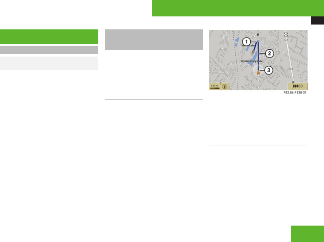
COMAND navigation system (route guidance)
139
COMAND navigation system (route
guidance)
Route guidance
GObserve Safety notes, see
page 99.
COMAND guides you to the destination using
navigation commands in the form of audible
navigation announcements and route
guidance displays.
iThe route guidance displays can only be
seen if the display is switched to navigation
mode.
If, for any reason, you do not follow the
navigation commands or if you leave the
calculated route, COMAND automatically
calculates a new route to the destination.
If the map data contains the relevant
information, COMAND tries to avoid roads
that only have limited access, e. g. roads
closed to through-traffic and non-residents.
Roads that have time restrictions (e. g. closed
on Sundays and public holidays) are not
considered for route guidance, if the digital
map contains the relevant information.
Examples of displays and
announcements for a driving
maneuver
Driving maneuvers have three phases:
RPreparation phase
RAnnouncement phase
RManeuver phase
Preparation phase
COMAND prepares you for the upcoming
driving maneuver. Based on the example
display below, the driving maneuver is
announced with the Prepare to turn
left message. The display is not split and
shows the map over the full screen.
1Point at which the driving maneuver takes
place (light blue dot)
2Route (highlighted blue)
3Current vehicle position; the triangle
points in the vehicle’s direction of travel
Announcement phase
COMAND announces the next driving
maneuver. Based on the example display
below, the driving maneuver is announced
700 feet in advance with the Turn left in
700 feet to your destination message.
The display is divided in two. In the left half,
you see the normal map view. In the right half,
there is either an enlarged view of the area
surrounding the intersection (intersection
zoom) or simply a symbol for the next driving
maneuver.
Control systems
Z
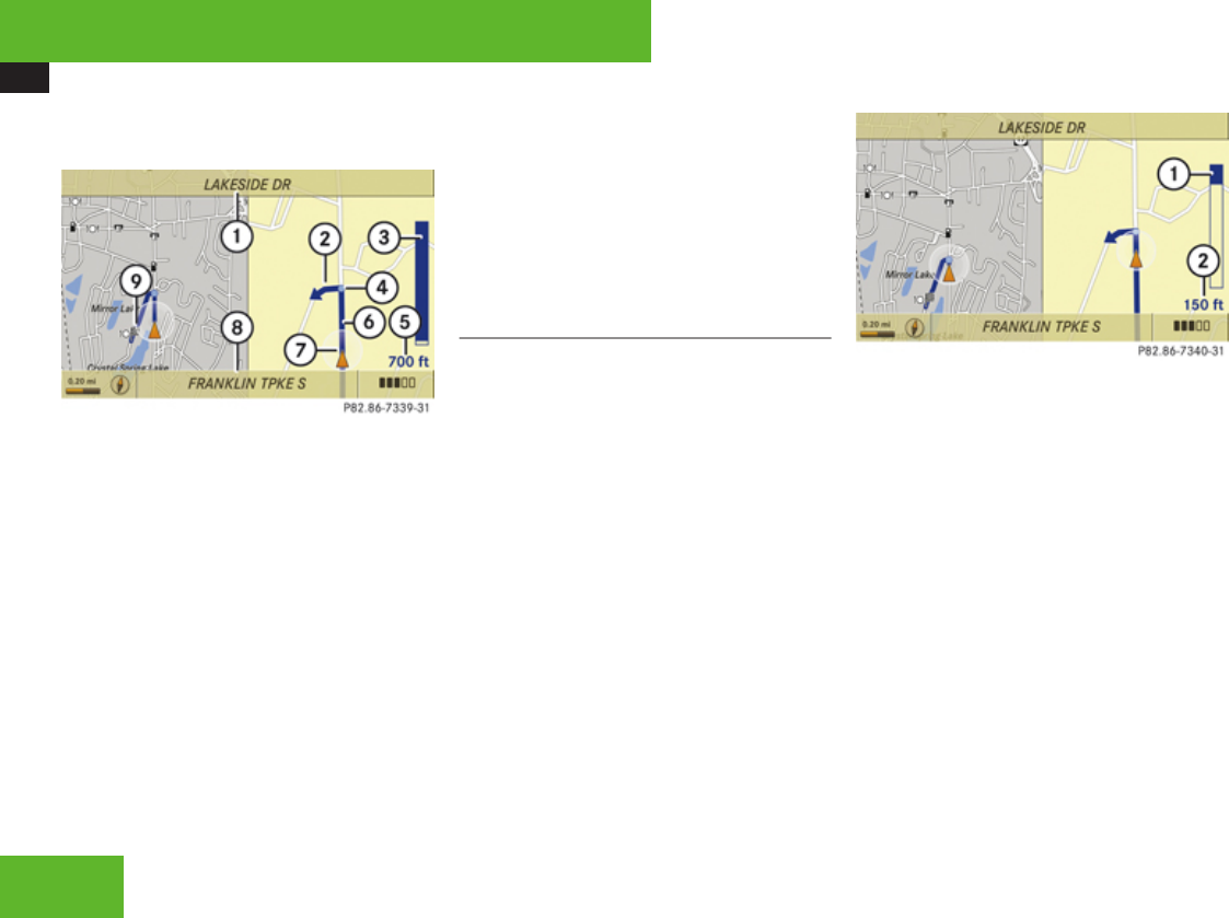
COMAND navigation system (route guidance)
140
The following example illustration shows the
intersection zoom in the right half.
1Next road
2Driving maneuver (turn left)
3Graphical representation of the distance
to the driving maneuver
4Point at which the driving maneuver takes
place (light blue dot, shown in both the left
and right displays)
5Information about distance to the next
driving maneuver
6Route (highlighted in blue; shown in both
the left and right displays)
7Current vehicle position; the triangle
indicates the vehicle’s direction of travel
(shown in both the left and right displays)
8Street on which you are currently driving,
if included on the digital map
9Destination
iThe filled-in section of distance graphic
3 gets shorter the nearer you get to the
announced driving maneuver.
Maneuver phase
COMAND announces the next driving
maneuver. Based on the example display
below, the driving maneuver is announced
150 feet in advance with the Now turn
left message. The display is also split into
two halves, as for the announcement phase.
iOnce the maneuver is completed,
COMAND automatically switches back to
the non-split screen.
1Graphical representation of the distance
to the next driving maneuver
2Information about distance to the next
driving maneuver
Control systems
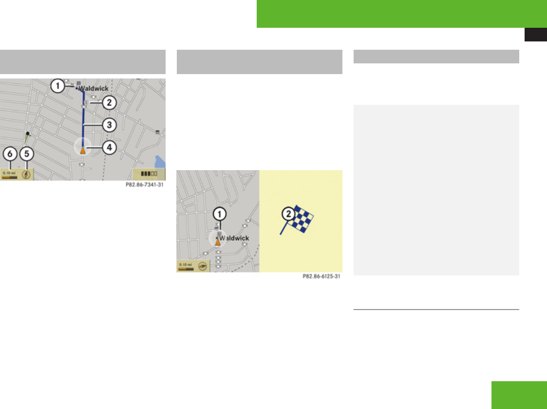
COMAND navigation system (route guidance)
141
Example of a display without driving
maneuvers
1Main destination <
2Stopover = (only visible if a stopover has
been entered)
3Route (highlighted blue)
4Current vehicle position; the triangle
indicates the vehicle’s direction of travel
5Set map orientation – for an explanation
and settings, see (Y page 109)
6Set scale – for an explanation and
settings, see (Y page 107)
Destination or destination area
reached
Once you have reached your destination, you
will hear the announcement You have
reached the destination. For certain
POIs (airports or highway junctions), you will
hear the announcement You have reached
the destination area. In addition, you will
see a corresponding display and route
guidance is automatically ended.
1Destination on the map
2Destination flag
Partially digitized areas
iThe digital map may contain areas that
are only partially digitized although they are
within a digitized region.
GWarning!
Due to incomplete digitization, the route
shown on the map may differ from the
actual road/traffic situation.
If you follow the route shown on the map,
for example, it is possible that you could
drive the wrong way down a one-way street
or that a street cannot be driven on.
When using route guidance in a partially
digitized area, you must therefore be sure
to observe all relevant traffic regulations
and the course of the road.
All relevant traffic regulations and the
course of the road always take priority over
the route shown on the map.
If the destination is within a partially
digitized area
COMAND guides you through fully digitized
areas for as long as possible. Route guidance
is conducted in the usual manner, i. e. with
navigation announcements and route
guidance displays.
Control systems
Z

COMAND navigation system (route guidance)
142
Before the vehicle reaches a partially digitized
area, COMAND notifies you of this with the
following announcements:
RBe prepared to enter an area where
turn by turn guidance cannot be
provided.
RIn 700 feet you will enter an area
where turn by turn guidance cannot
be provided.
iThe indicated distance can be seen here
by way of example. In reality, it may be
different.
RYou are about to enter an area
where turn by turn guidance cannot
be provided.
iWhen you call up the route info to this
type of destination, (Y page 145) the
following data shown there may differ from
the actual situation:
RDistance to the destination
REstimated driving time to the destination
REstimated arrival time
Route guidance within a partially
digitized area
If you start route guidance in this type of area,
you will hear the following announcement:
You are currently in an area where
turn by turn guidance cannot be
provided.
Route guidance is provided by means of a
direction arrow showing the compass
heading to the destination. COMAND will not
generate automatic navigation
announcements.
If you try to call up an announcement
manually, (Y page 144) you will hear the
announcement You are currently in an
area where turn by turn guidance
cannot be provided.
During route guidance, the display is divided.
On the right-hand side you will see the
direction arrow showing the compass
heading to the destination.
On the left-hand side of the display you will
see the map with the suggested route. The
suggested route is highlighted blue. However,
it may not be possible to follow the suggested
route because, for example, the road is
closed or not open for car traffic.
If, during route guidance, COMAND leads you
back into a fully digitalized area, route
guidance will simply continue in the usual
manner.
Off-road and off-map
Route guidance to an off-road
destination
GWarning!
The COMAND navigation system may
direct you to off-road routes that your
vehicle may not be capable of traversing
through without damaging your tires,
wheels or vehicle. It is the driver’s sole
responsibility to determine the suitability of
the route. Off-road routes may be of varying
conditions and their appropriateness for
use may be affected by various factors such
as time of day, time of year and immediate
weather conditions that cannot be judged
or taken into consideration by the
COMAND system.
COMAND can guide you to destinations
within the area covered by the digital map,
even if a destination is not located at a road
known to the system.
These destinations are shown as off-road
destinations, which you can enter using the
map, for example. In these cases, COMAND
Control systems
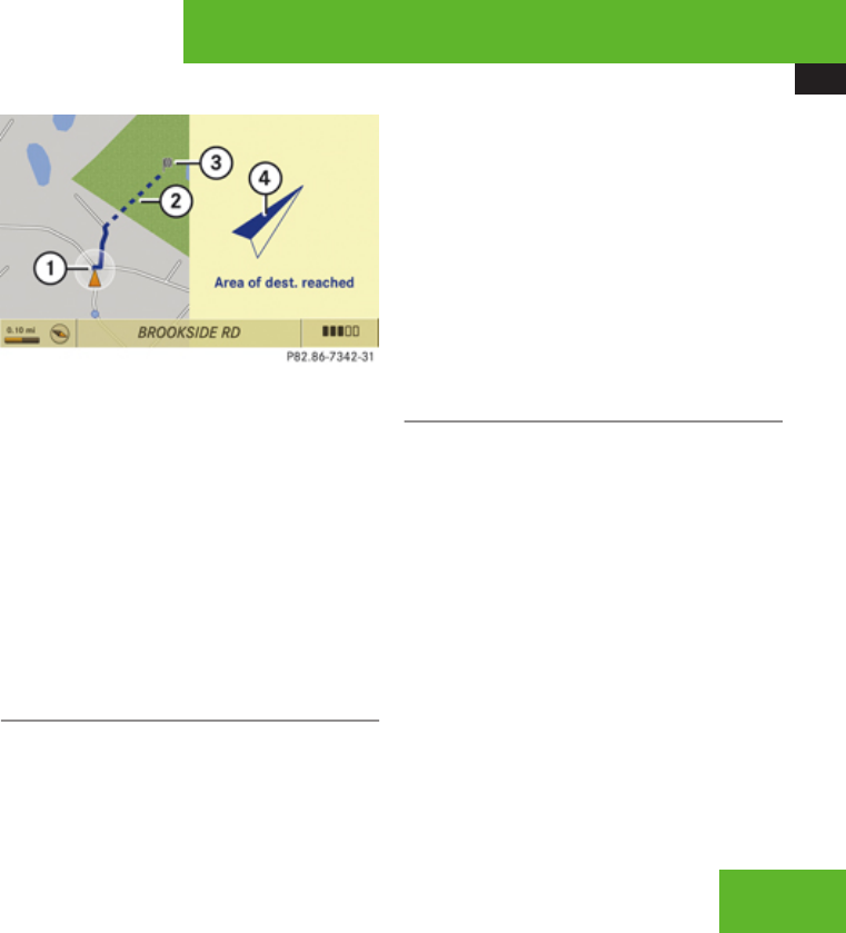
COMAND navigation system (route guidance)
143
guides you for as long as possible with
navigation announcements and displays on
roads known to the system.
Shortly before you reach the last known the
point to leave the digitized road network, you
will hear the announcement The
destination is nearby. Follow the
arrow on the display.
You will then see an arrow that indicates the
direction to the off-road destination. When
the off-road destination is close to the road,
Area of dest. reached appears in addition
below the arrow.
The section of the route from the last known
point on the map to the off-road destination
is indicated with a dashed line after a certain
length. It simply shows the direction to the
off-road destination without taking account of
any type of obstacles in the way.
1Current vehicle position; the triangle
indicates the vehicle’s direction of travel
2Off-road section of the route
3Off-road destination
4Direction arrow, shows compass heading
to destination
On the off-road section of the route, direction
arrows showing the compass heading to the
destination guide you. You will also see the
Direction to destination display.
Route guidance from an off-road
location to a destination
If there is no road available on map at current
position of the car, vehicle is off road.
COMAND is also able to guide you to a
destination from such a location.
At the start of the route guidance, you will see
the Off Road message and a direction arrow.
The direction arrow shows the compass
heading to the actual destination.
The route is highlighted blue from the nearest
road known to the system.
As soon as the vehicle is back on a road
known to the system, route guidance
continues in the usual way.
Route guidance from an off-map
location to a destination
If the vehicle position is outside the area
covered by the digital map, then the vehicle
is in an off-map location.
COMAND is also able to guide you to a
destination from such a location.
At the start of the route guidance, you will see
the Off Map message and a direction arrow.
The direction arrow shows the compass
heading to the actual destination.
The route is highlighted blue from the nearest
road known to the system.
As soon as the vehicle is back on a road
known to the system, route guidance
continues in the usual way.
Control systems
Z

COMAND navigation system (route guidance)
144
Off-road during route guidance
The road layout may differ from the data on
the digital map, due to road construction
measures, for example.
In such cases, the system cannot allocate the
vehicle position to the digital map and the
vehicle is therefore in an off-road position.
The Off Road message and an arrow showing
the compass heading to the destination
appear on the display.
As soon as the system can allocate the
vehicle position to the map again, route
guidance continues in the usual way.
Navigation announcements
GWarning!
Navigation announcements are intended to
direct you while driving without diverting
your attention from the road and driving.
Please always use this feature instead of
consulting the map display for directions.
Consulting the symbols or map display for
directions may cause you to divert your
attention from driving and increase your
risk of an accident.
iIf Russian or Chinese is set as the system
language, the navigation announcements
are in English. You will find how to set the
system language on (Y page 98).
Navigation announcements are muted
during telephone calls. You can, however,
call up a current announcement at any
time. You can also call up a current
announcement at any time if you have
missed an announcement.
Route guidance is already active.
XCalling up a current announcement:
Select Navi £ RPT.
or
XPress P favorite button if the button has
been programmed with this function
(Y page 98).
XSwitching off navigation messages:
Press F during an announcement.
You will see the message The driving
instructions have been muted. for a
short while.
iThe announcements remain switched off
even if you start a new route guidance or if
COMAND is switched off/on with the
o button.
If you switch COMAND off by removing the
SmartKey from the starter switch and then
switch the ignition back on after more than
3 minutes, the announcements are
automatically switched back on.
XSwitching navigation announcements
back on manually: Select Navi £ RPT.
XAdjusting volume of the messages:
Adjust the volume during an automatic
announcement (Y page 92).
or
XCall up an announcement manually using
Navi £ RPT and adjust the volume
(Y page 92).
Control systems
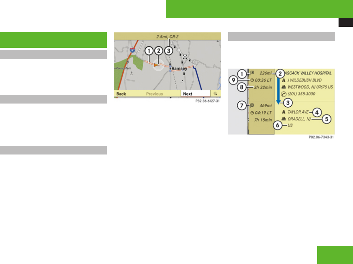
COMAND navigation system (during route guidance)
145
COMAND navigation system (during
route guidance)
Cancel route guidance
XSelect Destination £ Cancel Route
Guidance in map view with the menu
system displayed (Y page 107).
Continuing canceled route guidance
XSelect Destination £ Continue Route
Guidance in map view with the menu
system displayed (Y page 107).
COMAND calculates the route.
Route browser
iThe route browser shows an overview of
the route. You can use the route browser
to move along the route section by section
and view information about and details of
each section of the route.
XSelect Route £ Route Browser in map
view with the menu system displayed
(Y page 107).
The route browser appears.
1Highlighted route section
2Current vehicle position; the triangle
indicates the vehicle’s direction of travel
3Information about the highlighted route
section
iInformation 3 about the marked route
section shows the street name and the
length of the route section. Marked route
section 1 is always highlighted in white
and outlined in red.
XDisplaying next or previous route
section: Select Next or Previous.
XIncreasing or reducing size of the map:
Select ; or :.
XClosing route browser: Select Back.
Displaying info
XSelect Info in map view with the menu
system displayed (Y page 107).
The route information appears.
Example illustration: Display with main destination
and stopover
1Symbol = for stopover
2Distance to the destination
3Sequence of destinations (appears with at
least one stopover)
4Street
5City and abbreviation for province
(Canada) or state (USA)
6Country
7Symbol < for main destination
8Estimated driving time to the destination
9Estimated arrival time
Control systems
Z
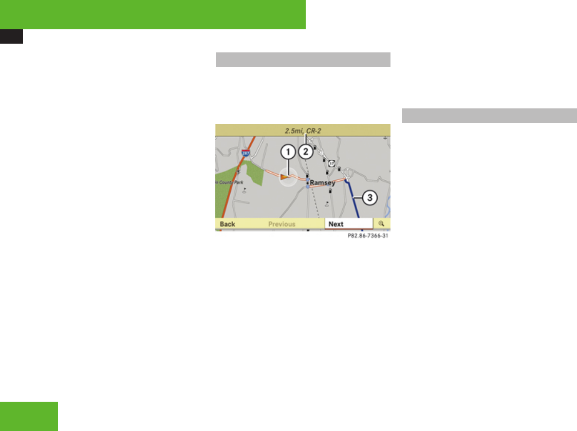
COMAND navigation system (during route guidance)
146
iCOMAND uses the time set in COMAND
as the basis for calculating the estimated
arrival time. The clock must be set correctly
in COMAND (Y page 96). The calculation of
the estimated arrival time does not
additionally take into account whether
Daylight Saving Time or standard time is
applicable at the destination. If the
destination is in a different time zone,
arrival time display 9 is in local time. This
is indicated by LT in the display.
The following data cannot be seen until the
route calculation has been completed:
RDistance to destination 2
REstimated arrival time 9
REstimated remaining travel time 8
If the destination is located within a
partially digitized area, the following data
may differ from the facts:
RDistance to destination 2
REstimated arrival time 9
REstimated remaining travel time 8
Displaying route information
XSelect Route £ Route Info in map view
with the menu system displayed
(Y page 107).
The route information appears.
1Highlighted portion of route
2Info for highlighted portion of route
3Next portion of route
XClosing route info: Slide omp or press
back button L in the center console
(Y page 90).
XDisplaying next or previous route
section: Select Next or Previous.
XIncreasing or reducing size of the map:
Select ; or :.
XClosing route browser: Select Back.
Detour function
iThe detour function blocks a section of
the route ahead of you. You can set the
length of the blockage. If possible,
COMAND calculates a detour route.
iThe detour function may direct you to off-
road routes. See Off-road and Off-map for
additional routes and cautions
(Y page 142).
XSelect Route £ Detour in map view with
the menu system displayed (Y page 107).
The detour function display appears.
XSetting length of the blockage: Select
More or Less until the desired length is set.
Control systems
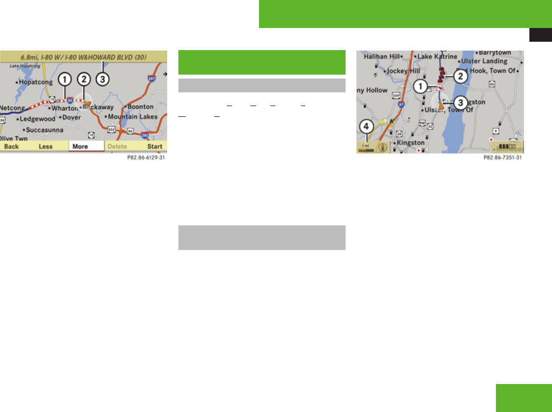
COMAND navigation system (real-time traffic)
147
1Blocked route section
2Current vehicle position; the triangle
indicates the vehicle’s direction of travel
3Information about the blocked route
section
iBlocked route section 1 is always
highlighted in red/white. The information
about blocked route section 3 shows
which section of the route is blocked and
the length of the blocked section.
XStarting route calculation: Select
Start, see also (Y page 127).
XDeleting blockage: Select Navi £
Route £ Detour £ Delete.
XSelect Back.
COMAND navigation system (real-
time traffic)
Introduction
A RDS-TMC (Radio Data System-Traffic
Message Channel) radio transmitter
broadcasts traffic reports COMAND can
receive and incorporate into the navigation
system. Traffic report messages and map
symbols can then be viewed in the COMAND
display. Events displayed are those within
receivable range of the vehicle’s location.
iActual road and traffic conditions may be
different from the received messages.
Real-time traffic notifications in the
map
COMAND can display certain traffic events in
the map. The notifications are shown at the
map scales from 0.05 mi (50 m) to 500 mi
(500 km).
XSet the map scale: Turn ymz until the
desired map scale is set.
Turning clockwise enlarges the map,
turning counterclockwise reduces it.
Example illustration: Display for a traffic jam on the
route
1Symbol for event on the route
2Marker symbols for the affected route
section
3Current vehicle position and direction of
travel
4Map scale
iCOMAND marks the entire route section
affected with appropriate symbols 2,
independently of its actual length on the
route section. Symbols 2 are shown in the
direction of travel on the left or right of the
route.Thus, they also indicate which side of
the roadway is affected by the event.
Control systems
Z
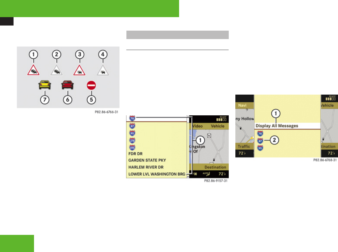
COMAND navigation system (real-time traffic)
148
The following shows the possible symbol
displays.
1Traffic jam on the route (symbol with red
border)
2Traffic jam away from the route (symbol
with gray border)
3Stop-and-go traffic on the route (symbol
with red border)
4Stop-and-go traffic away from the route
(symbol with gray border)
5Blocked section on the route
6Traffic jam
7Stop-and-go traffic
Displaying real-time traffic reports
Displaying the message list
XSelect Navi £ TMC.
COMAND searches for real-time traffic
transmitters. When no traffic reports are
present, you will see a display to this effect.
List for inactive route guidance
When route guidance is inactive, the list
displays all streets for which messages are
present.
1Affected street list
iInstead of a street, an area or a region can
also be affected by a message, for example,
when visibility is limited due to fog.
XRead a message: Select a street.
You can find an example message on
(Y page 149).
XClose the list: Slide omp.
List for active route guidance
When route guidance is active, the list
displays only the streets which are part of the
route and for which messages are present.
1Show all messages (including those which
do not affect the route)
2Affected streets (only shown when
messages which affect the route are
present)
Control systems
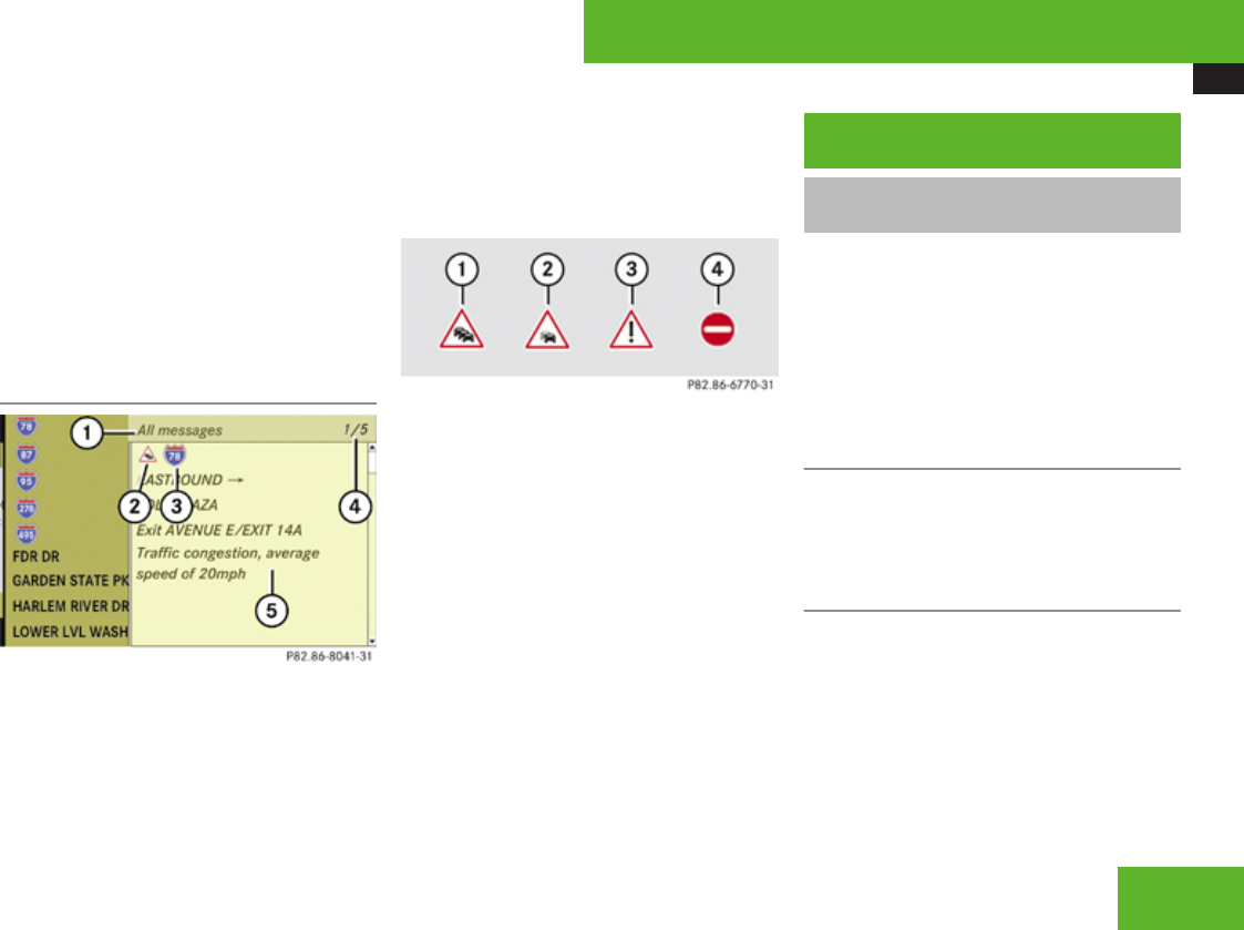
COMAND navigation system (destination memory)
149
XDisplay all messages: Select Display
All Messages.
All streets are shown for which messages
are present, as well as for those which are
not on the route.
XRead a message: Select a street.
You can find an example message below.
XClose the list: Slide omp once or
repeatedly.
Example message
1Selection display (Messages On Route or
All messages)
2Symbol for message event (e. g. traffic
jam)
3Street affected by the message
4Message 1 of 5 for the affected street
5Message text
The symbols for the possible message events
are shown in the following.
1Traffic jam symbol
2Stop-and-go traffic symbol
3Warning message symbol
4Blocked section symbol
XScroll through the contents or to the
next message: Turn ymz or slide qmr.
COMAND navigation system
(destination memory)
Saving a destination in the
destination memory
iThis function also saves the destination in
the address book. There COMAND creates
an address book entry containing
complete, navigable address data. You can
then select this entry in the address book
and start navigation to the address.
Saving after the address has been
entered
XSelect “Save” after entering the address
(Y page 112).
You can now select save options.
Saving during route guidance
XSelect Destination £ Save
Destination during route guidance.
You can now select save options.
Control systems
Z
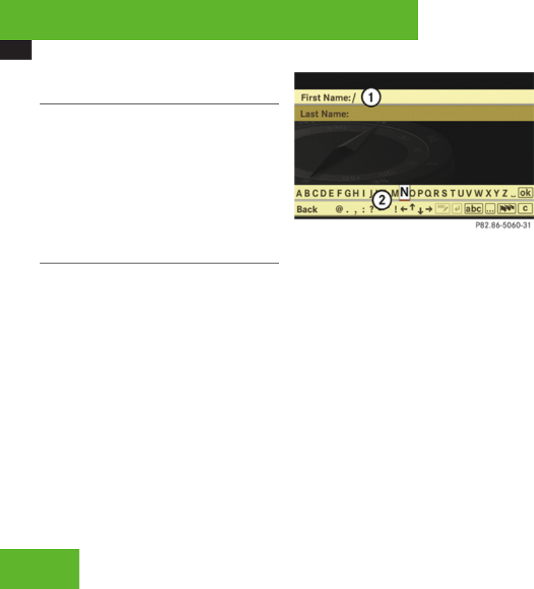
COMAND navigation system (destination memory)
150
Saving a destination from the list of last
destinations
XSelect Navi £ Destination £ From
Last Destinations.
The list of last destinations appears.
XSelect desired destination.
The address of the destination is displayed.
XSelect Save.
You can now select save options.
Selecting save options
Saving a destination without a name
XSelect Save Without Name.
COMAND saves the destination in the
destination memory and uses the address
as the destination name.
or
XSelect Save as ‘My Address’.
XSelect desired category, e. g. Home.
COMAND saves the destination in the
destination memory as your own address.
Saving a destination with a name
XSelect Save new entry.
XSelect desired category, e. g. Home.
The input menu appears with the data fields
and the input characters.
1Selected data field with input mark
(cursor)
2Input characters
XEntering data: Proceed as described in the
“Changing the data field” operating step in
the “Creating a new address book entry”
section (Y page 175).
Assigning a destination to an address
book entry
iThis function assigns the complete,
navigable address data to an already
existing address book entry. You can then
select this entry in the address book and
start navigation to the address from there.
XSelect Assign Address Book Entry.
XSelect desired category, e. g. Home.
The menu appears for searching for an
address book entry.
XSelect desired address book entry.
Proceed as described in the “Searching for
an address book entry” section
(Y page 176).
If the selected address book entry does not
yet contain any navigable address data,
COMAND saves the data.
If the selected address book entry already
contains navigable address data, you will
see a question asking you if the previous
data should be overwritten.
XSelect Yes or No.
If you select Yes, COMAND saves the data.
Control systems
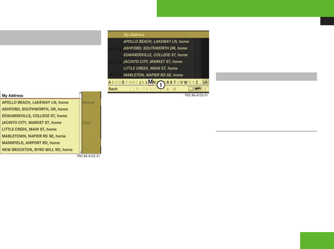
COMAND navigation system (destination memory)
151
Deleting a destination from the
destination memory
XSelect Navi £ Destination £ From
Memory.
Depending on the number of entries in the
destination memory, you will see the
destination memory list with or without
input characters.
Example illustration: Destination memory list
without input characters
Example illustration: Destination memory list with
input characters
1Input characters
XSelect desired destination. Proceed as
described for destination entry in the
“Entering a destination from the
destination memory” section
(Y page 128).
XSelect Delete after selecting the
destination to be deleted.
A prompt appears asking whether you want
to delete the destination.
XSelect Yes or No.
If you select Yes, COMAND deletes the
destination.
iIf the navigable address data of the
destination to be deleted has also been
assigned to an address book entry,
COMAND deletes the data there as well. If
the corresponding address book entry
does not contain any further data, such as
telephone numbers, COMAND deletes the
entire address book entry.
Own address
iThe destination memory always contains
an entry called My Address. You can save
your home address, for example, under this
entry.
Assigning your address for the first
time or changing your own address
Assigning and/or changing your own
address
XSelect Navi £ Destination £ From
Memory.
Depending on the number of entries in the
destination memory, you will see the
destination memory list with or without
input characters.
Control systems
Z
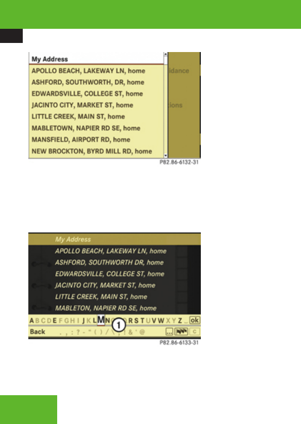
COMAND navigation system (destination memory)
152
Example illustration: Destination memory list
without input characters
In the destination memory list without input
characters, the My Address entry is
automatically highlighted.
Example illustration: Destination memory list with
input characters
1Input characters
In the destination memory list with input
characters 1, the input characters are
automatically activated.
XDestination memory list without input
characters: Press n immediately.
or
XDestination memory list with input
characters: Slide qm repeatedly until the
input characters disappear.
The list entry My Address is automatically
highlighted as long as you have not entered
any characters using the input characters.
If you have entered characters from the
list of input characters: Rotate ymz or
slide qm repeatedly until the list entry My
Address is highlighted.
XPress n.
Further operation depends on whether you
want to enter the address manually or use an
address book entry as your own address.
Entering an address manually
XIf you want to assign your own address
for the first time: Select Save new
entry.
or
XIf you want to change your own
address: Select Change £ Save new
entry.
In both cases, the address input menu
appears.
XEnter the address. Proceed as described
for destination entry in the “Entering a
destination by address” section
(Y page 112).
XSelect Save after entering the address.
Your address is saved.
Using the address book entry as your own
address
XIf you want to assign your own address
for the first time: Select Assign Address
Book Entry.
or
XIf you want to change your own
address: Select Change £ Assign
Address Book Entry.
In both cases, the menu appears for
searching for an address book entry.
Control systems
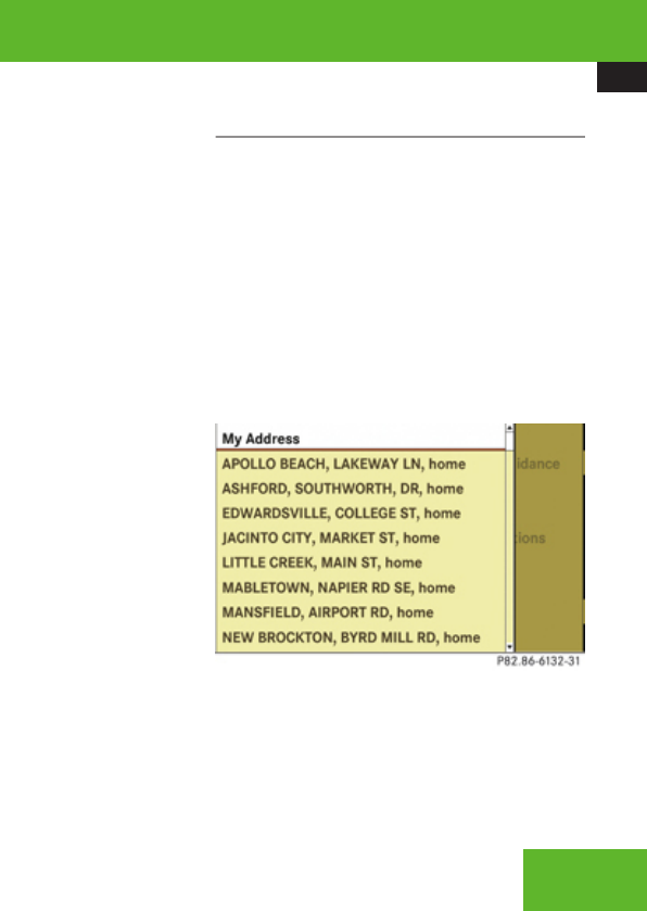
COMAND navigation system (destination memory)
153
XSelect desired address book entry.
Proceed as described in the “Searching for
an address book entry” section
(Y page 176).
Once the address data is complete and if it
matches the digital map data, COMAND
saves the entry as your own address in the
destination memory.
If address data is still missing or if it cannot
be found on the digital map, a message
appears indicating that the address is
incomplete.
XClosing message: Select OK.
iIn the address book entry, the city and
street must be spelled in the same way as
the destination entry so that the data
matches the digital map data.
In order for the state (USA) or province
(Canada) to match the map data, you may
either enter the entire name or the
abbreviation in the address book.
Examples:
RFlorida or FL
RColorado or CO
RAlberta or AB
ROntario or ON
Depending on which data is missing or cannot
be found on the digital map, you must now
either:
Rselect a state (USA) or province (Canada)
Ror enter a city
Ror enter a street
Ror enter a house number
XSelecting a state (USA) or province
(Canada): Select desired state (USA) or
province (Canada) from the list.
XEntering a city: Proceed as described for
destination entry in the “Entering a city”
section (Y page 116).
XEntering a street: Proceed as described
for destination entry in the “Entering a
street” section (Y page 119).
XEntering a house number: Proceed as
described for destination entry in the
“Entering a house number” section
(Y page 123).
If all data is available and matches the
digital map data, you can save the address.
XSaving: Select Save.
Displaying your own address
XSelect Navi £ Destination £ From
Memory.
The destination memory list appears either
with or without the input characters.
Whether the input characters appear
depends on the number of entries in the
destination memory.
XPress n.
Destination memory list without input
characters
In the destination memory list without input
characters, the My Address entry is
automatically highlighted.
Control systems
Z

COMAND navigation system (last destinations)
154
XPress n.
If your own address has already been
assigned, you will see the menu for starting
route guidance with your own address data.
XExiting menu: Select Back.
Destination memory list with input
characters
1Input characters
In the destination memory list with input
characters 1, the input characters are
automatically activated.
XSlide qm repeatedly until the input
characters disappear.
The list entry My Address is automatically
highlighted as long as you have not entered
any characters using the input characters.
If you have entered characters from the
list of input characters: Rotate ymz or
slide qm repeatedly until the list entry My
Address is highlighted.
XPress n.
If your own address has already been
assigned, you will see the menu for starting
route guidance with your own address data.
XExiting menu: Select Back.
COMAND navigation system (last
destinations)
iCOMAND automatically saves the last
destinations for which the route calculation
was launched. It is stored in the “last
destinations” memory. If this memory is
full, COMAND deletes the oldest
destination. You can also save one
destination from the list of last destinations
in the destination memory. It will be saved
there permanently.
Saving a destination permanently in
the destination memory
XProceed as described in the “Saving a
destination from the list of last
destinations” section (Y page 150).
Control systems

COMAND telephone
155
Saving the vehicle position in the list
of last destinations
XCentering map on the vehicle’s
position: Select Navi £ Position £
Vehicle Position Map.
XSaving: Select Navi £ Position £
Save Position.
COMAND saves the current vehicle
position as a destination in the list of last
destinations.
Saving the cross hair position in the
list of last destinations
iIf you have manually moved the map, you
will see a cross hair on the map
(Y page 107). You can save the cross hair
position as a destination in the list of last
destinations.
XShowing menu system, if necessary:
Press n.
XSelect Position £ Save Position.
COMAND saves the cross hair position as
a destination in the list of last destinations.
Deleting one of the last destinations
XSelect Navi £ Destination £ From
Last Destinations.
The list of last destinations appears.
XSelect desired destination.
The address of the destination appears.
XSelect Delete.
XSelect Yes or No.
COMAND telephone
Safety notes
GWarning!
Some jurisdictions prohibit the driver from
using a cellular telephone while driving.
Whether or not prohibited by law, for safety
reasons, the driver should not use the
cellular telephone while the vehicle is in
motion. Stop the vehicle in a safe location
before placing or answering a call.
If you nonetheless choose to use the mobile
phone4 while driving, please use the
handsfree feature and be sure to pay
attention to the traffic situation at all times.
Use the mobile phone only when road,
weather and traffic conditions permit.
Otherwise, you may not be able to observe
traffic conditions and could endanger
yourself and others.
Bear in mind that at a speed of just 30 mph
(approximately 50 km/h), your vehicle is
covering a distance of 44 feet
(approximately 14 m) every second.
GWarning!
Never operate radio transmitters equipped
with a built-in or attached antenna (i.e.
4Observe all legal requirements
Control systems
Z

COMAND telephone
156
without being connected to an external
antenna) from inside the vehicle while the
engine is running. Doing so could lead to a
malfunction of the vehicle’s electronic
system, possibly resulting in an accident
and/or serious personal injury.
General notes
iUSA only:
This device complies with Part 15 of the
FCC Rules. Operation is subject to the
following two conditions:
1. This device may not cause harmful
interference, and
2. this device must accept any
interference received, including
interference that may cause undesired
operation.
Any unauthorized modification to this
device could void the user’s authority to
operate the equipment.
iCanada only:
This device complies with RSS-210 of
Industry Canada. Operation is subject to
the following two conditions:
1. This device may not cause interference,
and
2. this device must accept any
interference received, including
interference that may cause undesired
operation of the device.
Any unauthorized modification to this
device could void the user’s authority to
operate the equipment.
Calls disconnected while the vehicle is
in motion
A call may be disconnected if:
Rthere is insufficient network coverage
Ryou move from one transmitter/receiver
area (cell) into another and no channels are
free or the cell is full
Operating options
iThe components and operating principles
of COMAND can be found on (Y page 82).
iVarious mobile phone cradles can be
installed in the front center armrest, see
separate installation instructions for the
mobile phone cradle. These mobile phone
cradles can be obtained from an authorized
Mercedes-Benz Center. For more
information about telephone
(Y page 424) and (Y page 248).
When the mobile phone is inserted in the
cradle, you can operate the telephone using
the following devices:
Rmobile phone keypad
RCOMAND telephone keypad
Rbuttons s and t on the
multifunction steering wheel
(Y page 237)
RVoice Control (Y page 265)
RBluetooth® headset (Y page 168)
Please note that these functions are only
available with Mercedes-Benz approved
mobile phones. Please contact an authorized
Mercedes-Benz Center for information on
features available for your mobile phone of
choice.
You can control other functions of the mobile
phone via the COMAND, instrument cluster
Control systems

COMAND telephone
157
control system (Y page 248) or Voice
Control.
iIn order for the functions described in this
section to work correctly, the Bluetooth®
headset must be linked to COMAND
(Y page 184). Please make sure any
Bluetooth® headset linked with the mobile
phone is switched off or that the headset is
linked with COMAND before you insert the
mobile phone in the cradle, see separate
installation instructions for the cradle, and
use the telephone functions with
COMAND.
The descriptions in this section assume that
the mobile phone is inserted in the cradle.
Exceptions to this are clearly stated.
Unless otherwise indicated, the descriptions
and illustrations in this section refer to
COMAND and the telephone keypad.
Operation using the mobile phone and
Bluetooth® headset is described in the
respective separate Operating Instructions.
Caller ID
COMAND can display the telephone number
and the name of the caller, e. g. for an
incoming call and also in other menus or
displays.
For the telephone number to be displayed,
the caller must transmit their telephone
number.
This is also the case for name displays. For
this, the telephone number and the name of
the caller must also be saved in the mobile
phone book.
Functional restrictions
You will not be able to use the telephone, or
you may have to wait a while, in the following
situations:
RIf the telephone has not yet logged into the
network.
The telephone automatically tries to log
into a network. If no network is available,
you will also not be able to make a “911”
emergency call. If you attempt to make an
outgoing call, the No Service message will
appear for a short while.
RIf the mobile phone is not inserted in the
cradle.
RSIM card is not inserted in GSM type phone.
iA roof cargo container may impair mobile
phone reception. In an emergency, remove
the mobile phone from the mobile phone
cradle, see separate installation
instructions for the cradle, to make a call.
Notes about COMAND telephone
features using a Bluetooth® connection
Many of the Mercedes-Benz approved mobile
phones, cradles and adaptors available for
use in your vehicle utilize Bluetooth®
technology to communicate with each other
and the vehicle. Depending on your phone
brand and model, the number of in-vehicle or
on-display COMAND telephone features
supported via Bluetooth® communication,
and thus available for your use, may vary.
The descriptions and illustrations in this
section are based on the use of fully
compatible Mercedes-Benz approved mobile
phones and cradles that do not utilize
Bluetooth® technology to communicate with
each other. If your vehicle is equipped with
integrated Bluetooth® functionality, a
Bluetooth® capable mobile phone, headset,
Laptop, PDA, etc. is required to utilize those
features.
For additional information about Mercedes-
Benz approved Bluetooth® mobile phones
and related accessories please contact the
Mercedes-Benz Customer Assistance Center
Control systems
Z
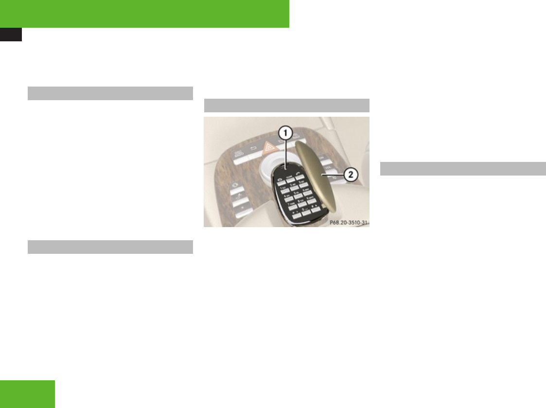
COMAND telephone
158
at 1-800-FOR-MERCedes or the nearest
authorized Mercedes-Benz Center.
Switching telephone on or off
XSwitching on: Insert mobile phone into
cradle when COMAND is switched on.
or
XSwitch on the mobile phone (see mobile
phone operating instructions).
XSwitching off: Select Telephone £
Telephone £ Telephone OFF.
or
XSwitch off mobile phone (see mobile phone
operating instructions).
Activating telephone mode
XSelect Telephone £ Telephone.
or
XPress s on telephone keypad.
or
XPress the N shortcut button once or
twice.
iThe number of times you have to press
the N shortcut button depends on the
operating mode currently selected.
Telephone keypad
1Telephone keypad
2Folding cover
With the telephone keypad you can:
REnter and clear numbers and special
characters.
RReject, accept, connect and end calls.
XEntering characters: Select Telephone.
XFold up cover 2.
XEnter characters using the A - #
buttons.
iYou can enter the * character by pressing
> once. Pressing this button again
within 1.5 seconds enters the + character.
XDeleting individual characters: Press
*.
XDeleting an entire word or number:
Press and hold * until the word or
number is deleted.
“911” emergency call
iThe “911” emergency call system is a
public service. Using it without due cause
is a criminal offense.
iThis function places a call to the local
“911” provider. It does not initiate a Tele
Aid call.
The following conditions must be fulfilled in
order to make a “911” emergency call:
RThe phone is switched on.
RA mobile network is available.
RThere is a valid SIM card in the phone (not
necessary in all mobile networks).
iIf no SIM card is inserted in the mobile
phone, you can only initiate a “911”
Control systems

COMAND telephone
159
emergency call by using COMAND and the
mobile phone.
If you cannot make an emergency call, you
must initiate rescue measures yourself. The
“911” emergency call is a public service. Any
misuse is punishable by law.
iA roof cargo container may impair mobile
phone reception. In an emergency, remove
the mobile phone from the mobile phone
cradle, see separate installation
instructions for the cradle, to make a call.
Placing a “911” emergency call before
entering PIN/PIN2, PUK/PUK2 or
unlock code
Entering the number using the COMAND
controller
XSelect Telephone £ Dial 911.
Entering the number using the telephone
keypad
XEnter digits 9-1-1 (Y page 158).
XPress s.
Placing a “911” emergency call after
entering PIN/PIN2, PUK/PUK2 or
unlock code
Entering the number using the COMAND
controller
XSelect Telephone.
XSelect all the digits in sequence.
XSelect 4.
Entering the number using the telephone
keypad
XEnter digits 9-1-1 (Y page 158).
XPress s.
Confirming the emergency call
After the digits have been entered, you will
see the question Do you want to dial the
911 emergency number?.
XUse COMAND controller to select Yes.
The telephone makes the connection.
XWait until the emergency call center
answers and describe the emergency
situation.
Entering the PIN
iYour PIN code (Personal Identification
Number code) prevents unauthorized
persons from using your GSM mobile
phone. The PIN code is a number string,
which you have to enter when switching on
the telephone.
The PIN entry applies only to GSM mobile
phones.
Entering using the COMAND controller
XSelect Telephone.
XEntering: Select all the digits in sequence.
XDeleting a digit: Select ) and briefly
press n.
XDeleting an entire number: Select ) and
press and hold n until the number is
deleted.
XConfirming an entry: Press n.
Entering using the telephone keypad
XEntering: Enter digits using the R -
9 buttons (Y page 158).
XConfirming an entry: Press n or press
s.
Control systems
Z

COMAND telephone
160
Entering the PIN2
iThe PIN2 entry applies only to GSM
mobile phones.
The phone may request the PIN2 in order to
use certain functions. A corresponding
message appears in the display.
XEnter PIN2 digits into mobile phone.
Entering the PUK/PUK2
iThe PUK/PUK2 entry (Personal
Unblocking Key) applies only to GSM
mobile phones.
If you enter the PIN or PIN2 incorrectly three
times, the SIM card will be locked. A
corresponding message appears in the
display. It is necessary to enter the PUK/
PUK2 to unlock it. The PUK and/or PUK2 are
provided by your telephone service provider.
XEnter PUK/PUK2 digits into mobile phone.
Entering the unlock code
Many mobile phones can be protected from
unauthorized use with an unlock code (see
mobile phone operating instructions). If you
wish to use the phone functions when the
unlock code is active, a screen appears
requesting that you enter the unlock code.
You cannot use the phone functions (except
“911” emergency call) until you have entered
the unlock code.
XProceed in the same way as entering the
PIN (Y page 159).
Telephone submenu overview
iThe components and operating principles
of COMAND can be found on (Y page 82).
Control systems

COMAND telephone
161
Name (only when
the mobile phone is
inserted in the
cradle)
Data/Connections Call lists (not during
a call)
Text message (not
during a call)
DTMF (only during a
call)
Mic OFF/ON (only
during a call)
Display COMAND
phone book
RAddress book
RBluetooth®
Display call list
selection:
RCalls received
RCalls dialed
Call up SMS inbox Send numerical
sequence
Switch hands-free
microphone on/off
Main telephone menu
XCalling up main menu: Select
Telephone.
or
XPress s on the telephone keypad
(Y page 158).
iIf you press s when the main
telephone menu has already been called
up, the Calls Dialed list will appear
(Y page 162). 1Numbers/characters to enter
telephone number
2Symbol ò for new voice message in
mailbox
3Symbol ð for unread SMS messages
in SMS inbox (Y page 186)
4Signal strength and network status
display
RNetwork status READY = mobile
phone is logged in with its own
provider’s network
RNetwork status READY ROAM =
mobile phone is logged in with
another provider’s network
RNetwork status No Service = No
network available
5To show COMAND phone book
(Name) (Y page 169)
Control systems
Z
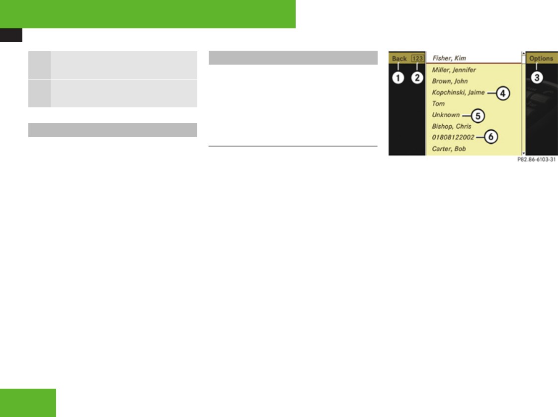
COMAND telephone
162
6To call up text message (SMS)
(Y page 186)
7To display call list selection
(Y page 162)
Mailbox
The symbol ò in the example illustration
above indicates that your mailbox contains
new voice messages. You will have to call the
mailbox in order to retrieve the messages.
You can call your mailbox by:
Rspeed dialing (Y page 166)
Rentering a telephone number using the
telephone keypad (Y page 165)
Rentering the telephone number using the
COMAND controller (Y page 165)
iOnce connection with your mailbox has
been established, the mailbox system will
guide you through the next steps.
Call lists
COMAND can display the following calls in
separate lists:
RCalls received
RCalls dialed
Calling up a list
XSelect Call Lists from main telephone
menu.
XSelect Calls Received or Calls
Dialed.
The corresponding list appears.
iThe Calls Received and Calls
Dialed menu items do not function if the
respective list has no entries. The Call
Lists menu item does not function if
neither list has any entries.
Example illustration: List of calls received
1To close list
2To switch list display (n or g)
3To call up options
4Name or telephone number of a caller
5Unknown caller
6Telephone number of a caller
iIn the list of calls received, you will see
the name of caller 4 if
Rthe caller transmitted the telephone
number
Rthe name and telephone number are
saved in the COMAND address book or
in the phone book on the mobile phone
Rthe telephone number is saved in the
same way in which the caller transmits it
Control systems

COMAND telephone
163
You will see the telephone number of caller
6 if
Rthe caller transmitted the telephone
number
Rno caller data is saved in either the
COMAND address book or the phone
book on the mobile phone
An unknown caller 5 has not transmitted
his or her telephone number.
iIn the list of dialed calls, you will see the
name of the person called if you have saved
his or her telephone number and name in
the COMAND address book or in the phone
book on the mobile phone. If no data has
been saved, you will see the telephone
number.
XSwitching to list display: Select n or
g.
The display changes to telephone number
or name display.
XClosing list: Slide omp and select Back.
XSelecting a list entry: Slide qmr or rotate
ymz and select entry.
Displaying details of a list entry
COMAND can also show a shortened list entry
in its entirety.
XSelect list entry (Y page 162).
XSlide omp and select Options £
Details.
The detailed view appears.
XClosing detailed view: Slide qmr or
omp or press n.
Saving a list entry in the address book
iList entries that show a telephone number
are neither saved in the COMAND address
book, nor in the phone book on the mobile
phone. You can save such entries in the
COMAND address book. You can also save
list entries in the COMAND address book
which have already been saved in the
phone book on the mobile phone.
Saving as a new entry in the COMAND
address book
XSlide omp or rotate ymz and select list
entry (Y page 162).
XSelect Options £ Save £ New Entry.
iSave does not function if the selected list
entry is already saved in the COMAND
address book.
XSelect a number category, e. g. Home.
XSelect a telephone category, e. g. Land
Line.
XSelect Save.
The input menu appears with the data
fields. The data field for the telephone
number is filled in automatically. The data
field for the last name is also filled in
automatically if the entry to be saved
contains a name.
XIf you would like to save the entry
now: Select d.
Control systems
Z
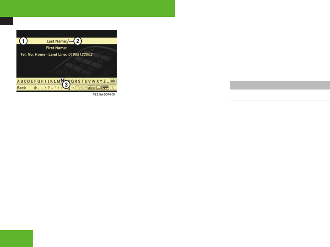
COMAND telephone
164
1Data field
2Input mark (cursor)
3Input characters
XIf you want to change the available
characters: Proceed as described in the
“Changing data field” paragraph in the
“Assigning a New Entry in the Address
Book” section (Y page 171).
Adding to an existing entry in the
COMAND address book
XSlide omp or rotate ymz and select list
entry (Y page 162).
XSelect Options £ Save £ Add.
iSave does not function if the selected list
entry is already saved in the COMAND
address book.
XSelect a number category to add, e. g.
Home.
XSelect a telephone category to add, e. g.
Land Line.
XSelect Save.
The search menu for COMAND address
book entries appears.
XSearch for desired entry.
iThere is a detailed description of
searching for an COMAND address book
entry in the “Searching for an address book
entry” section (Y page 176).
XPress n when you have finished searching.
COMAND saves the data if there are fewer
than four numbers assigned to the entry
you are searching for in the selected
number category.
If four numbers are saved for the entry you
are searching for, a prompt will appear
asking whether you want to overwrite one
of the existing numbers.
XSelect Yes or No.
If you select Yes, a selection list will appear
containing the four existing numbers.
XSelect the number to be overwritten.
COMAND overwrites the selected number
with the new data.
Incoming call
Rejecting or accepting the call
XRejecting: Select Reject.
or
XPress t on the telephone keypad or on
the multifunction steering wheel.
iIf you have a CDMA/TDMA mobile phone
and reject a call, only the ring tone will stop.
The call itself can only be ended by the
caller.
XAccepting: Select Accept.
or
XPress s on the telephone keypad or on
the multifunction steering wheel.
or
XPress 0 on the multifunction steering
wheel.
Control systems

COMAND telephone
165
XUse the mobile phone (see mobile phone
operating instructions).
or
XUse the Bluetooth® headset (see headset
operating instructions).
iThe use of a Bluetooth® headset requires
Bluetooth® to be activated and the
Bluetooth® headset to be authorized
(Y page 184).
If you have accepted the call using COMAND,
the telephone keypad, the multifunction
steering wheel or the mobile phone, the call
will be conducted via the hands-free system.
The volume of the call can be adjusted
(Y page 92).
If you have accepted the call using the
Bluetooth® headset, the call will be
conducted via the headset.
Further operating functions can be found in
the “Functions during a single-call
connection” section (Y page 167).
You can also accept a call if the COMAND
display is showing a screen other than the
telephone mode screen. After accepting the
call, you will see the caller’s data in a window.
XClosing window: Slide qmr or omp or
press n.
Making an outgoing call
iIf you place an outgoing call and receive
a busy signal, the telephone automatically
starts to redial as long as the provider and
the mobile phone support this function (see
mobile phone operating instructions).
While the call is connecting, you can also
send character strings (Y page 167).
Entering the telephone number using
the COMAND controller
XSwitching screen to telephone mode:
Call up main telephone menu
(Y page 161).
XEntering digits: Select desired digits by
rotating ymz or sliding omp and
press n.
XDeleting individual digits: Select ) and
briefly press n.
XDeleting an entire telephone number:
Select ) and press and hold n until the
telephone number is deleted.
XConnecting a call: Select S.
Entering a telephone number using the
telephone keypad
XSwitching screen to telephone mode:
Call up main telephone menu
(Y page 161).
XUse telephone keypad to enter digits.
iA detailed description of how to enter
digits using the telephone keypad can be
found on (Y page 158).
XConnecting a call: Press s.
Redial
XSwitching screen to telephone mode:
Call up main telephone menu
(Y page 161).
XUse COMAND controller to select S.
or
XPress s on the telephone keypad
(Y page 158).
The list of dialed numbers appears. The
most recently dialed number is at the top.
XSelect desired entry.
XConnecting a call: Press n.
iIf the list of dialed calls contains no
entries, the S menu item cannot be
Control systems
Z

COMAND telephone
166
selected and the s button on the
telephone keypad does not function.
Placing a call to a call list entry or
COMAND phone book entry
XCall up a call list and select an entry
(Y page 162).
or
XCall up COMAND phone book and select an
entry (Y page 169).
XConnecting a call: Press n.
Speed dialing
You can save telephone numbers in the
speed-dial preset locations on the mobile
phone and call up the speed-dial presets (see
mobile phone operating instructions).
iBy default, the mailbox number is preset
in the speed dial memory unless you have
modified it. For more information on the
mailbox (Y page 162).
You can also call up speed-dial numbers using
COMAND.
iOperation during call connection depends
on the speed-dial preset position called up.
Calling up speed-dial presets using the
COMAND controller
XSwitching screen to telephone mode:
Call up main telephone menu
(Y page 161).
XEntering number of a speed-dial
preset: Select all the digits in sequence.
Deleting individual digits: Select ) and
briefly press n.
Deleting entire number: Select ) and
press n until the number is deleted.
XConnecting a call (speed-dial presets
1 - 99): Select S.
or
XConnecting a call (speed-dial presets
100 - 999): Select # after the digits £
S.
In both cases, the telephone connects the
call to the saved telephone number. If the
speed-dial memory contains no telephone
numbers, you will see a corresponding
message.
XDeleting message: Press n.
Calling up speed-dial numbers using the
telephone keypad
XSwitching screen to telephone mode:
Call up main telephone menu
(Y page 161).
XSingle-digit numbers: Press and hold the
A - 9 buttons.
or
XSingle- and two-digit numbers: Enter
number using the A - 9 buttons.
XPress s.
or
XThree-digit numbers: Enter number using
the A - 9 buttons.
XPress #, and then s.
In all three cases, COMAND connects the
call to the saved telephone number. If the
speed-dial memory contains no telephone
numbers, you will see a corresponding
message.
XDeleting message: Press n.
Control systems
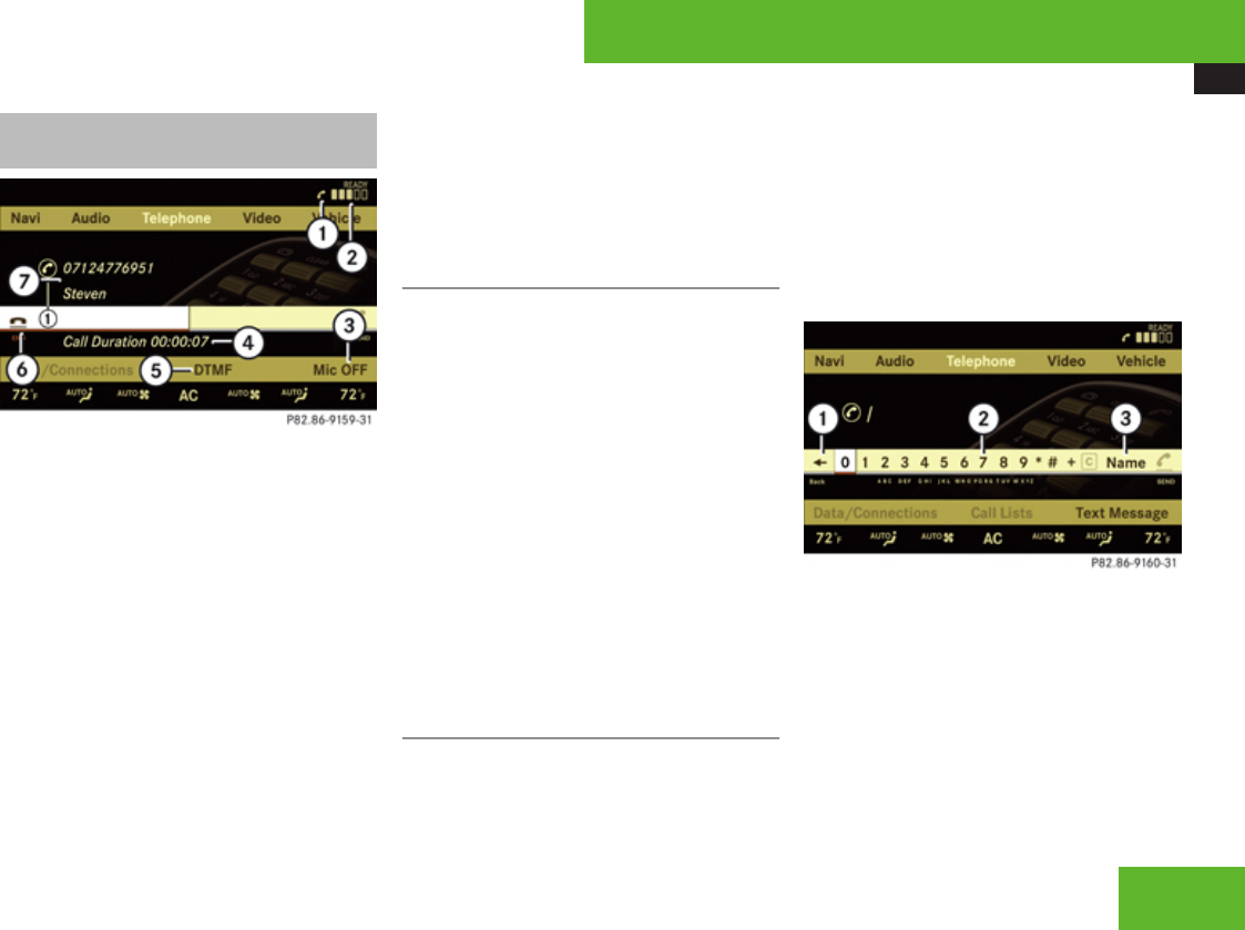
COMAND telephone
167
Functions during a single-call
connection
Example illustration: Telephone mode during a call
1Symbol ° for active telephone
connection (also visible in other operating
modes)
2Signal strength display
3To switch hands-free microphone on or off
4Length of call display
5To send character strings
6To end a call
7Person you are calling
iThe name of the person you are speaking
with can only be seen in display 7 if his or
her telephone number and name have been
saved in the COMAND address book or
phone book on the mobile phone. The
telephone number must also be saved in
the same way in which the person you are
talking to transmits it.
Switching the hands-free microphone
on or off
XSwitching screen to telephone mode:
Call up main telephone menu
(Y page 161).
XSwitching off microphone: Select Mic
OFF and press n.
or
XPress F shortcut button.
If the microphone is switched off, the >
symbol appears in the main area.
XSwitching on microphone: Select Mic
ON.
or
XPress F shortcut button.
The > symbol disappears.
Sending a character string via DTMF
iThis function is not possible with every
mobile phone. If the mobile phone supports
the function, you can use it during the call
connection and also during a call.
Answering machines or other devices can be
controlled by character strings (e. g. for
remote query functions).
Sending character strings via the DTMF
menu
XDuring a call, select DTMF.
The DTMF dialing display appears.
1Back to the call display
2Character entry
3To call up the phone book
Control systems
Z

COMAND telephone
168
XSending individual characters: Rotate
ymz or slide omp and select desired
character.
Each character you select can be seen in
the main area and is sent immediately.
XSending a phone book entry as a
character string: Select Name.
XSelect desired phone book entry.
The entry is immediately sent as a
character string.
iTelephone numbers containing the +
character may impair the function.
XSwitching back to the call display:
Select Y.
Sending character strings via the
telephone keypad
XPress corresponding button on telephone
keypad.
Each character you select is immediately
sent.
iThe + character may impair the function.
Ending an active call
XEnding a call: Select 4END in the call
display.
or
XPress t on the telephone keypad or on
the multifunction steering wheel.
The COMAND display will change to the
previously selected display, if applicable.
Transferring a call
From the hands-free system to the
Bluetooth® headset
iThe use of a Bluetooth® headset requires
Bluetooth® to be activated and the
Bluetooth® headset to be authorized
(Y page 184).
The call transfer is controlled by pressing the
PTT button on the Bluetooth® headset (see
headset operating instructions). Normally, it
is sufficient to press the PTT button once, but
under certain circumstances you may have to
press it a second time.
Once the call has been transferred to the
Bluetooth® headset, all the functions will be
available to you which are described in the
“Functions during a single-call connection”
section (Y page 167).
Exception: “Switching the hands-free
microphone on or off” function
(Y page 167).
From the Bluetooth® headset to the
hands-free system
On most Bluetooth® headsets, you press the
PTT button on the headset twice quickly to
transfer the call (see headset operating
instructions).
From the hands-free system to the
mobile phone
XIf the mobile phone has a folding upper
section: Flip upper section open.
XTake mobile phone out of cradle.
The No telephone inserted message
appears on the COMAND display.
Subsequent operation is only possible
using the mobile phone.
From the mobile phone to the hands-
free system
XInsert mobile phone into cradle.
Once the call has been transferred to the
hands-free feature, all the functions will be
Control systems
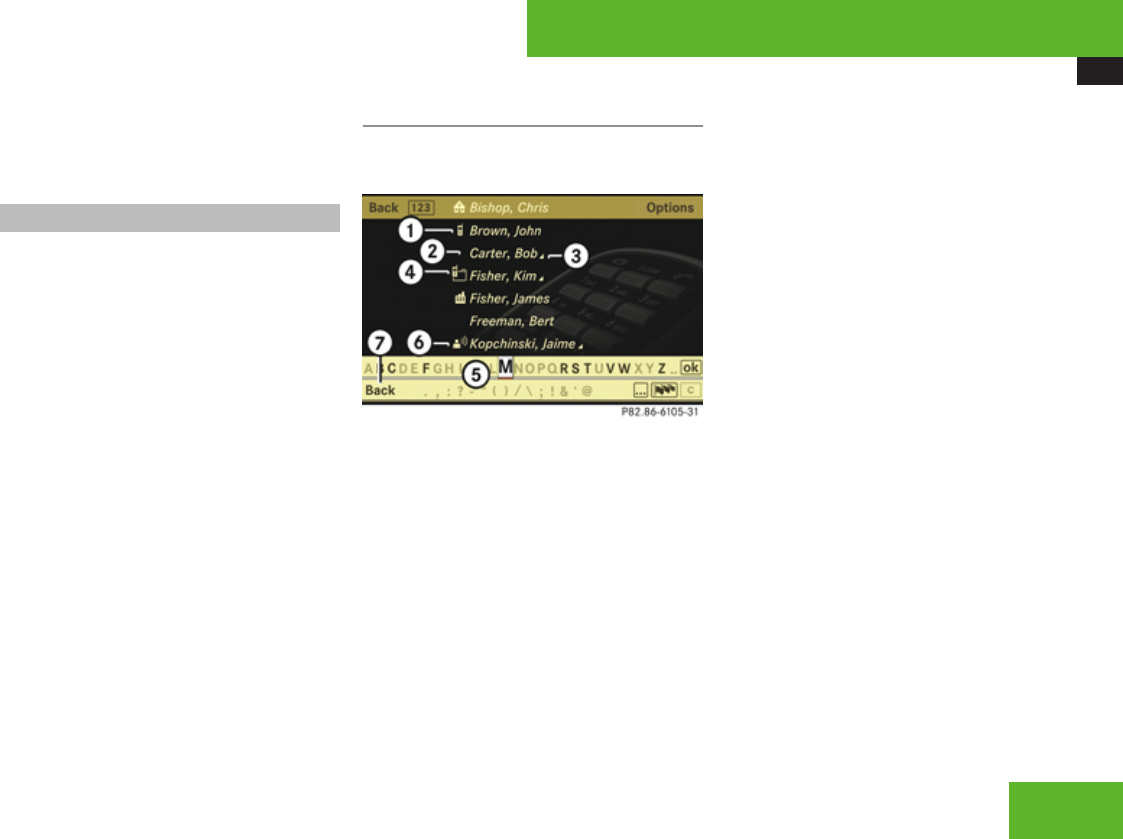
COMAND telephone
169
available to you which are described in the
“Functions during a single- call connection”
section (Y page 167).
COMAND phone book
The COMAND phone book contains both the
COMAND address book entries and mobile
phone entries that have at least one
telephone number.
The COMAND address book entries are
permanently available even when a mobile
phone is not inserted in the cradle.
When the mobile phone is inserted in the
cradle, COMAND will read the phone book
entries in the mobile phone and compares
them with the COMAND address book
entries.
If any of the telephone numbers of a phone
book entry in the mobile phone are the same
as an address book entry, COMAND will only
display the address book entry.
If the entries are not the same, the COMAND
phone book will show the phone book entry
in the mobile phone.
Calling up the COMAND phone book
XSelect Telephone £ Name.
The COMAND phone book appears.
Example illustration: Phone book with name
display and smart speller activated
1Category symbol ¢
2Upper entry from address book (without
category symbol)
3Symbol + for several telephone numbers
(subentries) under the main entry
4Symbol y for summarized entries from
the mobile phone with the same name but
different telephone numbers
5Smart speller
6Voice ¦ entry symbol
7To close the phone book
Entries with category symbol 1 come from
the mobile phone. The following category
symbols are possible:
R¢ = symbol for Mobile category
R@ = symbol for Home category
R\ = symbol for Work category
R. = symbol for Fax category
Rï = symbol for Pager category
R° = symbol for Main category or for
unknown category or for phone entries that
are saved on the SIM card of a GSM mobile
phone
Entries without a category symbol or with the
¦ symbol come from the COMAND address
book.
Entries with the ¦ symbol contain a voice
entry. Voice entries can be added to the
address book (Y page 174). This function is
available in vehicles with Voice Control.
Control systems
Z
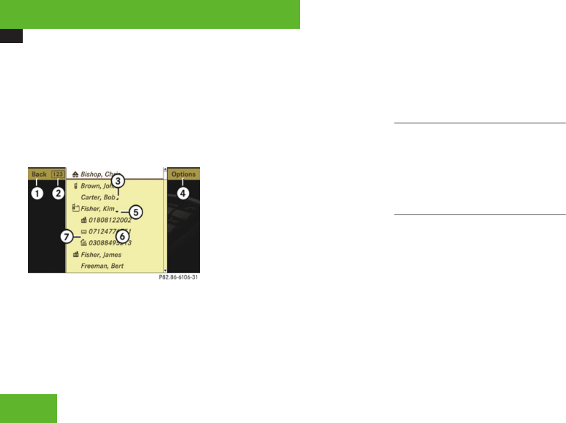
COMAND telephone
170
Switching between the smart speller and
the list
XSwitching from the smart speller to the
list: Slide qm repeatedly or press n until
the smart speller is hidden.
or
XRotate ymz or slide omp and select
d.
The smart speller is hidden.
Example illustration: List of phone book entries
with name display and hidden smart speller
1Back to smart speller
2To switch phone book display (n or
g)
3Symbol + for several telephone numbers
(subentries) under the main entry,
subentry list is closed
4To call up options
5Symbol / for open subentry list
6List of phone book entries
7Subentry list with category symbols and
telephone numbers
iThe following options are available under
Options menu item 4:
RDisplaying details about an entry
(Y page 171)
RCreating a new entry in the address book
(Y page 171)
RDeleting an entry (Y page 172)
RSaving a phone book entry from mobile
phone in the address book
(Y page 173)
RAdding a telephone number to an
address book entry (Y page 174)
XSwitching from the list to the smart
speller: Select Back from the list.
or
XPress back button L in the center
console (Y page 90).
XChanging phone book display in the
list: Select n or g.
The screen changes to telephone number
or name display.
Closing the COMAND phone book
XIn the smart speller, select Back.
or
XPress back button L in the center
console (Y page 90).
Selecting an entry in the COMAND
phone book
Selecting entries using the smart speller
XSwitch from the list to the smart speller if
necessary.
XChanging smart speller language:
Select !.
XSelect desired language.
XChanging smart speller character set:
Select #.
Depending on the previous setting, you will
change to letters with special characters or
to numbers with special characters.
Control systems

COMAND telephone
171
XEntering characters: Select the
characters of the entry you are searching
for one by one.
XDeleting individual characters:
Select ) and briefly press n.
Each time you enter or delete a character,
the closest match will be displayed at the
top of the list.
XDeleting an entire entry: Select ) and
press and hold n until the entry is deleted.
XCanceling search: Switch from the smart
speller to the list.
The entry at the top of the list is
automatically highlighted.
Selecting using the list
XIf necessary, switch from the smart speller
to the list.
XRotate ymz or slide qmr until the desired
entry is highlighted.
Selecting subentries
XSelect an entry with the + symbol and
press n.
The + symbol changes to / and the
subentries are displayed.
XRotate ymz or slide qmr until the desired
subentry is highlighted.
Displaying details of an entry
COMAND can also show a shortened entry in
its entirety. For entries featuring subentries,
the detailed view is only available for the
subentries and not for the main entry.
XSelect entry (Y page 170).
XSelect Options £ Details.
The detailed view appears.
XClosing detailed view: Slide qmr or
omp or press n or back button L in
the center console (Y page 90).
Starting to dial the number of an entry
XSelect entry (Y page 170).
XPress n.
or
XPress s on the telephone keypad.
A list appears if the entry contains
subentries.
XSelect desired subentry.
XPress n again.
or
XPress s on the telephone keypad.
Assigning a New Entry in the Address
Book
iThis function is used to create a new entry
in the address book and to enter the data
(first name, last name and telephone
number) manually.
XSelect Options £ New Entry in the
COMAND phone book list.
XSelecting a number category: Select a
category, e. g. Home.
Control systems
Z
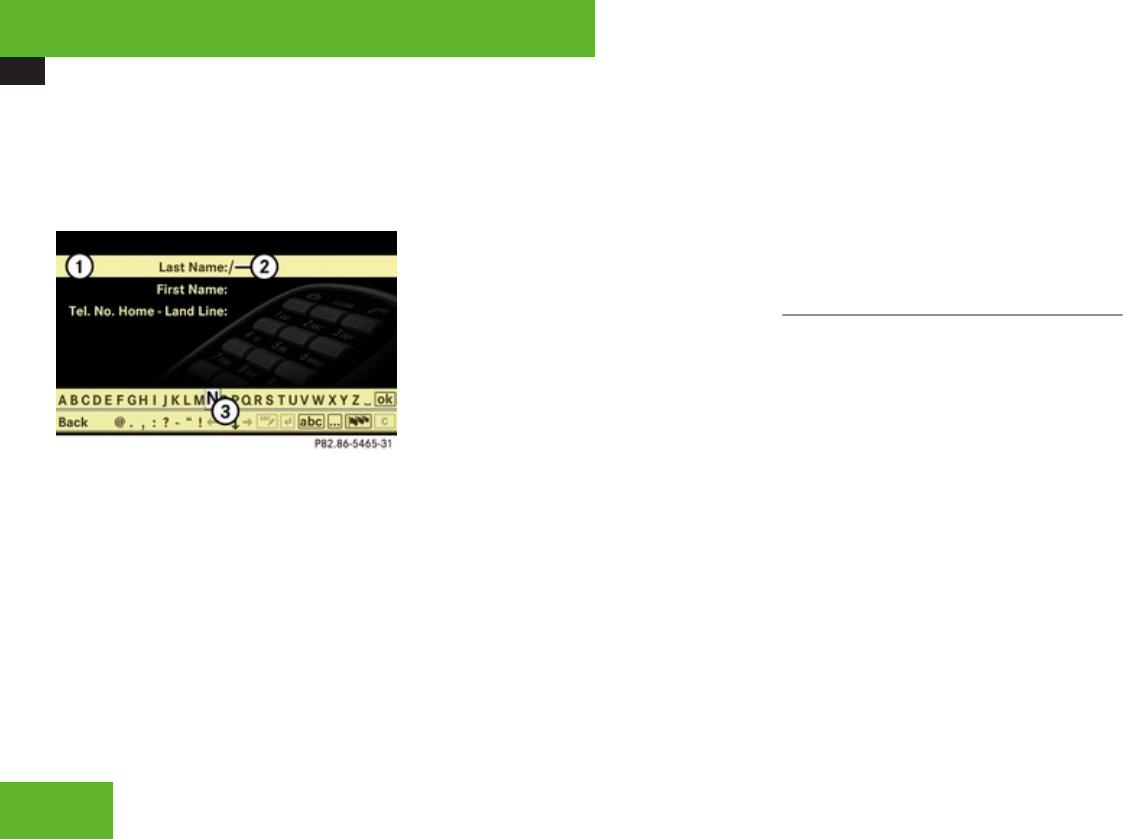
COMAND telephone
172
XSelecting a telephone category: Select a
category, e. g. Land Line.
XConfirming selection: Select Save.
The input menu appears with the data
fields.
1Data field
2Input mark (cursor)
3Input characters
XChanging data field: Slide qmr
repeatedly until desired data field is
highlighted.
or
XSelect [ or ] repeatedly until desired
data field is highlighted.
XEntering data into a field: Select all
characters one by one from the input
characters line 3.
XToggling upper and lower case for the
input characters: Select & or (.
XChanging language for the input
characters: Select !.
XSelect desired language.
XChanging character set for the input
characters: Select #.
Depending on the previous setting, you will
change to letters with special characters or
to numbers with special characters.
XDisplaying special characters as input
characters: Select ! £ Symbols.
XReturning input characters to normal
characters: Select ! £ the desired
language.
XMoving cursor in the data field: Select
Y or Z.
XDeleting individual characters:
Select ) and briefly press n.
The character to the left of the cursor is
deleted.
XDeleting an entire entry: Select ) and
press and hold n until the entry is deleted.
XSaving an entry: Select d.
XCanceling an entry: Select Back.
If one of the data fields contains data, a
prompt will appear asking whether you
want to save the entry.
XSelect Yes or No.
The entry will either be saved or not,
depending on your selection.
Deleting an entry
iIt is not possible to delete a phone book
entry from the mobile phone using the
COMAND phone book.
The deletion rules may vary, depending on the
entry selected:
RUpper entry selected from the address
book:
The entry is deleted from the COMAND
phone book and also from the address
book, if the address book entry only
contains telephone numbers.
RSubentry of an address book entry
selected:
The subentry is deleted from the COMAND
phone book and from the address book.
Control systems
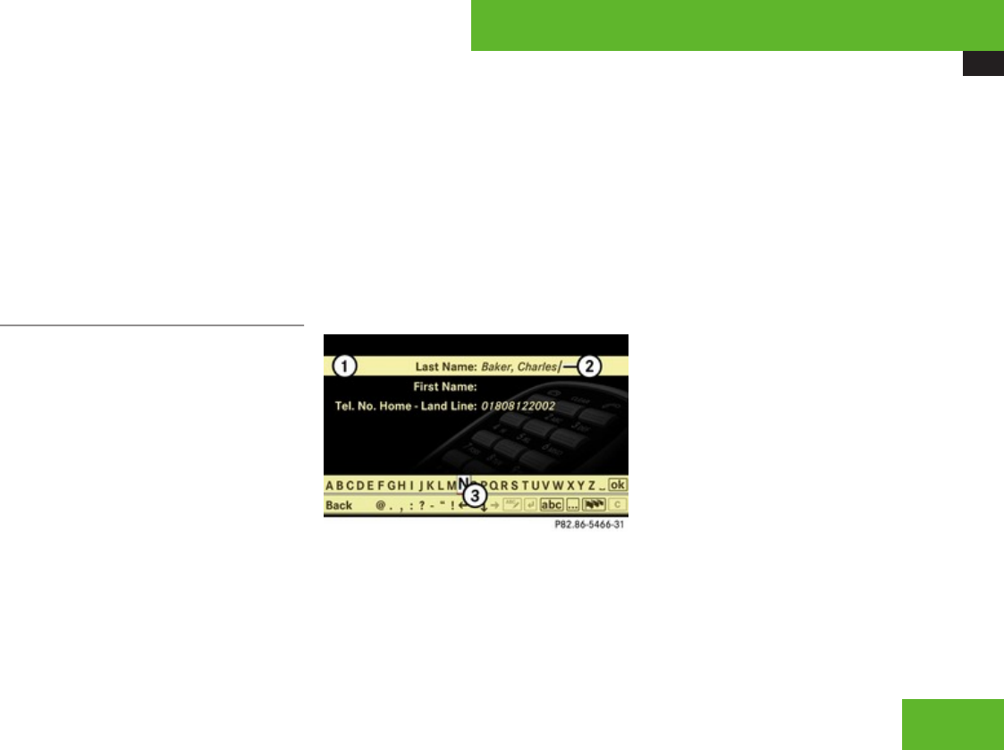
COMAND telephone
173
XDeleting: Select entry (Y page 170).
XSelect Options £ Delete.
A prompt appears asking whether the entry
should be deleted.
XSelect Yes or No.
Once Yes has been selected, the entry will
be deleted according to the rules
mentioned above.
Saving a phone book entry from the
mobile phone in the address book
iThis function is used to save an existing
phone book entry from the mobile phone in
the address book. The following options are
available:
RSaving as a new address book entry
RAdding a telephone number to an
existing address book entry
Saving as a new address book entry
XSelect phone book entry from mobile
phone (Y page 170).
iAll entries with category symbols (¢, @,
\, ., ï or °) are phone book entries
in the mobile phone (Y page 169).
XSelect Options £ Save £ New Entry.
XSelecting a number category: Select a
category, e. g. Home.
XSelecting a telephone category: Select a
category, e. g. Land Line.
XConfirming selection: Select Save.
The input menu appears with the data
fields. The data field for the telephone
number is filled in automatically. The data
field for the last name is also filled when the
entry to be saved contains a name.
1Data field
2Input mark (cursor)
3Input characters
XProceed as described in the “Changing
data field” paragraph in the “Assigning a
New Entry in the Address Book” section
(Y page 171).
Adding a telephone number to an existing
address book entry
XSelect phone book entry from mobile
phone (Y page 170).
iAll entries with category symbols (¢, @,
\, ., ï or °) are phone book entries
in the mobile phone (Y page 169).
XSelect Options £ Save £ Add.
XSelecting a number category: Select a
category, e. g. Home.
XSelecting a telephone category: Select a
category, e. g. Land Line.
XConfirming selection: Select Save.
The search menu for address book entries
appears.
XSearch for desired entry using smart speller
function.
iThere is a detailed description of how to
search for an address book entry in the
“Searching for an address book entry”
section (Y page 176).
Control systems
Z

COMAND telephone
174
XAfter selecting an entry, press n.
If there are fewer than four numbers
assigned to the selected entry in the
selected number category, COMAND will
save the data.
If four numbers are saved for the selected
entry, a prompt will appear asking whether
you want to overwrite one of the existing
numbers.
XSelect Yes or No.
If you select Yes, a selection list will appear
containing the four existing numbers.
XSelect number to be overwritten.
COMAND overwrites the selected number
with the new data.
Adding a telephone number to an
address book entry
iThis function is used to add a telephone
number to an existing address book entry.
The telephone number can be entered
manually.
XSelect address book entry (Y page 170).
iAll entries with the ¦ symbol or without
a symbol are address book entries.
XSelect Options £ Add Number.
iAdd Number does not function if you have
selected the main entry for an address
book entry with subentries.
XSelecting a number category: Select a
category, e. g. Home.
XSelecting a telephone category: Select a
category, e. g. Land Line.
XConfirming selection: Select Save.
If four numbers are saved for the entry in
the selected number category, a prompt
will appear asking whether one of the
existing numbers should be overwritten.
Select Yes or No.
If you select Yes, a selection list will appear
containing the four existing numbers.
Select number to be overwritten.
The input menu appears with the data field
for entering the new telephone number.
XEntering digits: Select all digits one by one
from the input characters.
XMoving cursor in the data field: Select
Y or Z.
XDeleting individual digits: Select ) and
briefly press n.
The digit to the left of the cursor is deleted.
XDeleting an entire number: Select ) and
press and hold n until the number is
deleted.
XSaving entry: Select d.
XCanceling an entry: Select Back.
If you have already entered data, a prompt
will appear asking whether the entry should
be saved.
XSelect Yes or No.
The entry will either be saved or not,
depending on your selection.
COMAND address book
GWarning!
Please devote your attention first and
foremost to the traffic situation you are in.
Before your journey, please familiarize
yourself with the address book functions.
Only use the COMAND when road and
traffic conditions permit you to do so.
Otherwise you could be involved in an
accident in which you or others could be
injured.
General notes
The address book contains the entries that
are saved in the COMAND address book
memory. The entries are permanently
available even if the phone is not inserted in
the cradle. When you insert the mobile phone
Control systems
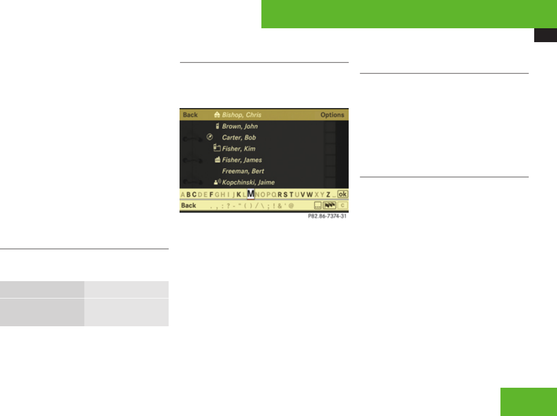
COMAND telephone
175
into the cradle, COMAND reads-in the phone
book entries saved in the mobile phone and
stores the entries as a separate list from the
COMAND address book. This list is a copy of
the phone’s phone book. This can take
several minutes, depending on how many
entries the phone book and the address book
contain. After the read-in process, the
COMAND compares the phone book entries
with the address book entries. If all of the
telephone numbers of a phone book entry in
the mobile phone are present in an address
book entry, the address book shows only the
address book entry. If not, the address book
also shows the phone book entry in the
mobile phone.
Address book menu overview
iThe components and operating principles
of COMAND can be found on (Y page 82).
Search New Entry
Search for an
address book entry
Create new address
book entry
Calling up the address book
XSelect Telephone £ Data/
Connections £ Address Book.
The main address book display appears.
iFor phone book entries in the mobile
phone that contain a name and a telephone
number, you will see the name and the
number. If a phone book entry in the mobile
phone contains several telephone
numbers, you will see the message
Multiple Numbers instead of a telephone
number.
Selecting an entry in the main address
book display
XSlide qm to select the main area.
XSlide qmr or rotate ymz to select an
entry.
or
XSearch for an entry with the smart speller
(Y page 176).
Creating a new address book entry
iPlease observe the following when
creating a new address book entry:
You can define your own address in the
destination memory in navigation mode.
When defining the address, you can
transfer data already entered as an address
book entry.
In the address book entry, the city and
street must be spelled in the same way as
the destination entry so that the data
matches the digital map data.
In order for the state/province to match
the map data, its complete name or
abbreviation may be entered.
Control systems
Z
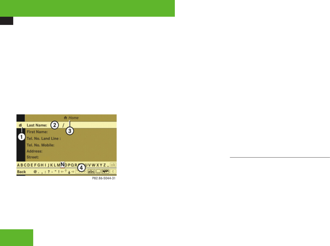
COMAND telephone
176
Examples:
RFlorida or FL
RColorado or CO
RAlberta or AB
ROntario or ON
XSelect Telephone £ Data/
Connections £ Address Book £
Options £ New Entry.
The input menu appears with the data fields
and the input characters.
Example illustration: Input menu for private data
1To switch between work and home data
(\ or @ symbol)
2Selected data field with input mark
(cursor)
3Display of set data type – in example
display, home data is set (@ symbol and
Home display)
4Input characters
XSwitching between private and
business data: Select symbol 1.
The display switches to private or business
data, depending on the previous status.
XChanging data field: Slide qmr
repeatedly until desired entry is
highlighted.
or
XSelect [ or ] repeatedly until desired
entry is highlighted.
XEntering data into a field: Select desired
characters one by one from the input
characters.
XToggling upper and lower case for the
input characters: Select & or (.
XChanging language for the input
characters: Select !.
XSelect desired language.
XChanging character set for the input
characters: Select #.
Depending on the previous setting, you will
change to letters with special characters or
to numbers with special characters.
XMoving cursor in the data field: Select
Y or Z.
XDeleting individual characters:
Select ) and briefly press n.
The character to the left of the cursor is
deleted.
XDeleting an entire entry: Select ) and
press and hold n until the entry is deleted.
XSaving an entry: Select d.
XCanceling an entry: Select Back.
If one of the data fields contains new data,
a prompt will appear asking whether you
want to save the entry.
XSelect Yes or No.
The entry will either be saved or not,
depending on your selection.
Searching for an address book entry
XSelect Telephone £ Data/
Connections £ Address Book.
The search menu appears with the smart
speller.
Control systems
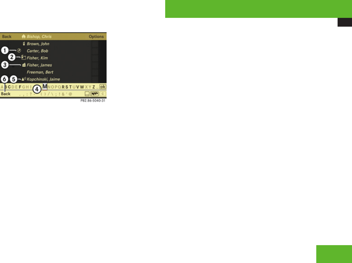
COMAND telephone
177
1Symbol ¤ for complete address data
from the navigation system
2Symbol y for summarized entries from
the mobile phone with the same name but
different telephone numbers
3Category symbol \
4Smart speller
5Symbol ¦ for voice entry
6Back to the main address book display
Entries with category symbol 3 come from
the mobile phone. The following category
symbols are possible:
R¢ = symbol for Mobile category
R@ = symbol for Home category
R\ = symbol for Work category
R. = symbol for Fax category
Rï = symbol for Pager category
R° = symbol for Main category or for
unknown category or for phone entries that
are saved on the SIM card of a GSM mobile
phone
Entries without a category symbol or with the
¦ or ¤ symbols come from the COMAND
address book. All other entries come from the
mobile phone and are only visible when the
mobile phone is in the cradle.
It is possible to add voice entries. Entries with
the ¦ symbol contain a voice entry
(Y page 182).
Entries with the ¤ symbol contain complete,
navigable address data from the navigation
system that correspond to digital map data.
It is possible to quickly start route guidance
to these types of entry (Y page 181).
Switching from the smart speller to the
list
XSlide qm repeatedly or press n until the
smart speller is hidden.
or
XSelect d.
Switching from the list to the smart
speller
XSelect Back from the list.
Searching via the smart speller
XSwitch from the list to the smart speller if
necessary.
XChanging smart speller language:
Select !.
XSelect desired language.
XChanging smart speller character set:
Select #.
Depending on the previous setting, you will
change to letters with special characters or
to numbers with special characters.
XEntering characters: Select the
characters one by one of the entry you are
searching for.
XDeleting individual characters:
Select ) and briefly press n.
Each time you enter or delete a character,
the closest match will be displayed at the
top of the list.
XDeleting an entire entry: Select ) and
press and hold n until the entry is deleted.
Control systems
Z
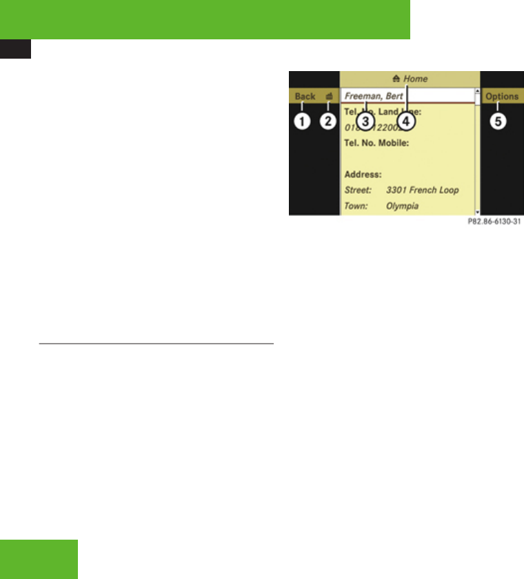
COMAND telephone
178
XCanceling search: Switch from the smart
speller to the list (Y page 177).
The entry at the top of the list is
automatically highlighted.
XGoing back to main address book
display: If necessary, switch from the list
to the smart speller (Y page 177) and select
Back in the smart speller.
Searching via the list
XIf necessary, switch from the smart speller
to the list (Y page 177).
XRotate ymz or slide qmr until desired
entry is highlighted on the list.
Displaying a complete address book
entry
Searching for the desired entry
XSearch for an address book entry
(Y page 176).
or
XSelect an address book entry in the main
address book menu (Y page 175).
XPress n.
The detailed view appears.
Example illustration: Detailed view for private data
1To go back to the previous menu
2To switch between work and home data
( symbol \ or @)
3Selected data field
4Display of set data type – in example
display, home data is set (@ symbol and
Home display)
5To call up options
iThe options available under Options
menu item 5 depend on which data field
3 is selected.
The following options may be available:
RDisplaying abbreviated content in full
(Y page 179)
RChanging an address book entry
(Y page 179)
RChanging the description of a telephone
number data field (Y page 180)
RAdding a telephone number data field
(Y page 180)
RCalling a number saved in an entry
(Y page 181)
RStarting route guidance to an entry
(Y page 181)
ROptions for voice entries (Y page 182)
Switching between private or business
data
XSelect symbol 2.
The display switches to private or business
data, depending on the previous status.
Selecting a different data field
XRotate ymz or slide qmr.
Control systems
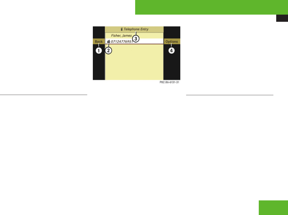
COMAND telephone
179
Displaying abbreviated content in full
XSelect Options £ Details.
The display is shown in full.
XClosing entire display: Slide omp or
press n.
Closing the detailed view
XSelect Back.
Displaying of a complete phone book
entry in the mobile phone
iThe mobile phone must be inserted in the
cradle.
Searching for the desired entry
XSearch for a phone book entry in the mobile
phone (Y page 170).
XPress n.
The detailed view appears.
1To go back to the previous menu
2Category symbol
3Display for phone book entry in mobile
phone
4To call up options
iIf a phone book entry in the mobile phone
has more than one telephone number, you
will see all telephone numbers with the
respective category symbol 2 in the
detailed view.
iThe options available under Options
menu item 4 depend on which data field
3 is selected.
The following options may be available:
RCalling a number saved in an entry
(Y page 181)
RSaving a phone book entry from mobile
phone in the address book
(Y page 173)
Closing the detailed view
XSelect Back.
Changing an entry
Changing an address book entry
XSearch for an address book entry
(Y page 176).
or
XDisplay the details of an address book entry
(Y page 178).
The input menu appears with the data
fields.
XSelect Options £ Change.
XProceed as described in the “Switching
between private and business data”
paragraph in the “Creating an new address
book entry” section (Y page 175).
Control systems
Z

COMAND telephone
180
Changing the description of a telephone
number data field
iThis function is not possible for phone
book entries in the mobile phone.
XDisplay the details of an entry and highlight
the telephone number data field
(Y page 178).
XSelect Options £ Change Category.
XSelect a number category, e. g. Home.
XSelect a telephone category, e. g. Land
Line.
XSelect Save.
COMAND saves the data if there are fewer
than four numbers assigned to the entry
you are searching for in the selected
number category.
Otherwise, you will see a prompt asking
whether one of the existing numbers
should be overwritten.
XSelect Yes or No.
If you select Yes, a selection list will appear
containing the four existing numbers.
XSelect number to be overwritten.
COMAND overwrites the selected number
with the new data.
Adding to a telephone number data field
iOne address book entry may contain up
to four data fields for private telephone
numbers and four data fields for business
telephone numbers.
This function is not possible for phone book
entries in the mobile phone.
XDisplay the details of an entry and highlight
the telephone number data field
(Y page 178).
XSelect Options £ Add Number.
XSelect a number category, e. g. Home.
XSelect a telephone category, e. g. Land
Line.
XSelect Save.
COMAND adds the data field to the entry if
there are fewer than four numbers assigned
to the entry in the selected number category.
You can now enter a number into the data
field.
XProceed as described from the “Entering
data into a field” operating step in the
“Creating a new address book entry”
section (Y page 175).
If four numbers are already saved for the
entry in the selected number category, a
prompt will appear asking whether one of the
data fields should be overwritten.
XSelect Yes or No.
If you select Yes, a selection list will appear
containing the four data fields.
XSelect field to be overwritten.
COMAND deletes the number of the
selected field. You can now enter a new
number into the data field.
XProceed as described from the “Entering
data into a field” operating step in the
“Creating a new address book entry”
section (Y page 175).
Deleting an entry
iYou cannot delete phone book entries
from the mobile phone.
XSearch for desired entry (Y page 176).
XSelect Options £ Delete.
A deletion prompt appears.
XSelect Yes or No.
The entry will either be deleted or not,
depending on your selection.
Control systems

COMAND telephone
181
Calling a number saved in an entry
iTo do this, COMAND must be equipped
with a telephone. The mobile phone must
be inserted in the cradle.
XDisplay the details of an entry and highlight
the telephone number data field
(Y page 178).
XPress n and select Call.
or
XSelect Options £ Call.
In both cases, the telephone connects the
call. The COMAND display is showing the
telephone mode screen.
Starting route guidance to an entry
XSearch for an address book entry
(Y page 176).
XDisplay the details of an entry and highlight
the address data field (Y page 178).
XSelect Options £ Navigate.
or
XPress n.
iPressing n only functions if one of the
address data fields contains data.
Further operation depends on whether the
address data is complete and matches the
digital map data of the navigation system. It
does not match, for example, if it is not
spelled in the same way as the destination
entry.
Address data is complete and matches
digital map
If Navigate is selected, the navigation
system starts the route calculation.
Address data is incomplete or does not
match digital map
iFor the route calculation, the navigation
system requires the correct spellings of the
state (province), the city or zip code, the
street and under some circumstances, the
house number. The city and street must be
spelled in the same manner as the
destination entry.
The state (province) can be spelled as an
entire name or as an abbreviation.
Examples:
RFlorida or FL
RColorado or CO
RAlberta or AB
ROntario or ON
If Navigate is selected, a message appears
indicating that the address is incomplete.
XClosing message: Select OK.
Depending on which data is missing or cannot
be found on the digital map, you must now
either:
Rselect a state (province)
Rselect a county
Ror enter a city
Ror enter a street
Ror enter a house number
XSelecting a state (province): Select
desired state (province) from the list.
XSelecting a county: Select desired county
from the list.
XEntering a city: Proceed as described for
destination entry in the “Entering a city”
section (Y page 116).
XEntering a street: Proceed as described
for destination entry in the “Entering a
street” section (Y page 119).
XEntering a house number: Proceed as
described for destination entry in the
“Entering a house number” section
(Y page 123).
Control systems
Z

COMAND telephone
182
iIf you have added data, COMAND saves
your additions. This means that you do not
need to reenter this additional data later
on.
The COMAND memory saves the additional
data in a special field, which cannot be
displayed. The data, which you have
entered in the address book initially in the
display, remains unchanged.
If all data is available and matches the digital
map data, the navigation system starts the
route calculation.
Voice entries
iFor voice entries, your vehicle must be
equipped with Voice Control. You can not
add voice entries to address book entries
that have been read-in from the phone
book of the mobile phone.
Adding or changing a voice entry
iYou can add one voice entry per address
book entry.
XSearch for the address book entry with or
without a voice entry (Y page 176).
XSelect Options £ Voice Name £ Add
or Change.
Subsequent operation is controlled by
voice. Voice Control guides you through the
dialogs.
Deleting a voice entry
XSearch for the address book entry with a
voice entry (Y page 176).
XSelect Options £ Voice Name £
Delete.
A deletion prompt appears.
XSelect Yes or No.
COMAND deletes the voice entry
depending on your selection.
Listening to a voice entry
XSearch for the address book entry with a
voice entry (Y page 176).
XSelect Options £ Voice Name £ Read
Aloud.
You will hear the voice entry.
Saving a phone book entry from mobile
phone in the COMAND address book
Saving a phone book entry from mobile
phone as new address book entry
iThe mobile phone must be inserted in the
cradle and the COMAND have read out the
mobile phone book data. This can take
several minutes, depending on how many
entries each phone book contains.
XSearch for phone book entry in mobile
phone (Y page 176).
or
XDisplay details of a phone book entry in the
mobile phone (Y page 171).
XSelect Options £ Save £ New Entry.
XSelect a number category, e. g. Work.
XSelect a telephone category, e. g. Mobile.
XSelect Save.
The input menu appears with the data
fields. The name and the telephone number
are entered automatically.
Control systems
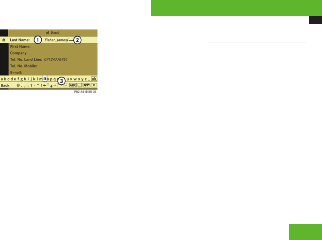
COMAND telephone
183
1Data field
2Input mark (cursor)
3Input characters
XProceed as described in the “Changing a
data field” paragraph in the “Creating a new
address book entry” section (Y page 175).
Saving a phone book entry from the
mobile phone in an existing address book
entry
iThe mobile phone must be inserted in the
cradle.
XSearch for a phone book entry in the mobile
phone (Y page 176).
or
XDisplay details of a phone book entry in the
mobile phone (Y page 171).
XSelect Options £ Save £ Add.
XSelect a number category, e. g. “Home.
XSelect a telephone category, e. g. Land
Line.
XSelect Save.
The search menu for address book entries
appears.
XSearch for desired entry.
iThere is a detailed description of how to
search for an address book entry in the
“Searching for an address book entry”
section (Y page 176).
XAfter selecting an entry, press n.
COMAND saves the data if there are fewer
than four numbers assigned to the selected
entry in the selected number category.
Otherwise, you will see a prompt asking
whether one of the existing numbers
should be overwritten.
XSelect Yes or No.
If you select Yes, a selection list will appear
containing the four existing numbers.
XSelect the number to be overwritten.
COMAND overwrites the selected number
with the new data.
Importing data from external
Bluetooth® devices
You can import vCards from external
Bluetooth® devices into the address book.
Please keep the following in mind:
RBluetooth® is activated in COMAND
(Y page 184) and in the device concerned.
RThe external device must be able to send
vCards by Bluetooth®.
RThe external device is inside the vehicle,
switched on and authorized (Y page 184).
XImporting: Start data transfer on the
external device (see operating instructions
of the device concerned).
If there is no address book entry with the
same first name and last name, COMAND
imports the data.
If there is already an address book entry
with the same first name and last name, a
prompt will appear asking whether the
existing data should be overwritten.
XSelect Yes or No.
The existing address book entry will be
overwritten or not, depending on your
selection.
Control systems
Z

COMAND telephone
184
Bluetooth® settings
General information about Bluetooth®
Bluetooth® technology is the standard for
short-range wireless technologies, suitable
for transmitting voice and data. Bluetooth®
can be used to exchange vCards or make calls
using a headset.
Bluetooth® technology uses the freely
available ISM (Industrial Scientific Medical)
wireless network that works at 2.45 GHz.
Ranges of up to 33 ft (10 m) are possible with
Bluetooth®.
Activate or deactivate Bluetooth®
XSelect Telephone £ Data/
Connections £ Bluetooth £
Deactivate Bluetooth.
You have activated or deactivated
Bluetooth®. A checkmark appears when
Bluetooth® is deactivated.
Connecting Bluetooth® devices
iTo connect a Bluetooth® device, the
Bluetooth® function must be activated in
COMAND and in the device concerned. The
Bluetooth® device must also be set to
“visible” or “findable” in order for COMAND
to find and display it. For the setting
procedures, please see the operating
instructions for the Bluetooth® device.
It is possible to establish a Bluetooth®
connection between COMAND and the
following types of device:
RMobile phone (only for transferring
business cards)
RHeadset
RLaptop/PDA
You can connect up to twelve devices to
COMAND but only one device can be active
at a time.
The connection process includes searching
for the device and its subsequent
authorization.
Calling up the Bluetooth® device list and
searching for devices
XCalling up the list: Select Telephone
£ Data/Connections £ Bluetooth
£ Search for Bluetooth devices.
When you call up the list for the first time
after switching on COMAND, the search for
devices in the reception range starts
automatically. You will see a display to this
effect.
The device list appears after a short while.
XCanceling search: Select Cancel.
The second time you call up the list, and each
time thereafter, the device list appears
immediately if COMAND has not been
switched off and on again in the meantime.
XStarting search manually: Select
Update.
The device list can contain the following
devices:
RAll detected devices, whether authorized or
not.
RAll authorized devices, whether detected or
not.
Control systems

COMAND telephone
185
1Authorized and detected device – device
and padlock symbol are the same color
2Device which was not detected, but which
has been authorized in the past – device
and padlock symbol are different colors
(the device may be switched off or not in
the vehicle, for example)
3Newly detected device - not yet
authorized (no symbol)
iIf the device list already contains twelve
authorized devices, you must revoke
authorization for one of the authorized
devices. Then you must switch this device
off and then restart the search. Any new
devices for which you would like to search
will otherwise not appear in the list.
Displaying details of a Bluetooth®
device
XCall up the Bluetooth® device list
(Y page 184).
XSelect desired device.
XSelect Details.
The detailed display for this device
appears.
XClosing detailed display: Slide qmr or
ymz.
Authorizing a Bluetooth® device
XCall up the Bluetooth® device list
(Y page 184).
XSelect unauthorized device.
XSelect Authorize.
The input menu for the passkey appears.
iThe passkey is any one to sixteen-digit
number which you can set yourself. You
must enter the same number in COMAND
and also in the device to be authorized.
iOn devices which do not have an input
keypad (e. g. headsets), the passkey is
predetermined. In this case, it is not
necessary to enter the number on the
device itself. You will usually find the
passkey in the operating instructions for
the device.
XEntering passkey into COMAND: Select
the digits one by one.
XDeleting digits: Select ) and briefly
press n.
XCanceling entry into COMAND: Select
Back.
XConfirming entry into COMAND: Select
d.
XIf necessary, enter the same passkey into
the Bluetooth® device (see the operating
instructions for the device).
The device is authorized.
Deauthorizing a Bluetooth® device
XCall up the Bluetooth® device list
(Y page 184).
XSelect authorized device.
XSelect De-authorize.
A prompt appears asking whether you
really want to deauthorize this device.
XSelect Yes or No.
If you select Yes, the device will be
deauthorized.
Control systems
Z
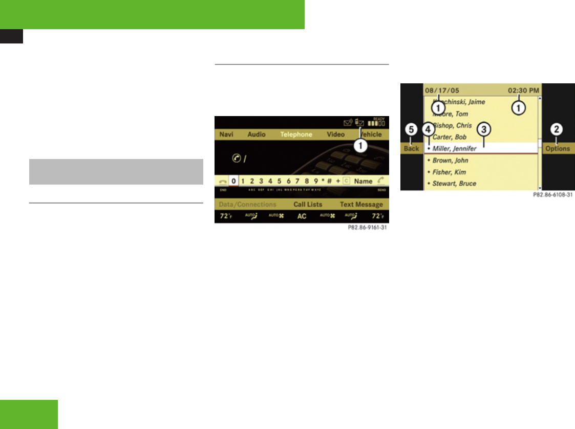
COMAND telephone
186
iIf you de-authorize a device which has
been authorized in the past and which is not
detected in the search, this device will no
longer be displayed in the device list.
Devices which have been authorized in the
past but which are not detected in the
search are either not switched on or not in
the vehicle.
SMS messages (Short Message
Service)
SMS functions
The following functions are available:
RReceive
RRead
The following conditions must be fulfilled in
order to use the functions:
RThe mobile phone is inserted in the cradle
and switched on.
RThe PIN has been entered (only GSM
mobile phones).
RThe mobile phone is logged into a mobile
network.
RThe mobile phone book must be
downloaded and available in COMAND.
Inbox
Calling up the SMS inbox
XSelect Telephone.
The main telephone menu appears.
1Symbol ð for unread messages in the
SMS inbox
iThe ð symbol only appears for those
messages which are received while the
mobile phone is inserted in the cradle.
XSelect Text Message.
The SMS inbox appears.
iText Message does not function if the
SMS inbox contains no SMS messages. The
SMS inbox only shows the messages which
are received while the mobile phone is
inserted in the cradle.
1Date and time the highlighted SMS
message was received
2To call up options
3Highlighted SMS message
4Symbol ñ for unread SMS message
5Back to main telephone menu
iThe SMS messages are sorted by the date
and time they were received. The most
recent message is at the top of the list.
If the name and telephone number of the
sender is saved in the address book or
phone book of the mobile phone, you will
see the name of the sender in the SMS
inbox. Otherwise, you will see the
telephone number of the sender.
Control systems
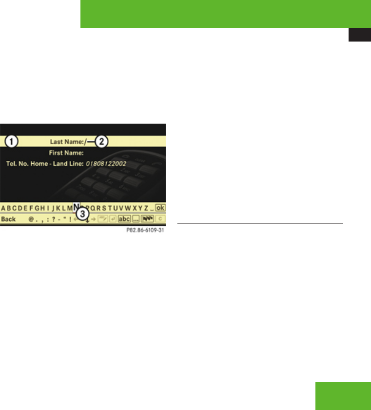
COMAND telephone
187
Selecting an SMS message
XRotate ymz or slide qmr and then
press n.
Showing abbreviated sender display in
full
XSelect SMS message £ Options £
Details.
The detailed view appears.
XClosing detailed view: Slide qmr or
press n.
Calling an SMS sender
XSelect SMS message £ Options £
Call.
The telephone connects the call.
Saving SMS sender as new COMAND
address book entry
XSelecting an SMS message: In the SMS
inbox, select a message £ Options £
Save Number £ New Entry.
XSelecting a number category: Select a
category, e. g. Home.
XSelecting a telephone category: Select a
category, e. g. Land Line.
XSaving: Select Save.
The input menu appears with the data
fields. The data field for the telephone
number is filled in automatically.
1Data field
2Input mark (cursor)
3Input characters
XProceed as described in the “Changing
data field” paragraph in the “Assigning a
New Entry in the Address Book” section
(Y page 171).
Adding an SMS sender’s telephone
number to an existing address book entry
XSelecting an SMS message: In the SMS
inbox, select a message £ Options £
Save Number £ Add.
XProceed as described in the “Selecting a
number category” paragraph in the “Adding
a telephone number to an existing address
book entry” section (Y page 173).
Exiting the SMS inbox
XSelect Back.
The main telephone menu appears.
Reading an SMS message
XIn the SMS inbox, select an SMS message
and press n.
The SMS message appears.
Control systems
Z

COMAND FM/AM radio
188
Using data in a text message
iIf the SMS message contains telephone
numbers or navigable address data, you
can select this data and place a telephone
call or transfer the address data to the
navigation system.
XSelecting data from the text: Rotate
ymz or slide qmr.
XUsing data: Press n £ Use.
If you have selected a telephone number,
the telephone connects the call. If you have
selected a navigable address, it is
transferred to the navigation system.
Calling an SMS sender
iThis function is not possible with all SMS
senders.
XPress n £ Call.
The telephone connects the call.
Saving SMS sender as new address book
entry
iThis function is not possible with all SMS
senders.
XPress n £ Save Number £ New
Entry.
XProceed as described in the “Selecting a
number category” paragraph in the “Saving
SMS sender as new COMAND address
book entry” section (Y page 187).
Adding an SMS sender’s telephone
number to an existing address book entry
XPress n £ Save Number £ Add.
XProceed as described in the “Selecting a
number category” paragraph in the “Adding
a telephone number to an existing address
book entry” section (Y page 173).
Closing an SMS message and returning to
SMS inbox
XPress n £ Back.
COMAND FM/AM radio
Safety notes
GWarning!
Please devote your attention first and
foremost to the traffic situation you are in.
Before your journey, please familiarize
yourself with the radio functions.
Only use the COMAND when road and
traffic conditions permit you to do so.
Otherwise you could be involved in an
accident in which you or others could be
injured.
Submenu overview
iThe components and operating principles
of COMAND can be found on (Y page 82).
Control systems
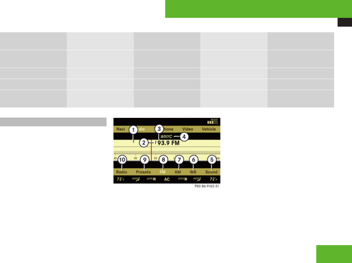
COMAND FM/AM radio
189
Radio
(except Weather Band)
Presets
(except Weather Band)
Channel
(only Weather Band)
FM or AM or WB Sound
Station List
(in FM wave band only)
Autostore Channel list Switch to FM wave band Treble
Save Station Preset station list Switch to AM wave band Bass
Frequency Entry Switch to Weather Band Balance/Fader
Show Station Info (in
FM wave band only)
3D Sound
Switching to radio mode
XSelect Audio £ Audio £ FM/AM
Radio.
or
XPress the M shortcut button once or
twice.
The radio display appears once you have
switched to radio mode. You will hear the
station/channel last tuned in in the
previously selected wave band, provided
that the station/channel can be received.
iThe number of times you have to press
the M shortcut button depends on the
operating mode currently selected.
Example illustration: Radio mode in FM wave band
1Main area with frequency display
2Preset position of selected station
3Frequency of selected station
4Name of selected station
5Sound settings
6To switch to Weather Band
7To switch to AM wave band
8Selected wave band
9Preset options
aRadio options
iStation name display 4 is available for
the FM wave band and can only be seen
when it is switched on (Y page 192) and if
the station transmits a name.
Control systems
Z

COMAND FM/AM radio
190
Switching wave bands
You can switch between the FM, AM and WB
(Weather Band) wave bands.
XSelect Audio £ Audio £ FM/AM
Radio £ FM or AM or WB.
You will hear the station last tuned in on the
selected wave band.
Selecting stations/channels
You have the following selection options:
RThe station list
RThe search function
RThe station presets
RThe manual frequency entry
RThe channel list
Selecting stations using the station list
iThe station list is only available for the
FM wave band. It contains all the stations
that can be currently received and is sorted
by station frequencies.
XSelect £ Audio £ Audio £ FM/AM
Radio £ FM.
XSelect Radio £ Station List.
The station list appears. The dot R in front
of a list entry indicates the currently
selected station. A number in front of the
list entry indicates the preset position in
the station preset memory.
XSelect a station by rotating ymz or sliding
qmr and press n.
Selecting stations/channels using the
search function
XSlide omp or rotate ymz when the main
area is selected.
Depending on the direction in which the
controller is being slid or rotated, the
system searches upward or downward and
stops at the next receivable station/
channel.
Selecting stations using station presets
iThis function is not available for Weather
Band.
XSelect Audio £ Audio £ FM/AM
Radio £ FM or AM.
XSelect Presets.
or
XPress n when the main area is selected.
The preset menu appears. The dot R in
front of a preset position indicates that the
currently selected station is saved there.
XSelect station preset by rotating ymz or
sliding qmr and press n.
or
XEnter a position number with the telephone
keypad using the A - 9 buttons
(Y page 85).
Selecting stations by entering the
frequency manually
iThis function is not available for Weather
Band.
XSelect Audio £ Audio £ FM/AM
Radio £ FM or AM.
Control systems

COMAND FM/AM radio
191
Entering the frequency using the
COMAND controller
XSelect Radio £ Frequency Entry.
The menu for manual frequency entry
appears.
XExiting menu without making an entry:
Press L back button in the center
console (Y page 90).
XIncreasing or decreasing number: Slide
qmr or rotate ymz.
iYou can only select currently permitted
numbers.
XSelecting the next number: Slide mp.
XConfirming frequency entry: Press n.
COMAND tunes in to the frequency
entered.
iIf you enter a frequency in the AM wave
band which is outside the frequency range,
COMAND tunes in to the next lowest
frequency.
Entering the frequency using the
telephone keypad
XPress > on the telephone keypad
(Y page 85).
XEnter frequency using the R - 9
buttons.
COMAND tunes in to the frequency
entered.
Selecting channels using the channel
list
iThis function is only available for Weather
Band.
XSelect Audio £ Audio £ FM/AM
Radio £ WB £ Channel.
or
XPress n when the main area is selected.
The channel list appears. The dot R in
front of a list entry indicates the currently
selected channel.
XSelect channel by rotating ymz or sliding
qmr and press n.
Saving stations
iTwenty stations can be saved in each
wave band except for Weather Band.
You have the following options:
RSaving stations manually
RSaving stations using the autostore
function
Saving stations manually
Option 1
XSelect Audio £ Audio £ FM/AM
Radio £ FM or AM.
XSelect Radio £ Save Station.
Option 2
XPress n when the main area is selected.
Option 3
XSelect Audio £ Audio £ FM/AM
Radio £ FM or AM.
XSelect Presets.
All three of these will call up a station preset
screen. The dot R in front of a preset
position indicates that the currently selected
station is saved there.
Control systems
Z
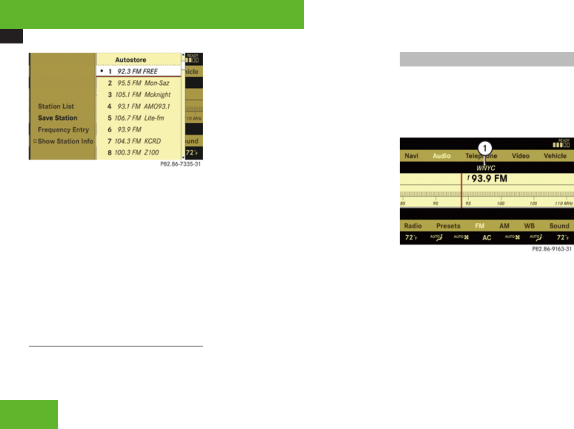
COMAND FM/AM radio
192
XSelecting a preset position: Slide qmr or
rotate ymz.
Saving a station to a selected preset
position
If you have called up the station preset screen
using option 1:
XPress n briefly.
In options 2 and 3:
XPress and hold n until you hear a signal.
The station is saved.
Saving using the autostore function
iThis function is not available for Weather
Band. The autostore function saves
receivable stations as presets in order of
their reception quality. All stations saved
manually in the preset memory will be lost
if COMAND finds 20 stations. If COMAND
finds less than 20 stations, for example 9,
then the stations saved in preset
positions 1 – 9 will be over written.
Option 1
XPress n when the main area is selected.
XSelect Autostore.
Option 2
XSelect Audio £ Audio £ FM/AM
Radio £ FM or AM.
XSelect Presets £ Autostore.
Option 3
XSelect Audio £ Audio £ FM/AM
Radio £ Radio £ Save Station £
Autostore.
Station name display
iIn the FM wave band, COMAND can show
the name of the station currently tuned in.
Station name display 1 can only be seen
when it is switched on and if the station
transmits a name.
1Station name display
XSwitching the station name display on/
off: Select Audio £ Audio £ FM/AM
Radio £ FM £ Radio £ Show
Station Info.
The display is switched on or off, depending
on the previous setting. When the display
is switched on, a checkmark appears in
front of the Show Station Info menu
item.
Control systems
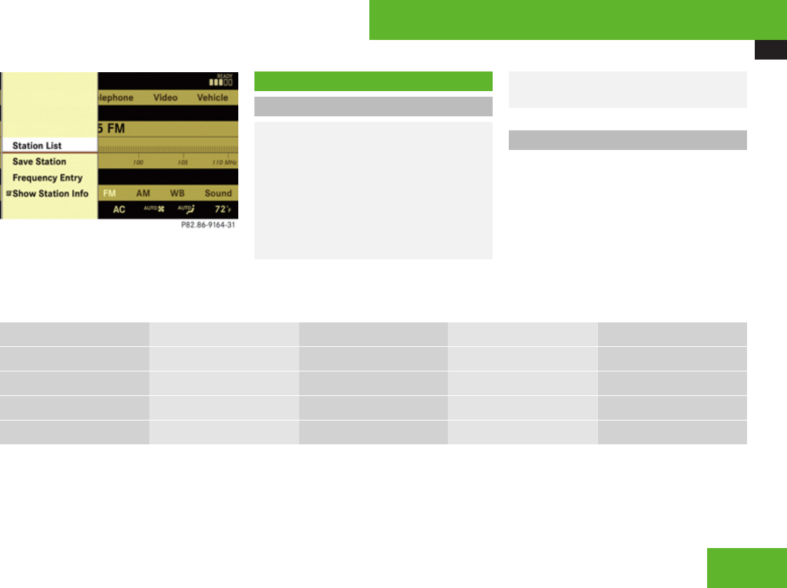
COMAND satellite radio
193
COMAND satellite radio
Safety notes
GWarning!
Please devote your attention first and
foremost to the traffic situation you are in.
Before your journey, please familiarize
yourself with the radio functions.
Only use the COMAND when road and
traffic conditions permit you to do so.
Otherwise you could be involved in an
accident in which you or others could be
injured.
Submenu overview
iThe components and operating principles
of COMAND can be found on (Y page 82).
Sat Radio Presets Info Category Sound
Channel List Station presets Showing program info Selecting category Treble
Save Channel Bass
Channel Entry Balance/Fader
Service 3D Sound
Control systems
Z

COMAND satellite radio
194
Introduction to satellite radio
iA subscription to SIRIUS Satellite Radio
service provider is required for the satellite
radio operation described in this section.
Contact an authorized Mercedes-Benz
Center for details and availability for your
vehicle.
SIRIUS Satellite Radio provides over
130 channels of digital-quality radio,
including 100% commercial-free music,
sports, news and entertainment. SIRIUS
Satellite Radio uses a fleet of high-power
satellites to broadcast 24 hours per day,
coast to coast, in the contiguous U. S. and
Canada.
This diverse, satellite-delivered programming
is available for a monthly subscription fee.
For more information and service availability
call the SIRIUS Service Center at
1-888-539-7474, or contact
Rwww.sirius.com (USA)
Rwww.siriuscanada.com (Canada)
iSatellite radio service may be unavailable
or interrupted from time to time for a
variety of reasons, such as environmental
or topographic conditions and other things
we cannot control. Service might also not
be available in certain places (e. g., in
tunnels, parking garages, under leafy trees,
or within or next to buildings) or near other
technologies. In such situations, the
satellite radio’s main menu shows the
Acquiring signal... screen. At this
point, the radio’s functions are restricted.
Switching to satellite radio
XSelect Audio £ Audio £ Sat Radio.
or
XPress the M shortcut button once or
twice. The Satellite radio menu appears if
it was the last active radio mode.
The screen which then appears depends on
the activation status of the satellite radio
service.
The following conditions are possible:
RSatellite radio service is not activated
(only the preview channel is displayed).
RSatellite radio service is activated.
Satellite radio service is not activated
The telephone number of the SIRIUS Service
Center and the twelve-digit electronic serial
number (SIRIUS-ID) of the particular receiver
are displayed.
This information is required when calling the
SIRIUS Service Center for an activation
request.
iActivating the satellite radio service might
not be available in certain places (e. g., in
tunnels, parking garages, under leafy trees,
or within or next to buildings). If a
subscription is not included with system
purchase, credit card information is
required to activate your account.
The activation process takes
approximately 5 to 10 minutes after calling
the SIRIUS Service Center.
iIt is also possible to activate the satellite
radio service online. To do so please visit
SIRIUS Satellite Radio’s website at
Control systems
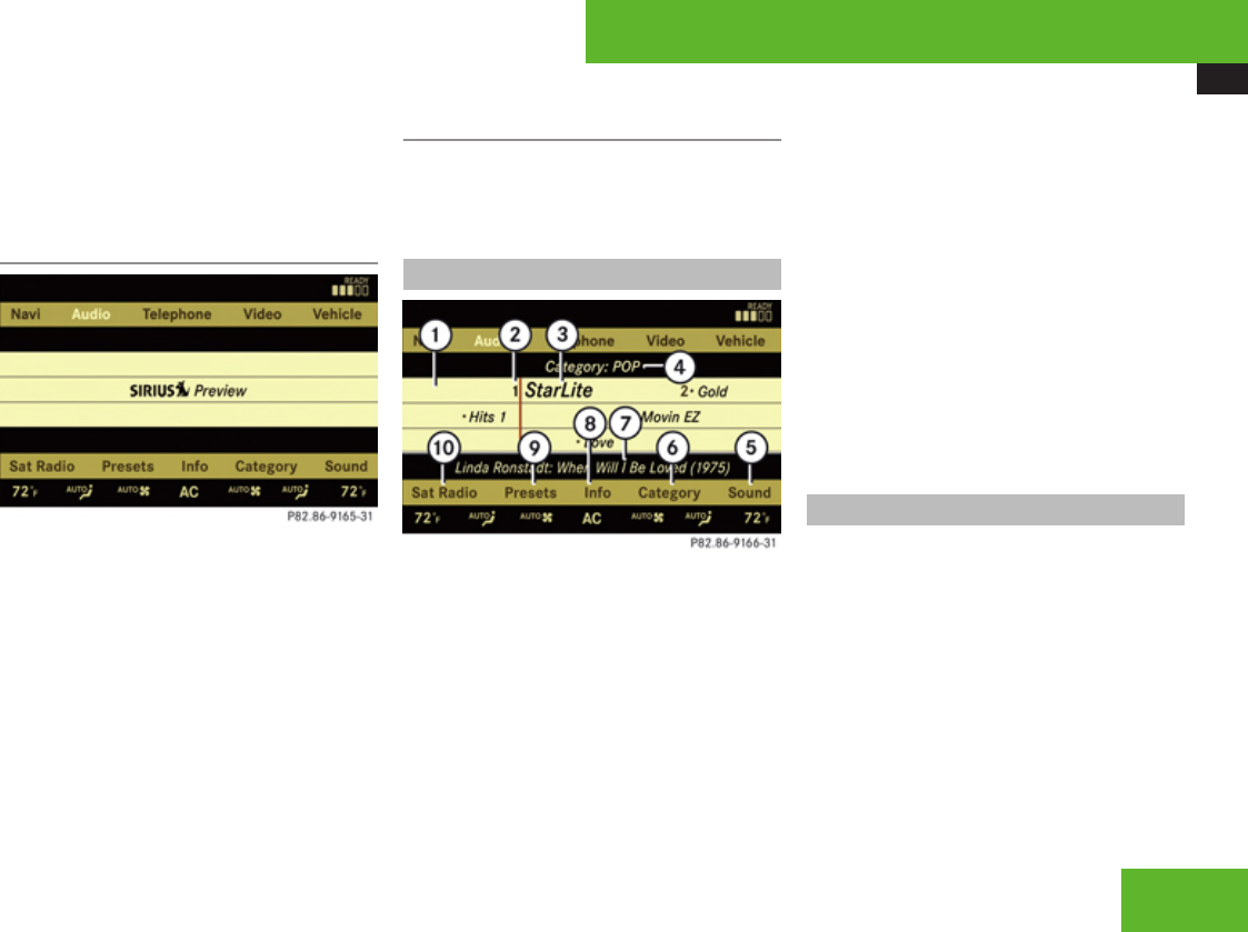
COMAND satellite radio
195
www.sirius.com (USA) or
www.siriuscanada.com (Canada).
XClosing screen: Press n.
Preview channel
iIf the satellite radio service has not been
subscribed to, only the preview channel is
available. You cannot tune in another
channel. If you try to do this, you will see
the screen described in the section
“Satellite radio service is not
activated” (Y page 194).
Satellite radio service is activated
The main satellite radio menu appears. You
will hear the channel last tuned in, provided
that it can be received.
Main satellite radio menu
1Main area with channel display
2Preset position of selected channel
3Selected channel
4Selected program category
5Sound settings
6To select program category
7Artist and song title
8Other channel information
9Preset options
aSatellite radio options
iMain area 1 can show all channels
included in your subscription. Which
channels are shown depends on the
selected program category 4.
Note that categories and channels shown
in illustrations are dependent on
programming content delivered by the
service provider. Programming content is
subject to change.
Therefore, channel and categories shown
in illustrations and descriptions contained
in this manual may differ from the channels
and categories delivered by the service
provider.
Selecting program category
iThe channels are categorized. Categories
allow you to tune to stations broadcasting
a certain type of program.
Satellite radio channels are split up into
categories such as News, Sports, Rock, or
Country, if available.
XSelect Audio £ Audio £ Sat Radio
£ Category.
The category list appears.
Control systems
Z

COMAND satellite radio
196
XSelect category by rotating ymz or sliding
qmr and press n.
When selecting a channel using the
channel search function or the channel list,
you have access to the channels you
subscribe to and which are included in the
selected category.
iWhen you select the category All
Channels, you have access to all the
channels you subscribe to, regardless of
category, when you are tuning in a channel
using the channel search function or the
channel list.
Tuning in channels
You have the following selection options:
RThe channel search function
RThe channel presets
RThe manual channel number entry
RThe channel list
Tuning in channels using channel
search function
iIf you try to tune in a channel when the
satellite radio service is not activated, you
will see the screen described in the section
“Satellite radio service is not
activated” (Y page 194).
XSlide omp or rotate ymz when the main
area is selected.
Depending on the direction in which the
controller is being pressed or rotated, the
system searches upward or downward and
stops at the next receivable channel.
iWhich channels are found by the channel
search function depends on which
channels you have subscribed to and the
program category you have selected
(Y page 195).
Tuning in channels using channel
presets
XSelect Audio £ Audio £ Sat Radio
£ Presets.
or
XPress n when the main area is selected.
The preset menu appears. The dot R in
front of a preset position indicates that this
is the channel currently selected and being
listened to.
XSelect station preset and briefly press n.
or
XEnter a position number with the telephone
keypad using the A - 9 buttons
(Y page 85).
COMAND tunes in the corresponding
channel as long as it is included in your
subscription and is still available.
If the channel is not included in your
subscription, you will see the message
described in the section “Satellite radio
service is not activated” (Y page 194).
If the channel is no longer available, you will
see the message Invalid Channel.
XClosing message: Press n.
Control systems

COMAND satellite radio
197
Tuning in channels using manual
channel number entry
iIf you try to tune in a channel when the
satellite radio service is not activated, you
will see the screen described in the section
“Satellite radio service is not
activated” (Y page 194).
Entering the channel number using the
COMAND controller
XSelect Audio £ Audio £ Sat Radio
£ Sat Radio £ Channel Entry.
The menu for manual channel number entry
appears.
XExiting menu without making an entry:
Press L back button in the center
console (Y page 90).
XIncrease or decreasing number: Slide
qmr or rotate ymz.
XSelecting next number: Slide omp.
XConfirming channel entry: Press n.
Further operation depends on whether the
selected channel number is valid or if the
channel is included in your subscription.
Entering the channel number using the
telephone keypad
XPress > on the telephone keypad
(Y page 85).
XEnter channel number using the R -
9 buttons.
Further operation depends on whether the
selected channel number is valid or if the
channel is included in your subscription.
Channel number is valid and channel is
included in subscription
COMAND tunes in the channel entered.
Channel number is invalid
You will see the message Invalid
Channel.
XClosing message: Press n.
Channel number is valid but channel is not
included in subscription
You will see the screen described in the
section “Satellite radio service is not
activated” (Y page 194).
XClosing display: Press n.
Tuning in channels using the channel
list
XSelect Audio £ Audio £ Sat Radio
£ Sat Radio £ Channel List.
The channel list appears. The dot R in
front of a list entry indicates the currently
selected channel.
XSelect channel by rotating ymz or sliding
qmr and press n.
iThe contents of the channel list depends
on which channels are included in your
subscription and which program category
you have selected (Y page 195). If satellite
radio service is not activated, the channel
list contains only the preview channel.
Saving channels
iThere are 20 preset positions available.
Option 1
XSelect Audio £ Audio £ Sat Radio
£ Sat Radio £ Save Channel.
Control systems
Z

COMAND satellite radio
198
Option 2
XPress n when the main area is selected.
Option 3
XSelect Audio £ Audio £ Sat Radio
£ Presets.
All three of these will call up a preset menu.
The dot R in front of a preset position
indicates that this is the channel currently
selected and being listened to.
XSelecting a preset position: Slide qmr or
rotate ymz.
Saving a channel to a selected preset
position
If you have called up the channel preset
screen using option 1:
XPress n briefly.
In options 2 and 3:
XPress and hold n until you hear a signal.
The channel is saved.
Show program info
XSelect £ Audio £ Audio £ Sat
Radio £ Info.
iIf the program provider does not offer any
information, the Info menu item cannot be
selected.
You will see a screen that may contain the
following information:
RSelected program category
RSelected channel
RArtist of the track currently being played
RName of current track
iThe program provider determines what
information is displayed on the screen.
COMAND shows no more than two lines per
item of information. If an item of
information is too long, COMAND shortens
it.
XClosing screen: Slide omp or press n.
Channel update
The service provider may conduct a channel
update.
During the update, the message Updating
channels... will appear on the display. No
functions can be operated in satellite radio
mode during the update.
Calling SIRIUS Service Center
iIt may be necessary to call the SIRIUS
Service Center if, for example:
RYou want to cancel the subscription or
resubscribe at a later date.
RYou have forgotten to pay the bill.
RYou sell the vehicle.
Control systems

COMAND audio CD/audio DVD/MP3
199
XSelect £ Audio £ Audio £ Sat
Radio £ Sat Radio £ Service.
The telephone number of the SIRIUS
Service Center and the twelve-digit
electronic serial number (SIRIUS-ID) of the
particular receiver are displayed.
XClosing screen: Slide omp or press n.
COMAND audio CD/audio DVD/MP3
Safety notes
GWarning!
COMAND is classified as a Class 1 laser
product. You must not open the casing.
There is a risk of exposure to invisible laser
radiation if you open the casing, or if the
casing is faulty or damaged.
COMAND does not contain any parts that
you are able to maintain yourself. For safety
reasons, all maintenance work must be
carried out by qualified technicians.
GWarning!
Only carry out the following when the
vehicle is stationary:
RInserting a disc
REjecting a disc
There is a risk of accident by being
distracted from road and traffic conditions
if you load a CD/DVD while the vehicle is
in motion.
Bear in mind that at a speed of just 30 mph
(approximately 50 km/h), your vehicle is
covering a distance of 44 feet
(approximately 14 m) every second.
Notes about MP3 mode
Permissible media for MP3/WMA files
RCD-R and CD-RW
RDVD-R and DVD-RW
RPCMCIA card (Y page 204)
Permissible file systems
RISO9660/Joliet for CDs
RUDF for DVDs
RFAT16 or FAT32 for PCMCIA cards with
storage medium
Multisession CDs
For multisession CDs, the first session type
of the CD determines how COMAND will
process the CD.
For example, if the first session type is
according to the audio CD standard and the
second session type is according to the data
CD standard containing MP3/WMA tracks,
COMAND will treat the CD as a conventional
audio CD. This means that it is only possible
Control systems
Z

COMAND audio CD/audio DVD/MP3
200
to access the audio CD tracks. Access to the
MP3/WMA tracks is not possible.
Similarly, if the first session type is according
to the data CD standard containing MP3/
WMA tracks and the second session type is
according to the audio CD standard,
COMAND will treat the CD as a data CD. This
means that it is only possible to access the
MP3/WMA tracks. Access to the audio CD
tracks is not possible.
File structure on a disc
When you create an MP3/WMA disc, the
MP3/WMA tracks can be organized in
folders. A folder can also contain other
folders. A disc can contain a maximum of
255 folders. Each folder can contain a
maximum of 255 tracks and 255 folders. A
data medium may contain a maximum of 500
tracks.
Track and folder names
When you create an MP3/WMA disc, you can
assign names to the MP3/WMA tracks and
folders.
COMAND uses these names for the
corresponding display in MP3 mode. Empty
folders or folders which contain data other
than MP3/WMA tracks are not displayed by
COMAND.
If MP3/WMA files are saved in the root
directory itself (uppermost directory on
storage medium), the root directory will also
be treated as a folder. COMAND will then
show the name of the root directory as the
folder name.
You must observe the following when
assigning track names:
RTrack names must have at least one
character.
RTrack names must have the extension
“mp3” or “wma”.
RThere must be a period between the track
name and the extension.
Example of a correct track name:
Track1.mp3
COMAND is unable to recognize an MP3/
WMA track if:
Rthere is no period between the track title
and the extension
Rthere is no extension
iCOMAND does not support ID3 tags.
Compatible file systems and
compression methods
The following compression methods are
compatible:
RMP3
RWMA
iIf music files created using different
compression methods other than MP3 are
stored together on a disc, the loading
process may take longer.
Permissible MP3 formats
COMAND supports the MPEG1 Audio Layer 3
format.
iThis format is generally known as “MP3”.
Permissible bit and sampling rates
RFixed and variable bit rates up to
320 kbit/s
RSampling rates from 24 kHz to 48 kHz
iOnly use MP3 tracks with a bit rate of at
least 128 kbit/s and a sampling rate of at
least 44.1 kHz. Smaller rates can cause a
noticeable deterioration in sound quality.
Control systems

COMAND audio CD/audio DVD/MP3
201
This is especially the case if you have
activated the surround sound function.
WMA (Windows Media Audio)
Windows Media Audio (WMA) is an audio data
compression technology developed by
Microsoft.
The audio system supports the following
types of audio files:
Rfixed bit rates of 5 kBit/s up to
384 kBit/s
Rsampling rates from 8 kHz to 48 kHz
The audio system does not support the
following WMA files:
RDRM (Digital Rights Management) coded
files
Rvariable bit rates
RWMA Pro
R5.1 Surround
Notes on copyright
The music tracks that you create and play
back in the MP3 or WMA format are generally
subject to copyright protection in accordance
with the applicable international and national
regulations.
In many countries, reproductions are not
permitted without the prior consent of the
copyright holder, not even for private use.
Make sure that you know the applicable
copyright regulations and that you comply
with these.
If you own these rights yourself, e. g. for your
own compositions and recordings, or the
copyright holder has granted you permission,
these restrictions do not apply.
Notes about audio DVD operation
COMAND can playback commercially
available, prerecorded audio DVDs that bear
the following label. You will usually find the
label on the DVD booklet, the inlay, or the
DVD itself.
iAudio DVDs differ from recordable DVD-
R and DVD-RW discs.
Data on audio DVDs are stored either in
uncompressed format or in lossless
compressed format. The sound quality on
audio DVDs is therefore better than on
recordable DVDs that contain MP3 data
because the MP3 format uses a lossy type of
compression.
You cannot delete data from or record
additional data to commercially available,
prerecorded audio DVDs.
Please note the following information about
CDs/DVDs and pay special attention to the
notes on copied and/or self-written CDs/
DVDs.
Notes about CDs/DVDs
iAudio CDs with copy protection are not
compatible with the CD audio standard and
therefore may not be able to be played by
COMAND.
There may be playback problems when
playing copied discs.
There is a large variety of discs, disc-writing
software and writers available. This variety
means that there is no guarantee that the
system will be able to play discs that you
have written/copied yourself.
There may be playback problems if you use
CD-R or CD-RW type discs you have copied
yourself with a storage capacity of more
than 700 MB. These CDs are not
compatible with currently applicable
standards.
Control systems
Z

COMAND audio CD/audio DVD/MP3
202
! Do not affix stickers or labels to the discs.
These could peel away and damage
COMAND. COMAND is designed to hold
discs which comply with the IEC 60908
standard. You can therefore only use discs
with a maximum thickness of 1.3 mm.
If you insert thicker discs, e. g. those that
contain data on both sides (DVD on one
side and audio data on the other), they
cannot be ejected and can damage
COMAND.
Do not use CDs with a diameter of 8 cm.
Attempting to play discs with a diameter of
8 cm or playing such discs with an adapter
may cause damage COMAND.
Such damages are not covered by the
Mercedes-Benz Limited Warranty.
Only use round discs with a diameter of
12 cm.
Notes about handling CDs/DVDs
ROnly hold discs by the edge.
RHandle discs carefully to prevent playback
problems.
RAvoid getting scratches, fingerprints and
dust on discs.
RClean discs from time to time with a
commercially-available cleaning cloth. Do
not wipe them with a circular motion, but
only in straight lines from the center
outwards.
ROnly use a pen designed for such a purpose
to label discs.
RPlace discs back in their boxes after use.
RProtect discs from heat and direct sunlight.
Inserting CDs and DVDs
GObserve Safety notes, see
page 199.
iIf the CD/DVD has a printed side, this
must face upwards when the CD/DVD is
inserted. If neither side is printed, the side
to be played should face downwards.
Loading the CD/DVD changer
The CD/DVD changer can hold up to a total
of 6 audio CDs or DVDs.
1Disc slot
2Load button (all magazine trays)
3Magazine tray buttons 1 – 6
iEach magazine tray button 3 indicates
the status of the corresponding magazine
tray by means of an LED.
RLED off = magazine tray is empty
RLED constantly lit = magazine tray is
loaded
RLED flashes = CD/DVD changer
requesting disc to be loaded
Loading an individual magazine tray
XPress desired magazine tray button 3.
If a disc is loaded, it will be ejected.
XTake disc out of slot 1.
Control systems
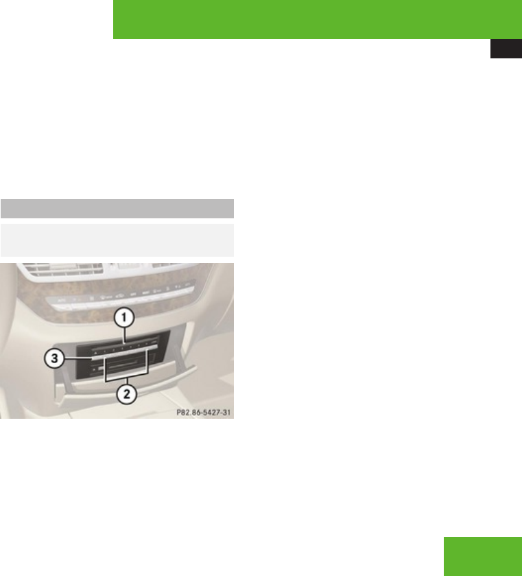
COMAND audio CD/audio DVD/MP3
203
XWait until LED for magazine tray button
3 which you pressed flashes quickly.
XInsert disc into slot 1.
The DVD changer draws the disc in and
begins playback if:
Rit has been loaded correctly
Rit is a permissible type of disc
Loading all six magazine trays
XPress load button 2.
The DVD changer checks the load status of
all magazine trays and switches to the first
empty tray.
XWait until LED for corresponding magazine
tray button 3 flashes quickly.
XInsert disc into slot 1.
The DVD changer switches to the next
empty magazine tray.
iIf a disc is not inserted within
approximately 15 seconds COMAND
resumes playback of the last disc.
XRepeat last two steps until all trays are
loaded.
The DVD changer will play the last disc you
have loaded if:
Rit has been loaded correctly
Rit is a permissible type of disc
Ejecting CDs and DVDs
GObserve Safety notes, see
page 199.
1Disc slot
2Magazine tray buttons 1 – 6
3Eject button (all discs)
iIf you eject one disc while playing another
disc, the DVD changer interrupts playback.
Playback continues once the disc has been
ejected.
XEjecting one disc: Press desired magazine
tray button 2.
XTake disc out of slot 1.
If you do not take the disc out of slot 1,
the DVD changer will draw it back
automatically in approximately
15 seconds.
XEjecting all discs: Press eject button 3.
The DVD changer switches to the first
loaded tray and ejects the disc.
XTake disc out of slot 1.
The DVD changer switches to the next
loaded magazine tray and ejects the disc.
XRepeat last step until magazine is empty.
Control systems
Z
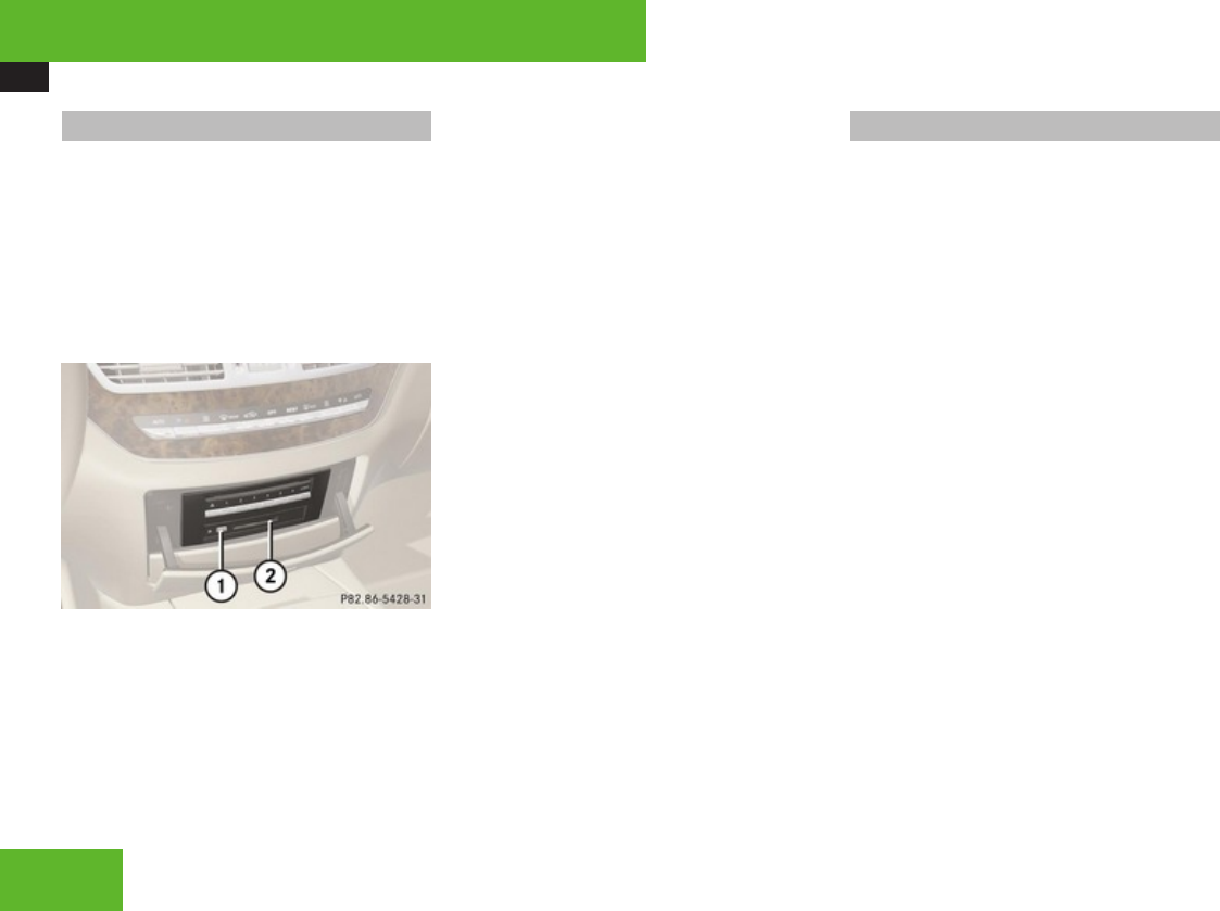
COMAND audio CD/audio DVD/MP3
204
Inserting/Ejecting a PCMCIA card
iCOMAND supports commercially
available PCMCIA cards or PCMCIA card
adapters with storage media that may not
be designed for the temperatures which
occur in the vehicle. You should therefore
remove the PCMCIA card from the vehicle
when not in use since extreme
temperatures could damage these devices.
1Eject button
2Slot for PCMCIA card
XInserting: Insert PCMCIA card into slot
2. The side with the contact must point
towards the slot.
If the PCMCIA card contains a storage
medium with MP3 tracks, COMAND
switches to MP3 mode.
XEjecting: Press eject button 1 twice.
The PCMCIA card is ejected.
XTake PCMCIA card out of slot 2.
Submenu overview
iThe components and operating principles
of COMAND can be found on (Y page 82).
Control systems

COMAND audio CD/audio DVD/MP3
205
CD or DVD-A or MP3 Pause/Stop/Play
(audio DVD mode
only)
Tracks/
Track List/
Tracks A-Z
Folders
(MP3 mode only)
Changer Sound
Normal Track
Sequence
Pausing playback Showing track list
(audio CD mode and
audio DVD mode)
Selecting folder Selecting medium Treble
Random Tracks Stopping playback Displaying
alphabetical track
listing (MP3 mode
only)
Bass
Random folder (MP3
mode only)
Restarting playback Balance/Fader
Repeat folder (MP3
mode only)
Group (DVD-Audio
mode only)
3D Sound
Control systems
Z
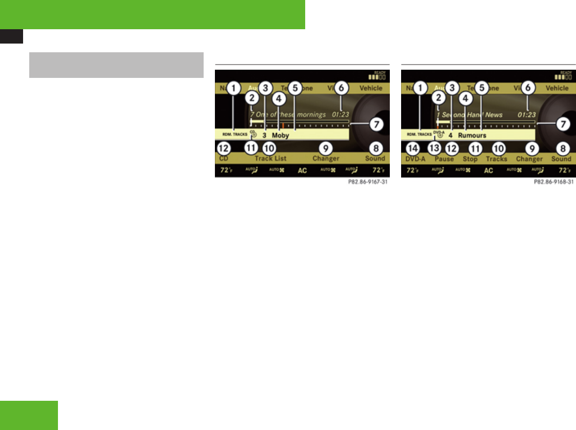
COMAND audio CD/audio DVD/MP3
206
Switching to audio CD, audio DVD or
MP3 mode
XLoad CD/DVD (Y page 202) or PCMCIA
card (Y page 204).
or
XSelect Audio £ Audio, then CD, DVD-
Audio or MP3.
or
XPress the M shortcut button once or
twice.
iThe M shortcut button takes you
directly to the previously set disc mode
(audio CD/DVD, MP3-CD/DVD, video DVD
or PCMCIA card). The number of times you
have to press the shortcut button depends
on the previously set mode.
Example display in audio CD mode
1Current playback option
2Track number
3Disc number
4Disc name (only if saved on the disc)
5Track name (only if saved on the disc)
6Track time
7Graphic time and track display
8Sound settings
9Medium selection
aTo call up track listing
bDisc type
cPlayback options
Example display in audio DVD mode
1Current playback option
2Track number
3Disc number
4Disc name (only if saved on the disc)
5Track name (only if saved on the disc)
6Track time
7Graphic time and track display
8Sound settings
9Medium selection
aTo call up track listing
bStop function
cPause (Play appears if paused)
dDisc type
ePlayback options
Control systems
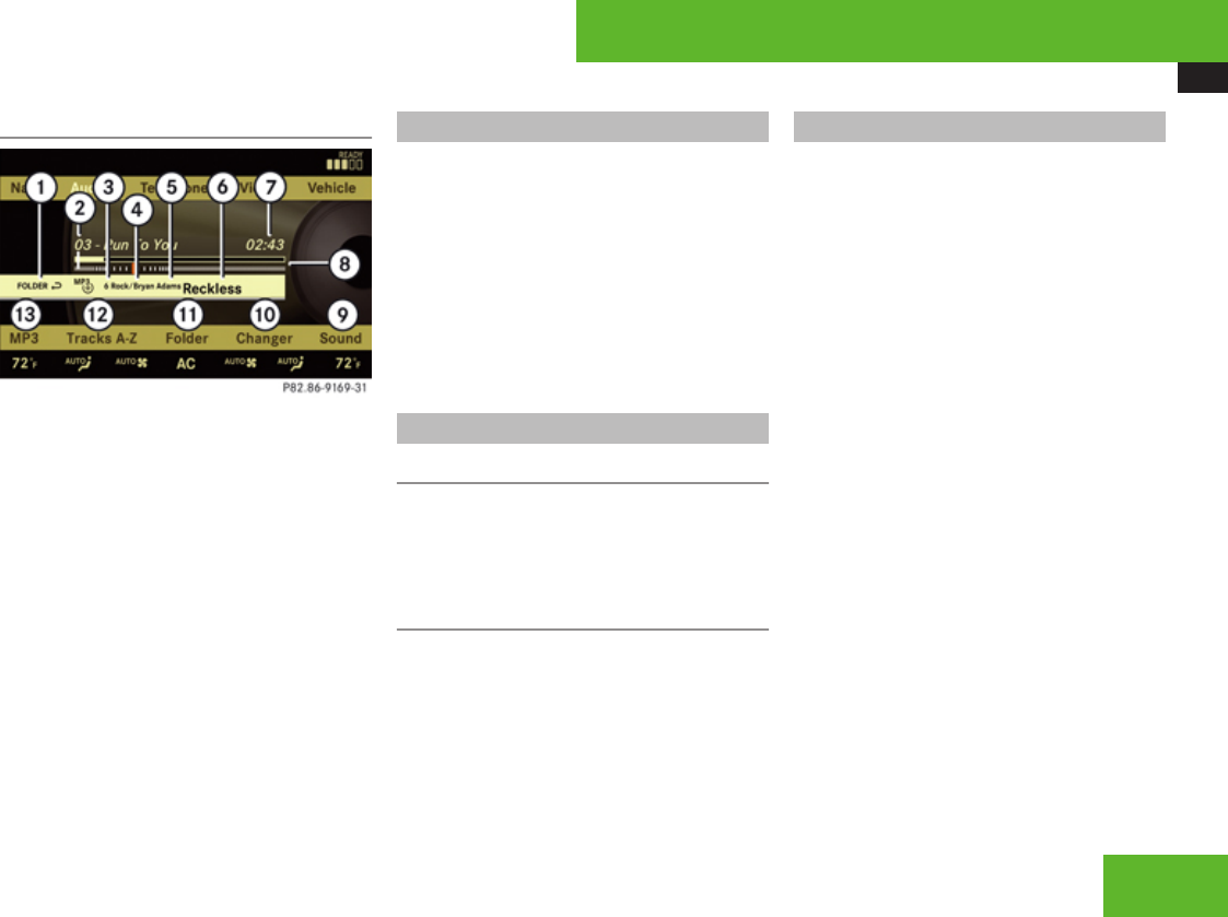
COMAND audio CD/audio DVD/MP3
207
Example display in MP3 mode
1Current playback option
2Medium type
3Disc number (not on PCMCIA card)
4Track name
5Current folder path
6Current folder
7Track time
8Graphic time and track display
9Sound settings
aMedium selection
bFolder listing
cTrack listing
dPlayback options
Stop function
iThis function is only available in audio
DVD mode.
XStopping playback: Select Audio £
Audio £ DVD-Audio £ Stop.
XRestarting playback: Select Audio £
Audio £ DVD-Audio £ Play.
Playback starts at the beginning of the
DVD.
Pause function
In audio CD, audio DVD and MP3 mode
XPausing playback: Press F briefly.
XContinuing playback: Press F again
briefly.
Only in audio DVD mode
XPausing playback: Select Audio £
Audio £ DVD-Audio £ Pause.
The Pause screen changes to Play.
XContinuing playback: Select Audio £
Audio £ DVD-Audio £ Play.
The Play screen changes to Pause.
Selecting CD/DVD/MP3 media
XSelect Audio £ Audio.
XSelect CD, DVD-Audio or MP3.
COMAND begins playback.
XIn audio CD, audio DVD and MP3
mode: Select Changer.
or
XIn audio CD and audio DVD mode only:
Press n when the main area is selected.
The media list appears. The dot R
indicates the current medium.
XSelect a medium or folder.
COMAND changes the medium.
or
XEnter a magazine tray number with the
telephone keypad using the A - 9
buttons (Y page 85).
Control systems
Z

COMAND audio CD/audio DVD/MP3
208
Selecting a track
Selecting by skipping to tracks
XSkipping forwards or backwards to a
track (in CD or DVD mode only): Rotate
ymz.
iSkipping forwards through the tracks
skips to the next track. Skipping backwards
through the tracks skips to the beginning
of the current track if the track has been
playing for more than 8 seconds.
If the track has been playing for less than
8 seconds, it skips to the start of the
previous track.
If you have switched on the Random
Tracks playback option, the order of the
tracks is random.
Selecting from the track list
XSelect Audio £ Audio.
XSelect CD, DVD-Audio or MP3.
Selecting a track using the COMAND
controller
XSelect Tracks, Tracks A-Z or Track
list.
or
XOnly in MP3 mode: Press n when the
main area is selected.
The track list of the current folder appears.
The dot R indicates the current track.
XSelect a track by rotating ymz or sliding
qmr.
iIn MP3 mode, the list shows all the tracks
in alphabetical order.
Selecting a track using the telephone
keypad
XPress > on the telephone keypad
(Y page 85).
XEnter track number using the A - 9
buttons.
Fast forward/rewind
XSelect main area.
XSlide and hold omp until desired place is
reached.
Selecting a folder
iThis function is only available in audio
MP3 mode.
XSelect Audio £ Audio £ MP3 £
Folder.
or
XPress n when main area is selected.
The track list of the current folder appears.
Control systems
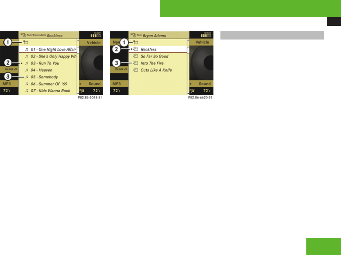
COMAND audio CD/audio DVD/MP3
209
1Back folder symbol
2Current track symbol
3Track symbol
XMove to the superordinate folder: Select
the Q symbol.
The display changes to the next folder up
in the folder structure on the disc.
1Back folder symbol
2Current folder symbol
3Folder symbol containing tracks
XSelecting a folder: Select desired folder.
You will see the tracks in the folder.
XSelect a track.
The track is played and the corresponding
folder is now the active folder.
Setting the audio format
This function lets you choose the audio
format that you would like COMAND to play
and is only available in DVD-Audio mode.
iThe tracks on an audio DVD can be stored
in various audio formats. The number of
audio formats depends on the audio DVD.
XSelect Audio £ Audio £ DVD-Audio
£ Group.
iThe Group menu item cannot be selected
if only one audio format is saved on the
DVD.
The list of available audio formats appears. A
dot R indicates the format currently
selected.
XChanging setting: Slide qmr or rotate
ymz.
XExiting menu: Slide omp.
Control systems
Z

COMAND AUX
210
Playback options
The following options are available:
RNormal Track Sequence
Tracks playback in the order on the disc
(e. g. track 1, 2, 3, etc.).
RRandom Tracks
Tracks playback in a random order (e. g.
track 3, 8, 5, etc.).
RRandom Folder (in MP3 mode only)
Tracks in the active folder and any
subfolders playback in random order.
RRepeat Folder (in MP3 mode only)
Tracks in the active folder will be repeated
until you switch the function off.
XSelecting an option: Select Audio £
Audio.
XSelect CD, DVD-Audio or MP3.
The option list appears. A dot R indicates
which option is switched on.
XSelect an option and press n.
The option is switched on. For all options
except Normal Track Sequence, you will
see a corresponding indicator in the main
area.
iThe Normal Track Sequence option is
automatically activated when you select a
different medium. If an option is activated,
it remains activated after COMAND is
switched on/off.
COMAND AUX
You can connect an external audio or video
source (AUX) to COMAND.
Audio and Video AUX socket
The Audio and Video AUX-jacks to which
external audio/video sources can be
connected are located in the glove box.
1Video AUX jack
2Audio AUX jack
Control systems

COMAND AUX
211
Audio AUX
Switching to Audio AUX mode
XSelect Audio £ Audio £ AUX.
The Audio AUX menu appears. You will hear
the medium in the external audio source if
it has been connected and switched to
play.
iPlease refer to the corresponding
operating instructions for information
about how to operate the external audio
source.
You can adjust the following settings in Audio
AUX mode:
RVolume (Y page 92)
RBalance and fader (Y page 93)
RTreble and bass (Y page 93)
RSurround sound (Y page 93)
GWarning
Due to the different volumes of the external
audio sources, system messages (e.g.
navigation announcements) may be much
louder. You may need to disable these
system messages or adjust the volume of
these messages manually.
iThe volume of external audio sources is
extremely variable. It is possible that a
device connected as an external audio
source will sound quieter or louder in the
vehicle or that the usual maximum volume
cannot be achieved. On certain devices the
volume can be set separately. In this case
start at a moderate volume and increase it
slowly. In this way you can determine
whether the system is capable of playback
without distortion, even at high volume.
Video AUX
Automatic picture fade-out
If a video is playing when the vehicle is shifted
from park position P into neutral position N,
drive position D or reverse gear R the picture
is faded out automatically and the following
message appears in the display: In order
not to distract driver, picture is
faded out while the vehicle is in
motion.
When the vehicle is shifted back into park
position P, the picture comes on again.
Switching to Video AUX mode
XSelect Video £ Video £ AUX.
The Video AUX menu appears. You will see
the medium in the external audio source if
it has been connected and switched to
play.
Control systems
Z
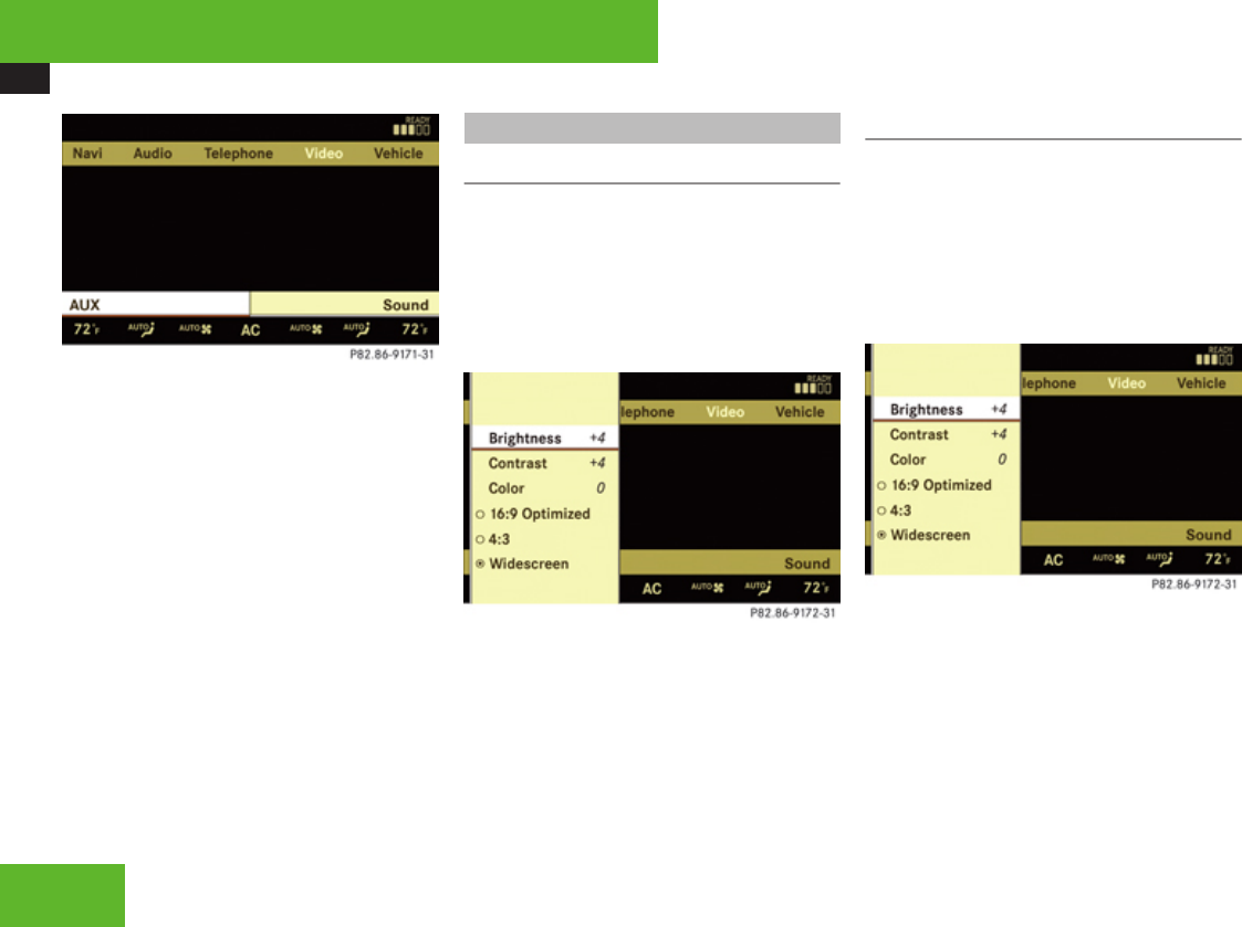
COMAND AUX
212
iPlease refer to the corresponding
operating instructions for information
about how to operate the external video
source.
You can adjust the following settings in Video
AUX mode:
RScreen settings (Y page 212)
RVolume (Y page 92)
RBalance and fader (Y page 93)
RTreble and bass (Y page 93)
RSurround sound (Y page 93)
Screen settings
Setting brightness, contrast and color
XShow the menu system, if necessary
(Y page 215).
XSelect Video £ AUX £ AUX.
The menu appears.
XSelect a setting: Slide qmr or turn ymz.
XPress n.
XChanging settings: Slide qmr or turn
ymz until you reach the desired setting.
XSaving settings: Press n.
Changing the picture format
XShow the menu system, if necessary
(Y page 215).
XSelect Video £ AUX £ AUX.
The DVD-V menu appears. The dot R in
front of a menu item - 16:9 Optimized,
4:3 or Widescreen indicates the current
format.
XChanging the format: Slide qmr or turn
ymz, until you reach the desired setting.
XSaving the format: Press n.
Control systems

COMAND video DVD
213
COMAND video DVD
Safety notes
GObserve Safety notes, see
page 199.
Automatic picture fade-out
If a video DVD is playing when the vehicle is
shifted from park position P into neutral
position N, drive position D or reverse gear
R the picture is faded out automatically and
the following message appears in the display:
In order not to distract driver,
picture is faded out while the
vehicle is in motion.
When the vehicle is shifted back into park
position P, the picture comes on again.
Notes about video DVD operation
COMAND can playback commercially
available, prerecorded video DVDs that bear
the following label. You will usually find the
label on the DVD booklet, the inlay, or the
DVD itself.
iVideo DVDs differ from recordable DVD-
R and DVD-RW discs.
iThere may be playback problems when
playing copied DVDs.
There is a large variety of discs, disc-writing
software and writers available. This variety
means that there is no guarantee that the
system will be able to play discs that you
have written/copied yourself.
Some DVDs may not comply with the NTSC
or PAL TV playback standards. Sound, picture
and other playback problems may occur
when you play such DVDs.
COMAND can playback video DVDs meeting
the following requirements:
RCorrect regional code
RNTSC or PAL TV standard
The appropriate information is usually given
either on the DVD or the DVD box. The factory
setting of COMAND is regional code 1. The
setting can be changed at an authorized
Mercedes-Benz Center. This will allow you to
playback video DVDs with other regional
codes, as long as they comply with the NTSC
or PAL TV standard.
Notes about DVDs
! Do not affix stickers or labels to the discs.
These could peel away and damage
COMAND. COMAND is designed to hold
discs which comply with the IEC 60908
standard. You can therefore only use discs
with a maximum thickness of 1.3 mm.
If you insert thicker discs, e. g. those that
contain data on both sides (DVD on one
side and audio data on the other), they
cannot be ejected and can damage
COMAND.
Control systems
Z

COMAND video DVD
214
Do not use CDs with a diameter of 8 cm.
Attempting to play discs with a diameter of
8 cm or playing such discs with an adapter
may cause damage COMAND.
Such damages are not covered by the
Mercedes-Benz Limited Warranty.
Only use round discs with a diameter of
12 cm.
Notes about handling DVDs
For notes about handling DVDs, see
(Y page 202).
Functional limitations
Depending on the DVD, it is possible that
certain functions or actions may be
temporarily or permanently unavailable. If
you try to utilize such functions or carry out
such actions, you will see the 7 symbol in
the display.
Inserting or ejecting DVDs
GObserve Safety notes, see
page 202.
XInserting a DVD (Y page 202).
or
XEjecting a DVD (Y page 203).
Submenu overview of video DVD
DVD-V Pause/Play Stop Changer Sound
DVD Functions Pausing playback Pausing Playback Selecting medium Treble
Brightness Continuing playback Stopping playback Bass
Contrast Restarting playback Balance/Fader
Color 3D Sound
16:9 Optimized
Control systems
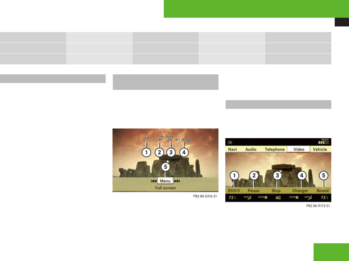
COMAND video DVD
215
DVD-V Pause/Play Stop Changer Sound
4:3
Widescreen
Switching to video DVD mode
XInsert a DVD (Y page 202).
or
XSelect Video £ Video £ Video DVD.
or
XPress the M shortcut button once or
twice.
iThe M shortcut button takes you
directly to the previously set disc mode
(audio CD/DVD, MP3-CD/DVD or video
DVD). The number of times you have to
press the shortcut button depends on the
previously set mode.
Hiding/showing the DVD control
menu
XHiding the menu: Slide qmr.
XShowing the menu: Slide qmr.
or
XWait for approximately 8 seconds.
Control menu
1Disc type
2Current track
3Current scene
4Elapsed track time
5Show the menu system
Hiding/showing the menu system
XShowing the menu: Press n.
XHiding the menu: Press n when the main
menu area is selected.
Menu system
1Video DVD options
2Pause
Control systems
Z

COMAND video DVD
216
3Stop
4Medium selection
5Sound settings
Fast forward/rewind
XSlide omp and hold until you get to the
desired scene.
Selecting the DVD medium
XSelect Video £ Video £ Video DVD.
XShow the menu system, if necessary
(Y page 215).
XSelect Changer.
The media list appears. The dot R
indicates the current medium.
XSelect a medium.
COMAND changes the medium.
Stop playback
XSelect Video £ Video £ Video DVD.
XShow the menu system, if necessary
(Y page 215).
XStop play: Select Stop.
In the display, Pause changes to Play.
XContinue playback: Select Play.
Play is continued from the point at which it
was stopped.
XStop playback: Select Stop again while
playback is stopped.
or
XSelect Stop twice in quick succession
during playback.
XResume playback: Select Play.
Playbacks starts again from the beginning.
Pause playback
XSelect Video £ Video £ Video DVD.
XShow the menu system, if necessary
(Y page 215).
XPause playback: Select Pause.
In the display, Pause changes to Play.
XContinue playback: Select Play.
Play is continued from the point at which it
was stopped.
Selecting scene/chapter
Entering scene/chapter using the
COMAND controller
XMake sure that the control menu is shown
(Y page 215).
XSkipping forwards or back: Slide omp or
turn ymz.
Control systems

COMAND video DVD
217
Entering the scene/chapter using the
telephone keypad
XPress > on the telephone keypad
(Y page 85).
XEnter scene/chapter using the A -
9 buttons.
COMAND tunes in to the scene/chapter
entered.
Selecting film/track
iThis function is only available if the DVD
is comprised of several film/tracks.
XSelect Video £ Video £ Video DVD.
XShow the menu system, if necessary
(Y page 215).
XSelect DVD-V £ DVD Functions £
Title selection.
A selection list appears.
XSelect a film/track.
Screen settings
Setting brightness, contrast and color
XSelect Video £ Video £ Video DVD.
XShow the menu system, if necessary
(Y page 215).
XSelect DVD-V £ Brightness £
Contrast or Color.
XChanging settings: Slide qmr or turn
ymz until you reach the desired setting.
XSaving settings: Press n.
Changing the picture format
XSelect Video £ Video £ Video DVD.
XShow the menu system, if necessary
(Y page 215).
XSelect DVD-V.
The DVD-V menu appears. The dot R in
front of a menu item - 16:9 Optimized,
4:3 or Widescreen indicates the current
format.
XChanging the format: Slide qmr or turn
ymz, until you reach the desired setting.
XSaving the format: Press n.
DVD menu
The DVD menu is the menu stored on the DVD
itself. It is structured in various ways
according to the individual DVD and permits
certain actions and settings.
Calling up the DVD menu
XSelect Video £ Video £ Video DVD.
XShow the menu system, if necessary
(Y page 215).
XSelect DVD-V £ DVD Functions £
Menu.
The DVD menu appears.
Selecting menu items in the DVD menu
XSlide qmr or omp.
XConfirming the selection: Press n.
The selection menu appears.
Control systems
Z
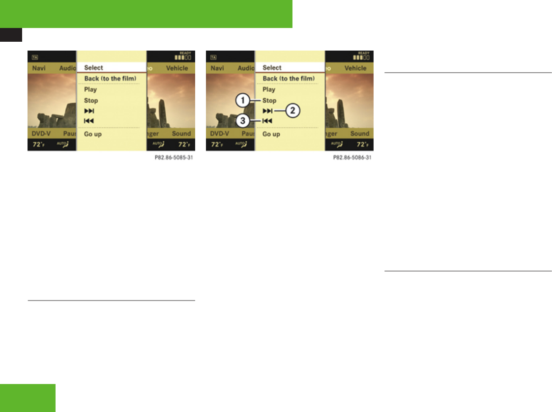
COMAND video DVD
218
XReconfirming the selection: Select
Select.
COMAND carries out the action defined by
the selected DVD menu item.
iDepending on the DVD, it is possible the
menu item Play either has no function or
has no function in certain parts of the DVD
menu.
Stopping the film or skipping to the
beginning/end of a scene
XSelect a menu item of your choice from the
DVD menu.
The selection menu appears.
1Stop film
2Skip to the end of a scene
3Skip to the beginning of a scene
XStopping the film: Select Stop.
XSkipping to the end of a scene: Select
H.
XSkipping to the beginning of a scene:
Select G.
iDepending on the DVD, it is possible the
menu items H and G either have no
function or have no function in certain parts
of the DVD menu.
Switching to the next highest DVD
menu level
XPress the L back button in the center
console.
or
XSelect the corresponding menu item in the
DVD menu.
or
XSelect a menu item of your choice from the
DVD menu.
XSelect the menu item Go up in the selection
menu.
iDepending on the DVD, it is possible the
menu item Go up either has no function or
has no function in certain parts of the DVD
menu.
Back to the film
XPress the L back button until you can
see the film.
or
XSelect the corresponding menu item in the
DVD menu.
or
XSelect a menu item of your choice from the
DVD menu.
Control systems

COMAND video DVD
219
XSelect the menu item Back (to the
film) in the selection menu.
iDepending on the DVD, it is possible the
menu item Back (to the film) either
has no function or has no function in certain
parts of the DVD menu.
Setting the language and audio
format
iThis function is not available for all DVDs.
If it is available, you can set the language
for the DVD menu and the audio language
and/or the audio format. The number of
settings you can make is determined by the
content of the DVD. It may also be possible
to make the settings in the DVD menu
(Y page 217).
XSelect Video £ Video £ Video DVD.
XShow the menu system, if necessary
(Y page 215).
XSelect DVD-V £ DVD Functions.
XSelect Menu Language or Audio
Language.
In both cases a selection list will appear.
The dot R in front of an entry indicates the
current language.
XChanging the setting: Slide qmr or turn
ymz, until you reach the desired setting.
XSaving a setting: Press n.
XExiting the menu: Slide omp.
Subtitles and camera angles
iThis function is not available for all DVDs.
The number of settings you can make is
determined by the content of the DVD. It
may also be possible to make the settings
in the DVD menu (Y page 217).
XSelect Video £ Video £ Video DVD.
XShow the menu system, if necessary
(Y page 215).
XSelect DVD-V £ DVD Functions.
XSelect Subtitles or Camera angle.
In both cases a selection list will appear.
The dot R in front of an entry indicates the
current language.
XChanging the setting: Slide qmr or turn
ymz, until you reach the desired setting.
XSaving a setting: Press n.
XExiting the menu: Slide omp.
Interactive content
iDVDs may include interactive content
(e. g. a video game). In a video game you
can control the play by selecting and
initiating actions. The type and number of
actions depends on the DVD.
XSelecting an action: Slide qmr or omp,
or turn ymz, until you reach the desired
setting.
XInitiating an action: Press n.
A menu appears, the first entry Select is
highlighted.
XPress n.
Control systems
Z
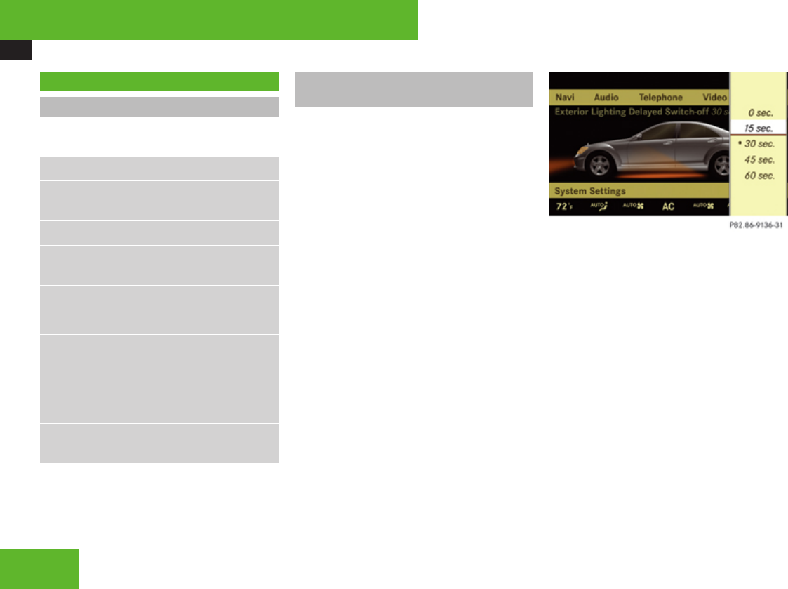
COMAND vehicle menu
220
COMAND vehicle menu
Introduction
In this menu, you can program the following
vehicle functions:
Function
Exterior Lighting Delayed Switch-off
(Y page 220)
Locator Lighting (Y page 221)
Exterior Mirror Convenience Settings
(Y page 222)
Automatic Locking (Y page 222)
Easy Entry/Exit Feature (Y page 223)
Interior Ambient Light (Y page 224)
Interior Lighting Delayed Switch-off
(Y page 224)
Rear-window Sunshade (Y page 225)
Trunk Opening-height Restriction
(Y page 226)
Setting night security illumination
(Exterior Lighting Delayed Switch-off)
iThe components and operating principles
of COMAND can be found on (Y page 82).
Use this function to set whether and how long
you would like the exterior lighting to
illuminate during darkness after exiting the
vehicle and all doors closed.
The exterior lighting automatically goes out
after the delayed switch-off time has expired.
You can select:
R0 sec., the delayed switch-off feature is
deactivated
R15 sec., 30 sec., 45 sec., or 60 sec.,
the delayed switch-off feature is activated
iYou can reactivate this function within
10 minutes by opening a door.
XSelect Vehicle.
The main area is active.
XSelecting Exterior Lighting Delayed
Switch-off menu: Slide omp or rotate
ymz.
XConfirming selection: Press n.
XSelecting length of time: Slide qmr or
rotate ymz.
XConfirming selection: Press n.
or
XSelect Vehicle £ Vehicle £
Exterior Lighting Delayed Switch-
off.
A selection list appears.
The current setting is indicated by a
dot R.
Control systems
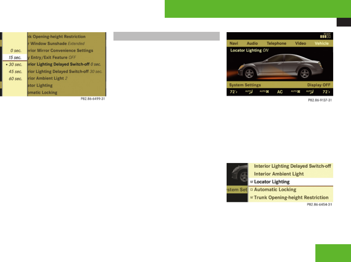
COMAND vehicle menu
221
XSelecting length of time: Slide qmr or
rotate ymz.
XConfirming selection: Press n.
To activate night security illumination:
XSelect delayed switch-off period (see
above).
XTurn the exterior lamp switch to position
* before turning off the engine.
Locator lighting on/off
iThe components and operating principles
of COMAND can be found on (Y page 82).
With the locator lighting feature activated and
the exterior lamp switch in position *
(Y page 325), the following lamps will switch
on during darkness when the vehicle is
unlocked from the outside:
RParking lamps
RTail lamps
RLicense plate lamps
RFront fog lamps
RDoor entry lamps in the mirror
RSide marker lamps
The locator lighting switches off when the
driver’s door is opened.
If you do not open a door after unlocking the
vehicle with the SmartKey, the lamps will
switch off automatically after approximately
40 seconds.
XSelect Vehicle.
The main area is active.
XSelecting Locator Lighting function:
Slide omp or rotate ymz.
XConfirming selection: Press n.
XSwitching locator lighting on or off:
Press n.
or
XSelect Vehicle £ Vehicle £ Locator
Lighting.
A checkmark appears when the locator
lighting is enabled.
XConfirming selection: Press n.
Control systems
Z
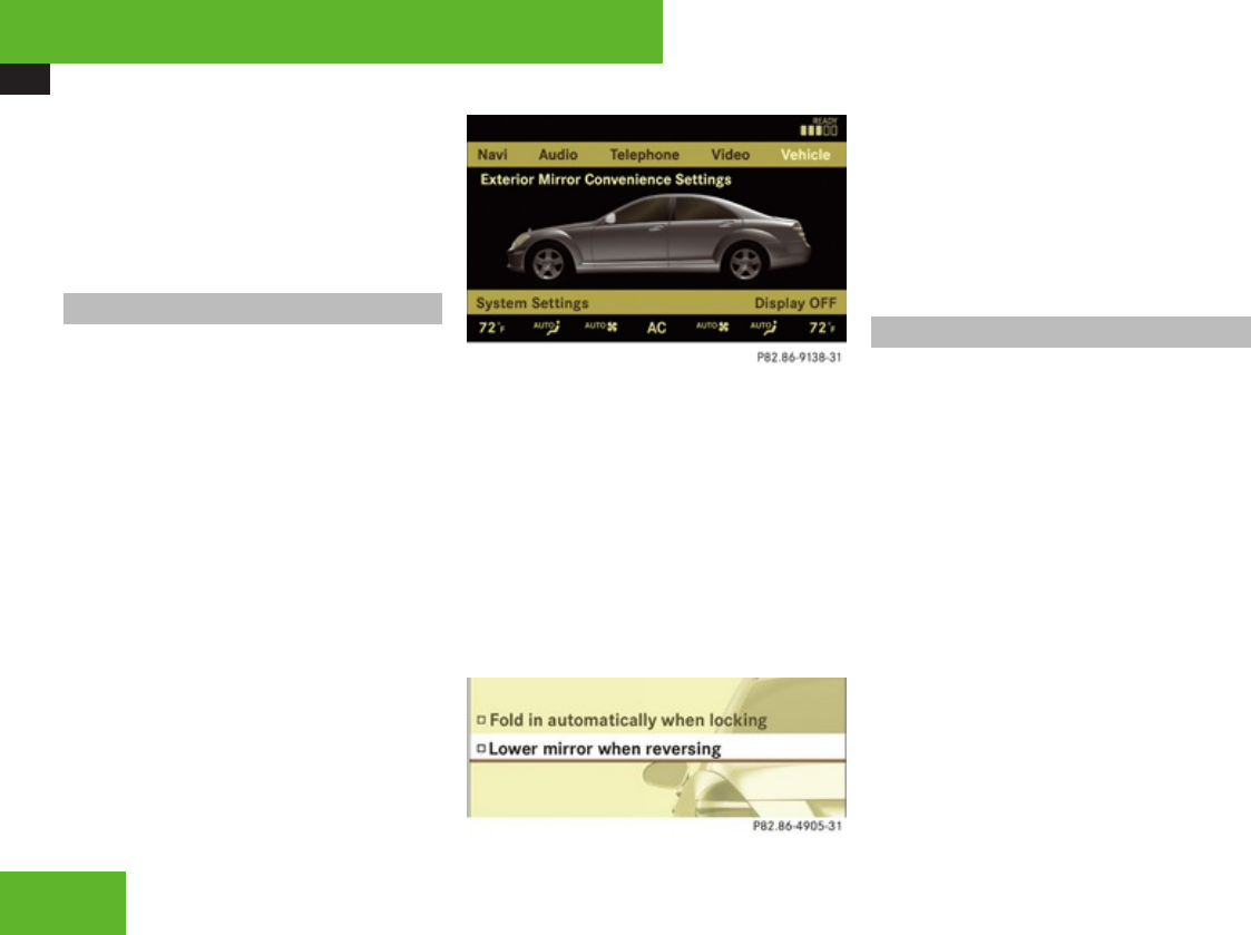
COMAND vehicle menu
222
To activate locator lighting:
XMake sure the function Locator
Lighting is set.
XTurn the exterior lamp switch to position
* when exiting the vehicle.
Exterior mirror convenience settings
iThe components and operating principles
of COMAND can be found on (Y page 82).
In the Exterior Mirror Convenience
Settings menu, you can switch the following
exterior rear view mirror functions on or off:
RExterior rear view mirrors automatically
fold in when the vehicle is locked.
RExterior rear view mirror on front passenger
side automatically tilts downward when the
vehicle is reversing.
XSelect Vehicle.
The main area is active.
XSelecting Exterior Mirror
Convenience Settings menu: Slide
omp or rotate ymz.
XConfirming selection: Press n.
XSelecting Fold in automatically when
locking or Lower mirror when
reversing: Rotate ymz.
XConfirming selection: Press n.
XSlide omp to exit.
or
XSelect Vehicle £ Vehicle £
Exterior mirror Convenience
Settings.
A selection list appears.
XSelecting a function: Slide qmr or rotate
ymz.
A checkmark appears in the corresponding
box when the option has been selected.
XConfirming selection: Press n.
XSlide omp to exit.
Automatic locking on/off
iThe components and operating principles
of COMAND can be found on (Y page 82).
Use this function to activate or deactivate the
automatic central locking (Y page 301). With
the automatic central locking system
activated, the vehicle is centrally locked at
vehicle speeds of approximately 9 mph
(15 km/h).
XSelect Vehicle.
The main area is active.
XSelecting Automatic Locking function:
Slide omp or rotate ymz.
Control systems
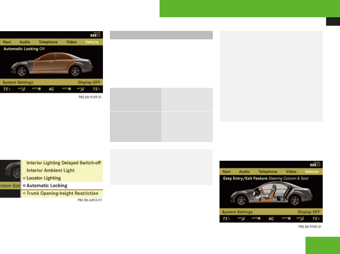
COMAND vehicle menu
223
XSwitching automatic locking on or off:
Press n.
or
XSelect Vehicle £ Vehicle £
Automatic Locking.
A checkmark appears when automatic
locking is switched on.
XConfirming selection: Press n.
XSlide omp to exit.
Activating easy-entry/exit feature
iThe components and operating principles
of COMAND can be found on (Y page 82).
Use this function to activate and deactivate
the easy-entry/exit feature (Y page 313).
The following settings are available for the
easy-entry/exit feature:
OFF The easy-entry/exit
feature is
deactivated.
Steering Column
& Seat
Both the steering
column and the
driver’s seat are
moved.
GWarning!
You must make sure no one can become
trapped or injured by the moving steering
wheel and driver’s seat when the easy-
entry/exit feature is activated.
To stop seat/steering wheel movement, do
one of the following:
RPress seat adjustment switch
RMove steering wheel adjustment stalk
RPress one of the memory position
buttons or the memory button M
Do not leave children unattended in the
vehicle, or with access to an unlocked
vehicle. Children could open the driver’s
door and unintentionally activate the easy-
entry/exit feature, which could result in an
accident and/or serious personal injury.
XSelect Vehicle.
The main area is active.
XSelecting Easy Entry/Exit Feature
menu: Slide omp or rotate ymz.
Control systems
Z
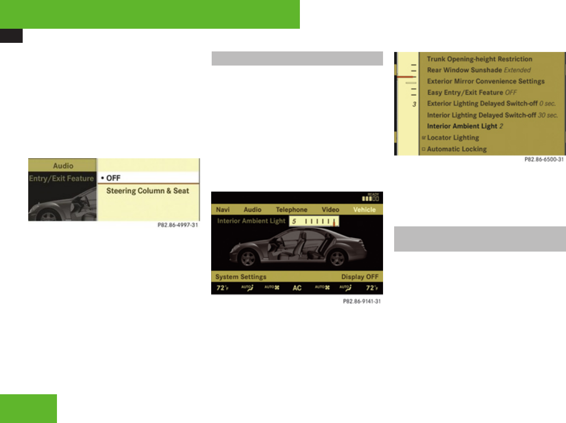
COMAND vehicle menu
224
XConfirming selection: Press n.
or
XSelect Vehicle £ Vehicle £ Easy
Entry/Exit Feature.
XConfirming selection: Press n.
A selection list appears.
The current setting is indicated by a
dot R.
XSelecting a setting: Slide qmr or rotate
ymz.
XConfirming selection: Press n.
Setting interior ambient lighting
iThe components and operating principles
of COMAND can be found on (Y page 82).
You can adjust the brightness of the interior
lighting on a scale of 0 (off) to 5 (bright).
XSelect Vehicle.
The main area is active.
XSelecting Interior Ambient Light
menu: Slide omp or rotate ymz.
XConfirming selection: Press n.
XAdjusting brightness: Slide omp or
rotate ymz.
XConfirming selection: Press n.
or
XSelect Vehicle £ Vehicle £
Interior Ambient Light.
XAdjusting brightness: Slide qmr or
rotate ymz.
XConfirming selection: Press n.
Setting interior lighting delayed
switch-off
iThe components and operating principles
of COMAND can be found on (Y page 82).
Use this function to set whether and how long
you would like the interior lighting to remain
lit during darkness after you have removed
the SmartKey from the starter switch.
Control systems
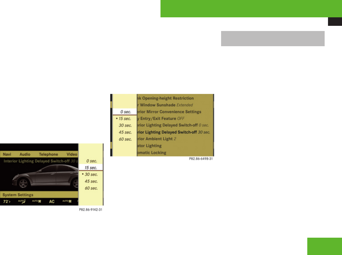
COMAND vehicle menu
225
You can select:
R0 sec., the delayed switch-off feature is
deactivated
R15 sec., 30 sec., 45 sec., or 60 sec.,
the delayed switch-off feature is activated
XSelect Vehicle.
The main area is active.
XSelecting Interior Lighting Delayed
Switch-off menu: Slide omp or rotate
ymz.
XConfirming selection: Press n.
A selection list appears.
The current setting is indicated by a
dot R.
XSelecting length of time: Slide qmr or
rotate ymz.
XConfirming selection: Press n.
or
XSelect Vehicle £ Vehicle £
Interior Lighting Delayed Switch-
off.
A selection list appears.
The current setting is indicated by a
dot R.
XSelecting length of time: Slide qmr or
rotate ymz.
XConfirming selection: Press n.
Extending or retracting rear window
sunshade
iThe components and operating principles
of COMAND can be found on (Y page 82).
This function is used to extend or retract the
rear sunshade.
iIf you operate the rear window sunshade
via COMAND or by using the favorite button
(Y page 98), this takes precedence over the
buttons for the rear window sunshade in
the rear doors (Y page 421).
iYou can program this function using the
favorite button (Y page 98).
iAt temperatures below -4‡ (-20†), the
rear window sunshade is switched off.
XSelect Vehicle.
The main area is active.
XSelecting Rear-window Sunshade
function: Slide omp or rotate ymz.
Control systems
Z
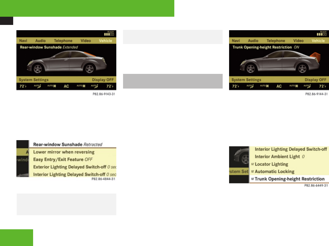
COMAND vehicle menu
226
XExtending or retracting rear window
sunshade: Press n.
or
XSelect Vehicle £ Vehicle £ Rear-
window Sunshade.
XConfirming selection: Press n.
GWarning!
When operating the rear window sunshade,
be sure that there is no danger of anyone
being harmed by the extending or
retracting procedure.
XReverse the extending or retracting
procedure: Press n again.
Trunk opening-height restriction on/
off
iThe components and operating principles
of COMAND can be found on (Y page 82).
Vehicles with trunk opening/closing system:
You can select whether the trunk lid should
open fully or only to the height of the roof.
XSelect Vehicle.
The main area is active.
XSelecting Trunk Opening-height
Restriction function: Slide omp or
rotate ymz.
XConfirming selection: Press n.
XSwitching on or off: Press n.
or
XSelect Vehicle £ Vehicle £ Trunk
Opening-height Restriction.
A checkmark appears when the trunk
opening-height restriction is switched on.
XConfirming selection: Press n.
Control systems
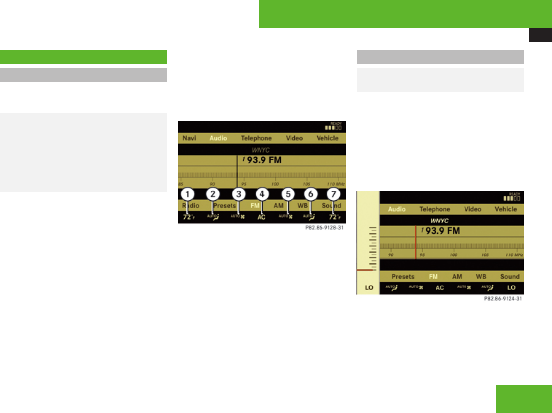
COMAND automatic climate control
227
COMAND automatic climate control
Introduction
iThe components and operating principles
of COMAND can be found on (Y page 82).
GWarning!
Follow the recommended settings for
heating and cooling given on the following
pages and pages in the “Controls in detail”
chapter. Otherwise the windows could fog
up, impairing visibility and endangering you
and others.
You can operate the climate control via
COMAND or via the buttons on the climate
control panel (Y page 395).
Some of the special climate control functions
can only be operated via COMAND.
The following climate control functions can
be operated via COMAND:
RTemperature (Y page 227)
RAir distribution (Y page 228)
RAir volume (Y page 228)
RSwitching off cooling (+)
(Y page 229)
RCentral climate control (Mono)
(Y page 230)
RFootwell temperature (Y page 230)
RAir flow from air vents (Y page 230)
RRear climate control (Y page 231)
The climate control menu is called up via the
climate control settings.
Climate control settings with functions (submenus)
1Temperature, driver’s side
2Air distribution, driver’s side
3Air volume, driver’s side
4Central menu, climate control
5Air volume, passenger side
6Air distribution, passenger side
7Temperature, passenger side
Setting temperature
GObserve Safety notes, see
page 397.
Use the temperature controls ®
(Y page 395) in the center console or
COMAND climate control settings to
separately adjust the air temperature on each
side of the passenger compartment.
XSelect climate control settings £
Temperature, left or right and then press
n.
Control systems
Z
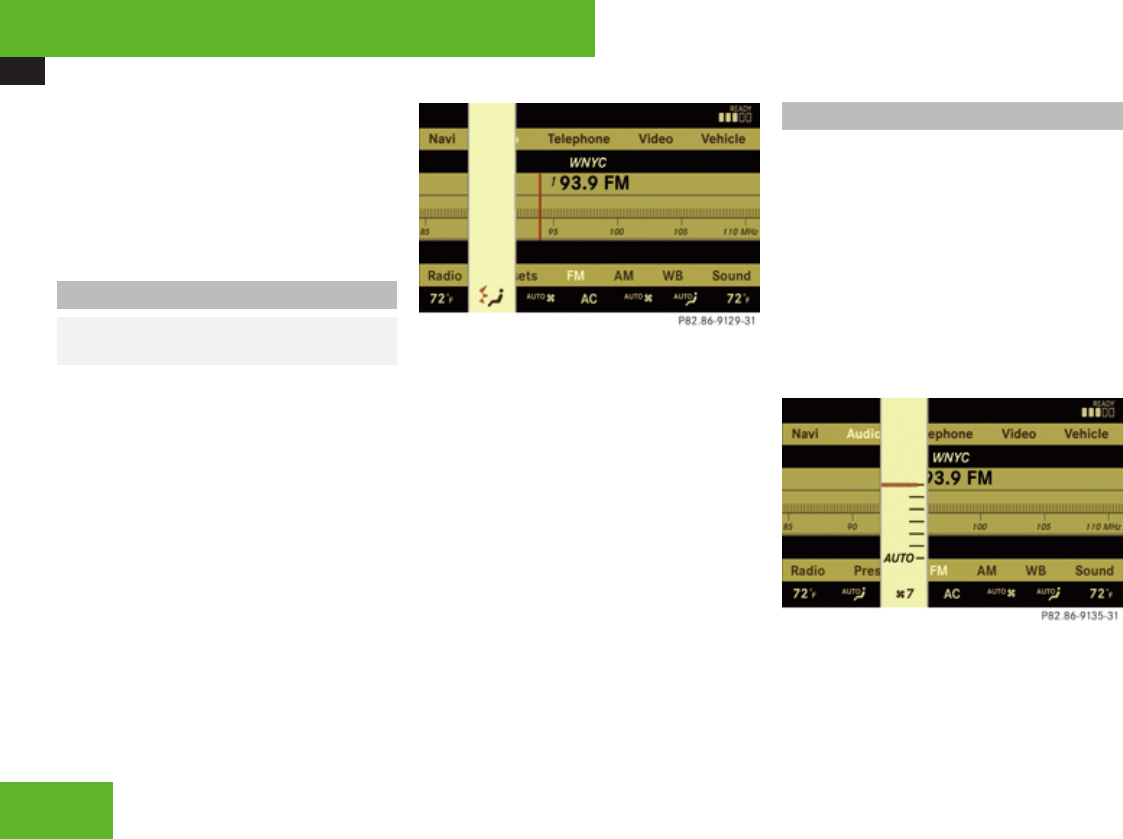
COMAND automatic climate control
228
XChanging temperature: Slide qmr or
rotate ymz.
XExiting menu: Press n, back button
L in the center console (Y page 83) or
slide omp.
The setting is saved.
Adjusting air distribution
GObserve Safety notes, see
page 397.
You can adjust the air distribution separately
for the driver’s and front passenger side.
iWhen you change the air distribution, the
automatic function of the climate control
system is switched off.
XSelect climate control settings £ Air
distribution, driver’s side or passenger
side.
XChanging air distribution: Rotate ymz.
The symbol for air distribution changes. The
direction and size of the arrows represent
the air distribution.
or
XSwitching back to automatic mode:
Rotate ymz and select AUTO.
XExiting menu: Press n, back button
L in the center console (Y page 83) or
slide omp.
The setting is saved.
Adjusting air volume
Use rocker switches Q (Y page 395) in
the center console or COMAND climate
control settings to separately adjust the air
volume on each side of the passenger
compartment.
iWhen you change the air volume, the
automatic function of the climate control
system is switched off.
XSelect climate control settings £ Air
volume, driver’s side or passenger side.
XChanging air volume: Slide qmr or rotate
ymz.
or
XSwitching back to automatic mode:
Rotate ymz and select AUTO.
Control systems
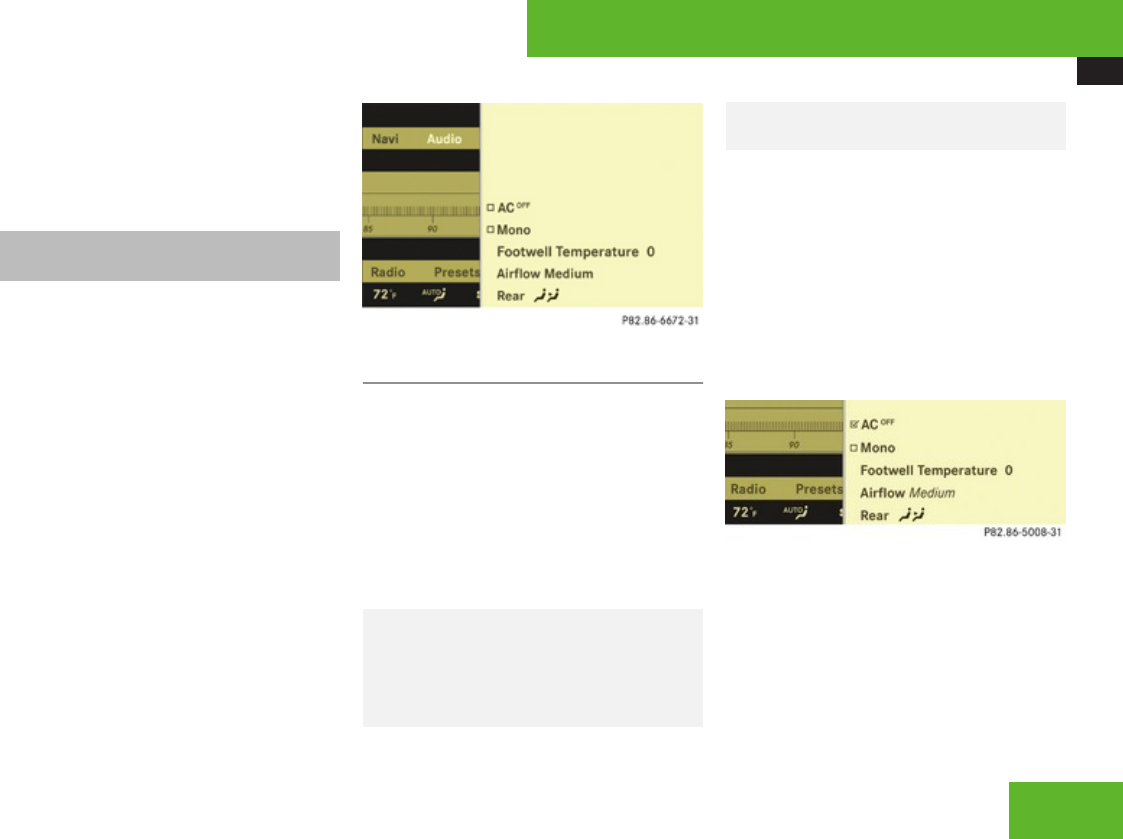
COMAND automatic climate control
229
XExiting menu: Press n, back button
L in the center console (Y page 83) or
slide omp.
The setting is saved.
Central climate control menu via
COMAND
The central climate control menu is in the
center of the climate control settings. When
the climate control is switched on, you will
see AC in the central menu. The following
functions can only be operated in the central
climate control menu via COMAND:
RSwitching off cooling (+)
(Y page 229)
RCentral climate control (Mono)
(Y page 230)
RFootwell temperature (Y page 230)
RAir flow from air vents (Y page 230)
XSelect climate control settings £ Central
menu.
Switching cooling on or off
The cooling function, only operational when
the engine is running, cools the vehicle
interior down to the selected temperature.
The cooling function also dehumidifies the air
in the vehicle interior, thus preventing the
windows from fogging up.
iCondensation may drip out from
underneath the vehicle. This is normal and
not an indication of a malfunction.
GWarning!
If you switch off the cooling function, the
vehicle will not be cooled when weather
conditions are warm. The windows can fog
up more quickly. Window fogging may
impair visibility and endanger you and
others.
XSelect climate control settings £ Central
climate control menu.
XSelecting +: Slide qmr or rotate
ymz.
XConfirming selection: Press n.
A checkmark appears when the cooling is
switched off.
+ appears in the central menu of the
climate control settings.
! If the air conditioning cannot be activated
again, this indicates that the air
conditioning is losing refrigerant. The
compressor has turned off.
Have the air conditioning checked at the
nearest authorized Mercedes-Benz Center.
Control systems
Z
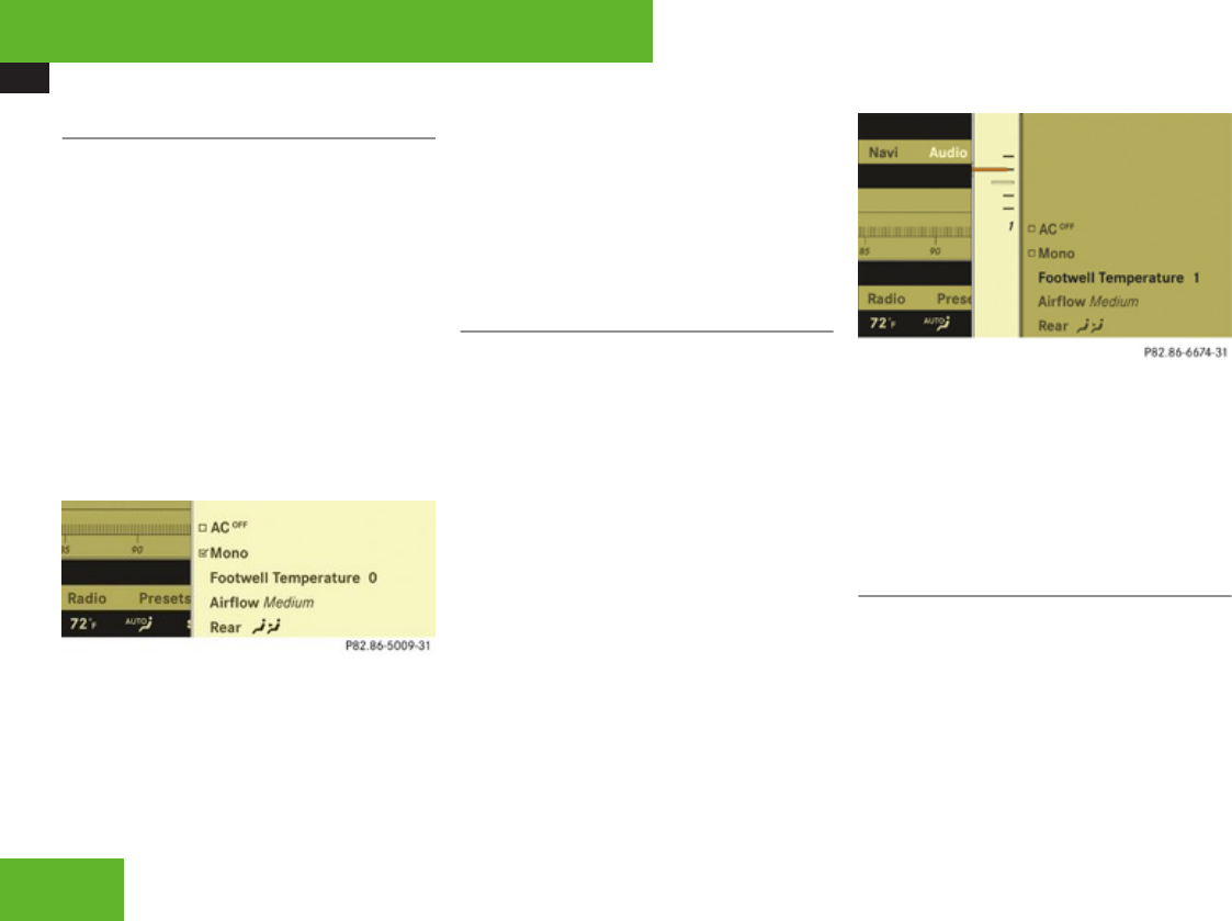
COMAND automatic climate control
230
Selecting Mono mode
Mono is used to adjust the climate zones for
the entire vehicle at the same time. When the
Mono function is switched on and you change
the climate on the driver’s side, these
changes will be carried out in the same
manner for all climate zones.
XSelect climate control settings £ Central
climate control menu.
XSelecting Mono: Slide qmr or rotate
ymz.
XConfirming selection: Press n.
A checkmark appears when the function
has been selected.
XExiting menu: Press back button L in
the center console (Y page 83) or slide
omp.
The Mono function is automatically switched
off when you:
Rchange an climate control setting for the
front passenger side using COMAND
Roperate a button from the climate control
for the front passenger side
Roperate one of the buttons for the rear
climate control system
Adjusting footwell temperature
iIn automatic mode, this setting optimizes
the footwell temperature when outside
temperatures are low.
The Footwell Temperature function is used
to adjust the temperature difference between
the footwell and the rest of the passenger
compartment.
The higher the selected value, the higher the
temperature in the footwell will be.
XSelect climate control settings £ Central
climate control menu.
XSelecting Footwell Temperature: Slide
qmr or rotate ymz and then press n.
XChanging temperature difference: Slide
qmr or rotate ymz.
XExiting menu: Press n, back button
L in the center console (Y page 83) or
slide omp.
The setting is saved.
Adjusting air flow from air vents
iIn automatic mode, this setting optimizes
the air flow when outside temperatures are
high.
The Airflow setting defines air distribution
and air volume in automatic mode:
Control systems
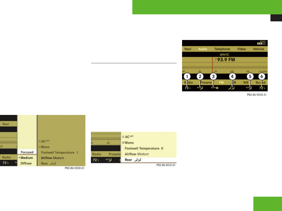
COMAND automatic climate control
231
RFocused (default setting, increased air
flow)
RMedium (reduced air flow)
RDiffuse (minimal air flow)
iWhen the interior ambient temperature of
the vehicle is very hot and the climate
control is cooling the interior, the setting
for air flow is temporarily overridden.
XSelect climate control settings £ Central
climate control menu £ Airflow.
A selection list appears.
The current setting is indicated by a
dot R.
XChanging air flow: Slide qmr or rotate
ymz.
XConfirming selection: Press n.
Operating rear climate control from the
front
The Rear) function is used to operate the
rear climate control via COMAND and the
rocker switches on the control panel from the
front (Y page 395).
Switching on rear climate control
operation from the front
XSelect climate control settings £ Central
climate control menu.
XSelecting Rear): Slide qmr or rotate
ymz.
XConfirming selection: Press n.
In the climate control setting, )
appears in the central menu. The rear
climate control can be operated from the
front.
Climate control settings, rear climate control
1Rear temperature, left
2Rear air distribution, left
3Rear air volume
4Central menu for rear climate control
5Rear air distribution, right
6Rear temperature, right
The rear climate control is operated in the
same manner as the climate control system
for the driver’s and front passenger side.
Central menu for rear climate control
In the central menu for the rear climate
control, you can:
Control systems
Z
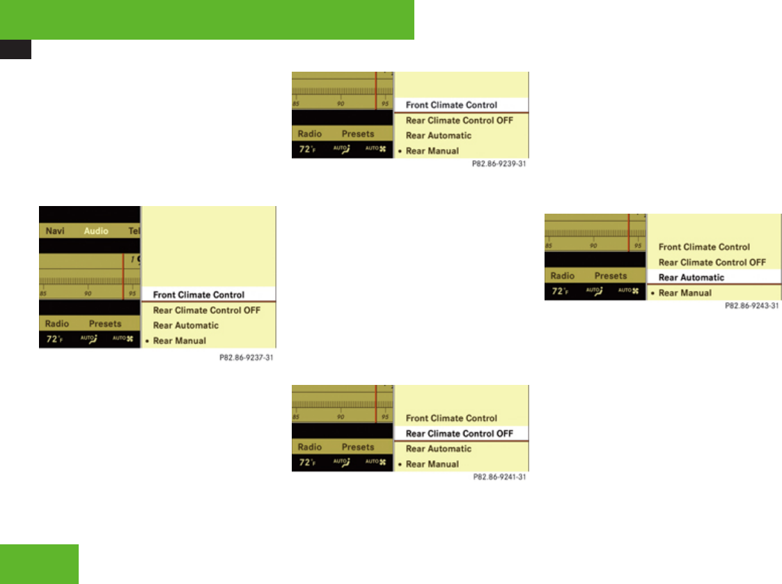
COMAND automatic climate control
232
Rswitch back to operating the front climate
control system
Rswitch off the rear climate control
Rswitch the automatic function of the rear
climate control from automatic to manual
XSelect climate control settings £ Central
climate control menu.
Switching off rear climate control
operation from the front
XSelect climate control settings £ Central
climate control menu.
The current setting is indicated by a
dot R.
XSelecting Front Climate Control: Slide
qmr or rotate ymz.
XConfirming selection: Press n.
The climate control settings shows the
climate control settings for the driver and
front passenger.
Switching off rear climate control
XSelect climate control settings £ Central
climate control menu.
The current setting is indicated by a
dot R.
XSelecting Rear Climate Control OFF:
Slide qmr or rotate ymz.
XConfirming selection: Press n.
The rear climate control is switched off.
Switching on the automatic function of
the rear climate control
XSelect climate control settings £ Central
climate control menu.
The current setting is indicated by a
dot R.
XSelecting Rear Automatic: Slide qmr or
rotate ymz.
XConfirming selection: Press n.
The automatic function of the rear climate
control is switched on.
Control systems
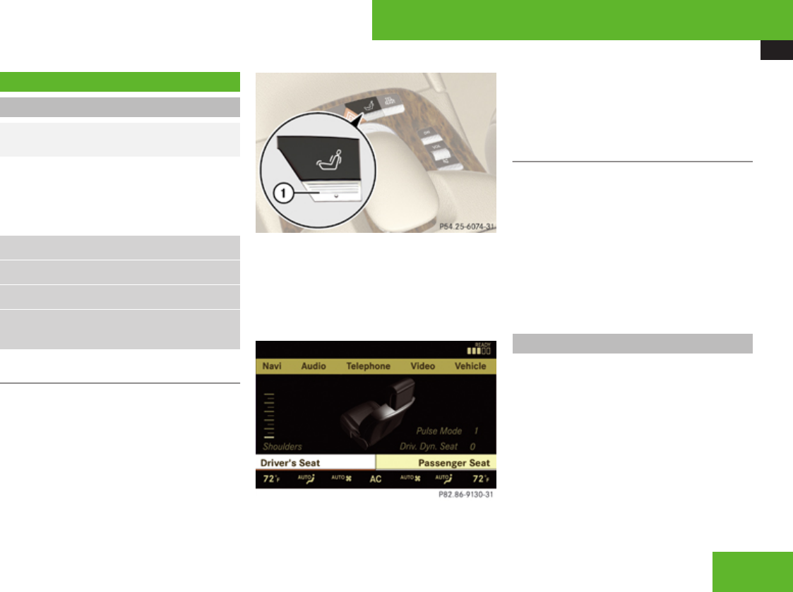
COMAND seats
233
COMAND seats
Operating seats via COMAND
GObserve Safety notes, see
page 309.
iThe components and operating principles
of COMAND can be found on (Y page 83).
The following seat adjustments can be made
via COMAND:
Settings
Lumbar support (Y page 233)
Multicontour seats, front (Y page 234)
Drive-dynamic multicontour seats, front
(Y page 236)
Selecting a seat
You must first select the seat for which you
would like to make adjustments.
1Seat menu button
XPress button O.
The main area is active.
XSwitching to the bottom menu line: Slide
qmr.
Example illustration: Drive-dynamic multicontour
seat
XSelecting seat: Slide omp or rotate
ymz.
XConfirming selection: Press n.
Exiting menu
There are several ways to exit the
multicontour seat menu.
XPress button O again.
or
XPress any shortcut button.
or
XSelect another main function from the main
menu line.
Lumbar support
To support the spine, you can adjust the
curvature of the front seat backrests.
XPress O.
The main area of the COMAND display is
active. A scale appears.
Control systems
Z
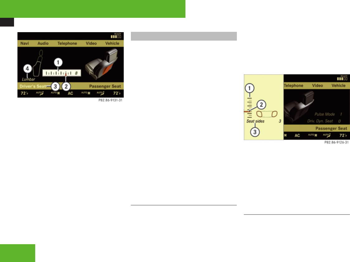
COMAND seats
234
1Scale
2Cursor
3Current seat
4Current setting
XSelect seat (Y page 233).
XAdjusting lumbar support: Slide omp or
rotate ymz until desired setting is
reached.
XConfirming selection: Press n.
XSwitching to the bottom menu line: Slide
omp.
XConfirming selection: Press n.
iAfter you have pressed O, the seat last
adjusted is active.
Multicontour seats, front
iIf PRE-SAFE® has been activated, the air
pressure in the air chambers (on the sides
of the seat cushion and seat backrest) of
the front multicontour seats is increased.
iWhen you adjust the multicontour seat,
noises may result from pumping air into or
releasing air out of the air chambers.
To support the spine, you can individually
adjust the seat backrest contour of the front
seats by regulating the air pressure in the air
chambers of the multicontour seat.
You can adjust the following air chambers:
Rsides of seat cushion
Rsides of seat backrest
Rseat backrest curvature in lumbar area
Rseat backrest curvature in shoulder area
The settings are made on the COMAND
display.
Adjusting sides of seat cushion
This function is used to adjust the air
chambers in the sides of the seat cushion.
XSelect seat (Y page 233).
XSelecting Seat sides: Slide omp or
rotate ymz.
XConfirming selection: Press n.
A scale appears.
1Scale
2Cursor
3Current setting
XSlide qmr or rotate ymz until desired
setting is reached.
XSaving setting: Press n.
Adjusting seat backrest sides
This function is used to adjust the air
chambers in the seat backrest sides.
Control systems
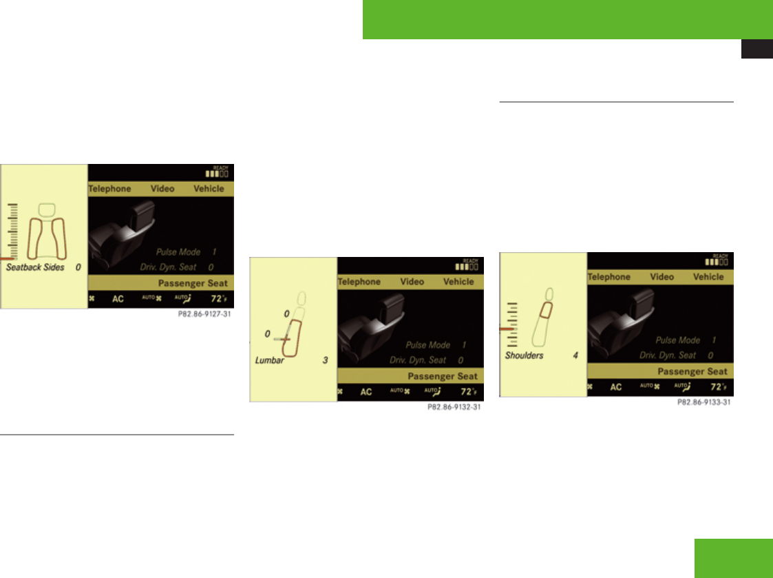
COMAND seats
235
XSelect seat (Y page 233).
XSelecting Seatback Sides: Slide qmr or
rotate ymz.
XConfirming selection: Press n.
A scale appears.
XSlide qmr or rotate ymz until desired
setting is reached.
XSaving setting: Press n.
Adjusting seat backrest curvature in
lumbar area
This function is used to adjust the air
chambers in the lumbar area of the seat
backrest.
XSelect seat (Y page 233).
XSelecting Lumbar: Slide omp or rotate
ymz.
XConfirming selection: Press n.
Crosshair appears.
You can use them to make two settings:
Rvertical: shift the point of greatest
curvature upward or downward
Rhorizontal: adjust the degree of
curvature
XSlide qmr or omp until desired setting is
reached.
XSaving setting: Press n.
Adjusting seat backrest curvature in
shoulder area
This function is used to adjust the air
chambers in the shoulder area of the seat
backrest.
XSelect seat (Y page 233).
XSelecting Shoulders: Slide omp or rotate
ymz.
XConfirming selection: Press n.
A scale appears.
XSlide qmr or rotate ymz until desired
setting is reached.
XSaving setting: Press n.
Control systems
Z
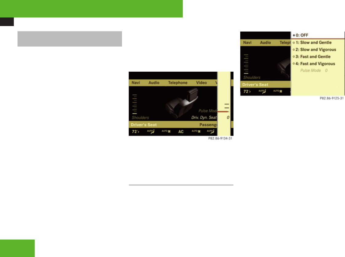
COMAND seats
236
Drive-dynamic multicontour seats,
front
For information on manual multicontour seat
settings, see “Multicontour seats,
front” (Y page 234).
iIf PRE-SAFE® has been activated, the air
pressure in the air chambers (sides of seat
cushion and seat backrest) of the drive-
dynamic multicontour seats is increased.
The drive-dynamic multicontour seat
automatically adjusts the lateral support
provided by the seat backrest to your driving
style.
The drive-dynamic multicontour seat
electronically controls the air pressure in the
air chambers of the seat backrest side
bolsters. This function improves driving
comfort and pleasure.
XSelect seat (Y page 233).
XSelecting Driv. Dyn. Seat: Slide omp
or rotate ymz.
XConfirming selection: Press n.
A scale appears.
You can choose between:
R0: off
R1: level 1
R2: level 2
XSlide qmr or rotate ymz until desired
setting is reached.
XSaving setting: Press n.
Pulse mode
XSelect seat (Y page 233).
XSelecting Pulse Mode: Slide omp or
rotate ymz.
XConfirming selection: Press n.
A list appears. You can choose between
different types of massage:
The current setting is indicated by a solid circle.
XSlide qmr or rotate ymz until desired
setting is reached.
XSaving setting: Press n.
iDepending on the setting, the massage
function runs for about 7 to 10 minutes.
Control systems
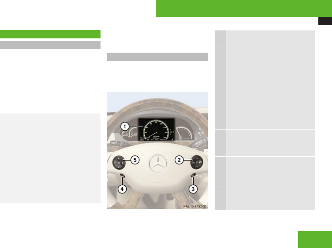
Instrument cluster control system
237
Instrument cluster control system
Introduction
The control system is activated as soon as the
starter switch is in position 2 (Y page 307).
The control system enables you to call up
information about your vehicle and to change
vehicle settings.
For example, you can use the control system
to find out when your vehicle is next due for
maintenance service, to call up statistical
data on your vehicle, and much more.
GWarning!
A driver’s attention to the road and traffic
conditions must always be his/her primary
focus when driving.
For your safety and the safety of others,
selecting features through the
multifunction steering wheel should only be
done by the driver when traffic and road
conditions permit it to be done safely.
Bear in mind that at a speed of just 30 mph
(approximately 50 km/h), your vehicle is
covering a distance of 44 feet
(approximately 14 m) every second.
The control system relays information to the
multifunction display.
Multifunction steering wheel
The displays in the multifunction display and
the settings in the control system are
controlled by the buttons on the multifunction
steering wheel.
1Multifunction display
2Press button
sto take a call
to dial5
to redial5
tto end a call
to reject an incoming call
Fto mute
Press button
æ
ç
to set the volume
to operate the RACETIMER6
3Press button
!to activate the Voice Control
System
4Press button briefly
Lto cancel the Voice Control
System, back, confirm
messages
Press and hold button
Lto select the standard display
5Function only available in telephone menu.
Control systems
Z

Instrument cluster control system
238
5Press button
&
(
to select menus
Press button briefly
$
%
to select function or scroll
through lists
within Audio menu to select
previous or next track, scene or
stored station
within Telephone menu to
switch to the phone book and
select a name or number
Press and hold button
$
%
within Audio to select previous
or next station in station list or
wave band
within Telephone menu to
start the quick search in the
phone book
Press button
#to confirm selection or
messages
Depending on the selected menu, pressing
the buttons on the multifunction steering
wheel will alter what appears in the
multifunction display.
The information available in the multifunction
display is arranged in menus and
accompanying functions. For example, in the
Settings menu, you will find functions for
making settings to your vehicle. There are
functions for calling up information and for
making settings to your vehicle.
It is helpful to think of the menus, and the
functions within each menu, as being
arranged in a circular pattern.
XPress ( or & repeatedly to switch
menus.
The number of menus available in the system
depends on which optional equipment is
installed in your vehicle.
XPress button L to return to the next
highest menu level.
From a menu’s highest level, you will always
see the screen from the Trip menu that was
last active. When you press L again, you
switch to the standard display
(Y page 241).
Multifunction display
1Main menus
2Text field
6AMG vehicles only.
Control systems


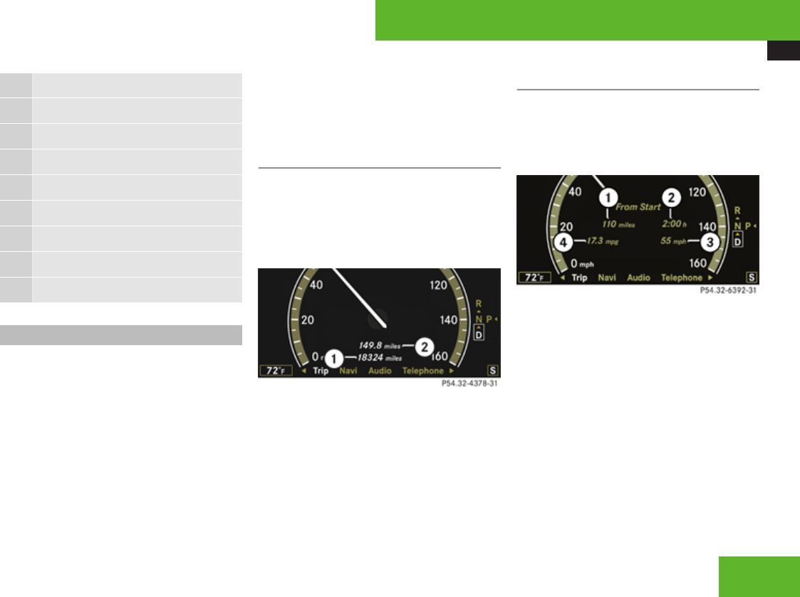
Instrument cluster control system
241
Function
1Trip menu (Y page 241)
2Navi menu (Y page 243)
3Audio menu (Y page 244)
4AMG7 menu (Y page 245)
5Telephone menu (Y page 248)
6Assistance menu (Y page 250)
7Service menu (Y page 251)
8Settings menu (Y page 252)
Trip menu
In the Trip menu, you can show an additional
display for the speedometer and call up or
reset your vehicle’s statistical data.
The following information is available:
RStandard display (Y page 241)
RFuel consumption statistics since start
(Y page 241)
RFuel consumption statistics since last reset
(Y page 242)
RResetting values (Y page 242)
RDistance to empty (Y page 242)
RDigital Speedometer (Y page 242)
Standard display
In the standard display, the trip odometer and
the main odometer appear in the
multifunction display.
XPress ( or & to select the Trip
menu.
1Main odometer
2Trip odometer
Fuel consumption statistics since start
XPress ( or & to select the Trip
menu.
XPress % or $ to select From
Start.
1Distance driven since start
2Time elapsed since start
3Average speed since start
4Average fuel consumption since start
All statistics stored since the last engine start
will be reset approximately 4 hours after the
SmartKey in the starter switch is turned to
position 0 or removed from the starter switch.
Resetting will not occur if you turn the
SmartKey back to position 1 or 2 within this
time period.
7AMG vehicles only.
Control systems
Z
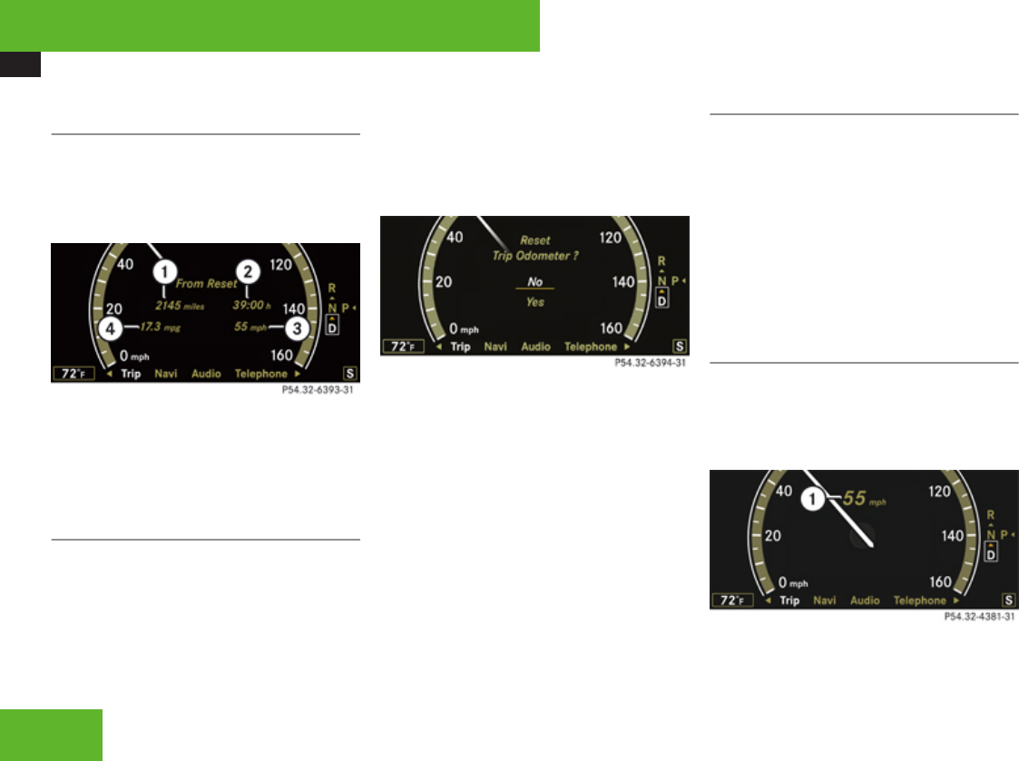
Instrument cluster control system
242
Fuel consumption statistics since last
reset
XPress ( or & to select the Trip
menu.
XPress % or $ to select From
Reset.
1Distance driven since last reset
2Time elapsed since last reset
3Average speed since last reset
4Average fuel consumption since last reset
Resetting values
You can reset the values for the following
functions:
RTrip odometer
RFuel consumption statistics since start
RFuel consumption statistics since last reset
XPress ( or & to select the Trip
menu.
XPress % or $ to select the function
you wish to reset.
XPress #.
Example illustration: Reset trip odometer
XPress % to select Yes.
XPress # to confirm.
iThe fuel consumption statistics reset
automatically to 0 after 99 999 miles or
9 999 hours, whichever occurs first.
Distance to empty
XPress ( or & to select the Trip
menu.
XPress % or $ to select Range.
The calculated remaining driving range
based on the current fuel tank level
appears in the multifunction display.
If only very little fuel is left in the tank, a
vehicle at the fuel pump ¿ appears
instead of the remaining driving range.
Digital speedometer
XPress ( or & to select the Trip
menu.
XPress % or $ to select the digital
speedometer.
1Digital speedometer
Control systems
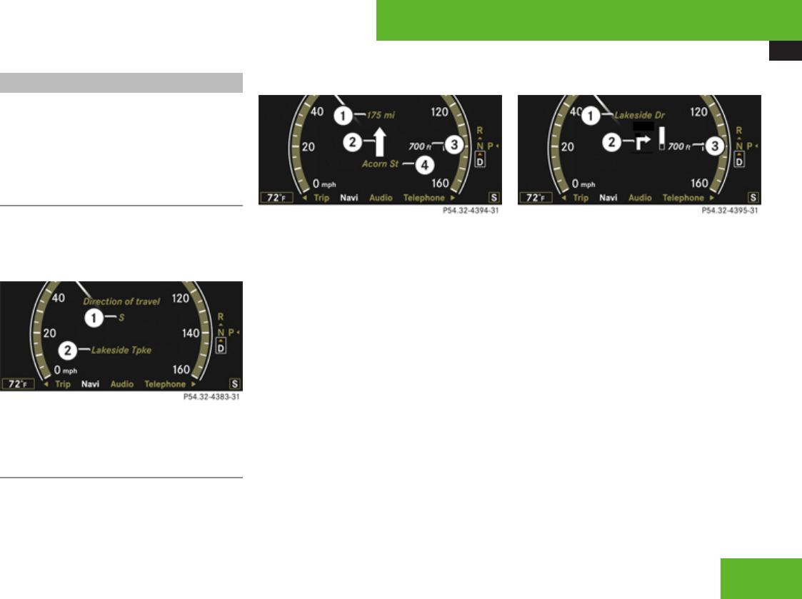
Instrument cluster control system
243
Navi menu
The display in the Navi menu depends on
whether route guidance is active or not.
XPress ( or & to select the Navi
menu.
Route guidance not active
The multifunction display shows the direction
of travel and the name of the street you are
currently driving on, if known by the
navigation system.
1Direction of travel
2Street you are currently driving on
Route guidance active
The image in the multifunction display
depends on whether you are being notified of
a driving maneuver.
No notification of driving maneuver
Example illustration
1Distance to destination
2Symbol for “follow the course of the road”
3Distance to next driving maneuver
4Street you are currently driving on
Notification of driving maneuver
Example illustration
1Street into which the driving maneuver
leads
2Symbol for “driving maneuver”
3Distance to driving maneuver and visual
distance display
When you are being notified of a driving
maneuver, you will see a visual distance
display 3 next to the driving maneuver
symbol. The visual distance display is
reduced from bottom to top the closer you
come to the announced driving maneuver.
Navigation status displays in the
instrument cluster
While route guidance is active, the following
messages may be shown in the multifunction
display:
R<
Control systems
Z

Instrument cluster control system
244
You have reached your destination.
RArea of dest. reached
You have arrived in the area of your
destination. The message appears, for
example, for relatively large POIs.
RNew Route...
COMAND calculates a new route, e.g.
because you have deviated from the
calculated route or due to a detour report.
Afterward, COMAND continues route
guidance.
RCalculating Route
COMAND is calculating a route. Afterward,
COMAND starts route guidance.
ROff Map
The vehicle’s location is outside of the
digital map’s range. The vehicle is in an off-
map position (Y page 142).
ROff Mapped Road
The vehicle is either on a road that has not
been digitized (Y page 142) or on the side
of a road, e.g. in a parking space.
RNo Route
COMAND cannot calculate a route to the
selected destination.
RDirection of Dest.
The vehicle has gone off the map during
route guidance (Y page 142).
Audio menu
The functions in the Audio menu operate the
audio equipment which you have currently
switched on.
The following functions are available:
RSelecting radio station (Y page 244)
ROperating DVD changer/audio CD/audio
DVD/MP3 (Y page 245)
ROperating video DVD (Y page 245)
If no audio equipment is currently switched
on, the message Audio OFF appears in the
multifunction display.
XTo adjust the volume: Press æ or
ç on the multifunction steering wheel.
Selecting radio station
The SIRIUS Satellite Radio is treated as a
radio application.
Additional optional satellite radio equipment
and a subscription to satellite radio service
provider are required for satellite radio
operation. Contact an authorized Mercedes-
Benz Center for details and availability for
your vehicle.
For more information on satellite radio
operation, see “Satellite
radio” (Y page 193).
XSwitch on the COMAND system and select
AM/FM radio (Y page 188) or satellite
radio (Y page 193).
XPress ( or & to select the Audio
menu.
The currently tuned station appears in the
multifunction display.
Example illustration for FM radio
1Station frequency
2Wave band setting
Control systems
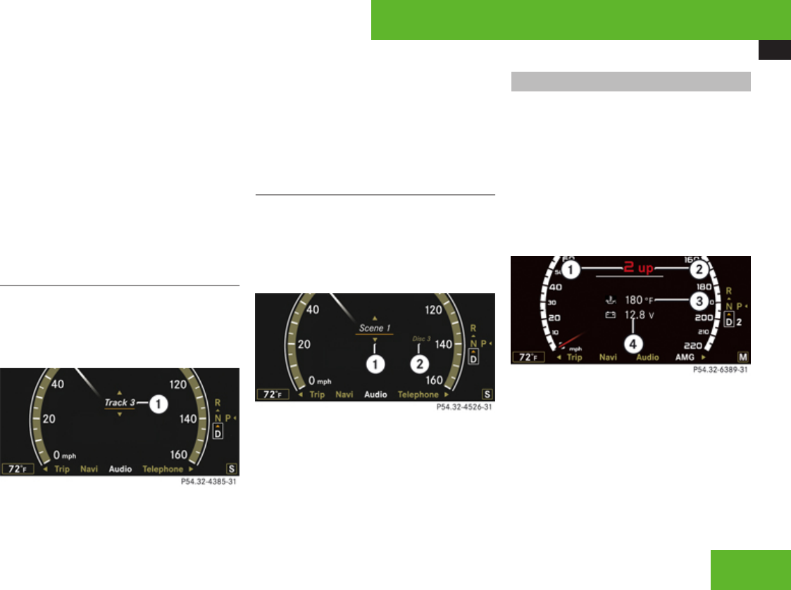
Instrument cluster control system
245
XSelect next or previous stored station:
Press button % or $ briefly to select
a stored station.
XSelect next or previous station in wave
band: Press and hold button % or
$ to select a station.
You can only change the frequency band and
save new stations using the COMAND
system, see (Y page 188) (AM/FM radio) or
(Y page 193) (satellite radio).
Operating DVD changer/audio CD/
audio DVD/MP3
XSwitch on the COMAND system and select
CD, DVD-Audio or MP3 (Y page 199).
XPress ( or & to select the Audio
menu.
Example: audio CD
1Current track
XPress % or $ to select a track.
iWhen you play a CD or DVD with text, the
multifunction display shows the name and
number of the track. For MP3s, only the
track is shown.
Operating video DVD
XSwitch on the COMAND system and select
Video £ Video £ Video DVD
(Y page 215).
XPress ( or & to select the Audio
menu.
1Current scene
2Disc number
XPress % or $ to select a scene.
AMG menu
This function is only available in AMG
vehicles.
The main screen of the AMG menu shows you
Rthe gear currently engaged
Rthe engine oil temperature
Rthe vehicle supply voltage
XPress button ( or & to select the
AMG menu.
1Gear indicator
2Upshift indicator
3Engine oil temperature indicator
4Vehicle supply voltage indicator
The engine oil temperature will be shown in
blue if the engine oil temperature has not yet
reached 176‡ (80†). During this time, avoid
driving at full engine speed.
Control systems
Z
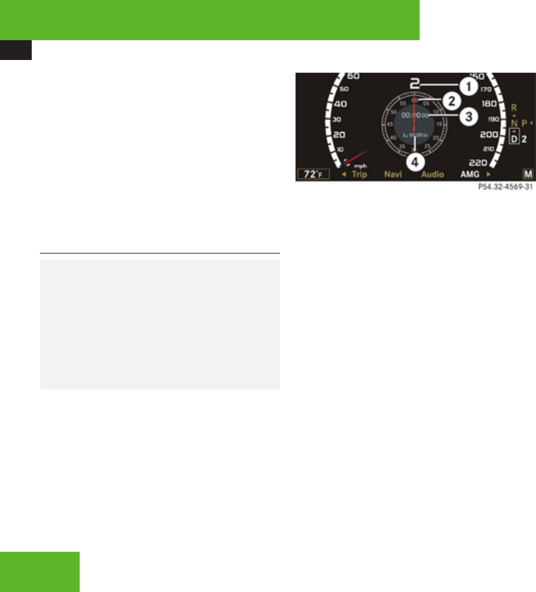
Instrument cluster control system
246
If the engine reaches the overspeed range in
the manual shift program, you will see up next
to gear indicator 1 as a reminder to upshift.
Use buttons % or $ to select the
following functions in the AMG menu:
RRACETIMER (Y page 246)
ROverall analysis (Y page 247)
RLap analysis (Y page 247)
RACETIMER
GWarning!
The RACETIMER feature is only for use on
roads and in conditions where high speed
driving is permitted. Racing on public roads
is prohibited under all circumstances and
the driver is and must always remain
responsible for following posted speed
limits.
The RACETIMER allows you to time and save
driving stretches.
XPress button ( or & to select the
AMG menu.
XPress $ to select the RACETIMER.
1Gear indicator
2Seconds display
3RACETIMER
4Lap
You can start the RACETIMER when the
engine is running or the starter switch is in
position 2 (Y page 307).
While the RACETIMER is being displayed, you
cannot adjust the audio volume using buttons
æ or ç.
XStarting: Press button æ.
XDisplaying intermediate time: Press
button ç while the timer is running.
The intermediate time is shown for
5 seconds.
XStopping: Press button æ.
When you stop the vehicle and turn the
SmartKey to position 1 (Y page 307) or, in
vehicles with KEYLESS-GO, turn off the
engine and do not open the driver’s door, the
RACETIMER stops timing. Timing is resumed
when you switch the ignition back on or
restart the engine and then press button
æ.
When you switch on the Night View Assist
(Y page 390) while the RACETIMER is
operating, the RACETIMER will continue to
run in the background but cannot be operated
with the multifunction steering wheel
buttons.
To stop the RACETIMER, switch off the Night
View Assist first.
Saving lap time and starting a new lap
You can save up to 16 laps.
XPress button ç while the timer is
running.
The intermediate time will be shown for
5 seconds.
XPress button ç within 5 seconds.
The intermediate time shown will be saved
as a lap time.
The RACETIMER begins timing the new lap.
The new lap begins to be timed as soon as
the intermediate time is called up.
Control systems
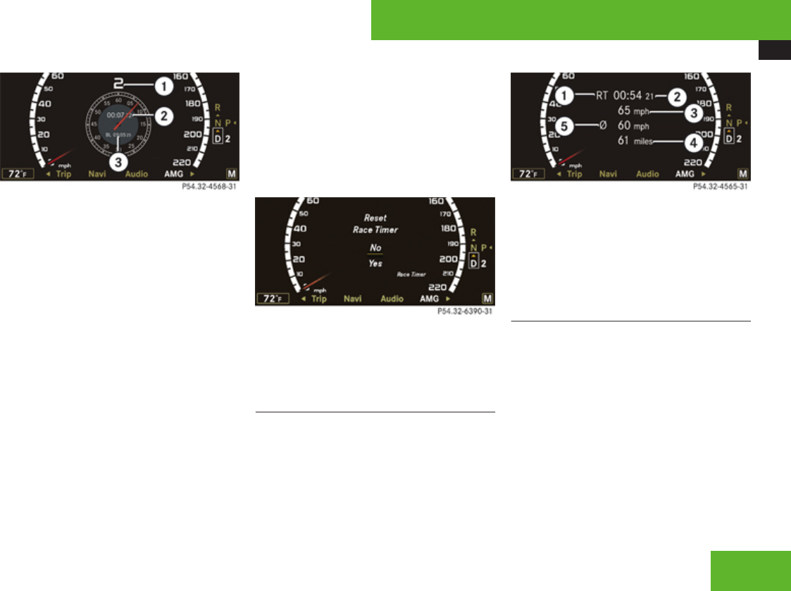
Instrument cluster control system
247
1Gear indicator
2RACETIMER
3Best lap time
Resetting current lap
XPress button æ while the timer is
running.
The timer stops.
XPress button ç.
The lap time is reset to “0”.
Deleting all laps
It is not possible to delete a single saved lap.
XPress button æ while the timer is
running.
The timer stops.
XPress button ç for at least 3 seconds.
XPress button æ.
The timer starts. The saved laps are
deleted.
or
XPress #.
The reset menu appears in the
multifunction display.
XPress % to select Yes and confirm with
#.
The saved laps are deleted.
Overall analysis
This function is only available if you have
saved at least one lap and have stopped the
RACETIMER.
XPress button $ repeatedly until the
overall analysis appears in the
multifunction display.
1Overall analysis of RACETIMER
2Overall driving time
3Maximum speed
4Overall distance driven
5Average speed
Lap analysis
This function is only available if you have
saved at least two laps and have stopped the
RACETIMER.
XPress button ( or & to select the
AMG menu.
XPress button $ repeatedly until the lap
analysis appears in the multifunction
display.
Each lap is shown in its own submenu. The
fastest lap is indicated by flashing symbol
1.
Control systems
Z
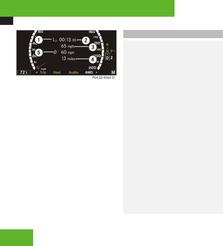
Instrument cluster control system
248
1Lap number
2Lap time
3Maximum speed during lap
4Lap length
5Average speed during lap
XPress button % or $ to see other lap
analyses.
Telephone menu
GWarning!
A driver’s attention to the road must always
be his/her primary focus when driving. For
your safety and the safety of others, we
recommend that you pull over to a safe
location and stop before placing or taking
a telephone call. If you choose to use the
telephone while driving, please use the
hands-free device and only use the
telephone when weather, road and traffic
conditions permit.
Some jurisdictions prohibit the driver from
using a mobile phone while driving a
vehicle.
Bear in mind that at a speed of just 30 mph
(approximately 50 km/h), your vehicle is
covering a distance of 44 feet
(approximately 14 m) every second.
Never operate radio transmitters equipped
with a built-in or attached antenna (i.e.
without being connected to an external
antenna) from inside the vehicle while the
engine is running. Doing so could lead to a
malfunction of the vehicle’s electronic
system, possibly resulting in an accident
and/or personal injury.
You can use the functions in the Telephone
menu to operate your telephone, provided it
is connected to a hands-free system and
switched on.
iVarious mobile phone cradles can be
installed in the front center armrest, see
separate installation instructions for the
mobile phone cradle. These mobile phone
cradles can be obtained from an authorized
Mercedes-Benz Center. For more
information on telephone, see
(Y page 424).
iA roof cargo container may impair mobile
phone reception. In an emergency, remove
the mobile phone from the mobile phone
cradle to make a call.
XSwitch on the telephone and the COMAND
system.
XPress button ( or & to select the
Telephone menu.
One of the following messages will appear
in the multifunction display:
RTelephone OFF: The telephone is
inserted in the mobile phone cradle but
it is switched off.
Control systems
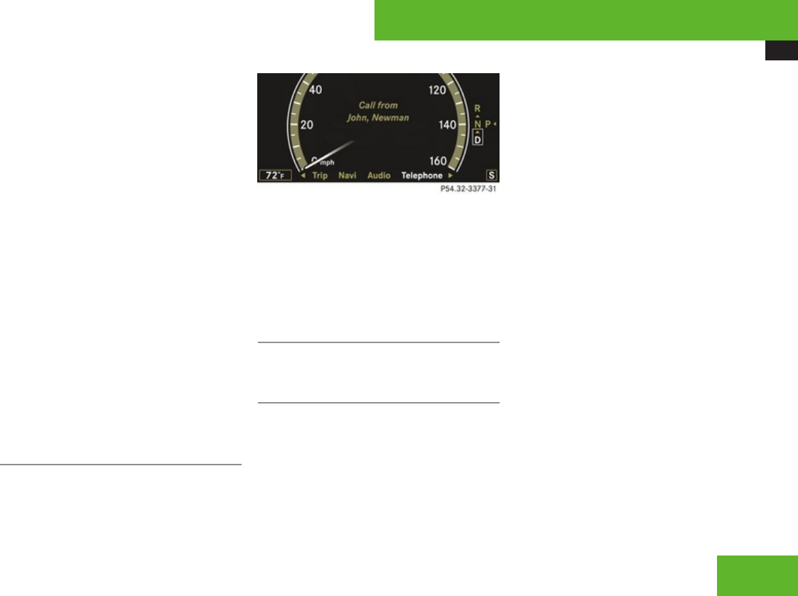
Instrument cluster control system
249
XSwitch on the telephone.
RNo telephone inserted: The
telephone is not inserted in the mobile
phone cradle.
XSwitch on the telephone.
XInsert the telephone in the mobile
phone cradle.
RPlease enter PIN or Enter unlock
code: The telephone is inserted in the
mobile phone cradle but the PIN or
unlock code has not been entered yet.
XEnter the PIN or the unlock coder
with the telephone, the COMAND
system or Voice Control.
The telephone will then search for a
network.
RReady or Ready (Roaming): The
telephone has found a network and is
ready for use. You can operate it using
the control system.
Answering a call
When your telephone is ready to receive calls,
you can answer a call at any time with the
ignition on. When you are in the Telephone
menu, you will see the following message in
the multifunction display:
XPress button s.
The caller’s number appears only if it is
transmitted.
The caller’s name appears only if the number
and the name are stored in the phone book.
Ending a call or rejecting an incoming
call
XPress button t.
Dialing a number from the phone book
When your telephone is ready to receive calls,
you may select and dial a number from the
phone book at any time.
iWhen you insert a Mercedes-Benz
approved mobile phone into the cradle, the
control system reads in the phone book
that is saved on the SIM card or in the
phone book of the mobile phone. This can
take several minutes, depending on how
many entries each phone book contains.
When you press %, $, (, &
or # during the download of the phone
book the message Reading telephone
data, please wait... appears in the
multifunction display.
When the message: Reading telephone
data, please wait... disappears, the
phone book has been loaded.
XPress button ( or & to select the
Telephone menu.
XPress button % or $ or # to
switch to the phone book.
The stored names are displayed in
ascending alphabetical order.
XPress button % or $ to select the
desired entry.
If you press and hold button % or
$ the system scrolls rapidly through the
list of names (quick search). After holding
button % or $ for a short while the
scrolling speed increases. Release the
button to stop the quick search. The search
stops automatically at the end of the list.
Control systems
Z

Instrument cluster control system
250
XPress button s or #.
If several entries are present for the same
name, they are all shown. Select the
desired entry and press button s or
# again.
The control system dials the selected
phone number.
If the connection is successful and this
feature is supported by your network
provider, the name of the party (if stored in
your phone book) you are calling will
appear in the multifunction display.
The control system stores the dialed
number in the redial memory.
or
XPress button t if you do not want to
make the call.
Redialing
The control system stores the most recently
dialed phone numbers. This eliminates the
need to search through your entire phone
book.
XPress button ( or & to select the
Telephone menu.
XPress button s.
XPress button % or $ to select the
desired number and/or name.
XPress button s or #.
The control system dials the selected
phone number.
Assistance menu
In the Assistance menu, you can change the
settings of your driving systems.
The following functions are available:
RDisplaying distance graphic, DISTRONIC
Plus (Y page 363)
RActivating/deactivating PRE-SAFE® Brake
(vehicles with DISTRONIC Plus only)
(Y page 250)
RSwitching on or off rear view camera
automatically (Y page 251)
RSwitching on or off Blind Spot Assist
(Y page 251)
Activating/deactivating PRE-SAFE®
Brake (vehicles with DISTRONIC Plus
only)
XPress ( or & to select the
Assistance menu.
XPress % or $ to select the PRE-SAFE
Brake function
XPress #.
1PRE-SAFE® Brake indicator :
XPress # again if you would like to
change the current status.
After the function has been activated,
indicator : appears on the left-hand
side of the multifunction display.
For more information, see (Y page 76).
Control systems
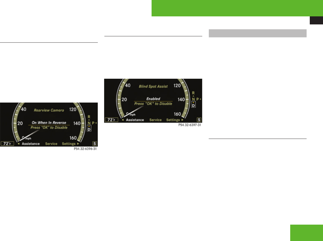
Instrument cluster control system
251
Switching on or off rear view camera
automatically
iThe image from the rear view camera is
shown on the COMAND system display.
XPress ( or & to select the
Assistance menu.
XPress % or $ to select the Rearview
Camera function
XPress #.
XPress # again if you would like to
change the current status.
The following settings are available:
On When In Reverse: The rear view
camera automatically switches on when
reverse gear is engaged.
Disabled: The rear view camera is not
switched on.
Switching on or off Blind Spot Assist
XPress ( or & to select the
Assistance menu.
XPress % or $ to select the Blind
Spot Assist function
XPress #.
XPress # again if you would like to
change the current status.
Service menu
In the Service menu the following functions
are available:
RCalling up messages (Y page 251)
RChecking tire inflation pressure
electronically with the Advanced TPMS
(Y page 459)
RCalling up the maintenance service
indicator display (Y page 482)
RChecking engine oil level (S 600 and
S 65 AMG) (Y page 445)
Calling up vehicle malfunction, warning
and system status messages stored in
memory
Use the vehicle status message memory
function to scan malfunction and warning
messages that may be stored in the system.
Such messages appear in the multifunction
display and are based on conditions or
system status the vehicle’s system has
recorded.
The vehicle status message memory function
only appears if there are any messages
stored.
Control systems
Z

Instrument cluster control system
252
GWarning!
Malfunction and warning messages are
only indicated for certain systems and are
intentionally not very detailed. The
malfunction and warning messages are
simply a reminder with respect to the
operation of certain systems. They do not
replace the owner’s and/or driver’s
responsibility to maintain the vehicle’s
operating safety. Have all required
maintenance and safety checks performed
on the vehicle. Bring the vehicle to an
authorized Mercedes-Benz Center to
address the malfunction and warning
messages.
XPress ( or & to select the Service
menu.
If conditions have occurred causing status
messages to be recorded, the number of
messages appears in the multifunction
display: 2 Messages.
XPress % or $ to select the
Messages function.
XPress # to confirm.
For malfunction and warning messages,
see “Vehicle status messages in the
multifunction display” (Y page 495).
XUse % or $ to scroll through the
messages.
If you turn the SmartKey in the starter switch
to position 0 and then back to position 2, all
messages will be deleted from the message
memory.
Settings menu
In the Settings menu the following functions
are available:
RSetting daytime running lamp mode (USA
only) (Y page 252)
RShowing or hiding additional speedometer
(Y page 253)
RSelecting speedometer display mode
(Y page 253)
RSwitching the radar sensors on or off
(Y page 253)
Setting daytime running lamp mode
(USA only)
XPress ( or & to select the
Settings menu.
XPress % or $ to select the Day
Running Lamps function.
XPress #.
XPress # again if you would like to
change the current status.
Depending on the previous status, the
daytime running lamps will be switched on
or off.
With Daytime Running Lamps mode
Enabled selected and the exterior lamp
switch at position M or *, the low-
beam headlamps are switched on when the
engine is running.
In low ambient light conditions the following
lamps will come on additionally:
RParking lamps
RTail lamps
RLicense plate lamps
RSide marker lamps
For more information on the daytime running
lamp mode, see “Lighting” (Y page 326).
Control systems

Instrument cluster control system
253
iMake sure the light switch is set to ¡
or * when you switch off the daytime
running lamps while driving at night.
Showing or hiding additional
speedometer
You can have an additional digital
speedometer shown in the multifunction
display. Depending on the setting for the
speedometer display mode (Y page 253), the
speed is shown in the unit of kilometers/hour
(setting miles) or miles/hour (setting km).
XPress ( or & to select the
Settings menu.
XPress % or $ to select the Add.
Speedometer function.
XPress #.
XPress # again if you would like to
change the current status.
Depending on the previous status, the
additional speedometer will be switched on
or off.
Selecting speedometer display mode
XPress ( or & to select the
Settings menu.
XPress % or $ to select the Units
function.
XPress #.
XPress # again if you would like to
change the current status.
Depending on the previous status, the
Display Unit Speed-/Odometer will be
switched to miles or km.
The additional speedometer (Y page 253)
will be shown in the other unit.
Switching the radar sensors on or off
If your vehicle is equipped with DISTRONIC
Plus, BAS Plus, or Park Assist it is equipped
with a radar sensor system which you can
switch on and off.
When traveling in Canada in a vehicle not
registered in Canada, you must switch off the
radar sensor system. Canadian law does not
permit the use of the radar sensor system for
vehicles from outside of Canada. When you
switch off the radar sensor system, the
following functions are deactivated:
RBAS Plus (Y page 70)
RPRE-SAFE® Brake (Y page 76)
RDISTRONIC Plus (Y page 360)
RPark Assist (Y page 379)
RAdvanced Parking Guidance (Y page 383)
RBlind Spot Assist (Y page 392)
iUSA only:
This device has been approved by the FCC
as a “Vehicular Radar System”. The radar
sensor is intended for use in an automotive
radar system only. Removal, tampering, or
altering of the device will void any
warranties, and is not permitted by the
FCC. Do not tamper with, alter, or use in
any non-approved way.
Any unauthorized modification to this
device could void the user’s authority to
operate the equipment.
Control systems
Z

Voice Control introduction
254
iCanada only:
This device complies with RSS-210 of
Industry Canada. Operation is subject to
the following two conditions:
1. This device may not cause interference,
and
2. this device must accept any
interference received, including
interference that may cause undesired
operation of the device.
Removal, tampering, or altering of the
device will void any warranties, and is not
permitted. Do not tamper with, alter, or use
in any non-approved way.
Any unauthorized modification to this
device could void the user’s authority to
operate the equipment.
XPress ( or & to select the
Settings menu.
XPress % or $ to select the Radar
Sensors function.
XPress #.
XPress # again if you would like to
change the current status.
Depending on the previous status, the
radar sensors will be switched on or off.
iThe selected status of the radar sensors
remains stored in memory even if the
engine is turned off and restarted.
The following message appears in the
multifunction display if the radar sensors are
switched off and you attempt to activate
DISTRONIC Plus, Park Assist or PRE-SAFE®
Brake:
Radar Sensors
(See Oper. Manual)
Disabled
Voice Control introduction
Safety notes
GWarning!
Only use the Voice Control System when
road and traffic conditions permit you to do
so. Otherwise you could be involved in an
accident in which you or others could be
injured.
GWarning!
Please devote your attention first and
foremost to the traffic situation you are in.
While the system permits hands-free phone
operation, attention to traffic may be
diverted not only by physical operation of a
phone, but also by the distraction of a
phone conversation while driving. As such,
for safety reasons, we encourage the driver
to stop the vehicle in a safe place before
answering or placing a phone call.
For safety reasons, you should only select
a destination when the vehicle is stationary.
While the navigation system provides
directional assistance, the driver must
remain focused on safe driving behavior,
especially attention to traffic and street
Control systems

Voice Control introduction
255
signs, and should utilize the system’s audio
cues while driving.
The navigation system does not supply any
information on stop signs, yield signs,
traffic regulations or traffic safety rules.
Their observance always remains in the
driver’s personal responsibility. DVD maps
do not cover all areas nor all routes within
an area.
Traffic regulations always have priority over
any route recommendations given.
Bear in mind that at a speed of just 30 mph
(approximately 50 km/h), your vehicle is
covering a distance of 44 feet
(approximately 14 m) every second.
GWarning!
Navigation announcements are intended to
direct you while driving without diverting
your attention from the road and driving.
Please always use this feature instead of
consulting the map display for directions.
Consulting the symbols or map display for
directions may cause you to divert your
attention from driving and increase your
risk of an accident.
GWarning!
Please do not use the Voice Control System
in an emergency, as the tone of your voice
may change in a stressful situation. This
could cause a delay in completing your
phone call in a timely manner. This could
distract you in an emergency situation and
cause you to be involved in an accident.
General information
The Voice Control System gives you the
capability to control the following systems on
your vehicle using spoken commands:
RTelephone (Y page 265)
RNavigation (Y page 258)
RAddress book (Y page 270)
RAudio (Y page 273) (AM/FM radio, CD/
DVD changer, MP3 player)
You control these systems using spoken
commands. Moreover, controls such as the
buttons on the multifunction steering wheel
(Y page 256) allow you to keep your hands
on the steering wheel.
The command vocabulary consists of
approximately 300 ready-to-use phrases. The
Voice Control System recognizes commands
and number sequences, irrespective of the
speaker. To optimize speech recognition for
your voice follow the individualization
process (Y page 293).
You can use the Voice Control System to call
up all of COMAND’s main menu items, with
the exception of the main menus for “Vehicle”
and “Navi”.
The commands and digit sequences can be
spoken without pausing between the
individual words. If an unavailable or incorrect
command is used, the Voice Control System
will prompt you for a new command by asking
“Please repeat” or “Please repeat your entry”.
In order to provide for a safe and comfortable
dialog, the Voice Control System
acknowledges important commands.
Control systems
Z
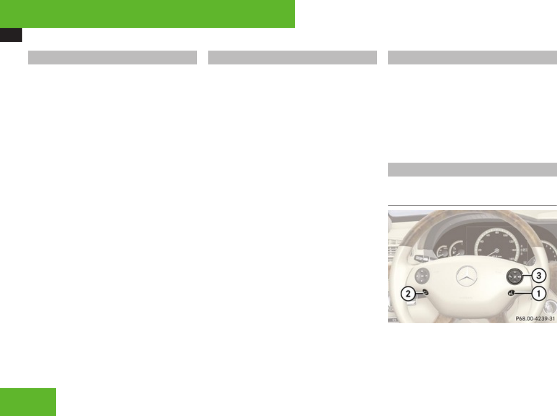
Voice Control introduction
256
Spelling
You may not need to spell the entire name
(street, intersection, city or point of interest)
especially if the name is lengthy. Spelling the
first three to five characters of the name
should be sufficient for the system to
recognize the name provided it is available on
the navigation DVD.
The selection appearing on the COMAND
display is sorted based on your recognized
voice input and a matching algorithm. You
can use the commands “Next page” or
“Previous page” to scroll up or down in the
list.
Use the command “Correction” to start over
by again spelling the name.
Speak each character as clearly as you can,
especially when they sound very similar (d or
e).
Command types
The Voice Control System commands can be
categorized as:
RGeneral Commands
These are commands always available to
you as soon as the Voice Control System is
activated (for example “Help” commands).
RLocal Commands
These are commands specific to the
currently active system shown in the
COMAND display (for example commands
to control the CD/DVD changer).
For a complete list of commands
(Y page 277).
iDuring Voice Control System operation
visual help windows also appear in the
COMAND display (Y page 257).
Active System
The active system is the system currently
shown in the COMAND display.
If, for example, you listen to the radio while
the telephone system is active on the
COMAND display, you have to switch to the
radio using the command “Radio” before you
can operate the radio.
Controls
Operation via the multifunction
steering wheel
Control systems

Voice Control introduction
257
Item
1!Activating the Voice Control
System
Accepting a call
2LCanceling Voice Control
3æIncreasing volume
çDecreasing volume
sTaking a call
Dialing
Redialing
tEnding a call
Rejecting an incoming call
iThe Voice Control System can be
canceled at any time, even during a dialog.
Please note that if the Voice Control
System is canceled during a dialog, then
the complete procedure is stopped and the
Voice Control System is canceled.
Activating the Voice Control System
XSwitch on COMAND (Y page 83).
XPress !.
An acoustic signal confirms the activation
of the system.
XSpeak a command.
Canceling the Voice Control System
XPress L.
or
XSpeak the command “Cancel”
(except for speaking voice entries, entering
a city or carrying out individualization).
or
XPress any COMAND button.
Setting volume level
XActivate the Voice Control System.
XSpeak a command, for example “Help”.
XPress æ or ç. The volume is
increased or decreased during voice
output.
or
XSet volume for voice output using the
COMAND volume thumbwheel on the lower
part of the front center console
(Y page 92).
Displays
COMAND Display
In addition to the acoustic help function, a
visual help function (Y page 97) is available
on the COMAND display.
Upon activating the Voice Control System,
the most important available commands for
the currently active system appear on the
COMAND display.
When the Voice Control System requires
additional information from the user, a
selection list is shown on the COMAND
display in the address book and navigation
system.
Control systems
Z
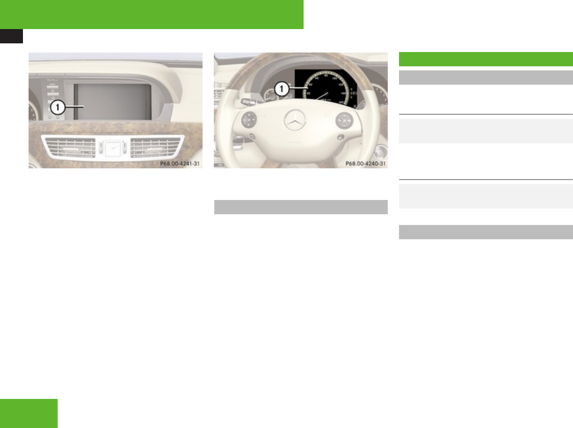
Voice Control navigation
258
1COMAND display
Multifunction display
For example, telephone numbers are shown
in the multifunction display while dialing
when the main Telephone menu is selected
in the instrument cluster control system.
1Multifunction display
Symbols
The following symbols are found in the Voice
Control System pages:
sThis symbol stands for commands and
voice entries you are speaking.
tThis symbol stands for voice output by
the Voice Control System.
uThis symbol indicates that information
is available on the COMAND display.
Voice Control navigation
Important notes
Safety notes for using the Voice Control
System
GObserve Safety notes, see
page 254.
Safety notes for using the navigation
system
GObserve Safety notes, see
page 99.
Navigation operation
The Voice Control System allows you to
Renter a state or province
Renter a city
Rspell the name of a city
Rspell the name of district or center
Rspell the name of a street
Rspell the name of an intersection
Renter a house number
Renter a complete address
Control systems

Voice Control navigation
259
Rselect one of your last destinations
Renter a POI (point of interest)
Rselect one of your last destinations
Rsave a destination
Rnavigate to a destination stored in the
destination memory of the address book
Rstart route guidance
Rdisplay the map
Rzoom in or zoom out of the map
Rlisten to the destination memory
Rcancel route guidance
Rturn guide instructions on or off
Before you can operate navigation using the
Voice Control System, you have to activate
the Voice Control System (Y page 257).
Selecting navigation mode
XPress !.
XSpeak the command “Navigation”.
XPress !.
XSpeak one of the navigation commands.
Navigation commands
iYou cannot start the route guidance until
all necessary address data has been
entered.
For a complete list of commands
(Y page 277).
“Help navigation”/“Help”
Use the command “Help navigation” or
“Help” to read out an option list of available
functions and commands that can be used in
conjunction with the navigation system.
“Enter state”,“Enter province”
Use the command “Enter state” or “Enter
province” to select a different state or
province on the navigation DVD.
Sample dialog:
sEnter state
tPlease say the name of the state
sNew York
uThe system shows a numbered list of
states recognized by the system
tPlease select a line number
sNumber two
or to accept, say
sYes
tState accepted
The selected entry is adopted from the list.
“Last states”
Use the command “Last states” to select a
state or province from among a number of
last selected states or provinces.
Dialog for entering a complete
address
“Enter destination”
Use the command “Enter destination” to
enter a complete destination address.
The system guides you through the dialog. As
soon as a valid address has been entered, you
can start route guidance or save the
destination. For information on spelling
(Y page 263).
Sample dialog:
sEnter destination
tPlease spell a New York street name
sB-R-O-A-D-W
Control systems
Z

Voice Control navigation
260
uThe system displays a numbered list of
matching street names on the
COMAND display
tPlease select a line number
sNumber two
tNumber two accepted
tDo you want to enter a house number?
sNo
tDo you want to enter an intersection?
sNo
tDo you want to spell the town’s name?
sYes
tPlease spell the town name
sN-E-W-Y-O-R-K
uThe system displays a numbered list of
matching city names on the COMAND
display
tPlease select a line number
sNumber one
tNumber one accepted
tDo you want to start route guidance?
sYes
tStarting route guidance
The system calculates the route and, upon
completing route calculation, starts route
guidance.
iYou may not need to spell the entire name
(street, intersection, city or point of
interest) especially if the name is lengthy.
Spelling the first three to five characters of
the name should be sufficient for the
system to recognize the name provided it
is available on the navigation DVD.
iThe selection appearing on the COMAND
display is sorted based on your recognized
voice input and a matching algorithm.
You can use the commands “Continue” or
“Back” to scroll up or down in the list.
Use the command “Correction” to start
over by again spelling the name.
Speak each character as clearly as you can,
especially when they sound very similar (d
or e).
“Points of interest”
Use the command “Points of interest” to
select a point of interest (POI) such as
airports, railroad stations, gas stations etc.
Sample dialog:
sPoints of interest
uThe system shows the following list on
the COMAND display:
Rcurrent position
Rother town/city
RGlobal POI
tPlease select a line number
sNumber one
uThe system displays a numbered list of
available POI categories: Select POI
category menu
tPlease select a line number
sNumber one
uThe system displays a numbered list
search categories: Find menu
tPlease select a line number
sNumber one
uThe system displays a numbered list of
airports sorted by distance
tPlease select a line number
sNumber one
tPoint of interest accepted
tDo you want to start route guidance?
Control systems

Voice Control navigation
261
sYes
tStarting route guidance
iDepending on the number of categories
and POI’s available for a given area, the
system may display several lists on each of
which you may have to make a selection by
speaking the desired line number or you
have to spell the name of a POI.
“Next POI”
With the commands
R“Next gas station”
R“Next parking lot”
R“Next Mercedes-Benz service”
R“Next restaurant”
R“Next hospital”
you can select POIs in your vicinity.
Sample dialog:
sNext gas station
uThe system shows a numbered list of
gas stations on the COMAND display
tPlease select a line number
sNumber one
tNumber one accepted
tDo you want to start route guidance?
sYes
The system calculates the route and, upon
completing route calculation, starts route
guidance.
“Last destinations”
Use the command “Last destinations” to
select a destination from among a number of
destinations last navigated to.
“Save destination”
Use the command “Save destination” to save
the current destination in the address book.
iThe Voice Control System may recognize
names even if not saved in your voice. For
best possible call-up performance,
however, you should speak and save the
names you intend to use yourself.
If an entry is already available in the
address book, the system will ask you if you
would like to add the address to the
available entry.
Sample dialog:
sSave destination
tPlease say the name
sJohn Smith
tPlease repeat the name
sJohn Smith
tWhere do you want to save: home or
work?
sWork
tThe destination has been saved
“Navigate to <voice entry>” (address
book)
Use the command “Navigate to <voice
entry>” to start route guidance by selecting
voice entry with a saved destination address
from the COMAND address book.
A voice entry may have two different
destination addresses associated with it
(home or work).
The system confirms your command,
calculates the route, and begins route
guidance. If only one address is stored, you
can use the command “Navigate <voice
name>” to select the stored destination
address for that name.
If two addresses are stored, you can use the
commands
R“Navigate <voice name> home”
Control systems
Z

Voice Control navigation
262
or
R“Navigate <voice name> work”
to directly select between home or work
address for that name. The system
confirms your selection, calculates the
route, and begins route guidance.
Sample dialog:
sNavigate to John Smith
If more than one address exists for this
voice entry, the Voice Control System
will prompt you:
tNavigate to home or work?
sWork
tJohn Smith work
Starting route guidance
“Start route guidance”
Use the command “Start route guidance” to
start route guidance after entering a valid
destination.
Sample dialog:
sStart route guidance
tStarting route guidance
Route guidance begins.
“Guidance instructions on”
Use the command “Guidance instructions on”
to have the Voice Control System repeat the
last guidance instruction. If guidance voice
output was previously muted, using this
command will deactivate the muting of the
voice output.
“Guidance instructions off”
Use the command “Guidance instructions
off” to mute the system’s guidance voice
output.
“Cancel route guidance”
Use the command “Cancel route guidance”
to cancel route guidance.
Sample dialog:
sCancel route guidance
tAre you sure you want to cancel route
guidance?
sYes
Route guidance is canceled.
or
sNo
tCancel
The dialog with the Voice Control System is
canceled. Route guidance remains active.
“Map”
Use the command “Map” to activate or switch
to map display.
“Zoom in”, “Zoom out”
Use these commands to zoom in on map or
to zoom out of map to the desired level of map
detail.
“Zoom in completely”, “Zoom out
completely”
These commands are used to adapt the map
display directly to the smallest or largest map
scale.
“List destination memory”
Use the command “List destination memory”
to have the system read out all destination
memory entries and select and entry for route
guidance.
Sample dialog:
sList destination memory
Control systems

Voice Control navigation
263
The system reads out the address
book destination memory.
To select a voice entry and adopt address for
route guidance:
XWhen the system reads the desired entry,
press !.
If more than one address is available, the
system will prompt you:
tNavigate to home or work?
sHome
The system reads the selected voice
entry and starts route guidance.
To cancel the dialog:
XPress L.
You have canceled the dialog. The system
confirms cancellation by saying “Cancel”.
Commands for entering parts of an
address
“Enter town”
The “Enter town” command is used to enter
any larger town or city in the USA or Canada.
iIf the desired town/city does not appear
on the list of towns/cities, the town or city
can be entered by using the “Spell town”
command.
iYou can scroll through the list by using the
“Continue” or “Back” command. Say
“Correction” to enter the town or city again.
Sample dialog:
sEnter town
tPlease spell the name of the town
sE-A-S-T-O-N
uThe system displays a numbered list of
available city names
tPlease select a line number
sNumber one
tNumber one, town accepted
The city selected is adopted for route
guidance.
“Spell town”
Use the command “Spell town” to enter a city
name by spelling mode and see if it matches
an entry available on the navigation DVD.
Speak the characters as a continuous string
(five to seven characters). The system then
displays a list of cities on the COMAND
display from which you can select the desired
city.
Sample dialog:
sSpell town
tPlease spell the town name
sN-E-W-Y-O-R
uThe system displays a numbered list of
available city names
tPlease select a line number
sNumber one
tNumber one, town accepted
The city selected is adopted for route
guidance.
iYou can use the commands “Continue” or
“Back” to scroll up or down in the list. Use
the command “Correction” to start over
again by spelling the name of the town.
iYou must also spell foreign towns or cities
in English. Please note that the list on the
Control systems
Z

Voice Control navigation
264
COMAND display is sorted according to the
probability of the voice recognition.
Speak each character as clearly as you can,
especially when they sound very similar (d
or e).
“District” or “Center”
Use the command “District” or “Center” to to
spell a city location in the city previously
selected.
Speak the characters as a continuous string
(five to seven characters). The system then
displays a list of available city districts or
centers on the COMAND display. Select the
desired city center from that list.
Sample dialog:
sDistrict
tPlease spell the center
sS-T-A-T-E-N-I-S
uThe system displays a list of available
districts if more than one name
matches the name of a district for the
given city
tPlease select a line number
sNumber one
tNumber one, center accepted
The district selected is adopted for route
guidance.
“Street”
Use the command “Street” to spell and select
a street for the adopted city. Only street
names available on the navigation DVD can
be selected.
Speak the characters as a continuous string
(five to seven characters). The system then
displays a list of available street names on the
COMAND display. Select the desired street
name from that list.
Sample dialog:
sStreet
tPlease spell the name of the street
sF-O-R-E-S-T
uThe system displays a numbered list of
available street names
tPlease select a line number
sNumber one
tNumber one, street accepted
The street name selected is adopted for route
guidance.
“Intersection”, “Cross street”
Use the command “Intersection” or “Cross
street” to spell and select an intersection.
Speak the characters as a continuous string
(five to seven characters). The system then
displays a list of available intersections on the
COMAND display. Select the desired
intersection from that list.
Sample dialog:
sIntersection
tPlease spell the first street name
sF-O-R-E-S-T
tPlease spell the name of the crossing
street
sD-U-D-L-E-Y
uThe system displays a numbered list of
available intersections on the
COMAND display
tPlease select a line number
sNumber one
tIntersection accepted
The intersection is adopted for route
guidance. If an address at the intersection is
recognized, the system asks if it is correct.
Say “Yes” or “No”.
Control systems

Voice Control telephone
265
“House number”
Use the command “House number” to select
a house number for the street previously
selected. Speak the house number in single
digits.
Sample dialog:
sHouse number
tPlease say the house number in single
digits
sThree two
tIs three two correct?
sOK
tHouse number accepted
The house number is adopted for route
guidance.
Voice Control telephone
Safety notes
i For more information on telephone, see
(Y page 424) and (Y page 155).
Safety notes for using the Voice Control
System
GObserve Safety notes, see
page 254.
Safety notes for using the telephone
GObserve Safety notes, see
page 155.
Telephone operation
The Voice Control System gives you the
following capabilities:
REntering a telephone unlock code.
RDialing a phone number by speaking the
telephone number.
RStoring names and numbers in the
COMAND address book.
RDialing a phone number by speaking the
name of an COMAND address book entry.
RDeleting an address book entry from the
address book.
RHaving the system read out the phone book
of the address book entry by entry.
RManaging and accessing an automated
answering system/voice mail box.
RRedialing names and numbers.
The Voice Control System detects whether
Ryour telephone is switched on
Rthe corresponding mobile network is
logged in
Rit is possible to dial
If dialing is not possible, the Voice Control
System will advise you accordingly.
iYou can continue operating your mobile
phone using the telephone keypad or
keypad on your phone.
Before you can operate the telephone using
the Voice Control System, you have to
activate the Voice Control System
(Y page 257).
Control systems
Z

Voice Control telephone
266
Telephone commands
For a complete list of commands, see
(Y page 277).
“Telephone”
Use the command “Telephone” to activate
the telephone main menu. Use this command
if you want the digits you are entering to
appear on the COMAND display.
“Help telephone”
The Voice Control System features a
comprehensive help function.
Use the command “Help telephone” and the
Voice Control System will read out an option
list of available functions and commands that
can be used in conjunction with the telephone
(Y page 97).
“Enter PIN”
iThe PIN (only GSM mobile phones)
prompt starts automatically whenever the
phone is locked and you wish to use it.
Use the command “Enter PIN” to input the
code to unlock your telephone. After
speaking the command, you are prompted to
enter the code.
Speak the code
Ras a continuously spoken string of digits, or
Rin digit blocks (three to five digits in each
block).
Digits from “Zero” to “Nine” may be used.
After each digit block (separate the digit
blocks by using an approximately 0.5 second
pause), the Voice Control System repeats the
recognized digits and waits until you continue
speaking.
Sample dialog:
sEnter PIN
tPlease say the PIN
sZero zero one one
tZero zero one one
sOK
“Dial number”
You can dial a phone number using the
command “Dial number”.
Digits from “Zero” to “Nine” may be used.
The phone number must be spoken
Ras a continuously spoken string of digits, or
Rin digit blocks (three to five digits in each
block).
After each digit block (separate the digit
blocks by using an approximately 0.5 second
pause), the Voice Control System repeats the
recognized digits and waits until you continue
speaking.
When dialing 1-800 numbers, you may
pronounce the first four digits as “One eight
hundred” and the system will recognize the
spoken entries as “One eight zero zero”. All
other numeric entries must be spoken as
individual numbers.
Sample dialog:
sDial number
tPlease say the number
sOne two three
tOne two three
sFour five six seven
tFour five six seven
sOK
tDialing
iYou can also dial the telephone number
spoken by pressing buttons on the
multifunction steering wheel (instead of
using the command “OK”):
You can dial the telephone number before
all numbers are recited in full.
Control systems

Voice Control telephone
267
“Confirm”
Using the command “Confirm” will repeat all
digits spoken up to that point. Upon repeating
the digits, the system will prompt you to
continue your input.
Sample dialog:
sDial number
tPlease say the number
sOne two three
tOne two three
sConfirm
tOne two three, please continue
sFour five six seven
tFour five six seven
sOK
tDialing
“Correction”
Using the command “Correction” will correct
the last entered digit block. After speaking
the command, the last digit block is deleted
and all previously entered digits are repeated.
The system then prompts you to continue
your input.
Sample dialog:
sDial number
tPlease say the number
sOne two three
tOne two three
sFour five six seven
tFive five six seven
sCorrection
tOne two three, please continue
sFour five six seven
tFour five six seven
sOK
tDialing
“Delete”
Using the command “Delete” will erase all
digits entered. The system then prompts you
to start your input again.
Sample dialog:
sDial number
tPlease say the number
sOne two three
tOne two three
sFour five six seven
tFour five six seven
sDelete
tNumber deleted. Please enter the
number again
sFour two seven three
tFour two seven three
sThree nine one
tThree nine one
sOK
tDialing
“Redial”
Use the command “Redial” to dial the last
dialed number.
“Save name” (COMAND address book)
Use the command “Save name” to create a
new entry in your COMAND address book.
After using the command, the system will
prompt you to enter a phone number.
Digits from “Zero” to “Nine” can be entered
(Y page 266).
Speak the telephone number
Ras a continuous string
Control systems
Z

Voice Control telephone
268
or, with longer phone numbers,
Rin digit blocks (three to five digits in each
block).
After each digit block (separate the digit
blocks by using an approximately 0.5 second
pause), the Voice Control System repeats the
recognized digits and waits until you continue
speaking.
After the command “OK”, you will be
prompted up to two times to input the name.
When repeating the name, make sure that you
pronounce it in the same manner as during
the first input. Otherwise the name cannot be
saved and the Voice Control System cancels
the save procedure.
iThe Voice Control System may recognize
names even if not saved in your voice. For
optimum call-up performance, however,
you should speak and save the names you
intend to use yourself.
iYou can also add a name to an entry by
calling up the corresponding menu on
COMAND and saying the name twice
(Y page 182).
Sample dialog:
sSave name
tPlease say the number first
sOne two three
tOne two three
sFour five six seven
tFour five six seven
sOK
tPlease say the name
sJohn Smith
tPlease repeat the name
sJohn Smith
tDo you want to save the number in a
category?
sNo
tName and number saved
“Dial name” (COMAND address book)
Use the command “Dial name” to place a
phone call by selecting a name previously
saved in your personal address book.
Sample dialog:
sDial name
tPlease say the name
sJohn Smith
If several telephone numbers exist for
the same entry, the Voice Control
System will ask for clarification.
tDo you want to place a work call or a
home call?
sWork
tJohn Smith work
Dialing
“Call <voice entry>” (address book)
Use the command “Call <voice entry>” to
place a phone call by directly selecting a
name previously stored in your address book.
One address book entry can have up to three
different telephone numbers (mobile phone/
car/land line) for both the home and work
fields.
If only one telephone number is stored for a
given name, you can recall the entry using the
command “Call John Smith”.
If several telephone numbers are associated
with one entry, you can recall the desired
telephone number by using the following
commands:
R“Call John Smith home”
R“Call John Smith work”
R“Call John Smith home cell phone”
Control systems

Voice Control telephone
269
R“Call John Smith home car”
R“Call John Smith home land line”
R“Call John Smith work cell phone”
R“Call John Smith work car”
R“Call John Smith work land line”
The system confirms your input and the
number is dialed.
Sample dialog:
sCall John Smith
If several telephone numbers exist for
the same entry, the Voice Control
System will ask for clarification.
tDo you want to place a work call or a
home call?
sWork
tJohn Smith work
Dialing
“Delete name” (COMAND address book)
Use the command “Delete name” to delete a
name from the COMAND address book.
Sample dialog:
sDelete name
tThe name, please
sSmith office
tSmith office: Would you like to delete
the voice name?
sYes
tThe voice name is deleted
“List phone book” and dialing a phone
number
Use the command “List phone book” to listen
to all voice entries in the phone book with a
phone number stored, and select an entry and
dial that number.
Sample dialog:
sList phone book
The system reads out the complete
phone book entry by entry.
Selecting an entry and dialing that
number
XFor the desired entry, press ! during or
immediately after voice output.
If more than one phone number exists for
a given entry, the Voice Control System
prompts:
tDo you want to place a work call or a
home call?
sHome
The system reads out the name of the
selected entry and dials the
corresponding number.
Canceling the dialog
XPress L.
The system confirms “Cancel”. The dialog
is concluded.
Managing automated answering
system/voice mail box
Activate the Voice Control System to access
and manage your answering machine/voice
mail box.
XActivate the Voice Control System during a
phone call (Y page 257).
An acoustic signal confirms the activation
of the system.
XSpeak the required digits (“Zero” to
“Nine”).
or
XSpeak the required words “Star” and
“Pound”.
XSpeak the final command “OK”.
The system dials the number entered.
Control systems
Z

Voice Control address book
270
Voice Control address book
Safety notes
GWarning!
Please devote your attention first and
foremost to the traffic situation you are in.
Before your journey, please familiarize
yourself with the address book functions.
Only use the Voice Control System when
road and traffic conditions permit you to do
so. Otherwise you could be involved in an
accident in which you or others could be
injured.
COMAND address book overview
The Voice Control System address book
function gives you the capability to store
names and associated phone numbers and
address information.
You can store up to 80 speaker-dependent
voice entries in the Voice Control System
address book.
Using these voice entries, you can dial a
phone number stored in address book or start
route guidance to an address stored in the
address book. Available commands are
dependent on the status of the address book.
The address book can be in one of the
following status:
RAddress book not open
RAddress book open
Operation with address book not
open (global)
The Voice Control System gives you the
following capabilities:
RStoring a name (Y page 267).
RDialing a name (Y page 268).
RDeleting a name (Y page 269).
RNavigating to an entry (Y page 261).
RListing address book (Y page 271).
RListing phone book of the address
(Y page 269).
RListing address book destination memory
(Y page 262).
RDeleting the address book (Y page 271).
ROpening the address book.
Opening address book
XPress !.
XSpeak the command “Address book”.
XPress !.
XSpeak one of the address book commands
described below.
Operation with address book open
(local)
In addition to the capabilities listed when the
address book is not open, the address book
opened allows you to:
Ropen an entry using the corresponding
voice entry
Ropen any entry by spelling the name
XOpening entry: Speak the command
“Open entry”.
Control systems

Voice Control address book
271
Operating and using address book
XPress !.
XSpeak one of the following commands
depending on the address book status
(open or not open).
Available commands with the address
book not open
For a complete list of commands, see
(Y page 277).
“Help address book”
Use the command “Help address book” to
have the Voice Control System read out an
option list of all available commands for the
address book.
“Save name”
For information to “Save name”, see
(Y page 267).
“Dial name”
For information to “Dial name”, see
(Y page 268).
“Call <voice name>”
For information to “Call <voice name>”, see
(Y page 268).
“Delete name” (address book)
Use the command “Delete name” to delete a
voice name from your address book.
Sample dialog:
sDelete name
tPlease say the name
sJohn Smith
tDo you want to delete John Smith?
sYes
tThe voice name is deleted
“Navigate to <voice entry>” (address
book)
For information to “Navigate to <voice
entry>”, see (Y page 261).
“List address book”
Use the command “List address book” to
have the system read out all available address
book entries and, if desired, select an entry
when it is being read.
Sample dialog:
sList address book
The system reads out all available address
book entries.
XSelecting address book entry: When the
system reads the desired entry,
press !.
The entry is selected and shown on the
COMAND display.
XCanceling the dialog: Press L.
You have canceled the dialog. The system
reads out “Cancel”.
“List phone book” and dialing a phone
number
For information to “List phone book” and
dialing a phone number, see (Y page 269)
“List destination memory”
For information to “List destination memory”,
see (Y page 262).
“Delete address book”
Use the command “Delete address book” to
delete all or individual voice names of the
address book entries. Only the voice name is
Control systems
Z

Voice Control address book
272
deleted; the remaining data in the entry are
retained.
“Address book”
Use this command to open the address book.
Available commands with the address
book open
“Help address book”
Use the command “Help address book” to
have the Voice Control System read out an
option list of all available commands for the
address book.
“Open <voice name>”
Use the command “Open <voice name>” to
open an entry in your address book that has
a voice name already assigned to it.
Sample dialog:
sOpen John Smith
uThe entry John Smith appears on the
COMAND display
“Select entry”
Use the command “Select entry” to open an
entry in your address book.
Sample dialog:
sSelect entry
tPlease say the name
sJohn Smith
uThe entry John Smith appears on the
COMAND display.
“Spell entry”
Use the command “Spell entry” to open an
address book entry by spelling the name.
Speak the name as a continuous string (five
to seven characters).
The system will display a list of possible
matches on the COMAND display from which
you can select the desired entry.
Sample dialog:
sSpell entry
tPlease spell the name
sS-M-I-T-H
uThe system displays a numbered list of
matching entries on the COMAND
display
tPlease select a line number
sNumber two
uThe system opens the entry associated
with line number two on the list
iYou can use the commands “Continue” or
“Back” to scroll up or down the next page.
Use the command “Correction” to exit the
current selection list and spell the name
again.
Control systems

Voice Control radio
273
Voice Control radio
Safety notes
GWarning!
Please devote your attention first and
foremost to the traffic situation you are in.
Before your journey, please familiarize
yourself with the radio functions.
Only use the Voice Control System when
road and traffic conditions permit you to do
so. Otherwise you could be involved in an
accident in which you or others could be
injured.
Radio operation
The Voice Control System gives you the
capability to:
RSelecting a station.
RSeeking a station.
RSelecting a specific frequency.
RSaving up to 20 stations in your station list.
RSelecting frequency band (FM or AM).
RSelecting weatherband.
RSwitching to satellite radio.
RDeleting station (from station list).
RListing the station list.
RDeleting the station list.
To operate the radio using the Voice Control
System, the Voice Control System must be
activated (Y page 257).
Selecting radio mode
XPress !.
XSpeak the command “Radio”.
XPress !.
XSpeak one of the radio commands.
The system switches to the last tuned
station in the selected band.
Radio commands
For a complete list of commands
(Y page 277).
“Help Radio”
Use the commands
R“FM”
R“AM”
R“Weatherband”
to select the desired frequency band or
switch the radio to the weatherband.
“Sat Radio”
Use this command for switching on the
satellite radio.
“Next station” or “Previous station”
The following commands are used to start the
station search and to tune in the next station:
R“Next station”
R“Previous station”
Selecting frequency (FM, AM only)
You may, for example, select a frequency in
the FM band (87.9 to 107.9 Megahertz)
directly using a verbal command such as
“Ninety-five five”. The Voice Control System
also recognizes the words “frequency”,
“point” and “megahertz”. You may for
example use the command “Frequency
ninety-five point five”.
Sample dialog:
sNinety-five point five
Control systems
Z

Voice Control radio
274
The Voice Control System tunes the
radio to frequency FM 95.5.
“Save station” (List saved stations)
Use this command to save the set station (AM
and FM only) by name in your personal station
list. After using this command, the Voice
Control System will prompt you to repeat the
name two to four times before it is saved in
the station list. When repeating the station
name, make sure that you pronounce it in the
same manner as during the first input.
Otherwise the name cannot be saved and the
Voice Control System cancels the save
procedure.
iThe Voice Control System may recognize
names even if not saved in your voice. For
optimum performance, however, call up
only names you have saved yourself.
iYou can freely select the station name, for
example “Favorite station”.
Sample dialog:
sSave station
tPlease say the station name
sSmooth Jazz
tPlease say the station name again
sSmooth Jazz
tThe station Smooth Jazz has been
saved
“Select station” (List saved stations)
Use the command “Select station” (AM and
FM only) to select a saved station name from
your station list.
Sample dialog:
sSelect station
tPlease say the station name
sSmooth Jazz
The Voice Control System tunes to the
corresponding frequency.
“Station Smooth Jazz” (List saved
stations)
Use this command (AM and FM only) to
directly select a saved station name from your
station list.
Sample dialog:
sStation Smooth Jazz
The Voice Control System tunes to the
corresponding station.
iIf the Voice Control System does not
recognize the station name you requested,
please refer to the section “List station
list”. By following the dialog, you can check
and determine if the name is saved in the
station list.
“List station list” and select station
from list
Use this command to list the entire station
list, or to select an entry from the station list.
Sample dialog:
sList station list
The Voice Control System reads out the entire
list.
To select a station:
XPress !, when the system reads the
desired station.
XCanceling the dialog: Press L.
The dialog is concluded. The system
confirms “Cancel”.
“Delete station” (List saved stations)
Use the command “Delete station” (AM and
FM only) to delete a station from your
personal station list.
Control systems

Voice Control CD/DVD changer/MP3
275
Sample dialog:
sDelete station
tWhich station do you want to delete?
sSmooth Jazz
tDo you want to delete Smooth Jazz?
sYes
tStation deleted
“Delete station list”
Use this command to delete the complete
station list or one or more stations from the
station list.
Sample dialog:
sDelete station list
tDo you want to delete all voice names
from the station list?
sYes
tAre you sure?
sYes
tAll voice names have been deleted
from the station list
The system deletes the complete station list.
The deletion of the station list cannot be
undone.
or
tNo
The system starts reading the station list.
When the system reads the station to be
deleted:
XPress !.
The station to be deleted is selected. The
name of the selected station is read out
once more.
tDo you want to delete Smooth Jazz?
sYes
tStation deleted
The station is erased and the remaining
station entries are read out.
or
tNo
The system continues reading the station list
entry by entry.
Voice Control CD/DVD changer/MP3
Safety notes
GWarning!
Please devote your attention first and
foremost to the traffic situation you are in.
Before your journey, please familiarize
yourself with the audio functions.
Only use the Voice Control System when
road and traffic conditions permit you to do
so. Otherwise you could be involved in an
accident in which you or others could be
injured.
Operation
The Voice Control System gives you the ability
to:
RSelecting a CD/DVD/medium.
RSelecting a track.
RSelecting a folder in MP3 mode.
RSelecting a group in audio-DVD mode.
iThe following commands “Next/Previous
CD/DVD” and “CD/DVD 1” to “CD/
DVD 6”, cause the DVD changer to switch
from one slot to another, regardless of the
Control systems
Z

Voice Control CD/DVD changer/MP3
276
type of medium found in the selected slot.
In your command, you can therefore
replace the term “CD/DVD” with
“Medium”.
To operate the DVD changer using the Voice
Control System, the Voice Control System
must be activated (Y page 257).
Selecting CD mode
XPress !.
XSpeak one of the following commands:
R“CD”
R“DVD”
R“MP3”
XPress !.
XSpeak one of the following commands.
Commands
For a complete list of commands, see
(Y page 277).
“Help CD”, “Help DVD” or “Help MP3”
Use the commands
R“Help CD”
R“Help DVD”
R“Help MP3”
and the Voice Control System will read out a
complete list of available commands for the
CD, DVD or MP3.
“CD/DVD/Medium 1” to “CD/DVD/
Medium 6”
Use commands “CD/DVD/Medium 1” to
“CD/DVD/Medium 6” to select one of up to
six mediums in your DVD changer.
“Next CD/DVD/Medium”
Use the command “Next CD/DVD/Medium”
to select the next available medium in the
DVD changer.
“Track 1” to “Track 39”
Use the commands “Track 1” to “Track 39”
to select one of up to 39 title numbers of a
loaded medium.
“Next track”
Use the command “Next track” to select the
next track.
“Previous track” or “Repeat track”
Use the command “Previous track” or
“Repeat track” to play again the track you are
listening to.
“Group 1” to “Group 9”
The “Group 1” to “Group 9” commands are
used to select a group on the inserted audio-
DVD.
“Next group”/“Previous group”
The “Next group”/“Previous group”
commands are used to select a group on the
inserted audio-DVD.
Control systems

Voice Control command list
277
“Memory card”
The “Memory card” command is used to
switch from the DVD drive to the PCMCIA
card.
“Drive”
The “Drive” command is used to switch from
the PCMCIA card to the DVD drive.
Voice Control command list
Chapter “Command list” gives you on
overview of all commands available for use to
control the Voice Control System. Which
commands are available for use depends on
the equipment level in your vehicle.
iSome functions can be operated using
several different commands. In the
following list, these commands are
grouped in one cell. Choose your preferred
command from those available.
General commands
Ryes
Rright
Rok
Rcancel
Rstop
Rquit
Rabort
Rterminate
Rno
Rno thank you
Raddress book
RMP3
RCD
Rnavigation
Rroute guidance
Raudio DVD
Rradio
Rsat radio
Rsatellite radio
Rtelephone
Rmessages
RSMS
Rvehicle
Rcorrection
Rwrong
Rincorrect
Control systems
Z

Voice Control command list
278
Rhelp
Rhelp please
Rplease help
Rhelp functions
Rhelp devices
Rhelp voice control
Rlinguatronic help
Rgeneral help
Rhelp permanent commands
Rhelp global commands
Rletters of the English alphabet
Rdigits 0 - 9
Rcontinue
Rgo forward
Rnext page
Rback
Rgo back
Rprevious page
Rhelp radio
Rhelp tuner
Rradio help
Rtuner help
Rhelp telephone
Rhelp phone
Rhelp address book
Rhelp CD
Rhelp disc
Rhelp CD player
Rhelp CD changer
Rhelp audio DVD
Rhelp DVDA
Rhelp DVD audio
Rhelp DVD audio player
Rhelp DVD audio changer
Rhelp navigation
Rhelp nav
Rhelp navi
Rhelp route guidance
Rhelp routing
Rhelp destination guidance
Telephone commands
Rtelephone (on)
Rphone (on)
Rtelephone off
Control systems

Voice Control command list
279
Rsave
Rsave PIN
Rsave PIN code
Rsave number
Rsave PIN number
Rsave telephone number
Rsave name
Rsave password
Rstore PIN
Rstore PIN code
Rstore number
Rstore PIN number
Rstore telephone number
Rstore name
Rstore password
Rdial
Rdial PIN
Rdial number
Rdial PIN number
Rdial PIN code
Rdial phone number
Rdial telephone number
Rdial password
Rdial unlock code
Rconfirm
Rconfirm PIN
Rconfirm number
Rconfirm PIN number
Rconfirm PIN code
Rconfirm phone number
Rconfirm telephone number
Rconfirm password
Rconfirm unlock code
Rrepeat PIN
Rrepeat number
Rrepeat PIN number
Rrepeat PIN code
Rrepeat phone number
Rrepeat telephone number
Rrepeat password
Rrepeat unlock code
Renter PIN
Renter PIN code
Renter PIN number
Renter code
Renter unlock code
Rlist phone book
Rread out phone book
Rplay phone book
Rget phone book
Rrecall phone book
Rredial
Rredial last number
Rredial last phone number
Control systems
Z

Voice Control command list
280
Rcorrection
Rwrong PIN
Rwrong number
Rwrong PIN number
Rwrong PIN code
Rwrong phone number
Rwrong telephone number
Rwrong unlock code
Rincorrect PIN
Rincorrect number
Rincorrect PIN number
Rincorrect PIN code
Rincorrect phone number
Rincorrect telephone number
Rincorrect unlock code
Rdelete
Rdelete PIN
Rdelete number
Rdelete PIN number
Rdelete PIN code
Rdelete phone number
Rdelete telephone number
Rdelete unlock code
Navigation commands
Rnavigation
Rnav
Rnavi
Rroute guidance
Rrouting
Rdestination guidance
Rguidance instructions on
Rswitch guidance instruction on
Rswitch guidance instructions on
Rswitch route guidance instruction on
Rswitch route guidance instructions on
Rswitch on guidance instruction
Rswitch on guidance instructions
Rswitch on route guidance instruction
Rswitch on route guidance instructions
Rguidance instructions off
Rswitch guidance instructions off
Rswitch route guidance instructions off
Rswitch off guidance instructions
Rswitch off route guidance instructions
Rmute guidance instructions
Rmute route guidance instructions
Rhouse number
Renter house number
Rmap (on)
Rshow map
Rswitch on map
Rzoom in
Rzoom in on map
Rzoom out
Rzoom out on map
Rzoom in completely
Rzoom out completely
Control systems

Voice Control command list
281
Renter country
Renter another country
Rspell country
Rspell another country
Rchange country
Rchange another country
Rintersection
Rspell intersection
Rspell cross street
Renter intersection
Renter cross street
Rlast destinations
Rlast states
Rlast provinces
Rspell town
Rspell city
Rspell name of town
Rspell name of city
Renter town
Renter city
Renter name of town
Renter name of city
Rdistrict
Rcenter
Rspell district
Rspell center
Renter district
Renter center
Rpoints of interest
Renter points of interest
Renter point of interest
Renter POI
Renter POIs
Rstreet
Rspell street
Rspell name of street
Renter street
Renter name of street
Renter destination
Rdestination entry
Rdestination input
Raddress entry
Raddress input
Rsave destination
Rsave address
Rstore destination
Rstore address
Control systems
Z

Voice Control command list
282
Rstart route guidance
Rstart navigation
Rstart nav
Rstart routing
Rbegin route guidance
Rbegin navigation
Rbegin route guidance
Rbegin routing
Rcontinue route guidance
Rcontinue navigation
Rcontinue nav
Rcontinue routing
Rdestination guidance on
Rcancel route guidance
Rcancel navigation
Rcancel nav
Rcancel routing
Rcancel destination guidance
Rexit route guidance
Rexit navigation
Rexit nav
Rexit routing
Rexit destination guidance
Rterminate route guidance
Rterminate navigation
Rterminate nav
Rterminate routing
Rterminate destination guidance
Rnext gas station
Rnext Mercedes-Benz service
Rnext workshop
Rnext MB service
Rnext MB service point
Rnext MB service center
Rnext Mercedes service
Rnext Mercedes service point
Rnext Mercedes service center
Rnext Mercedes-Benz service point
Rnext Mercedes-Benz service center
Rnext service point
Rnext service center
Rnext hospital
Rnext parking lot
Rnext restaurant
Control systems

Voice Control command list
283
Address book commands
Raddress book (on)
Raddress list (on)
Raddresses (on)
Rlist address book
Rread out address book
Rget address book
Rrecall address book
Rdelete address book
Rspell entry
Rspell name
Rspell heading
Rsearch entry
Rsearch name
Rsearch heading
Ropen entry
Rshow entry
Rlist entry
Rselect entry
Rget entry
Ropen entry
Ropen page
Ropen item
Ropen name
Ropen <voice name>
Rdelete name
Rdelete
Rlist destination memory
Rread out destination memory
Rplay destination memory
Rget destination memory
Rrecall destination memory
R<voice name>
R<voice name> car
R<voice name> car phone
R<voice name> land line
R<voice name> phone
R<voice name> telephone
R<voice name> cell phone
R<voice name> mobile phone
R<voice name> cellular phone
Rcall <voice name>
Rcall <voice name> work
Rcall <voice name> office
Rcall <voice name> business
Rcall <voice name> company
R<voice name> home
Rcall <voice name> home
Rwork
Roffice
Rbusiness
Rcompany
Rcar
Rcar phone
Control systems
Z

Voice Control command list
284
Rland line
Rland line phone
Rland line telephone
Rcell phone
Rmobile phone
Rcellular phone
Rwork car (phone)
Roffice car (phone)
Rbusiness car (phone)
Rcompany car (phone)
Rcar (phone) work
Rcar (phone) office
Rcar (phone) business
Rcar (phone) company
Rwork land line
Roffice phone
Rland line phone business
Rland line telephone company
Rwork cell phone
Roffice mobile phone
Rbusiness cellular phone
Rcell phone company
Rhome
Rhome car
Rhome car phone
Rcar home
Rcar phone home
Rhome land line
Rhome land line phone
Rland line home
Rland line phone home
Rhome cell phone
Rhome mobile
Rcell home
Rcell phone home
Rmobile home
Rmobile phone home
Rcellular home
Rcellular phone home
Rcall <voice name> work car
Rcall <voice name> work land line
Rcall <voice name> work cell phone
Rcall <voice name> home car
Rcall <voice name> land line phone
Rcall <voice name> cell phone home
Rnavigate to <voice name>
Rdrive to <voice name>
Rnavigate to <voice name> work
Rnavigate to <voice name> home
Rdial name
Rdial voice name
Rsave name
Rsave voice name
Rsave number
Rsave telephone number
Rstore voice name
Rstore number
Rstore telephone number
Control systems

Voice Control command list
285
Raccept
Raccept PIN
Raccept PIN code
Raccept lock code
Raccept PIN number
Raccept number
Raccept telephone number
Raccept name
Raccept password
ROK
Rfinished
R<1> - <8>
Ruse <1> - <8>
Rnumber <1> - <8>
Rline <1> - <8>
Audio commands
Raudio
Raudio off
Radio
Rradio (on)
RAM
RMW
RFM
Rweatherband
Rnext station
Rstation search
Rgoing up
Rother station
Rradio seek
Rstation <voice entry>
Rgo to <voice entry>
R<voice entry>
Rdelete station
Rsave station
Rstore station
Rselect station
Rselect channel
Rlist station list
Rlist saved stations
Rread out station list
Rplay station list
Rget station list
Rrecall station list
Rdelete station list
Rprevious station
Rlast station
Rcoming down
Rstation search coming down
Control systems
Z

Voice Control command list
286
Example: 95.5 FM
Rninety-five five
Rninety-five five megahertz
Rninety-five point five
Rninety-five point five megahertz
Rfrequency ninety-five five
Rfrequency ninety-five point five
Rfrequency ninety-five five megahertz
Rfrequency ninety-five point five
megahertz
Example: 540 AM
Rfive-hundred-forty
Rfive-hundred-forty kilohertz
Rfrequency five-hundred-forty
Rfrequency five-hundred-forty kilohertz
Satellite radio
Rsat radio
Rsatellite radio
CD
RCD (on)
RCD player (on)
RCD changer (on)
Rnext CD
Rother CD
Rnext medium
Rother medium
Rprevious CD
Rlast CD
Rpreceding CD
Rreplay CD
Rreplay medium
Rrepeat medium
Rlast medium
Rprevious medium
Rnext track
Rother track
Rprevious track
Rlast track
Rrepeat track
Rreplay track
Rtrack 1-39
Rload track 1-39
Rload track number 1-39
Rselect track 1-39
Rselect track number 1-39
RCD 1-6
RCD number 1-6
Rmedium 1-6
Rmedium number 1-6
Control systems

Voice Control command list
287
MP3
RMP3 (on)
RMP3 player (on)
RMP3 changer (on)
Rnext MP3
Rother MP3
Rnext medium
Rother medium
Rprevious MP3
Rlast MP3
Rpreceding MP3
Rreplay MP3
Rreplay medium
Rrepeat medium
Rlast medium
Rprevious medium
Rnext directory
Rother directory
Rnext folder
Rother folder
Rprevious directory
Rprevious folder
Rlast directory
Rlast folder
Rrepeat directory
Rrepeat folder
Rnext track
Rother track
Rprevious track
Rlast track
Rrepeat track
Rreplay track
Rtrack 1-39
Rload track 1-39
Rload track number 1-39
Rselect track 1-39
Rselect track number 1-39
RMP3 1-6
RMP3 number 1-6
Rmedium 1-6
Rmedium number 1-6
Rdrive
Rmemory card
DVD
Raudio DVD
RDVDA player (on)
Raudio DVD player (on)
RDVD audio player (on)
RDVDA changer (on)
Raudio DVD changer (on)
RDVD audio changer (on)
Rnext DVDA
Rother DVDA
Control systems
Z

Voice Control command list
288
Rnext DVD audio
Rother DVD audio
Rnext audio DVD
Rother audio DVD
Rnext medium
Rother medium
Rprevious DVDA
Rlast DVDA
Rpreceding DVDA
Rreplay DVDA
Rprevious DVD audio
Rlast DVD audio
Rpreceding DVD audio
Rreplay DVD audio
Rprevious audio DVD
Rlast audio DVD
Rpreceding audio DVD
Rreplay audio DVD
Rreplay medium
Rrepeat medium
Rlast medium
Rprevious medium
Rnext directory
Rother directory
Rnext folder
Rother folder
Rprevious directory
Rprevious folder
Rlast directory
Rlast folder
Rrepeat directory
Rrepeat folder
Rnext group
Rother group
Rprevious group
Rprevious repeat group
Rprevious replay group
Rlast group
Rlast repeat group
Rlast replay group
Rgroup 1-9
Rselect group 1-9
Rgroup number 1-9
Rselect group number 1-9
Rnext track
Rother track
Rprevious track
Rlast track
Rrepeat track
Rreplay track
Control systems

Voice Control troubleshooting
289
Rtrack 1-39
Rload track 1-39
Rload track number 1-39
Rselect track 1-39
Rselect track number 1-39
RDVDA 1-6
RDVDA number 1-6
RDVD audio 1-6
RDVD audio number 1-6
Raudio DVD 1-6
Raudio DVD number 1-6
Rmedium 1-6
Rmedium number 1-6
Voice Control troubleshooting
Help function
To support the user, the Voice Control System
contains an extensive help function.
The help function gives you:
Rgeneral hints on how to best use the Voice
Control System
Ra listing of all available commands
Help commands
“Help voice control”
Using the command “Help voice control” will
give you information on how to best use the
Voice Control System.
“Help”
In a main menu, help can be accessed at any
time by saying the command “Help”. The
Voice Control System will then read out the
available functions and commands of all
systems.
In a submenu, help can also be accessed at
any time by saying the command “Help”. The
Voice Control System will then read out an
option list of all available functions and
commands available in the particular
submenu.
You can also use the help function to access
help for a specific system. To access help for
the phone operation, you would speak the
command “Help Telephone”.
If you wish to execute the last command read
out:
XPress !.
Help window
You can use the help window to view a
selection of valid commands on the COMAND
display.
The help functions can be switched on or off
via COMAND in the System settings menu
(Y page 97).
Control systems
Z

Voice Control troubleshooting
290
Entering digits and spelling
Entering digits
RDigits from “Zero” to “Nine” may be used.
RSpeaking phone numbers in digit blocks of
3 to 5 digits has proven a very reliable
method for the input of phone numbers.
Spelling
RThe letters of the English alphabet and the
digits 0 - 9 may be used.
RSpeak the letters in blocks of 5 - 7 letters
at a time.
RSpeak each individual letter clearly.
What to do if ...
Problem Possible cause/consequence Suggested solution
Voice Control System does not recognize a
station list entry.
The voice entries for the station names sound
too similar.
XWhen you create your address book
entries, select names with the greatest
possible acoustic differences.
XSpeak the command “List station list”.
The system reads out the station list entry
by entry.
XPress ! when the desired station name
is being read out.
The station is selected (Y page 274).
Control systems

Voice Control troubleshooting
291
Problem Possible cause/consequence Suggested solution
Should interference occur during the process
of storing a name, the Voice Control System
prompts you to repeat your voice entry a third
and fourth time. If the interference continues,
the dialog is stopped.
Both voice entries differ. XPronounce the voice entries both times in
the same manner.
Voice Control System does not recognize
commands.
You have not operated the system from the
driver’s seat.
XOperate the Voice Control System only by
the driver as the microphone is geared to
the driver side.
You have spoken unclearly, too loudly or too
quietly.
XSpeak the commands in a continuous
manner using a normal tone.
A blower is set to the highest setting, vents
are pointed at microphones or wind noise is
being created through open windows.
XAvoid loud disturbances.
Control systems
Z

Voice Control troubleshooting
292
Problem Possible cause/consequence Suggested solution
Voice Control System does not recognize a
address book entry.
The voice entries in the address book sound
too similar.
XWhen you create your address book
entries, select names with the greatest
possible acoustic differences: If for
example you have the names Smith and
Schmidt, choose for example “Smith work”
or “Schmidt John”.
XSpeak the command “List phone book”.
The system reads out the address book
entry by entry.
XPress ! when the desired entry is being
read out.
The entry is selected and the
corresponding number is dialed
(Y page 269).
Control systems

Voice Control individualization
293
Voice Control individualization
iThe individualization can only be
performed when the vehicle is stationary.
If you drive off, the individualization will be
canceled.
After starting the session, the system will
guide you through the individualization by
means of acoustic instructions.
The individualization is used to adapt the
Voice Control System to your own voice and
to therefore improve speech recognition. This
does not affect the speech recognition of
other users.
Individualization consists of two stages:
RDigits
RCommands
You can activate individualization in the
COMAND system settings (Y page 97). A
dialog and screen displays will guide you
through the individualization process.
The system can be reset to the factory
settings at any time.
iYou may wish to complete only a portion
of the individualization process.
Completing the digits portion alone may
result in an improved recognition rate.
Individualization can be exited at any time.
The data trained, however, will only be
retained if a given individualization portion
is completed and the data is stored when
prompted to do so by the system.
Control systems
Z

294

295
Vehicle equipment ............................ 296
Locking and unlocking ..................... 296
Starter switch positions ................... 307
Seats .................................................. 309
Multifunction steering wheel .......... 319
Mirrors ............................................... 320
Memory function .............................. 323
Lighting .............................................. 325
Wipers ................................................ 331
Power windows ................................. 334
Driving and parking .......................... 338
Automatic transmission ................... 345
Instrument cluster ............................ 355
Driving systems ................................ 356
Climate control system .................... 395
Rear window defroster ..................... 406
Power tilt/sliding sunroof ............... 406
Panorama roof with power tilt/
sliding panel ...................................... 409
Loading and storing .......................... 414
Useful features ................................. 419
Controls in detail

Locking and unlocking
296
Vehicle equipment
iThis Operator’s Manual describes all
features, standard or optional, potentially
available for your vehicle at the time of
purchase. Please be aware that your
vehicle might not be equipped with all
features described in this manual.
Locking and unlocking
Notes
GObserve Safety notes, see
page 62.
Your vehicle may be equipped with an
acoustic lock and unlock confirmation signal
feature. If your vehicle is equipped with this
feature and the feature is activated, an
acoustic signal will sound when the vehicle is
locked or unlocked using the SmartKey.
To determine whether or not your vehicle is
equipped with this feature, contact an
authorized Mercedes-Benz Center. If
equipped and you wish to activate or
deactivate the feature, or adjust its signal
volume, also contact an authorized
Mercedes-Benz Center.
When unlocking the vehicle, all turn signal
lamps flash once, an acoustic signal sounds
once (if equipped and feature activated), the
locking knobs in the doors move up, and the
anti-theft alarm system is disarmed.
When locking the vehicle, all turn signal lamps
flash three times, an acoustic signal sounds
three times (if equipped and feature
activated), the locking knobs in the doors
move down, and the anti-theft alarm system
is armed.
All doors and the trunk must be closed.
! If you cannot lock or unlock the vehicle
with the SmartKey, the batteries in the
SmartKey are discharged, the SmartKey is
malfunctioning, or the vehicle battery is
drained.
RCheck the batteries in the SmartKey and
replace them if necessary.
RUse the mechanical key to unlock the
driver’s door and the trunk.
RUse the mechanical key to lock the
vehicle.
RHave the vehicle battery and the vehicle
battery connections checked at an
authorized Mercedes-Benz Center.
If the SmartKey is malfunctioning, contact
Roadside Assistance or an authorized
Mercedes-Benz Center.
Controls in detail
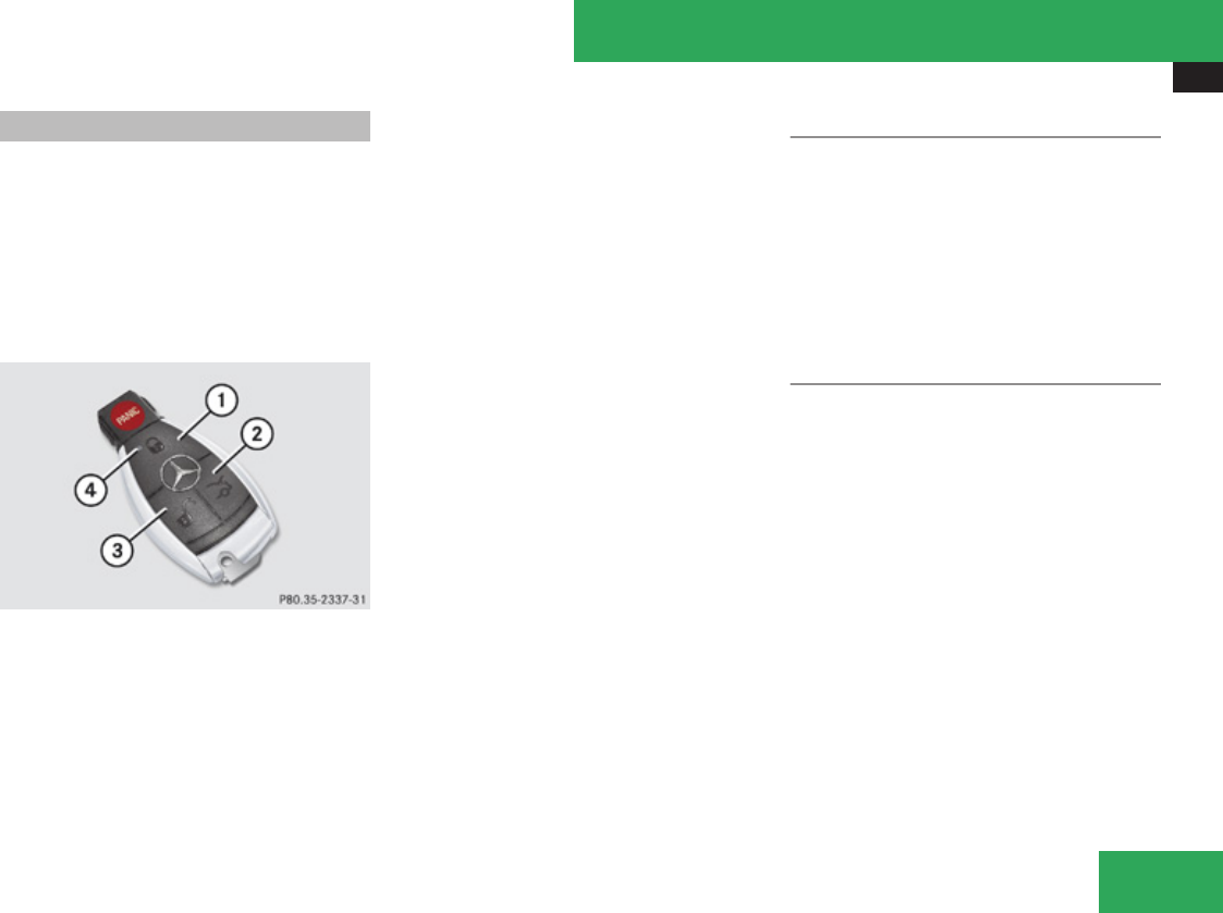
Locking and unlocking
297
SmartKey
Your vehicle comes supplied with two
SmartKeys, each with remote control and a
removable mechanical key.
The SmartKey centrally locks and unlocks:
Rthe doors
Rthe trunk lid
Rthe fuel filler flap
1 jLock button
2 iUnlock button for trunk lid
3 kUnlock button
4Battery check lamp
iUSA only:
This device complies with Part 15 of the
FCC Rules. Operation is subject to the
following two conditions:
1. This device may not cause harmful
interference, and
2. this device must accept any
interference received, including
interference that may cause undesired
operation.
Any unauthorized modification to this
device could void the user’s authority to
operate the equipment.
iCanada only:
This device complies with RSS-210 of
Industry Canada. Operation is subject to
the following two conditions:
1. This device may not cause interference,
and
2. this device must accept any
interference received, including
interference that may cause undesired
operation of the device.
Any unauthorized modification to this
device could void the user’s authority to
operate the equipment.
Factory setting
XGlobal unlocking: Press button k.
The vehicle will lock again automatically
and rearm the anti-theft alarm system
within approximately 40 seconds of
unlocking if neither door nor trunk is
opened.
XGlobal locking: Press button j.
Selective setting
If you frequently travel alone, you may wish
to reprogramm the SmartKey so that pressing
button k only unlocks the driver’s door
and the fuel filler flap.
XSwitching on/off: Press and hold buttons
k and j simultaneously for
approximately 6 seconds until battery
check lamp 4 (Y page 297) flashes twice.
The SmartKey will then function as follows:
XUnlocking driver’s door and fuel filler
flap: Press button k once.
XGlobal unlocking: Press button k
twice.
XGlobal locking: Press button j.
Controls in detail
Z

Locking and unlocking
298
KEYLESS-GO
Vehicles equipped with KEYLESS-GO come
with two SmartKeys with KEYLESS-GO, each
with remote control and a removable
mechanical key.
The KEYLESS-GO function is integrated into
the SmartKey. The validity of the SmartKey is
checked every time you grasp an outside door
handle.
When the SmartKey is valid, your vehicle
unlocks
Rthe doors
Rthe fuel filler flap
Rthe trunk lid
iUSA only:
This device complies with Part 15 of the
FCC Rules. Operation is subject to the
following two conditions:
1. This device may not cause harmful
interference, and
2. this device must accept any
interference received, including
interference that may cause undesired
operation.
Any unauthorized modification to this
device could void the user’s authority to
operate the equipment.
iCanada only:
This device complies with RSS-210 of
Industry Canada. Operation is subject to
the following two conditions:
1. This device may not cause interference,
and
2. this device must accept any
interference received, including
interference that may cause undesired
operation of the device.
Any unauthorized modification to this
device could void the user’s authority to
operate the equipment.
Important notes on using KEYLESS-GO
RYou can also use the SmartKey with
KEYLESS-GO like a normal SmartKey
(Y page 297).
RYou can combine KEYLESS-GO functions
with normal SmartKey functions (e.g.
unlocking with KEYLESS-GO and locking
with button j).
RAlways carry the SmartKey with you.
RNever store the SmartKey together with:
-Electronic items such as a mobile phone
or another SmartKey
-Metallic objects such as coins or metal
foil
Doing so could impair the function of the
KEYLESS-GO system.
RTo lock or unlock the vehicle, the SmartKey
must be located outside the vehicle within
approximately 3 ft (1 m) of a door or the
trunk.
RIf the vehicle has been parked for more
than 72 hours, you must pull an outside
door handle in order to activate the
KEYLESS-GO function.
RIf the SmartKey is positioned farther away
from the vehicle, the system may no longer
recognize the SmartKey. The vehicle
cannot be locked or the engine started via
the KEYLESS-GO system.
RIf the SmartKey is removed from the vehicle
(e.g. if a passenger exits the vehicle with
the SmartKey)
-when pressing the KEYLESS-GO start/
stop button or trying to lock the vehicle
with the outside door handle the
Controls in detail
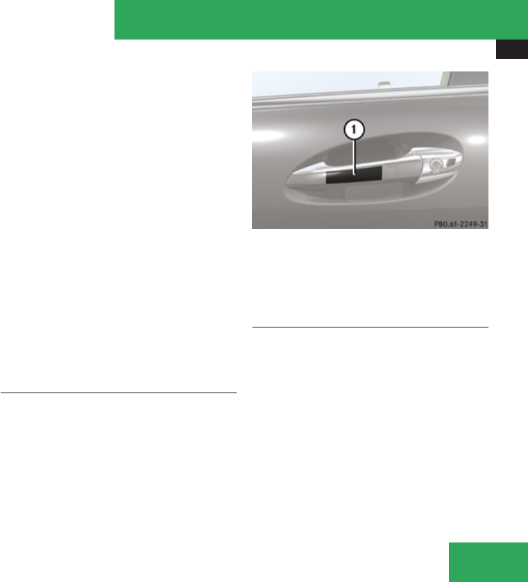
Locking and unlocking
299
message Key Not Detected appears in
the multifunction display
-with the engine running, the message
Key Not Detected appears in the
multifunction display while driving off
Find the SmartKey or change its present
location immediately (e.g. place it on the
front passenger seat or insert it in shirt
pocket).
RIf you have started the engine with the
KEYLESS-GO start/stop button, you can
turn it off again by
-pressing the KEYLESS-GO start/stop
button
-inserting the SmartKey into the starter
switch when the vehicle is at a standstill
and the automatic transmission is in park
position P
RThe vehicle could be inadvertently
unlocked if the SmartKey is within 3 ft (1 m)
of the vehicle and
-an outside door handle is splashed with
water
or
-you attempt to clean an outside door
handle
RRemember that the engine can be started
by anyone with a SmartKey that is left
inside the vehicle.
Possibility 1 (One SmartKey in the vehicle,
one SmartKey outside the vehicle):
If you leave the SmartKey behind when
exiting and locking the vehicle, no message
appears in the multifunction display.
Possibility 2 (One SmartKey in the vehicle,
no SmartKey outside the vehicle):
When exiting and trying to lock the vehicle,
the message Key Detected In Vehicle
appears in the multifunction display. The
vehicle will not be locked.
Factory setting
XGlobal unlocking: Pull an outside door
handle.
The vehicle will lock again automatically
and rearm the anti-theft alarm system
within approximately 40 seconds if neither
door nor trunk is opened.
1Outside door handle
XGlobal locking: Touch outside of door
handle 1.
Selective setting
If you frequently travel alone, you may wish
to reprogram the SmartKey so when you pull
the driver’s outside door handle, only the
driver’s door and the fuel filler flap unlock.
XSwitching on/off: Press and hold buttons
k and j simultaneously for
approximately 6 seconds until battery
check lamp 4 (Y page 297) flashes twice.
The SmartKey will then function as follows:
Controls in detail
Z

Locking and unlocking
300
XUnlocking driver’s door and fuel filler
flap: Pull the driver’s outside door handle.
XGlobal unlocking: Pull any outside door
handle other than the driver’s outside door
handle.
XGlobal locking: Touch outside of door
handle 1.
Checking SmartKey batteries
XPress button j or k on the
SmartKey.
Battery check lamp 4 (Y page 297) comes
on briefly to indicate that the SmartKey
batteries are in order.
If the battery check lamp does not come on
briefly during check, the SmartKey batteries
are discharged.
XReplace the batteries (Y page 564).
iYou can obtain the required batteries at
any authorized Mercedes-Benz Center.
iIf the batteries are checked within signal
range of the vehicle, pressing button
j or k will lock or unlock the vehicle
accordingly.
Loss of the SmartKey
If you lose your SmartKey or mechanical key,
you should do the following:
XHave the SmartKey deactivated by an
authorized Mercedes-Benz Center.
XReport the loss of the SmartKey or the
mechanical key to your car insurance
company immediately.
XHave the mechanical lock replaced if
necessary.
Any authorized Mercedes-Benz Center will be
glad to supply you with a replacement.
Opening the doors from the inside
You can open a locked door from the inside.
Open door only when conditions are safe to
do so.
Example illustration driver’s door
1Locking knob
2Inside door handle
If the vehicle has previously been locked with
the SmartKey or with KEYLESS-GO, opening
a door from the inside will trigger the anti-
theft alarm system.
To cancel the alarm, see (Y page 80).
Controls in detail
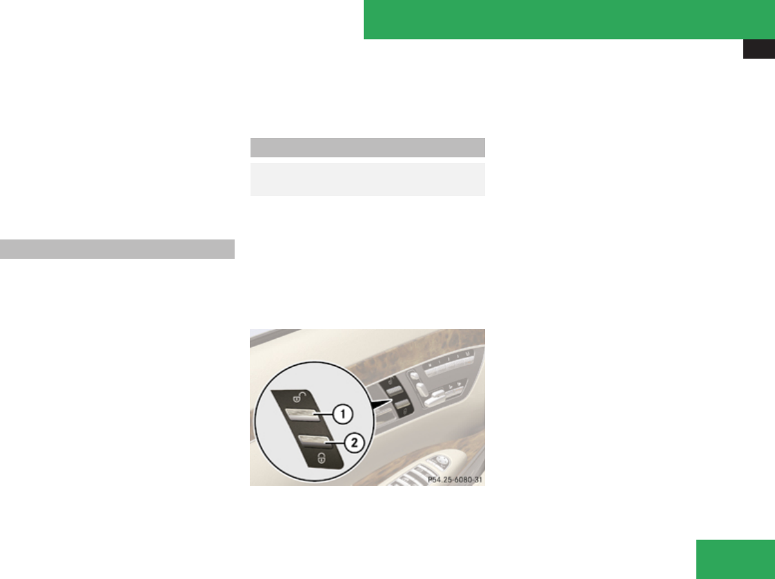
Locking and unlocking
301
XFront doors: Pull on inside door handle
2 on the respective front door to open
door.
If the door was locked, locking knob 1 will
move up.
XRear doors: Pull up locking knob on the
respective rear door to unlock door.
XPull on inside door handle on the respective
rear door to open door.
Automatic central locking
The doors and the trunk lock automatically
when the vehicle is set into motion.
You can open a locked door from the inside.
Open door only when conditions are safe to
do so.
The doors are designed to unlock
automatically after an accident if the force of
the impact exceeds a preset threshold.
The vehicle locks automatically when the
ignition is switched on and the wheels are
turning at vehicle speeds of approximately
9 mph (15 km/h) or more. You could
therefore lock yourself out when the vehicle
is pushed or towed or is on a test stand.
You can deactivate the automatic central
locking using the COMAND system
(Y page 222).
Locking and unlocking from the inside
GObserve Safety notes, see
page 62.
You can lock or unlock the vehicle from inside
using the central locking switches. This can
be useful, for example, if you want to lock the
vehicle before starting to drive.
The central locking switches do not lock or
unlock the fuel filler flap or the interior
storage compartments, such as the glove
box.
1Central unlocking switch
2Central locking switch
XLocking: Press central locking switch 2.
If the front passenger door is closed, the
vehicle locks.
XUnlocking: Press central unlocking switch
1.
You can open a locked door from inside at any
time. Open door only when conditions are
safe to do so.
If the vehicle was previously locked with the
central locking switch:
Rand the SmartKey is set to factory settings,
the complete vehicle is unlocked when a
door is opened from the inside
Rand the SmartKey is set to selective
settings, only the door opened from inside
is unlocked
If the vehicle was previously locked centrally
with the SmartKey or with KEYLESS-GO, it will
not unlock using the central unlocking switch.
Controls in detail
Z
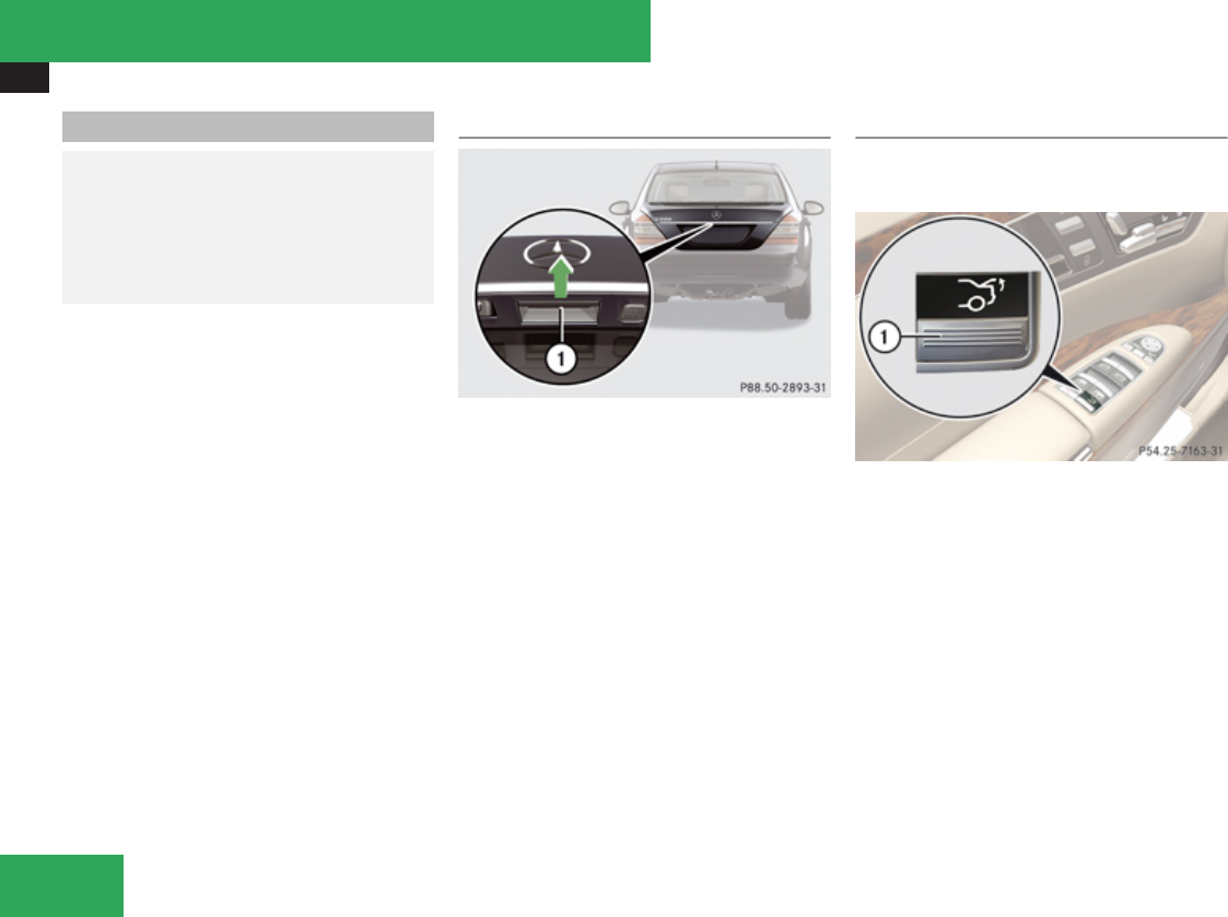
Locking and unlocking
302
Opening the trunk
GWarning!
Make sure the trunk is closed when the
engine is running and while driving. Among
other dangers, deadly carbon monoxide
(CO) gases may enter vehicle interior
resulting in unconsciousness and death.
You can open the trunk when the vehicle is
stationary.
A minimum height clearance of 5.90 ft
(1.80 m) is required to open the trunk lid.
! The trunk lid swings open upwards
automatically. Always make sure there is
sufficient overhead clearance.
Opening the trunk from the outside
1Handle
XPress and hold button i on the
SmartKey until the trunk unlocks and
begins to open.
or
XPull on handle 1.
In vehicles without KEYLESS-GO: The
vehicle must be unlocked.
If the trunk does not open, it is still locked
separately (Y page 306).
Vehicles with trunk opening/closing system:
XStopping the opening procedure: Press
button i on the SmartKey.
Opening the trunk from the inside
Vehicles without trunk opening/closing
system
1Remote trunk opening switch
XPress and hold switch 1 until the trunk
begins to open.
Controls in detail
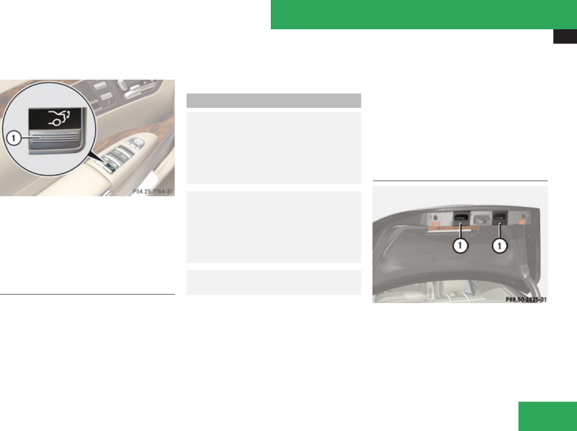
Locking and unlocking
303
Vehicles with trunk opening/closing
system
1Remote trunk opening/closing switch
XPress and hold switch 1 until the trunk
begins to open.
XTo interrupt the opening procedure:
Press switch 1.
Trunk opening-height restriction
Vehicles with trunk opening/closing system:
The trunk lid opening height can be limited
when transporting goods on a roof rack (e.g.
presence of an optional MB sport luggage
container). When activated, the trunk opens
to approximately the height of the roof edge.
XActivating: Use the COMAND system
(Y page 226).
Closing the trunk
GWarning!
Make sure the trunk is closed when the
engine is running and while driving. Among
other dangers, deadly carbon monoxide
(CO) gases may enter vehicle interior
resulting in unconsciousness and death.
GWarning!
To prevent possible personal injury, always
keep hands and fingers away from the trunk
opening when closing the trunk lid. Be
especially careful when small children are
around.
GObserve Safety notes, see
page 62.
Do not leave the SmartKey in the open trunk.
You may lock yourself out.
If the vehicle was previously centrally locked
with the SmartKey or KEYLESS-GO, the trunk
lid will lock automatically when closed. All
turn signal lamps flash three times to confirm
locking.
Vehicles with KEYLESS-GO:
To prevent a possible inadvertent lockout, the
trunk lid will open automatically if a SmartKey
with KEYLESS-GO is recognized inside the
vehicle or in the trunk.
The vehicle is only locked when the turn signal
lamps flash three times. If you are carrying a
second SmartKey with KEYLESS-GO with you,
you can still lock the vehicle.
Closing the trunk from the outside
manually
1Handles
XLower trunk lid by pulling firmly on handles
1.
XClose trunk with hands placed flat on trunk
lid.
Controls in detail
Z
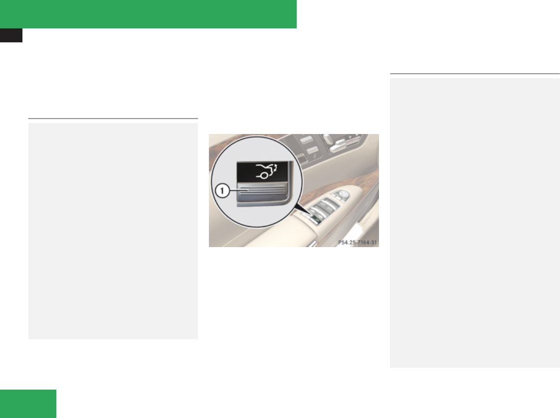
Locking and unlocking
304
The power closing assist automatically
ensures that the trunk lid is pulled completely
close (Y page 307).
Closing the trunk from the inside
automatically
GWarning!
Maintain sight of the area around the rear
of the vehicle while operating the trunk lid
with the door mounted switch. Monitor the
closing procedure carefully to make sure no
one is in danger of being injured.
To interrupt the closing procedure, release
the door mounted remote trunk opening/
closing switch again.
Even with the SmartKey removed from the
starter switch or the SmartKey with
KEYLESS-GO removed from the vehicle, the
remote trunk opening/closing switch can
be operated. Therefore, do not leave
children unattended in the vehicle, or with
access to an unlocked vehicle. A child’s
unsupervised access to a vehicle could
result in an accident and/or serious
personal injury.
In vehicles with trunk opening/closing
system you can close the trunk from the
inside using the remote trunk opening/
closing switch.
If the trunk lid comes into contact with an
object while closing (e.g. luggage that has
been piled too high) in the upper motion
sequence, the closing procedure is stopped
and the trunk reopens slightly.
1Remote trunk opening/closing switch
XPress and hold switch 1 until the trunk is
closed.
To interrupt the closing procedure:
XRelease switch 1.
Closing the trunk from the outside
automatically
GWarning!
Monitor the closing procedure carefully to
make sure no one is in danger of being
injured. To prevent possible personal
injury, always keep hands and fingers away
from the trunk opening when closing the
trunk lid. Be especially careful when small
children are around. To stop the closing
procedure, do one of the following:
RPress button i on the SmartKey.
RPress the remote trunk opening/closing
switch (on the driver’s door).
RPress the trunk closing switch.
RPress the KEYLESS-GO locking/closing
switch.
RPull the trunk lid handle.
Even with the SmartKey removed from the
starter switch or the SmartKey with
KEYLESS-GO removed from the vehicle, the
remote trunk opening/closing switch can
be operated. Therefore, do not leave
children unattended in the vehicle, or with
access to an unlocked vehicle. A child’s
unsupervised access to a vehicle could
Controls in detail
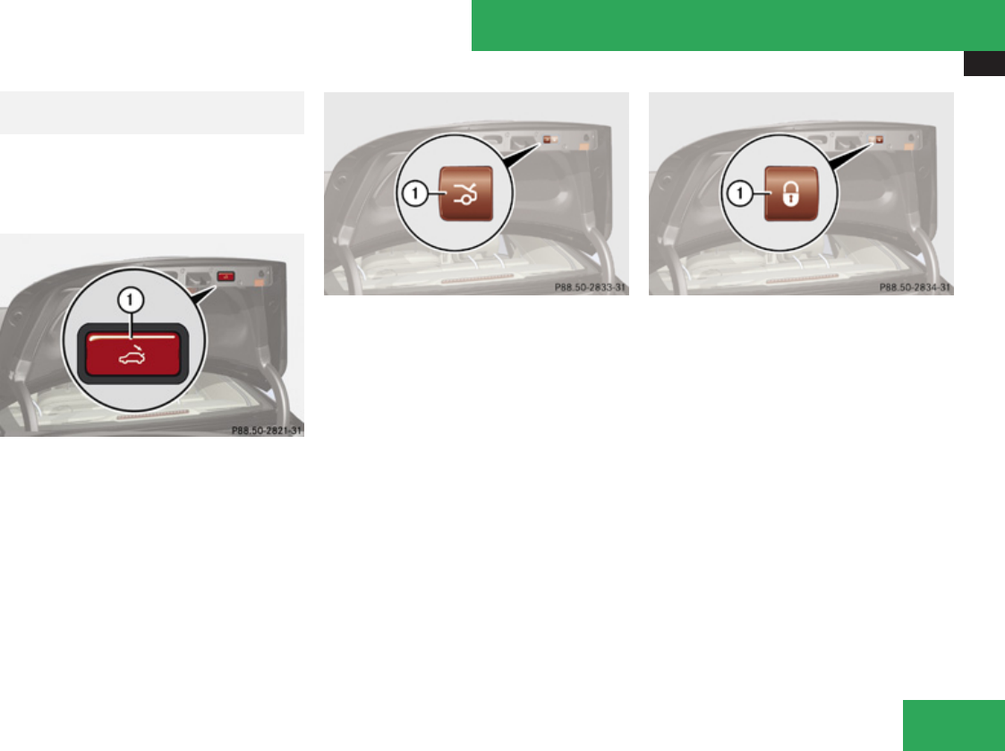
Locking and unlocking
305
result in an accident and/or serious
personal injury.
In vehicles with trunk opening/closing
system you can close the trunk separately
from the outside using the trunk closing
switch.
Vehicles without KEYLESS-GO
1Trunk closing switch
Vehicles with KEYLESS-GO
1Trunk closing switch
XPress switch 1 briefly.
If the trunk lid comes into contact with an
object while closing (e.g. luggage that has
been piled too high) in the upper motion
sequence, the closing procedure is stopped
and the trunk lid reopens slightly.
Closing the trunk and locking vehicle from
outside
In vehicles with trunk opening/closing
system and KEYLESS-GO, you can close the
trunk and lock the vehicle simultaneously
from the outside using the KEYLESS-GO
locking/closing switch.
1KEYLESS-GO locking/closing switch
XMake sure you have the SmartKey with
KEYLESS-GO with you.
XPress switch 1 briefly.
With all doors closed:
RThe locking knobs in the doors move
down.
RThe trunk lid starts to close
automatically.
RAll turn signal lamps flash three times to
confirm locking once the trunk has
closed completely.
RAn acoustic signal sounds three times (if
equipped and feature activated).
RThe anti-theft alarm system is armed.
If the trunk lid comes into contact with an
object while closing (e.g. luggage that has
Controls in detail
Z
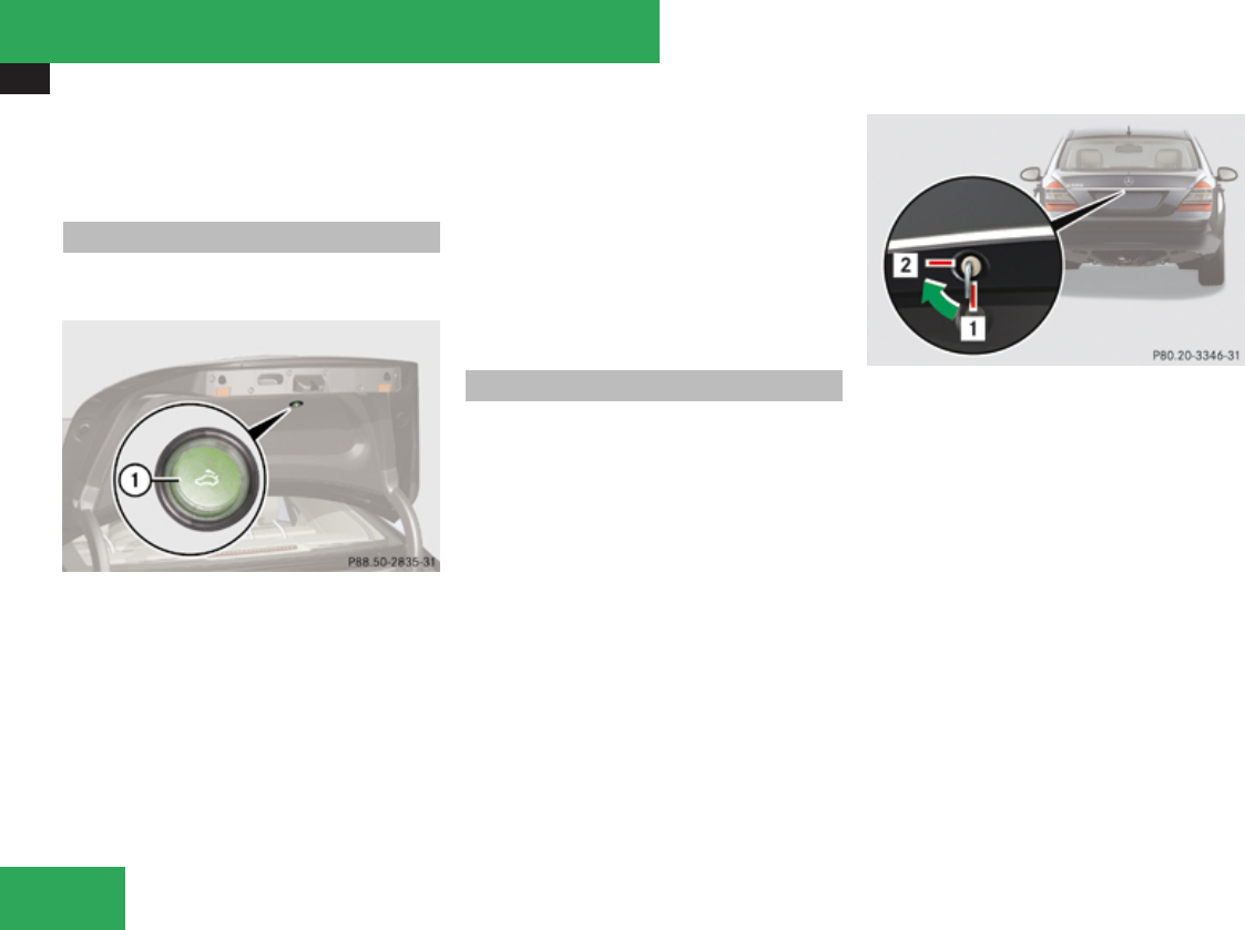
Locking and unlocking
306
been piled too high) in the upper motion
sequence, the closing procedure is stopped
and the trunk lid reopens slightly.
Trunk lid emergency release
With the emergency release button, the trunk
lid can be opened from inside the trunk.
1Emergency release button
XBriefly press emergency release button
1.
The trunk lid unlocks and opens.
The emergency release button unlocks and
opens the trunk while the vehicle is standing
still or in motion.
Illumination of the emergency release button:
RThe button flashes for 30 minutes after
opening the trunk.
RThe button flashes for 60 minutes after
closing the trunk.
The emergency release button does not open
the trunk, if the vehicle battery is discharged
or disconnected.
Valet locking
To deny any unauthorized person access to
the trunk, e.g. when you valet park the
vehicle, lock it separately with the mechanical
key. Leave only the SmartKey less its
mechanical key with the vehicle.
$Neutral position
%Locked
XValet locking: Close the trunk.
XRemove the mechanical key from the
SmartKey (Y page 561).
XInsert the mechanical key in the trunk lid
lock.
XTurn the mechanical key clockwise to
position % and remove the mechanical
key in that position to lock the trunk.
The trunk remains locked even when the
vehicle is centrally unlocked.
You can only cancel the separate trunk
locking mode by means of the mechanical
key.
Controls in detail

Starter switch positions
307
XCanceling: Insert the mechanical key in
the trunk lid lock.
XTurn the mechanical key counterclockwise
to neutral position $ and remove the
mechanical key in that position to unlock
the trunk.
You can now open the trunk.
Power closing assist for doors and
trunk lid
It is not necessary to slam the door or trunk
lid closed. An electrical power-assisted
mechanism draws doors and trunk lid closed
quietly and automatically once door and trunk
lid has been latched. When the electrical
power-assisted mechanism has stopped,
doors and/or trunk can be reopend.
GWarning!
To prevent possible personal injury, always
keep hands and fingers away from the door
or trunk opening when closing a door or the
trunk lid. Be especially careful when small
children are around.
In case of danger, pull the inside or outside
door handle, or pull the trunk lid handle.
To prevent personal injury, never actuate
the closing assist mechanism by tampering
with the door or trunk lid latch.
GWarning!
Only drive with the doors closed.
Otherwise, one or more of the doors could
open while the vehicle is in motion, putting
you and/or others at risk.
GWarning!
Make sure the trunk is closed when the
engine is running and while driving. Among
other dangers, deadly carbon monoxide
(CO) gases may enter vehicle interior
resulting in unconsciousness and death.
XPower closing assist for doors: Press the
doors gently past the initial engage position
into the lock.
XPower closing assist for trunk lid: Press
the trunk lid gently into its lock.
Starter switch positions
SmartKey
GObserve Safety notes, see
page 62.
Starter switch
}For removing SmartKey
$Power supply for some electrical
consumers, e.g. radio
%Ignition (power supply for all electrical
consumers) and driving position
&Starting position
When you switch on the ignition, all lamps
(except high-beam headlamp indicator lamp,
and turn signal indicator lamps unless
activated) in the instrument cluster come on.
If a lamp in the instrument cluster fails to
come on when the ignition is switched on,
Controls in detail
Z
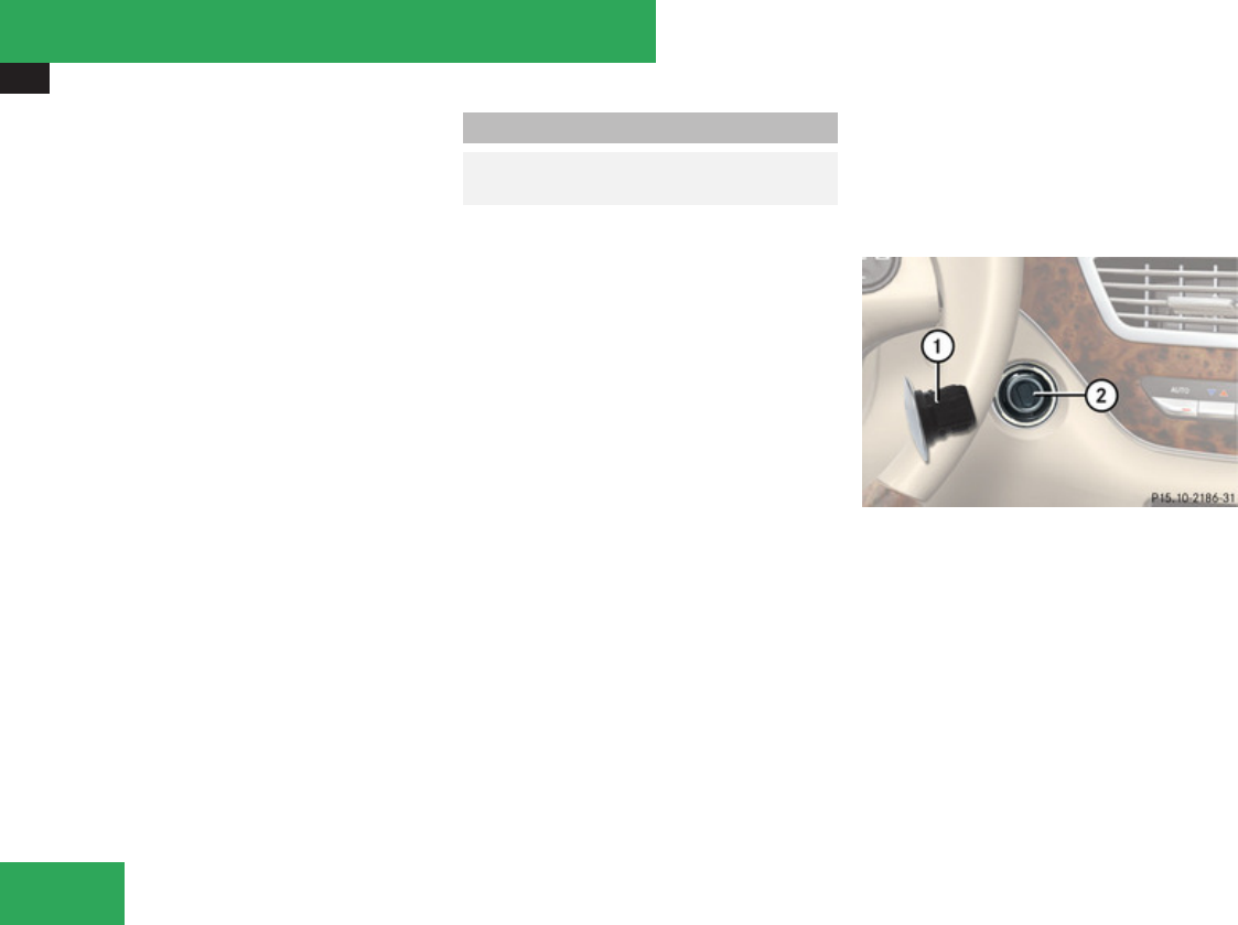
Starter switch positions
308
have it checked and replaced if necessary. If
a lamp in the instrument cluster remains on
after starting the engine or comes on while
driving, refer to “Lamps in instrument
cluster” (Y page 548).
! If the SmartKey cannot be turned in the
starter switch, the vehicle battery may not
be sufficiently charged.
RCheck the vehicle battery and charge it
if necessary.
RGet a jump start.
To prevent accelerated vehicle battery
discharge or a completely discharged
vehicle battery, always remove the
SmartKey from the starter switch when the
engine is not in operation.
KEYLESS-GO
GObserve Safety notes, see
page 62.
Vehicles equipped with the KEYLESS-GO
feature are supplied with a SmartKey with
integrated KEYLESS-GO function and a
removable KEYLESS-GO start/stop button.
With the KEYLESS-GO start/stop button
inserted in the starter switch and the
SmartKey present in the vehicle, pressing the
KEYLESS-GO start/stop button
Rwithout the brake pedal depressed
corresponds to the various starter switch
positions (Y page 307)
Rwith the brake pedal firmly depressed will
start the engine (Y page 338)
If you wish or should there be the need to
insert the SmartKey in the starter switch, the
KEYLESS-GO start/stop button can be easily
removed by pulling it out of the starter switch.
iThe KEYLESS-GO start/stop button does
not need to be removed from the starter
switch when you leave the vehicle.
However, always take the SmartKey with
you when you leave the vehicle. As long as
the SmartKey is in the vehicle, the vehicle’s
electrical systems can be switched on or
the engine can be started using the
KEYLESS-GO start/stop button.
The function of the SmartKey overrules the
KEYLESS-GO function.
The SmartKey must be located in the vehicle.
1KEYLESS-GO start/stop button
2Starter switch
XInsert KEYLESS-GO start/stop button 1
into starter switch 2 (if not inserted
already).
iWhen you switch from SmartKey mode
back to KEYLESS-GO mode, the system
requires 2 seconds of detection time
before you can use the KEYLESS-GO button
as usual.
Controls in detail
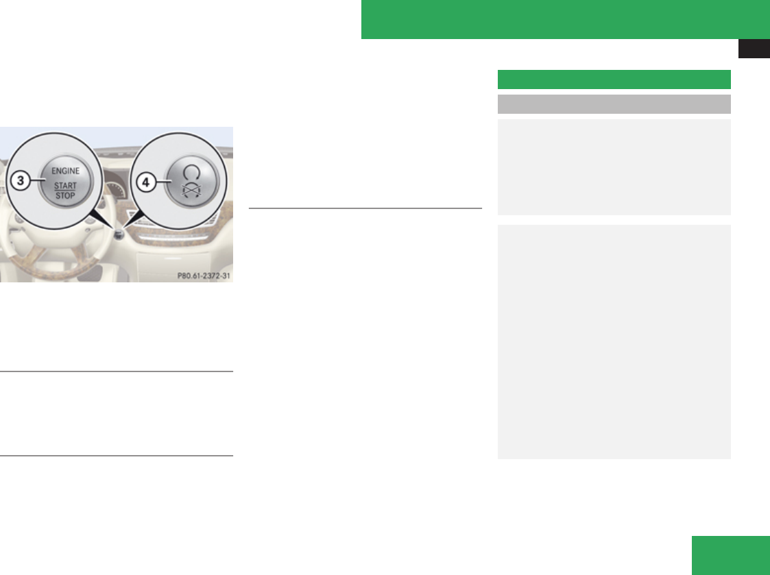
Seats
309
XMake sure the automatic transmission is in
park position P.
XDo not depress the brake pedal.
KEYLESS-GO start/stop button
=USA only
?Canada only
Position 0
Before you press the KEYLESS-GO start/stop
button, the vehicle’s on-board electronics
have status 0 (as with SmartKey removed).
Position 1
XPress the KEYLESS-GO start/stop button
once.
This supplies power for some electrical
consumers, such as radio functions.
iIf you now press the KEYLESS-GO start/
stop button
Ronce more, the ignition (position 2) is
switched on
Rtwice more the power supply is again
switched off
Ignition (or position 2)
XPress the KEYLESS-GO start/stop button
twice.
This supplies power for all electrical
consumers.
All lamps (except high-beam headlamp
indicator lamp and turn signal indicator
lamps unless activated) in the instrument
cluster come on. If a lamp in the instrument
cluster fails to come on when the ignition
is switched on, have it checked and
replaced if necessary. If a lamp in the
instrument cluster remains on after
starting the engine or comes on while
driving, refer to “Lamps in instrument
cluster” (Y page 548).
iIf you now press the KEYLESS-GO start/
stop button once, the power supply is again
switched off.
Seats
Safety notes
GWarning!
In order to avoid possible loss of vehicle
control, all seat, head restraint, steering
wheel, and rear view mirror adjustments, as
well as fastening of seat belts, must be
done before the vehicle is put into motion.
GWarning!
Do not adjust the driver’s seat while driving.
Adjusting the seat while driving could cause
the driver to lose control of the vehicle.
Never ride in a moving vehicle with the seat
backrest in an excessively reclined position
as this can be dangerous. You could slide
under the seat belt in a collision. If you slide
under it, the seat belt would apply force at
the abdomen or neck. That could cause
serious or fatal injuries. The seat backrest
and seat belts provide the best restraint
when the wearer is in a position that is as
upright as possible and seat belts are
properly positioned on the body.
Controls in detail
Z

Seats
310
GWarning!
Your seat must be adjusted so that you can
correctly fasten your seat belt.
Observe the following points:
RAdjust the seat backrest until your arms
are slightly angled when holding the
steering wheel.
RAdjust the seat to a comfortable seating
position that still allows you to reach the
accelerator/brake pedal safely. The
position should be as far back as possible
with the driver still able to operate the
controls properly.
RAdjust the head restraint so that it is as
close to the head as possible and the
center of the head restraint supports the
back of the head at eye level.
RNever place hands under the seat or near
any moving parts while a seat is being
adjusted.
Failure to do so could result in an accident
and/or serious personal injury.
GWarning!
The power seats can be operated at any
time. Therefore, do not leave children
unattended in the vehicle, or with access to
an unlocked vehicle. A child’s unsupervised
access to a vehicle could result in an
accident and/or serious personal injury.
GWarning!
According to accident statistics, children
are safer when properly restrained in the
rear seating positions than in the front
seating position. Thus, we strongly
recommend that children be placed in the
rear seats whenever possible. Regardless
of seating position, children 12 years old
and under must be seated and properly
secured in an appropriately sized infant
restraint, toddler restraint, or booster seat
recommended for the size and weight of the
child. For additional information, see
“Children in the vehicle”.
A child’s risk of serious or fatal injuries is
significantly increased if the child restraints
are not properly secured in the vehicle
and/or the child is not properly secured in
the child restraint.
GWarning!
For your protection, drive only with properly
positioned head restraints.
Adjust the head restraint so that it is as
close to the head as possible and the center
of the head restraint supports the back of
the head at eye level. This will reduce the
potential for injury to the head and neck in
the event of an accident or similar situation.
Do not drive the vehicle without the seat
head restraints. Head restraints are
intended to help reduce injuries during an
accident.
Seat adjustment
You can adjust the lumbar support,
multicontour seats for driver and front
passenger, as well as drive-dynamic
multicontour seats using COMAND
(Y page 233).
! When moving the seats, make sure there
are no items in the footwell or behind the
seats. Otherwise, you could damage the
seats.
Controls in detail
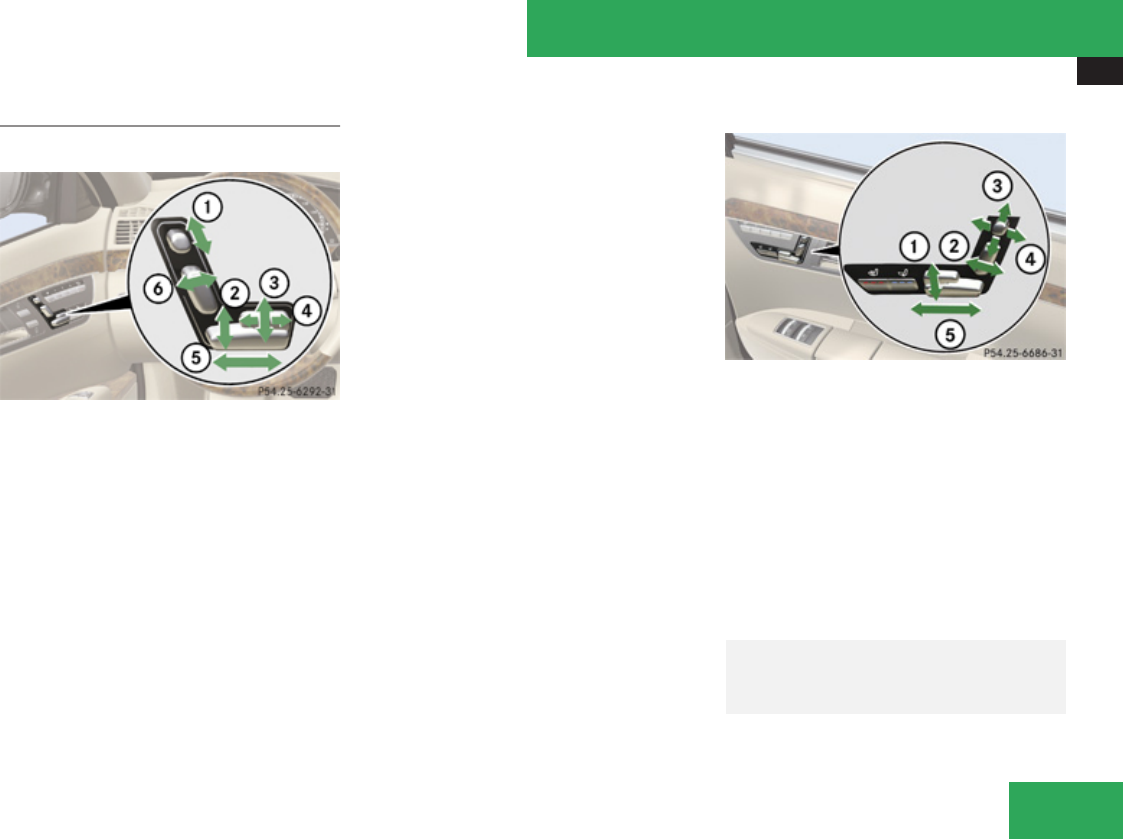
Seats
311
Power seats
Front power seats
1Head restraint height
2Seat height
3Seat cushion tilt
4Seat cushion depth
5Seat fore and aft adjustment
6Seat backrest tilt
iIf PRE-SAFE® has been activated, the
front passenger’s seat and/or electrically
adjustable rear seats will be moved to a
more favorable seat position.
iThe memory function (Y page 323) lets
you store the settings for the seat position
together with the settings for the steering
wheel and the exterior rear view mirrors.
XSeat height: Press the switch up or down
in direction of arrow 2.
XSeat cushion tilt: Press the switch up or
down in direction of arrow 3 until your
upper legs are lightly supported.
XSeat cushion depth: Press the switch
forward or backward in direction of arrow
4 until your legs are supported
comfortably.
XSeat fore and aft: Press the switch
forward or backward in direction of arrow
5.
iWhen moving the seat fore or aft, the head
restraints may readjust automatically.
XSeat backrest tilt: Press the switch
forward or backward in direction of arrow
6.
XHead restraint height: Press the switch
up or down in direction of arrow 1.
Rear power seats (rear outer seats)
1Seat cushion tilt
2Seat backrest tilt
3Folding down and placing upright head
restraint (Y page 316)
4Head restraint tilt
5Seat fore and aft adjustment
XAdjust desired seat using seat switches
1, 2 and 5.
Adjusting front passenger seat from
driver’s seat/rear
GWarning!
When adjusting the front passenger seat,
make sure the seat, if occupied, is as far
Controls in detail
Z
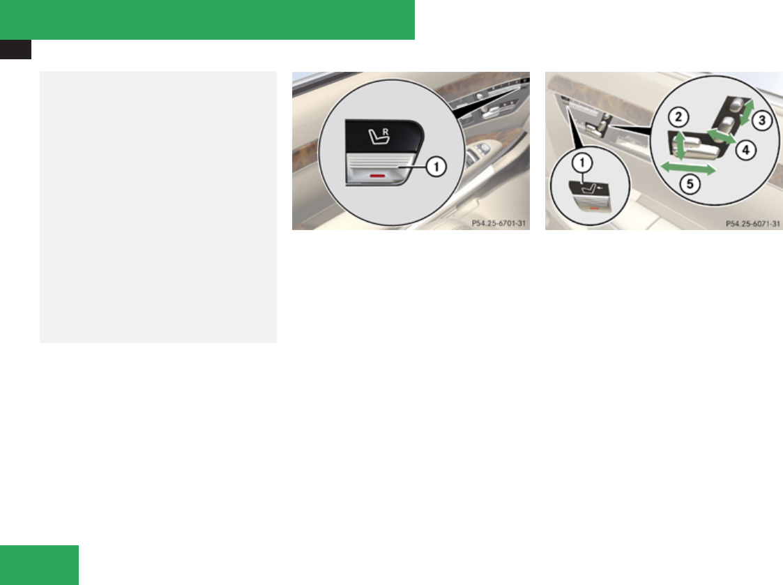
Seats
312
from the front passenger front air bag as
possible.
Otherwise, the passenger could be
seriously or even fatally injured in the event
of an accident or braking maneuver.
Make sure no one is caught or injured while
the seat is being adjusted.
Even with the SmartKey or SmartKey with
KEYLESS-GO removed from the starter
switch or the SmartKey with KEYLESS-GO
removed from the vehicle, the power seats
can be operated. Therefore, do not leave
children unattended in the vehicle, or with
access to an unlocked vehicle. A child’s
unsupervised access to a vehicle could
result in an accident and/or serious
personal injury.
! Do not move the front passenger seat
completely forward if objects are stored in
the parcel net in the front passenger-side
footwell. Items in the net may be damaged.
Adjusting front passenger seat from
driver’s seat
You can adjust the front passenger seat using
the seat switches on the driver’s side.
1Selector button for front passenger seat
XPress button 1.
When the indicator lamp in button 1 is on,
you can operate the following features of the
front passenger seat:
Rseat adjustment
Rseat heating/ventilation
Rmemory function
Setting front passenger seat position
from rear
The button is located on the right rear
passenger door.
1Selector button for front or rear
passenger seat
2Seat height
3Head restraint height
4Backrest tilt
5Seat fore and aft
XPress button 1 to adjust the front
passenger seat.
The indicator lamp in button 1 comes on.
XAdjust front passenger seat using seat
switches 2, 3, 4 and 5.
XTo adjust right rear passenger seat, press
button 1 again.
The indicator lamp in button 1 goes out.
iAdjusting the passenger seat position
from the rear is not possible if you have
deactivated the functions in the rear
Controls in detail
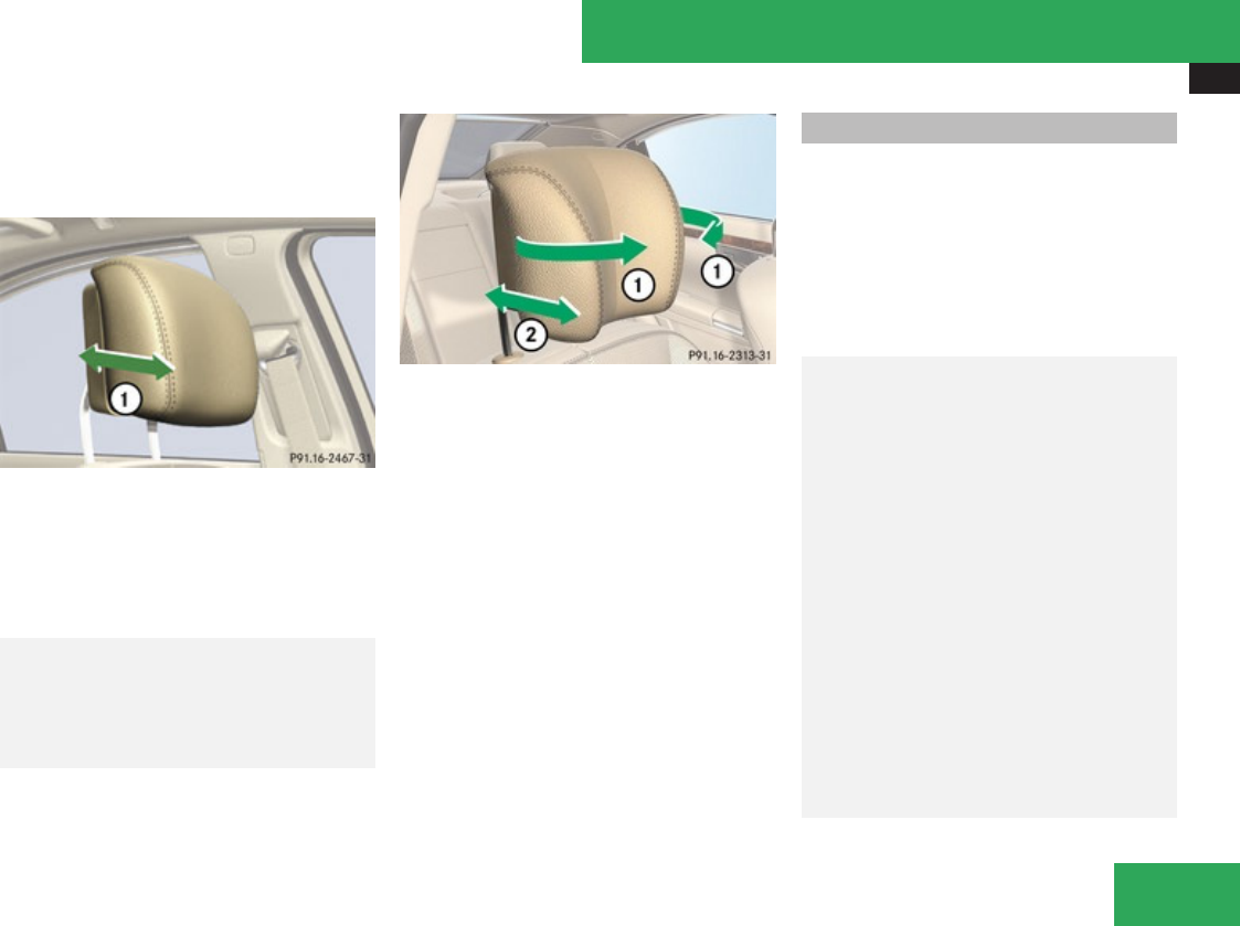
Seats
313
passenger compartment with the override
switch (Y page 67).
Head restraint fore and aft adjustment
1Adjusting head restraint
XAdjust the head restraint to the desired
position by pushing or pulling on the upper
edge of the head restraint cushion.
Comfort head restraint
GWarning!
When folding back the side cushions, never
reach between the side cushion and the
mounting post. You could otherwise be
trapped.
1Side cushions
2Fore and aft adjustment
You can individually adjust the side cushions
of the head restraints.
XAdjusting side cushions: Pull or push side
cushions 1 into desired position.
XAdjusting forward or backward: Pull or
push head restraint in direction of arrow
2.
Easy-entry/exit feature
This feature allows for easier entry into and
exit from the vehicle. When entering and
exiting the vehicle, the driver’s seat is in its
maximum rearward position and the steering
wheel is in its uppermost position.
The easy-entry/exit feature can be activated
or deactivated in the Vehicle menu of the
COMAND system (Y page 223).
GWarning!
You must make sure no one can become
trapped or injured by the moving steering
wheel and driver’s seat when the easy-
entry/exit feature is activated.
To stop seat/steering wheel movement, do
one of the following:
RPress seat adjustment switch
RMove steering wheel adjustment stalk
RPress one of the memory position
buttons or the memory button M
Do not leave children unattended in the
vehicle, or with access to an unlocked
vehicle. Children could open the driver’s
door and unintentionally activate the easy-
entry/exit feature, which could result in an
accident and/or serious personal injury.
Controls in detail
Z

Seats
314
! Do not activate the easy-entry/exit
feature if the seat backrest is in an
excessively reclined position. Doing so
could cause damage to front or rear seats.
First move the seat backrest to an upright
position.
With the easy-entry/exit feature activated,
the steering wheel and driver’s seat will
return to their last set memory position or a
factory-set maximum forward position when
you:
Rclose the driver’s door with the ignition
switched on
Rinsert the SmartKey into the starter switch
or press the KEYLESS-GO start/stop
button once with the driver’s door closed
iFor safety reasons, the driver’s seat will
not return to its last set position with the
easy-entry/ exit feature activated if the
system recognizes the last set position as
an extreme forward position. Instead, the
driver’s seat will remain at or move to a
factory-set maximum forward position. To
again fully return the driver’s seat to your
last set position or to memory position,
adjust the seat to the desired position or
press and hold the respective memory
position button (Y page 323).
iThe last set driver’s seat and steering
wheel positions are stored when the
ignition is switched off and the position is
stored in memory.
With the easy-entry/exit feature activated
the steering wheel tilts upwards and the
driver’s seat moves a few inches to the rear
when you:
Rremove the SmartKey from the starter
switch,
or
Ropen the driver’s door with the SmartKey in
starter switch position 0 or 1 or the
KEYLESS-GO start/stop button in position
1
iIf the current position for the steering
wheel is in the uppermost tilt position, the
steering wheel will no longer be able to
move upward when the easy-entry/exit
feature is activated.
If the current seat position falls into a
factory-set position range and the system
recognizes the current seat position to be
rearward enough for easy entry and exit,
the driver’s seat will not move to the rear
when the easy-entry/ exit feature is
activated.
The adjustment procedure is briefly
interrupted when the engine is started.
GWarning!
Let the system complete the adjustment
procedure before setting the vehicle in
motion. All driver’s seat and steering wheel
adjustments must be completed before
setting the vehicle in motion. Driving off
with the driver’s seat/steering wheel still
adjusting could cause the driver to lose
control of the vehicle.
Rear seat head restraints
GWarning!
For safety reasons, always drive with the
rear head restraints in the upright position
when the rear seats are occupied.
Keep the area around head restraints clear
of articles (e.g. clothing) to not obstruct the
folding operation of the head restraints.
GWarning!
For your protection, drive only with properly
positioned head restraints.
Adjust the head restraint in such a way that
it is as close to the head as possible and the
Controls in detail
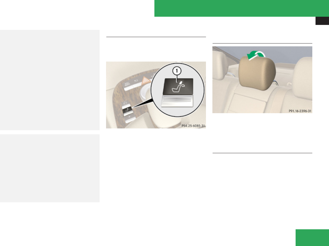
Seats
315
center of the head restraint supports the
back of the head at eye level. This will
reduce the potential for injury to the head
and neck in the event of an accident or
similar situation.
With a rear seat occupied, make sure to
move the respective head restraint up from
the lowest non-use position and have the
occupant adjust the head restraint
properly.
Do not drive the vehicle without the seat
head restraints installed when the rear
seats are occupied. Head restraints are
intended to help reduce injuries during an
accident.
GWarning!
Make sure the rear seat head restraints
engage when placing them upright
manually. Otherwise their protective
function cannot be ensured.
The back of the head will not be supported
in the event of a collision. That could cause
serious or even fatal injuries. Rear seat
occupants can be seriously injured or
killed.
Folding rear seat head restraints back
The rear seat head restraints and the rear
seat power head restraints can be folded
backward for increased visibility.
1Head restraint release switch
XSwitch on the ignition.
XPress switch 1 in the front center console
briefly.
The head restraints will fold backward.
Placing rear seat head restraints
upright
XPull the head restraint forward until it locks
into position.
Placing power rear seat head restraints
upright (rear outer seats)
iWhen you fasten your seat belt in the rear,
the respective rear outer seat head
restraint places upright automatically.
Controls in detail
Z
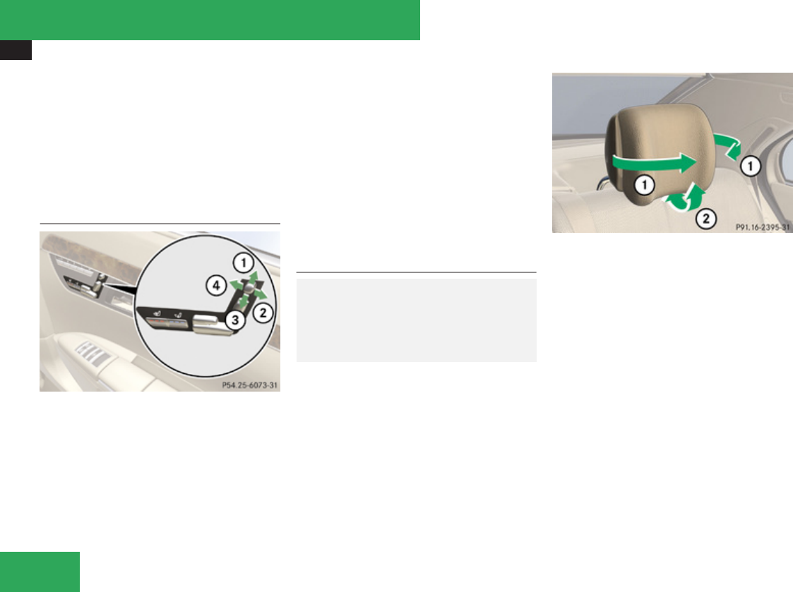
Seats
316
XSwitch on the ignition.
XPress and hold switch 1 (Y page 315) in
the front center console.
The rear seat head restraints will fold up.
XPull the rear center seat head restraint
upright manually until it locks into position.
Power rear seat head restraints (rear
outer seats)
1Placing upright head restraint
2Head restraint tilt
3Folding down head restraint
4Head restraint tilt
XPress switch up in direction of arrow 1.
The head restraint will move to an upright
position.
XPress switch down in direction of arrow
3.
The head restraint will fold down.
XPress the switch forward or backward in
direction of arrow 2 or 4.
The head restraint will be tilted.
Comfort rear seat head restraints (rear
outer seats)
GWarning!
When folding back the side cushions, never
reach between the side cushion and the
mounting post. You could otherwise be
trapped.
1Side cushions
2Head restraint tilt
XAdjusting side cushions: Pull or push side
cushions 1 into desired position.
XAdjusting head restraint angle: Push or
pull on the lower edge of the head restraint
cushion in direction of arrow 2.
Controls in detail
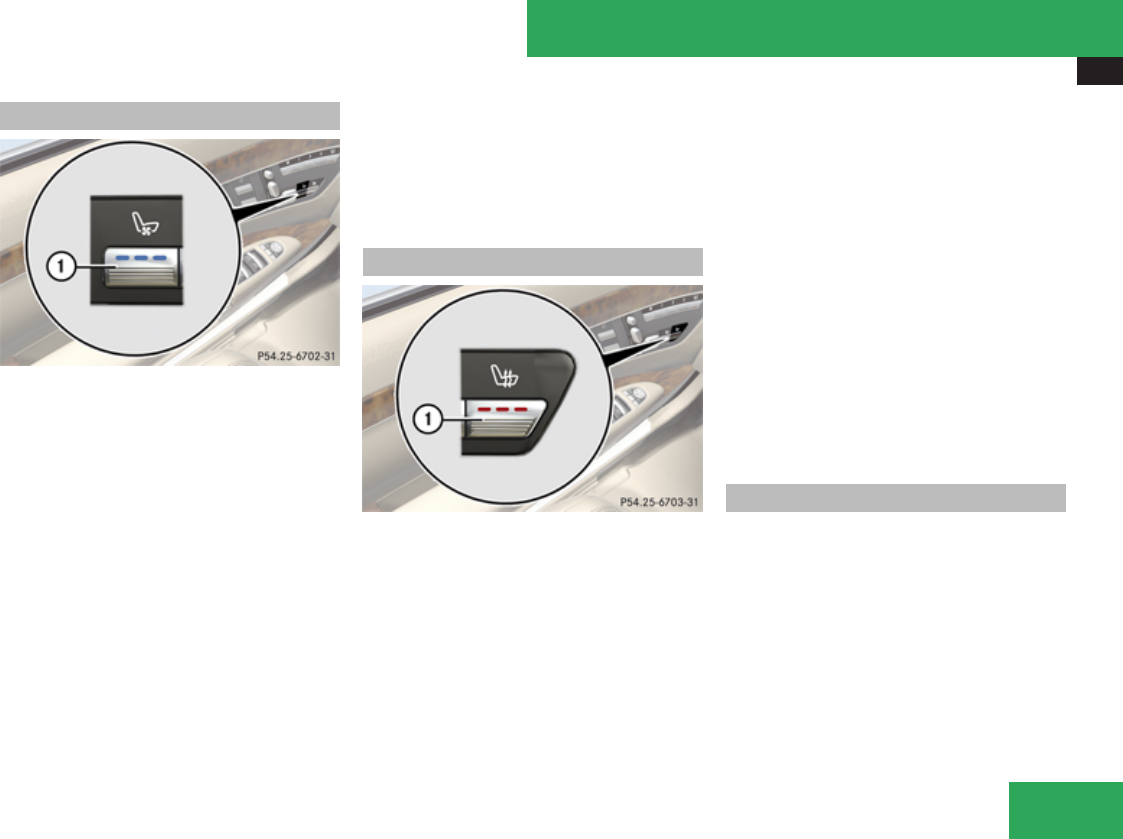
Seats
317
Seat ventilation
1Seat ventilation button
The blue indicator lamps in the button come
on to show which ventilation level you have
selected.
iThe seat ventilation for the driver’s seat
can be activated using summer opening
feature (Y page 336).
XSwitch on the ignition.
XSwitching on: Press button 1 repeatedly
until the desired ventilation level is set.
XSwitching off: Press button 1 repeatedly
until all indicator lamps go out.
If one or more of the indicator lamps in the
seat ventilation button 1 are flashing, there
is insufficient voltage available since too
many electrical consumers are turned on. The
seat ventilation switches off automatically.
The seat ventilation will switch back on again
automatically as soon as sufficient voltage is
available.
Seat heating
1Seat heating button
The red indicator lamps in button 1 come on
to show which heating level you have
selected.
The seat heating switches from level 3 (high)
to level 2 after approximately 5 minutes.
The seat heating switches from level 2 to level
1 (low) after approximately 10 minutes.
The seat heating automatically switches off
from level 1 after approximately 20 minutes.
XSwitch on the ignition.
XSwitching on: Press button 1 repeatedly
until the desired heating level is set.
One or more red indicator lamps in button
1 show the selected heating level.
XSwitching off: Press button 1 repeatedly
until all indicator lamps go out.
If one or more of the indicator lamps in seat
heating button 1 are flashing, there is
insufficient voltage available since too many
electrical consumers are turned on. The seat
heating switches off automatically.
The seat heating will switch back on again
automatically as soon as sufficient voltage is
available.
Multicontour seats, rear
You can adjust the rear outer multicontour
seats using the buttons on the center
console.
Controls in detail
Z
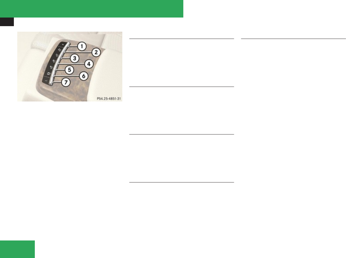
Seats
318
1To select right rear passenger seat
2Massage setting, gentle
3Massage setting, vigorous
4To adjust position of seat backrest
curvature (lordosis)
5Lumbar region support
6Side bolster adjustment
7To select left rear passenger seat
XSelecting a seat: Press rocker switch 1
or 7 forward or backward.
The indicator lamp in the selected rocker
switch lights up for a short while.
Gentle massage
XSwitching on: Press rocker switch 2
forward.
XSwitching off: Pull rocker switch 2
backward.
Vigorous massage
XSwitching on: Press rocker switch 3
forward.
XSwitching off: Pull rocker switch 3
backward.
Position of seat backrest curvature
XMoving upward: Press rocker switch 4
forward.
XMoving downward: Pull rocker switch 4
backward.
Lumbar region support
XSelecting greater curvature: Press
rocker switch 5 forward.
XSelecting less curvature: Pull rocker
switch 5 backward.
Side bolster adjustment
XReducing width: Press rocker switch 6
forward.
XIncreasing width: Pull rocker switch 6
backward.
Controls in detail
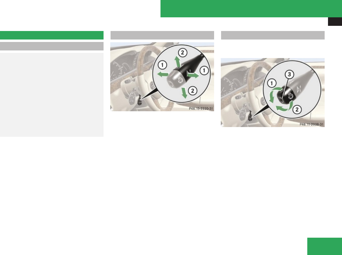
Multifunction steering wheel
319
Multifunction steering wheel
Safety notes
GWarning!
Do not adjust the steering wheel while
driving. Adjusting the steering wheel while
driving could cause the driver to lose
control of the vehicle.
The electrical steering wheel adjustment
feature can be operated at any time.
Therefore, do not leave children
unattended in the vehicle, or with access to
an unlocked vehicle. A child’s unsupervised
access to a vehicle could result in an
accident and/or serious personal injury.
Make sure
Ryou can reach the steering wheel with your
arms slightly bent at the elbows
Ryou can move your legs freely
Rall displays (including malfunction and
indicator lamps) on the instrument cluster
are clearly visible
Steering wheel adjustment
1Adjusting steering wheel, in or out
2Adjusting steering wheel, up or down
XAdjusting steering wheel in or out: Move
stalk in direction of arrows 1.
XAdjusting steering wheel up or down:
Move stalk in direction of arrows 2.
iThe memory function (Y page 323) lets
you store the settings for the steering
wheel together with the settings for the
seat position and the exterior rear view
mirrors.
Heated steering wheel
The steering wheel heating warms up the
leather area of the steering wheel.
1Switching on
2Switching off
3Indicator lamp
XSwitch on the ignition.
XSwitching on: Turn switch at the tip of the
stalk in direction of arrow 1.
Indicator lamp 3 comes on.
iThe steering wheel heating will not switch
on, when the temperature of the vehicle
interior is above 86‡ (30†).
XSwitching off: Turn switch at the tip of
stalk in direction of arrow 2.
Indicator lamp 3 goes out.
Controls in detail
Z
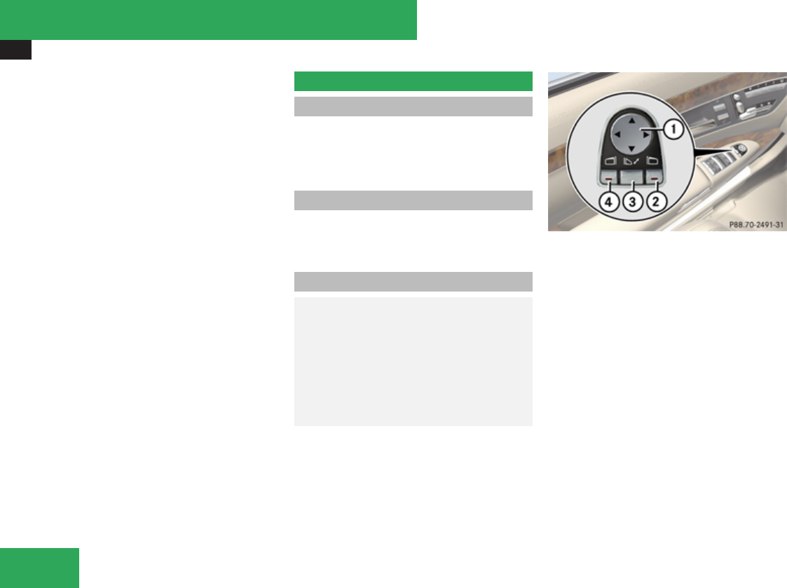
Mirrors
320
iIndicator lamp 3 flashes or goes out in
case of power surge or undervoltage or if
the steering wheel heating malfunctions.
iThe steering wheel heating switches off
automatically:
Rwhen you remove the SmartKey from the
starter switch
Ron vehicles with KEYLESS-GO, when you
switch off the ignition and open the
driver’s door
Rwhen the temperature of the vehicle
interior is above 86‡ (30†)
Rafter approximately 24 minutes
For more information on the steering wheel,
see “Multifunction steering
wheel” (Y page 237).
Mirrors
Notes
Adjust the interior and exterior rear view
mirrors before driving so that you have a good
view of the road and traffic conditions.
Interior rear view mirror
XAdjust the interior rear view mirror
manually.
Exterior rear view mirrors
GWarning!
Exercise care when using the passenger-
side exterior rear view mirror. The mirror
surface is convex (outwardly curved
surface for a wider field of view). Objects in
mirror are closer than they appear. Check
your interior rear view mirror and glance
over your shoulder before changing lanes.
1Adjustment button
2Passenger-side exterior rear view mirror
button
3Button for folding exterior rear view
mirrors in and out
4Driver’s side exterior rear view mirror
button
XSwitch on the ignition.
XPress button 4 for the driver’s side
exterior rear view mirror or button 2 for
the passenger-side exterior rear view
mirror.
The indicator lamp in the respective button
comes on.
XPress adjustment button 1 up, down, left
or right according to the desired setting.
Controls in detail

Mirrors
321
When you press button 1 for the first time,
the exterior mirror on the driver’s side is
always selected.
If you do not make adjustments to the
selected exterior rear view mirror within
15 seconds, the indicator lamp goes out. You
will then have to select the desired exterior
rear view mirror again before adjustments
can be made. Adjustments can only be made
with the indicator lamp for the respective
exterior rear view mirror button illuminated.
! If an exterior rear view mirror was forcibly
hit from the front, manually snap it back
into place.
iAt low ambient temperatures, the exterior
rear view mirrors will be heated
automatically.
Auto-dimming rear view mirrors
The exterior rear view mirror on the driver’s
side and the interior rear view mirror will
respond automatically to glare when the
ignition is switched on and incoming light
from headlamps falls on the sensor in the
interior rear view mirror.
The rear view mirrors will not react if the
automatic transmission is set to reverse gear
R or the interior lighting is switched on.
GWarning!
The auto dimming function does not react
if incoming light is not aimed directly at
sensors in the interior rear view mirror.
The interior rear view mirror and the
exterior rear view mirror on the driver’s side
do not react, for example, if the rear window
sunshade is in raised position.
Light hitting the mirror(s) at certain angles
(incident light) could blind you. As a result,
you may not be able to observe traffic
conditions and could cause an accident.
Power folding exterior rear view
mirrors
! Before you drive the vehicle through an
automatic car wash, fold in the exterior rear
view mirrors. Otherwise they may get
damaged.
Folding in and out automatically
When the corresponding function in the
COMAND system is activated (Y page 222):
RThe exterior rear view mirrors fold in
automatically as soon as the vehicle is
locked from the outside.
RThe exterior rear view mirrors fold out
automatically as soon as the vehicle is
unlocked and the driver’s or front
passenger door are subsequently opened.
Folding in and out manually
iThe mirrors do not fold out if they were
previously folded in manually. Please make
sure both mirrors are folded out before
driving off.
The exterior rear view mirrors can vibrate if
they are not folded out completely.
Controls in detail
Z
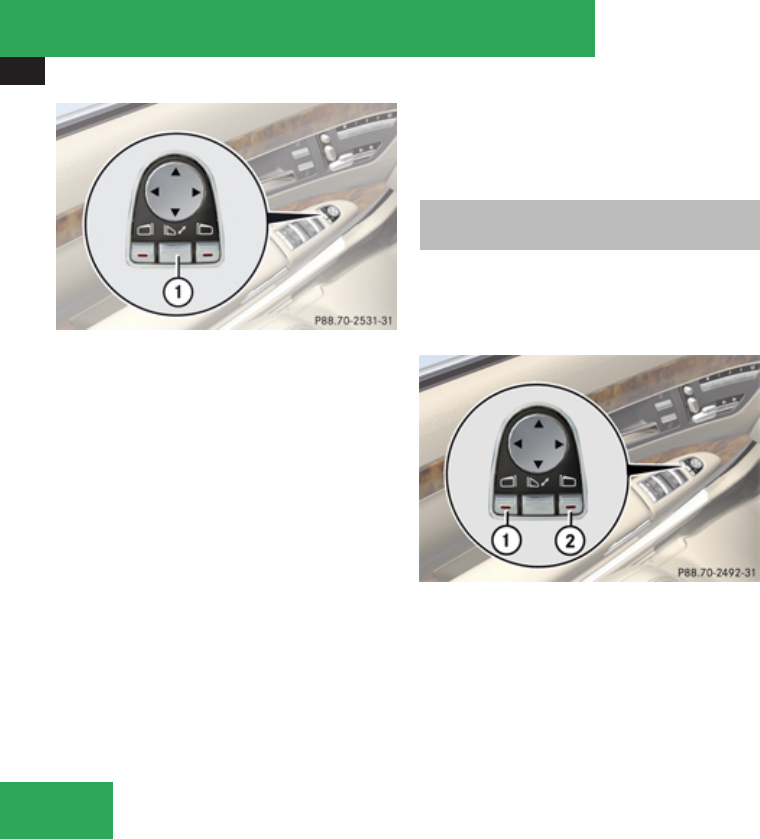
Mirrors
322
1Button for folding exterior rear view
mirrors in and out
XFolding in: Briefly press button 1.
Both exterior rear view mirrors fold in.
XFolding out: Briefly press button 1.
Both exterior rear view mirrors fold out.
! If an exterior rear view mirror housing is
forcibly pushed forward (hit from the rear),
reposition it manually by applying firm
pressure until it snaps back into place.
If an exterior rear view mirror housing is
forcibly pushed rearward (hit from the
front), press button 1 to fold mirrors in,
then press button 1 again to fold mirrors
out. Do not force mirrors by hand as this
may damage the adjustment mechanism.
The mirror housing is then properly
positioned and you can adjust the mirror in
the usual manner.
Activating exterior rear view mirror
parking position
Follow these steps to activate the mirror
parking position so that the passenger-side
exterior rear view mirror will be turned
downward to the stored position.
1Driver’s side exterior rear view mirror
button
2Passenger-side exterior rear view mirror
button
XMake sure you have stored a parking
position for the passenger-side exterior
rear view mirror (Y page 324).
XMake sure the Lower mirror when
reversing function in the Exterior
Mirror Convenience Settings
submenu of the COMAND system is
selected.
XSwitch on the ignition.
XPress button 2 for the passenger-side
exterior rear view mirror.
iWith the automatic transmission in
reverse gear R, the previously selected
exterior rear view mirror is activated.
XShift the automatic transmission into
reverse gear R.
The passenger-side exterior rear view
mirror will be turned downward to the
stored position.
The exterior rear view mirror returns to its
previously stored driving position:
Rwhen you switch off the ignition
R10 seconds after you have put the gear
selector lever out of reverse gear R
Controls in detail
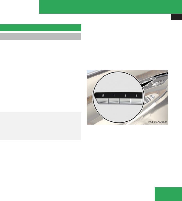
Memory function
323
Rimmediately once your vehicle exceeds a
speed of approximately 6 mph (10 km/h)
Rimmediately when you press button 1 for
driver’s side exterior rear view mirror.
iIf you adjust the exterior mirrors while
they are in the parking position, the new
mirror position is stored as a new parking
position.
Memory function
Notes
With the memory function you can store up
to three different configurations per front
seat.
Each memory position button on the driver’s
side can store all of the following settings:
RSeat position
RMulticontour seat: previously saved setting
RDrive-dynamic multicontour seat:
activation/deactivation
RSteering wheel position
RExterior rear view mirrors’ position
GWarning!
Do not activate the memory function while
driving. Activating the memory function
while driving could cause the driver to lose
control of the vehicle.
Each memory position button on the front
passenger side can store all of the following
settings:
RSeat position
RMulticontour seat: previously saved setting
RDrive-dynamic multicontour seat:
activation/deactivation
MMemory button
1, 2, 3 Memory position button
Controls in detail
Z
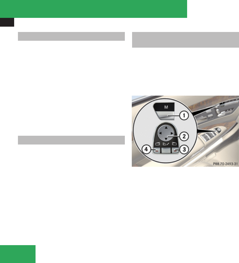
Memory function
324
Storing positions into memory
XAdjust the seats.
XOn the driver’s side, additionally adjust the
steering wheel and exterior rear view
mirrors to the desired positions.
XPress memory button M.
XRelease memory button M and press
memory position button 1, 2 or 3 within
3 seconds.
When the settings are stored to the
selected position, an acknowledgement
signal sounds.
Recalling positions from memory
XPress and hold desired memory position
button 1, 2 or 3 until the seat has
completely moved to the stored position.
On the driver’s side, also wait for the
steering wheel and exterior rear view
mirrors to move to the stored position.
iReleasing the memory position button
stops movement to the stored positions
immediately.
The multicontour seat and/or lumbar
support will continue to be adjusted.
Storing exterior rear view mirror
parking position
For easier parking, you can adjust the
passenger-side exterior rear view mirror so
that you can see the right rear wheel as soon
as you engage reverse gear R.
For information on activating the parking
position, see (Y page 322).
1Memory button M
2Adjustment button
3Passenger side exterior rear view mirror
button
4Driver’s side exterior rear view mirror
button
XStop the vehicle.
XSwitch on the ignition.
XPress button 3.
The passenger-side exterior rear view
mirror is selected.
XAdjust the passenger-side exterior rear
view mirror with adjustment button 2 so
that you see the rear wheel and the road
curb.
XPress memory button M 1.
XWithin 3 seconds, press bottom of
adjustment button 2.
The parking position is stored if the mirror
does not move.
iIf the mirror does move, repeat the above
steps. After the setting is stored, you can
move the mirror again.
Controls in detail
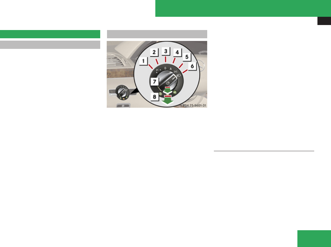
Lighting
325
Lighting
Notes
iIf you drive in countries where vehicles
drive on the other side of the road than the
country where the vehicle is registered, you
must have the headlamps modified for
symmetrical low beams. Relevant
information can be obtained at any
authorized Mercedes-Benz Center.
iThe active Bi-Xenon headlamps monitor
the vehicle’s steering angle and speed,
then automatically shift their beams to
either side to better follow the curvature of
the road ahead, increasing usable
illumination over conventional headlamps.
Exterior lamp switch
$ aStanding lamps, left
% gStanding lamps, right
& MOff
Daytime running lamp mode
( *Automatic headlamp mode
Daytime running lamp mode
) CParking lamps (also tail lamps,
license plate lamps, side marker
lamps and instrument panel lamps)
* BLow-beam headlamps or high-beam
headlamps
, ¥Front fog lamps
. †Rear fog lamp
iThe exterior lamps go out automatically
when you remove the SmartKey from the
starter switch or open the driver’s door with
the ignition switched off.
When the parking lamps or the rear fog
lamp are switched on and you remove the
SmartKey from the starter switch and open
the driver’s door, an acoustic signal
sounds.
In addition, the message Please Switch
Off Lights appears in the multifunction
display.
Switch off the parking lamps or the rear fog
lamp manually.
! Failure to switch off the parking lamps
when leaving the vehicle may result in a
discharged battery.
Low-beam headlamps
The low-beam headlamps can be switched on
and off with the exterior lamp switch.
XSwitch on the ignition.
XSwitching on: Turn the exterior lamp
switch to position B.
The following lamps come on:
RLow-beam headlamps
RTail lamps
RParking lamps
Controls in detail
Z

Lighting
326
RLicense plate lamps
RSide marker lamps
RInstrument panel lamps
RGreen indicator lamp C in the exterior
lamp switch
XSwitching off: Turn the exterior lamp
switch to position M.
Automatic headlamp mode
The following lamps come on and go out
automatically depending on the brightness of
the ambient light:
RLow-beam headlamps
RTail lamps
RParking lamps
RLicense plate lamps
RSide marker lamps
GWarning!
If the exterior lamp switch is set to *,
the headlamps will not automatically come
on under foggy conditions.
To minimize risk to you and to others,
activate headlamps by turning exterior
lamp switch to B when driving or when
traffic and/or ambient lighting conditions
require you to do so.
In low ambient lighting conditions, only
switch from position * to B with the
vehicle at a standstill in a safe location.
Switching from * to B will briefly
switch off the headlamps. Doing so while
driving in low ambient lighting conditions
may result in an accident.
The automatic headlamp feature is only an
aid to the driver. The driver is responsible
for the operation of the vehicle’s lights at
all times.
XSwitching on: Turn the exterior lamp
switch to position *.
With the SmartKey in starter switch
position 1 or the KEYLESS-GO start/stop
button pressed once, the tail and parking
lamps, the license plate lamps and the side
marker lamps will come on and go out
depending on the brightness of the ambient
light.
When the engine is running the low-beam
headlamps, the tail and parking lamps, the
license plate lamps and the side marker
lamps will come on and go out depending
on the brightness of the ambient light.
Canada only: High-beam headlamps are only
available with the exterior lamp switch in
position B.
Daytime running lamp mode
In Canada, the daytime running lamp mode is
mandatory and therefore in a constant mode.
In the USA, the daytime running lamp mode
is deactivated by default. Activate the
daytime running lamp mode using the control
system, see “Setting daytime running lamp
mode (USA only)” (Y page 252).
XTurn the exterior lamp switch to position
M or *.
When the engine is running, the low-beam
headlamps come on.
In low ambient lighting conditions, the
following lamps will come on additionally:
RTail lamps
RParking lamps
RLicense plate lamps
RSide marker lamps
With the daytime running lamp mode
activated and the engine running, you cannot
switch off the low-beam headlamps manually.
Controls in detail

Lighting
327
Canada only
With the exterior lamp switch in position
M or *, you cannot switch on the high-
beam headlamps.
The high-beam flasher is available at all times.
For nighttime driving turn the exterior lamp
switch to position B to permit activation
of the high-beam headlamps.
When the engine is running, and you
Rshift from a driving position to park position
P with the vehicle at a standstill or the
electronic parking brake is engaged, the
low-beam headlamps will go out with a
delay of 3 minutes
Rturn the exterior lamp switch to position
C, the low-beam headlamps, the tail
and parking lamps, the license plate lamps
and the side marker lamps come on
Rturn the exterior lamp switch to position
B, the manual headlamp mode has
priority over the daytime running lamp
mode
The corresponding exterior lamps come on
(Y page 325).
USA only
You can only switch on the high-beam
headlamps in low ambient lighting conditions.
The high-beam flasher is available at all times.
When the engine is running, and you turn the
exterior lamp switch to position C or
B, the manual headlamp mode has
priority over the daytime running lamp mode.
The corresponding exterior lamps come on
(Y page 325).
Fog lamps
Fog lamps cannot be switched on with the
exterior lamp switch in position *. To
switch on the fog lamps, turn the exterior
lamp switch to position B first.
GWarning!
In low ambient lighting or foggy conditions,
only switch from position * to B
with the vehicle at a standstill in a safe
location.
Switching from * to B will briefly
switch off the headlamps. Doing so while
driving in low ambient lighting conditions
may result in an accident.
Fog lamps will operate with the parking lamps
and/or the low-beam headlamps on. Fog
lamps should only be used in conjunction with
low-beam headlamps. Consult your State or
Province Motor Vehicle Regulations
regarding permissible lamp operation.
XSwitch on the ignition.
XTurn the exterior lamp switch to position
C or B (Y page 325).
XSwitching on front fog lamps: Pull out the
exterior lamp switch to first stop.
The green indicator lamp ¥ in the
exterior lamp switch comes on.
XSwitching on rear fog lamp: Pull out the
exterior lamp switch to second stop.
The rear fog lamp, the front fog lamps and
the yellow indicator lamp † in the
exterior lamp switch come on.
XSwitching off front fog lamps/rear fog
lamp: Push in the exterior lamp switch to
its stop.
Locator lighting and night security
illumination
The locator lighting and night security
illumination are described in the COMAND
vehicle menu section under “Locator lighting
on/off” (Y page 221) and “Setting night
security illumination” (Y page 220).
Controls in detail
Z
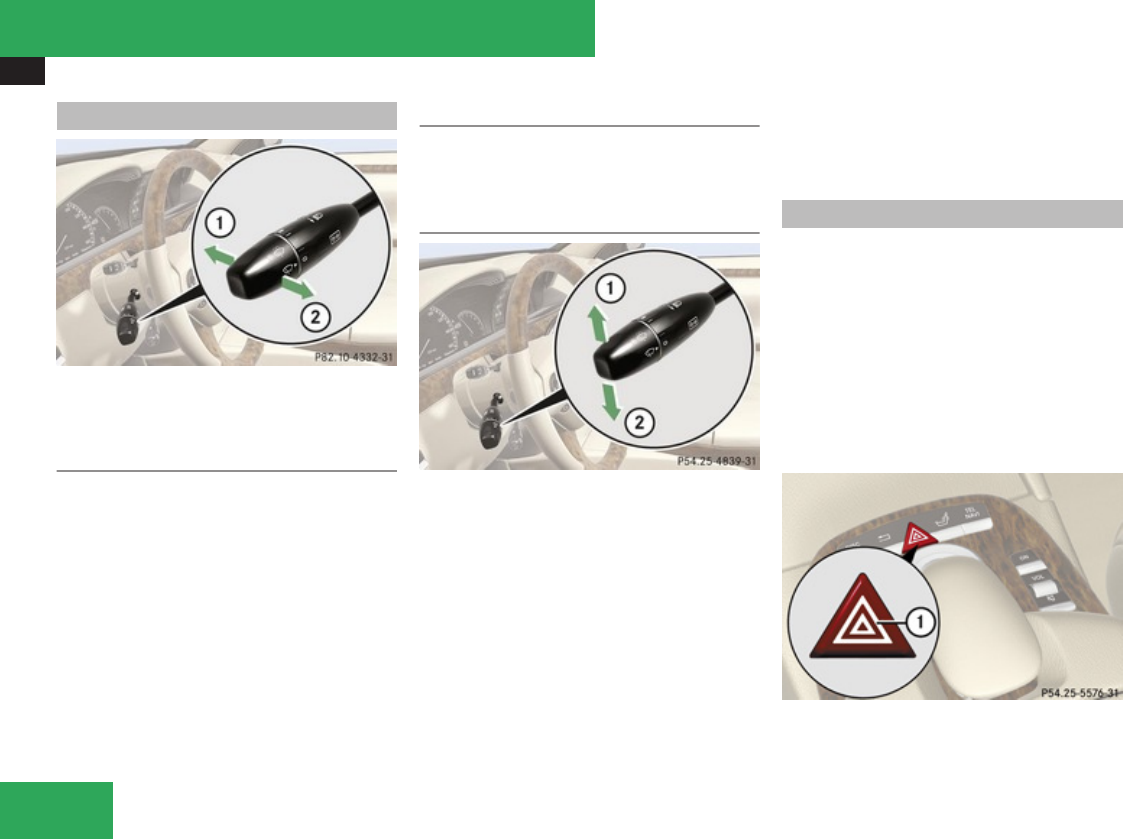
Lighting
328
Combination switch
1High beam
2High-beam flasher
High beam
XTurn the exterior lamp switch to position
B (Y page 325).
XSwitching on: Push the combination
switch in direction of arrow 1.
The high-beam headlamp indicator lamp
A in the instrument cluster comes on.
XSwitching off: Pull the combination switch
in direction of arrow 2 to its original
position.
High-beam flasher
XSwitching on: Pull the combination switch
briefly in direction of arrow 2.
Turn signals
1Turn signals, right
2Turn signals, left
XPress the combination switch in direction
of arrow 1 or 2.
The corresponding turn signal indicator
lamp L or K in the instrument
cluster flashes.
The combination switch resets automatically
after major steering wheel movements.
iTo signal minor directional changes such
as changing lanes, press combination
switch only to point of resistance and
release. The corresponding turn signal
lamps will flash three times.
Hazard warning flasher
The hazard warning flasher can be switched
on at all times, even with the SmartKey
removed from the starter switch.
The hazard warning flasher comes on
automatically when an air bag deploys.
S 600 and S 65 AMG, USA only:
The hazard warning flasher comes on
automatically when you brake the vehicle
strongly at a speed of more than 50 mph
(70 km/h) and bring it to a complete stop.
1Hazard warning flasher switch
Controls in detail

Lighting
329
XSwitching on: Press hazard warning
flasher switch 1.
All turn signal lamps are flashing.
iWith the hazard warning flasher activated
and the combination switch set for either
left or right turn, only the respective left or
right turn signals will operate when the
ignition is switched on.
XSwitching off: Press hazard warning
flasher switch 1 again.
iIf the hazard warning flasher has been
activated automatically, press hazard
warning flasher switch 1 once to switch
off.
Headlamp cleaning system
The headlamps will be cleaned with a high-
pressure water jet automatically when the
engine is running and you have
Rswitched on the headlamps
and
Rthe windshield wipers have wiped the
windshield with washer fluid five times
The counter resets when you switch off the
ignition.
For information on filling up the washer
reservoir, see “Washer system and headlamp
cleaning system” (Y page 448).
Corner-illuminating lamps
The corner-illuminating lamps improve
illumination of the area in the direction into
which you are turning.
The corner-illuminating lamps will only
operate in low ambient lighting conditions.
If you are driving faster than 43 mph
(70 km/h) the corner-illuminating function is
not available.
Switching on
XMake sure the engine is running.
XTurn the exterior lamp switch to position
B or * (Y page 325).
or
XActivate the daytime running lamp mode
(Y page 326).
XSwitch on the left or right turn signal,
depending on whether you are turning left
or right.
The respective corner-illuminating lamp
comes on. If you have switched on the turn
signal for one side but turn the steering
wheel in the other direction, the corner-
illuminating lamp comes on on the side of
the turn signal.
or
XTurn steering wheel in desired direction.
Driving forward: The corner-illuminating
lamp on the side of your steering direction
comes on.
Driving in reverse: The corner-illuminating
lamp opposite to your steering direction
comes on.
The corner-illuminating lamps will come on
automatically depending on the steering
angle, even if you did not switch on either turn
signal. If the corner-illuminating lamps came
on automatically, they will also go out
automatically depending on the steering
angle and vehicle speed.
The corner-illuminating lamps temporarily
come on on both sides of the vehicle if you
turn the steering wheel in one direction and
then again in the other direction shortly
thereafter.
The corner-illuminating lamp may remain lit
for a short time. The corner-illuminating lamp
comes on for no more than 20 seconds with
the vehicle standing still. It then goes out
even if the turn signal is still switched on or if
Controls in detail
Z
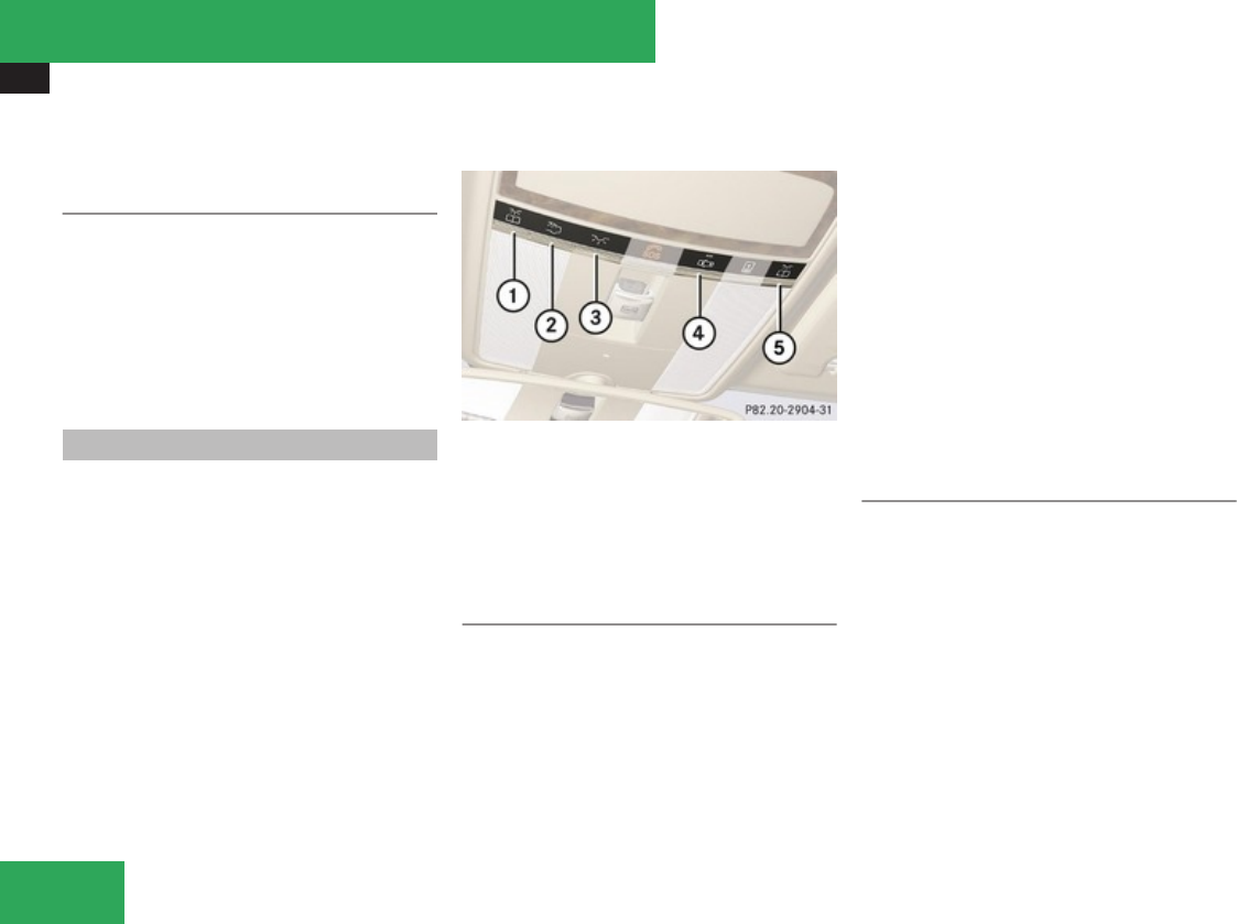
Lighting
330
you have turned the steering wheel to full
lock.
Switching off
XSwitch off the left or right turn signal.
or
XSteer straight ahead.
The corner-illuminating lamp goes out.
iThere may be a brief delay before the
corner-illuminating lamps go out.
Interior lighting in the front
iEven with the SmartKey being removed
from the starter switch you can still use the
lighting for the storage compartment, glove
box and vanity mirrors, when you open a
door or press one of the interior lighting
buttons. If a lamp is switched on and you
do not lock the vehicle, it will be switched
off automatically after 30 minutes.
When you lock the vehicle from the outside,
the interior lighting is switched off.
The interior lighting controls are located in
the overhead control panel.
1X Left front reading lamp on/off
2_ Rear interior lighting on/off
3ð Front interior lighting on/off
4] Automatic control on/off
5X Right front reading lamp on/off
Automatic control
XActivating: Press button ].
The OFF indicator lamp next to the button
goes out.
The interior lighting comes on, when you:
Runlock the vehicle
Rremove the SmartKey from the starter
switch
Ropen a door
XDeactivating: Press button ].
The OFF indicator lamp next to the button
comes on.
The interior lighting goes out after a preset
time (Y page 224).
iIf a door remains open, the interior lamps
go out automatically after approximately
5 minutes.
Manual control
XSwitching on/off front interior
lighting: Press button ð.
XSwitching on/off rear interior lighting:
Press button _.
XSwitching on/off front reading lamps:
Press respective button X.
iThe brightness of the ambient lighting is
adjusted via COMAND (Y page 224).
Controls in detail
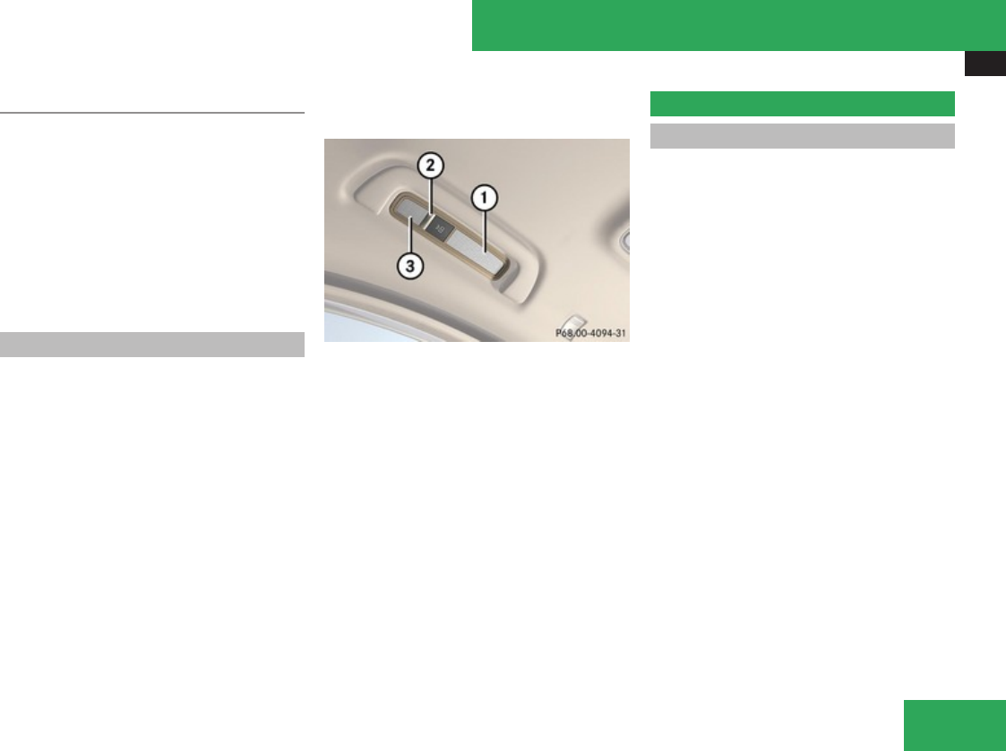
Wipers
331
Emergency lighting
The interior lighting is activated automatically
if the vehicle is involved in an accident.
XSwitching off: Press hazard warning
flasher switch (Y page 328).
or
XPress switch ].
or
XUnlock the vehicle.
Interior lighting in the rear
! An interior lamp switched on manually
does not go out automatically.
Leaving an interior lamp switch in the ON
position for extended periods of time with
the engine turned off could result in a
discharged battery.
The rear reading lamps are located above the
rear door windows.
1Rear interior lamp
2X Rear reading lamp on/off
3Rear reading lamp
XSwitching on/off rear reading lamps:
Press reading lamp switch X.
You can switch the lamps on/off in
succession as follows:
Rrear reading lamp 3 and rear interior
lamp 1 on
Ronly rear reading lamp 3 on
Rrear reading lamp 3 off
Wipers
Notes
! Do not operate the wipers when the
windshield is dry. Dust that accumulates on
a windshield might scratch the glass and/
or damage the wiper blades when wiping
occurs on a dry windshield. If it is necessary
to operate the wipers in dry weather
conditions, always operate the wipers with
washer fluid.
! If the windshield wipers leave smears on
the windshield after the car has been driven
through an automatic car wash, then wax
or other residue is on the windshield.
Shortly after washing the car in an
automatic car wash, clean the windshield
with washer fluid.
Controls in detail
Z
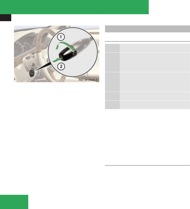
Wipers
332
Combination switch
1Switching on windshield wipers
2Single wipe
Wiping with washer fluid
XSwitch on the ignition.
Windshield wipers
Switching on/off
MWindshield wipers off
USlow intermittent wiping
Rain sensor operation with low
sensitivity.
VFast intermittent wiping
Rain sensor operation with high
sensitivity.
uSlow continuous wiping
tFast continuous wiping
XTurn the combination switch in direction of
arrow 1 to the desired position,
depending on the intensity of the rain.
iWhen the windshield wipers are switched
on and you brake the vehicle to a stop, the
wipers operate more slowly.
Intermittent wiping
Only switch on intermittent wiping under wet
weather conditions or in the presence of
precipitation.
When you select intermittent wiping, the rain
sensor is activated. The rain sensor sets a
suitable wiping interval depending on the
wetness of the sensor surface automatically.
! Do not leave windshield wipers on an
intermittent setting when the vehicle is
taken to an automatic car wash or during
windshield cleaning. Windshield wipers will
operate in the presence of water sprayed
on the windshield, and windshield wipers
may be damaged as a result.
! If you have set intermittent wiping, dirt on
the surface of the rain sensor or optical
effects may cause the windshield wipers to
wipe in an undesired fashion. This could
then damage the windshield wiper blades
or scratch the windshield. You should
therefore switch off the windshield wipers
when weather conditions are dry.
XTurn the combination switch to position
U or V.
After the initial wipe, pauses between
wipes are controlled by the rain sensor
automatically.
Intermittent wiping is interrupted when the
vehicle is at a standstill and a front door is
opened. This protects persons getting into or
out of the vehicle from being sprayed.
Controls in detail

Wipers
333
Intermittent wiping will be continued when all
doors are closed and
Rthe automatic transmission is in drive
position D or reverse gear R
or
Rthe wiper setting is changed using the
combination switch
Single wipe
XPress the combination switch briefly in
direction of arrow 2 to the resistance
point.
The windshield wipers wipe one time
without washer fluid.
Wiping with washer fluid
XPress the combination switch in direction
of arrow 2 past the resistance point.
The windshield wipers operate with washer
fluid.
iTo prevent smears on the windshield or
noisy/chattering wiper blades, wipe with
washer fluid every now and then even when
it is raining.
For information on filling up the washer
reservoir, see “Washer system and headlamp
cleaning system” (Y page 448).
For information on cleaning the headlamps
with washer fluid, see “Headlamp cleaning
system” (Y page 329).
Problems with wipers
! If anything blocks the windshield wipers
(leaves, snow, etc.), switch them off
immediately.
For safety reasons, stop the vehicle in a
safe location, and
R-remove the SmartKey from the starter
switch
or
-turn off the engine by pressing the
KEYLESS-GO start/stop button and
open the driver’s door (with the
driver’s door open, starter switch is in
position 0, same as with SmartKey
removed from starter switch)
-engage the parking brake
before attempting to remove any
blockage.
RRemove blockage.
RTurn the windshield wipers on again.
If the windshield wipers fail to function at
all with the combination switch in position
U or V,
Rset the combination switch to the next
higher wiper speed
Rhave the windshield wipers checked at
the nearest authorized Mercedes-Benz
Center
Controls in detail
Z
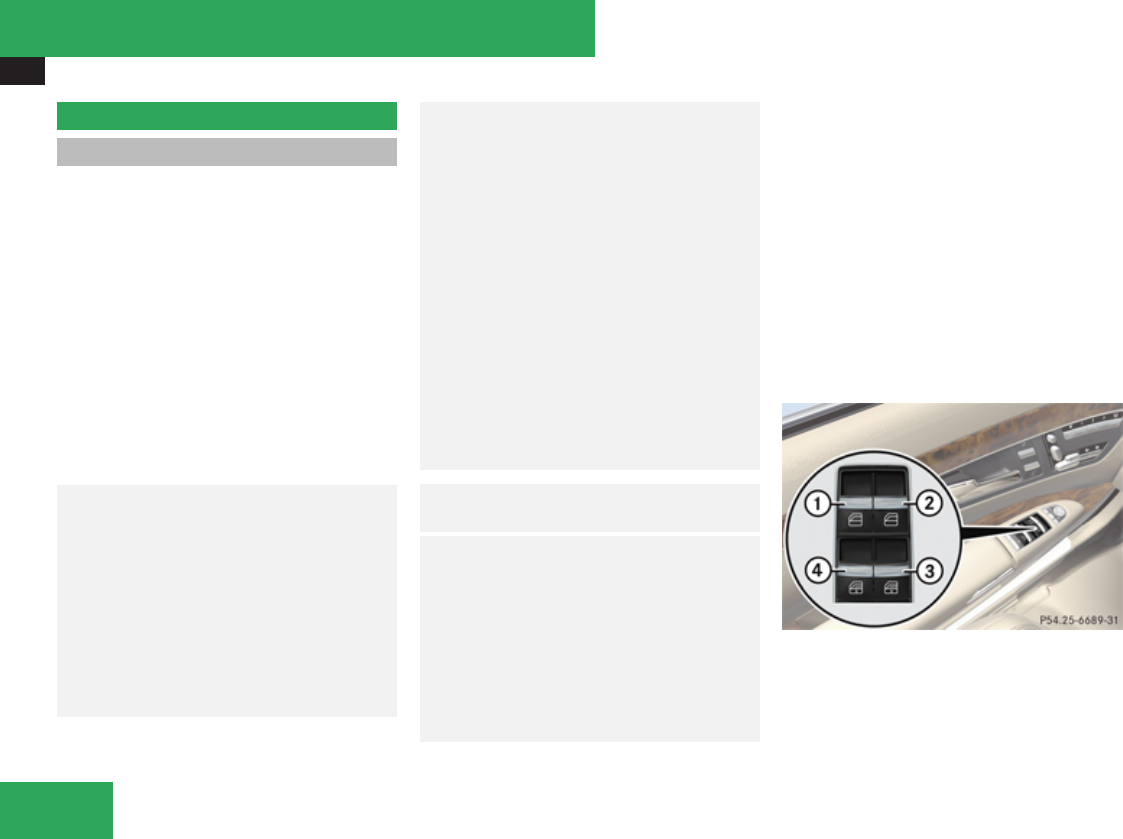
Power windows
334
Power windows
Opening and closing
The door windows are opened and closed
electrically. The switches for all door windows
are located on the driver’s door control panel.
The switches for the respective door windows
are located on the front passenger door and
on the rear doors.
i Operating the rear door windows from
the rear is not possible when you activate
the override switch (Y page 67).
Vehicles equipped with the PRE-SAFE®
system: If the vehicle is in a critical dynamic
driving situation, the door windows close until
only a small gap remains.
GWarning!
When opening or closing the door windows,
make sure there is no danger of anyone
being harmed by the opening/closing
procedure.
The door windows are equipped with the
express operation and automatic reversal
function. If in express operation mode a
door window encounters an obstruction
that blocks its path, the automatic reversal
function will stop the door window and
open it slightly.
The door windows operate differently when
the switch is pressed and held. See the
“Closing when a door window is blocked”
section in this chapter for details.
The closing of the door windows can be
immediately halted by releasing the switch
or, if the switch was pulled past the
resistance point and released, by either
pressing or pulling the respective switch.
Activate the override switch when children
are riding in the back seats of the vehicle.
The children may otherwise injure
themselves, e.g. by becoming trapped in
the door window opening.
GObserve Safety notes, see
page 62.
GWarning!
Do not keep any part of your body up
against the window pane when opening a
window. The downward motion of the pane
may pull that part of your body down
between the window pane and the door
frame and trap it there. If there is a risk of
entrapment, release the switch and pull it
to close the window.
iYou can also open or close the door
windows using the SmartKey, see
“Summer opening feature” (Y page 336)
and “Convenience closing
feature” (Y page 337).
iAfter switching off the ignition or
removing the SmartKey from the starter
switch, you can operate the door windows
until you open the driver’s or front
passenger door. If no door was opened you
can operate the door windows for up to
5 minutes.
1Left front door window
2Right front door window
3Right rear door window
4Left rear door window
Controls in detail

Power windows
335
XSwitch on the ignition.
XOpening/Closing: Press or pull and hold
switch 1 to 4 to the resistance point.
The corresponding door window will move
downwards or upwards until you release
the switch.
XExpress operation: Press or pull switch
1 to 4 past the resistance point and
release.
The corresponding door window opens or
closes completely.
XStopping during express operation:
Press or pull the respective switch again.
Closing when a door window is blocked
GWarning!
Make sure that nobody can become
trapped and be seriously or even fatally
injured when closing a door window with
greater force or without automatic reversal
function.
If the upward movement of a door window is
blocked during the closing procedure, the
door window will stop and open slightly.
However, the door window will exert greater
force before reversing than when the door
window is closed in express operation. Please
exercise caution!
XImmediately after the door window has
stopped because it was blocked, pull the
respective switch upwards until the door
window is fully closed.
If the door window is blocked again and opens
slightly:
XImmediately after the door window was
blocked, pull the respective switch
upwards until the door window is fully
closed.
GWarning!
Pressing and holding the switch to close the
door window immediately after it had been
blocked two times will cause the door
window to close without any reversal
function for as long as you hold the switch.
Rear door window sunshades
XExtending: With the door window fully
closed, pull switch 3 or 4 (Y page 334).
The rear door window sunshade will be fully
extended.
iThe rear door window sunshade cannot
be partially extended.
XRetracting: Press switch 3 or 4
(Y page 334)
The rear door window sunshade will be fully
retracted.
iThe switches on the rear doors can also
be used to close the rear door window
sunshades on the other side of the vehicle.
iThe switches on the driver’s door take
precedence over the rocker switches on
the other doors.
Controls in detail
Z

Power windows
336
Synchronizing door windows
The door windows must be synchronized if
they cannot be fully closed (express
operation).
Each door window must be synchronized
separately.
XClose all doors.
XSwitch on the ignition.
XPull and hold switch 1, 2, 3 or 4
(Y page 334) until the respective door
window is closed.
The door window opens again slightly.
XPull and hold the respective switch once
more immediately until the door window is
completely closed.
XHold the respective switch for
approximately 1 second.
The door window is synchronized.
Summer opening feature
If the weather is warm, you can ventilate the
vehicle before driving off by simultaneously:
Ropening the door windows
Rretracting the rear door window sunshades
Ropening the tilt/sliding sunroof
Ropening the panorama roof and roller
sunblinds
Rswitching on the seat ventilation for the
driver’s seat
The summer opening feature can only be
activated via the remote control of the
SmartKey. The SmartKey must be in close
proximity to the driver’s outside door handle.
XAim transmitter eye of the SmartKey at the
driver’s outside door handle.
When roller sunblinds and/or rear door
window sunshades are extended:
XPress and hold button k on the
SmartKey.
The vehicle unlocks.
The roller sunblinds and/or rear door
window sunshades begin to retract after
approximately 1 second.
iWhen the vehicle is equipped with rear
door window sunshades, the rear window
sunshade opens simultaneously.
XWith the roller sunblinds and/or rear door
window sunshades fully retracted, press
and hold button k on the SmartKey
again.
The door windows and the tilt/sliding
sunroof or the panorama roof open.
XRelease button k on the SmartKey to
interrupt the opening procedure.
When roller sunblinds and/or rear door
window sunshades are retracted or when the
vehicle is equipped with the tilt/sliding
sunroof only:
XPress and hold button k on the
SmartKey.
The vehicle unlocks.
The door windows and the tilt/sliding
sunroof or the panorama roof open after
approximately 1 second.
XRelease button k on the SmartKey to
interrupt the opening procedure.
Controls in detail
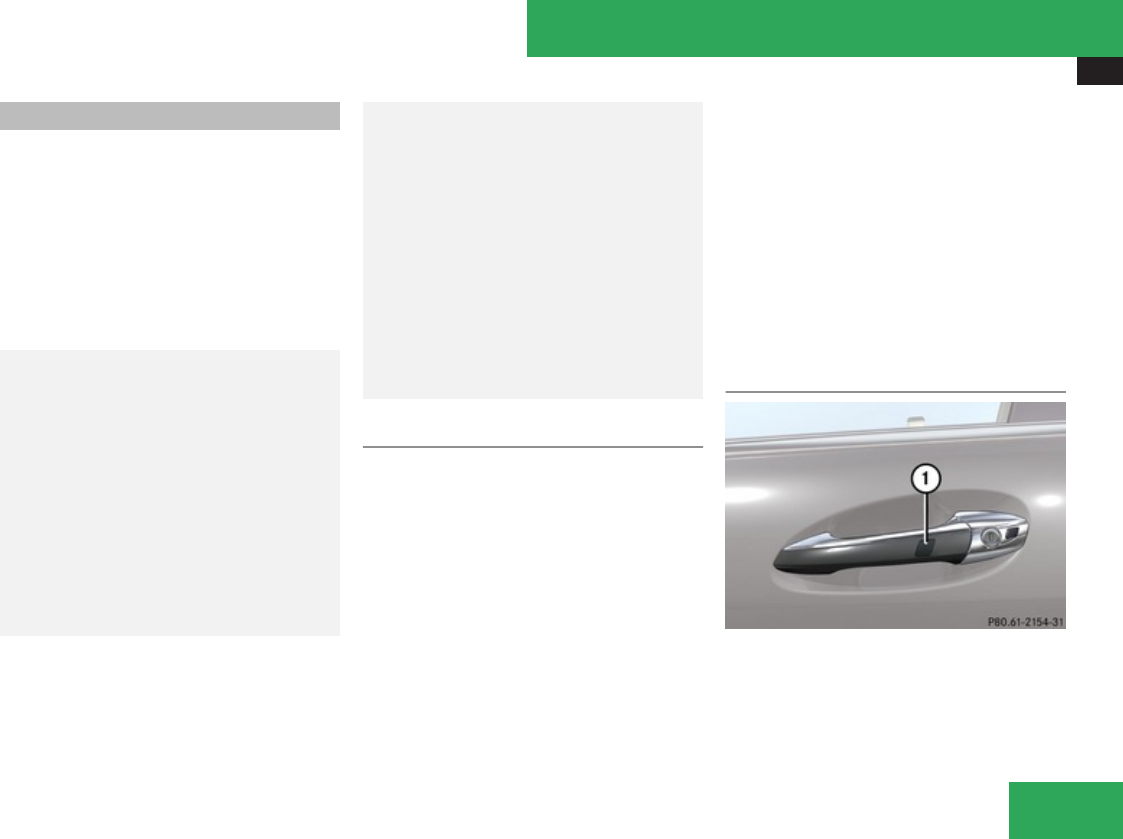
Power windows
337
Convenience closing feature
When locking the vehicle, you can
simultaneously close
Rthe door windows
Rthe tilt/sliding sunroof
Rthe panorama roof
Afterward, you can extend the roller
sunblinds of the panorama roof and the rear
door window sunshades.
GWarning!
When closing the door windows and the
tilt/sliding sunroof or panorama roof, make
sure there is no danger of anyone being
harmed by the closing procedure.
If potential danger exists, proceed as
follows:
RRelease button j to stop the closing
procedure. To open, press and hold
button k. To continue the closing
procedure after making sure that there is
no danger of anyone being harmed by the
closing procedure, press and hold button
j.
Vehicles with KEYLESS-GO:
RRelease the sensor surface on the
outside door handle to stop the closing
procedure.
RImmediately pull on the same outside
door handle and hold firmly. The door
windows and the tilt/sliding sunroof or
panorama roof will open for as long as the
door handle is held but the door not
opened.
With SmartKey
The SmartKey must be in close proximity to
the driver’s outside door handle.
XAim transmitter eye of the SmartKey at the
driver’s outside door handle.
XPress and hold button j on the
SmartKey until the door windows and the
tilt/sliding sunroof or panorama roof are
completely closed.
XRelease button j on the SmartKey to
interrupt the closing procedure.
XVehicles with panorama roof and/or
rear door window sunshades: Press
button j on the SmartKey once more.
The roller sunblinds and/or the rear door
window sunshades extend.
XPress button k on the SmartKey to
interrupt the extending procedure.
iVehicles with rear door window
sunshades: The rear window sunhade
extends simultaneously.
With KEYLESS-GO
1Sensor surface
The SmartKey with KEYLESS-GO must be
located outside the vehicle within
approximately 3 ft (1 m) of a door.
XClose all doors.
Controls in detail
Z

Driving and parking
338
XTouch and hold sensor surface 1 on an
outside door handle until the door windows
and the tilt/sliding sunroof or panorama
roof are completely closed.
iMake sure you are only touching the
sensor surface.
XRelease the sensor surface to interrupt the
closing procedure.
XVehicles with panorama roof and/or
rear door window sunshades: Touch and
hold the sensor surface once more.
The roller sunblinds and/or the rear door
window sunshades extend.
XPull on the outside door handle and hold
firmly to interrupt the extending procedure.
iVehicles with rear door window
sunshades: The rear window sunhade
extends simultaneously.
Driving and parking
Safety notes
GWarning!
Make sure absolutely no objects are
obstructing the pedals’ range of movement.
Keep the driver’s footwell clear of all
obstacles. If there are any floormats or
carpets in the footwell, make sure the
pedals still have sufficient clearance.
During sudden driving or braking
maneuvers the objects could get caught
between the pedals. You could then no
longer brake or accelerate. This could lead
to accidents and injury.
GWarning!
With the engine not running, there is no
power assistance for the brake and
steering systems. In this case, it is
important to keep in mind that a
considerably higher degree of effort is
necessary to brake and steer the vehicle.
Adapt your driving accordingly.
Starting the engine
GWarning!
Inhalation of exhaust gas is hazardous to
your health. All exhaust gas contains
carbon monoxide (CO), and inhaling it can
cause unconsciousness and possible
death.
Do not run the engine in confined areas
(such as a garage) which are not properly
ventilated. If you think that exhaust gas
fumes are entering the vehicle while
driving, have the cause determined and
corrected immediately. If you must drive
under these conditions, drive only with at
least one window fully open at all times.
Controls in detail
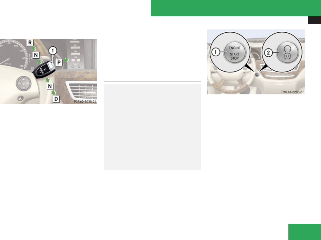
Driving and parking
339
Automatic transmission
Gearshift pattern for automatic transmission
1Button for selecting park position P
ÁPark position
ÂReverse gear
ÀNeutral position
¿Drive position
For more information on how to operate the
gear selector lever, see “Automatic
transmission” (Y page 345).
XMake sure the automatic transmission is in
park position P.
The transmission position indicator in the
multifunction display should be on P
(Y page 348).
With SmartKey
XDo not depress the accelerator pedal.
XTurn the SmartKey in the starter switch to
position 3 (Y page 307) and release it.
The engine starts automatically.
With KEYLESS-GO
GWarning!
As long as the SmartKey is in your vehicle,
the vehicle can be started. Therefore, never
leave children unattended in the vehicle, as
they could otherwise accidentally start the
engine.
When leaving the vehicle, always take the
SmartKey with you and lock the vehicle. Do
not leave children unattended in the
vehicle, or with access to an unlocked
vehicle. A child’s unsupervised access to a
vehicle could result in an accident and/or
serious personal injury.
You can start your vehicle without the
SmartKey in the starter switch using the
KEYLESS-GO start/stop button in the starter
switch.
The SmartKey must be located in the vehicle.
KEYLESS-GO start/stop button
1USA only
2Canada only
XMake sure the KEYLESS-GO start/stop
button is inserted in the starter switch.
iIf you wish to start the engine with the
SmartKey instead of the KEYLESS-GO
function, remove the KEYLESS-GO start/
stop button from the starter switch and
proceed as described in “With
SmartKey” (Y page 339).
XDepress the brake pedal during the starting
procedure.
XDo not depress the accelerator pedal.
Controls in detail
Z

Driving and parking
340
XPress the KEYLESS-GO start/stop button
once.
The engine starts automatically.
Starting difficulties
! Remember that extended starting
attempts can drain the battery.
The engine does not start. You can hear
the starter.
There could be a malfunction in the engine
electronics or in the fuel supply system.
Carry out the following steps:
XIf you are starting the engine with the
SmartKey: Turn the SmartKey in the starter
switch to position 0 and repeat the starting
procedure.
XIf you are starting the engine with KEYLESS-
GO: Close any doors that may be open to
allow for better detection of the SmartKey.
or
XRemove the KEYLESS-GO start/stop
button from the starter switch.
XStart the engine with the SmartKey as radio
signals from another source may be
interfering with the KEYLESS-GO function.
XRepeat the starting procedure.
If the engine does not start after several
starting attempts:
XContact an authorized Mercedes-Benz
Center or call Roadside Assistance.
The engine does not start. You cannot
hear the starter.
The battery may not be sufficiently charged.
XGet a jump start (Y page 578).
If the engine will not start despite a jump
start:
XContact an authorized Mercedes-Benz
Center or call Roadside Assistance.
The starter has been exposed to excessive
temperatures.
XLet the starter cool for about 2 minutes.
XRepeat the starting procedure.
If the engine does not start after several
starting attempts:
XContact an authorized Mercedes-Benz
Center or call Roadside Assistance.
Driving off
GWarning!
On slippery road surfaces, never downshift
in order to obtain braking action. This could
result in drive wheel slip and reduced
vehicle control. Your vehicle’s ABS will not
prevent this type of loss of control.
! Do not run cold engine at high engine
speeds. Running a cold engine at high
engine speeds may shorten the service life
of the engine. This is not covered by the
Mercedes-Benz Limited Warranty.
S 63 AMG: At engine temperatures below
68‡ (20†), the engine’s maximum speed
is restricted in order to protect it from
damage. Avoid driving your vehicle at full
speed when the engine is cold to prevent
premature engine wear and/or diminished
comfort.
Controls in detail

Driving and parking
341
! You have forgotten to release the
electronic parking brake when driving off if
Ran acoustic warning sounds
Rthe message Please Release Parking
Brake appears in the multifunction
display
Rthe red indicator lamp for the electronic
parking brake 0 (USA only) or !
(Canada only) in the instrument cluster
flashes
Release the electronic parking brake.
! Avoid spinning of a drive wheel. This may
cause serious damage to the drivetrain
which is not covered by the Mercedes-Benz
Limited Warranty.
! Simultaneously depressing the
accelerator pedal and applying the brakes
reduces engine performance and causes
premature brake and drivetrain wear which
is not covered by the Mercedes-Benz
Limited Warranty.
iOnce the vehicle is in motion, the
automatic central locking system engages
and the locking knobs in the doors move
down.
The automatic door lock feature can be
deactivated (Y page 222).
Automatic transmission
GWarning!
It is dangerous to shift the automatic
transmission out of park position P or
neutral position N if the engine speed is
higher than idle speed. If your foot is not
firmly on the brake pedal, the vehicle could
accelerate quickly forward or in reverse.
You could lose control of the vehicle and hit
someone or something. Only shift into gear
when the engine is idling normally and
when your right foot is firmly on the brake
pedal.
! Only shift the automatic transmission into
reverse gear R or park position P when the
vehicle is stopped. Otherwise the
automatic transmission could be damaged.
XDepress the brake pedal.
The gear selector lever can now be used.
XShift the automatic transmission into drive
position D or reverse gear R.
iShifting the automatic transmission out of
park position P is only possible with the
brake pedal depressed.
Without the brake pedal depressed, the
gear selector lever can be moved up or
down, but the parking pawl remains
engaged, not allowing shifting to occur.
XWait for the gear selection process to
complete before setting the vehicle in
motion.
XRelease the brake pedal.
XCarefully depress the accelerator pedal.
The electronic parking brake releases
automatically.
The red indicator lamp 0 (USA only)
or ! (Canada only) in the instrument
cluster goes out.
After a cold start, the automatic transmission
shifts at a higher engine revolution. This
allows the catalytic converter to reach its
operating temperature earlier.
For more information on driving, see “Driving
instructions” (Y page 475).
Controls in detail
Z

Driving and parking
342
Problems while driving
The engine runs erratically and misfires
RAn ignition cable may be damaged.
RThe engine electronics may not be
operating properly.
RUnburned gasoline may have entered the
catalytic converter and damaged it.
XGive very little gas.
XHave the problem checked at an authorized
Mercedes-Benz Center as soon as possible.
The coolant temperature is above
248‡ (120†)
The coolant is too hot and is no longer cooling
the engine.
XStop the vehicle in a safe location as soon
as possible.
XTurn off the engine immediately.
XAllow the engine and coolant to cool off.
XCheck the coolant level and add coolant if
necessary (Y page 448).
In case of accident
If the vehicle is leaking fuel:
XDo not start the engine under any
circumstances.
XExit the vehicle at a safe distance from the
roadway.
XNotify local fire and/or police authorities.
If the extent of the damage cannot be
determined:
XContact an authorized Mercedes-Benz
Center or call Roadside Assistance.
If no damage on major assemblies, fuel
system, and engine mount can be
determined:
XStart the engine in the usual manner.
Parking
GWarning!
Do not park this vehicle in areas where
combustible materials such as grass, hay
or leaves can come into contact with the
hot exhaust system, as these materials
could be ignited and cause a vehicle fire.
To reduce the risk of serious personal
injury, or damage to the vehicle or the
vehicle drivetrain, as a result of vehicle
movement, always do the following before
turning off the engine and leaving the
vehicle:
RKeep right foot on the brake pedal.
REngage the electronic parking brake.
RShift the automatic transmission into
park position P.
RSlowly release the brake pedal.
RWhen parked on an incline, always turn
the front wheels towards the road curb.
RTurn the SmartKey in the starter switch
to position 0 and remove the SmartKey
Controls in detail
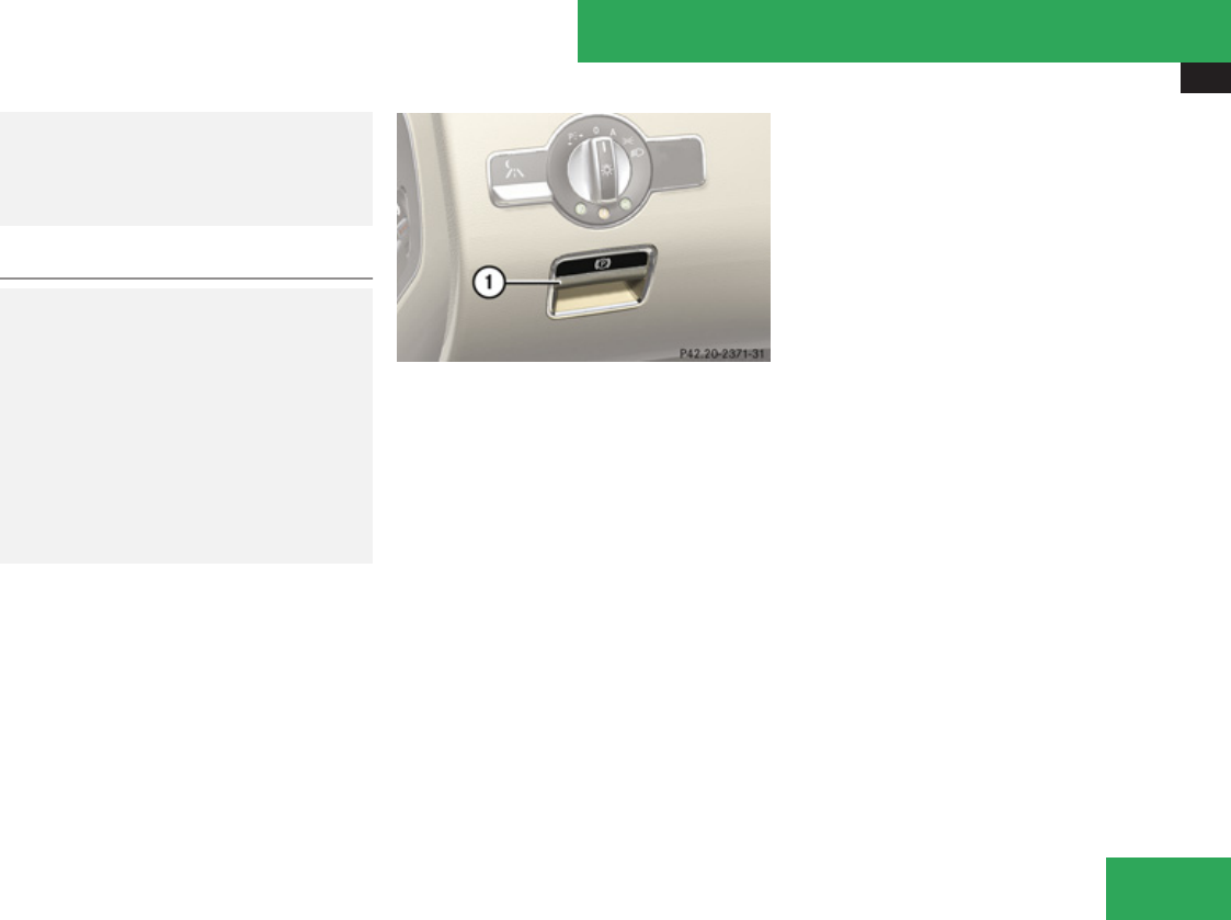
Driving and parking
343
from the starter switch, or press the
KEYLESS-GO start/stop button.
RTake the SmartKey with you and lock the
vehicle when leaving.
Electronic parking brake
GWarning!
When leaving the vehicle, always remove
the SmartKey from the starter switch, take
it with you, and lock the vehicle. Do not
leave children unattended in the vehicle, or
with access to an unlocked vehicle.
Children could release the electronic
parking brake and/or shift the automatic
transmission out of park position P, either
of which could result in an accident and/or
serious personal injury.
1Handle for electronic parking brake
Releasing electronic parking brake
manually
XMake sure the ignition is switched on.
XPull handle 1.
The red indicator lamp 0 (USA only)
or ! (Canada only) in the instrument
cluster goes out.
Releasing electronic parking brake
automatically
Your vehicle’s electronic parking brake
releases automatically when:
RThe engine is running.
RThe automatic transmission is in drive
position D or reverse gear R. With the
automatic transmission in reverse gear R
the trunk lid must be closed.
RThe hood is closed.
RYou have fastened your seat belt.
RYou press on the accelerator pedal.
iIf you have not fastened your seat belt,
the following conditions must be met in
order for the electronic parking brake to
release automatically:
RThe driver’s door is closed and you shift
the automatic transmission out of park
position P.
or
RThe driver’s door is closed and you drive
faster than 2 mph (3 km/h).
Engaging electronic parking brake
manually
XPress handle 1.
The red indicator lamp 0 (USA only)
or ! (Canada only) in the instrument
cluster comes on.
iYou can also engage the electronic
parking brake when the SmartKey is
removed from the starter switch.
Controls in detail
Z

Driving and parking
344
Engaging electronic parking brake
automatically
Your vehicle’s electronic parking brake
engages automatically when DISTRONIC Plus
(Y page 360) brings your vehicle to a
standstill, and at least one of the following
conditions is met:
RThe engine is turned off.
RThe driver’s door is opened and the seat
belt is not inserted in the seat belt buckle.
RThe hood lock is released.
RThe trunk lid is opened while the automatic
transmission is in reverse gear R.
RThe vehicle is stationary for an extended
period of time.
The red indicator lamp 0 (USA only)
or ! (Canada only) in the instrument
cluster comes on.
iIn addition to engaging the electronic
parking brake, the automatic transmission
will shift into park position P automatically.
Emergency braking with electronic
parking brake
In an emergency situation, you can also brake
your vehicle while driving by using the
electronic parking brake.
XWhile driving, press the handle for the
electronic parking brake (Y page 343).
iYour vehicle will be braked for as long as
you press and hold the handle for the
electronic parking brake. The longer you
keep the handle for the electronic parking
brake pressed, the more strongly your
vehicle will be braked. This method occurs
on all four wheels, not just the rear wheels.
During the braking procedure
Ran acoustic warning sounds
Rthe message Please Release Parking
Brake appears in the multifunction display
Rthe red indicator lamp for the electronic
parking brake 0 (USA only) or !
(Canada only) in the instrument cluster
flashes
Once the vehicle comes to a complete stop,
the electronic parking brake will engage
automatically.
Turning off the engine
GWarning!
Do not turn off the engine before the vehicle
has come to a complete stop. With the
engine not running, there is no power
assistance for the brake and steering
systems. In this case, it is important to keep
in mind that a considerably higher degree
of effort is necessary to brake and steer the
vehicle.
iIf the engine cannot be turned off as
described, see “Emergency engine
shutdown” (Y page 586).
XShift the automatic transmission into park
position P.
iWhen parked on an incline, also turn the
front wheels towards the road curb.
iObserve instructions if you want the
automatic transmission to remain in
neutral position N, see “Remaining in
neutral position N” (Y page 347).
With SmartKey
XTurn the SmartKey in the starter switch to
position 0.
Controls in detail

Automatic transmission
345
XRemove the SmartKey from the starter
switch.
The immobilizer is activated.
If you turn off the engine using the SmartKey,
and remove the SmartKey from the starter
switch or open a front door, the automatic
transmission will shift into park position P
automatically.
GWarning!
Keep in mind that turning off the engine
alone only will shift the automatic
transmission into neutral position N
automatically.
Always shift the automatic transmission
into park position P before turning off the
engine.
Otherwise the vehicle could roll away which
could result in an accident and/or serious
personal injury.
With KEYLESS-GO
XPress the KEYLESS-GO start/stop button.
With the driver’s door closed, the starter
switch is now in position 1. With the driver’s
door opened, the starter switch is set to
position 0, same as the SmartKey removed
from the starter switch (Y page 307).
If you turn off the engine using the KEYLESS-
GO start/stop button and open a front door,
the automatic transmission will shift into park
position P automatically.
GWarning!
Keep in mind that turning off the engine
alone only will shift the automatic
transmission into neutral position N
automatically.
Always shift the automatic transmission
into park position P before turning off the
engine.
Otherwise the vehicle could roll away which
could result in an accident and/or serious
personal injury.
iIn an emergency you can turn off the
engine while driving by pressing and
holding the KEYLESS-GO start/stop button
for approximately 3 seconds.
If you have started the engine with the
KEYLESS-GO start/stop button and cannot
turn it off as described above:
XRemove the KEYLESS-GO start/stop
button from the starter switch.
XInsert the SmartKey into the starter switch.
The engine turns off. The starter switch is
in position 0 (Y page 307).
Automatic transmission
Introduction
For information on driving with an automatic
transmission, see “Driving and
parking” (Y page 338).
GWarning!
Make sure absolutely no objects are
obstructing the pedals’ range of movement.
Keep the driver’s footwell clear of all
obstacles. If there are any floormats or
carpets in the footwell, make sure the
pedals still have sufficient clearance.
During sudden driving or braking
maneuvers the objects could get caught
between the pedals. You could then no
longer brake or accelerate. This could lead
to accidents and injury.
! Allow engine to warm up under low load
use. Do not place full load on the engine
until the operating temperature has been
reached.
Avoid spinning of a drive wheel for an
extended period when driving off on
slippery road surfaces.
This may cause serious damage to the
engine and the drivetrain which is not
Controls in detail
Z
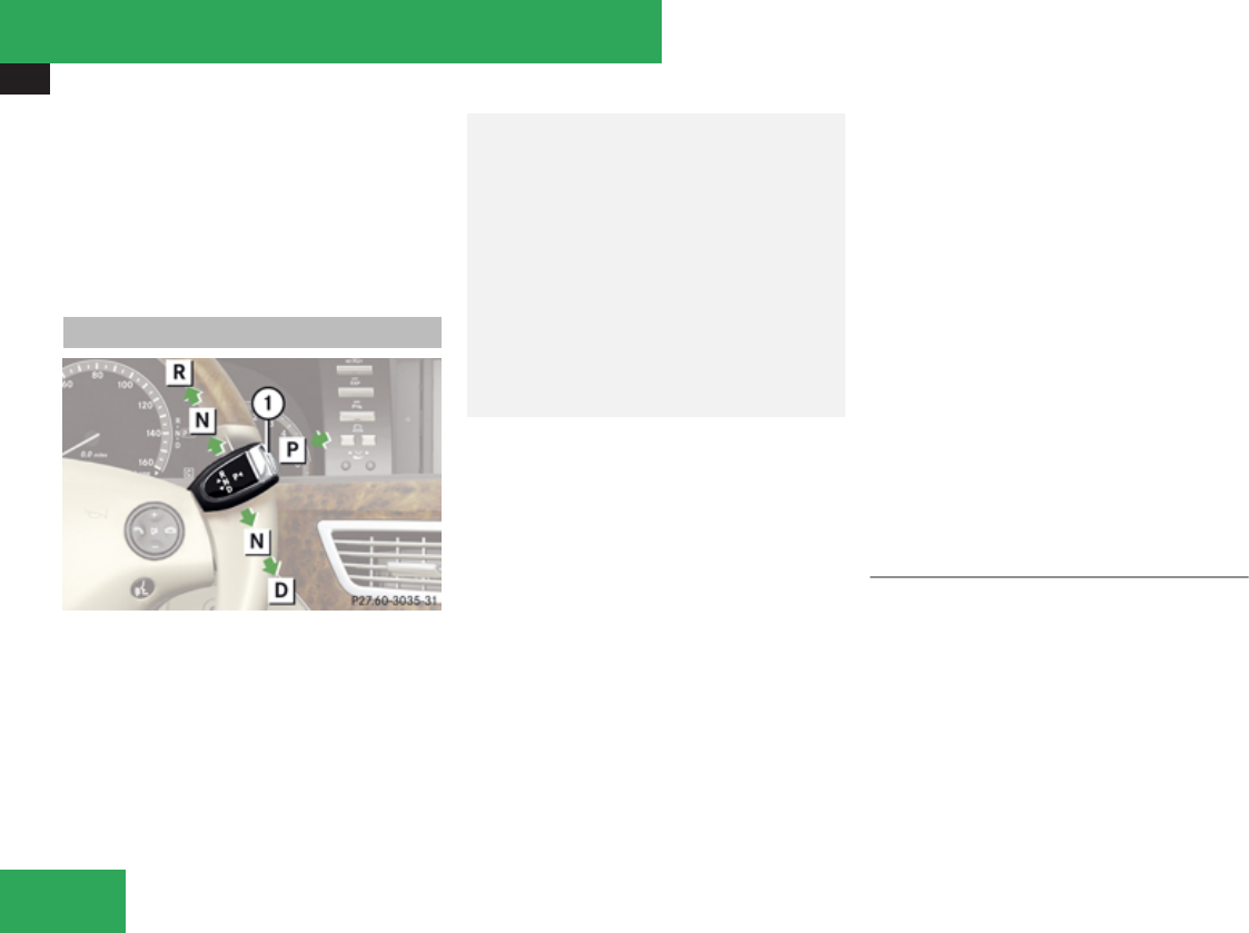
Automatic transmission
346
covered by the Mercedes-Benz Limited
Warranty.
iDuring the brief warm-up, transmission
upshifting is delayed. This allows the
catalytic converter to heat up more quickly
to operating temperature.
Gear selector lever
Gearshift pattern for automatic transmission
1Button for selecting park position P
ÁPark position
ÂReverse gear
ÀNeutral position
¿Drive position
GWarning!
It is dangerous to shift the automatic
transmission out of park position P or
neutral position N if the engine speed is
higher than idle speed. If your foot is not
firmly on the brake pedal, the vehicle could
accelerate quickly forward or in reverse.
You could lose control of the vehicle and hit
someone or something. Only shift into gear
when the engine is idling normally and
when your right foot is firmly on the brake
pedal.
! Only shift the automatic transmission into
reverse gear R or park position P when the
vehicle is stopped. Otherwise the
automatic transmission could be damaged.
! The vehicle must be stopped when you
shift the automatic transmission
Rdirectly between drive position D and
reverse gear R
Rdirectly between reverse gear R and
drive position D
Rdirectly into park position P
Otherwise the automatic transmission
could be damaged.
When trying to free a vehicle stuck in mud or
snow, see “Rocking the
vehicle” (Y page 349).
iShifting the automatic transmission out of
park position P is only possible with the
brake pedal depressed.
Without the brake pedal depressed, the
gear selector lever can be moved up or
down, but the parking pawl remains
engaged, not allowing shifting to occur.
iThe gear selector lever always returns to
its original position.
The current transmission position P, R, N,
or D appears in the multifunction display
(Y page 348).
Shifting into park position P
XWith the vehicle at a standstill, press button
1 on the gear selector lever to select park
position P.
SmartKey: When you turn off the engine using
the SmartKey, and remove the SmartKey
from the starter switch or open a front door,
the automatic transmission will shift into park
position P automatically.
KEYLESS-GO: When you turn off the engine
using the KEYLESS-GO start/stop button and
Controls in detail

Automatic transmission
347
open a front door, the automatic transmission
will shift into park position P automatically.
GWarning!
Keep in mind that turning off the engine
alone only will shift the automatic
transmission into neutral position N
automatically.
Always shift the automatic transmission
into park position P before turning off the
engine.
Otherwise the vehicle could roll away which
could result in an accident and/or serious
personal injury.
iMoving the gear selector lever up or down
shifts the automatic transmission out of
park position P.
DISTRONIC Plus:
The automatic transmission will shift into
park position P automatically when
DISTRONIC Plus brings your vehicle to a
standstill, and at least one of the following
conditions is met:
RThe engine is turned off.
RThe driver’s door is opened and the seat
belt is not inserted in the seat belt buckle.
RThe hood lock is released.
RThe trunk lid is opened while the automatic
transmission is in reverse gear R.
RThe vehicle is stationary for an extended
period of time.
In addition to shifting into park position P, the
electronic parking brake will engage
automatically.
Shifting into neutral position N
XWith the vehicle at a standstill, depress the
brake pedal and move the gear selector
lever up or down to the resistance point to
select neutral position N.
When you turn off the engine, the automatic
transmission will shift into neutral position
N automatically.
SmartKey: Removing the SmartKey from the
starter switch or opening a front door after
turning off the engine will shift the automatic
transmission into park position P
automatically.
KEYLESS-GO: Opening a front door after
turning off the engine will shift the automatic
transmission into park position P
automatically.
Remaining in neutral position N
If you want the automatic transmission to
remain in neutral position N, e.g. when taking
the vehicle through an automatic conveyor-
type car wash, observe the following
instructions:
GWarning!
When leaving the SmartKey in the starter
switch, do not leave children unattended in
the vehicle. It is possible for children to
switch on the ignition which could result in
unsupervised use of vehicle equipment.
Unsupervised use of vehicle equipment
could result in an accident and/or serious
personal injury.
With SmartKey:
XMake sure the ignition is switched on.
XWith the vehicle at a standstill, depress the
brake pedal and keep it pressed.
XShift the automatic transmission into
neutral position N.
XRelease the brake pedal.
XIf engaged, manually release the electronic
parking brake.
XSwitch off the ignition and leave the
SmartKey in the starter switch.
Controls in detail
Z
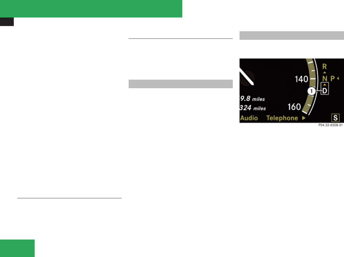
Automatic transmission
348
With KEYLESS-GO:
XMake sure the ignition is switched on.
XWith the vehicle at a standstill, depress the
brake pedal and keep it pressed.
XShift the automatic transmission into park
position P.
XRelease the brake pedal.
XRemove the KEYLESS-GO start/stop
button from the starter switch.
XInsert the SmartKey into the starter switch.
XSwitch on the ignition.
XDepress the brake pedal and keep it
pressed.
XShift the automatic transmission into
neutral position N.
XRelease the brake pedal.
XIf engaged, manually release the electronic
parking brake.
XSwitch off the ignition and leave the
SmartKey in the starter switch.
Shifting into reverse gear R
XWith the vehicle at a standstill, depress the
brake pedal and move the gear selector
lever up past the resistance point to select
reverse gear R.
Shifting into drive position D
XWith the vehicle at a standstill, depress the
brake pedal and move the gear selector
lever down past the resistance point to
select drive position D.
Shifting procedure
The automatic transmission selects individual
gears automatically, depending on:
Rthe selected gear range (Y page 350)
Rthe selected program mode:
C/S (Y page 350)
or
M (AMG vehicles only) (Y page 352)
Rthe position of the accelerator pedal
Rthe vehicle speed
With drive position D selected, you can
influence transmission shifting by:
Rlimiting the gear range
Rextending the gear range
Rchanging the gears manually (AMG vehicles
only)
Transmission positions
The current transmission position appears in
the multifunction display.
1Transmission position indicator
If the current transmission position does not
appear in the multifunction display due to a
malfunction, for example, make sure that the
automatic transmission is in the desired
position:
XShift the automatic transmission into drive
position D.
XSelect automatic program mode S.
XDo not limit the gear range.
XDrive off carefully.
Controls in detail

Automatic transmission
349
Effect
ìPark position
Shift the automatic transmission
into park position P only when the
vehicle is stopped. The park
position is not intended to serve
as a brake when the vehicle is
parked. Rather, the driver should
always engage the electronic
parking brake in addition to
shifting the automatic
transmission into park position P
to secure the vehicle.
If the vehicle’s electrical system is
malfunctioning, the automatic
transmission could remain locked
in park position P.
XHave the vehicle’s electrical
system checked at an
authorized Mercedes-Benz
Center as soon as possible.
íReverse gear
Shift the automatic transmission
into reverse gear R only when the
vehicle is stopped.
Effect
ëNeutral position
No power is transmitted from the
engine to the drive axle. When the
brakes are released, the vehicle
can be moved freely (pushed or
towed).
To avoid damage to the
transmission, never shift the
automatic transmission into
neutral position N while driving.
Exception: If the ESP® is
deactivated or malfunctioning,
shift the automatic transmission
into neutral position N if the
vehicle is in danger of skidding.
! Coasting the vehicle, or
driving for any other reason with
the automatic transmission in
neutral position N can result in
transmission damage that is not
covered by the Mercedes-Benz
Limited Warranty.
êDrive position
Effect
The automatic transmission shifts
automatically. All forward gears
are available.
Driving tips
Kickdown
Use the kickdown when you want maximum
acceleration.
XFully depress the accelerator pedal.
Depending on the engine speed the
automatic transmission shifts into a lower
gear.
Canada vehicles and AMG vehicles only:
XDepress the accelerator pedal past the
point of resistance to use the kickdown.
Rocking the vehicle
Rocking the vehicle by shifting the automatic
transmission directly between drive position
D and reverse gear R can help free a vehicle
stuck in mud or snow. The engine control
system of this vehicle electronically limits
directly shifting the automatic transmission
between drive position D and reverse gear R
to very low speeds, i.e. approximately 5 mph
Controls in detail
Z
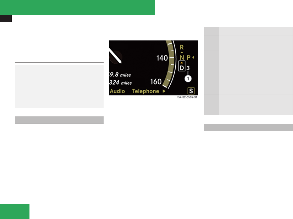
Automatic transmission
350
(9 km/h). To shift the automatic transmission
directly between drive position D and reverse
gear R, move the gear selector lever past the
resistance point up or down.
Working on the vehicle
GWarning!
When working on the vehicle, engage the
electronic parking brake and shift the
automatic transmission into park position
P. Otherwise the vehicle could roll away
which could result in an accident and/or
serious personal injury.
Gear ranges
With the automatic transmission in drive
position D and driving in automatic program
mode C or S, you can limit or extend the gear
range, see “One-touch
gearshifting” (Y page 351).
The current gear range appears in the
multifunction display.
1Gear range indicator
Effect
èWith this selection you can use the
braking effect of the engine.
çAllows the use of engine’s braking
power when driving
Ron steep downgrades
Rin mountainous regions
Runder extreme operating
conditions
æFor maximum use of engine’s
braking effect on very steep or
lengthy downgrades.
Automatic shift program
The program mode selector switch is used to
adjust
Rthe shift program
Rthe suspension tuning of the AIRMATIC or
the ABC system
Rthe engine control
Controls in detail
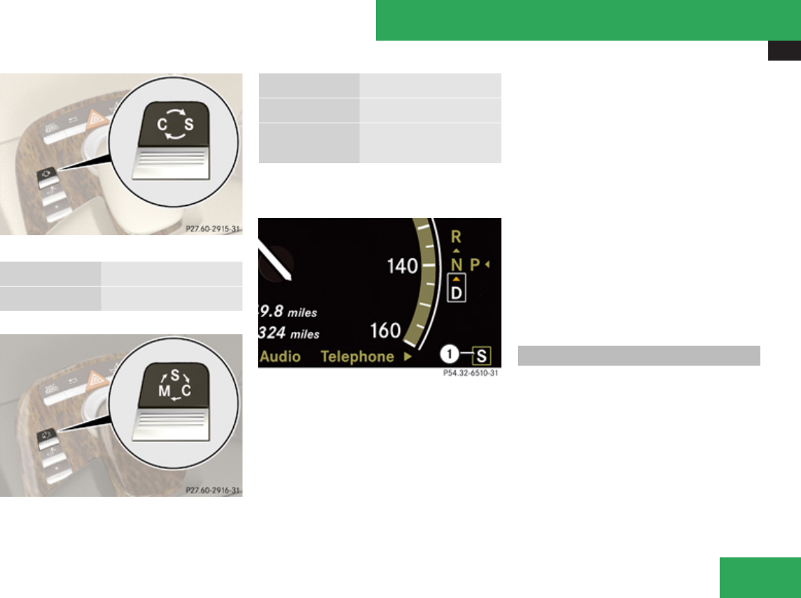
Automatic transmission
351
Program mode selector switch
C Comfort For comfort driving
S Sport For standard driving
Program mode selector switch on AMG vehicles
C Comfort For standard driving
S Sport For sporty driving
M Manual For manual gearshifting
(Y page 352)
The current program mode appears in the
multifunction display.
1Program mode indicator
You should only change the program mode
when the automatic transmission is in park
position P.
iThe last selected automatic program
mode (C or S) is switched on when the
engine is restarted.
XPress the program mode selector switch
repeatedly until the letter of the desired
program mode appears in the multifunction
display.
Selecting program mode C means:
RThe vehicle starts out more gentle, both
forward and reverse, except when driving
off with full throttle.
RTraction and driving stability are improved
on icy roads.
RUpshifts occur earlier even when you give
more gas. The engine then operates at
lower revolutions and the wheels are less
likely to spin.
Selecting program mode S means that
upshifts occur later.
One-touch gearshifting
With the automatic transmission in drive
position D and driving in automatic program
mode C or S, you can limit or extend the gear
range using the steering wheel gearshift
contol.
AMG vehicles: For information on using the
steering wheel gearshift control in manual
program mode M, see “Manual shift
program” (Y page 352).
Controls in detail
Z
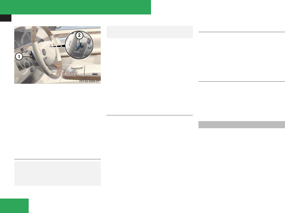
Automatic transmission
352
Steering wheel gearshift control (example
illustration)
1Limiting gear range
Downshift (in manual program mode M)
2Extending gear range
Upshift (in manual program mode M)
iYou cannot shift with the steering wheel
gearshift control when the automatic
transmission is in park position P, neutral
position N, or reverse gear R.
Limiting gear range
GWarning!
On slippery road surfaces, never downshift
in order to obtain braking action. This could
result in drive wheel slip and reduced
vehicle control. Your vehicle’s ABS will not
prevent this type of loss of control.
XBriefly pull left gearshift control 1.
The automatic transmission will shift into
the next lower gear as permitted by the
shift program. This action simultaneously
limits the gear range of the automatic
transmission.
iTo avoid overrevving the engine when
downshifting, the automatic transmission
will not shift into a lower gear if the engine’s
maximum speed would be exceeded.
Extending gear range
XBriefly pull right gearshift control 2.
The automatic transmission will shift into
the next higher gear as permitted by the
shift program. This action simultaneously
extends the gear range of the automatic
transmission.
iIf you press on the accelerator pedal
when the engine has reached the
revolution limit of the current gear range,
the automatic transmission will upshift
beyond any gear range limit selected.
Canceling gear range limit
XPull and hold right gearshift control 2 until
the gear range indicator disappears from
the multifunction display.
The automatic transmission will shift from
the current gear range directly into drive
position D.
Shifting into optimal gear range
XPull and hold left gearshift control 1.
The automatic transmission will select the
gear range suited for optimal acceleration
and deceleration automatically. This will
involve shifting down one or more gears.
Manual shift program
The manual shift program is available on AMG
vehicles only.
Manual program mode M differs with regard
to spontaneity, response time, and shifting
smoothness from automatic program mode
S.
In manual program mode M, system-
controlled automatic gearshifting is switched
off. You need to change the gears by manually
upshifting or downshifting using the steering
wheel gearshift control.
Controls in detail
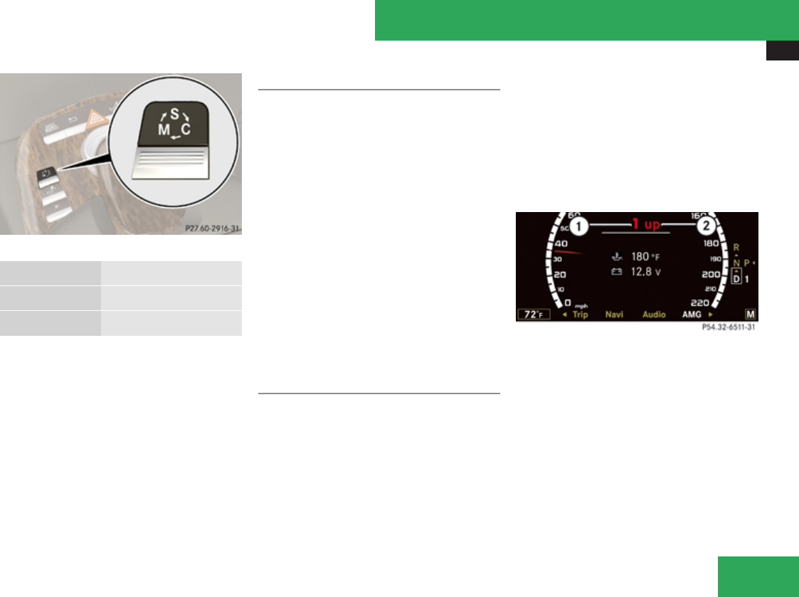
Automatic transmission
353
Program mode selector switch
C Comfort For standard driving
S Sport For sporty driving
M Manual For manual gearshifting
The current program mode appears in the
multifunction display (Y page 351).
For information on automatic program mode
(C or S), see “Automatic shift
program” (Y page 350) and “One-touch
gearshifting” (Y page 351).
Activating manual shift program
XPress the program mode selector switch
repeatedly until M appears in the
multifunction display.
The automatic transmission switches to
manual program mode M. Automatic
shifting is switched off. The gear range is
not limited.
You can change the gears manually with drive
position D selected. You can upshift or
downshift through the gears in succession.
iManual program mode M will not be
stored. When the engine is turned off with
manual program mode M selected, the
automatic transmission will go to
automatic program mode (C or S) when the
engine is restarted.
Upshifting
! In manual program mode M, the
automatic transmission will not upshift,
even if the engine has reached its
overrevving range. Shift up into the next
gear before the engine has reached its
overrevving range. Make absolutely certain
that the engine speed does not reach the
red marking on the tachometer. Otherwise
the engine could be damaged which is not
covered by the Mercedes-Benz Limited
Warranty.
XBriefly pull right gearshift control 2
(Y page 352).
The automatic transmission shifts into the
next higher gear.
Upshift indicator
1Current gear
2Upshift indicator
In manual program mode M, upshift indicator
2 in the multifunction display advises you to
upshift before the engine reaches the
overspeed range. Thus you can drive at the
maximum engine speed for each gear without
overrevving the engine.
Controls in detail
Z

Automatic transmission
354
XShift the automatic transmission from
current gear 1 into the next higher gear.
The fuel supply will otherwise be
interrupted to prevent the engine from
overrevving.
Downshifting
GWarning!
On slippery road surfaces, never downshift
in order to obtain braking action. This could
result in drive wheel slip and reduced
vehicle control. Your vehicle’s ABS will not
prevent this type of loss of control.
XBriefly pull left gearshift control 1
(Y page 352).
The automatic transmission shifts into the
next lower gear.
iFor maximum acceleration, pull and hold
the left gearshift control. Depending on the
engine speed the automatic transmission
selects the optimal gear for maximum
acceleration.
iWhen you brake or stop, the automatic
transmission shifts down into a gear from
which you can easily accelerate or take off.
Kickdown
Using the kickdown when driving in manual
program mode M is not possible.
Deactivating manual shift program
XPress the program mode selector switch
repeatedly until C or S appears in the
multifunction display.
or
XRestart the engine.
The automatic transmission will go to
automatic program mode (C or S).
Manual program mode M is not stored.
Emergency operation (limp-home
mode)
If vehicle acceleration becomes less
responsive or sluggish or the automatic
transmission no longer shifts, the automatic
transmission is most likely operating in limp-
home (emergency operation) mode. In this
mode only second gear and reverse gear R
can be selected.
XStop the vehicle in a safe location.
XShift the automatic transmission into park
position P.
XTurn off the engine.
XWait at least 10 seconds before restarting.
XRestart the engine.
XShift the automatic transmission into drive
position D (for second gear) or reverse gear
R.
XHave the automatic transmission checked
at an authorized Mercedes-Benz Center as
soon as possible.
Controls in detail
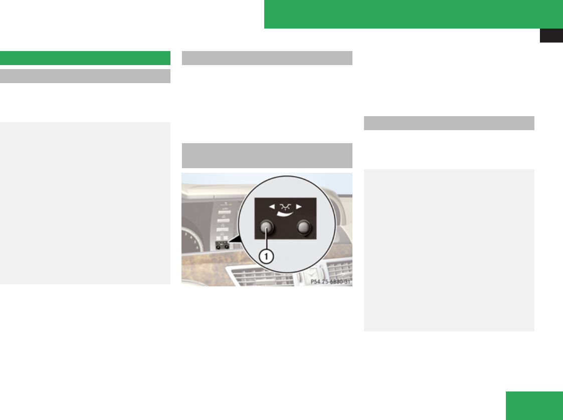
Instrument cluster
355
Instrument cluster
Introduction
For a full view illustration of the instrument
cluster, see “Instrument
cluster” (Y page 30).
GWarning!
No messages will be displayed if either the
instrument cluster or the multifunction
display is inoperative.
As a result, you will not be able to see
information about your driving conditions,
such as speed or outside temperature,
warning/indicator lamps, malfunction/
warning messages or the failure of any
systems. Driving characteristics may be
impaired.
If you must continue to drive, please do so
with added caution. Contact an authorized
Mercedes-Benz Center as soon as possible.
The language setting for the multifunction
display can be changed via COMAND
(Y page 98).
Activating the instrument cluster
The instrument cluster is activated when you
Ropen a door
Rswitch on the ignition
Rswitch on the exterior lamps
Adjusting the instrument cluster
illumination
1Knob
iThe instrument cluster illumination is
dimmed or brightened automatically to suit
ambient light conditions.
The instrument cluster illumination will also
be adjusted automatically when you switch
on the vehicle’s exterior lamps.
XTo brighten illumination: Turn knob 1
clockwise.
XTo dim illumination: Turn knob 1
counterclockwise.
Coolant temperature gauge
The coolant temperature gauge is located on
the left side in the instrument cluster
(Y page 30).
GWarning!
Driving when your engine is overheated can
cause some fluids which may have leaked
into the engine compartment to catch fire.
You could be seriously burned.
Steam from an overheated engine can
cause serious burns which can occur just
by opening the engine hood. Stay away
from the engine if you see or hear steam
coming from it.
Stop the vehicle in a safe location away
from other traffic. Turn off the engine, get
out of the vehicle and do not stand near the
vehicle until the engine has cooled down.
During severe operating conditions, e.g. stop-
and-go traffic, the coolant temperature may
rise close to 248‡ (120†), i.e close to the
red zone of the temperature gauge.
Controls in detail
Z

Driving systems
356
! Excessive coolant temperature triggers a
warning in the multifunction display.
The engine should not be operated with a
coolant temperature above 248‡ (120†),
i.e. in the red zone of the coolant
temperature gauge. Doing so may cause
serious engine damage which is not
covered by the Mercedes-Benz Limited
Warranty.
Tachometer
The red marking on the tachometer
(Y page 30) denotes excessive engine speed.
! Avoid driving at excessive engine speeds,
as it may result in serious engine damage
that is not covered by the Mercedes-Benz
Limited Warranty.
To help protect the engine, the fuel supply is
interrupted if the engine is operated within
the red marking.
Outside temperature indicator
The outside temperature indicator is on the
bottom left-hand side of the instrument
cluster (Y page 30).
GWarning!
The outside temperature indicator is not
designed to serve as an ice-warning device
and is therefore unsuitable for that
purpose.
Indicated temperatures just above the
freezing point do not guarantee that the
road surface is free of ice. The road may still
be icy, especially in wooded areas or on
bridges.
Fuel gauge
The fuel gauge is on the left-hand side of the
instrument cluster (Y page 30). Once the fuel
level has fallen below the reserve mark, the
yellow segment indicator for the fuel reserve
comes on.
Driving systems
Introduction
This section describes the following driving
systems of your vehicle:
RCruise control and DISTRONIC Plus
RHill start assist system
RAIRMATIC
RActive Body Control (ABC)
RAll-wheel drive (4MATIC)
RParktronic system
RPark Assist
RAdvanced Parking Guidance
RRear View Camera
RNight View Assist
RBlind Spot Assist
The ABS, Adaptive Brake, BAS, BAS Plus, EBP,
ESP® and PRE-SAFE® Brake driving safety
systems are described in the “Safety and
security” section (Y page 69).
Controls in detail
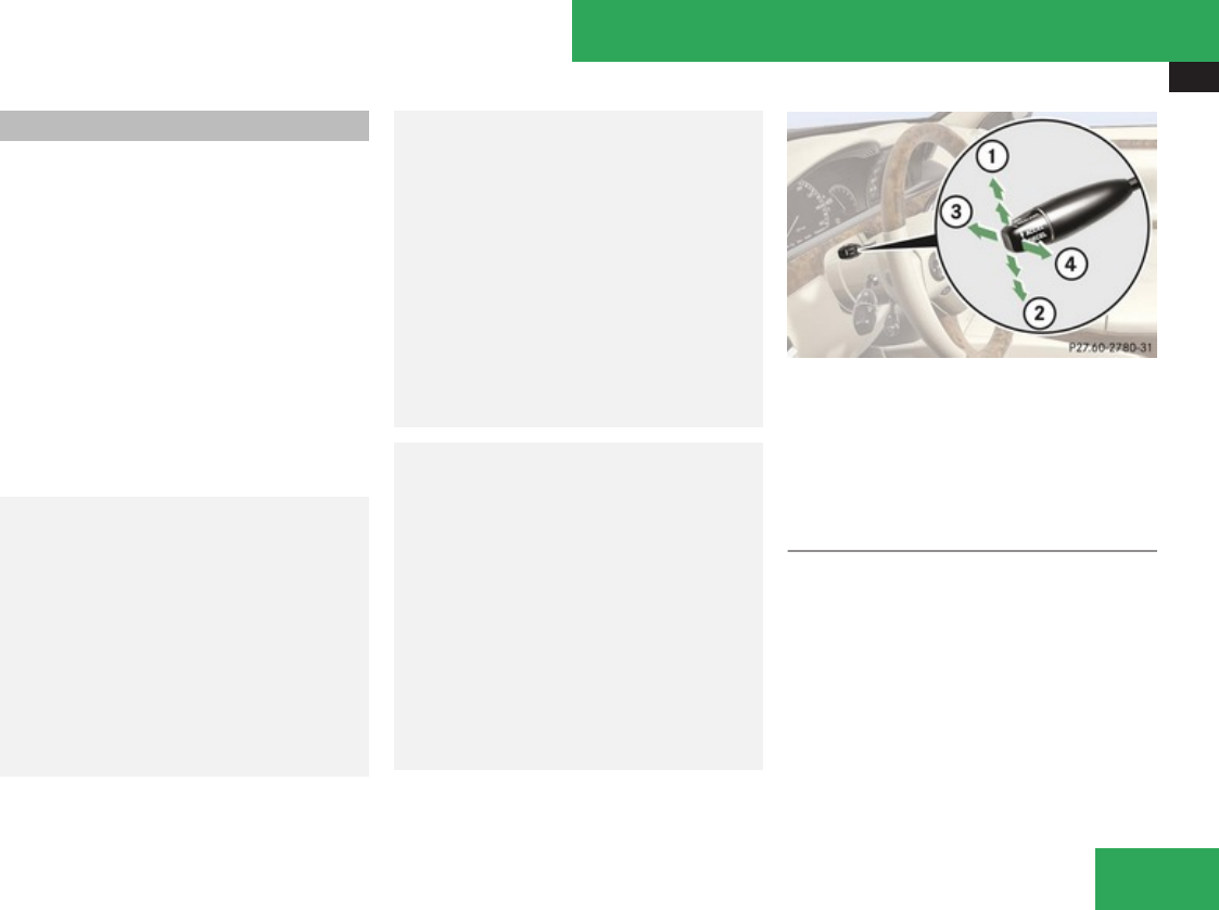
Driving systems
357
Cruise control
The cruise control automatically maintains
the speed you set for your vehicle.
The use of the cruise control is recommended
for driving at a constant speed for extended
periods of time.
The currently set speed or last set speed
(“Resume” function) appears in the
multifunction display for approximately
5 seconds. The set speed is shown by a
triangle in the speedometer and the
corresponding speedometer segments from
the selected speed to the vehicle maximum
speed in the multifunction display are
illuminated.
GWarning!
The cruise control is a convenience system
designed to assist the driver during vehicle
operation. The driver is and must always
remain responsible for the vehicle’s speed
and for safe brake operation.
Only use the cruise control if the road,
traffic, and weather conditions make it
advisable to travel at a constant speed.
RThe use of the cruise control can be
dangerous on winding roads or in heavy
traffic because conditions do not allow
safe driving at a constant speed.
RThe use of the cruise control can be
dangerous on slippery roads. Rapid
changes in tire traction can result in
wheel spin and loss of control.
RDeactivate the cruise control when
driving in fog.
The “Resume” function should only be
operated if the driver is fully aware of the
previously set speed and wishes to resume
this particular preset speed.
GWarning!
The cruise control brakes automatically so
that the set speed is not exceeded. The
brake pedal depresses automatically when
the cruise control engages the brakes.
Keep the driver’s footwell clear at all times,
including the area under the brake pedal.
Objects stored in this area may impair
pedal movement which could interfere with
the braking ability of the cruise control
system.
Do not place your foot under the brake
pedal – your foot could become caught.
1Setting current or higher speed
2Setting current or lower speed
3Canceling the cruise control
4Activating the cruise control or resuming
to last set speed
Activating cruise control
You can activate the cruise control at a
vehicle speed above 20 mph (30 km/h).
You cannot activate the cruise control:
Rwhen you brake
Rwhen you have engaged the electronic
parking brake
Controls in detail
Z

Driving systems
358
Rwhen the automatic transmission is in park
position P, reverse gear R, or neutral
position N
Rthe ESP® is switched off or has switched off
due to a malfunction
The vehicle speed displayed in the
speedometer can briefly vary from the speed
setting for the cruise control system.
Setting current speed
XAccelerate or decelerate to the desired
speed.
XBriefly lift the cruise control lever in
direction of arrow 1 or press in direction
of arrow 2.
XRemove your foot from the accelerator
pedal.
iOn uphill grades, the cruise control may
not be able to maintain the set speed. Once
the grade eases, the set speed will be
resumed.
On downhill grades, the cruise control
maintains the set speed by braking with the
vehicle’s brake system. In addition, on
longer downhill grades the automatic
transmission will downshift automatically.
Canceling cruise control
XDepress the brake pedal.
or
XBriefly push the cruise control lever in
direction of arrow 3.
The last set speed is stored for later use.
The last stored speed is deleted from memory
when the engine is turned off.
The cruise control switches off automatically
when you depress the brake pedal or you
engage the electronic parking brake. In this
case, the speedometer segments in the
multifunction display will go out.
The cruise control also switches off
automatically when
Rthe vehicle speed falls below 20 mph
(30 km/h)
Rthe ESP® is in operation
Rthe ESP® is switched off with the ESP®
switch
Rthe ESP® has switched off due to a
malfunction
Ryou shift the automatic transmission into
neutral position N while driving
The speedometer segments in the
multifunction display goes out and an
acoustic warning will sound. Observe
additional messages in the multifunction
display that may appear.
Depressing the accelerator pedal does not
deactivate the cruise control. After a brief
acceleration (e.g. for passing), the cruise
control will resume the last set speed.
Changing the set speed
GWarning!
Keep in mind that it may take a brief
moment until the vehicle has made the
necessary adjustments.
Increase or decrease the set vehicle speed
to a value that the prevailing road
conditions and legal speed limits permit.
Otherwise, sudden and unexpected
acceleration or deceleration of the vehicle
could cause an accident and/or serious
injury to you and others.
You can increase or decrease the set speed
in 1 mph (Canada: 1 km/h) increments or in
5 mph (Canada: 10 km/h) increments.
When you use the cruise control lever to
decelerate, the brake system will brake the
vehicle automatically if the engine’s braking
power does not brake the vehicle sufficiently.
Controls in detail

Driving systems
359
Adjustment in 1 mph (Canada: 1 km/h)
increments
iThe set speed value is increased or
decreased in 1 mph (Canada: 1 km/h)
increments each time you lift or press the
cruise control lever up or down to the
resistance point.
XBriefly lift the cruise control lever up to the
resistance point in direction of arrow 1 to
increase or press the cruise control lever
down to the resistance point in direction of
arrow 2 to decrease.
XRelease the cruise control lever.
The new speed is set and the vehicle will
accelerate or decelerate.
Adjustment in 5 mph (Canada: 10 km/h)
increments
iThe set speed value is increased or
decreased in 5 mph (Canada: 10 km/h)
increments each time you lift or press the
cruise control lever up or down past the
resistance point.
XBriefly lift the cruise control lever up past
the resistance point in direction of arrow
1 to increase or press the cruise control
lever down past the resistance point in
direction of arrow 2 to decrease.
XRelease the cruise control lever.
The new speed is set and the vehicle will
accelerate or decelerate. Keep in mind that
it may take a brief moment until the vehicle
has reached the set speed.
Resume last stored speed
GWarning!
The set speed stored in memory should
only be set again if prevailing road
conditions and legal speed limits permit.
Possible acceleration or deceleration
differences arising from returning to the
preset speed could cause an accident and/
or serious injury to you and others.
XBriefly pull the cruise control lever in
direction of arrow 4.
If no speed is stored, the current speed is
set and stored.
XRemove your foot from the accelerator
pedal.
The last stored speed is deleted from memory
when the engine is turned off.
Hill start assist system
GWarning!
The hill start assist system is not designed
to function as a parking brake and does not
prevent the vehicle from moving when
parked on an incline.
Always engage the electronic parking brake
in addition to shifting the automatic
transmission into park position P.
On uphill grades with a gradient angle of more
than 5°, the hill start assist system maintains
the pressure in the brake system for
approximately 1 second after you have
released the brake pedal. Therefore, you can
start off smoothly without the vehicle moving
immediately after releasing the brake pedal.
XDepress the brake pedal.
XShift the automatic transmission into drive
position D or reverse gear R.
XRelease the brake pedal.
XCarefully depress the accelerator pedal.
The hill start assist system is inactive
Rwhen starting off on a level road or downhill
grades
Rwith the automatic transmission in neutral
position N
Controls in detail
Z

Driving systems
360
Rwith the electronic parking brake engaged
Rif the ESP® has switched off due to a
malfunction
DISTRONIC Plus
Safety notes
When activated, the DISTRONIC Plus
adaptive cruise control system increases the
driving convenience afforded by the cruise
control while traveling on expressways and
other major roadways.
RIf the DISTRONIC Plus distance sensor
detects a slower moving vehicle directly
ahead, your vehicle speed will be reduced
so that you follow that vehicle at your
preset following distance.
RIf there is no vehicle directly ahead of you,
the DISTRONIC Plus will function in the
same way as standard cruise control
(Y page 357).
GWarning!
The DISTRONIC Plus requires familiarity
with its operational characteristics. We
strongly recommend that you review the
following information carefully before
operating the system.
GWarning!
The DISTRONIC Plus is a convenience
system. Its speed adjustment reduction
capability is intended to make cruise
control more effective and usable when
traffic speeds vary. It is not however,
intended to, nor does it, replace the need
for extreme care.
The responsibility for the vehicle’s speed,
distance to the preceding vehicle and, most
importantly, brake operation to ensure a
safe stopping distance, always remains
with the driver.
The DISTRONIC Plus cannot take street and
traffic conditions into account.
Complex driving situations are not always
fully recognized by the DISTRONIC Plus.
This could result in wrong or missing
distance warnings.
GWarning!
The DISTRONIC Plus adaptive cruise
control is not a substitute for active driving
involvement. It does not react to
pedestrians or on stationary objects, nor
does it recognize or predict the curvature
and lane layout or the movement of
preceding vehicles. The DISTRONIC Plus
can only apply a maximum of 40% of the
vehicle’s braking power.
The DISTRONIC Plus may not detect narrow
vehicles possibly driving in front of you,
such as motorcycles and vehicles driving in
an offset formation.
It is the driver’s responsibility at all times to
be attentive to the road, weather and traffic
conditions. Additionally, the driver must
provide the steering, braking and other
driving inputs necessary to remain in
control of the vehicle.
High-frequency sources such as toll
stations, speed measuring systems etc.
can cause the DISTRONIC Plus system to
temporarily cease functioning.
GWarning!
The DISTRONIC Plus cannot take road and
traffic conditions into account. Only use the
DISTRONIC Plus if the road, weather and
traffic conditions make it advisable to travel
at a constant speed.
GWarning!
Use of the DISTRONIC Plus can be
dangerous on slippery roads. Rapid
Controls in detail

Driving systems
361
changes in tire traction can result in wheel
spin and loss of control.
The DISTRONIC Plus does not function in
adverse sight and distance conditions. Do
not use the DISTRONIC Plus during
conditions of fog, heavy rain, snow or sleet.
GWarning!
The DISTRONIC Plus cannot take weather
conditions into account. Switch off the
DISTRONIC Plus or do not switch it on if:
Rroads are slippery or covered with snow
or ice. The wheels could lose traction
while braking or accelerating, and the
vehicle could skid.
Rthe DISTRONIC Plus system sensor cover
is dirty or visibility is diminished due to
snow, rain or fog, for example. The
distance control system functionality
could be impaired.
Always pay attention to surrounding traffic
conditions even while the DISTRONIC Plus
is switched on. Otherwise, you may not be
able to recognize dangerous situations until
it is too late. This could cause an accident
in which you and/or others could be
injured.
GWarning!
The “Resume” function should only be
operated if the driver is fully aware of the
previously set speed and wishes to resume
this particular preset speed.
GWarning!
Close attention to road and traffic
conditions is imperative at all times,
regardless of whether or not the
DISTRONIC Plus is activated.
Use of the DISTRONIC Plus can be
dangerous on winding roads or in heavy
traffic because conditions do not allow safe
driving at a constant speed.
The DISTRONIC Plus will not react to
stationary objects in the roadway (e.g. a
stopped vehicle in a traffic jam or a disabled
vehicle). The DISTRONIC Plus will also not
respond to oncoming vehicles.
Switch off the DISTRONIC Plus:
Rwhen changing from the left to the right
lane if vehicles are moving more slowly
in the left lane
Rwhen entering a turn lane or highway off
ramp
Rin complex driving situations, such as in
highway construction zones
In these situations, the DISTRONIC Plus will
continue to maintain the set speed unless
deactivated.
The DISTRONIC Plus is designed and
intended only to maintain a set speed and
keep a set distance from moving objects in
front of it.
The DISTRONIC Plus functions in a speed
range of 0 to 120 mph
(Canada: 0 to 200 km/h).
Do not use the DISTRONIC Plus if you are
driving on a road with steep uphill or downhill
slopes.
When traveling in Canada in a vehicle not
registered in Canada, you must switch off the
radar sensor system (Y page 253). Canadian
law does not permit the use of the radar
sensor system for vehicles from outside of
Canada. When you switch off the radar sensor
Controls in detail
Z
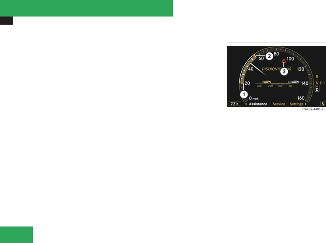
Driving systems
362
system, the following functions are
deactivated:
RDISTRONIC Plus
RBAS Plus (Y page 70)
RPRE-SAFE® Brake(Y page 76)
RPark Assist (Y page 379)
RAdvanced Parking Guidance (Y page 383)
RBlind Spot Assist (Y page 392)
iDue to its radar-emitting nature
DISTRONIC Plus may have an appearance
similar to a radar detector to law
enforcement officials. You may want to
refer to this section of your Operator’s
Manual when asked.
iUSA only:
This device has been approved by the FCC
as a “Vehicular Radar System”. The radar
sensor is intended for use in an automotive
radar system only. Removal, tampering, or
altering of the device will void any
warranties, and is not permitted by the
FCC. Do not tamper with, alter, or use in
any non-approved way.
Any unauthorized modification to this
device could void the user’s authority to
operate the equipment.
iCanada only:
This device complies with RSS-210 of
Industry Canada. Operation is subject to
the following two conditions:
1. This device may not cause interference,
and
2. this device must accept any
interference received, including
interference that may cause undesired
operation of the device.
Removal, tampering, or altering of the
device will void any warranties, and is not
permitted. Do not tamper with, alter, or use
in any non-approved way.
Any unauthorized modification to this
device could void the user’s authority to
operate the equipment.
DISTRONIC Plus displays in
multifunction display
1Speed of the vehicle ahead
2Set speed
3Distance warning lamp
If the DISTRONIC Plus is activated, the marker
2 indicates the set speed.
The vehicle speed displayed on the
speedometer can briefly vary from the speed
setting on the DISTRONIC Plus system.
If the DISTRONIC Plus detects a vehicle
directly ahead, the ring on the speedometer
dial comes on between the speed of the
vehicle ahead 1 and the set speed 2.
If the DISTRONIC Plus calculates that there is
a danger of collision, the distance warning
Controls in detail

Driving systems
363
lamp l in the instrument cluster comes
on and an intermittent warning sounds.
XImmediately apply the brake to avoid a
collision.
Under no circumstances should the driver
await the intermittent warning sound
before braking. See the following warning
note.
The intermittent warning sound ceases and
the distance warning lamp l goes out
when the necessary distance to the vehicle
ahead is again established.
GWarning!
An intermittent warning sounds and the
distance warning lamp l in the
instrument cluster is illuminated if the
DISTRONIC Plus system calculates that the
distance to the vehicle ahead and your
vehicle’s current speed indicate that the
DISTRONIC Plus will not be capable of
slowing the vehicle sufficiently to maintain
the preset following distance, which
creates a danger of a collision.
Immediately brake the vehicle to increase
your distance to the preceding vehicle. The
warning sound is intended as a final caution
in which you should intercede with your
own braking inputs to avoid a potentially
dangerous situation. Do not wait for the
operation of the warning signal to intercede
with your own braking. This will result in
potentially dangerous emergency braking
which will not always result in an impact
being avoided.
Tailgating increases the risk of an accident.
GWarning!
The DISTRONIC Plus brakes your vehicle
with a maximum deceleration of 13 ft/s2
(4 m/s2). This corresponds to
approximately 40% of the maximum
deceleration of your vehicle.
You must also apply the brakes yourself to
avoid a collision. The DISTRONIC Plus
brakes the vehicle in an effort to restore the
preset distance or to maintain the set
speed. The brake pedal is automatically
applied as this happens which results in the
brake pedal moving
Keep driver’s foot area clear at all times,
including the area under the brake pedal.
Objects stored in this area may impair
pedal movement which could interfere with
the braking ability of the DISTRONIC Plus
system.
Do not place your foot under the brake
pedal – your foot could become caught.
GWarning!
If you do not receive visual or acoustic
warning signals during a critical traffic
situation, DISTRONIC Plus has either not
recognized the collision risk, has been
deactivated or is malfunctioning.
Remember, whether or not DISTRONIC
Plus is operating, it is ultimately always the
drivers responsibility to apply the brakes in
order to control the vehicle and avoid a
collision.
Displaying the distance graphic
In the Assistance menu under Distance
Display you see the current settings for
DISTRONIC Plus. The Information shown in
the multifunction display depends on whether
DISTRONIC Plus is activated or deactivated.
For activating or deactivating the DISTRONIC
Plus system, see “Activating DISTRONIC
Plus” (Y page 365) or “Deactivating
DISTRONIC Plus” (Y page 369).
The menu overview can be found on
(Y page 240).
Controls in detail
Z
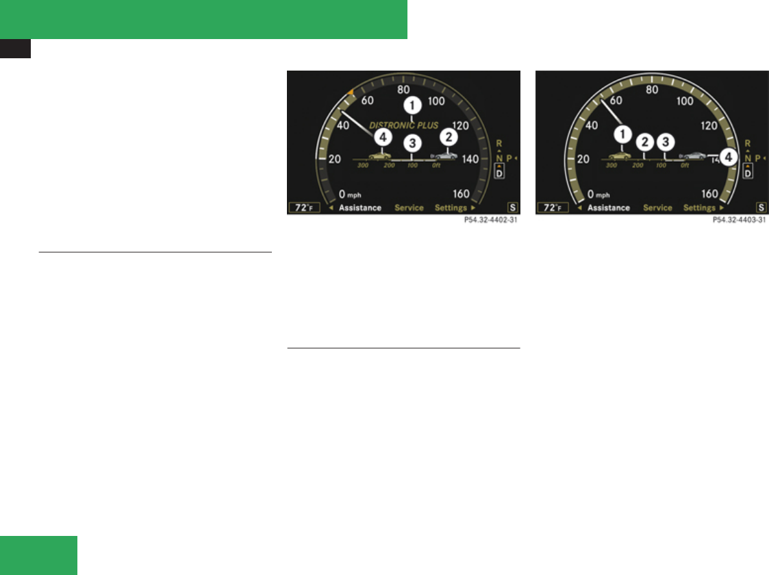
Driving systems
364
XPress ( or & to select the
Assistance menu.
XPress % or $ to select the Distance
Display function.
XPress #.
The DISTRONIC Plus distance graphic
appears and you will see one of the
following displays in the multifunction
display.
DISTRONIC Plus activated
When the DISTRONIC Plus is activated, you
will see the set speed in the multifunction
display for approximately 5 seconds. The
following display appears in the multifunction
display.
1DISTRONIC Plus activated
2Your vehicle
3Preset distance threshold to the
preceding vehicle
4Preceding vehicle, if detected
DISTRONIC Plus deactivated
When the DISTRONIC Plus is deactivated, you
will see the standard DISTRONIC Plus display
in the multifunction display.
1Preceding vehicle, if detected
2Actual distance to the preceding vehicle
3Preset distance threshold to the
preceding vehicle
4Your vehicle
Controls in detail
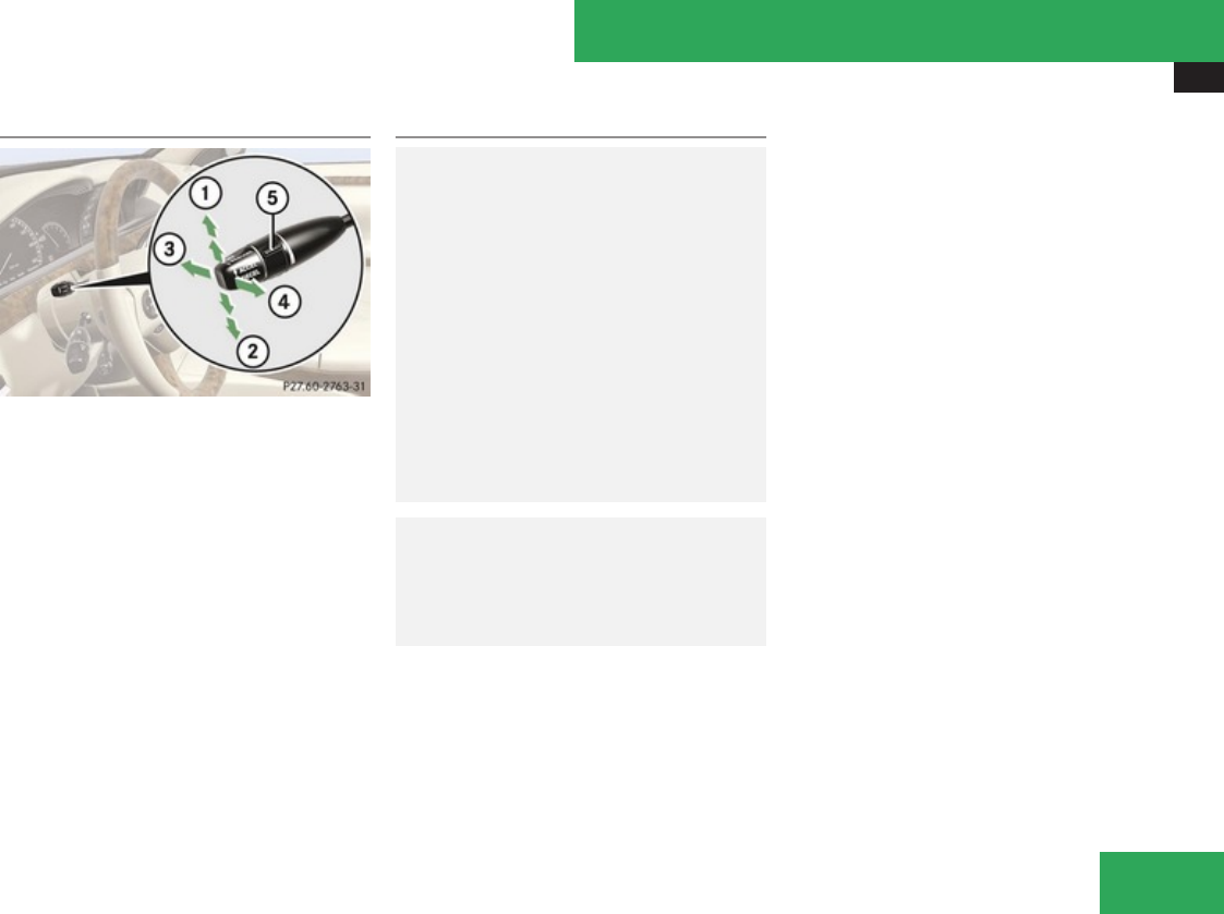
Driving systems
365
DISTRONIC Plus lever
1Setting current or higher speed
2Setting current or lower speed
3Deactivating the DISTRONIC Plus
4Activating the DISTRONIC Plus or
resuming to the last set speed
5Setting target distance
Activating DISTRONIC Plus
GWarning!
When the DISTRONIC Plus is braking, the
brake pedal is retracted (i.e. depressed
automatically). The pedals’ range of motion
must not be impeded by any obstacles:
RDo not place any objects in the footwell.
RMake sure that the floor mats and
carpets are securely in place.
RDo not rest your foot underneath the
brake pedal, as it could otherwise be
trapped.
You could otherwise cause an accident and
injure yourself and/or others.
GWarning!
When the DISTRONIC Plus is switched on,
the vehicle can be braked. You should
therefore switch off the DISTRONIC Plus if
the vehicle must be towed.
You can activate the DISTRONIC Plus when
the vehicle speed is above 20 mph
(30 km/h).
It is also possible to activate the DISTRONIC
Plus when the vehicle speed is below 20 mph
(30 km/h) and the DISTRONIC Plus has
detected a preceding vehicle.
The maximum vehicle speed you can set is
120 mph (Canada: 200 km/h).
When the DISTRONIC Plus is activated, the
set speed is indicated with a marker in the
speedometer dial (Y page 362).
If the DISTRONIC Plus is not activated after
the DISTRONIC Plus lever is pulled in
direction of arrow 4 (Y page 365), you will
see the message: DISTRONIC PLUS ---
mph (Canada: DISTRONIC PLUS --- kmh) in
the multifunction display.
In the following cases you cannot activate the
DISTRONIC Plus:
Rup to 2 minutes after starting the engine
Rif the engine is switched off
Rif you step on the brake pedal while driving
Rthe vehicle is secured with the electronic
parking brake
Rwhen the automatic transmission is in park
position P, reverse gear R, or neutral
position N
Rif the ESP® is switched off or has switched
off due to a malfunction
Rif the hood is open
Controls in detail
Z

Driving systems
366
Rif the driver’s door is open and the driver
has not fastened his or her seat belt
Rif the radar sensors are switched off
(Y page 253)
Switching on while driving
XTap the DISTRONIC Plus lever up 1 or
down 2 until desired speed is set.
The DISTRONIC Plus is switched on.
or
XPull the DISTRONIC Plus lever briefly in
direction of arrow 4 to call up the last set
speed, or if no speed is stored, to set and
store the current speed.
The DISTRONIC Plus is switched on.
XRemove your foot from the accelerator
pedal.
Your vehicle adapts its speed to the
preceding vehicle, observing the set speed
as a maximum value.
Below 20 mph (30 km/h), you can only switch
on the DISTRONIC Plus if the preceding
vehicle has been detected and is shown in the
multifunction display. If you no longer see the
preceding vehicle in the multifunction display
and if it is no longer detected because it has
changed lanes, for example, the DISTRONIC
Plus switches off and a signal sounds.
If you do not completely remove your foot
from the accelerator pedal, the message
DISTRONIC PLUS Override appears in the
multifunction display. The distance to a
slower-driving vehicle will not be set. You will
drive at the speed you dictate by pressing the
accelerator pedal.
Switching on when approaching a
stationary vehicle
If the preceding vehicle is stationary, you can
only switch on the DISTRONIC Plus if your
vehicle is also at a standstill.
XTap the DISTRONIC Plus lever up 1 or
down 2 until desired speed is set.
The DISTRONIC Plus is switched on.
or
XPull the DISTRONIC Plus lever briefly in
direction of arrow 4 to call up the last set
speed, or if no speed is stored, to set and
store the current speed.
The DISTRONIC Plus is switched on.
It is helpful to switch on the DISTRONIC Plus
display in the multifunction display
(Y page 363) since you can only switch on the
DISTRONIC Plus below a speed of 20 mph
(30 km/h) when a preceding vehicle is
detected.
You can adjust the set speed using the
DISTRONIC Plus lever and the target distance
using the distance setting switch on the
DISTRONIC Plus lever (Y page 370).
iIf the DISTRONIC Plus is switched off, the
PRE-SAFE® Brake (Y page 76) will warn of
an impending collision if this function has
been activated with the instrument cluster
control system (Y page 250).
Starting off
When the preceding vehicle starts off:
XRemove your foot from the brake pedal.
XPull the DISTRONIC Plus lever briefly in
direction of arrow 4.
or
XBriefly step on the accelerator pedal.
Your vehicle starts off and adapts its speed
to the preceding vehicle.
Driving
If there is no preceding vehicle, the
DISTRONIC Plus functions like the cruise
control (Y page 357).
When the DISTRONIC Plus detects that the
preceding vehicle is driving more slowly, it
Controls in detail

Driving systems
367
brakes the vehicle in order to keep the
distance specified by you.
When the DISTRONIC Plus detects that the
preceding vehicle is driving faster, it
accelerates the vehicle up to the set speed.
GWarning!
When you step on the brake pedal, you
switch off the DISTRONIC Plus except when
the vehicle is at a standstill. The DISTRONIC
Plus will no longer brake your vehicle. You
are always responsible for maintaining a
distance from other vehicles, observing
road speeds and braking well in advance.
Stopping
GWarning!
The braking effect of the DISTRONIC Plus
is canceled and the vehicle can start to roll
if
Rthe DISTRONIC Plus is switched off using
the DISTRONIC Plus lever
Ryou accelerate
Rthe DISTRONIC Plus system or the power
supply is malfunctioning, e.g. due to
battery failure
Rthe electrical components in the engine
compartment or the fuses have been
manipulated
Rthe battery is disconnected
GWarning!
Never get out of the vehicle while the
DISTRONIC Plus is switched on!
The DISTRONIC Plus must never be
operated or switched off by passengers or
from outside the vehicle.
The DISTRONIC Plus is not a substitute for
the electronic parking brake and may not
be used for parking.
When you get out of the vehicle or switch
off the engine, deactivate the DISTRONIC
Plus and secure the vehicle from rolling
away by engaging the electronic parking
brake.
When the DISTRONIC Plus detects that the
preceding vehicle is stopping, the vehicle
brakes until it also stops.
Once the DISTRONIC Plus has stopped the
vehicle and it is at a standstill, it remains
stationary; the brake pedal does not need to
be depressed.
After a short while, the vehicle is secured in
place by the electronic parking brake so that
the operating brake can be relieved of load.
Depending on the following distance set
using the distance setting switch on the
DISTRONIC Plus lever (Y page 370), the
vehicle will stop approximately 13.1 ft away
from the preceding vehicle.
Setting the current speed
XAccelerate or decelerate to the desired
speed.
XBriefly lift the DISTRONIC Plus lever in
direction of arrow 1 or depress in
direction of arrow 2 (Y page 365).
The current speed is set.
XRemove your foot from the accelerator
pedal.
iIf you do not take your foot off of the
accelerator pedal and continue to
accelerate past the set speed, the following
message will appear in the multifunction
display:
DISTRONIC PLUS Override
The distance to a slower moving vehicle in
front of you will not be set. Your vehicle
Controls in detail
Z

Driving systems
368
speed will then be determined only by the
accelerator pedal position.
Setting a higher speed
GWarning!
Keep in mind that it may take a brief
moment until the vehicle has made the
necessary adjustments.
Increase the set vehicle speed to a value
that the prevailing road conditions and legal
speed limits permit. Otherwise, sudden and
unexpected acceleration of the vehicle
could cause an accident and/or serious
injury to you and others.
You can increase the set speed in 1 mph
(Canada: 1 km/h) increments or in 5 mph
(Canada: 10 km/h) increments.
Adjustment in 1 mph (Canada: 1 km/h)
increments
XBriefly lift the DISTRONIC Plus lever up to
the resistance point in direction of arrow
1 (Y page 365).
XRelease the DISTRONIC Plus lever.
The vehicle set speed increases in
increments of 1 mph (Canada: 1 km/h)
each time you lift the DISTRONIC Plus lever
up to the resistance point.
Adjustment in 5 mph (Canada: 10 km/h)
increments
XBriefly lift the DISTRONIC Plus lever up past
the resistance point in direction of arrow
1 (Y page 365).
XRelease the DISTRONIC Plus lever.
The vehicle set speed increases in
increments of 5 mph (Canada: 10 km/h)
each time you lift the DISTRONIC Plus lever
up past the resistance point.
The new speed is set and the vehicle will
accelerate. Keep in mind that it may take a
brief moment until the vehicle has reached
the set speed.
Setting a lower speed
GWarning!
Keep in mind that it may take a brief
moment until the vehicle has made the
necessary adjustments.
Decrease the set vehicle speed to a value
that the prevailing road conditions and legal
speed limits permit. Otherwise, sudden and
unexpected deceleration of the vehicle
could cause an accident and/or serious
injury to you and others.
iWhen you use the DISTRONIC Plus lever
to decelerate, the brake system will
automatically brake the vehicle if the
engine’s braking power does not brake the
vehicle sufficiently.
You can reduce the set speed in 1 mph
(Canada: 1 km/h) increments or in 5 mph
(Canada: 10 km/h) increments.
Adjustment in 1 mph (Canada: 1 km/h)
increments
XBriefly press the DISTRONIC Plus lever
down to the resistance point in direction of
arrow 2 (Y page 365).
XRelease the DISTRONIC Plus lever.
The vehicle set speed decreases in
increments of 1 mph (Canada: 1 km/h)
each time you press the DISTRONIC Plus
lever down to the resistance point.
Controls in detail

Driving systems
369
Adjustment in 5 mph (Canada: 10 km/h)
increments
XBriefly press the DISTRONIC Plus lever
down past the resistance point in direction
of arrow 2 (Y page 365).
XRelease the DISTRONIC Plus lever.
The vehicle set speed decreases in
increments of 5 mph (Canada: 10 km/h)
each time you press the DISTRONIC Plus
lever down past the resistance point.
The new speed is set and the vehicle will
decelerate. Keep in mind that it may take a
brief moment until the vehicle has reached
the set speed.
Setting stored speed (Resume function)
GWarning!
The set speed stored in memory should
only be set again if prevailing road
conditions and legal speed limits permit.
Possible acceleration or deceleration
differences arising from returning to the
preset speed could cause an accident and/
or serious injury to you and others.
XBriefly pull the DISTRONIC Plus lever in
direction of arrow 4 (Y page 365).
The DISTRONIC Plus is activated and
resumes to the last set speed or, if no
speed is stored, it will set and store the
current speed.
XRemove your foot from the accelerator
pedal.
Deactivating DISTRONIC Plus
XDepress the brake pedal.
or
XBriefly push the DISTRONIC Plus lever in
direction of arrow 3 (Y page 365).
The last set speed is stored for later use.
The last stored speed is deleted from memory
when the engine is turned off.
The DISTRONIC Plus switches off
automatically when
Rthe vehicle is secured with the electronic
parking brake
Rthe vehicle speed falls below 20 mph
(30 km/h) and no preceding vehicle is
detected
Rthe ESP® is in operation, or switched off
with the ESP® switch (Y page 74), or the
ESP® has switched off due to a malfunction
Ryou shift the automatic transmission into
park position P, reverse gear R, or neutral
position N while driving
Rthe radar sensors are switched off
(Y page 253)
Rthe vehicle rolls backward
The marker for the set speed on the
speedometer dial go out, an acoustic signal
sounds, and the message DISTRONIC PLUS
Off appears in the multifunction display for
approximately 5 seconds.
If the vehicle has been stopped by the
DISTRONIC Plus and a malfunction occurs in
the DISTRONIC Plus system, the message
Brake Immediately will appear in the
multifunction display. Step on the brake
pedal immediately to prevent the vehicle from
rolling. The DISTRONIC Plus is then switched
off and the message disappears.
GWarning!
The DISTRONIC Plus switches off and
releases the brakes when the vehicle
decelerates below the minimum speed of
20 mph (30 km/h) by operation of the
system unless the DISTRONIC Plus detects
a vehicle directly ahead of you. At that time
the driver must apply the brakes in order to
Controls in detail
Z
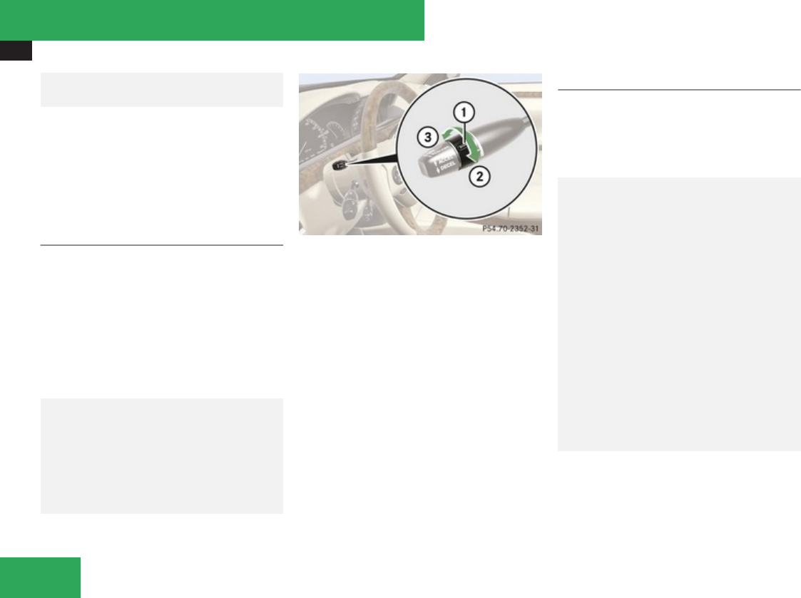
Driving systems
370
reduce vehicle speed further or bring it to
a stop.
Depressing the accelerator pedal does not
deactivate the DISTRONIC Plus. After a brief
acceleration (e.g. for passing), the
DISTRONIC Plus will resume the last set
speed.
Setting the following distance in
DISTRONIC Plus
You can set the specified following distance
for the DISTRONIC Plus by varying the time
setting between 1.0 and 2.0 seconds. Using
this time setting and the current speed of
your vehicle, the DISTRONIC Plus calculates
and sets the required following distance to
the preceding vehicle.
The set distance will be shown in the
multifunction display.
GWarning!
It is up to the driver to exercise discretion
to select the appropriate setting given road
conditions, traffic, driver’s preferred driving
style and applicable laws and driving
recommendations for safe following
distance.
1Distance setting switch for target
distance
2To increase target distance
3To decrease target distance
XIncreasing distance: Turn distance
setting switch 1 in direction of arrow 2.
Increasing the distance setting tells the
DISTRONIC Plus to maintain a greater
following distance to the preceding vehicle.
XDecreasing distance: Turn distance
setting switch 1 in direction of arrow 3.
Decreasing the distance setting tells the
DISTRONIC Plus to maintain a shorter
following distance to the preceding vehicle.
Driving with DISTRONIC Plus
This section describes a number of driving
situations where special precaution is
required on the part of the driver. Be prepared
to brake in such situations. Braking will
deactivate the DISTRONIC Plus system.
GWarning!
The DISTRONIC Plus works to maintain the
speed selected by the driver unless a
moving obstacle proceeding directly ahead
of it in the same travel direction is detected
(e.g. following another vehicle ahead of you
at your set distance).
This means that:
RYour vehicle can pass another vehicle
after you have changed lanes.
RWhile in a sharp turn or if the preceding
vehicle is in a sharp turn, the DISTRONIC
Plus could lose sight of the preceding
vehicle. Your vehicle could then
accelerate to the previously selected
speed.
Controls in detail
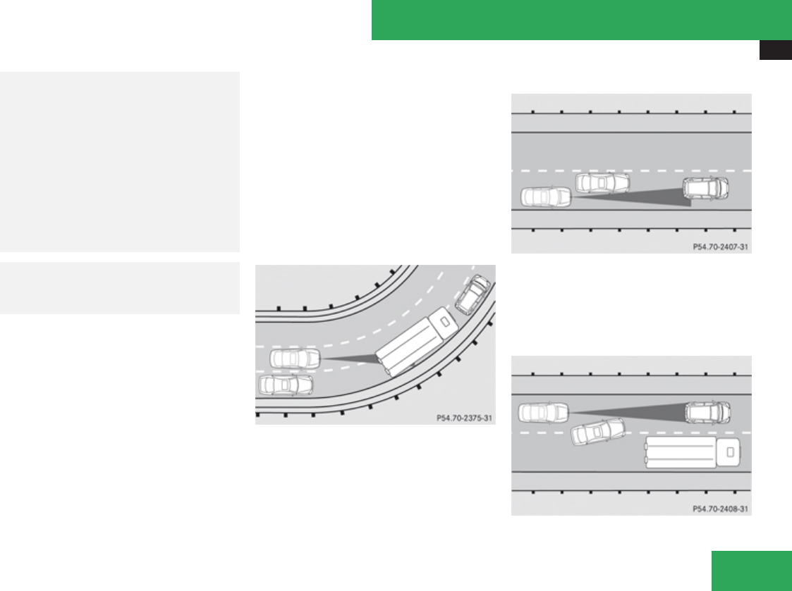
Driving systems
371
The DISTRONIC Plus regulates only the
distance between your vehicle and those
directly ahead of it. It may not register
stationary objects in the road, e.g.:
Ra stopped vehicle in a traffic jam
Ra disabled vehicle
Ran oncoming vehicle
The driver must always be alert, observe all
traffic and intercede as required by means
of steering or braking the vehicle.
GWarning!
The DISTRONIC Plus should not be used in
snowy or icy road conditions.
The most likely cause for a malfunctioning
system is a dirty sensor (located in the hood
grille and in the bumper), especially at times
of snow and ice or heavy rain.
In such a case, the DISTRONIC Plus will
switch off, and the message DISTRONIC
PLUS Currently Unavailable See Oper.
Manual appears in the multifunction display.
For cleaning and care of the sensors, see
(Y page 486).
iIf the message DISTRONIC PLUS
Currently Unavailable See Oper.
Manual disappears during driving and the
last speed stored flashes for approximately
5 seconds, the dirt (e.g. slush) has
dissolved; the DISTRONIC Plus is available
again.
Another cause might be that the radar
sensors have been manually switched off in
the instrument cluster control system. Please
verify that the radar sensors are switched on
(Y page 253).
Turns and bends
In turns or bends, the DISTRONIC Plus may
not detect a preceding vehicle, or it may
detect one too soon. This may cause your
vehicle to brake late or unexpectedly.
Offset driving
A vehicle traveling in your lane but offset from
your direct line of travel may not be detected
by the DISTRONIC Plus. There will be
insufficient distance to the preceding vehicle.
Lane changing
Controls in detail
Z
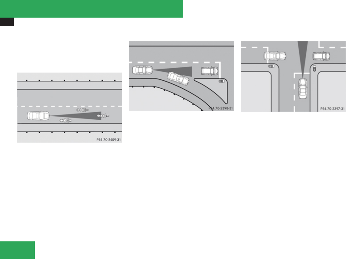
Driving systems
372
The DISTRONIC Plus has not yet detected the
vehicle changing lanes. There will be
insufficient distance to the lane-changing
vehicle.
Narrow vehicles
Because of their narrow profile, the vehicles
traveling near the outer edges of the lane
have not yet been detected by the DISTRONIC
Plus. There will be insufficient distance to the
preceding vehicles.
Obstacles and stationary vehicles
The DISTRONIC Plus does not brake for
obstacles or stationary vehicles. If, for
example, the vehicle detected in front of you
changes lanes to bypass an obstacle or
stationary vehicle in front of it, the
DISTRONIC Plus will not brake for the
obstacle or stationary vehicle.
Cross-traffic
The DISTRONIC Plus may inadvertently
detect crossing vehicles. If you switch on the
DISTRONIC Plus, for example, at a traffic light
with cross traffic, the vehicle may suddenly
start to drive off.
Controls in detail
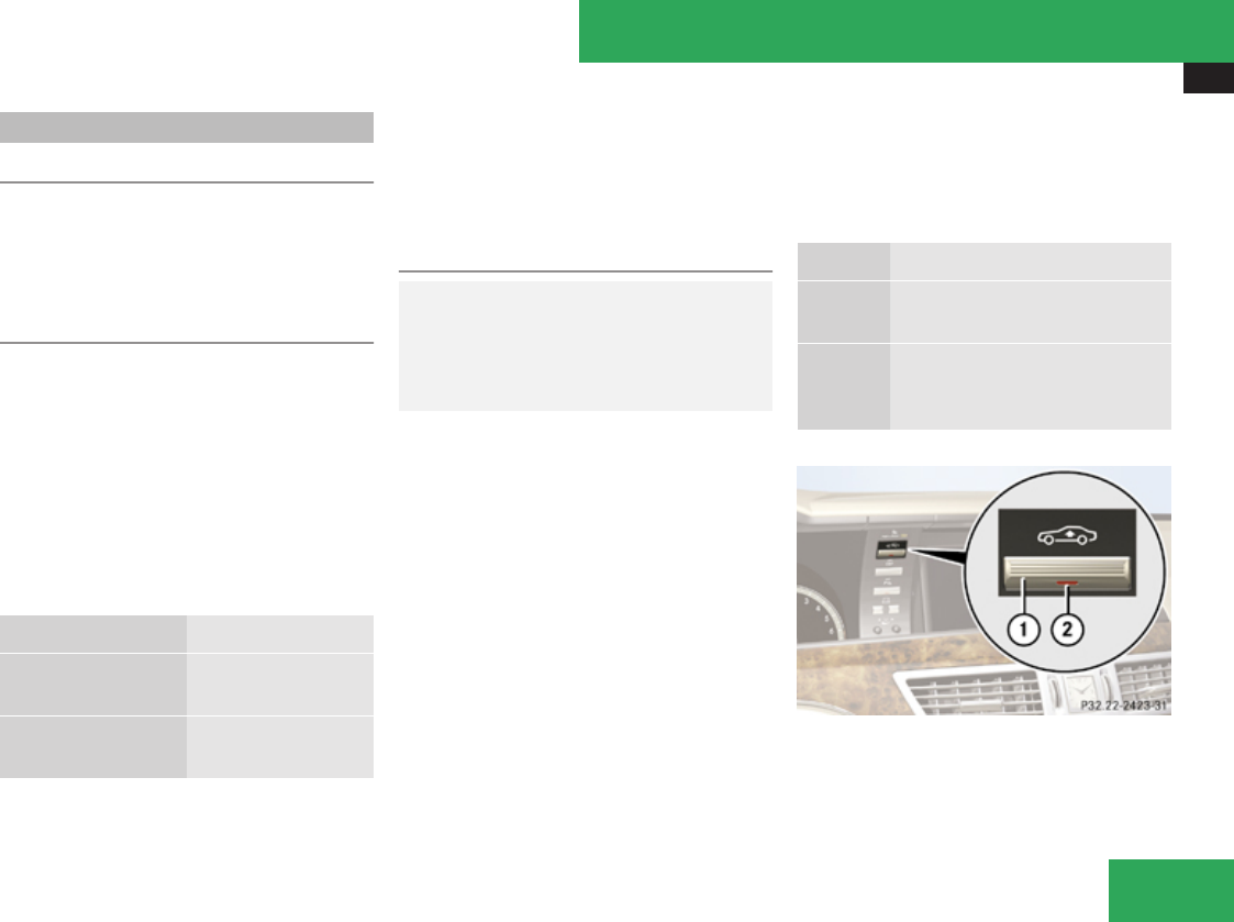
Driving systems
373
AIRMATIC
Introduction
The AIRMATIC consists of two components.
The Adaptive Damping System (ADS)
(Y page 373) and the vehicle level control
(Y page 373).
Adaptive Damping System (ADS)
The fine tuning of the damping is dependent
on:
Rroad surface conditions
Ryour driving style
Rvehicle loading
Ryour personal settings
The program mode selector switch (C/S)
(Y page 351) is used to adjust the suspension
tuning.
Driving program Suspension tuning
C Comfort comfortable
(default setting)
S Sport sporty
for dynamic driving
XStart the engine.
XPress the program mode selector switch
(C/S) (Y page 351) to select the desired
driving program.
Vehicle level control
GWarning!
To help avoid personal injury, keep hands
and feet away from wheel housing area, and
stay away from under the vehicle when
lowering the vehicle chassis.
Your vehicle automatically adjusts its ride
height to increase vehicle safety and to
reduce fuel consumption.
You can choose between raised or normal
level.
The vehicle chassis ride height is raised or
lowered according to the selected level
setting and to the vehicle speed. With
increasing speed, ride height is reduced by up
to approximately 0.8 in (20 mm). With
decreasing speed, the ride height is again
raised to the selected vehicle level.
iThese height adjustment are so small that
you may not notice any change.
Select the raised level only when required by
current driving conditions. Otherwise, the
handling may be impaired and the fuel
consumption may increase.
The following vehicle level settings can be
selected when the vehicle is stationary and
the engine is running:
Level
Normal For driving on normal roads. The
indicator lamp is off.
Raised For driving on rough roads or
with snow chains. The indicator
lamp is on
1Vehicle level control switch
2Indicator lamp
Controls in detail
Z

Driving systems
374
XStart the engine.
XBriefly press switch 1 to change from one
level setting to the other.
The message: Vehicle Rising appears in
the multifunction display when changing
from normal level to raised level. Indicator
lamp 2 is then lit. The message disappears
when the vehicle is raised.
XPress switch 1 again to lower the vehicle.
The setting raised is canceled and the vehicle
is lowered to the regular level automatically if
the vehicle speed is above 75 mph
(120 km/h) or if the vehicle speed stays
between 50 mph (80 km/h) and 75 mph
(120 km/h) for approximately 3 minutes.
Indicator lamp 2 in switch 1 goes out.
If you do not drive in this speed range, the
selected vehicle level setting remains stored
in memory even if the SmartKey is removed
from the starter switch.
Active Body Control (ABC)
The ABC system is an active, computer-
controlled system that hydraulically adjusts
the suspension at all four wheels in response
to various driving situations. It automatically
selects the optimum suspension tuning and
ride height for your vehicle.
GWarning!
When you turn off the engine, the entire
vehicle is lowered. You should therefore
make sure that no one is near the wheel
housing or under the vehicle when you turn
off the engine. Otherwise, parts of the
individuals body could be trapped.
! When you turn off the engine, the entire
vehicle is lowered. When parking, position
your vehicle in such a way that it will not
scrape against a curb, for example, when it
is lowered. Your vehicle could otherwise be
damaged.
iS 63 AMG and S 65 AMG only:
When you turn off the engine, the entire
vehicle is lowered by 0.2 in (5 mm).
Vehicle level control
GWarning!
To help avoid personal injury, keep hands
and feet away from wheel housing area, and
stay away from under the vehicle when
lowering the vehicle chassis.
Your vehicle adjusts its ride height
automatically to increase vehicle safety and
to reduce fuel consumption.
The vehicle chassis ride height is raised or
lowered according to the selected level
setting and to the vehicle speed. With
increasing speed, the ride height is reduced
by up to approximately 0.6 in (15 mm). With
decreasing speed, the ride height is again
raised to the selected vehicle level.
These height adjustments are so small that
you may not notice any change.
Controls in detail
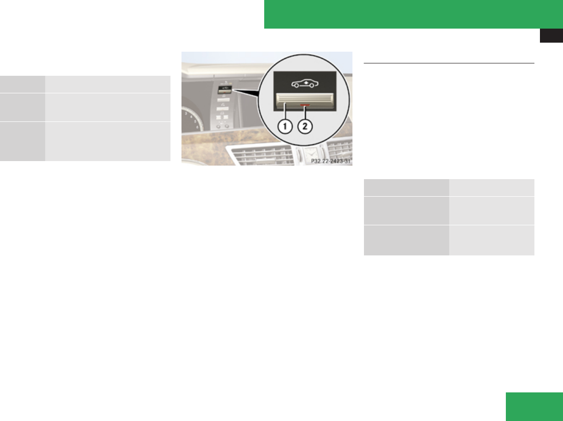
Driving systems
375
The following vehicle level settings can be
selected when the vehicle is stationary:
Level
Normal For driving on normal roads.
The indicator lamp is off.
Raised For driving on rough roads or
with snow chains. The indicator
lamp is on.
Select the “Raised” level setting only when
required by current driving conditions.
Otherwise the fuel consumption may
increase and/or the handling may be
impaired.
iThe selected vehicle level setting remains
stored in memory, even when the engine is
turned off and restarted.
1Vehicle level control switch
2Indicator lamp
XStart the engine.
Selecting a higher level
If indicator lamp 2 is off:
XPress switch 1.
Indicator lamp 2 comes on. The vehicle is
raised to a higher level.
Selecting a normal level
If indicator lamp 2 is on:
XPress switch 1.
Indicator lamp 2 goes out. The vehicle is
adjusted to a normal level.
Suspension tuning
The suspension tuning is set according to:
Ryour driving style
Rroad surface conditions
Rthe vehicle loading
Ryour choice of suspension style
The program mode selector switch (C/S)
(Y page 350) or (S/C/M) (Y page 350) is used
to adjust the suspension tuning.
Driving program Suspension tuning
C Comfort comfortable
(default setting)
S Sport
M Manual
sporty
for dynamic driving
XStart the engine.
XSelect the desired driving program.
Controls in detail
Z

Driving systems
376
All-wheel drive (4MATIC)
Your vehicle is equipped with all-wheel drive
(4MATIC). Both, the front and rear axles, are
powered at all times when the vehicle is being
operated. The 4MATIC improves traction in
conjunction with the ESP® (Y page 73) and
the Electronic Traction System (ETS/4-ETS)
(Y page 74).
GWarning!
If a drive wheel is spinning due to
insufficient traction:
RWhile driving off, apply as little throttle as
possible.
RWhile driving, ease up on the accelerator
pedal.
RAdapt your speed and driving style to the
prevailing road conditions.
Failure to observe these guidelines could
cause the vehicle to skid.
The 4MATIC cannot prevent accidents
resulting from excessive speed.
! Do not tow with one axle raised. Doing so
could damage the transfer case, which is
not covered by the Mercedes-Benz Limited
Warranty. All wheels must be on or off the
ground. Observe instructions for towing the
vehicle with all wheels on the ground.
! Only conduct operational or performance
tests on a two-axle dynamometer. If such
tests are necessary, contact an authorized
Mercedes-Benz Center. You could
otherwise seriously damage the brake
system and/or the transfer case which is
not covered by the Mercedes-Benz Limited
Warranty.
iIn winter operation, the maximum
effectiveness of the 4MATIC is only
achieved with winter tires (Y page 473) or
snow chains as required.
Parktronic system
The Parktronic system is an electronic
parking aid with ultrasonic sensors designed
to assist the driver during parking maneuvers.
It indicates the relative distance between the
vehicle and an obstacle visually and audibly.
The Parktronic system is activated
automatically when you
Rswitch on the ignition
and
Rrelease the electronic parking brake
or
Rstart the engine
and
Rshift the automatic transmission into drive
position D, reverse gear R, or neutral
position N
The Parktronic system deactivates at speeds
above approximately 11 mph (18 km/h). At
lower speeds, the Parktronic system switches
on again.
The Parktronic system also deactivates when
you shift the automatic transmission into
park position P or engage the electronic
parking brake and turn off the engine.
The Parktronic system monitors the
surroundings of your vehicle with six sensors
in the front bumper and four sensors in the
rear bumper.
Controls in detail
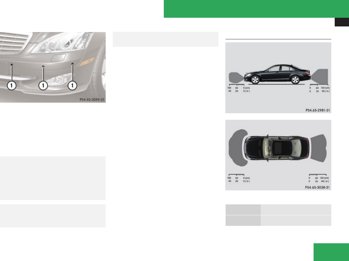
Driving systems
377
1Sensors in the front bumper (Only visible
without DISTRONIC Plus)
To function properly, the sensors must be free
of dirt, ice, snow and slush. Clean the sensors
regularly, being careful not to scratch or
damage the sensors, see “Cleaning the
Parktronic system sensors” (Y page 486).
GWarning!
The Parktronic is a supplemental system. It
is not intended to, nor does it replace, the
need for extreme care. The responsibility
during parking and other critical maneuvers
always remains with the driver.
GWarning!
Make sure no persons or animals are in or
near the area in which you are parking/
maneuvering. Otherwise, they could be
injured.
! Special attention must be paid to objects
with smooth surfaces or low silhouettes
(e.g. trailer couplings, painted posts,
elevated crossbars or road curbs). Such
objects may not be detected by the system
and can damage the vehicle.
During parking maneuvers, pay special
attention to objects located above or below
the height of the sensors (e.g. street curbs,
painted posts, or trailer hitches etc.). The
Parktronic system will not detect such
objects at close range and damage to your
vehicle or the object may result.
! Ultrasonic signals from outside sources
(e.g. truck air brakes, car wash, or
jackhammers) may impair the operation of
the Parktronic system.
Range of the sensors
Front sensors
Center approx. 40 in (100 cm)
Corners approx. 24 in (60 cm)
Controls in detail
Z
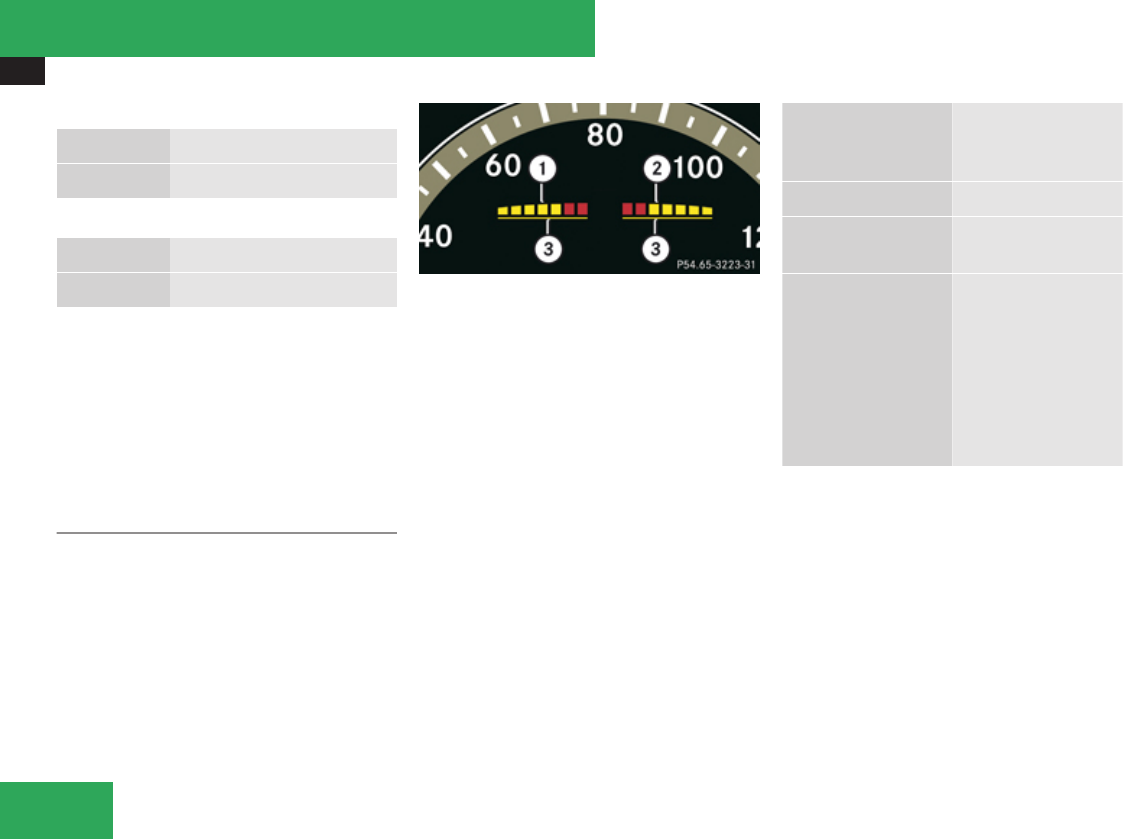
Driving systems
378
Rear sensors
Center approx. 48 in (120 cm)
Corners approx. 32 in (80 cm)
Minimum distance
Center approx. 8 in (20 cm)
Corners approx. 6 in (15 cm)
If the Parktronic system detects an obstacle
in this range, all the distance warning
segments illuminate and you hear a warning
signal. If the obstacle is closer than the
minimum distance, the actual distance may
no longer be indicated by the Parktronic
system.
Warning indicators
Visual signals indicate to the driver the
relative distance between the sensors and an
obstacle.
1Left side of the vehicle
2Right side of the vehicle
3Readiness indicators
Each warning indicator is divided into five
yellow and two red distance segments for
either side of the vehicle. The Parktronic
system is ready to measure when the yellow
readiness indicators 3 are illuminated.
The current transmission position determines
which warning indicator will be activated.
Current
transmission
position
Warning indicator
DFront area activated
RFront and rear area
activated
NWith the electronic
parking brake
engaged: neither
activated
With the electronic
parking brake
released: front and
rear area activated
As your vehicle approaches an object, one or
more distance segments will illuminate,
depending on the distance. When the seventh
distance segment illuminates, you have
reached the minimum distance.
RFront area: An intermittent acoustic
warning will sound as the first red distance
segment illuminates and a constant
acoustic warning lasting a maximum of
2 seconds will sound for the second red
distance segment. The signal is canceled
Controls in detail
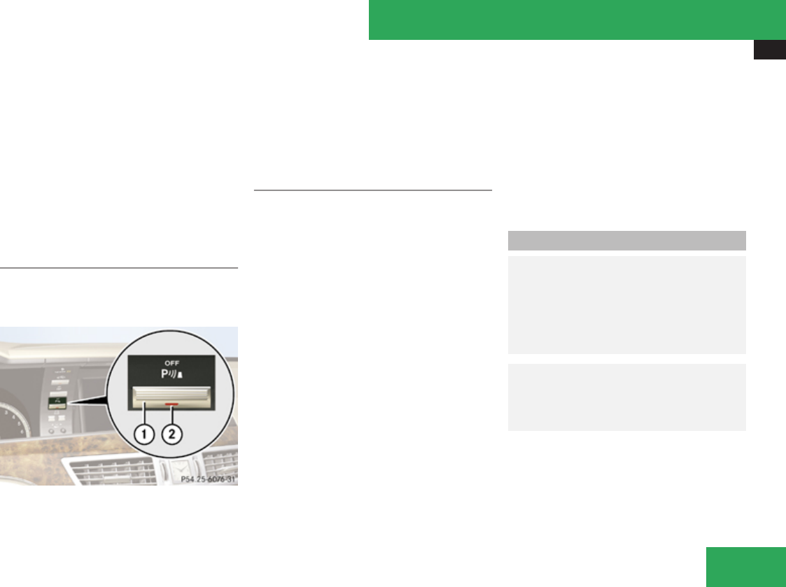
Driving systems
379
when the automatic transmission is shifted
into park position P.
RRear area: An intermittent acoustic
warning will sound as the first red distance
segment illuminates and a constant
acoustic warning lasting a maximum of
2 seconds will sound for the second red
distance segment. The signal is canceled
when the automatic transmission is shifted
into drive position D or park position P.
Switching the Parktronic system on/off
The Parktronic system switches on
automatically when the ignition is switched
on.
1Parktronic switch
2Indicator lamp
XSwitching off Parktronic system: Press
Parktronic switch 1.
Indicator lamp 2 comes on.
XSwitching on Parktronic system: Press
Parktronic switch 1 again.
Parktronic system malfunction
There is a malfunction in the Parktronic
system, if only the red distance segments
illuminate and an acoustic warning sounds.
The Parktronic system will switch off
automatically after 20 seconds and indicator
lamp 2 in Parktronic switch 1 comes on.
XHave the Parktronic system checked at an
authorized Mercedes-Benz Center as soon
as possible.
If only the red distance segments illuminate
and no acoustic warning sounds, the
Parktronic system sensors are dirty (e.g. dirt,
ice, snow and slush) or there is an
interference from other radio or ultrasonic
signals (e.g. truck air brakes, car wash, or
jackhammers). The Parktronic system will
switch off automatically after 20 seconds and
indicator lamp 2 in Parktronic switch 1
comes on.
XSwitch off the ignition.
XClean the Parktronic system sensors
(Y page 486).
XSwitch on the ignition.
or
XCheck the Parktronic system operation at
another location to rule out interference
from outside radio or ultrasonic signals.
Park Assist
GWarning!
The Park Assist is a supplemental system.
It is not intended to, nor does it replace, the
need for extreme care. The responsibility
during parking and other critical maneuvers
always remains with the driver.
GWarning!
Make sure no persons or animals are in the
area in which you are maneuvering. You
could otherwise injure them.
! Special attention must be paid to objects
with smooth surfaces or low silhouettes
(e.g. trailer couplings, painted posts,
elevated crossbars or road curbs). Such
Controls in detail
Z

Driving systems
380
objects may not be detected by the system
and can damage the vehicle.
iUSA only:
This device has been approved by the FCC
as a “Vehicular Radar System”. The radar
sensor is intended for use in an automotive
radar system only. Removal, tampering, or
altering of the device will void any
warranties, and is not permitted by the
FCC. Do not tamper with, alter, or use in
any non-approved way.
Any unauthorized modification to this
device could void the user’s authority to
operate the equipment.
iCanada only:
This device complies with RSS-210 of
Industry Canada. Operation is subject to
the following two conditions:
1. This device may not cause interference,
and
2. this device must accept any
interference received, including
interference that may cause undesired
operation of the device.
Removal, tampering, or altering of the
device will void any warranties, and is not
permitted. Do not tamper with, alter, or use
in any non-approved way.
Any unauthorized modification to this
device could void the user’s authority to
operate the equipment.
When traveling in Canada in a vehicle not
registered in Canada, you must switch off the
radar sensor system (Y page 253). Canadian
law does not permit the use of the radar
sensor system for vehicles from outside of
Canada. When you switch off the radar sensor
system, the following functions are
deactivated:
RPark Assist
RBAS Plus (Y page 70)
RPRE-SAFE® Brake (Y page 76)
RDISTRONIC Plus (Y page 360)
RAdvanced Parking Guidance (Y page 383)
RBlind Spot Assist (Y page 392)
! The operational function of the Park
Assist system can be affected by dirty
sensors, especially at times of snow and
ice.
Make sure that the area on the bumpers
around the sensors is free of dirt, ice and/
or slush, otherwise the Park Assist may not
function properly.
For cleaning the driving systems sensors, see
(Y page 486).
! High-frequency sources such as toll
stations, speed measuring systems, etc.
can cause the Park Assist system to
malfunction. You can switch off the Park
Assist using the Park Assist button or
switch off the radar sensors with the
instrument cluster control system to
prevent possible malfunction.
The Park Assist is an electronic parking aid
with radar sensors that helps you while
parking. It visually and audibly indicates the
relative distance between the vehicle and an
obstacle.
The Park Assist is automatically activated
when the engine is running and the automatic
transmission is in drive position D, reverse
gear R or neutral position N.
The Park Assist deactivates at speeds over
approximately 10 mph (16 km/h). At lower
speeds the Parktronic system turns on again.
The Park Assist is also switched off when you
set the automatic transmission into park
position P or switch off the engine.
While the automatic transmission is in neutral
position N, the Park Assist is switched off if
Controls in detail
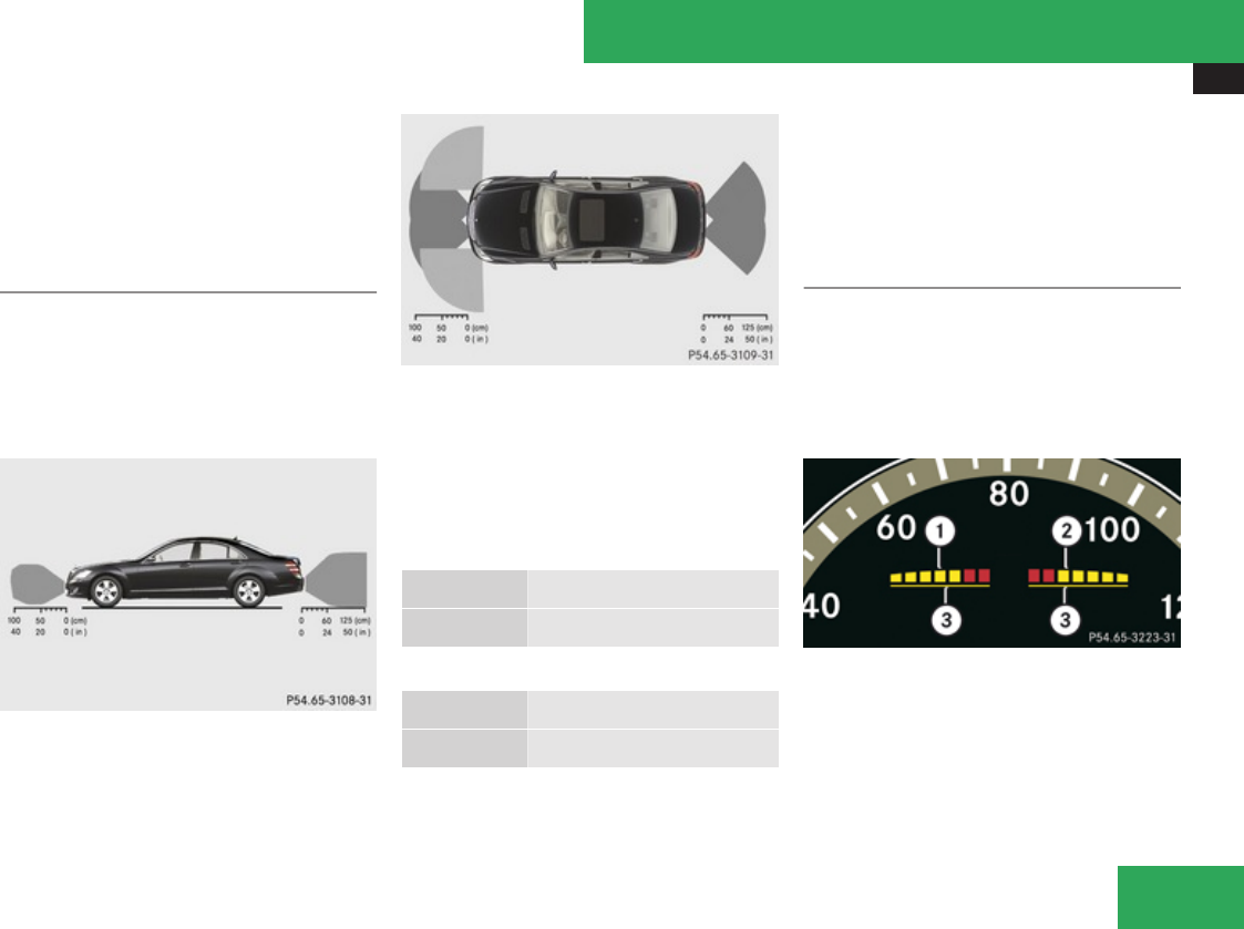
Driving systems
381
you secure the vehicle in place with the
electronic parking brake.
The Park Assist monitors the surroundings of
your vehicle with four sensors in the front
bumper and two sensors in the rear bumper.
Range of the sensors
The sensors of the Park Assist system are
integrated in the front and rear bumpers.
Make sure that the bumpers are clear of dirt,
ice and slush in the area of the sensors, as
otherwise, Park Assist may not function
properly, see (Y page 486).
Due to the sensors’ broad detection range, it
is possible that the Park Assist also detects
and issues a warning for obstacles in the
ground, e.g. sewer canal covers, rails, bumps
in the road or gutters or obstacles moving
upward quickly, e.g. rolling garage doors.
Front sensors
Center approx. 40 in (100 cm)
Corners approx. 24 in (60 cm)
Rear sensors
Center approx. 50 in (125 cm)
Corners approx. 24 in (60 cm)
! While parking, pay particular attention to
objects over or underneath the sensors,
e.g. flower boxes, an elevated crossbar or
a trailer tow hitch. The Park Assist does not
detect such nearby objects. You could
otherwise damage the vehicle or the
objects.
Warning indicators
Visual signals indicate to the driver the
relative distance between the sensors and an
obstacle.
The warning indicator for the front area is in
the instrument cluster. The warning indicator
for the rear area is on the roof liner in the rear.
1Left side of the vehicle
2Right side of the vehicle
3Readiness indicators
Each warning indicator is divided into five
yellow and two red distance segments for
either side of the vehicle.
Controls in detail
Z

Driving systems
382
If yellow readiness indicators 3 under the
distance segments are lit, the Park Assist is
ready to measure.
The current transmission position determines
which warning indicators will be activated.
Current
transmission
position
Warning indicator
DFront area activated
RFront and rear area
activated
NWith the electronic
parking brake
engaged: neither
activated.
With the electronic
parking brake
released: front and
rear area activated.
PNeither activated
As your vehicle approaches an object, one or
more distance segments will illuminate,
depending on the distance. When the seventh
distance segment illuminates, you have
reached the minimum distance.
Front area:
As soon as the first red distance segment
illuminates, you will hear an intermittent
warning tone for approximately 2 seconds.
Once the second red distance segment
illuminates, you will hear a continuous
warning tone. You have reached the minimum
distance. The signal is canceled when the
automatic transmission is in park position P
or neutral position N with the electronic
parking brake engaged.
Rear area:
As soon as the first red distance segment
illuminates, you will hear an intermittent
warning tone for approximately 2 seconds.
Once the second red distance segment
illuminates, you will hear a continuous
warning tone. You have reached the minimum
distance. The signal is canceled when the
automatic transmission is in drive position
D, park position P, or neutral position N with
the electronic parking brake engaged.
iDuring strong rainfall, the warning
indicators and warning tones may be
triggered, for example, by water splashing
into the area of the sensors.
Collision warning
The Park Assist can detect obstacles from a
considerable distance. If you drive in reverse
towards an obstacle, you will hear a warning
tone. You must then brake in order to avoid a
collision. The warning tone for a collision will
not sound when the vehicle is at a standstill
very close to the obstacle. In this case, you
will hear a corresponding tone for the warning
indicator in the rear area.
iDuring strong rainfall, the collision
warning may be triggered, for example, by
water splashing into the area of the
sensors.
Switching Park Assist system on/off
The Park Assist system can be switched off
manually.
The Park Assist button with the indicator lamp
is located on the control panel on the right-
hand side of the instrument cluster.
iWhen the indicator lamp is on, the Park
Assist system is switched off.
Controls in detail
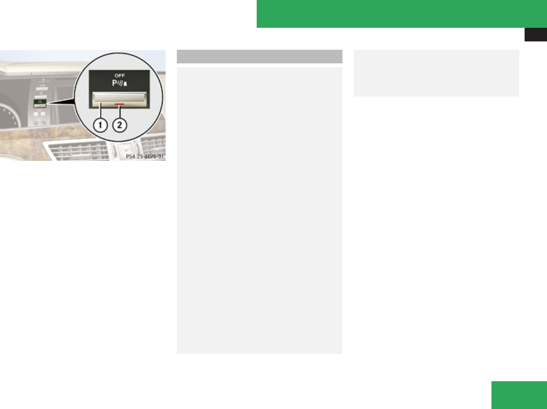
Driving systems
383
1Park Assist button
2Indicator lamp
XSwitching off: Press button 1.
Indicator lamp 2 comes on.
XSwitching on: Press button 1 again.
Indicator lamp 2 goes out.
The Park Assist system is automatically
switched on when the ignition and radar
sensors (Y page 253) are switched on.
Advanced Parking Guidance
GWarning!
The Advanced Parking Guidance is only an
aid and may display parking spaces that are
not suitable e.g. due to parking regulations,
unsuitable road/ground surfaces,
driveways, entrances/exits, etc.
The Advanced Parking Guidance only
shows a representation of the parking
space in the instrument cluster display as
parking space is first initially measured
when driving past. Subsequent changes to
the parking space are not taken into
account, e.g. if the position of the vehicle
parked in front of or behind the space
changes or objects in the parking space are
moved. Moving objects are not shown, e.g.
pedestrians or vehicles driving past. The
Advanced Parking Guidance does not
relieve you of the responsibility to pay
attention. If you only rely on the Advanced
Parking Guidance, you may cause an
accident and injure yourself and others.
You are always responsible for safety and
must continue to pay attention to your
immediate surroundings when parking and
maneuvering.
GWarning!
Make sure no persons or animals are in the
area in which you are maneuvering. You
could otherwise injure them.
! Special attention must be paid to objects
with smooth surfaces or low silhouettes
(e.g. trailer couplings, painted posts,
elevated crossbars or road curbs). Such
objects may not be detected by the system
and can damage the vehicle.
iUSA only:
This device has been approved by the FCC
as a “Vehicular Radar System”. The radar
sensor is intended for use in an automotive
radar system only. Removal, tampering, or
altering of the device will void any
warranties, and is not permitted by the
FCC. Do not tamper with, alter, or use in
any non-approved way.
Any unauthorized modification to this
device could void the user’s authority to
operate the equipment.
Controls in detail
Z

Driving systems
384
iCanada only:
This device complies with RSS-210 of
Industry Canada. Operation is subject to
the following two conditions:
1. This device may not cause interference,
and
2. this device must accept any
interference received, including
interference that may cause undesired
operation of the device.
Removal, tampering, or altering of the
device will void any warranties, and is not
permitted. Do not tamper with, alter, or use
in any non-approved way.
Any unauthorized modification to this
device could void the user’s authority to
operate the equipment.
! The operation and functionality of the
Advanced Parking Guidance can be
affected or impaired by dirty sensors,
especially at times of snow and ice.
Make sure that the area on the bumpers
around the sensors is free of dirt, ice and/
or slush, otherwise Advanced Parking
Guidance may not function properly.
The Advanced Parking Guidance is an
electronic parking aid equipped with radar
sensors that scan the area on both sides of
vehicle. When suitable parking space is found
it is shown in the display and you receive
steering instructions for parking in that
space.
When traveling in Canada in a vehicle not
registered in Canada, you must switch off the
radar sensor system (Y page 253). Canadian
law does not permit the use of the radar
sensor system for vehicles from outside of
Canada. When you switch off the radar sensor
system, the following functions are
deactivated:
RAdvanced Parking Guidance
RBAS Plus (Y page 70)
RPRE-SAFE® Brake (Y page 76)
RDISTRONIC Plus (Y page 360)
RPark Assist (Y page 379)
RBlind Spot Assist (Y page 392)
Use the Advanced Parking Guidance for
parking spaces that are
Rparallel to the direction of travel
Rlocated on straight streets, i.e. not in
curves
Ron the same level as the street, i.e. not on
sidewalks, for example. Flat curbs may
possible not be detected by the Advanced
Parking Guidance.
Parking instructions:
ROn narrow streets, drive by the parking
space as close as possible.
RParking spaces that are dirty, overgrown or
located in front of trailers may not be
detected correctly.
RAlso observe the Park Assist warning
indicator (Y page 379) while the Advanced
Parking Guidance is active.
RHow well your vehicle will be parked after
completion of the Advanced Parking
Guidance depends on the position and
shape of the vehicles parked in front of and
behind the parking space as well as the
conditions of the immediate surroundings.
In certain cases, the Advanced Parking
Guidance may guide you too far into the
parking space or not far enough. If this is
the case, cancel the parking procedure
with the Advanced Parking Guidance and
correct the vehicle position yourself.
Detecting a parking space
The Advanced Parking Guidance is active
when driving forward. The system operates at
Controls in detail
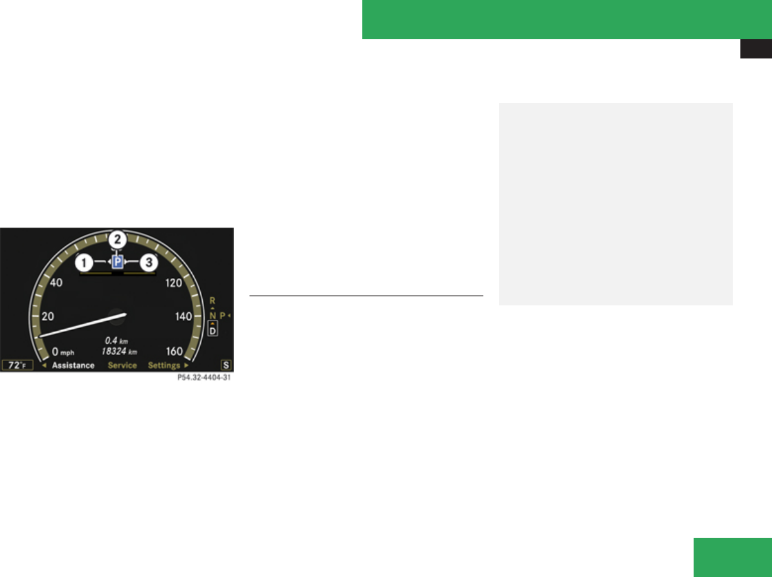
Driving systems
385
a vehicle speed of up to 25 mph (40 km/h)
and automatically scans for and measures
potential parking spaces on both sides of the
vehicle. At a vehicle speed of below 10 mph
(16 km/h), you see the white parking space
symbol as a system display in the instrument
cluster. As soon as the Advanced Parking
Guidance has detected a suitable parking
space, the parking space symbol changes to
blue.
1Detected parking spaces on the left
2Parking space symbol
3Detected parking spaces on the right
In order to be detected by the Advanced
Parking Guidance, a parking space must be:
Rclosed-in at the rear
Rparallel to the direction of travel
Rat least 5 ft (1.5 m) wide
Rat least 3.5 ft (1.0 m) longer than your
vehicle is
A parking space is shown in the display when
driving by until you have reached a distance
of 50 ft (15 m) from the space. the Advanced
Parking Guidance only shows parking spaces
on the front-passenger side of the vehicle
unless you activate the driver’s side (left) turn
signal. If you would like to park on the driver’s
side, the left turn signal must remain on until
the reverse gear is engaged.
Parking
The following describes how you can park on
the front-passenger side. Parking on the
driver’s side is performed reversed left to
right.
If the Advanced Parking Guidance detects an
obstacle behind the vehicle during the
parking procedure, you will hear an audible
warning. Stop the vehicle immediately. The
parking space and the lane flash in the
instrument cluster. Only continue driving/
parking after you have made sure that this is
possible to do in a safe manner. If the
Advanced Parking Guidance no longer
detects any obstacles, the display in the
instrument cluster stops blinking. You may
continue the parking procedure.
GWarning!
The Advanced Parking Guidance is only an
aid and may not detect all obstacles. At
corners or near smooth surfaces, the
Advanced Parking Guidance may not detect
an object correctly. The Advanced Parking
Guidance does not relieve you of the
responsibility to pay attention. You are
always responsible for safety and must
continue to pay attention to your
immediate surroundings when parking and
maneuvering. Otherwise, you could
endanger yourself and others.
XBring the vehicle to a standstill as long as
the desired parking space is displayed by
Controls in detail
Z
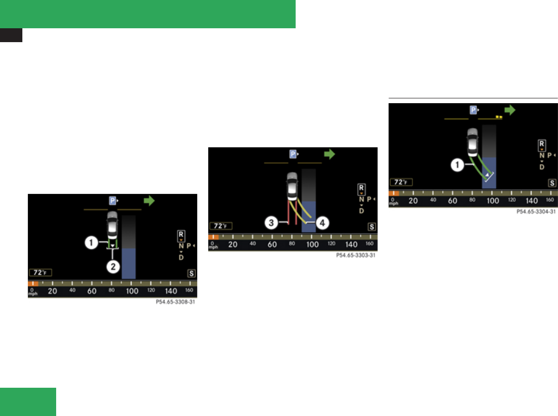
Driving systems
386
the blue parking space symbol in the
instrument cluster.
XShift the automatic transmission into
reverse gear R.
The message Check Surroundings
Press ’OK’ to Confirm appears in the
multifunction display.
XPress # on the multifunction steering
wheel to confirm.
The display in the instrument cluster
changes to the Advanced Parking
Guidance.
1Green lane
2White bracket indicates the stopping
position
XWhere necessary, depending on the
distance to the parking space, back up in a
straight line a short distance.
This is indicated by a green lane 1.
XBack up until you hear an audible warning,
then stop.
The stopping position has been reached,
indicated by a white bracket 2.
3Red lane indicates the current steering
wheel position
4Yellow lane indicates the required
steering wheel position
XWhen the vehicle is stationary, turn the
steering wheel until red lane 3 matches
up with yellow lane 4.
Lane 4 then turns green. If the parking
space is located within the display range, a
white bracket with an arrow for the target
position is shown at the end of the green
lane.
Driving into the parking space
1Green lane indicates the correct steering
wheel position
XMaintain the steering wheel position and
carefully back up.
XStop as soon as you hear the audible
warning.
The vehicle has reached the position for
countersteering.
Controls in detail
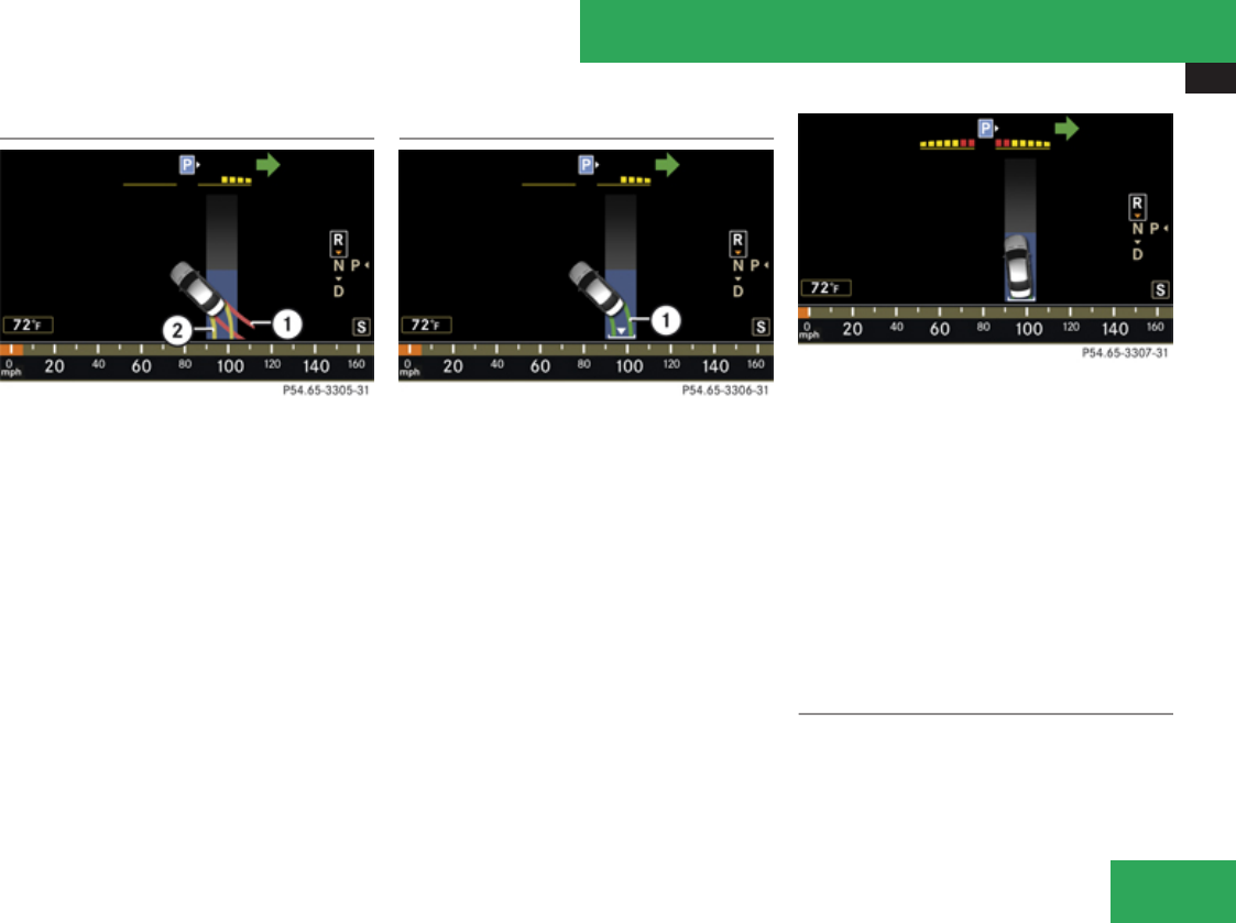
Driving systems
387
Countersteering
1Red lane indicates the current steering
wheel position
2Yellow lane indicates the required
steering wheel position
XWhen the vehicle is stationary, turn the
steering wheel until red lane 1 matches
up with yellow lane 2.
Lane 2 then turns green and a white arrow
and a white bracket are shown to indicate
the target position.
Reaching end position
1Green lane indicates the correct steering
wheel position
XMaintain the steering wheel position and
carefully back up until the end position has
been reached.
The message Parking Guidance
Finished appears in the multifunction
display and you will hear an audible
warning.
If the distance to the rear is too short, you
will also be audibly warned by the Park
Assist system (Y page 379).
End position
Depending on the size of the parking space,
the vehicle may be positioned at an angle in
the parking space. The Advanced Parking
Guidance guides you close to the rear limit of
the parking space where possible.
XAdjust the end position by maneuvering as
needed.
XObserve the Park Assist display
(Y page 379).
Canceling the Advanced Parking
Guidance
XPress the Park Assist button (Y page 383).
The Advanced Parking Guidance is
immediately canceled and the Park Assist
is deactivated. No message is shown in the
multifunction display.
Controls in detail
Z
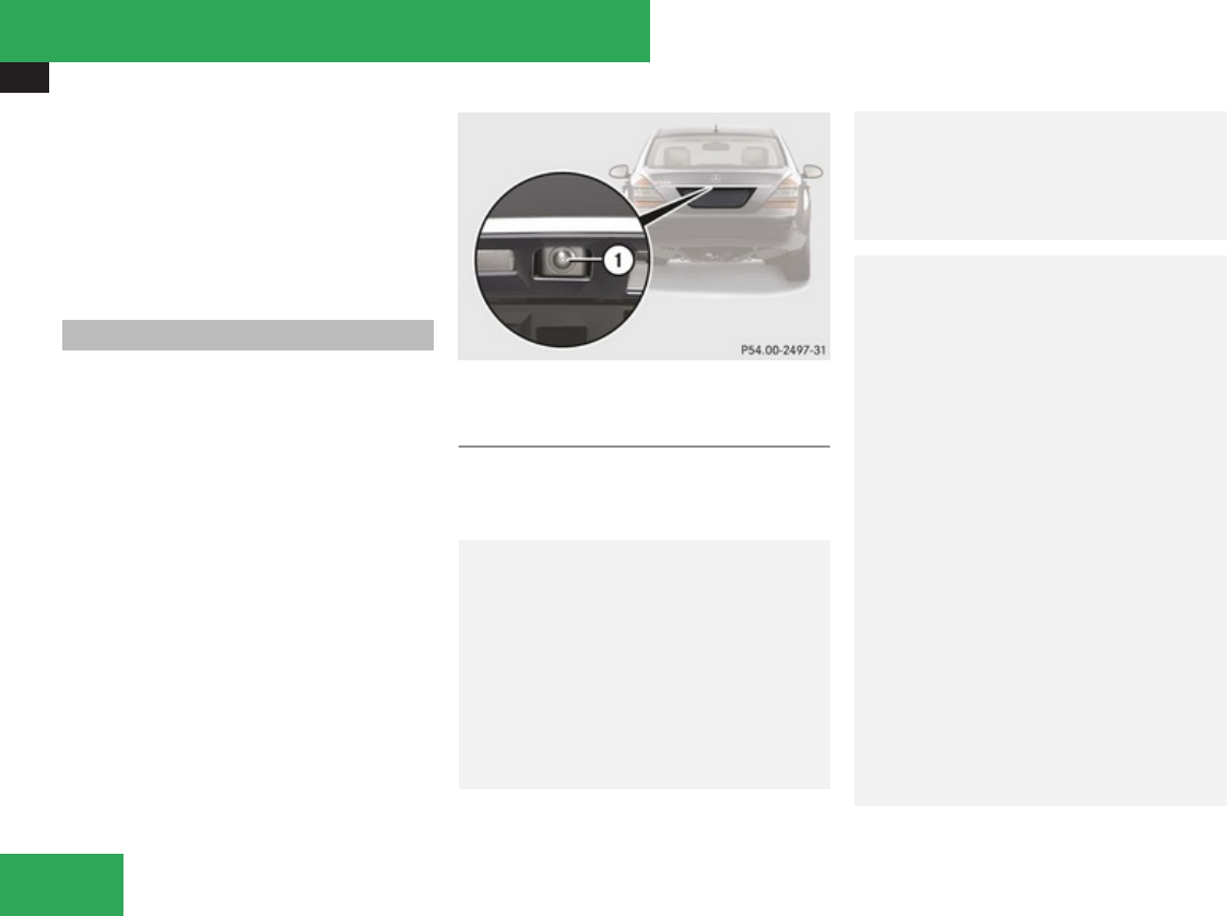
Driving systems
388
The Advanced Parking Guidance is
automatically canceled if guidance into the
parking space is no longer possible or if an
error occurs.
The parking space symbol disappears and the
message Parking Guidance Canceled
appears in the multifunction display.
Rear view camera
The rear view camera is an electronic and
visual parking aid. It shows you the area
behind the vehicle on the COMAND system
display.
In addition, the rear view camera contains
guide lines to help you with driving in reverse.
The area behind the vehicle is displayed as a
reverse-mirror image similar to the view in a
rear view mirror.
1Rear view camera
View through the rear view camera
iThe image from the rear view camera is
shown mirror-inverted on the COMAND
system display.
GWarning!
Please note that objects which do not touch
the ground, such as the bumper of a vehicle
parked behind you, a trailer hitch, or the
back of a truck, may appear to be further
away than they actually are. In this case,
you should not use the guide lines to judge
distance. The use of the guide lines to judge
distance increases the risk of impacting the
objects.
GWarning!
Make sure no persons or animals are in or
near the area in which you are parking/
maneuvering. Otherwise, they could be
injured.
GWarning!
The rear view camera is a supplement
system. It is not intended to, nor does it
replace, the need for extreme care. The
responsibility during parking and other
driving maneuvers always remains with the
driver.
The rear view camera may show obstacles
with a distorted perspective, incorrectly or
not at all.
Special attention must be paid to objects
outside of the camera’s field of view such
as those located very close to or below the
rear bumper, or above the recessed grip of
the luggage compartment lid. Such objects
may not be detected by the system and can
damage the vehicle.
The rear view camera does not warn you
about impending collisions with objects.
The driver is always responsible for safety
and must continue to pay attention to the
immediate surroundings while parking or
Controls in detail

Driving systems
389
maneuvering the vehicle. This applies not
only to the area behind the vehicle, but also
to the area in front of and to the sides of
the vehicle. Failure to do so could result in
injury to persons and/or damage to the
vehicle or other property. We also
recommend that the driver uses the
Parktronic system, Park Assist, or
Advanced Parking Guidance when parking
or maneuvering the vehicle.
GWarning!
The rear view camera either will not
function or will not function to its full
capability if
Rthe trunk lid is open or not completely
closed
Rit is raining or snowing heavily, or if there
is thick fog
Rin a very dark area
Rthe camera is exposed to a very bright
white light (white stripes may appear on
the COMAND system display)
Rthe immediate surroundings are
illuminated with fluorescent light (the
COMAND system display can flicker)
Rthere is a sudden change in temperature,
e.g. if you drive into a heated garage from
the cold (lens condensation)
Rthe camera lens is dirty or covered
Rthe rear of your vehicle is damaged
In this case, have the position and setting
of the camera checked by a qualified
specialist workshop. Mercedes-Benz
recommends that you contact a
Mercedes-Benz Center for this purpose.
Do not use the rear view camera if the roads
are icy, slippery or covered with snow. The
vehicle could slip causing the actual vehicle
position to deviate from the one shown on
the COMAND system display. This may
cause injury to you or others, or damage the
vehicle or objects.
Mounting tires/rims of other specification
than the original equipment tires/rims may
impair the function of the rear view camera.
Contact an authorized Mercedes-Benz
Center.
GWarning!
Use of rear view camera can be dangerous
if you are color-blind or have impaired color
vision.
Only use rear view camera if you can see
and distinguish all colored guide lines
shown by rear view camera on the
COMAND system display.
Switching on rear view camera
iThe rear view camera must be activated
in the instrument cluster control system in
order for it to be switched on.
XSwitch on the ignition.
XSwitch on the COMAND system.
XShift into reverse gear R.
The COMAND system display will show the
area behind the vehicle with guide lines.
GWarning!
Please note that objects which do not touch
the ground, such as the bumper of a vehicle
parked behind you, a trailer hitch, or the
back of a truck, may appear to be further
away than they actually are. In this case,
you should not use the guide lines to judge
distance as the use of the guide lines to
judge distance increases the risk of
impacting the objects.
Even when the object you approach is
directly on the ground (and nothing on the
Controls in detail
Z
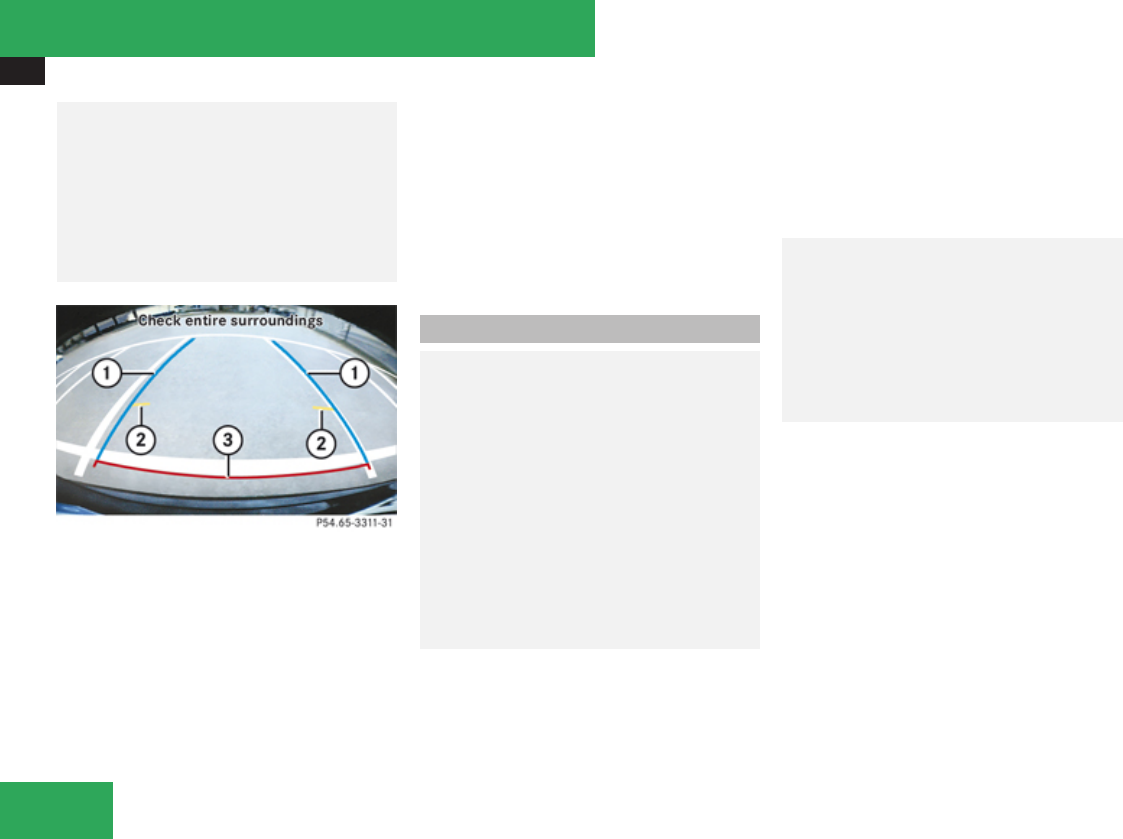
Driving systems
390
object extends above the ground beyond
the object’s contours directly touching the
ground) and no objects that do not touch
the ground, such as the bumper of a vehicle
parked behind you, a trailer hitch, or the
back of a truck are in the path, do not
approach the object on the ground any
closer than the red guide line.
1Blue guide lines for vehicle width
2Yellow 39 in (1 m) guide line
3Red 10 in (0.25 m) guide line
The red 10 in (0.25 m) guide line 3, the
yellow 39 in (1 m) guide line 2 correspond
to the relevant distance from the rear of the
vehicle. The blue guide line for vehicle width
1 show the required width for the vehicle.
iIf you activate a different function on the
driver’s COMAND system controls while
reverse parking or parallel parking, the
image from the rear view camera is
interrupted.
To reactivate the rear view camera, take
the vehicle out of reverse gear and then re-
engage reverse gear again.
Night View Assist
GWarning!
The Night View Assist is only an aid to
support you while driving and cannot
substitute your careful attention. Do not
rely on the display of the Night View Assist;
instead, continue to look through the
windshield. You are always responsible for
safety and must drive in accordance with
traffic conditions. Otherwise, you could
endanger yourself and others.
If it is foggy, raining or snowing, the clarity
of the Night View Assist image on the
multifunction display may be diminished.
The Night View Assist illuminates the road
with infrared light in addition to the normal
headlamps.
A camera at the top of the windshield
measures the infrared light and shows a
black-and-white image on the multifunction
display. The image on the multifunction
display corresponds to a road lit up by high-
beam headlamps.
GWarning!
The Night View Assist cannot record
objects immediately in front of or next to
the vehicle. When maneuvering, continue
to look through the windshield. Make sure
no persons or animals are in the area in
which you are maneuvering. You could
otherwise injure them.
The Night View Assist image on the
multifunction display is not impaired by the
headlamps of approaching vehicles or if you
cannot switch on the high beams due to
oncoming traffic.
As a result, you can better follow the course
of the road and detect obstacles earlier on.
iInfrared light is invisible to the human eye
and can therefore remain permanently
switched on without blinding oncoming
traffic.
Controls in detail
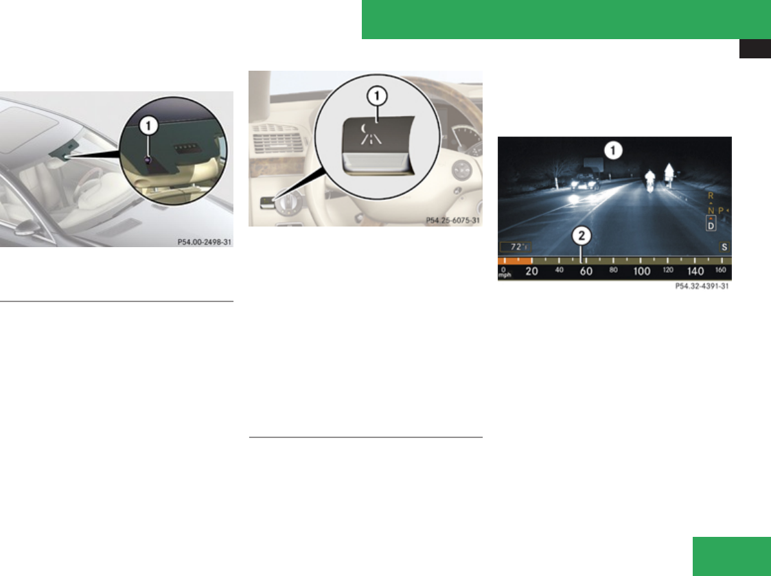
Driving systems
391
The camera is at the top of the windshield.
1Night View Assist camera
Switching on or off
You can only switch on the Night View Assist
if
Rthe SmartKey in the starter switch is set to
position 2
Rit is dark
Rthe light switch is set to * or B or if
the daytime driving lamps are switched on
Rthe automatic transmission is not in
reverse gear R
1Night View Assist on or off
XPress button 1 up or down.
The Night View Assist image appears on the
multifunction display.
iThe infrared headlamps only come on
above a speed of approximately 9 mph
(15 km/h). Therefore, when you are at a
standstill, you do not have a complete view
and cannot check the function of the Night
View Assist.
Image on multifunction display
When you switch on the Night View Assist, the
dial for the speedometer changes on the
multifunction display. The speedometer dial
is shown as a bar on the lower edge of the
multifunction display. The line for main
menus is no longer available. If you would like
to change a setting using the steering wheel
buttons, you must first switch off the Night
View Assist.
1Night View Assist image
2Speedometer dial
If you change the brightness of the
instrument cluster while the Night View
Assist is switched on, only the brightness of
the multifunction display is changed.
Controls in detail
Z

Driving systems
392
Adjusting instrument cluster illumination
1Knob
XMake sure the Night View Assist is
switched on.
XBrightening illumination: Turn knob 1
clockwise.
XDimming illumination: Turn knob 1
counterclockwise.
Dirty or fogged-up windshield
If the windshield in front of the camera is
fogged up on the inside or outside or if it is
dirty, the Night View Assist image is
diminished.
GWarning!
Please do not forget that your primary
responsibility is to drive the vehicle. A
driver’s attention to the road must always
be his/her primary focus when driving. For
your safety and the safety of others, stop
before trying to remove window fogging or
cleaning the window in front of the Night
View Assist camera.
Bear in mind that at a speed of just 30 mph
(approximately 50 km/h), your vehicle is
covering a distance of 44 feet
(approximately 14 m) every second.
XRemoving condensation: Check settings
of the climate control and change them, if
necessary (Y page 395).
XSwing the camera cover downward
(Y page 487).
XCleaning inside of windshield: Use a soft,
non-scratching cloth (Y page 487).
Blind Spot Assist
The Blind Spot Assist uses radar sensors to
monitor the area on both sides of your
vehicle. It will assist you when you change
lanes driving at speeds of above 20 mph
(30 km/h). A warning will appear in the
exterior rear view mirror as soon as another
vehicle is detected in the area being
monitored. If you then activate the
corresponding turn signals to change lanes,
you will see and hear a collision warning. The
Blind Spot Assist operates using two sensors
in the front bumper and four sensors in the
rear bumper.
GWarning!
The Blind Spot Assist is only a driving aid
and may not detect all vehicles.
The Blind Spot Assist may not be able to
detect narrow vehicles such as
motorcycles or bicycles, or it may not
detect them until it is too late.
The monitoring function may be impaired if
your sensors are dirty, subject to heavy
spray, or if visibility is poor due to e.g. snow,
rain, or fog. This can result in vehicles not
being detected or being detected too late.
Controls in detail

Driving systems
393
Blind Spot Assist cannot detect road, traffic
and weather conditions.
It is the driver’s responsibility at all times to
be attentive to road, weather and traffic
conditions and to provide the steering,
braking and other driving inputs necessary
to retain control of the vehicle. Failure to do
so could result in recognizing dangers too
late, possibly resulting in an accident and
serious injury to yourself and others.
In order for the Blind Spot Assist to function,
the radar sensors must be switched on and
operational.
When traveling in Canada in a vehicle not
registered in Canada, you must switch off the
radar sensor system (Y page 253). Canadian
law does not permit the use of the radar
sensor system for vehicles from outside of
Canada. When you switch off the radar sensor
system, the following functions are
deactivated:
RBlind Spot Assist
RBAS Plus (Y page 70)
RPRE-SAFE® Brake (Y page 76)
RDISTRONIC Plus (Y page 360)
RPark Assist (Y page 379)
RAdvanced Parking Guidance (Y page 383)
iUSA only:
This device has been approved by the FCC
as a “Vehicular Radar System”. The radar
sensor is intended for use in an automotive
radar system only. Removal, tampering, or
altering of the device will void any
warranties, and is not permitted by the
FCC. Do not tamper with, alter, or use in
any non-approved way.
Any unauthorized modification to this
device could void the user’s authority to
operate the equipment.
iCanada only:
This device complies with RSS-210 of
Industry Canada. Operation is subject to
the following two conditions:
1. This device may not cause interference,
and
2. this device must accept any
interference received, including
interference that may cause undesired
operation of the device.
Removal, tampering, or altering of the
device will void any warranties, and is not
permitted. Do not tamper with, alter, or use
in any non-approved way.
Any unauthorized modification to this
device could void the user’s authority to
operate the equipment.
Sensor monitoring range
The Blind Spot Assist is able to monitor a
range up to 10 ft (3 m) to the rear and both
sides of the vehicle.
GWarning!
The Blind Spot Assist monitors certain
areas in the immediate vicinity of your
vehicle. Vehicles approaching and passing
at speeds that exceed the speed of your
vehicle significantly will not be detected.
There will be no warning display and no
audible warning.
When driving in a very wide lane, the
sensors may not be able to cover the entire
width of the neighboring lane. Vehicles
driving on the outside of the neighboring
lane may not be detected.
Controls in detail
Z

Driving systems
394
It is the driver’s responsibility at all times to
be attentive to road, weather and traffic
conditions and to provide the steering,
braking and other driving inputs necessary
to retain control of the vehicle. Failure to do
so could result in recognizing dangers too
late, possibly resulting in an accident and
serious injury to yourself and others.
When driving in a very narrow lane, the
sensors may detect and display vehicles in
the second lane over. This will be the case
if there are vehicles driving on the inside
edge of their lane.
The Blind Spot Assist sensors are built into
the front and rear bumpers. Make sure that
the area of the bumpers around the sensors
is free of dirt, ice and snow. The radar sensors
must not be obstructed, for example, by
bicycle carriers or overhanging luggage.
! In the event of a significant impact or
damage affecting the bumpers, have the
radar sensors checked by a qualified
specialist workshop such as a Mercedes-
Benz Center. Failure to do this can result in
Blind Spot Assist not functioning correctly.
Indicator and warning lamps
Exterior rear view mirror, driver’s side
1Yellow indicator lamp/red warning lamp
XMake sure that the radar sensors
(Y page 253) and Blind Spot Assist
(Y page 251) are switched on.
XSwitch on the ignition.
Red warning lamps 1 in the exterior rear
view mirrors come on.
XStart the engine.
Yellow indicator lamps 1 in the exterior
rear view mirrors come on up to a speed of
20 mph (30 km/h).
Above a speed of 20 mph (30 km/h), yellow
indicator lamps 1 go out and the Blind Spot
Assist is active. If the Blind Spot Assist
detects a vehicle in its range, red warning
lamp 1 on the corresponding side of the
vehicle comes on.
When you shift the automatic transmission in
reverse gear R, yellow indicator lamps 1 in
the exterior rear view mirrors goes out after
approximately 3 seconds. The Blind Spot
Assist is then not active.
The brightness of indicator lamps/warning
lamps 1 is controlled automatically
depending on the brightness of the ambient
light.
GWarning!
The Blind Spot Assist is not active at speeds
below approximately 20 mph (30 km/h).
The yellow indicator lamps in the exterior
rear view mirrors are illuminated. You will
not be alerted to the presence of vehicles
in the monitored area at these speeds.
It is the driver’s responsibility at all times to
be attentive to road, weather and traffic
conditions and to provide the steering,
braking and other driving inputs necessary
to retain control of the vehicle. Failure to do
so could result in recognizing dangers too
late, possibly resulting in an accident and
serious injury to yourself and others.
Collision warning
If a vehicle is detected in the Blind Spot Assist
range and you activate the turn signal, a two-
tone warning will sound once and red warning
lamp 1 on the corresponding side of the
vehicle will flash.
Controls in detail
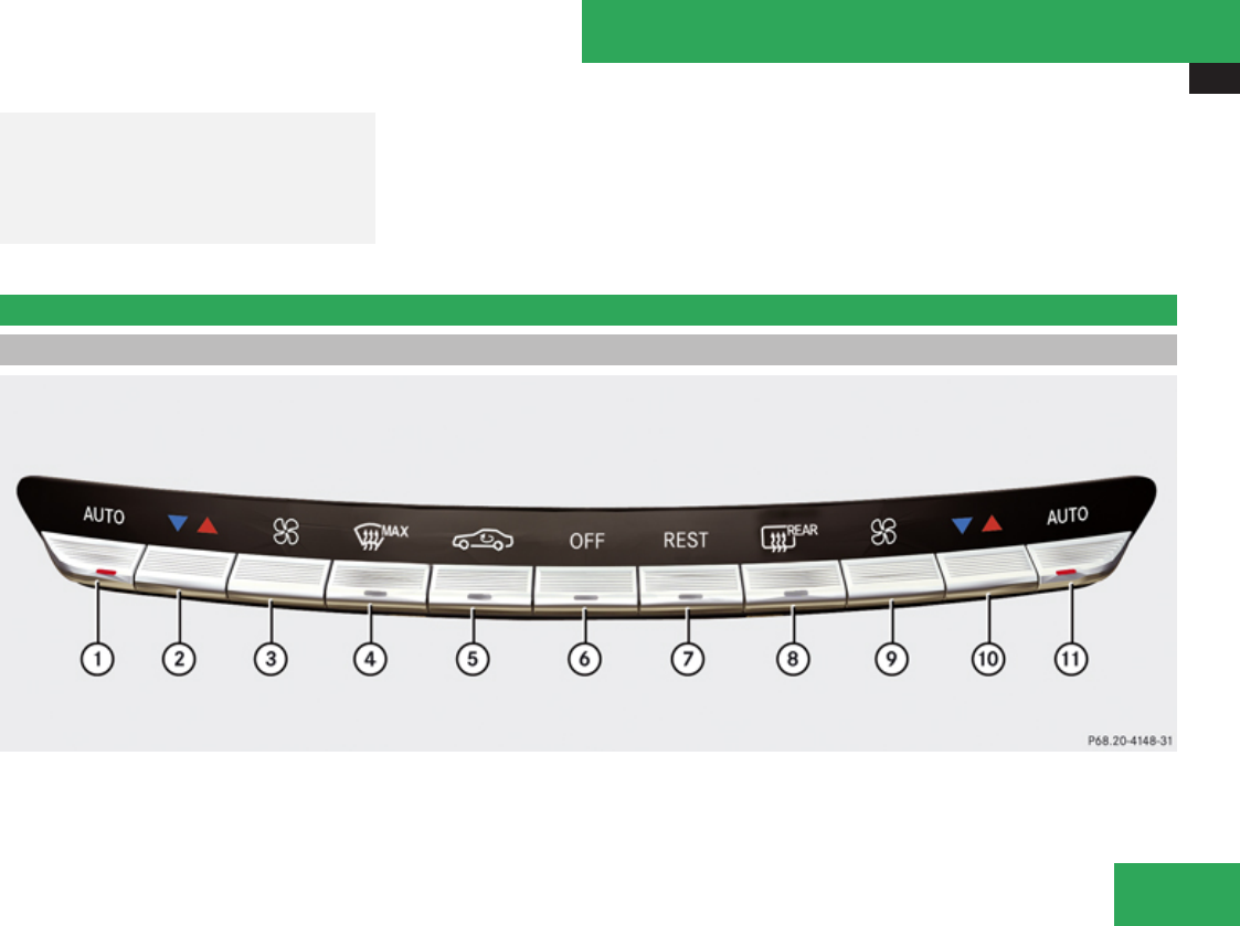
Climate control system
395
GWarning!
Do not change lanes or make turns, while
red warning lamp 1 is flashing. Doing so
could result in an accident and seroius
injury to yourself and others.
XRemain on the lane that you are currently
on until traffic conditions permit to change.
If the turn signal remains on, red warning
lamp 1 will flash to indicate that vehicles
have been detected. No further audible
warnings will sound.
Climate control system
Control panels
Controls in detail
Z

Climate control system
396
Function Recommendation/Notes
1U Air distribution and air volume, driver’s side
(automatic mode)
iSwitches on the automatic mode. The indicator
lamp in button U comes on.
(Y page 399)
2® Temperature control, driver’s side iSet the temperature to 72‡ (22†). (Y page 400)
3Q Manual fan speed adjustment, driver’s side (Y page 403)
4y Front defroster iKeep this setting selected only until the windshield
or the side windows are clear again.
(Y page 403)
5, Air recirculation iOnly use this function for a short time, e.g. in a
tunnel. Otherwise, the windows can fog up due to lack
of fresh air.
(Y page 404)
6´ Climate control on/off iSwitches on the climate control system. The
indicator lamp in button ´ goes out.
(Y page 398)
7T Residual heat/ventilation iWith the engine turned off, it is possible to continue
to heat or ventilate the interior.
(Y page 405)
8¯ Rear window defroster iAt very low temperatures, rear window defroster
operation is delayed until the vehicle interior has
warmed up.
(Y page 406)
9Q Manual fan speed adjustment, passenger side (Y page 403)
a® Temperature control, passenger side iSet the temperature to 72‡ (22†). (Y page 400)
bU Air distribution and air volume, passenger side
(automatic mode)
iSwitches on the automatic mode. The indicator
lamp in button U comes on.
(Y page 399)
Controls in detail
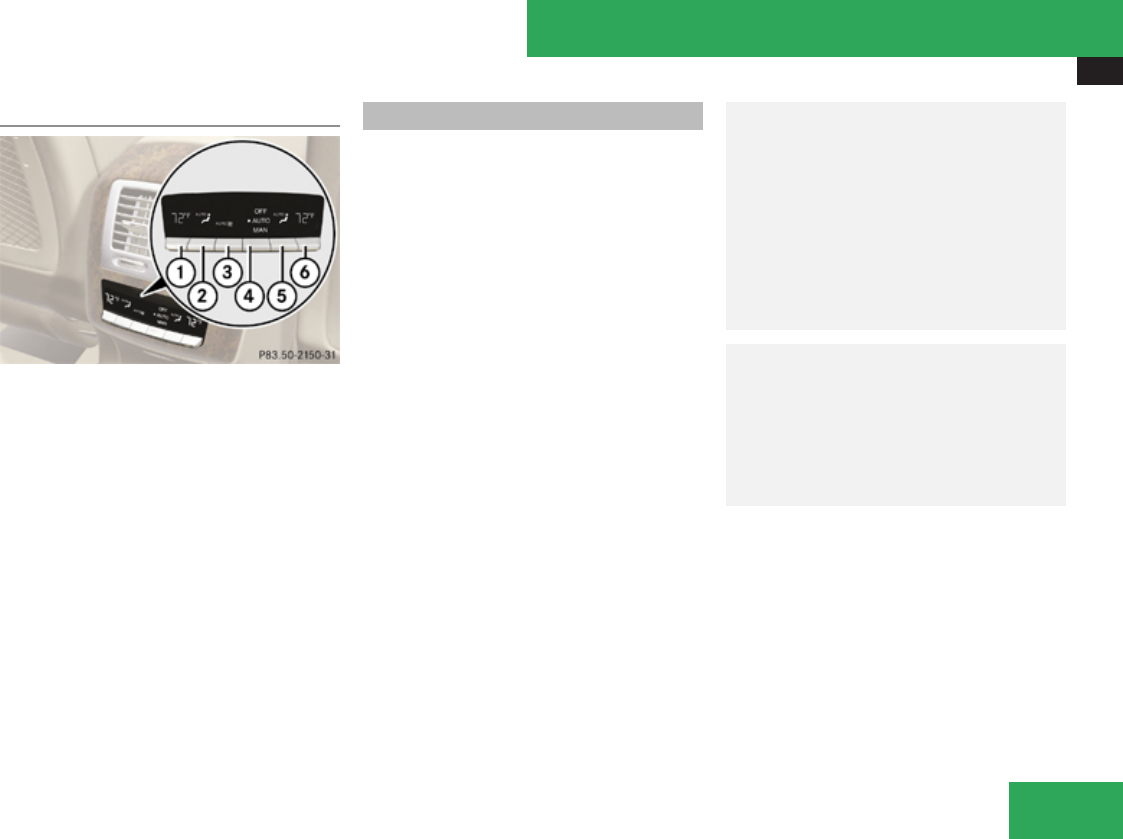
Climate control system
397
Rear climate control
1Temperature control, left
2Air distribution, left
3Air volume
4OFF Rear climate control on/off
AUTO Rear climate control automatic
mode
MAN Rear climate control manual mode
5Air distribution, right
6Temperature control, right
Notes on climate control system
iIf you have the air distribution and air
volume automatically controlled, you can
adjust the temperature, footwell
temperature and air flow. The following
basic settings are recommended:
RAutomatic air distribution control
(Y page 399)
RTemperature: 72‡ (22†) (Y page 400)
RFootwell temperature: 0 (Y page 230)
RAir flow: focused (Y page 230)
The climate control system is operational
whenever the engine is running. You can
operate the climate control system in either
the automatic or manual mode. The system
cools or heats the interior depending on the
selected interior temperature and the current
outside temperature.
It can only function optimally when you are
driving with the windows, the tilt/sliding
sunroof or tilt/sliding panel closed.
Nearly all dust particles, pollutants and odors
are filtered out before outside air enters the
passenger compartment through the air
distribution system.
GWarning!
Severe conditions (e.g. strong air pollution)
may require replacement of the filter before
its scheduled replacement interval. A
clogged filter will reduce the air volume to
the interior and the windows could fog up,
impairing visibility and endangering you
and others. Have a clogged filter replaced
as soon as possible at an authorized
Mercedes-Benz Center.
GWarning!
Follow the recommended settings for
heating and cooling given on the following
pages and in the “COMAND automatic
climate control” section. Otherwise the
windows could fog up, impairing visibility
and endangering you and others.
XKeep the air intake grille in front of the
windshield free of snow and debris.
Do not obstruct air flow by placing objects on
the air flow-through exhaust slots below the
rear window.
iIf the vehicle interior is hot, ventilate the
interior before driving off, see “Summer
opening feature” (Y page 336). The climate
control will then adjust the interior
temperature to the set value much faster.
Controls in detail
Z

Climate control system
398
The following climate control functions can
be operated via COMAND:
RTemperature (Y page 227)
RAir distribution (Y page 228)
RAir volume (Y page 228)
RSwitching off cooling (+) (Y page 229)
RCentral climate control (Mono)
(Y page 230)
RFootwell temperature (Y page 230)
RAir flow from air vents (Y page 230)
RRear climate control (Y page 231)
Deactivating the climate control
system
GWarning!
When the climate control system is
switched off, the outside air supply and
circulation are also switched off. Only
choose this setting for a short time.
Otherwise the windows could fog up,
impairing visibility and endangering you
and others.
Deactivating the front climate control
XDeactivating: Press rocker switch ´ up
or down.
The indicator lamp in the rocker switch
comes on. You will see Climate Control
OFF in the COMAND display.
XReactivating: Press rocker switch ´ up
or down.
The indicator lamp in the rocker switch
goes out. You will see the previous settings
in the COMAND display.
Deactivating the rear climate control
Operating on the front climate control
panel
XActivate the Rear) function via
COMAND (Y page 231). This function is
used to operate the rear climate control via
COMAND and the rocker switches on the
control panel from the front.
XDeactivating: Press rocker switch ´ up
or down.
The indicator lamp in the rocker switch
comes on.
XReactivating: Press rocker switch ´ up
or down.
The indicator lamp in the rocker switch
goes out. The previous settings are once
again in effect.
Operating on the rear climate control
panel
XDeactivating: Press rocker switch 4
(Y page 397) up or down repeatedly until
OFF mode is selected in display.
XReactivating: Press rocker switch 4 up or
down repeatedly until AUTO mode is
selected in display.
or
XPress rocker switch 4 up or down
repeatedly until MAN mode is selected in
display.
Controls in detail

Climate control system
399
Air conditioning
The air conditioning is operational while the
engine is running and cools the interior air to
the temperature set by the operator. In
addition, the air conditioning dehumidifies
the interior air and helps prevent window
fogging.
GWarning!
If you switch off the cooling function, the
vehicle will not be cooled when weather
conditions are warm. The windows can fog
up more quickly. Window fogging may
impair visibility and endanger you and
others.
iCondensation may drip out from
underneath the vehicle. This is normal and
not an indication of a malfunction.
The cooling function can be activated or
deactivated via COMAND (Y page 229).
Automatic mode
Air distribution and air volume can be
adjusted automatically by the climate control
system. You can also adjust the settings for
air distribution and air volume manually.
When operating the climate control system in
automatic mode, the interior air temperature,
air volume and air distribution are adjusted
automatically.
In automatic mode, cooling with
dehumidification is switched on. This function
can be switched off if necessary.
GWarning!
If you switch off the cooling function, the
vehicle will not be cooled when weather
conditions are warm. The windows can fog
up more quickly. Window fogging may
impair visibility and endanger you and
others.
Automatic mode with the front climate
control
XSet the desired temperature
(Y page 400).
XActivating: Press rocker switch U up or
down.
The indicator lamp in the rocker switch
comes on.
XDeactivating: Press rocker switch U up
or down.
or
XPress rocker switch Q up or down.
or
XAdjust air volume via COMAND
(Y page 228).
The indicator lamp in rocker switch U
goes out.
Automatic mode with the rear climate
control
Operating on the front climate control
panel
XSet the desired temperature
(Y page 400).
XActivate the Rear) function via
COMAND (Y page 231). This function is
used to operate the rear climate control via
COMAND and the rocker switches on the
control panel from the front.
XActivating: Press rocker switch U up or
down.
The indicator lamp in the rocker switch
comes on.
XDeactivating: Press rocker switch U up
or down.
Controls in detail
Z
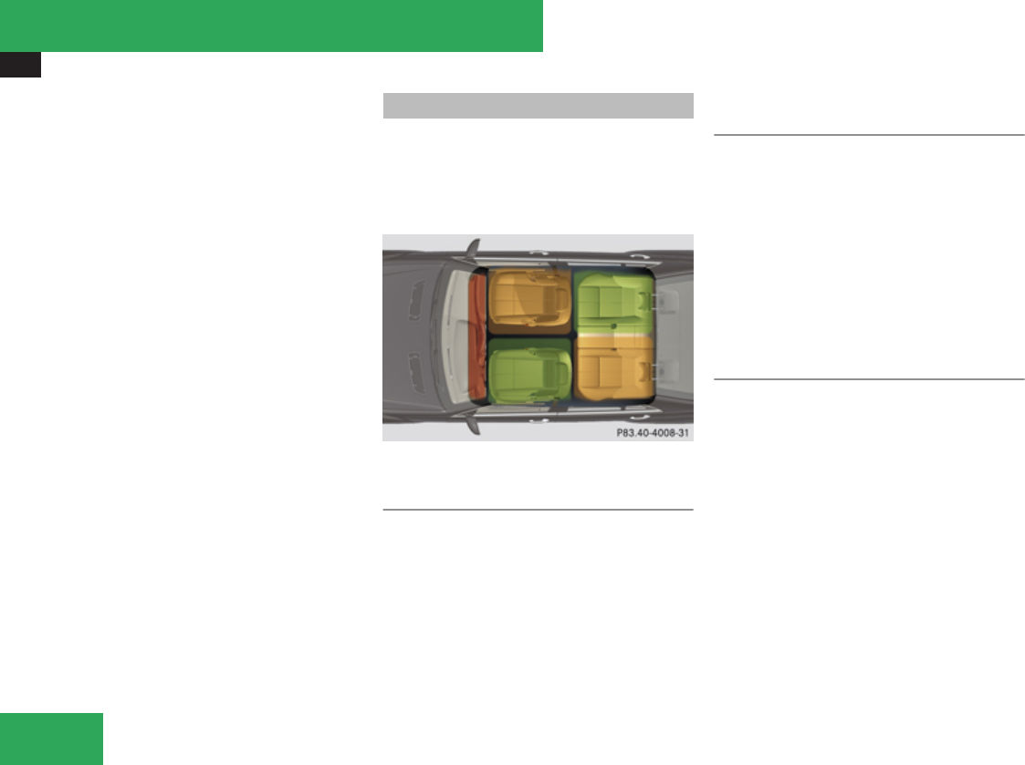
Climate control system
400
or
XAdjust air distribution (Y page 228).
or
XAdjust air volume (Y page 228).
The indicator lamp in rocker switch U
goes out. Automatic control of air volume
and air distribution is switched off.
You can adjust the air distribution
(Y page 228) or air volume (Y page 228)
manually.
iTo return to the standard display, activate
the Front Climate Control function via
COMAND (Y page 232).
Operating on the rear climate control
panel
XSet the desired temperature
(Y page 400).
XActivating: Press rocker switch 4
(Y page 397) repeatedly until AUTO mode is
selected in the display.
XDeactivating: Press rocker switch 4
repeatedly until MAN mode or OFF mode is
selected in the display.
Setting temperature
You can adjust the air temperature for each
of the 5 zones separately. You should raise or
lower the temperature setting in small
increments, preferably starting at 72‡
(22†).
Front temperature with front climate
control panel
XIncreasing/decreasing: Press rocker
switches ® 2 and/or a up or down or
use COMAND (Y page 227).
The climate control system will
correspondingly adjust the interior air
temperature.
Rear temperature with front climate
control panel
XActivate the Rear) function via
COMAND (Y page 231). This function is
used to operate the rear climate control via
COMAND and the rocker switches on the
control panel from the front.
XIncreasing/decreasing: Press rocker
switches ® 2 and/or a
(Y page 395) up or down.
Rear temperature with rear climate
control panel
XIncreasing/decreasing: Press rocker
switches ® 1 and/or 6
(Y page 397) up or down.
Controls in detail
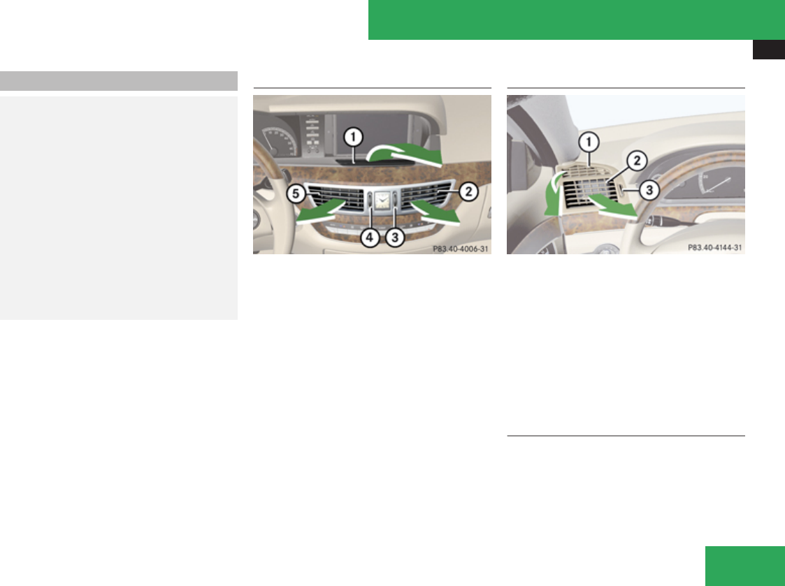
Climate control system
401
Adjusting air vents
GWarning!
When operating the climate control, the air
that enters the passenger compartment
through the air vents can be very hot or very
cold (depending on the set temperature).
This may cause burns or frostbite to
unprotected skin in the immediate area of
the air vents.
Always keep sufficient distance between
unprotected parts of the body and the air
vents. If necessary, use the air distribution
adjustment to direct the air to air vents in
the vehicle interior that are not in the
immediate area of unprotected skin.
For best possible performance of the climate
control:
XKeep the air intake grille in front of the
windshield free of snow, leaves, sticks, and
any other debris.
XAlways keep all air vents and grilles in the
passenger compartment free from
obstruction.
iFor draft-free ventilation, move the
adjustable center and side air vents to the
middle position.
Center air vents
1Cockpit air vent, fixed
2Right center air vent, adjustable
3Thumbwheel for air volume control for
adjustable right center air vent
4Thumbwheel for air volume control for
adjustable left center air vent
5Left center air vent, adjustable
XOpening/closing: Turn thumbwheels 3
and 4 upward or downward.
Side air vents
Example illustration driver’s side
1Left side defroster air vent, fixed
2Left side air vent, adjustable
3Thumbwheel for air volume control for
adjustable left side air vent
XOpening/closing: Turn thumbwheel 3
upward or downward.
Front center console storage
compartment ventilation
In vehicles without rear passenger
compartment climate control: the storage
compartment under the front armrest can be
ventilated when the climate control is
switched on.
Controls in detail
Z
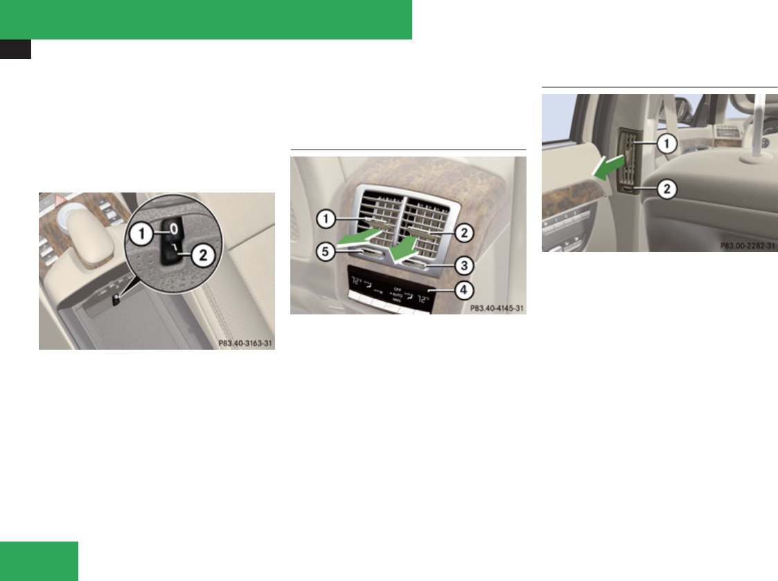
Climate control system
402
! Extreme temperatures can occur in the
storage compartment. Switch off the air
vents in the storage compartment while the
heating is switched on if you are
transporting heat-sensitive items in the
compartment.
Keep the air vents free of obstruction.
1Switching ventilation off
2Switching ventilation on
The air volume is dependent on the setting of:
Rair distribution control
Rair volume control
Rair vents in the dashboard
The air temperature is about the same as that
of the dashboard air vents. It cannot be
regulated separately.
Rear center console air vents
1Left rear center air vent, adjustable
2Right rear center air vent, adjustable
3Thumbwheel for air volume control for
right rear center air vent
4Rear climate control panel
5Thumbwheel for air volume control for left
rear center air vent
XOpening/closing: Turn thumbwheel 3 or
5 in the required direction.
B-pillar air vents
1Side air vent, adjustable
2Thumbwheel for air volume control for
side air vent
XOpening/closing: Turn thumbwheel 2 to
the left or to the right.
Controls in detail

Climate control system
403
Adjusting air distribution
Air distribution in front/rear passenger
compartment via COMAND
The air distribution can be adjusted via
COMAND (Y page 228).
Air distribution in rear passenger
compartment with rear climate control
panel
XPress rocker switches 2 or 5
(Y page 397) up or down until the desired
symbol appears in the display.
Adjusting air volume
You can adjust the air volume separately on
each side if the passenger compartment.
You can adjust the air volume via COMAND
(Y page 228).
Front air volume with the front climate
control panel
XDecrease/increase: Press rocker
switches Q up or down.
Rear air volume with the front climate
control panel
XActivate the Rear) function via
COMAND (Y page 231). This function is
used to operate the rear climate control via
COMAND and the rocker switches on the
control panel from the front.
XDecrease/increase: Press rocker
switches Q up or down.
Rear air volume with the rear climate
control panel
XDecrease/increase: Press rocker switch
3 (Y page 397) up or down.
Front defroster
You can use this setting to defrost the
windshield, for example if it is iced up.
You can also defog the windshield and the
side windows.
iKeep this setting selected only until the
windshield or the side windows are clear
again.
Activating
XPress rocker switch y up or down.
The indicator lamp in the rocker switch
comes on.
The climate control switches to the following
functions automatically:
Rmost efficient blower speed and heating
power, depending on outside temperature
Rair flows onto the windshield and the front
side windows
Rthe air conditioning compressor switches
on at outside temperatures above
approximately 41‡ (5†) for air-drying
Adjustments
You can adjust the air volume and the
temperature when the front defroster is
switched on. The air flow will remain on the
windshield and front door windows.
XPress rocker switch Q up or down to
increase or decrease air volume to the
desired level.
The air volume increases/decreases to the
next higher/lower blower speed and
heating switches to the temperature that
was set before the front defroster was
switched on.
Controls in detail
Z

Climate control system
404
The indicator lamp in rocker switch y
goes out.
or
XPress rocker switches ® 2 and a
(Y page 395) up or down.
Heating switches to the temperature that
was set before the front defroster was
switched on.
The indicator lamp in rocker switch y
goes out.
iThe air conditioning compressor remains
on even with the indicator lamp in button
y goes out. This helps to prevent
windshield from fogging.
Deactivating
XPress rocker switch y up or down.
The indicator lamp in the rocker switch
goes out.
The previous settings are once again in
effect, except air recirculation mode stays
off.
Windshield fogged on the outside
XSwitch the windshield wipers on
(Y page 332).
XPress rocker switch U up or down.
The indicator lamp in the rocker switch
comes on.
Maximum cooling MAX COOL
MAX COOL is only operational when the
engine is running.
MAX COOL is only available in U.S. vehicles.
If U is selected on both the left and right
side and there is a high demand for cooling,
the display MAXCOOL appears in the COMAND
display.
This provides the fastest possible cooling of
the vehicle interior (when windows and tilt/
sliding sunroof or tilt/sliding panel are
closed).
iMaximum cooling MAX COOL is only
available when the engine is running.
Air recirculation mode
Switch to air recirculation mode to prevent
unpleasant odors from entering the vehicle
from the outside (e. g. before driving through
a tunnel). This setting cuts off the intake of
outside air and recirculates the air in the
passenger compartment.
GWarning!
Fogged windows impair visibility,
endangering you and others. If the windows
begin to fog on the inside, switching off the
air recirculation mode immediately should
clear interior window fogging. If interior
window fogging persists, make sure the air
conditioning is activated, or press button
y.
XActivating: Press rocker switch , up or
down.
The indicator lamp in the rocker switch
comes on.
iThe air recirculation mode is activated
automatically at high outside
temperatures.
The indicator lamp in rocker switch , is
not lit when the air recirculation mode is
switched on automatically.
Controls in detail

Climate control system
405
A quantity of outside air is added when the
cooling demand is not at maximum.
If the air conditioning has been turned off
or the outside temperature is below 41‡
(5†), the air recirculation mode will not
switch on automatically.
XDeactivating: Press rocker switch , up
or down.
The indicator lamp in the rocker switch
goes out.
iThe manually selected air recirculation
mode is deactivated automatically:
Rafter 5 minutes if the outside
temperature is below approximately
41‡ (5†)
Rafter 5 minutes if the air conditioning is
turned off
Rafter 30 minutes if the outside
temperature is above approximately
41‡ (5†)
Residual heat and ventilation
With the engine switched off, it is possible to
continue to heat or ventilate the interior for
up to 30 minutes. This feature makes use of
the residual heat produced by the engine.
iIf you switch on the residual heat function
when outside temperatures are high, only
the ventilation will be switched on.
iRegardless of the selected air volume, the
blower operates at low speed when
heating. In case of ventilation the blower
operates at higher speed.
iHow long the system will provide heating
depends on the coolant temperature and
the selected temperature. The blower will
run at low speed regardless of the air
distribution control setting.
XActivating: Switch off the ignition.
XPress rocker switch T up or down.
The indicator lamp in the rocker switch
comes on.
XDeactivating: Press rocker switch T up
or down.
The indicator lamp in the rocker switch
goes out.
The residual heat is deactivated
automatically:
Rwhen the ignition is switched on
Rafter approximately 30 minutes
Rif the battery voltage drops
Rif the coolant temperature is too low
Controls in detail
Z

Power tilt/sliding sunroof
406
Rear window defroster
GWarning!
Any accumulation of snow and ice should
be removed from the rear window before
driving. Visibility could otherwise be
impaired, endangering you and others.
The rear window defroster uses a large
amount of power. To keep the battery drain
to a minimum, switch off the defroster as
soon as the rear window is clear. The
defroster is switched off automatically after
approximately 6 to 17 minutes of operation
depending on the outside temperature.
XSwitch on the ignition.
XSwitching on: Press button ¯ up or
down.
The indicator lamp in the button comes on.
XSwitching off: Press button ¯ up or
down.
! If the rear window defroster switches off
too soon and the indicator lamp starts
flashing, too many electrical consumers
are operating simultaneously and there is
insufficient voltage in the battery. The
system responds automatically by
switching the rear window defroster off.
As soon as the battery has sufficient
voltage, the rear window defroster
switches back on automatically.
Power tilt/sliding sunroof
Opening and closing
GWarning!
When opening or closing the tilt/sliding
sunroof, make sure there is no danger of
anyone being harmed by the opening/
closing procedure.
The tilt/sliding sunroof is equipped with the
express operation and automatic reversal
function. If the movement of the tilt/sliding
sunroof is blocked during the closing
procedure, the tilt/sliding sunroof will stop
and open slightly.
The tilt/sliding sunroof operates differently
when the sunroof switch is pressed and
held. See the “Closing when the tilt/sliding
sunroof is blocked” section for details.
The opening/closing procedure of the tilt/
sliding sunroof can be immediately halted
by releasing the sunroof switch or, if the
sunroof switch was moved past the
resistance point and released, by moving
the sunroof switch in any direction.
Controls in detail
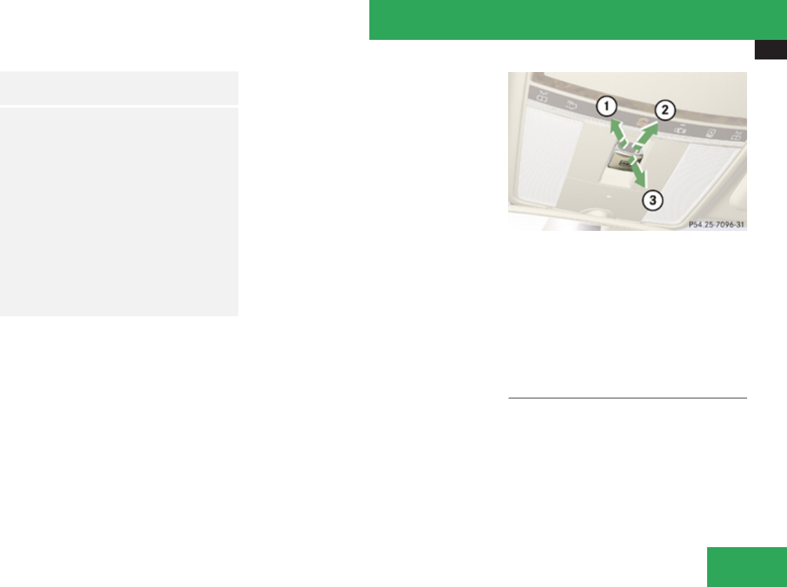
Power tilt/sliding sunroof
407
GObserve Safety notes, see
page 62.
GWarning!
The tilt/sliding sunroof is made out of
glass. In the event of an accident, the glass
may shatter. This may result in an opening
in the roof.
In a vehicle rollover, occupants not wearing
their seat belts or not wearing them
properly may be thrown out of the opening.
Such an opening also presents a potential
for injury for occupants wearing their seat
belts properly as entire body parts or
portions of them may protrude from the
passenger compartment.
! To avoid damaging the seals, do not
transport any objects with sharp edges
which can stick out of the tilt/sliding
sunroof.
Do not open the tilt/sliding sunroof if there
is snow or ice on the roof, as this could
result in malfunctions.
If you cannot open or close the tilt/sliding
sunroof due to a malfunction contact
Roadside Assistance or an authorized
Mercedes-Benz Center.
! Please keep in mind that weather
conditions can sometimes change rapidly.
Make sure to close the tilt/sliding sunroof
when leaving the vehicle. If water enters
the vehicle interior, vehicle electronics
could be damaged which is not covered by
the Mercedes-Benz Limited Warranty.
iYou can also open or close the tilt/sliding
sunroof using the SmartKey or the
KEYLESS-GO function, see “Summer
opening feature” (Y page 336) and
“Convenience closing
feature” (Y page 337).
iAfter switching off the ignition or
removing the SmartKey from the starter
switch, you can operate the tilt/sliding
sunroof until you open the driver’s or front
passenger door. If no door was opened you
can operate the tilt/sliding sunroof for up
to 5 minutes.
Sunroof switch
1Raising
2Opening
3Closing
With the sunroof closed or raised, you can
slide the sunroof screen forward and back.
XSwitch on the ignition.
Opening
XOpening manually: Press and hold the
sunroof switch to the resistance point in
direction of arrow 2.
XRelease the sunroof switch when the
desired position is reached.
XExpress operation: To open the tilt/
sliding sunroof completely, press the
Controls in detail
Z

Power tilt/sliding sunroof
408
sunroof switch past the resistance point in
direction of arrow 2 and release.
XStopping during express operation:
Move the sunroof switch in any direction.
iExpress opening is not available when the
tilt/sliding sunroof is raised. The tilt/
sliding sunroof must be closed first.
iWhen the tilt/sliding sunroof is open,
resonance noises may result in addition to
the usual wind noises. They are caused by
minimal pressure changes in the passenger
compartment. To reduce or eliminate these
noises, change the position of the tilt/
sliding sunroof or open a window slightly.
Raising
XRaising manually: Press and hold the
sunroof switch to the resistance point in
direction of arrow 1.
XRelease the sunroof switch when the
desired position is reached.
XExpress operation: To raise the tilt/
sliding sunroof completely, press the
sunroof switch past the resistance point in
direction of arrow 1 and release.
XStopping during express operation:
Move the sunroof switch in any direction.
iExpress raising is not available when the
tilt/sliding sunroof is open. The tilt/sliding
sunroof must be closed first.
Closing
XClosing manually: Pull and hold the
sunroof switch to the resistance point in
direction of arrow 3.
XRelease the sunroof switch when the
desired position is reached.
XExpress operation: To close the tilt/
sliding sunroof completely, pull the sunroof
switch past the resistance point in
direction of arrow 3 and release.
XStopping during express operation:
Move the sunroof switch in any direction.
Closing when the tilt/sliding sunroof is
blocked
GWarning!
Make sure that nobody can become
trapped and be seriously or even fatally
injured when closing the tilt/sliding
sunroof with greater force or without
automatic reversal function.
If the movement of the tilt/sliding sunroof is
blocked during the closing procedure (e. g. by
ice or pollution), the tilt/sliding sunroof will
stop and open slightly. However, the tilt/
sliding sunroof will exert greater force before
reversing than when the tilt/sliding sunroof
is closed in express operation. Please
exercise caution!
XImmediately after the tilt/sliding sunroof
has stopped because it was blocked, pull
the sunroof switch in direction of arrow
3 until the tilt/sliding sunroof is fully
closed.
If the tilt/sliding sunroof is blocked again and
opens slightly:
XImmediately after the tilt/sliding sunroof
was blocked, pull the sunroof switch in
direction of arrow 3 until the tilt/sliding
sunroof is fully closed.
GWarning!
Pulling and holding the sunroof switch to
close the tilt/sliding sunroof immediately
after it had been blocked two times will
cause the tilt/sliding sunroof to close
without any reversal function for as long as
you hold the sunroof switch.
Controls in detail

Panorama roof with power tilt/sliding panel
409
Synchronizing
The tilt/sliding sunroof must be synchronized
after a malfunction or if it does not open
smoothly.
! If the tilt/sliding sunroof cannot be closed
or synchronized, contact an authorized
Mercedes-Benz Center or call Roadside
Assistance.
XSwitch on the ignition.
XPress and hold the sunroof switch in
direction of arrow 1 (Y page 407) until the
tilt/sliding sunroof is fully raised at the
rear.
XKeep holding the sunroof switch in
direction of arrow 1 for approximately
1 second.
XCheck the express operation feature
(Y page 407).
If the tilt/sliding sunroof opens and closes
completely, the roof is synchronized.
Otherwise repeat the above steps.
Panorama roof with power tilt/sliding
panel
Extending and retracting the roller
sunblinds
The roller sunblinds only operate with the tilt/
sliding panel closed. The front and rear roller
sunblind can be operated individually.
XSwitch on the ignition.
Operating front roller sunblind
GWarning!
When extending the front roller sunblind,
make sure no one is in danger of being
injured by the extending procedure.
The front roller sunblind is equipped with
the express operation and automatic
reversal function. If the movement of the
front roller sunblind is blocked during the
extending procedure, the front roller
sunblind will stop and retract slightly.
The extending of the front roller sunblind
can be immediately halted by releasing the
roof panel switch or, if the roof panel switch
was moved past the resistance point and
released, by moving the roof panel switch
in any direction.
Roof panel switch
1Retracting
2Retracting
3Extending
XRetracting/Extending: Move the roof
panel switch to the resistance point in the
required direction of arrow 1, 2 or 3
until the front roller sunblind has reached
its desired position.
XExpress operation: Move the roof panel
switch past the resistance point in
direction of arrow 1, 2 or 3 and release.
The front roller sunblind retracts/extends
completely.
XStopping during express operation:
Move the roof panel switch in any direction.
Controls in detail
Z
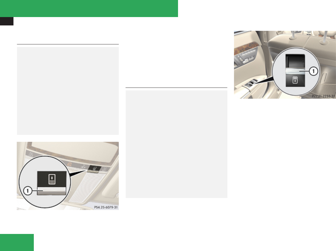
Panorama roof with power tilt/sliding panel
410
Operating rear roller sunblind from
front
GWarning!
When extending the rear roller sunblind,
make sure no one is in danger of being
injured by the extending procedure.
The rear roller sunblind is equipped with the
express operation and automatic reversal
function. If the movement of the rear roller
sunblind is blocked during the extending
procedure, the rear roller sunblind will stop
and retract slightly.
The extending of the rear roller sunblind
can be immediately halted by pressing the
sunblind switch again.
1Roller sunblind switch
XRetracting/Extending: Press switch 1.
The rear roller sunblind retracts/extends
completely.
XStopping: Press switch 1 again.
To change directions, you must first extend
or retract the rear roller sunblind completely.
Operating rear roller sunblind from rear
GWarning!
When extending the rear roller sunblind,
make sure no one is in danger of being
injured by the extending procedure.
The rear roller sunblind is equipped with the
express operation and automatic reversal
function. If the movement of the rear roller
sunblind is blocked during the extending
procedure, the rear roller sunblind will stop
and retract slightly.
The extending of the rear roller sunblind
can be immediately halted by releasing the
sunblind switch or, if the sunblind switch
was moved past the resistance point and
released, by pressing or pulling the
sunblind switch again.
Rear door control panel
1Roller sunblind switch
XRetracting/Extending: Press or pull
switch 1 until the rear roller sunblind has
reached the desired position.
XExpress operation: Press or pull switch
1 past the resistance point and release.
The rear roller sunblind retracts or extends
completely.
XStopping during express operation:
Press or pull switch 1 again.
Controls in detail
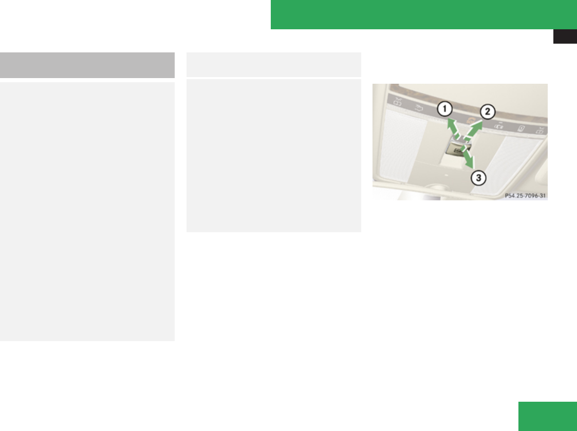
Panorama roof with power tilt/sliding panel
411
Opening and closing the panorama
roof with power tilt/sliding panel
GWarning!
When opening or closing the tilt/sliding
panel, make sure there is no danger of
anyone being harmed by the opening/
closing procedure.
The tilt/sliding panel is equipped with the
express operation and automatic reversal
function. If the movement of the tilt/sliding
panel is blocked during the closing
procedure, the tilt/sliding panel will stop
and open slightly.
The tilt/sliding panel operates differently
when the roof panel switch is pressed and
held. See the “Closing when the tilt/sliding
panel is blocked” section in this chapter for
details.
The opening/closing procedure of the tilt/
sliding panel can be immediately halted by
releasing the roof panel switch or, if the roof
panel switch was moved past the
resistance point and released, by moving
the roof panel switch in any direction.
GObserve Safety notes, see
page 62.
GWarning!
The panorama roof with tilt/sliding panel is
made out of glass. In the event of an
accident, the glass may shatter. This may
result in an opening in the roof.
In a vehicle rollover, occupants not wearing
their seat belts or not wearing them
properly may be thrown out of the opening.
Such an opening also presents a potential
for injury for occupants wearing their seat
belts properly as entire body parts or
portions of them may protrude from the
passenger compartment.
! To avoid damaging the seals, do not
transport any objects with sharp edges
which can stick out of the tilt/sliding panel.
Do not open the tilt/sliding panel if there is
snow or ice on the roof, as this could result
in malfunctions.
! Please keep in mind that weather
conditions can sometimes change rapidly.
Make sure to close the tilt/sliding panel
when leaving the vehicle. If water enters
the vehicle interior, vehicle electronics
could be damaged which is not covered by
the Mercedes-Benz Limited Warranty.
Roof panel switch
1Raising
2Opening
3Closing
The tilt/sliding panel only operates with the
roller sunblinds retracted.
iYou can also open or close the tilt/sliding
panel using the SmartKey, see “Summer
opening feature” (Y page 336) or see
“Convenience closing
feature” (Y page 337).
iIf the front roller sunblind is extended
while the tilt/sliding panel is being raised,
the roller sunblind will retract first.
Controls in detail
Z

Panorama roof with power tilt/sliding panel
412
XSwitch on the ignition.
Opening
XOpening manually: Press and hold the
roof panel switch to the resistance point in
direction of arrow 2.
XRelease the roof panel switch when the
desired position is reached.
XExpress operation: To open the tilt/
sliding panel completely, press the roof
panel switch past the resistance point in
direction of arrow 2 and release.
XStopping during express operation:
Move the roof panel switch in any direction.
iWhen the tilt/sliding panel is open,
resonance noises may result in addition to
the usual wind noises. They are caused by
minimal pressure changes in the passenger
compartment. To reduce or eliminate these
noises, change the position of the tilt/
sliding panel or open a window slightly.
Raising
XRaising manually: Press and hold the roof
panel switch to the resistance point in
direction of arrow 1.
XRelease the roof panel switch when the
desired position is reached.
XExpress operation: To raise the tilt/
sliding panel completely, press the roof
panel switch past the resistance point in
direction of arrow 1 and release.
XStopping during express operation:
Move the roof panel switch in any direction.
iExpress raising is not available when the
tilt/sliding panel is open. The tilt/sliding
panel must be closed first.
Closing
XClosing manually: Pull and hold the roof
panel switch to the resistance point in
direction of arrow 3.
XRelease the roof panel switch when the
desired position is reached.
XExpress operation: To close the tilt/
sliding panel completely, pull the roof panel
switch past the resistance point in
direction of arrow 3 and release.
XStopping during express operation:
Move the roof panel switch in any direction.
Closing when the tilt/sliding panel is
blocked
GWarning!
Make sure that nobody can become
trapped and be seriously or even fatally
injured when closing the tilt/sliding panel
without automatic reversal function.
If the movement of the tilt/sliding panel is
blocked during the closing procedure (e. g. by
ice or pollution), the tilt/sliding panel will stop
and open slightly.
XImmediately after the tilt/sliding panel has
stopped because it was blocked, pull the
roof panel switch in direction of arrow 3
until the tilt/sliding panel is fully closed.
If the tilt/sliding panel is blocked again and
opens slightly:
XImmediately after the tilt/sliding panel was
blocked, pull the roof panel switch in
direction of arrow 3 until the tilt/sliding
panel is fully closed.
Controls in detail

Panorama roof with power tilt/sliding panel
413
GWarning!
Pulling and holding the roof panel switch to
close the tilt/sliding panel immediately
after it had been blocked two times will
cause the tilt/sliding panel to close without
any reversal function for as long as you hold
the roof panel switch.
Synchronizing
The tilt/sliding panel and front roller
sunblinds must be synchronized after a
malfunction or if the tilt/sliding panel does
not open smoothly.
! Do not attempt to open the tilt/sliding
panel before the tilt/sliding panel is
properly synchronized. The tilt/sliding
panel could otherwise lock-up in the open
position.
If the tilt/sliding panel cannot be closed or
synchronized, contact an authorized
Mercedes-Benz Center or call Roadside
Assistance.
Tilt/sliding panel and front roller
sunblind
XSwitch on the ignition.
XPull and hold the roof panel switch several
times in direction of arrow 3
(Y page 409) until the tilt/sliding panel is
fully closed.
XKeep holding the roof panel switch in
direction of arrow 3 for approximately
1 second.
XPull and hold the roof panel switch several
times in direction of arrow 3 until the front
roller sunblind is fully extended.
XKeep holding the roof panel switch in
direction of arrow 3 for approximately
1 second.
XCheck the express operation feature of the
front roller sunblind.
If the front roller sunblind retracts
completely, the front roller sunblind is
synchronized. Otherwise repeat the above
steps.
XCheck the express operation feature of the
tilt/sliding panel (Y page 411).
If the tilt/sliding panel opens completely,
the tilt/sliding panel is synchronized.
Otherwise repeat the above steps.
Rear roller sunblind
XSwitch on the ignition.
XPull switch 1 (Y page 410) in the rear door
control panel several times until the rear
roller sunblind is fully extended.
XKeep holding switch 1 for approximately
1 second.
XCheck the express operation feature of the
front roller sunblind.
If the rear roller sunblind retracts
completely, the rear roller sunblind is
synchronized. Otherwise repeat the above
steps.
Controls in detail
Z

Loading and storing
414
Loading and storing
Loading instructions
GWarning!
Always fasten items being carried as
securely as possible using cargo tie-down
hooks and fastening materials appropriate
for the weight and size of the load.
In an accident, during hard braking or
sudden maneuvers, loose items will be
thrown around inside the vehicle and can
cause injury to vehicle occupants unless
the items are securely fastened in the
vehicle.
To help avoid personal injury during a
collision or sudden maneuver, exercise
care when transporting cargo. Do not pile
luggage or cargo higher than the seat
backrests.
The trunk is the preferred place to carry
objects. Always use cargo tie-down hooks
when transporting cargo. Do not place
anything on the rear-window shelf.
Never drive vehicle with the trunk open.
Deadly carbon monoxide (CO) gases may
enter vehicle interior resulting in
unconsciousness and death.
Load distribution
The total load weight including vehicle
occupants and luggage/cargo should not
exceed the total load limit indicated on the
corresponding Tire and Loading Information
placard located on the driver’s door B-pillar
(Y page 453).
The handling characteristics of a fully loaded
vehicle depend greatly on the load
distribution. It is therefore recommended to
load the vehicle accordingly with the heaviest
items being placed towards the front of the
vehicle.
Please pay attention to and comply with the
following instructions when loading the
vehicle and transporting cargo:
RAlways place items being carried against
front or rear seat backrests, and fasten
them as securely as possible.
RThe heaviest portion of the cargo should
always be kept as low as possible against
front or rear seat backrests.
Roof rack
For information about further roof rack
equipment, contact an authorized Mercedes-
Benz Center.
GWarning!
Only use roof racks approved by Mercedes-
Benz for your vehicle model to avoid
damage to the vehicle.
Follow the manufacturer’s installation
instructions. Otherwise, an improperly
attached roof rack system or its load could
become detached from the vehicle.
Do not exceed the maximum roof load of
220 lb (100 kg).
Take into consideration that when the roof
rack is loaded, the handling characteristics
are different from those when operating the
vehicles without the roof rack loaded.
Make sure
Ryou can raise the tilt/sliding sunroof or the
panorama roof with tilt/sliding panel
completely
Ryou can open the trunk completely
Controls in detail

Loading and storing
415
1Trim cover
XFlip trim covers 1 open.
XOnly attach the roof rack to the anchorage
points under trim covers 1.
XObserve manufacturer’s instructions for
installation.
Parcel nets
GWarning!
The parcel net is intended for storing light-
weight items only, such as road maps, mail,
etc.
Heavy objects, objects with sharp edges or
fragile objects may not be transported in
the parcel net. In an accident, during hard
braking, or sudden maneuvers, they could
be thrown around inside the vehicle and
cause injury to vehicle occupants.
The parcel net cannot protect transported
goods in the event of an accident.
Parcel nets are located in the front passenger
footwell and on each side of the left and right
trunk side walls.
Storage compartments
GWarning!
To help avoid personal injury during a
collision or sudden maneuver, exercise
care when storing objects in the vehicle.
Put luggage or cargo in the trunk if possible.
Do not pile luggage or cargo higher than the
seat backrests.
Parcel nets cannot secure hard or heavy
objects.
Keep compartment lids closed. This will
help to prevent stored objects from being
thrown about and injuring vehicle
occupants during
Rbraking
Rvehicle maneuvers
Ran accident
Controls in detail
Z
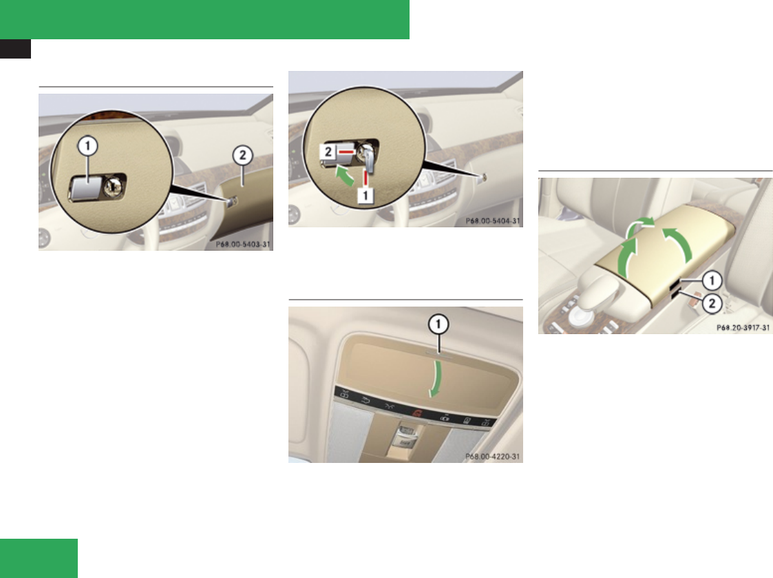
Loading and storing
416
Glove box
1Glove box lid release
2Glove box lid
XOpening: Press glove box lid release 1.
XClosing: Push glove box lid 2 up until it
engages.
Locking and unlocking the glove box
separately
You can lock the glove box separately, e.g.
when the vehicle is in the shop for service.
The glove box can only be locked or unlocked
with the mechanical key.
$Unlocking glove box
%Locking glove box
Eyeglasses compartment
1Eyeglasses compartment mark
XOpening: Press eyeglasses compartment
mark 1.
XClosing: Swing eyeglasses compartment
upward until it engages.
Front armrest storage compartments
1Button for storage tray/telephone
compartment
2Button for storage compartment
XOpening storage tray/telephone
compartment: Press button 1 and swing
armrest to left or right side.
XOpening storage compartment: Press
button 2 and swing armrest upward.
Controls in detail
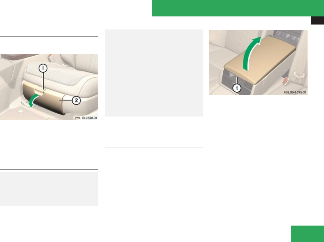
Loading and storing
417
Seat storage compartments
Storage compartments are located in the seat
base of each front seat.
1Handle
2Storage compartment lid
XOpening: Pull handle 1 up.
XFold storage compartment lid 2 forward.
Storage bags
GWarning!
Do not place objects with a combined
weight of more than 4.4 lb (2 kg) into the
storage bag. Otherwise, the Occupant
Classification System OCS may not be able
to properly approximate the occupant
weight category.
The storage bag is intended for storing
light-weight items only.
Heavy objects, objects with sharp edges or
fragile objects may not be transported in
the storage bag. In an accident, during hard
braking, or sudden maneuvers, they could
be thrown around inside the vehicle and
cause injury to vehicle occupants.
The storage bag cannot protect
transported goods in the event of an
accident.
Storage bags are located on the back of the
front seats.
Rear storage compartments
Armrest with integrated storage
compartment
! Before storing the armrest in the seat
backrest, close the storage compartment
cover.
! Do not sit on or lean your body weight
against the armrest when it is folded down,
as you could otherwise damage it.
Vehicles without control panel in rear armrest
1Release catch
XOpening: Pull down the armrest.
XPull release catch 1 and swing the storage
compartment cover upward in direction of
arrow.
Controls in detail
Z
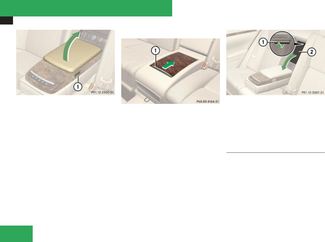
Loading and storing
418
Vehicles with control panel in rear armrest
1Button
XOpening: Press button 1 and swing the
storage compartment cover upward in
direction of arrow.
Storage compartment between rear seats
1Handle
XOpening: Pull handle 1 backward in the
direction of arrow.
Rear storage box
! Do not sit on or lean your body weight
against the armrest when it is folded down,
as you could otherwise damage it.
iWhen the rear seats are in their basic
position, you can open the cover more
easily.
1Handle
2Cover
XFold down rear armrest.
XPull handle 1 upward in direction of arrow.
XSwing down cover 2 in direction of arrow.
Storage spaces under trunk floor
Front storage space
You can place a suitcase in the hollow under
the front part of the trunk floor.
! Fold down the suitcase handle before
closing the trunk to avoid damaging the
trunk lid.
Controls in detail
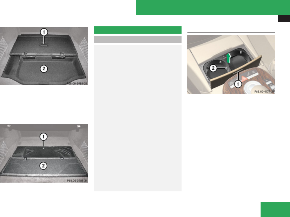
Useful features
419
1Trunk floor
2Suitcase storage space
Rear storage space
Only the S 600 is equipped with the rear
storage space.
1Storage space
2Trunk floor
Useful features
Cup holders
GWarning!
In order to help prevent spilling liquids on
vehicle occupants and/or vehicle
equipment, only use containers that fit into
the cup holder. Use lids on open containers
and do not fill containers to a height where
the contents, especially hot liquids, could
spill during braking, vehicle maneuvers, or
in an accident. Liquids spilled on vehicle
occupants may cause serious personal
injury. Liquids spilled on vehicle equipment
may cause damage not covered by the
Mercedes-Benz Limited Warranty.
When not in use, keep the cup holder
closed. An open cup holder may cause
injury to you or others when contacted
during braking, vehicle maneuvers, or in an
accident.
Keep in mind that objects placed in the cup
holder may come loose during braking,
vehicle maneuvers, or in an accident and be
thrown around in the vehicle interior.
Objects thrown around in the vehicle
interior may cause an accident and/or
serious personal injury.
Cup holder in front center console
1Chrome label
2Handle
XOpening: Press chrome label 1.
XClosing: Fold cover in until it engages.
The front cup holder can be removed for
cleaning purposes.
XRemoving: Pull cup holder out by pulling
handle 2 upward in direction of arrow.
XReinstalling: Press handle 2 downward
until it engages. While doing so, make sure
that the word “Front” is in the proper
installation position.
Controls in detail
Z
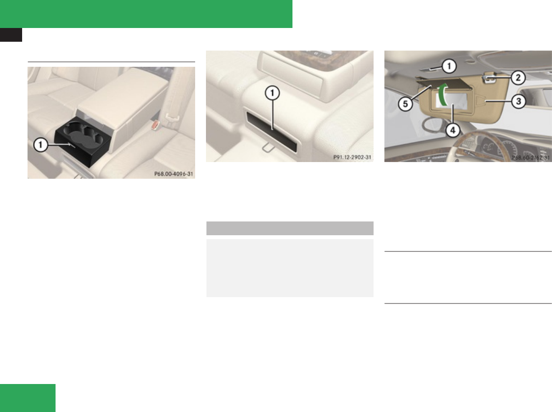
Useful features
420
Rear cup holder
Vehicles without control panel in rear armrest
1Chrome label
XOpening: Press chrome label 1.
Vehicles with control panel in rear armrest
1Cup holder
XOpening: Press front of cup holder 1.
Sun visors
GWarning!
Do not use the vanity mirror while driving.
Keep the vanity mirrors in the sun visors
closed while vehicle is in motion. Reflected
glare can endanger you and others.
1Vanity mirror lamp
2Mounting
3Holder, e.g. for gas cards
4Vanity mirror
5Vanity mirror cover
Glare through the windshield
XFlip sun visor down when you experience
glare.
Glare through a door window
XClose vanity mirror cover 5 if opened.
XDisengage sun visor from mounting 2.
XPivot sun visor to the side.
Controls in detail
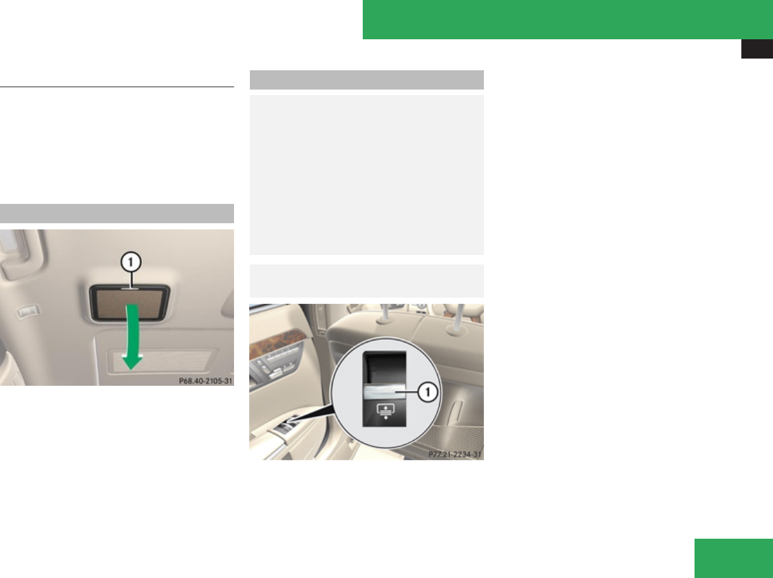
Useful features
421
Vanity mirror
The mirror lamp only functions when the sun
visor is engaged in mounting.
XFlip sun visor down.
XLift up vanity mirror cover 5.
Vanity mirror lamp 1 comes on.
Rear vanity mirror
1Mark
XOpening: Press mark 1.
The vanity mirror swings down in direction
of arrow.
XClosing: Swing vanity mirror up until it
engages.
Rear window sunshade
GWarning!
When operating the rear window sunshade
make sure there is no danger of anyone
being harmed by the extending or
retracting procedure.
The extending or retracting procedure can
be immediately halted by briefly pressing
rear window sunshade switch. To reverse
direction of movement, press rear window
sunshade switch again.
GObserve Safety notes, see
page 62.
1Rear window sunshade switch
You can also operate the rear window
sunshade via COMAND (Y page 225) or via
the favorite button (Y page 98). If you operate
the rear window sunshade via COMAND or via
the favorite button, this takes precedence
over the rear window sunshade buttons on
the rear doors.
iOperating the rear window sunshade
from the rear is not possible if you activate
the override switch (Y page 67).
iThe rear window sunshade is switched off
at temperatures below -4‡ (-20†).
Always extend the sunshade fully for its
support against the window frame.
XSwitch on the ignition.
XExtending/Retracting: Press or pull the
rear window sunshade switch 1 past the
resistance point.
Controls in detail
Z
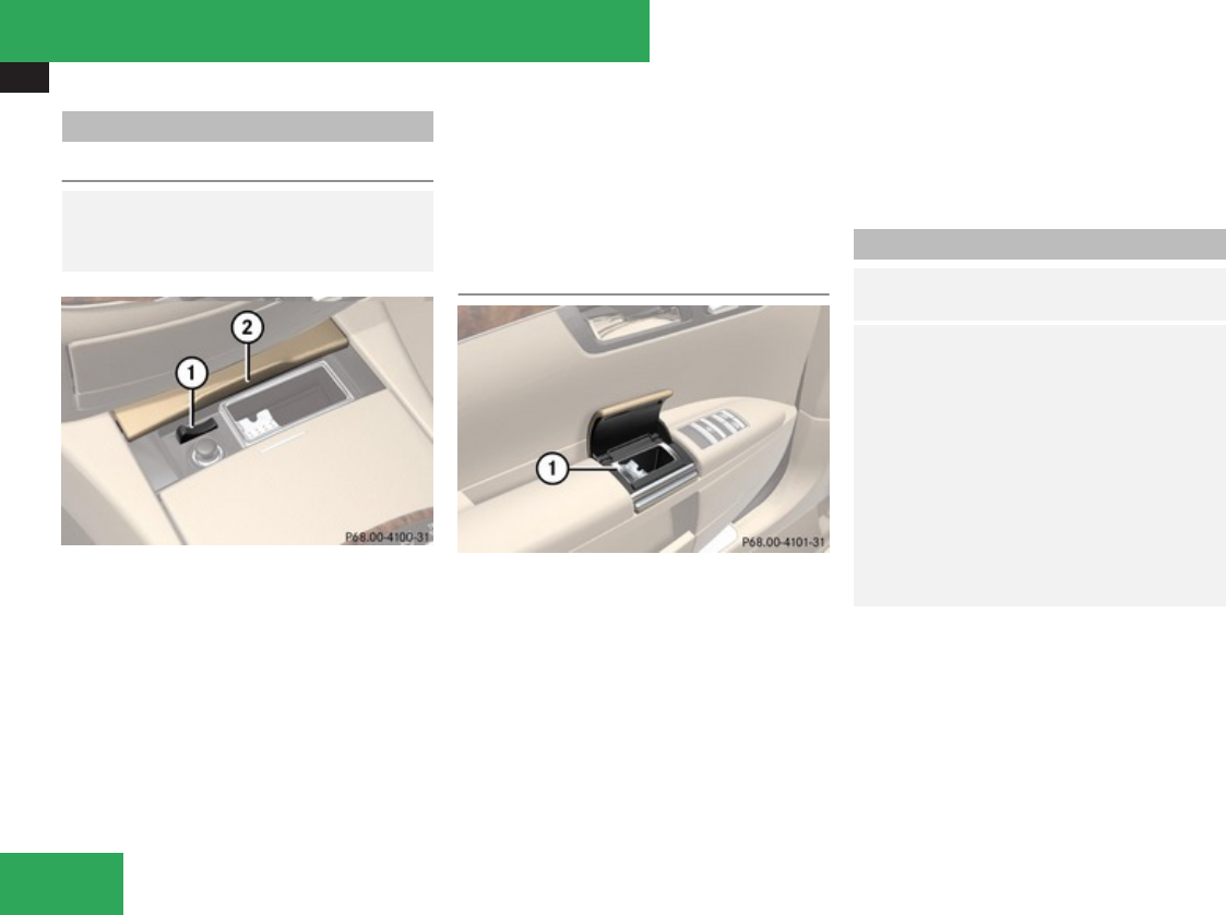
Useful features
422
Ashtrays
Center console ashtray
GWarning!
Remove front ashtray insert only with
vehicle standing still.
1Button
2Cover plate
XOpening: Press mark on cover plate 2
forward.
XRemoving ashtray insert: Push button
1 to the left.
The ashtray is disengaged and slides out a
short way.
XGrab and remove ashtray insert from
ashtray frame.
XReinstalling ashtray insert: Push the
ashtray insert back into the frame until it
engages.
XClosing: Briefly press mark on cover plate
2 forward.
Rear door ashtray
1Ashtray insert
XOpening: Lift up the cover.
XRemoving ashtray insert: Press the open
cover outwards beyond the stop.
Ashtray insert 1 pops out of the holder.
XRemove insert by pulling it upwards.
XReinstalling ashtray insert: Push ashtray
insert 1 back into frame until it engages.
XClosing: Push cover downwards.
Cigarette lighters
GObserve Safety notes, see
page 62.
GWarning!
Never touch the heating element or sides
of the lighter; they are extremely hot. Hold
the knob only.
Make sure any children traveling with you
do not injure themselves or start a fire with
the hot cigarette lighter.
To avoid possible injury to children sitting
in the rear seat, activate the override
switch. Activation of the override switch
deactivates the rear center console lighter.
If the engine is off and the cigarette lighter is
being used extensively, the vehicle battery
may become discharged.
Controls in detail
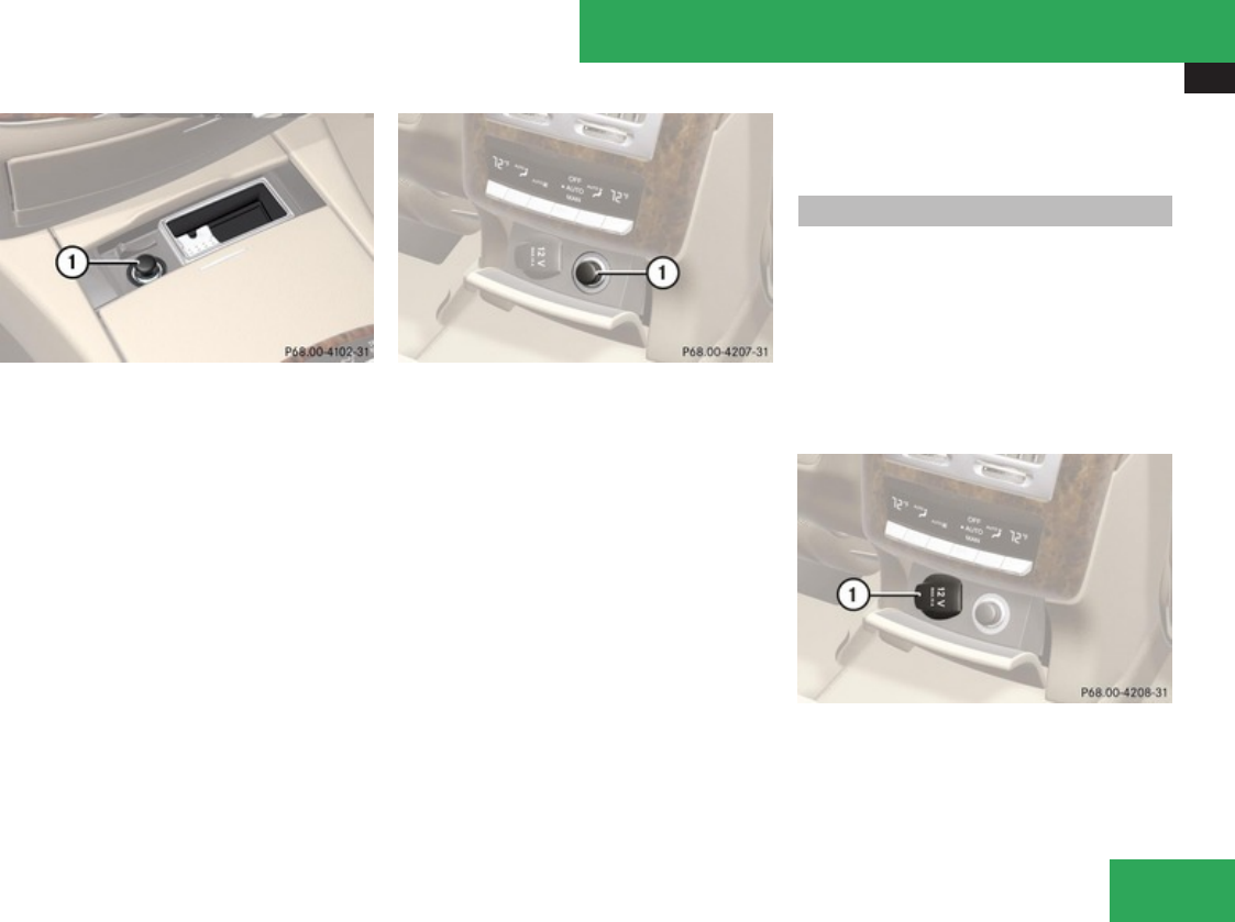
Useful features
423
Center console
1Cigarette lighter
XSwitch on the ignition.
XOpen the cover plate (Y page 422).
XPush in cigarette lighter 1.
Cigarette lighter 1 will pop out
automatically when hot.
XTake out cigarette lighter 1.
XReinsert cigarette lighter 1 in its socket
after use.
Rear center console
1Cigarette lighter
XSwitch on the ignition.
XOpen the cover plate.
XPush in cigarette lighter 1.
Cigarette lighter 1 will pop out
automatically when hot.
! The lighter socket can be used to
accommodate 12V DC electrical
accessories (up to a maximum of 85 W)
designed for use with the standard
“cigarette lighter” plug type. Keep in mind,
however, that connecting accessories to
the lighter socket (for example extensive
connecting and disconnecting, or using
plugs that do not fit properly) can damage
the lighter socket. With the socket
damaged, the lighter may not function
properly any longer.
Power outlets
The power outlets can be used to
accommodate 12V DC electrical accessories
(e.g. auxiliary lamps, mobile phone chargers)
up to a maximum of 15 A (180 W).
If the engine is off and the power outlets are
being used extensively, the vehicle battery
may become discharged.
XSwitch on the ignition.
Rear center console
1Power outlet
Controls in detail
Z
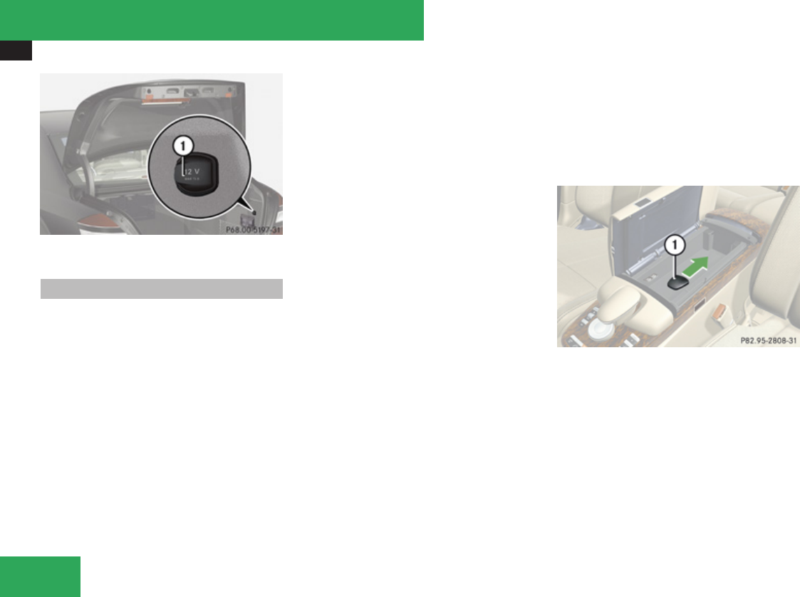
Useful features
424
1Power outlet
Telephone
iVarious mobile phone cradles can be
installed in the front center armrest, see
separate installation instructions for the
mobile phone cradle. These mobile phone
cradles can be obtained from an authorized
Mercedes-Benz Center.
The functions and services available to you
while using the mobile phone depend on
your service provider and the type of mobile
phone you are using. See also separate
operating manual for instructions on how
to use your mobile phone.
Radio transmitters, such as a portable
telephone or a citizens band unit, should only
be used inside the vehicle if they are
connected to an antenna that is installed on
the outside of the vehicle.
The external antenna must be approved by
Mercedes-Benz. Please contact an
authorized Mercedes-Benz Center for
information on the installation of an approved
external antenna. Refer to the radio
transmitter operation instructions regarding
use of an external antenna.
iThe roof cargo container may impair
mobile phone reception. In an emergency,
remove the mobile phone from the mobile
phone cradle to make a call.
When the mobile phone is inserted in the
cradle, you can operate the telephone using
the following devices:
Rmobile phone keypad
RCOMAND telephone keypad (Y page 85)
Rbuttons s and t on the
multifunction steering wheel (Y page 237)
RVoice Control System (Y page 254)
RBluetooth® headset (Y page 168)
Please note that these functions are only
available with Mercedes-Benz approved
mobile phones. Please contact an authorized
Mercedes-Benz Center for information on
features available for your mobile phone of
choice.
The contact plate for the mobile phone cradle
is located in the front center armrest.
XOpen telephone compartment
(Y page 416).
1Cover for contact plate
XPull cover for contact plate 1 in direction
of arrow.
You can now access the contact plate.
XInstall a mobile phone cradle, see separate
installation instructions for the cradle.
Controls in detail

Useful features
425
Tele Aid
! In order to activate the Tele Aid system, a
subscriber agreement must be completed.
To ensure your system is activated and
operational, please press the ¡ button
to perform the acquaintance call. Failure to
complete either of these steps may result
in a system that is not activated.
If you have any questions regarding
activation, please call the Response Center
at 1-800-756-9018 (in the USA) or
1-888-923-8367 (in Canada).
Shortly after the completion of your Tele Aid
acquaintance call, you will receive a user ID
and password in the mail. You may use this
password to access the Tele Aid section in
“Owner’s Online” at www.mbusa.com (USA
only). The “My Tele Aid” section will give you
access to account information, remote door
unlock and more.
The Tele Aid system is available if
Rit has been activated and is operational.
Activation requires a subscription for
monitoring services, connection and
cellular air time.
Rvehicle battery power is available.
Rthe relevant cellular phone network and
GPS signals are available and pass the
information on to the Response Center.
iLocation of the vehicle on a map is only
possible if the vehicle is able to receive
signals from the GPS satellite network and
pass the information on to the Response
Center.
The Tele Aid system
(Telematic Alarm Identification on Demand)
The Tele Aid system consists of three types
of response:
RAutomatic and manual emergency
RRoadside Assistance
RInformation
The Tele Aid system is operational providing
that the vehicle’s battery is charged, properly
connected, not damaged, and cellular and
GPS coverage is available. The Tele Aid
system utilizes the cellular network for
communication and the GPS (Global
Positioning System) satellites for vehicle
location. If either of these signals are
unavailable, the Tele Aid system may not
function and if this occurs, assistance must
be summoned by other means.
To adjust the speaker volume during a Tele
Aid call do the following:
XPress button æ or ç on the
multifunction steering wheel.
or
XUse the COMAND volume
thumbwheel , on the lower part of the
front center console (Y page 92).
System self-test
The system performs a self-test after you
have switched on the ignition.
GWarning!
If the indicator lamps in the SOS button, in
the Roadside Assistance button p and/
or in the Information button ¡ do not
come on during the system self-test, or if
any of these indicators remain illuminated
constantly in red and/or the message Tele
Aid Not Activated or Tele Aid
Inoperative is displayed in the
multifunction display after the system self-
Controls in detail
Z

Useful features
426
test, a malfunction in the system has been
detected.
If a malfunction is indicated as outlined
above, the system may not operate as
expected. In case of an emergency, help
will have to be summoned by other means.
Have the system checked at the nearest
Mercedes-Benz Center or contact the
Response Center at 1-800-756-9018 (in
the USA) or 1-888-923-8367 (in Canada) as
soon as possible.
Emergency calls
! In order to activate the Tele Aid system, a
subscriber agreement must be completed.
To ensure your system is activated and
operational, please press the ¡ button
to perform the acquaintance call. Failure to
complete either of these steps may result
in a system that is not activated.
If you have any questions regarding
activation, please call the Response Center
at 1-800-756-9018 (in the USA) or
1-888-923-8367 (in Canada).
An emergency call is initiated automatically
following an accident in which the Emergency
Tensioning Devices (ETDs) or air bags deploy.
An emergency call can also be initiated
manually (Y page 427).
Once the emergency call is in progress, the
indicator lamp in the SOS button will begin to
flash. The message Connecting Call
appears in the multifunction display.
Emergency Call Activated appears in the
COMAND display and the audio system is
muted. When the connection is established,
the message Call Connected appears in the
multifunction display. Emergency Call
Activated appears in the COMAND display.
All information relevant to the emergency,
such as the location of the vehicle
(determined by the GPS satellite location
system), vehicle model, identification number
and color are generated.
iDuring the emergency call message
Emergency Call Activated is displayed,
operation from audio system or COMAND
system is not possible. The climate control
can be still adjusted using the switches on
the climate control panel.
A voice connection between the Response
Center and the occupants of the vehicle will
be established automatically soon after the
emergency call has been initiated. The
Response Center will attempt to determine
more precisely the nature of the emergency
provided they can speak to an occupant of
the vehicle.
iIf no vehicle occupant responds, an
ambulance will be sent to the vehicle
immediately.
GWarning!
If the indicator lamp in the SOS button is
flashing continuously and there was no
voice connection to the Response Center
established, then the Tele Aid system could
not initiate an emergency call (e.g. the
relevant cellular phone network is not
available).
The message Call Failed appears in the
multifunction display for approximately
10 seconds.
Should this occur, assistance must be
summoned by other means.
iDuring the emergency call the telephone
is switched off automatically and must be
switched back on to make a call.
iThe “911” emergency call system is a
public service. Using it without due cause
is a criminal offense.
Controls in detail
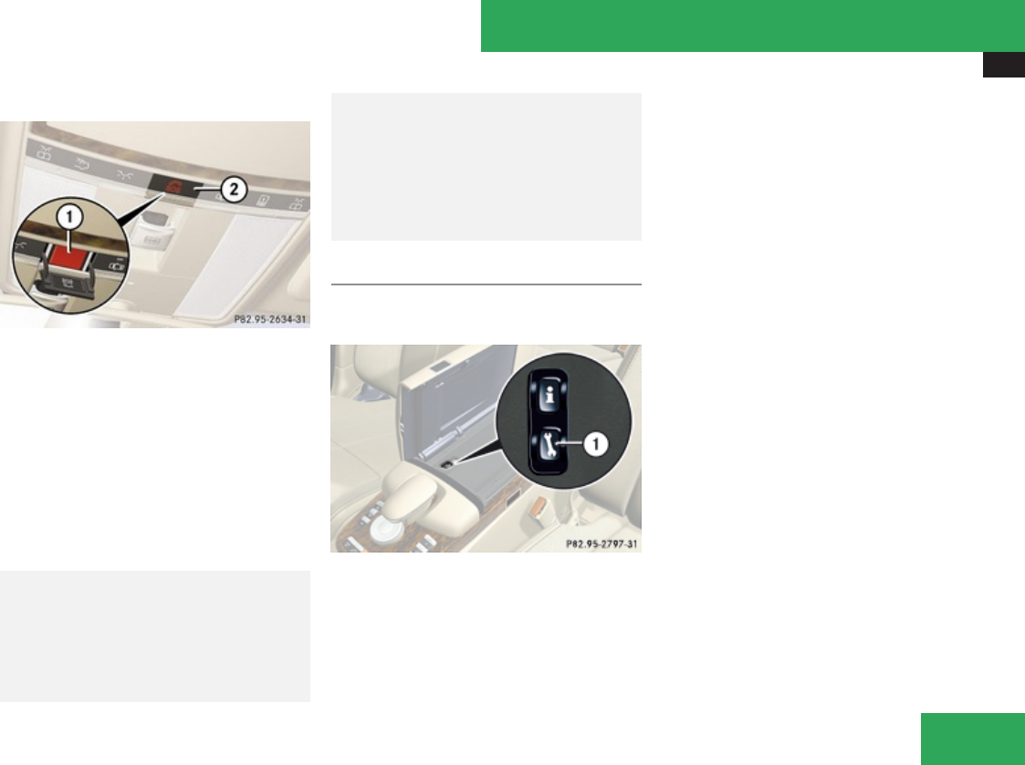
Useful features
427
Initiating an emergency call manually
1SOS button
2Cover
XBriefly press on cover 2 to open.
XPress SOS button 1 briefly.
The indicator lamp in SOS button 1 will
flash until the emergency call is concluded.
XWait for a voice connection to the
Response Center.
XClose cover 2 after the emergency call is
concluded.
GWarning!
If you feel at any way in jeopardy when in
the vehicle (e.g. smoke or fire in the vehicle,
vehicle in a dangerous road location),
please do not wait for voice contact after
you have pressed the emergency button.
Carefully leave the vehicle and move to a
safe location. The Response Center will
automatically contact local emergency
officials with the vehicle’s approximate
location if they receive an automatic SOS
signal and cannot make voice contact with
the vehicle occupants.
Roadside Assistance button
XOpen the storage compartment
(Y page 416).
1Roadside Assistance button p
XPress and hold Roadside Assistance button
p for longer than 2 seconds.
A call to a Mercedes-Benz Roadside
Assistance dispatcher will be initiated. The
indicator lamp in the Roadside Assistance
button p will flash while the call is in
progress. The message Connecting
Call will appear in the multifunction
display. Roadside Assistance
Activated appears in the COMAND
Display. The audio system or the COMAND
system is muted.
When the connection is established, the
message Call Connected appears in the
multifunction display. Roadside
Assistance Activated appears in the
COMAND display. The Tele Aid system will
transmit data generating the vehicle
identification number, model, color and
location (subject to availability of cellular and
GPS signals).
i The COMAND system display indicates
that a Tele Aid call is in progress. While the
call is connected you can change to the
navigation menu by pressing the N
shortcut button. Spoken commands are
not available.
A voice connection between the Roadside
Assistance dispatcher and the occupants of
the vehicle will be established.
XDescribe the nature of the need for
assistance.
Controls in detail
Z
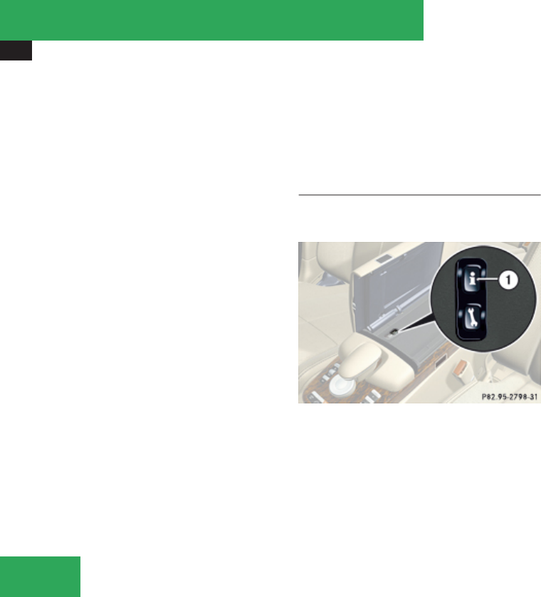
Useful features
428
The Mercedes-Benz Roadside Assistance
dispatcher will either dispatch a qualified
Mercedes-Benz technician or arrange to tow
your vehicle to the nearest authorized
Mercedes-Benz Center. For services such as
labor and/or towing, charges may apply.
Refer to the Roadside Assistance manual for
more information.
The following is only available in the USA:
Sign and Drive services: Services such as a
jump start, a few gallons of fuel or the
replacement of a flat tire with the vehicle
spare tire are obtainable at no charge.
iIf the indicator lamp in the Roadside
Assistance button p is flashing
continuously and there was no voice
connection to the Response Center
established, then the Tele Aid system could
not initiate a Roadside Assistance call (e.g.
the relevant cellular phone network is not
available). The message Call Failed
appears in the multifunction display. Call
could not be connected! appears in the
COMAND display. Confirm the message
pressing n (Y page 85).
XTerminating calls: Press button t on
the multifunction steering wheel.
or
XPress the respective button for ending a
telephone call on the telephone keypad.
Information button
XOpen the storage compartment
(Y page 416).
1Information button ¡
XPress and hold Information button ¡ for
longer than 2 seconds.
A call to the Customer Assistance Center
will be initiated. The indicator lamp in the
Information button ¡ will flash while the
call is in progress. The message
Connecting Call will appear in the
multifunction display. Information Call
Activated appears in the COMAND
display. The audio system or the COMAND
system is muted.
When the connection is established, the
message Call Connected appears in the
multifunction display. The Tele Aid system will
transmit data generating the vehicle
identification number, model, color and
location (subject to availability of cellular and
GPS signals).
When the connection is established, the
message Call Connected appears in the
multifunction display. Information Call
Activated appears in the COMAND display.
The Tele Aid system will transmit data
generating the vehicle identification number,
model, color and location (subject to
availability of cellular and GPS signals).
i The COMAND system display indicates
that a Tele Aid call is in progress. While the
call is connected you can change to the
navigation menu by pressing the N
shortcut button. Spoken commands are
not available.
A voice connection between the Customer
Assistance Center representative and the
occupants of the vehicle will be established.
Controls in detail

Useful features
429
Information regarding the operation of your
vehicle, the nearest authorized Mercedes-
Benz Center or Mercedes-Benz USA products
and services is available to you.
For more details concerning the Tele Aid
system, please visit www.mbusa.com (USA
only), log in to “Owner’s Online” and visit the
“My Tele Aid” section to learn more.
iIf the indicator lamp in the Information
button ¡ is flashing continuously and
there was no voice connection to the
Response Center established, then the Tele
Aid system could not initiate an Information
call (e.g. the relevant cellular phone
network is not available). The message
Call Failed appears in the multifunction
display. Call could not be
connected! appears in the COMAND
display. Confirm the message pressing n
(Y page 85).
XTerminating calls: Press button t on
the multifunction steering wheel.
or
XPress the respective button for ending a
telephone call on the telephone keypad.
Call priority
If other service calls such as a Roadside
Assistance call or Information call are active,
an emergency call is still possible. In this
case, the emergency call will take priority and
override all other active calls.
The indicator lamp in the respective button
flashes until the call is concluded. Emergency
calls can only be terminated by a Response
Center or Customer Assistance Center
representative. All other calls can be
terminated by pressing button t on the
multifunction steering wheel or the
respective button for ending a telephone call
on the telephone keypad.
iWhen a Tele Aid call has been initiated,
the audio system is muted. The optional
mobile phone (if installed) switches off. If
you must use this phone, we recommend
that you use it only with the vehicle at a
standstill in a safe location. Unplug the
telephone, switch it on and place the call.
The navigation system (if engaged) will
continue to run. The multifunction display
in the instrument cluster is available for
use, but spoken commands are not
available.
Destination Download to the COMAND
system
iThe components and operating principles
of the COMAND system can be found on
(Y page 83).
Destination Download allows you access to a
database of over 10 million points of interest
(POIs) that can be downloaded to your
vehicle’s navigation system. If you know the
destination, the address can be downloaded,
or can be provided with points of interests
near your location.
The Response Center can transmit
destination data to the COMAND system
during the connection with the Roadside
Assistance or Customer Assistance Center.
The transmitted data can contain address
details for a Mercedes-Benz Center or POIs.
Route guidance
You will be prompted to confirm that route
guidance to the entered address is to be
started.
XSlide qmr or rotate ymz to select Yes
menu item and confirm by pressing n.
The system calculates the route and
subsequently starts the route guidance to the
defined address.
Controls in detail
Z
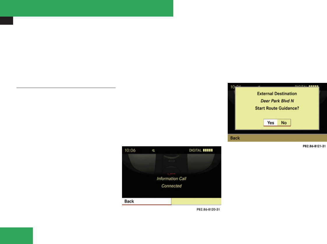
Useful features
430
iIf you select No, you can save the address
to your address book.
iThe Destination Download feature is
available if the relevant mobile phone
network is available and data connection is
possible.
Search and Send
iIn order to utilize Search & Send your
vehicle must be equipped with Tele Aid,
Navigation, and an active Tele Aid
subscription.
“Search & Send” is a navigation destination
address entry service. A destination address
located using Google Maps® or Yahoo Local
Maps® website can be delivered via Tele Aid
directly to the navigation system in your
vehicle.
Specify and Send a Destination Address
iPlease refer to any specific instructions
provided by either website regarding
entering or sending an address. Each
website functions differently and is subject
to change.
XGo to www.maps.google.com or
www.maps.yahoo.com and enter a
destination address in the address entry
field.
XDepending on which website you are using,
click on the appropriate button to send the
destination address to your Tele Aid
account email address.
XEnter the email address you specified when
you activated your Tele Aid account in the
appropriate field when the “Send” dialog
box appears.
XClick “Send”.
Retrieve Destination Address
XPress the Tele Aid Information button to
begin the download of the destination
address to your vehicle’s navigation
system.
iIf you have sent more than one
destination address to your vehicle you
must make one Information call for each
destination address download.
XSelect Yes when the message appears
asking if you would like to start navigation.
This will open the start navigation screen.
XSelect Start.
or
XSelect No if you wish to save the
downloaded destination address in the
From Memory destination list for future
use.
Controls in detail
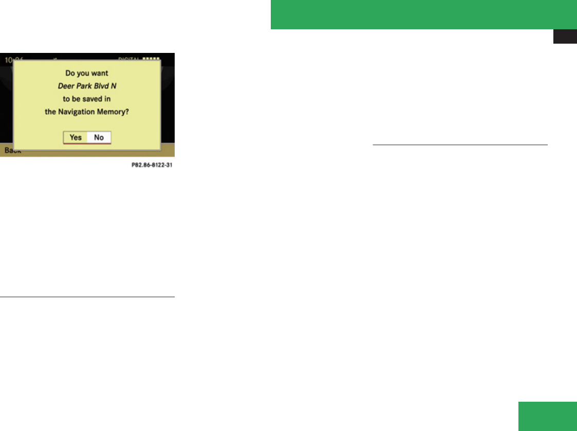
Useful features
431
iDestination addresses will download in
the same order they were sent. If you have
multiple Mercedes-Benz vehicles equipped
with Tele Aid and active accounts, each
destination address sent will be retrievable
by all vehicles associated with the e-mail
address you specified for your Tele Aid
account.
Remote door unlock
In case you have locked your vehicle
unintentionally (e.g. SmartKey inside vehicle),
and the reserve SmartKey is not available:
XContact the Response Center at
1-800-756-9018 (in the USA) or
1-888-923-8367 (in Canada).
You will be asked to provide your password.
XThen return to your vehicle at the time
arranged with the Response Center and
pull the trunk lid handle for a minimum of
20 seconds until the indicator lamp in the
SOS button is flashing.
The message Connecting Callappears in
the multifunction display.
As an alternative, you may unlock the vehicle
via Internet in the “My Tele Aid” section of
“Owner’s Online”, using your ID and password
(USA only).
The Response Center will then unlock your
vehicle with the remote door unlocking
feature.
iThe remote door unlock feature is
available if the relevant cellular phone
network is available.
The SOS button will flash and the message
Connecting Call will appear in the
multifunction display to indicate receipt of
the door unlock command.
Once the vehicle is unlocked, a Response
Center specialist will attempt to establish
voice contact with the vehicle occupants.
If the trunk lid handle was pulled for more
than 20 seconds before door unlock
authorization was received by the
Response Center, you must wait
15 minutes before pulling the trunk lid
handle again.
Remote door lock
If you have forgotten to lock your vehicle and
are no longer near it, you can have it locked
remotely through the Response Center.
The vehicle can be remotely locked within
4 days after the ignition has been switched
off.
XContact the Response Center at
1-800-756-9018 (in the USA) or
1-888-923-8367 (in Canada).
You will be asked to provide your password.
When you are inside your vehicle the next
time and switch on the ignition, the message
Tele Aid Doors Locked Remotely will
appear on the multifunction display.
iThe remote door lock feature is available
if the relevant telephone network is
available and data connection is possible.
Controls in detail
Z

Useful features
432
Automatic Maintenance Call
The S-Class is equipped with a feature that
considerably enhances vehicle care. Just
prior to reaching a vehicle maintenance
milestone, Tele Aid transmits important
vehicle maintenance information that alerts
your authorized Mercedes-Benz Center of
required service. This is automatic and does
not require driver intervention. This feature
allows your preferred Mercedes-Benz Center
to significantly improve the process of
arranging your service appointment and
ensures that your vehicle receives the best
possible care.
iThe Automatic Maintenance Call feature
is available if the relevant telephone
network is available and data connection is
possible.
Stolen Vehicle Recovery services
In the event your vehicle was stolen:
XReport the incident to the police.
The police will issue a numbered incident
report.
XPass this number on to the Response
Center along with your password.
The Response Center will then attempt to
covertly contact the vehicle’s Tele Aid
system. Once the vehicle is located, the
Response Center will contact the local law
enforcement and you. The vehicle’s
location will only be provided to law
enforcement.
iIf the anti-theft alarm stays on for more
than 30 seconds, a call to the Response
Center is initiated automatically by the Tele
Aid system provided Tele Aid service was
subscribed to and properly activated, and
that necessary cellular service and GPS
coverage are available. See “Anti-theft
alarm system” (Y page 79).
Garage door opener
The integrated remote control can operate up
to three separately controlled devices
compatible with HomeLink® or some other
systems.
GWarning!
Before programming the integrated remote
control to a garage door opener or gate
operator, make sure people and objects are
out of the way of the device to prevent
potential harm or damage. When
programming a garage door opener, the
door moves up or down. When
programming a gate operator, the gate
opens or closes.
Do not use the integrated remote control
with any garage door opener that lacks
safety stop and reverse features as
required by U.S. federal safety standards
(this includes any garage door opener
model manufactured before April 1, 1982).
A garage door that cannot detect an object
- signaling the door to stop and reverse -
does not meet current U.S. federal safety
standards.
When programming a garage door opener,
park vehicle outside the garage.
Do not run the engine while programming
the integrated remote control. Inhalation of
exhaust gas is hazardous to your health. All
exhaust gas contains carbon monoxide
(CO), and inhaling it can cause
unconsciousness and possible death.
Controls in detail
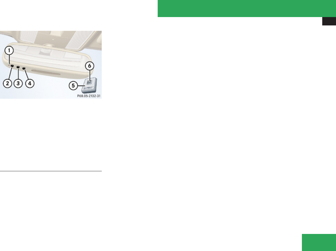
Useful features
433
Interior rear view mirror with integrated remote
control
1Indicator lamp
234 Signal transmitter button
5Hand-held remote control (not part
of vehicle equipment)
6Hand-held remote control button
Programming the integrated remote
control
XStep 1: Switch on the ignition.
XStep 2: If you have previously programmed
a signal transmitter button and wish to
retain its programming, proceed to step 3.
or
XIf you are programming the integrated
remote control for the first time, press and
hold the two outer signal transmitter
buttons 2 and 4 and release them when
indicator lamp 1 begins to flash after
approximately 20 seconds.
Do not hold the button for longer than
30 seconds.
This procedure erases any previous
settings for all three channels and
initializes the memory. If you later wish to
program a second and/or third hand-held
transmitter to the remaining two signal
transmitter buttons, do not repeat this step
and begin directly with step 3.
XStep 3: Hold the end of hand-held remote
control 5 of the device you wish to train
approximately 2 to 12 in (5 to 30 cm) away
from the signal transmitter button (2, 3
or 4) to be programmed, while keeping
indicator lamp 1 in view.
XStep 4: Using both hands, simultaneously
press hand-held remote control button 6
and the desired signal transmitter button
(2, 3 or 4). Do not release the buttons
until step 5 is completed.
Indicator lamp 1 will flash, first slowly and
then rapidly.
iIndicator lamp 1 flashes immediately
the first time the signal transmitter button
is programmed. If this button has already
been programmed, the indicator lamp will
start flashing after 20 seconds.
XStep 5: After indicator lamp 1 changes
from a slow to a rapidly flashing light,
release the hand-held remote control
button and the signal transmitter button.
XStep 6: Press and hold the just-trained
signal transmitter button (2, 3 or 4) and
observe indicator lamp 1.
If indicator lamp 1 stays on constantly,
programming is complete and your device
should activate when the respective signal
transmitter button (2, 3 or 4) is pressed
and released.
iIf indicator lamp 1 flashes rapidly for
approximately 2 seconds and then turns to
a constant light, continue with
programming steps 8 through 12 as your
garage door opener may be equipped with
the “rolling code” feature.
XStep 7: To program the remaining two
signal transmitter buttons, repeat the steps
above starting with step 3.
Controls in detail
Z

Useful features
434
Rolling code programming
To train a garage door opener (or other rolling
code devices) with the rolling code feature,
follow these instructions after completing the
“Programming” portion (steps 1 through 6) of
this text. A second person may make the
following training procedures quicker and
easier.
XStep 8: Locate the “training” button on the
garage door opener motor head unit.
iExact location and color of the button may
vary by garage door opener brand.
Depending on manufacturer, the “training”
button may also be referred to as “learn”or
“smart” button. If there is difficulty locating
the transmitting button, refer to the garage
door opener Operator’s Manual.
XStep 9: Press the “training” button on the
garage door opener motor head unit.
The “training light” is activated.
You have 30 seconds to initiate the
following two steps.
XStep 10: Return to the vehicle and firmly
press, hold for 2 seconds and release the
programmed signal transmitter button
(2, 3 or 4).
XStep 11: Press, hold for 2 seconds and
release same signal transmitter button a
second time to complete the training
process.
iSome garage door openers (or other
rolling code equipped devices) may require
you to press, hold for 2 seconds and
release the same signal transmitter button
a third time to complete the training
process.
XStep 12: Confirm the garage door
operation by pressing the programmed
signal transmitter button (2, 3 or 4).
XStep 13: To program the remaining two
signal transmitter buttons, repeat the steps
above starting with step 3.
Gate operator/Canadian programming
Canadian radio-frequency laws require
transmitter signals to “time-out” (or quit)
after several seconds of transmission which
may not be long enough for the integrated
signal transmitter to pick up the signal during
programming. Similar to this Canadian law,
some U.S. gate operators are designed to
“time-out” in the same manner.
If you live in Canada or if you are having
difficulties programming a gate operator
(regardless of where you live) by using the
programming procedures, replace step 4 with
the following:
XStep 4: Press and hold the signal
transmitter button (2, 3 or 4). Do not
release this button until it has been
successfully trained.
XWhile still holding down the signal
transmitter button (2, 3 or 4), “cycle”
your hand-held remote control button 6
as follows: Press and hold button 6 for
2 seconds, then release it for 2 seconds,
and again press and hold it for 2 seconds.
Repeat this sequence on the hand-held
remote control until the frequency signal
has been learned.
Upon successful training, indicator lamp
1 will flash slowly and then rapidly after
several seconds.
XProceed with programming step 5 and
step 6 to complete.
iUpon completion of programming the
integrated remote control, make sure you
retain the hand-held remote control that
came with the garage door opener, gate
operator or other device. You may need it
for use in other vehicles, for future
programming of an integrated remote
control, or simply for continued use as a
hand-held remote control to operate the
respective device in other situations.
Controls in detail

Useful features
435
Reprogramming a single signal
transmitter button
To program a device using a signal
transmitter button previously trained, follow
these steps:
XSwitch on the ignition.
XPress and hold the desired signal
transmitter button (2, 3 or 4). Do not
release the button.
Indicator lamp 1 will begin to flash after
20 seconds.
XWithout releasing the signal transmitter
button, proceed with programming starting
with step 3.
Operation of integrated remote control
XSwitch on the ignition.
XSelect and press the appropriate
integrated signal transmitter button (2,
3 or 4) to activate the remote controlled
device.
The integrated remote control transmitter
continues to send the signal as long as the
button is pressed – up to 20 seconds.
Erasing the integrated remote control
memory
iIf you sell your vehicle, erase the codes of
all three channels.
XSwitch on the ignition.
XSimultaneously press and hold outer signal
transmitter buttons 2 and 4, for
approximately 20 seconds, until indicator
lamp 1 flashes rapidly. Do not hold for
longer than 30 seconds.
The codes of all three channels are erased.
Programming tips
If you are having difficulty programming the
integrated remote control, here are some
helpful tips:
RCheck the frequency of hand-held remote
control 5 (typically located on the reverse
side of the remote). The integrated remote
control is compatible with radio-frequency
devices operating between 280-390 MHz.
RPut a new battery in hand-held remote
control 5. This will increase the likelihood
of the hand-held remote control sending a
faster and more accurate signal to the
integrated remote control.
RWhile performing step 3, hold hand-held
remote control 5 at different lengths and
angles from the signal transmitter button
(2, 3 or 4) you are programming.
Attempt varying angles at the distance of 2
to 12 inches (5 to 30 cm) away or the same
angle at varying distances.
RIf another hand-held remote control is
available for the same device, try the
programming steps again using that other
hand-held remote control. Make sure new
batteries are in the hand-held remote
control before beginning the procedure.
RStraighten the antenna wire from the
garage door opener assembly. This may
help improve transmitting and/or receiving
signals.
iCertain types of garage door openers are
incompatible with the integrated remote
control. If you should experience further
difficulties with programming the
integrated remote control, contact an
authorized Mercedes-Benz Center, or call
the Mercedes-Benz Customer Assistance
Center (in the USA) at
1-800-FOR-MERCedes, or Customer
Service (in Canada) at 1-800-387-0100.
Controls in detail
Z

Useful features
436
iUSA only:
This device complies with Part 15 of the
FCC Rules. Operation is subject to the
following two conditions:
1. This device may not cause harmful
interference, and
2. this device must accept any
interference received, including
interference that may cause undesired
operation.
Any unauthorized modification to this
device could void the user’s authority to
operate the equipment.
iCanada only:
This device complies with RSS-210 of
Industry Canada. Operation is subject to
the following two conditions:
1. This device may not cause interference,
and
2. this device must accept any
interference received, including
interference that may cause undesired
operation of the device.
Any unauthorized modification to this
device could void the user’s authority to
operate the equipment.
Floormats
GWarning!
Whenever you are using floormats, make
sure there is enough clearance and that the
floormats are securely fastened.
Floormats should always be securely
fastened using the fastening equipment.
Before driving off, check that the floormats
are securely in place and adjust them if
necessary. A loose floormat could slip and
hinder proper functioning of the pedals.
Do not place several floormats on top of
each other as this may impair pedal
movement.
iTo install or remove the floormat more
easily, move the driver’s seat or front
passenger seat as far to the rear as
possible.
1Retainer pin
2Eyelet
XRemoving: Pull floormat off of retainer pins
1.
XInstalling: Press floormat eyelets 2 onto
retainer pins 1.
Controls in detail
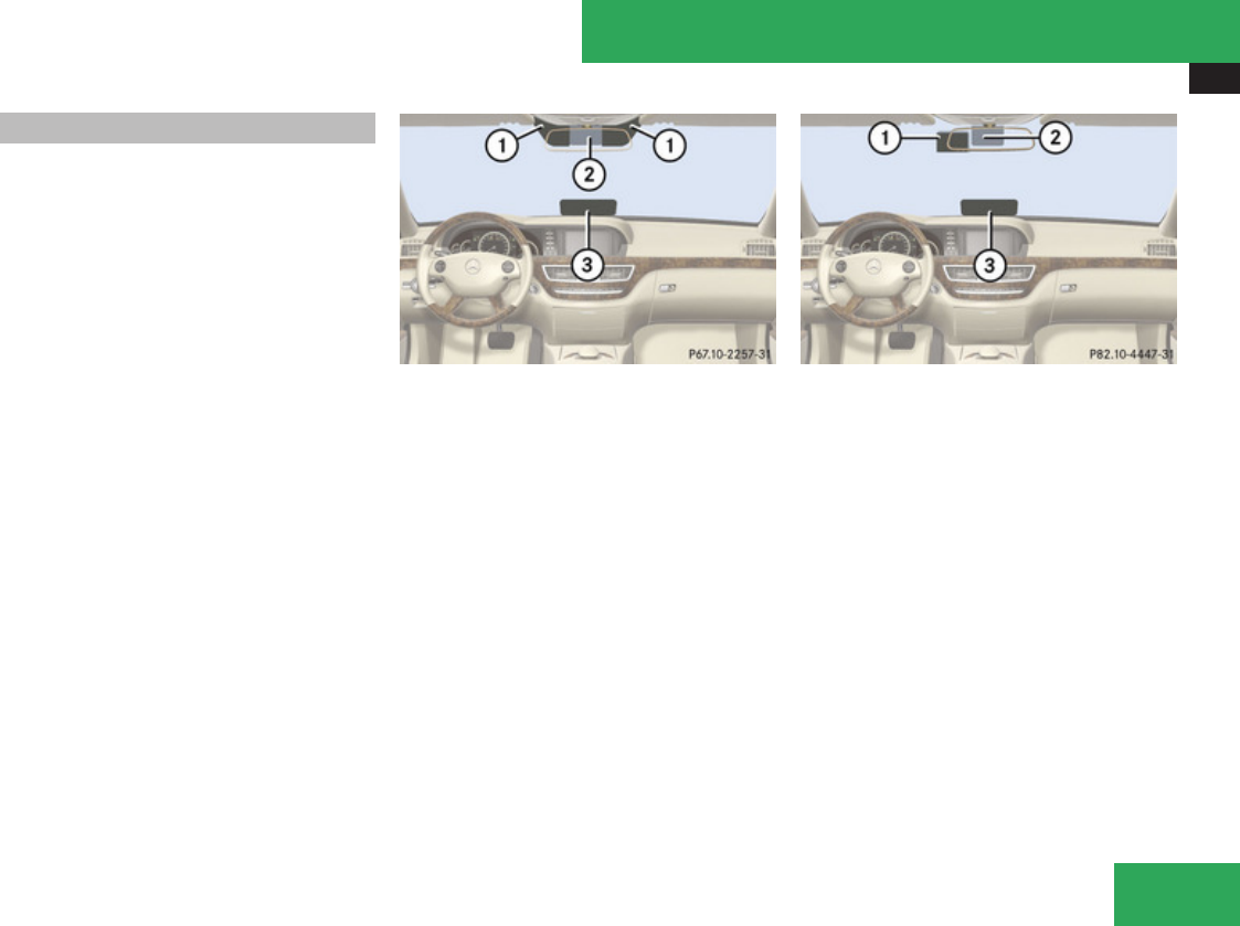
Useful features
437
Infrared reflecting windshield
Infrared reflecting glass reduces the amount
of radiated heat entering the vehicle interior
through the windows.
The infrared reflecting glass also prevents the
transmission of signals through the glass by
in-vehicle electronic devices, e.g. electronic
toll collection devices.
To allow the use of these devices in the
vehicle, infrared transparent areas 1 and
3 are placed in the windshield.
You can see them from certain angles when
ambient light condition permit.
Vehicles without Night View Assist
1Infrared transparent area (located left and
right to the cover of the rain light sensor)
2Cover of the rain light sensor
3Infrared transparent area
Vehicles with Night View Assist
1Infrared transparent area (located left to
the cover of the rain light sensor)
2Cover of the rain light sensor
3Infrared transparent area
Controls in detail
Z

438
439
Vehicle equipment ............................ 440
The first 1000 miles (1500 km) ....... 440
At the gas station ............................. 441
Engine compartment ........................ 443
Tires and wheels ............................... 450
Winter driving ................................... 473
Driving instructions .......................... 475
Maintenance ...................................... 481
Vehicle care ....................................... 483
Operation

The first 1000 miles (1500 km)
440
Vehicle equipment
iThis Operator’s Manual describes all
features, standard or optional, potentially
available for your vehicle at the time of
purchase. Please be aware that your
vehicle might not be equipped with all
features described in this manual.
The first 1000 miles (1500 km)
The more cautiously you treat your vehicle
during the break-in period, the more satisfied
you will be with its performance later on.
RDrive your vehicle during the first
1 000 miles (1 500 km) at varying but
moderate vehicle and engine speeds.
RDuring this period, avoid heavy loads (full
throttle driving) and excessive engine
speeds (no more than 2/3 of maximum rpm
in each gear).
RSelect C as the preferred shift program
(Y page 350) for the first 1 000 miles
(1 500 km).
RAvoid accelerating by kickdown.
RDo not attempt to slow the vehicle down by
shifting to a lower gear using the gear
selector lever.
RSelect gear ranges 3, 2 or 1 (Y page 350)
only when driving at moderate speeds (for
hill driving).
After 1 000 miles (1 500 km) you may
gradually increase vehicle and engine speeds
to the permissible maximum.
! Additional instructions for AMG vehicles:
RDuring the first 1 000 miles (1 500 km),
do not exceed a speed of 85 mph
(140 km/h).
RDuring this period, avoid engine speeds
above 4 500 rpm in each gear.
RShift gears in a timely manner.
All of the above instructions, as may apply to
your vehicle type, also apply when driving the
first 1 000 miles (1 500 km) after the engine
or the rear differential has been replaced.
iAlways obey applicable speed limits.
Operation

At the gas station
441
At the gas station
Refueling
GWarning!
Gasoline is highly flammable and
poisonous. It burns violently and can cause
serious personal injury.
Never allow sparks, flames or smoking
materials near gasoline!
Turn off the engine before refueling.
Whenever you are around gasoline, avoid
inhaling fumes and any skin or clothing
contact. Extinguish all smoking materials.
Direct skin contact with fuels and the
inhalation of fuel vapors are damaging your
health.
GWarning!
Overfilling of the fuel tank may create
pressure in the system which could cause
a gas discharge. This could cause the gas
to spray back out when removing the fuel
pump nozzle, which could cause personal
injury.
! Never refuel vehicles with gasoline engine
with diesel fuel. Even small amounts of
diesel fuel will damage the fuel system and
engine. Damage resulting from the use of
non-approved fuels or fuel additives or
resulting from mixing gasoline with diesel
fuel is not covered by the Mercedes-Benz
Limited Warranty.
! If you have accidentally filled the tank
with incorrect or non-approved fuel, do not
switch on the ignition. Otherwise the
incorrect or non-approved fuel will get into
the fuel lines. The fuel system must be
drained completely. Contact an authorized
Mercedes-Benz Center to have the fuel
system drained completely.
! To prevent damage to the catalytic
converters, only use premium unleaded
gasoline in this vehicle.
Any noticeable irregularities in engine
operation should be repaired promptly.
Otherwise, excessive unburned fuel may
reach the catalytic converter, causing it to
overheat and potentially start a fire.
i Only use premium unleaded gasoline with
a minimum Posted Octane Rating of 91
(average of 96 RON/86 MON).
Information on gasoline quality can
normally be found on the fuel pump. Please
contact gas station personnel in case
labels on the pump cannot be found.
For more information on gasoline, see
“Premium unleaded
gasoline” (Y page 608), see “Fuel
requirements” (Y page 608), or contact an
authorized Mercedes-Benz Center, or visit
www.mbusa.com (USA only).
The fuel filler flap is located on the right-hand
side of the vehicle towards the rear.
Locking/unlocking the vehicle with the
SmartKey automatically locks/unlocks the
fuel filler flap.
iIn case the central locking system does
not release the fuel filler flap, or the
opening mechanism is clamping, contact
Roadside Assistance or an authorized
Mercedes-Benz Center.
Operation
Z
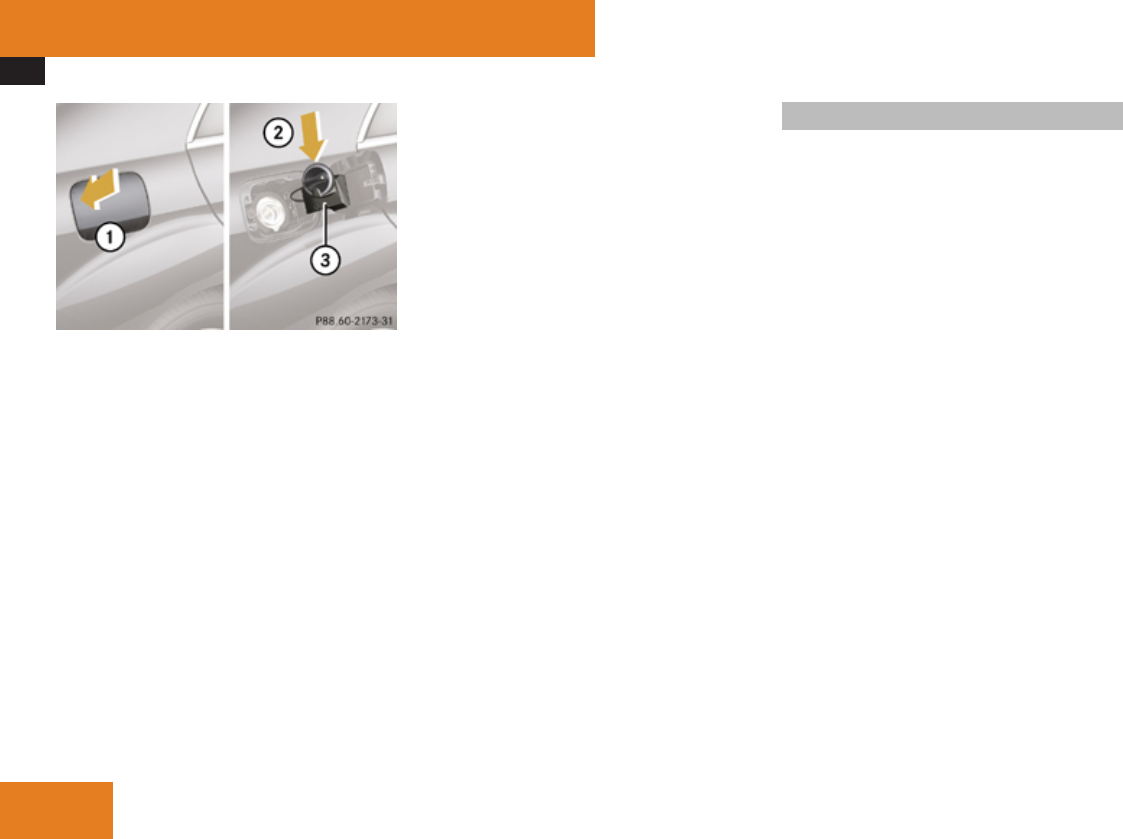
At the gas station
442
1Fuel filler flap
2Fuel filler cap
3Holder
XTurn off the engine.
iLeaving the engine running and the fuel
filler cap open can cause the yellow engine
malfunction indicator lamp ± to
illuminate.
For more information, see also “Practical
hints” (Y page 557).
XRemove the SmartKey from the starter
switch.
KEYLESS-GO: Open the driver’s door (this
puts the starter switch in position 0, same
as with the SmartKey removed from the
starter switch). The driver’s door then can
be closed again.
XOpening: Press fuel filler flap 1 at the
point indicated by the arrow.
XTurn fuel filler cap 2 counterclockwise.
XTake off fuel filler cap 2.
XPlace fuel filler cap 2 in direction of arrow
into holder 3.
XFully insert filler nozzle unit and refuel.
XOnly fill your tank until the filler nozzle unit
cuts out – do not top off or overfill.
XClosing: Turn fuel filler cap 2 clockwise
until it audibly engages.
iMake sure to close the fuel filler flap
before locking your vehicle as the flap
locking pin prevents closing after you have
locked the vehicle.
XClose fuel filler flap 1.
Check regularly and before a long trip
For information on quantities and
requirements of operating agents, see “Fuels,
coolants, lubricants, etc.” (Y page 603).
Check the following:
REngine oil level (Y page 444)
RTire inflation pressure (Y page 458)
RCoolant level (Y page 448)
RVehicle lighting (Y page 566)
RWasher system and headlamp cleaning
system (Y page 448)
RBrake fluid (Y page 477), (Y page 512),
(Y page 550)
Operation
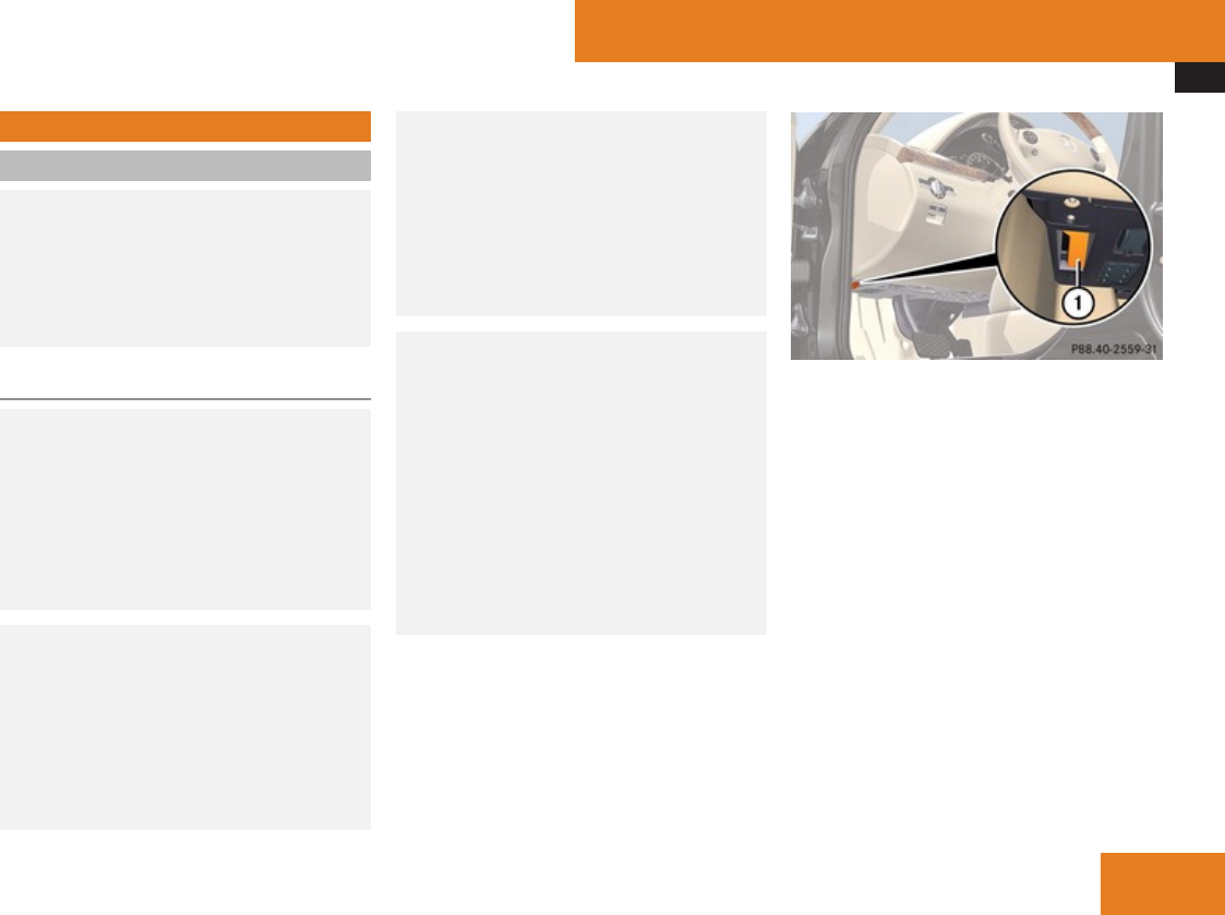
Engine compartment
443
Engine compartment
Hood
GWarning!
Do not pull the release lever while the
vehicle is in motion. Otherwise the hood
could be forced open by passing air flow.
This could cause the hood to come loose
and injure you and/or others.
Opening
GWarning!
If you see flames or smoke coming from the
engine compartment, or if the coolant
temperature gauge indicates that the
engine is overheated, do not open the hood.
Move away from vehicle and do not open
the hood until the engine has cooled. If
necessary, call the fire department.
GWarning!
You could be injured when the hood is open
– even when the engine is turned off.
Parts of the engine can become very hot.
To prevent burns, let the engine cool off
completely before touching any
components on the vehicle. Comply with all
relevant safety precautions.
GWarning!
To help prevent personal injury, stay clear
of moving parts when the hood is open and
the engine is running.
The radiator fan may continue to run for
approximately 30 seconds or may even
restart after the engine has been turned off.
Stay clear of fan blades.
GWarning!
The engine is equipped with a transistorized
ignition system. Because of the high
voltage it is dangerous to touch any
components (ignition coils, spark plug
sockets, diagnostic socket) of the ignition
system
Rwith the engine running
Rwhile starting the engine
Rwhen the ignition is switched on and the
engine is turned manually
1Hood lock release lever
XPull release lever 1.
The hood is unlocked.
! To avoid damage to the windshield wipers
or hood, never open the hood if the wiper
arms are folded forward away from the
windshield.
Operation
Z
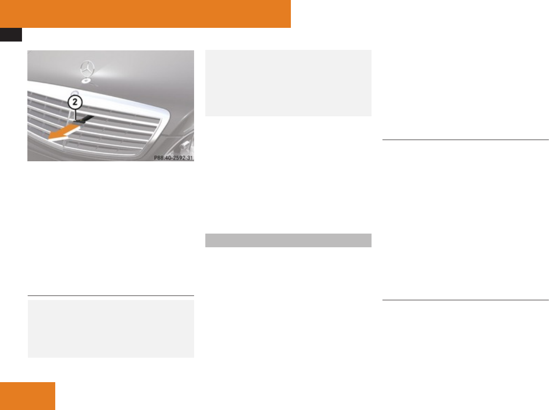
Engine compartment
444
2Handle
! To avoid damage to the handle never pull
up the hood on the handle.
XPull handle 2 to its stop out of radiator
grille.
XPull up on hood.
The hood will be automatically held open at
shoulder height by gas-filled struts.
Closing
GWarning!
When closing the hood, use extreme
caution not to catch hands or fingers. Be
careful that you do not close the hood on
anyone.
Make sure the hood is securely engaged
before driving off. Do not continue driving
if the hood can no longer engage after an
accident, for example. The hood could
otherwise come loose while the vehicle is
in motion and injure you and/or others.
XLet the hood drop from a height of
approximately 1 ft (30 cm).
XCheck to make sure the hood is fully
closed.
If you can raise the hood at a point above
the headlamps, then it is not properly
closed. Open it again and let it drop with
somewhat greater force.
Engine oil
The amount of oil your engine needs will
depend on a number of factors, including
driving style. Increased oil consumption can
occur when the vehicle is new or the vehicle
is driven frequently at higher engine speeds.
Engine oil consumption checks should only
be made after the vehicle break-in period.
! Do not use any special lubricant additives,
as these may damage the drive assemblies.
Using special additives not approved by
Mercedes-Benz may cause damage not
covered by the Mercedes-Benz Limited
Warranty.
For further information contact an
authorized Mercedes-Benz Center.
Notes on checking engine oil level
When checking the oil level
Rthe vehicle must be parked on level ground
Rwith the engine at operating temperature,
the vehicle must have been stationary for
at least 5 minutes with the engine turned
off
Rwith the engine not at operating
temperature, the vehicle must have been
stationary for at least 30 minutes with the
engine turned off
Checking engine oil level with the oil
dipstick
On the S 450 4MATIC, S 550 and S 63 AMG,
you can check the engine oil level with the oil
dipstick.
XOpen the hood (Y page 443).
Operation
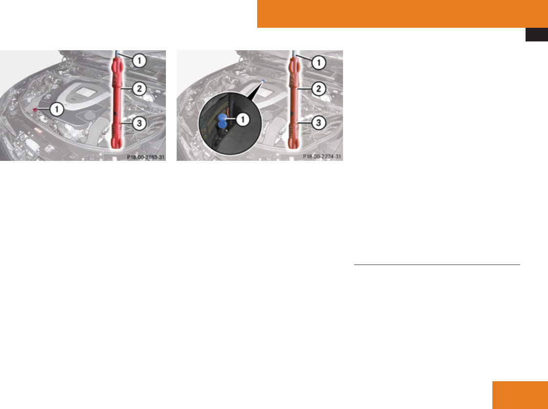
Engine compartment
445
S 550 and S 63 AMG
1Oil dipstick
2Upper (max) mark
3Lower (min) mark
S 450 4MATIC and S 550 4MATIC
1Oil dipstick
2Upper (max) mark
3Lower (min) mark
XPull out oil dipstick 1.
XWipe oil dipstick 1 clean.
XFully insert oil dipstick 1 into the dipstick
guide tube.
XPull out oil dipstick 1 again after
approximately 3 seconds to obtain
accurate reading.
The oil level is correct when it is between
lower (min) mark 3 and upper (max) mark
2 of oil dipstick 1.
iS 450 4MATIC, S 550 and S 550 4MATIC:
The filling quantity between the upper and
lower marks on the oil dipstick is
approximately 2.1 US qt. (2.0 l).
iS 63 AMG only:
The filling quantity between the upper and
lower marks on the oil dipstick is
approximately 1.6 US qt. (1.5 l).
XIf necessary, add engine oil.
For more information on engine oil, see
“Fuels, coolants, lubricants
etc.” (Y page 603).
For information on messages in the
multifunction display concerning engine oil,
see the “Practical hints” section
(Y page 537).
Checking engine oil level with the
control system
On the S 600 and S 65 AMG, you can check
the engine oil level with the control system.
iThe menu overview can be found on
(Y page 240).
XSwitch on the ignition.
XPress ( or & to select the Service
menu.
Operation
Z

Engine compartment
446
XPress $ or % to select Engine Oil
Level.
XPress #.
The following message appears in the
multifunction display:
Measuring
Engine Oil Level
Accurate Only
When Vehicle Is Level
One of the following messages will
subsequently appear in the multifunction
display:
REngine Oil Level
OK
RAdd 1.0 qts. Engine Oil
At Next Refueling
(Canada: 1.0 l)
RAdd 1.5 qts. Engine Oil
At Next Refueling
(Canada: 1.5 l)
RAdd 2.0 qts. Engine Oil
At Next Refueling
(Canada: 2.0 l)
iIf you want to interrupt the checking
procedure, press button L on the
multifunction steering wheel.
XIf necessary, add engine oil.
For more information on engine oil, see
“Fuels, coolants, lubricants
etc.” (Y page 603).
Other display messages
If the ignition is not switched on, the following
message appears in the multifunction
display:
For Engine Oil Level
Ignition Must be On
XSwitch on the ignition.
If you see the message:
Need More Time
to Check
Engine Oil Level
XIf the engine is at operating temperature,
wait 5 minutes before repeating check
procedure.
XIf the engine is not at operating
temperature yet, you must wait 30 minutes
before checking oil.
If you see the message:
Engine Oil Level
Not Measurable
With Running Engine
XTurn off the engine.
XIf the engine is at operating temperature,
wait 5 minutes before checking oil.
XIf the engine is not at operating
temperature yet, you must wait 30 minutes
before checking oil.
If there is excess engine oil with the engine at
normal operating temperature, the following
message appears in the multifunction
display:
Reduce
Engine Oil Level
XHave excess oil siphoned or drained off.
Contact an authorized Mercedes-Benz
Center.
! Excess oil must be siphoned or drained
off. It could cause damage to the engine
and emission control system not covered
by the Mercedes-Benz Limited Warranty.
For information on messages in the
multifunction display concerning engine oil,
see the “Practical hints” section
(Y page 537).
Adding engine oil
! Only use approved engine oils and oil
filters required for vehicles with
Operation
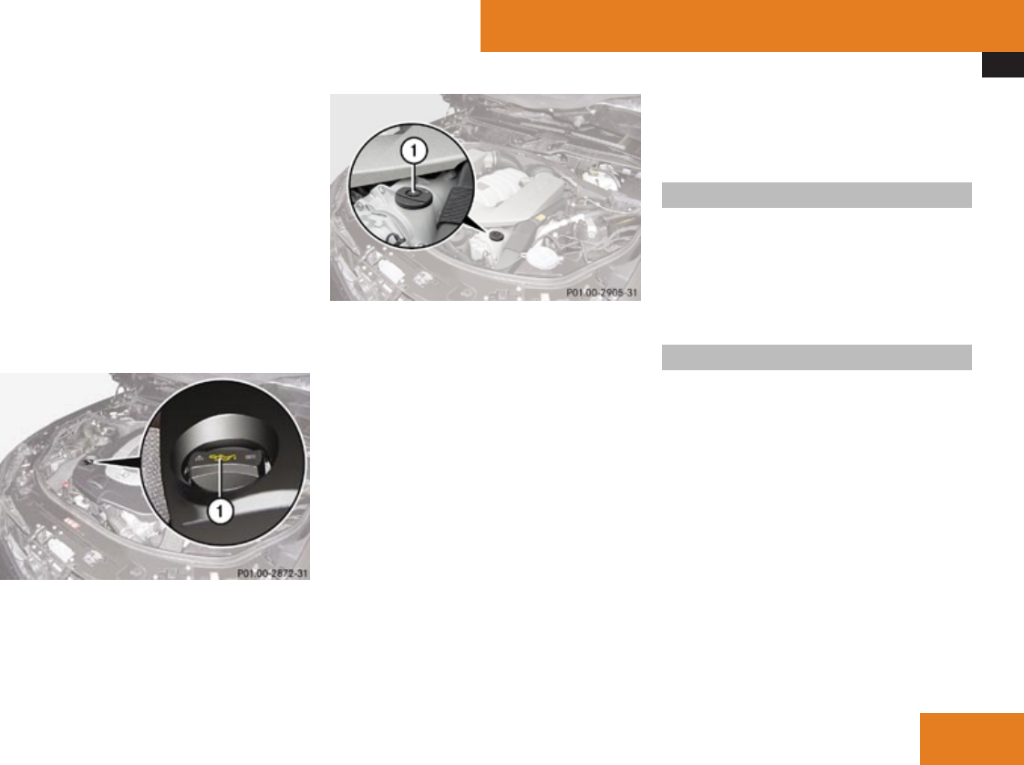
Engine compartment
447
Maintenance System. For a listing of
approved engine oils and oil filters, contact
an authorized Mercedes-Benz Center or
visit www.mbusa.com (USA only).
Using engine oils and oil filters of
specification other than those expressly
required for the Maintenance System, or
changing of oil and oil filter at change
intervals longer than those called for by the
Maintenance System will result in engine or
emission control system damage not
covered by the Mercedes-Benz Limited
Warranty.
Example illustration S 550
1Filler cap
S 63 AMG
1Filler cap
XUnscrew filler cap 1 from filler neck.
XAdd engine oil as required. Be careful not
to overfill with oil.
Be careful not to spill any oil when adding.
Avoid environmental damage caused by oil
entering the ground or water.
! Excess oil must be siphoned or drained
off. It could cause damage to the engine
and emission control system not covered
by the Mercedes-Benz Limited Warranty.
XScrew filler cap 1 back on filler neck.
For more information on engine oil, see the
“Technical data” section (Y page 603) and
(Y page 606).
Transmission fluid level
The transmission fluid level does not need to
be checked. If you notice transmission fluid
loss or gearshifting malfunctions, have an
authorized Mercedes-Benz Center check the
transmission.
Active Body Control (ABC) fluid level
Regular fluid level check is not required. If you
notice fluid leaks or malfunction messages in
the multifunction display, have an authorized
Mercedes-Benz Center check the ABC
system.
Operation
Z
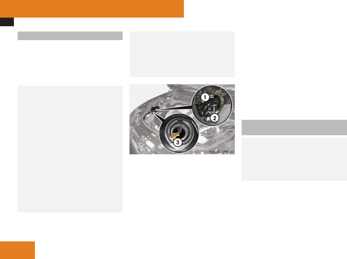
Engine compartment
448
Coolant level
The engine coolant is a mixture of water and
anticorrosion/antifreeze.
When checking the coolant level, the vehicle
must be parked on level ground, and the
coolant temperature must be below 158‡
(70†).
GWarning!
In order to avoid any potentially serious
burns:
RUse extreme caution when opening the
hood if there are any signs of steam or
coolant leaking from the cooling system,
or if the coolant temperature gauge
indicates that the coolant is overheated.
RDo not remove pressure cap on coolant
reservoir if coolant temperature is above
158‡ (70†). Allow engine to cool down
before removing cap. The coolant
reservoir contains hot fluid and is under
pressure.
RUsing a rag, slowly open the cap
approximately 1/2 turn to relieve excess
pressure. If opened immediately,
scalding hot fluid and steam will be blown
out under pressure.
RDo not spill antifreeze on hot engine
parts. Antifreeze contains ethylene
glycol which may burn if it comes into
contact with hot engine parts.
S 550 (example illustration)
1Cap
2Coolant expansion tank
3Marking bar in the expansion tank
XUsing a rag, turn cap 1 slowly
approximately 1/2 turn counterclockwise
to release any excess pressure.
XContinue turning cap 1 counterclockwise
and remove it.
The coolant level is correct if the level
Rfor cold coolant: reaches marking bar
3 in coolant expansion tank 2
Rfor warm coolant: is approximately 0.6 in
(1.5 cm) higher
XAdd coolant as required.
XReplace and tighten cap 1.
For more information on coolant, see the
“Technical data” section (Y page 605) and
(Y page 609).
Washer system and headlamp
cleaning system
GWarning!
Washer solvent/antifreeze is highly
flammable. Do not spill washer solvent/
antifreeze on hot engine parts, because it
may ignite and burn. You could be seriously
burned.
! Always use washer solvent/antifreeze
where temperatures may fall below
freezing point. Failure to do so could result
in damage to the washer system/fluid
reservoir.
Operation
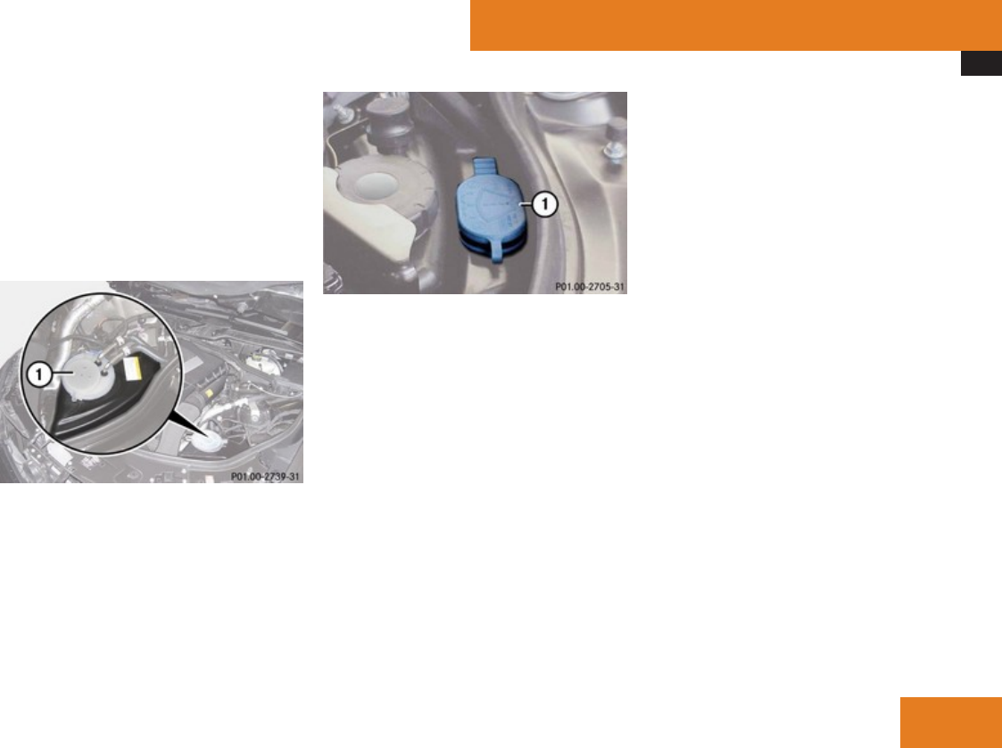
Engine compartment
449
! Only use washer fluid which is suitable for
plastic lenses. Improper washer fluid can
damage the plastic lenses of the
headlamps.
! Do not use distilled or deionized water in
the washer fluid reservoir. Otherwise, the
washer fluid level sensor could be
damaged.
Example illustration S 550 with AIRMATIC
1Cap for washer fluid reservoir
Vehicles with ABC
1Cap for washer fluid reservoir
Fluid for the washer system and the headlamp
cleaning system is supplied from the washer
fluid reservoir.
During all seasons, add MB Windshield
Washer Concentrate “MB SummerFit” to
water. Premix the washer fluid in a suitable
container.
XOpening washer fluid reservoir: Pull tab
of cap 1 upwards.
XRefill the washer fluid reservoir with MB
Windshield Washer Concentrate “MB
SummerFit” and water (or commercially
available premixed washer solvent/
antifreeze, depending on ambient
temperatures) (Y page 612).
XClosing washer fluid reservoir: Press cap
1 onto filler hole until it engages.
For more information, see “Washer system
and headlamp cleaning
system” (Y page 606).
Operation
Z

Tires and wheels
450
Tires and wheels
Safety notes
Contact an authorized Mercedes-Benz Center
for information on tested and recommended
rims and tires for summer and winter
operation. They can also offer advice
concerning tire service and purchase.
GWarning!
Replace rims or tires with the same
designation, manufacturer and type as
shown on the original part. For further
information contact an authorized
Mercedes-Benz Center. If incorrectly sized
rims and tires are mounted, the wheel
brakes or suspension components can be
damaged. Also, the correct operating
clearance of the wheels and the tires may
no longer be correct.
GWarning!
Worn, old tires can cause accidents. If the
tire tread is worn to minimum tread depth,
or if the tires have sustained damage,
replace them.
When replacing rims, only use genuine
Mercedes-Benz wheel bolts specified for
the particular rim type. Failure to do so can
result in the bolts loosening and possibly an
accident.
Retreaded tires are not tested or
recommended by Mercedes-Benz, since
previous damage cannot always be
recognized on retreads. The operating
safety of the vehicle cannot be assured
when such tires are used.
GWarning!
If you feel a sudden significant vibration or
ride disturbance, or you suspect that
possible damage to your vehicle has
occurred, you should turn on the hazard
warning flashers, carefully slow down, and
drive with caution to an area which is a safe
distance from the road.
Inspect the tires and the vehicle underbody
for possible damage. If the vehicle or tires
appear unsafe, have the vehicle towed to
the nearest authorized Mercedes-Benz
Center or tire dealer for repairs.
GWarning!
Do not drive with a flat tire. A flat tire affects
the ability to steer or brake the vehicle. You
could lose control of the vehicle. Continued
driving with a flat tire or driving at high
speed with a flat tire will cause excessive
heat build-up and possibly a fire.
Important guidelines
ROnly use sets of tires and rims of the same
type and make.
RTires must be of the correct size for the rim.
RBreak in new tires for approximately
60 miles (100 km) at moderate speeds.
RRegularly check the tires and rims for
damage. Dented or bent rims can cause tire
inflation pressure loss and damage to the
tire beads.
RIf vehicle is heavily loaded, check tire
inflation pressure and correct as required.
RDo not allow your tires to wear down too
far. Adhesion properties on wet roads are
sharply reduced at tread depths of less
than 1/8 in (3 mm).
RWhen replacing individual tires, you should
mount new tires on the front wheels first
(on vehicles with same-sized wheels all
around).
Operation

Tires and wheels
451
Tire care and maintenance
GWarning!
Regularly check the tires for damage.
Damaged tires can cause tire inflation
pressure loss. As a result, you could lose
control of your vehicle.
Worn, old tires can cause accidents. If the
tire tread is worn to minimum tread depth,
or if the tires have sustained damage,
replace them.
Check the tire inflation pressure at least every
other week. For more information on
checking tire inflation pressure, see
“Recommended tire inflation
pressure” (Y page 456).
Tire inspection
Every time you check the tire inflation
pressure, you should also inspect your tires
for the following:
Rexcessive treadwear (Y page 451)
Rcord or fabric showing through the tire’s
rubber
Rbumps, bulges, cuts, cracks or splits in the
tread or side of the tire
Replace the tire if you find any of the above
conditions.
Make sure you also inspect the spare tire
periodically for condition and inflation. Spare
tires will age and become worn over time even
if never used, and thus should be inspected
and replaced when necessary.
Life of tire
GWarning!
Tires and spare tire should be replaced
after 6 years, regardless of the remaining
tread.
The service life of a tire is dependent upon
varying factors including but not limited to:
RDriving style
RTire inflation pressure
RDistance driven
Tread depth
GWarning!
Although the applicable federal motor
vehicle safety laws consider a tire to be
worn when the treadwear indicators (TWI)
become visible at approximately 1/16 in
(1.6 mm), we recommend that you do not
allow your tires to wear down to that level.
As tread depth approaches 1/8 in (3 mm),
the adhesion properties on a wet road are
sharply reduced.
Depending upon the weather and/or road
surface (conditions), the tire traction varies
widely.
Do not allow your tires to wear down too far.
Adhesion properties on wet roads are sharply
reduced at tread depths of less than 1/8 in
(3 mm).
Treadwear indicators (TWI) are required by
law. These indicators are located in six places
on the tread circumference and become
visible at a tread depth of approximately
1/16 in (1.6 mm), at which point the tire is
considered worn and should be replaced.
The recommended minimum tire tread depth
for summer tires is 1/8 in (3 mm). The
recommended minimum tire tread depth for
winter tires is 1/6 in (4 mm).
Operation
Z
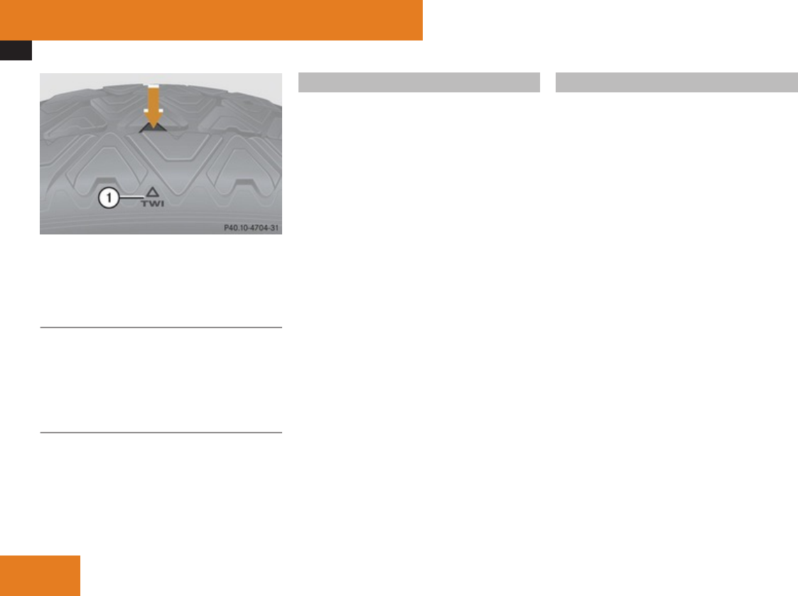
Tires and wheels
452
1TWI (Tread Wear Indicator)
The treadwear indicator appears as a solid
band across the tread.
Storing tires
! Keep unmounted tires in a cool, dry place
with as little exposure to light as possible.
Protect tires from contact with oil, grease
and fuels.
Cleaning tires
! Never use a round nozzle to power wash
tires. The intense jet of water can result in
damage to the tire.
Always replace a damaged tire.
Direction of rotation
Unidirectional tires offer added advantages,
such as better hydroplaning performance. To
benefit, however, you must make sure the
tires rotate in the direction specified.
An arrow on the sidewall indicates the
intended direction of rotation (spinning) of
the tire.
Spare wheels may be mounted against the
direction of rotation (spinning) even with a
unidirectional tire for temporary use only until
the regular drive wheel has been repaired or
replaced. Always observe and follow
applicable temporary use restrictions and
speed limitations indicated on the spare
wheel.
Loading the vehicle
Two labels on your vehicle show how much
weight it may properly carry.
(1) The Tire and Loading Information placard
can be found on the driver’s door
B-pillar. This placard tells you important
information about the number of people
that can be in the vehicle and the total
weight that can be carried in the vehicle.
It also contains information on the proper
size and recommended tire inflation
pressures for the original equipment tires
on your vehicle.
(2) The certification label, also found on the
driver’s door B-pillar. It tells you about the
gross weight capacity of your vehicle,
called the Gross Vehicle Weight Rating
(GVWR). The GVWR includes the weight
of the vehicle, all occupants, fuel and
cargo. The certification label also tells
you about the front and rear axle weight
capacity, called the Gross Axle Weight
Rating (GAWR).
The GAWR is the total allowable weight
that can be carried by a single axle (front
or rear). Never exceed the GVWR or
GAWR for either the front axle or rear
axle.
Operation
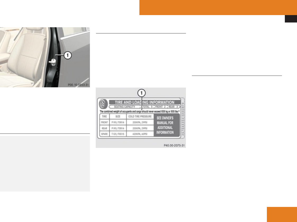
Tires and wheels
453
1Driver’s door B-pillar
Following is a discussion on how to work with
the information contained on the Tire and
Loading Information placard with regards to
loading your vehicle.
Tire and Loading Information
GWarning!
Do not overload the tires by exceeding the
specified load limit as indicated on the Tire
and Loading Information placard on the
driver’s door B-pillar. Overloading the tires
can overheat them, possibly causing a
blowout. Overloading the tires can also
result in handling or steering problems, or
brake failure.
Tire and Loading Information placard
iData shown on Tire and Loading
Information placard example are for
illustration purposes only. Load limit data
are specific to each vehicle and may vary
from data shown in the following
illustration. Refer to Tire and Loading
Information placard on vehicle for actual
data specific to your vehicle.
1Load limit information on the Tire and
Loading Information placard
The Tire and Loading Information placard
showing the load limit information is located
on the driver’s door B-pillar (Y page 453).
XLocate the statement “The combined
weight of occupants and cargo should
never exceed XXX kilograms or XXX lbs.”
on the Tire and Loading Information
placard.
The combined weight of all occupants,
cargo/luggage and trailer tongue load (if
applicable) should never exceed the weight
referenced in that statement.
Seating capacity
The seating capacity gives you important
information on the number of occupants that
can be in the vehicle. Observe front and rear
seating capacity. The Tire and Loading
Information placard showing the seating
capacity is located on the driver’s door
B-pillar (Y page 453).
iData shown on Tire and Loading
Information placard example are for
illustration purposes only. Seating capacity
data are specific to each vehicle and may
vary from data shown in the following
illustration. Refer to Tire and Loading
Information placard on vehicle for actual
data specific to your vehicle.
Operation
Z
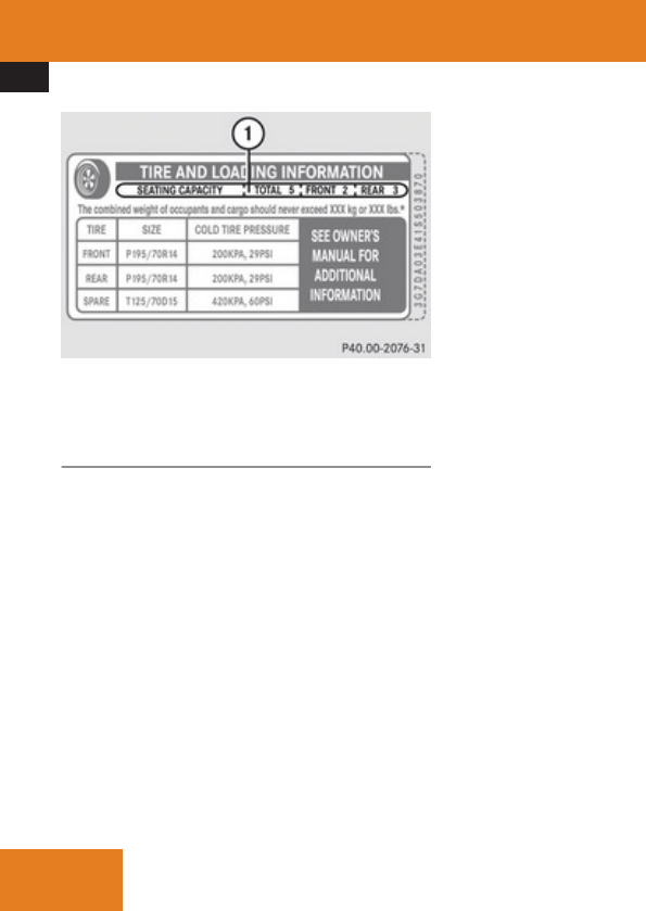
Tires and wheels
454
1Seating capacity information on the Tire
and Loading Information placard
Steps for determining correct load limit
The following steps have been developed as
required of all manufacturers under Title 49,
Code of U.S. Federal Regulations, Part 575
pursuant to the “National Traffic and Motor
Vehicle Safety Act of 1966”.
XStep 1: Locate the statement “The
combined weight of occupants and cargo
should never exceed XXX kg or XXX lbs.”
on your vehicle’s Tire and Loading
Information placard.
XStep 2: Determine the combined weight of
the driver and passengers that will be riding
in your vehicle.
XStep 3: Subtract the combined weight of
the driver and passengers from
XXX kilograms or XXX lbs.
XStep 4: The resulting figure equals the
available amount of cargo and luggage load
capacity. For example, if the “XXX” amount
equals 1 400 lbs and there will be five
150 lbs passengers in your vehicle, the
amount of available cargo and luggage load
capacity is 650 lbs
(1 400 - 750 (5 x 150) = 650 lbs).
XStep 5: Determine the combined weight of
luggage and cargo being loaded on the
vehicle. That weight may not safely exceed
the available cargo and luggage load
capacity calculated in step 4.
XStep 6 (if applicable): If your vehicle will
be towing a trailer, load from your trailer
will be transferred to your vehicle. Consult
this manual to determine how this reduces
the available cargo and luggage load
capacity of your vehicle (Y page 456).
The following table shows examples on how
to calculate total and cargo load capacities
with varying seating configurations and
number and size of occupants. The following
examples use a load limit of 1 500 lbs. This
is for illustration purposes only. Make sure
you are using the actual load limit for your
vehicle stated on the vehicle’s Tire and
Loading Information placard (Y page 453).
Operation

Tires and wheels
455
Example Combined weight
limit of occupants
and cargo from Tire
and Loading
Information
placard
Number of
occupants
(driver and
passengers)
Seating
configuration
Occupants weight Combined
weight of all
occupants
Available cargo/luggage
and trailer tongue weight
(total load limit from Tire
and Loading Information
placard minus combined
weight of all occupants)
11 500 lbs 5 front: 2
rear: 3
Occupant 1: 150 lbs
Occupant 2: 180 lbs
Occupant 3: 160 lbs
Occupant 4: 140 lbs
Occupant 5: 120 lbs
750 lbs 1 500 lbs - 750 lbs = 750 lbs
21 500 lbs 3 front: 1
rear: 2
Occupant 1: 200 lbs
Occupant 2: 190 lbs
Occupant 3: 150 lbs
540 lbs 1 500 lbs - 540 lbs = 960 lbs
31 500 lbs 1 front: 1 Occupant 1: 150 lbs 150 lbs 1 500 lbs - 150 lbs = 1 350 lbs
The higher the weight of all occupants, the
less cargo and luggage load capacity is
available.
For more information, see “Trailer tongue
load” (Y page 456).
Certification label
Even after careful determination of the
combined weight of all occupants, cargo and
the trailer tongue load (if applicable)
(Y page 456) as to not exceed the
permissible load limit, you must make sure
your vehicle never exceeds the Gross Vehicle
Weight Rating (GVWR) and the Gross Axle
Weight Rating (GAWR) for either the front or
rear axle. You can obtain the GVWR and
GAWR from the certification label. The
certification label can be found on the driver’s
door B-pillar, see the “Technical data” section
(Y page 589).
Gross Vehicle Weight Rating (GVWR): The
total weight of the vehicle, all occupants, all
cargo, and the trailer tongue load (if
applicable) must never exceed the GVWR.
Gross Axle Weight Rating (GAWR): The total
allowable weight that can be carried by a
single axle (front or rear).
To assure that your vehicle does not exceed
the maximum permissible weight limits
(GVWR and GAWR for front and rear axle),
Operation
Z

Tires and wheels
456
have the loaded vehicle (including driver,
passengers and all cargo and, if applicable,
trailer fully loaded) weighed on a suitable
commercial scale.
Trailer tongue load
The tongue load of any trailer is an important
weight to measure because it affects the load
you can carry in your vehicle. If a trailer is
towed, the tongue load must be added to the
weight of all occupants riding and any cargo
you are carrying in the vehicle. The tongue
load typically is 10% of the trailer weight and
everything loaded in it.
Your Mercedes-Benz has been designed
primarily to carry passengers and their cargo.
Mercedes-Benz does not recommend trailer
towing with your vehicle.
Recommended tire inflation pressure
GWarning!
Follow recommended tire inflation
pressures.
Do not underinflate tires. Underinflated
tires wear excessively and/or unevenly,
adversely affect handling and fuel
economy, and are more likely to fail from
being overheated.
Do not overinflate tires. Overinflated tires
can adversely affect handling and ride
comfort, wear unevenly, increase stopping
distance, and result in sudden deflation
(blowout) because they are more likely to
become punctured or damaged by road
debris, potholes etc.
Do not overload the tires by exceeding the
specified load limit as indicated on the Tire
and Loading Information placard on the
driver’s door B-pillar. Overloading the tires
can overheat them, possibly causing a
blowout. Overloading the tires can also
result in handling or steering problems, or
brake failure.
Your vehicle is equipped with the Tire and
Loading Information placard located on the
driver’s door B-pillar (Y page 452).
The tire inflation pressure should be checked
regularly and should only be adjusted on cold
tires. The tires can be considered cold if the
vehicle has been parked for at least 3 hours
or driven less than 1 mile (1.6 km).
Follow recommended cold tire inflation
pressures listed on Tire and Loading
Information placard on the driver’s door
B-pillar.
Keeping the tires properly inflated provides
the best handling, tread life and riding
comfort.
In addition to the Tire and Loading
Information placard on the driver’s door
B-pillar, also consult the tire inflation
pressure label (if available) on the inside of
the filler flap for any additional information
pertaining to special driving situations. For
more information, see “Important notes on
tire inflation pressure” (Y page 457).
iData shown on Tire and Loading
Information placard example are for
illustration purposes only. Tire data are
specific to each vehicle and may vary from
data shown in the following illustration.
Refer to Tire and Loading Information
placard on vehicle for actual data specific
to your vehicle.
Operation
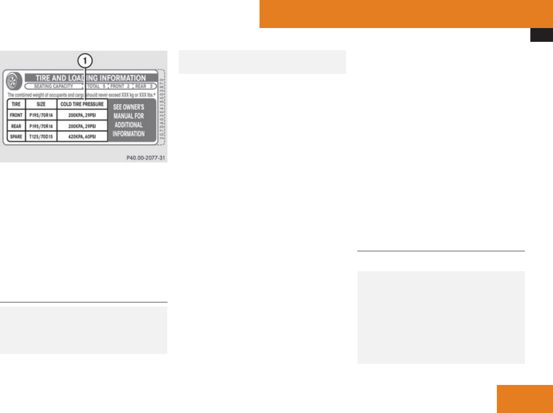
Tires and wheels
457
1Tire and Loading Information placard with
recommended cold tire inflation
pressures
The Tire and Loading Information placard lists
the recommended cold tire inflation
pressures for maximum loaded vehicle
weight. The tire inflation pressures listed
apply to the tires installed as original
equipment.
Important notes on tire inflation
pressure
GWarning!
If the tire inflation pressure drops
repeatedly, check the tires for punctures
from foreign objects and/or whether air is
leaking from the valves or from around the
rim.
Tire temperature and tire inflation pressure
are also increased while driving, depending
on the driving speed and the tire load.
If you will be driving your vehicle at high
speeds of 100 mph (160 km/h) or higher,
where it is legal and conditions allow, consult
the tire inflation pressure label on the inside
of the fuel filler flap (if available) on how to
adjust the cold tire inflation pressure. If you
do not adjust the tire inflation pressure,
excessive heat can build up and result in
sudden tire failure.
If your vehicle is not equipped with the tire
inflation pressure label on the inside of the
fuel filler flap, contact an authorized
Mercedes-Benz Center for proper tire
inflation pressure.
iDriving comfort may be reduced when the
tire inflation pressure is adjusted to the
value for speeds above 100 mph
(160 km/h) as specified on the tire inflation
pressure label located on the inside of the
fuel filler flap.
Make sure to readjust the tire inflation
pressure for normal driving speeds. You
should wait until the tires are cold before
adjusting the tire inflation pressure.
Some vehicles may have supplemental tire
inflation pressure information for vehicle
loads less than the maximum loaded vehicle
condition. If such information is provided, it
can be found on the tire inflation pressure
label located on the inside of the fuel filler
flap.
Tire inflation pressure changes by
approximately 1.5 psi (0.1 bar) per 18‡
(10†) of air temperature change. Keep this
in mind when checking tire inflation pressure
where the temperature is different from the
outside temperature.
Potential problems associated with
underinflated and overinflated tires
Underinflated tires
GWarning!
Follow recommended tire inflation
pressures.
Do not underinflate tires. Underinflated
tires wear excessively and/or unevenly,
adversely affect handling and fuel
economy, and are more likely to fail from
being overheated.
Operation
Z

Tires and wheels
458
Underinflated tires can
Rcause excessive and uneven tire wear
Radversely affect fuel economy
Rlead to tire failure from being overheated
Radversely affect handling characteristics
Overinflated tires
GWarning!
Follow recommended tire inflation
pressures.
Do not overinflate tires. Overinflated tires
can adversely affect handling and ride
comfort, wear unevenly, increase stopping
distance, and result in sudden deflation
(blowout) because they are more likely to
become punctured or damaged by road
debris, potholes etc.
Overinflated tires can
Radversely affect handling characteristics
Rcause uneven tire wear
Rbe more prone to damage from road
hazards
Radversely affect ride comfort
Rincrease stopping distance
Checking tire inflation pressure
Safety notes
GWarning!
Follow recommended tire inflation
pressures.
Do not underinflate tires. Underinflated
tires wear excessively and/or unevenly,
adversely affect handling and fuel
economy, and are more likely to fail from
being overheated.
Do not overinflate tires. Overinflated tires
can adversely affect handling and ride
comfort, wear unevenly, increase stopping
distance, and result in sudden deflation
(blowout) because they are more likely to
become punctured or damaged by road
debris, potholes etc.
Do not overload the tires by exceeding the
specified load limit as indicated on the Tire
and Loading Information placard on the
driver’s door B-pillar. Overloading the tires
can overheat them, possibly causing a
blowout. Overloading the tires can also
result in handling or steering problems, or
brake failure.
Check the tire inflation pressure at least every
other week.
Check and adjust the tire inflation pressure
when the tires are cold. The tires can be
considered cold if the vehicle has been
parked for at least 3 hours or driven less than
1 mile (1.6 km).
If you check the tire inflation pressure when
the tires are warm (the vehicle has been
driven for several miles or sitting less than
3 hours), the reading will be approximately
4 psi (0.3 bar) higher than the cold reading.
This is normal. Do not let air out to match the
specified cold tire inflation pressure.
Otherwise, the tire will be underinflated.
Checking tire inflation pressure
manually
Follow the steps below to achieve correct tire
inflation pressure:
XRemove the cap from the valve on one tire.
XFirmly press a tire gauge onto the valve.
XRead the tire inflation pressure on the tire
gauge and check against the
recommended tire inflation pressure on the
Tire and Loading Information placard on the
driver’s door B-pillar (Y page 453). If
necessary, add air to achieve the
recommended tire inflation pressure.
XIf you have overfilled the tire, release tire
inflation pressure by pushing the metal
Operation

Tires and wheels
459
stem of the valve with e.g. a tip of a pen.
Then recheck the tire inflation pressure
with the tire gauge.
XInstall the valve cap.
XRepeat this procedure for each tire.
Advanced Tire Pressure Monitoring
System (Advanced TPMS)
Your vehicle is equipped with the Advanced
Tire Pressure Monitoring System (Advanced
TPMS). It measures the tire inflation pressure
in the vehicle’s tires and issue warnings in
case of pressure loss in one or more of the
tires.
The TPMS is equipped with a combination low
tire pressure/ TPMS malfunction telltale
(USA) or a low tire pressure telltale (Canada)
in the instrument cluster. Depending on how
the telltale illuminates, it indicates a low tire
pressure condition or a malfunction in the
TPMS system itself:
RIf the telltale illuminates continuously, one
or more of your tires is significantly
underinflated. There is no malfunction in
the TPMS.
RUSA only: If the telltale flashes for 60
seconds and then stays illuminated, the
TPMS system itself is not operating
properly.
The TPMS only functions on wheels that are
equipped with the proper electronic sensors.
GWarning!
The TPMS does not indicate a warning for
wrongly selected inflation pressures.
Always adjust tire inflation pressure
according to the Tire and Loading
Information placard or, if available, on the
supplemental tire inflation pressure
information on the inside of the fuel filler
flap.
The TPMS is not able to issue a warning due
to a sudden dramatic loss of pressure (e.g.
tire blowout caused by a foreign object). In
this case bring the vehicle to a halt by
carefully applying the brakes and avoiding
abrupt steering maneuvers.
GWarning!
Each tire, including the spare (if provided),
should be checked every other week when
cold and inflated to the inflation pressure
recommended by the vehicle manufacturer
on the Tire and Loading Information placard
on the driver’s door B-pillar or, if available,
the tire inflation pressure label on the inside
of the fuel filler flap. If your vehicle has tires
of a different size than the size indicated on
the vehicle placard or the tire inflation
pressure label, you should determine the
proper tire inflation pressure for those tires.
As an added safety feature, your vehicle has
been equipped with a tire pressure
monitoring system (TPMS) that illuminates
a low tire pressure telltale when one or
more of your tires are significantly
underinflated. Accordingly, when the low
tire pressure telltale illuminates, you should
stop and check your tires as soon as
possible, and inflate them to the proper
pressure. Driving on a significantly
underinflated tire causes the tire to
overheat and can lead to tire failure.
Underinflation also reduces fuel efficiency
and tire tread life, and may affect the
vehicle’s handling and stopping ability.
Please note that the TPMS is not a
substitute for proper tire maintenance, and
it is the driver’s responsibility to maintain
correct tire pressure, even if underinflation
has not reached the level to trigger
illumination of the TPMS low tire pressure
telltale.
USA only:
Operation
Z
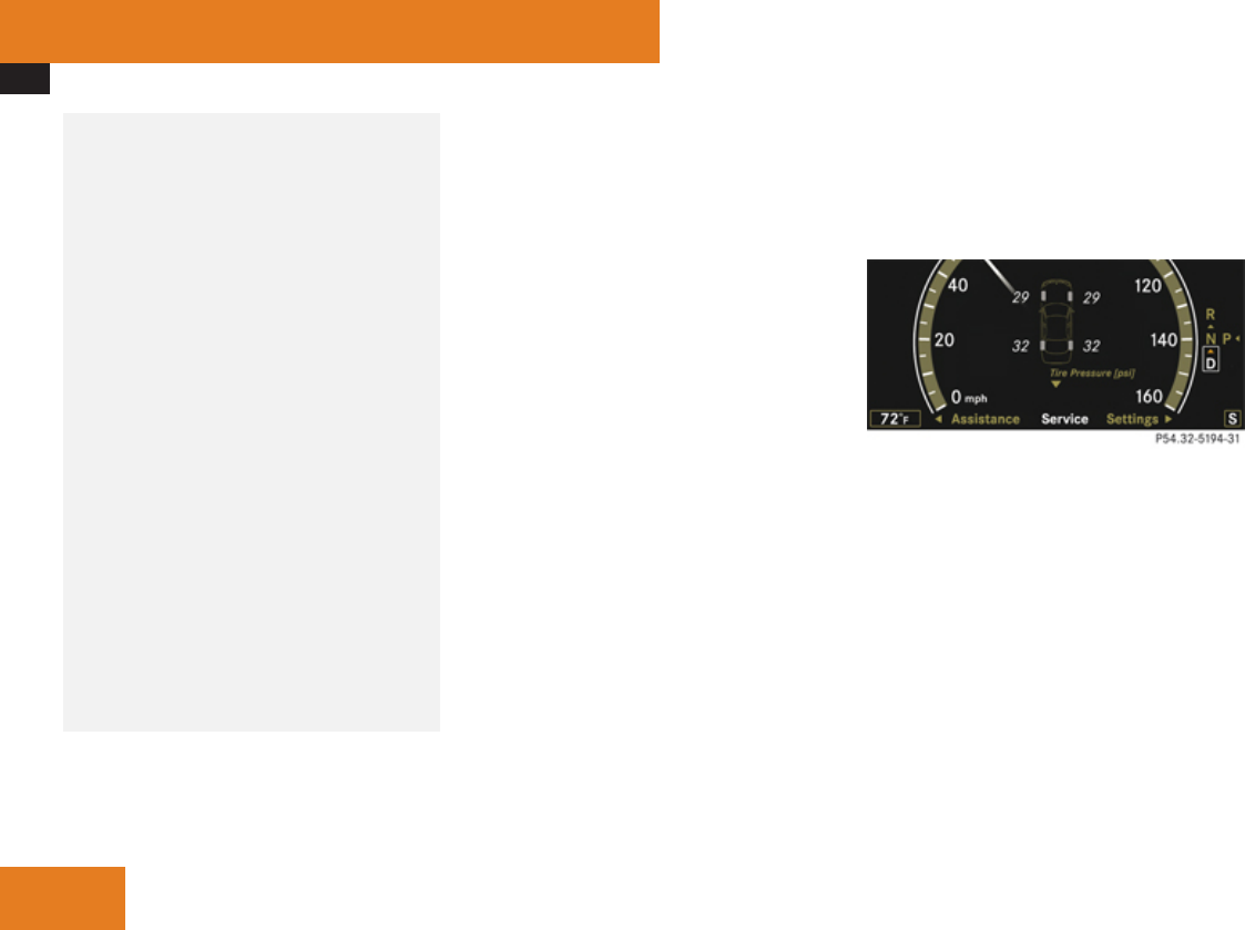
Tires and wheels
460
Your vehicle has also been equipped with a
TPMS malfunction indicator to indicate
when the system is not operating properly.
The TPMS malfunction indicator is
combined with the low tire pressure
telltale. When the system detects a
malfunction, the telltale will flash for
approximately 1 minute and then remain
continuously illuminated. This sequence
will continue upon subsequent vehicle
start-ups as long as the malfunction exists.
When the malfunction indicator is
illuminated, the system may not be able to
detect or signal low tire pressure as
intended.
TPMS malfunctions may occur for a variety
of reasons, including the installation of
replacement or alternate tires or wheels on
the vehicle that prevent the TPMS from
functioning properly. Always check the
TPMS malfunction telltale after replacing
one or more tires or wheels on your vehicle
to ensure that the replacement or alternate
tires and wheels allow the TPMS to
continue to function properly.
iUSA only:
If a condition causing the TPMS to
malfunction develops, it may take up to
10 minutes for the system to signal a
malfunction using the TPMS telltale
flashing and illumination sequence.
The telltale extinguishes after a few
minutes driving if the malfunction has been
corrected.
Tire pressure inquiries are made using the
multifunction display. The current tire
inflation pressure for each tire appears in the
multifunction display after a few minutes of
driving.
iPossible differences between the
readings of a tire pressure gauge of an air
hose, e.g. gas station equipment, and the
vehicle’s control system can occur. The tire
pressure displayed by the control system
apply to sea level. In high-altitude
locations, the reading on a tire pressure
gauge will be higher than the reading issued
by the vehicle’s control system. Do not
reduce the tire inflation pressure under
such circumstances.
XSwitch on the ignition.
XPress button ( or & on the
multifunction steering wheel to select the
Service menu (Y page 251).
XPress button $ or% to select Tire
Press..
XPress button #.
The current inflation pressure for each tire
appears in the multifunction display.
When the vehicle has been parked for longer
than 20 minutes, the message Tire
Pressure Displayed After Driving A
Few Minutes appears in the multifunction
display.
iWith a spare wheel mounted, the system
may still indicate the tire inflation pressure
of the removed road wheel for some
minutes. If this happens, keep in mind that
the indicated value where the spare wheel
is mounted does not reflect the actual
spare tire inflation pressure.
iOperating radio transmission equipment
(e.g. wireless headsets, two-way radios) in
Operation
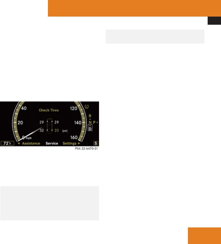
Tires and wheels
461
or near the vehicle could cause the TPMS
to malfunction.
iUSA only:
This device complies with Part 15 of the
FCC Rules. Operation is subject to the
following two conditions:
1. This device may not cause harmful
interference, and
2. this device must accept any
interference received, including
interference that may cause undesired.
Any unauthorized modification to this
device could void the user’s authority to
operate the equipment.
iCanada only:
This device complies with RSS-210 of
Industry Canada. Operation is subject to
the following two conditions:
1. This device may not cause interference,
and
2. this device must accept any
interference received, including
interference that may cause undesired
operation of the device.
Any unauthorized modification to this
device could void the user’s authority to
operate the equipment.
Tire inflation pressure warnings
If the system detects a significant loss of tire
inflation pressure in one or more than one
tire, a message appears in the multifunction
display. In addition, an acoustic warning
sounds and the low tire pressure telltale in the
instrument cluster comes on.
Example illustration
The respective tire and the corresponding tire
inflation pressure are indicated in yellow.
Restarting Advanced TPMS
GWarning!
It is the driver’s responsibility to set the tire
inflation pressure to the recommended
cold tire inflation pressure. Underinflated
tires affect the ability to steer or brake the
vehicle. You might lose control over the
vehicle.
When you restart the TPMS, the system sets
new reference values for each tire.
The TPMS must be restarted when you have
adjusted the tire inflation pressure to a new
level (e.g. because of different load or driving
conditions). The TPMS is then recalibrated to
the current tire inflation pressures.
iCanada only:
The TPMS usually recognizes tire pressure
adjustments and sets new reference values
automatically. You can, however, restart
the TPMS manually as described.
Restart the TPMS after adjusting the tire
inflation pressure to the inflation pressure
recommended for the vehicle operating
condition. Tire pressure should only be
adjusted on cold tires. Observe the
recommended tire inflation pressure on the
Tire and Loading Information placard on the
driver’s door B-pillar. Some vehicles may have
supplemental tire pressure information for
driving at high speeds or for vehicle loads less
than the maximum loaded vehicle condition.
If such information is provided, it can be
found on the inside of the fuel filler flap.
Operation
Z

Tires and wheels
462
XUsing the Tire and Loading Information
placard on the driver’s door B-pillar
(Y page 453) or, if available, the
supplemental tire inflation pressure
information on the inside of the fuel filler
flap, make sure the tire inflation pressure
of all four tires is correct.
XSwitch on the ignition.
XPress button ( or & on the
multifunction steering wheel to select the
Service menu.
XPress button $ or% on the
multifunction steering wheel to select Tire
Press..
XPress button #.
The current inflation pressure for each tire
appears in the multifunction display or the
following message appears in the
multifunction display:
Tire Pressure
Displayed After Driving
A Few Minutes
XPress button %.
The following message appears in the
multifunction display:
Use Current
Pressures As New
Reference Values
Press 'OK' to Confirm
XPress button #.
The following message appears in the
multifunction display:
Tire Pressure Monitor
Reactivated
After driving a few minutes the system
verifies that the current tire inflation
pressures are within the system’s specified
range. Afterwards the current tire inflation
pressures are accepted as reference values
and then monitored.
XIf you wish to cancel: Press button
L.
X
or
XPress button $ to exit the menu screen.
iWhen the wheel positions have been
changed, the air pressure of a tire may be
displayed for the wrong position
temporarily. After driving for a few minutes,
the air pressure will be shown for the
correct position.
iWith a spare wheel mounted, the system
may still indicate the tire inflation pressure
of the removed road wheel for some
minutes. If this happens, keep in mind that
the indicated value where the spare wheel
is mounted does not reflect the actual
spare tire inflation pressure.
Tire labeling
Besides tire name (sales designation) and
manufacturer name, a number of markings
can be found on a tire.
Following are some explanations for the
markings on your vehicle’s tires:
Operation
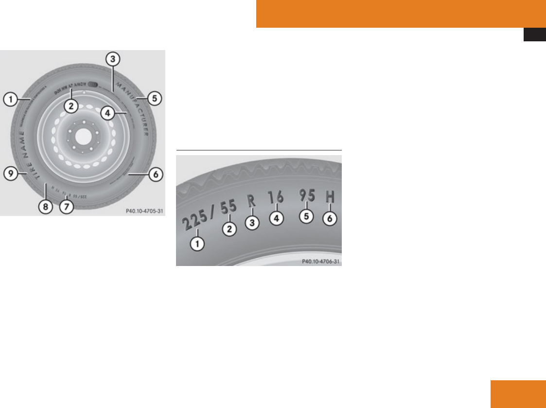
Tires and wheels
463
1Uniform Tire Quality Grading Standards
(Y page 468)
2DOT, Tire Identification Number
(Y page 466)
3Maximum tire load (Y page 467)
4Maximum tire inflation pressure
(Y page 467)
5Manufacturer
6Tire ply material (Y page 469)
7Tire size designation, load and speed
rating (Y page 463)
8Load identification (Y page 466)
9Tire name
iFor illustration purposes only. Actual data
on tires are specific to each vehicle and
may vary from data shown in above
illustration.
For more information, see “Rims and
tires” (Y page 594).
Tire size designation, load and speed
rating
1Tire width
2Aspect ratio in %
3Radial tire code
4Rim diameter
5Tire load rating
6Tire speed rating
iFor illustration purposes only. Actual data
on tires are specific to each vehicle and
may vary from data shown in above
illustration.
General: Depending on the design standards
used, the tire size molded into the sidewall
may have no letter or a letter preceding the
tire size designation.
No letter preceding the size designation (as
illustrated above): Passenger car tire based
on European design standards.
Letter “P” preceding the size designation:
Passenger car tire based on U.S. design
standards.
Letter “LT” preceding the size designation:
Light Truck tire based on U.S. design
standards.
Letter “T” preceding the size designation:
Temporary spare tires which are high
pressure compact spares designed for
temporary emergency use only.
Tire width
Tire width 1 indicates the nominal tire width
in millimeters.
Operation
Z

Tires and wheels
464
Aspect ratio
Aspect ratio 2 is the dimensional
relationship between tire section height and
section width and is expressed in percentage.
The aspect ratio is arrived at by dividing
section height by section width.
Tire code
Tire code 3 indicates the tire construction
type. The “R” stands for radial tire type. Letter
“D” means diagonal or bias ply construction;
letter “B” means belted-bias ply construction.
At the tire manufacturer’s option, any tire
with a speed capability above 149 mph
(240 km/h) can include a “ZR” in the size
designation (for example: 245/40 ZR 18). For
additional information, see “Tire speed
rating” (Y page 464).
Rim diameter
Rim diameter 4 is the diameter of the bead
seat, not the diameter of the rim edge. The
rim diameter is indicated in inches (in).
Tire load rating
GWarning!
The tire load rating must always be at least
half of the GAWR of your vehicle.
Otherwise, tire failure may be the result
which may cause an accident and/or
serious injury to you or others.
Always replace rims and tires with the same
designation, manufacturer and type as
shown on the original part.
GWarning!
Do not overload the tires by exceeding the
specified load limit as indicated on the Tire
and Loading Information placard on the
driver’s door B-pillar. Overloading the tires
can overheat them, possibly causing a
blowout. Overloading the tires can also
result in handling or steering problems, or
brake failure.
Tire load rating 5 is a numerical code
associated with the maximum load a tire can
support.
For example, a load rating of 91 corresponds
to a maximum load of 1356 lb (615 kg) the
tire is designed to support. See also
“Maximum tire load” (Y page 467) where the
maximum load associated with the load index
is indicated in kilograms and lbs.
For additional information on tire load rating,
see “Load identification” (Y page 466).
Tire speed rating
GWarning!
Even when permitted by law, never operate
a vehicle at speeds greater than the
maximum speed rating of the tires.
Exceeding the maximum speed for which
tires are rated can lead to sudden tire
failure, causing loss of vehicle control and
possibly resulting in an accident and/or
serious personal injury and possible death,
for you and for others.
Regardless of the tire speed rating, local
speed limits should be obeyed. Use prudent
driving speeds appropriate to prevailing
conditions.
Tire speed rating 6 indicates the approved
maximum speed for the tire.
Summer tires
Index Speed rating
Q up to 100 mph (160 km/h)
R up to 106 mph (170 km/h)
S up to 112 mph (180 km/h)
T up to 118 mph (190 km/h)
H up to 130 mph (210 km/h)
Operation

Tires and wheels
465
Index Speed rating
V up to 149 mph (240 km/h)
W up to 168 mph (270 km/h)
Y up to 186 mph (300 km/h)
ZR...Y up to 186 mph (300 km/h)
ZR...(..Y) above 186 mph (300 km/h)
ZR above 149 mph (240 km/h)
RAt the tire manufacturer’s option, any tire
with a speed capability above 149 mph
(240 km/h) can include a “ZR” in the size
designation (for example: 245/40 ZR18).
To determine the maximum speed
capability of the tire, the service
description for the tire must be referred to.
The service description is comprised of tire
load rating 5 and tire speed rating 6.
If your tire includes “ZR” in the size
designation and no service description is
given, the tire manufacturer must be
consulted for the maximum speed
capability.
If a service description is given, the speed
capability is limited by the speed symbol in
the service description. Example:
245/40 ZR18 97Y. In this example, “97Y”
is the service description. The letter “Y”
designates the speed rating and the speed
capability of the tire is limited to 186 mph
(300 km/h).
RAny tire with a speed capability above
186 mph (300 km/h) must include a “ZR”
in the size designation AND the service
description must be placed in parenthesis.
Example: 275/40 ZR 18 (99Y). The “(Y)”
speed rating in parenthesis designates the
maximum speed capability of the tire as
being above 186 mph (300 km/h). Consult
the tire manufacturer for the actual
maximum permissible speed of the tire.
All-season and winter tires
Index Speed rating
Q M+S8up to 100 mph (160 km/h)
T M+S8up to 118 mph (190 km/h)
H M+S8up to 130 mph (210 km/h)
V M+S8up to 149 mph (240 km/h)
iNot all M+S rated tires provide special
winter performance. Make sure the tires
you use show M+S and the mountain/
snowflake.marking on the tire
sidewall. These tires meet specific snow
traction performance requirements of the
Rubber Manufacturers Association (RMA)
and the Rubber Association of Canada
(RAC) and have been designed specifically
for use in snow conditions.
An electronic speed limiter prevents your
vehicle from exceeding a speed of:
R130 mph (210 km/h):
-All models except AMG vehicles
R155 mph (250 km/h):
-S 63 AMG
-S 65 AMG
R186 mph (300 km/h):
-S 63 AMG (Performance Package)
-S 63 AMG with increased top speed
-S 65 AMG with increased top speed
The factory equipped tires on your vehicle
may have a tire speed rating above the
8or M+S.for winter tires
Operation
Z
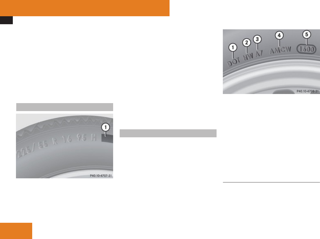
Tires and wheels
466
maximum speed permitted by the electronic
speed limiter.
Make sure your tires have the required tire
speed rating as specified for your vehicle in
the “Technical data” section (Y page 594),
for example when purchasing new tires.
If you are uncertain about the correct reading
of the information given on a tire’s sidewall,
any authorized Mercedes-Benz Center will be
glad to assist you.
Load identification
1Load identification
iFor illustration purposes only. Actual data
on tires are specific to each vehicle and
may vary from data shown in above
illustration.
In addition to tire load rating, special load
identification 1 may be molded into the tire
sidewall following the letter designating the
tire speed rating 6 (Y page 463).
RNo specification given: absence of any text
(like in above example) indicates a
standard load (SL) tire.
RXL or Extra Load: designates an extra load
(or reinforced) tire.
RLight Load: designates a light load tire.
RC, D, E: designates load range associated
with the maximum load a tire can carry at
a specified pressure.
DOT, Tire Identification Number (TIN)
U.S. tire regulations require each new tire
manufacturer or tire retreader to mold a TIN
into or onto a sidewall of each tire produced.
The TIN is a unique identifier which facilitates
efforts by tire manufactures to notify
purchasers in recall situations or other safety
matters concerning tires and gives
purchasers the means to easily identify such
tires.
The TIN is comprised of “Manufacturer’s
identification mark”, “Tire size”, “Tire type
code” and “Date of manufacture”.
1DOT
2Manufacturer’s identification mark
3Tire size
4Tire type code (at the option of the tire
manufacturer)
5Date of manufacture
iFor illustration purposes only. Actual data
on tires are specific to each vehicle and
may vary from data shown in above
illustration.
DOT (Department of Transportation)
Tire branding symbol 1 denotes that the tire
meets requirements of the U.S. Department
of Transportation.
Operation

Tires and wheels
467
Manufacturer’s identification mark
Manufacturer’s identification mark 2
denotes the tire manufacturer.
New tires have a mark with two symbols.
Retreaded tires have a mark with four
symbols. For more information on retreaded
tires, see (Y page 450).
Tire size
Code 3 indicates the tire size.
Tire type code
Tire type code 4 may, at the option of the
manufacturer, be used as a descriptive code
for identifying significant characteristics of
the tire.
Date of manufacture
The date of manufacture 5 identifies the
week and year of manufacture.
The first two figures identify the week,
starting with “01” to represent the first full
week of the calendar year. The second two
figures represent the year.
For example, “3202” represents the 32nd
week of 2002.
Maximum tire load
GWarning!
Do not overload the tires by exceeding the
specified load limit as indicated on the Tire
and Loading Information placard on the
driver’s door B-pillar. Overloading the tires
can overheat them, possibly causing a
blowout. Overloading the tires can also
result in handling or steering problems, or
brake failure.
1Maximum tire load rating
iFor illustration purposes only. Actual data
on tires are specific to each vehicle and
may vary from data shown in above
illustration.
The maximum tire load is the maximum
weight the tires are designed to support.
For more information on tire load rating, see
(Y page 464).
For information on calculating total and cargo
load capacities, see (Y page 454).
Maximum tire inflation pressure
GWarning!
Never exceed the maximum tire inflation
pressure. Follow recommended tire
inflation pressures.
Do not underinflate tires. Underinflated
tires wear excessively and/or unevenly,
adversely affect handling and fuel
economy, and are more likely to fail from
being overheated.
Do not overinflate tires. Overinflated tires
can adversely affect handling and ride
comfort, wear unevenly, increase stopping
distance, and result in sudden deflation
(blowout) because they are more likely to
become punctured or damaged by road
debris, potholes etc.
Operation
Z
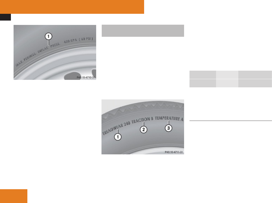
Tires and wheels
468
1Maximum permissible tire inflation
pressure
iFor illustration purposes only. Actual data
on tires are specific to each vehicle and
may vary from data shown in above
illustration.
This is the maximum permissible tire inflation
pressure for the tire.
Always follow the recommended tire inflation
pressure (Y page 456) for proper tire
inflation.
Uniform Tire Quality Grading
Standards
The Uniform Tire Quality Grading is a U.S.
Government requirement designed to give
drivers consistent and reliable information
regarding tire performance. Tire
manufacturers are required to grade tires
based on three performance factors:
treadwear, traction, and temperature
resistance. Although not a Government of
Canada requirement, all tires made for sale in
North America have these grades branded on
the sidewall.
1Treadwear
2Traction
3Temperature resistance
iFor illustration purposes only. Actual data
on tires are specific to each vehicle and
may vary from data shown in above
illustration.
Quality grades can be found, where
applicable, on the tire sidewall between tread
shoulder and maximum section width. For
example:
Treadwear Traction Temperature
200 AA A
All passenger car tires must conform to
federal safety requirements in addition to
these grades.
Treadwear
The treadwear grade is a comparative rating
based on the wear rate of the tire when tested
under controlled conditions on a specified
U.S. Government test course. For example, a
tire graded 150 would wear one and one-half
(1 1/2) times as well on the government
course as a tire graded 100.
The relative performance of tires depends
upon the actual conditions of their use,
however, and may depart significantly from
the norm due to variations in driving habits,
Operation

Tires and wheels
469
service practices and differences in road
characteristics and climate.
Traction
GWarning!
The traction grade assigned to this tire is
based on straight-ahead braking traction
tests, and does not include acceleration,
cornering, hydroplaning, or peak traction
characteristics.
The traction grades, from highest to lowest,
are AA, A, B, and C. Those grades represent
the tire’s ability to stop on wet pavement as
measured under controlled conditions on
specified government test surfaces of asphalt
and concrete. A tire marked C may have poor
traction performance.
GWarning!
If ice has formed on the road, tire traction
will be substantially reduced. Under such
weather conditions, drive, steer and brake
with extreme caution.
The safe speed on a wet, snow covered or icy
road is always lower than on a dry road.
You should pay particular attention to the
condition of the road whenever the outside
temperature is close to the freezing point.
Mercedes-Benz recommends winter tires
(Y page 473) with a minimum tread depth of
approximately 1/6 in (4 mm) on all four wheels
for the winter season to ensure normal
balanced handling characteristics. On
packed snow, they can reduce your stopping
distance compared to summer tires.
Stopping distance, however, is still
considerably greater than when the road is
not covered with snow or ice. Exercise
appropriate caution.
! Avoid spinning of a drive wheel. This may
cause serious damage to the drivetrain
which is not covered by the Mercedes-Benz
Limited Warranty.
Temperature
GWarning!
The temperature grade for this tire is
established for a tire that is properly
inflated and not overloaded. Excessive
speed, underinflation, or excessive loading,
either separately or in combination, can
cause excessive heat build-up and possible
tire failure.
The temperature grades are A (the highest),
B, and C, representing the tire’s resistance to
the generation of heat and its ability to
dissipate heat when tested under controlled
conditions on a specified indoor laboratory
test wheel. Sustained high temperature can
cause the material of the tire to degenerate
and reduce tire life, and excessive
temperature can lead to sudden tire failure.
The grade C corresponds to a level of
performance which all passenger car tires
must meet under the Federal Motor Vehicle
Safety Standard No. 109. Grades B and A
represent higher levels of performance on the
laboratory test wheel than the minimum
required by law.
Tire ply material
1Plies in sidewall
2Plies under tread
Operation
Z

Tires and wheels
470
iFor illustration purposes only. Actual data
on tires are specific to each vehicle and
may vary from data shown in above
illustration.
This marking tells you about the type of cord
and number of plies in the sidewall and under
the tread.
Tire and loading terminology
Accessory weight
The combined weight (in excess of those
standard items which may be replaced) of
automatic transmission, power steering,
power brakes, power windows, power seats,
radio, and heater, to the extent that these
items are available as factory-installed
equipment (whether installed or not).
Air pressure
The amount of air inside the tire pressing
outward on each square inch of the tire. Air
pressure is expressed in pounds per square
inch (psi), or kilopascal (kPa) or bar.
Aspect ratio
Dimensional relationship between tire
section height and section width expressed
in percentage.
Bar
Another metric unit for air pressure. There are
14.5038 pounds per square inch (psi) to
1 bar; there are 100 kilopascals (kPa) to 1 bar.
Bead
The tire bead contains steel wires wrapped by
steel cords that hold the tire onto the rim.
Cold tire inflation pressure
Tire inflation pressure when your vehicle has
been sitting for at least 3 hours or driven no
more than 1 mile (1.6 km).
Curb weight
The weight of a motor vehicle with standard
equipment including the maximum capacity
of fuel, oil, and coolant, and, if so equipped,
air conditioning and additional optional
equipment, but without passengers and
cargo.
DOT (Department of Transportation)
A tire branding symbol which denotes the tire
meets requirements of the U.S. Department
of Transportation.
GAWR (Gross Axle Weight Rating)
The GAWR is the maximum permissible axle
weight. The gross vehicle weight on each axle
must never exceed the GAWR for the front
and rear axle indicated on the certification
label located on the driver’s door B-pillar.
GVW (Gross Vehicle Weight)
The GVW comprises the weight of the vehicle
including fuel, tools, spare wheel, installed
accessories, passengers and cargo and, if
applicable, trailer tongue load. The GVW must
never exceed the GVWR indicated on the
certification label located on the driver’s door
B-pillar.
GVWR (Gross Vehicle Weight Rating)
This is the maximum permissible vehicle
weight of the fully loaded vehicle (weight of
the vehicle including all options, passengers,
fuel, and cargo and, if applicable, trailer
Operation

Tires and wheels
471
tongue load). It is indicated on certification
label located on the driver’s door B-pillar.
Kilopascal (kPa)
The metric unit for air pressure. There are
6.9 kPa to 1 psi; another metric unit for air
pressure is bar. There are 100 kilopascals
(kPa) to 1 bar.
Maximum load rating
The maximum load in kilograms and pounds
that can be carried by the tire.
Maximum loaded vehicle weight
The sum of curb weight, accessory weight,
total load limit, and production options
weight.
Maximum permissible tire inflation
pressure
This number is the greatest amount of air
pressure that should ever be put in the tire.
Normal occupant weight
The number of occupants the vehicle is
designed to seat, multiplied by 68 kilograms
(150 lb).
Occupant distribution
The distribution of occupants in a vehicle at
their designated seating positions.
Production options weight
The combined weight of those installed
regular production options weighing over
5 lbs (2.3 kilograms) in excess of those
standard items which they replace, not
previously considered in curb weight or
accessory weight, including heavy duty
brakes, ride levelers, roof rack, heavy duty
battery, and special trim.
PSI (Pounds per square inch)
A standard unit of measure for air pressure.
Recommended tire inflation pressure
The recommended tire inflation pressure for
normal driving conditions is listed on the Tire
and Loading Information placard located on
the driver’s door B-pillar and provides best
handling, tread life and riding comfort. If so
equipped, supplemental information
pertaining to special driving situations can be
found on the tire inflation pressure label on
the inside of the fuel filler flap.
Rim
A metal support for a tire or a tire and tube
assembly upon which the tire beads are
seated.
Sidewall
The portion of a tire between the tread and
the bead.
TIN (Tire Identification Number)
Unique identifier which facilitates efforts by
tire manufacturers to notify purchasers in
recall situations or other safety matters
concerning tires and gives purchasers the
means to easily identify such tires. The TIN is
comprised of “Manufacturer’s identification
mark”, “Tire size”, “Tire type code” and “Date
of manufacture”.
Operation
Z

Tires and wheels
472
Tire load rating
Numerical code associated with the
maximum load a tire can support.
Tire ply composition and material used
This indicates the number of plies or the
number of layers of rubber-coated fabric in
the tire tread and sidewall. Tire
manufacturers also must indicate the ply
materials in the tire and sidewall, which
include steel, nylon, polyester, and others.
Tire speed rating
Part of tire designation; indicates the speed
range for which a tire is approved.
Total load limit
Rated cargo and luggage load plus
68 kilograms (150 lb) times the vehicle’s
designated seating capacity.
Traction
Force exerted by the vehicle on the road via
the tires. The amount of grip provided.
Tread
The portion of a tire that comes into contact
with the road.
Treadwear indicators
Narrow bands, sometimes called “wear bars”
that show across the tread of a tire when only
1/16 in (1.6 mm) of tread remains.
Uniform Tire Quality Grading Standards
A tire information system that provides
consumers with ratings for a tire’s traction,
temperature and treadwear. Ratings are
determined by tire manufacturers using U.S.
government testing procedures. The ratings
are molded into the sidewall of the tire.
Vehicle maximum load on the tire
Load on an individual tire that is determined
by distributing to each axle its share of the
maximum loaded vehicle weight and dividing
it by two.
Rotating tires
GWarning!
Rotate front and rear wheels only if the tires
are of the same dimension.
If your vehicle is equipped with mixed-size
tires (different tire dimensions front vs.
rear), tire rotation is not possible.
GWarning!
Have the tightening torque checked after
changing a wheel. The wheels could come
loose if they are not tightened to a torque
of 110 lb-ft (150 Nm).
Only use genuine Mercedes-Benz wheel
bolts specified for your vehicle’s rims.
Tire rotation can be performed on vehicles
with tires of the same dimension all around.
If your vehicle is equipped with tires of the
same dimension all around, tires can be
rotated, observing a front-to-rear rotation
pattern that will maintain the intended
rotation (spinning) direction of the tire
(Y page 452).
In some cases, such as when your vehicle is
equipped with mixed-size tires (different tire
dimension front vs. rear), tire rotation is not
possible.
Operation

Winter driving
473
If applicable to your vehicle’s tire
configuration, tires can be rotated according
to the tire manufacturer’s recommended
intervals in the tire manufacturer’s warranty
pamphlet located in your vehicle literature
portfolio. If none is available, tires should be
rotated every 3 000 to 6 000 miles (5 000 to
10 000 km), or sooner if necessary, according
to the degree of tire wear. The same rotation
(spinning) direction must be maintained.
Rotate tires before the characteristic tire
wear pattern becomes visible (shoulder wear
on front tires and tread center wear on rear
tires).
Thoroughly clean the mounting face of wheels
and brake disks, i.e. the inner side of the
wheels/tires, during each rotation. Check for
and ensure proper tire inflation pressure.
For information on wheel change, see “Flat
tire” (Y page 571).
Winter driving
General information
Have your vehicle winterized at an authorized
Mercedes-Benz Center.
Winter tires
GWarning!
Winter tires with a tread depth of less than
1/6 in (4 mm) must be replaced. They are
no longer suitable for winter operation.
GWarning!
If you use your spare wheel when winter
tires are fitted on the other wheels, be
aware that the difference in tire
characteristics may very well impair turning
stability and that overall driving stability
may be reduced. Adapt your driving style
accordingly.
Have the spare wheel replaced by regular
road wheel with a winter tire at the nearest
authorized Mercedes-Benz Center.
Always use winter tires at temperatures
below 45‡ (7†) and whenever wintry road
conditions prevail. Not all M+S rated tires
provide special winter performance. Make
sure the tires you use show the mountain/
snowflake.marking on the tire sidewall.
These tires meet specific snow traction
performance requirements of the Rubber
Manufacturers Association (RMA) and the
Rubber Association of Canada (RAC) and
have been designed specifically for use in
snow conditions. Use of winter tires is the
only way to achieve the maximum
effectiveness of your vehicle’s driving safety
systems such as the ABS and the ESP® in
winter operation.
For safe handling, make sure all mounted
winter tires are of the same make and have
the same tread design.
For information on winter tires for your
vehicle model, see the “Technical data”
section (Y page 594).
Always observe the speed rating of the winter
tires installed on your vehicle. If the maximum
speed for which your tires are rated is below
the speed rating of your vehicle, you must
place a notice to this effect where it will be
seen by the driver. Such notices are available
at your tire dealer or any authorized
Mercedes-Benz Center.
Operation
Z

Winter driving
474
Snow chains
! When driving with snow chains, always
select the raised level of the vehicle level
control. Other settings may result in
damage to your vehicle.
! Some tire sizes do not leave adequate
clearance for snow chains. To help avoid
serious damage to your vehicle or tires,
make sure the use of snow chains is
permissible as specified in the “Technical
data” section of this Operator’s Manual.
Snow chains should only be driven on snow-
covered roads at speeds not to exceed
30 mph (50 km/h). Remove chains as soon
as possible when driving on roads without
snow.
Observe the following guidelines when using
snow chains:
RUse of snow chains is not permissible with
all wheel/tire combinations (Y page 594).
RUse snow chains in pairs and on rear
wheels only. Follow the manufacturer’s
mounting instructions.
! If snow chains are mounted to the front
wheels, they may scrape against the body
or axle components. The tires or the vehicle
could be damaged as a result.
ROnly use snow chains that are approved by
Mercedes-Benz. Any authorized Mercedes-
Benz Center will be glad to advise you on
this subject.
RUse of snow chains may be prohibited
depending on location. Always check local
and state laws before installing snow
chains.
RDo not use snow chains on the spare wheel.
iWhen driving with snow chains, you may
wish to switch off the ESP® (Y page 73)
before setting the vehicle in motion. This
will improve the vehicle’s traction.
Winter driving instructions
GWarning!
If the vehicle becomes stuck in snow, make
sure snow is kept clear of the exhaust pipe
and from around the vehicle with the engine
running. Otherwise, deadly carbon
monoxide (CO) gases may enter vehicle
interior resulting in unconsciousness and
death.
To assure sufficient fresh air ventilation,
open a window slightly on the side of the
vehicle not facing the wind.
GWarning!
The outside temperature indicator is not
designed to serve as an ice-warning device
and is therefore unsuitable for that
purpose.
Indicated temperatures just above the
freezing point do not guarantee that the
road surface is free of ice. The road may still
be icy, especially in wooded areas or on
bridges.
GWarning!
On slippery road surfaces, never downshift
in order to obtain braking action. This could
result in drive wheel slip and reduced
Operation

Driving instructions
475
vehicle control. Your vehicle’s ABS will not
prevent this type of loss of control.
The most important rule for slippery or icy
roads is to drive sensibly and to avoid abrupt
acceleration, braking and steering
maneuvers. Do not use the cruise control or
DISTRONIC Plus system under such
conditions.
When the vehicle is in danger of skidding, shift
the automatic transmission to neutral
position N. Try to keep the vehicle under
control by corrective steering action.
iFor information on driving with snow
chains, see “Snow chains” (Y page 474).
Road salts and chemicals can adversely
affect braking efficiency. Increased pedal
force may become necessary to produce the
normal brake effect.
Depressing the brake pedal periodically when
traveling at length on salt-strewn roads can
bring road-salt-impaired braking efficiency
back to normal.
If the vehicle is parked after being driven on
salt-treated roads, the braking efficiency
should be tested as soon as possible after
driving is resumed.
GWarning!
Make sure not to endanger any other road
users when carrying out these braking
maneuvers.
Driving instructions
Drive sensibly – save fuel
To save fuel you should:
RKeep tires at the recommended inflation
pressures.
RRemove unnecessary loads.
RRemove roof rack when not in use.
RAllow engine to warm up under low load
use.
RAvoid frequent acceleration and
deceleration.
RHave all maintenance work performed at
the intervals specified in the Maintenance
Booklet and as required by the
Maintenance system. Contact an
authorized Mercedes-Benz Center.
Fuel consumption is also increased by driving
in cold weather, in stop-and-go traffic, on
short trips and in mountainous areas.
Operation
Z

Driving instructions
476
Drinking and driving
GWarning!
Drinking and driving and/or taking drugs
and driving are very dangerous
combinations. Even a small amount of
alcohol or drugs can affect your reflexes,
perceptions and judgment.
The possibility of a serious or even fatal
accident are greatly increased when you
drink or take drugs and drive.
Do not drink or take drugs and drive or allow
anyone to drive who has been drinking or
taking drugs.
Pedals
GWarning!
Make sure absolutely no objects are
obstructing the pedals’ range of movement.
Keep the driver’s footwell clear of all
obstacles. If there are any floormats or
carpets in the footwell, make sure that the
pedals still have sufficient clearance.
During sudden driving or braking
maneuvers, the objects could get caught
between the pedals. You could then no
longer brake or accelerate. This could lead
to accidents and injury.
Power assistance
GWarning!
There is no power assistance for the
steering and the service brake when the
engine is not running.
Steering and braking requires significantly
more effort and you could lose control of
the vehicle and cause an accident as a
result.
Do not turn off the engine while the vehicle
is in motion.
Brakes
Downhill grades
! When driving down long and steep
grades, relieve the load on the brakes by
shifting into a lower gear to use the
engine’s braking power. This helps prevent
overheating of the brakes and reduces
wear.
When using the engine’s braking power, a
drive wheel may not spin for an extended
period of time, e.g. on slippery road
surfaces. This may cause serious damage
to the drivetrain which is not covered by the
Mercedes-Benz Limited Warranty.
Continuous or hard braking
GWarning!
Resting your foot on the brake pedal will
cause excessive and premature wear of the
brake pads.
It can also result in the brakes overheating,
thereby significantly reducing their
effectiveness. It may not be possible to
stop the vehicle in sufficient time to avoid
an accident.
After hard braking, it is advisable to drive on
for some time, rather than immediately park,
so that the air stream will cool down the
brakes faster.
Wet roads
GWarning!
After driving in heavy rain for some time
without applying the brakes or through
water deep enough to wet brake
components, the first braking action may
be somewhat reduced and increased pedal
pressure may be necessary to obtain
Operation

Driving instructions
477
expected brake effect. Maintain a safe
distance from vehicles in front.
To help prevent brake disk corrosion after
driving on wet or salt-covered roads, it is
advisable to brake the vehicle with
considerable force prior to parking. The heat
generated serves to dry the brakes.
Salt-covered roads
GWarning!
A layer of salt on the brake discs and the
brake linings may cause a delay in the
braking effect, resulting in a significantly
increased braking distance, which could
lead to an accident.
To avoid this danger, you should:
Roccasionally brake carefully when you
are driving on salt-covered roads, so that
any layer of salt that may have built up
on the brake discs and the brake linings
is removed without putting other road
users at risk
Rmaintain a greater distance to the vehicle
ahead and drive with particular care
Rcarefully apply the brakes at the end of a
trip and immediately after commencing a
new trip, so that salt residues are
removed from the brake disc
Brake service
! The brake fluid level in the reservoir may
be too low if the red brake warning lamp in
the instrument cluster comes on while the
engine is running and an acoustic warning
sounds. Observe additional messages in
the multifunction display that may appear.
Brake pad wear or a leak in the system may
be the reason for low brake fluid in the
reservoir.
Have the brake system inspected
immediately. Contact an authorized
Mercedes-Benz Center.
All checks and service work on the brake
system should be carried out by qualified
technicians only. Contact an authorized
Mercedes-Benz Center.
Only install brake pads and use brake fluid
recommended by Mercedes-Benz.
GWarning!
If other than recommended brake pads are
installed, or other than recommended
brake fluid is used, the braking properties
of the vehicle can be degraded to an extent
that safe braking is substantially impaired.
This could result in an accident.
! Vehicles with 4MATIC:
Only conduct operational or performance
tests on a two-axle dynamometer. If such
tests are necessary, contact an authorized
Mercedes-Benz Center. You could
otherwise seriously damage the brake
system or the transfer case which is not
covered by the Mercedes-Benz Limited
Warranty.
! Vehicles with 4MATIC:
Because the ESP® operates automatically,
the engine and ignition must be shut off
(SmartKey in starter switch position 0 or
1 or KEYLESS-GO start/stop button in
position 0 or 1) when the electronic parking
brake is being tested on a brake test
dynamometer.
Active braking action through the ESP®
may otherwise seriously damage the brake
system which is not covered by the
Mercedes-Benz Limited Warranty.
! Vehicles without 4MATIC:
Because the ESP® operates automatically,
the engine and ignition must be shut off
Operation
Z

Driving instructions
478
(SmartKey in starter switch position 0 or
1 or KEYLESS-GO start/stop button in
position 0 or 1) when the electronic parking
brake is being tested on a brake test
dynamometer or when the vehicle is being
towed with one axle raised.
Active braking action through the ESP®
may otherwise seriously damage the brake
system which is not covered by the
Mercedes-Benz Limited Warranty.
If your brake system is normally only
subjected to moderate loads, you should
occasionally test the effectiveness of the
brakes by applying above-normal braking
pressure at higher speeds. This will also
enhance the grip of the brake pads.
GWarning!
Make sure not to endanger any other road
users when carrying out these braking
maneuvers.
Refer to the description of the Brake Assist
System BAS (Y page 70) or BAS Plus
(Y page 70).
High-performance brake system
The high-performance brake system is only
available on S 63 AMG and S 65 AMG.
GWarning!
New vehicle brake pads and discs, and
replacement brake pads and discs may
take several hundred miles of driving until
they provide optimum braking efficiency.
Until that time, you may need to use
increased brake pedal pressure while
braking. Please be aware of this and adjust
your driving and braking accordingly during
this break-in period.
Excessive high-demand braking will cause
correspondingly high brake wear. Please be
attentive to the brake warning lamp in the
instrument cluster and brake condition
messages in the multifunction display.
Especially for high performance driving, it
is important to maintain and have the brake
system checked regularly.
The high-performance brake system is
designed to operate under the extremely high
operating demands required to
accommodate the performance capabilities
of the vehicle.
The brakes may produce a squeaking-type
noise depending on the
Rvehicle speed
Rbrake force applied
Rambient conditions, e.g. temperature and
humidity
As with any brake system, the wear of
individual brake system components such as
brake pads or disks strongly depends on your
driving style and the conditions under which
you operate the vehicle. Thus, a driving style
calling for high-demand braking will cause
your vehicle’s brakes to wear more quickly.
Driving off
Warm up the engine smoothly. Do not place
full load on the engine until the operating
temperature has been reached.
! When driving off on a slippery surface, do
not allow a drive wheel to spin for an
extended period with the ESP® switched
off. Doing so may cause serious damage to
the drivetrain which is not covered by the
Mercedes-Benz Limited Warranty.
! Simultaneously depressing the
accelerator pedal and applying the brakes
Operation

Driving instructions
479
reduces engine performance and causes
premature brake and drivetrain wear which
is not covered by the Mercedes-Benz
Limited Warranty.
Hydroplaning
Depending on the depth of the water layer on
the road, hydroplaning may occur, even at low
speeds and with new tires. In heavy rain or
when conditions indicate possible
hydroplaning:
XReduce vehicle speed.
XAvoid track grooves in the road.
XApply brakes cautiously.
Standing water
! Do not drive through flooded areas.
Before driving through water, determine its
depth.
If you must drive through standing water,
drive slowly to prevent water from entering
the passenger compartment or the engine
compartment. Water in these areas could
cause damage to electrical components or
wiring of the engine or transmission, or
could result in water being ingested by the
engine through the air intake causing
severe internal engine damage. Any such
damage is not covered by the Mercedes-
Benz Limited Warranty.
Driving abroad
If you plan to drive the vehicle outside the U.S.
or Canada, you should request dealer
network information for your destination from
any authorized Mercedes-Benz Center.
Control and operation of radio
transmitter
Safety notes
GWarning!
Please do not forget that your primary
responsibility is to drive the vehicle. A
driver’s attention to the road must always
be his/her primary focus when driving. For
your safety and the safety of others, we
recommend that you pull over to a safe
location and stop before placing or taking
a telephone call.
If you choose to use the telephone9 while
driving, please use the hands-free device
and only use the telephone when road,
weather and traffic conditions permit.
Some jurisdictions prohibit the driver from
using a mobile telephone while driving a
vehicle.
9Observe all legal requirements.
Operation
Z

Driving instructions
480
Only operate the COMAND9 (Cockpit
Management and Data System) if road,
weather and traffic conditions permit.
Otherwise, you may not be able to observe
traffic conditions and could endanger
yourself and others.
Bear in mind that at a speed of just 30 mph
(approximately 50 km/h), your vehicle is
covering a distance of 44 feet
(approximately 14 m) every second.
Telephones and two-way radios
GWarning!
Never operate radio transmitters equipped
with a built-in or attached antenna, such as
a portable telephone or a citizens band unit,
from inside the vehicle while the engine is
running. Doing so could lead to a
malfunction of the vehicle’s electronic
system, possibly resulting in an accident
and/or serious personal injury. Radio
transmitters should only be used inside the
vehicle if they are connected to an antenna
that is installed on the outside of the
vehicle.
Refer to the radio transmitter operation
instructions regarding use of an external
antenna.
Emission control
Certain systems of the engine serve to keep
the toxic components of the exhaust gases
within permissible limits required by law.
These systems will function properly only
when maintained strictly according to factory
specifications. Any adjustments on the
engine should, therefore, be carried out only
by qualified Mercedes-Benz Center
authorized technicians.
Engine adjustments should not be altered in
any way. Moreover, the specified service
procedures must be carried out regularly
according to Mercedes-Benz servicing
requirements. For details refer to the
Maintenance Booklet.
GWarning!
Inhalation of exhaust gas is hazardous to
your health. All exhaust gas contains
carbon monoxide (CO), and inhaling it can
cause unconsciousness and possible
death.
Do not run the engine in confined areas
(such as a garage) which are not properly
ventilated. If you think that exhaust gas
fumes are entering the vehicle while
driving, have the cause determined and
corrected immediately. If you must drive
under these conditions, drive only with at
least one window fully open at all times.
9Observe all legal requirements.
Operation
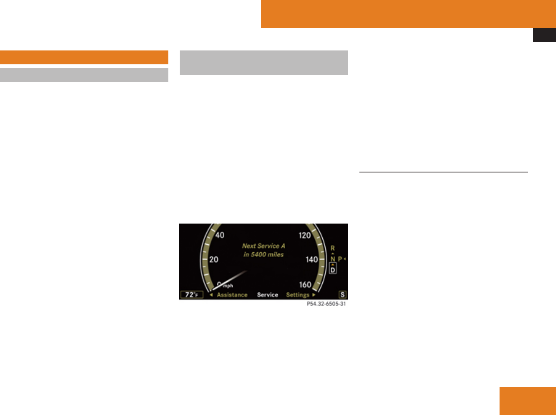
Maintenance
481
Maintenance
Notes
The Maintenance System in your vehicle
tracks the distance driven and the time
elapsed since the last maintenance service,
calculates other maintenance service work
required, and calls for the next maintenance
service accordingly.
We strongly recommend that you have your
vehicle serviced at an authorized Mercedes-
Benz Center, in accordance with the
Maintenance Booklet at the times called for
by the maintenance service indicator.
iFailure to have the vehicle maintained in
accordance with the Maintenance Booklet
and maintenance service indicator at the
designated times/mileage will result in
vehicle damage not covered by the
Mercedes-Benz Limited Warranty.
Maintenance service indicator
message
The maintenance service indicator message
will notify you when the next maintenance
service is due.
Starting approximately 1 month before the
next maintenance service is due, one of the
following messages will appear in the
multifunction display while you are driving or
when you switch on the ignition (example
service A):
Next Service A in XXX miles (km)
Next Service A in XXX days
Service A Due
The maintenance services will be indicated by
showing a service type A through type H in the
multifunction display. Types A through H are
classified based on estimated time needed to
perform the maintenance service, ranging:
from Service A
(approximately 1 hour)
to Service H
(approximately 8 hours)
Refer to Maintenance Booklet for a listing of
maintenance services and intervals they need
to be performed at.
Clearing the maintenance service
indicator message
The maintenance service indicator message
is cleared automatically
Rafter approximately 10 seconds when you
switch on the ignition
Rafter approximately 10 seconds when
reaching the service threshold while driving
Rafter approximately 30 seconds, once the
suggested maintenance service term has
passed
XClearing the maintenance service
indicator message manually: Press
button L on the multifunction steering
wheel.
The standard display appears in the
multifunction display.
Operation
Z

Maintenance
482
Maintenance service term exceeded
If you have exceeded the suggested
maintenance service term, you will see the
following message in the multifunction
display:
Service A Exceeded by XXXX miles (km)
Service A Exceeded By XXX days
In addition, a signal sounds when the
message appears.
Any authorized Mercedes-Benz Center will
reset the maintenance service indicator
following a completed maintenance service.
Calling up the maintenance service
indicator display
iThe menu overview can be found on
(Y page 240).
You can call up the maintenance service
indicator display at any time to check when
the next maintenance service is due.
XSwitch on the ignition.
The standard display of the control system
appears (Y page 241).
XPress button ( or & on the
multifunction steering wheel to select the
Service menu.
XPress button % or $ to select
ASSYST PLUS.
XPress button # on the multifunction
steering wheel to confirm.
The maintenance service indicator display
with the maintenance service deadline
appears in the multifunction display.
iIf the battery is disconnected, the days of
disconnection will not be included in the
count shown by the maintenance service
indicator. To arrive at the true maintenance
service deadline, you will need to subtract
these days from the days shown in the
maintenance service indicator message or
maintenance service indicator display.
Resetting the maintenance service
indicator
In the event that the maintenance service on
your vehicle is not carried out at an authorized
Mercedes-Benz Center, you can have the
maintenance service indicator reset.
The automotive maintenance facility carrying
out the maintenance service will find the
information for resetting the maintenance
service indicator in the maintenance-relevant
literature for your vehicle.
Such literature is available from any
authorized Mercedes-Benz Center or directly
from Mercedes-Benz.
! If the maintenance service indicator was
inadvertently reset, have an authorized
Mercedes-Benz Center correct it.
Only reset if the proper maintenance
service has been performed. Resetting the
system without performing the proper
maintenance service as called for by the
maintenance service indicator will result in
engine damage and/or other vehicle
damage not covered by the Mercedes-Benz
Limited Warranty.
Operation

Vehicle care
483
Vehicle care
Cleaning and care of the vehicle
Notes
Regular and proper care will help to maintain
the value of your vehicle.
GWarning!
Many cleaning products can be hazardous.
Some are poisonous, others are flammable.
Always follow the instructions on the
particular container. Always open your
vehicle’s doors or windows when cleaning
the inside.
Never use fluids or solvents that are not
designed for cleaning your vehicle.
Always lock away cleaning products and
keep them out of reach of children.
! When cleaning the vehicle, do not use
scouring agents. Never apply strong force
and only use a soft, wet cloth or sponge.
Otherwise you may scratch or damage the
surface to be cleaned.
While in operation, even while parked, your
vehicle is subjected to varying external
influences which, if gone unchecked, can
attack the paintwork as well as the vehicle
underbody and cause lasting damage.
Such damage is caused not only by extreme
and varying climatic conditions, but also by:
RAir pollution
RRoad salt
RTar
RGravel and stone chipping
To avoid paint damage, you should
immediately remove:
RGrease and oil
RFuel
RCoolant
RBrake fluid
RBird droppings
RInsects
RTree resins etc.
Frequent washing reduces and/or eliminates
the aggressiveness and potency of the above
adverse influences.
More frequent washings are necessary to
deal with unfavorable conditions:
Rnear the ocean
Rin industrial areas (smoke, exhaust
emissions)
Rduring winter operation
You should check your vehicle from time to
time for stone chipping or other damage. Any
damage should be repaired as soon as
possible to prevent corrosion.
In doing so, do not neglect the underbody of
the vehicle. A prerequisite for a thorough
check is a washing of the underbody followed
by a thorough inspection. Damaged areas
need to be re-undercoated.
Your vehicle has been treated at the factory
with a wax-base rustproofing in the body
cavities which will last for the lifetime of the
vehicle. Post-production treatment is neither
necessary nor recommended by Mercedes-
Benz because of the possibility of
incompatibility between materials used in the
production process and others applied later.
We have selected vehicle-care products and
compiled recommendations which are
specially matched to our vehicles and which
always reflect the latest technology. You can
obtain Mercedes-Benz approved vehicle-care
products at an authorized Mercedes-Benz
Center.
Scratches, corrosive deposits, corrosion or
damage due to negligent or incorrect care
cannot always be removed or repaired with
the vehicle-care products recommended
Operation
Z

Vehicle care
484
here. In such cases it is best to seek aid at an
authorized Mercedes-Benz Center.
The following topics deal with the cleaning
and care of your vehicle and give important
“how-to” information as well as references to
Mercedes-Benz approved vehicle-care
products.
Power washer
! Follow the instructions provided by the
power washer manufacturer on
maintaining a distance between the vehicle
and the nozzle of the power washer.
Never use a round nozzle to power-wash
tires. The intense jet of water can result in
damage to the tire.
Always replace a damaged tire.
Always keep the jet of water moving across
the surface. Do not aim directly at electrical
parts, electrical connectors, seals, or other
rubber parts.
iVehicles with KEYLESS-GO:
If a door handle is hit by a strong jet of
water, and a SmartKey is within
approximately 3 ft (1 m) of the vehicle, it
could be inadvertently locked or unlocked.
Tar stains
Quickly remove tar stains before they dry and
become more difficult to remove. A tar
remover is recommended.
Paintwork, painted body components
! Affixing stickers, magnets, adhesive tape
or similar materials to painted body
components may damage the paintwork.
Mercedes-Benz approved Paint Care should
be applied when water drops on the paint
surface do not “bead up”. This should
normally be done every 3 to 5 months,
depending on the climate and washing
detergent used.
Mercedes-Benz approved Paint Cleaner
should be applied if the paint surface shows
signs of embedded dirt (i.e. loss of gloss).
Do not apply any of these products or wax if
your vehicle is parked in the sun or if the hood
is still hot.
XUse the appropriate MB-Touch-Up Stick for
quick and provisional repairs of minor paint
damage (i.e. chips from stones, vehicle
doors, etc.).
Engine cleaning
Prior to cleaning the engine compartment,
make sure to protect electrical components
and connectors from contact with water and
cleaning agents.
Corrosion protection, such as MB
Anticorrosion Wax should be applied to the
engine compartment after every engine
cleaning. Before applying, all control linkage
bushings and joints should be lubricated. The
poly-V-belt and all pulleys should be
protected from any wax.
Vehicle washing
In the winter, thoroughly remove all traces of
road salt as soon as possible.
When washing the vehicle underbody, do not
forget to clean the inner sides of the wheels.
iVehicles with KEYLESS-GO:
If a door handle is hit by a strong jet of
water, and a SmartKey is within
approximately 3 ft (1 m) of the vehicle, it
could be inadvertently locked or unlocked.
Operation

Vehicle care
485
Hand-wash
XDo not use hot water or wash your vehicle
in direct sunlight.
XOnly use a soft, wet cloth or sponge to
clean the vehicle.
XOnly use a mild vehicle wash detergent,
such as Mercedes-Benz approved Car
Shampoo.
XThoroughly spray the vehicle with a
diffused jet of water.
XDo not spray directly towards the
ventilation intake.
XUse plenty of water and rinse the sponge
and chamois frequently.
XRinse with clean water and thoroughly dry
with a chamois.
Do not allow cleaning agents to dry on the
finish.
Automatic car wash
You can have your vehicle washed in an
automatic car wash from the start. Brushless
car washes are preferable.
XTo protect the filter system, activate the air
recirculation mode using rocker
switch , on the climate control panel.
! Do not clean your vehicle in an automatic
touchless car wash which uses caustic
spray. Caustic spray will damage the paint
or ornamental moldings.
If the vehicle is very dirty, prewash it before
running it through the automatic car wash.
! Make sure the combination switch is set
to wiper setting M. Otherwise, the rain
sensor could activate and cause the wipers
to move unintentionally. This may lead to
vehicle damage.
Due to the width of the vehicle, fold in
exterior rear view mirrors prior to running
the vehicle through an automatic car wash
to prevent damage to the mirrors.
XWhen taking the vehicle through an
automatic conveyor-type car wash:
Make sure the automatic transmission
remains in neutral position N. Observe
instructions, see “Remaining in neutral
position N” (Y page 347).
When leaving the automatic car wash, make
sure the mirrors are folded out.
After running the vehicle through an
automatic car wash, wipe any wax off of the
windshield and the wiper blade inserts. This
will prevent smears and reduce wiping noise
which can be caused by residual wax on the
windshield.
Ornamental moldings
XFor regular cleaning and care of ornamental
moldings, use a damp cloth.
! Do not use chrome cleaner on ornamental
moldings. Although ornamental moldings
may have chrome appearance, they could
be made of anodized aluminum that will be
damaged when cleaned with chrome
cleaner. Instead, use a damp cloth to clean
those ornamental moldings.
For very dirty ornamental moldings of
which you are sure are chrome-plated, use
a chrome cleaner. If in doubt whether an
ornamental molding is chrome-plated,
contact an authorized Mercedes-Benz
Center.
Headlamps, brake lamps, tail lamps,
side markers, turn signal lenses
XUse a mild vehicle wash detergent, such as
Mercedes-Benz approved Car Shampoo,
with plenty of water.
! Only use window cleaning solutions that
are suitable for plastic lamp lenses.
Operation
Z
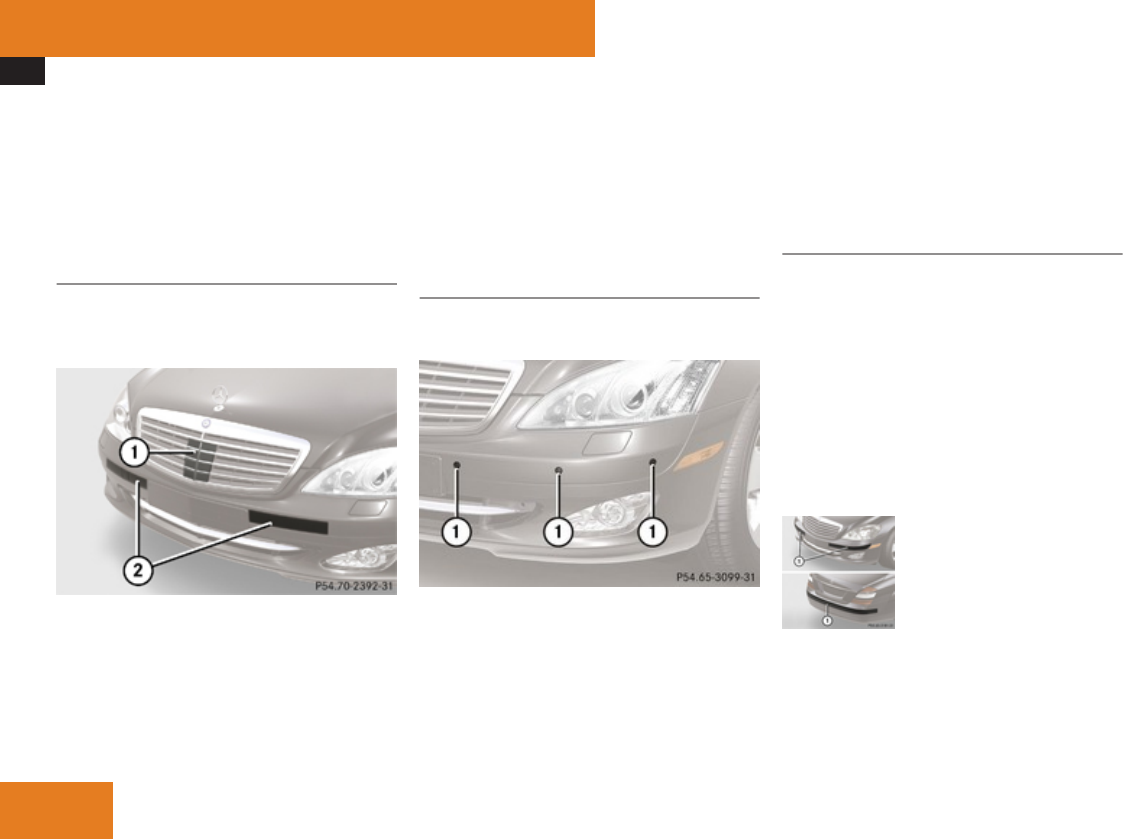
Vehicle care
486
Window cleaning solutions which are not
suitable may damage the plastic lamp
lenses of the headlamps. Therefore, do not
use abrasives, solvents or cleaners that
contain solvents.
Cleaning the DISTRONIC Plus/PRE-
SAFE® Brake system sensors
The sensors are integrated in the front
bumpers and cannot be seen from the
outside.
1Sensor cover
2Bumper area near sensors
XSwitch off the ignition.
XOnly clean sensor cover 1 by hand.
XUse a mild vehicle wash detergent, such as
Mercedes-Benz approved Car Shampoo,
with plenty of water and a non-scratching
cloth to clean sensor cover 1.
XClean a wide area of the bumpers
surrounding the sensors 2.
XRestart the engine after cleaning sensor
cover 1 and sensors 2.
Cleaning the Parktronic system sensors
Parktronic system sensors are located in the
front and rear bumper.
1Parktronic system sensors in front
bumper (Only visible without DISTRONIC
Plus)
XOnly clean sensors 1 by hand.
XUse a mild vehicle wash detergent, such as
Mercedes-Benz approved Car Shampoo,
with plenty of water and a soft, non-
scratching cloth to clean sensors 1 on the
bumpers.
! Applying strong pressure may damage
the sensor covers.
Cleaning the driving systems sensors
The sensors are integrated in the front and
rear bumpers and cannot be seen from the
outside. They work with the following
systems:
RBAS Plus
RPRE-SAFE® Brake
RBlind Spot Assist
RPark Assist
RAdvanced Parking Guidance
1Bumper area near sensors
XSwitch off the ignition.
XUse a mild car wash detergent, such as
Mercedes-Benz approved Car Shampoo,
with plenty of water and a soft, non-
Operation
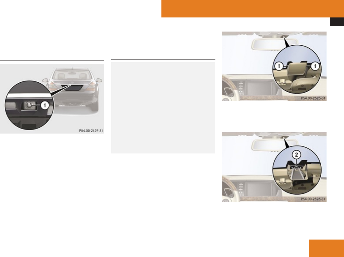
Vehicle care
487
scratching cloth to clean the bumper area
near sensors.
Cleaning the rear view camera lens
1Camera lens
XOnly use clean water and a soft, non-
scratching cloth to clean camera lens 1.
Be careful not to apply wax to camera lens
1 when waxing the vehicle. If necessary,
remove the wax using the Mercedes-Benz
approved Car Shampoo with plenty of water.
! Do not clean the camera and the area
around the camera
Rwith a high-pressure cleaner
Rwith a dry cloth and strong pressure
Rwith aggressive cleaning agents
You could otherwise damage the camera.
Cleaning the windshield in front of the
Night View Assist camera
GWarning!
Please do not forget that your primary
responsibility is to drive the vehicle. A
driver’s attention to the road must always
be his/her primary focus when driving. For
your safety and the safety of others, stop
before trying to remove window fogging or
cleaning the window in front of the Night
View Assist camera.
Bear in mind that at a speed of just 30 mph
(approximately 50 km/h), your vehicle is
covering a distance of 44 feet
(approximately 14 m) every second.
! Do not clean the lens of the Night View
Assist camera. If the camera lens is dirty,
please contact an authorized Mercedes-
Benz Center.
1Recessed handles of camera cover
XUse recessed handles 1 to swing camera
cover downward.
2Camera
XClean inside of windshield in front of
camera 2 with a soft, non-scratching
cloth.
Operation
Z

Vehicle care
488
! If you use a windshield cleaning product,
make sure that none of the cleaning
product comes into contact with the lens
of the Night View Assist camera.
XUse recessed handles 1 to swing camera
cover up.
Cleaning the windows and the wiper
blades
! The windshield wipers must be in a
vertical position before folding them away
from the windshield. They could otherwise
damage the hood.
Never open the hood when the wiper arms
are folded forward.
XMake sure the hood is fully closed.
XSwitch on the ignition.
XTurn combination switch to wiper setting
u (Y page 332).
XWith wiper arms in vertical position, switch
off the ignition.
GWarning!
For safety reasons, switch off wipers and
remove SmartKey from starter switch
(vehicles with KEYLESS-GO: Make sure the
vehicle’s on-board electronics have status
0) before cleaning the windshield and/or
the wiper blades. Otherwise, the wiper
motor could suddenly turn on and cause
injury.
! Do not pull on the wiper blade inserts.
They could tear.
XFold the wiper arms forward until they snap
into place.
XClean the windshield and the wiper blade
inserts with a clean cloth and mild
detergent solution.
XUse a soft, clean cloth and a mild window
cleaning solution on all outside and inside
glass surfaces.
An automotive glass cleaner is
recommended.
! Fold the windshield wiper arms back onto
the windshield before turning the SmartKey
in the starter switch or pressing the
KEYLESS-GO start/stop button (vehicles
with KEYLESS-GO).
Hold on to the wiper when folding the wiper
arm back. If released, the force of the
impact from the tensioning spring could
crack the windshield.
! To clean the window interior, do not use
a dry cloth, abrasives, solvents or cleaners
containing solvents. Do not touch the
inside of the front, rear or side windows
with hard objects such as an ice scraper or
ring. Doing so may damage the windows.
Cleaning the panorama roof with power
tilt/sliding panel
The rear part of the tilt/sliding panel has a
protective layer on the inside.
XUse a soft, clean cloth and a mild window
cleaning solution.
An automotive glass cleaner is
recommended.
! Do not use a dry cloth, abrasives, solvents
or cleaners containing solvents. Do not
touch the protective layer with hard objects
such as an ice scraper or ring. Never apply
strong force and only use a soft, non-
scratching cloth when cleaning the rear
part of the tilt/sliding panel.
Otherwise you may scratch or damage the
protective layer.
Operation

Vehicle care
489
Light alloy wheels
If possible, clean wheels once a week.
XUse Mercedes-Benz approved Wheel Care,
a soft bristle brush and a strong spray of
water for cleaning the light alloy wheels.
! Only use acid-free cleaning materials.
Acid may cause corrosion or damage the
clear coat.
! The vehicle should not be parked for an
extended period of time immediately after
it has been cleaned, especially not after the
wheel rims have been cleaned with wheel
rim cleaner. Wheel rim cleaners can lead to
increased corrosion of the brake disks and
brake pads. Non-approved wheel cleaners
may also damage the wheel paint if the
vehicle is not driven after cleaning.
Therefore, the vehicle’s brake system
should always be warmed-up before it is
parked after cleaning. Drive your vehicle for
several minutes to allow the brakes to dry.
When applying Mercedes-Benz approved
Tire Care and Mercedes-Benz approved
Wheel Care products, take care not to
spray them on the brake disks.
Plastic and rubber parts
XUse a gentle dishwashing detergent or mild
detergent for delicate fabrics as a washing
solution.
XWipe with a cloth moistened in a lukewarm
solution.
The surface may temporarily change color.
If this is the case, wait for it to dry.
GWarning!
Do not use cleaners or cockpit care sprays
containing solvents to clean the cockpit or
the steering wheel. Cleaners containing
solvents will make the surface porous and
vehicle occupants could suffer serious
injuries from plastic parts coming loose in
the event of air bag deployment.
! Do not use oil, wax or scouring agents.
Otherwise you may scratch or damage the
surface.
Hard plastic trim items
XUse Mercedes-Benz approved Interior Care
on a soft, lint-free cloth and apply with light
pressure.
COMAND display
! You must switch off the COMAND display
and allow it to cool prior to cleaning.
! Do not use any liquids or cleaning agents.
These can damage or even destroy the
audio display screen.
XUse a standard microfiber cloth and apply
with light pressure.
Steering wheel
XWipe with a damp cloth and dry thoroughly
or clean with Mercedes-Benz approved
Leather Care.
Carpets
XUse Mercedes-Benz approved Carpet and
Fabric Care for cleaning the carpets.
Headliner and shelf below rear window
XUse a soft bristle brush or a dry-shampoo
cleaner in case of excessive dirt.
Operation
Z

Vehicle care
490
Seat belts
XOnly use clear, lukewarm water and soap.
! The seat belts must not be treated with
chemical cleaning agents. Do not dry the
seat belts at temperatures above 176‡
(80†) or in direct sunlight.
GWarning!
Do not bleach or dye seat belts as this may
severely weaken them. In a crash they may
not be able to provide adequate protection.
Upholstery
Using aftermarket seat covers or wearing
clothing that have the tendency to give off
coloring (e.g. when wet, etc.) may cause the
upholstery to become permanently
discolored. By lining the seats with a proper
intermediate cover, contact-discoloration will
be prevented.
GWarning!
Only use seat or head restraint covers
which have been tested and approved by
Mercedes-Benz for your vehicle model.
Using other seat or head restraint covers
may interfere with or prevent
Rdeployment of the front side impact air
bags
Rdeployment of the rear side impact air
bags
Ractivation of the active head restraints
Contact an authorized Mercedes-Benz
Center for availability.
Leather upholstery
Please note that leather upholstery is a
natural product and is therefore subject to a
natural aging process. Leather upholstery
may also react to certain ambient influences
such as high humidity or high temperature by
showing wrinkles for example.
XWipe leather upholstery with a damp cloth
and dry thoroughly or clean with Mercedes-
Benz approved Leather Care.
! To avoid damage to leather upholstery:
RWipe with light pressure only.
RDo not clean with abrasive cleaning
agents such as scouring milk or powder.
RDo not soak the leather upholstery.
As leather is a natural product, it could
otherwise harden or become porous.
RExercise particular care when cleaning
perforated leather as its underside
should not become wet.
Wood trims
XOnly use water and a damp cloth to clean
wood trims in your vehicle.
! Do not use solvents like tar remover or
wheel cleaner nor polishes or waxes as
these may be abrasive.
Chrome-plated exhaust tip
Regular cleaning and care of chrome-plated
exhaust tips will help to maintain their shine
and the classy appearance.
XUse Mercedes-Benz approved Chrome
Polishing Paste each time the vehicle has
been washed, especially during the winter.
! Do not use alkaline cleaners such as
wheel cleaners as they could cause
corrosion.
Operation

491
Vehicle equipment ............................ 492
Where will I find ...? .......................... 492
Vehicle status messages in the
multifunction display ....................... 495
What to do if … .................................. 548
Unlocking/locking manually ........... 561
Resetting activated head restraints 562
Replacing SmartKey batteries ......... 564
Replacing bulbs ................................. 565
Replacing wiper blades .................... 570
Flat tire .............................................. 571
Battery ............................................... 576
Jump starting .................................... 578
Towing the vehicle ............................ 580
Fuses .................................................. 583
Practical hints
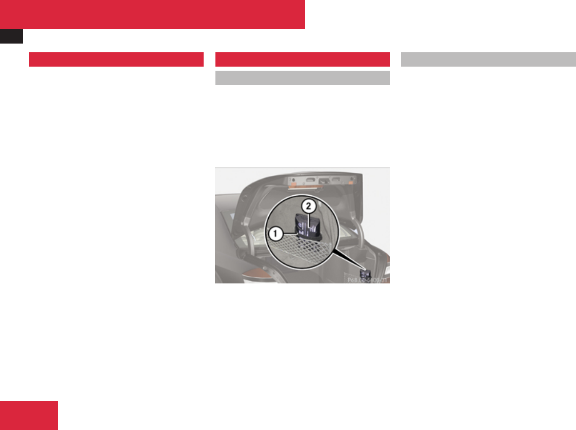
Where will I find ...?
492
Vehicle equipment
iThis Operator’s Manual describes all
features, standard or optional, potentially
available for your vehicle at the time of
purchase. Please be aware that your
vehicle might not be equipped with all
features described in this manual.
Where will I find ...?
First aid kit
iCheck expiration dates and contents for
completeness at least once a year and
replace missing/expired items.
The first aid kit is located in the trunk on the
right side storage pocket, secured by a
tensioning strap.
1Tensioning strap
2First aid kit
XLoosen tensioning strap 1.
First aid kit 2 can be removed.
Vehicle tool kit
The vehicle tool kit is located in the space
underneath the trunk floor.
The vehicle tool kit includes:
RAlignment bolt
RCollapsible wheel chock
RFuse chart
RJack
RPair of gloves
RTowing eye bolt
RWheel wrench
XRemoving: Open the trunk (Y page 302).
XLift the trunk floor using the floor handle.
XEngage the floor handle on the upper trunk
lip.
! To prevent damage, always disengage the
floor handle from the upper trunk lip and
lower the trunk floor before closing the
trunk.
Practical hints
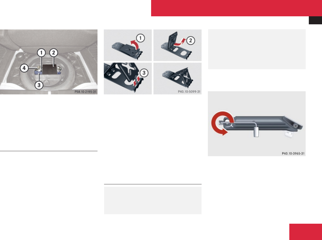
Where will I find ...?
493
1Collapsible wheel chock
2Vehicle tool kit box cover
3Tool bag
4Jack
XOpen vehicle tool kit box cover 2.
Collapsible wheel chock
The collapsible wheel chock serves to secure
the vehicle, e.g. while changing a wheel.
XTake the collapsible wheel chock from the
vehicle tool kit (Y page 492).
1Tilt the plates upward
2Fold the lower plate outward
3Insert the plate
XSetting up: Tilt both plates upward 1.
XFold the lower plate outward 2.
XGuide the tabs of the lower plate all the way
into the openings of base plate 3.
For information on where to place wheel
chocks when changing a wheel, see “Lifting
the vehicle” (Y page 572).
Jack
GWarning!
Only use the jack supplied with your vehicle
to lift the vehicle briefly for wheel changes.
If you use the jack for any other purpose,
you or others could be injured, as the jack
is designed only for the purpose of
changing a wheel.
When using the jack, observe the safety
notes in the “Mounting the spare wheel”
section and the notes on the jack.
XTake the jack from the vehicle tool kit
(Y page 492).
Storage position
XTurn the crank handle in the direction of
arrow as far as it will go.
Practical hints
Z
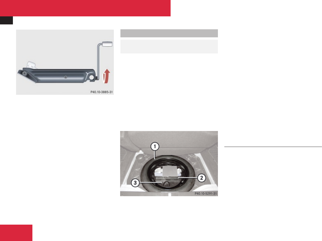
Where will I find ...?
494
Operational position
XTurn the crank handle clockwise.
Before placing the jack back into the vehicle
tool kit:
XFully collapse the jack.
XFold in the crank handle (storage position).
Spare wheel
GObserve Safety notes, see
page 571.
The spare wheel is located in the space
underneath the trunk floor.
XRemoving: Open the trunk (Y page 302).
XLift the trunk floor using the floor handle.
XEngage the floor handle on the upper trunk
lip.
! To prevent damage, always disengage the
floor handle from the upper trunk lip and
lower the trunk floor before closing the
trunk.
1Spare wheel
2Vehicle tool kit box
3Spare wheel mounting
XRemove spare wheel mounting 3 by
turning it counterclockwise.
iVehicle tool kit box 2 can only be
removed together with spare wheel
mounting 3.
After removing spare wheel mounting 3,
you can disengage vehicle tool kit box 2
from spare wheel mounting 3.
XRemove spare wheel 1.
The spare wheel bolts are located in a
container on the spare wheel rim.
XTake off the spare wheel bolts.
For information on mounting the spare wheel,
see “Flat tire” (Y page 571).
Storing the spare wheel after use
XPlace spare wheel 1 into the spare wheel
well (Y page 494).
XSecure spare wheel 1 by turning spare
wheel mounting 3 clockwise
(Y page 494).
Practical hints

Vehicle status messages in the multifunction display
495
Vehicle status messages in the
multifunction display
Notes
Warning and malfunction messages appear in
the multifunction display located in the
instrument cluster.
Certain warning and malfunction messages
are accompanied by an audible signal.
Address these messages accordingly and
follow the additional instructions given in this
Operator’s Manual.
High-priority messages are shown in red in
the multifunction display. Messages of lower
priority are also shown in yellow or white.
Certain messages of high priority cannot be
cleared from the multifunction display using
# or L on the multifunction steering
wheel (Y page 237).
Other messages of high priority and
messages of less immediate priority can be
cleared from the multifunction display using
# or L. They are then stored in the
Vehicle status message memory
(Y page 251). Remember that clearing a
message will only make the message
disappear. Clearing a message will not
correct the condition that caused the
message to appear.
GWarning!
All categories of messages contain
important information which should be
taken note of and, where a malfunction is
indicated, addressed as soon as possible at
an authorized Mercedes-Benz Center.
Failure to repair the condition noted may
cause damage not covered by the
Mercedes-Benz Limited Warranty, or result
in property damage or personal injury.
GWarning!
No messages will be displayed if either the
instrument cluster or the multifunction
display is inoperative.
As a result, you will not be able to see
information about your driving conditions,
such as speed or outside temperature,
warning/indicator lamps, malfunction/
warning messages or the failure of any
systems. Driving characteristics may be
impaired.
If you must continue to drive, please do so
with added caution. Contact an authorized
Mercedes-Benz Center as soon as possible.
On the pages that follow, you will find a
compilation of the most important warning
and malfunction messages that may appear
in the multifunction display.
For your convenience the messages are
divided into text messages (Y page 496) and
symbol messages (Y page 512).
Practical hints
Z

Vehicle status messages in the multifunction display
496
Text messages
Safety systems
Display messages Possible cause/consequence Possible solution
PRE-SAFE Inoperative
See Oper. Manual
The PRE-SAFE® system itself has failed.
All other occupant safety systems, such
as the air bags, are still available.
XContact an authorized Mercedes-Benz Center
as soon as possible.
PRE-SAFE Function Currently
Limited See Oper.
Manual
The PRE-SAFE® Brake is switched off and
is temporarily unavailable.
The PRE-SAFE® Brake is deactivated if:
Rthe DISTRONIC Plus cover in the
radiator grille is dirty
Rthe area around the sensors in the front
or the rear bumper is dirty
Rits function is impaired as a result of
heavy precipitation
Rthe radar sensor system is temporarily
inoperative due to electromagnetic
interference near television and radio
transmitter stations, toll stations,
speed measuring systems, etc.
Rthe system is out of the operating
temperature range
Rthe battery voltage is insufficient
The PRE-SAFE® Brake becomes operational
again and the message in the multifunction
display disappears when:
Rdirt on the radiator grille has fallen off while
driving (e.g. slush or snow)
Rthe system recognizes full sensor availability
(due to lessening rain or the road surface
drying)
Rthe system is within the operating temperature
range
If the message in the multifunction display does
not disappear:
XClean the DISTRONIC Plus cover in the radiator
grille (Y page 486).
XClean the front and the rear bumper
(Y page 486).
XRestart the vehicle.
XWait until the battery recovers.
Practical hints

Vehicle status messages in the multifunction display
497
Display messages Possible cause/consequence Possible solution
PRE-SAFE Function Limited
See Oper. Manual
The PRE-SAFE® Brake is unavailable due
to a malfunction.
The BAS Plus may also be unavailable.
XContact an authorized Mercedes-Benz Center
as soon as possible.
Practical hints
Z

Vehicle status messages in the multifunction display
498
Display messages Possible cause/consequence Possible solution
Front Passenger Airbag Enabled
See Oper. Manual
The front passenger front air bag is
activated while driving even though a
child, small individual, or object below the
system’s weight threshold is on the front
passenger seat, or the front passenger
seat is empty. Objects on the seat or
forces acting on the seat may make the
system sense supplemental weight.
XStop the vehicle in a safe location as soon as
possible.
XEngage the electronic parking brake.
XSwitch off the ignition.
XOpen the front passenger door.
XRemove child and child restraint from front
passenger seat and properly secure the child
in rear seat employing the child restraint if
necessary.
XRemove any other items from on and around
the front passenger seat and make sure the
storage bag on the back of the front passenger
seat is empty.
XMake sure no objects which apply forces to the
seat are present (e.g. objects such as books,
briefcases etc. lodged behind or around the
seat, head restraints pushing against roof etc.).
The system may recognize such forces as
supplemental weight and sense that an
occupant on the front passenger seat is of a
greater weight than actually present.
XKeep the seat unoccupied, close the front
passenger door and switch on the ignition.
Monitor the 59 indicator lamp right
of the instrument cluster (Y page 53) and the
Practical hints

Vehicle status messages in the multifunction display
499
Display messages Possible cause/consequence Possible solution
multifunction display in the instrument cluster
(Y page 30) for the following:
With the seat unoccupied and the ignition
switched on,
Rthe 59 indicator lamp right of the
instrument cluster should illuminate and
remain illuminated, indicating that the OCS
(Y page 50) has deactivated the front
passenger front air bag.
Rthe message Front Passenger Airbag
Enabled See Oper. Manual or the message
Front Passenger Airbag Disabled See
Oper. Manual should not appear in the
multifunction display at any time the seat is
unoccupied. Wait at least 60 seconds for the
system to complete the necessary check
cycles and to make sure neither message
appears in the multifunction display.
If above conditions are met, you can occupy the
front passenger seat again. Depending on the
front passenger classification sensed by the
OCS, the 59 indicator lamp will
remain illuminated or go out.
If above conditions are not met, the system is not
working properly. Have the system checked as
Practical hints
Z

Vehicle status messages in the multifunction display
500
Display messages Possible cause/consequence Possible solution
soon as possible at an authorized Mercedes-Benz
Center.
GWarning!
If the 59 indicator lamp
remains out even after performing the
above corrective steps, do not have any
children 12 years old and under and other
small individuals use the front passenger
seat until the system has been repaired.
Practical hints

Vehicle status messages in the multifunction display
501
Display messages Possible cause/consequence Possible solution
Front Passenger Airbag Disabled
See Oper. Manual
The front passenger front air bag is
deactivated while driving even though an
adult or someone larger than a small
individual is occupying the front
passenger seat. Forces acting on the seat
may make the system sense a decrease
in weight.
XStop the vehicle in a safe location as soon as
possible.
XEngage the electronic parking brake.
XSwitch off the ignition.
XHave the front passenger vacate the seat and
exit the vehicle.
XAdjust the seat height to a higher position
(Y page 310).
XMake sure no objects which apply forces to the
seat are present (e.g. objects such as books,
briefcases etc. lodged underneath, behind or
around the seat). Such forces may cause the
system to sense that an occupant of a lesser
weight than actually present is on the front
passenger seat.
XKeep the seat unoccupied, close the front
passenger door and switch on the ignition.
Monitor the 59 indicator lamp right
of the instrument cluster (Y page 53) and the
multifunction display in the instrument
(Y page 30) cluster for the following:
With the seat unoccupied and the ignition
switched on,
Rthe 59 indicator lamp right of the
instrument cluster should illuminate and
remain illuminated, indicating that the OCS
Practical hints
Z

Vehicle status messages in the multifunction display
502
Display messages Possible cause/consequence Possible solution
(Y page 50) has deactivated the front
passenger front air bag.
Rthe message Front Passenger Airbag
Enabled See Oper. Manual or the message
Front Passenger Airbag Disabled See
Oper. Manual should not appear in the
multifunction display at any time the seat is
unoccupied. Wait at least 60 seconds for the
system to complete the necessary check
cycles and to make sure neither message
appears in the multifunction display.
If above conditions are met, you can occupy the
front passenger seat again. Depending on the
front passenger classification sensed by the
OCS, the 59 indicator lamp will
remain illuminated or go out.
If above conditions are not met, the system is not
working properly. Have the system checked as
soon as possible at an authorized Mercedes-Benz
Center.
GWarning!
If the 59 indicator lamp
remains illuminated with an adult occupant
on the front passenger seat even after
performing the above corrective steps, do
not have any passenger use the front
passenger seat until the system has been
repaired.
Practical hints

Vehicle status messages in the multifunction display
503
Driving systems
Display messages Possible cause/consequence Possible solution
Cruise Control - - - mph One of the activation conditions for the
cruise control has not been fulfilled. For
example, you have attempted to set a
speed below 20 mph (30 km/h).
XDrive faster than 20 mph (30 km/h), if the
situation allows, and set the speed.
XCheck the activation conditions for the cruise
control (Y page 357).
Cruise Control Inoperative The cruise control is malfunctioning. XHave the cruise control checked at an
authorized Mercedes-Benz Center.
Practical hints
Z

Vehicle status messages in the multifunction display
504
Display messages Possible cause/consequence Possible solution
DISTRONIC PLUS Currently
Unavailable
See Oper. Manual
The DISTRONIC Plus is switched off and is
temporarily unavailable.
The DISTRONIC Plus is deactivated if:
Rthe DISTRONIC Plus cover in the
radiator grille is dirty
Rits function is impaired as a result of
heavy precipitation
Rthe radar sensor system is temporarily
inoperative due to electromagnetic
interference near television and radio
transmitter stations, toll stations,
speed measuring systems, etc.
Rthe radar sensors do not sense any
other vehicles or objects, i.e. road sign
or similar to this, for a long time
Rthe system is out of the operating
temperature range
Rthe battery voltage is insufficient
XIf necessary, clean the DISTRONIC Plus cover
in the radiator grille (Y page 486).
XRestart the vehicle.
XTry activating the DISTRONIC Plus again later.
XWait until the system is within the operating
temperature range or the battery recovers.
The DISTRONIC Plus becomes operational again
without the engine being restarted when:
Rdirt on the radiator grille has fallen off while
driving (e.g. slush or snow)
Rthe system recognizes full sensor availability
(due to lessening rain or the road surface
drying)
Rthe message in the multifunction display
disappears
DISTRONIC PLUS Inoperative The DISTRONIC Plus is malfunctioning.
The BAS Plus and the PRE-SAFE® Brake
are also not available.
XContact an authorized Mercedes-Benz Center
as soon as possible.
DISTRONIC PLUS Override You have accelerated. The DISTRONIC
Plus has switched off.
XStop accelerating.
Practical hints

Vehicle status messages in the multifunction display
505
Display messages Possible cause/consequence Possible solution
DISTRONIC PLUS - - - mph One of the activation conditions for the
DISTRONIC Plus has not been fulfilled. For
example, you have attempted to set a
speed below 20 mph (30 km/h).
XDrive faster than 20 mph (30 km/h), if the
situation allows, and set the speed.
XCheck the activation conditions for the
DISTRONIC Plus (Y page 365).
Park Assist Currently
Unavailable
See Oper. Manual
The Park Assist is deactivated because
the area around the sensors in the front
or the rear bumper is dirty.
XClean the front and rear bumper
(Y page 486).
The Park Assist is deactivated because
the battery voltage is insufficient.
XHave the battery checked at an authorized
Mercedes-Benz Center.
The Park Assist is switched off because
the radar sensor system is temporarily
inoperative due to electromagnetic
interference near television and radio
transmitter stations, toll stations, speed
measuring systems, etc.
XWait until the message in the multifunction
display disappears.
Park Assist Inoperative The Park Assist is unavailable due to a
malfunction.
XContact an authorized Mercedes-Benz Center
as soon as possible.
Practical hints
Z

Vehicle status messages in the multifunction display
506
Display messages Possible cause/consequence Possible solution
Blind Spot
Assist
Currently
Unavailable
See Oper. Manual
The Blind Spot Assist is deactivated
because the area around the sensors in
the front or the rear bumper is dirty.
XClean the front and rear bumper
(Y page 486).
The Blind Spot Assist is deactivated
because the battery voltage is insufficient.
XHave the battery checked at an authorized
Mercedes-Benz Center.
The Blind Spot Assist is switched off
because the radar sensor system is
temporarily inoperative due to
electromagnetic interference near
television and radio transmitter stations,
toll stations, speed measuring systems,
etc.
XWait until the message in the multifunction
display disappears.
Blind Spot
Assist
Inoperative The Blind Spot Assist is unavailable due to
a malfunction.
XContact an authorized Mercedes-Benz Center
as soon as possible.
Practical hints

Vehicle status messages in the multifunction display
507
Display messages Possible cause/consequence Possible solution
Parking
Guidance
Currently
Unavailable
See Oper. Manual
The Advanced Parking Guidance is
deactivated because the area around the
sensors in the front or the rear bumper is
dirty.
XClean the front and rear bumper
(Y page 486).
The Advanced Parking Guidance is
deactivated because the battery voltage
is insufficient.
XHave the battery checked at an authorized
Mercedes-Benz Center.
The Advanced Parking Guidance is
switched off because the radar sensor
system is temporarily inoperative due to
electromagnetic interference near
television and radio transmitter stations,
toll stations, speed measuring systems,
etc.
XWait to see if the interference is temporary or
do not use Advanced Parking Guidance. Try in
a location where the interfering transmission
might not be present.
Parking
Guidance
Canceled The Advanced Parking Guidance has been
canceled because:
Rthe vehicle is sliding
Rthe bumper became dirty in the area of
the sensors
Rthere has been a malfunction
XUse the Advanced Parking Guidance again
later.
If the parking space symbol is not shown in the
multifunction display at a speed below 10 mph
(16 km/h):
XClean the bumpers (Y page 486).
or
XRestart the engine.
or
XContact an authorized Mercedes-Benz Center.
Practical hints
Z

Vehicle status messages in the multifunction display
508
Display messages Possible cause/consequence Possible solution
Parking
Guidance
Finished Advanced Parking Guidance: The vehicle
is in the end position.
The display message disappears automatically.
Radar Sensors Deactivated
See Oper. Manual
You have attempted to activate the
DISTRONIC Plus, the Park Assist or the
PRE-SAFE® Brake even though you have
switched off the radar sensors on the
vehicle.
XCheck if the radar sensors may be switched on
(Y page 253).
XSwitch on the radar sensors using the
instrument cluster control system.
Vehicle
Display messages Possible cause/consequence Possible solution
Apply Brake to Shift from 'P' You have attempted to shift the automatic
transmission into drive position D, reverse
gear R or neutral position N without
depressing the brake pedal.
XDepress the brake pedal.
Door Open Vehicle Not in Park You have opened the driver’s door and the
automatic transmission is still in drive
position D, reverse gear R or neutral
position N.
XBefore you leave the vehicle, make sure the
automatic transmission is in park position P
and the electronic parking brake is engaged.
Only Shift to
Position 'P'
When Vehicle Is
Stationary
You have attempted to shift the automatic
transmission into park position P although
the vehicle was still in motion.
XStop your vehicle as soon as it is safe to do so.
XShift the automatic transmission to park
position P.
XEngage the electronic parking brake.
Practical hints

Vehicle status messages in the multifunction display
509
Display messages Possible cause/consequence Possible solution
Shift to P or N to Start Engine You have attempted to start the engine
while the automatic transmission was in
reverse gear R or drive position D.
XShift the automatic transmission into park
position P or neutral position N.
Auxiliary
Battery
Malfunction The backup battery for the automatic
transmission is no longer charging.
XContact an authorized Mercedes-Benz Center.
Auxiliary
Battery
Malfunction The backup battery for the automatic
transmission is discharged. In case of
failure of the on-board electrical system,
you may not be able change transmission
positions.
XStop the vehicle in a safe location or as soon
as it is safe to do so.
XEngage the electronic parking brake.
XDo not drive any further.
XContact an authorized Mercedes-Benz Center
or call Roadside Assistance.
Service
Required
Do Not Shift Gears The automatic transmission cannot be
shifted out of the set position because of
a malfunction.
If the automatic transmission is in drive position
D:
XWithout shifting the automatic transmission
out of drive position D, drive to an authorized
Mercedes-Benz Center.
If the automatic transmission is set to position
neutral position N, reverse gear R or park position
P:
XDo not drive.
XContact an authorized Mercedes-Benz Center.
Next Service X in ... days
in ... mls (km)
The specified maintenance service must
be carried out within the remaining time
range or driving distance (Y page 481).
XHave the maintenance service carried out at an
authorized Mercedes-Benz Center.
Practical hints
Z

Vehicle status messages in the multifunction display
510
Display messages Possible cause/consequence Possible solution
Service X Due The specified maintenance service must
be carried out (Y page 481).
XHave the maintenance service carried out at an
authorized Mercedes-Benz Center as soon as
possible.
Service X
Exceeded
by X days
by XXX mls (km)
The specified maintenance service term
has been exceeded (Y page 482).
XHave the maintenance service carried out at an
authorized Mercedes-Benz Center as soon as
possible.
! Failure to have the vehicle maintained in
accordance with the Maintenance Booklet
and maintenance service indicator at the
designated times/mileage will result in
vehicle damage not covered by the
Mercedes-Benz Limited Warranty.
Tires
Display messages Possible cause/consequence Possible solution
Tire Pressures Displayed After
Driving
A Few Minutes
The tire inflation pressure is being
checked.
XDrive the vehicle for a few minutes.
Tire Pressure
Monitor
Inoperative The Advanced TPMS or a wheel sensor is
malfunctioning.
XHave the Advanced TPMS checked at an
authorized Mercedes-Benz Center.
Tire Pressure
Monitor
Inoperative
No Wheel Sensors
The Advanced TPMS is deactivated
because wheels without proper sensors
were installed.
XHave the appropriate wheel sensors installed
at an authorized Mercedes-Benz Center.
As soon as all wheels with sensors have been
mounted, the Advanced TPMS is switched back
on after driving for several minutes.
Practical hints

Vehicle status messages in the multifunction display
511
Display messages Possible cause/consequence Possible solution
Tire Pressure
Monitor
Currently
Unavailable
The Advanced TPMS is unable to monitor
the tire inflation pressure due to:
Ra nearby radio interference source
Rthe on-board voltage is too low
Rexcessive wheel sensor temperatures
As soon as the causes of the malfunction have
been removed, the Advanced TPMS becomes
active again automatically after a few minutes
driving.
GWarning!
Do not drive with a flat tire. A flat tire affects the ability to steer or brake the vehicle. You may lose control of the vehicle. Continued driving
with a flat tire will cause excessive heat build-up and possibly a fire.
GWarning!
Follow recommended tire inflation pressures.
Do not underinflate tires. Underinflated tires wear excessively and/or unevenly, adversely affect handling and fuel economy, and are more
likely to fail from being overheated.
Do not overinflate tires. Overinflated tires can adversely affect handling and ride comfort, wear unevenly, increase stopping distance, and
result in sudden deflation (blowout) because they are more likely to become punctured or damaged by road debris, potholes etc.
Practical hints
Z

Vehicle status messages in the multifunction display
512
Symbol messages
Brake
Display messages Possible cause/consequence Possible solution
(USA only)
(Canada only)
Check Brake Fluid
Level
There is insufficient brake fluid in the
reservoir.
Risk of accident!
XStop the vehicle in a safe location or as soon
as it is safe to do so.
XEngage the electronic parking brake.
XDo not drive any further.
XContact an authorized Mercedes-Benz Center
or call Roadside Assistance.
Do not add brake fluid! This will not solve the
problem.
GWarning!
Driving with the message Check Brake Fluid Level displayed can result in an accident. Have your brake system checked immediately.
Do not add brake fluid before checking the brake system. Overfilling the brake fluid reservoir can result in spilling brake fluid on hot engine
parts and the brake fluid catching fire. You can be seriously burned.
! If you find that the brake fluid in the brake fluid reservoir has fallen to the minimum mark or below, have the brake system checked for
brake pad thickness and leaks.
Practical hints

Vehicle status messages in the multifunction display
513
Display messages Possible cause/consequence Possible solution
(USA only)
(Canada only)
Brake Immediately A malfunction has occurred while
DISTRONIC Plus was switched on.
XWhile observing surrounding traffic conditions
and when it is safe, immediately depress the
brake pedal firmly until the warning message
disappears.
XSecure vehicle from rolling away before getting
out of it (Y page 343).
(USA only)
(Canada only)
EBR, ABS, and ESP
Inoperative
See Oper. Manual
The brake system is still functioning
normally but due to a malfunction, the
ABS, the BAS, the BAS Plus, the EBP, the
ESP®, the PRE-SAFE® and the PRE-
SAFE® Brake are unavailable.
XContinue driving with added caution. Wheels
may lock during hard braking, reducing
steering capability.
XAdjust driving to be consistent with reduced
braking responsiveness.
XHave the system checked at an authorized
Mercedes-Benz Center as soon as possible.
Failure to follow these instructions increases the
risk of an accident.
Practical hints
Z

Vehicle status messages in the multifunction display
514
Display messages Possible cause/consequence Possible solution
(USA only)
(Canada only)
Service
See Oper. Manual
S 600 and S 65 AMG only:
The brake system sensors are
malfunctioning. The brake system
continues to function normally with full
brake force boost.
XContinue driving with added caution.
XHave the system checked at an authorized
Mercedes-Benz Center as soon as possible.
Practical hints

Vehicle status messages in the multifunction display
515
Display messages Possible cause/consequence Possible solution
(USA only)
(Canada only)
Parking Brake
See Oper. Manual
In addition, the red indicator lamp for the
electronic parking brake is either on or off
and the yellow warning lamp for the
electronic parking brake comes on.
The electronic parking brake is
malfunctioning.
To release:
XPull handle of electronic parking brake.
or
XDrive off carefully.
XContact an authorized Mercedes-Benz Center
as soon as possible.
To engage:
XSwitch off ignition and press handle for
electronic parking brake for at least
10 seconds, until the warning message in the
multifunction display disappears.
If the warning message does not disappear:
XShift the automatic transmission to park
position P (Y page 346).
XProtect vehicle from rolling away while parked
by using a chock from the vehicle tool kit
(Y page 493).
XContact an authorized Mercedes-Benz Center
as soon as possible.
Practical hints
Z

Vehicle status messages in the multifunction display
516
Display messages Possible cause/consequence Possible solution
(USA only)
(Canada only)
Parking Brake
See Oper. Manual
In addition, the red indicator lamp for the
electronic parking brake flashes.
The power supply for the electronic
parking brake was malfunctioning or the
electronic parking brake was previously
mechanically released.
XPull handle of electronic parking brake.
or
XDrive off carefully.
or
XPress handle for electronic parking brake until
the warning message in the multifunction
display disappears.
(USA only)
(Canada only)
Parking Brake
See Oper. Manual
In addition, the red indicator lamp for the
electronic parking brake flashes and the
yellow warning lamp for the electronic
parking brake comes on.
The electronic parking brake is
malfunctioning.
XSwitch ignition off and back on again, and
engage or release electronic parking brake.
or
XDrive off carefully.
XContact an authorized Mercedes-Benz Center
as soon as possible.
Practical hints

Vehicle status messages in the multifunction display
517
Display messages Possible cause/consequence Possible solution
(USA only)
(Canada only)
Parking Brake
See Oper. Manual
When you engage or release the
electronic parking brake, the red indicator
lamp for the electronic parking brake
flashes for approx. 10 seconds.
Afterward, it goes out or comes on
continuously. The yellow warning lamp for
the electronic parking brake comes on.
The electronic parking brake is
malfunctioning or overheated for example
due to overvoltage or undervoltage.
XDrive off carefully.
XContact an authorized Mercedes-Benz Center
as soon as possible.
In the event of overvoltage or undervoltage:
XRemove the cause of the overvoltage or
undervoltage, e.g. charge the battery or restart
the engine.
XSwitch ignition off and back on again, and
engage or release electronic parking brake.
If the electronic parking brake still cannot be
released:
XContact an authorized Mercedes-Benz Center
as soon as possible.
If overheated:
XLet vehicle cool down, and do not engage
electronic parking brake during this time.
or
XSwitch ignition off and back on again, and
engage or release electronic parking brake.
Practical hints
Z

Vehicle status messages in the multifunction display
518
Display messages Possible cause/consequence Possible solution
(USA only)
(Canada only)
Parking Brake
Inoperative
When you engage or release the
electronic parking brake, the red indicator
lamp for the electronic parking brake
flashes and goes out after approx.
10 seconds. The yellow warning lamp for
the electronic parking brake comes on.
The electronic parking brake is
malfunctioning.
XSwitch ignition off and back on again, and
engage or release electronic parking brake.
If the electronic parking brake cannot be
engaged:
XShift the automatic transmission to park
position P (Y page 346).
XProtect vehicle from rolling away while parked
by using a chock from the vehicle tool kit
(Y page 493).
XContact an authorized Mercedes-Benz Center
as soon as possible.
(USA only)
(Canada only)
Please Release
Parking Brake
In addition, the red indicator lamp for the
electronic parking brake flashes and an
acoustic warning sounds.
You are driving with the electronic parking
brake engaged, or you are carrying out an
emergency brake application with the
electronic parking brake (Y page 343).
XRelease electronic parking brake.
or
XDrive off carefully.
or
XRelease the handle for electronic parking
brake.
Practical hints

Vehicle status messages in the multifunction display
519
Display messages Possible cause/consequence Possible solution
(USA only)
(Canada only)
Please Release
Parking Brake
In addition, the red indicator lamp for the
electronic parking brake flashes, the
yellow warning lamp for the electronic
parking brake comes on and an acoustic
warning sounds.
The electronic parking brake is
malfunctioning; braking action is
restricted.
While driving:
XRelease the handle for electronic parking
brake.
While at a standstill:
XSwitch off ignition and press handle for
electronic parking brake until the warning
message disappears from the multifunction
display.
If the warning message does not disappear:
XShift the automatic transmission to park
position P (Y page 346).
XProtect vehicle from rolling away while parked
by using a chock from the vehicle tool kit
(Y page 493).
XContact an authorized Mercedes-Benz Center
as soon as possible.
Practical hints
Z

Vehicle status messages in the multifunction display
520
Display messages Possible cause/consequence Possible solution
(USA only)
(Canada only)
Turn On the
Ignition to
Release the
Parking Brake
In addition, the red indicator lamp for the
electronic parking brake comes on.
You have tried to release the electronic
parking brake, but the ignition was not
switched on.
XSwitch on the ignition.
Check
Brake Pad Wear
The brake pads have reached their wear
limit.
XHave the brake pads replaced as soon as
possible.
! Brake pad thickness must be visually
inspected by a qualified technician at the
intervals specified in the Maintenance
Booklet.
Practical hints

Vehicle status messages in the multifunction display
521
Safety systems
Display messages Possible cause/consequence Possible solution
ABS and ESP
Inoperative
See Oper. Manual
The brake system is still functioning
normally but due to a malfunction, the
ABS, the BAS, the BAS Plus, the ESP®, the
PRE-SAFE® system and the PRE-SAFE®
Brake are unavailable.
XContinue driving with added caution. Wheels
may lock during hard braking, reducing
steering capability.
XHave the system checked at an authorized
Mercedes-Benz Center as soon as possible.
Failure to follow these instructions increases the
risk of an accident.
ABS and ESP
Currently
Unavailable
See Oper. Manual
The brake system is still functioning
normally but due to a malfunction, the
ABS, the BAS, the BAS Plus, the ESP®, the
PRE-SAFE® system and the PRE-SAFE®
Brake are unavailable.
The self-diagnosis may not be completed
yet.
XDrive a short distance with added caution at a
vehicle speed of above 12 mph (20 km/h).
When the message disappears, the ABS and
the ESP® are available again.
ABS and ESP
Currently
Unavailable
See Oper. Manual
The brake system still functions normally
but due to insufficient power supply, the
ABS, the BAS, the BAS Plus, the ESP®, the
PRE-SAFE® system and the PRE-SAFE®
Brake are not available.
When the voltage is above the required value
again, the ABS, the BAS, the BAS Plus, the
ESP® and the PRE-SAFE® system are operational
again and the message should disappear.
If the message does not disappear:
XHave the alternator and the battery checked.
Practical hints
Z

Vehicle status messages in the multifunction display
522
Display messages Possible cause/consequence Possible solution
Inoperative
See Oper. Manual
ESP® as well as the PRE-SAFE® system
are switched off due to a malfunction.
In addition, the yellow ESP® warning lamp
v comes on.
The ABS may not be operational and the
following systems are not available:
RBAS and BAS Plus
RPRE-SAFE® Brake
RDISTRONIC Plus
RCruise control
RHill start assist system
XContinue driving with added caution.
XHave the system checked at an authorized
Mercedes-Benz Center as soon as possible.
Failure to follow these instructions increases the
risk of an accident.
Practical hints

Vehicle status messages in the multifunction display
523
Display messages Possible cause/consequence Possible solution
Inoperative
See Oper. Manual
S 600 and S 65 AMG only:
The ESP® as well as the PRE-SAFE®
system are switched off due to a
malfunction.
In addition, the v and ; (USA only)
or 3 (Canada only) warning lamps in
the instrument cluster come on.
Brake force assistance is impaired and is
sustained through an electric substitute
function as long as the engine is running.
The brake system continues to function
normally. You will feel a pulsating effect at
the brake pedal while braking.
The BAS Plus and the PRE-SAFE® Brake
are also not available.
XContinue driving with added caution.
XHave the system checked at an authorized
Mercedes-Benz Center as soon as possible.
Failure to follow these instructions increases the
risk of an accident.
Currently
Unavailable
See Oper. Manual
The ESP® and the PRE-SAFE® system are
temporarily unavailable. It is possible that
the self-diagnostics have not yet
completed.
In addition, the yellow ESP® warning lamp
v comes on.
The brake system still functions normally.
The BAS Plus and the PRE-SAFE® Brake
are also not available.
Synchronize the ESP®:
XDrive a short distance with gentle turns at a
speed above 12 mph (20 km/h).
The message disappears when ESP® is again
available.
Practical hints
Z

Vehicle status messages in the multifunction display
524
Display messages Possible cause/consequence Possible solution
Currently
Unavailable
See Oper. Manual
The ESP® and the PRE-SAFE® system are
switched off due to undervoltage. It is
possible that the battery is not charged.
The brake system still functions normally.
The BAS Plus and the PRE-SAFE® Brake
are also not available.
XContinue driving with added caution.
XHave the system checked at an authorized
Mercedes-Benz Center as soon as possible.
Failure to follow these instructions increases the
risk of an accident.
Currently
Unavailable
See Oper. Manual
If the yellow ESP® warning lamp v
flashes while driving and this message
appears, the Electronic Traction System
(ETS/4-ETS) has switched off to prevent
overheating of the drive wheel brakes.
The BAS Plus and the PRE-SAFE® Brake
are also not available.
As soon as the brakes have cooled off, the
Electronic Traction System (ETS/4-ETS)
switches on again.
The message in the multifunction display
disappears and the ESP® warning lamp v
goes out.
Tele Aid
Inoperative
One or more main functions of the Tele Aid
system are malfunctioning.
XHave the Tele Aid system checked at an
authorized Mercedes-Benz Center.
SRS Malfunction
Service Required
There is a malfunction in the supplemental
restraint systems. The air bags or
Emergency Tensioning Devices (ETDs)
could deploy unexpectedly or fail to
activate in an accident.
XDrive with added caution to the nearest
authorized Mercedes-Benz Center.
Practical hints

Vehicle status messages in the multifunction display
525
Display messages Possible cause/consequence Possible solution
Front Left SRS
Malfunction
Service Required
Components of the driver’s supplemental
restraint system may not work properly.
XDrive with added caution to the nearest
authorized Mercedes-Benz Center.
Front Right SRS
Malfunction
Service Required
Components of the front passenger’s
supplemental restraint system may not
work properly.
XDrive with added caution to the nearest
authorized Mercedes-Benz Center.
Rear Left SRS
Malfunction
Service Required
Components of the left rear passenger’s
supplemental restraint system may not
work properly.
XDrive with added caution to the nearest
authorized Mercedes-Benz Center.
Rear Center SRS
Malfunction
Service Required
Components of the center rear
passenger’s supplemental restraint
system may not work properly.
XDrive with added caution to the nearest
authorized Mercedes-Benz Center.
Rear Right SRS
Malfunction
Service Required
Components of the right rear passenger’s
supplemental restraint system may not
work properly.
XDrive with added caution to the nearest
authorized Mercedes-Benz Center.
Left Side Curtain
Airbag Malfunction
Service Required
The left window curtain air bag may not
work properly.
XDrive with added caution to the nearest
authorized Mercedes-Benz Center.
Practical hints
Z

Vehicle status messages in the multifunction display
526
Display messages Possible cause/consequence Possible solution
Right Side Curtain
Airbag Malfunction
Service Required
The right window curtain air bag may not
work properly.
XDrive with added caution to the nearest
authorized Mercedes-Benz Center.
GWarning!
In the event a malfunction of the SRS is indicated as outlined above, the SRS may not be operational.
For your safety, we strongly recommend that you contact an authorized Mercedes-Benz Center immediately to have the system checked.
Otherwise the SRS may not be activated when needed in an accident, which could result in serious or fatal injury, or it might deploy
unexpectedly and unnecessarily which could also result in injury.
Practical hints

Vehicle status messages in the multifunction display
527
Driving systems
Display messages Possible cause/consequence Possible solution
Malfunction
Stop Vehicle
You have started driving although the
vehicle level is still too low.
The vehicle is being raised. The ABC
message goes out after a few seconds.
XStop your vehicle in a safe location or as soon
as it is safe to do so.
XEngage the electronic parking brake.
XWait until the message disappears from the
multifunction display.
You may then drive off.
Malfunction
Stop Vehicle
The vehicle is losing oil.
The ABC message is continuously shown.
XStop your vehicle in a safe location or as soon
as it is safe to do so.
XEngage the electronic parking brake.
XCall Roadside Assistance.
or
XContact an authorized Mercedes-Benz Center.
Malfunction
Stop Vehicle
The ABC is malfunctioning.
The ABC message is continuously shown.
XAvoid large steering maneuvers. The fenders or
tires could otherwise be damaged. Listen for
scraping noises.
XDo not drive faster than 50 mph (80 km/h).
XContact an authorized Mercedes-Benz Center
as soon as possible.
Malfunction The capability of the ABC system is
restricted. This can impair handling.
XDo not drive faster than 50 mph (80 km/h).
XContact an authorized Mercedes-Benz Center
as soon as possible.
Practical hints
Z

Vehicle status messages in the multifunction display
528
Display messages Possible cause/consequence Possible solution
Vehicle Rising
Please Wait
Briefly
The vehicle’s level is too low while at a
standstill. The vehicle will be raised.
XWait until the message disappears from the
multifunction display.
STOP,
Car Too Low
You have started driving although the
vehicle level was too low.
The vehicle will be raised.
XStop your vehicle as soon as it is safe to do so.
XEngage the electronic parking brake.
XWait until the message disappears from the
multifunction display.
You may then drive off.
STOP,
Car Too Low
The AIRMATIC is malfunctioning. XStop and press the vehicle level control switch
to select a higher vehicle level (Y page 373).
XAvoid large steering maneuvers. The fenders or
tires could otherwise be damaged. Listen for
scraping noises.
XDo not drive faster than 50 mph (80 km/h).
XContact an authorized Mercedes-Benz Center
as soon as possible.
There is otherwise danger of an accident.
Malfunction The capability of the AIRMATIC system is
restricted. This can impair the handling.
XDo not drive faster than 50 mph (80 km/h).
XContact an authorized Mercedes-Benz Center
as soon as possible.
Practical hints

Vehicle status messages in the multifunction display
529
Display messages Possible cause/consequence Possible solution
Vehicle Rising
Please Wait
Briefly
Vehicles with AIRMATIC:
The vehicle level is too low.
XWait until the message disappears from the
multifunction display.
Night View Assist
Inoperative
Night View Assist is malfunctioning. XContact an authorized Mercedes-Benz Center
as soon as possible.
Night View Assist
Currently
Unavailable
The temperature of the camera is too high
(Y page 390).
XWait until the message Night View Assist
Available Again appears.
In addition you can:
XSwing the camera cover down (Y page 487).
XAdjust the air distribution of the climate control
so that air flows upward (Y page 228).
Night View Assist
Lights Must Be Set
to AUTO or ON
You have tried to switch on Night View
Assist, but the exterior lamp switch is not
set to * or B.
XTurn the exterior lamp switch to * or
B (Y page 325).
Night View Assist
Not In Reverse Gear
You have tried to switch on Night View
Assist while the automatic transmission
was in reverse gear R.
XShift the automatic transmission to park
position P, neutral position N or drive position
D (Y page 345).
Practical hints
Z
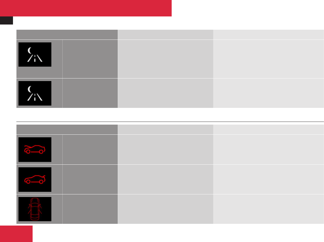
Vehicle status messages in the multifunction display
530
Display messages Possible cause/consequence Possible solution
Night View Assist
Lights ON or AUTO,
Not in R Gear
You have tried to switch on Night View
Assist, but the light switch is not set to
* or B.
In addition, the automatic transmission is
in reverse gear R.
XTurn the exterior lamp switch to * or
B (Y page 325).
XShift the automatic transmission to park
position P, neutral position N or drive position
D (Y page 345).
Night View Assist
Only When
It Is Dark
You have tried to switch on Night View
Assist by daylight.
You can only switch on Night View Assist when it
is dark.
Vehicle
Display messages Possible cause/consequence Possible solution
You are driving with the hood open. XClose the hood (Y page 444).
You are driving with the trunk open. XClose the trunk.
You are driving with at least one door
open. The display symbol shows you
which doors are open.
XClose all doors.
Practical hints

Vehicle status messages in the multifunction display
531
Display messages Possible cause/consequence Possible solution
Shift to P You have attempted to turn off the engine
with the KEYLESS-GO start/stop button
and opened the driver’s door with the
automatic transmission not shift to park
position P.
XShift the automatic transmission to park
position P (Y page 345).
or
XClose the driver’s door.
Key
Not Detected
The SmartKey with KEYLESS-GO is not
detected while the engine is running
because the SmartKey is not in the
vehicle.
XStop the vehicle as soon as it is safe to do so.
XEngage the electronic parking brake.
XSearch for the SmartKey.
Otherwise the vehicle cannot be locked
centrally nor can the engine be started again
after the engine is stopped.
Key
Not Detected
The SmartKey with KEYLESS-GO is not
detected while the engine is running
because there is strong radio-frequency
interference.
XStop the vehicle as soon as it is safe to do so.
XEngage the electronic parking brake.
XRemove KEYLESS-GO button from the starter
switch (Y page 308).
XOperate the vehicle with the SmartKey in the
starter switch.
Key
Not Detected
The SmartKey with KEYLESS-GO is
momentarily not detected.
XChange the position of the SmartKey in the
vehicle.
XIf necessary, remove KEYLESS-GO button from
the starter switch (Y page 308).
XOperate the vehicle with the SmartKey in the
starter switch.
Practical hints
Z

Vehicle status messages in the multifunction display
532
Display messages Possible cause/consequence Possible solution
Close Doors
to Lock Vehicle
You wanted to lock the vehicle but not all
doors were closed.
XClose doors and lock vehicle again.
Don’t Forget
Your Key
This display appears for a maximum of
60 seconds if the driver’s door is opened
with the engine turned off and no
SmartKey in the starter switch. This
message is only a reminder.
XTake the SmartKey with you when leaving the
vehicle.
Take Your Key
From Ignition
You have forgotten to remove the
SmartKey from the starter switch.
XRemove the SmartKey from the starter switch.
Replace
Key Battery
The batteries in the SmartKey with
KEYLESS-GO are discharged.
XReplace the batteries (Y page 564).
Key Detected
In Vehicle
A SmartKey with KEYLESS-GO left in the
vehicle was recognized while trying to lock
the vehicle from the outside.
XTake the SmartKey out of the vehicle.
Practical hints

Vehicle status messages in the multifunction display
533
Display messages Possible cause/consequence Possible solution
Key Not
Detected
The SmartKey with KEYLESS-GO is
momentarily not detected.
XChange the position of the SmartKey in the
vehicle.
XIf necessary, remove KEYLESS-GO button from
the starter switch (Y page 308).
XOperate the vehicle with the SmartKey in the
starter switch.
Key Being
Initialized…
Please Wait
The SmartKey with KEYLESS-GO is being
initialized in the vehicle.
XWait until the message disappears from the
multifunction display.
Remove 'Start'
Button
and Insert Key
The KEYLESS-GO system is
malfunctioning.
XRemove KEYLESS-GO button from the starter
switch (Y page 308).
XOperate the vehicle with the SmartKey in the
starter switch.
Obtain
a New Key
The SmartKey with KEYLESS-GO must be
replaced.
XContact an authorized Mercedes-Benz Center
as soon as possible.
Key Does Not
Belong to Vehicle
The SmartKey or SmartKey with KEYLESS-
GO in the starter switch does not belong
to the vehicle.
XRemove the SmartKey from the starter switch.
Practical hints
Z

Vehicle status messages in the multifunction display
534
Display messages Possible cause/consequence Possible solution
Check
Washer Fluid
The water level has dropped to approx.
1.1 US qts (1.0 l).
XAdd washer fluid (Y page 448).
Engine
Display messages Possible cause/consequence Possible solution
Check
Coolant Level
See Oper. Manual
The coolant level is too low. XAdd coolant (Y page 448).
XIf you have to add coolant frequently, have the
cooling system checked at an authorized
Mercedes-Benz Center.
GWarning!
Do not spill antifreeze on hot engine parts. Antifreeze contains ethylene glycol which may burn if it comes into contact with hot engine parts.
You could be seriously burned.
! Do not ignore the low engine coolant level warning. Extended driving with the message and symbol displayed may cause serious engine
damage not covered by the Mercedes-Benz Limited Warranty.
Do not drive without sufficient amount of coolant in the cooling system. The engine will overheat causing major engine damage.
Practical hints

Vehicle status messages in the multifunction display
535
Display messages Possible cause/consequence Possible solution
Coolant Low
Stop Vehicle
Turn Engine Off
The coolant is too hot. XStop the vehicle immediately as soon as it is
safe to do so.
XTurn off the engine immediately.
XEngage the electronic parking brake.
XOnly start the engine again after the message
disappears. You could otherwise damage the
engine.
XObserve the coolant temperature gauge in the
instrument cluster.
During severe operation conditions and stop-
and-go city traffic, the coolant temperature may
rise close to 248‡ (120†).
GWarning!
Driving when your engine is overheated can cause some fluids which may have leaked into the engine compartment to catch fire. You could
be seriously burned.
Steam from an overheated engine can cause serious burns which can occur just by opening the engine hood. Stay away from the engine if
you see or hear steam coming from it.
Stop the vehicle in a safe location away from other traffic. Turn off the engine, get out of the vehicle and do not stand near the vehicle until
the engine has cooled down.
! The engine should not be operated with the coolant temperature above 248‡ (120†). Doing so may cause serious damage which is not
covered by the Mercedes-Benz Limited Warranty.
Practical hints
Z

Vehicle status messages in the multifunction display
536
Display messages Possible cause/consequence Possible solution
Coolant Low
Stop Vehicle
Turn Engine Off
The poly-V-belt could be broken. XStop the vehicle immediately as soon as it is
safe to do so.
XTurn off the engine immediately.
XEngage the electronic parking brake.
XCheck the poly-V-belt.
XIf it is broken: Do not continue to drive.
Otherwise the engine will overheat due to an
inoperative water pump which may result in
damage to the engine. Contact an authorized
Mercedes-Benz Center.
XIf it is intact: Do not continue to drive the
vehicle with this message displayed. Doing so
could result in serious engine damage that is
not covered by the Mercedes-Benz Limited
Warranty.
XObserve the coolant temperature gauge in the
instrument cluster.
XRestart the engine.
If this message disappears from the multifunction
display:
XDrive to the nearest authorized Mercedes-Benz
Center immediately.
If this message does not disappear from the
multifunction display:
XCall Roadside Assistance.
Practical hints

Vehicle status messages in the multifunction display
537
Display messages Possible cause/consequence Possible solution
The cooling fan for the coolant is
malfunctioning.
XObserve the coolant temperature gauge in the
instrument cluster.
If the coolant temperature is below 248‡
(120†), you may continue driving to an
authorized Mercedes-Benz Center.
XAvoid placing heavy loads on the engine (e.g.
by driving uphill) as well as stop-and-go traffic.
XHave the fan replaced as soon as possible.
The battery is no longer charging.
Possible causes:
Ralternator malfunctioning
Rbroken poly-V-belt
Ra malfunction in the electronic system
XStop immediately in a safe location or as soon
as it is safe to do so and check the poly-V-belt.
XIf it is broken: Do not continue to drive.
Otherwise the engine will overheat due to an
inoperative water pump which may result in
damage to the engine. Contact an authorized
Mercedes-Benz Center.
XIf it is intact: Drive to the nearest authorized
Mercedes-Benz Center immediately. Adjust
driving to be consistent with reduced braking
responsiveness.
Engine Oil Level
Low
Stop Vehicle
Turn Engine Off
S 600 and S 65 AMG only:
There is no oil in the engine. There is a
danger of engine damage.
XStop the vehicle in a safe location or as soon
as it is safe to do so.
XEngage the electronic parking brake.
XTurn off the engine.
XAdd engine oil (Y page 446) and check the
engine oil level (Y page 444).
Practical hints
Z

Vehicle status messages in the multifunction display
538
Display messages Possible cause/consequence Possible solution
Check
Engine Oil Level
(Add 1 quart)
(USA only)
Check
Engine Oil Level
(Add 1 Liter)
(Canada only)
S 600 and S 65 AMG only:
The engine oil level is too low.
XAdd engine oil (Y page 446) and check the
engine oil level (Y page 444).
XIf you must add engine oil frequently, have the
engine checked for possible leaks.
Check
Engine Oil
at Next Refueling
All models except S 600 and S 65 AMG:
The engine oil level has dropped to
approximately the minimum level.
XCheck the engine oil level (Y page 444) and add
engine oil as required (Y page 446).
XIf you must add engine oil frequently, have the
engine checked for possible leaks.
When the message Check Engine Oil at
Next Refueling (All models except S 600
and S 65 AMG) or Check Engine Oil Level
(Add 1 quart) (Canada: 1 Liter) (S 600
and S 65 AMG only) appears while the engine
is running and at operating temperature, the
engine oil level has dropped to approximately
the minimum level.
The message will be stored in the vehicle
status message memory after you have
cleared it from the multifunction display.
Visually check for oil leaks. If there are no
obvious oil leaks, drive to the nearest service
station to refill your engine oil to the required
level.
For information on approved engine oils
contact an authorized Mercedes-Benz Center
or visit www.mbusa.com (USA only).
! Engine oil level warnings should not be
ignored. Extended driving with the symbol
displayed could result in serious engine
damage that is not covered by the
Mercedes-Benz Limited Warranty.
Practical hints

Vehicle status messages in the multifunction display
539
Display messages Possible cause/consequence Possible solution
Engine Oil Level
Cannot Be
Measured
S 600 and S 65 AMG only:
The measuring system is malfunctioning.
XHave the measuring system checked at an
authorized Mercedes-Benz Center.
Engine Oil
Level Too High
S 600 and S 65 AMG only:
You have added too much engine oil.
There is a risk of damaging the engine or
the catalytic converter.
XHave oil siphoned or drained off. Observe all
legal requirements with respect to its disposal.
Reserve Fuel The fuel level has dropped below the
reserve mark.
XRefuel at the next gas station.
Gas Cap Loose A loss of pressure has been detected in
the fuel system. The fuel cap may not be
closed properly or the fuel system may be
leaky.
XCheck the fuel cap (Y page 441).
XIf it is not closed properly: Close the fuel cap.
XIf it is closed properly: Have the fuel system
checked at an authorized Mercedes-Benz
Center.
Practical hints
Z

Vehicle status messages in the multifunction display
540
Lamps
Display messages Possible cause/consequence Possible solution
Check
Center Brake Lamp
The high mounted brake lamp is
malfunctioning. This message will only
appear if a critical number of LEDs have
stopped working.
XContact an authorized Mercedes-Benz Center
as soon as possible.
Check Left
Cornering Light
or
Check Right
Cornering Light
The left or right corner-illuminating lamp
is malfunctioning.
XReplace the bulb as soon as possible
(Y page 565).
Check
Left Low Beam
or
Check
Right Low Beam
The left or right low-beam lamp is
malfunctioning.
XContact an authorized Mercedes-Benz Center
as soon as possible.
Active Headlamps
Inoperative
The active headlamps are malfunctioning. XContact an authorized Mercedes-Benz Center
as soon as possible.
Practical hints

Vehicle status messages in the multifunction display
541
Display messages Possible cause/consequence Possible solution
Auto Lamp Function
Inoperative
The light sensor is malfunctioning.
Daytime driving lamps come on
automatically.
XContact an authorized Mercedes-Benz Center
as soon as possible.
To switch off the headlamps (U.S. vehicles only):
XSwitch off daytime running lamps in the
instrument cluster control system
(Y page 252).
XSwitch off the headlamps using the exterior
lamp switch (Y page 325).
Check
Rear Left
Turn Signal
or
Check
Rear Right
Turn Signal
The left or right rear turn signal lamp is
malfunctioning. A substitute bulb is being
used.
XContact an authorized Mercedes-Benz Center
as soon as possible.
Check
Left Mirror
Turn Signal
or
Check
Right Mirror
Turn Signal
The turn signal in the left or right exterior
rear view mirror is malfunctioning. This
message will only appear if a critical
number of LEDs have stopped working.
XHave the LEDs replaced as soon as possible.
Practical hints
Z

Vehicle status messages in the multifunction display
542
Display messages Possible cause/consequence Possible solution
Check
Front Left
Turn Signal
or
Check
Front Right
Turn Signal
The left or right front turn signal lamp is
malfunctioning.
XContact an authorized Mercedes-Benz Center
as soon as possible.
Check
Left High Beam
or
Check
Right High Beam
The left or right high-beam lamp is
malfunctioning.
XReplace the bulb as soon as possible
(Y page 565).
Check Left
License Plate Lamp
or
Check Right
License Plate Lamp
The left or right license plate lamp is
malfunctioning.
XContact an authorized Mercedes-Benz Center
as soon as possible.
Please
Switch Off Lights
You are getting out of the vehicle and the
lights are still switched on.
XTurn the exterior lamp switch to M or
* (Y page 325).
or
XWith the rear fog lamp switched on: Push in
the exterior lamp switch to its stop.
Practical hints

Vehicle status messages in the multifunction display
543
Display messages Possible cause/consequence Possible solution
Check
Left Fog Lamp
or
Check
Right Fog Lamp
The left or right front fog lamp is
malfunctioning.
XContact an authorized Mercedes-Benz Center
as soon as possible.
Check
Rear Left
Fog Lamp
The rear fog lamp is malfunctioning. A
substitute bulb is being used.
XContact an authorized Mercedes-Benz Center
as soon as possible.
Check
Front Left
Parking Lamp
or
Check
Front Right
Parking Lamp
The left or right front parking lamp is
malfunctioning. A substitute bulb is being
used.
XContact an authorized Mercedes-Benz Center
as soon as possible.
Check
Left Reverse Lamp
or
Check
Right Reverse Lamp
The left or right backup lamp is
malfunctioning.
XContact an authorized Mercedes-Benz Center
as soon as possible.
Practical hints
Z

Vehicle status messages in the multifunction display
544
Display messages Possible cause/consequence Possible solution
Check
Front Left
Sidemarker Lamp
or
Check
Front Right
Sidemarker Lamp
The front left or right side marker lamp is
malfunctioning.
XContact an authorized Mercedes-Benz Center
as soon as possible.
Check
Rear Left
Sidemarker Lamp
or
Check
Rear Right
Sidemarker Lamp
The rear left or right side marker lamp is
malfunctioning.
XContact an authorized Mercedes-Benz Center
as soon as possible.
Check Left
Tail and Brake Lamp
or
Check Right
Tail and Brake Lamp
The left or right tail lamp/brake lamp is
malfunctioning. This message will only
appear if a critical number of LEDs have
stopped working. A substitute bulb is
being used.
XContact an authorized Mercedes-Benz Center
as soon as possible.
Practical hints

Vehicle status messages in the multifunction display
545
Tires
Display messages Possible cause/consequence Possible solution
Caution
Tire Defect
One or more tires are deflating.
The respective tire is indicated in the
multifunction display.
XCarefully bring the vehicle to a halt, avoiding
abrupt steering and braking maneuvers.
XEngage the electronic parking brake.
XIf necessary, change the wheel
(Y page 571).
Check Tires The pressure is too low in one or more
tires.
The respective tire is indicated in the
multifunction display.
XCarefully bring the vehicle to a halt, avoiding
abrupt steering and braking maneuvers.
XEngage the electronic parking brake.
XCheck and correct tire inflation pressure as
required (Y page 458).
XIf necessary, change the wheel
(Y page 571).
Wheel Sensor(s)
Missing
One or more sensors malfunction (e.g.
battery in one or more wheel sensor is
empty).
One or more wheels without wheel
sensors mounted (e.g. spare tire).
No pressure value is shown in the
multifunction display for the tire in
question.
XHave the Advanced TPMS checked by an
authorized Mercedes-Benz Center.
XHave the wheel sensors installed by an
authorized Mercedes-Benz Center.
The tire pressure for the respective tire is
shown in the multifunction display after a few
minutes of driving.
Practical hints
Z
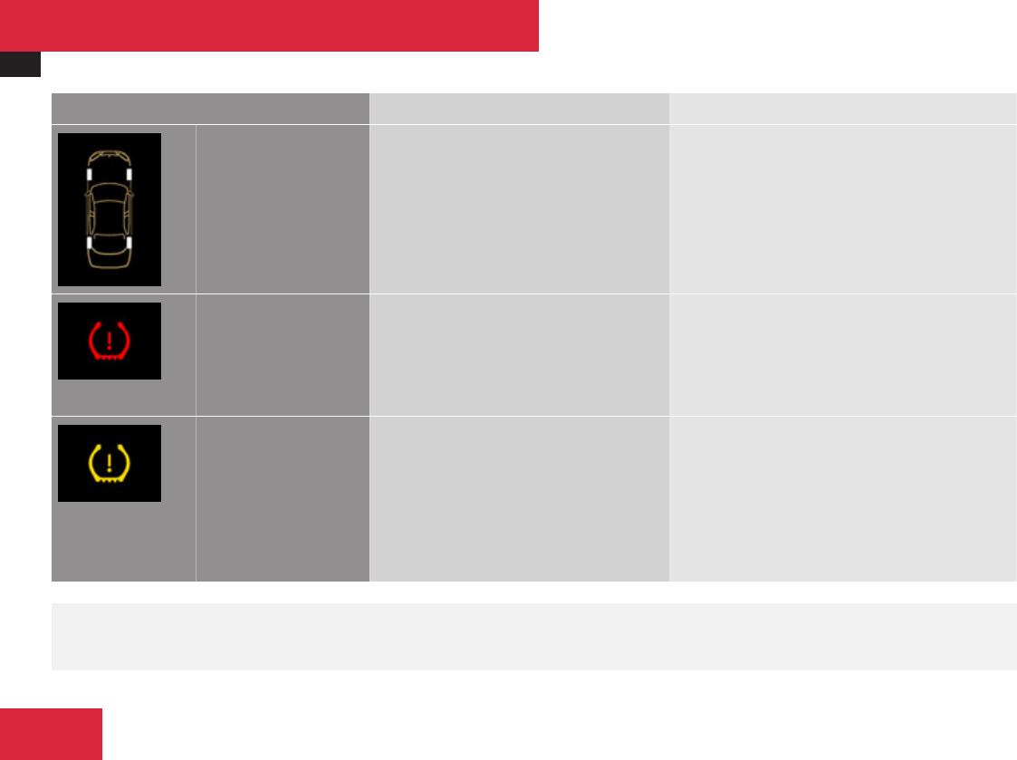
Vehicle status messages in the multifunction display
546
Display messages Possible cause/consequence Possible solution
Tire Pressure
Please Rectify
The pressure is too low in one or more
tires.
Or the tire pressures of the individual
wheels differ too radically from one
another.
XCheck and correct tire inflation pressure as
required (Y page 458).
Tire Press.
Warning
Caution
Tire Malfunction
One or more tires are deflating. XCarefully bring the vehicle to a halt, avoiding
abrupt steering and braking maneuvers.
XEngage the electronic parking brake.
XIf necessary, change the wheel
(Y page 571).
Check
Tire Pressure
The tire pressure is too low in one or more
tires.
XCarefully bring the vehicle to a halt, avoiding
abrupt steering and braking maneuvers.
XEngage the electronic parking brake.
XCheck and correct tire inflation pressure as
required (Y page 458).
XIf necessary, change the wheel
(Y page 571).
GWarning!
Do not drive with a flat tire. A flat tire affects the ability to steer or brake the vehicle. You may lose control of the vehicle. Continued driving
with a flat tire will cause excessive heat build-up and possibly a fire.
Practical hints

Vehicle status messages in the multifunction display
547
GWarning!
Follow recommended tire inflation pressures.
Do not underinflate tires. Underinflated tires wear excessively and/or unevenly, adversely affect handling and fuel economy, and are more
likely to fail from being overheated.
Do not overinflate tires. Overinflated tires can adversely affect handling and ride comfort, wear unevenly, increase stopping distance, and
result in sudden deflation (blowout) because they are more likely to become punctured or damaged by road debris, potholes etc.
Practical hints
Z

What to do if …
548
What to do if …
Lamps in instrument cluster
Notes
If any of the following lamps in the instrument
cluster fails to come on during the bulb self-
check when switching on the ignition, have
the respective bulb checked and replaced if
necessary.
When you switch on the ignition, all lamps
(except high-beam headlamp indicator lamp,
and turn signal indicator lamps unless
activated) in the instrument cluster come on.
If a lamp in the instrument cluster fails to
come on when the ignition is switched on,
have it checked and replaced if necessary.
Practical hints

What to do if …
549
Brake
Problem Possible cause/consequence Suggested solutions
-The yellow ABS indicator
lamp comes on while the
engine is running.
The ABS has detected a
malfunction and switched off.
The BAS, ESP®, EBP and PRE-
SAFE® are also switched off (see
messages in multifunction
display).
The brake system is still
functioning normally but without
the systems specified above
available.
If the ABS control unit is
malfunctioning, other systems
such as the Parktronic, the
DISTRONIC Plus, the navigation
system or the automatic
transmission may also be
malfunctioning.
XContinue driving with added caution. Wheels may lock during hard
braking, reducing steering capability.
XRead and observe messages that may appear in the multifunction
display (Y page 495).
XHave the system checked at an authorized Mercedes-Benz Center
as soon as possible.
Failure to follow these instructions increases the risk of an accident.
-The yellow ABS indicator
lamp comes on while the
engine is running.
The ABS has switched off due to
insufficient power supply.
The battery might not be charged
sufficiently.
When the voltage is above the required value again, the ABS is
operational again and the ABS indicator lamp should go out.
XIf the ABS indicator lamp does not go out: Have the alternator and
the battery checked.
Practical hints
Z

What to do if …
550
Problem Possible cause/consequence Suggested solutions
-
v
The yellow ABS malfunction
indicator lamp and the yellow
ESP® warning lamp come on
while the engine is running and an
acoustic warning sounds.
The brake system is still
functioning normally but due to a
malfunction, the ABS, the BAS,
the EBP, the ESP® and
PRE-SAFE® are unavailable.
XContinue driving with added caution. Wheels may lock during hard
braking, reducing steering capability.
XRead and observe messages in the multifunction display
(Y page 495).
XHave the system checked at an authorized Mercedes-Benz Center
as soon as possible.
Failure to follow these instructions increases the risk of an accident.
; (USA only)
3 (Canada only)
-
v
The red brake warning lamp
comes on while driving. In
addition, the yellow ABS
malfunction indicator lamp, and
the yellow ESP® warning lamp
come on and an acoustic warning
sounds.
The Electronic Brake
Proportioning (EBP) switched off
due to a malfunction.
The ABS, the BAS, the ESP® and
PRE-SAFE® are also switched off.
The brake system continues to
function normally, but without
electronic support.
XContinue driving with added caution. Wheels may lock during hard
braking, reducing steering capability.
XRead and observe messages that may appear in the multifunction
display (Y page 495).
XHave the system checked at an authorized Mercedes-Benz Center
as soon as possible.
Failure to follow these instructions increases the risk of an accident.
0 (USA only)
! (Canada only)
The red indicator lamp for the
electronic parking brake flashes
and/or the yellow warning lamp
for the electronic parking brake is
on.
The electronic parking brake is
malfunctioning or defective.
XRead and observe messages that may appear in the multifunction
display (Y page 495).
XHave the system checked at an authorized Mercedes-Benz Center
as soon as possible.
Practical hints

What to do if …
551
Problem Possible cause/consequence Suggested solutions
; (USA only)
3 (Canada only)
The red brake warning lamp
comes on while the engine is
running and an acoustic warning
sounds.
There is insufficient brake fluid in
the reservoir.
XRisk of accident! Do not drive any further. Stop the vehicle in a safe
location as soon as it is safe to do so.
XEngage the electronic parking brake.
XRead and observe messages that may appear in the multifunction
display (Y page 495).
XContact an authorized Mercedes-Benz Center. Do not add brake
fluid! This will not solve the problem.
GWarning!
Driving with the brake warning lamp illuminated can result in an accident. Have your brake system checked immediately if the brake warning
lamp stays on. Do not add brake fluid before checking the brake system.
Overfilling the brake fluid reservoir can result in spilling brake fluid on hot engine parts and the brake fluid catching fire. You can be seriously
burned.
! If you find that the brake fluid in the brake fluid reservoir has fallen to the minimum mark or below, have the brake system checked for
brake pad thickness and leaks.
Practical hints
Z

What to do if …
552
Safety systems
Problem Possible cause/consequence Suggested solutions
<The red seat belt telltale
comes on for a maximum
of 6 seconds after starting
the engine.
The seat belt telltale reminds you
and your passengers to fasten
your seat belts before driving off.
XFasten your seat belts.
Regardless of whether the seat belts are fastened or not, the seat
belt telltale always comes on and remains lit for 6 seconds after
starting the engine.
<You hear a warning chime
for a maximum of
6 seconds after starting
the engine.
You have forgotten to fasten your
seat belt.
XFasten your seat belt.
The warning chime stops sounding.
<The red seat belt telltale
comes on while the vehicle
is standing still and the
engine is running or during
driving.
You and/or your front passenger
have forgotten to fasten your seat
belts.
XFasten your seat belts.
The seat belt telltale goes out.
There are items placed on the
front passenger seat and
therefore the system senses the
front passenger seat as being
occupied.
XRemove the items from the front passenger seat and put them in
a safe place.
The seat belt telltale goes out.
Practical hints

What to do if …
553
Problem Possible cause/consequence Suggested solutions
<During driving the red seat
belt telltale flashes and
you additionally hear an
intermittent warning
chime with increasing
intensity.
The vehicle’s speed once
exceeded 15 mph (25 km/h) and
you and/or your front passenger
have forgotten to fasten your seat
belts.
XFasten your seat belts.
The seat belt telltale goes out and the warning chime stops
sounding.
There are items placed on the
front passenger seat and
therefore the system senses the
front passenger seat as being
occupied.
XRemove the items from the front passenger seat and put them in
a safe place.
The seat belt telltale goes out and the warning chime stops
sounding.
iAfter 60 seconds with an unfastened seat belt the warning chime stops sounding and the seat belt telltale illuminates continuously. The
seat belt telltale will only go out if both, the driver and front passenger’s seat belt are fastened, or the vehicle is standing still and a front
door is opened.
Problem Possible cause/consequence Suggested solutions
=The red SRS indicator
lamp comes on while
driving.
There is a malfunction in the
restraint systems. The air bags or
Emergency Tensioning Devices
(ETDs) could deploy
unexpectedly or fail to activate in
an accident.
XDrive with added caution to the nearest authorized Mercedes-Benz
Center.
GWarning!
In the event a malfunction of the SRS is indicated as outlined above, the SRS may not be operational.
Practical hints
Z

What to do if …
554
For your safety, we strongly recommend that you contact an authorized Mercedes-Benz Center immediately to have the system checked.
Otherwise the SRS may not be activated when needed in an accident, which could result in serious or fatal injury, or it might deploy
unexpectedly and unnecessarily which could also result in injury.
Problem Possible cause/consequence Suggested solutions
vThe yellow ESP® warning
lamp comes on while the
engine is running.
The ESP® has been switched off.
Risk of accident!
When the ESP® is switched off it
will not stabilize the vehicle if the
system recognizes that the
vehicle starts to skid or that a
wheel is spinning.
The cruise control is deactivated
and cannot be switched on.
XSwitch the ESP® back on.
Exceptions: (Y page 74).
XIf leaving the ESP® switched off, adapt your speed and driving to
the prevailing road and weather conditions.
XIf the ESP® cannot be switched back on: Have the system checked
at an authorized Mercedes-Benz Center as soon as possible.
vThe yellow ESP® warning
lamp comes on while the
engine is running.
The ESP® is not operational due
to a malfunction.
Risk of accident!
The cruise control is deactivated
and cannot be switched on.
XRead and observe additional messages that may appear in the
multifunction display.
XContinue driving with added caution.
XAdapt your speed and driving to the prevailing road and weather
conditions.
XHave the system checked at an authorized Mercedes-Benz Center
as soon as possible.
Practical hints

What to do if …
555
Problem Possible cause/consequence Suggested solutions
vThe yellow ESP® warning
lamp flashes while driving.
The ESP® or Electronic Traction
System (ETS/4-ETS) has come
into operation because of
detected traction loss in at least
one tire.
The cruise control and the
DISTRONIC Plus are deactivated.
XWhen driving off, apply as little throttle as possible.
XWhile driving, ease up on the accelerator pedal.
XAdapt your speed and driving to the prevailing road and weather
conditions.
XDo not deactivate the ESP®.
Exceptions: (Y page 74).
Failure to follow these instructions increases the risk of an accident.
Driving systems
Problem Possible cause/consequence Suggested solutions
lPRE-SAFE® Brake: The red
distance warning lamp
comes on while driving.
You are too close to the vehicle in
front of you to maintain selected
speed.
XApply the brakes immediately to increase the following distance.
lDISTRONIC Plus or
PRE-SAFE® Brake: The red
distance warning lamp
comes on while driving
and an acoustic warning
sounds.
You are gaining too rapidly on the
vehicle ahead of you or
DISTRONIC Plus or PRE-SAFE®
Brake has recognized a
stationary obstacle on your
probable line of travel.
XApply the brakes immediately.
XCarefully observe the traffic situation. You may need to brake or
maneuver to avoid hitting an obstacle.
Practical hints
Z


What to do if …
557
Engine
Problem Possible cause/consequence Suggested solutions
±
The yellow engine malfunction
indicator lamp comes on when
the engine is running.
There may be a malfunction in:
RThe fuel management system
RThe ignition system
RThe emission control system
RSystems which affect
emissions
Such malfunctions may result in
excessive emissions values and
may switch the engine to limp-
home (emergency operation)
mode.
XHave the vehicle checked as soon as possible at an authorized
Mercedes-Benz Center.
iSome states may by law require you to visit a workshop as soon
as the engine malfunction indicator lamp comes on. Check local
requirements.
±
The yellow engine malfunction
indicator lamp comes on when
the engine is running.
A loss of pressure has been
detected in the fuel system. The
fuel cap may not be closed
properly or the fuel system may
be leaky.
XCheck the fuel cap (Y page 441).
XIf it is not closed properly: Close the fuel cap.
XIf it is closed properly: Have the fuel system checked by an
authorized Mercedes-Benz Center.
Practical hints
Z

What to do if …
558
Tires
Problem Possible cause/consequence Suggested solutions
HUSA only:
Combination low tire
pressure telltale/TPMS
malfunction telltale for the
Advanced TPMS
illuminates continuously.
Canada only:
Low tire pressure telltale
for the Advanced TPMS
illuminates continuously.
The Advanced TPMS detects a
loss of pressure in at least one
tire.
XCarefully bring the vehicle to a halt, avoiding abrupt steering and
braking maneuvers. Observe the traffic situation around you.
XRead and observe messages in the multifunction display
(Y page 495).
If the tire inflation pressure in the respective tire(s) has (have) been
corrected, the combination low tire pressure/TPMS malfunction
telltale goes out after a few minutes of driving.
HUSA only:
Combination low tire
pressure telltale/TPMS
malfunction telltale for the
Advanced TPMS flashes
60 seconds and then stays
illuminated.
There is a malfunction in the
Advanced TPMS.
XRead and observe messages in the multifunction display
(Y page 495).
XHave the Advanced TPMS checked by an authorized Mercedes-
Benz Center.
After the malfunction has been remedied, the combination low tire
pressure/TPMS malfunction telltale goes out after a few minutes of
driving.
GWarning!
Each tire, including the spare (if provided),
should be checked every other week when
cold and inflated to the inflation pressure
recommended by the vehicle manufacturer
on the Tire and Loading Information placard
on the driver’s door B-pillar or, if available,
the tire inflation pressure label on the inside
of the fuel filler flap. If your vehicle has tires
of a different size than the size indicated on
the vehicle placard or the tire inflation
pressure label, you should determine the
proper tire inflation pressure for those tires.
As an added safety feature, your vehicle has
been equipped with a tire pressure
monitoring system (TPMS) that illuminates
a low tire pressure telltale when one or
Practical hints

What to do if …
559
more of your tires are significantly
underinflated. Accordingly, when the low
tire pressure telltale illuminates, you should
stop and check your tires as soon as
possible, and inflate them to the proper
pressure. Driving on a significantly
underinflated tire causes the tire to
overheat and can lead to tire failure.
Underinflation also reduces fuel efficiency
and tire tread life, and may affect the
vehicle’s handling and stopping ability.
Please note that the TPMS is not a
substitute for proper tire maintenance, and
it is the driver’s responsibility to maintain
correct tire pressure, even if underinflation
has not reached the level to trigger
illumination of the TPMS low tire pressure
telltale.
USA only:
Your vehicle has also been equipped with a
TPMS malfunction indicator to indicate
when the system is not operating properly.
The TPMS malfunction indicator is
combined with the low tire pressure
telltale. When the system detects a
malfunction, the telltale will flash for
approximately 1 minute and then remain
continuously illuminated. This sequence
will continue upon subsequent vehicle
start-ups as long as the malfunction exists.
When the malfunction indicator is
illuminated, the system may not be able to
detect or signal low tire pressure as
intended.
TPMS malfunctions may occur for a variety
of reasons, including the installation of
replacement or alternate tires or wheels on
the vehicle that prevent the TPMS from
functioning properly. Always check the
TPMS malfunction telltale after replacing
one or more tires or wheels on your vehicle
to ensure that the replacement or alternate
tires and wheels allow the TPMS to
continue to function properly.
Lamp in center console
Problem Possible cause/consequence Suggested solutions
59
The front passenger front air bag
off indicator lamp illuminates and
remains illuminated with the
weight of a typical adult or
someone larger than a small
individual on the front passenger
seat.
The system is malfunctioning. XHave the system checked as soon as possible at an authorized
Mercedes-Benz Center.
XRead and observe messages in the multifunction display and follow
corrective steps (Y page 495).
Practical hints
Z

What to do if …
560
GWarning!
If the 59 indicator lamp
illuminates and remains illuminated with
the weight of a typical adult or someone
larger than a small individual on the front
passenger seat, do not have any passenger
use the front passenger seat until the
system has been repaired.
Problem Possible cause/consequence Suggested solutions
59
The front passenger front air bag
off indicator lamp does not
illuminate and/or does not
remain illuminated with the
weight of a typical 12-month-old
child in a standard child restraint
or less on the front passenger
seat.
The system is malfunctioning. XMake sure there is nothing between seat cushion and child seat
and check installation of the child seat.
XMake sure no objects applying supplemental weight onto the seat
are present.
XMake sure no objects which apply forces to the seat are present
(e.g. objects such as books, briefcases etc. lodged behind or
around the seat, head restraints pushing against roof etc.). The
system may recognize such forces as supplemental weight.
XIf the front passenger front air bag off indicator lamp remains out,
have the system checked as soon as possible at an authorized
Mercedes-Benz Center. Do not transport a child on the front
passenger seat until the system has been repaired.
XRead and observe messages in the multifunction display and follow
corrective steps (Y page 495).
GWarning!
If the 59 indicator lamp does
not illuminate or remains out with the
weight of a typical 12-month-old child in a
standard child restraint or less on the front
passenger seat, do not transport a child on
the front passenger seat until the system
has been repaired.
Practical hints
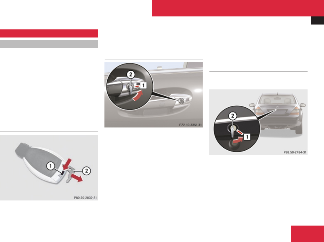
Unlocking/locking manually
561
Unlocking/locking manually
Unlocking the vehicle
If you cannot unlock the vehicle with the
SmartKey or with KEYLESS-GO, unlock the
driver’s door and the trunk using the
mechanical key.
iUnlocking the vehicle with the
mechanical key and opening the driver’s
door or the trunk will trigger the anti-theft
alarm system.
To cancel the alarm, insert the SmartKey in
the starter switch.
Removing the mechanical key
1Mechanical key locking tab
2Mechanical key
XMove locking tab 1 in direction of arrow.
XSlide mechanical key 2 out of the housing.
Unlocking the driver’s door
$Unlocking
2Mechanical key
XInsert mechanical key 2 into the driver’s
door lock until it stops.
XTurn mechanical key 2 counterclockwise
to position $.
XPull the door handle past the resistance
point until the locking knob moves up.
The driver’s door is unlocked.
XPull the door handle once more to open the
driver’s door.
XTurn mechanical key 2 back and remove
it from the driver’s door lock.
Unlocking the trunk
A minimum height clearance of 5.9 ft (1.8 m)
is required to open the trunk lid.
$Unlocking
2Mechanical key
XInsert mechanical key 2 into the trunk lid
lock until it stops.
XTurn mechanical key 2 all the way
counterclockwise to position $.
Practical hints
Z

Resetting activated head restraints
562
! The trunk lid swings open upwards
automatically. Always make sure there is
sufficient overhead clearance.
XTurn mechanical key 2 back and remove
it from the trunk lid lock.
Locking the vehicle
If you cannot lock the vehicle with the
SmartKey or with KEYLESS-GO, lock it as
follows:
XClose the front passenger door, the right
rear door and the trunk.
iIf you cannot close the trunk with the
remote trunk opening/closing switch,
lower the trunk lid manually and close it
with hands placed flat on the trunk lid until
it is engaged in its lock.
XOpen the driver’s door and the rear left
door.
XPress the central locking switch
(Y page 301).
The locking knobs of the front passenger
door and the rear doors move down.
XIf the vehicle battery is disconnected or
drained: Press down the locking knobs of
the front passenger door and the rear doors
manually.
XExit the vehicle.
XCheck whether the trunk is locked.
XIf it is not locked, lock it with the
mechanical key (Y page 306).
Except for the driver’s door, the vehicle
should now be locked.
XClose the driver’s door.
XEnter the vehicle through the rear left door.
XPress down the locking knob of the driver’s
door.
! To prevent inadvertent lockout, make
sure to have the SmartKey with you before
proceeding with the next step. The next
step will lock the vehicle.
XExit the vehicle.
XClose the rear left door.
The vehicle is locked.
iThis procedure does not arm the anti-
theft alarm system, nor does it lock the fuel
filler flap.
Resetting activated head restraints
If the active head restraints have been
triggered in a rear-end collision, the active
head restraints must be reset.
You can tell that the active head restraints
have been triggered when they have been
moved forward and cannot be adjusted.
GWarning!
For safety reasons, have the active head
restraints checked at an authorized
Mercedes-Benz Center after a rear-end
collision.
GWarning!
When pushing back the head restraint
cushion, make sure your fingers do not
become caught between the head restraint
cushion and the cover. Failing to do so may
lead to injury.
! Be careful not to damage upholstery.
iPressing the head restraint cushion back
requires high force. If you encounter
difficulties when pushing the head restraint
back, please have the procedure
Practical hints
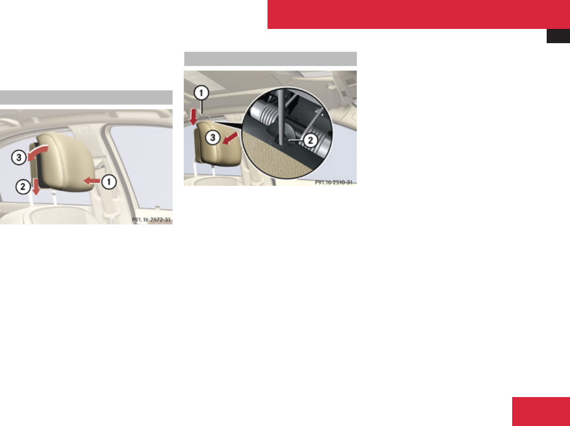
Resetting activated head restraints
563
performed at an authorized Mercedes-Benz
Center.
Head restraints (standard)
1Fold back
2Push down
3Push back
XPush the head restraint cushion by the
bottom, back as far as it will go 1.
XPush the head restraint cushion down into
the guide as far as it will go 2.
XFold the head restraint cushion by the top,
back firmly until it engages 3.
XRepeat this procedure on the active head
restraint for the second front seat.
Comfort head restraints
1Reset tool
2Rectangular opening
3Active head restraint cushion
XTake reset tool 1 out of the Mercedes-
Benz literature pouch.
XGuide reset tool 1 into rectangular
opening 2 between active head restraint
cushion and head restraint cover.
XPress reset tool 1 downward in direction
of arrow until you hear the head restraint
release mechanism audibly engage.
XPull out reset tool 1.
XFirmly press the active head restraint
cushion backward towards the head
restraint cover in direction of arrow 3 until
it engages.
XRepeat this procedure for the second front
seat.
XAfter resetting the active head restraints
store reset tool 1 in the Mercedes-Benz
literature pouch.
For information on active head restraints, see
“Active head restraints” (Y page 60).
For information on head restraint adjustment,
see “Seats” (Y page 309).
Practical hints
Z
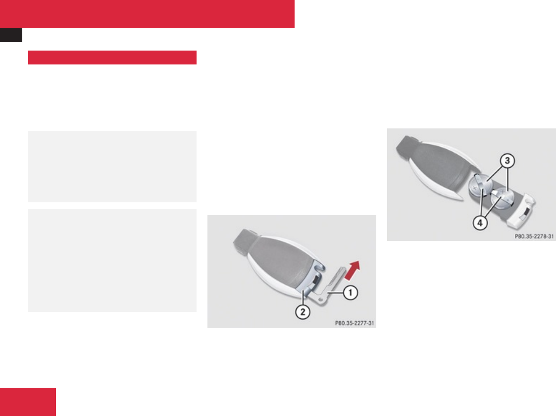
Replacing SmartKey batteries
564
Replacing SmartKey batteries
If the batteries in the SmartKey are
discharged, the vehicle can no longer be
locked or unlocked. It is recommended to
have the batteries replaced at an authorized
Mercedes-Benz Center.
GWarning!
Batteries contain poisonous and corrosive
substances. Therefore, keep the batteries
out of reach of children.
If a battery is swallowed, seek medical help
immediately.
GWarning!
SmartKey batteries contain perchlorate
material, which may require special
handling and regard for the environment.
Check with your local government’s
disposal guidelines. California residents,
see www.dtsc.ca.gov/
HazardousWaste/Perchlorate/
index.cfm.
Batteries contain materials that can harm the
environment if disposed of improperly.
Recycling of batteries is the preferred method
of disposal. Many states/provinces require
sellers of batteries to accept old batteries for
recycling.
When inserting the batteries, make sure they
are clean and free of lint.
When replacing batteries, always replace
both batteries.
iThe required replacement batteries are
available at any authorized Mercedes-Benz
Center.
Replacement batteries: Lithium, type
CR 2025 or equivalent.
XRemove the mechanical key from the
SmartKey (Y page 561).
1Mechanical key
2Battery compartment
XInsert mechanical key 1 into opening.
XPress mechanical key 1 in direction of
arrow.
Battery compartment 2 is unlatched.
XPull battery compartment 2 out of the
SmartKey housing.
3Batteries
4Contact springs
XPull out batteries 3.
XInsert new batteries 3 under contact
springs 4 with the positive terminal (+)
side facing up.
XReturn battery compartment 2 into
SmartKey housing until it locks into place.
Practical hints

Replacing bulbs
565
XSlide mechanical key 1 back into the
SmartKey.
XCheck the operation of the SmartKey as
well as the KEYLESS-GO function.
Replacing bulbs
Safety notes
Safe vehicle operation depends on proper
exterior lighting and signaling to a large
degree.
Correct headlamp adjustment is extremely
important. Have headlamps checked and
readjusted at regular intervals and when a
bulb has been replaced. Contact an
authorized Mercedes-Benz Center for
headlamp adjustment.
GWarning!
Bulbs and bulb sockets can be very hot.
Allow the lamp to cool down before
changing a bulb.
Keep bulbs out of reach of children.
Halogen lamps contain pressurized gas. A
bulb can explode if you:
Rtouch or move it when hot
Rdrop the bulb
Rscratch the bulb
Wear eye and hand protection.
Because of high voltage in Xenon lamps, it
is dangerous to replace the bulb or repair
the lamp and its components. We
recommend that you have such work done
by a qualified technician.
GWarning!
The bulbs in the tail lamps cannot be
replaced individually. The tail lamp bulbs
are under pressure and could explode
during an attempt to replace them.
If the tail lamps are malfunctioning, have
them replaced at an authorized Mercedes-
Benz Center.
iSince replacing bulbs is a technically
highly demanding process, we recommend
to have them replaced at an authorized
Mercedes-Benz Center.
iIf the headlamps or front fog lamps are
fogged up on the inside as a result of high
humidity, driving the vehicle a distance with
the lights on should clear up the fogging.
Practical hints
Z
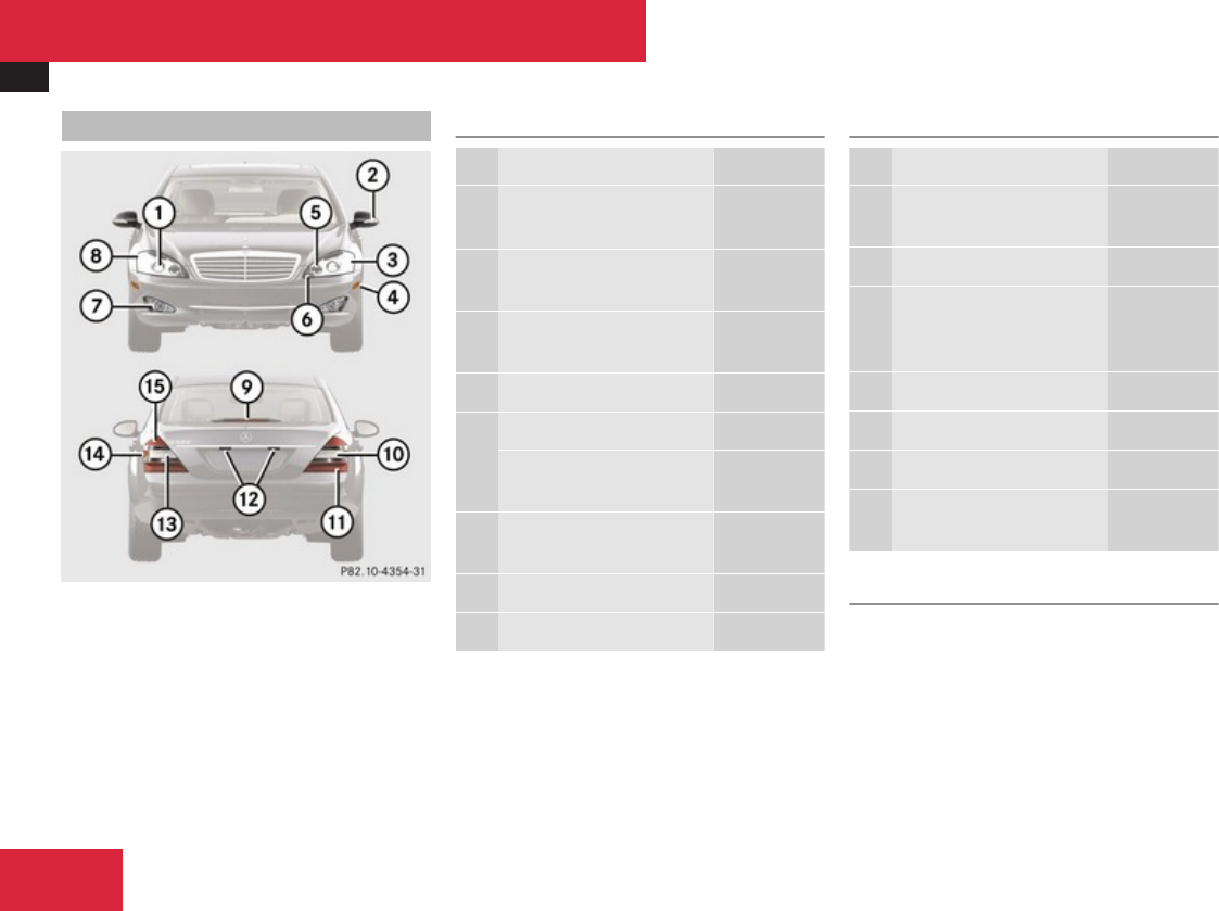
Replacing bulbs
566
Bulbs Front lamps
Lamp Type
1Low- and high-beam
lamp10
D1S-35 W
2Additional turn signal
lamp
LED
3Parking and standing
lamp
W 5 W
4Side marker lamp W 5 W
5High-beam flasher lamp H7 (55 W)
IR emitter (for Night
View Assist)
H11 (55 W)
6Corner-illuminating
lamp
H7 (55 W)
7Front fog lamp H11 (55 W)
8Turn signal lamp PY 24 W
Rear lamps
Lamp Type
9High-mounted brake
lamp
LED
aTurn signal lamp HiP
bBrake lamp, tail lamp,
parking and standing
lamp
LED
cLicense plate lamps W 5 W
dBackup lamp HiP
eSide marker lamp LED
fRear fog lamp (driver’s
side only)
HiP
Notes on bulb replacement
ROnly use 12-volt bulbs of the same type and
with the specified watt rating.
RSwitch the lights off before changing a bulb
to prevent short circuits.
RAlways use a clean lint-free cloth when
handling bulbs.
10 Vehicles with Bi-Xenon headlamps: Low beam and high beam use the same D1S-35 W lamp. Do not replace the Bi-Xenon bulbs yourself. Contact an authorized
Mercedes-Benz Center.
Practical hints
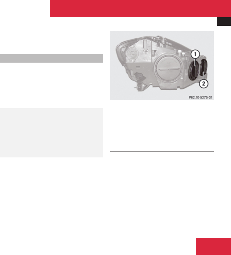
Replacing bulbs
567
RYour hands should be dry and free of oil and
grease.
RIf the newly installed bulb does not come
on, contact an authorized Mercedes-Benz
Center.
iMercedes-Benz recommends using
Longlife (LL) bulbs.
Have the LEDs and bulbs for the following
lamps replaced at an authorized Mercedes-
Benz Center:
RAdditional turn signal lamps in the exterior
rear view mirrors
RBi-Xenon lamps
RFront fog lamps
RFront side marker lamps
RLicense plate lamps
RParking and standing lamps
RFront turn signal lamps
RRear lamps
RHigh-mounted brake lamp
! Do not replace the LEDs yourself. You
could otherwise damage the LEDs or parts
of the vehicle. Only have the LEDs replaced
at an authorized Mercedes-Benz Center.
Replacing bulbs for front lamps
You can change the halogen bulbs for the
following lamps:
RHigh-beam flasher lamp
RCorner-illuminating lamp
RIR emitter lamp
GWarning!
Do not remove the cover for the Bi-Xenon
headlamp. Because of high voltage in
Xenon lamps, it is dangerous to replace the
bulb or repair the lamp and its components.
It is recommended to have such work done
by a qualified technician.
Before you start to replace a bulb for a front
lamp, do the following:
XSwitch off the ignition.
XTurn the exterior lamp switch to position
M.
XOpen the hood (Y page 443).
1Housing cover for high-beam flasher bulb
and IR emitter lamp bulb
2Housing cover for corner-illuminating
lamp bulb
Removing and installing washer fluid
reservoir (vehicles with AIRMATIC only)
You must remove the washer fluid reservoir
in order to change the bulbs of the headlamp
on the driver’s side. The washer fluid reservoir
is on the front driver’s side of the engine
compartment.
Practical hints
Z
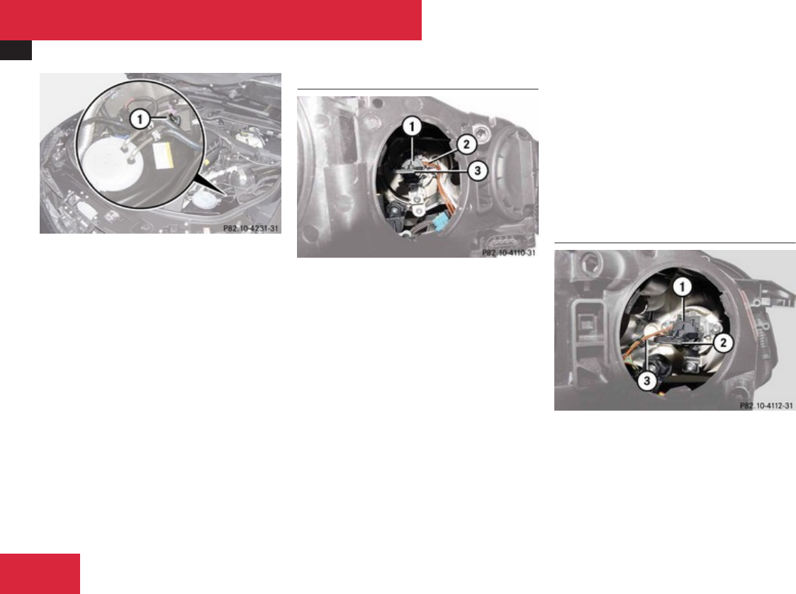
Replacing bulbs
568
Example illustration: S 550
1Retaining screw
Removing
XTurn retaining screw 1 counterclockwise.
XTake washer fluid reservoir out of
mounting.
XPlace washer fluid reservoir to the side and
do not disconnect any wires or cables.
Installing
XGuide washer fluid reservoir into mounting
so that the bottom retaining lug slides into
the rubber sleeve on the longitudinal
member.
XTurn retaining screw 1 clockwise
High-beam flasher bulb
1Bulb holder
2Wire position
3Grip
XTurn housing cover 1 (Y page 567)
counterclockwise and remove it.
XTurn bulb holder 1 counterclockwise until
it disengages
XTake out bulb holder 1.
XTake bulb out of holder 1.
XInsert new bulb into bulb holder 1 and
press it all the way down.
XInsert bulb holder 1 into guide in
headlamp.
The tab of the bulb holder 1 must be
positioned on the upper left-hand side and
wire 2 must point downward and to the
right (driver’s side headlamp) or downward
and to the left (passenger-side headlamp).
XTurn bulb holder 1 clockwise until it
engages and grip 3 is in a horizontal
position.
XAttach housing cover 1 (Y page 567) and
let it audibly engage to close.
Corner-illuminating lamp bulb
1Bulb holder
2Grip
3Wire position
XTurn housing cover 2 (Y page 567)
counterclockwise and remove it.
XTurn bulb holder 1 counterclockwise until
it disengages.
Practical hints
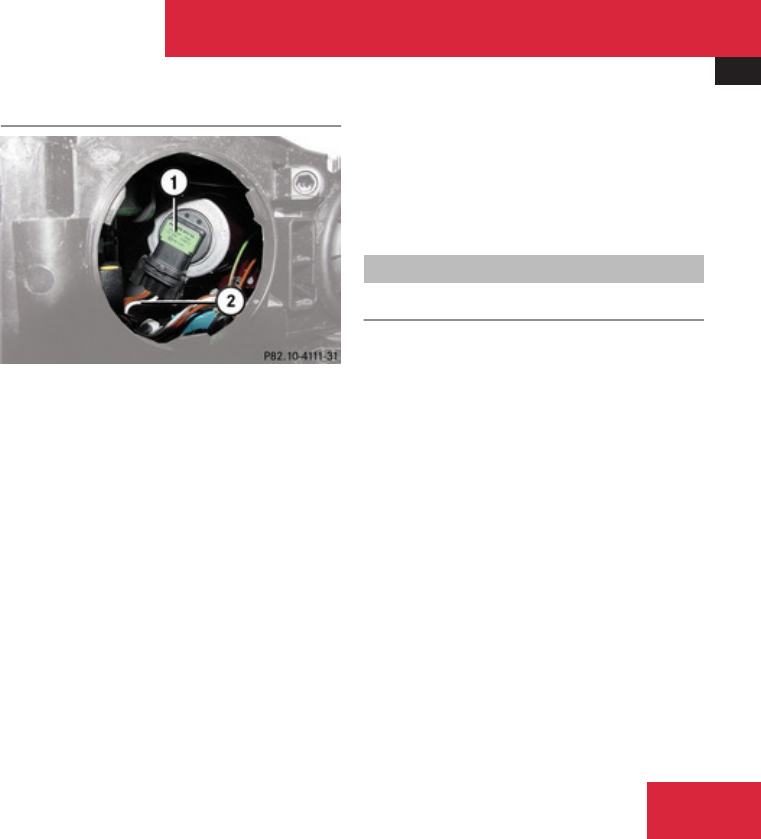
Replacing bulbs
569
XTake out bulb holder 1.
XTake bulb out of holder 1.
XInsert new bulb into bulb holder 1 and
press it all the way down.
XInsert bulb holder 1 into guide in
headlamp.
The tab of the bulb holder 1 must be
positioned on the upper left-hand side and
wire 3 must point downward and to the
left (driver’s side headlamp) or upward and
to the right (passenger-side headlamp).
XTurn bulb holder 1 clockwise until it
engages and grip 2 is in a horizontal
position.
XAttach housing cover 2 (Y page 567) and
let it audibly engage to close.
IR emitter lamp bulb
1Bulb
2Wire position
XTurn cover 1 (Y page 567)
counterclockwise and remove it.
XTurn bulb 1 counterclockwise until it
disengages.
XTake out bulb 1.
XPress both catches on left and right sides
of bulb 1 and disconnect the wire from the
bulb.
XConnect a new bulb 1 to the wire.
XInsert bulb 1 into guide in headlamp.
Wire 2 must point downward and to the
right.
XTurn bulb 1 clockwise until it engages.
Wire 2 now points downward and to the
left.
XAttach housing cover 1 (Y page 567) and
let it audibly engage to close.
Replacing bulbs for rear lamps
Tail lamp unit
The tail lamps are equipped with HiP bulbs
and LEDs. Have them replaced at an
authorized Mercedes-Benz Center.
Practical hints
Z
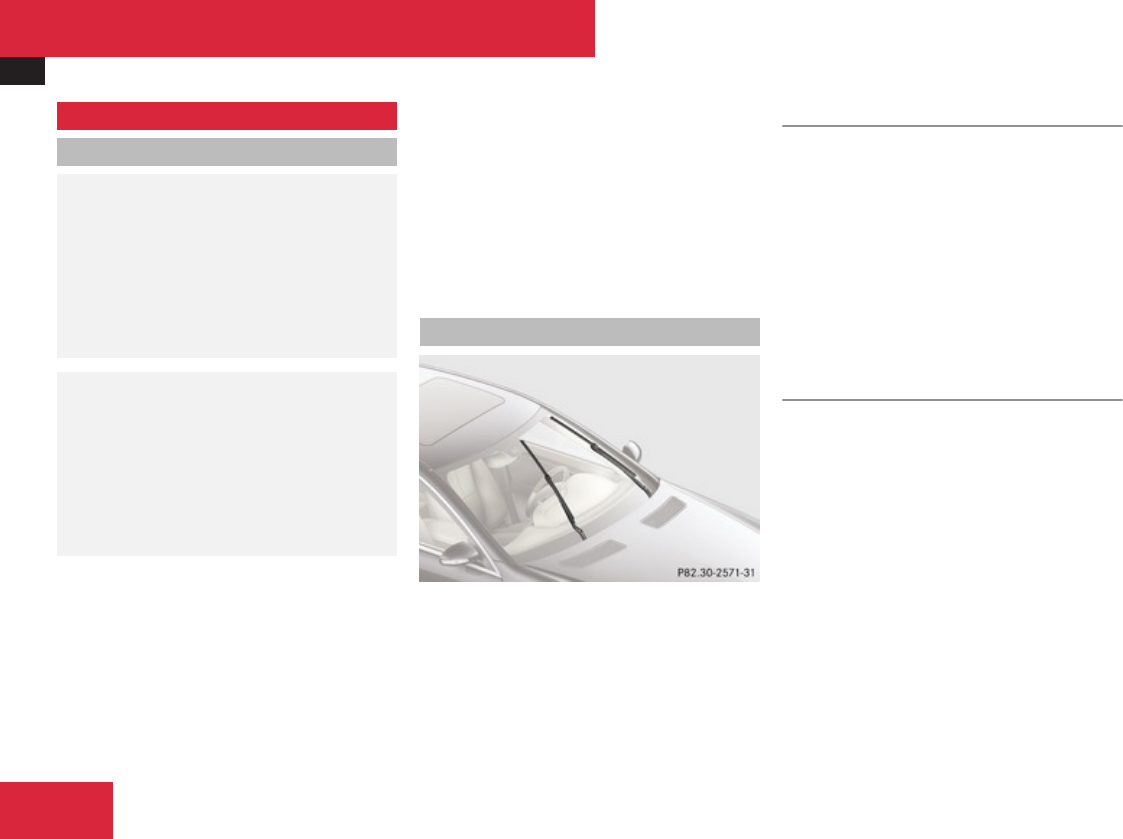
Replacing wiper blades
570
Replacing wiper blades
Safety notes
GWarning!
For safety reasons, switch off wipers and
remove SmartKey from starter switch
(vehicles with KEYLESS-GO: Make sure the
vehicle’s on-board electronics have status
0) before replacing a wiper blade.
Otherwise, the wiper motor could suddenly
turn on and cause injury.
GWarning!
Wiper blades are components that are
subject to wear and tear. Replace the wiper
blades twice a year, preferably in the spring
and fall. Otherwise the windows will not be
properly wiped. As a result, you may not be
able to observe surrounding traffic
conditions and could cause an accident.
! To avoid damage to the hood the wiper
arms should only be folded forward when
in the vertical position.
! Never open the hood when a wiper arm is
folded forward.
Hold on to the wiper when folding a wiper
arm back. If released, the force of the
impact from the tensioning spring could
crack the windshield.
Do not allow a wiper arm to contact the
windshield glass without a wiper blade
inserted.
Mercedes-Benz recommends that you have
this work carried out at an authorized
Mercedes-Benz Center.
Placing wiper arms in vertical position
Wiper arms in vertical position
XMake sure the hood is fully closed.
Vehicles with SmartKey
XTurn the SmartKey in the starter switch to
position 1.
XTurn combination switch to wiper setting
u.
XWith wiper arms in vertical position, turn
the SmartKey in the starter switch to
position 0.
XRemove the SmartKey from the starter
switch.
Vehicles with KEYLESS-GO
XMake sure the vehicle’s on-board
electronics have status 1.
XTurn combination switch to wiper setting
u.
XPress KEYLESS-GO start/stop button
repeatedly until windshield wipers start.
XPress KEYLESS-GO start/stop button when
the wiper arms are in a vertical position.
Practical hints
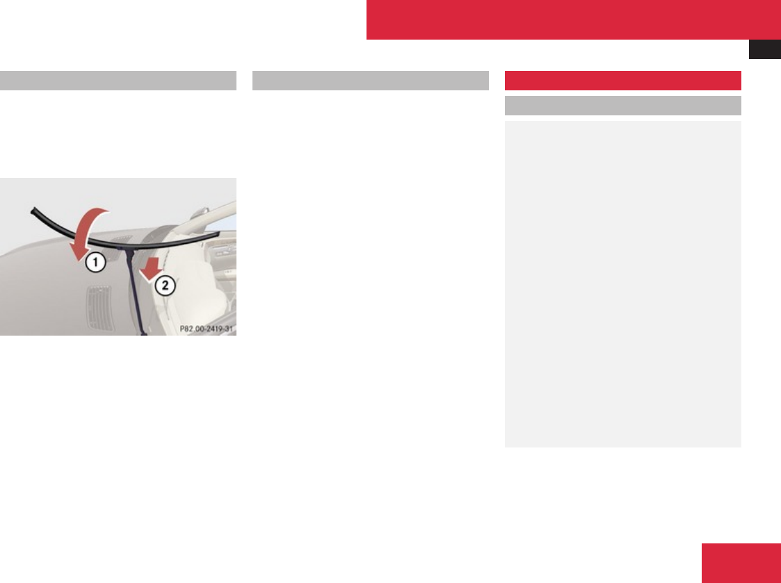
Flat tire
571
Removing wiper blades
! Do not pull on the wiper blade inserts.
They could tear.
XFold the wiper arm forward until it snaps
into place.
1Turning wiper blade
2Removing
XTurn the wiper blade in direction of arrow
1.
XSlide the wiper blade sideways out of the
retainer in the direction of arrow 2.
Installing wiper blades
XSlide the wiper blade onto wiper arm until
it locks in place.
XRotate the wiper blade into position parallel
to the wiper arm.
XFold the wiper arm backward to rest on the
windshield.
Make sure you hold on to the wiper when
folding the wiper arm back.
! Make sure the wiper blades are properly
installed. Improperly installed wiper blades
may cause windshield damage.
Flat tire
Safety notes
GWarning!
The dimensions of the spare wheel are
different from those of the road wheels. As
a result, the vehicle handling
characteristics change when driving with a
spare wheel mounted. Adapt your driving
style accordingly.
The spare wheel is for temporary use only.
When driving with spare wheel mounted,
ensure proper tire inflation pressure and do
not exceed a vehicle speed of 50 mph
(80 km/h).
Contact the nearest authorized Mercedes-
Benz Center as soon as possible to have the
spare wheel replaced with a regular road
wheel.
Never operate the vehicle with more than
one spare wheel mounted.
Do not switch off the ESP® when a spare
wheel is mounted.
Practical hints
Z

Flat tire
572
Preparing the vehicle
XPark the vehicle in a safe distance from
moving traffic on a hard, flat surface when
possible.
XTurn on the hazard warning flasher.
XTurn the steering wheel so that the front
wheels are in a straight-ahead position.
XEngage the electronic parking brake.
XShift the automatic transmission into park
position P.
XTurn off the engine.
XRemove the SmartKey from the starter
switch.
or
XVehicles with KEYLESS-GO: Open the
driver’s door (this puts the starter switch in
position 0, same as with the SmartKey
removed from the starter switch). The
driver’s door can then be closed again.
Open doors only when conditions are safe
to do so.
XVehicles with KEYLESS-GO: Remove the
KEYLESS-GO start/stop button from the
starter switch.
XHave any passenger exit the vehicle at a
safe distance from the roadway. Open
doors only when conditions are safe to do
so.
Mounting the spare wheel
Introduction
XPrepare the vehicle as described
(Y page 572).
XTake the following out of the vehicle:
Rspare wheel
Rjack
Rvehicle tool kit
For information on where to find the
respective items, see “Where will I
find ...?” (Y page 492) and (Y page 494).
Lifting the vehicle
GWarning!
When jacking up the vehicle, only use the
jack which has been specifically approved
by Mercedes-Benz for your vehicle.
The jack is designed exclusively for jacking
up the vehicle at the jack take-up brackets
built into both sides of the vehicle. Make
sure the jack arm is fully seated in the jack
take-up bracket. The jack must always be
vertical when in use, especially on inclines
or declines.
The jack is intended only for lifting the
vehicle briefly for wheel changes. It is not
suited for performing maintenance work
under the vehicle. To help avoid personal
injury, use the jack only to lift the vehicle
during a wheel change.
Never get beneath the vehicle while it is
supported by the jack. Keep hands and feet
away from the area under the lifted vehicle.
Always lower the vehicle onto sufficient
capacity jackstands before working under
the vehicle.
Always firmly set the parking brake and
block the wheels with wheel chocks or
other sizeable objects before raising the
vehicle with the jack. Do not disengage the
parking brake while the vehicle is raised.
Make sure that the ground on which the
vehicle is standing and where you place the
jack is solid, level and not slippery. If
necessary, use a large underlay. On
slippery surfaces, such as tiled floors, you
should use a non-slip underlay, for example
a rubber mat.
Do not use wooden blocks or similar
objects to support the jack. Otherwise the
Practical hints
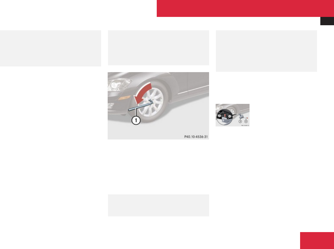
Flat tire
573
jack may not be able to achieve its load-
bearing capacity if it is not at its full height.
Never start the engine when the vehicle is
raised.
Also observe the notes on the jack.
XPrevent the vehicle from rolling away by
blocking wheels with wheel chocks or other
sizeable objects.
One wheel chock is included with the
vehicle tool kit (Y page 492). For
information on setting up the collapsible
wheel chock, see (Y page 493).
When changing wheel on a level surface:
XPlace the wheel chock in front of and
another wheel chock or other sizeable
object behind the wheel that is diagonally
opposite to the wheel being changed.
Always try lifting the vehicle using the jack on
a level surface. However, should
circumstances require you to do so on a hill,
place the wheel chock and another sizeable
object as follows:
XPlace wheel chocks or other sizeable
objects on the downhill side blocking both
wheels of the axle not being worked on.
GWarning!
Only jack up the vehicle on level ground or
on slight inclines/declines. Otherwise, the
vehicle could fall off the jack and injure you
or others.
1Wheel wrench
XOn wheel to be changed, loosen but do not
yet remove the wheel bolts (approximately
one full turn with wrench 1).
The jack take-up brackets are located directly
behind the front wheel housings and in front
of the rear wheel housings.
GWarning!
The jack is designed exclusively for jacking
up the vehicle at the jack take-up brackets.
Make sure the jack arm is fully seated in the
jack take-up bracket.
If you do not position the jack correctly in
the jack take-up bracket, the vehicle can
fall off the jack and seriously or fatally injure
you or others.
! Do not position the jack on the body of
the vehicle, as this may cause damage to
the vehicle.
2Take-up bracket
3Jack
4Crank
XPlace jack 3 on firm ground.
XPosition jack 3 under take-up bracket
2 so that it is always vertical as seen from
the side, even if the vehicle is parked on an
incline.
Practical hints
Z
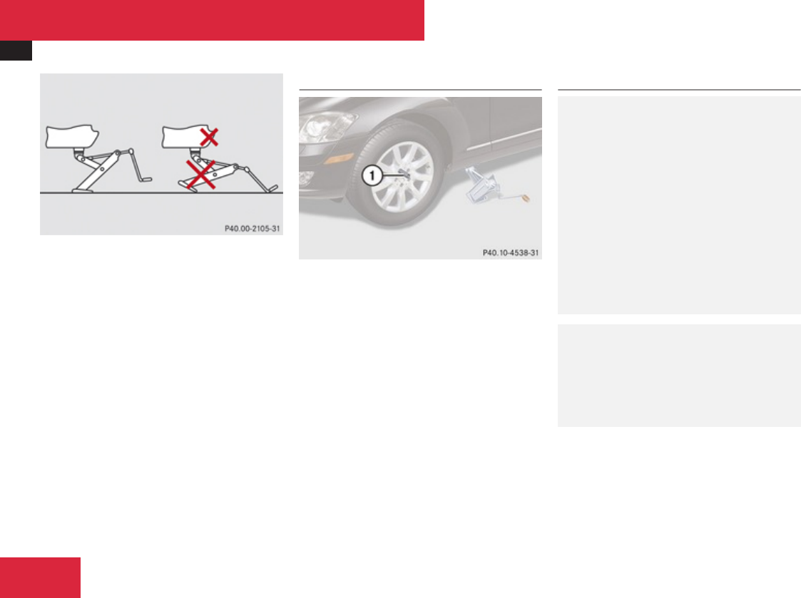
Flat tire
574
XTurn crank 4 clockwise until jack 3 is
fully seated in take-up bracket 2 and the
jack base evenly meets the ground.
XJack up the vehicle until the wheel is a
maximum of 1.2 in (3 cm) from the ground.
Removing the wheel
1Alignment bolt
XUnscrew uppermost wheel bolt and remove
it.
XReplace this wheel bolt with alignment bolt
1 supplied with the vehicle tool kit.
XRemove the remaining bolts.
! Do not place wheel bolts in sand or dirt.
This could result in damage to the wheel
bolts and wheel hub threads.
XRemove the wheel.
Attaching the spare wheel
GWarning!
Always replace wheel bolts that are
damaged or rusted.
Never apply oil or grease to wheel bolts.
Damaged wheel hub threads should be
repaired immediately. Do not continue to
drive under these circumstances! Contact
an authorized Mercedes-Benz Center or
call Roadside Assistance.
Incorrect wheel bolts or improperly
tightened wheel bolts can cause the wheel
to come off. This could cause an accident.
Be sure to use the correct wheel bolts.
GWarning!
Only use genuine Mercedes-Benz wheel
bolts. Other wheel bolts may come loose.
Do not tighten the wheel bolts when the
vehicle is raised. Otherwise the vehicle
could fall off the jack.
Practical hints
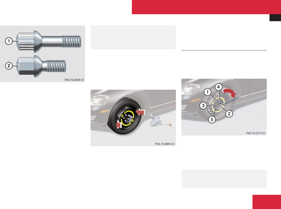
Flat tire
575
1Wheel bolt for light alloy rims and
Minispare wheel with light alloy rim
2Wheel bolt for Minispare wheel with steel
rim (located in trunk with Minispare
wheel)
! Wheel bolts 1 must be used when
mounting the Minispare wheel with light
alloy rim. The use of any wheel bolts other
than wheel bolts 1 for the Minispare wheel
with light alloy rim will damage the vehicle’s
brakes.
Wheel bolts 2 must be used when
mounting the Minispare wheel with steel
rim. The use of any wheel bolts other than
wheel bolts 2 for the Minispare wheel with
steel rim will damage the vehicle’s brakes.
GWarning!
Make sure to use the original length wheel
bolts when remounting the original wheel
after it has been repaired.
XClean contact surfaces of wheel and wheel
hub.
! To avoid paint damage, place wheel flat
against hub and hold it there while
installing first wheel bolt.
XGuide the spare wheel onto the alignment
bolt and push it on.
XInsert the wheel bolts and tighten them
slightly.
XUnscrew the alignment bolt.
XInstall last wheel bolt and tighten it slightly.
Lowering the vehicle
XLower the vehicle by turning crank
counterclockwise until the vehicle is
resting fully on its own weight.
XRemove the jack.
1 – 5Wheel bolts
XTighten the five wheel bolts evenly,
following the diagonal sequence illustrated
(1 to 5), until all bolts are tight. Observe
a tightening torque of 110 lb-ft (150 Nm).
GWarning!
Have the tightening torque checked after
changing a wheel. The wheels could come
Practical hints
Z
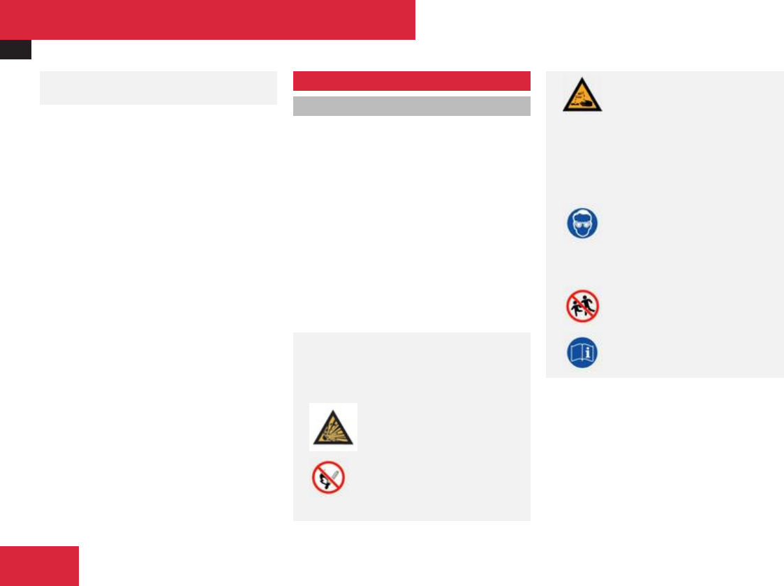
Battery
576
loose if they are not tightened to a torque
of 110 lb-ft (150 Nm).
XFully collapse the jack, with handle folded
in (storage position), see (Y page 493).
XStore the jack and the other vehicle tools
in the designated storage space.
For information on storing the spare wheel
after it has been replaced by a regular road
wheel, see (Y page 494).
iDo not restart the tire inflation pressure
monitor until a full size wheel/tire with
functioning sensor has been placed back
into service on the vehicle.
Battery
Safety notes
A battery should always be sufficiently
charged in order to achieve its rated service
life. Refer to Maintenance Booklet for battery
maintenance intervals.
If you use your vehicle mostly for short-
distance trips, you will need to have the
battery charge checked more frequently.
When replacing a battery, always use a
battery approved by Mercedes-Benz.
If you do not intend to operate your vehicle
for an extended period of time, contact an
authorized Mercedes-Benz Center about
steps you need to observe.
GWarning!
Observe all safety instructions and
precautions when handling automotive
batteries.
Risk of explosion.
Fire, open flames and
smoking are prohibited
when handling batteries.
Avoid creating sparks.
Battery acid is caustic. Do
not allow it to come into
contact with skin, eyes or
clothing.
Wear suitable protective
clothing, especially
gloves, apron and
faceguard.
Wear eye protection.
Rinse any acid spills
immediately with clear
water. Contact a
physician if necessary.
Keep children away.
Follow the instructions in
this Operator’s Manual.
Batteries contain materials that can harm the
environment if disposed of improperly. Large
12-volt storage batteries contain lead.
Recycling of batteries is the preferred method
of disposal. Many states (USA only) or
provinces (Canada only) require sellers of
batteries to accept old batteries for recycling.
Practical hints

Battery
577
GWarning!
Failure to follow these instructions can
result in severe injury or death.
Never lean over batteries while connecting.
You might get injured.
Battery fluid contains sulfuric acid. Do not
allow this fluid to come in contact with
eyes, skin or clothing. In case it does,
immediately flush affected area with water
and seek medical help if necessary.
A battery will also produce hydrogen gas,
which is flammable and explosive. Keep
flames or sparks away from battery, avoid
improper connection of jumper cables,
smoking etc.
GWarning!
Do not place metal objects on the battery
as this could result in a short circuit.
Use leak-proof batteries only to avoid the
risk of acid burns in the event of an
accident.
Take care that you do not become statically
charged, e.g. by wearing synthetic clothing
or rubbing against textiles. For this reason,
you also should not pull or push the battery
over carpets or other synthetic materials.
Never touch the battery first. First touch
the outside body of the vehicle in order to
release any possible electrostatic charges.
Do not rub the battery with rags or cloths.
The battery could explode if touched due to
electrostatic charge or due to spark
formation.
! The battery is a Valve-Regulated Lead
Acid (VRLA) battery, also referred to as
“fleece” battery.
Such batteries do not require topping-up of
the electrolyte level. VRLA batteries
therefore do not have cell caps and the
battery cover is non-removable. Do not
attempt to open the battery as otherwise
the battery will be damaged.
Even though VRLA batteries do not require
topping-up of the electrolyte level and
cannot be opened to check the electrolyte
level, the battery condition must be
checked periodically by performing a
battery conductance test. Refer to
Maintenance Booklet for battery condition
testing intervals.
The factory-equipped VRLA battery is leak-
proofed. Only use a battery as replacement
that has the same security features and is
of identical size, voltage, and capacity as
the factory-equipped battery.
! As with any other battery, have the
battery disconnect at a qualified workshop
or an authorized Mercedes-Benz Center if
you do not intend to operate your vehicle
for an extended period of time to prevent
battery discharge. You may also connect an
accessory battery charge unit expressly
approved by Mercedes-Benz for your
vehicle model to maintain the battery
charge. Contact an authorized Mercedes-
Benz Center for further information.
The battery, the battery ventilation hose
and the lateral plug must always be
securely installed when the vehicle is in
operation.
! Switch off the engine and switch off the
vehicle’s internal electrical functions
before you disconnect or remove the
battery’s terminal clamps. You could
otherwise destroy electronic assemblies
such as the generator.
Remove SmartKey from starter switch
(vehicles with KEYLESS-GO: Make sure the
vehicle’s on-board electronics have status 0)
when you turn off the engine and no longer
require any electrical consumers. The vehicle
Practical hints
Z

Jump starting
578
then uses very little power and the battery is
spared.
If the battery is discharged, you must use the
mechanical key to unlock the vehicle.
Charging the battery
GWarning!
Never charge a battery while still installed
in the vehicle unless the accessory battery
charge unit approved by Mercedes-Benz is
being used. Gases may escape during
charging and cause explosions that may
result in paint damage, corrosion or
personal injury.
An accessory battery charge unit specially
adapted for Mercedes-Benz vehicles and
tested and approved by Mercedes-Benz is
available, permitting the charging of the
battery in its installed position. Contact an
authorized Mercedes-Benz Center for
information and availability.
Charge battery in accordance with the
separate instructions for the accessory
battery charger.
Have batteries charged at an authorized
Mercedes-Benz Center. If you charge the
batteries yourself, follow the operating
instructions for your charging device.
Only use a battery charge unit with a
maximum charging voltage of 14.8 V.
XCharge battery in accordance with the
instructions of the battery charger
manufacturer.
Jump starting
GWarning!
Failure to follow these directions will cause
damage to the electronic components, and
can lead to a battery explosion and severe
injury or death.
Never lean over batteries while connecting
or jump starting. You might get injured.
Battery fluid contains sulfuric acid. Do not
allow this fluid to come in contact with
eyes, skin or clothing. In case it does,
immediately flush affected area with water,
and seek medical help if necessary.
A battery will also produce hydrogen gas,
which is flammable and explosive. Keep
flames or sparks away from battery, avoid
improper connection of jumper cables,
smoking, etc.
Attempting to jump start a frozen battery
can result in it exploding, causing personal
injury.
Read all instructions before proceeding.
! Do not tow-start the vehicle. You could
otherwise seriously damage the automatic
transmission which is not covered by the
Mercedes-Benz Limited Warranty.
Practical hints
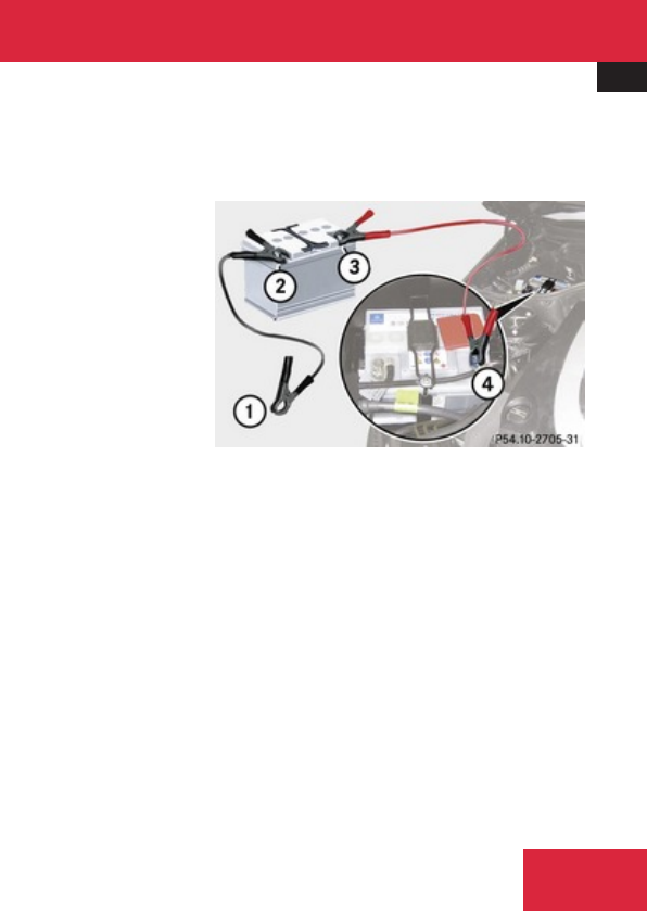
Jump starting
579
! Avoid repeated and lengthy starting
attempts.
Do not attempt to start the engine using a
battery quick-charge unit.
If the engine does not run after several
unsuccessful starting attempts, have it
checked at the nearest authorized
Mercedes-Benz Center.
Excessive unburned fuel generated by
repeated failed starting attempts may
damage the catalytic converter and may
present a fire risk.
Make sure the jumper cables do not have
loose or missing insulation.
Make sure the cable clamps do not touch
any other metal part while the other end is
still attached to a battery.
If the battery is discharged, the engine can be
started with jumper cables and the fully
charged battery of another vehicle or an
equivalent starter pack. Observe the
following:
RAccess to the battery is not possible on all
vehicles. If you cannot access the battery
in your vehicle provide jump start power by
an external battery or starter pack.
RJump starting should only be performed
when the engine and catalytic converter
are cold.
RDo not start the engine if the battery is
frozen. Let the battery thaw out first.
ROnly jump start from batteries with the
same voltage rating (12 V). Jump starting
with a more powerful battery could damage
the vehicle’s electrical system, which will
not be covered by the Mercedes-Benz
Limited Warranty.
ROnly use jumper cables with sufficient
cross-section and insulated terminal
clamps.
RAlways make sure the jumper cables are
not on or near pulleys, fans or other parts
that move when an engine is started or
running.
RShould the battery be drained completely,
let the donating power source charge the
vehicle for several minutes before
reattempting the starting process.
XMake sure the two vehicles do not touch.
XSwitch off all electrical consumers.
XEngage the electronic parking brake.
XMake sure the automatic transmission is in
park position P.
XOpen the hood.
1Negative clamp
2Negative terminal of charged battery
3Positive terminal of charged battery
4Positive terminal of discharged battery
! Never invert the terminal connections!
XConnect positive terminals 3 and 4 of
the batteries with a jumper cable. Clamp
the cable to positive terminal 3 of the
charged battery first.
XConnect negative terminal 2 of charged
battery with a jumper cable and attach
other end of the jumper cable with the
Practical hints
Z

Towing the vehicle
580
negative clamp 1 to a suitable ground
point on the vehicle.
XGet into vehicle and start engine within
30 seconds.
If the starting attempt does not succeed:
XTurn the SmartKey in starter switch to
position 0.
XTake out the SmartKey.
XTurn off engine of donor vehicle, restart it
and let it run at idle speed for several
minutes.
XDisconnect the jumper cable during this
time.
XReconnect jumper cable as described
before.
XRestart engine.
If the starting attempt is succeed:
XWhile the engine is running, switch off
several electrical consumers such as the
blower.
XRemove the jumper cables first from
negative clamp 1 from ground point and
negative terminal 2, then from positive
terminals 4 and 3.
XHave the battery checked at the nearest
authorized Mercedes-Benz Center.
Towing the vehicle
Safety notes
Mercedes-Benz recommends that the vehicle
be transported with all wheels off the ground
using flatbed or appropriate wheel lift/dolly
equipment. This method is preferable to other
types of towing.
! To prevent damage during transport, do
not tie down vehicle by its chassis or
suspension parts.
If circumstances do not permit the
recommended towing methods, the vehicle
may be towed with all wheels on the ground
or front axle raised (except vehicles with
4MATIC) only so far as necessary to have the
vehicle moved to a safe location where the
recommended towing methods can be
employed.
! Before towing the vehicle observe the
following instructions:
RDo not tow-start the vehicle. You could
otherwise seriously damage the
automatic transmission which is not
covered by the Mercedes-Benz Limited
Warranty.
RDo not tow with sling-type equipment.
Towing with sling-type equipment over
bumpy roads will damage radiator and
supports.
RTowing of the vehicle should only be
done using the properly installed towing
eye bolt. Never attach a tow cable, tow
rope or tow rod to the vehicle chassis,
frame or suspension parts.
iIf the battery is disconnected or
discharged
Rthe SmartKey will not turn in the starter
switch
Rthe automatic transmission will remain in
park position P
RFor more information see
“Battery” (Y page 576) or “Jump
starting” (Y page 578).
Practical hints
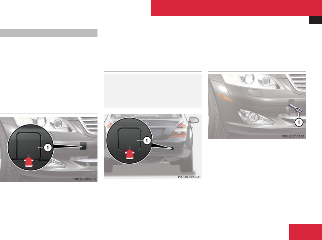
Towing the vehicle
581
Installing towing eye bolt
Depending on whether you are towing a
vehicle or you are being towed, the towing eye
bolt can be screwed into threaded holes
which are located behind covers on each
bumper.
The towing eye bolt is supplied with the
vehicle tool kit, located underneath the trunk
floor (Y page 492).
XTake the vehicle tool kit out of the trunk.
Removing cover in front bumper
1Cover
XPress mark on cover 1 as indicated by the
arrow.
XLift cover 1 off to reveal the threaded hole
for the towing eye bolt.
Removing cover in rear bumper
GWarning!
In order to avoid possible serious burns or
injury, use extreme caution when removing
the rear cover, because the rear exhaust
pipe is extremely hot.
1Cover
XPress mark on cover 1 as indicated by the
arrow.
XLift cover 1 off to reveal the threaded hole
for the towing eye bolt.
Fixing towing eye bolt
Example illustration front bumper
1Towing eye bolt
XTake the towing eye bolt and the wheel
wrench from the vehicle tool kit.
XScrew towing eye bolt 1 clockwise into
threaded hole to its stop.
XInsert wheel wrench into towing eye and
tighten towing eye bolt 1 by turning it
clockwise.
Practical hints
Z

Towing the vehicle
582
Removing towing eye bolt
XLoosen towing eye bolt 1
counterclockwise with wheel wrench.
XUnscrew towing eye bolt 1.
XReinstalling cover: Fit cover 1
(Y page 581) and snap it into place.
XStore the towing eye bolt and wheel wrench
back into the vehicle tool kit.
Towing with all wheels on the ground
GWarning!
If circumstances require towing the vehicle
with all wheels on the ground, always tow
with a tow bar if:
Rthe engine will not run
Rthere is a malfunction in the brake
system
Rthere is a malfunction in the power
supply or in the vehicle’s electrical
system
This is necessary to adequately control the
towed vehicle.
Prior to towing the vehicle with all wheels
on the ground, make sure the SmartKey is
in starter switch position 2.
GWarning!
With the engine not running, there is no
power assistance for the brake and
steering systems. In this case, it is
important to keep in mind that a
considerably higher degree of effort is
necessary to brake and steer the vehicle.
Adapt your driving accordingly.
XMake sure the ignition is switched on.
XWith the vehicle at a standstill, depress the
brake pedal and keep it pressed.
XShift the automatic transmission into
neutral position N.
XRelease the brake pedal.
XIf engaged, release the electronic parking
brake.
XSwitch on the hazard warning flasher
(Y page 328).
! Keep in mind that it is important to have
the ignition switched on. Removing the
SmartKey from the starter switch or
opening a front door with the ignition
switched off will automatically shift the
automatic transmission into park position
P.
! The vehicle may be towed only for
distances up to 30 miles (50 km) and at a
speed not to exceed 30 mph (50 km/h).
iTo signal turns while being towed with the
hazard warning flasher in use you can
activate the combination switch for the left
or right turn signal in the usual manner –
only the selected turn signal will operate.
Upon canceling the turn signal, the hazard
warning flasher will operate again.
Towing with front axle raised
! Vehicles with 4MATIC: Do not tow with
the front axle raised. Doing so could
damage the transfer case, which is not
covered by the Mercedes-Benz Limited
Warranty.
All wheels must be on or off the ground.
Observe instructions for towing the vehicle
with all wheels on the ground.
When towing the vehicle with the front axle
raised, the wheels on the ground have to
move freely.
Practical hints

Fuses
583
XSwitch off the automatic central locking
(Y page 222).
XSwitch on the hazard warning flasher
(Y page 328).
XMake sure the automatic transmission
remains in neutral position N. Observe
instructions, see “Remaining in neutral
position N” (Y page 347).
! Vehicles without 4MATIC:
Because the ESP® operates automatically,
the engine and ignition must be shut off
(SmartKey in starter switch position 0 or
1 or KEYLESS-GO start/stop button in
position 0 or 1) when the vehicle is being
towed with one axle raised.
Active braking action through the ESP®
may otherwise seriously damage the brake
system which is not covered by the
Mercedes-Benz Limited Warranty.
! Keep in mind that it is important for the
SmartKey to be left in starter switch with
the ignition switched off. As soon as the
SmartKey is removed from the starter
switch the automatic transmission will shift
to park position P.
! The vehicle may be towed only for
distances up to 30 miles (50 km) and at a
speed not to exceed 30 mph (50 km/h).
Fuses
Introduction
The electrical fuses in your vehicle serve to
switch off malfunctioning power circuits.
If a fuse is blown, the components and
systems secured by that fuse will stop
operating.
GWarning!
Only use fuses approved by Mercedes-Benz
with the specified amperage for the system
in question and do not attempt to repair or
bridge a blown fuse. Using other than
approved fuses or using repaired or bridged
fuses may cause an overload leading to a
fire, and/or cause damage to electrical
components and/or systems. Have the
cause determined and remedied by an
authorized Mercedes-Benz Center.
! Switch off the vehicle’s internal electrical
functions when you are working on the
fuses.
A blown fuse must be replaced by an
appropriate spare fuse (recognizable by its
color or the fuse rating given on the fuse) of
the amperage recommended in the fuse
chart. Any Mercedes-Benz Center will be glad
to advise you on this subject.
Practical hints
Z
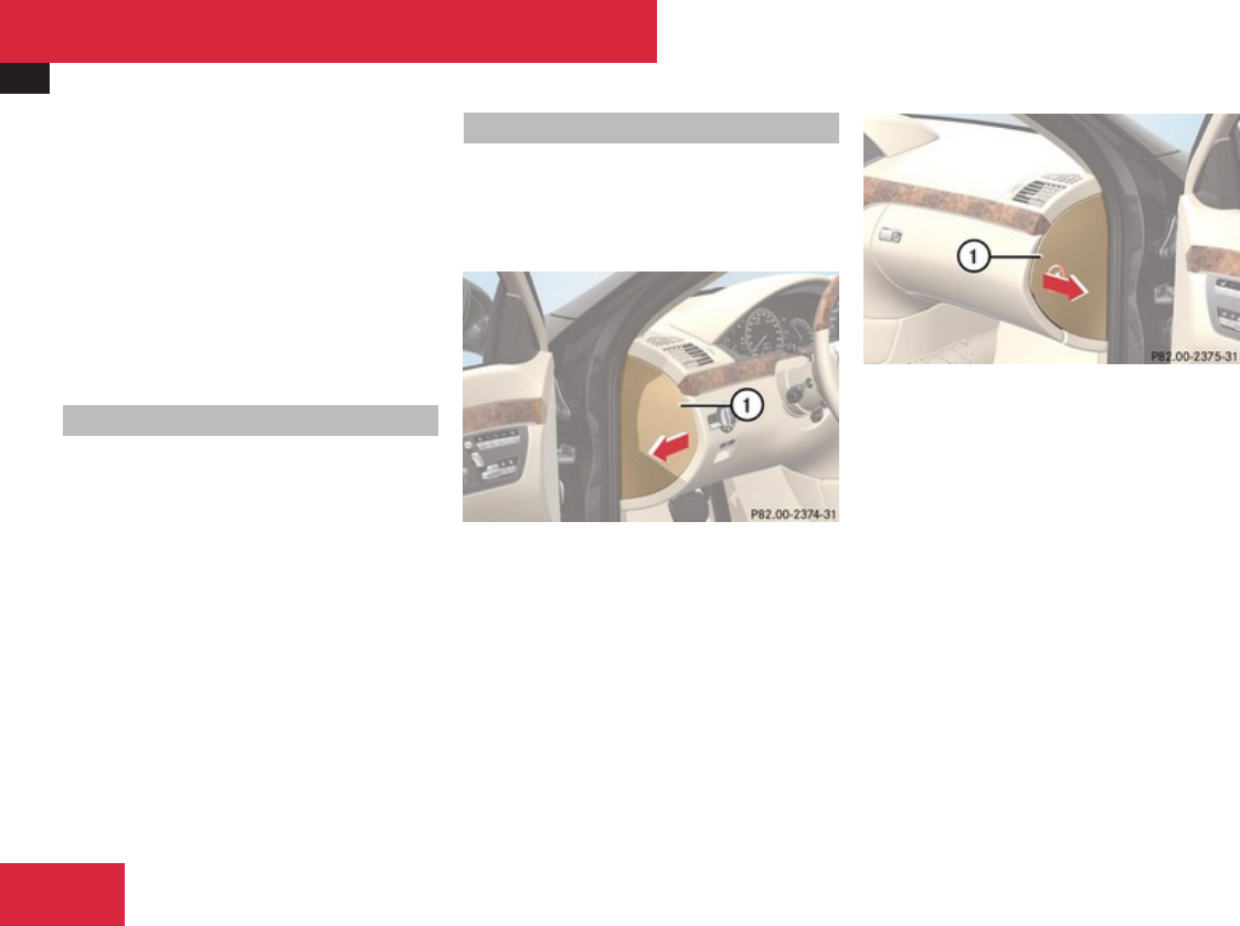
Fuses
584
iIn case of a blown fuse contact Roadside
Assistance or an authorized Mercedes-
Benz Center.
If a newly inserted fuse blows again, have the
cause determined and rectified by an
authorized Mercedes-Benz Center.
A fuse chart is located in the trunk with the
vehicle tool kit (Y page 492). The fuse chart
explains the fuse allocation and fuse
amperages.
Before replacing fuses
XEngage the electronic parking brake.
XMake sure the automatic transmission is in
park position P.
The transmission position indicator in the
multifunction display should be on P.
XSwitch off all electrical consumers.
XTurn off the engine.
Fuse box in passenger compartment
! Do not use sharp objects such as a
screwdriver to open the fuse box cover in
the dashboard. You could damage the fuse
box cover or the dashboard.
Fuse box on driver’s side
1Fuse box cover
Fuse box on passenger side
1Fuse box cover
XOpen the respective door.
XUsing your hands, pull cover 1 in direction
of arrow and remove it.
XClosing: Hook cover 1 into the opening at
the front.
! The fuse box cover must be properly
positioned as described to prevent
moisture or dirt from entering the fuse box
and possibly impairing fuse operation.
Practical hints
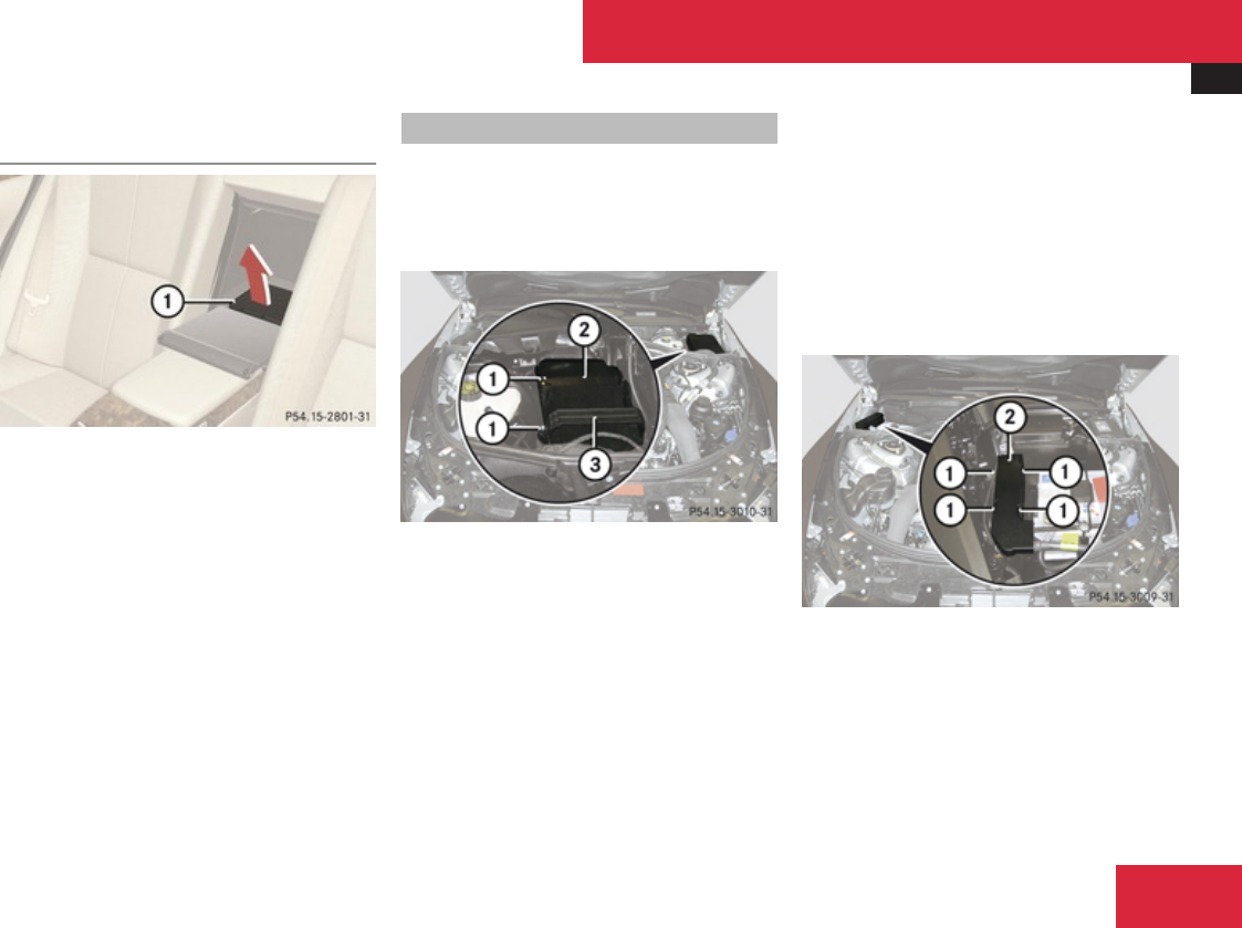
Fuses
585
Fuse box in the rear passenger
compartment
1Cover
XOpening: Swing down center armrest.
XOpen cover behind center armrest.
XPull cover 1 forward in direction of arrow.
XClosing: Press cover 1 backward and
engage.
! Make sure the seal in the cover is not
damaged during opening or closing.
Fuse box in engine compartment
The fuse boxes are located in the engine
compartment on the driver’s and passenger
side.
XOpen the hood.
Fuse box on driver’s side
14 screws
2Fuse box cover
3Bracket
XS 63 AMG: Remove the control box above
the fuse box.
XRemoving cover: Take the crank from the
Operator’s Manual pouch.
XLoosen screws 1 with crank.
XRemove bracket 3.
XRemove fuse box cover 2.
XInstalling cover: Attach fuse box cover
2.
XAttach bracket 3.
XTighten screws 1 with crank.
! The fuse box cover must be installed
properly to prevent moisture and/or dirt
from entering the fuse box and possibly
impairing fuse operation.
Example illustration fuse box on passenger side
1Retaining lugs
2Fuse box cover
XRemoving cover: Press retaining lugs 1.
XRemove fuse box cover 2.
XInstalling cover: Attach fuse box cover
2.
XPress fuse box cover 2 down.
Practical hints
Z

Fuses
586
! The fuse box cover must be installed
properly to prevent moisture and/or dirt
from entering the fuse box and possibly
impairing fuse operation.
XClose the hood after checking or replacing
fuses.
Emergency engine shutdown
If the engine cannot be turned off as
described (Y page 344), you may use the
following emergency procedure.
XTake the fuse chart from the vehicle tool kit
(Y page 492).
XFind row “Emergency engine shutdown” in
the fuse chart table to identify the fuses
that have to removed as well as their
locations.
XRemove the respective fuses.
Practical hints

587
Vehicle equipment ............................ 588
Parts service ..................................... 588
Warranty coverage ........................... 588
Identification labels .......................... 589
Engine ................................................ 591
Rims and tires ................................... 594
Electrical system .............................. 600
Main dimensions ............................... 601
Weights .............................................. 602
Fuels, coolants, lubricants etc. ....... 603
Technical data

Warranty coverage
588
Vehicle equipment
iThis Operator’s Manual describes all
features, standard or optional, potentially
available for your vehicle at the time of
purchase. Please be aware that your
vehicle might not be equipped with all
features described in this manual.
Parts service
All authorized Mercedes-Benz Centers
maintain a stock of Genuine Mercedes-Benz
Parts required for maintenance and repair
work. In addition, strategically located parts
distribution centers provide quick and
reliable parts service.
More than 300 000 different parts for
Mercedes-Benz models are available.
Genuine Mercedes-Benz Parts are subjected
to stringent quality inspections. Each part has
been specifically developed, manufactured or
selected for and adapted to Mercedes-Benz
vehicles.
Therefore, Genuine Mercedes-Benz Parts
should be installed.
! Do not use non-genuine Mercedes-Benz
parts and accessories not authorized by
Mercedes-Benz. Doing so could damage
the vehicle, which is not covered by the
Mercedes-Benz Limited Warranty. Also, it
could compromise the vehicle’s durability
or safety.
Warranty coverage
Your vehicle is covered under the terms of the
warranties printed in the Service and
Warranty Information booklet.
Your authorized Mercedes-Benz Center will
exchange or repair any defective parts
originally installed in the vehicle in
accordance with the terms of the following
warranties:
RNew Car Limited Warranty
REmission System Warranty
REmission Performance Warranty
RCalifornia, Connecticut, Maine,
Massachusetts, New York, Pennsylvania,
Rhode Island, and Vermont Emission
Control Systems Warranty
RState Warranty Enforcement Laws (Lemon
Laws)
Replacement parts and accessories are
covered by the Mercedes-Benz Parts and
Accessories warranties, copies of which are
available at any authorized Mercedes-Benz
Center.
Technical data
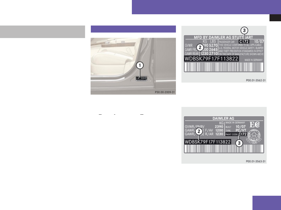
Identification labels
589
Loss of Service and Warranty
Information booklet
Should you lose your Service and Warranty
Information booklet, have an authorized
Mercedes-Benz Center arrange for a
replacement. It will be mailed to you.
Identification labels
1Certification label (on driver’s door
B-pillar)
The Vehicle Identification Number (VIN) can
be found in the following locations:
Ron the certification label
Rembossed underneath a cover behind the
rear center armrest (Y page 590)
Ron the lower edge of the windshield
(Y page 590)
Example certification label (U.S. vehicles)
2VIN
3Paintwork code
Example certification label (Canada vehicles)
2VIN
3Paintwork code
Technical data
Z
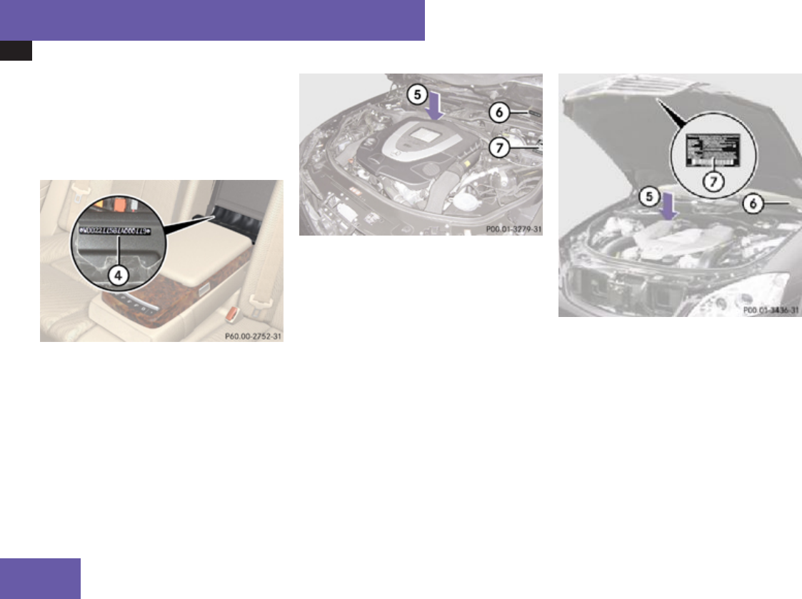
Identification labels
590
iData shown on certification label are for
illustration purposes only. These data are
specific to each vehicle and may vary from
data shown in the illustration. Refer to
certification label on vehicle for actual data
specific to your vehicle.
Rear center armrest
4VIN
XFold down the rear center armrest.
The VIN is embossed underneath a cover
behind the rear center armrest.
XOpen the cover.
VIN 4 is now visible.
All models except AMG vehicles
5Engine number (engraved on engine)
6VIN (on lower edge of windshield)
7Emission control information label,
includes both federal and California
certification exhaust emission standards AMG vehicles
5Engine number (engraved on engine)
6VIN (on lower edge of windshield)
7Emission control information label,
includes both federal and California
certification exhaust emission standards
iWhen ordering parts, please specify
vehicle identification and engine number.
Technical data

Engine
591
Engine
Model S 450 4MATIC (221.084)11,12 S 550 (221.171)11,13 S 550 4MATIC (221.186)11
Engine 273 273 273
Mode of operation 4-stroke engine, gasoline injection 4-stroke engine, gasoline injection 4-stroke engine, gasoline injection
No. of cylinders 8 8 8
Bore 3.66 in (92.90 mm) 3.86 in (98.00 mm) 3.86 in (98.00 mm)
Stroke 3.39 in (86.00 mm) 3.56 in (90.50 mm) 3.56 in (90.50 mm)
Total piston
displacement
284.6 cu in (4 663 cm3) 333.3 cu in (5 461 cm3) 333.3 cu in (5 461 cm3)
Compression ratio 10.5:1 10.7:1 10.5:1
Output acc. to
SAE J 1349
335 hp/6 000 rpm
(250 kW/6 000 rpm)14
382 hp/6 000 rpm
(285 kW/6 000 rpm)14
382 hp/6 000 rpm
(285 kW/6 000 rpm)14
Maximum torque acc. to
SAE J 1349
339 lb-ft/2 700 rpm - 5 000 rpm
(460 Nm/2 700 rpm - 5 000 rpm)
391 lb-ft/3 000 rpm
(530 Nm/3 000 rpm)
391 lb-ft/2 800 rpm - 4 800 rpm
(530 Nm/2 800 rpm - 4 800 rpm)
Maximum engine speed 6 500 rpm 6 500 rpm 6 500 rpm
11 The quoted data apply only to the standard vehicle. Contact an authorized Mercedes-Benz Center for the corresponding data of all special bodies and special equipment.
12 Canada only.
13 USA only.
14 Premium fuel required. Performance may vary with fuel octane rating.
Technical data
Z

Engine
592
Model S 450 4MATIC (221.084)11,12 S 550 (221.171)11,13 S 550 4MATIC (221.186)11
Firing order 1-5-4-2-6-3-7-8 1-5-4-2-6-3-7-8 1-5-4-2-6-3-7-8
Poly-V-belt 2 404 mm 2 404 mm 2 404 mm
Technical data

Engine
593
Model S 600 (221.176)15 S 63 AMG (221.177)15 S 65 AMG (221.179)15
Engine 275 156 275
Mode of operation 4-stroke engine, gasoline injection 4-stroke engine, gasoline injection 4-stroke engine, gasoline injection
No. of cylinders 12 8 12
Bore 3.23 in (82.00 mm) 4.02 in (102.20 mm) 3.25 in (82.60 mm)
Stroke 3.43 in (87.00 mm) 3.72 in (94.60 mm) 3.66 in (93.00 mm)
Total piston
displacement
336.4 cu in (5 513 cm3) 378.8 cu in (6 208 cm3) 364.9 cu in (5 980 cm3)
Compression ratio 9:1 11.3:1 9:1
Output acc. to
SAE J 1349
510 hp/5 000 rpm
(380 kW/5 000 rpm)16
518 hp/6 800 rpm
(386 kW/6 800 rpm)16
603 hp/4 800 - 5 100 rpm
(450 kW/4 800 - 5 100 rpm)16
Maximum torque acc. to
SAE J 1349
612 lb-ft/1 800 rpm - 3 500 rpm
(830 Nm/1 800 rpm - 3 500 rpm)
465 lb-ft/5 200 rpm
(630 Nm/5 200 rpm)
738 lb-ft/2 000 rpm - 4 000 rpm
(1 000 Nm/2 000 rpm - 4 000 rpm)
Maximum engine speed 5 950 rpm 7 200 rpm 5 950 rpm
Firing order 1-12-5-8-3-10-6-7-2-11-4-9 1-5-4-2-6-3-7-8 1-12-5-8-3-10-6-7-2-11-4-9
Poly-V-belt 2 370 mm 2 360 mm 2 370 mm
15 The quoted data apply only to the standard vehicle. Contact an authorized Mercedes-Benz Center for the corresponding data of all special bodies and special equipment.
16 Premium fuel required. Performance may vary with fuel octane rating.
Technical data
Z

Rims and tires
594
Rims and tires
Notes
! Only use tires which have been tested and
approved by Mercedes-Benz. Tires
approved by Mercedes-Benz are developed
to provide best possible performance in
conjunction with the driving safety systems
on your vehicle such as the ABS or the
ESP®. Tires specially developed for your
vehicle and tested and approved by
Mercedes-Benz can be identified by finding
the following on the tire’s sidewall:
RMO = Mercedes-Benz Original
equipment tires
Using tires other than those approved by
Mercedes-Benz may result in damage that
is not covered by the Mercedes-Benz
Limited Warranty.
! Using tires other than those approved by
Mercedes-Benz can have detrimental
effects, such as
Rpoor handling characteristics
Rincreased noise
Rincreased fuel consumption
Moreover, tires and rims not approved by
Mercedes-Benz may, under load, exhibit
dimensional variations and different tire
deformation characteristics that could
cause them to come into contact with the
vehicle body or axle parts. Damage to the
tires or the vehicle may be the result.
iFurther information on tires and rims is
available at any authorized Mercedes-Benz
Center. A placard with the recommended
tire inflation pressures is located on the
driver’s door B-pillar. Some vehicles may
have supplemental tire inflation pressure
information for driving at high speeds or for
vehicle loads less than the maximum
loaded vehicle condition. If such
information is provided, it can be found on
the placard located on the inside of the fuel
filler flap. The tire inflation pressure should
be checked regularly and should only be
adjusted on cold tires. Follow tire
manufacturer’s maintenance
recommendation included with the vehicle.
For information on recommended tire
inflation pressure and supplemental tire
inflation pressure information for special
driving situations, see (Y page 456).
iThe following pages also list the approved
wheel rim and tire sizes for equipping your
vehicles with winter tires. Winter tires are
not available as standard or optional
factory equipment, but can be purchased
from an authorized Mercedes-Benz Center.
Equipping your vehicle with winter tires
approved for your vehicle model may
require the purchase of two or four wheel
rims of the recommended size for use with
these winter tires. This depends on vehicle
model and the standard or optional factory-
equipped wheel rim/tire configuration on
your vehicle. For more information contact
an authorized Mercedes-Benz Center.
Technical data

Rims and tires
595
Same size tires
Model S 450 4MATIC17
S 55018
S 550 4MATIC
S 550 4MATIC S 450 4MATIC (AMG Sport Package)17
S 550 4MATIC (AMG Sport Package)
Rims (light alloy) 8.5 J x 18 H2 8.5 J x 19 H2 —
AMG rims (light alloy) — — 8.5 J x 19 H2
Wheel offset 1.69 in (43 mm) 1.69 in (43 mm) 1.69 in (43 mm)
All-season tires19 255/45 R18 99H M+S 255/40 R19 100Y XL (Extra Load)
M+S
255/40 R19 100V XL (Extra Load) M+S
Winter tires19,20,21 255/45 R18 99V M+S.— 255/40 R19 100V XL (Extra Load)
M+S.
17 Canada only.
18 USA only.
19 Radial-ply tires.
20 For use with snow chains contact an authorized Mercedes-Benz Center.
21 Not available as factory equipment.
Technical data
Z

Rims and tires
596
Model S 600
S 550 (Sport Package)
S 600 (Sport Package)
S 63 AMG
S 63 AMG (Performance Package)
S 65 AMG
S 550 4MATIC
Rims (light alloy) 8.5 J x 18 H2 — —
AMG rims (light alloy) — 8.5 J x 19 H2 8.5 J x 20 H2
Wheel offset 1.69 in (43 mm) 1.69 in (43 mm) 1.69 in (43 mm)
Summer tires22,23 — — 255/35 ZR20 XL (Extra Load)
Winter tires22,24,25 255/45 R18 99V M+S.255/40 R19 100V XL (Extra Load)
M+S.
—
22 Radial-ply tires.
23 Must not be used with snow chains.
24 For use with snow chains contact an authorized Mercedes-Benz Center.
25 Not available as factory equipment.
Technical data

Rims and tires
597
Mixed size tires
Model S 60026 S 55026
S 600
Front axle Rims (light alloy) 8.5 J x 18 H2 8.5 J x 19 H2
Wheel offset 1.69 in (43 mm) 1.69 in (43 mm)
All-season tires27 255/45 R18 99H M+S 255/40 R19 100V XL (Extra Load)
M+S
Rear axle Rims (light alloy) 9.5 J x 18 H2 9.5 J x 19 H2
Wheel offset 1.69 in (43 mm) 1.69 in (43 mm)
All-season tires27 275/45 R18 103H M+S 275/40 R19 101V M+S
26 USA only.
27 Radial-ply tires.
Technical data
Z

Rims and tires
598
Model S 550 (AMG Sport Package)28 S 550
S 63 AMG
S 63 AMG (Performance Package)
S 65 AMG
Front axle AMG rims (light alloy) 8.5 J x 19 H2 8.5 J x 20 H2
Wheel offset 1.69 in (43 mm) 1.69 in (43 mm)
Summer tires29 255/40 R19 100Y XL (Extra Load) 255/35 ZR20 XL (Extra Load)
Rear axle AMG rims (light alloy) 9.5 J x 19 H2 9.5 J x 20 H2
Wheel offset 1.69 in (43 mm) 1.69 in (43 mm)
Summer tires29,30 275/40 R19 101Y 275/35 ZR20 XL (Extra Load)
28 USA only.
29 Radial-ply tires.
30 Must not be used with snow chains.
Technical data

Rims and tires
599
Spare wheel
! Compare the recommended tire inflation pressure for your vehicle with the tire inflation pressure on the yellow label located on the spare
wheel rim.
If the tire inflation pressure on the yellow label on the spare wheel rim differs from the values given in this Operator’s Manual, inflate the
tire to the recommended tire inflation pressure given on the yellow label on the spare wheel rim.
iPlease note that the tire inflation pressure of the spare wheel differs from the tire inflation pressure of the road tires.
Model All models
(except AMG vehicles)
S 63 AMG
S 63 AMG (Performance Package)
S 65 AMG
Rim (steel) 4.5 B x 19 H2 —
Rim (light alloy) — 4.5 B x 19 H2
Wheel offset 1.38 in (35 mm) 1.38 in (35 mm)
Minispare tire31 T 155/70 R19 113M T 155/70 R19 113M
Recommended tire inflation pressure 61 psi (4.2 bar) 61 psi (4.2 bar)
31 Must not be used with snow chains.
Technical data
Z

Electrical system
600
Electrical system
Model S 450 4MATIC32
S 55033
S 550 4MATIC
S 600 S 63 AMG S 65 AMG
Alternator 14 V/180 A 14 V/220 A 14 V/220 A 14 V/220 A
Starter motor 12 V/1.7 kW 12 V/2.0 kW 12 V/2.1 kW 12 V/1.7 kW
Starter
battery
12 V/35 Ah 12 V/35 Ah 12 V/35 Ah 12 V/35 Ah
Battery for
electrical
consumers
12 V/95 Ah 12 V/95 Ah 12 V/95 Ah 12 V/95 Ah
Spark plugs Type NGK PLKR 6A
Bosch Y 7 MPP33
NGK IFR 6Q-G NGK ILZKAR 7A10 NGK IFR 6Q-G
Electrode gap 0.031 in (0.8 mm) 0.028 in (0.7 mm) 0.039 in (1.0 mm) 0.028 in (0.7 mm)
Tightening
torque
15 lb-ft - 18 lb-ft
(20 Nm - 25 Nm)
15 lb-ft - 22 lb-ft
(20 Nm - 30 Nm)
15 lb-ft - 18 lb-ft
(20 Nm - 25 Nm)
15 lb-ft - 22 lb-ft
(20 Nm - 30 Nm)
32 Canada only.
33 USA only.
Technical data

Main dimensions
601
Main dimensions
Model S 450 4MATIC34
S 550 4MATIC
S 55035
S 600
S 63 AMG
S 65 AMG
Overall vehicle length 205.1 in (5 210 mm) 205.1 in (5 210 mm) 206.5 in (5 245 mm)
Overall vehicle width, exterior rear view mirrors folded out 83.2 in (2 113 mm) 83.2 in (2 113 mm) 83.2 in (2 113 mm)
Overall vehicle height 58.9 in (1 495 mm) 58.5 in (1 485 mm) 58.0 in (1 473 mm)
Wheelbase 124.6 in (3 165 mm) 124.6 in (3 165 mm) 124.6 in (3 165 mm)
Track, front 63.2 in (1 604 mm) 63.2 in (1 604 mm) 63.2 in (1 604 mm)
Track, rear 63.2 in (1 606 mm) 63.2 in (1 606 mm) 63.2 in (1 606 mm)
Turning circle 40.0 ft (12.2 m) 40.0 ft (12.2 m) 40.0 ft (12.2 m)
34 Canada only.
35 USA only.
Technical data
Z


Fuels, coolants, lubricants etc.
603
Fuels, coolants, lubricants etc.
Capacities
Vehicle components and their respective
lubricants must match. Therefore only use
products tested and approved by Mercedes-
Benz.
For information on tested and approved
products, contact an authorized Mercedes-
Benz Center or visit www.mbusa.com (USA
only).
GWarning!
Comply with all valid regulations with
respect to handling, storing, and disposing
of service fluids. Otherwise you could
endanger persons or the environment.
Keep service fluids out of the reach of
children.
For health reasons, you should prevent
service fluids from coming into direct
contact with your skin or clothing.
If a service fluid is swallowed, contact a
physician immediately.
Model Capacity Fuels, coolants, lubricants, etc.
Engine with oil filter S 450 4MATIC36
S 55037
S 550 4MATIC
9.0 US qt (8.5 l) Approved engine oils
S 600
S 65 AMG
9.5 US qt (9.0 l)
S 63 AMG38 9.9 US qt (9.35 l)
Automatic transmission S 450 4MATIC36
S 550 4MATIC
10.1 US qt (9.6 l) MB Automatic Transmission Fluid
36 Canada only.
37 USA only.
38 Engine with oil cooler.
Technical data
Z

Fuels, coolants, lubricants etc.
604
Model Capacity Fuels, coolants, lubricants, etc.
S 55037 10.4 US qt (9.8 l)
S 600 8.1 US qt (7.7 l)
S 63 AMG39 9.25 US qt (8.75 l)
S 65 AMG 9.2 US qt (8.7 l)
Rear axle S 450 4MATIC36
S 550 4MATIC
1.9 US qt (1.8 l) Hypoid gear oil SAE 85 W 90
S 55037 1.3 US qt (1.2 l)
S 600 2.1 US qt (2.0 l)
S 63 AMG 1.3 US qt (1.2 l) Fuchs Titan EG 5010 D
S 65 AMG 1.7 US qt (1.6 l)
Hydraulic system for active body
control (ABC)
All models except 4MATIC 4.2 US qt (4.0 l) MB ABC Fluid
37 USA only.
39 Automatic transmission with oil cooler.
36 Canada only.
Technical data

Fuels, coolants, lubricants etc.
605
Model Capacity Fuels, coolants, lubricants, etc.
Power steering S 450 4MATIC36
S 55037
S 550 4MATIC
S 63 AMG
1.1 US qt (1.0 l) MB Power Steering Fluid
(Chevron Texaco PSF 9109)
S 600
S 65 AMG
1.3 US qt (1.2 l)
Brake system 0.63 US qt (0.6 l) MB Brake Fluid (DOT 4+)
Cooling system (vehicles without
rear climate control)
S 450 4MATIC36 approx. 15.6 US qt (14.8 l) MB 325.0 Anticorrosion/Antifreeze
S 55037
S 550 4MATIC
approx. 12.2 US qt (11.5 l)
Cooling system (vehicles with
rear climate control)
S 450 4MATIC36 approx. 17.1 US qt (16.2 l) MB 325.0 Anticorrosion/Antifreeze
S 55037
S 550 4MATIC
approx. 13.8 US qt (13.1 l)
S 600
S 65 AMG
approx. 14.7 US qt (13.9 l)
S 63 AMG approx. 11.8 US qt (11.2 l)
Low temperature cooling system S 600 approx. 2.8 US qt (2.6 l) MB 325.0 Anticorrosion/Antifreeze
S 65 AMG approx. 3.3 US qt (3.1 l)
36 Canada only.
37 USA only.
Technical data
Z

Fuels, coolants, lubricants etc.
606
Model Capacity Fuels, coolants, lubricants, etc.
Fuel tank,
including a reserve of
23.8 US gal (90.0 l) Premium unleaded gasoline
(Minimum Posted Octane 91
[Avg. of 96 RON/86 MON])
All models except AMG vehicles 2.9 US gal (11.0 l)
AMG vehicles 3.7 US gal (14.0 l)
Air conditioning system — R134a refrigerant and special
PAG lubricant oil (never R 12)
Washer system and headlamp
cleaning system
6.9 US qt (6.5 l) MB Windshield Washer
Concentrate40 (Y page 612)
Washer fluid mixing ratio
(Y page 612)
Approved engine oils
Engine oils are specifically tested for their
suitability in our engines and durability for our
service intervals. Therefore, only use
approved engine oils and oil filters required
for vehicles with Maintenance System.
For a listing of approved engine oils and oil
filters, contact an authorized Mercedes-Benz
Center or visit www.mbusa.com (USA only).
! Using engine oils and oil filters of a
specification other than those expressly
required for the Maintenance System, or
changing of oil and oil filter at change
intervals longer than those called for by the
Maintenance System will result in engine or
emission control system damage not
covered by the Mercedes-Benz Limited
Warranty.
Please follow Maintenance System
recommendations for scheduled oil
changes. Failure to do so will result in
engine or emission control system damage
not covered by the Mercedes-Benz Limited
Warranty.
Mercedes-Benz recommends MOBIL OIL.
40 Mixed with water or commercially available premixed washer solvent/antifreeze.
Technical data
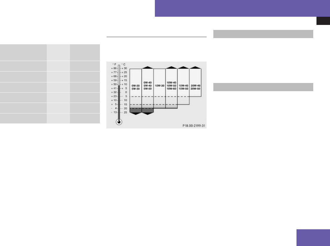
Fuels, coolants, lubricants etc.
607
Use the table below to determine the
MB sheet number.
Model Engine
type
MB sheet
number
S 450 4MATIC41 273 229.5
S 55042 273 229.5
S 550 4MATIC 273 229.5
S 600 275 229.5
S 63 AMG 156 229.543
S 65 AMG 275 229.5
iMB sheet numbers are printed on the
outside of oil containers.
Viscosity grades for engine oils
Using the chart below, select oil viscosity
according to the lowest air temperature
expected before the next oil change.
Engine oil additives
! Do not blend oil additives with engine oil.
They may damage the engine. Damage or
malfunctions resulting from blending oil
additives are not covered by the Mercedes-
Benz Limited Warranty.
Air conditioning refrigerant
R134a (HFC) refrigerant and special PAG
lubricating oil are used in the air conditioning
system.
! Never use R 12 (CFC) or mineral-based
lubricating oil. Otherwise damage to the
system will occur.
41 Canada only.
42 USA only.
43 Restriction: Only SAE 0W-40/SAE 5W-40 engine oils may be used.
Technical data
Z

Fuels, coolants, lubricants etc.
608
Brake fluid
GWarning!
During vehicle operation, the boiling point
of the brake fluid is continuously reduced
through the absorption of moisture from
the atmosphere.
Under extremely strenuous operating
conditions, this moisture content can lead
to the formation of bubbles in the system,
thus reducing the system’s efficiency.
Therefore, the brake fluid must be replaced
regularly. Refer to your vehicle’s
Maintenance Booklet for replacement
interval.
Only brake fluid approved by Mercedes-Benz
is recommended. Any authorized Mercedes-
Benz Center will provide you with additional
information.
Premium unleaded gasoline
GWarning!
Gasoline is highly flammable and
poisonous. It burns violently and can cause
serious personal injury.
Never allow sparks, flames or smoking
materials near gasoline!
Turn off the engine before refueling.
Whenever you are around gasoline, avoid
inhaling fumes and any skin or clothing
contact. Extinguish all smoking materials.
Direct skin contact with fuels and the
inhalation of fuel vapors are damaging your
health.
! To maintain the engine’s durability and
performance, premium unleaded gasoline
must be used.
If premium unleaded gasoline is not
available and low octane gasoline is used,
follow these precautions:
RHave the fuel tank only partially filled
with unleaded regular gasoline and fill up
with premium unleaded gasoline as soon
as possible.
RAvoid full throttle driving and abrupt
acceleration.
RDo not exceed an engine speed of
3 000 rpm if the vehicle is loaded with a
light load such as two persons and no
luggage.
RDo not exceed 2/3 of maximum
accelerator pedal position if the vehicle
is fully loaded or operating in
mountainous terrain.
Fuel requirements
Only use premium unleaded gasoline. The
octane number (posted at the pump) must be
91 min. It is an average of both the Research
Octane Number (RON) and the Motor Octane
Number (MON): (RON+MON)/2. This is also
known as the ANTI-KNOCK INDEX.
Reformulated gasolines (RFG) and/or
unleaded gasoline containing oxygenates
such as ethanol, TAME, ETBE, IPA, IBA, and
TBA can be used provided the ratio of any one
of these oxygenates to gasoline does not
exceed 10%; MTBE must not exceed 15%.
The ratio of methanol to gasoline must not
exceed 3% plus additional cosolvents.
Using mixtures of ethanol and methanol is not
allowed. Gasohol, which contains 10%
ethanol and 90% unleaded gasoline, can be
used.
Technical data

Fuels, coolants, lubricants etc.
609
These blends must also meet all other fuel
requirements, such as resistance to spark
knock, boiling range, vapor pressure, etc.
Gasoline additives
A major concern among engine
manufacturers is carbon build-up caused by
gasoline. Mercedes-Benz recommends only
the use of quality gasoline containing
additives that prevent the build-up of carbon
deposits.
After an extended period of using fuels
without such additives carbon deposits can
build up, especially on the intake valves and
in the combustion area, leading to engine
performance problems such as:
RWarm-up hesitation
RUnstable idle
RKnocking/pinging
RMisfire
RPower loss
In areas where carbon deposits may be
encountered due to lack of availability of
gasoline which contains these additives,
Mercedes-Benz recommends the use of
additives approved by us for use on
Mercedes-Benz vehicles.
Contact an authorized Mercedes-Benz Center
or visit www.mbusa.com (USA only) for a
listing of approved product(s). Follow
directions on product label.
Do not blend other fuel additives with fuel.
This only results in unnecessary cost and may
be harmful to the engine operation.
! Damage or malfunction resulting from
poor fuel quality or from blending additional
fuel additives other than those tested and
approved by us for use on Mercedes-Benz
vehicles are not covered by the Mercedes-
Benz Limited Warranty or by any pre-owned
or Extended Limited warranties.
Coolants
The engine coolant is a mixture of water and
anticorrosion/antifreeze, which provides:
RCorrosion protection
RFreeze protection
RBoiling protection (by increasing the boiling
point)
The cooling system was filled at the factory
with a coolant providing freeze protection to
approximately -35‡ (-37†) and corrosion
protection.
! Add premixed coolant solution only.
Adding water and MB 325.0 Anticorrosion/
Antifreeze separately from each other,
could cause engine damage not covered by
the Mercedes-Benz Limited Warranty.
If the antifreeze mixture is effective to -35‡
(-37†), the boiling point of the coolant in the
pressurized cooling system is reached at
approximately 266‡ (130†).
The coolant solution must be used year round
to provide the necessary corrosion protection
and increase boil-over protection. Refer to
the Maintenance Booklet for replacement
interval.
Coolant system design and coolant used
determine the replacement interval. The
replacement interval published in the
Maintenance Booklet is only applicable if
MB 325.0 Anticorrosion/Antifreeze solution
or other Mercedes-Benz approved products
of equal specification are used to renew the
coolant concentration or bring it back up to
the proper level.
For information on other Mercedes-Benz
approved products of equal specification,
contact an authorized Mercedes-Benz Center
or visit www.mbusa.com (USA only).
To provide important corrosion protection,
the solution must be at least 50%
Technical data
Z

Fuels, coolants, lubricants etc.
610
anticorrosion/antifreeze (equivalent to
freeze protection to approximately -35‡
[-37†]).
If you use a solution that is more than 55%
anticorrosion/antifreeze (freeze protection
to approximately -49‡ [-45†]), the engine
temperature will increase due to the lower
heat transfer capability of the solution.
Therefore, do not use more than this amount
of anticorrosion/antifreeze.
If the coolant level is low, water and MB 325.0
Anticorrosion/Antifreeze should be used to
bring it up to the proper level (have cooling
system checked for signs of leakage). Please
make sure the mixture is in accordance with
label instructions.
The water in the cooling system must meet
minimum requirements, which are usually
satisfied by normal drinking water.
If you are not sure about the water quality,
contact an authorized Mercedes-Benz
Center.
Anticorrosion/antifreeze
Your vehicle contains a number of aluminum
parts. The use of aluminum components in
motor vehicle engines necessitates that
anticorrosion/antifreeze coolant used in
such engines be specifically formulated to
protect the aluminum parts. Failure to use
such anticorrosion/antifreeze coolant will
result in a significantly shortened service life.
Therefore, the following product is strongly
recommended for use in your vehicle:
MB 325.0 Anticorrosion/Antifreeze agent.
Before the start of the winter season (or once
a year in hot southern regions), you should
have the anticorrosion/antifreeze
concentration checked.
The coolant is also regularly checked each
time you bring your vehicle to an authorized
Mercedes-Benz Center for service.
Technical data

Fuels, coolants, lubricants etc.
611
Model Approximate freeze protection
-35‡ (-37†) -49‡ (-45†)
Cooling system
(vehicles without rear passenger
compartment climate control)
S 450 4MATIC44 7.8 US qt (7.4 l) 8.6 US qt (8.1 l)
S 55045
S 550 4MATIC
6.1 US qt (5.75 l) 6.7 US qt (6.3 l)
Cooling system
(vehicles with rear passenger compartment
climate control)
S 450 4MATIC44 8.6 US qt (8.1 l) 9.4 US qt (8.9 l)
S 55045
S 550 4MATIC
6.9 US qt (6.55 l) 7.6 US qt (7.2 l)
S 600 7.3 US qt (6.95 l) 8.1 US qt (7.65 l)
S 63 AMG 6.0 US qt (5.6 l) 7.0 US qt (6.2 l)
S 65 AMG 7.4 US qt (7.0 l) 8.1 US qt (7.7 l)
Low temperature cooling system S 600 1.4 US qt (1.3 l) 1.5 US qt (1.4 l)
S 65 AMG 1.6 US qt (1.55 l) 1.8 US qt (1.7 l)
44 Canada only.
45 USA only.
Technical data
Z

Fuels, coolants, lubricants etc.
612
Washer system and headlamp
cleaning system
GWarning!
Washer solvent/antifreeze is highly
flammable. Do not spill washer solvent/
antifreeze on hot engine parts, because it
may ignite and burn. You could be seriously
burned.
XUse MB Windshield Washer Concentrate
“MB SummerFit”.
XMix with water for temperatures above
freezing point.
XMix with commercially available premixed
washer solvent/antifreeze for
temperatures below freezing point.
Washer fluid mixing ratio
For temperatures above freezing point:
1 part “MB SummerFit” to 100 parts water
(1.34 fl oz [40 ml] “MB SummerFit” to 1 gal
[4.0 l] water)
For temperatures below freezing point:
1 part “MB SummerFit” to 100 parts solvent
(1.34 fl oz [40 ml] “MB SummerFit” to 1 gal
[4.0 l] solvent)
Technical data

Service and Literature
Your authorized Mercedes-Benz Center has
trained technicians and Genuine Mercedes-
Benz Parts to service your vehicle properly.
For expert advice and quality service, contact
an authorized Mercedes-Benz Center.
If you are interested in obtaining service
literature for your vehicle, please contact an
authorized Mercedes-Benz Center.
We consider this the best way for you to
obtain accurate information for your vehicle.
For further information you can find us on the
Mercedes-Benz web-site www.mbusa.com
(USA only) or www.mercedes-benz.ca
(Canada only).
GWarning!
To help avoid personal injury, be extremely
careful when performing any service work
or repairs. Improper or incomplete service
or the use of incorrect or inappropriate
parts or materials may damage the vehicle
or its equipment, which may in turn result
in personal injury.
If you have any questions about carrying
out any type of service, turn to the advice
of an authorized Mercedes-Benz Center.
We reserve the right to make changes in
design and equipment.
Therefore, information, illustrations and
descriptions in this Operator’s Manual might
differ from your vehicle.
Reprinting, translation and copying, even of
excerpts, is not permitted without our prior
authorization in writing.
Press time May 26, 2008
GSP/OIS
Printed in U. S. A.

Order no. 6515 2278 13 Part no. 221 584 25 82 Edition A 2009
É2215842582zËÍ
2215842582
