Meridian America Inc Switch 21 Users Manual
Meridian 1 Sys Options 21-51-61-71 Planning-Engineering Meridian 1 Sys Options 21-51-61-71 Planning-Engineering Free Phone System Manuals Voice Communications 800 593-6000
Meridian 1 Sys Options 21-51-61-71 Planning-Engineering Meridian 1 Sys Options 21-51-61-71 Planning-Engineering
71 to the manual e364435c-f991-49f5-bc3c-5de340746dec
2015-02-09
: Meridian-America Meridian-America-Meridian-America-Inc-Switch-21-Users-Manual-555013 meridian-america-meridian-america-inc-switch-21-users-manual-555013 meridian-america pdf
Open the PDF directly: View PDF ![]() .
.
Page Count: 867 [warning: Documents this large are best viewed by clicking the View PDF Link!]
- System Overview
- Installation Planning
- System Engineering
- Power Engineering
- Spares Planning
- Equipment Identification & Ordering Information
- Line Engineering/Transmission
- Summary of Transmission Parameters
- Line Circuits/Analogue Line Card Description
- Digital Line Card Descrition
- Analog Message Waiting Line Card Description
- SL-1 Line and Console Packs Description and Operation
- 500/200 Line Packs Desription and Operation
- QPC578 Intergrated Services Digital Line Card
-
:;.-
.‘,
-:
i\
‘\
I
.’
SL-1
System options
21,51,61,71
System overview
Standard
SL-1
System options
21,51,61,71
System overview
Publication number: 553-3001-I 00
Document release: 1 .O
Document status: Standard
Date: January
29,199O
0
1990 Northern Telecom
All right reserved
System overview 553-3001-l 00
-.
.:.
.:
.’

ii
Revision history
January
29,199O
Standard,
release
1.0
\
‘:
:.“‘I
j
System overview 553-3001-100
iii
About this document
This document describes the features and services, hardware and software
architecture, and the family of products that comprise Meridian 1.
References
See the SL-I planning
&
engineering guide
for
-
Master index
(553-3001-000)
-
System overview
(553-3001-100)
-
Installation planning
(553-3001-120)
-
System engineering
(553-3001-151)
-
Power engineering
(553-3001-152)
-
Sparesplanning
(553-3001-153)
-
Equipment identification and ordering
(553-3001-154)
See the list of
line
and trunk circuit descriptions in
the Master index
(553-3001-000) for specific references to lines and trunks.
See the SL-1 installation and maintenance guide
for
-
System installation procedures
(553-3001-210)
-
Circuit pack installation and testing
(553-3001-211)
-
Installation procedures for telephone sets
and attendant consoles
(553-3001-215)
-
Extended systems installation
(553-3001-250)
-
Disk drive upgrade procedures
(553-3001-251)
System overview 553-3001-100
iv About this document
-
General maintenance information
(553-3001-500)
-
Fault clearing
(553-3001-510)
-
Hardware replacement
(553-3001-520)
See the SL-1 XII software guide
for an overview of software architecture,
procedures for software installation and management, and a detailed
description of all Xl 1 features and services. This information is contained
in two documents:
-
XII software management (553-3001-300)
-
XII features and services
(553-3001-305)
See the
SL-1
XII input/output guide
(553-3001-400) for a description of all
administration programs, maintenance programs, and system messages.
_
.
.
_......
,.
‘;
-.
j,
‘.’
System overview 553-3001-100
V
Contents
Meridian 1
1
The Meridian 1 commitment
2
Advanced features
5
System architecture
9
Meridian 1 modular architecture
9
Control
9
Switching
9
Peripherals
10
Software architecture
10
Firmware
11
Software
11
Office Data
11
Resident Programs
11
Non-Resident Programs
11
Hardware architecture
13
Common equipment
13
Network equipment
17
Peripheral Equipment
31
Power equipment
32
Product description 37
Universal Equipment Modules 37
CPU module (NT8D34)
39
CPU/Network module (NT6D39)
41
Network module (NT8D35) 43
Common/Peripheral Equipment module
(NTSDll)
45
Intelligent Peripheral Equipment module (NT8D37)
48
Peripheral Equipment module (NT8D13) 50
System overview 553-3001-100
c

vi Contents
Remote Peripheral Equipment Carrier module (NT8D47) 52
InterGroup module (NT8D36AA) 54
Meridian Mail module (NT6D44)
55
Pedestal (NT8D27AB) 57
Top cap
(NT7DOO)
57
Expansion kit (NT8D49) 57
Meridian 1 system options
60
Meridian 1 system option 21A
60
Meridian 1 system option 21 62
Meridian 1 system option 51
64
Meridian 1 System option 61
66
Meridian 1 system option 71
68
List of terms
71
System overview 553-3001-l 00

1
,:
.~.,.
/
:;
::
..‘
! . .
)I
Meridian
1
Introduction
Meridian 1 Communication Systems are a family of digital multiplex voice
and data switching systems built upon a foundation of state of the art digital
switching equipment and advanced software program control. Meridian 1
systems provide a wide range of sophisticated voice and data services for
both Private Branch Exchange (PBX) and Central Office (CO) applications
ranging in size from 30 to 60,000 ports.
A Meridian 1 Communication System is a single source solution to the
complex requirements of today’s business communications environment. In
a single, integrated system, it provides advanced voice features, local
area
network communications, and sophisticated information services. A
comprehensive open architecture ensures continual growth in capacity and
the capability to address the ongoing needs of business communications and
information management.
The foundation for Meridian 1 Communication Systems is a voice and data
circuit-switched digital sub-system. It is comprised of a central processing
unit, memory store, and a digital switching network that uses time division
multiplexing and pulse code modulation techniques. Peripheral interfaces
are used to connect a wide array of telephones, trunks, and terminals.
Meridian 1 Communication Systems systems are also designed to
accommodate the rapidly expanding requirements for data communications.
Building upon the strength of the original SL-1 architecture, significant
system enhancements have been developed for data communications,
including:
System overview 553-3001-100

2 Meridian 1
Meridian Modular Telephones, a family of digital telephones that
utilize standard twisted pair wiring and support a wide range of data
communications options.
Meridian 1 LANSTAR, a 2.56 Mbps local area network (LAN) for
Macintosh II and IBM PC compatible computers.
The Meridian 1 commitment
Northern Telecom is committed to meet the needs of our customers by
providing systems which guarantee:
Continuing product compatibility
A high degree of component and system reliability
Cost effective, modular packaging
Advanced administration and maintenance capabilities
Ease of installation
Cost effective system expansion and upgrade
Product compatibility
All new products are compatible with the installed base of systems and can
be installed alongside existing equipment. For network enhanced Meridian
SL-1 systems, the upgrade consists of adding X11 release 15 software with
a new CPU ROM pack, Superloop Network cards in existing network slots,
and one or more Intelligent Peripheral Equipment Modules. For non-
network/GE enhanced Meridian SL-1 systems, an upgrade package is also
available. For more information about extending existing systems, see
Extended systems installation
(553-3001-250).
In addition, Meridian 1 systems now utilize the DS-30 signalling method
used by other Northern Telecom switching products, providing a common
signalling scheme throughout the Meridian 1 family and allowing for
system growth beyond 10,000 ports without requiring a change in peripheral
equipment.
System overview 553-3001-l 00
.i
Meridian 1 3
System reliability
Meridian 1 systems are designed and built to meet the highest standards for
reliability, resulting in less downtime and increased system availability. In
most systems, critical system elements are duplicated to guarantee system
reliability. There are two identical Central Processing Unit (CPU) and
memory circuits in most system configurations, and both CPUs can access
both memory circuits. If one CPU or memory circuit fails, the system
automatically switches to the standby CPU or memory circuit without
disrupting call processing.
Modular equipment packaging
Meridian
1
hardware is housed in modular equipment cabinets that are
common to all system elements. These cabinets are called Universal
Equipment Modules (UEM). Each UEM has removable front and rear
covers with locking latches for easy access to its contents.
UEMs are stacked one on top of another to form a column. Each column
may contain up to four UEMs. Systems are comprised of one or more
columns. An Expansion Kit is provided to interconnect the columns in a
multi-column system for compliance with FCC standards for EMI/RFI. At
the base of each column of UEMs is the pedestal The pedestal houses
cooling fans, air filters, a power distribution assembly (including the circuit
breakers and power switches) and a System Monitor circuit. At the top of-
each column is a Top Cap assembly which consists of two air exhaust
grilles and a thermal sensor assembly.
Advanced administration
&
maintenance
An important feature common to all Meridian 1 systems is an advanced
administration and maintenance system. Administration and maintenance
functions can be performed locally or at a remote location. These functions
include service change, reassignment of features, and additions or deletions
of equipment. Meridian 1 systems also provide an automatic in-line
conversion feature which significantly simplifies upgrades of Xl 1 software.
Reconfiguration of system data structures occurs during system reload.
A System Monitor circuit card controls and monitors the status of all power-
related hardware and functions, including column thermal status, power
supply operation, blower operation, power fail transfer, circuit breakers,
external rectifiers, batteries, and Uninterruptable Power Supply (UPS)
systems. The same system monitor is used for AC and DC powered
System overview X3-3001 -100
L.
,.
.’

4 Meridian 1
systems. A System Monitor is installed in.the pedestal of each column.
The System Monitor located in the column containing CPU0 acts as the
master system monitor; monitors located in other columns act as slaves.
The master polls the slaves and reports their status to the CPU. The master
System Monitor is connected to the CPU by an RS232C port located on an
SD1
card. Slave System Monitors are connected to the master in a daisy
chain fashion with an 8-conductor RJ type connector.
System messages reported to the CPU by the System Monitor are output to
the system terminal. System messages include the following types of
information: status or fault indication, hardware type, column number,
module number and power supply unit number.
Maintenance and traffic messages are also output to the system terminal.
Maintenance messages indicate the results of diagnostic routines and alert
maintenance personnel to fault conditions. Traffic messages indicate the
load on different areas of the system and the associated grade of service.,
Meridian 1 systems feature an advanced background diagnostic program
which reports system status and identifies detected faults. The program
automatically restarts where it stopped, following an interruption.
Diagnostic routines may also be initiated by maintenance personnel as
required.
_
A new series of circuit cards contain microprocessors which offload
processing functions previously performed by the CPU. The on-board
microprocessors significantly increase circuit card and system diagnostic
capabilities, resulting in improved maintainability. Where possible,
hardware switch selection has been replaced with software-controlled
selection of circuit card options. The on-board microprocessors also allow
for circuit card parameters to be changed without requiring hardware
revisions. Parameters are stored on the system disk drive unit, and are
downloaded to the circuit card at system reload or upon user command.
The new cards also make use of on-board intelligence by reporting their
product code, serial number, release number and manufacture location,
assisting maintenance and inventory control.
System overview 553-3001-100
.4
.
Meridian 1 5
Ease
of installation
Every Meridian 1 system is shipped from the factory assembled and
equipped to order. Installation effort is reduced to unpacking and
positioning equipment, plugging in connectorized cables, ‘and adding
customer-specific programming where required.
Ease of expansion
The modular packaging scheme employed by the Meridian 1 family of
products accommodates growth by permitting easy expansion. System
expansion simply requires adding one or more UEMs. The modular
packaging scheme also provides for low cost, easy expansion from one
system type to another. For example, the card cage assembly of a UEM
containing CPU equipment for a small system may be removed and
replaced with the CPU card cage assembly designed for larger systems.
In
addition, peripheral equipment, which is the bulk of the system investment,
is common to all system types and may be retained when
expandi&
Advanced features
By providing service capabilities defined by software, which can be
expanded as needs evolve, Meridian 1 systems offer advanced features and
capabilities in an economical, flexible, and maintainable form. In addition.-
to a wide range of standard voice and data services, Meridian 1 systems also
provide a number of sophisticated communications services and features,
including:
-
Automatic Call Distribution (ACD)
-
Electronic Switched Network (ESN)
-
Call Detail Recording (CDR)
-
Integrated Services Digital Network (ISDN)
-
Meridian Mail Voice Messaging
ACD
Automatic Call Distribution (ACD) is used when a large volume of
incoming calls must be answered by a group of telephones allocated for this
purpose. Incoming calls are served on a first-in, first-out basis and are
distributed among the available telephones. For more information on ACD,
refer to Northern Telecom Publication
Automatic Call Distribution Basic
features description
(553-2671-100).
System overview 553-3001-l 00
Y
..:
6 Meridian
1
ESN
The Electronic Switched Network (ESN) group of features supports voice
and circuit-switched voiceband data telecommunications for multiple-
location customer applications. ESN applications range from a single
network node (combined PBX and network switching system) to a widely-
dispersed network with up to 256 locations. For more information about
ESN, refer to the ESN Feature Document 6400-886 and to the following
Northern Telecom Publications:
-
ESN: 308-3001-100
-
BARSmARS:
553-2751-100,553-2751-101
-
CDP: 553-2751-102
CDR
Call Detail Recording (CDR) is a software package that gathers call
processing data and produces call records used for accounting and
administrative purposes. Call records provide information about the call,
such as the time and date the call was placed, the identity of the caller, and
the digits dialed. CDR is compatible with all Meridian 1 software generics.
For more information,
see Call Detail Recording general description
(553-2631-100).
ISDN
Integrated Services Digital Network (ISDN) is an international specification
of standards for digital communications. ISDN provides standard digital
interfaces between telephones, terminals, and telecommunication networks.
ISDN services are distinguished by two types of access: Primary Rate
Access (PRA) and Basic Rate Access (BRA). For more information on
PRA,
see ISDN Primary Rate Access product description
(553-2901-100).
Meridian Mail Voice Messaging
Meridian Mail is a comprehensive electronic voice processing system
designed and developed to increase any organization’s productivity by
enhancing telecommunications activities. Meridian Mail provides a wide
array of sophisticated features, including: telephone call answering, voice
messaging, automated attendant service, call routing, information mailbox,
L’..%‘.
55
,:..
:.:
::
.:_
$
i
and interactive voice response applications.
System overview 553-3001-I 00
c
:.
..:
..I
.

Meridian
1
7
Meridian Mail voice messaging eliminates telephone tag and wasted calls
by allowing detailed messages to be exchanged when parties are unavailable
or busy. Guided by easy to follow prompts, a user can leave messages for
others, retrieve messages, forward messages, and respond to messages with
the touch of a single button.
i
.
.:
-.
‘Z..,
I
I
:.,-;.
.
...:
“T’.’
:
-
System overview 553-3001-l 00

8 Meridian 1
h
,
r-
.
.
.
-*
_
.’
System overview 553-3001-100
+
.
.

9
System architecture
Meridian
1 modular architecture
An important characteristic of Meridian 1 systems is a modular system
architecture. It utilizes an efficient and flexible approach, employing
modular construction in all areas of hardware and software, and state-of-the-
art commercial and custom components. The result is a system which is
highly flexible in terms of operational, maintenance, and administrative
characteristics. As demands dictate, any module may be enhanced,
singularly or in combination with other modules. Each system is organized
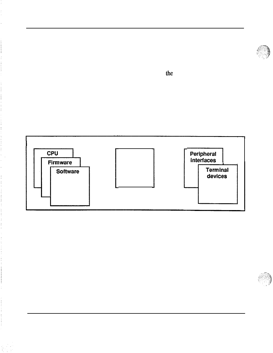
around three functional areas: Control, Switching, and Peripherals.
Control
The Control complex provides the sequences required by the system to
process voice and data call connections, monitor call activity, and perform
system administration, maintenance, and testing. It is composed of two
elements: the central processing unit (CPU) which directs lower level
subsystems in the hierarchy, and the system memory which stores the
operating programs.
Switching
The switching function is performed by the network equipment, which
interconnects terminal devices for communication with each other. The
network architecture is based on the concept of a digital multiplexed loop.
A loop is a bidirectional path between Network and terminal device which
transmits voice, data and signalling information.
System overview 553-3001-100
.d
10 System architecture
Peripherals
Peripheral equipment provides the analog and digital interfaces for all
peripheral devices, and performs analog to digital conversion of all input
signals before switching is performed by the Network. Additionally,
Peripheral equipment circuits provide the supervisory and transmission
functions needed for trunks connected to the external telecommunications
network.
Meridian 1 systems use a star topology for connecting peripheral devices to
the switching equipment, an approach which permits uniform distributed
wiring methods. This approach provides significant benefits in the area of
administration, installation, maintenance and reliability.
Figure 1
Meridian 1 modular architecture
Control Switching
Network
Circuits
Peripherals
-yjgjJ
Software architecture
The adaptability of software control provides a complete array of services
and features tailored to meet changing requirements.
Call processing, maintenance and administration of Meridian 1 systems are
controlled by software programs stored either as firmware programs, as
software programs resident in system memory, or as non-resident programs
on disk. The information which describes system configuration and
associated peripheral equipment is termed office data. This data resides in
the system memory and on disk.
System overview 553-3001-I 00
. .

System architecture
I
I
Firmware
.:;
These are fundamental programs consisting of hard-wired logic instructions
::
j
.,..“.
_....~
,‘;-T.>g
->yy
I
stored in Programmable Read Only Memory (PROM) which manipulate
:
;-“‘:
,
.
..~
. .
,’
data in the central processor and control input/output operations, error
:
diagnostic and recovery routines.
Software
Software programs consist of instruction sequences that control call
processing, peripheral equipment, administration and maintenance
functions. These sequences are interpreted by the fiiware programs into
machine instructions. Several generic software programs with optional
feature packages are available to satisfy varying requirements.
Office Data
The office data describes the characteristics of the system in terms of
configuration and call dependent information such as features and services.
Office data is arranged into blocks defining peripheral equipment, system
configuration and transient data. These data blocks permit configuration of
Meridian 1 systems to specific customer needs.
Resident Programs
Resident Programs are programs always available in memory during system
operation. Firmware programs control other resident programs and provide
all CPU arithmetic operations. The other resident programs are those which
are automatically loaded into the system memory from the disk drive at
system power-up. Once loaded, these programs remain in memory.
Non-Resident Programs
Non-Resident Programs are the overlay programs stored on disk which are
loaded into the “overlay area” of system memory when required to perform
specific tasks. Only one overlay program may be loaded at a time and is
removed from the overlay area when no longer required. Overlay programs
can be loaded automatically, under program control, or manually, via an
administrative terminal.
Once the user has logged into the system, commands for specific overlay
programs are processed by the overlay loader program. When loaded, the
overlay program assumes control. Only one administrative terminal can
input into the overlay arca at a time. More than one device, however, can
System overview 553-3001-l 00

12 System architecture
receive output simultaneously. A terminal may be configured as an input
only or
output
only device.
Overlay programs provide the system interface for maintenance, service
change, and traffic measurement. Each overlay program is independent and
has its own specific set of commands and formats. Overlay programs may
be run concurrently with normal call processing without interfering with
system traffic. There are five main categories of overlay programs:
Service Change and Print Routines
Service changes do not generally require hardware intervention. Instead,
the service administration programs are used to create or modify all aspects
of the system from individual feature key assignments to complete system
configurations. There are also programs and print routines for retrieving the
data from the system to check the status of office data assignments.
Maintenance Diagnostics
These programs are the primary instruments for maintenance purposes.
Individual programs are used for automatically or manually testing the CE
and PE. The programs may be loaded into the overlay area at the request of
maintenance personnel, or as part of a daily maintenance routine
automatically initiated by the system at a specified time. In addition,
background and signaling diagnostic routines can occupy the overlay area
-.-
when it is not in use.
Traffic
All systems are equipped with traffic data accumulation programs. There is
also a resident traffic print program which examines the schedules, transfers
data from accumulating to holding registers in accordance with schedules,
and prints the traffic data. In addition, there is a traffic overlay program
which is used to query and modify schedules, options, and thresholds.
Equipment Data Dump
After making service changes, the changes must be transferred to disk in
order to save them. When the equipment data dump program is invoked, all
the office data in the read/write memory is written to the system disk. The
data dump program is also used to install a new generic version or issue and
capture protected data store information which may be changed by the user,
such as speed call lists. The program may be invoked automatically during
System overview 553-3001-l 00
System architecture 13
.:
‘:i ;---
.:.,:,,
I
.,
_.’
!
a midnight routine or on a conditional basis (i. e. , data dump only occurs
if a software service change has been made). It may also be invoked
manually via the input/output (I/O) interface to the system.
Software Audit
This program monitors system operation and gives an indication of the
general state of the system operation. The program is concerned mainly
with the system software. When a software problem is encountered, the
program attempts to clear the problem automatically.
Hardware architecture
Each Meridian 1 system is composed of the following hardware
subsystems:
-
Common equipment (CE): Provides the device control, software
execution, and memory functions of the system.
-
Network equipment (NET): Performs the switching function under
CPU control.
-
Peripheral equipment (PE): Provides the interface for line and trunk
circuits.
-
Terminal equipment: Telephone sets and attendant consoles.
-
Power equipment Provides the electrical voltages required to operate
equipment.
Common equipment
Common Equipment (CE) consists of one or more Central Processing Units
(CPUs), memory circuits, and mass storage devices which control the
operation of the system. The CE communicates over a common control bus
which carries a constant flow of program instructions and data under direct
control of the CPU. The digitized speech signals follow a separate path on a
network switching bus which allows communications links to be established
between any of the peripheral devices.
-
The Central Processing Unit (CPU) provides the computing power
essential for entire system operation.
System overview 553-3001-l 00
z

14 System architecture
-
The system memory stores all operating software programs and data
unique to the particular Meridian 1 system, including switching
sequences, features, class of service information, and quantity and types
of terminals.
-
The Mass Storage Unit provides high speed loading of the operating
programs and data into memory.
-
The Digital Service Circuits provide functions such as dial and ringing
tones, and call conferencing capabilities.
-
The Serial Data Interface (SDI) provides a RS232C communications
link for administration and maintenance on either a local or remote
basis.
-
The Network Circuit Cards provide a digital matrix for circuit-switched
connections to associated peripheral devices.
Central Processing Unit (CPU)
The CPU performs the control and switching sequences required by the
system. The software that directs these functions is loaded into the system
memory from the mass storage unit by the CPU. Information flows
between the CPU, I/O devices, and the system memory over the CPU bus.
_
The data required by the CPU to perform its control and switching functions
is held during system operation in Random Access Memory (RAM) and fed
to the CPU via the CPU bus. The operating data is loaded into the RAM
from floppy diskettes on system power-up.
The CPU function is performed by circuit cards which include Read-Only-
Memory fiiware that contains fault clearing programs and instructions to
control the loading of system memory from the mass storage unit.
Meridian 1 systems incorporate a CPU design that is identical for most
system options.
-
24-bit data words plus l-bit parity
-
24-bit linear addressing that permits memory allocation to be assigned
on a contiguous basis instead of the 64K pages partitioning referenced
above
-
16M words
-
subdivided for up to 12M words of physical memory
space and a remainder of 4M words for I/O spaces
System overview 553-3001-100
System architecture 15
-
asynchronous (handshake) bus operation
-
16 file registers used to hold address and data for all operations
-
a sense (interrupt) input line to indicate that a particular device (tape,
TTY, PE) requires action by the CPU
-
a trap facility which, when activated by an external signal,
causes the
CPU to immediately begin executing instructions starting at a particular
address; this facility is used to enter a recovery routine when a fault is
detected
Mass Storage Unit
A mass storage unit equipped with two floppy diskettes and/or a Winchester
hard disk is used for high speed loading of the resident operating programs
and office data into system memory. The loading process is controlled by
instructions held in the Read-Only-Memory (ROM) fiiware. When
loading is complete, the diskettes remain in the mass storage unit to provide
a non-volatile store for automatic loading purposes in the event of software
being erased from memory during a power failure. Non-resident software is
loaded from the disk automatically or by manual request when required.
The Mass Storage Interface (MSI) card is designed to interface with
external devices that are compatible with the Small Computer System
.._
Interface (SCSI). This storage capability is provided by the following
hardware configurations:
-
NT8D68AA Floppy Disk Unit: two 3.5” 1.2 Mbyte floppy disk drives
(providing 2.4 Mbytes of formatted capacity) as a standard system
offering,
-
NTSD69 AA Multi Disk Unit: a Winchester Hard Disk with 10 Mbytes
of formatted capacity. When this option is equipped, the floppy disks
are used for backup and system loading.
System overview 553-3001-100
C.
16 System architecture
Both types of Mass Storage Unit (MSU) are compatible with any Meridian
1 system running Software Generic Xl 1 Release 8 or later. The upgrade
procedure involves replacing the Magnetic Tape Transport and associated
tape interface with the desired Mass Storage Unit and equivalent Mass
Storage Interface card (MSI) or Floppy Disk Interface (FDI) card. The
Mass Storage Unit requires the identical space required for the magnetic
tape unit, See
Disk drive
upgrade procedures
(553-3001-251) for more
information about disk drive upgrades.
Input
/
Output (I/O)
llnterfaces
There are various methods of communicating with Meridian 1 systems. A
family of Serial Data Interface (SDI) circuit cards provides from one to four
communication channels which conform to EIA Data Interchange Standard
RS-232-C. I/O addressing is under switch control of the
SD1
card and
allows up to 16 RS-232-C compatible devices, such as a terminals, to
communicate with the system. The devices are used to input commands
and/or receive responses from the system during administration and
maintenance procedures.
Memory
Firmware, software, and data are stored in a read/write Random Access
Memory (RAM). The memory is a critical part of the stored program
control system. It contains the memory stores of all of the basic operating
instructions for the system, plus data on the configuration of the particular
application being served. Memory utilization is dependent upon what
features are programmed into the system and the number of peripheral
terminations being served. The memory is split into four segments to
facilitate processor address purposes and permit a functional separation of
programs.
-
Unprotected Data Store
(LIDS):
These pages hold the transient or
unprotected data that is required during call processing. Included are
the timing queues and call registers.
-
Protected Data Store (PDS) : This protected data store holds the office
data blocks that are particular to specific installations.
Program Store (PS): Allocations within the Program Store are as
i.
-
:
.~
:.,
-..
a
follows:
:
.-a
./
System overview 553-3001-I 00
c
I
‘.
!
_‘:I .
.
.
2
_.
.
.
.
.- .
.
.
.
.
.
>. .
‘J
:
::‘
‘:<-i..,
‘,‘-.,--,:
‘:
.A,,
!
I
:
System architecture 17
Firmware
-
This portion of the memory is a non-volatile Read
Only Memory (ROM) used for storage of all system fiiware.
The ROM is programmed during manufacture and the instructions
are permanent and indestructible. It stores the basic rules of
operation necessary to initialize the system
and
bring it into a
working state. A recovery or “trap sequence” is included in
fiiware which is automatically invoked in response to power-on,
system reset, or when certain faults are detected.
Overlay
-
This portion of the memory may be loaded with
various non-resident programs as required during automatic
diagnostics, service order change, traffic measurement, or
maintenance.
Software
-
The remainder of this memory page is reserved for all
of the system software such as the call processing and optional
programs. Additional software storage capability is provided by
the incremental addition of more memory pages within this
category.
Input
/
Output Addresses
-
There are no RAM modules utilized
for this page. Instead the address range is reserved for
Input/Output (I/O) device addresses. These devices include
._
signaling for peripheral equipment along with magnetic tape and
terminal assignments.
Network equipment
Network equipment consists of network circuit cards which perform the
digital switching of voice and data signals, peripheral signalling cards which
perform scanning and signal distribution. , and service circuit cards, such as
tone and digit switches, which provide call progress tones and outpulsing as
instructed by the CPU. Network circuits employ Pulse Code Modulation
(PCM) and Time Division Multiplexing (TDM) to perform the switching
function.
Loops and Superloops
Network equipment interfaces with peripheral equipment via digital
multiplexed loops. A loop is a bidirectional path between Network
equipment (NET) and Peripheral equipment (PE) for voice, data and
signalling information. Upon commands from the CE, the network
establishes a path, linking a specific input to a specific output.
System overview 553-3001-l 00

18 System architecture
Meridian 1 systems provide two network circuit cards, the QPC414
Network Card which provides 2 loops per card, and the NT8DO4AA
Superloop Network Card which provides 4 loops per card, grouped together
in an entity called a Superloop. The Superloop permits all 120 ‘timeslots
provided by the network card to be shared among the peripheral devices
served by the superloop, providing higher traffic capacity and simplified
traffic engineering.
The flexibility of the network loop plays an important role in the Meridian 1
architecture. Besides the ability to increase circuit-switched bandwidth on
an incremental card basis for cost-effective growth, application may be
varied for
value
added services. The network structure allows for the full
connectivity of all devices irrespective of how they connect to the system.
The network loop is a key element in the implementation of Computer to
PBX Interface (CPI) and Digital Trunk Interface (DTI). CPI provides an
integrated interface for connecting large numbers of host computer ports via
24 channels each supporting up to 19. 2 kbps for asynchronous data or up
to 56 kbps for synchronous data. DTI provides a digital link of 24 channels
each of which may be flexibly allocated for both voice and data
communications. Both CPI and DTI use the North American T-l standard
(DS-1 format) and each equipped link is assigned an associated network
.-
loop.
Network organization
Network loops are organized into groups. Systems are configured as half,
full, or multiple group machines. A half network group machine provides a
up to 16 loops, a full group system provides from 17 to 32 loops, while a
multiple group system provides from 33 to 160 loops.
For applications beyond the traffic handling capability of the single network
group, additional switching stages are introduced to form a multi-group
arrangement. These connecting paths , provided by the InterGroup Module,
are merely an extension of the originating and terminating network loop
involved in a call. There are eight one way junctors from each group to all
others. Since each path provides thirty connecting channels, a total of 480
connection paths exist from one group to another
-
240 in each direction.
Five network groups may be interconnected to constitute a fully configured
digital switching matrix.
System overview 553-3001-l 00

System architecture 19
Network/Peripheral configuration
The allocation of peripheral equipment to the network loop determines the
traffic handling capability of the switching network. The lower the number
of terminations, the higher the loop traffic capacity. The quantity and type
of terminal assignments are allocated to optimize the traffic handling
capabilities of the switching network.
A universal PE bus structure permits any mix of PE card types to be located
in a PE module. Provisioning of PE cards and their associated density
(number of ports) determines the network loop to PE module configuration.
Complete modularity permits voice and data modules to be segregated so
that the specific traffic patterns of one may be met without impeding the
other.
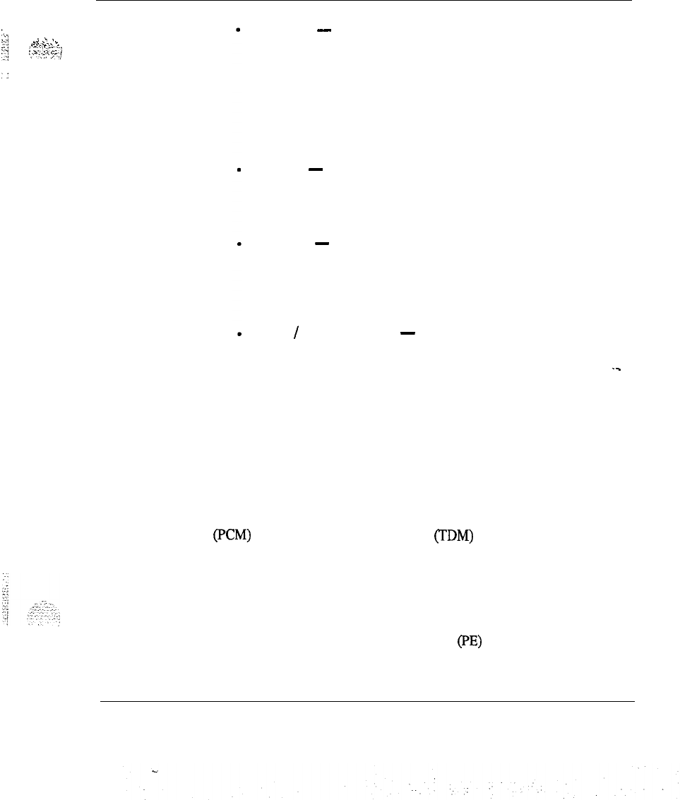
Enhanced Network Configurations
For peripheral equipment housed in NT8D13 PE modules, network capacity
may be allocated in single lcop mode and dual loop mode. In single-loop
mode, one peripheral equipment module is connected to one network loop,
yielding a maximum concentration of 160 terminations to 30 time slots. In
dual loop mode, half of the PE cards in a module use one loop, and the other
half use another loop, yielding two maximum concentrations of 80
terminations to 30 time slots.
System overview 553-3001-100
.
20 System architecture
Figure 2
Single and dual loop configurations
QPc414
ENET
Circuit
Pack
Network Loop
Network Loop
PE UEMIOR SHELF Two Network Loops
Connected To One
PE Shelf Containing
Single, Double Or
Quad Density PE
Ctrcuit Packs
PE UEMI OR SHELF
$F[
One Network Loop
Connected To Two
-PE Shelves Containing
Single Or Double
Density PE Circuit
Pa&s
PE UEMl OR SHELF
Combined
Single And Dual
Loop Connections
To Three PE Shelves
Containing Single Or
Double Density PE
Circuit Packs
System overview 553-3001-l 00

System architecture 21
Superloop Network Configurations
The Superloop Network Card combines four regular network loops to make
120 timeslots available to PE cards housed in Intelligent Peripheral
Equipment Modules. This increased bandwiath and larger pool of timeslots
increases the network traffic capacity by 25% for each 120 timeslot bundle.
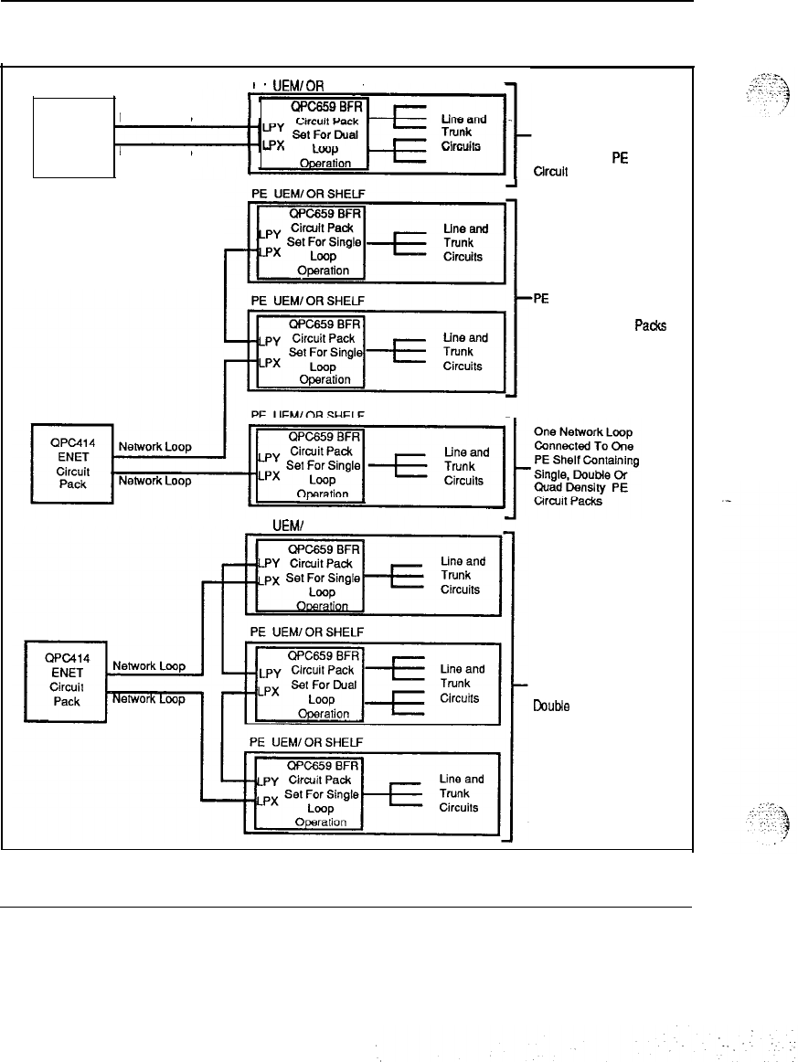
The NT8D37 Intelligent PE Module is divided into segments of 4 card slots.
These segments are numbered O-3. Segment 0 consists of PE slots O-3,
segment 1 consists of card slots 4-7, segment 2 consists of card slots 8-11,
and segment 3 consists of card slots 12-15.
A Superloop may be assigned from one to eight Intelligent PE segments. A
number of different superloop to segment configurations are possible. The
configuration chosen will depend upon system traffic requirements and the
specific PE cards used. Figures 4 through 9 illustrate different superloop to
segment configurations. Note that the TN to Timeslot concentration figures
(figure 3) are nominal, and may vary from segment to segment.
‘-
System overview 553-3001-100
22 System architecture
Figure 3
NT8D37 lntellegent Peripheral Module segmentation
segment
0
segment 1
segment2 --
Segment 3
Line Cards:
NTBWPAA Digital Line Card 16 to 32 TNs
NT8W3AA
Analog Line Card 16
MS
NTBDOSAA Message Waiting Line Card 16 TNs
TN density:
Per segment 16 iu 128 TNs
Per IPE module 64 to 512 TNs
Trunk Cards:
NTBD14AA Universal Trunk Card 8 TNs
NT8DlMA
E&M Trunk Card 4 TNs
Note: Maximum TN density assumes ail slots equipped with
NT8DMM
Diiital Line Cards with 16 voice and 16 data TNs
provisioned. Typical mix
of
line and trunk cards yields a
nor&al
density of 64 TNs per segment. 256 TNs per
IPE
module
System overview 553-3001-l 00
System architecture 23
,.‘i‘...
:::.--:.,
,\*
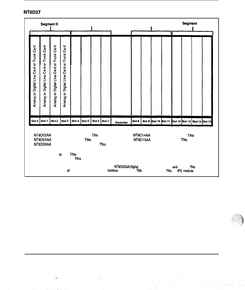
1 segment per Superloop
In this configuration, 1 segment is assigned to 1 Superloop (see Figure 4).
In cases where the segment is populated with NT8DO2AA Digital Line
Cards with all 16 voice and all 16 data TNs provisioned, the.1 segment per
superloop configumtion will provide a virtual non-blocking (120 Timeslots
to 128 TNs) environment (see Figure 2) Four NT8DO4AA Superloop
Network Cards and one NT8DOlAC Controller-4 Card are used to
implement a 1 segment per superloop configuration.
Figure 4
1 segment per Superloop configuration
segment
0
Segment
1
Ssgmem 2 Segment 3
I
I I
II
I
.:-__
.
?.
,
.-,
.:.:y
.:
-
..
.*I
System overview 553-3001-l 00
c
:
.
.
24 System architecture
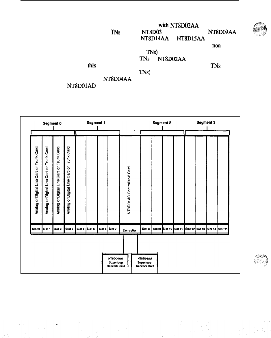
2 segments per Superloop
In this configuration, 2 segments are assigned to 1 Superloop (see Figure 5).
In cases where the segment is populated with NT8DO2AA Digital Line
Cards with no data TNs enabled, NT8DO3 Analog Line Cards, NT8Do9AA
Message Waiting Line Cards, or NT8D14AA or NT8D15AA Tnmk Cards,
the 2 segment per superloop configuration will provide a virtual non-
blocking (120 Timeslots to 32-128 TNs) environment (see Figure 2). For
instances where half of the data TNs on NT8DO2AA Digital Line Cards are
enabled, this configuration still provides a low concentration of TNs to
timeslots (120 Timeslots to 1% TNs) and a very low probability of
blocking. Two NT8DO4A.4 Superloop Network Cards and one
NT8DOlAD Controller-2 Card are used to implement a 4 segment per
superloop configuration.
Figure 5
2 segments per Superloop configuration
System overview 553-3001-100
System architecture 25
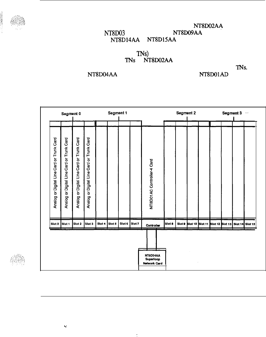
4 segments per Superloop
In this configuration, 4 segments are assigned to 1 Superloop (see Figure 6).
In cases where the segment is populated with NT8DO2AA Digital Line
Cards, NT8DO3 Analog Line Cards, NT8DO!JAA Message Waiting Line
Cards, or NT8D14AA or NT8DlSAA Trunk Cards, the 4 segment per
superloop configuration will provide a medium concentration (120
Timeslots to 64-256 TNs) environment (see Figure 2). In instances where
half of the data TNs on NT8DO2AA Digital Line Cards are enabled, this
configuration provides a concentration of 120 Timeslots to 384
TNs.
One
NT8DO4AA Superloop Network Card and one NT8DOlAD Controller-2
Card are used to implement a 4 segment per superloop configuration.
Figure 6
4 segments per Superloop configuration
System overview 553-3001-100
Y
:

26 System architecture
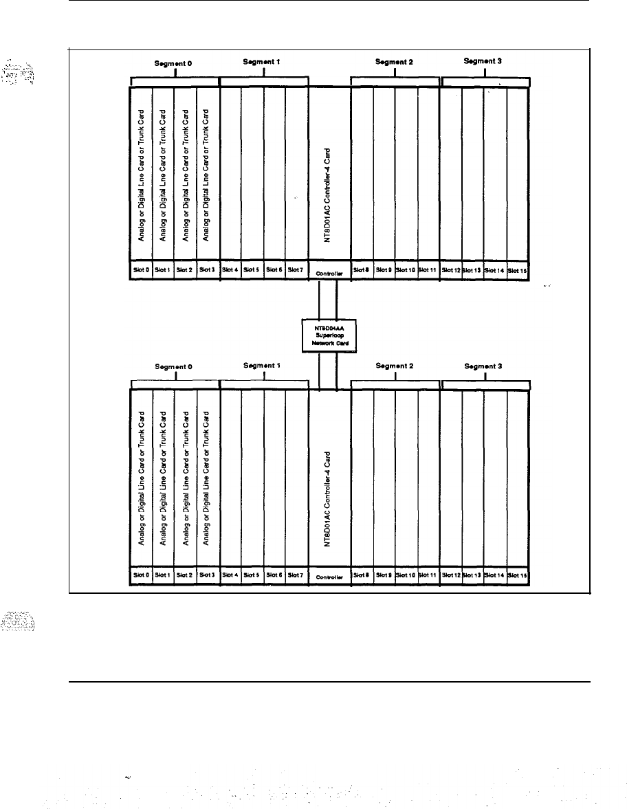
8 segments per
SUperlOOp
In this configuration, 8 segments are assigned to 1 Superloop (see Figure 7).
ln
cases where the segment is populated with NT9IO2AA Digit& Line
Cards, NT8DO3 Analog Line Cards, NT8DO!JAA Message Waiting Line
Cards, or NT8D14AA or
NT8DlSAA
Trunk Cards, the 8 segment per
superloop configuration will provide a high concentration (120 Timeslots to
128-512 TNs) environment (see Figure 2). In instances where half of the
data TNs on NT8DO2AA Digital Line Cards are enabled, this configuration
provides a concentration of 120 Timeslots to 768 TNs. One NT8DO4AA
Superloop Network Card and two NT8DOlAD Controller-2 Cards are used
to implement an 8 segment per superloop configuration.
System overview 553-3001-l 00
.
.
System architecture 27
..-
_
.:.y;-
_T.
I
,,
..:+
I,.
.
. .
.
_:,
:
-::
:
..T
.,
Figure 7
8 segments per Superloop configuration
System overview 553-3001-100
28 System architecture
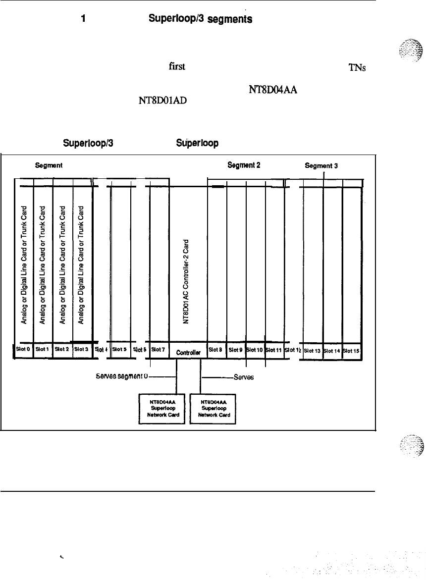
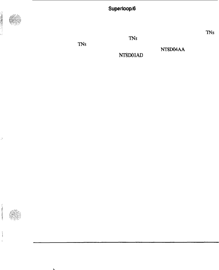
1
segment per
Superloop
segmenis per Superloop
In this configuration, 1 segment is assigned to 1 Superloop and an additional
3 segments are assigned to another Superloop (see Figure 8). This
configuration provides a virtual non blocking environment for the single
segment served by the
fiist
Superloop and a medium concentration of
TNS
to Tiieslots for the 3 segments assigned to the additional Superloop, as
described in the preceding examples. Two NT8DO4AA Superloop Network
Cards and one NT8DOlAD Controller-2 Card are used to implement a 1
segment and 3 segment per superloop configuration.
Figure 8
1 segment per Superloop/ segments per Stiperloop configuration
segmsnt 0
r
ir
Segment 1
I
lot4 JotI
r
ssgmml2
I
Cmtrdlr
-
nt,:
-Serves
segments l-3
System overview 553-3001-I 00
.
System architecture 29
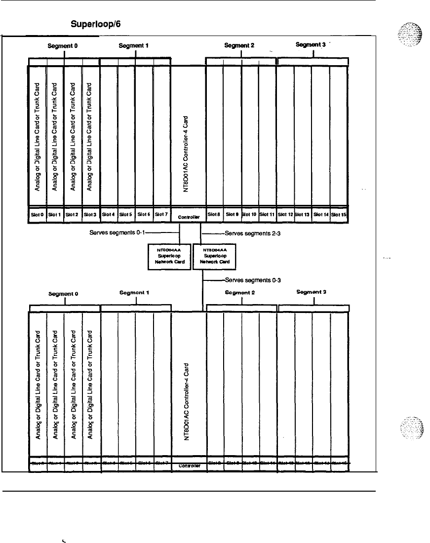
2
segments per Superloop/ segments per Superloop
In this configuration, 2 segments are assigned to 1 Superloop and an
additional 6 segments are assigned to another Superloop (see Figure 9).
This configuration provides a virtual non blocking environment for the two
segments served by the first Superloop (or a very low concentration of TNs
to Timeslots when some data
T’Ns
are enabled) and a medium concentration
of TNs to Timeslots for the 3 segments assigned to the additional superloop,
as described in the preceding examples. Two NT8DO4AA Superloop
Network Cards and two
NTSWlAD
Controller-2 Card are used to
implement a 2 segment and 3 segment per superloop configuration.
:
System overview 553-3001-100
.
30 System architecture
Figure 9
2 segments per
Superloop/
segments per Superloop configuration
System overview 553-3001-100
c
System architecture
31
Peripheral Equipment
Peripheral Equipment consists of peripheral controller cards which provide
the timing and control sequences for peripheral circuits, analog and digital
line and trunk cards, which provide the interfaces for terminal devices, and
circuit cards which provide Digital Trunk Interface (DTI),and Primary Rate
Access (PRA) services.
The peripheral controller performs the first stage of multiplexing signals
from the terminals, which are then passed on to the network for digital
switching. The peripheral controller also transmits timing signals, and
carries out other functions associated with the control of the peripheral
circuits.
The line card converts incoming analog signals into digital signals which
are then passed on to the peripheral controller. This conversion is
accomplished by an integrated encoder/decoder (codec) chip. There is a
codec for each port on the line card. Conversion from digital back to analog
is also performed by the codec for outgoing signals. For digital telephones,
the codec is located within the telephone set itself.
PCM
Pulse Code Modulation (PCM) is used to convert analog signals to digital
signals. The PCM method converts the analog signal to digital by samplin.g
the amplitude of the analog signal at a rate of twice the highest signal
frequency and converting the amplitude of each sample into a series of
coded pulses. The PCM sampling frequency standard for
telecommunications is 8 kHz.
Companding (compressing
-
expanding) PCM is a standard technique for
using 8 bits words to efficiently represent the wide dynamic range of voice
and data signals. Two standards for companding are internationally
recognized:
Mu-255 law for North American applications
A-law for international service
Meridian 1 codecs conform to both standards and are software selectable (in
Intelligent Peripheral Equipment Modules) for use in North America and
internationally. The codecs are also designed to pass signals up to 3.4 kHz
System overview 553-3001-100
.
.
32 System architecture
with minimum time delay and low phase distort&, a requirement for the
proper transmission of data signals.
Remote Peripheral Equipment (RPE)
In a local operating environment, the peripheral equipment may
be
housed
up to 50 feet from the common equipment. The RPE feature extends this
range to approximately 70 miles between local and remote facilities. This
extension is made possible by converting the multiplexed loop signals to a
form compatible with the commonly used T-l type digital transmission
system.
Any medium conforming to DS-1 format (1.544 Mbps) may be used to link
local and remote sites, including digital microwave radio and fiber optic
transmission systems.
DTVPRI
Allocation of circuit-switched bandwidth may also be made on a network-
loop basis to Primary Rate Access (PRA) or Digital Trunk Interface (DTI)
circuits. These optional services are based on the standard T-l format
(DS-1 24 channel) used in digital transmission networks.
DTI allows for the replacement of 24 conventional analog trunks by a single
T-l digital link. Each of 24 channels provides up to 56 Kbps for voice and
--
synchronous data transmission, or up to 19.2 Kbps for asynchronous data.
Power equipment
Meridian 1 systems feature a modular power distribution architecture which
parallels the modular design concept of the Universal Equipment Module.
Meridian 1 power systems provide the following features:
-
AC-powered and DC-powered system options, providing flexibility to
meet a wide range of customer requirements.
-
A distributed, modular power architecture, with power supplies located
in each Module, rather than in separate, centralized power shelves.
-
All DC systems are available as complete systems, with rectifiers
provided by Northern Telecom, or can be equipped for customer-
provided external power.
System overview 553-3001-100

System architecture 33
-
A new System Monitor has been designed to provide enhanced power,
cooling, and general system monitoring capabilities. This new System
Monitor interfaces to the CPU via a Serial Data Interface card, for
intelligent error and status reporting.
-
-
Maintenance messages that indicate the location of power faults and
status down to the specific Column and Module.
-
Equipment modules that are truly Universal, in terms of power and
cooling. Meridian 1 systems are designed to eliminate power and
thermal limitations: any card can go in any slot, and all modules can be
filled to capacity with any logically valid combination of cards, with
virtually no engineering rules.
-
A universal quick-connect power wiring harness is used to distribute
input voltages and monitor signals to power supplies located in each
Module.
.-
-
An advanced cooling system which employs forced air impellers. The
velocity of the impellers is automatically adjusted to meet the cooling
requirements of the system.
-
Fuses are eliminated, as the system exclusively uses circuit breakers for
input power protection.
-
Modular backup capabilities.
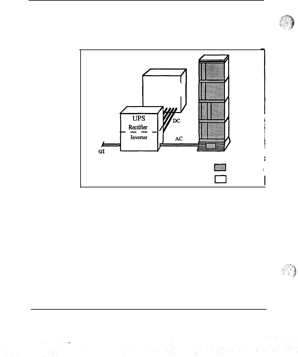
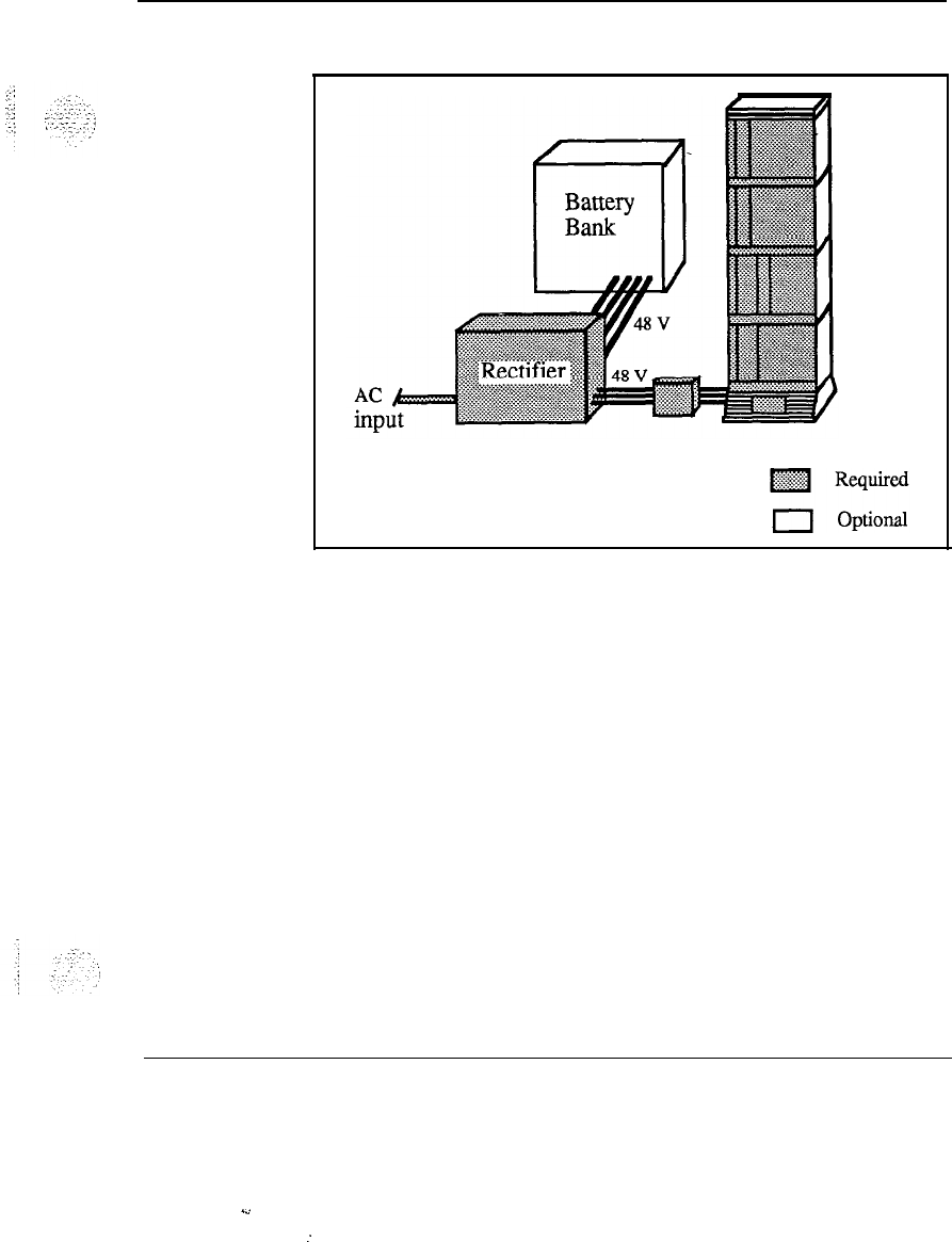
AC and DC systems differ primarily in the power components external to
the UEM. See Figures 8 and 9 for block diagrams of the AC and DC
powering schemes. DC systems always require the use of rectifiers. This
can be a disadvantage in applications that do not require reserve power
backup in the event of a utility power failure. The use of a rectifier in DC
powering is an advantage in applications that do require battery backup,
since all that is needed is to add batteries, as in the traditional central office
powering scheme.
AC-powered systems are especially well-suited for those applications that
do not require reserve power, as there are no external power components
required. There are a wide variety of Uninterruptible Power Supply (UPS)
systems available for AC systems that require reserve power, and the use of
a UPS is an effective method of providing backup power in many situations.
System overview 553-3001-100
34 System architecture
The choice of which powering scheme to use is determined primarily by
reserve power requirements and preferences, and by existing power
equipment at the installation site.
Figure 10
AC power architecture
I
Battery
Bank
I
w
UPS
DC
RkXXifkI
---
AC
inp
AC POWERED SYSTEM
(with reserve power )
,
‘
fgg
Required
i
--
0
Optional 1
,.--,-..
,:,..:
.i
:
.:
:
j
System overview 553-3001-100
System architecture 35
Figure 11
DC power architecture
DC POWERED SYSTEM
(with reserve power)
System overview 553-3001-l 00
.d
:

36 System architecture
System overview 553-3001-l 00
z..
:
:
37
Product description
.:;
,_
\
.y’..
1
:::
-:‘
.‘.
:
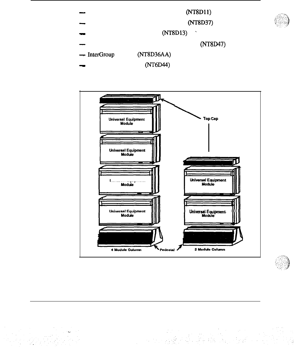
Universal Equipment Modules
The Meridian 1 System is comprised of Universal Equipment Modules
(UEMs), each containing everything needed (card cage assembly, power
supply, I/O cabling, etc) to support a specific system function. These UEMs
are assembled up to four high on a pedestal, to form a column. The pedestal
contains a central Power Distribution Unit (PDU), cooling fans, air filters,
and a System Monitor circuit. At the top of each column is a Top Cap,
which consists of two air exhaust grilles and a thermal sensor assembly that
works in conjunction with the System Monitor. Systems are comprised of
one or more columns. Each Universal Equipment Module is available in
AC or DC powered versions.
The Universal Equipment Modules are constructed of die cast aluminum,
providing strength and durability. For ease of access each module has
removable front and rear covers. All cable routing between the module and
the Main Distribution Frame (MDF) is handled through the rear of the
module. Cable exit can occur at the top, to access overhead cable racks, or
at the bottom to take advantage of raised floors. Universal Equipment
Modules are assembled on a pedestal that houses a central Power
Distribution Unit, cooling units and system monitor circuitry. The pedestal
can be equipped with either leveling feet or casters. UEMs may be
assembled in columns up to four high.
The following Universal Equipment Modules are available:
-
CPU module
(NTSD34)
-
CPU/Network module (NT6D39)
-
Network Equipment module (NT8D35)
System overview
553-3001-l 00
.
38 Product description
-
Common/Peripheral Equipment module
(NT8Dll)
-
Intelligent Peripheral Equipment module (NT8D37)
.
-
Peripheral Equipment module (NT8D13)
-
-
Remote Peripheral Equipment Carrier module (NT8D47)
-
InterGroup
module
(NT8D36AA)
-
Meridian Mail module
(NT6D44)
Figure 12
Universal Equipment Modules
Universal Equipment
\
Top-P
Univwbsl
Equipment
System overview 553-3001-l 00
Product description 39
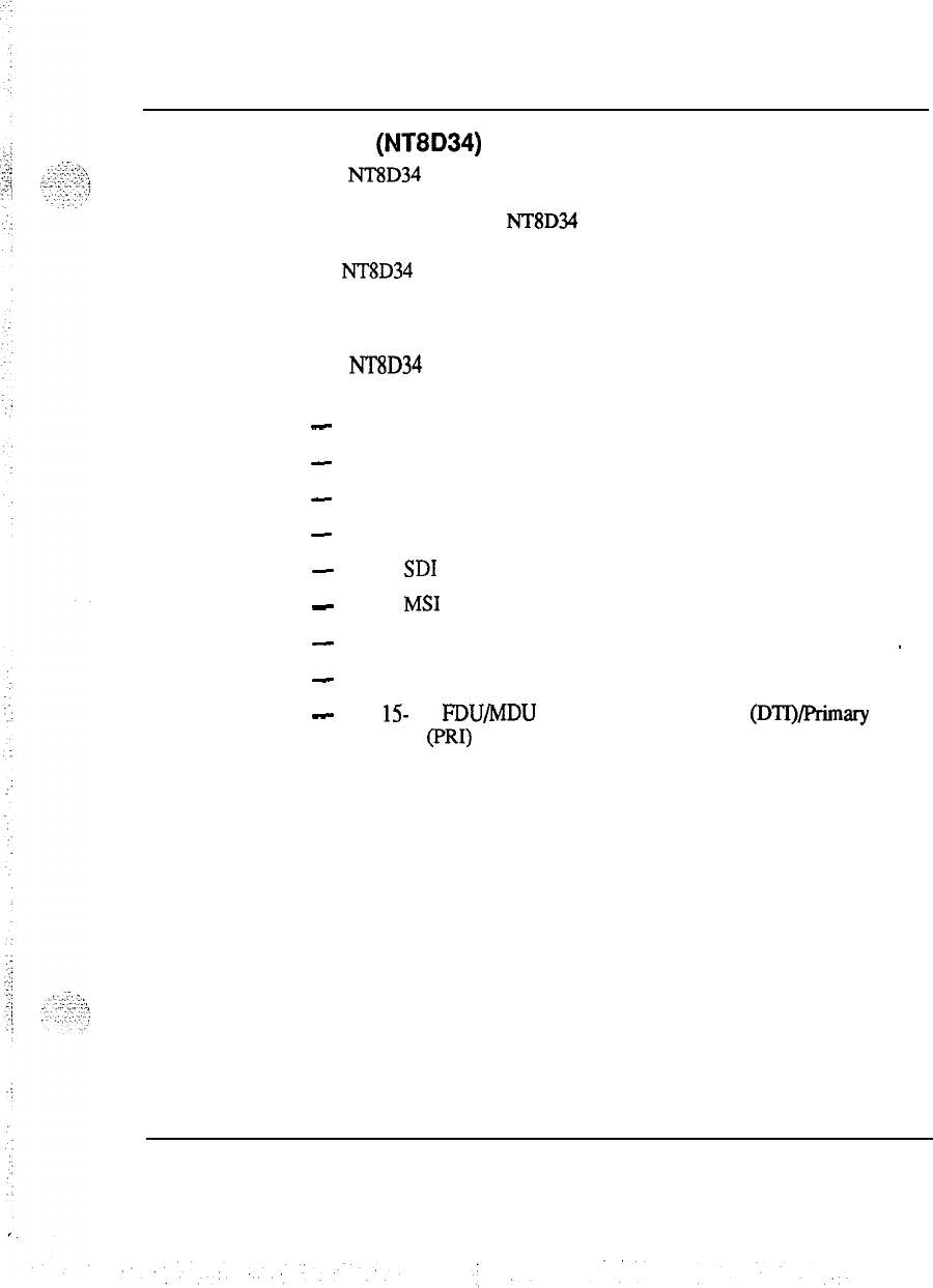
CPU module (NT8D34)
The NT8D34 CPU module houses the CPU and Memory cards used to
provide system control and storage of data and programs, for the Meridian 1
system option 71. Each NT8D34 CPU module houses one CPU; two are
required for the Meridian 1 system option 71. For configuration flexibility
the NT8D34 CPU module is available with an AC power supply option or a
DC power supply option. These power supplies provide the voltages to
operate the circuit cards located in the modules.
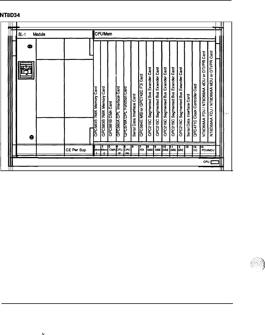
The NT8D34 CPU module contains 17 card slots which support the
following:
-
slots l-2 : Memory
-
slot 3: CMA
-
slot 4: CPU Interface
-
slot 5: CPU Function
-
slot 6:
SD1
-
slot 7:
MS1
-
slots 8-12: Segmented Bus Extender (SBE)
-
--
-
slot 14: Clock Controller
-
slot
15-
17: FDU/MDU or Digital Trunk Interface (DTI)jPrimary Rate
Interface (PRI)
System overview 553-3001-l 00
40 Product description
Figure 13
NT8D34 CPU module -typical configuration
I
-
!
SL-1
CE
Module
~CPU/Mem
Common Equipment
System overview 553-3001-100
c
Product description 41
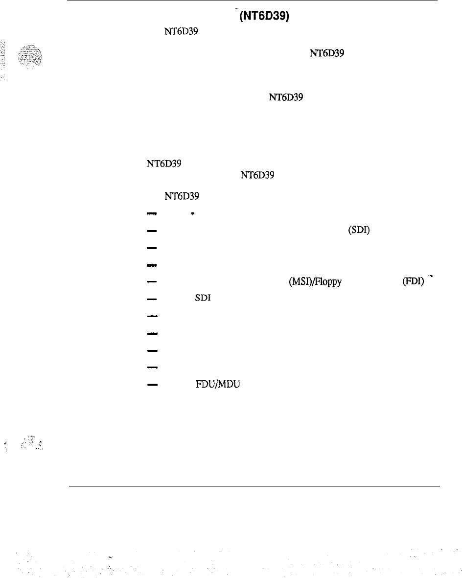
CPU/Network module
-(NT6D39)
The NT6D39 CPU/Network module houses the CPU and Memory circuit
cards used to provide system control and storage of data and programs for
Meridian 1 system option 51 and 61. Each NT6D39 module houses one
CPU and up to 16 network loops required for each Meridian 1 system
option 51 and 61.
For configuration flexibility the NT6D39 CPU/Network module is available
with an AC power supply option or a DC power supply option. These
power supplies provide the voltages to operate the circuit cards located in
the Modules.
For a half group, single CPU system (Meridian 1 system option 51) one
NT6D39 module is required. For a full group, dual CPU system (Meridian
1 system option 61) two NT6D39 Modules are required.
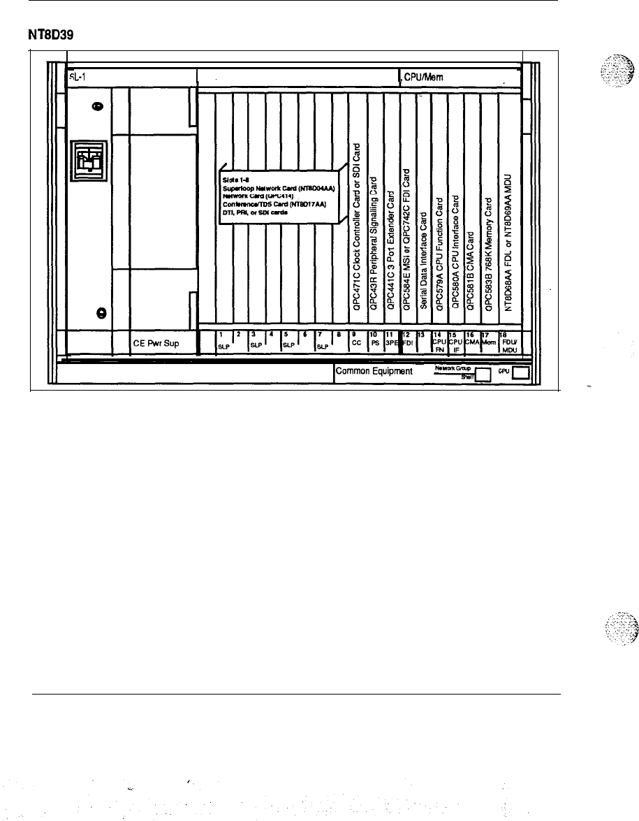
The NT6D39 contains 17 card slots which support the following:
-
slots 1
-
8: Network cards
-
slot 9 : Clock Controller or Serial Data Interface (SDI)
-
slot 10: Peripheral Signaling
-
slot 11: 3-Port Extender (3PE)
-
slot 12: Mass Storage Interface (MSI)/Floppy Disk Interface (FDI)
.-
-
slot 13:
SD1
-
slot 14: CPU Function
-
slot 15: CPU Interface
-
slot 16: Changeover Memory Arbitrator (CMA)
-
slot 17: Memory
-
slot 18: FDWMDU
!
_:..
.,
:
:
,
.;
.::
‘-1
.:
:
-.
1
System overview 553-3001-100
42 Product description
Figure 14
NT8D39 CPU/Network module -typical configuration
;L-1
CE Module
1
Net
I
CPUAkm
System overview 553-3001-l 00
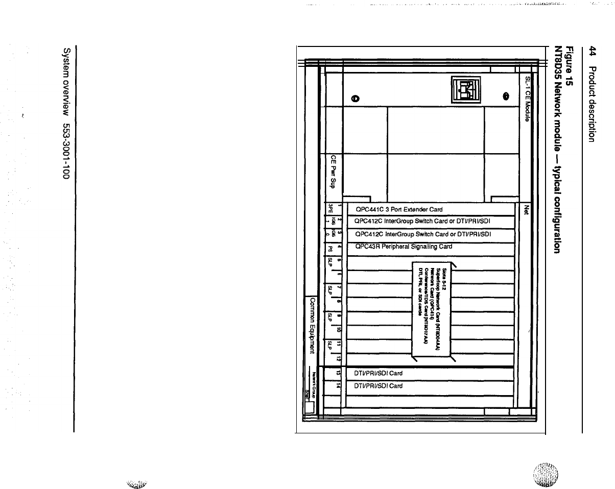
Product description
43
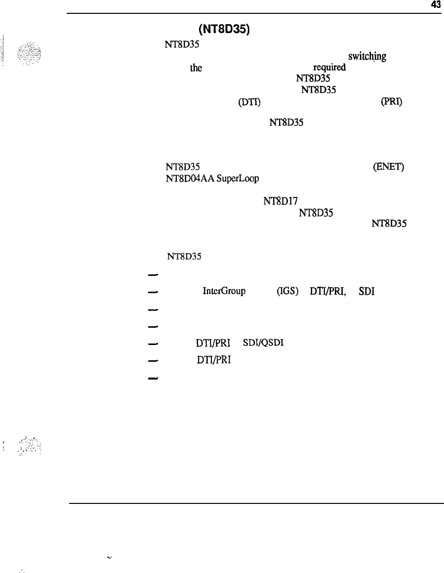
Network module (NT8D35)
The NT8D35 Network module houses the circuit cards which are used to
provide the digital multiplexed network loops of the switch.mg system,
along with the control and signalling cards
rquired
to interface the
switching function with the CPU. The NTSD35 Network Module is used in
Meridian 1 system option 71 only. The NT8D35 module also supports
Digital Trunk Interface (DTI) and/or Primary Rate Interface
@‘RI)
cards.
For configuration flexibility the NT8D35 Network module is available with
an AC power option or a DC power option. These power supplies provide
the voltages to operate the circuit cards located in the modules.
The NT8D35 Network module houses up to eight QPC414 (ENET) cards or
four NT8DO4AA SuperLoop Network cards, or any combination for a total
of 16 network loops per module. In a typical configuration, 14 voice/data
loops are available when one NT8D17 Conference/Tone and Digit Switch
card is configured in the module. Two NT8D35 modules are required to
make a full network group of 32 loops. A maximum of 10 NT8D35
Modules (5 network groups) may be configured.
The NT8D35 contains 15 card slots which support the following:
-
slots 1: 3PE
-
slots 2-3: InterGroup Switch (IGS) 1, DTWRI, or
SD1
-
slot 4: Peripheral Signaling
-
slots 5-12: Network Cards
-
slot 13: DTI/PRI or SDYQSDI
-
slot 14:
DTI/PRI
-
slot 15: not used
,i
1
j_::
..i-
..
i
:,
,,Y..
..‘,,
.
.
.
.
.
..‘.
!
,,.
/’
System overview 553-3001-100
Y
:.
Product description 45
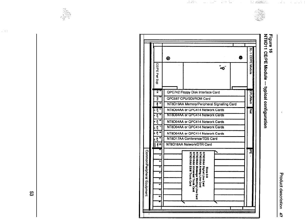
Common/Peripheral Equipment modute
(NT8Dli)
The
NT8Dll
module houses the common, network and peripheral
equipment circuit cards for Meridian 1 system options 21A and 21.
The
NT8Dll
CE/PE module is available
intwo
versions, AC or DC power.
These power supplies provide the voltages to operate the circuit cards
located in the modules.
The
NT8Dll
CE/PE module is divided into two functional sections:
-
Common Equipment (CE)
-
Peripheral Equipment (PE)
There are 10 Common Equipment (CE) and 10 Peripheral Equipment (PE)
card slots. The CPU functions are provided by card slots 1-3. The Network
Equipment functions are provided by card slots 3-10.
The
NT8Dll
module will utilize two specially designed circuit cards for
Meridian 1 System Options 21A and 21 only.
-
Memory/Signaling card (NT8D19AA)
-
provides the peripheral
signaling functions in addition to providing the memory and
miscellaneous CPU equipment functions.
-
Network/DTR card (NT8D18AA)
-
provides the Controller card
--
(NT8DOl) functions for the Intelligent PE cards installed in the
NT8Dll
module, along with a SuperLoop Network and Digitone
Receiver functions.
The NTSDl 1 module uses the new Intelligent Peripheral Equipment cards
to provide trunk and station interface in system options 21A and 21.
System overview 553-3001-100
46 Product description
The
NT8Dll
CE/PE Mod&e contains 20 card slots which support the
following:
-
slot 1 : FDI
-
slot 2 : CPU
-
slot 3: Memory
-
slots 4-8: Network cards
-
slot 9: Conference/Tone and Digit Switch card (N’lXD17AA)
-
slot 10: Network/DTR card (NT8D18AA) (Always configured
as SuperLoop 28)
-
slots O-9: Intelligent Peripheral Equipment cards only
System overview
5!53-3001-100
.
.
.-.;
:,::,
:
,.
,:,_
,:,:,+
,..
:(
.!
48 Product description
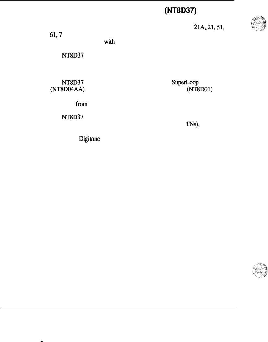
Intelligent Peripheral Equipment module (NT8D37)
The Intelligent Peripheral Equipment module uses the new Peripheral
Equipment cards only and may be used with system options 21A,.21,51,
61,7
1. With an upgrade assembly the Intelligent Peripheral Equipment
modules may be used with all existing systems.
The NT8D37 Intelligent PE module is available in two versions, AC or DC
power. These power supplies provide the voltages to operate the circuit
cards located in the modules.
The NT8D37 module may only be connected to a SuperLoop Network
(NT8DO4AA) circuit card. It houses one Controller card (NT8DOl) and up
to 16 Intelligent Peripheral Equipment circuit cards. The card slots are
numbered from 0 to 15, for a total of 16 PE card slots.
The NT8D37 Intelligent PE module supports 16 PE circuit cards, yielding a
capacity of 256 Integrated Voice/Data (IVD) lines (512 TNs), although a
typical configuration includes a mixture of Digital lines, Analog lines,
Trunks and Digitone Receiver (DTR) circuit cards.
All cable connections to the MDF are made in the rear of the module
through an I/O panel. To serve all 16 PE card slots, 12 PE cables are
required to the MDF.
System overview 553-3001-100
.
Product description 49
Figure 17
NT8D37
Intelligent PE module-typical configuration
0
1
IPE
@
LJ
PE Pwr Sup
II
.
System overview 553-3001-100
.
.

50 Product description
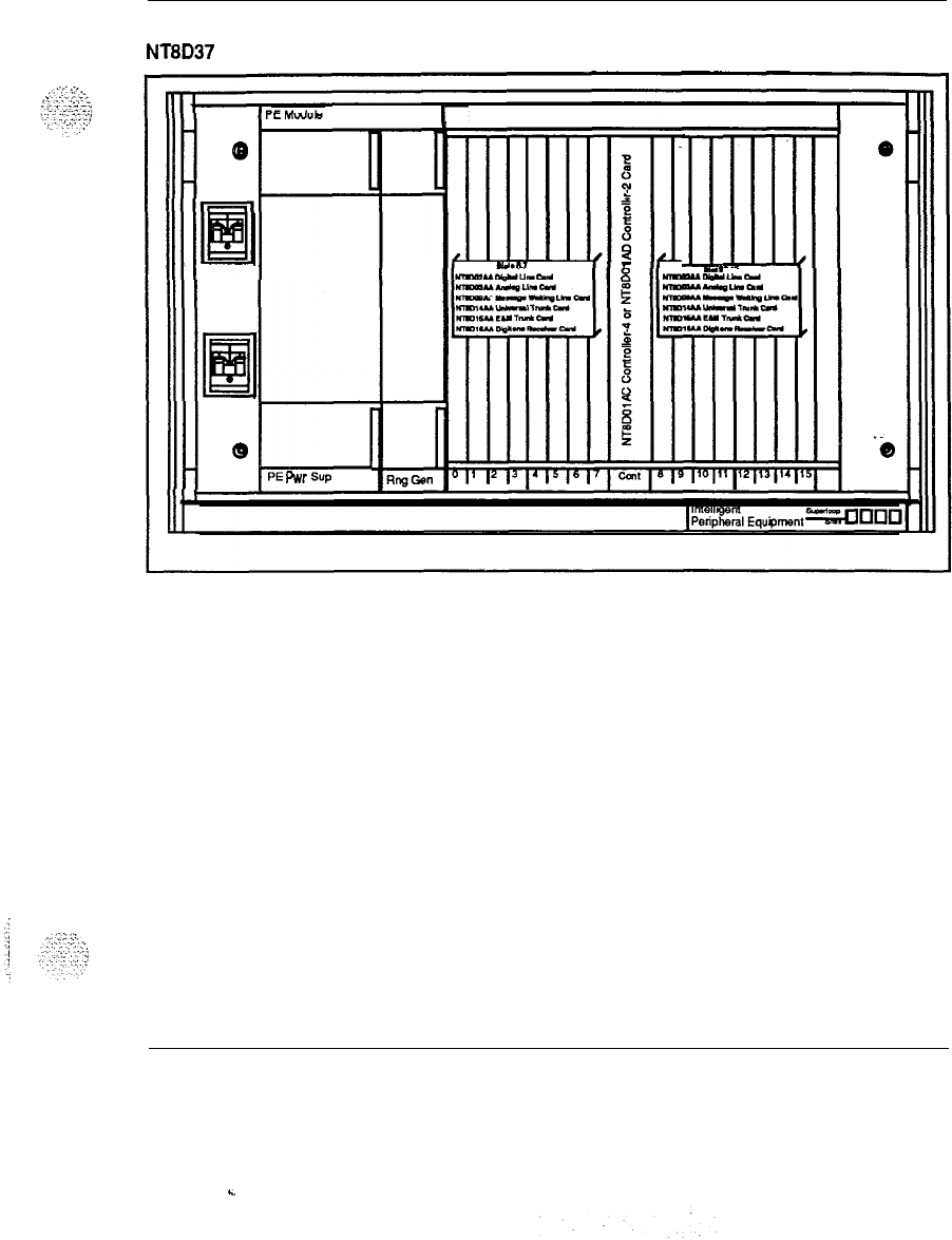
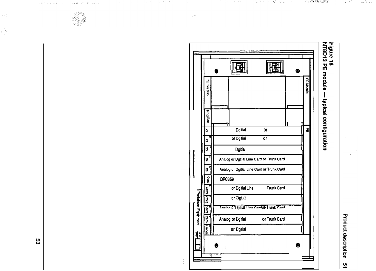
Peripheral Equipment module (NT8D13)
The Peripheral Equipment module uses the PE circuit cards currently
housed in PE shelves for the Meridian SL-1 systems. It provides the
interface to the system for trunks and stations. The NT8D13 module may
only be connected to an ENET (QPC414) circuit card and maybe used in
system options 21A,
21,51,61,71
and the Meridian SL-IXT, NT, RT, ST,
N, and XN systems. It houses one Peripheral Buffer circuit card (QPC659)
and up to ten existing peripheral equipment circuit cards.
When the Meridian Data Service ADM, SADM, ASIM or AIM are required
on system options 21A,
21,51,61,
and 71, the NT8D13 PE module must be
used.
For configuration flexibility the NT8D13 Peripheral Equipment module is
available with an AC power supply option or a DC power supply option.
These power supplies provide the voltages to operate the circuit cards
located in the Modules.
All cable connections to the MDF are made in the rear of the module
through an I/O panel. Seven PE cables are required to the MDF for all 10
card slots.
System overview 553-3001-l 00
.
.
$
F
I
I
?
Analog or Dgital Line Card or Trunk Card
*
I
Analog or Dgilial Line Card cr Trunk Card
It-l
5
Analog or Dgital Line Card or Trunk Card
II
211
WC659 Peripheral Buffer Card
-II
Iill
Analog or Dgillal Line Card or TrunkCard
B
I
$
ltlt
3
Analog or Dgtial Line Card or Trunk Card
Analog or
Dgflial
Line Card or Trunk Card
Analog or Dgltial Line Card or TrunkCard
Analog or Dgltial Line Card or Trunk Card
II
52 Product description
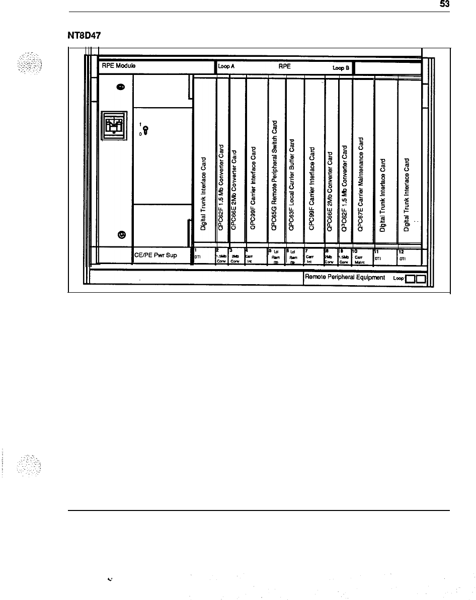
Remote Peripheral Equipment Carrier module (NT8D47)
The NT8D47AA/DC RPE Carrier module is used to extend the Network to
PE interconnection distance between local and remote sites. It,
1
accommodates two network loops. The number of modules required per
system depends on the number of stations in the remote site.
For configuration flexibility the Remote Peripheral Equipment Carrier
module is available with an AC power option or a DC power option. These
power supplies provide the voltages to operate the circuit cards located in
the modules.
The RPE backplane contains 12 card slots which support the following:
-
slot 1: DTI
-
slot 2: 1.5 Mb Converter
-
slot 3: 2 Mb Converter
-
slot 4: Carrier Interface
-
slot 5: Remote Peripheral
-
slot 6: Local Carrier Buffer
-
slot 7: Carrier Interface
-
slot 8: 2 Mb Converter
-
slot 9: 1.5 Mb Converter
-
slot 10: Carrier Maintenance
-
slots 1 l-12: DTI
System overview 553-3001-l 00
Product description
53
Figure 19
NT8D47
RPE Carrier module -typical configuration
System overview 553-3001-100
%.
54 Product description
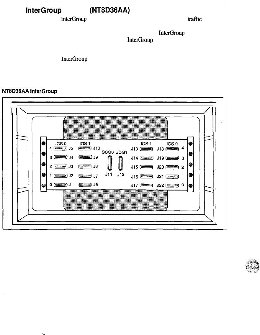
InterGroup
module
(NT8D36AA)
The InterGroup module provides a path for the switching of traflic between
the network groups in system option 71. Faceplate cables from Segmented
Bus Extender (SBE), System Clock (SCG) and InterGroup Switch (IGS)
circuit cards are connected to the InterGroup module. These faceplate
cables are accessed from the front of the module.
The InterGroup module does not require any power card for operation.
Therefore it may be used with systems using the AC power option or the
DC power option.
Figure 20
NT6D36AA
InterGroup
module
I
I\
/II
System overview 553-3001-l 00
.
.
Product description 55
I./ ;:.
..:,=-,
._
./
I..
.,
j!
II
--.--x..:~:;
-.
. .
.
.
.
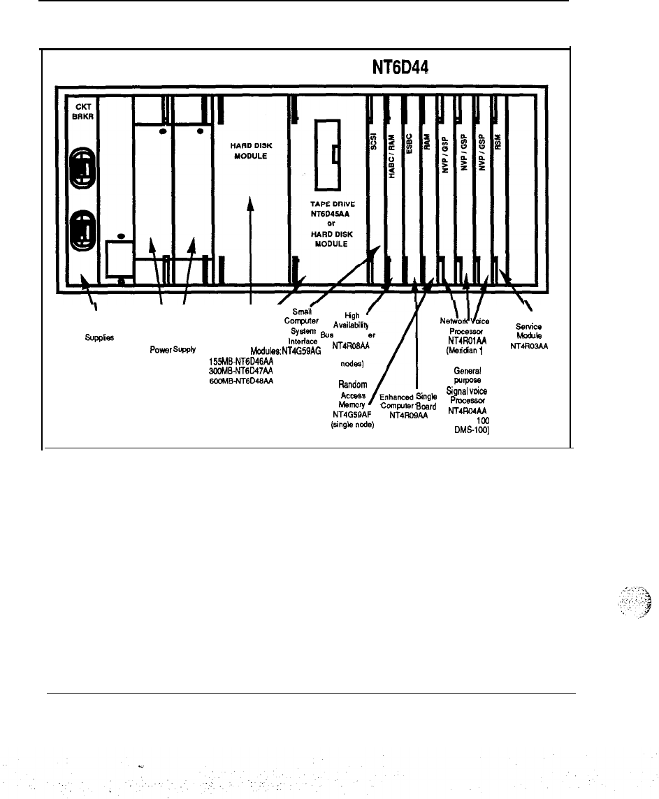
Meridian Mail module (NT6D44)
The NT6D44 Meridian Mail module houses the circuit cards currently used
by the Meridian Mail Option for Meridian SL-1 systems: The NT6D4.4
Meridian Mail module may only be connected to an ENET (QPC4 14)
circuit card and may be used in Meridian 1 system options 21A,
21,51,61,
71 and the Meridian SL-1 XT, NT, RT, ST, N, and XN systems.
For configuration flexibility the NT6D44 Meridian Mail module is available
with an AC power supply option or a DC power supply option. These
power supplies provide the voltages to operate the circuit cards located iu
the Modules.
Meridian 1 system option 21A must be upgraded to Meridian 1 system
option 21 when the NT6D44 Meridian Mail module is equipped.
System overview 553-3001-100
c
:
.
.
56 Product description
Figure 21
Meridian Mail module
-typical configuration
MERIDIAN MAIL MODULE
NT6D44
. .
\
Circuit breakers
\I V
smdr
/
for Power
corrputer
&h
Availabiliiy
N.h!oJLe
’
RS-232
,;;;ym
Bus
Controller
PIDCWSU
.setice
sup+3
Common Equipment
wle
Power
St&ply
Hard Disk
Modules:
NT4G5QAG NT4RO6M NT4RolAA
(multiple (Maidan
1
NT4ROW
155MB-NT6D46AA
2OOMBNT6D47AA ncdes)
/I
or
GMWd
6OMB.NT6D46AA or
Random
wrpo=
AC-8
Enhanced Single signal
vcica
Memory CcmpMer
Eloerd PfOWstuw
NT4G5gAF NT4ROBAA NT4RwAA
(sing*
de)
(Meridian tW
or DMS-loo)
System overview 553-3001-100
Product description
57
Pedestal (NT8D27AB)
The NT8D27AB pedestal is a base unit made of die-cast construction and
houses the power distribution unit, system monitor, blower unit, and fan
unit connector. One pedestal is required per equipment column.
The pedestal is approximately 31.5 inches wide by 25.50 inches deep by 10
inches high and weighs 30 lbs empty. Leveling feet are provided for up to
four tiers, while a caster option is provided for up to two tiers. Input power
for the system is brought into and distributed by the pedestal. A Power
Distribution Unit located in the pedestal contains an EMI filter and one 30
amp circuit breaker.
One pedestal distributes the input power for one column. Also located in
the pedestal are two forced air impellers and a reusable dust filter. The
impellers are protected by two 1 amp circuit breakers.
Top cap
(NT7DQO)
.-
The top cap is mounted on the top module of each column. It provides
additional EM1 shielding, air exits, and I/O cable exits.
The top cap is approximately 31.5 inches wide by 22 inches deep by 3
inches high and weighs 8 lbs. It consists of a front and a rear air exhaust
grills, each secured by two clips underneath the edge of the grill.
._
Three versions of the top cap are available:
-
NT7DOOAA AC systems
-
NT7DOOBA DC systems
-
NT7DOOAB Meridian 1 System option 21A only
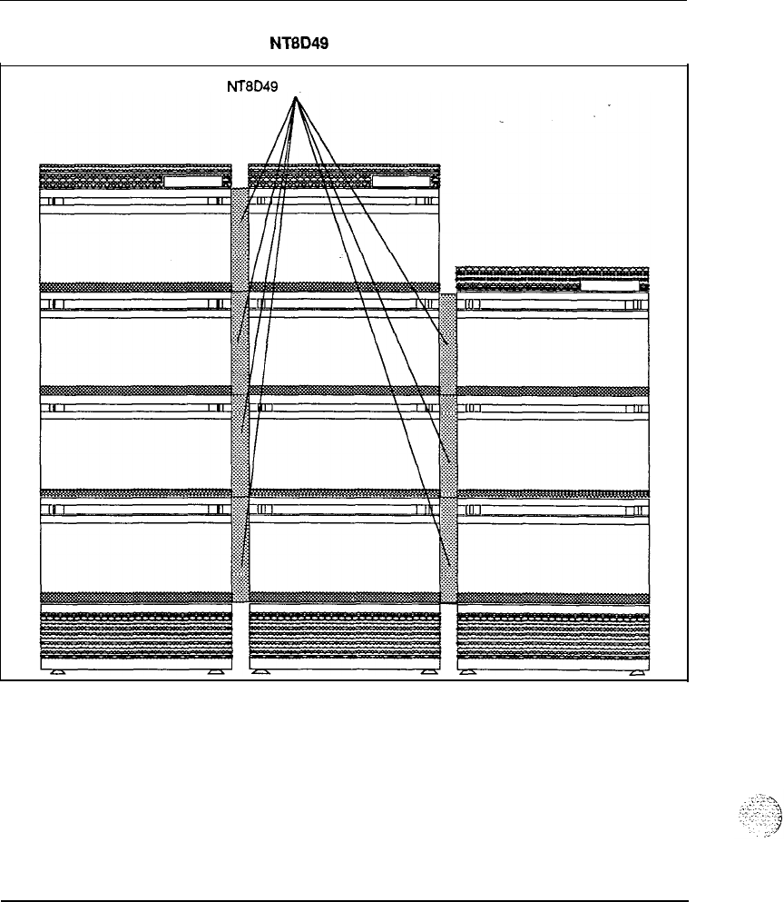
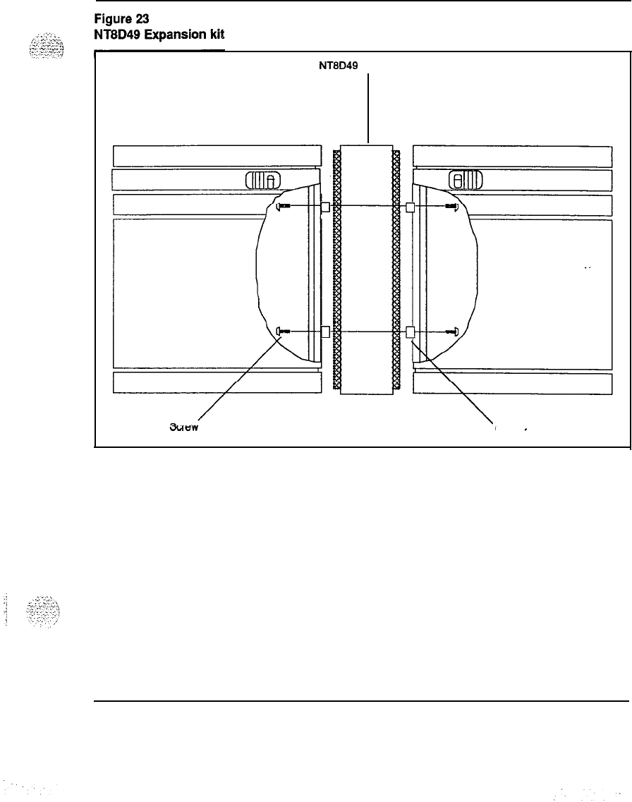
Expansion kit (NT8D49)
The Expansion kit bolts modules together for side-by-side expansion when
in a contiguous row. The Expansion kits also maintain shielding against
EMI/RFl. See Figures 22 and 23.
System overview 553-3001-100
58 Product description
Figure 22
Multi-column system equipped with NTBD49 Expansion kits
NT8D49
Expansion
Kits
System overview 553-3001-l 00
Product description 59
NT8D49 Expansion Kit
Spacer
System overview 553-3001-l 00

60 Product description
Meridian 1 system options
Several system options are available. The use of the Universal Equipment
Modules allows for seamless growth from one option to another by adding
or replacing Universal Equipment Modules or card cages. The options are
selected depending upon the application, line size, and other customer
requirements:
-
Meridian 1 system option 21A
-
Single CPU-l module only
-
Meridian 1 system option
21-
Single CPU
-
Meridian 1 system option
51-
Single CPU, Half Network Group
-
Meridian 1 system option
61-
Dual CPU, Full Network Group
-
Meridian 1 system option
71-
Dual CPU, Multiple Network Groups
Meridian 1 system option 21A
The Meridian 1 system option 21A package includes the CE/PE base
hardware, 1 Network/DTR card, 1 Conf/TDS card, 1 Floppy Disk Unit
(FDU), 2
SD1
paddle boards. The Pedestal and Top Cap assemblies must be
added. These assemblies include a Top Cap-21A, System Monitor-21A,
Pedestal, AC power cord and a power distribution Unit-21A. The Meridian
1 system option 21A supports only the AC power option.
Figure 24
System option 21 A
System overview 553-3001-I 00
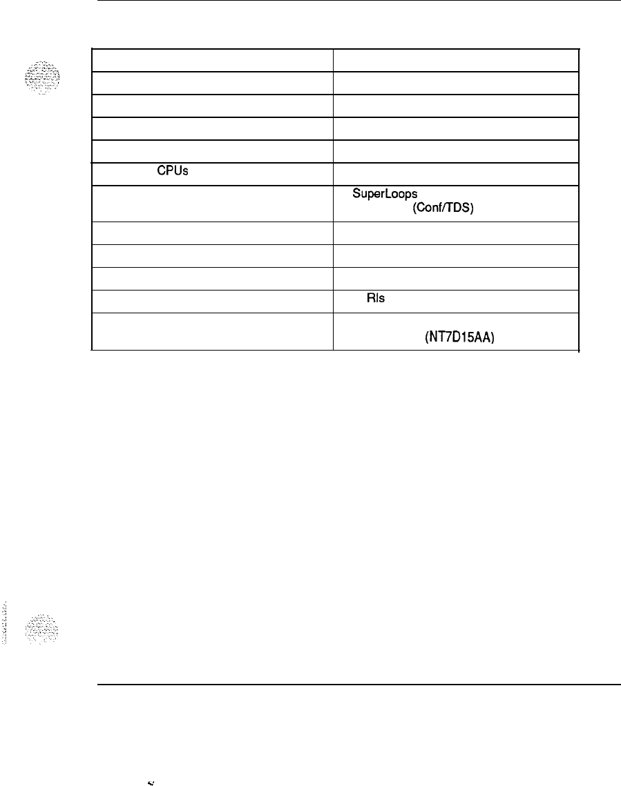
Product description 61
Table 1
System
option 21A specifications
Power
Typical Number of Ports
Maximum Number of Ports
Maximum Number of Modules
AC Input Voltage
Number of CPUs
Number of Network Loops
l
Cooling
Memory
Data Storage
Software Generic
Hardware Features
AC only
160
320
1
208
V ac
1
7 SuperLoops or 12 ENET Loops plus two
service loops (Conf/TDS)
Fan in Top Cap
768K
Floppy Disk Unit
1011 Rls 15
No Power Distribution Unit Contains
System Monitor (NT7D15AA)
Note:
Additional network loops require expansion modules
(Intelligent PE or Peripheral Equipment Modules).
System overview 553-3001-100
Y
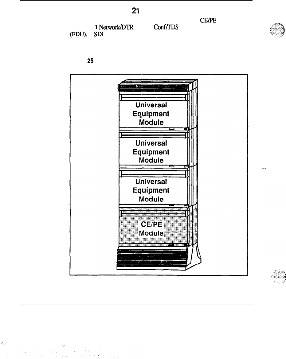
62 Product description
Meridian 1 system option
21
The Meridian 1 system option 21 package includes the CEjPE base
hardware,
1
Network/DTR card, 1 Conf/TDS card, 1 Floppy Disk Unit
(FDU), 2
SD1
paddle boards. The Pedestal and Top Cap assemblies must be
added. Figure 25 illustrates a typical configuration with the shaded area
showing the base package.
Figure
25
System option 21
System overview 553-3001-100
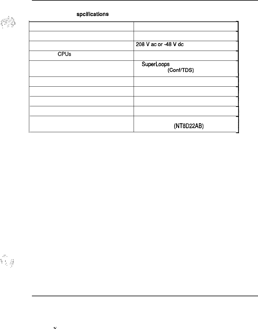
.;.
_,
,‘)
2;:
‘,i,
,’
.”
.
..’
,y
-.
:,
,-,z
;..
‘:.
3
,::
:
..,
._,!
.)
Product description 63
Table 2
System option 21 spcifications
Power
Maximum Number of Ports
Input Voltage
Number of CPUs
Number of Network Loops
Cooling
Memory
Storage Media
Software Generic
Hardware Features
AC or DC
800
208Vacor-48Vdc
1
7 SuperLoops or 12 ENET Loops plus two
service loops (Conf/TDS)
Fan Impellers in pedestal
768K
Floppy Disk Unit
1011 Rls 15
Standard Power Distribution Unit Contains
System Monitor (NT8D22AB)
System overview 553-3001-l 00
c
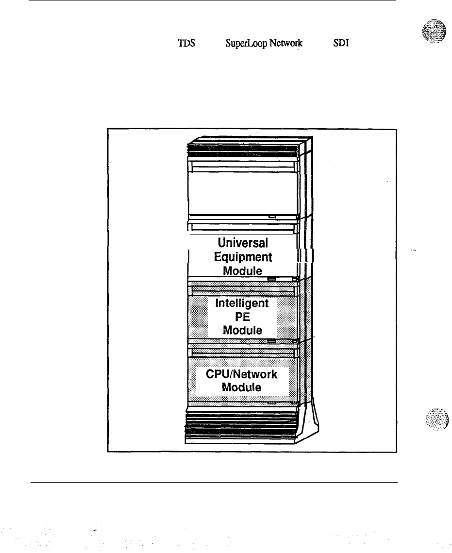
64 Product description
Meridian 1 system option 51
The Meridian 1 system option 51 package includes 1 CPU/Network module,
1 Conference and TDS card, 1 SuperLoop
NetworJc
card, 2
SD1
paddle
boards, 1 Intelligent Peripheral Equipment module, 1 Pedestal assembly
and 1 Top Cap. The FDU or MDU assembly must be added. Figure 26
shows a typical system configuration with the shaded areas showing the
base package.
Figure 26
System option 51
I
Universal
Equipment
I
Module
u
r
Ufliversal
‘tlll
Equipment
1111
System overview 553-3001-l 00
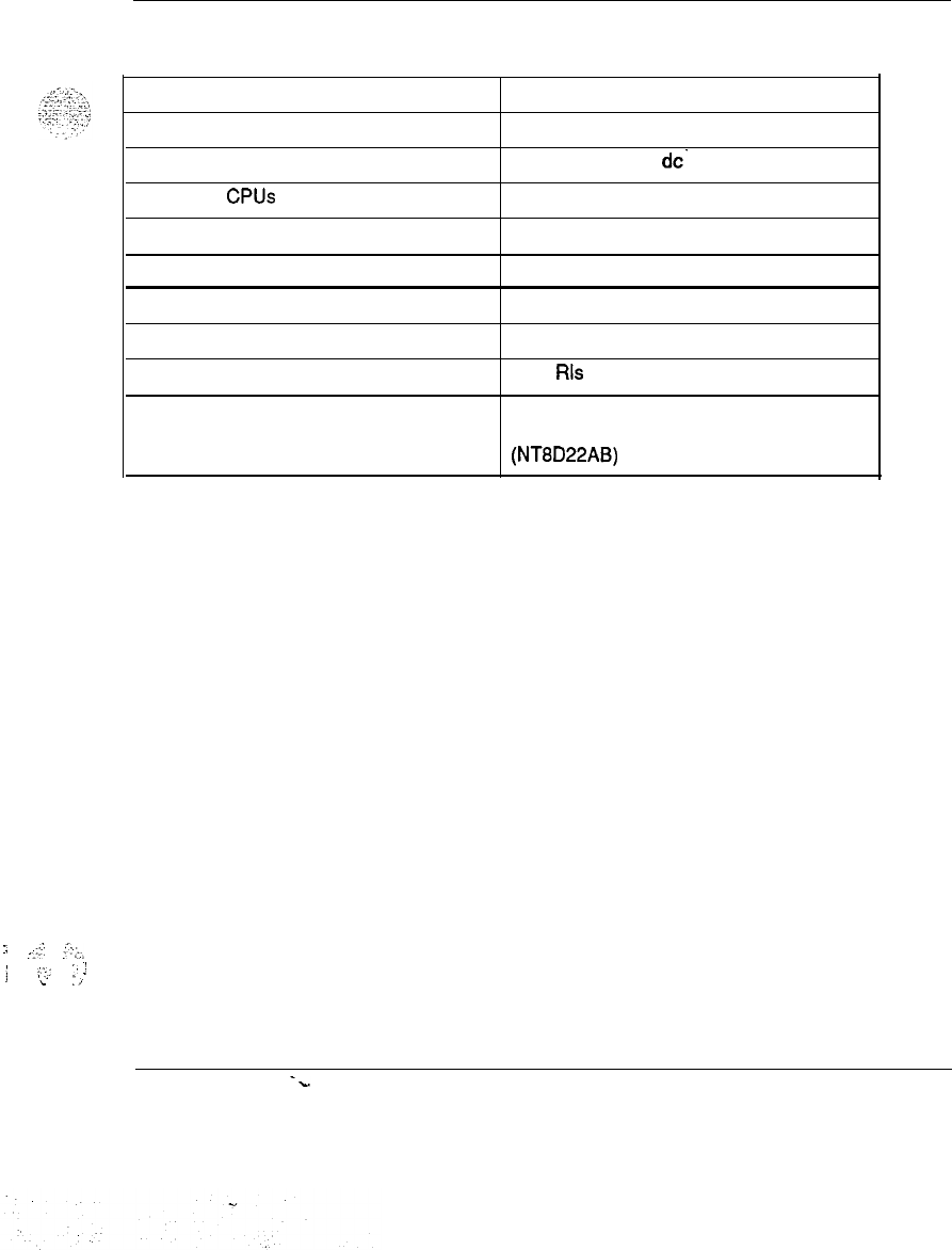
:,
..-:.-
‘:;.
.;
-‘.,.
:
‘:
!
‘L
:,
Product description 65
Table 3
System option 51 specifications
Power
Maximum Number of Ports
Input Voltage
Number of CPUs
Number of Network Loops
Cooling
Memory
Storage Media
Software Generic
Hardware Features
AC
or DC
1000
208 V ac or -48 V
dc-
1
16
Fan Impellers in pedestal
768K
Floppy Disk Unit
or
Multi Disk Unit
1111 Rls 15
One Half Network Group, Standard Power
Distribution Unit Contains System Monitor
(NT8D22AB)
System overview 553-3001-100
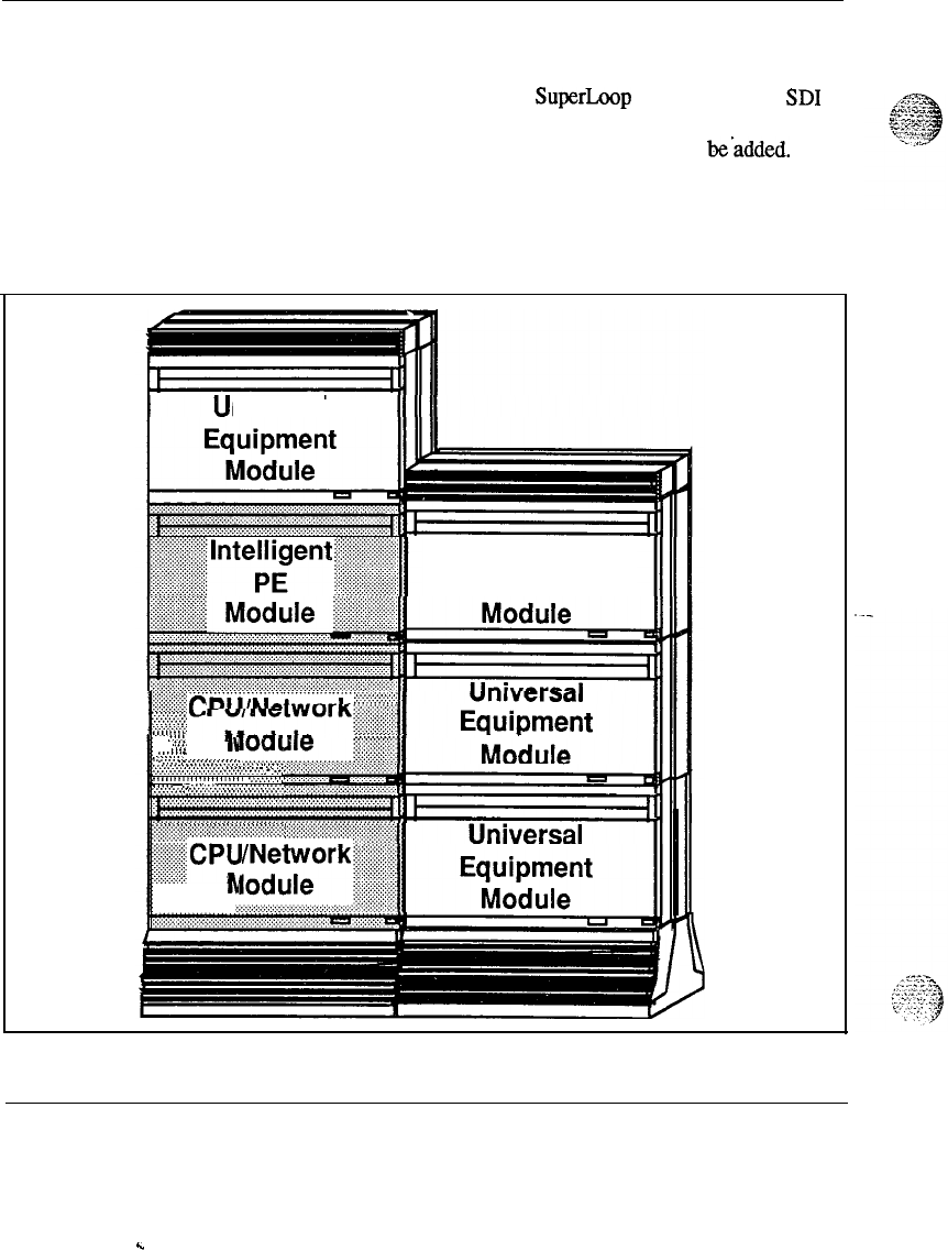
66 Product description
Meridian 1 System option-61
The Meridian 1 System option 61 package includes 2 CPU/Network
Modules,
2 Conference and TDS cards, 1 SuperLoop Network card, 2
SD1
paddle boards, 1 Intelligent Peripheral Equipment module, 1 Pedestal
assembly and 1 Top Cap. The FDU or MDU assembly must be.added.
Figure 27 shows a typical system configuration with the shaded areas
showing the base package.
Figure 27
System option 61
niversal
Universal
Equipment
~g”“‘&‘~y~~~
.................
........
I-~:::~~
::::::::i:;:::i:
r
........
.. .... ..
.........
.. .... ... .
.......
.. .... ... ..
......
.. .... ...
........
IY
..
............. .
.
........
..
......................
.
.
.. ... ... .
.
.
.:.~:...:...:.:.:.::::::::
::::.:.:.~.:.:.:.:.:.:.:.:.:.:.:
..
:.: .....
.................
~~:(
._,
.. ..:
.>
......................
...........
.............................
..... .........
............
..:.:.:.:.:.:.:
.: ........
.............................
........ ..................
.
................................
iiiiiiiiiii~~~~~~~~~~~~~~~~~~.~~~~~~~~~~~~~~~~
~CPl-
--
..........
. ii
.........
. .
. .....
h
........
..........................
....................
.....................
....................
System overview 553-3001-l 00
.
.
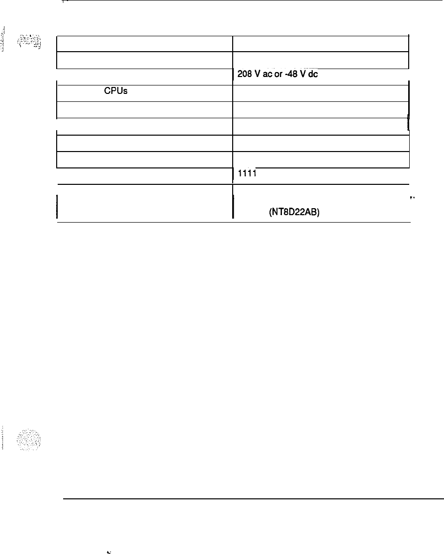
Product description 67
Table 4
_I
System option 61 specifications
‘,j
.<..:.
1
:;.‘.
j
;,:.:;,
2;
:
1
;._,
Power AC or DC
.
. .
(,
Maximum Number of Ports 2000
Input Voltage
1208Vacor-48Vdc
I
Number of CPUs 2
Number of Network Loops 32
Cooling
1
Fan Impellers in pedestal
I
Memory
Storage Media
768K
Floppy Disk Unit or Multi Disk Unit
Software Generic
I1111
Rls 15
I
Hardware Features
I
1
One Network Group, Standard Power
I
I
Distribution Unit and Contains System
.-
Monitor (NT8D22AB)
I
System overview 553-3001-100
‘...
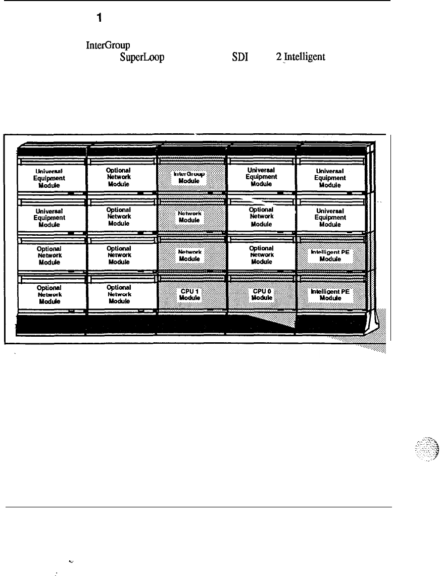
68 Product description
Meridian
1
system option 71
The Meridian 1 system option 71 package includes 2 CPU Modules, 1
InterGroup module, 1 Network Group assembly, 2 Conference and TDS
cards, 1 SuperLoop Network card, 2
SD1
cards, 2.Intelligent Peripheml
Equipment Modules, 2 Pedestal assemblies and 2 Top Caps. The FDU or
MDU assembly must be added. Figure 28 shows a typical configuration
with the shaded areas showing the base package.
Figure 28
System option 71
System overview 553-3001-l 00
C.
:
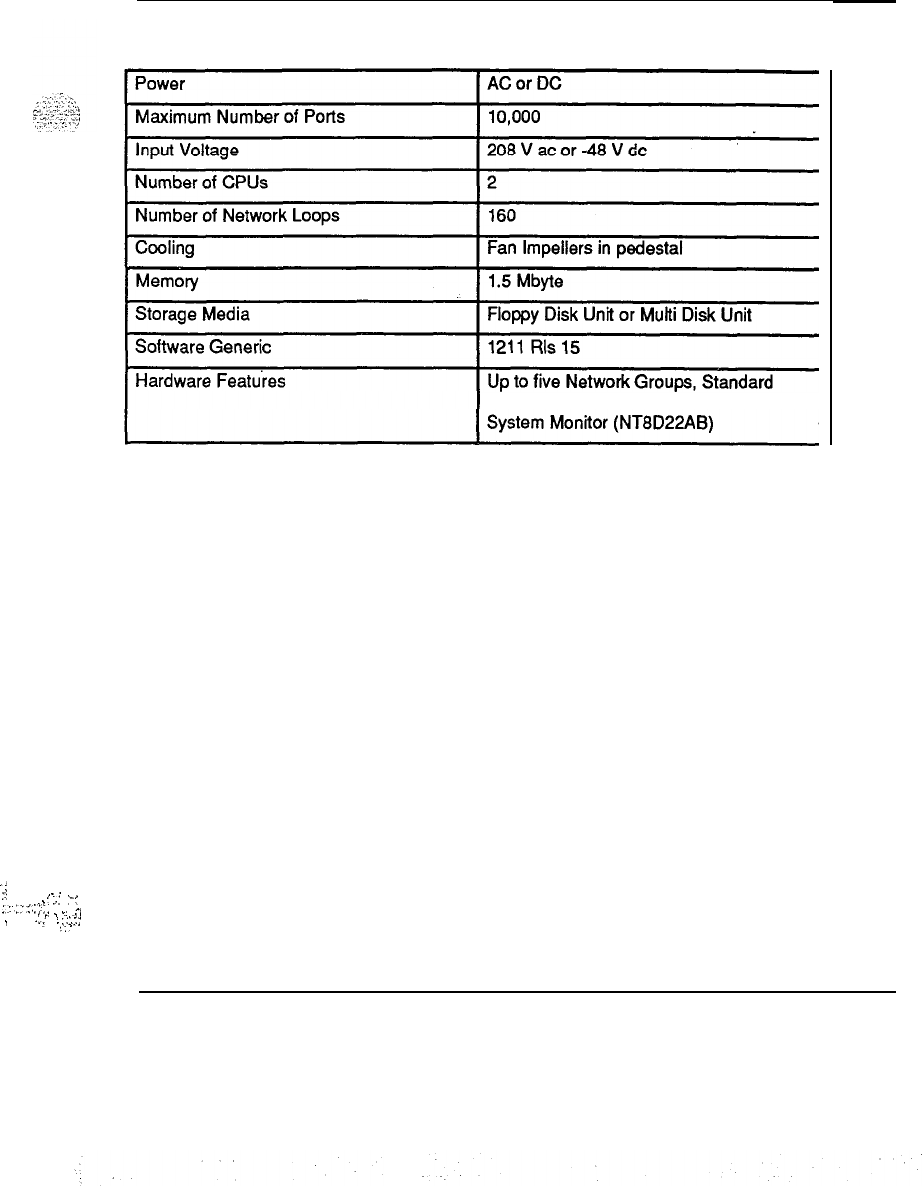
Product description 69
Table 5
System option 71 specifications
Power Distribution Unit and Contains
‘:
:;
..-
.
.
.
: :.:
“C
:::‘:.:‘)
,
_.
.
-.
A,
~
.,.E
:
.:::.::
::.
System overview 553-3001-100

70 Product description
System overview 553-3001-l 00
.
.

71
List
of
terms
ACD
Automatic Call Distribution.
ADM
Add-On Data Module.
AIM
Asynchronous Interface Module.
ALU
Arithmetic Logic Unit.
Architecture
The interrelationship between the parts of a system. The framework of a
system.
ASIM
Analog
Asynchronous/Synchronous Interface Module.
A process which models information in the form of a continuously varying
parameter such as current, voltage, or phase.
System overview 553-3001-100

72 List of terms
Analog signal
ANI
Ampere
Backplane
Battery back-up
BISDN
BTU
Capacity
Cards
Card Cage
A signal that varies in a continuous manner such as voice or music. An
analog signal may be contrasted with a digital signal which represents only
discrete states. The signal put out by a data set has both analog
.zuid
discrete
characteristics.
Automatic Number Identification.
A unit of electrical current or the rate of flow of electricity which is equal to
watts divided by volts.
A printed circuit board that extends throughout the length of the shelf and
connects
to
the circuit pack connectors. Also known as a motherboard.
System power furnished by stand-by batteries that are charged by a charger.
If commercial power fails, the batteries will maintain service for a limited
period of time determined by the size of the batteries and the traffic on the
system.
Basic Rate Integrated Services Digital Network.
British thermal unit. The quantity of heat required to raise the temperature
of one pound of water one degree Fahrenheit at a specified temperature (as
39”
E).
Also means Bus Terminating Unit.
The information-carrying ability of a telecommunications facility, group,
network, or system measured in Bits Per Second.
See circuit packs.
Also referred to as card chassis. A frame for holding circuit cards in a
microprocessor. A standard cage holds nine cards; units with motherboards
can hold up to 20 cards.
System overview 553-3001-l 00
List of terms 73
CAS
Centralized Attendant Service.
CASM
Centralized Attendant Service, Main.
CASR
Centralized Attendant Service, Remote.
cc
Clock Controller.
CDR
Call Detail Recording.
CE
Common Equipment.
Central Office (CO)
The site where the telephone companies terminate customer lines and locate
the switching equipment which interconnects those lines.
Central Processing Unit (CPU)
The main portion of a computer that contains the primary storage,
arithmetic and logic units, and the control unit; Mainframe.
Centralized depot
A repair house for SL-1 systems that serves subdepots.
Centrex
Central Exchange. A telco PBX type of service incorporating Direct Inward
Dialing (DID) and Automatic Identification of Outward Dialed Calls
(AIOD).
Circuit packs
Also known as cards, circuit packs are individual circuit boards that carry
the necessary electronics for particular functions (memory, disk drive
control, etc.
).
These cards lit into expansion slots provided by Apple,
IBM, Radio Shack, and other computer manufacturers.
ClwlA
Changeover and Memory Arbitrator.
System overview
553-3001-100
.
.
74 List of terms
co
Central Office.
CPU
Central Processing Unit.
Common equipment (CE)
A hardware subsystem that houses one or more Central Processing Units
(CPUs), memory circuits, mass storage devices, and service circuits.
Configuration
A group of machines (hardware) which are interconnected and are
programmed to operate as a system.
Data Terminal Equipment (DTE)
Equipment or devices which are capable of transmitting and/or receiving
data signals over a communications network commonly called a business
machine.
.-
dB
Decibel
DCHI
D-Channel Handler Interface.
Diagnostic programs
Software routines used to test equipment and pinpoint faulty components.
Digital
A process which models information as discrete values of some parameter
such as voltage, current, or phase. Compare with analog.
Digital Multiplex Switching System (DMS)
A family of switching systems using new technology that provides digital
circuit switched service for voice and data transmission. DMS is
characterized by the use of pulse code modulation (PCM) and time division
multiplexing (TDM) throughout the switched network. The system allows
the direct switching of PCM signals without their conversion to analog
format.
System overview 553-3001-l 00
.i
,..:‘.(..
..(
.;:,:
,._.
.‘,’
_’
List of terms 75
Digital signal
A signal made up of discrete, non-continuous pulses whose information is
contained in theirduration, periods, and/or amplitude.
Directory number
DSL
DTE
DTI
DTR
EIA
EMI
ESN
Failure rate
Firmware
FM
The four-digit number or extension given to a Meridian SL-1 telephone set.
Also known as DN.
Digital Subscriber Loop.
Data Terminal Equipment.
Digital Trunk Interface.
Digitone Receiver.
Electronics Industry Association.
Electromagnetic Interference. Unwanted electromagnetic coupling.
Examples are ham radio heard on electric organs and church music heard in
hearing aids. Also known as QRM or “static.”
Electronic Switched Network.
The estimated number of failures for that item during one million (106)
hours of operation.
A set of instruction sequences stored permanently in hardware (ROM).
Frequency Modulation; A process whereby the frequency of a previously
single frequency carrier wave is varied in step with the amplitude of a
complex modulating wave. Also means Fully Modular.
System overview 553-3001-100
c
76 List of terms
Frame
A distributing frame. The structure on which all distribution and trunk
cables into a central office are terminated (attached).
Frequency Division Multiplexing (FDM)
Combining two or more information channels into a single transmission
channel by assigning each information channel an exclusive frequency band
within the transmission channel bandwidth. (See “Multiplex” and “Time
Division Multiplex.
“)
I/O
Input/Output; Refers to devices that communicate with customer
quipmcnt
The result equals a properly functioning communications channel or system.
I/O
Channel
Input/Output channel; A component in a computer system controlled by the
central processing unit that handles the transfer of data between main
‘-
storage and peripheral equipment.
I/O
Panel
A separation plane that prohibits RF (Radio Frequency) emissions from
passing through the cube and provides mounting for I/O cable connectors.
ISDN
IVD
Kbk
Line
Loop
MCDS
Integrated Services Digital Network.
Integrated Voice and Data.
Kilobits
per second.
A communications channel or circuit an electrical path.
A bidirectional path between network equipment and peripheral equipment.
Multi-Channel Data System.
System overview
563-3001-100
.
.
List of terms 77
MDF
Main Distributing Frame. See “Frame” above.
‘I
‘I.
::>;..
:::>
MF
.>,
.
,..:.
.,
-“’
..a
-1
u:;.::
t
-.;
>
Multi-Frequency; A method of sending numerical address digits between
telephone company switching centers coded as two or more frequencies
between 300 and 3400 Hertz.
MFS
Multi-Frequency Signaling. Also means Multi-Frequency Sender.
MGS
Multi-Group Switch.
MSI
Mass Storage Interface.
MSL-1
Meridian SL- 1.
MSU
Mass Storage Unit.
Multiplex (MUX)
The process of combining two or more information channels into a single.
.-
transmission channel. (See “Frequency Division Multiplexing” and “Time
Division Multiplexing.
“)
Network equipment (NET)
A hardware subsystem that provides digital multiplexed switching for voice,
data, and signaling paths.
NFT values
The number of spares required for a field-replaceable item. NFT is
calculated by multiplying the number (N) of that item in use by the failure
rate (F) for the item from Appendix 1 by the turnaround time
(T)
in hours.
(N X F X T = NFT value.
)
See Appendix 1 for details.
:
. . . . . .
,.
.
.,
:
:.:.-..1.
:‘I
:
‘“<
._
-I
/
,,
NTP
Northern Telecom Publication.
System overview 553-3001-l 00
..d
:.:

78 List of terms
ODAS
Office data
Office Data Administration System; provides a method of retrieving
administrative information stored in Meridian SL-1 memory.
Office data represents system configuration data, peripheral equipment data,
and transient data (temporary) used for call processing.
PBX
Private Branch Exchange.
PCM
Pulse Code Modulation,
PDU
Power Distribution Unit.
PE
Peripheral Equipment.
Pedestal
Base assembly upon which Universal Equipment Modules are stacked; The
pedestal houses the Power Distribution Module, System Monitor, Blower
Module (and/or Fan assembly), Harnessing, and Air Grille and Filter units.
Peripheral equipment
A hardware subsystem that provides analog and digital telephone and trunk
interfaces and houses a combination of line, trunk, and receiver packs.
Population range
The quantity of each type of SL-1 switch in the area served by a repair-
house depot. See Appendix 1 for details.
Power supplies
Individual units that generate the different DC voltages required by
backplanes installed in a module. Their primary function is to provide
power to a shelf of cards housed within a UEM.
PRA
Primary Rate Access.
System overview 553-3001-100
:

List of terms 79
ISDN Primary Rate Interface.
Private Branch Exchange
PBX; A small telephone switching center enabling a customer’s telephone
stations to connect to the public switched network.
Private Exchange
A private (manual) telephone exchange that provides private telephone
service to an organization that does not allow calls to be transmitted to or
from the public telephone network.
PROPvl
Programmable Read-Only Memory.
Public Switched Network
The Direct Distance Dialing (DDD) telephone network; Any exchange type
of service that is made available for public use.
. .
Pulse Code Modulation (PCM)
A modulation technique whereby the signal is converted from an analog to
digital format by sampling the signal at periodic intervals and digitizing the
amplitude into a finite number of discrete levels; Five-bit information code.
RAM
Random Access Memory; Storage system or computer memory that is
accessible by the user for either storing or retrieving information. RAM is
volatile memory.
Redundancy
The duplication of software/hardware used as a standby in case one fails
(redundant CPUs).
Retrofit
To furnish with new parts or equipment not available at the time of
manufacture.
RF
Radio Frequency; A group of electromagnetic energy waves whose lengths
are between the audio range and the light range.
System overview 553-3001-100

80 List of terms
RFI
RH
ROM
The disruption of radio signal reception caused by any source which
generates radio waves at the same frequency and the same path as the
desired wave.
Relative Humidity.
Read Only Memory: Storage system or computer memory that is “burned
into” the microprocessor chip and can only be read, not written to or
modified. Non-volatile memory.
RPE
Remote Peripheral Equipment.
Satellite operation
SBE
SDI
SEQ
Single depot
Software
The operation of a telecommunications system at a remote location as a‘
completely unattended system connected to the main system by special
point-to-point circuits. The two (or more) systems act as one total system
served by attendants at the main system.
Segmented Bus Extender.
Serial Data Interface.
Sequencer.
A repair house that services SL- 1 systems.
A set of programmed instruction sequences stored either as resident
programs in the system memory or as non-resident programs on disk which
are loaded into memory when needed.
:
.
.I
,
Software generic
i‘.-,-
.,-;9
A term used to describe the software package being used. Each software
generic (X11, for example), has a series of releases (like release 8).
System overview 553-3001-l 00
.
.
. .

List of terms 81
Spare stock size
The quantity of spares for a given stock item.
Sparing interval
The period of time that stocks of replaceable SL-1 items should last without
being replenished.
Stock confidence level
The allowed probability of not being out of stock when the sparing interval
of one year is greater than 99. 9 percent.
System hardware
Hardware configuration.
System monitor
A microprocessor-based circuit pack used to monitor the UEM (Universal
Equipment Module) power supplies, stack thermal status, and fan operation
status. Each system monitor reports its status to the system CPU, and the
head (master) system monitor checks their statuses. The master system
monitor will trip the stack circuit breaker in the event of a problem
(excessive temperature, for example).
TCM
Time Compression Multiplexing.
TDS
Tone and Digit Switch.
Time Division Multiplex (TDM)
Combining two or more information channels into a single transmission
channel by assigning each information channel an exclusive periodic
transmission time interval. (See “Multiplex: and “Frequency Division
Multiplex.
“)
Top cap
A drip-proof cover for the UEM (Universal Equipment Module). It
provides airflow exits, RF/EM1 shielding, I/O cable entries/exits, and
overhead cable-rack mounting.
^....
;.
:
. .
.
.‘!
;
.;,.:
,‘j
3PE
._
..,
v
Three-Port Extender.
System overview 553-3001-100
Y

82
List of terms
Trunk
A single circuit between two points, both of which are switching centers or
individual distribution points.
Teletype machine.
2DFi
Two-Way Tie, Dial Repeating.
Turnaround time
The number of days it takes to replace a failed item and to return a useable
item to stock.
UEM
Universal Equipment Module; a modular, self-contained hardware cabinet
(or cube) that houses a card cage assembly, its associated circuit packs,
power supplies, and I/O panels. A Meridian SL-1 system may consist of
stacks of UEMs.
UPS
Uninterrupted Power Supply.
VAC
Voltage
Alternating Current.
VDC
Voltage Direct Current.
VDT
Video Display Terminal; monitor.
System overview 553-3001-100


SL-1
System options
21,51,61,71
System overview
Copyright
0
1990 Northern
T&corn
All rights reserved.
information subject to change without notice.
Release 1
.O
Standard
January 29, 1990
Printed in U.S.A.
nit
northern
tolocom
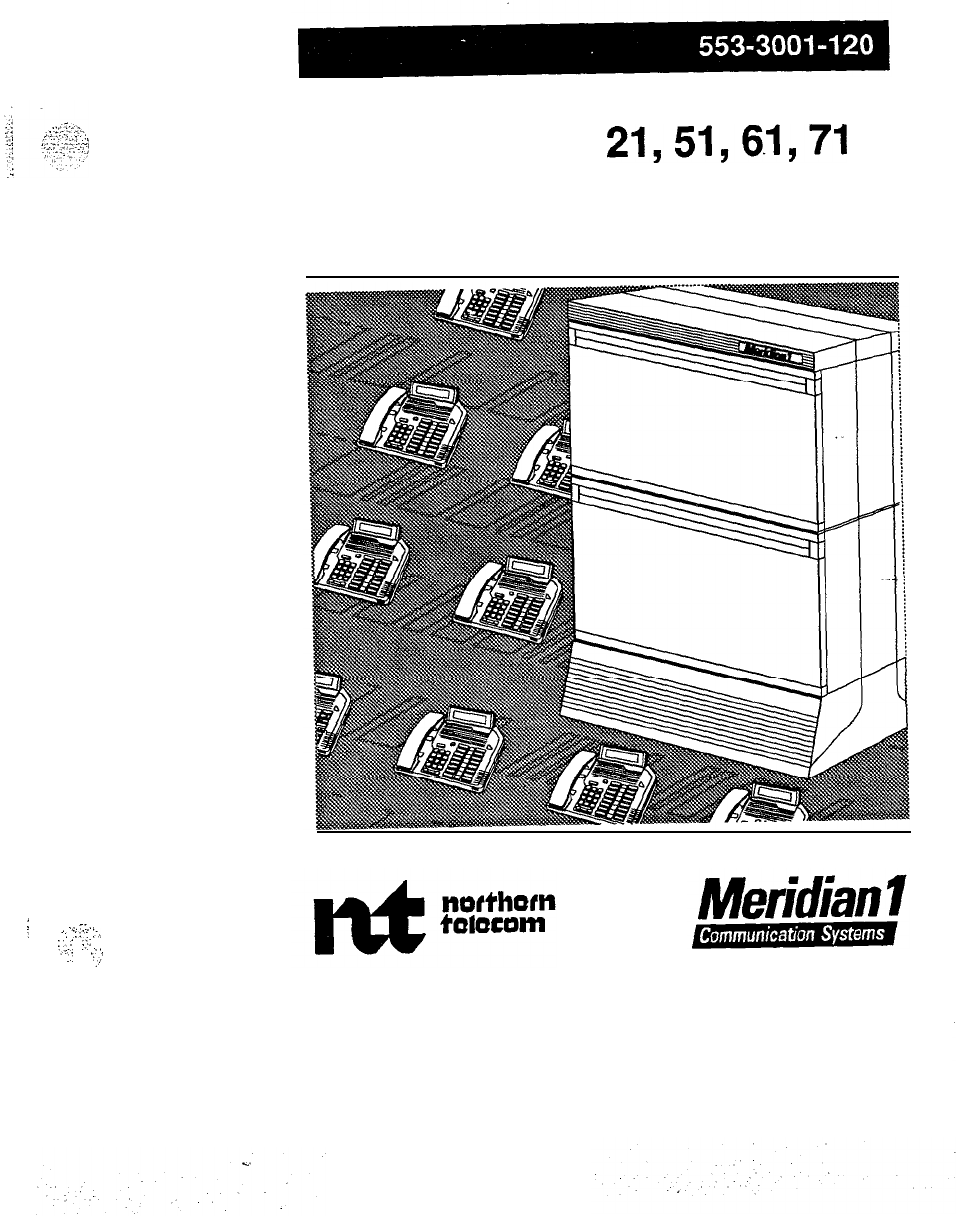
SL-1
System options 21,51,6.1,71
Installation planning
Standard
:
;.,..
-...
.
‘.
.::.
:-/
:,“.:
i;.:
:’
:
.,I’

-3
:
:..
““..
,i
i.’
d
:
!
S-1
System options
21,51,61,71
Installation planning
Publication number: 553-3001-l 20
Document release: 1 .O
Document status: Standard
Date: January
29,199O
0
1990 Northern Telecom
All rights reserved.
installation planning 553-3001-120

ii
Revision history
January 29,199O
Standard, release 1.0
Installation planning 553-3001-120
.
.
,

Preface
iii
Notice
The Canadian Department of Communications label identifies certified
equipment. This certification means that the equipment meets certain
telecommunications network protective, operational and safety
requirements. The Department does not guarantee the equipment will
operate to the user’s satisfaction.
Before installing this equipment, users should ensure that it is permissible to
be connected to the facilities of the local telecommunications company.
The equipment must also be installed using an acceptable method of
connection. In some cases, the company’s inside wiring associated with a
single line individual service may be extended by means of a certified
._
connector assembly (telephone extension cord). The customer should be
aware that compliance with the above conditions may not prevent
degradation of service in some situations.
Repairs to certified equipment should be made by an authorized Canadian
maintenance facility designated by the supplier. Any repairs or alterations
made by the user to this equipment, or equipment malfunctions, may give
the telecommunications company cause to request the user to disconnect the
equipment.
.-
:
:..
11
;,
.;
(.
.;.,
.:
.
. . .
,,..
.
. .
.
. . .
..I
.,
-,.
. . .
.
.,
.;
Installation planning 553-3001-l 20
I
.
iv Preface
J
Users should ensure for their own protectjon that the electrical ground
connections of the power utility, telephone lines and internal metallic water
pipe system, if present, are connected together. This precaution may be
particularly important in rural areas.
CAUTION
Proper electrical ground connections
Users should not attempt to make electrical ground
connections themselves, but should contact the
appropriate electrical inspection authority, or
electrician, as appropriate.
Installation planning 553-3001-120
c
About this document
This section of the Planning and engineering guide deals with planning the
environment that the SL-1 (Option
21,51,61,
and 71) system will inhabit,
including equipment location, commercial power requirements (AC and
DC), grounding, and cabling requirements. Most of the considerations for
site planning and installation are common for both AC- and DC-powered
systems. Where there are differences, these are noted in the applicable
sections. The information is intended to assist with the site selection, site
planning, and installation planning process.
References
See the SL-1 planning
&
engineering guide
for
-
Muster index
(553-3001-000)
-
System overview (553-3001-100)
-
Installation planning
(553-3001-120)
-
System engineering
(553-3001-151)
-
Power engineering
(553-3001-152)
-
Sparesplanning
(553-3001-153)
-
Equipment identification and ordering
(553-3001-154)
See the list of line and trunk circuit descriptions in the
Muster index
(553-3001-000) for specific references to lines and trunks.
See the SL-1 installation and maintenance guide
for
-
System installation procedures
(553-3001-210)
-
Circuit pack installation and testing
(553-3001-211)
Installation planning 553-3001-120
.d

vi About this document
-
Installation procedures for telephone
sets and attendant consoles
(553-2201-215)
-
Extended systems installation
(553-3001-250)
-
Disk drive upgrade procedures
(553-3001-251)
-
General maintenance information
(553-3001-500)
-
Fat.&
clearing (553-3001-510)
-
Hardware replacement
(553-3001-520)
See the SL-I XII software guide
for an overview of software architecture,
procedures for software installation and management, and a detailed
description of all Xl 1 features and services. This information is contained
in two documents:
-
XII software management
(553-3001-300)
-
Xl1
features and services (553-3001-305)
See the SL-1 XII input/output guide
(553-300140) for a description of all
administration programs, maintenance programs, and system messages.
Installation planning
X3-3001
-120
.
.
About this document vii
Related documentatiori
The following documents contain information that may be of value during
the site planning and preparation process.
-
1987. “Maintenance, Testing and Replacement of Large Storage
Batteries.” IEEE, Vol. 450: all pages.
-
-
1987. “Design and Installation of Large Lead Storage Batteries.” IEEE,
Vol. 484: all pages.
-
1981,1982,1983. ANSI/IEEE Standard, Vols.
484,142,81:
all pages.
(484-1981; 142-1982; 81-1983)
-
1984. Gaseous Hydrogen Systems.
NBRA,
Vol. 50A: all pages.
-
1984. National Electrical Code. NFPA, Vol.. 70: all pages.
-
1986. Canadian Electrical Code. Canadian Standards Association,
C22-1-1986
-
Grounding Electrode System
. .
(NBC Articles: 250-23,250-26,250-54,250-8 1,250-83,250-84 and,
250-86)
(CEC
lo-204,10-206,10-504,10-520,10-700-710)
-
Grounding Electrode Conductor
(NEC
Articles:
250-23,250-26,250-51,250-53,250-g
1,250-92
and,
250-94)
(CEC 10-500,
lo-502,10-804,10-808,10-812)
Installation planning
553-3001-l 20
viii About this document
-
Grounded Conductor (i.e., Neutral)
(NEC Articles: 250-26,250-50,250-51,250-53 and, 250-61)
(CEC
lo-206,10-900-908,10-500,10-502,10-518)
-
Equipment Grounding Conductor (NEC Articles: 250-50,250-5 1,
250-53,250-57,250-91,250-32,250-92
and; 250-95)
(CEC
10-900-908,10-500,10-502,10-510,10-804,10-300,10-302)
-
Main Bonding Jumper (NJX Articles: 250-23,250-26 and, 250-61)
(CEC
lo-204,10-206,10-518,10-520)
-
Grounding Evaluation-Practices and Equipment, ECOS Electronics
Corporation, 205 West Harrison Street, Oak Park, IL 60304
-
Full of Potential. James G Biddle Co. Plymouth Meeting, PA 19462.
-
Protection of Electronic Computer/Data Processing Equipment
XFPA
75
-
MIL-Handbook
-
4 19 (raised floor installation requirements)
-
“Network Equipment Building Systems Generic Equipment
Requirements” specification TR-EOP-000063. Bellcore.
-
OSHA
-
Occupational Safety and Health Administration Standards (29
CFR 1910)
-
Recommended Practice on Static Electricity
-
NFPA 77
-
Soares Grounding Electrical Distribution Systems for
Safety
-
Uniform Building Code 1982
-
Local building codes
Note:
If a conflict arises between a code included in this document
and a local or national code, follow the local or national code.
Installation planning 553-3001-120
.
.

ix
Contents
Planning activities
1
The installation outline
1
The Milestone chart 4
Researching the requirements
General requirements
The equipment room environment
Environmental factors
Temperature and humidity
Static electrfcity
Vibration
Electromagnetic Interference (EMI)
Dust
Lighting
Earthquake bracing
Structural
Air conditioning requirements
SL-1 system power options
DC-powered SL-1 systems
AC-powered SL-1 systems
Commercial AC power source
Input power specifications
Commercial power conditioning
Grounding
Commercial power and grounding requirements
Building ground requirements
Isolated ground topology
Non-isolated ground topology
Grounding guidelines
7
7
8
11
11
11
11
..-12
12
13
13
13
13
16
17
18
18
19
20
20
21
21
22
22
22
Installation planning 553-3001-l 20

x Contents
AC service panel
-
Dedicated versus shared power
Auxiliary power requirements
Isolated service receptacles
Non-isolated service receptacles
Power Fail Transfer Unit (PFTU) powering
Cabling
Cable types
Twisted-pair telephone cables
25-Pair MDF cables
Twisted-pair shielded cables
Interface (l/O) cables
UEM cable routing
Network to PE cabling
Power and ground cables
Cable access requirements
Fire protection and safety precautions
Fire protection and prevention
Recommended fire extinguishing systems
Security precautions and safeguards
Safety procedures and training
Occupational noise exposure
23
23
32
32
..c
32
4
:‘I.
3
+.
:. .
.._
:y
.::
“‘:
.
>
%
32
”
33
33
33
33
33
34
34
34
34
35
35
‘-35
36
37
37
37
Planning the site
Selecting a site
Space
Location
Power and grounding
Structural integrity
Developing the site
The equipment room
Primary storage
Secondary storage
Maintenance/Technician area
Equipment room accessories
The floor plan
Floor loading estimates
The building cable plan
Wire routing
Floors
39 ---
39
39
39
39
39
40
40
40
41
41
41
42
47
.+:?tT.
48
51 c;;
-$
51
Installation planning 553-3001-120
.
.

Contents xi
Ceilings
-
51
Walls
5-l
Between floors
51
Electromagnetic Interference
(EMI)
52
Termination points
52
Distribution frames
52
Preparing for delivery
Considerations
Equipment handling precautions
55
55
57
:.
-I--
_
_‘.
.c..:.
__
:;-f
._,,
::..-
:;
:’
\,.‘“..,..“,
.,
-‘.
_,
Preparing for installation
Work orders
Equipment room floor plans
Cabling plan
The installation plan
Manuals
Preinstallation inspections
Equipment room inspections
General inspections
Reserve power inspections
59
59
60
61
62
62
62
63
64
64
Installation planning
553-3001-120

xii Contents
Installation planning 553-3001-120
.d
,

1
Planning activities
The installation outline
Since installations differ from site to site, no single overall schedule of
predelivery activity will apply in all cases. In each instance, prepare a
detailed plan when the site has been selected and the equipment ordered.
Use Table 1, “Outline for installation planning,
”
as a guide for making a
detailed checklist. Use Table 2 for listing the activities that are involved in
site preparation.
.
.
.
,‘{;,‘,y
::
Installation planning 553-3001-l 20
..s

2 Planning activities
_’
Table 1
Outline for installation planning
Items
Research
Procedures
Read the requirements identified
in this document.
Establish equipment environment,
air conditioning requirements,
floor loading requirements, and
other requirements listed in this
section.
Select a site
Check space, location, power and
grounding, and delivery issues.
Develop the site
Produce a detailed checklist. Use
this outline as a guide.
Prepare for delivery
Prepare equipment room
environment and delivery route.
Ensure safety conditions.
Establish fire prevention.
Prepare for installation
Obtain work orders, equipment
room floor plans, cabling plans,
manuals, installation plans,
preinstallation inspections, and
delivery equipment.
Installation planning 5!53-3001-120
Planning activities 3
.
._
.
.
. .
i
.
Table 2
Site planning activities
Activities
Wform
detailed site survey. Determine if building wire needs
/erification and gather preliminary customer data.
Hold
contract review meeting.
Prepare project plarl.
Hold customer meeting to discuss project plan and division of
responsibilities.
Hold Construction
Phase site survey to prioriiize site development
tasks.
.
Identify environmental, space, power and grounding requirements ant
prepare site accordingly.
Gather customer data.
Perform site inspections to ensure site is ready for installation.
Plan customer user training.
Note: In all the activities above, the Northern Telecom distributor is
generally responsible to ensure that these activities have been
implemented.
Installation planning 553-3001-l 20
.
.

4 Planning activities
-
The Milestone chart
Planning and monitoring site preparation activites is easier when you use a
Milestone chart. The Milestone chart is a site planning schedule. It shows
the sequence of activities necessary to complete a job and will be different
with each site. Depending on the complexity of the site, the chart may be
more detailed with scheduled due dates for each activity group.
When preparing your Milestone chart, consider not only the individual
operations, but the overall installation schedule. A Milestone chart may
show the necessary operations in order and may assign a start date and end
date for each.
Remember to obtain the appropriate sign-offs when the site is ready for
delivery and installation of the equipment. Sign-offs may include
regulatory items such as electrical and air conditioning inspections and the
approval of the cable plan.
Table 3 lists typical activities that should be included in the Milestone chart.
Your chart may differ from this one.
The first Milestone prior to delivery should be used to prepare specifications
and drawings, request bids, order equipment related to the site preparation,
and begin renovations or construction of the equipment room.
Installation planning 553-3001-120
Planning activities 5
Table 3
Milestone chart
I
Select the site.
Plan the equipment room layout.
Plan power and grounding, reserve and/or
battery requirements.
Plan cable requirements.
Plan and start renovations to implement
equipment room layout.
Continue site construction and renovation
tasks.
Install power, grounding, reserve power, air
conditioning, and heating.
Install special rigging such as overhead cable
racks and distribution frame equipment as
required.
3
Test site wiring to ensure minimum
requirements are met.
Complete construction and ensure power and
grounding are in place.
Test air conditioning and heating systems.
Complete final equipment room inspection
identifying and resolving any delivery
constraints.
Make equipment delivery arrangements.
Note: The Milestone chart shown is only an example of the activities
ecommended for site preparation. Depending on the complexity of the site, the
zhart will be more detailed with scheduled due dates (milestones) for each
33ivity group.
Installation planning 553-3001-120
2,

6 Planning activities
Installation planning 553-3001-120

7
Researching the requirements
Knowing the requirements for system installation saves valuable time and
energy when the time comes for system delivery. The first step in planning
a site, then, is researching those requirements. The purpose of this section
is to define the general requirements necessary to plan and develop the site
before system installation.
General requirements
The following general requirements must be considered (in addition to local
and national building and electrical codes) when planning the installation of
an SL-1 system:
-
Equipment room environment (including preliminary floor plan and
system layout)
-
Power and grounding requirements
-
Cabling requirements (including guidelines for ordering correct cable
lengths)
-
Fire protection (including location of sprinkler heads) and safety
precautions
Installation planning 553-3001-120
<I
..:-
-...
8 Researching the requirements
The equipment room environment
The environment that the SL-1 operates in and that spare parts are stored in
can influence system performance and reliability. When establishing the
equipment environment, control over these factors is necessary:
-
temperature and humidity
-
static electricity
-
vibration
-
electromagnetic/radio frequency interference
-
dust
-
lighting
-
floor/walls/ceiling materials
Note: The location must provide sufficient cooling for efficient
operation of the equipment and a suitable operating environment for
the system.
q
CAUTION
I
Heat sources near equipment
.
Equipment exposure to absolute limits should not
exceed 72 hours. Since temperature readings are taken
at the front of the equipment and above the floor, no
heat sources (such as floor heaters) should be placed
near the equipment.
Installation planning 553-3001-120
_.
.
2::
:-..Y
__
.,
“.
‘I-‘1
*,:.y;.
.,
‘.:
.,.
C.
:
.
.
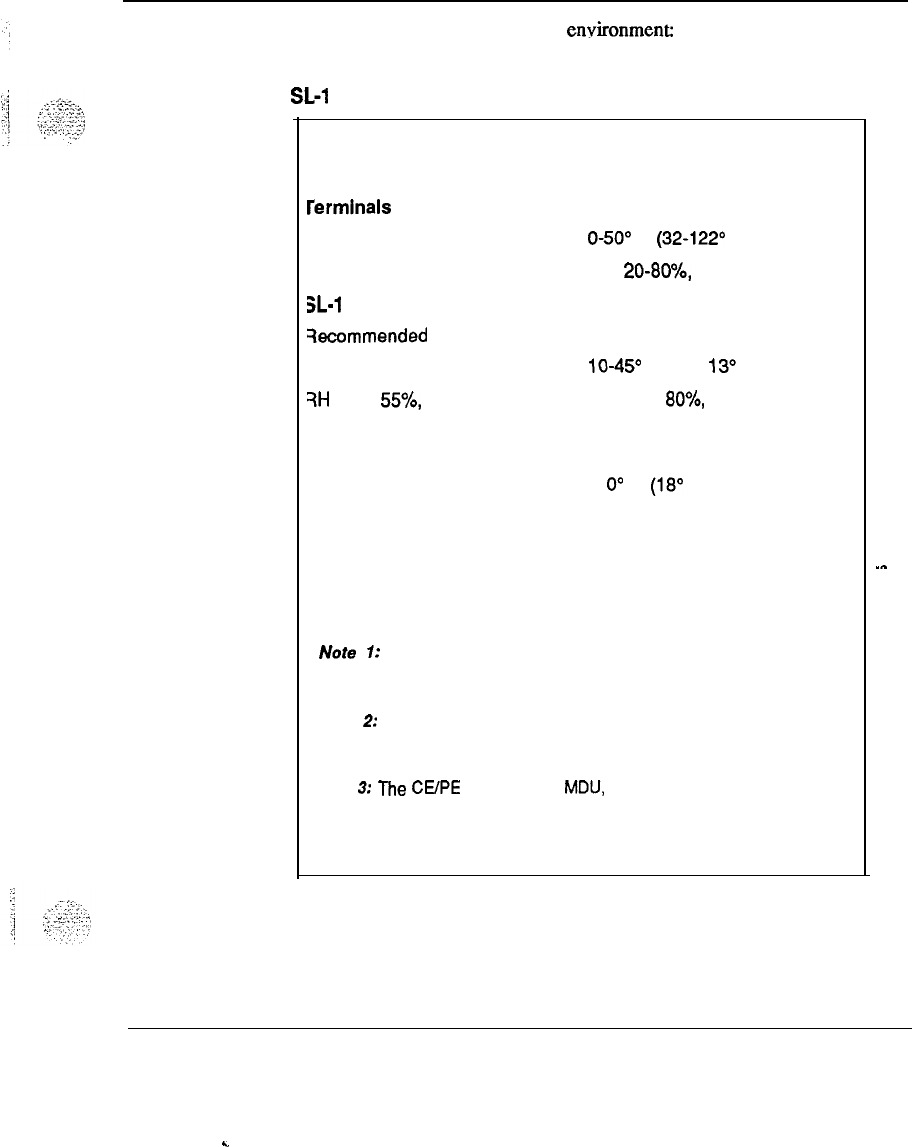
Researching the requirements 9
Table 4 shows the SC-1 operating en?rironment
Table 4
SL-1 operating environment
Equipment
rerminals (sets)
3L-1
Gccmmended
15-30” C (59-86” F)
?H
20 to
55%,
Ion-condensing
Temperature and humidity
considerations
Absolute
O-50’ C (32-122O F),
RH 20-80%, non-condensing
Absolute
lo-45O
C (50-l
13O
F)
RH 20 to
80%,
non-condensing
temperature change less than
1
O”
C (18” F) per hour
Auxiliary (terminals and
Refer to specific NTP document
printers, for example)
or manufacturer’s guidelines.
Note 1: Temperature readings should be taken 30 inches (760mm) from
the front of the system.
Note
2:
Frequent and extended operation above the recommended
temperature limits may degrade system reliability.
Note 3: The CVPE power supply, MDU, and FDU units must be located in
the lower two module positions when the system is operated above the
recommended temperature limits.
.-
Installation planning 553-3001-l 20
.
.
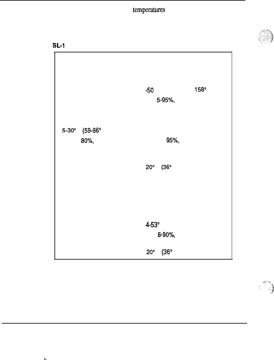
10 Researching the requirements
In addition to proper operating
temperaturq
and humidity considerations,
the SL-1 should be stored and/or transported under the following
specifications:
Table 5
SL-1 storage/transportation environment
Equipment
Terminals (sets)
SL-1
Recommended
1 5-30°
C (59-86” F)
RH 20 to
80%,
non-condensing
Temperature and humidity
considerations
Absolute
-50
to 70” C (-58 to
158O
F)
RH 5-95%, non-condensing
Absolute
-20 to 60” C (-4 to 140” F)
RH 5 to
95%,
non-condensing
temperature change less than
20”
C
(36O
F) per hour
Auxiliary
Refer to appropriate Northern
Telecom Publication
Floppy diskettes
Absolute
4-53O
C (39-i 27”
F)
RH 8-90%, non-condensing
temperature change less than
20”
C
(36”
F) per hour
installation planning 553-3001-l 20
c.
^.
.
.
.
;
:
::5,
-,
.?

Researching the requirements
11
Environmental factors
Temperature and humidity
High temperatures tend to increase the rate of deterioration of most
materials. Temperature fluctuations can cause temporary or permanent
changes to equipment which can affect the grade of service. Low humidity
conditions can increase the build up of static electricity, while high
humidity can have an adverse effect on the performance of disks, tapes, and
printers.
Static electricity
Microelectronic circuits are extremely sensitive to static discharge. Static
discharge can cause permanent damage to any circuitry and/or interruptions
in system operation and the loss of data. Static electricity could be the
result of physical vibration, friction, and separation of materials. The most
common collectors of static electricity are people.. Other common causes of
static electricity build-up are low humidity, certain types of carpeting, the
use of wax on equipment room floors, and plastic-soled shoes.
Plastic-soled shoes, for example, are noted for generating large amounts of
static electricity. The insulative nature of the shoes, and certain flooring
materials and levels of humidity, can cause the wearer to accumulate and
carry body charges in excess of 15 kV.
Note:
IEEE Standard 142-1982 recommends that flooring resistance
should be more than 25,000
Sz
and less than 1 million megohms,
measured by two electrodes 3 feet (0.91 m) apart on the floor. Each
electrode must weigh
5
lb (2.2 kg) and have a dry flat contact area of
2.5 inches (63.5 mm) in diameter.
Some products that prevent static discharge include sprays, anti-static mats,
and wrist straps.
Vibration
Vibration can cause slow deterioration of mechanical parts and, where
severe, can cause serious disk errors. Structure-borne vibration and
consequent noise transferred to the equipment room should be avoided.
Raised floors should have extra support jacks at strategic places to prevent
the transmission of vibration.
Installation planning 553-3001-l 20
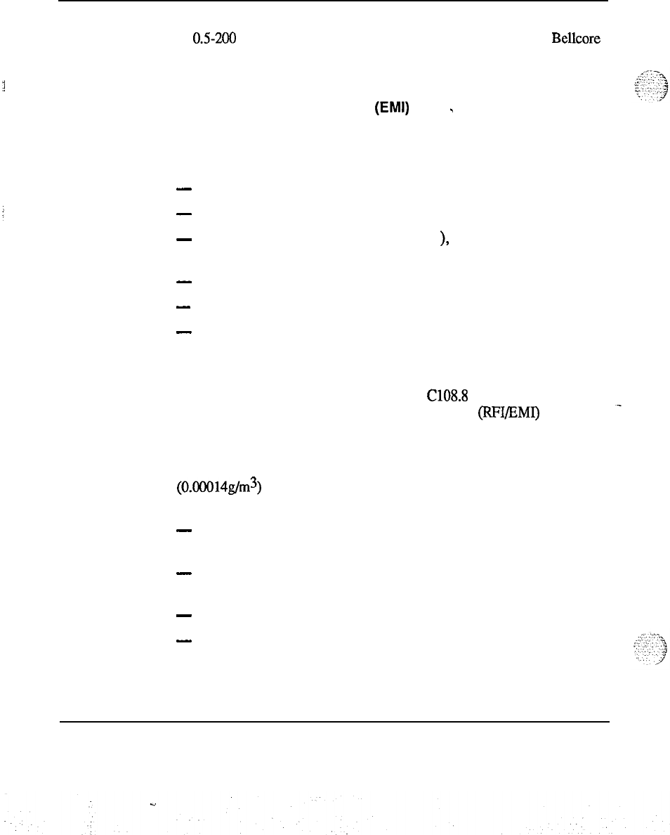
12 Researching the requirements
Vibration in the office environment should be limited to a frequency range
of
0.5200
Hz and a G-force magnitude of 0.1 G (according to the
Bellcore
Network Equipment Building Systems Generic Equipment Requirements
specification TR-EOP-000063).
Electromagnetic Interference
(EMI)
-
Sources of EM1 located close to the equipment may have an effect on
system operation. Common EM1 sources known to disturb system
operation are:
-
thunderstorms, static electricity, high-voltage power lines
-
radar, broadcast stations, mobile communications
-
power tools, appliances (vacuum cleaners
),
and office business
machines (copiers)
-
industrial machines and ultrasonic cleaners
-
vehicle ignition, arc welders, and dielectric heaters
-
dimmer switches
Note:
The SL- 1 system meets the United States Federal
Communications Commission (FCC) Rules, Part 15, Subpart J and
Canadian Standards Association (CSA) C108.8 for radio frequency
interference and/or electromagnetic interference (RFI/EMI) radiation.
Dust
Average dust density for an office environment must be Zone 4
(0.00014g/m3) or better. False ceilings and tiled floors help maintain dust
density requirements. Accumulation of dust and dirt can:
-
scratch gold contacts on printed circuit packs, causing intermittent
failures
-
have conductive contents, increasing component susceptibility to
damage by static electricity
-
cause components to operate at higher temperatures
-
be detrimental to system reliability and performance and increase
maintenance and warranty costs
Installation planning 553-3001-120
Researching the requirements 13
Lighting
-
Lighting illumination of 50-75 footcandles measured 30 inches (76 cm)
above the equipment room floor is recommended. Lighting must not be
powered from the equipment room power panel. For large system
installations, provisions for emergency lighting in the equipment room
should be considered. Direct sunlight in the equipment room should be
avoided to prevent the malfunctioning of devices which employ light
sensors (magnetic tape and disk units).
Earthquake bracing
In some equipment room environments, the need for earthquake bracing
should be considered or may be required. See the
System installation
procedures
(553-3001-210) for detailed instructions on how to install
proper earthquake bracing.
Structural
Floors should either be sealed concrete, vinyl, or mastic tile and should
meet floor loading requirements: avoid using sprayed ceilings or walls.
Air conditioning requirements
The air conditioning provided must be capable of handling
the heat
produced by the SL-1 system, as well as the additional heat produced by
equipment room personnel, lighting, and the heat input of external walls,
windows,
flmrs
and ceilings enclosing the room. A stable ambient
operating temperature of approximately 22’ C (72” F) is generally
recommended. The temperature differential in the equipment room should
not exceed k3.0’ C
(&
5’ F).
Note:
For systems using reserve power batteries, consult the
manufacturer’s specifications for recommended operating temperatures.
Heat dissipation of a system is estimated in BTU/l-u. The amount of air
conditioning required can be estimated at a rate of one U.S. ton of
refrigeration for every 12,000 BTU/hr of heat generated by the equipment
and equipment room personnel, plus one ton for each 500 square feet of
floor space. Each person in the equipment room generates 600 BTU/hr.
Installation planning 553-3001-120
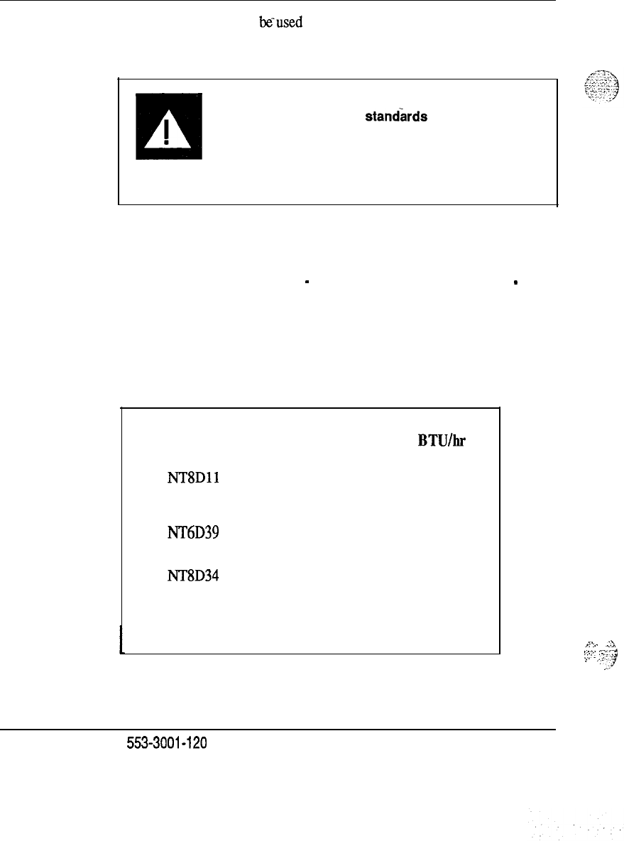
14
Researching the requirements
These guidelines should
beused
along with the following tables when
estimating air conditioning requirements. Exact requirements should be
determined by a qualified air conditioning engineer.
El
CAUTION
I
Proper air conditioning
standkds
.
Digital systems require constant power regardless of
the level of system activity (idle or busy) and therefore
generate heat continuously. Ensure that proper air
conditioning standards are met at all times.
Table 6 shows the maximum power dissipation in the form of heat for each
SL-1 Module. These figures apply to both AC- and DC-powered systems.
The power figures listed here do not necessarily correspond to total input
power, since some of the power
-
especially for peripheral equipment
-
is
distributed out to the sets and is not dissipated within the system.
Table 7 shows the maximum heat dissipation for some of the external DC
power equipment supplied by Northern Telecom.
Table 6
SL-1 system heat dissipation
Heat dissipation
Module Watts
BTU/hr
NTSDll
450 1530
Common/Peripheral
Equipment
NT6D39 400 1360
CPU/Network
NT8D34
300 1020
CPU
-continued-
.._
,.
..-
A
‘_‘-.
“.‘.X
.,
.:
.
.
.3.,
’
‘:--’
.
..y
Installation planning
553-3001-120
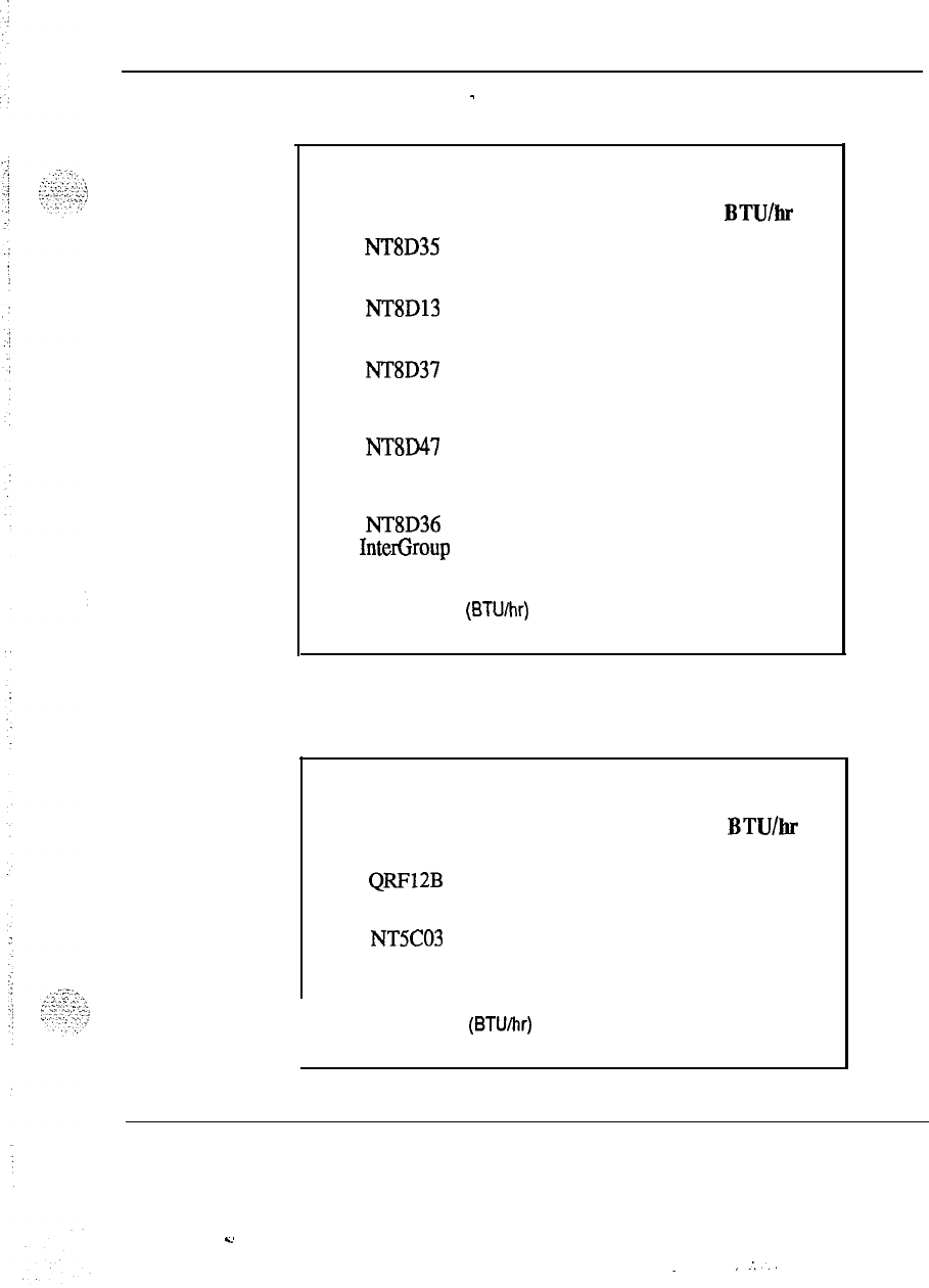
Researching the requirements
15
Table 6 continued
-
SL-1 system heat dissipation
Module
Heat dissipation
Watts
BTU/hr
NT8D35
Network 300 1020
NTSD13
Peripheral Equipment 300 1020
NT8D37
Intelligent Peripheral
Equipment
NTsD47
Remote Peripheral
Equipment
NT8D36
InterGroup
425 1450
300 1020
0 0
Note: Thermal load (BTUIhr) = Total power dissipation (Watts) x 3.4
Table 7
External power equipment heat dissipation
Equipment
QRFl2B
30A Rectifier
NT5C03
50A Rectifier
Heat dissipation
Watts
BTUh
200 680
290 990
I
Note: Thermal load (BTUihr) = Total power dissipation (Watts) x 3.4
Installation planning 553-3001-l 20
..d
.
. .
;..

16 Researching the requirements
Sk-l system power options
-
The SL-1 system is available in both AC and DC versions where DC power
is connected to the commercial power panel by means of extended power
rectifiers or power plants, and the AC power is connected directly to the
commercial power panel. If an Uninterruptable Power Supply (UPS) is
used in conjunction with the AC SL-1 system, the UPS connects to the
commercial AC source and the SL-1 system columns are connected to the
UPS. The SL-1 is available with the following power options:
-
DC-powered systems
-
DC power with reserve power (backup)
-
AC-powered systems
-
AC power with reserve power (backup)
For AC-powered SL-1 systems each column of equipment should have an
AC receptacle provided within 10 feet of the column’s pedestal. If the
system is equipped with a UPS, the AC source should feed to the location of
the UPS (see the UPS vendor’s specifications). The UPS will then feed the
equipment columns.
For DC-powered SL-1 systems the commercial source feeds to a centralized
rectifier rack or to a centralized power plant. The rectifier rack/power plant
._
provides -48 V dc to the system.
In either case the power connections to the SL- 1 system can be provided
through the floor or by means of overhead racks.
Installation planning 553-3001-120
.
.
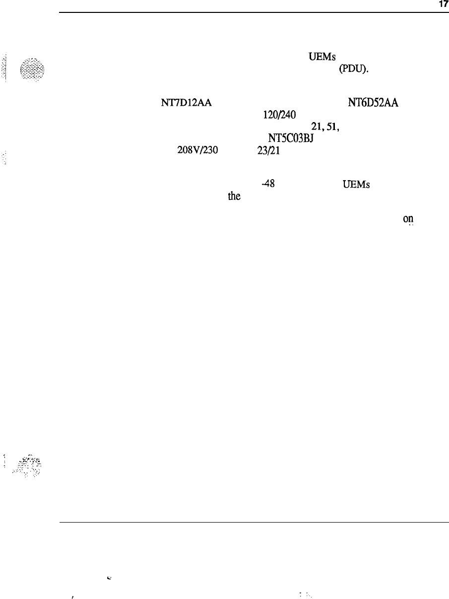
Researching the requirements 17
DC-powered SL-1 systems
DC-powered SL-1 systems, which use direct current UEM power
converters, operate at a nominal -48V dc. URMs in a column are fed DC
power from the pedestal Power Distribution Unit (PDU). The pedestal is
powered from an external DC power plant
The NT7D12AA rectifier rack contains up to three NT6D52AA recitifers
which operate from a nominal 120/240 V ac at 30 Amps. This
configuration is typically used for Options
21,51,
and 61. The QCA13
power plant contains up to four NTSC03BJ rectifiers which operate from a
nominal 208V/230 V ac at 23/21 Amps. This configuration is typically
used for Option 71.
A typical column operating at
48
V dc using four
UEMs
will draw up to 60
Amps depending on the configuration.
Commercial power requirements for the DC power plant depend ou the
system size and power plant configuration. All SL-1 systems can be
powered by customer-supplied or Northern Telecom-supplied -48 V dc.
Refer to
Power engineering
(553-3001-152).
Reserve Power-DC-powered systems that require reserve power use
battery backup. For battery requirements, refer to
Power engineering
(553-3001-152).
---
:
.-.3..
.
-
-.
,..
;
--..
.
.._
,..+zr
f
r-.
:
,_I--
:....
-:t
..-j
Installation planning 553-3001-l 20
.s
,:
..
18 Researching the requirements
AC-powered SL-1 systems-
Power converters in SL-1 systems, which use alternating current, operate at
a nominal 208/240 V ac. A typical system operating from 208 V using four
UEMs
will draw 15-25 Amps depending on the configuration. These are
fed from a central point in the pedestal; access to these connections is
provided and should be used to confirm that the
Ihe
voltage is within the
required range.
Reserve power-AC-powered systems with reserve power use an
Uninterruptable Power Supply (UPS). The UPS must be installed according
to the vendor’s specifications. The UPS installation should be inspected
and signed off prior to starting the SL-1 system installation.
Commercial AC power source
Although some smaller DC systems may use rectifiers that can be
configured for 120 volts, Northern Telecom recommends that all systems
use single-phase 240 volt or 208 volt single phase which is
208Y
derived:
Installation planning 553-3001-120
.4
:..
‘.
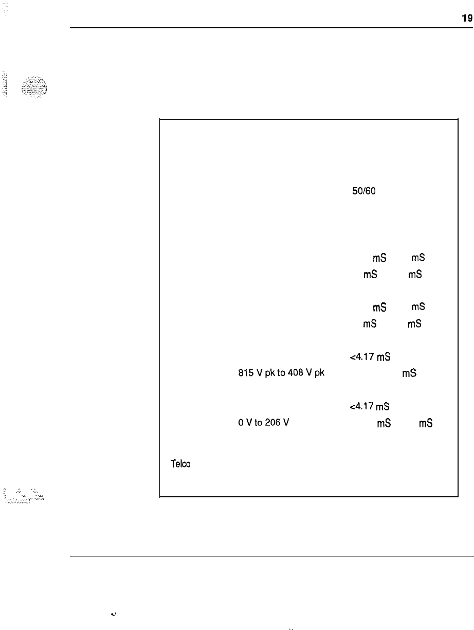
2
.f..
‘>:.
:
r...:.:--:3
‘:.‘...-.I:
Researching the requirements 19
Input power specifications
The following tables provide input system power specifications as required
for
AC
power:
Table 8
Input power specifications
Input Minimum Nominal Maximum
Voltage (VAC) at pedestal 180 2081240 250
Frequency
(Hz) 47
50160
63
Transient tolerance (See note)
Amplitude Duration
. .
Surges
288
V ac
8.34
mS
to 50
mS
276
V ac
50
mS
to 500
mS
Sags
146Vac 8.34
mS
to 50
mS
166Vac
50
mS
to 500
mS
-.
Spikes 815 V pk ~4.17
mS
815Vpkto408Vpk
4.17 to 8.3
mS
Notches
to ov
<4.17
mS
OVto206V
4.17
mS
to 8.3
mS
Note: These values are taken from the National Electric Code and various
Telco specifications. All transients are applied at the peak of the AC
waveform.
Installation planning 553-3001-120
.”
.:

20 Researching the requirements
Commercial power conditi6ning
If the quality of the commercial power source continuously meets the SL-1
system requirements listed in this section, a power conditioner is not
required, however, where the commercial power is of poor quality and
cannot consistently meet the SL-1 system requirements, a powerconditioner
k$?j
L;
:
.cT;.:.x-<
may provide some improvement.
Note:
When using power conditioning equipment, simply install the
equipment in series with the commercial power feed. Do not modify
the SL-1 system grounding scheme.
Grounding
Essential to trouble-free system operation and the safety of personnel is the
employment of proper grounding. The SL-1 system has several different
grounds and signal returns that are generally referred to as grounds: logic
return (for DC systems), AC “green wire” ground (in AC systems), and the
personal hazard equipment ground.
The SL-1 system does not, by design, need an AC isolated ground (IG)
system (though this may be required by local codes), but it does need a
single point ground system. This means that each of the various grounds
from each of the columns should terminate at a single connection point
before attaching to the actual ground reference at the main AC panel or
---
transformer. The single point ground may be implemented either by use of
the isolated ground bus in the AC panel, or by a separate logic return
equalizing bus for battery returns and logic returns where a non-isolated AC
system is used.
The SL-1 system power must originate from the supply service (main AC
panel or transformer) where the ground conductor and the neutral conductor
connect and are referenced to the main building ground (MGM). Cold
water pipes and ground rods should only be used to improve the ground
reference of the building’s main service panel. Do not use the MGM as the
ground reference for the SL- 1 system.
The DC resistance of the system ground conductor, which runs from the
SL-1 to the main building ground, should be as close to zero as possible ,:rzZ?
with the maximum total resistance on all runs within the building not to
;:.
._
‘:T
$
exceed 0.5 ohms.
installation planning 553-3001-120
.4
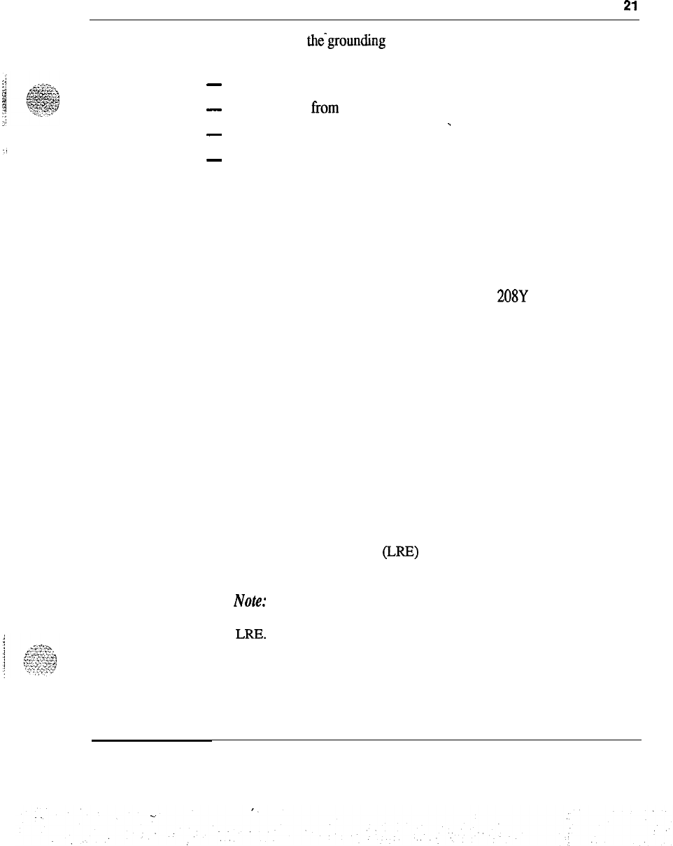
Researching the requirements
21
Failure to follow the~grounding proceduresmay result in an installation that
is:
-
unsafe for personnel working on or using the equipment
-
not protected horn lightning or power transients
.
-
-
subject to service interruptions
-
subject to degraded system performance
Commercial power and grounding requirements
The commercial power source refers to the main AC utility power feed, for
either AC-powered or DC-powered systems. For AC systems, this power is
wired directly to the system. For DC systems, this power source connects to
the rectifiers which convert to -48 V dc for distribution to the system.
In North America, the power supplied can be either 208Y or 240 V ac
nominal. Three phase is not required by single power feeds fromalternate
phases is normal practice where three phase power is available. Refer to
Table 8 for the exact voltage range.
Building ground requirements
Although the SL- 1 system (by design) does not require an isolated AC
ground system, the NEC does. For this reason Northern Telecom
---
recommends the use of an isolated AC ground system. Non-isolated ground
systems are acceptable only where not required by a national code.
This system does not need an isolated AC ground system, but it does need a
single point ground system. Single point ground may be implemented
either by the use of an Isolated Ground (IG) bus in the AC panel to
terminate all AC grounds and other ground reference conductors, or by a
separate logic return equalizer (LRE) ground bus for system ground and
logic returns where a non-isolated AC system is used.
No&: Where required, Northern Telecom will provide an LRE with
each system delivery. Multi-column systems require the use of an
LRR.
installation planning 553-3001-120

22 Researching the requirements
Isolated ground topology
A dedicated Isolated Ground (IG) bus bar is required with this method.
This IG bus is located in the AC panel and serves as the ground window. It
is used for all AC (green wire) grounds as well as logic returns. It also
accommodates a conductor which references to the (+) battery bus in a DC
system. An alternate form of this isolated topology is to use one or more
isolated equalizing bars external to the AC panel but which connects to
ground exclusively by means of the AC IG bus.
Isolated orange outlets are required (as per NEC 250-74 Exception 4).
Grounding conductors shall be routed with the phase conductors (Article
300-20). All ground wiring-for IG receptacles are to be terminated on the
dedicated IG bus per applicable codes (complies with NEC 384-27).
Non-isolated ground topology
In a non-isolated system the AC equipment ground (ACEG) connects to the
metal panel, and the associated conduit may also contact various structural
metal. This ground alone is not adequate for the SL-1 system, but a
dedicated ground conductor which connects to the main building ground is
then used for the main ground window to terminate logic returns and
reference the (+) battery bus. Frame grounds will connect to the ACEG.
Grounding guidelines
---
The following must be observed to implement the single-point ground:
-
All ground conductors must be identified in accordance with local
codes and terminated in a manner that is permanent, resulting in low
impedance connections.
-
Terminations should be accessible for inspection and maintenance
during the life of the installation.
-
All grounding conductors must be continuous with no splices or
junctions and tagged,
“D
O
not remove or disconnect.”
They should also be insulated against contact with foreign grounds.
-
Grounding conductors must be no-load, noncurrent carrying cables
.rX
under normal operating conditions.
Installation planning 553-3001-120

Researching the requirements 23
-
In a steel-framed building, the SL-1 ground interface must have a
connecting reference to the building steel on the same floor on which it
resides (or within one floor).
Note:
Northern Telecom does not recommend the use of building steel
as part of the SL-1 ground system.
-
Proper wire sizing of the System Ground Reference conductor ensures
compliance with this requirement provided the building ground has been
properly installed as per NEC rules and regulations and the associated CEC
regulations.
Using an Isolated Ground bus is often a lower cost method but may not be
allowed by all telcos and may be prohibited by local ordinances.
Note:
All voice and data lines leaving or entering the SL-1 system
(which run external to the building) must have fault protectors that
connect directly to earth ground. Fault protectors provide E&lI/RFI
protection outside of the SL-1 system.
AC service panel
Dedicated versus shared power
Dedicated AC power transformers are preferred; however, a shared
---
transformer or distribution is acceptable.
The following figures identify the differences between dedicated and shared
distribution and between isolated and non-isolated grounds:
Installation planning 553-3001-120
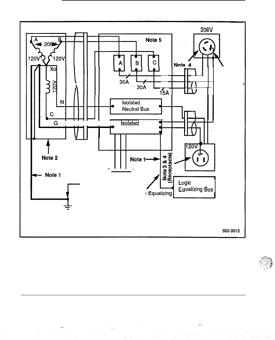
24 Researching the requirements
Figure 1
Dedicated transformer in isolated ground system
Transformer Conduit Meridian SL-1 Service Panel 3nRv
l%A
I
Isolated
J
Ground
(\
Receptacle
I
I I I I I I I
isolated
lb
Ground Bus
l-Hl+rTl-r
Note 6
Cadwelded
or 2 ALCU
Clamps Logic Return
Conductor
bgic
Return
~~~~l~~ing
Bus
Building
Ground
,
s‘::s
._,
.
.
.
6;‘.
:-::G
:
:’
:
2:
.;
:
.;.
,,
..”
Installation planning 553-3001-120
Researching the requirements 25
Notes for Figure 1:
-
Ground conductor should be the same size as the largest conductor run
between the transformer and the AC panel.
Transformer (dedicated for SL-1 and Telco Interface Equipment) shall
provide a secondary voltage of single phase 120/240 or three phase
208Y/12OV and must have a system ground conductor.
Receptacles: All 120V service drops in the equipment room must have
IG type receptacles. Each circuit must have individual hot, neutral, and
ground conductors.
NEMA numbers for receptacles are:
2081240
@
30 A IG-6-30
120 @ 15 A IG-5-15
Panel circuit breakers are:
. .
208Vl24OV 30A
A dedicated service panel should be located in the equipment room.
If the service panel has sufficient terminating points on the isolated
ground bus, the logic return equalizer may not be required.
Installation planning 553-3001-120
Y
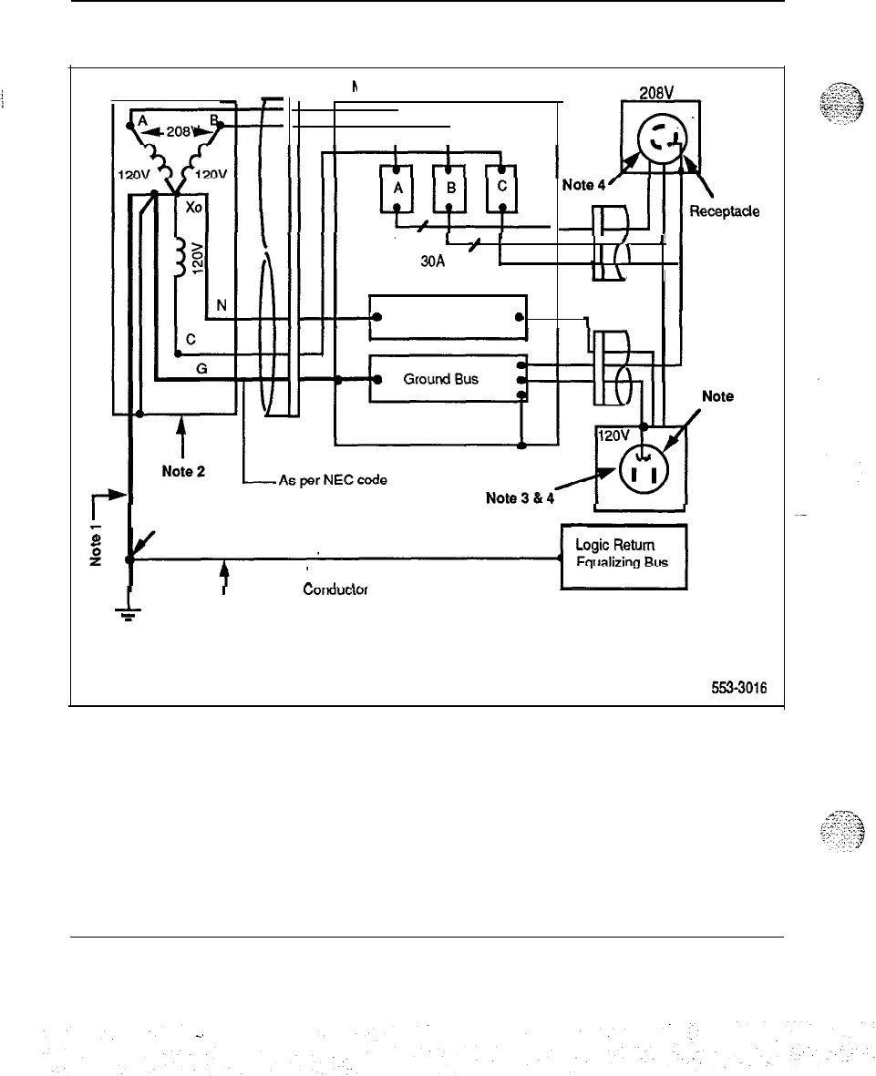
26 Researching the requirements
Figure 2
Dedicated transformer in non-isolated ground system
Transformer Conduit
h
Aeridian SL-1 Service Panel
208V
I
Note 5
Note
4'
-Ad
30A
’
;
’
I
/
=A
1 ;
II\
’
15A
Isolated
e
Neutral Bus
0
Note 7
(Receptacle)
-
Logic Return Equalizing
n--d
___L__
6‘
1,
’
WJIKWCi”’
Note 8
F
Building
Ground
563-3016
Installation planning 553-3001-120
Researching the requirements 27
Notes for Figure 2:
-
Ground conductor should be the same size as the largest conductor run
between the transformer and the AC panel.
Transformer (dedicated for SL-1 and Telco Interface Equipment) shall
provide a secondary voltage of single phase 120/240 or three phase
208Y/12OV and must have a system ground conductor.
Receptacles: Each circuit must have individual hot, neutral, and ground
c
conductors.
NEMA
numbers for receptacles are:
208/240
@
30
A
L6-30
120 @
15 A 5-15
Panel circuit breakers are:
208V/24OV 30A
.
A dedicated service panel should be located in the equipment room.
Auxiliary equipment using an RS-232 interface will, if such equipment
is too remote to be powered from the SL-1 service panel, require a
modem or fiber link to provide ground isolation.
Connection to the building ground source should be made at the same
physical location as the transformer grounding conductor. If the LRE is
connected to a building ground point other than the transformer ground
point, a bonding jumper must be installed between the two points.
Two approved fastening devices or cadwelded devices should be used
here.
Installation planning 553-3001-120
.
.
.’
.:...
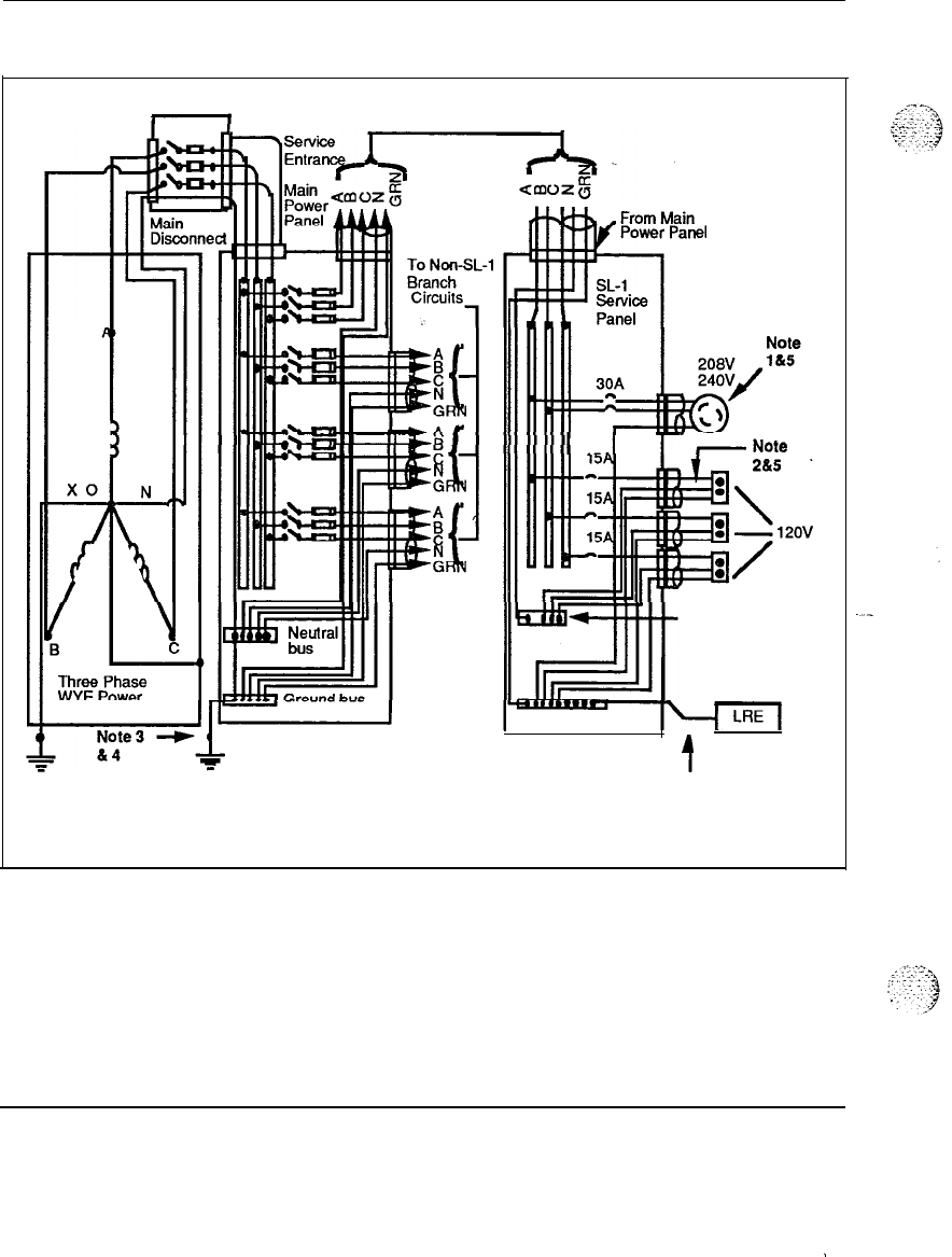
28 Researching the requirements
Figure 3
Shared AC distribution in an isolated ground system
SL-1 Related Wiring Contained
In Rigid Conduit or EMT
el
1
.-.I
r
&Note
Neutral bus
Isolated from
power panel
t
To LRE
Note 6
5539017
Installation planning 553-3001-120
.
‘!
Researching the requirements 29
Notes for Figure
3:
-
An isolated ground receptacle must be used for systems with isolated
ground.
An isloated ground receptacle with individual hot neutral and ground
conductors must be used for systems with isolated ground.
An alternate earthing electrode, if required, must be installed in a
minimum of 6 ft. (1.8m) from the building earth reference.
Connections to the building earth reference must be either cadwelded or
provided with two ALCU clamps.
NEMA numbers for IG ground receptacles are:
208/240
@
20
A IG-L6-20
208/240
@
30
A IG-L6-30
120
@
15A
IG-5-15
Panel circuit breakers are:
208V
30A
240V 30A
Connection to the building ground source should be made at the same
physical location as the transformer grounding conductor. If the LRE is
connected to a building ground point other than the transformer ground
point, a bonding jumper must be installed between the two points.
:,
..:::.
.~,
i.
i,
:::,:::.
.::
‘,:
-!
/
-i..
Installation planning 553-3001-l 20
.
:
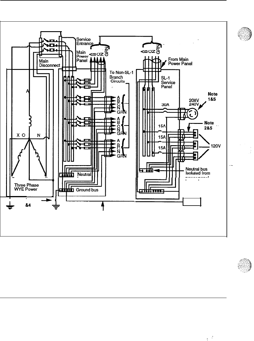
30 Researching the requirements
Figure 4
Shared AC distribution in a non-isolated ground system
SL-1 Related Wiring Contained
I I
In Rigid Conduit or EMT
Note 3
-b
bi!EE!l,
,
LRE
To LRE
Note 6
5633016
installation planning 553-3001-120
. .
:
:
Researching the requirements
31
Notes for Figure 4:
-
An isolated ground receptacle must be used for systems with isolated
ground.
An isloated ground receptacle with individual hot neutral and ground
conductors must be used for systems with isolated ground.
An alternate earthing electrode, if required, must be installed in a
minimum of 6 ft. (1.8m) from the building earth reference.
Connections to the building earth reference must be either cadwelded or
provided with two ALCU clamps.
NEMA numbers for IG ground receptacles are:
208/240
@
30
A IG-L6-30
120 @
15 A IG-5-15
Panel circuit breakers are:
. .
208Vl24OV 30A
Connection of the LRE to the building ground source should be made at
the same physical location as the transformer grounding conductor. If
the LRE is connected to a building ground point other than the
transformer ground point, a bonding jumper must be installed between
the two points.
Installation planning
. .
553-3001-l 20
32 Researching the requirements
Auxiliary power requirements
Integrated terminals, printers, modems, and data units require local power.
Power for devices located in the equipment room must meet the following
criteria:
-
wired and fused independently of all other receptacles
-
tagged at the power panel to prevent unauthorized interruption of power
-
not controlled by a switch
-
referenced to the same building interface point on the building system
ground as the SL-1 AC panel ground
Isolated service receptacles
For isolated ground systems, the auxiliary power receptacles used should be
12OV, 6OHz, 15A, individually fused, isolated ground circuits terminating
on NEMA non-locking type IG 5-15 such as Hubbell, Cat. No. IG-5262,2-
Pole, 3-Wire, orange duplex receptacles. A green conductor must be used
for extending the safety ground and must be wired according to the isolated
ground specifications.
Note:
This requirement is based on safety concerns and exceeds
NRC/CRC requirements.
Non-isolated service receptacles
For non-isolated ground systems, the auxiliary power receptacles used
should be 12OV, 6OHz, 15A, individually fused circuits terminating on
NEMA non-locking type 5-15.
In non-isolated ground systems auxiliary equipment which connects to the
SL-1 system should be isolated through the use of fiber optic signal cables
such as RS-232-C. Failure to provide this isolation will defeat the single
point ground.
Power Fail Transfer Unit (PFTU) powering
The PFIXJ, when used with AC systems, operates with a separate 120 V ac
to 48 V dc power supply. If the AC system is not backed-up (for example,
when no UPS is present), the
PFIU
power supply requires a separate and
dedicated auxiliary power outlet. Power to the PFTU is terminated when
the system power goes down and vice versa.
Installation planning 553-3001-120
;
(.’
:.
:
;y:.
:
:
:’
!
,,
,
.
,,
Researching the requirements 33
CabHng
This section identifies the various cabling used in the SL-1 system and
provides some guidelines for cabling. Equipment placement in relation to
cable lengths should be considered and planned for. Depending on your
system and future expansion (of PE modules, for example), the cables you
choose must be the right length.
Cable types
All cables must be designated (tagged) at both ends. The SL-1 uses at least
five types of wiring:
-
Twisted-Pair Telephone Cables
-
25-Pair MDF Cables
-
Twisted-Pair Shielded and Non-Shielded Cables
-
Interface (I/O) Cables
-
Power and Ground Cables
Twisted-pair telephone cables
These cables carry analog voice and digitized voice/data information
between distribution frames and devices located throughout the office.
They run from cross-connect panels to jacks (8-pin modular) located within
8
feet (2.4 m) of each peripheral device.
2L,Pair MDF cables
These cables carry voice and data information between the SL-1
UEMs
and
the distribution frame. When the cables are run from the UEM to the
distribution frame, one end of the cable must be equipped with a 25-pair
female connector which terminates on the cabinet I/O panel.
Twisted-pair shielded cables
These cables are used to interconnect the trip power monitoring connections
between power interface units and the main distributing frame. Typically, a
16 AWG, stranded (Belden type 8408-2 conductor or equivalent) type
shielded cable is used for trip connections. All other connections are
serviced by non-shielded, 16 AWG stranded cable.
Installation planning 553-3001-l 20

34 Researching the requirements
Interface (l/O) cables
-
I/O cables are typically 25conductor flat-ribbon or round cables interfaced
through RS-232-C connectors. These cables are used to connect data units
to printers, host computers, and modems.
UEM cable routing
Cables may be routed internally in the UEM horizontally in front and at the
rear of the card cage, vertically on the right side only and vertically through
square holes near the rear of the DEM. Cables may be routed externally in
the back of and on the left and right side of the UEM between the EMI/RFI
I/O panel and the rear cover. The cables may be routed in these channels up
to the top of the column or down to the floor through the pedestal.
Note:
Routing cables on the inside of a UEM from the front to the
back on the left or Power Supply side is not recommended. This is
because of the limited access in routing the cables and of the effects of
EMI/RFI noise generated in this area to signals in the cables.
Network to PE cabling
IPE cabling from Network to PE originates from the faceplate of the
Superloop Network card and extends to the backplane connectors on the
Controller card of the
lPE
Module.
---
PE cabling originates from the faceplate of the Network card to the
faceplate of the Dual Loop Buffer.
Power and ground cables
For AC-powered systems, a 9-foot, three-conductor line cord is normally
supplied except in areas where conduit will be required. For DC-powered
systems, wiring is generally done through conduit.
installation planning 553-3001-120
I
c
Researching the requirements 35
Cable access requirerients
The customer is responsible for supplying all access for station, feeder, and
riser cabling including where necessary:
-
conduit
-
floor boring
-
boring all major walls on a particular floor
-
access into hung ceilings, including removal and replacement of ceiling
tiles
Fire protection and safety precautions
Fire protection and prevention
Building, fire, and safety codes establish the degree of protection required
for an installation. Additional information is available from the National
Fire Protection Association in its publications entitled “Standard for the
Protection of Electronic Computer/Data Processing Equipment (NFPA 75)
and “National Electrical Code”
@VFPA
70).
Properly locating and installing sprinkler heads, fire and smoke sensing
devices, and other fire extinguishing equipment require expertise. Local
codes and experts should be consulted during the planning stage, and the
recommendations of insurance underwriters and local building authorities
should be sought and followed.
Some fire precautions can be implemented during the construction phase of
preparation for an installation. Walls enclosing the equipment area should
extend from floor to ceiling, and the walls, floor, and dropped ceiling, if
any, should be constructed of noncombustible covering. Shatterproof
windows and sprinklers outside and above the windows should be installed
to prevent the spread of fire from an adjacent building.
If the structural floor is made from combustible materials, it should be
covered with a noncombustible covering, and the space between the raised
and permanent floors should be cleared of all debris before the system is
installed.
Storage areas and the roof or floor above the equipment room should be
watertight since water leakage from the floor above could easily damage the
equipment below. In addition, ducts and plumbing work for air-
Installation planning
553-3001-l 20
36 Researching the requirements
conditioning systems should be designed to inhibitthe spread of fire, heat,
and smoke from one part of a building to another. Smoke detectors should
also be installed.
Services such as steam, water, and power should be checked regu.Iarly, and
pipes should be inspected for excess condensation,.leaks, and corrosion. If
power connections are made beneath a raised floor, waterproof electrical
receptacles and connectors should be used.
Recommended fire extinguishing systems
In
most cases,
carbon dioxide or water sprinkler systems are to be used.
Water sprinklers are generally less expensive than the carbon dioxide kind.
Specifically, dry-pipe water sprinklers are strongly recommended since this
type will interrupt power to the room and open a master valve to fill the
overhead sprinklers.
Carbon dioxide systems are also effective in containing a fire, but they
quickly exhaust the available oxygen supply. If a carbon dioxide system is
used, an alarm should sound warning onsite personnel of the release of
carbon dioxide. For health and safety reasons, employees must be
evacuated within 30 seconds of the release.
q
CAUTION
I
Use of other fire extinguishing systems
.
Northern Telecom does not recommend the use of
Halon
or any other fire extinguishing system not stated
above. Northern Telecom is supported by the
Environmental Protection Agency to enforce any
restrictions on the use of other fire extinguishing
systems.
Installation planning 553-3001-120
Researching the requirements 37
Security
precautibns
and safeguards
Existing practices of building security should be extended and improved to
provide adequate protection for the equipment.
Safeguards such as tamperproof keylock door controls and electrically taped
glass doors and windows can be tied into an alarm system. A monitoring
unit using closed-circuit television can also be installed.
Protect critical data such as business records or other information by storing
backups well away from the equipment room. A regular updating program
is highly recommended.
Safety procedures and training
Company personnel should be taught how to respond to emergencies. Some
companies designate such individuals as security members. Training could
include how and when to evacuate personnel and records, to notify the fire
department, to shut off all electrical power, and to properly handle fire
extinguishers.
In addition to training, temperature and humidity monitoring devices (both
visual and audible alarm signals) should be installed in the equipment and
storage rooms so that individuals can respond quickly to an emergency.
Occupational noise exposure
When employees are subjected to noise levels exceeding those listed in
1910.5 of the OSHA Standards, or local standards internationally,
administrative and engineering controls should be initiated. If these
controls fail to reduce sound levels effectively, protective equipment should
be provided. The acoustic noise generated by an SL-1 UEM column should
not exceed 6OdBA (decibels “A”-weighted). Depending on the ambient
external temperature, the acoustic noise could be as low as 45 dBA.
Installation planning 553-3001-120
:
:

38 Researching the requirements
Installation planning 553-3001-120
.a
:
‘. .
. .

Planning the site
39
Planning the site is an important element to consider when planning the
installation of an SL-1. It impacts the installation costs, operation and
maintenance and can have an overall effect on system performance.
Selecting a site
Sites should be selected and evaluated according to the followingcriteria
and the detailed information given in this document:
Space
The proposed site should provide adequate space for system unpackaging,
system installation, operation, potential expansion, service, storage of
supplies, and system operator area (if applicable). It should also provide
sufficient cooling for efficient operation of the equipment and a suitable
operating environment for the system.
Locat ion
The location should be convenient for delivery of equipment and close to
related work areas for efficient operation. The location of related equipment
(distribution frame and batteries) must be considered when selecting the
site.
Power and grounding
Sufficient power and proper grounding facilities must be available.
Structural integrity
The floor must be strong enough to support anticipated loads, and the
ceiling must be able to support overhead cable racks, if applicable.
Installation planning 553-3001-120

40 Planning the site
Developing the site
-
After selecting a site, the following items must be considered during site
development:
-
Space and equipment layout requirements
-
Equipment
rmrn
accessories
-
Detailed floor plans and loading requirements
-
Building cable plans
-
System wire routing
-
Cable termination points
The equipment room
Space and equipment layout requirements differ with each installation,
depending upon equipment selected and the available physical area. The
following categories of required space should be considered when planning
site needs:
-
Primary storage
-
Secondary storage
-
Maintenance/Technician area
Primary storage
The floor area required for an SL-1 depends on the number of columns of
UEMs
ordered, the length-to-width ratio of the area, and the location of
walls, partitions, windows, and doors. To determine the exact layout
required, prepare a detailed floor plan after reading all of the requirements
provided in this section.
Operating needs determine the location of free-standing peripherals like
printers and terminals. Printers and terminals must not exceed the
maximum distances defined for their interface circuits. Wall jacks and
outlets must be provided for all devices located in the equipment room.
Within a system there are certain requirements that must be met when
drawing up the equipment room floor plan.
Installation planning 553-3001-120
s.
.:
:
.:
Planning the site
41
Note:
Sample floor plans may
.vary
from your own depending on your
system needs and the size/arrangement of your equipment room.
Follow
the engineering guidelines as specified in
System engineering
(553-3001-151).
Secondary storage
Provide space for the storage of disks, printer paper, printouts, and daily
reports within the equipment area. A secure storage room for spare parts is
recommended.
Similar environmental conditions should be maintained for storage and
operation areas. If it is not possible to maintain the storage area
environment exactly the same as that of the operating equipment, adequate
time must be allowed for stored materials to adjust to the equipment room
environment before they are used.
Maintenance/Technician area
. .
The maintenance/technician area is used primarily to store tools, test
equipment, manuals, spare parts, and as an online work center. The area
should have good lighting and convenient access to the equipment. Typical
items that would go into a maintenance/technician area are:
-
shelf for instruction books
-
spare parts storage room
-
paper storage area
-
locking cabinet or storage area for back up disks
-
table or desk
-
printer/VDT or equivalent device
Equipment room accessories
The following equipment room accessories are recommended:
!
‘_3
.:.:,
!
“‘_L’
-
Temperature/humidity recorder(s)
-
A key or combination with option
key&k
for the switchroom door
(electric locks, such as push button access code or card reader, are not
recommended unless battery backup or key override is provided)>
-
Desk or table, file cabinet, and storage shelves
Installation planning 553-3001-120
42 Planning the site
-
Storage cabinets for spare parts, backup tapes or disks, and printer
Paper
The floor plan
Since the space requirements and the overall layout of the equipment room
can have an effect on the installation, operation, and maintenance of a
system, a detailed floor plan should be drawn up for each site.
...>.;,.%
The floor plan should show the location of utility closets and cross- connect
terminals. All cables running from distribution points to the zones should
be clearly designated with the zone ID. The zones are typically the
termination point of conduits throughout the office. (See Figure 8 “Sample
building cable plan” for an illustration of zones.) Within a zone the cables
should be identified by their number within the zone.
Note:
According to the National Fire Code, equipment must be
located at least 12 inches from a sprinkler head. If your system has
.-
four
UEMs
and a cable rack, do not place the equipment directly under
any sprinkler heads.
Consider the following guidelines when planning the equipment room floor
plans:
-
a recommended minimum ceiling height of 8 ft (2436mm) or greater
---
-
a minimum distance between equipment aisles of 30 inches (760mm)
-
a minimum distance between end of aisle stacks and wall and between
rows of 3 ft (914mm)
-
location of modems, printers, and terminals
-
size and location of reserve power
-
size and location of cross-connect terminal
-
size and location of maintenance/technician area
-
number of rows and future expansion needs
(RF’E
or Meridian Mail, for
example). Refer
to System engineering
(553-3001-151) for guidelines
on system expansion.
.
;
. . .
.>
-4
<;?I
$7
Installation planning 553-3001
-I20
.
.
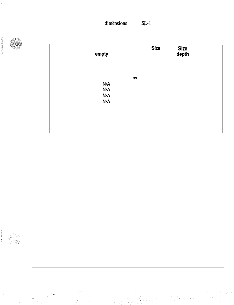
Planning the site 43
The weight and dimgnsions of the SL-1 system should also be considered:
Table 9
Weight and dimensions of an SL-1 system
Assembly Weight Weight
SiZS
SiZe
Size
item
empty full width
dipth
height
Pedestal
40
ibs.
70
ibs.
32
in.
26
in. 10 in.
Top Cap 15 ibs. 15 ibs.
32
in.
22
in.
4
in.
UEM
50
ibs. 130 tbs.
32
in.
22
in. 17 in.
1 Module stack
N/A
215 ibs.
32
in.
26
in.
31
in.
2 Module stack
N/A
345
ibs.
32
in.
26
in.
48
in.
3 Module stack
N/A
475
ibs.
32
in.
26
in.
65
in.
4 Module stack
N/A
605
ibs.
32
in.
26
in.
82
in.
Note:
Multi-column systems require a three inch spacer between each column for
cable routing and to provide EM1 shielding.
.
installation planning 553-3001-120
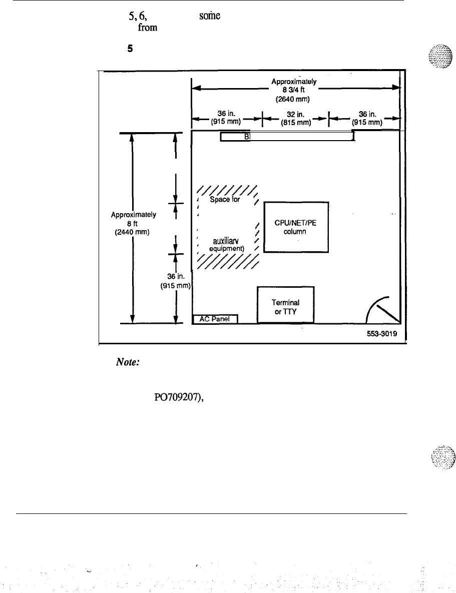
44 Planning the site
Figures
5,6,
and 7 show
sotie
sample equipment room floor plans. These
may vary from your own.
Figure 5
SL-1 Option 21 equipment room floor plan
I
36 in.
(915 mm)
t
25
in.
(65
mm)
f
IX cross connect terminal
~qg~~w
,
/
1 additional ,
*
equipment ,
‘(such as reserve
f
1
power supply or
f
auxiliarv
/
Note:
This sample floor plan may vary from your own depending on
your system needs and the size/arrangement of your equipment room.
A template for floor drilling procedures is available. The drawing,
(number PO709207), is delivered with the packing instructions.
Installation planning 553-3001-120
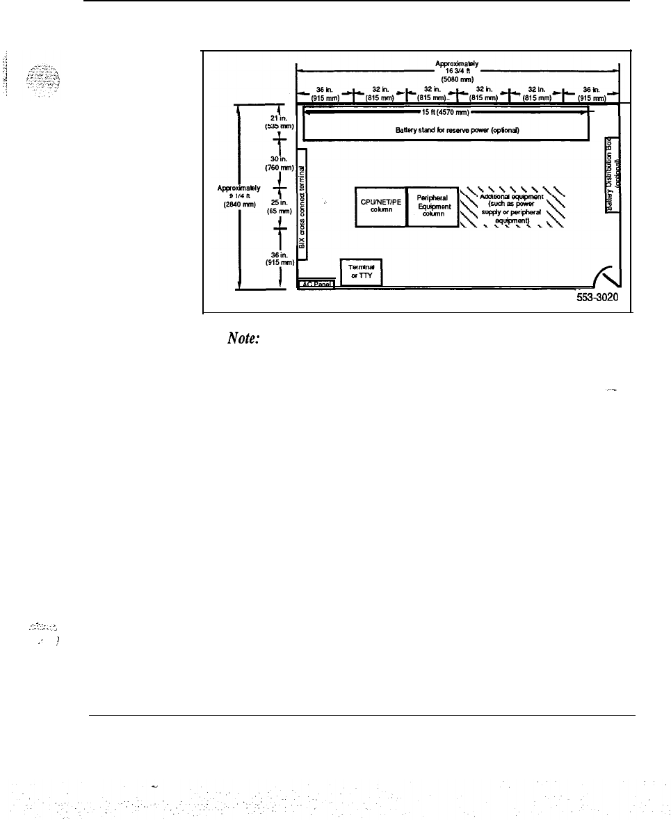
Planning the site 45
Figure 6
SL-1 Options 51 and 61 equipment room floor plan
‘5533020
Note:
This sample floor plan may vary from your own depending on
your system needs and the size/arrangement of your equipment room.
.
.‘.-‘,-~~.-‘,
,’
,Y
Installation planning 553-3001-l 20
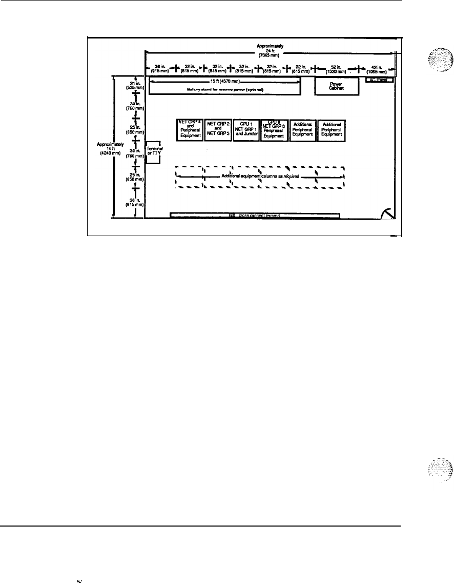
46 Planning the site
Figure 7
SL-1 Option 71 equipment room floor plan
553-3021
Note:
This sample floor plan may vary from your own depending on
your system needs and the size/arrangement of your equipment room.
SL-1 Option 71 may also expand to a second row of Peripheral
Equipment modules.
Installation planning 553-3001-120
Planning the site 47
Floor loading estimates
Floor loading estimates should be obtained in order to plan for proper
stacking of modules. (Floor loading is the weight of the system divided by
the occupied floor arena Point loading is the local pressure exerted by the
system feet on the floor.)
Table 10 shows the floor loading estimates for stacking an SL-1 system.
The estimates given represent a fully-loaded module complete with
pedestal, maximum circuit pack alIowances, power supplies, and cables.
Table 10
Floor loading estimates
Modules LBS/FT2
(kPa) Point Load
(Ibs/in2)
(kPa)
3ne
38.1 (1.8 kPa) 11 .O (75.8 kPa)
Two 60.3 (2.8 kPa) 17.3 (119 kPa)
Three 82.4 (3.9 kPa) 23.7 (163.4 kPa)
Four 104.6 (5 kPa) 30.0 (206.8 kPa)
Note: The numbers under “LBS/FT2 (kPa)” are based on a
floor area of the system of 5.64 square feet. These numbers
do not include the weight of the optional overhead cable rack.
The numbers under “Point Load (Ibs/in2) (kPa)” are based on
distributing the system weight among four feet, each with an
area of 4.91 square inches; these numbers do not reflect the
use of optional casters.
Installation planning 553-3001-120
48 Planning the site
-
The building cable plan
The building cable plan should be divided into zones. The zones are
typically the termination point of conduits throughout the office. Each zone
on the building cable plan should be identified with a letter or number, and a
block of numbers should be assigned to each zone. Be sure to leave room
for expansion. See Figure 8 “Sample building cable plan” for an illustration
of zoning.
In addition, the following information and guidelines should be consider&
Each telephone, console, or data set connected to the SL-1 requires
telephone wire run from a nearby telephone jack to a cross-connect
location. Also, each component connected to the system requires a
termination. (Modular jacks should be within 8 ft
[2436 mm] of the device.) The location of all devices that interface
with the SL- 1 should be known.
Telephone directory number, features, and Office Data Administration
System (ODAS) designator of each telephone in the office should also
be known.
-
Three-pairs of telephone wire should be provided from the telephone or
data set location to the distribution frame. Location of all distribution
points (main and intermediate) should be known.
Consoles require a 16-pair (or
25pair)
cable equipped with an
Amphenol-type connector.
If any existing wire is to be used, ownership of that wire must be
clearly defined.
All wiring carrying high-speed data must pass a verification test at the
time of installation. The test is performed as part of the installation
procedures.
Installation planning 553-3001-120
-..
:.:;
.\
--.;.,:.j
:
:
.,
.
..‘-
a
.

:: ..,r
.
.~.
::
.:.
.:.:::::
Planning the site 49
-
A random sampling of in-place wiring’is taken during a site survey to
ensure that it meets specifications for high-speed lines.
-
When telephone cable is run in conduit, that conduit must not be used
for any other wiring. The location of conduits and floor ducts, for
example, should be known.
-
The wiring plan should show the routing of all wiring, the location of
each telephone, console, or data set, and any other relevant information
about the device. It should also show the location of any power outlets
that the device will require. Power outlets must be equipped with
safety ground.
-
Flat under-carpet cables are not recommended.
-
Bridge taps for sets are not recommended.
:i .:.::..
?
j
:
:::
!:
;.
‘,,
. . . .
.
Installation planning 553-3001-l 20
-.
:
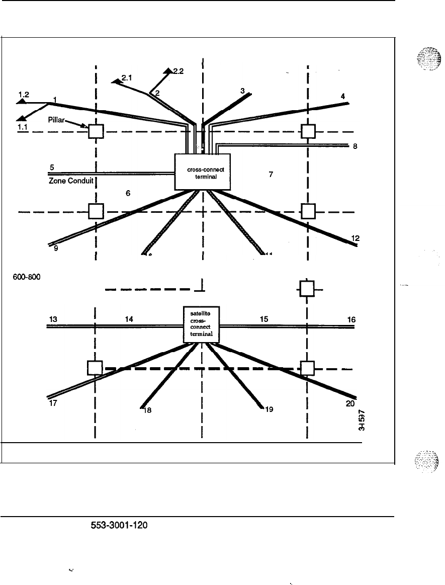
50 Planning the site
Figure 8
Sample building cable plan
ZONE
I
ZONE ZONE ZONE
I .
Each Zone
Approximately
6CG600 sq. ft.
I I I
----- P
---m-B
1
-B-B-- --
l
-----
6
z
h
8
Installation planning
5!53-3001-120
L.
~

Planning the site
51
Wire routing
The routing of all wires for the SL-1 must be specified as part of the plan.
To plan wire routing, establish the start and end point of each cable relative
to the location of telephones in the office. Remember that each modular
jack (8-pin or 6-pin, for example) must be within 8 feet.
(2.4 m) of the telephones.
At this point the construction of the office must be investigated to determine
the best wiring routes. Consider the following information when
performing this task
Floors
Telephone wire travels along floors in one of two ways:
-
Out in the open: In some cases wires are tacked to the surface of walls
and other physical structures. For the safety of employees, wire should
never be stretched across the top of floor. Run the wires along
baseboards, ceiling mouldings, or door and window casings.
-
Concealed: In other cases wires are run inside a floor conduit. The
conduits can travel between utility closets and jack locations. In some
cases the floor conduits connect to a conduit passing through walls or
ceilings. In all cases the conduit must be used exclusively for
telephone cables. The use of under-carpet cables is not recommended.
Ceilings
The National Electrical Code and local building codes specify what types of
telephone wire may be run in each type of ceiling. Local building codes
take precedence.
Walls
Wiring that needs to be run horizontally cannot be blind fed through walls.
Cables that need to be run vertically should, when possible, run inside a
wall, pole, or similar facility for vertical wire drops.
Between floors
Telephone utility closets should be located as closely to one another as
possible. In many cases, contractors are hired to install the conduit. Local
coding laws will specify whether a licensed contractor is required.
installation planning
553-3001-l 20

52 Planning the site
Electromagnetic Interference (EMI)
Data degradation may occur if wires travel near strong sources of
electomagnetic interference. See “The equipment room environment” in
this document for common sources of interference.
Termination points
Once the routes for the wires have been determined, the termination points
for the these wires must be decided. The cables can terminate at various
locations:
-
main cross-connect terminal-typically in the equipment room
-
intermediate cross-connect terminals-typically on each floor in
telephone utility closet
-
wall jacks or terminal boxes-typically near the
final
device location
(within 8 ft [2.4 m])
Distribution frames
House cables terminate on the vertical side of two-sided frames and cross-
connect to equipment which is typically located on the horizontal. When a
color field approach is taken, the house cables typically terminate in the
blue field and the equipment terminates on the purple (USA) or white
(Canada) field.
In all cases the block where the cables are terminated must be clearly
designated with the cable location information and the cable pair
assignments.
Note:
A log book (cable record) of all termination information should
be kept See Table 11 for an example.
installation planning 553-3001-120
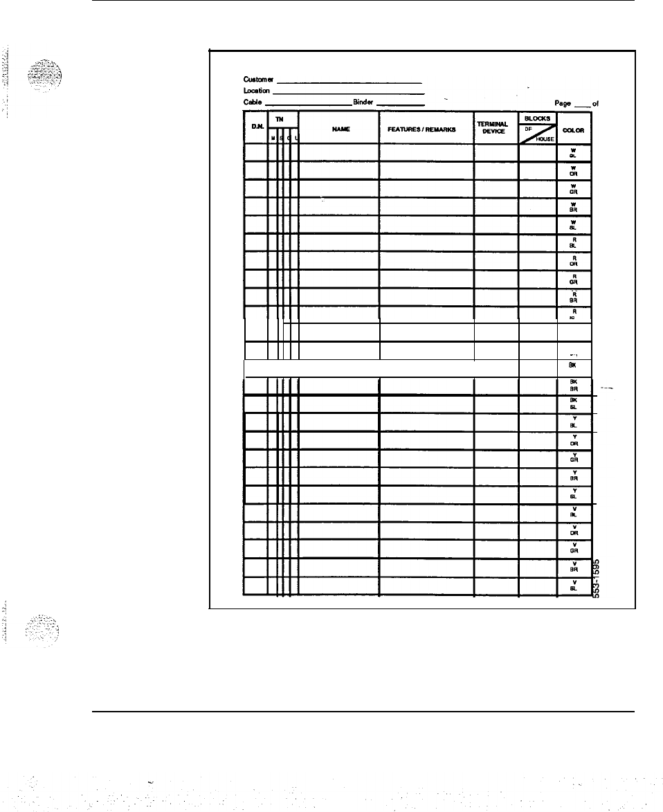
Planning the site 53
Table 11
Sample cable record
CABLE RECORD
I iiiii
II
-.
I
I I sl(
OR
Installation planning 553-3001-120

54 Planning the site
Installation planning 553-3001-120
55
Preparing for delivery
The route the equipment must take from the receiving area to the
installation area must be studied in advance. The route should be measured
to ensure problem free delivery of the equipment. The following factors
must be considered:
Considerations
-
size and security of the loading and storage areas
-
capacity and availability of elevators
-
the number and size of aisles and doors en route
-
restrictions such as bends or obstructions in halls
-
floor loading capacity of the loading, storage, and equipment room
iUC!aS
-
number of steps and stairways
-
dimensions of fully-loaded, packaged system complete with shipping
pallet (39”W x 3O”D x
70%)
Note:
The SL-1 system is shipped with a software package, three
UEMs, a pedestal, and a shipping pallet (five inches high). The fourth
UEM is shipped separately. Refer to Table 9 for the weight and
dimensions of an SL-1 system.
2
,.-.-:.“::
..j
.i .’
,..
.i.
i
“‘-
‘.I
Installation planning 553-3001-120
..A
.

56 Preparing for delivery
In addition, here are some questions to consider when preparing for
delivery:
-
Has a request been made for equipment delivery?
-
Is a list of all equipment ordered available on site?
-
Are transportation arrangements to premises completed?
-
Is assistance available to prepare the switchroom?
From unloading area to equipment room
-
Are unloading/unpacking facilities available?
-
Are unloading/unpacking tools available? (pallet jack, for instance)
-
Is there access to and from unloading area to equipment room?
-
Is the equipment room threshold large enough for the equipment to
enter?
Note:
The equipment should be located as close to the final
installation area as possible. This will provide for an easier, perhaps
safer, installation.
Installation planning 553-3001-l 20
1:;
.
.,
‘I
-‘.‘-+
:,
‘;
_
_
_
_
.
.
_
.
.,^.
-
._.
,.._
,’
Preparing for
delivery
57
Equipment handling precautions
The following general guidelines should be followed when handling
SL-1
equipment:
-
Circuit packs, disks, and tapes are very sensitive to
s.tatic
discharge; all
static electricity should be discharged-from the body prior to handling.
-
Circuit packs should be handled carefully: only handle packs by the
edges, only remove and insert packs when necessary, and only unpack
or handle packs away from machinery such as electric motors or
transformers.
-
If your system is using reserve power, the batteries may weigh in
excess of 500 pounds each and may be packaged four to a shipping
pallet. To prevent stressing of the floor, do not place the pallets side-
by-side in the equipment room.
-
Special ramps supplied with the product must be used to move the
product off the pallet. Follow the instructions on unloading the
machine provided on the side of the product. (See CAUTION box
below.)
CAUTION
Lifting the pedestal
The pedestal of the SL- 1 must never be pried up in
order to lift the stack. This could cause major damage
to the pedestal. Carefully slide the pedestal and
associated stack manually, and use the special ramps
provided with your system.
Installation planning
553-3001-120
.
.
.I.-

58 Preparing for delivery
Installation planning 553-3001-120
-.
‘.
:
.
.
:
_
‘.
59
Preparing for installation
The following items should be provided at the time of installation:
-
Work orders
-
Equipment room floor plan
-
Building cable plan
-
Installation, Administration and Maintenance Manuals, and User
Guides
-
Installation plan
-
Delivery equipment (pallet jack, for instance)
-
Unloading/unpackaging instructions
Work orders
The Work order may include:
-
Terminal Number (TN) assignments
-
Directory Number @N) assignments
-
individual terminal, data unit feature assignments
-
terminals and user profiles
-
system and terminal cross-connect assignments
-
a detailed listing of the equipment ordered
-
administration database entries for features and services
Note:
The work order will vary depending on the distributor for a
specific system.
Installation planning 553-3001-120

60 Preparing for installation
Equipment room floor plans
The equipment room floor plans should show the location of:
-
each SL-1 module, power module, and future expansion module
(UEM)
-
a reserve power unit (if applicable)
-
maintenance and administration terminal and printer (if equipped) and
printer locations (if applicable)
-
the cross-connect terminal
-
the AC panel and outlets
-
any cable racks
-
miscellaneous external equipment (data units, modems, etc.)
-
auxiliary processors
Note:
The suggested floor plans are provided for your assistance.
Depending on the complexity of your equipment room, your floor plan
may vary from the ones provided in this document.
Installation planning 553-3001-120
Preparing for installation 61
Cabling plan
-
The cabling plan should show:
-
cable routing and designation information
-
location of peripheral devices and pr$rters (if applicable)
-
directory numbers (DNs) assigned to each peripheral device and Office
Data Administration System (ODAS) designators (if the software
package is equipped)
-
features available to each terminal
-
type of cable
or
wiring to each terminal, printer, and PC
-
location of cross-connect terminal
-
location of conduits, floor ducts, including access points (junction
boxes and hand-holes)
-
auxiliary processors
Installation planning 553-3001-l 20

62 Preparing for installation
The installation plan
-
The installation plan may consist of a floor plan, a cabling plan, and an ITS
(Installation and Test Sequence) chart, The chart shows typical installation
tasks, the sequence of the tasks, and task start and duration information.
Manuals
The following manuals should be at hand when installing an SL-1:
-
SL-1 master index (553-3001-000)
-
SL-1 installation and maintenance guide
-
SL-1 planning
&
engineering guide
-
SL-1
Xl1
software guide
-
Product Bulletins (where applicable)
-
User Guides
. .
See the References list in “About this document” located at the beginning of
this publication for more information.
Preinstallation inspections
The following items should be inspected and signed off prior to starting the
installation:
-__
-
Equipment room
-
General inspections
-
Reserve power (if applicable)
Installation planning 553-3001-120

Preparing for installation 63
Equipment room inspections
An equipment room inspection ensures that the following conditions are
met:
-
physical and environmental requirements met
-
system power and utility outlets installed and tested
-
lighting installed and working
-
AC power distribution installed according to Northern Telecom
specifications
-
equipment room is dry, clean, and ready for installation
-
equipment locations have been marked on the equipment room floor
-
entranceways, doorways, halls, and elevators from the loading dock to
the equipment room are large enough for system transport
_
-
terminal, printer, and PC locations ready
-
sufficient wiring is provided
-
single point grounding is implemented
-
sufficient and appropriate terminal connecting blocks are provided_-
Installation planning 553-3001-l 20
L.
64 Preparing for installation
General inspections
General inspections ensure that the following conditions are
met
-
building cross-connect terminals are provided
-
conduits or floor ducts to terminal locations are‘installed (including
service fittings)
-
access conduit for raceway is in place
-
sufficient terminal blocks are provided
-
sufficient cross-connect
yire
is provided
Reserve power inspections
For reserve power inspections if batteries are used, ensure that the following
conditions are
metz
-
reserve power room is well ventilated and operating at optimum
temperature (specific gravity readings are based on a temperature of 77”
F (25” C)
-
proper lighting is available
-
reserve power room is located within manufacturer’s recommended
proximity to the switch
-
protective equipment is available (goggles, face shields, acid-resistant
gloves, protective aprons, water for rinsing eyes/skin, and bicarbonate
sew
-
reserve power room is well secured
-
floor loading requirements are met
-
reserve power room is accessible (no blocking of doorway)
-
noise levels meet OSHA standards 1910.5 or local standards
internationally
-
reserve power area properly interfaces to the equipment
Note:
For detailed instructions on battery usage, see ANSI/IEEE
Standard 450-1987: “IEEE Recommended Practive for Maintenance,
Testing, and Replacement of Large Lead Storage Batteries for
Generating Stations and Substations.”
Installation planning 553-3001-120
Preparing for installation 65
An Uninterruptable Power Supply (UPS)
isused
for reserve power in
AC-
powered systems. It includes basic and supporting equipment, including
rectifier/charger, inverter, controls and instrumentation. A battery bank is a
separate item but may be required together with the UPS. The following
items should be inspected and signed off prior to starting the installation:
-
Environmental requirements are
metz
both operating and
storage/transportation.
-
Other requirements are met such as flammability, reliability (MTBP),
and electrostatic discharge.
-
Since a UPS also makes use of batteries, see “Reserve power
inspections” above for more details on pre-installation inspections.
Note:
Refer to the manufacturer’s specifications for details on the
storage and operating environment of UPS. Temperature and humidity
ranges should be considered for proper maintenance of the UPS.
Installation planning 553-3001-120
Y
:.
..
,..
:.:
SL-1
System options 21,51,61,71
Installation planning
Copyright Q 1990 Northern Telecom
All rights reserved.
Information subject to change without notice.
Release
1
.O
Standard
January 29,199O
Printed in U.S.A.
mt
northern
talactlm
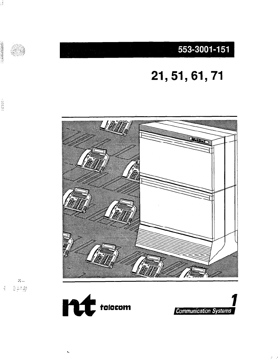
SL-1
System options
21,51,61,71
System engineering
Standard
-..
.,..
,j
;;
:
:
r-y
:-
..,/
northern
talaeam
c
Meridian
I
:
:

.
.
.:_
SL-1
System options
21,51,61,71
System engineering
Publication number:
553-3001-151
Document Status: Standard
Document release: 1 .O
Date: January
29,199O
. .
,.
.
.
.
.:.:.
,;,
,..._
_,
,~
._
,
.:
0
1990 Northern
Telecom
All rights reserved.
System engineering
ii
Revision history
January
29,199O
Standard release 1 .O
System engineering 553-3001-151

iii
About this document
General information
The following document has been updated to include new naming
conventions and system engineering guidelines for the SL-1 System.
Acronyms and abbreviations for the new names are identified in the text
using parentheses.
This section provides the necessary information to:
-
determine the equipment requirements for an SL-1 installation
-
configure and assign equipment in the system
-
distribute traffic equally over the system components
-
maintain traffic distribution and equipment utilization levels when
adding or removing equipment or when altering the system
configuration
Note: The figures and limits used in this section are not necessarily
typical and should not be interpreted as limits of the system capacity.
The figures should be altered to suit the application of a particular
system. Memory and real time figures, which vary for each generic of
SL-1, are given in an appendix to this publication.
System engineering 553-3001-l 51
iv About this document
References
See the SL-I planning
&
engineering guide
for
-
Master index
(553-3001-000)
-
System overview
(553-3001-100)
-
-
Installation planning
(553-3001-120)
-
System engineering
(553-3001-151)
-
Power engineering
(553-3001-152)
-
Sparesplanning
(553-3001-153)
-
Equipment identification and ordering
(553-3001-W)
See the list of fine and trunk circuit descriptions in
the Master index
(553-3001-000) for specific references to lines and trunks.
See the SL-I installation and maintenance guide
for
-
System installation procedures
(553-3001-210)
-
Circuit pack installation and testing
(553-3001-211)
-
Installation procedures for telephone
sets and attendant consoles
(553-2201-215)
-
Extended systems installation
(553-3001-250)
-
Disk drive upgrade procedures
(553-3001-251)
-
General maintenance information
(553-3001-500)
-
Fault clearing (553-3001-510)
-
Hardware replacement
(553-3001-520)
See the SL-1 XII software guide
for an overview of software architecture,
procedures for software. installation and management, and a detailed
description of all Xl 1 features and services. This information is contained
in two documents:
-
XII software management
(553-3001-300)
-
XIIfeatures
and services (553-3001-305)
See the SL-I XII input/output guide
(553-3001-400) for a description of all
administration programs, maintenance programs, and system messages.
System engineering 553-3001-151
s.
V
Contents
System organization and capacities
Option 21
Options 51 and 61
Option 71
Universal Equipment Modules
CUPE
UEM
(NT8Dl
lAC/DC)
Description of
CUPE
UEM
(NT8Dll
AC/DC)
CPU/Network UEM
(NTGD39WDC)
Description of CPU/Network UEM (NTGD39AAIDC)
CPU UEM
(NT8D34AAIDC)
Description of CPU UEM (NT8D34AA/DC)
Network UEM
(NT8D35AA/DC)
Description of Network UEM (NT8D35AAIDC)
Intelligent Peripheral Equipment UEM (IPE)
(NT8D37AA/DC)
Description of IPE UEM (NT8D37AA/DC)
PE UEM
(NT8D13WDC)
Description of PE UEM (NT8D13AA/DC)
Remote Peripheral Equipment (RPE) UEM
(NT8D47AIVDC)
Description of RPE UEM
InterGroup
UEM
(NT8D36AA)
Description of InterGroup UEM
System capacities
Network tem-rinating capacity
Network traffic capacity
Memory capacity
Configuration capacities
1
1
1
5
6
7
8
10
11
12
13
-14
15
16
17
19
20
21
22
23
23
24
24
24
24
25
System engineering
553-3001-151
.
.
vi Contents
Definitions
-
27
General rules
27
UEM and column designations
27
Configurations
28
Peripherals
29
Traffic distribution
30
Traffic definitions
31
Equipment utilization 33
Network loop traffic 33
Partitioning
33
Network loop assigning 34
PE card distribution
35
IPE card slot assigning 36
Card slot priority 36
Class of service priority 36
Trunks 36
Attendant consoles 37
Telephone sets 37
Card slot assignment 37
Assigning cards
38
Terminal number assigning
39
Ongoing assignment plan 39
Cutover study
39_-
Threshold study 39
Equipment relief 40
Assignment records 40
Provisioning guidelines
41
Step 1
Growth forecast
Example
43
43
43
Step 2
CCS per terminal
Comparative method
Manual calculation of ccs/t
Manual calculation example:
Default method
Default method example:
System engineering 553-3001-151
.4
:
Contents vii
,_
i
_1:
:
::.
.:
;:
:
.,
,-:
:/
Step 3
Trunks required
Example
53
53
53
Step 4
54
Line, trunk, and console load 54
Line load 54
Trunk load 54
Console load 54
Step 5
55
DTR requirements 55
Model 156
Model 2 56
Model 356
Model 4 56
Detailed calculation: method 157
Detailed calculation: method 259
Step 6
60
Total system load 60
Step 7
61
Network loop requirements
61
Non-blocking configuration with Superloop Network 62
Blocking configuration with Superloop Network 62
Enhanced Network Cards (QPC414) 62
DTVPRI cards 63
Step
865
Network groups 65
Step 9
66
PE cards 66
Step 10 67
PE UEMs 67
System engineering
553-3001-l 51
viii Contents
Step
11
68
TDWonference
loop 68
Step 12 69
Memory 69
Step 13 70
Equipment summary 70
Feature calculations
71
Calculations with Authorization Code
71
Calculations with Centralized Attendant Service (CAS) 72
Calculations with Charge Account for CDR 73
Calculations with Direct Inward System Access (DISA) 74
Example
. . 74
Calculations with Integrated Message Service (IMS) 75
Worksheets
Card distribution
77
103
Tables
115.--
System engineering 553-3001-151
-,
.-
.
.
l-l
System organization and capacities
The SL-1 System is basically organized into different kinds of systems and
can support from 32 to 10,000 analog or digital lines, depending on traffic
and feature requirements. System configurations are determined by
customer requirements and the physical limitations of the equipment. Both
AC and DC power options are available.
The following figures show a high level view of each system configuration.
For information on power packs, cooling system, and system monitor, refer
to the
System overview
(553-3001-100) document, Both AC and DC power
is available.
Option 21
This cost effective unit comes in two sizes. The standard version is a
single-CPU system that may contain up to four UEMs. It can be configured
with an optional fan shelf for up to two UEMs (AC or DC power options).
The modified version, Option 21A, is an optimized single-module AC
system. See Figure l-l.
Options 51 and 61
Option 51 is a CPU/Network-based (NT-type) system; one shelf contains
single CPU/half group; it serves from 800 to 1,000 lines. Option 61 is a
CPU/Network-based (NT-type) system; two shelves contain dual CPU/full
group; it serves from 1,000 to 2,000 lines. See Figures 2 and 3.
System engineering 553-3001-l 51
.
.
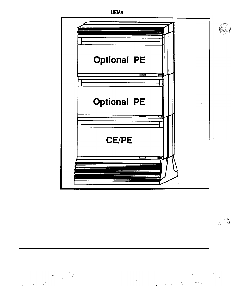
1-2 System organization
Figure l-l
Option 21 with multiple UEMs
553-3022
System engineering 553-3001-151
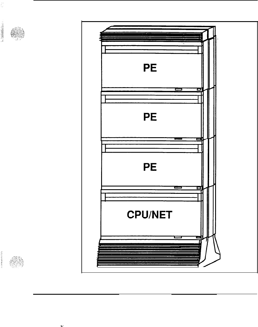
System organization 1-3
Figure 1-2
Option 51 with half network group
553-3023
System engineering 553-3001-l 51
.4
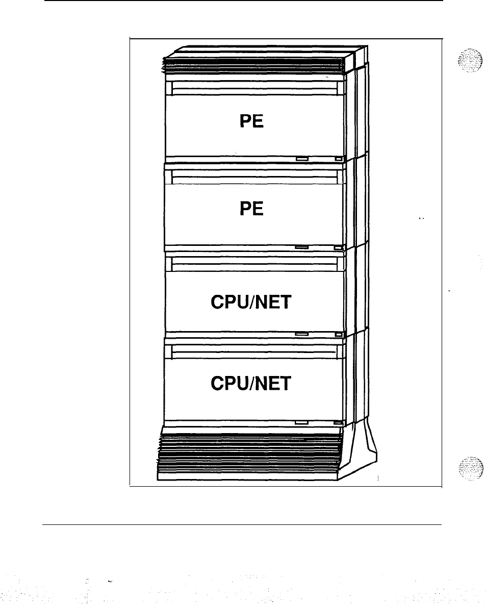
1-4 System organization
Figure 1-3
Option 61 with full network group
553-3024
System engineering 553-3001-151
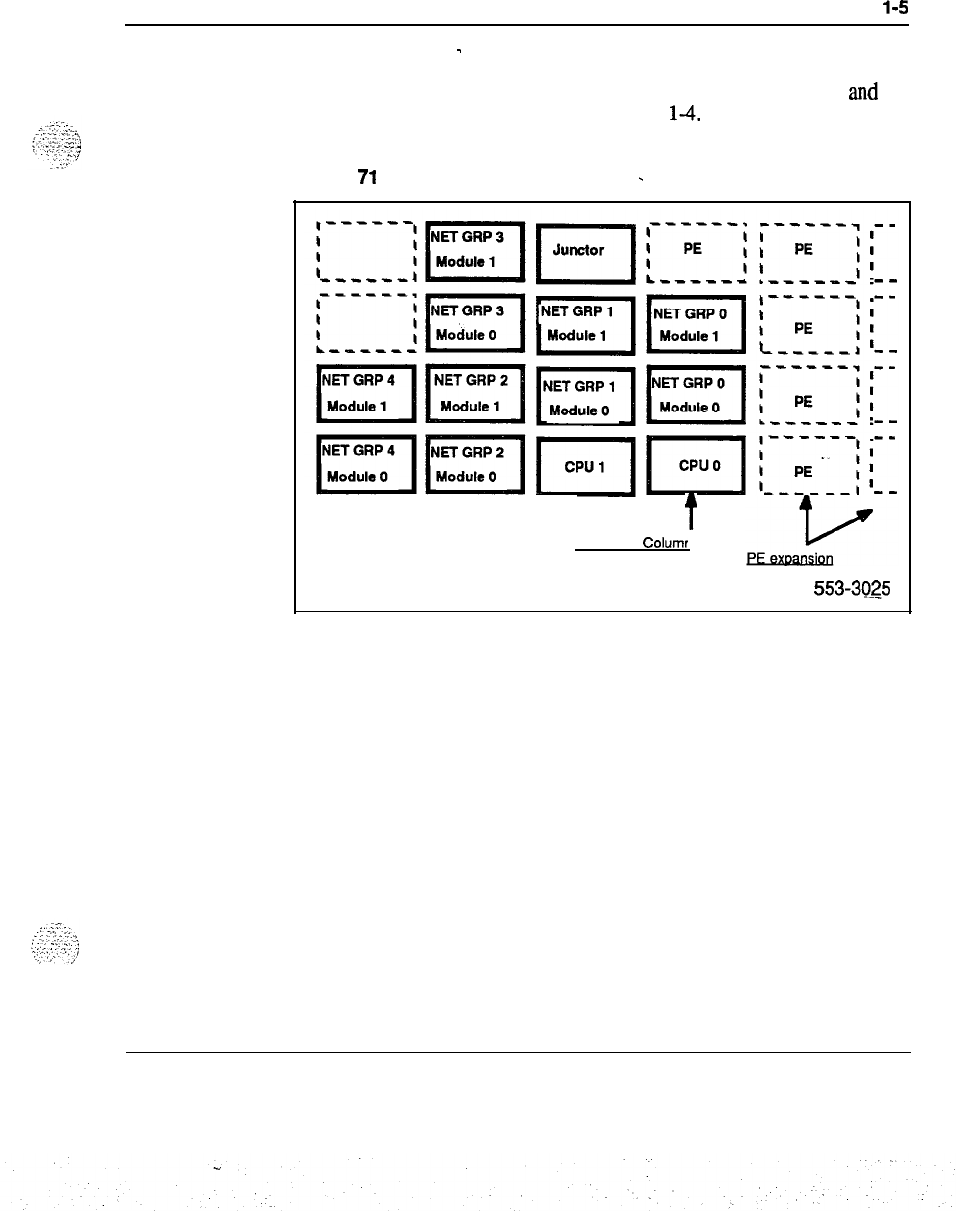
System organization
l-5
Option 71
-
Option 71 is a multiple network group machine with redundant
CPU
and
serves from 2,000 to 10,000 lines. See Figure
14.
Figure 1-4
Option
71
with multiple network group
-
t
Main UEM Columr
553-3025
Note:
This document has been updated to include new naming
conventions. Acronyms and abbreviations for the new names are
identified in the text using parentheses.
System engineering 553-3001-151
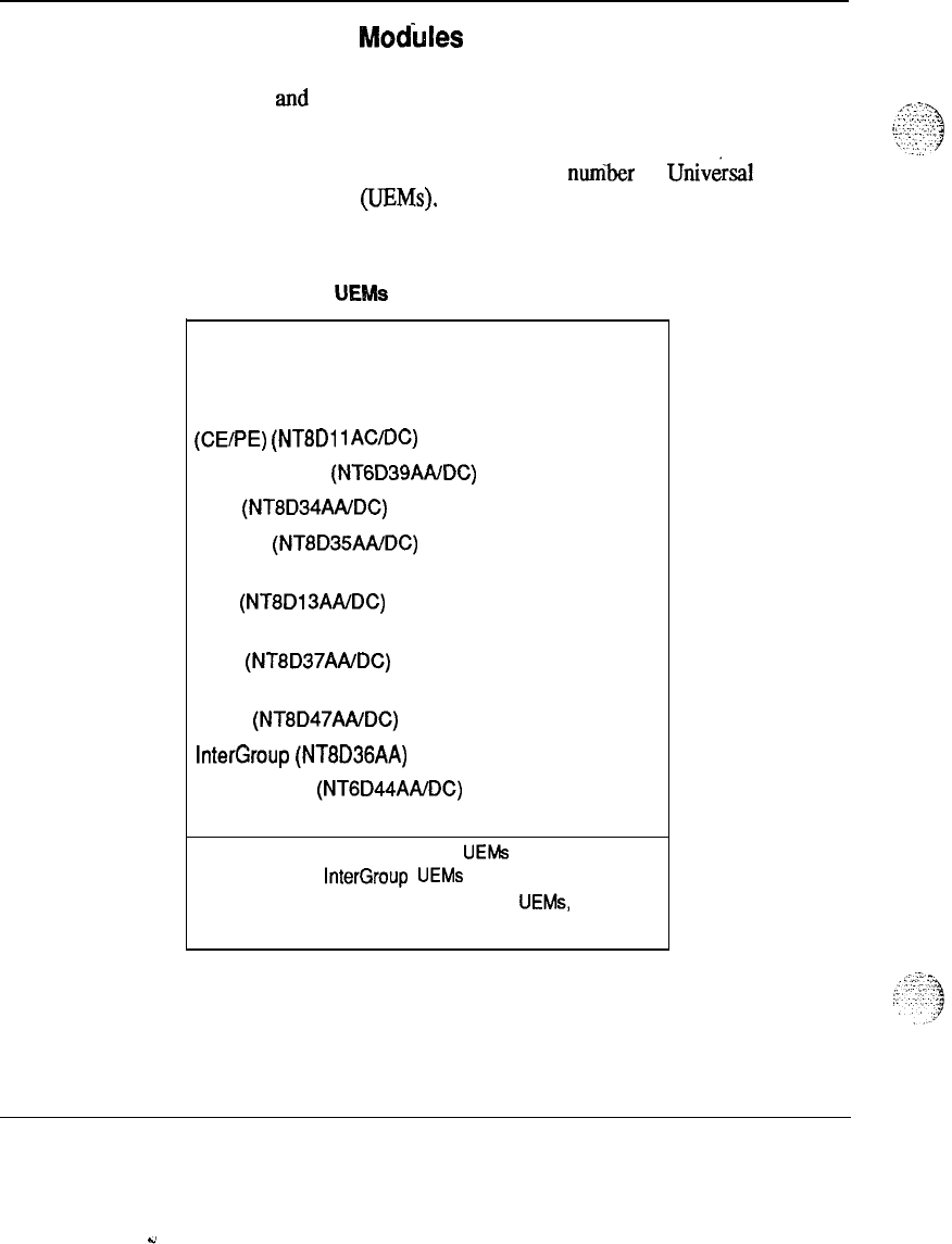
1-6 System organization
Universal Equipment Modtiles
This document has been updated to include new naming conventions.
Acronyms and abbreviations for the new names are identified in the text
using parentheses.
Each configuration of the SL-1 consists of a
nuniir
of
Univ&sal
Equipment Modules (UEMs). Each module can be identified by its
function. There are nine different types of UEMS:
Table l-1
Identification of UEMs
Universal Equipment Module Number required
per system
Common/Peripheral Equipment 1
(CE/PE)
(NT8Dl
lAC/DC)
CPU/Network
(NTGD39AA/DC)
1
CPU
(NT8D34AA/DC) 2
Network
(NT8D35AAIDC) 2 (see note)
Peripheral Equipment depends on
(PE)
(NT8D13AAIDC) system size
Intelligent Peripheral Equipment depends on
(IPE)
(NTBD37AAIDC) system size
Remote Peripheral Equipment depends on
(RPE)
(NT8D47AA/DC) system size
InterGroup
(NT8D36AA) 1 (see note)
Meridian Mail
(NTGD44AADC)
Optional
Note: In Option 61, two network UEMs are required per
network group; InterGroup UEMs are required in SL-1
Option 61 only. For more information on UEMs, refer to
Equipment identification and ordering (553-3001-l 54).
System engineering 553-3001-151
-,
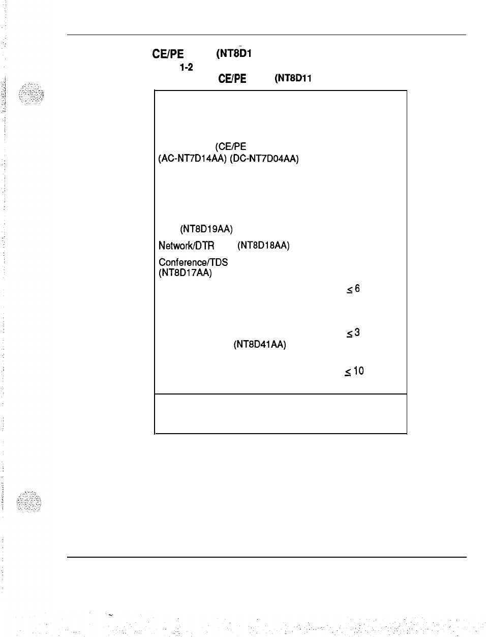
System organization 1-7
CUPE
UEM
(NT8h
1 AC/DC)
Table
l-2
Identification of
CUPE
UEM (NTBDll AC/DC)
Unit Number required
per UEM
Common/Peripheral Equipment
1
Power Supply (CE/PE Pwr Sup)
(AC-NT7D14AA)
(DC-NT7D04AA)
Floppy Disk Interface card (FDI)
1
(QPC742)
CPU card (QPC687)
1
Memory/Peripheral Signalling
1
card
(NT8D19AA)
NetworkDTR
card
(NT8D18AA)
1
ConferenceffDS
card
1
(NT8Dl7AA)
Network cards
16
Enhanced Serial Data Interface
(ESDI)
Serial Data Interface Paddle
53
Board (Dual Port)
(NT8D41AA)
supporting 6 SDI ports
Peripheral Equipment Line Cards
SlO
Note: This document has been updated to include new naming
conventions. Acronyms and abbreviations for the new names are
identified in the text using parentheses.
System engineering 553-3001-151
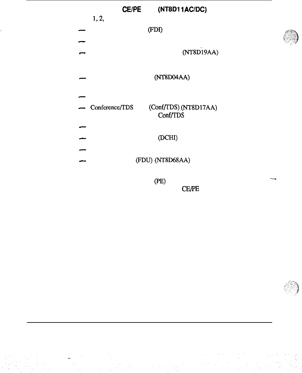
1-8 System organization
Description of CE/PE UEM (NT8Dl
lAC/DC)
Slots
1,2,
and 3 are reserved for the following circuit cards:
:
-
Floppy Disk Interface (FDI) (QPC742)
-
Central Processing Unit (CPU) (QPC687)
-
Memory/Peripheral Signalling Card (NT8D19AA)
Slots 4 through 9 in the Network area can be used by the following cards:
-
Superloop Network Card (lVlXDO4AA) serves one superloop (four
loops).
-
Enhanced Network Card (QPC4 14) serves two loops.
-
Conference/IDS Card (Conf/rDS) (NTSD17AA) uses two loops in the
Network area; at least one ConfR’DS is required in the system.
-
Digital Trunk Interface Card (DTI) (QPC472) occupies two slots.
-
D-Channel Interface Card @CHI) (QPC757)
-
Quad Serial Data Interface Card (QSDI) (QPC84 1)
-
Floppy Disk Unit (FDU) (NT8D68AA)
Note:
FDU occupies two slots and resides either in Network slots 4-9
or Peripheral Equipment (PE) slots O-9, depending on slot availability.
---
If all slots in the first column of the CE/PE UEM are occupied, FDU
can reside in the second PE module.
System engineering
553-3001-151
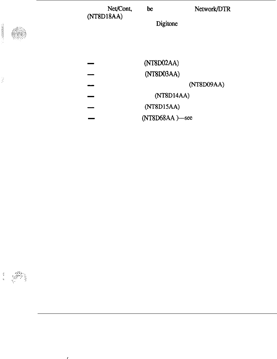
System organization 1-9
Slot 10, Net/Corn, must be occupied by the Network/DTR card
(NTSDlSAA) which combines the functions of a Network and Peripheral
Equipment controller and a Digitone receiver. The card provides ten loops
for ten PE cards.
Peripheral Equipment slots 0 through 9 can be occupied by any of the
following cards:
-
Digital Line Card
(NTSDO2AA)
-
Analog Line Card (NT8DO3AA)
-
Analog Message Waiting Line Card (NTSDO9AA)
-
Universal Trunk Card (NTSD14AA)
-
E&M Trunk Card (NTSDISAA)
-
Floppy Disk Unit (NTSD68AA
)-see
note above
.j
..I’:..
,,....
(
I
,
.__
:.
i
-’
.’
‘;
:
.,
.,
,.
System engineering 553-3001-l 51
,
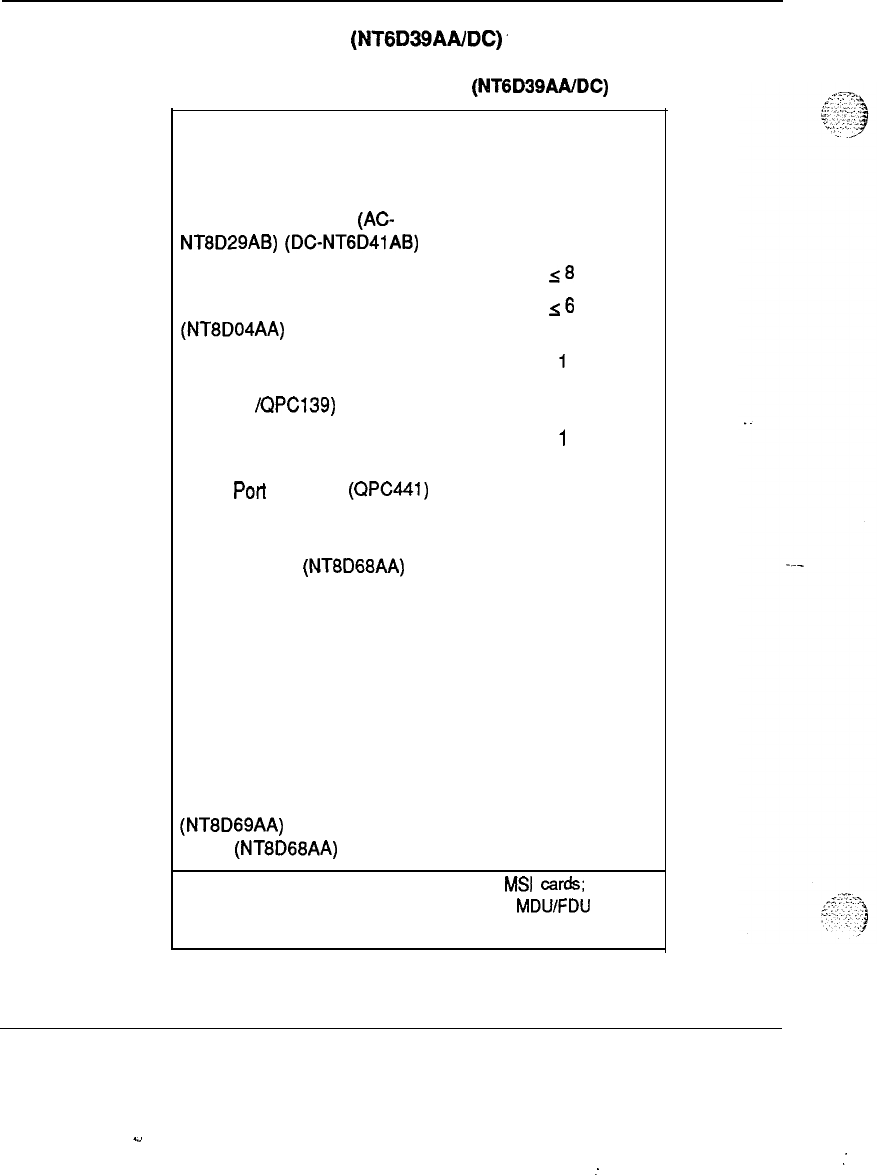
l-1 0 System organization
CPU/Network UEM
(NTGD39AAIDC)’
Table 1-3
Identification of CPU/Network UEM (NTGD39AAIDC)
Unit Number-required
per UEM
Common Equipment Power
1
Supply (CE Pwr Sup)
(AC-
NT8D29AB)
(DC-NTGD41AB)
Network cards (QPC414)
18
Superloop Network cards
~6
(NT8D04AA)
Clock Controller/Serial Data
1
Interface (SDI)
(QPC471 /QPC139)
Peripheral Signalling card
1
(QPC43)
Three
Port
Extender
(QPC441)
1
Mass Storage interface (MSI)
1
(QPC584) or Floppy Disk
Interface (FDI)
(NT8D68AA)
CPU Function card (QPC579)
1
CPU Interface card (QPC580)
1
Changeover and Memory
1
Arbitrator (CMA) card (QPC581)
768K Memory card (QPC583)
1
Serial Data Interface (SDI) card
1
(QPC139)
Multi-Drive Unit (MDU)
1
(NT8D69AA)
or Floppy Disk Unit
(FDU)
(NT8D68AA)
Note: The Multi-Disk Unit (MDU) requires MSI cards; the
Floppy Disk Unit (FDU) requires FDI cards. MDU/FDU
occupies two slots.
System engineering 553-3001-151
.4
:
:
System organization
l-11
Description of CPWNetwork UEM (NTGD39AAiDC)
Slots 1 through 8 are reserved for the following cards:
-
Network cards (QPC4 14 or NT8DO4AA)
The rest of the slots contain the following cards:
-
slot 9 : Clock Controller or Serial Data Interface (SDI)
-
slot 10: Peripheral Signaling
-
slot 11: Three Port Extender (3PE)
-
slot 12: Mass Storage Interface (MSI)
-
slot 13: SD1
-
slot 14: CPU function
-
slot 15: CPU interface
-
slot 16: Changeover and Memory Arbitrator (CMA)
-
slot 17: Memory
Note:
This document has been updated to include new naming
conventions. Acronyms and abbreviations for the new names are
identified in the text using parentheses.
System engineering 553-3001-l 51
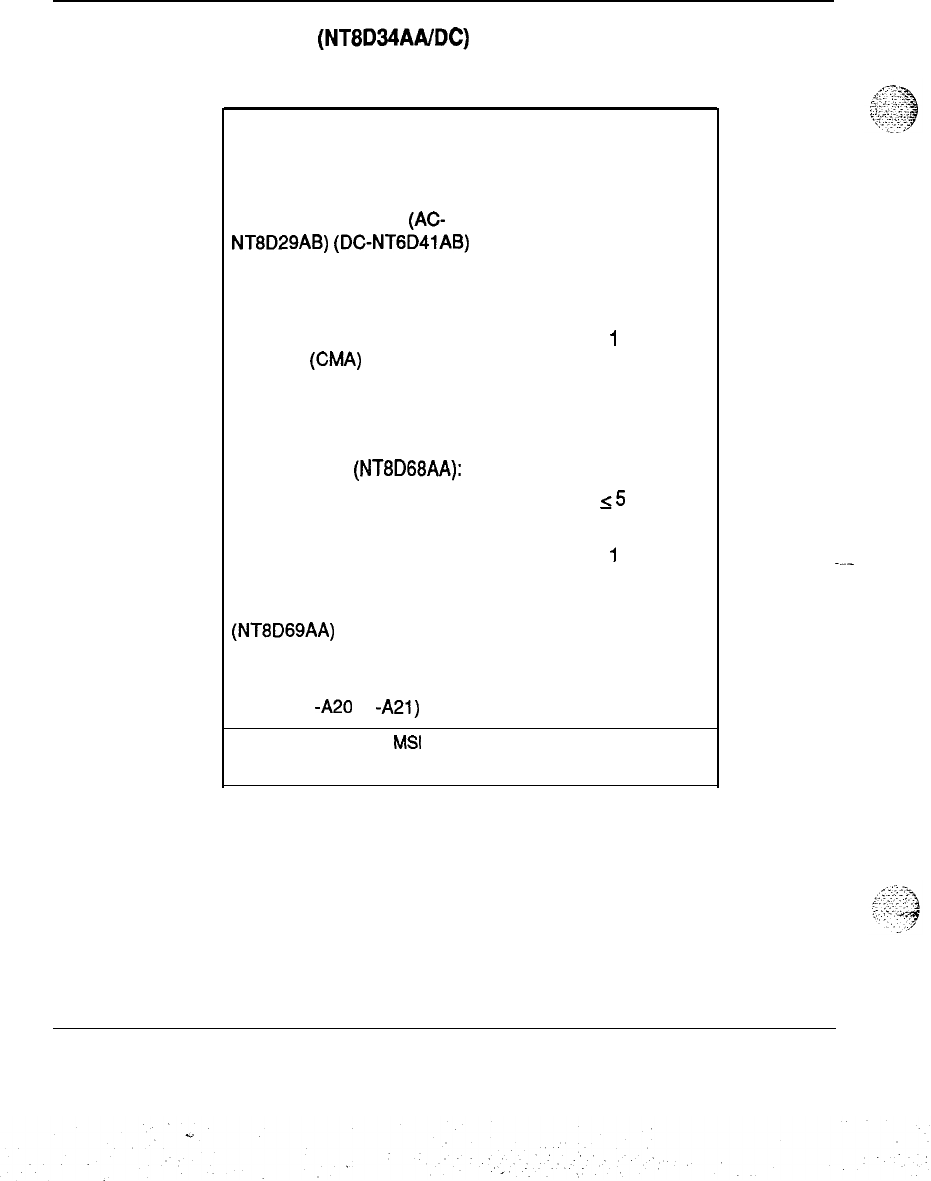
l-l 2 System organization
CPU UEM
(NT8D34AAIDC)
Table l-4
Identification of Single CPU UEM
Unit Number- required
per UEM
Common Equipment Power
1
Supply (CE Pwr Sup)
(AC-
NT8D29AB)
(DGNTGD41AB)
CPU function card (QPC579)
1
CPU interface card (QPC580)
1
Changeover and Memory
1
Arbitrator
(WA)
card (QPC581)
Memory cards (QPC583) 2
Mass Storage Interface card
1
(MSI) (QPC584) or Floppy Disk
interface (FDI)
(NT8D68AA):
Segmented Bus Extender (SBE)
15
cards (QPC215)
Clock Controller card (QPC471 or
I
QPC775 international)
Multi-Drive Unit (MDU)
1
(NT8D69AA) or one DTI (Digital
Trunk Interface) card (QPC742)
Bus Terminating Unit (BTU)
2
(QPC477
-A20
or
-A21)
Note: MDU
requires
MS.1
cards;
FDU
requires
FDI cards; MDU
occupies three
slots
in the
UEM, FDI
occupies two.
System engineering 553-3001-151
System organization 1-13
Description of CPU UEM (NT8434AAIDC)
Slots l-2 are reserved for the following cards:
-
Memory cards (QPC581)
The rest of the slots contain the following
c-ards:
-
slot 3: CMA
-
slot 4: CPU interface
-
slot 5: CPU function
-
slot 6:
SD1
-
slot 7: MS1
-
slots 8-12: Segmented Bus Extender (SBE)
-
slot 13: available
slot 14: Clock Controller
_.
-
-
slot 15: Mass Storage Unit (MSU) or Floppy Disk Unit (PDU), or
Primary Rate Interface (PRI)/Digital Trunk Interface (DTI)
Note:
This document has been updated to include new naming
conventions. Acronyms and abbreviations for the new names are
---
identified in the text using parentheses.
System engineering 553-3001-l 51
<,
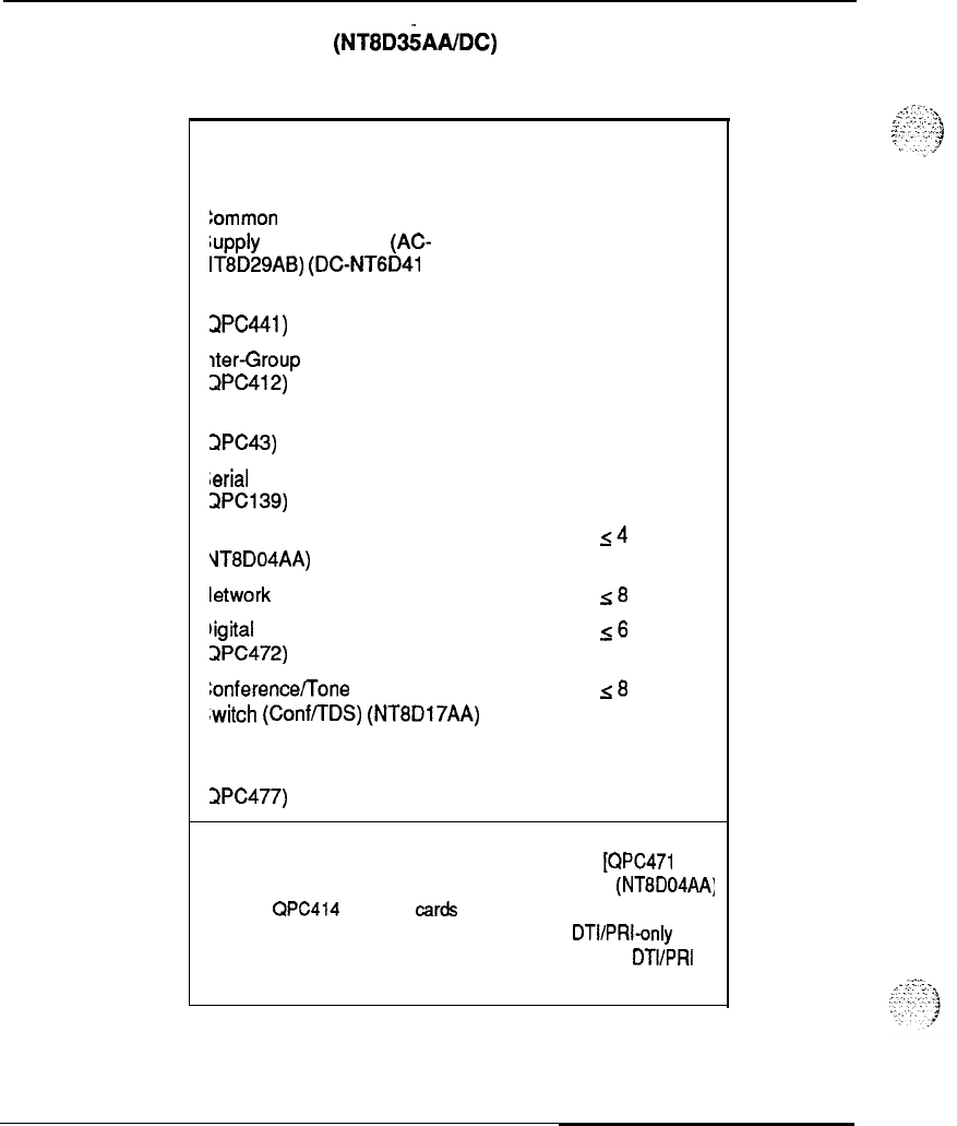
l-1 4 System organization
Network UEM
(NT8D%AA/DC)
Table l-5
Identification of Network UEM
hit
Number_ required
per UEM
:ommon Equipment Power
1
upply
(CE Pwr Sup)
(AC-
IT8D29AB)
(DCNTGD41
AB)
‘hree-Port Extender (3PE)
1
slPC4.41)
Iter-Group
Switch (IGS) cards 2
ZPC412)
‘eripheral Signalling card
1
3PC43)
#erial
Data Interface (SDI) card
1
zlPCl39)
uperloop Network cards
14
‘JT8D04AA)
letwork cards (QPC414)
s8
rigital
Trunk Interface (DTI)
16
JPC472) cards
LonferencefTone and Digit
~8
‘witch
(Conf/TDS)
(NT8D17AA)
ards
us Terminating Units (BTU)
JPC477) 2
Note: IGS cards are for Option 71 only. In Options 51 and 61,
these slots are occupied by Clock Controller Cards fQPC471
B or
higher vintage].) The four Superloop Network cards
(NTBD04AA;
or
eight QPC414 Network cards can be configured in any
combination for a total of 16 loops. Also, as a
DTVPRI-only
UEM
Network UEM contains one CE Pwr Sup and up to six
DTVPRI
cards.
System engineering 553-3001-151
. .
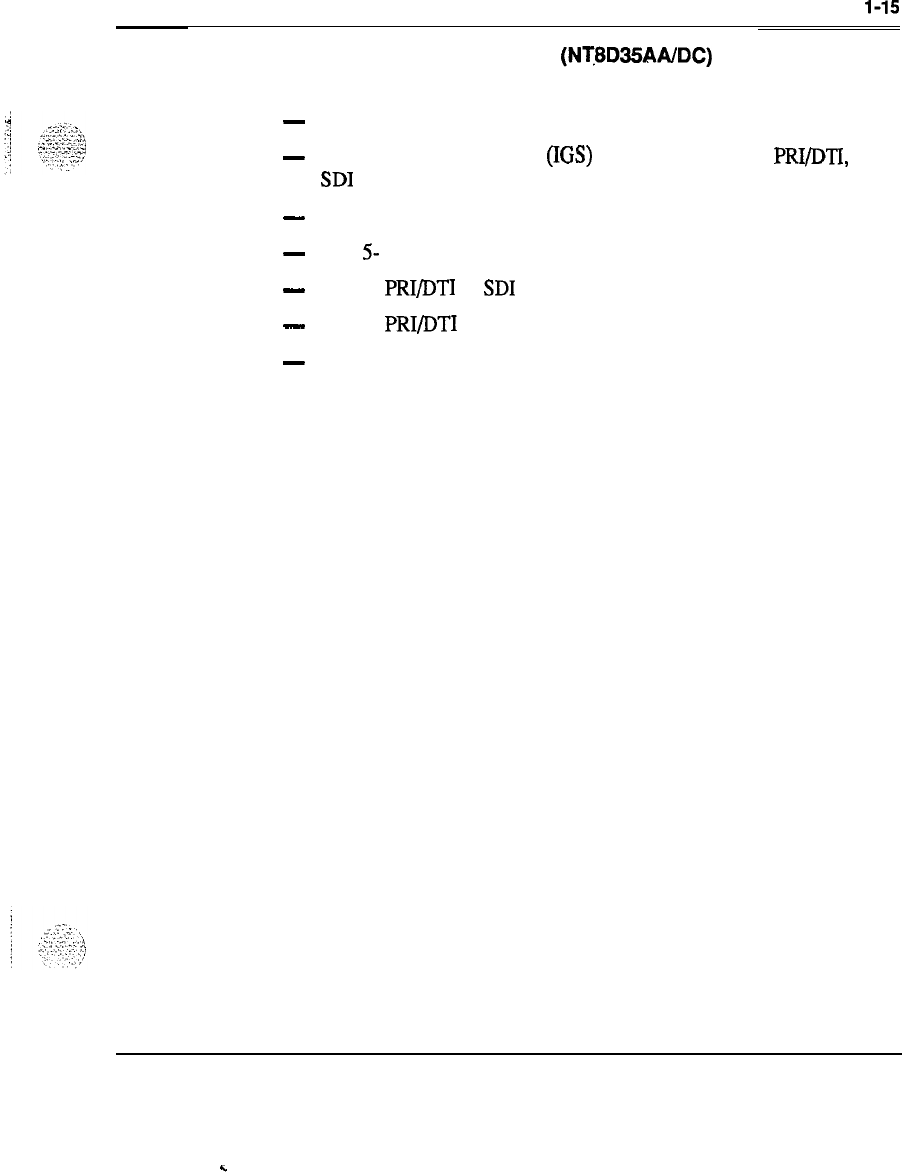
System organization
l-15
Description of Network UEM (NT8D35AAIDC)
The slot assignment of cards is as follows:
-
slots 1: Three Port Extender (3PE)
-
slots 2-3: Intergroup Switch (IGS) (for Option 71 only), PRI/DTI, or
SD1
-
slot 4: Peripheral signaling
-
slots 5- 12: Network cards
-
slot 13: PRI/DTI or
SD1
-
slot 14: PRI/DTI
-
slot 15: not used
Note:
This document has been updated to include new naming
conventions. Acronyms and abbreviations for the new names are
identified in the text using parentheses.
. .
System engineering 553-3001-151
.
.
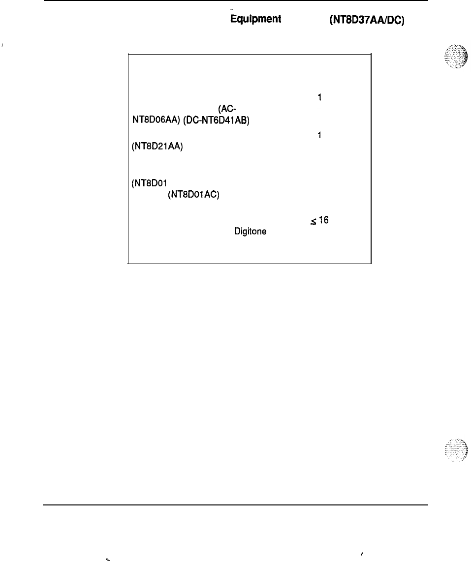
l-1 6 System organization
Intelligent Peripheral
&ipment
UEM (IPE)
(NT8D37AAlDC)
Table l-6
Identification of IPE UEM
Unit Number required
per UEM
Peripheral Equipment Power
Supply (PE Pwr Sup)
(AC-
NT8DOGAA)
(DC-NTGD41AB)
AC Ringing Generator
(NT8D21AA)
(required only when
analog cards are present)
Controller-2 (Cont-2)
(NT8DOl AD) Card or Controller-4
(Cont-4)
(NT8DOlAC)
Card (See
note.)
1
Line cards or a combination of
analog, digital, trunk, and Digitone
receiver cards (Table l-7 shows
the port-to-line card orientation.
~16
System engineering 553-3001-151
I
-2
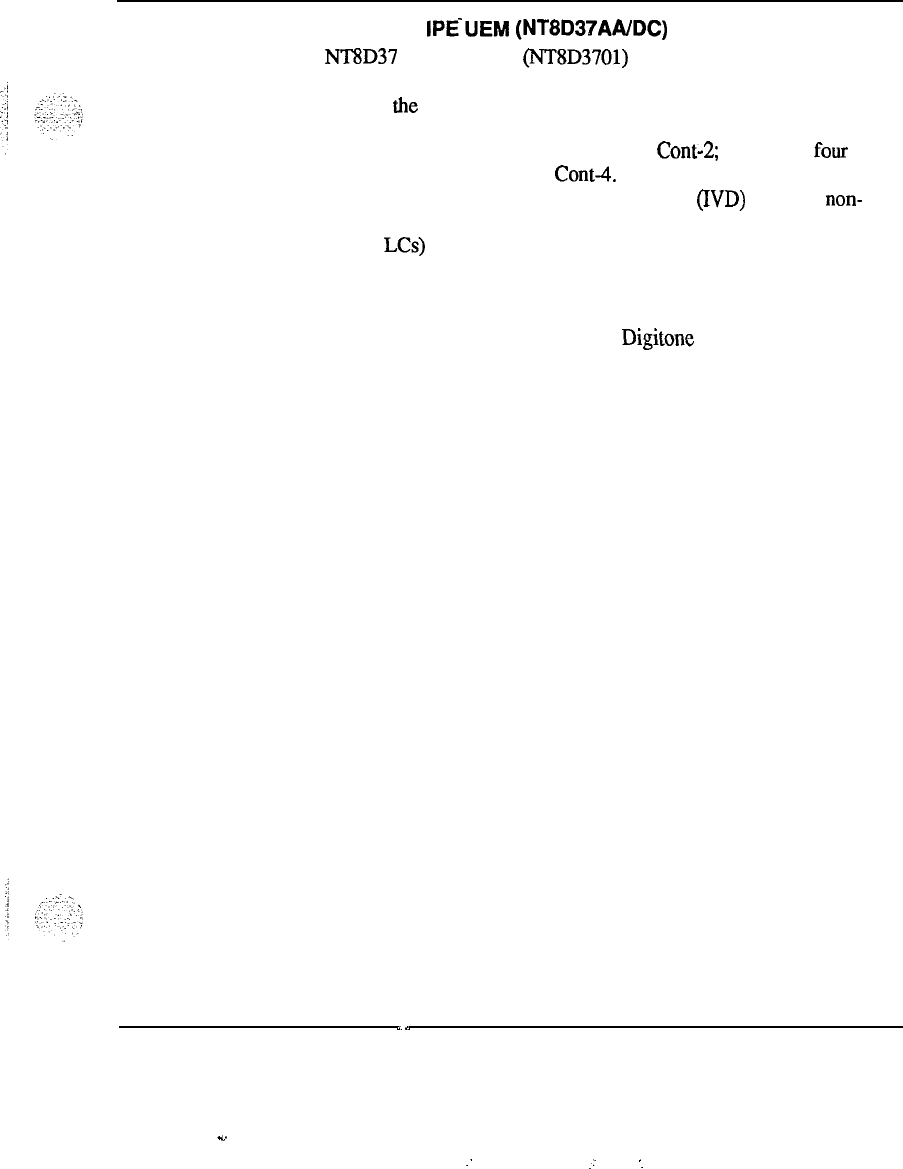
System organization 1-17
Description of
IPE‘UEM
(NT8D37AA/DC)
The NT8D37 IPE backplane (NT8D3701) contains 16 card slots. Slots O-15
are for line cards. Slot 16 is for miscellaneous. The Controller Card is
situated near the center of the module, between slot 7 and slot 8.
If one or two superloops are to be served, use
Cont-3
If three or four
superloops are to be served, use Cant-4. The Controller-4 card is required
when a large number of Integrated Voice and Date
(ND)
lines are non-
blocking and when they require, on average, more than four Digital Line
Cards (Dgtl LCs) per IPE DEM.
The nominal capacity.of the IPE UEM is 256 Integrated Voice and Data
(IVD) or analog lines; however, a typical configuration of the PE UEM
includes a combination of line, trunk, and
Digitone
Receiver cards which
provide about 160 lines with the appropriate trunks.
System engineering 553-3001-l 51
.s..
-.
.:
‘.
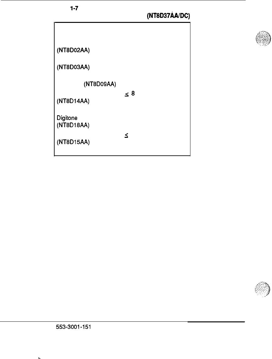
l-1 8 System organization
Table
l-7
Port-to-line card orientation for IPE
(NT8D37hUDC)
line cards
Line card Ports served
Digital Line Card 16 Digital
(NT8D02AA)
Analog Line Card 16 Analog
(NTBD08AA)
Analog Message Waiting 16 Analog with Message
Line Card (NT8DOSAA) Waiting features
Universal Trunk Card
ZG
8 trunks with
any
(NT8D14AA) combination of
CO/DID/RAN/Page
Digitone
Receiver Card
8 channels of DTMF or
(NT8D18AA) MF receivers
E&M Trunk Card
I
4 trunks with any
(NT8Dl5AA)
combination of
E&M/Page trunks
System engineering
553-3001-151
.
.
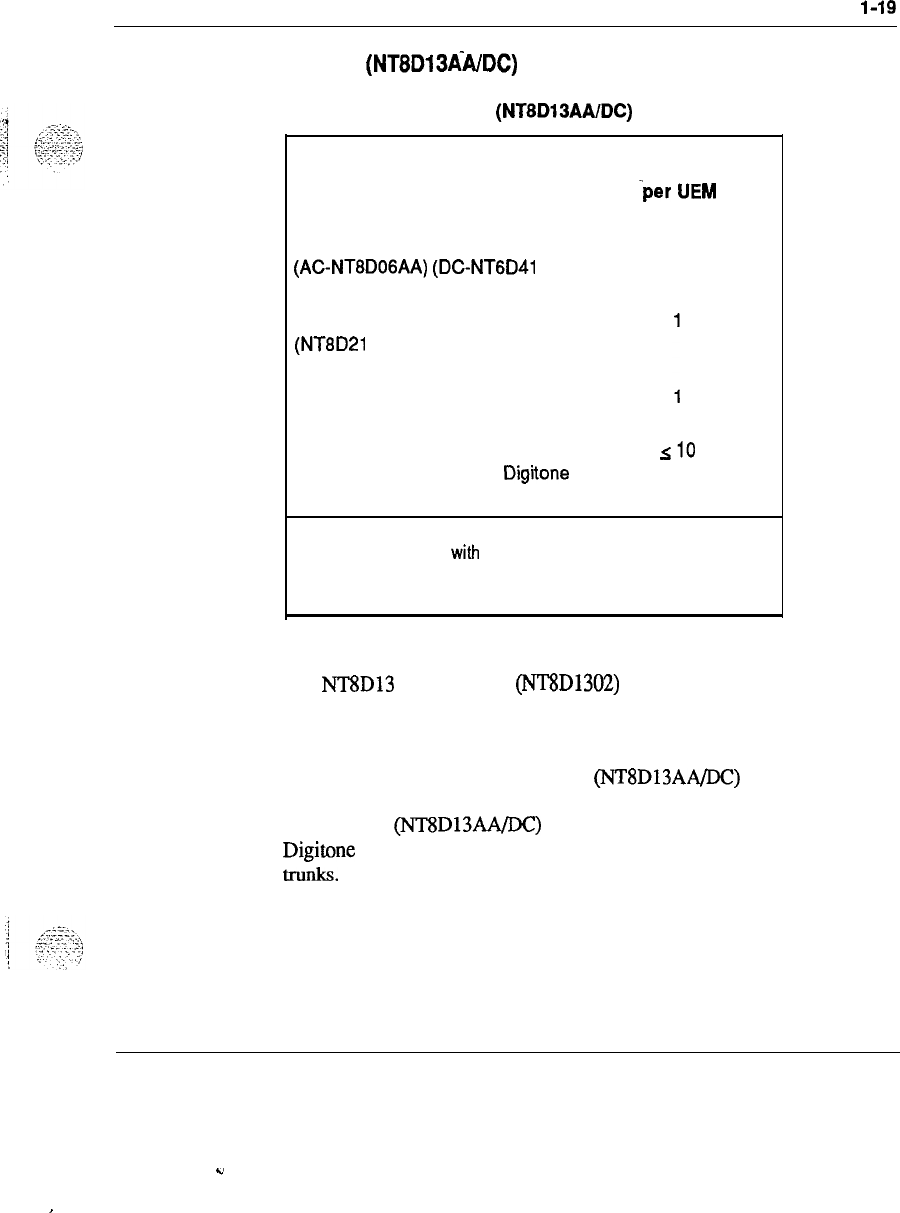
System organization
l-19
PE UEM
(NT8D13&DC)
Table l-8
Identification of PE UEM (NTBD13AAIDC)
Unit Number required .
-per
UEM
Peripheral Equipment Power
Supply (PE Pwr Sup)
(AC-NTBDOGAA)
(DC-NTGD41
AB)
See note.
1
AC Ringing Generator (Rng Gen)
(NT8D21 AA) (required only when
analog cards are present.)
Dual Loop Peripheral Equipment
Buffer (QPC659)
Line cards or a combination of
analog, digital, trunk, and Digitone
receiver cards
silo
Note: QPC710 DTR can be
used if required by the customer; If
QPC710 DTR is
used with a single loop on the
QPC659,
then
slot 10 cannot be used. Both AC and DC versions of PEPS are
available.
The NT8D13 PE backplane (NT8D1302) contains 10 line card positions.
The PE Buffer is situated near the center of the module, with five line cards
to the left and five line cards to the right.
The nominal capacity of the PE UEM (NT8D13AA/DC) is 160 Integrated
Voice and Data (IVD) or analog lines; however, a typical configuration of
the PE UEM (NT8D13AA/DC) includes a combination of line, trunk, and
Digitone
Receiver cards which provide about 100 lines with the appropriate
tnmks.
System engineering 553-3001-l 51
‘..
,
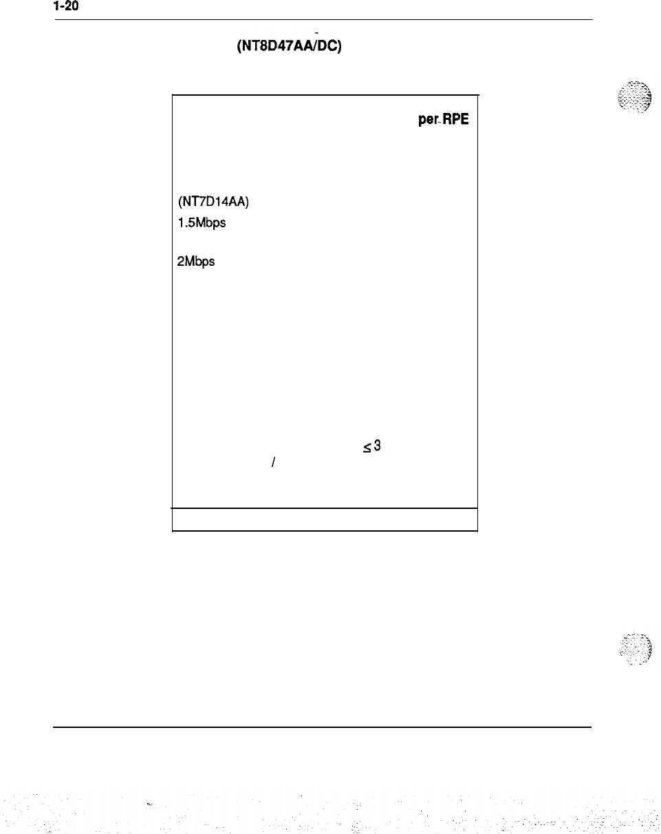
l-20
System organization
RPE UEM
(NTBD47AtiDC)
Table l-9
identification of RPE UEM
Unit Number Number
per UEM
perJtPE
loop
Common/Peripheral
1
Equipment Power Supply
(CPE Pwr Sup)
(NT7D14AA)
1.5Mbps Converter cards 2
1
(QPC62)
2Mbp.s Converter cards 2
1
(QPC66)
Carrier Interface cards 2
1
(QPC99)
Local Carrier Buffer 2
1
(QPC63)
Remote Peripheral Buffer 2
1
(QPC65)
Carrier Maintenance card
1
1
(QPC67)
Digital Trunk Interface
s3
cards (QPC472)
/
Primary
Rate Interface (PRI)
(QPC720)
Note: Each RPE UEM can
support up
to two RPE
loops.
System engineering 553-3001-151

System organization
1-21
Description of RPE UEM
The slot assignment of cards is as follows:
-
slot 1:
PRI/DTI
(optional)
-
slot 2: 1.5 Mb converter
-
slot 3: 2 Mb converter
-
slot 4: carrier interface
-
slot 5: remote peripheral
-
slot 6: local carrier buffer
-
slot 7: carrier interface
-
slot 8: 2 Mb converter
-
slot 9: 1.5 Mb converter
-
slot 10: carrier maintenance
-
slots 11-12:
PRI/DTI
(optional)
The minimum configuration for RPE consists of an RPE UEM at the main
PBX site and the following equipment at the remote site:
-
one RPE UEM
(NT8D47AALDC)
-
one PE UEM (NT8D13AA/DC)
-
one pedestal
-
one top cover
The engineering rules for RPE UEM are the same as for the existing RPE
shelf except there are three 2” slots available for DTI/PRI Cards in the RPE
UEM.
1
.A-:,.
i
;:.
:
:I:::
:::
‘1
.
..<
.
.
.,
:
.:.
.,;-..
,,
System engineering 553-3001-l 51
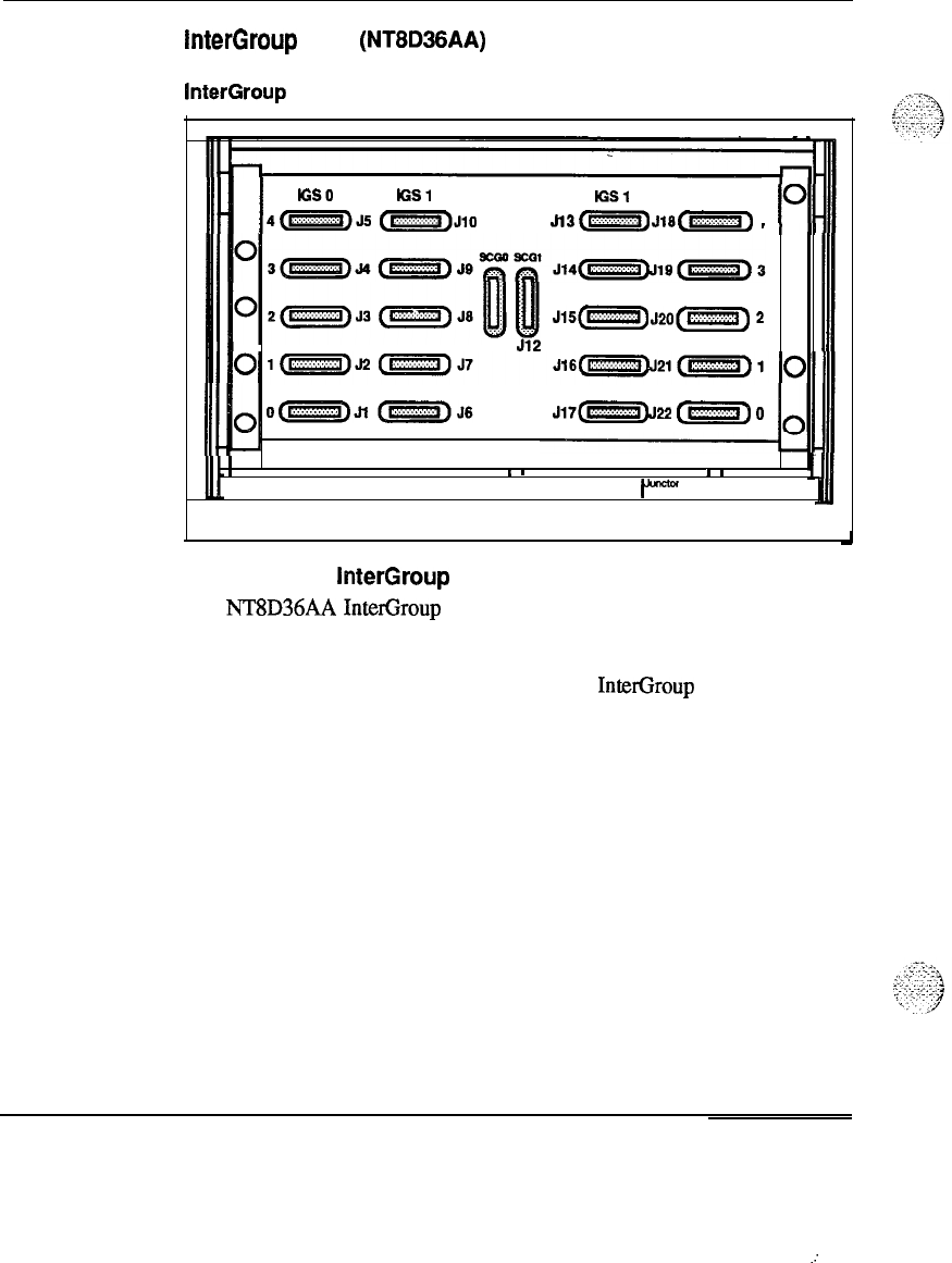
1-22 System organization
InterGroup UEM (NT8D36AA)
Figure l-5
InterGroup UEM
0
III-I
I
IGSO
Ial
IGSl
IGS 0
4(m)&
(m)Jqo
J,3
(m>
Jlacm)
4
0
J15(-)
J*‘,(w)
2
0
Jll
512
II--
0
J17c~3~
c”““)
0
I
I
I
I
II
553-3026
Description of InterGroup UEM
The NT8D36AA InterGroup UEM provides a path for the switching of
---
traffic between the network groups in the system. Faceplate cables from the
Segmented Bus Extender (SBE), System Clock (SCG), and Intergroup
Switch (IGS) circuit cards are connected to the InterGroup Module.
System engineering 553-3001-151
. .
.:
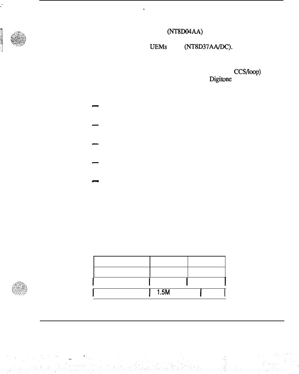
System organization 1-23
.’
System capacities
-
Network terminating capacity
The Superloop Network Card (NT8DO4AA) has four network loops
grouped as one superloop. One superloop can serve up to, two Intelligent
Peripheral Equipment
UEMs
(IPE)
(NT8D37AA/DC).
Network traffic capacity
Each superloop is capable of carrying 3500 CCS (or 875 CCS/Ioop) of
combined station, trunk, attendant console and
Digitone
traffic during
Average Busy Season Busy Hour (ABSBH) subject to the following grades
of service:
-
the loss of no more than 1% of the incoming terminating calls, provided
the called line is free
-
the loss of no more than 1% of the originating outgoing calls in the
system, provided an idle trunk is available
.
-
the loss of no more than 4% of the intra-office calls, provided that the
called line is free
-
no more than 1.5% of the originating calls wait longer than 3 seconds
for dial tone
-
the loss of no more than 1% of tandem calls, provided an idle outgoing
trunk is available
Memory capacity
The memory capacity is a function of the machine type. Memory
requirements are a function of the system size and features available. See
Table l-10 for the memory capacities of each system:
Table l-10
Memory capacity per system
System Memory
Option 21 768K words
Mbytes
1.5
1
Options 51 and 61 1 768K words
1
2.3
I
Option 71
1
1.5M
words
1
4.5
I
System engineering 553-3001-l 51

1-24
System organization
Configuration capacities
The maximum configuration capacities of the SL-1 Options
51,61,
and 71
are:
-
100 customers
-
30 steps in a hunting group
-
8191 speed call lists per system
-
4095 ringing number pickup groups per customer
-
5 12 trunk routes per customer
-
254 members per trunk route
-
4 listed directory numbers per customer (DID only)
-
1 lamp field array per customer, may be repeated once on other console
or SL-1 set
-
150 lamps per array (all numbers to be consecutive)
-
63 consoles per customer (Release 8 and later releases)
-
10 feature keys per console
-
20 incoming call indicators per console
-
16 trunk group busy indicators per console
-
2 additional key/lamp strips per console
-
6 additional key/lamp strips per SL-1 set
-
16 input/output devices (TTY etc.)
-
30 appearances of the same directory number
A system may not be able to accommodate simultaneously all the maximum
values listed due to system limitations on the real time, memory, or traffic
capacity.
System engineering 553-3001-151
. .
.:.
..’
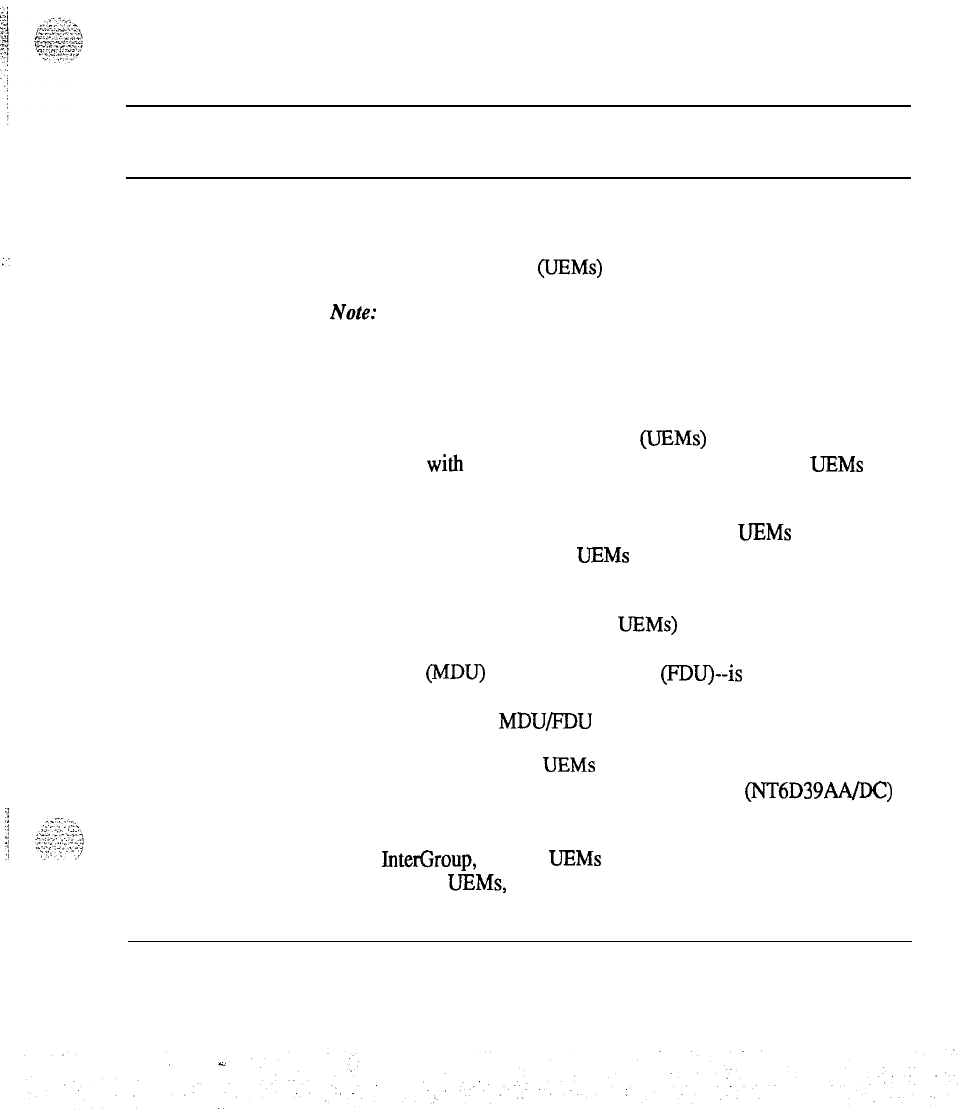
2-1
Definitions
General rules
Apply the following rules for system engineering when arranging various
Universal Equipment Modules (UEMs) within an SL- 1.
Note:
This document has been updated to include new naming
conventions. Acronyms and abbreviations for the new names are
identified in the text using parentheses.
UEM and column designations
Columns of Universal Equipment Modules (UEMs) are numbered from 0 to
63. The column with CPU 0 is Column 0. Within a column, the
UEMs
are
numbered as 0 to 3 starting from the bottom UEM.
A UEM column can be built up to a maximum of four
UEMs
before moving
to the next column; however, three UEMs per column can be configured if
it is easier for installation and maintenance.
All the SL-1 Common Equipment (CPU UFMs) must be at the bottom or
one level up for proper cooling and reliability. The mass storage unit--
Multi-Disk Unit (MDU) or Floppy Disk Unit (FDU)--is usually located in a
CPU UEM and requires lower operating temperatures than the cards. For
this reason, do not install MDU/FDU in the third or fourth UEM.
The Common Equipment (CE) UEMs must be located next to each other at
the same horizontal level. The CPU/Network Modules (NT6D39AA/DC)
(CNE) must be located on top of each other.
The CPU, InterGroup, and CE UEMs must be located in the same vertical
column. For these UEMs, all inter-UEM cabling must be internal, not
System engineering 553-3001-l 51
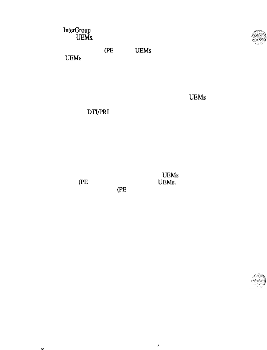
2-2 Definitions
through the I/O panels or EM1 filters. In addition, all vertical routing of the
internal signal cables should be done on the right side of a column.
The InterGroup UEM should be located at the top of a column and adjacent
to the CE UEMs.
Peripheral Equipment (PE or IPE) UEMs may be located away from CE and
CPU
UEMs
by a maximum network cable length of 45 feet. This means
that typically at floor level the CE UEM serving its PE cannot be more than
20
feet apart.
Configurations
A full network group consists of two half network group
UEMs
stacked one
on top of the other. This rule does not apply when the Network Module is
used only as a DTI/PRI shelf.
SL-1 Option 51 can be configured using one Network Module (half network
group) or two Network Modules (full network group). SL-1 Option 71 must
be expanded in increments of full network groups.
In multiple-group machines, the addition of network groups should be
considered in the floor plans. Make sure the network groups are located in
one contiguous equipment bay. One possibility is to provide space for
expanding network groups to the left of CPU
UEMs
and Peripheral
---
Equipment (PE or IPE) to the right of CPU UEMs. Another possibility is to
keep Peripheral Equipment (PE or IPE) expansion as a separate bay. See
Figure 14 “Option 71 with multiple network group.”
System engineering 553-3001-151
I
v
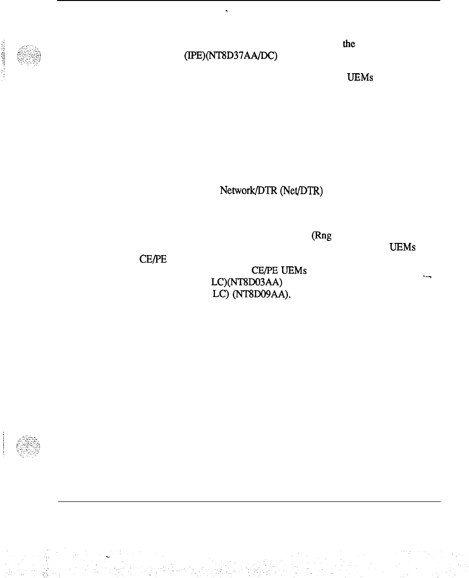
Definitions 2-3
Peripherals
-
One superloop (the equivalent of four regular loops) should serve two, four,
six, or eight segments. A segment is one-fourth of the Intelligent Peripheral
Equipment (IPE)(NT8D37AA/DC) shelf containing four slots.
A superloop can serve from one segment to two IPE
UEMs
in increments of
one segment, depending on the ratio of TN to TS. Preferably, a superloop
should be configured to serve an even number of segments. Assign full
traffic and IPE Cards to one superloop before assigning to the next.
For every superloop which has “empty” IPE slots associated with it
(because it is not assigned to exact multiples of eight cards), there should be
spare traffic to use those slots when the system grows. Future additions of
IPE Cards can be made to these superloops.
For traffic purposes, Network/DTR (Net/DTR) may be typically assigned to
serve 96 lines, 32 trunks, and 8 DTR ports (10 IPE Cards total ) even though
it has higher traffic capacity.
The total number of AC Ringing Generators (Rng Gen) in a system can be
minimized by consolidating all Analog Line Cards in a few IPE
UEMs
and
CE/PE UEM, if applicable. For traffic and reliability reasons, no more than
three-fourths of the IPE and CE/PE UEMs should be filled with Analog
Line Cards (Anlg LC)(NT8DO3AA) or Analog Message Waiting Line
---
cards (Anlg M/W LC) (NT8Do9AA).
Note:
This document has been updated to include new naming
conventions. Acronyms and abbreviations for the new names are
identified in the text using parentheses.
System engineering 553-3001-l 51
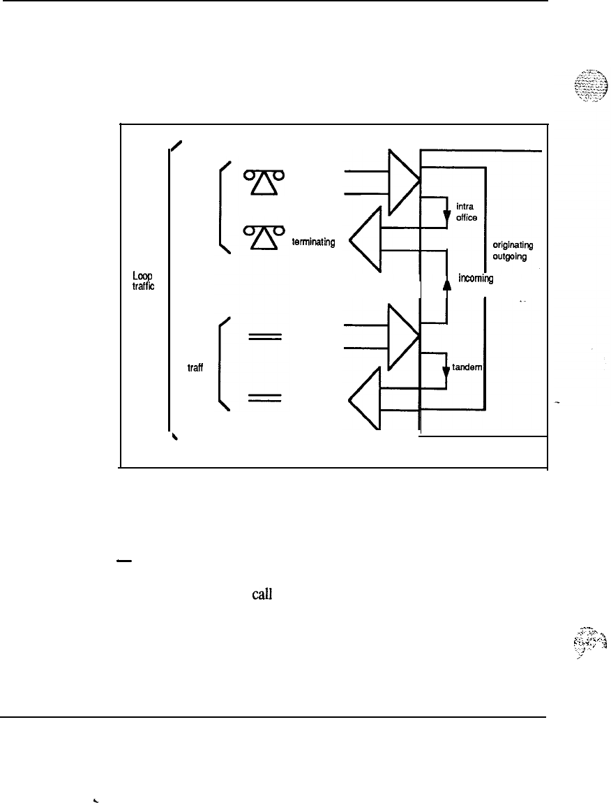
2-4 Definitions
Traffic distribution
-
The traffic distribution in the SL- 1 is
illustrated in
Figure 2-1. This
illustration is valid when considering individual customer or system traffic.
Figure 2-1
Traffic distribution over the SL-1
Loop
traffic
/
Line
traffic
Trunk
iraff ic
7Y
originating
terminating
incoming
outgoing
SL-1 System
homing
”
terminating
553-3027
Traffic definitions
The following are definitions of traffic terminology used in determining the
provisioning requirements of an SL-1 System:
-
ccs=
Hundred call seconds. The unit in which amounts of telephone traffic
are measured. One call which lasts for one hundred seconds equals one
ccs.
yn..
I::
:::.
:’
,:..
..,.
.I.
.
.._
. .
;,.:.
~,Z
,.
4
,+
System engineering 553-3001-151
.
.
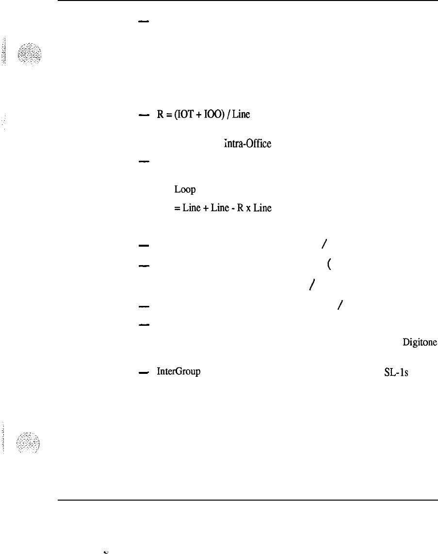
Definitions 2-5
-
Line=IT+OO+IOT+IOO
where:
Line
= Line traffic in CCS
IT = Incoming Terminating traffic in CCS.
00
= Originating Outgoing traffic in CCS
IOT = Irma-Office Terminating traffic in CCS
100
= Inn-a-Office Originating traffic in CCS
-
R=(IOT+IOO)/Line
where:
R= Irma-Office Ratio
-
Loop=Line+IT+OO
where:
Loop = loop traffic in CCS
=Line+Line-RxLine
= Line x (2-R)
-
Total line capacity = Total loop capacity
/
(2-R)
-
Total trunk capacity = Total line capacity x
(
1-R)
= Total loop capacity x (1-R)
/
(2-R)
-
Total I/O capacity = Total loop capacity x R
/
(2-R)
-
Network = Total CCS handled by the SL-1 switching network or:
= Traffic received from stations + trunks, attendants, Digitone
receivers, conference circuits and special features.
-
InterGroup = Traffic flow between two network groups in SL-1s having
more than one network group.
System engineering 553-3001-l 51
2,
2-6 Definitions
Equipment utilization
Equipment is provided and maintained throughout the SL-1 location life at
an 85% utilization level.
Network loop traffic
The recommended traffic level for a Network superloop is:
-
3500 CCS without Digitone-using apparatus
-
2975 CCS with Digitone-using apparatus
The traffic level per netwcrk loops depends on whether or not the Peripheral
Equipment uses Digitone trunks.
Partitioning
The SL-1 can be configured as a partitioned or non-partitioned system when
it is to serve more than one customer.
.
A partitioned system dedicates each customer and the customer’s associated
lines and trunks to actual partitioned segments of the system in terms of
loops and shelves. Consoles and Digitone receivers are normally spread
over all loops and shelves in a partitioned system.
In a non-partitioned system, all customers, trunks, lines, consoles, and
Digitone
receivers are spread over all loops and shelves. A non-partitioned
system provides the following advantages:
-
fewer traffic loops are required
-
fewer PE shelves and cards are required
-
system call-carrying capacity is more easily achieved and maintained
-
customers are distributed evenly over the loops
-
load balancing is more easily accomplished by being done on a system
basis rather than for each customer
System engineering 553-3001-151
Definitions 2-7
Network loop assigning
When assigning the loop number in systems equipped with two Network
UEMs, the load should be distributed evenly across both UEMs. Loops
should be assigned in the order shown in Table 2- 1. Record the loops used
.
in Worksheet L provided at the end of this document.
The total number of Peripheral Equipment
UEMs
should be distributed over
the total number of voice and data loops. Normally, one PE UEM is
assigned to a superloop. However, one PE UEM
cart
be assigned from one
half-superloop to as many as four superloops, depending on the
concentration of Terminal Numbers to Timeslot ratio. See Table 2-l for
details on loop number assignments.
Total number of loops = 4 x No. of Superloop Network Cards + 2 x No. of
3nhanced Network Cards
rable 2-1
,oop number assignment
Number of groups Number of loops
1
28
256
384
4112
5140
Note: The assignments shown may vary
depending on system configuration and size.
Conference (CONF) and Tone and Digit Switch
(TDS) may be assigned any even loop number.
Do not assign the odd loop number associated
with CONF or TDS loop.
System engineering 553-3001-l 51
.
.

2-8 Definitions
PE card distribution
Using Worksheet M (provided at the end of this document), determine the
total number of each type of PE cards (500,
SLl,
TRK, DTR, etc.) per PE
UEM.
Using Worksheets N and 0 (also provided at the end of this document),
determine the number of Multiple Appearance Groups (MAG) assigned to
each loop. (Also refer to Worksheet S for a Multiple Appearance Group
Record sheet). Multiple appearance groups should be balanced over all the
loops.
Multiple appearance groups that call each other frequently should not be
assigned to the same loop, but should be assigned to the same network
group to reduce inter-group calls in multiple network group systems. Large
multiple appearance groups of more than 10 TNs should be avoided, if
possible.
Users within a multiple network group system that call each other
frequently should be assigned to the same network group. Similarly, trunk
groups that are used primarily by certain groups of users should be assigned
within the same network group as the users.
System engineering 553-3001-151
Definitions
2-9
Intelligent Peripheral Equipment
(.IPE)
card slot
assigning
Card slot
priority
Input messages from card slots 1 and 0 in each IPE module (card slot 0 in
each EPE shelf) are directed to a high priority input buffer.. The input
messages from the remaining slots on each -lPE module are directed to a
low
priority input buffer. The system processes the low priority input buffer
only when the high priority buffer and the SL-1 and 500 output buffers are
empty, thereby minimizing input buffer delay on signals from devices in
high priority card slots. This mechanism is important for certain types of
trunks that require critical timing. It is relatively unimportant for other
devices.
Class of service priority
Class of service priority is completely unrelated to card slot priority.
Selected sets and trunks can be assigned a high priority (HPR) class of
service Requests for dial tone from high priority sets and trunks are
processed before sets and trunks assigned a low priority (LPR) class of
service The fewer the sets and trunks assigned as high priority, the better
the service received during heavy load conditions.
Trunks
Incoming Delay Dial, Wink Start, and similar trunks have a timing
---
advantage at seizure time when assigned to card slots 1 and 0 in the IPE
module. TIE/DID trunks with DTMF pulsing (incoming) used on the high
priority card slots (1 and 0) have a better chance of attaching a DTR before
the first digit arrives. Trunks using 10 or 20 pps (incoming) should not be
assigned to high priority slots to minimize the number of high priority input
messages during pulsing.
The recommended card slot assignments for trunks is as follows:
-
AIOD type trunks must always be assigned to card slots 1 and 0.
-
Delay Dial, Wink Start and DTMF type trunks should be assigned to a
high priority card slot if possible.
-
Trunks using 10 or 20 pps (incoming) should not be assigned to a high
priority card slot if possible
-
Other types of trunks may be assigned to high priority card slots to
avoid glare, but can also be assigned card slot 2 through 10.
System engineering 553-3001-l 51
2-10 Definitions
Attendant consoles
-
Attendant consoles should never be assigned to a high priority card slot.
Too many high priority messages from attendant consoles assigned to these
card slots can result in delays in output messages to attendant consoles, sets
and trunks. Attendant consoles should always be assigned to card slots 2
through 10. A large number of attendant consoles should not be assigned to
the same network loop since buffer overflow may result (ERR030 and
ERR040 messages on the TTY).
Telephone sets
SL-l-,
X0-,
and 2500~type sets can be assigned to any card slot. However,
there is no service or user~advantage gained by assigning sets to high
priority card slots. One disadvantage of assigning a 500~type set to high
priority card slots is the possibility of input messages during pulsing
delaying output buffer processing.
Card slot assignment
Use Worksheet P (provided at the end of this document) to assign cards to
the UEM slots. Calculate the average load after all packs of a particular type
have been assigned. Total the load and keep a running total. If this method
is followed, cards need not be interchanged at the end of the process
because of load imbalance.
System engineering 553-3001-151
.
.
Definitions
2-11
Assigning cards
-
Procedure 2-1
Order for assigning cards
1
Assign cards requiring a card slot 1 assignment (high priority slot).
2Assign cards for high-usage trunks, such as CO trunks.
3Assign cards for low-usage trunks, such as paging and dictation.
4Assign cards for attendant consoles.
Note:
For the.PE UEM (NT8D13AA/DC), card slot 1 is reserved for
high priority signaling. For the IPE UEM (NT8D37AA/DC), both card
slots 0 and 1 are reserved for high priority signaling.
5
Assign Digitone receiver cards.
6Assign cards for sets associated with multiple appearance groups.
7Assign remaining cards. On a system which has a high density of
Digitone
sets, assign the least number of
SO0
line cards to loops which
have Digitone receivers assigned.
Note:
Loops and Conference/Tone and Digit Switch Cards
(Conf/TDS) should be evenly distributed across Network UEMs and
groups.
8Calculate the total load per UEM.
9Calculate the total load per loop.
10 If required, rearrange card assignments to balance the load.
System engineering 553-3001-151
2-12 Definitions
Terminal number assigning
Once the cards are assigned to the PE UEMs, the individual units on each
card can be assigned. Use Worksheet Q (at the end of this document) to
record the Terminal Number (TN) assignments. TN 0000 cannot be used on
superloop 0. Therefore, use loop 0 for Enhanced Network or
.
Conference/IDS Card to avoid wasting a port.
-
Ongoing assignment plan
Use the initial assignment records to complete an SL-1 System assignment
plan for each equipped network loop in the system. (See Worksheet R at
the end of this document). From this system loop profile, an assignment
plan can be developed for each loop. Assignments for future trunks,
multiple appearance group stations, consoles, and
Digitone
receiver
requirements can be developed for each loop according to the profile.
Cutover study
Once the system has been placed in service, a cutover study should be
undertaken. The results of this study are used to update the loop profiles
and create a new assignment plan. Ongoing assignments should follow the
new assignment plan until the first customer busy-season trunking study.
At that time loop threshold measurements are set so that at least one of the
predominant busy hours would produce a CCS load output.
---
Threshold study
From the threshold study printout the loop profile should be updated, and a
new assignment plan should be developed. At this time, it may be advisable
to estimate the system capacity for future growth. If the growth capacity is
sufficient to last beyond the next annual threshold study, assignments can
continue in accordance with the assignment plan. If the growth capacity is
not sufficient, plans should be made to establish a tentative date when new
equipment (loops or shelves) must be ordered and installed. This date
generally should be controlled by physical capacity and tracked by total
working physical terminations.
System engineering 553-3001-151
Definitions 2-13
Equipment relief
-
When additional equipment is installed, assignments should be concentrated
into the new loop or shelves until the first threshold study. At that time, the
loop profile would be updated and a new loading plan developed. At any
time when a loop exceeds 500 CCS (based on 85% traffic level), that loop
should be suspended from future assignments. If any loop should encounter
service problems, that loop should be suspended and sufficient load
removed to reduce service levels to an acceptable level.
Assignment records
The following printouts are available from the system and should be used in
addition to worksheets to assist in maintaining assignment records:
-
list of trunk route members
-
list of TN blocks
-
list of unused card positions
-
list of unused units
-
DN to TN matrix
Refer to
Xl1
Features
and
services
(553-3001-305) for information on how
to obtain and manipulate data in the SL-1.
System engineering 553-3001-l 51
c

.
.

Provisioning guidelines
Procedure 3-1
Provisioning guidelines
Note:
To determine the equipment requirements, follow the
provisioning guidelines in the order shown below. Worksheets and
Tables are all provided at the end of this document.
Step
1Define and forecast growth.
Step 2 Estimate ccs per terminal.
Step 3 Calculate number of trunks required.
Step 4 Calculate line, trunk, and console load.
Step
5Calculate DTP requirements.
Step 6 Calculate total system load.
Step 7 Calculate number of superloops required.
Step 8 Calculate number of Network groups required.
Step 9 Calculate number of PE cards required.
System engineering 553-3001-l 51
..d
:

3-2 Provisioning guidelines
Step 10
Calculate number of PE
UEMs
re&rexl.
Step 11
Provision TDS/Conference loops.
Step 12
Calculate memory requirements.
Step 13
Assign the equipment/prepare equipment sutimary.
Note:
The provisioning methods described in this document are based
on a non-partitioned system using the figures provided. The figures are
intended as a guide only.
The details of each step are given below in the following steps:
System engineering 553-3001-151
..2
.-
-.
Provisioning guidelines 3-3
Step
1:
Define and forecast growth
The first step in provisioning an initial SL-1 is to forecast the growth of the
system at the 2-year and 5-year interval in terms of telephone stations.
The number of telephones required when the system is placed in service
(cutover) is determined by the customer. If the customer is unable to
provide a 2-year and 5-year station growth forecast, then a customer
estimate of annual growth of personnel in percent is used to estimate the
number of stations required at the 2-year and 5-year interval.
Example
A customer has 500 employees and requires 275 telephones to meet the
system cutover. The customer projects an annual increase of 5% of
employees based on future business expansion. The employee growth
forecast is:
-
500 employees x 0.05
(%
growth) = 25
-
525 employees x 0.05 = 27 additional employees at 1 year
-
552 employees x 0.05 = 28 additional employees at 2 years
-
580 employees x 0.05 = 29 additional employees at 3 years
-
609 employees x 0.05 = 31 additional employees at 4 years
-
640 employees x 0.05 = 32 additional employees at 5 years
The ratio of telephones to employees is 275/500 = 0.55.
System engineering 553-3001-l 51
.
.
.:
3-4 Provisioning guidelines
To
determine the number of telephones required from cutover through a 5-
year interval, the number of employees required at cutover
1,2,3,4,
and 5
years is multiplied by the ratio of telephones to employee.
<!:a
-
500 (employees) x 0.55 (ratio) = 275 telephones required at cutover
~;~~~.
-
525 (employees) x 0.55 (ratio) = 289 telephones requiredat 1 year
-
552 (employees) x 0.55 (ratio) = 304 telephones required at 2 years
-
580 (employees) x 0.55 (ratio) = 319 telephones required at 3 years
-
609 (employees) x 0.55 (ratio) = 335 telephones required at 4 years
-
640 (employees) x 0.55 (ratio) = 352 telephones required at 5 years
This customer requires 275 telephones at cutover, 304 telephones at 2 years,
and 352 telephones at 5 years.
Every Directory Number (DN) assigned to an NE-500 or NE-2500 set
requires a Terminal Number (TN). Each SL-1 set requires a TN.
Determine the number of NE-500, NE-2500, and SL-1 TN required for each
customer, and enter this information on Worksheet A (provided at the end
of this document). Perform this calculation for the cutover, 2-year, and 5-
year interval.
System engineering 553-3001-151
Provisioning guidelines 3-5
.:
Step 2:
:::j
Estimate
ccs
per terminal
.i;
/
I
7
L . . . . . .
,y
..-
:.I
.._(
;:.,,.*
-j
“-.-.
CCS per terminal
The station and trunk CCS per terminal
(CCS/r)
for an initial installation of
an SL- 1 can be estimated using any one of the following methods.
-
Comparative method
-
Manual calculation
-
Default method
Comparative method
Three existing systems are selected which have an historical record of
traffic study data. The criteria for choosing comparative systems is-as
follows:
-
similar line size
&
25%)
-
similar business (bank, hospital, insurance, manufacturing, etc.)
-
similar locality (urban or rural)
---
Once the similar customers have been selected, their station, trunk, and intra
CCS/r
are averaged. These average figures are then applied to calculate
trunk requirements for the SL- 1 being provisioned. Table 3- 1 gives an
example.
1
I’
--‘.I-
,:-‘:.
1
.:‘:-
4:
.) ‘:,.
.,X..‘.
.,.’
:
System engineering 553-3001-151
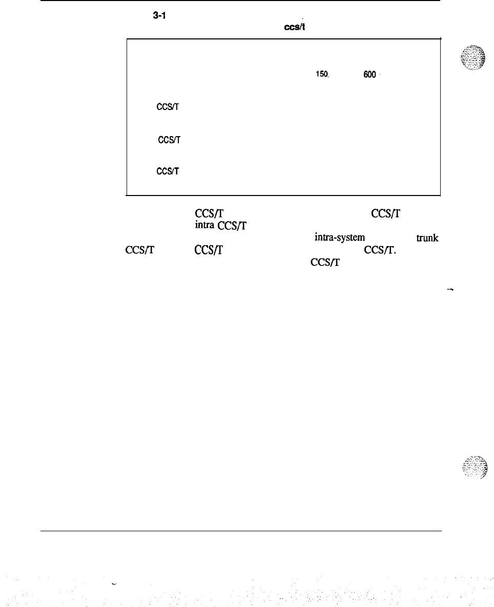
3-6 Provisioning guidelines
Table
3-l
Example of station, trunk, and intra
cc&
averaging
Line size
Line
CCSrr
Trunk
CCST
lntra
CCST
Customer A Customer B
200 250
4.35 4.75
2.6 3.0
1.7 1.75
Customer C
150-
3.5
2.0
1.5
Total Average
600.
200
12.6 4.2
7.6 2.5
4.95 1.65
If only the trunk
CCS/r
is available, then multiply the trunk CCS/T by 0.5
to determine the intra
CCS/r
(assumes a normal traffic pattern of 33%
incoming calls, 33% outgoing calls, and 33% intra-system calls). The trunk
CCS/r
and intra CCS/I’ are then added to arrive at the line CCS/T.
Table 3-2 gives an example when only trunk CCS/lY are known:.
--
System engineering 553-3001-151
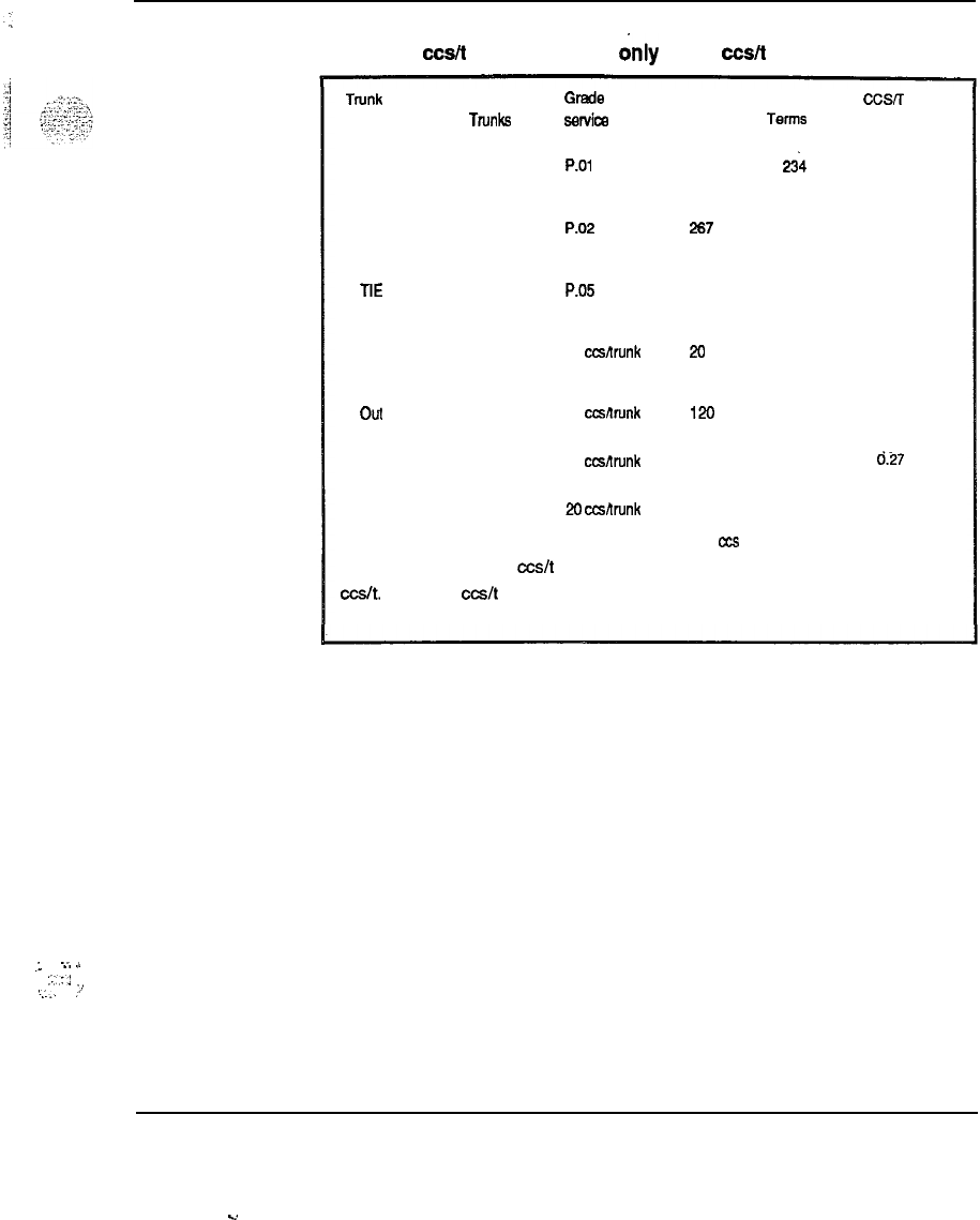
Provisioning guidelines 3-7
Table 3-2
Example of cc&t averaging when drily trunk
c&t
are known
Trunk Type No. of Grede of Load in No. of CCSIT
TN&S
sBrvim CCS T@ltlS
DID 16 P.01 -294
n
1.2
co
14 P.02 267 234 1.14
TIE 07 P.05 116 215 0.54
Paging 02 10 ccsnrunk 20 207 0.09
Out WATS 04 30 ccwlrunk 120 216 0.54
FX 02 30 ccstnrnk 60 216 d.27
Private Line 04 20
CcsRrunk 60 04 20
TOTAL 959 azs 23.79
Mote: The indivuidual
c&t
per trunk group are not added to form the trunk
cc&.
The trunk
c&t
is the total trunk load divided by the total number of lines
at cutover.
.I
. .
-..
.,
:.::
I....
:’
System engineering 553-3001-151
.d
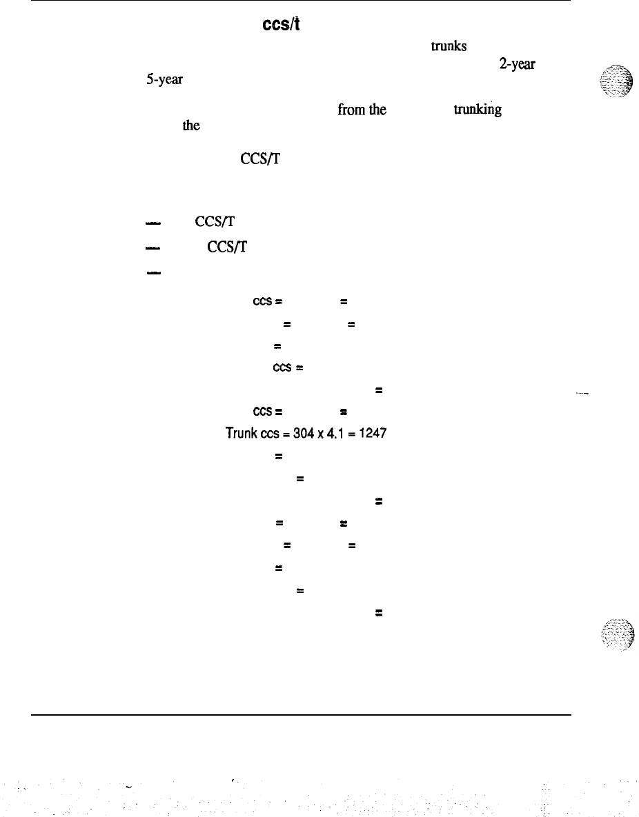
3-8 Provisioning guidelines
Manual calculation of
c&t
Normally, the customer can estimate the number of trunks required at
cutover and specify the grade of service to be maintained at the 2-year and
5-year
period. (If not, the comparative method can be used).
The number of trunks can be read from the appropriate trunk&g table to
select the estimated usage on the trunk group. The number of lines at
cutover that are accessing the group are divided into the estimated usage.
The result is the
CCS/r
which can be used to estimate trunk requirements.
Manual calculation example:
-
Line
CCS/T
= 6.2
-
Trunk CCS/T = 4.1
-
2
Console = 30 CCS
Cutover
2
Years
5 Years
Line
ccs
=
275 x 6.2
=
1705
Trunk ccs
=
275 x 4.1
=
1128
Subtotal
=
2833
Console
ccs
=
30
Total system load
=
2663
Line
ccs
=
304 x 6.2
=
1885
Trunkccs=304x4.1
=1247
Subtotal
=
3132
Console ccs
=
30
Total
system load
=
3162
Line ccs
=
352 x 6.2
=
2183
Trunk ccs
=
352 x 4.1
=
1444
Subtotal
=
3627
Console ccs
=
30
Total system load
=
3657
System engineering 553-3001-151
j
,..._
..-_
.
,.
I
j
..:
-::.
.
.
C>
,,
:‘.
:
I.-
..,
x.
.:
j
Provisioning guidelines 3-9
This method is used for each trunk group
inIhe
system, with the exception
of small special services trunk groups (Tie Trunks, Wats, FX). Normally,
the customer will tolerate a lesser grade of service on these trunk groups.
Table 3-3 has been developed which lists the estimated usage on special
services trunks.
Table 3-3
Estimated load per trunk (ccs)
Tie Trunks
30 ccs
Foreign Exchange
30 ccs
Out WATS 30 ccs
In WATS 30 ccs
Paging
10 ccs
Dial Dictation
10 ccs
Individual Bus Lines
20 ccs
System engineering 553-3001-l 51
3-10 Provisioning guidelines
Default method
Studies have been conducted which estimate the average line
CCS/r
to
never be greater than 5.5 in 90 percent of all businesses. If attempts to
calculate the
CCS/r
using the comparative method or the manual
calculation have not been successful, the default-of 5.5 line
CCS/r
can be
used.
The network line usage is determined by multiplying the number of lines by
5.5
CCS/r.
The total is then multiplied by 2 to incorporate the trunk
CCS/r.
Unfortunately, when this method is used, the intra
CCS/r
is added
twice to the equation, and the result could be over provisioning if the intra
CCS/T is high.
Another difficulty experienced with this method is the inability to forecast
individual trunk groups. The trunk and intra CCS/T is forecasted as a sum
group total. Examples of the Default method and the Manual calculation
method are shown in Table 3-4 for comparison.
Default method example:
-
275
Stations at Cutover
-
304
Stations at 2 years
-
352
Stations at 5 years
Cutover 275 x 5.5 (CCWI’) x 2=3025 CCS Total System Load
2 Year 304 x 5.5
(CCS/r)
x 2 = 3344 CCS
Total System Load
5 Year 352 x 5.5 (CCS/T) x 2 = 3872
CCS Total System Load
--
System engineering 553-3001-151

Provisioning guidelines
3-l
1
-:
.
.
1
~.‘.YY
. .
_
-1
I
.’
Table 3-4
Defautt Method and Manual Calculations analysis
Default Method Manual Calculations
Difference
Cutover
3025
2863CCS
162
CCS
2 Years
3344
3162 CCS
182
CCS
5 Year5
3872
3657 CCS 215 CCS
System engineering 553-3001-l 51
-.
..:
3-12 Provisioning guidelines
Step 3:
Calculate number of trunks required
Trunks required
The values obtained through any of the three previous methods should now
be entered on Worksheet A (provided at the end of this document).
Add
your calculations to the worksheet. Once the trunk CCS/T is known, and a
grade of service has been specified by the customer, the number of trunks
required per trunk group to meet the cutover, 2-year and 5-year
requirements of a customer can be determined as follows:
Example
The customer requires a Poisson 1% blocking grade of service (see Table
3-A at the end of this document). The estimated trunk
CCS/r
is 1.14 for a
DID trunk group. With the cutover, 2-year and 5-year number of lines, the
total trunk CCS is determined by multiplying the number of lines by the’.
trunk
ccs/r:
Cutover 275 (lines) x 1.14 (trunk
CCS/I)
= 313.5 CCS
2year 304 (lines) x1.14 (trunk
CCS/r)
=346.5 CCS
---
5
year 352 (lines) x1.14 (trunk CCS/I’) =401.28 CCS
Use Table 6- 1 to determine the quantity of trunks required to meet the trunk
CCS at cutover, 2-year and 5-year interval. In this case:
-
17 DID trunks are required at cutover
-
18 DID trunks are required at 2 years
-
21 DID trunk are required at 5 yearrs
Note:
For trunk traffic greater than 4427 ccs, allow 29.5 ccs/mmk.
System engineering 553-3001-151
.
.
.:.
I
-.
Provisioning guidelines
3-l
3
Step 4:
Calculate line, trunk, and console load
Line, trunk, and console load
_
Once the quantity of trunks required has been estimated, enter the quantities
on Worksheet A (in Step 1) for the cutover, 2-year and 5-year interval. This
calculation must be performed for each trunk group to be equipped. The
total trunk CCS/T is the sum of each individual trunk group
CCS/r.
This
value is also entered on Worksheet A. (See Worksheet A at the end of this
document.)
Line
load
The line load is calculated by multiplying the total number of 500 and
SL-1 line Terminal Numbers (TN) by the line
CCS/r.
The number of TN is
determined as follows:
. .
-
one TN for every Directory Number (DN) assigned to one or more 500
or 2500~type set
-
one TN for every SL-1 set.
-
one Tn for every digital set M2xxx or M3xxx without data option.
-
two TNs for every M2xxx or M3xxx set with data option.
Trunk load
The trunk load is calculated by multiplying the total number of digital sets,
500, and SL-1 line TN having access to the trunk route by the
CCS/r
per
trunk route.
Console load
The console load is determined by multiplying the number of consoles by
30 CCS per console.
System engineering 553-3001-l 51
3-14
‘hovisioning
guidelines
Step 5:
Calculate DTR requirements
Once station and trunk requirements have been determined for the complete
system, the
Digitone
Receiver (DTR) requirements can be calculated. DTR
are shared by all customers in the system and should be distributed equally
over all the network loops.
Tables 6-3 through 6-6 (at the end of this document) are based on models of
PBX traffic environments and can be applied to determine DTR needs in
most cases. When the system being provisioned does not fall within the
bounds of these models or is equipped with any special features, the detailed
calculations must be performed for each feature and the number of Digitone
receivers must accomodate the highest result.
Some special features are:
-
Centralized Attendant Service (CAS)
-
Direct Inward System Access (DISA)
-
Authorization Code
-
Charge Account for Call Detail Recording (CDR)
-
Integrated Message Service (IMS)
Note:
Refer to the section “Feature calculations” for more information
on the above features.
System engineering 553-3001-151
Provisioning guidelines 3-15
.! ~
.
.
. .
-.
..,
..-
.
.I
.:-
.:
.,
‘:::‘.i:;+
: .
.
,
From the appropriate table (See Table.6-3 to.Table 6-6 at the end of
this
document) determine the number of DTR required and the DTR load for
cutover, two-year, and five-year interval. Record this information on
Worksheet B (located at the end of this document).
The following models are based on some common PBX traffic
measurements:
Model 1
Table 6-3 is based on the following factors:
-
33% intra-office calls, 33% incoming calls, and 33% outgoing calls
-
1.5% dial tone delay grade of service
-
no Digitone DID trunks or incoming Digitone tie trunks
Model 2
.
Table 64 is based on the following factors:
-
assumes same traffic pattern as model 1
-
the system has Digitone DID trunks or incoming
Digitone
tie trunks
-
Poisson 0.1% blockage grade of service
---
Model 3
Table 6-5 is based on the following factors:
-
15% intra-office calls, 28% incoming calls, and 56% outgoing calls
-
1.5% dial tone delay grade of service
-
no Digitone DID trunks or incoming
Digitone
tie trunks
Model 4
Table 6-6 is based on the following factors:
-
assumes same traffic pattern as model 3
-
the system has Digitone DID trunks or incoming
Digitone
tie trunks
-
Poisson 0.1% blockage grade of service
System engineering 553-3001-l 51
3-16 Provisioning guidelines
Detailed calculation: method 1
This method can be used when there are no incoming
Digitone
DID trunks
and the following is assumed:
-
Receiver traffic is assumed to be inflated by 30% to cover unsuccessful
dialing attempts.
-
Call holding times used in Irma-office and Outgoing Call calculations
can be assumed to be 135 seconds if unknown.
-
Receiver holding times assumed to be 6.2 and 14.1 seconds for intra
and outgoing calls respectively.
-
Factor
(l-R)/2
in (1) Outgoing, assumes that Incoming calls and
Outgoing calls are equal. R is the intra-office ratio.
Procedure 3-2
Detailed calculation method 1
1
Calculate Digitone calls:
Intra-office traffic = 100 x Diaitone station traffic (ccs) x
E
call holding time in seconds 2
Outgoing traffic = 100 x Digitone station traffic
X(I-R)
call holding time in seconds 2
2Calculate total receiver traffic:
Total receiver traffic = 1.3 x l(6.2 x Irma) + (14.1 x
out&&]
100
System engineering 553-3001-151
.
.
Provisioning guidelines
3-17
3
Calculate average holding time:.
Average holding time = f6.2 x Intra) + (14.1 x outeoing)
Intra calls + outgoing calls
4Refer to Table 6-7 or Table 6-8 (at
theend
of this document) and use
answers from (2) and (3) above to determine the number of receivers
required.
Detailed calculation: method
2
This method can be used when incoming Digitone trunks are included in the
system. This method uses the same assumptions as method 1, with the
receiver holding time assumed to be 2.5 seconds for a DID call.
Procedure 3-2
Detailed calculation method 1
Calcualte Intra-office and Outgoing Digitone calls as shown in
Method 1 (1):
DID calls = 100 x Dinitone station traffic (in ccs)
call holding time in seconds
Calculate total receiver traffic:
Total receiver traffic =
1.3 x 6.2 x Intra + (1.3 x 14.1 x outeoinp) + (2.5 x DID call@
100
Refer to Table 6-9 (at the end of this document) and use the answer
from (2) above to determine the number of digitone receivers required.
System engineering 553-3001-151
3-18 Provisioning guidelines
Step 6:
Calculate total system load
Total the line, trunk, console, and Digitone receiver load for each customer
to arrive at a total load figure for each customer for the cutover, 2-year, and
5-year interval. Enter this figure on Worksheets B and C (at the end of this
document).
Step 7:
Calculate number of superloops required
The system network loop requirement is the total of all individual customer
loops and superloops required. The number of network loops and
superloops required is calculated for each customer for the cutover, IL-year,
and 5-year interval. Network loops and superloops are provisioned at
cutover on the basis of the 2-year loop requirement figure.
To determine the number of superloops required, first separate the traffic
supported by Enhanced Network Cards (QPC414). Enhanced Networks
support the traffic carried by Data Line Cards (QPC3 11, QPC430,
QPC432), RPE, and DTI/PRI. Remaining traffic including DTR traffic
should be engineered for superloops.
Number of Superloop Network Cards or Number of superloops =
Traffic to be handled bv Superloon Network
2975
These figures are based on an 85% utilization level. The value obtained
should be rounded to the next higher number. For Option 21, exclude the
traffic carried by 10 Intelligent Peripheral Equipment (IPE) Cards in the
first module before computing the number of Superloop Network Cards.
System engineering 553-3001-151
Provisioning guidelines 3-19
Non-blocking configura‘tion with Superloop Network
For non-blocking applications (or non-blocking part of the system),
provide
one superloop per 120 Terminal Numbers (INS). Each line or trunk is one
TN except that an integrated voice and data line is two TNs (assuming dam
port is configured).
Blocking configuration with Superloop Network
For applications where blocking is allowed, one superloop can serve up to
512 lines (1024 TNs). The actual number of lines will depend on the traffic
requirement of the lines.
Enhanced Network Cards (QPC414)
The traffic carried by Enhanced Network Cards includes the data traffic,
RPE traffic, and DTI/PRI traffic (which includes both the data and voice
traffic).
Provide separate loops for RPE and DTI/PRI traffic. Based on 85%
utilization, the number of loops required is calculated as follows:
Number of loops =
Traffic reauired to be carried bv Enhanced Network Cards
560
Number of Enhanced Network Cards = Number of
100~s
2
The value obtained should be rounded to the next higher number.
DTI/PRI
cards
Digital Trunk Interface Cards (DTIs) provide the interface between the SL-1
switch and the
T-l/IX
1 Digital transmission trunks. Digital trunks are
offered in the group of 24 trunks. The number of DTI Cards required can
be found from Table 3-5 when the DTUPRI traffic is known.
Note:
The number of DTI/PRI loops = number of DTI/PRI cards
System engineering 553-3001-151
3-20 Provisioning guidelines
Table 3-5
Number of DTI cards required when DTl/PRI
traffic is known
DTIPRI
traffic
(CCS) Number of DTI cards
1
-
507
1
-
508
-
1201 2
1202
-
1935
3
1936
-
2689 4
2690
-
3456 5
3457
-
4231 6
4232
-
5006 7
5007
-
5781 8
over 5781 provide 8+ one DTI for
each 774 ccs in excess
of 5781
ccs.
Note: In a Network module, if two network slots
are available but not contiguous, the Superloop
Network Card or Enhanced Network Card can be
moved to create a 2” slot for DTI/PRI. The
Superloop Network Card can be plugged into the
left or right half of the “superslot” to achieve this
For non-blocking applications, the Ring Again feature must be provided
since blocking may occur at the far end of the trunk.
Since the DTI/PRI Card physically occupies two network slots, therefore,
the number of DTI/PRI Cards should be multiplied by 2 to obtain the
required number of network slots.
DTI/PRI Cards can be plugged into a Network module, a
Common/Peripheral Equipment module, a Common Equipment module, a
CPU module, or Remote Peripheral Equipment modules. After all essential
cards are configured in these UEMs, estimate the available slots for
DTI/PRI. If enough slots are not available for all DTl/PRIs required, a
special DTI/PRI-only Network module can be added to the system.
System engineering 553-3001-151
Provisioning guidelines 3-21
Step 8:
Calculate number of Network groups required
Compute the number of Network groups based on the total. number of loops
required (excluding conference and tone loops). The following equation
should be used: (Also refer to Table 3-6.)
Total number of loops = 4 x no. of Superloop Network Cards + 2 x
no. of Enhanced Networks
Table 3-6
Number of groups based on the total number
sf
loops required
Number of groups Number of loops
Note: Use Worksheet C (at the end of this
document) if no superloop is required. If the total
number of loops required exceeds 22, then a
multiple group system should be installed.
1
28
2 56
3
84
4 112
5 140
Based on the above criteria, installing a multiple group system at the start is
more cost-effective than converting to a multiple group system (from a
single gropu system) between the 2-year and 5-year interval.
:.
-.
I
:.:::,
i
;
.
.
.
.
::_
:‘-
-.-”
.-.~.-
-:
--?sq
.,
System engineering 553-3001-l 51
3-22 Provisioning guidelines
Step
9:
Calculate number of PE cards required
Enter the number of Digitone receivers required (from Worksheet B) at the
cutover, 2-year, and 5-year interval on Worksheet D. Use a separate
worksheet for the cutover, 2-year, and 5-year intervals.
Using the information on Worksheet A, enter the number of M2xxx TNs,
M3xxx TNs, NE-500/2500 TN, SL-1 TN, and trunk TN required at the
cutover, 2-year, and 5-year interval (for all customers).
Divide each entry by the number of terminal number assignments per card,
round up to the next highest figure, and total the number of cards required.
Calculate the number of new cards and old cards separately.
Note:
Worksheets are provided at the end of this document.
Step
10:
Calculate number of PE
UEMs
required
The number of PE UEMs provided at cutover is based on the 2-year
estimate of PE cards required and an 85% utilization level. The maximum
capacity of an Intelligent Peripheral Equipment (IPE) Module is 256
Integrated Voice and Data (IVD) or analog lines; however, a typical
configuration should include a combination of line, trunk, and
digitone
receivers which provides up to 160 lines with appropriate trunks.
Divide the number of PE cards required at 2-years by 8.5, round to the next
higher figure, and enter this value on Worksheet D (at the end of this
document).
To compute the number of Peripheral Equipment (PE) UEMs, total the
number of line cards, trunk cards, and Digitone receiver cards required at 2
years by 13.6 and round to the next higher integer figure. Enter this value
into Worksheet D (located at the end of this document).
Calculate the number of IPE UBMs and PE UEMs required.
System engineering
553-3001-151
‘...
:
.
.
Provisioning guidelines 3-23
Step 11:
Provision
YEWConference
loops
Tone and Digit Switch (TDS) and Conference (CONF) loops are
provisioned according to the two-year figure for the number of network
loops required. All systems should be equipped with a minimum of two
TDS and two CONF loops.
Refer to Table 6- 10 (at the end of this document) to determine TDS and
CONF loop requirements for systems other than SL-1 S. Enter these figures
on Worksheet F (at the end of this document).
uirements
Refer to the end of this document and use Worksheets G through
fto
calculate memory needs. The two-year figure for sets, consoles, trunks, for
example, should be used when calculating. Once the total memory needs
are determined, add an additional 10% to the total.
---
Step 13:
Assign
the equipment
/
prepare equipment
summary
Equipment summary
Use Worksheet J (at the end of this document) to record the equipment
requirements for the complete system at cutover. Proceed to assign tire
equipment. The equipment summary may have to be updated as a result of
assigning procedures. The equipment summary, once finalized, may be
used to order the equipment for the system.
System engineering 553-3001-l 51

_:-
4-1
Feature calculations
Calculations with Authorization Code
With authorization code, the receiver holding times are changed from 6.2
seconds to 19.6 seconds for intra-office calls, and from 14.1 seconds to 27.5
seconds for outgoing calls.
Use these figures in (2) and (3) of Detailed calculation Method 1,‘and (2) of
Detailed calculation Method 2 when calculating the DTR requirements for a
system with the authorization code option.
The following is assumed.
-
All Digitone intra-office and outgoing calls require authorization.
.-_
-
The average number of Special Services Prefix (SSP) digits is 2 (the
maximum is 4).
-
The average number of authorization code digits is 10 (range is 1 to 14
digits).
-
The average receiver holding time is 13.4 seconds.
Note: See Table 6-7 at the end of this document.
System engineering 553-3001-l 51

4-2 Feature calculations
Calculations with Centralized Attendaht Service (CAS)
This method is used to determine the DTR requirements for the main
location of a system equipped with the CAS option. The following is
assumed:
-
All attendant calls presented through Release~Link Trunks’ (RLT) from
a remote PBX require
Digitone
Receivers.
-
The average number of digits dialed is 4.
-
Average receiver holding time is 6.2 seconds.
Procedure
4-l
Calculations with CAS
1
Calculate the attendant calls from the remote PBX:
attendant call = 100 x attendant traffic from the remote (CCS)
attendant work time (in seconds)
2Add the attendant calls to the intra-office calls calculated in (1) of
Method 1, and proceed with the remaining calculations of Method
1.
,--t--Y
_
._
A.,.
::
:
-
r:,
-.
3
:;
.a
System engineering 553-3001-151
Feature calculations
4-3
Calculations with Charge Account for CDR
The receiver holding time for outgoing calls changes from 14.1 seconds to
20.8 seconds.
Apply this change to (2) and (3) in Method 1 and (3) in Method 2 to
determine DTR requirements for a system with the charge account for CDR
option.
The following is assumed:
-
50% of the Digitone outgoing calls require charge account.
-
The average number of SSP digits is 2 (maximum is 4).
-
The average number of digits in the account number is 10 (range is 2
to
23 digits).
-
The average receiver holding time is 13.4 seconds. See Table e-7.
System engineering 553-3001-l 51
C.
4-4 Feature calculations
Calculations with Direct inward System Access (DISA)
This method is used when a system is equipped with DISA. The following
is assumed:
-
The DISA calls come through DISA trunks or DID trunks.’
-
75% of DISA calls require security code.
-
The average number of digits in the security code is 4 (range is 1
tc
8).
-
The DISA receiver holding time is 6.2 seconds.
Procedure 4-2
Calculations with DISA
1
Calculate the number of DISA calls.
DISA calls = 100 x DISA traffic
call holding time
2Calculate the DISA receiver traffic.
DISA receiver traffic = 6.2 x DISA calls
100
3Add this traffic to (2) in Method 2 and proceed with the remainder
.__
of Method 2 calculations.
System engineering 553-3001-151
.
.
Feature calculations 4-5
Calculations with Integrated Message Service (IMS)
This method is used when a system is equipped with IMS. The following is
assumed:
-
Only messaging calls from 2500 sets require
DigitoneReceiver
service
-
50-50 split of originating and terminating calls and 135 seconds
average call holding time were assumed in Step (a).
-
50% of calls from 2500 sets were intra-PBX calls Step
(b).
-
In general, a caller will not wait until the completion of Recorded
AMOMCement
to act (press message button or transfer to attendant).
The average time is listening to an announcement is four seconds, (Step
d).
-
If the actual number of 2500 sets is not known, assume it to be 60% of
total lines.
Procedure 4-3
Calculations with IMS
1
Calculate originating calls from 2500 sets of the PBX.
Calls from 2500 sets = CCS/line x 100 x Qty 2500 sets/(2x135) = A_-
2Calculate intra-PBX calls from 2500 sets.
Irma-PBX 2500~set calls = A x 0.5 = B
3Calculate calls requiring service of DTR.
Calls to DTR = B x 0.5 = C where 0.5 is the fraction of B which goes to
the messaging service.
4Calculate traffic (CCS) to DTR.
Messaging CCS to DTR = C x 4/100
Messaging CCS should be added to the total DTR traffic to determine
the overall DTR requirements.
System engineering 553-3001-l 51
‘.d

5-1
Worksheets
Worksheets 5-l
Growth Forecast: Worksheet A5-2
Line Usage: Worksheet B5-4
Network Loop Calculation : Worksheet C5-6
PE Card Calculations : Worksheet D5-8
Universal Equipment Module Provisioning : Worksheet E
‘-
5-10
Conference Loop Requirements : Worksheet F
5-11
Unprotected Memory Calculations : Worksheet G5-13
Protected Memory Calculations : Worksheet H5-16
Program Store Calculations : Worksheet I5-19
Equipment Summary : Worksheet J
5-21
Balancing Network Loops : Worksheet K
5--23
Load Balancing : Worksheet L5-24
Card Distribution : Worksheet M5-26
Multiple Appearance Groups Assignments : Worksheet N5-27
Station Load Balancing : Worksheet 05-28
Card Assignment : Worksheet P5-30
TN Assignment Record : Worksheet
Q
5-32
System Assignment Plan : Worksheet
R
5-35
Multiple Appearance Group Record : Worksheet S5-36
System engineering
553-3001-l 51
.
.
.I..
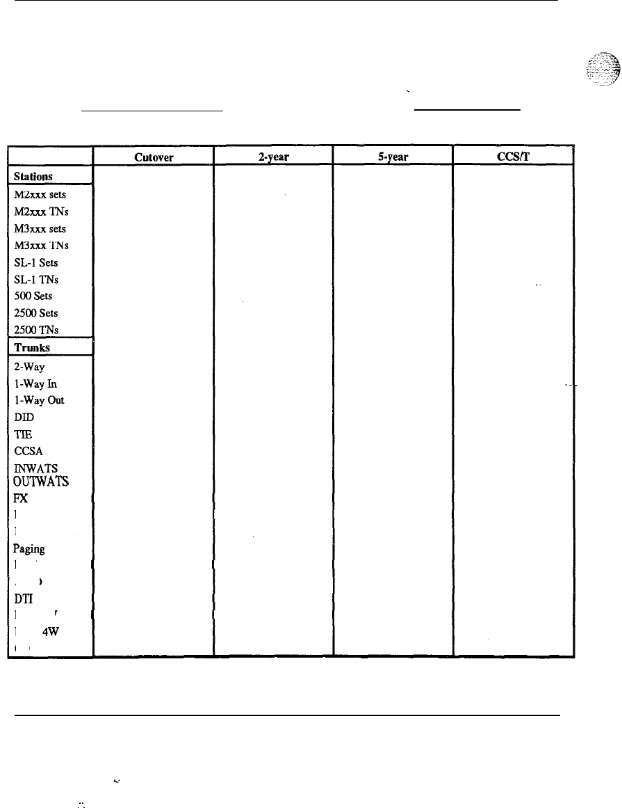
5-2 Worksheets
Worksheet A
Growth forecast
One sheet for each customer, one sheet for the system
as a whole.
Customer:
Date:
-
OUTWATS
Fx
Private Line
Dial Dictation
Paging
RAN
AIOD
DTI
E&M 2W
E&M
4W
co
System engineering 553-3001-151
.d
.-
-.
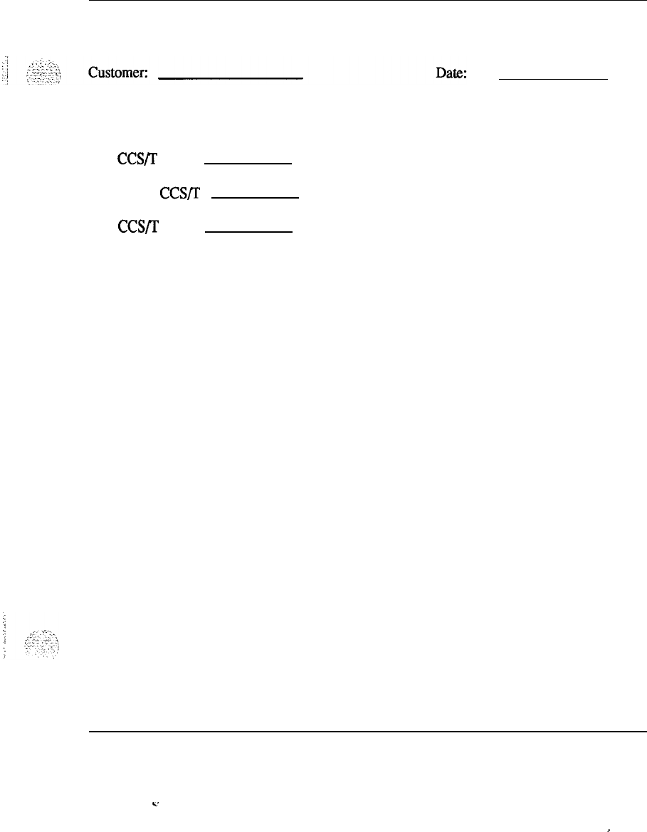
Worksheets 5-3
Worksheet A continued
Growth forecast
Line
CCS/r
Total Trunk CCS/T
Intra CCSjT
System engineering 553-3001-l 51
c.
I
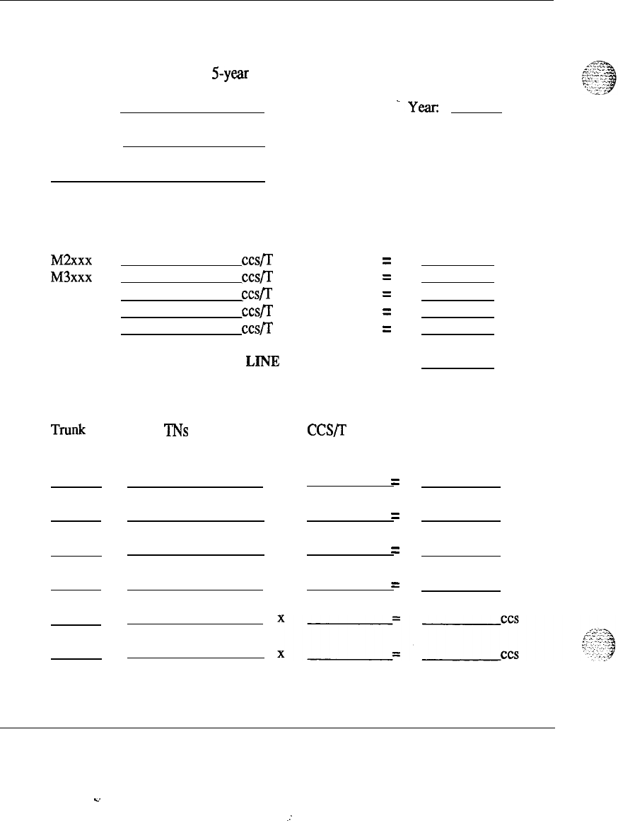
5-4 Worksheets
Worksheet B
One sheet for each customer for cutover, 2-year, and 5-year intervals. One for the
system cutover, 2-year, and 5-year intervals.
Customer:
-year
Address:
Line usage
M2xxx
TN
X
ccsfr =
ccs
M3xxx
TN
X
ccs/T =
ccs
SL-1 TN
X
cc&s/r
=
ccs
500 TN
X
ccs/T =ccs
2500 TN
X
ccs/T =ccs
TOTAL LINE LOAD =ccs
Trunk usage
---
TlWlk
Route No of TNs
Accessing Route
CCS/r
Per
Trunk Route Total CCS Load
Per Trunk Route
X
=
ccs
X
=
ccs
X
=
ccs
X
=
ccs
System engineering 553-3001-151
c.
.:
,:
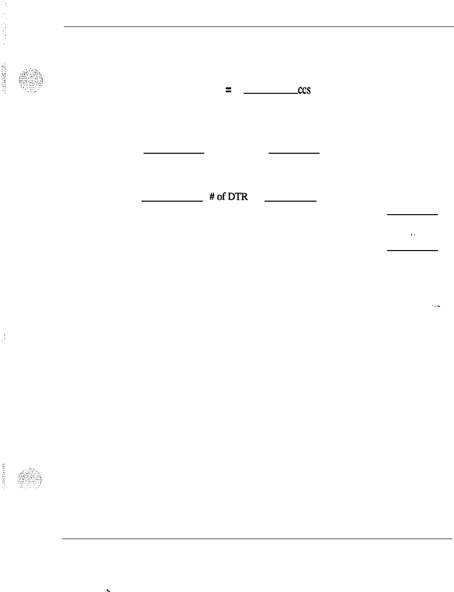
Worksheets 5-5
Worksheet B continued
TOTAL TRUNK LOAD
=
CCS
Console usage
No.
of
Consoles
x 3occcs =
Total Console Load
Digital Receivers
Table
#ofDTR
Total DTR Load
ccs
Total Load
‘-
ccs
System engineering 553-3001-l 51
.
.
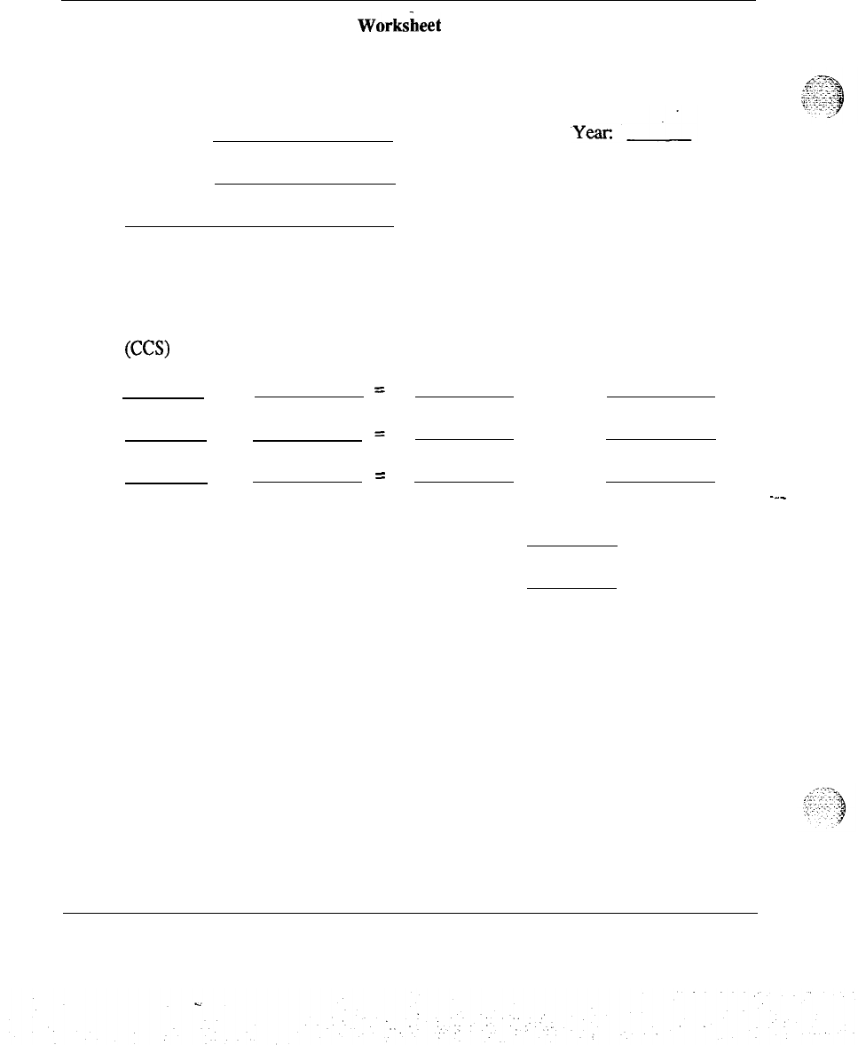
5-6 Worksheets
Work!&?et
c
One sheet for each customer.
One sheet for the complete system.
Customer:
Address:
Network loop calculation
Total load
(CC9
ccs /Loop
Cutover
2-year
5-year =
No. of loops Round to next
highest figure
---
Number of Network Loops Required at 2 Years =
Number of Network Groups Required at 2 Years =
(Use Table C- 1 Below)
System engineering 553-3001-151
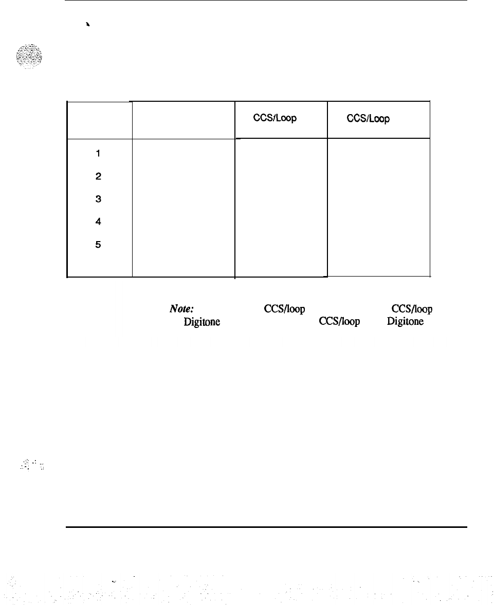
Worksheets 5-7
Worksheet C continued
..:-
.:
.I-.
‘..:
.
.
Table C-l
Network groups required at 2 years
No.
of
Network
Groups
Maximum No.
of Voice Loops
24
48
72
96
120
No DGT Trunks
in CCSlLoop
560 500
13440 12000
26880 24000
40320 36000
53760 48000
67200 60000
Wiih DGT Trunks
in CCSlLoop
540 485
12960
11640
25920 23280
38880 34920
51840 46560
64800 58200
Note:
The maximum CCS/loop for any SL-1 is 600 CCS/loop when
no Digitone Trunks are used or 580 CCS/loop when
Digitone
Trunks
are used.
System engineering 553-3001-l 51
5-8 Worksheets
Worksheet D
One for the complete system at cutover, 2-year, and 5-year intervals.
Customer:
Year:
Address:
Table D-l
PE card calculations
No. of
ISDgl
LC
CUT
=
No. of
DTR =
No. of 500 TN
4=
No. of SL-1 TN
4=
No. of Consoles
No. of
CO/FX/ Wats/Private Link Trunks =
2
No. of 2-Wire
E&M/DX/Pahuz
Trunks =
2
2-YR
5YR
System engineering 553-3001-151
I
.
.
Worksheets 5-9
Worksheet D continued
:.:
.
_,-...
:.
-cd
_
.
./
Table D-l continued
e
,.e
(I
.
-.....
;.-‘j
-.-=.’
,*:
‘i
PE card calculations
CUT
2-YR
5YR
.
No. of
LOOD
Sienaline/DID
Trunks
I
I-
I
2
No. of Dictation Trunks
2
No. of Recorded Announcement Trunks
4
No. of AIOD Trunks
.
No. of 4-Wire E&M/DX Trunks
2
TOTAL CARDS
Use the total cards required at 2 years to determine the number of PE
UEMs
to be provisioned at
cutover.
PE
UEMs
required =
8.5
(Round to next highest number)
Number of PE
UEMs
required at cutover
PE UEM calculations
. .
‘.‘>.
,:_
,,_
_:,
System engineering 553-3007 -7 57
5-10 Worksheets
Table D-l continued
PE card calculations
No. of Dgtl LC =
CUT 2-YR
Number of digital ports in service + number of
TCM consoles x 6
No. of Anlg LCs =
Number of analosr ports in service
16
No. of
Anlg
M/W LCs =
Number of analog norts with Message Waiting
feature in service
16
No. of XUT =
Total number of CO/DID/RAN/PAGE trunks
8
5-YR
No. of XEMs =
Total number of E&M/PAGE/Dictation trunks
4
TOTAL CARDS
Notes: Do not configure more than one TCM console on one Dgtl LC
for higher reliability. Try to spread Dgtl LCs supporting consoles over
different XPE UEMs and different superloops for even higher
reliability. Use paging trunks on XUT or XEM depending on what
combination minimizes the total number of trunk cards required.
System engineering
553-3001-151
.
.
Worksheets
5-l
1
WorksheetE
One sheet for the complete system.
Customer:
Address:
Date:
UEM provisioning
(1) Single network group system CPU UEM
PE UEM
(2) Multiple network group system CPU UEM
Network UEM
PE UEM
1
---
System engineering
553-3001-l 51
C.
:
:
.
.
..:

5-l
2 Worksheets
Worksheet F
One sheet for the complete system.
Customer:
Date:
Address:
Conference loop requirements
Conference loops are provisioned according to the 2-year network loop requirements.
Conference Loop Required =
Tone and Digit loop requirements
Tone and Digit loops are provisioned according to the 2-year network loop
requirements.
Tone and Digit Loops Required =
Estimated real time usage calculation
.
ERTU=
BLlneT
/2100
150
= Percent Utilization of CPU Real Time
System engineering 553-3001-151
.
..
.
,
_..
:..
:
-.

Worksheets 513
Where:
Worksheet F continued
Total Line Load is the 2-year figure
T= the average processing time for a call in seconds;
use 0.6 for a single network group system, or
0.24 for a multiple network group system
150 = the average holding time
2100 = the maximum useable real time of the CPU in seconds
System engineering 553-3001-l 51
. .
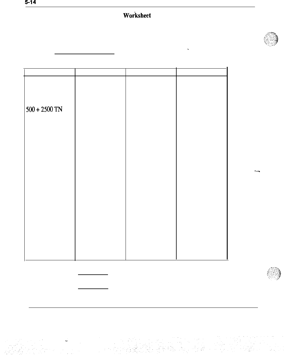
5-14
Worksheets
Woiksheet
G
One sheet for the complete system.
Customer:
Date:
-
Fixed Amount of
Storage Required
500+2500TN
SL-1 TN
Add-On Modules
Network Groups
Trunk Circuits
Consoles
Customer Groups
Trunk Routes
Network Loops
(Excluding
Conference)
RPE Loops
Items Words Total
---
Total
Total words
(Include total from second worksheet)
(Include total words from second worksheet)
System engineering 553-3001-151
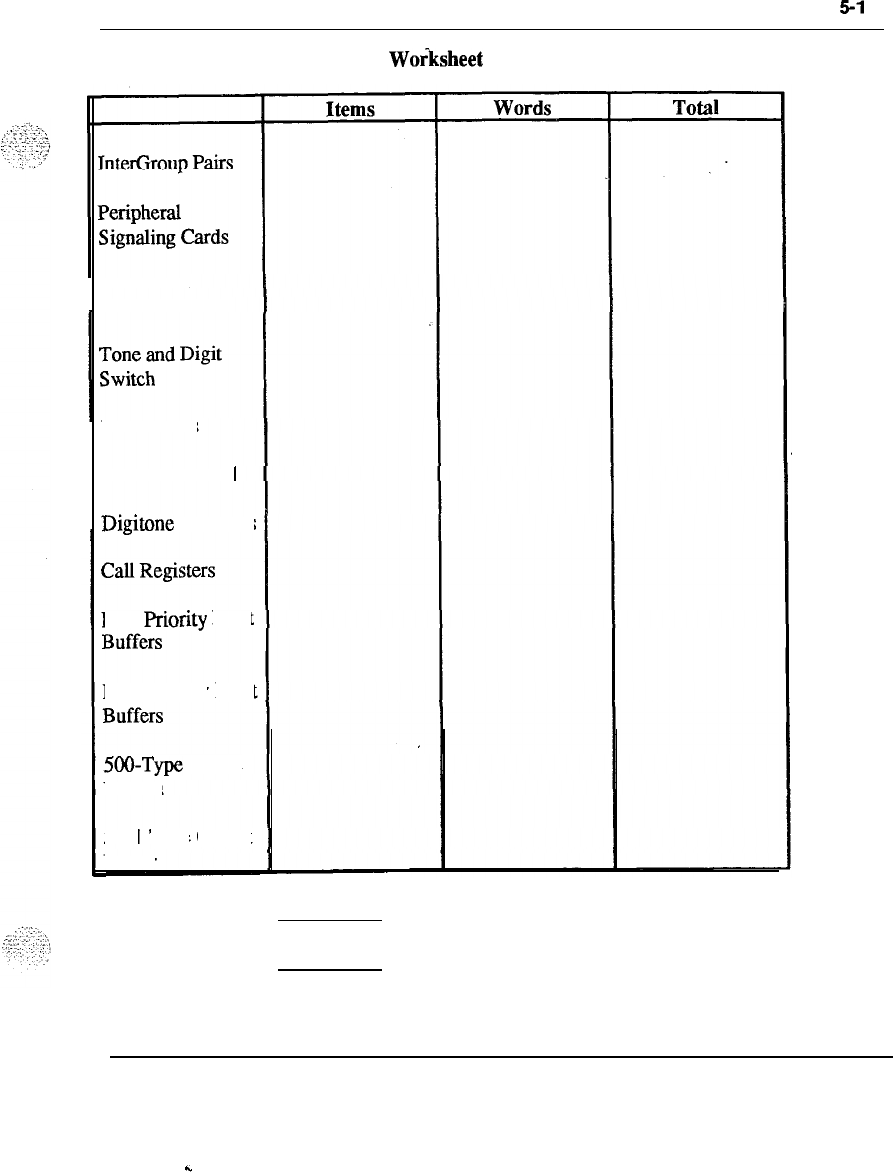
Worksheets
5-l
5
Woiksheet
G continued
Serial Data
Interface Cards
MF Senders
Conference Card
Digitone
Receivers
Low
priority
Input
High priority
Input
NO-Type Output
Buffers
SL- 1
Type
Output
Buffer
Total (Add to first page total)
Total words (Add to first page total words)
System engineering 553-3001-151
c

5-16 Worksheets
Worksheet
‘C
continued
Memory Card Code
Capacity
Unprotected Memory Cards Required
Memory Card Addresses Required
OPC/NT
-
k words
(lk
= 1024 Words)
System engineering 553-3001-151
.
.
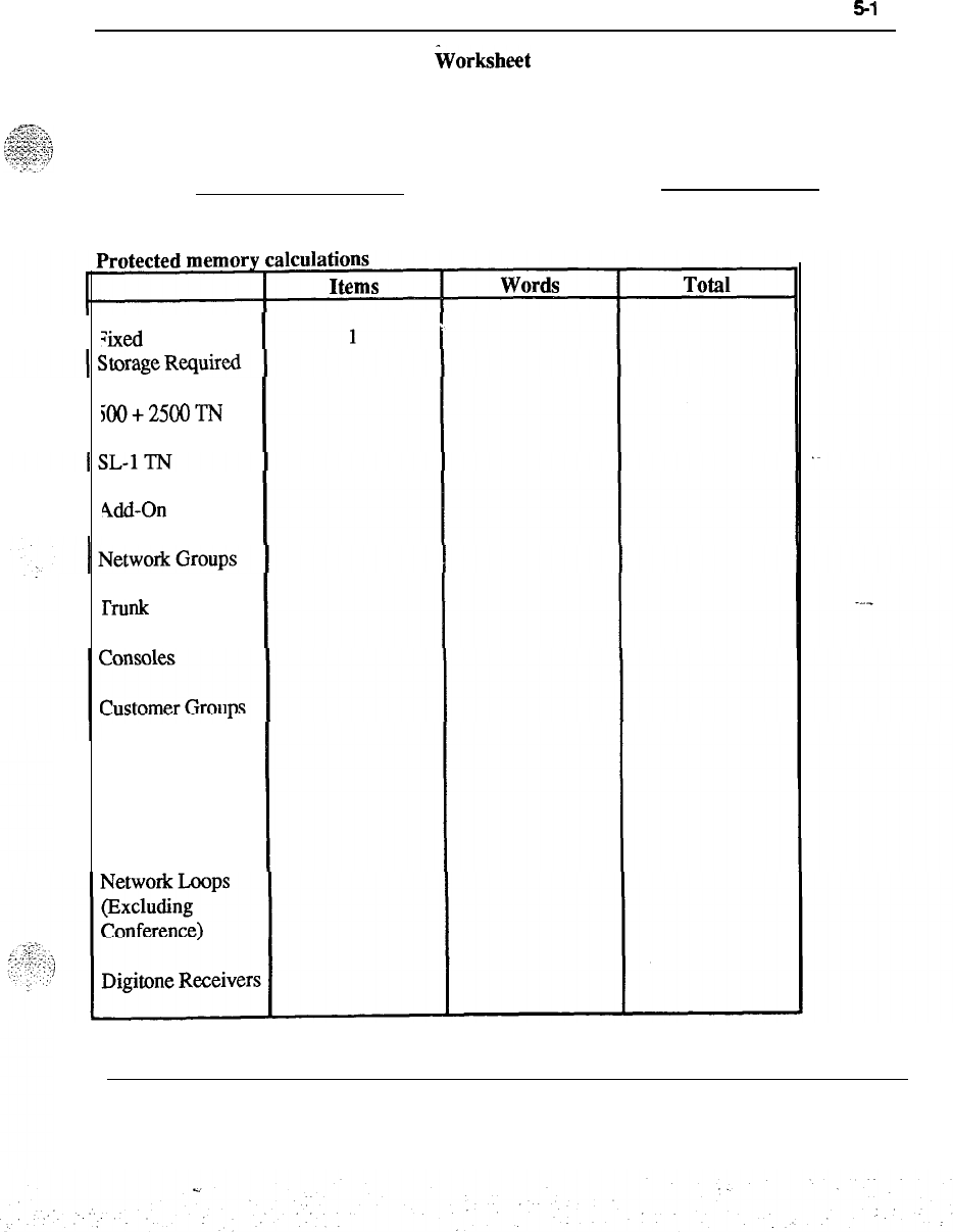
Worksheets
5-l
7
iVorksheet
H
One sheet for the complete system.
Customer:
Table H-l
Date:
Gxed Amount of
500+25OOTN
kid-On
Modules
lhnk
Circuits
Trunk Routes
Code Restricted
Trunk Routes
System engineering 553-3001-l 51

5-18 Worksheets
Worksheet H continued
Total
Add 10%
Total words
(Include total from third page)
(Include total words from third page)
Memory Card Code
Capacity
Protected Memory Cards Required
Memory Card Addresses Required
OPC/NT
k words (lk = 1024 Words)
System engineering 553-3001-151
.
.
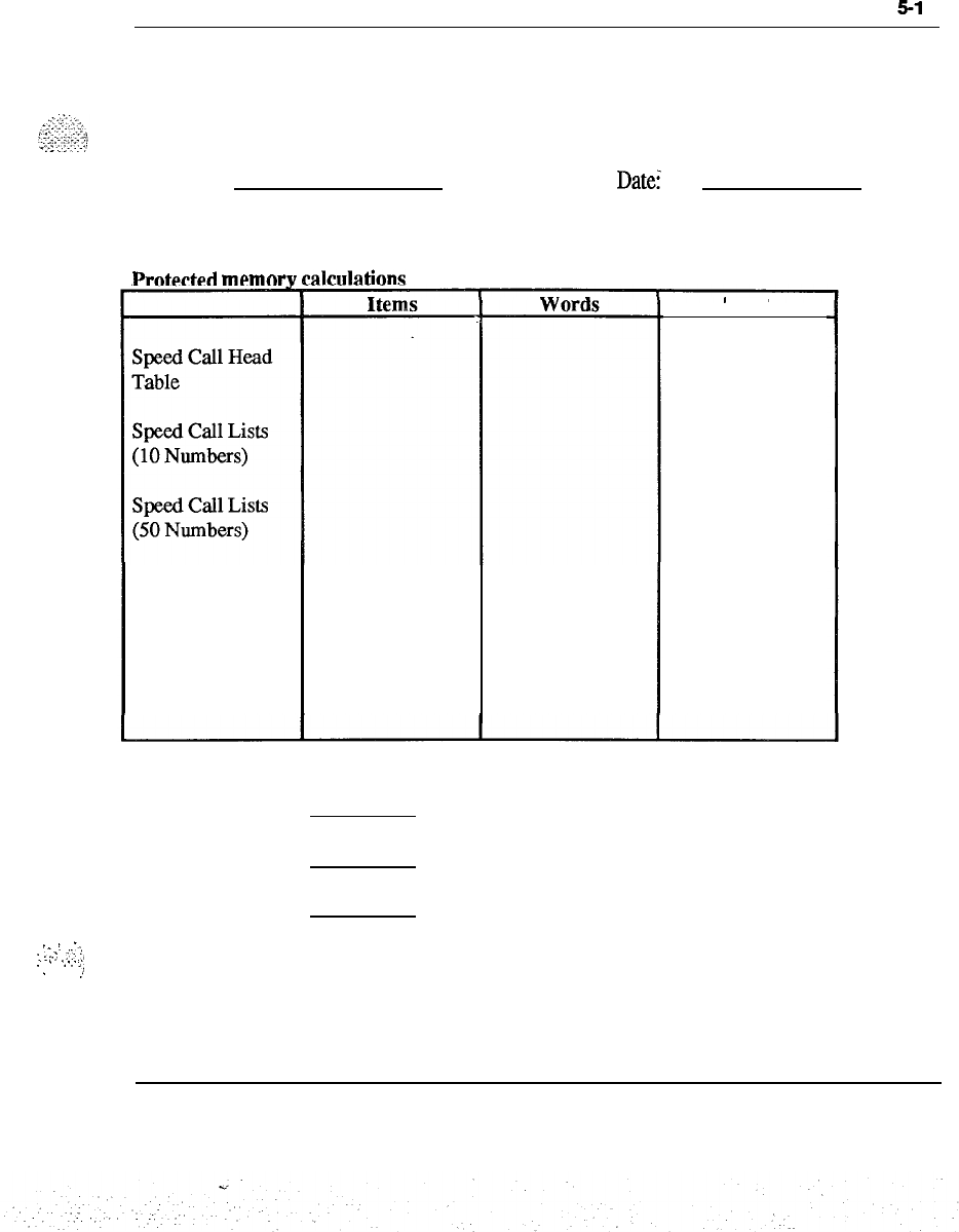
Worksheets
5-l
9
Worksheet H continued
One sheet for the complete system.
Customer:
Table H-l continued
Prntertedmemnrv
calcdatinnn
Datei
Tone and Digit
Switch
Conference Card
History File
Total
Total
Add 10%
Total words
(Add to first page total)
(Add to first page total words)
.
/
._
:..
:
.
.
..I
..I..
:,
;
.
._
.
.
.
.
.
.,
.
.
,,
System engineering 553-3001-151
5-20 Worksheets
Worksheet I
One sheet for the complete system.
Customer: Date:
Program store calculations
Program Name
Basic
Overlay Area
Read Only Memory
Storage in k
(lk = 1024 words)
Total =
Total x 1024 =
k
words
System engineering 553-3001-151

Worksheets
521
Worksheet I continued
Memory Card Code
Capacity
Program Store Cards Required
Memory Card Addresses Required
QPCNr
k words (1 k = 1024 Words)
;_-.:
.
:
‘._..
:.’
:
“.’
System engineering 553-3001-151
.
.
:..-
:
.
.
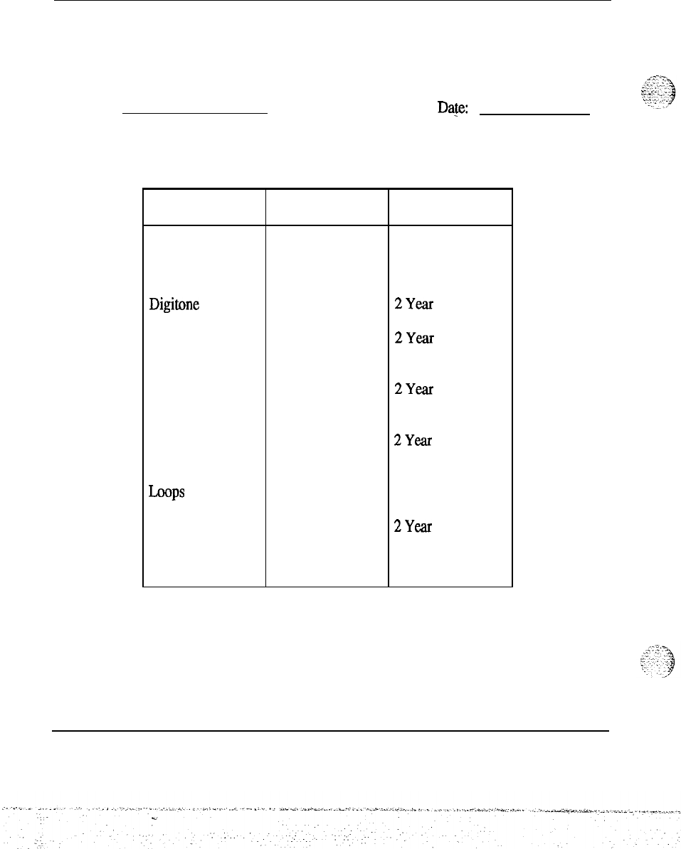
5-22 Worksheets
Worksheet J
Equipment summary
One sheet for the complete system.
Customer:
Da&e:
Table J-l
Equipment summary
Equipment
summary Quantity Based on figure
Line and Trunk
Cards Cutover
Digitone Receivers
Unprotected
Memory Cards
2Year
2Year
Protected Memory
Cards
2Year
Conference Loops
Tone and Digit
-Ps
2Year
2Year
Call Registers
High Priority Input
Buffers
2Year
Cutover
System engineering 553-3001-151
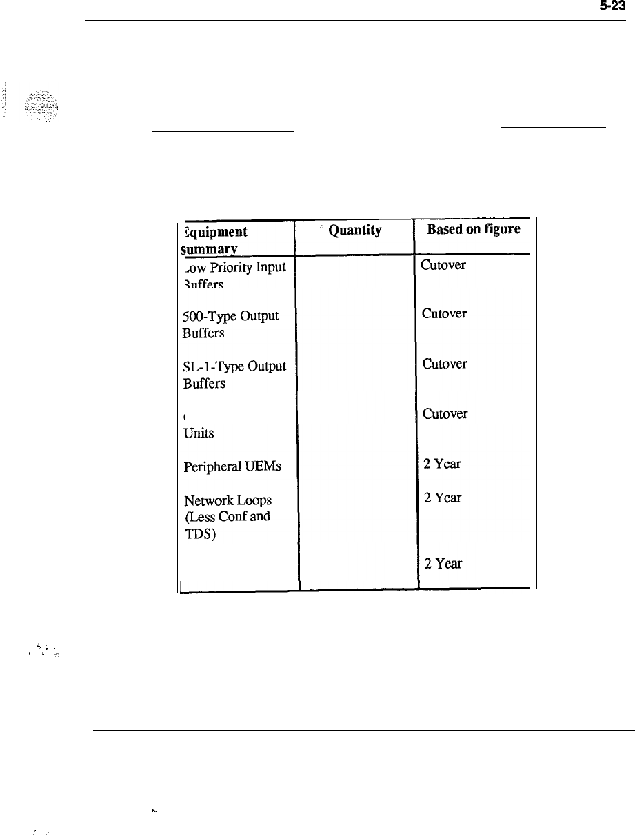
Worksheets
$23
Worksheet J continued
One sheet for the complete system.
Customer:
Table J-1 continued
Equipment summarv
I
5
II
Central Processing
Date:
Network Groups
. .
.
.
.
.
.
,:
System engineering 553-3001-151
.
.
:
:
5-24 Worksheets
WorksheetK
One sheet for the complete system.
Customer:
Table K-l
Balancing network loops over network groups
Date:
-
Customer
Network Network
Group 0
Group 1Network
Group 2Network
Group 3
Network
Group 4
System engineering 553-3001-151
C.
:
::
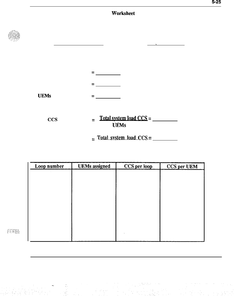
Worksheets
525
Work!dleet L
One sheet for the complete system.
Customer:
Date:
_
-
;:.-
‘,“-.::.:
:
:‘;
:.
.:,::.;
Load balancing
Total system load
Voice loops required
PE
UEMs
required
ccs
Average CCS per UEM
=Tatalsystemload=
ccs
PE
UEMs
required
Average CCS per Loop
Table L-l
Load
balancing
=
Tota1
svstem
load
CCS =
ccs
Voice loops required
System engineering 553-3001-151
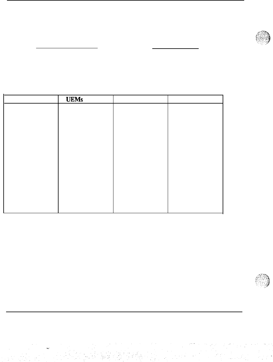
5-26 Worksheets
Worksheet L continued
One sheet for the complete system.
Customer:
Table L-l
Load balancing
Date:
Loop number
UEMs
assigned CCS
per loop
CCS per UEM
System engineering 553-3001-151
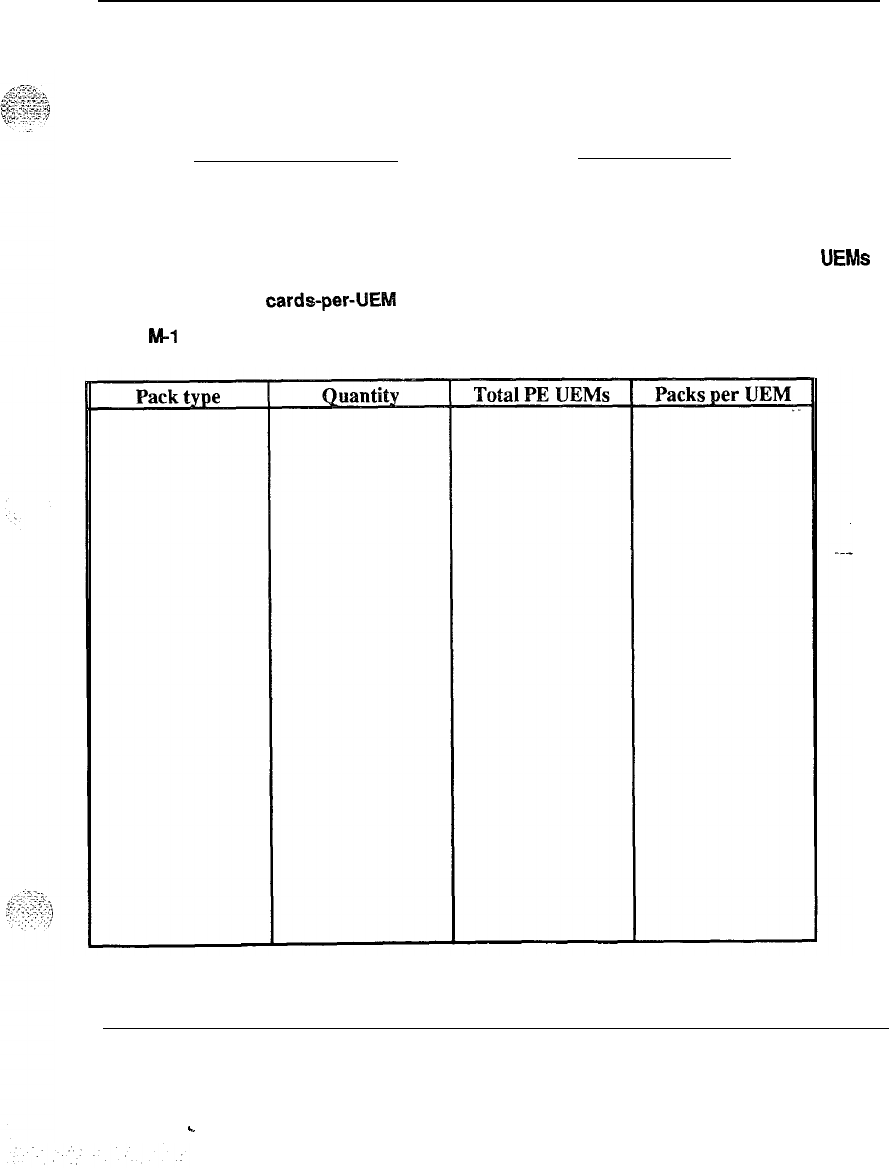
Worksheets 527
Worksheet M
Customer: Date:
One sheet for the complete system.
Card distribution
Divide the total number of a card type by the total number of BE UEMs
to arrive at a
cards-peNEM
figure:
Table M-l
Card distribution
System engineering 553-3001-151
.
.
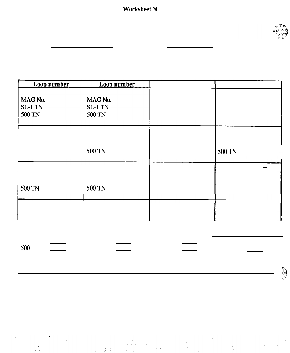
5-28 Worksheets
WorksheetN
One sheet for the complete system.
Customer: Date:
Table N-l
Multiple Appearance Group (MAG) assignments
MAG No. MAG No.
SL-1 TN SL-1 TN
5ooTN
5ool-N
MAG No. MAG No.
SL-1 TN SL-1 TN
500-I-N
5ooTN
MAG No. MAG No.
SL-1 TN SL-1 TN
5ooTN 5ooTN
SL-1 Packs
500
Packs SL-1 Packs
500 Packs
Loop number
MAG No.
SL-1 TN
5ooTN
MAG No.
SL-1 TN
5ooTN
MAG No.
SL-1 TN
5ooTN
MAG No.
SL-1 TN
5ooTN
SL-1 Packs
500 Packs
Loop number
MAG No.
SL-1 TN
5ooTN
MAG No.
SL-1 TN
500-I-N
---
MAG No.
SL-1 TN
5ooTN
MAG No.
SL-I TN
5ooTN
SL-1 Packs
500 Packs
System engineering 553-3001-151
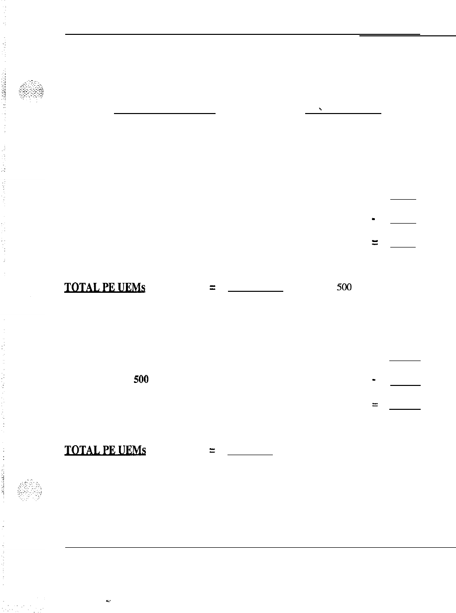
Worksheets 5-29
-Worksheet 0
One sheet for the complete system.
Customer:
Date:
-
Station load balancing
Total SL-1 TN to be assigned
Less number of SL-1 TN assigned to MAG
m
Equals number of SL-1 TN not in MAG =
TOTAL
SL-1 TN not in MAG
Number of 500 TN not in
MAG assigned per UEM
TOTAL 500 TN to be assigned
Less number of 500 TN assigned to MAG
Equals number of 500 TN not in MAG
500 TN not in MAG
Number of 500 TN not in
MAG assigned per UEM
System engineering 553-3001-151
s.
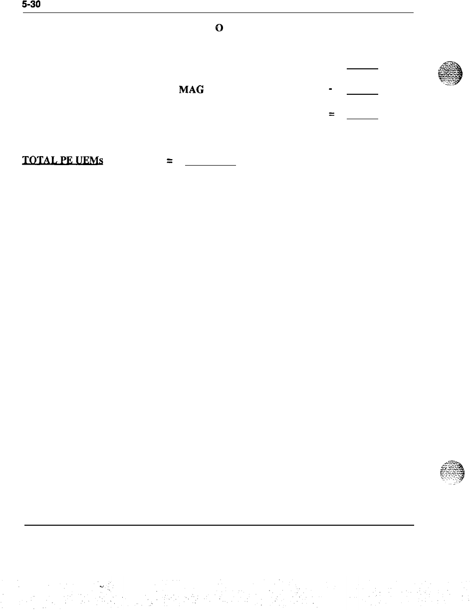
5-30
Worksheets
Worksheet
0
continued
Total 2500 TN to be assigned
Less number of 2500 TN assigned to
MAC
Equals number of 2500 TN not in MAG
2500
TN not in MAG
Number of 2500 TN not in
MAG assigned per UEM
System engineering 553-3001-151
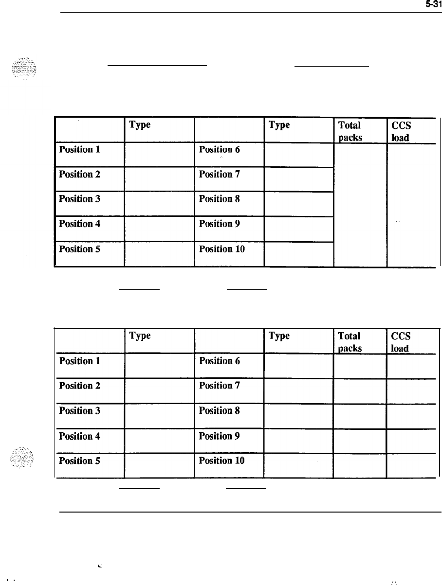
Worksheets
531
-Worksheet P
Customer: Date:
Table P-l
Card to UEM assignment
Loop number UEM number
Table P-2
Card to UEM assignment
Loop number UEM number
System engineering 553-3001-151
C.
..
.-
-.

5-32 Worksheets
Customer:
Table P-3
Card to OEM assignment
Worksheet
.P
continued
Date:
Loop
number UEM number
Table P-4
Card to UEM assignment
Total
packs
ccs
load
Loop
number UEM number
System engineering 553-3001-151
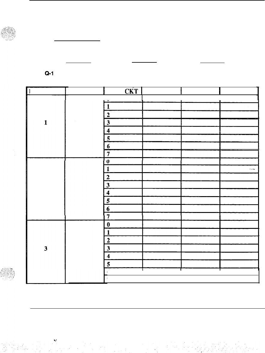
Worksheets 5-33
-Worksheet Q
One
sheet for each PE UEM in the system.
Date: DN = Directory Number
RTMB = Route Member Number
Loop number UEM number Group number
Table
Q-l
TN assignment record
Pack
pos
2
Pack type
1
Pack
CeT
1 DN
1
RTMB
1
CUST
In
II
I
6
III
7
System engineering 553-3001-151
Y
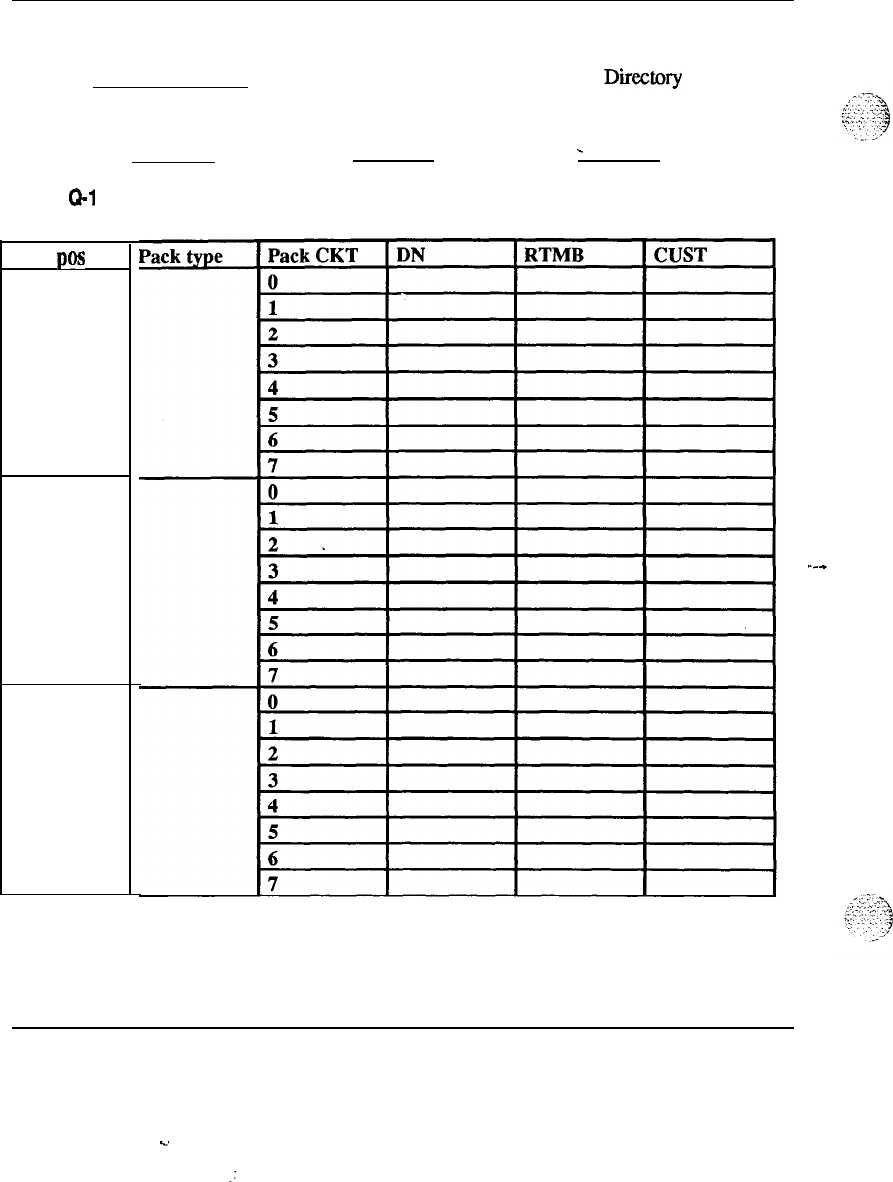
5-34 Worksheets
Worksheet Q continued
Date: DN = Directory Number
RTMB = Route Member Number
Loop number UEM number Group number
-
Table
Q-1
continued
TN assignment record
Pack
pas
4
5
6
System engineering 553-3001-151
C.
.:
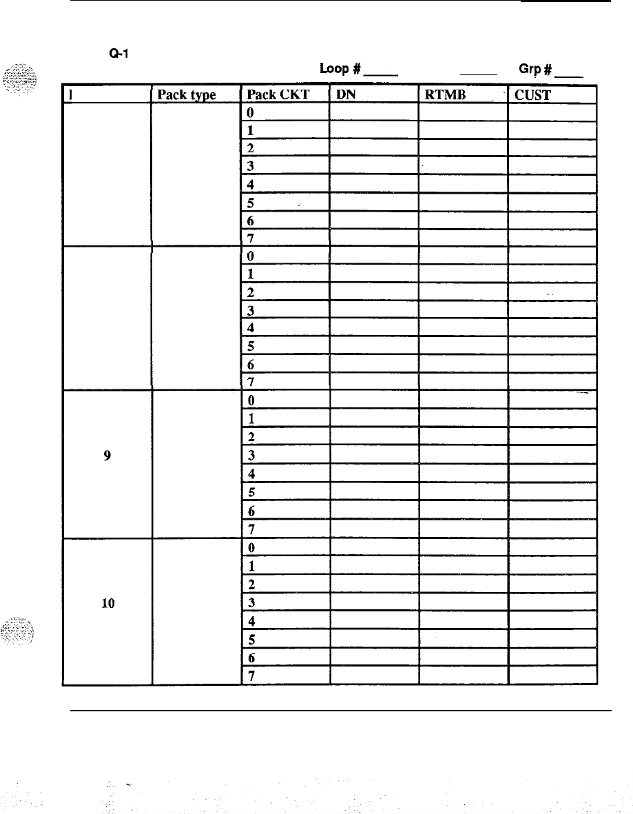
Worksheets 535
Worksheet Q continued
Table Q-l continued
TN assignment record
hop
#-
UEM #
Grp
L.-
Pack
pos
7
8
System engineering 553-3001-151
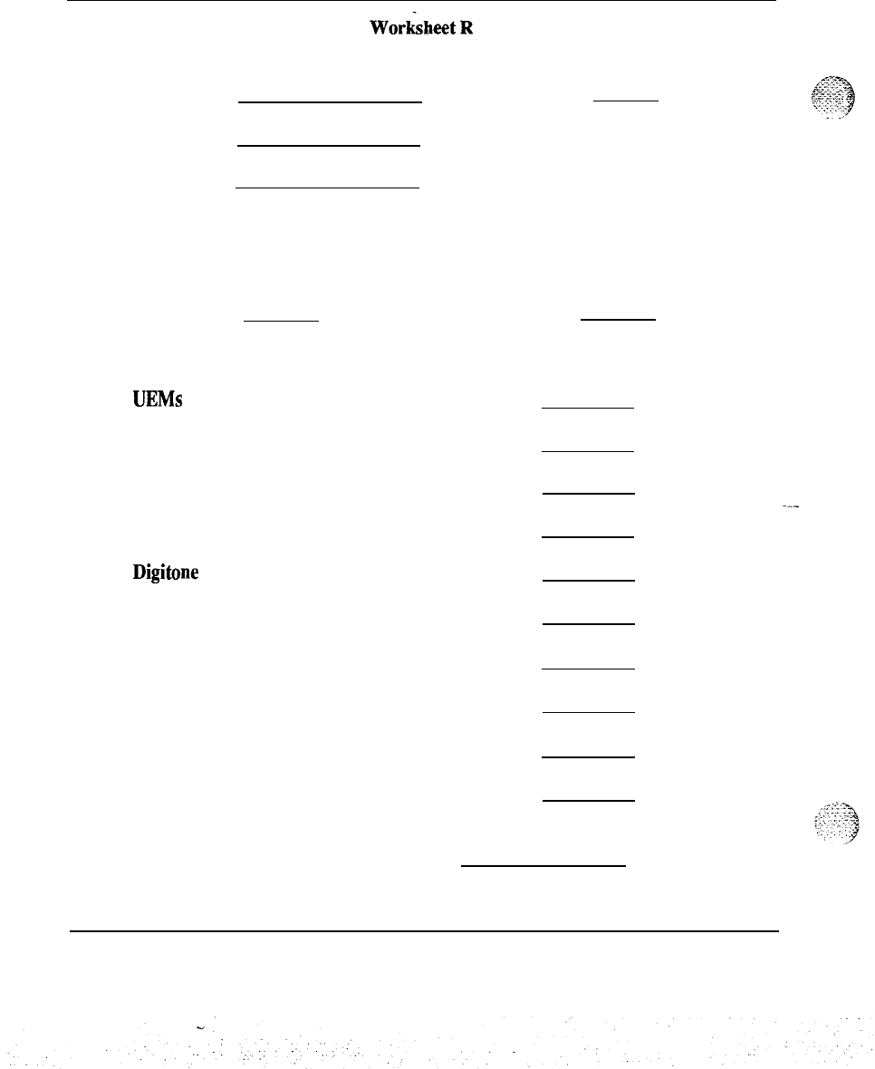
5-36 Worksheets
WorksheetR
SL-1 system assignment plan
Prepared by:
Date:
System:
Customer:
One sheet for each equipped voice loop.
Loop number Group number
UEMs
equipped
Trunks working
Trunks equipped
Consoles
Digitone receivers
2500 TN
500 TN
SL-1 TN
MAG assigned
Load capacity
Recommended assignment plan
System engineering 553-3001-151

Worksheets 537
‘WorksheetS
Multiple appearance group record
Prepared by:
Date:
System:
Customer:
Table S-l
Multiple appearance group record
MAG LP. EXT.
I
stat.
I
Set
I
System engineering 553-3001-151
2.

..A
6-1
Tables
Tables
6-1
Table 6-l : Trunk Traffic
6-1
Table 6-2: Trunk Traffic 6-3
Table 6-3: Digitone Receiver Requirements 6-5
Table 6-4 : Digitone Receiver Requirements 6-7
Table 6-5: Digitone Receiver Requirements 6-9
Table 6-6: Digitone Receiver Requirements 6-l 1
Table 6-7: Digitone Receiver Requirements 6-l 3
Table 6-8: Digitone Receiver Requirements 6-15
Table 6-9: Digitone Receiver Requirements 6-17
Table 6-l 0: TDS and CONF Loop Requirements 6-19
Table 6-l 1: Digitone Receiver Provisioning .6-20
System engineering 553-3001-l 51
-.
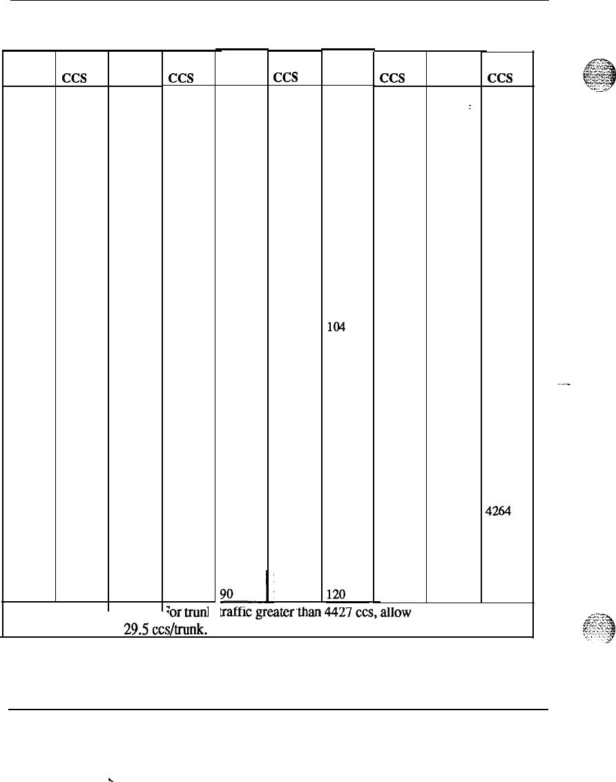
6-2 Tables
Table 6-1
Trunk traffic (Poisson 1% blocking)
TRKS
ccs
1
0.4
2
5.4
3
15.7
4
29.6
5
46.1
6
64
7
84
8
105
9
126
10
149
11
172
12
195
13
220
14
244
15
269
16
294
17
320
18
346
19
373
20 399
21
426
22 453
23
480
24 507
25
535
26 562
27
590
28
618
29 647
30 675
TRKS
ccs
31 703
32 732
33 760
34 789
35 818
36 847
37 876
38 905
39 935
40 964
41 993
42 1023
43 1052
44 1082
45 1112
46 1142
47
1171
48 1201
49 1231
50
1261
51 1291
52 1322
53
1352
54 1382
55 1412
56 1443
57 1473
58 1504
59 1534
60 1565
Note:
;or
trunl
TRKS
61
62
63
64
65
66
67
68
69
70
71
72
73
74
75
76
77
78
79
80
81
82
83
84
85
86
87
88
89
ccs
1595
1626
1657
1687
1718
1749
1780
1811
1842
1873
1904
1935
1966
1997
2028
2059
2091
2122
2153
2184
2215
2247
2278
2310
2341
2373
2404
2436
2467
2499
T
TRKS
ccs
TRKS
ccs
91
92
93
94
95
96
97
98
99
100
101
102
103
104
105
106
107
108
109
110
111
112
113
114
115
116
117
118
119
2530
2563
2594
2625
2657
2689
2721
2752
2784
2816
2847
2879
2910
2942
2974
3006
3038
3070
3102
3135
3166
3198
3230
3262
3294
3326
3359
3391
3424
3456
__
121 y
3488
122
3520
123 3552
124 3594
125 3616
126 3648
127 3681
128 3713
129 3746
130 3778
131 3810
132 3843
133 3875
134 3907
135 3939
136 3972
137 4004
138 4037
139 4070
140 4102
141 4134
142 4167
143 4199
144 4231
145 4264
146 4297
147 4329
148 4362
149 4395
150 4427
System engineering 553-3001-151
.
.
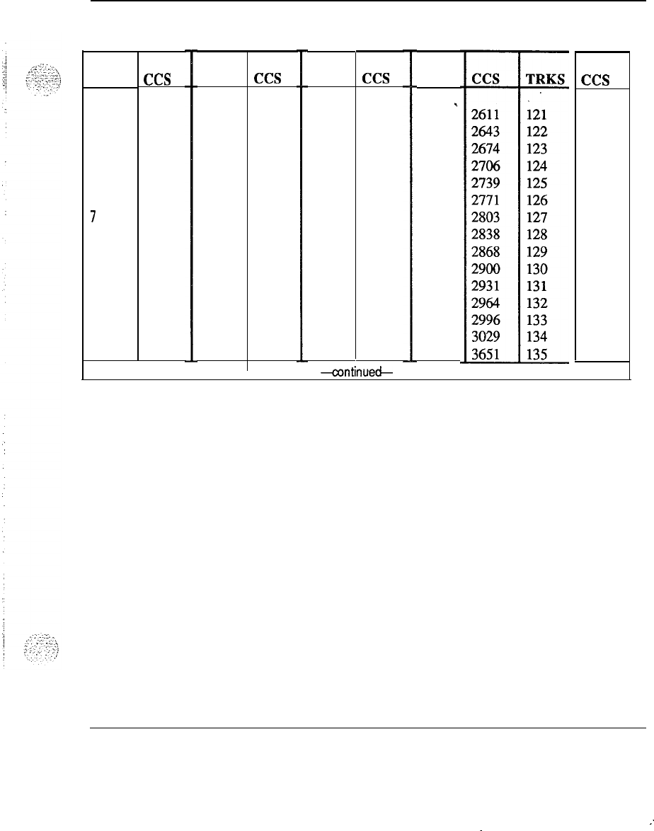
Tables 6-3
Table 6-2
Trunk traffic (Poisson 2% blocking)
TRKS
1
2
3
4
5
6
7
8
9
10
11
12
13
14
15
ccs
4
7.9
20.9
36.7
55.8
76.0
96.8
119
142
166
191
216
241
267
293
TRKS
ccs
31
32
33
34
35
36
37
38
39
40
41
42
43
44
45
744
773
803
832
862
892
922
952
982
1012
1042
1072
1103
1133
1164
TRKS
ccs
61
62
63
64
65
66
67
68
69
70
71
72
73
74
75
1659
1690
1722
1752
1784
1816
1817
1878
1910
1941
1973
2004
2036
2067
2099
-continueck
TRKS
91
-
92
93
94
95
96
97
98
99
100
101
102
103
104
105
ccs
3581
3614
3647
3679
3712
3745
3777
3810
3843
3875
3810
2941
2974
4007
4039
System engineering 553-3001-l 51
:
.
.
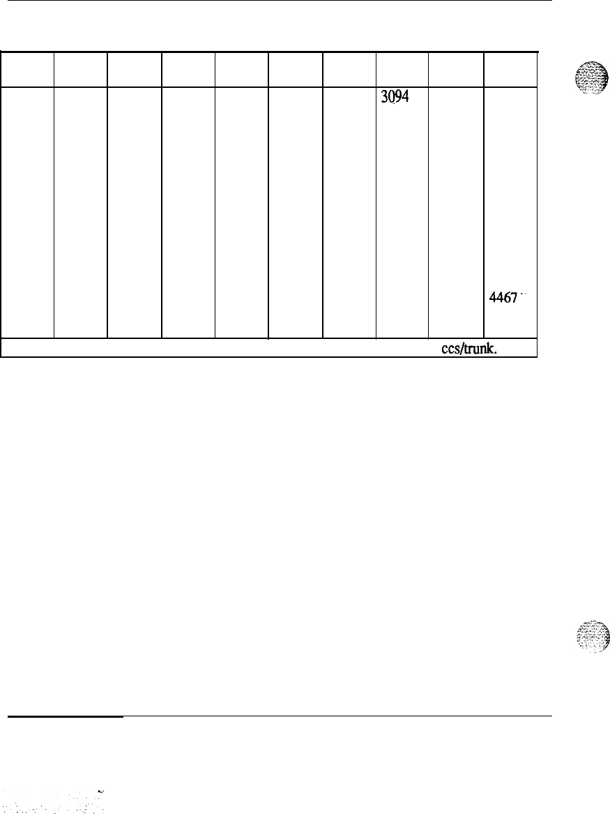
6-4 Tables
Table 6-2 continued
Trunk traffic (Poisson 2% blocking)
TRKS CCS TRKS CCS TRKS CCS TRKS CCS TRKS CCS
16
320 46
1194 76 2130 106 3094 136 4072
17
347 47
1125 77 2162
107
3126 137 4105
18
374 48
1255 78 2194 108 3158 138 4138
19
401 49
1286 79 2226
109
3190 139 4171
20
429 50
1317 80 2258 110 3223 140 4204
21
458 51
1348 81 2290
111
3255 141 4237
22
486 52
1374 82 2322 112 3288 142 4209
23
514 53
1352 83 2354
113
3321
143
4302
24
542 54
1441 84 2386
114
3353 144 4335
25
571 55
1472 85 2418 115 3386 145 4368
26
562 56
1503 86 2450 116 3418 146 4401
27
627 57
1534 87 2482
117
3451 147 4434
28
656 58
1565 88 2514 118 3483 148
4467’.
29
685 59
1596 89 3546
119
3516 149 4500
30
715 60
1627 90 2578 120 3548 150 4533
Note:
For trunk traffic greater than 4533 ccs, allow 30.2 ccs/trunk.
System engineering 553-3001-151
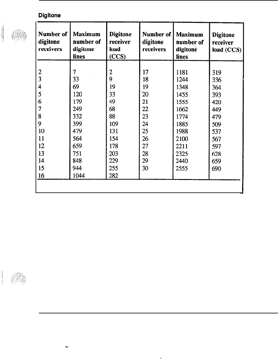
Tables 6-5
Table 6-3
Digitone receiver requirements
Nok: Refer to Section 3-15 for the Model assumptions for
this table.
System engineering 553-3001-151
.u
I
6-6 Tables
Table 6-4
Digitone receiver requirements
Number of Maximum Digitone Number of Maximum Digitone
digitone number of receiver load digitone number of receiver
load
receivers digitone line! (CCS) receivers digitohe lines
(C’CS)
2
3
4
5
6
7
8
9
10
11
12
13
14
15
16
2 2
17
843 253
21 7
18
920 276
52
15 19
996 299
90 27 20 1076 323
134 40 21 1153 346
183 55 22 1233 370
235
71
23 1316 395
293 88 24 13% 419
353 107 25 1480 444
416 126 26 1563
469
.-
483
145
27 1650 495
553 166 28 1733 520
623 187 29 1816 545
693 208 30 1903 571
770
1 231
Note:
Refer to Section 35 for the
Mod
assumptions
for this table.
.-__
System engineering 553-3001-151
-.
..:
:
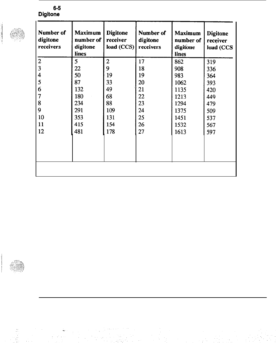
Table 6-5
Digitone receiver requirements
Tables 6-7
13
14
15
16
548 203 28 1697 628
618 229 29 1781 659
689 255 30 1864 690
762 282
Note: Refer to Section 3-15 for the Model assumptions for
this table.
System engineering 553-3001-151
6-8 Tables
Table 6-6
Digitone receiver requirements
Number of
Maximum
Digitone Number of
Maximum
Digitone
digitone
number of receiver
digitone
number of receiver
receivers digitone load (CCS) receivers digitone ‘load (CCS:
lines lines
24 2
17
683 253
318
7
18
745 276
441
15 19
808 299
5
72 27 20 872 323
6
109
40 21 935 346
7
148 55 22 1000 370
8193
71 23 1067 395
9240 88 24 1132 419
10
291 107 25 1200 444
11
340 126 26 1267 469
12
391
145
27 1337 495
13
448 166 28 1405 520
14
505
187
29 1472 545
15
562 208 30 1543 571
16 624 231
Note:
Refer to Section 3-15 for the Model assumptions for
this table.
-‘--‘--.
. . _
_
_.
.-..._
,.._
. . .
W...^
.~
-.
::
.;_.
,I
System engineering 553-3001-151
.
.
.:
:
:
I
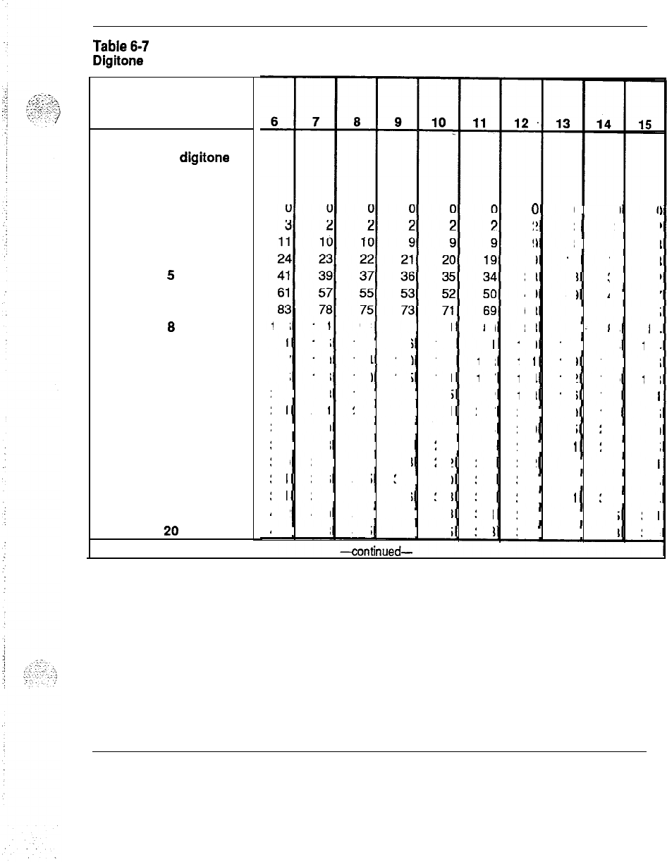
Tables 6-9
Table6-7
Digitone receiver load capacity in CCS
Average holding time in
seconds
Number of digitone
receivers
1
2
3
4
5
6
7
8
9
10
11
12
13
14
15
16
17
18
19
106
101 91
94 91
89
131
125
120 116
113
111
157 150 144 140 136 133
185 176 170 165
161
157
212 203 196 190 185
182
241 231
223 216 211
207
270 259 250 243 237 233
300 288 278 271 264 259
339
317 397 298
292 286
361
346 335
327 310
313
391
377 365 356
348 342
422 409
396 386 378
371
454 438
425
414 405
398
0
0 0
0
22
2 2
9
8 8 8
19
19
18 18
33 33
32 32
49 49
48 47
68
67 66 65
88
86
65 84
109
107 106
104
131
129
127 126
154 152 150 148
178 176 173
171
203 200
198 196
229 225
223 220
255 251 248 245
282
278 274 271
319 306 392 298
336 331 327 324
364 359 355
351
393 388 383
379
System engineering 553-3001-151
.
.
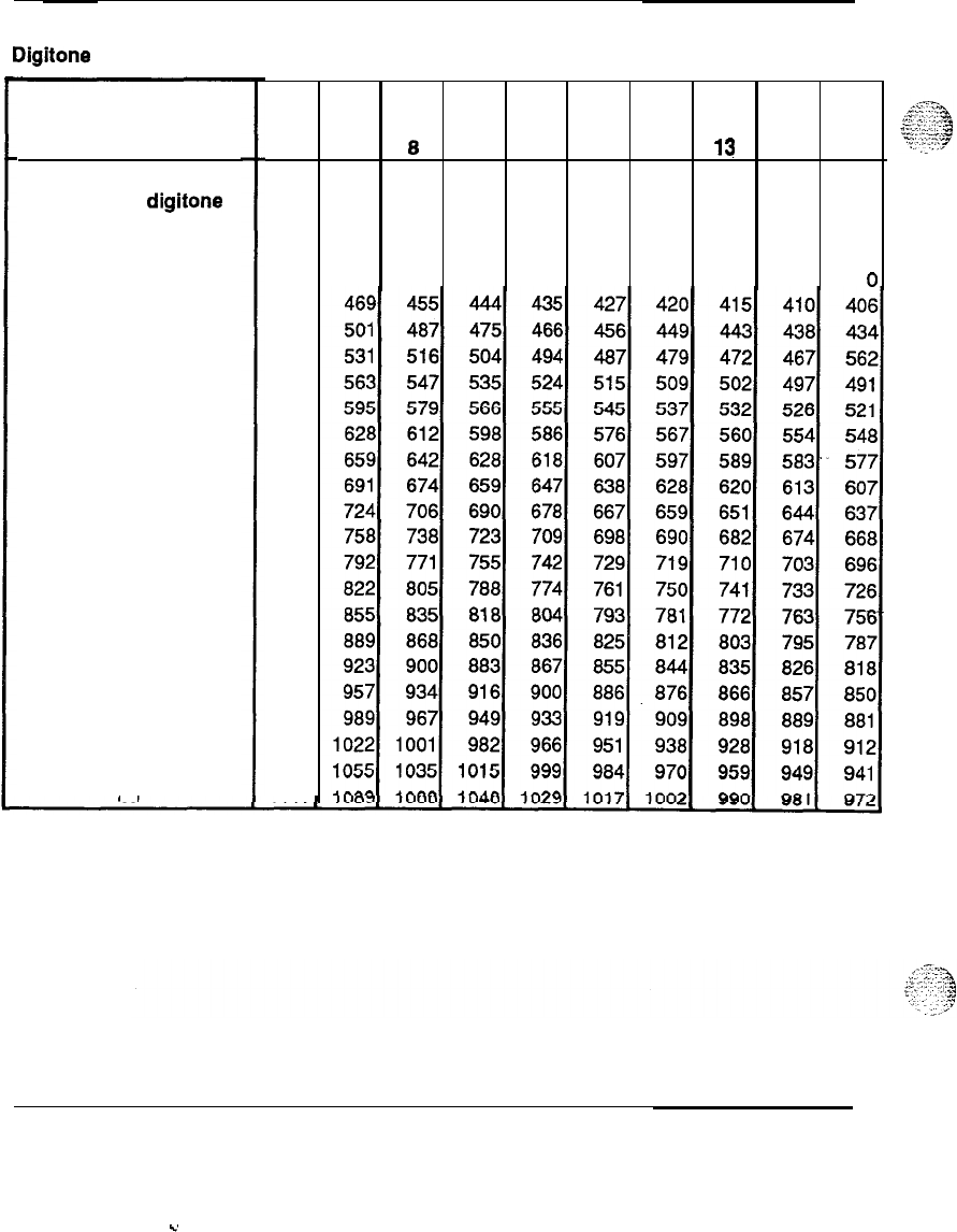
6-10 Tables
Table 6-7 continued
Digitone receiver load capacity in CCS
Average holding time in
seconds
Number Of digitone
receivers
21
22
23
24
25
26
27
28
29
30
31
32
33
34
35
36
37
38
39
40
6 7
89 10
11
12 13
.
14 15
0
0
00
000
0
0
0
487
517
550
583
615
647
680
714
746
779
813
847
882
913
947
981
1016
1051
1083
1117
System engineering 553-3001-151
C.
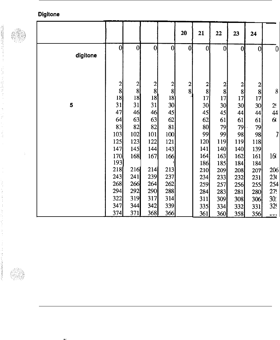
Tables 6-11
Table 6-8
Digitone receiver load capacity in CCS
Average holding time in
seconds
Number Of digitone
receivers
1
2
3
4
5
6
7
8
9
10
11
12
13
14
15
16
17
18
19
20
16 117
1
18
(
19
(
192 190 189
18
30
45
62
80
100
121
142
165
188
211
236
260
286
312
337
364
25
4
1’
2!
4
6(
71
9
111
131
16(
18:
20(
23(
25
27!
30:
32!
35’
L
System engineering 553-3001-151
D
2
B
7
3
4
3
3
7
3
3
3
3
5
3
1
a
5
a
5
-.
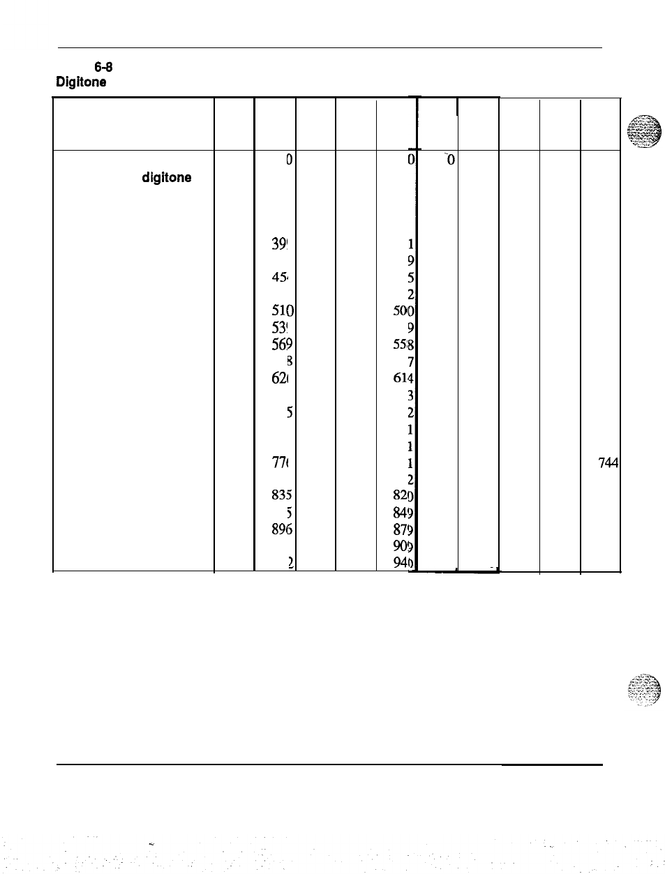
6-12 Tables
Table 6-8 continued
Digitone receiver load capacity in CCS
Average holding time in
seconds
Number of digitone
receivers
21
402
3919
396
393 39
22
431 42
7
424 421
41’
23
458
454
4
451 448
44
24
486
48:2
478 475
47:
25
514
5113
506 503 50
26
544
53!
9
535 532
52’
27
573
56!
9
565 561
55:
28
603
591
8
594 590 58
29
631 62i
5
622 618
614
30
660
65:
5
651 646
64:
31
690
68:
5
680 676
67:
32
720
711
5
710 705 70
33
751
741
5
740 735 73
34
782
77t
5
771 766 76
35
813 80
7
801
7%
79:
36
341 83!
5
829 824
82i
37
872
861
5
859 854
84!
38
902
89t
5
890 884
87!
39
934 92
7
921 914
90!
40
965 95:
1
952 945
94
16 17
18 19 20
0
1
0
0 0
’
I
21 22 23 24 2521 22 23 24 25
-0
0 0 0 0
-0
0 0 0 0
388 386 385 383 381388 386 385 383 381
416 414 412 410 409416 414 412 410 409
442 440 438 436 434442 440 438 436 434
470 467 465 463 461470 467 465 463 461
497 495 492 490 488497 495 492 490 488
526 523 521 518 516526 523 521 518 516
555 552 549 547 545555 552 549 547 545
584 581 578 576 573584 581 578 576 573
611 608 605 602 600611 608 605 602 600
639 636 633 631 628639 636 633 631 628
668 665 662 659 656668 665 662 659 656
698 694 691 688 686698 694 691 688 686
727 724 721 718 715727 724 721 718 715
757 754 750 747
744
757 754 750 747
744
788 784 780 777 774788 784 780 777 774
818 814 810 807 804818 814 810 807 804
845 841 837 834 831845 841 837 834 831
875 871 867 863 860875 871 867 863 860
905 901 897 893 890905 901 897 893 890
936 931
936 931 927 923 920
927 923 920
System engineering 553-3001-151
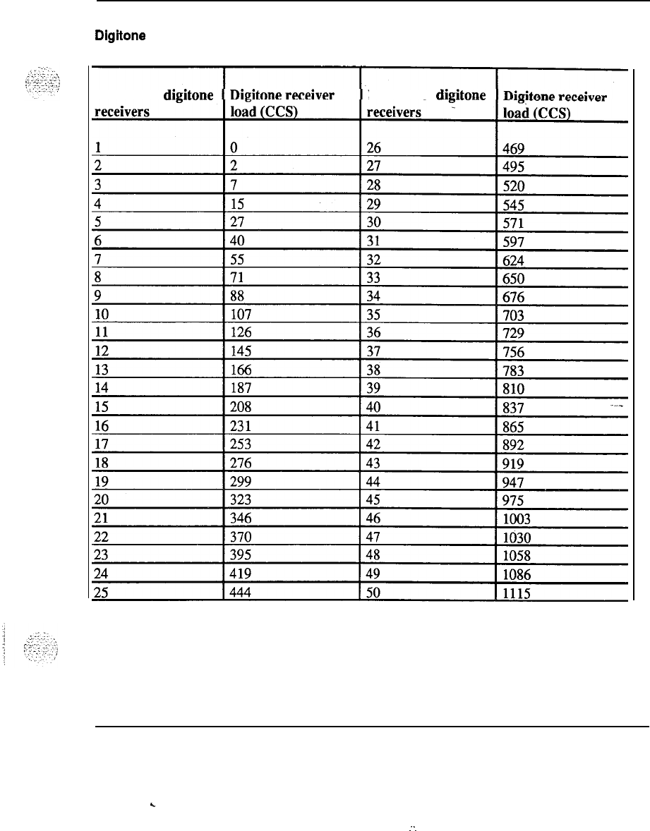
Tables 6-13
Table 6-9
Digitone receiver requirements
(Poisson 0.1% blocking)
Number of digitone Number of digitone
System engineering 553-3001-151
.
.
:
I
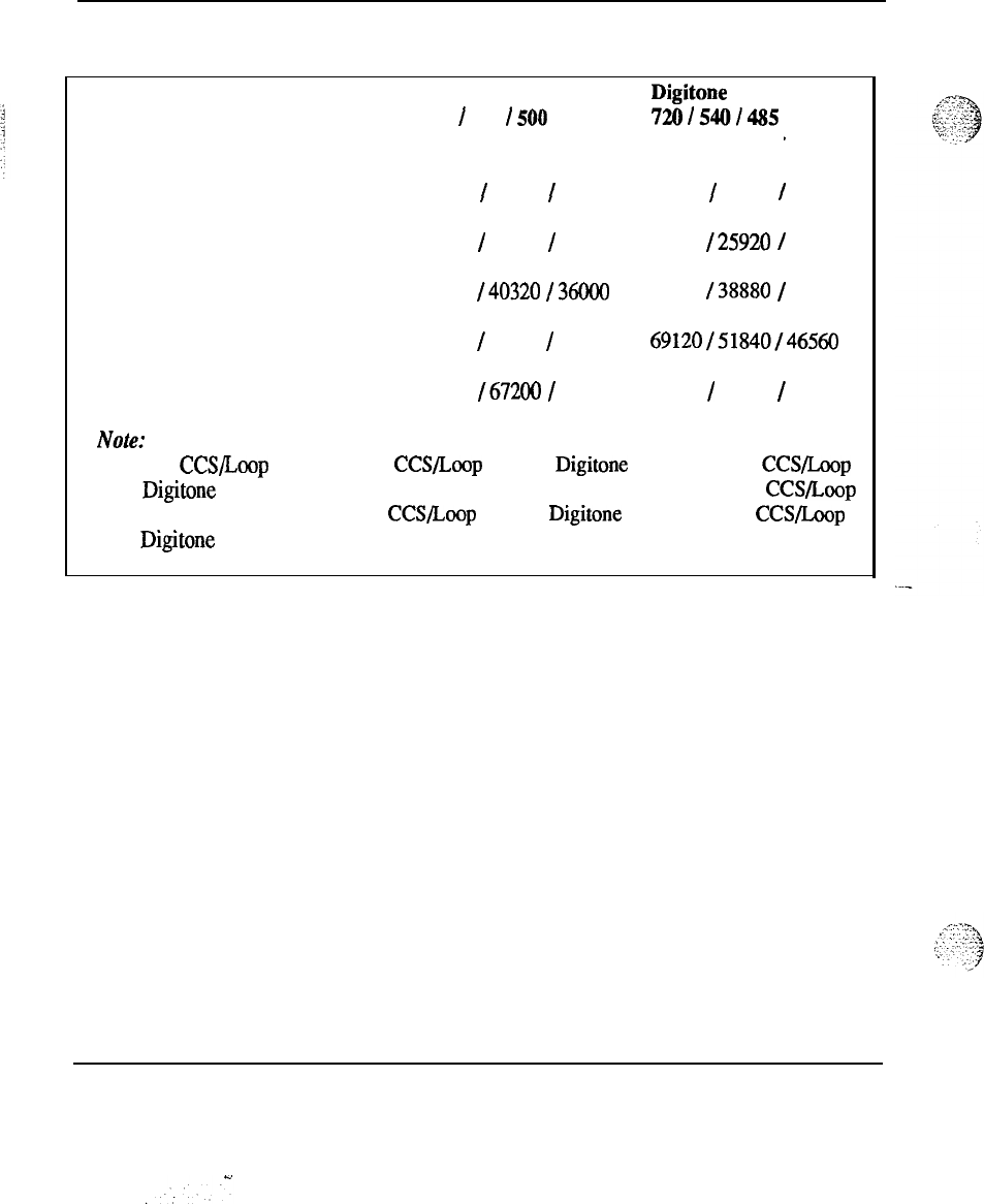
6-14 Tables
Table 6-10
Network group capacities
Number of Maximum number No figitonetrunks Digitone trunks
network
of
744
I
560
I
500
720/5401485
groups voice loops CCS per loop CCS per loop
1
1
24 17850
/
13440
/
12000 17280
/
12960
/
11640
248 35700
/
26880
/
24000 34560
I25920
/
23280
3
72 53550
I40320
I36000
51840 138880
/
34920
496 71400
/
53760
/
48000
69120/51840/46560
5 120 89250
I67200
I
60000 86400
/
64800
/
58200
Note:
This table is based on an 85% utilization level. The 17850 CCS limit used above is
based on CCS/Loop figures of 744 CCS/Loop with no Digitone trunks and 720 CCS/Loop
with
Digitone
trunks. This constitutes an 85% utilization level of the maximum CCS/Loop
of the current system which is 875 CCS/Loop with no Digitone trunks and 848 CCS/Loop
with
Digitone
trunks and with the use of a Superloop Network Card.
System engineering 553-3001-151
Tables 6-15
..:
.-
._.*:
_-
..-I.
_;:
!,;z‘+
.f
,..,
;;
-.’
..’
.,:.,
Table 6-10
TDS and CONF loop requirements
Network loops Tone and Digit Conference loops
required at 2 years Switch required
loops required
1-12
1 1
13-24
22
25-36
3 3
37-48
4 4
49-60
5 5
61-72 6 6
73-84
7
7
85-96
8
8
97- 108
9 9
m-120
10 10
System engineering 553-3001-l 51
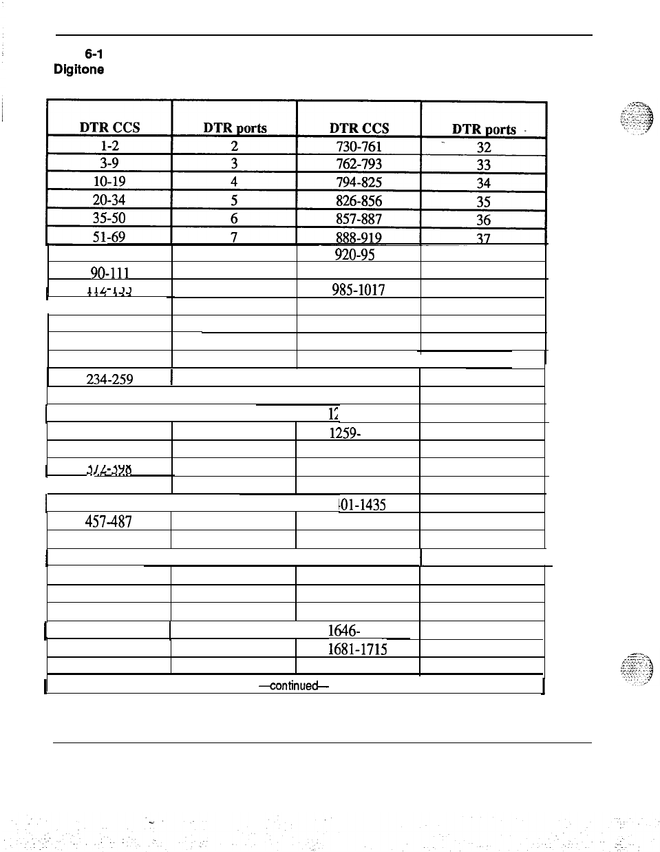
6-16 Tables
Table
6-l
1
Digitone receiver provisioning
(assumes 1 l-second holding time)
70-89
8920-9s 1 38
go-111 9952-984 39
I
11,l
1’12
11/L-121)
10 985-1017 40
I
134-157
11
1018-1050 41
12 1051-1084 42
43
158-182
183-207
13
1085-1118
208-233
14
1119-1153
1
44
234-259
I
15
I
1154-1188 45
260-286 16 1189-1223 46
I
287-3 13
I
17
I
1;
!24-1258 47
314-342
18
1259- 1293 48
343-371
19
1294-1329 49
I
r)rm
Plnn
3
IL-3YU
20 1330-1365 50
I
399-427 21 1366-1400
51
I
428-456
I
22
I
14
101-1435
52
457487
23 1436-1470 53
488-515 24 1471-1505 54
I
516-545
I
25
I
1506-1540
1
551
546-576 26 1541-1575 56
577-607 27 1576-1610 57
608-638 28 1611-1645 58
I
639-667
!
29
I
1646- 1680
59
668-698
30 1681-1715 60
699-729
31
1716-1750
61
I
-continued-
System engineering 553-3001-151
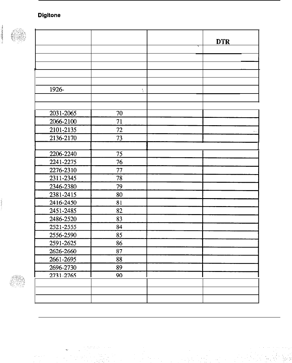
Tables
6-17
Table 6-11 continued
Digitone receiver provisioning
(assumes 11-second holding time)
DTR CCS DTR
ports
1751-1785
62
DTR CCS
2871-2905
-
DTR
ports
94
1786-1820 63 2906-2940 95
1821-1855 64
294 l-2975
I
96
I
1856-1890
65 2976-3010 97
1891-1925 66 3011-3045
98
1926- 1960
67
1
3046-3080 99
1961-1995
68
3081-3115
100
1996-2030 69 3116-3465
101
I
I
2171-2205 74
I1
2766-2800
91
2801-2835 92
2X36-2870 93
System engineering 553-3001-151

SL-1
System options 21,51,61,71
System engineering
Copyright
0
1990 Northern Telecom
All rights reserved.
Information subject to change without notice.
Release 1 .O
Standard
January 29,199O
Printed in U.S.A.
SL-1
Generic Xl 1
Memory calculations
Standard, release 15


SL-1
Generic Xl 1
Memory calculations
Publication number: 553-2201-151 Appendix 1
Product release: Xl 1 release 15
Document release: 1 .O
Document status: Standard
Date: December
20,1989
0
1984 Northern
Telecom
All rights reserved.
Memory calculations 553-2201-151 Appendix 1
C.
ii
Revision history
December 1989
Standard, release 1.0. This Publication is reissued as the Standard version
for Relaes 15. Changes are marked with R15.
Memory calculations 553-2201-l 51 Appendix 1
c
Contents
.
.
.
Ill
General
Memory description 3
Memory Generic 711 (S and MS) 5
Memory Generics 811 and 911 (N and XN)
5
Memory Generics 1011 (ST)
5
Memory Generics 1111,1211, and 1311 (NT, XT, and RT)
5
Templates
6
Memory calculations
Package dependencies
Program store requirements
Unprotected data storage requirements
Protected data storage requirements
9
10
..-_ 11
85
115
List of terms 163
Memory calculations 553-2201-151 Appendix 1
..
:
:
.
.

iv Contents
Memory calculations 553-2201-151 Appendix 1
1
General
.
.,
!
,:-,.
:“‘.:.
.
^
(
.,../
This Appendix provides memory information relating to the SL-1 Integrated
Services Network
(EN).
Engineering and assigning of equipment
(553-2201-151) provides
provisioning information and the associated data worksheets for a complete
system. For Generic Xl 1,
Engineering and assigning of equipment (553-
2201-151) directs the user to this Appendix for specific memory
c&.&ion
information. Apply this information in worksheets G, H, I of that document
for the machine types in Table 1.
Use these numbers to identify machine types in the following tables.
Note : The memory calculations for the RT (13 11) are the same as-for
NT(llll).
Table 1
Machine type designators
Machine Code System
type number ,option
MS/S =
711
N
=
811
XN
=
911
ST
=
1011 21
NT
=1111
51161
XT
=
1211 71
RT
E
1311
Memory calculations 553-2201-151 Appendix 1

2 General
Memory calculations 553-2201-151 Appendix 1
.
.
.:
.-
-.
3
Memory description
Software and office data are stored in a read/write Random Access Memory
(RAM). The RAM is organized into modules of 128K, 192K, 256K, 512K
or 768K by
16bit
words, or 24-bit words for NT, RT, and XT machines in
Release 12 and later. Memory size depends on the features programmed
into the machine and the number and type of stations served. The memory
module pack(s) are mounted in the CE shelf. The following table shows the
valid hardware configuration for the various SL-1 systems.
..
Release 15 introduces other System Options, whose memory calculations
coincide with the following current machine types:
-
System option 21 has the same.memory capacity as the 1011 machine
(ST)
type
---
-
System options 51, and 61 have the same memory capacity as the 1111
machine (NT) type
-
System option 71 has the same memory capacity as the 1211 machine
(XT)
type
Memory calculations 553-2201-I 51 Appendix 1
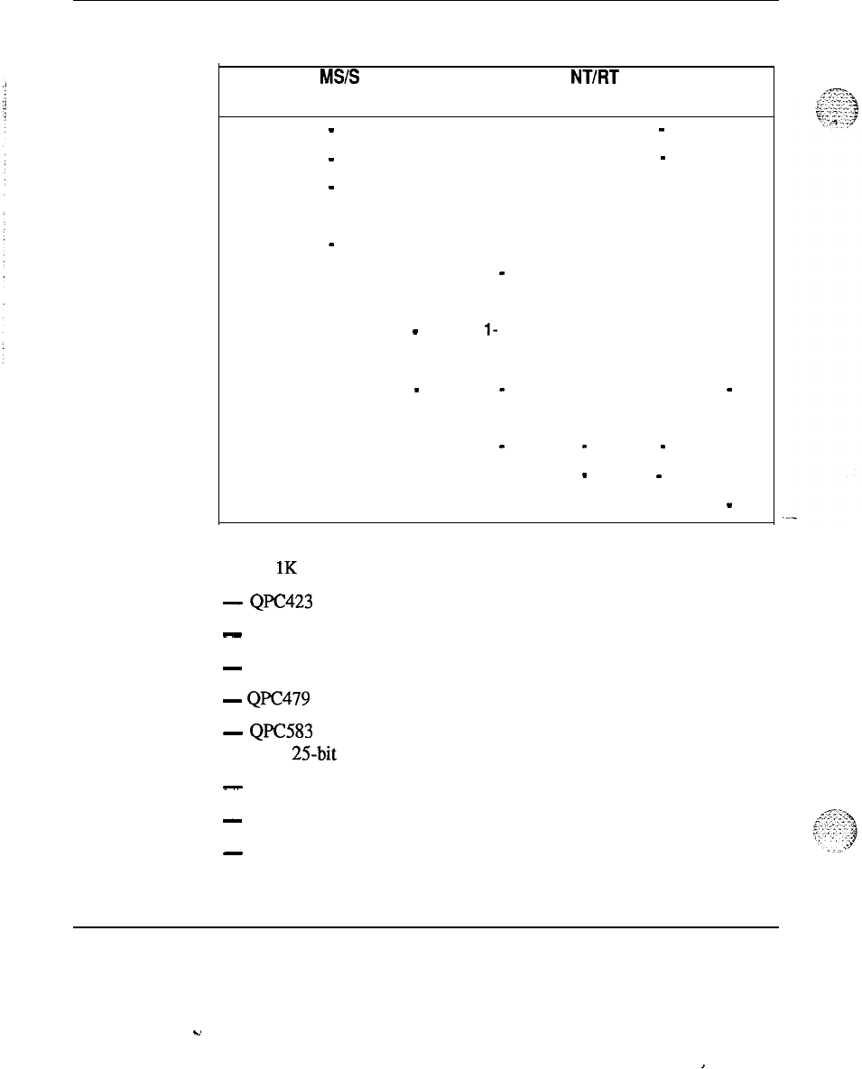
4 Memory description
Table 2
QPC memory module packs per system-
Memory MS/S
N
XN NT/FIT
XT ST
size
128K
1
-
478
l-479
1
-
479
192K
1
-
423
l-426
1
-
426
256K 2
-
478
2-479 2-479
OR
1
-
674
320K
l-426
1
-
478
+ +
1
-
479
l-
479
384K
2-426 2-426
512K 1
-
672 1
-
672
1
-
673
576K
3-426
768K 4
-
426
1
-
583 1
-
583
1536K
1
-
583
2
-
583
2304K 3
-
583
Note : 1K = 1024 words. Storage capacity of the:
-
QpC423 memory circuit pack is 192 x 1024 or 196,608 words
-
QPC426 memory circuit pack is 192 x 1024 or 196,608 words
-
QPC478 memory circuit pack is 128 x 1024 or 131,072 words
-
QpC479 memory circuit pack is 128 x 1024 or 13 1,072 words
-
QPC583 memory circuit pack is 768 x 1024 or 786,432 words,
with
25bit
words for NT and XT machines
-
QPC672 memory circuit pack is 512 x 1024 or 524,288 words
-
QPC673 memory circuit pack is 512 x 1024 or 524,288 words
-
QPC674 memory circuit pack is 256 x 1024 or 262,144 words
Memory calculations 553-2201-151 Appendix 1
..s
I

Memory description 5
Memory Generic 711 (S
and
MS)
The memory requirements for a Generic 7 11 system consists of a Read
Only Memory (ROM) circuit pack and RAM circuit pack(s). The memory
system is divided into pages.
The unprotected and protected data stores are usually assigned to pages 0
and 1.
The bottom 8K words of page 2 are replaced with the QPC486 ROM pack.
The remaining top words of page 2 are assigned to program store.
Page 3 (Input/Output memory) is not assigned to a QPC478 module and
page 4 is not used.
Additional pages of program store are provided as required, by RAM pack
addition or rearrangement.
Configuration Overlay LD 17 is used to assign the RAM type or‘
combination of types for data and program store to a system (see 553-3001-
400).
Memory Generics 811 and 911 (N and XN)
Software and office data for Generics 8 11 and 9 11 are stored in a
RAM
(as
for Generic 7 11) except that QPC426 and/or QPC479 modules (or a
QPC672) are used.
The ROM for Generic 8 11 is contained in a QPC486 pack while the ROM
for Generic 9 11 is part of the QPC443 Control and Timing pack.
Memory Generics 1011 (ST)
Software and office data for Generic 1011 system are stored in a RAM (as
for Generic 7 11) except that QPC673 (with error correction) is used.
The ROM for Generic 1011 is contained in QPC717 ROM pack which
connects to the QPC687 CPU pack.
Memory Generics 1111,1211, and 1311 (NT, XT, and RT)
Software and office data for Generic 1111,1211, and 13 11 systems are
stored in a RAM (as for Generic 711) except that QPC583 modules, with
24-bit addressing, are used.
Memory calculations 553-2201-l 51 Appendix 1
6 Memory description
The ROM for Generic 1111; 1211, and 13 11 is contained in a QPC579 CPU
Function Unit.
Templates
A template is a map of the pattern of keys/features assigned to a telephone,
The protected data structure for the SL- 1 NE-500/2500 and digital
telephones is based on the concept of shared templates. For example, if two
or more telephones have identical key/feature layouts, then the data
regarding this layout is contained in a single template, thereby reducing the
storage required for data description.
The operation of the template mechanism is internal and is transparent to
the user. Templates are created automatically either by service change
programs or by the sysload program at system startup. The data print
program (Overlay 20) of 553-3001-400 has been extended to assist in
optimizing template usage. The program can print:
-
individual templates or all templates in the system.
-
the number of telephones using a particular template.
-
the Terminal Numbers (TNs) using a template.
-
the total number of templates defined and the number of templates used
by at least one telephone.
..-_
IVole
:
A large number of telephones clustered around a relative small
number of templates indicates efficient use of templates.
When data is entered into the system, use the following guidelines to
maximize the protected memory savings provided by the template
mechanisms.
(a) If two or more telephones have the same functions defined, they should,
if possible, have the same key/feature layout assigned. This ensures
that all such telephones and add-on modules share the same template.
(b)
For telephones that have the same functions defined but their auto-dial
and/or call-forward features have different number sizes, it is less
expensive (in terms of memory) to make the sizes of the numbers equal
rather than assign the telephones to different templates. The rule to be
used
is
that a new template requires at least 12 words of protected data
for SL-1 telephone sets and four words for 500/2500 telephones,
whereas four extra digits use only 1 word.
Memory calculations 553-2201-l 51 Appendix 1
c.

Memory description 7
(c) Use Overlay 20 of
553-300140
to m&ntain a current list of all
templates defined in the system. Consult this list whenever service
change of telephones is to be performed.
Memory calculations 553-2201-151 Appendix 1
.
.

8 Memory description
---
Memory calculations 553-2201-151 Appendix 1
.
.

9
_-
:
:
:.::.
::
!
,
.:.
.
-,
.,
,
,,
.,
:
Memory calculations
The memory requirement for Xl 1 Generic must be calculated individually
using the following tables:
Table Storage
3Software Program
4Unprotected Data
5Protected Data
Record the memory requirements on worksheets G, H and I and add
this-
data to the other completed main practice worksheets to compile the total
provisioning data for the SL- 1 system.
Note: The memory requirement figures shown in the tables are based
on the following software releases:
711 Releases 4 through 13
811 Releases 4 through 14
911 Releases 4 through 14
1011 Releases 9 through 15
1111/1211 Releases 8 through 15
1311 Releases 12 through 15
Note
1:711,8
11 and 911 Release 6 information is included in Release
7.
Memory calculations 553-2201-151 Appendix 1
-
.
.

10 Memory calculations
Note 2:The
memory calculations for the RT (1311) machine are the
same as for the NT (1111) machine type.
The absence of Generic release indicator R4, R5, or R7 in
the Version
column indicates the storage words for the associated program applies to all
Generic releases.
Package dependencies
Each Generic contains a basic feature group (always provided) to which
optional features can be added. For a complete list of the packages
available and their related package dependencies, refer
to Equipment
identification and ordering (U.S.)
(553-2201-153).
Memory calculations 553-2201-l 51 Appendix 1
.u
.:
.‘.
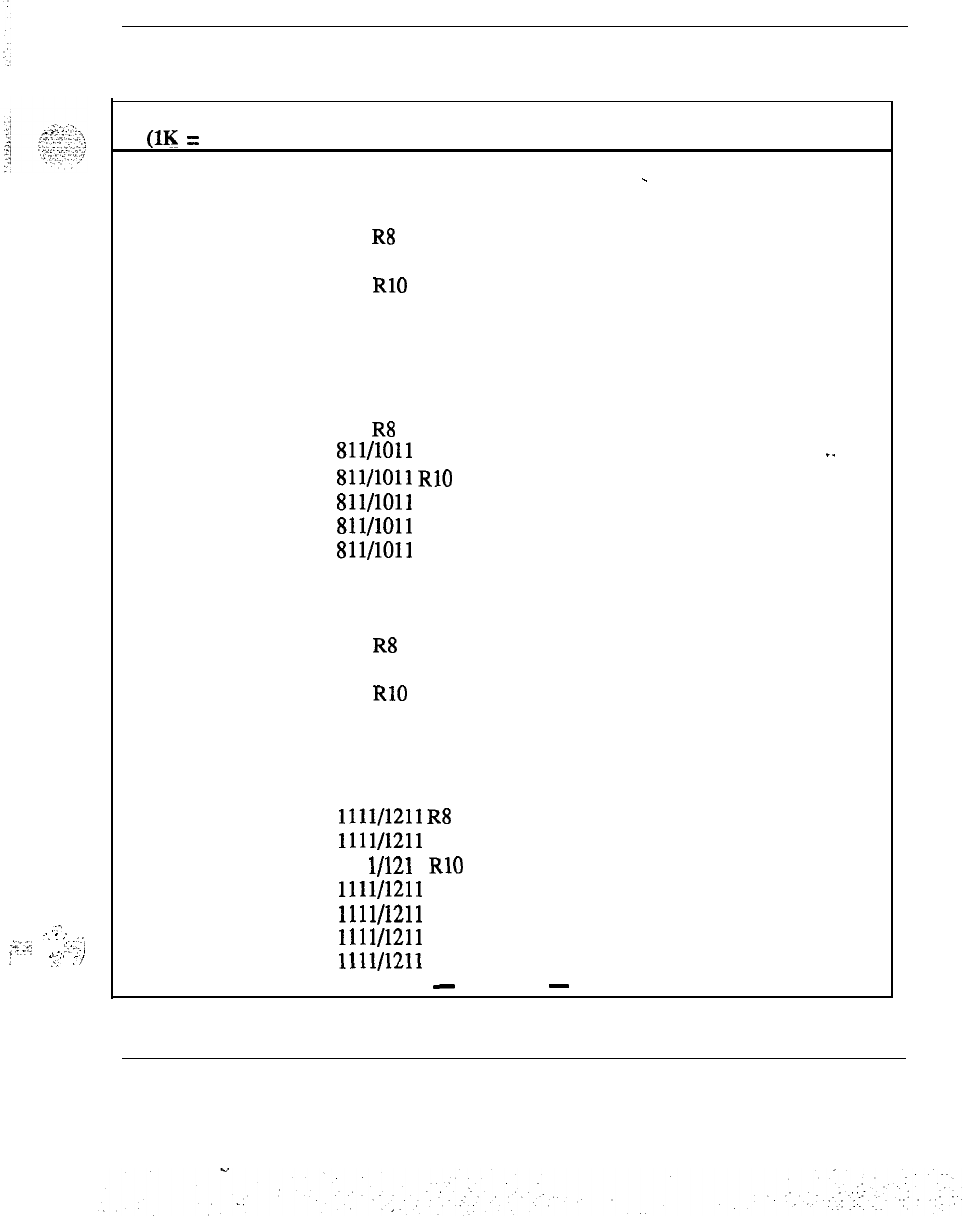
Table 3
Software program storage requirements
:
,..,
!
-..
:
.:.
:L.-,T
,‘,,.:_j;
i_,-.
.:
,.;
./
Memory calculations 11
Program Version Storage in Ks Comments
(1K = 1024 words)
Resident (Basic) 711 R4 73.88
711 R5 77.04
-
711 R7 85.59
711 R8 87.61
711 R9 90.24
711 RlO 96.70
711 R12 112.74
711 R13 122.62
811 R4 77.15
811 R5 81.96
811 R7 89.67
811 R8 91.10
811/1011
R9
95.31
_.
811/1011
RIO 102.02
Sll/lOll
R12
116.75
811/1011 R13 126.90
811/1011 R14 136.36
911 R4 75.76
911 R5 81.65
911 R7 89.30
911 R8 90.62
911 R9 92.51
911 RlO 73.53
911 R12 111.03
911 R13 121.59
911 R14 136.06
1011 R15 158.77
1111/1211
R8 68.46
1111/1211
R9
70.02
111 l/121 1 RlO 73.53
1111/1211
R12
84.23
1111/1211 R13 87.84
1111/1211 R14 94.62
1111/1211 R15 122.20
-
continued
-
Memory calculations 553-2201-l 51 Appendix 1
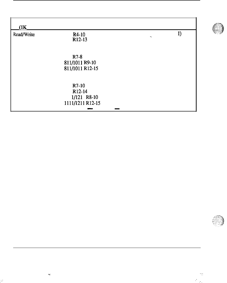
12
Memory calculations
Table 3
Software program storage requirements (continued)
Program Version Storage in K
S
Comments
(1K = 1024 words)
Read/Write Firmware 711 R4-10 0.74 (Note
1)
-
711 R12-13 0.36
811 R4 0.34
811 R5 0.35
811 R7-8 0.35
811/1011
R9-10 0.39
811/1011
R12-15 0.55
911 R4 0.40
911 R5 0.77
911 R7-10 0.77
911 R12-14 Note 1
111 l/121 1 R8-10 0.96
1111/1211
R12-15 Note 1
-
continued
-
Memory calculations 553-2201-151 Appendix 1
s.
x:
:.:
:
.-
:
.
.
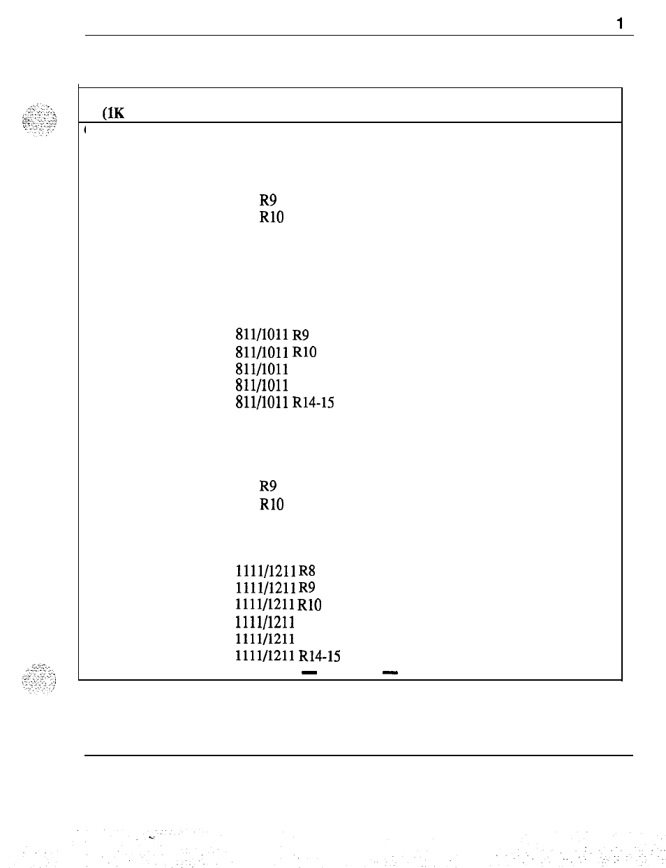
Memory calculations
I
3
Table 3
Software program storage requirements (continued)
Program Version Storage in K
S
Comments
UK
= 1024 words)
Overlay Area 711 R4 10.58
711 R5 15.74‘
711 R7 16.46
711 R8 16.92
711 R9 16.96
711 RlO 17.12
711 R12 18.07
711 R13 10.75
811 R4 11.00
811 R5 15.58
811 R7 16.46
811 R8 16.94
811/1011
R9 17.42
.
811/1011
RlO 17.43
811/1011
R12
18.07
811/1011 R13 10.75
Sll/lOll
R14-15 20.51
911 R4 11.00
911 R5 15.58
911 R7 16.46
911 R8 16.94
911 R9 17.42
911 RlO 17.43
911 R12 18.07
911 R13 25.41
911 R14 20.51
1111/1211
R8 16.46
1111/1211
R9 17.42
1111/1211
RlO 26.14
1111/1211 R12 27.10
1111/1211 R13 10.60
1111/1211
R14-15 30.76
-
continued
-
Memory calculations 553-2201-151 Appendix 1
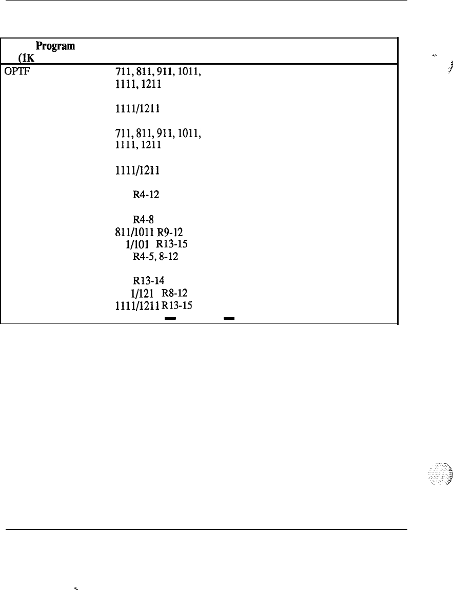
Table 3
Software program storage requirements (continued)
PrOgWll
Version Storage in K
S
Comments
(1K = 1024 words)
OF-IF
711,811,911,1011,
0
All
Releases
1111,121l
1011 R15 17.67
1111/1211 12.58
CUST
711,811,911,1011,
1111,121l
1011 R15
1111/1211 R15
0
9.19
6.38
All Releases
AIOD 711 R4-12 0.88
711 R13
0.91
811 R4-8 0.88
.
811/1011
R9-12 0.88
81 l/101 1 R13-15 0.91
911
R4-5,8-12
0.87
911 R7 0.86
911 R13-14 0.90
111 l/121 1 R8-12 0.65
1111/1211
R13-15 0.66
-
continued
-
-..
I
3
14 Memory calculations
Memory calculations 553-2201-151 Appendix 1
.
.
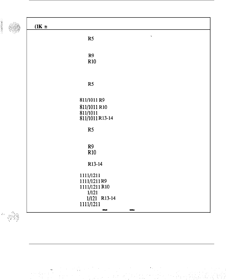
:,
_..
‘...
.:‘;;.:;::
:;::
I.
.,,
..s.
,.,!
-I
_’
Memory calculations 15
Table 3
Software program storage requirements (continued)
Program Version Storage in K
S
Comments
(1K = 1024 words)
CDR 711 R4 1.77
711 RS
-
1.80
711 R7 1.94
711 R8 1.99
711 R9 2.05
711
RlO 2.20
711 R12 2.38
711 R13 2.47
811 R4 1.77
811 R5 1.79
811 R7 1.94
811 R8 1.98
811/1011
R9 2.05
.
811/1011
RlO 2.20
811/1011
R12
2.38
811/1011
R13-14 2.47
911 R4 1.74
911
R5 1.77
911 R7 1.91
911 R8 1.95
911
R9 2.02
911
RlO 2.17
911 R12 2.35
911 R13-14 2.45
1011 R15 2.48
1111/1211
R8
1.50
1111/1211
R9 1.55
1111/1211
RlO 1.67
111 l/121 1 R12 1.80
111 l/121 1 R13-14 1.75
1111/1211
R15
1.76
-
continued
-
Memory calculations 553-2201-l 51 Appendix 1
16 Memory calculations
Table 3
Software program storage requirements (continued)
Program Version Storage in KSComments
(1K = 1024 words)
CDR TTY 711 R4 0.56
711 RS 0.57
-
711 R7 0.59
711 R8 0.71
711 R9 0.72
711 RlO 0.99
711 R12 1.07
711 R13 1.16
811
R4,5
0.56
811 R7 0.59
811 R8 0.71
811 R9 0.72
811 RlO 0.99
811/1011 R12 1.07
811/1011
R13-15 1.16
911
R4,5
0.56
911 R7 0.59
911 R8 0.70
911 R9 0.72
911 RlO 0.98
911 R12 1.06
911 R13-14 1.14
1111/1211 R8 0.54
1111/1211
R9 0.55
1111/1211
RlO 0.76
1111/1211 R12 0.82
1111/1211
R13-15 0.83
-
continued
-
Memory calculations 553-2201-151 Appendix 1
Table 3
Software program storage requirements (continued)
::.
:.
1....
/:_
. .
:.;
Memory calculations
17
Program Version Storage in K
S
Comments
(1K = 1024 words)
CDR CLNK 711 R4-5 0.56_
711 R7-9 0.59
711 RlO 0.66
711 R12 0.69
711 R13 0.81
811 R4-5 0.56
811 R7-8 0.59
Sll/lOll
R9
0.59
811/1011
RlO 0.66
811/1011
R12
0.69
811/1011 R13 0.81
811/1011
R14-15 0.89
911 R4 0.56
911 R5 0.57
911 R7-9 0.59
911 RlO 0.66
911 R12 0.70
911 R13 0.82
911 R14 0.90
1111/1211
R8-9 0.46
1111/1211
RlO 0.51
1111/1211 R12 0.53
1111/1211 R13 0.58
111 l/121 1 R14-15
0.64
-
continued
-
Memory calculations 553-2201-151 Appendix 1
.
.
18 Memory calculations
Table 3
Software program storage requirements (continued)
PrOgEUU
Version Storage iu K
S
Comments
(1K = 1024 words)
RAN 711 R4 1.34
711 R5
1.34
-
711 R7-8 1.36
711
R9
1.41
711 RlO-12 1.49
711 R13 1.55
811 R4 1.33
811 R5 1.34
811 R7-8 1.36
811/1011
R9 1.40
81 l/101 1 RlO-12 1.49
811/1011
R13
1.55
811/1011
R14
1.54
911 R4-5
1.31
911 R7 1.36
911 R8 1.34
911 R9 1.38
911 RlO 1.46
911 R12 1.47
911
R13-14 1.53
1011 R15 1.60
1111/1211
R8
1.03
1111/1211
R9 1.07
1111/1211
RlO 1.12
1111/1211
Rll
1.13
1111/1211
R13-14
1.11
1111/1211
R14
1.15
-
continued
-
Memory calculations 553-2201-151 Appendix 1
.
.
Memory calculations 19
Table 3
Software program storage requirements (continued)
Program
Version
Storage in
K
S
Comments
(1K = 1024 words)
TAD 711 R4-5 0.71
DNDI
711 R7-12 0.72
-
711 R13 0.76
811 R4-5 0.71
811 R7-8 0.72
811/1011
R9-12 0.72
81 l/1011 R13-15 0.76
911R4-5
0.72
911 R7-12 0.73
911 R13-14 0.77
1111/1211
R8-12 0.54
1111/1211
R13-15 0.56
. .
711
R4-9 0.39
711 RlO 0.40
711 R12 0.42
711 R13 0.40
811 R4-8 0.39
811/1011
R9 0.39
811/1011
RlO 0.40
81 l/101 1 R12 0.42
811/1011 R13 0.40
81 l/101 1 R14 0.42
911
R4-9 0.38
911 RlO 0.39
911 R12 0.41
911 R13 0.39
911 R14 0.41
1011 R15 0.43
111 l/121 1 RS-10 0.29
1111/1211
R12
0.30
1111/1211 R13 0.28
1111/1211 R14 0.30
1111/1211 R15 0.30
-
continued
-
Memory calculations 553-2201-l 51 Appendix 1

20 Memory calculations
Table 3
Software program storage requirements (continued)
Program Version Storage in K
S
Comments
(1K = 1024 words)
EES 711 R4 0.60
711 R5
0.79
-
711 R7 0.76
711 R8 0.75
711 R9 0.79
711 RlO 0.81
711 R12 0.83
711 R13 0.87
811 R4 0.60
811 R5 0.79
811 R7-8 0.76
81 l/101 1 R9 0.81
81 l/101 1 RlO 0.83
Sll/lOll
R12
0.85
811/1011 R13 0.89
811/1011 R14 0.91
911 R4 0.60
911 R5 0.78
911 R7-8 0.75
911 R9 0.80
911 RlO 0.82
911 R12 0.84
911 R13 0.88
911 R14 0.90
1011 R15 1.00
1111/1211 R8 0.54
1111/1211
R9 0.58
1111/1211
RlO 0.59
1111/1211
R12-13 0.61
111 l/121 1 R14 0.63
1111/1211 R15 0.69
711,811,911,1011,
0All Releases.
1111,121l
-
continued
-
Memory calculations 553-2201-151 Appendix 1
Table 3
Software program storage requirements (continued)
Memory calculations
21
Program Version Storage in K
S
Comments
(1K = 1024 words)
711 R4-9 1.54
711 RlO 1.56
711 R12 1.59
711 R13 1.65
811 R4-8 1.53
81 l/1011 R9 1.53
81 l/101 1 RlO 1.55
81 l/1011 R12- 1.58
811/1011 R13 1.64
811/1011 R14 1.66
911 R4 1.52
911 R5 1.52
911 R7-9 1.51
. .
911 RlO 1.53
911 R12 1.57
911 R13 1.62
911 R14 1.64
1011 R15 1.74
111 l/121 1 R8-9 1.17
---
1111/1211
RlO 1.19
1111/1211 R12
1.21
1111/1211 R13 1.19
1111/1211 R14 1.21
1111/1211 R15 1.26
-
continued
-
Memory calculations 553-2201-151 Appendix 1
s.
:
:
22 Memory calculations
Table 3
Software program storage requirements (continued)
Program Version Storage in K
S
Comments
UK
= 1024 words)
711 R4-12
0.20
_
711 R13 0.22
811 R4-8 0.20
81 l/101 1 R9-12
0.20
811/1011
R13-15
0.22
911 R4-12 0.19
911
R13-14
0.22
111 l/121 1 R8-12 0.16
1111/1211 R13 0.17
1111/1211
R15
0.18
-
continued
-
.
.,
.
-.
.
. .
.._ ..,
.
..,.
.?
i;;
.
:
. . .
1
,:.,
.I
:i’
,
Memory calculations 553-2201-151 Appendix 1
C.
1
Memory calculations 23
Table 3
Software program storage requirements (continued)
_
.,_
‘-.---
.
.’
_
.,
.._.
,y,;’
:
..,
:
Program Version Storage in Ks Comments
(1K = 1024 words)
BRTE 711 R4 4.95
711 R5 5.48
-
711 R7 5.61
711 R8 5.68
711 R9 5.74
711
RlO 5.86
711 R12 6.81
711R13
7.00
811 R4 4.95
811 R5 5.47
811 R7 5.61
811 R8 5.68
811/1011
R9
5.74
. .
811/1011
RlO 5.86
811/1011
R12
6.81
81
l/l01
1 R13 7.00
81 l/101 1 R14 7.19
911 R4
4.87
911 R5 5.39
911R7
5.52
911 R8 5.59
911 R9 5.65
911
RlO 5.77
911 R12 6.71
911 R13 6.93
911 R14 7.12
1011 R15 7.86
1111/1211
R8
6.34
1111/1211
R9 4.46
1111/1211
RlO 4.55
1111/1211
R12
5.30
1111/1211
R13
5.01
1111/1211
R14
5.15
1111/1211
R15
5.63
-
continued
-
Memory calculations
553-2201-151
Appendix 1
24 Memory calculations
Table 3
Software program storage requirements (continued)
Program
Version Storage in K
S
Comments
(1K = 1024 words)
RPE 711 R4-9 0.99
-
711 RlO-12 1.00
711 R13 1.02
811 R4-8 1.00
811/1011
R9 1.00
Sll/lOll
RlO-12
1.01
811/1011 R13 1.03
811/1011
R14-15 1.02
911 R4-9 0.98
911 RlO-12 1.00
911 R13-14 1.01
111 l/121 1 R8-9 0.77
1111/1211
RlO-12 0.78
1111/1211
R13-156 0.74
DNDG 711 R4-12 0.47
711 R13 0.49
811 R4-8 0.47
811/1011
R9-12 0.47
811/1011
R13-15 0.49
911 R4-12 0.46
911 R13 0.36
911 R14 0.49
1111/1211
R8-12 0.36
1111/1211
R13-15 0.35
-
continued
-
Memory calculations 553-2201-151 Appendix 1
.
.
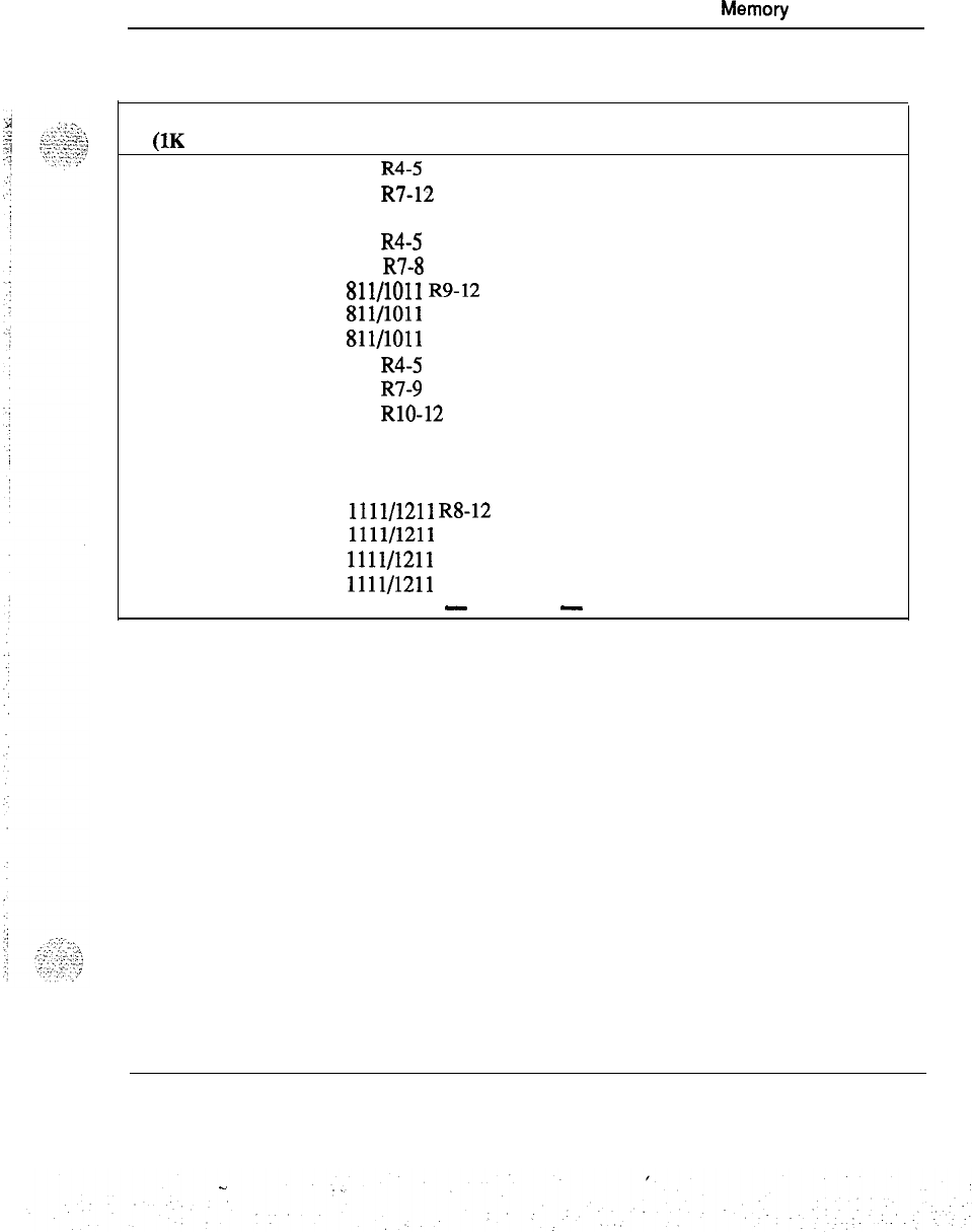
Memory
calculations 25
Table 3
Software program storage requirements (continued)
Program Version
Storage in
K
S
Comments
(1K = 1024 words)
MSB 711 R4-5 0.08
711
R7-12
0.10‘
711 R13 0.13
811 R4-5 0.08
811 R7-8 0.10
811/1011
R9-12 0.10
811/1011 R13 0.13
811/1011
R14
0.19
911 R4-5 0.08
911 R7-9 0.09
911 RlO-12 0.10
911 R13 0.13
911 R14 0.19
.
1011 R15 0.21
1111/1211
R8-12 0.07
1111/1211 R13 0.09
1111/1211 R14 0.13
1111/1211 R15 0.15
-
continued
-
---
Memory calculations 553-2201-151 Appendix 1
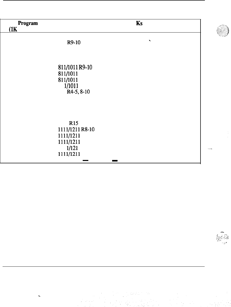
26 Memory calculations
Table 3
Software program storage requirements (continued)
progr~
Version Storage in KS Comments
(1K = 1024 words)
ss25
711 R8 0.61
711 R9-10 0.62
-
711 R12 0.64
711 R13 0.67
811 R8 0.61
811/1011
R9-10 0.62
811/1011 R12 0.64
811/1011 R13 0.67
81 l/1011 R14 0.72
911
R4-5,8-10
0.61
911 R7 0.60
911 R12 0.63
911 R13 0.66
911 R14 0.71
1011 R15 0.96
1111/1211
RS-10 0.49
1111/1211 R12 0.50
1111/1211 R13 0.49
111 l/121 1 R14 0.53
1111/1211 R15 0.71
-
continued
-
-
r
;
::.:-
:.I’-::.:
:
.::.
4
._
.,.
._’
Memory calculations 553-2201-151 Appendix 1
.
.

Memory calculations 27
Table 3
Software program storage requirements (continued)
Program Version Storage in K
S
Comments
(1K
=
1024 words)
DDSP 711 R4 1.81
711 R5 1.82
-
711 R7 2.10
711 R8 2.11
711 R9 2.47
711
RlO
2.98
711 R12-13 3.37
811 R4 1.81
811 RS 1.82
811 R7 2.10
811 R8 2.11
811/1011
R9
2.47
811/1011
RlO 2.98
.
811/1011
R12
3.36
811/1011 R13 3.67
811/1011
R14
3.98
911 R4 1.79
911 R5 1.79
911 R7 2.07
911 R8 2.08
911 R9 2.43
911 RlO 2.93
911 R12 3.32
911 R13 3.63
911 R14 3.94
1011 R15 4.63
1111/1211 R8 1.60
1111/1211 R9 1.87
1111/1211
RlO 2.27
1111/1211 R12 2.58
111 l/121 1 R13 2.66
1111/1211 R14 2.88
1111/1211 R15 3.35
-
continued
-
Memory calculations 553-2201-151 Appendix 1
Y

28 Memory
calculations
Table 3
Software program storage requirements (continued)
Program Version Storage in K
S
Comments
UK
= 1024 words)
ODAS
711,811/1011,911
1.12
711,811/1011,911
R9
_
1.22
711,811/1011,911
1.21
RlO-12
711,811/1011
R13 1.22
811/1011 R14 1.22
911 R13-14 1.20
1011 R15 0.72
1111/1211 R8 0.88
1111/1211 R9 0.96
1111/1211
RlO-12 0.94
1111/1211
R13-15 0.88
-
continued
-
Memory calculations
553-2201-151 Appendix 1
s.
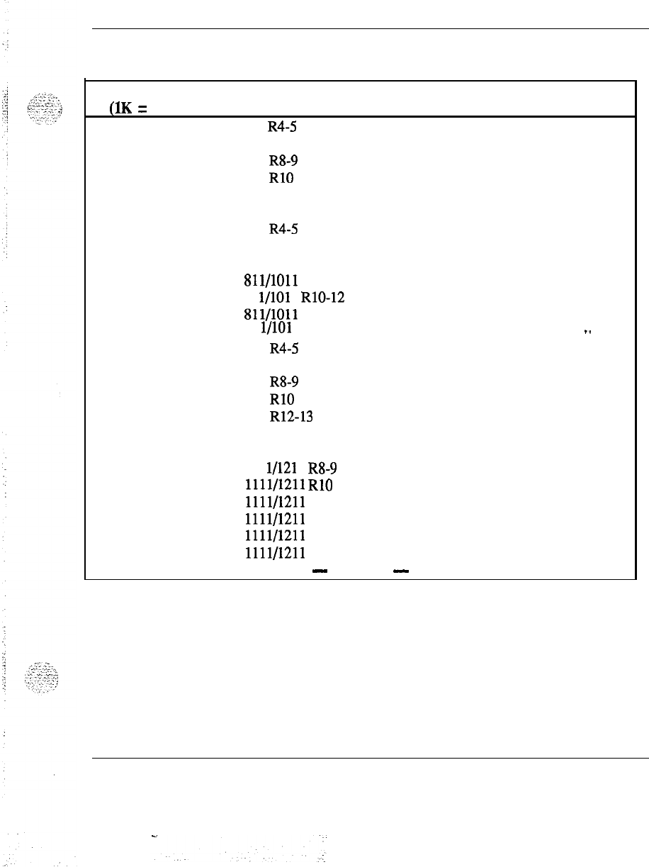
Memory calculations 29
Table 3
Software program storage requirements (continued)
Program
Version Storage in K
S
Comments
(1K = 1024 words)
DI 711 R4-5 0.58
711 R7 0.61‘
711 R8-9 0.63
711 RlO 0.65
711 R12 0.68
711 R13 0.67
811 R4-5 0.58
811 R7 0.61
811 R8 0.63
Sll/lOll
R9
0.63
81
l/101
1 RlO-12 0.65
811/1011 R13 0.67
81 l/101 1 R14 0.70
_.
911 R4-5 0.57
911 R7 0.59
911 R8-9 0.62
911 RlO 0.62
911 R12-13 0.67
911 R14 0.69
---
1011 R15 0.74
111 l/121 1 R8-9 0.46
1111/1211
RlO 0.47
1111/1211
R12
0.50
1111/1211 R13 0.49
1111/1211 R14 0.50
1111/1211 R15 0.54
-
continued
-
Memory calculations 553-2201-l 51 Appendix 1
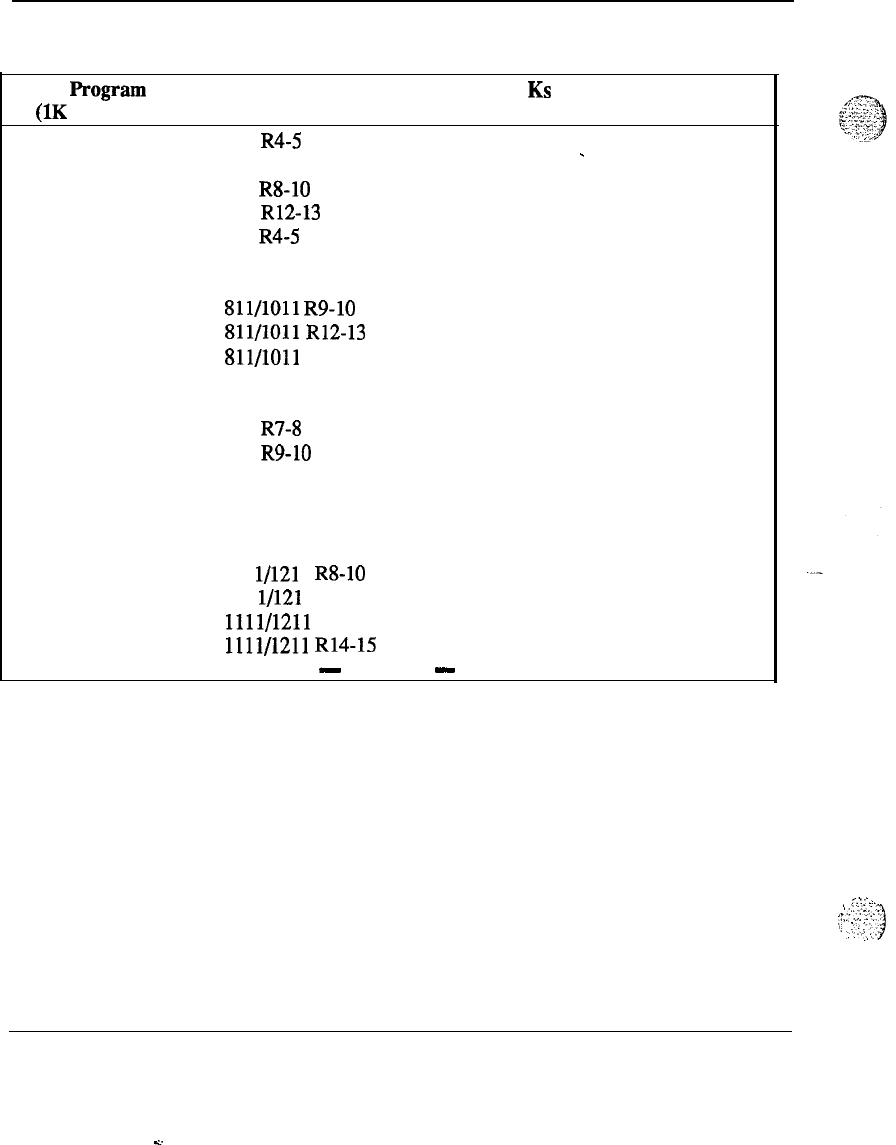
30 Memory calculations
Table 3
Software program storage requirements (continued)
hOgGUll
Version Storage in KS Comments
(1K = 1024 words)
DISA 711 R4-5 0.28
-
711 R7 0.29
711 R8-10 0.30
711 R12-13 0.32
811 R4-5 0.28
811 R7 0.29
811 R8 0.30
811/1011
R9-10 0.30
811/1011
R12-13 0.32
Sll/lOll
R14 0.34
911 R4 0.27
911 R5 0.28
911 R7-8 0.29
911 R9-10 0.30
911 R12 0.34
911 R13 0.32
911 R14 0.34
1011 R15 0.35
111 l/121 1 R8-10 0.22
111 l/121 1 R12 0.26
1111/1211 R13 0.23
1111/1211
R14-15 0.25
-
continued
-
Memory calculations 553-2201-151 Appendix 1
c.:-:;,
.
.
.
‘.,..
.1’..
:.
1:
:::..7:.1
.,
.c.
.A’,:
.
:.
-..
.’
.:.:
:
i-
.,>:
;.,
:
1,
[
:
,:.
:.;
j
Table 3
Software program storage requirements (continued)
Memory
calculations
31
Program Version Storage in K
S
Comments
(1K = 1024 words)
CHG 711 R4-5 0.24
711 R7
.
0.29
711 R8 0.34
711
R9-12
0.35
711 R13 0.37
811 R4-5 0.24
811 R7 0.29
811 R8 0.34
811/1011
R9-12 0.35
811/1011
R13 0.37
811/1011
R14-15 0.38
911 R4-5 0.24
911 R7 0.28
.
911 R8 0.33
911 R9-12 0.34
911 R13 0.37
911 R14 0.38
111 l/121 1 R8-10 0.25
1111/1211 R12 0.26
._
1111/1211 R13 0.27
1111/1211
R14-15 0.28
-
continued
-
Memory calculations
553-2201-151
Appendix 1
c.
:
.‘...
32 Memory calculations
Table 3
Software program storage requirements (continued)
Program Version Storage in KSComments
(1K = 1024 words)
CAB 711 R4
1.11
-
711 R5-9 1.12
711 RlO-12 1.14
711 R13 1.24
811 R4
1.11
811 R5-8 1.12
811/1011
R9 1.12
81
l/101
1
RlO-12 1.14
811/1011
R13
1.24
811/1011
R14
1.26
911 R4 1.10
911 R5-7
1.11
911 R8-9 1.12
911 RlO-12 1.13
911 R13 1.23
911 R14 1.25
lOllR15
1.28
111 l/121 1 R8-9 0.84
1111/1211
RlO-12 0.85
1111/1211
R13
0.88
1111/1211
R14
0.90
1111/1211
R15
0.91
3AUT 711 R4-12 0.30
711 R13 0.31
811 R4-8 0.30
811 R9 0.30
81 l/101 1 RlO-12 0.30
811/1011
R13-15 0.31
911 R4-12 0.29
911 R13 0.30
911 R14 0.31
1111/1211
R8-12 0.22
1111/1211
R13-15 0.21
-
continued
-
Memory calculations 553-2201-151 Appendix 1
L.
.-
-.
Table 3
Software program storage requirements (continued)
Memory calculations 33
prOgMtl
Version Storage in K
S
Comments
(1K = 1024 words)
CASM 711 R4-5 0.14
711
R7-10
-
0.15
711 R12 0.16
711 R13 0.19
811 R4-5 0.14
811 R7-8 0.15
Sll/lOll
R9-10 0.15
811/1011
R12- 0.17
Sll/lOll
R13 0.19
Sll/lOll
R14 0.22
911 R4-5 0.13
911 R7-10 0.15
911 R12 0.17
911 R13 0.19
911 R14 0.22
1011 R15 0.23
111 l/121 1 R8-10 0.11
1111/1211
R12
0.13
1111/1211 R13 0.14
---
1111/1211 R14 0.16
1111/1211 R15 0.17
-
continued
-
Memory calculations 553-2201-151 Appendix 1
34 Memory calculations
Table 3
Software program storage requirements (continued)
Program Version Storage in K
S
Comments
(1K = 1024 words)
2ASR 711 R4 6.05
711 R5 6.08
-
711 R7 6.53
711 R8 6.54
711 R9 6.60
711 RlO 6.64
711 R12 6.81
711 R13 6.92
811 R4 6.06
811 R5 6.12
811 R7 6.57
811 R8 6.59
Sll/lOll
R9 6.65
811/1011
RlO 6.69
81 l/101 1 R12 6.86
811/1011
R13
6.97
81 l/101 1 R14 7.49
911 R4 5.97
911 R5 6.02
911 R7 6.52
911
R8 6.53
911
R9 6.60
911
RlO 6.64
911 R12 6.80
911 R13 6.92
911 R14 7.44
1011 R15 7.85
1111/1211
R8
5.14
1111/1211
R9 5.19
1111/1211
RlO 5.22
1111/1211
R12
5.34
1111/1211
R13
4.95
111 l/121 1 R14 5.33
1111/1211
R15
5.56
-
continued
-
Memory calculations 553-2201-151 Appendix 1
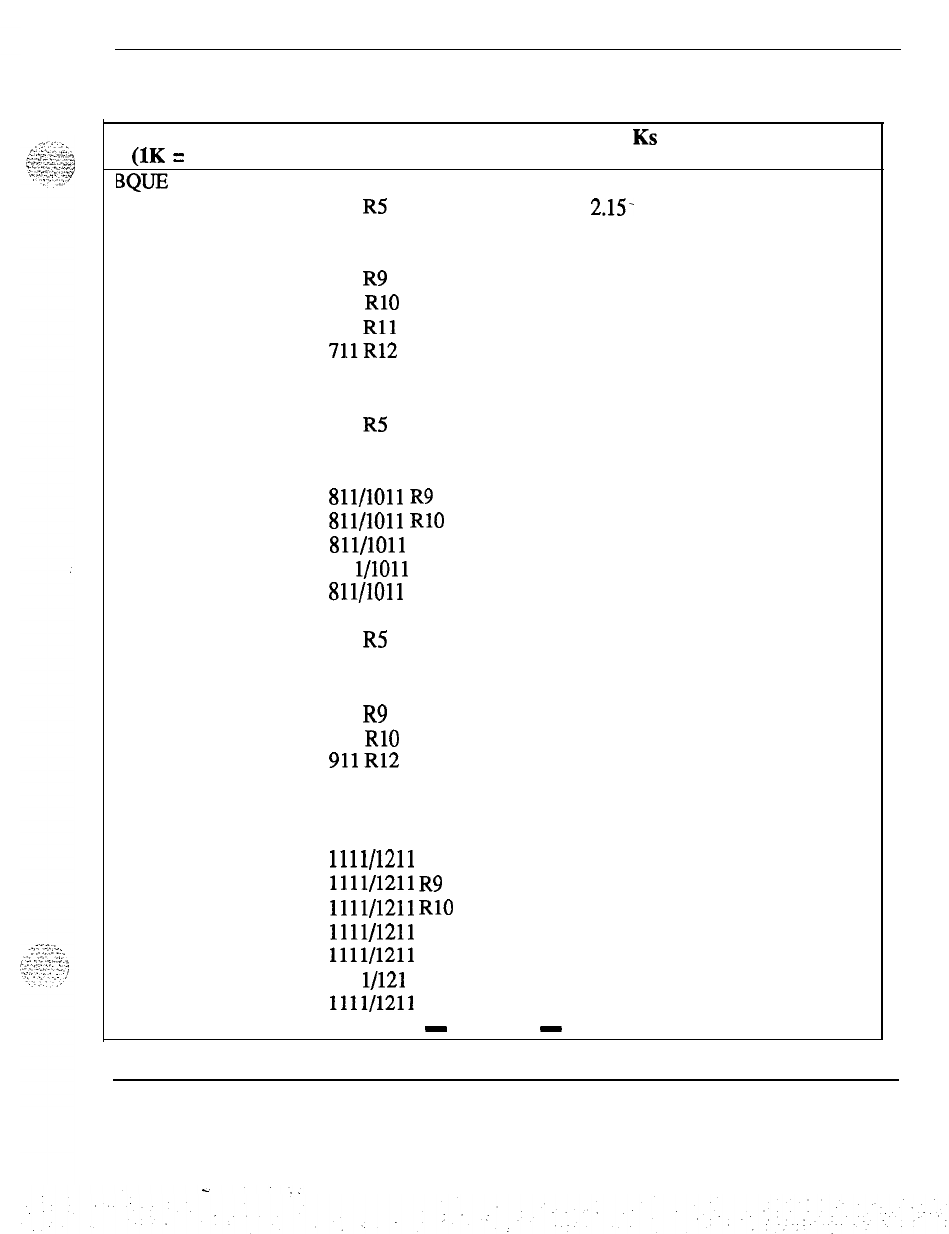
Memory calculations 35
Table 3
Software program storage requirements (continued)
Program
(1K = 1024 words)
BQE
Version Storage in KS
711 R4 2.05
Comments
711 R5 2.15.
711 R7 2.27
711 R8 2.29
711 R9 2.33
711 RlO 2.42
711
Rll
2.46
711R12
2.47
711 R13 2.55
811 R4 2.06
811 R5 2.16
811 R7 2.27
811 R8 2.29
.
811/1011
R9 2.33
811/1011
RlO 2.43
811/1011
R12
2.56
81 l/1011 R13 2.47
811/1011
R14
2.52
911 R4 2.03
911 R5 2.12
911 R7 2.24
911 R8 2.25
911 R9 2.29
911 RlO 2.39
911R12
2.53
911 R13 2.43
911 R14 2.59
1011 R15 2.70
1111/1211 R8 1.76
1111/1211
R9 1.79
1111/1211
RlO 1.86
1111/1211
R12
1.89
1111/1211 R13 1.83
111 l/121 1 R14 1.87
1111/1211 R15 1.93
-
continued
-
Memory calculations 553-2201-l 51 Appendix 1
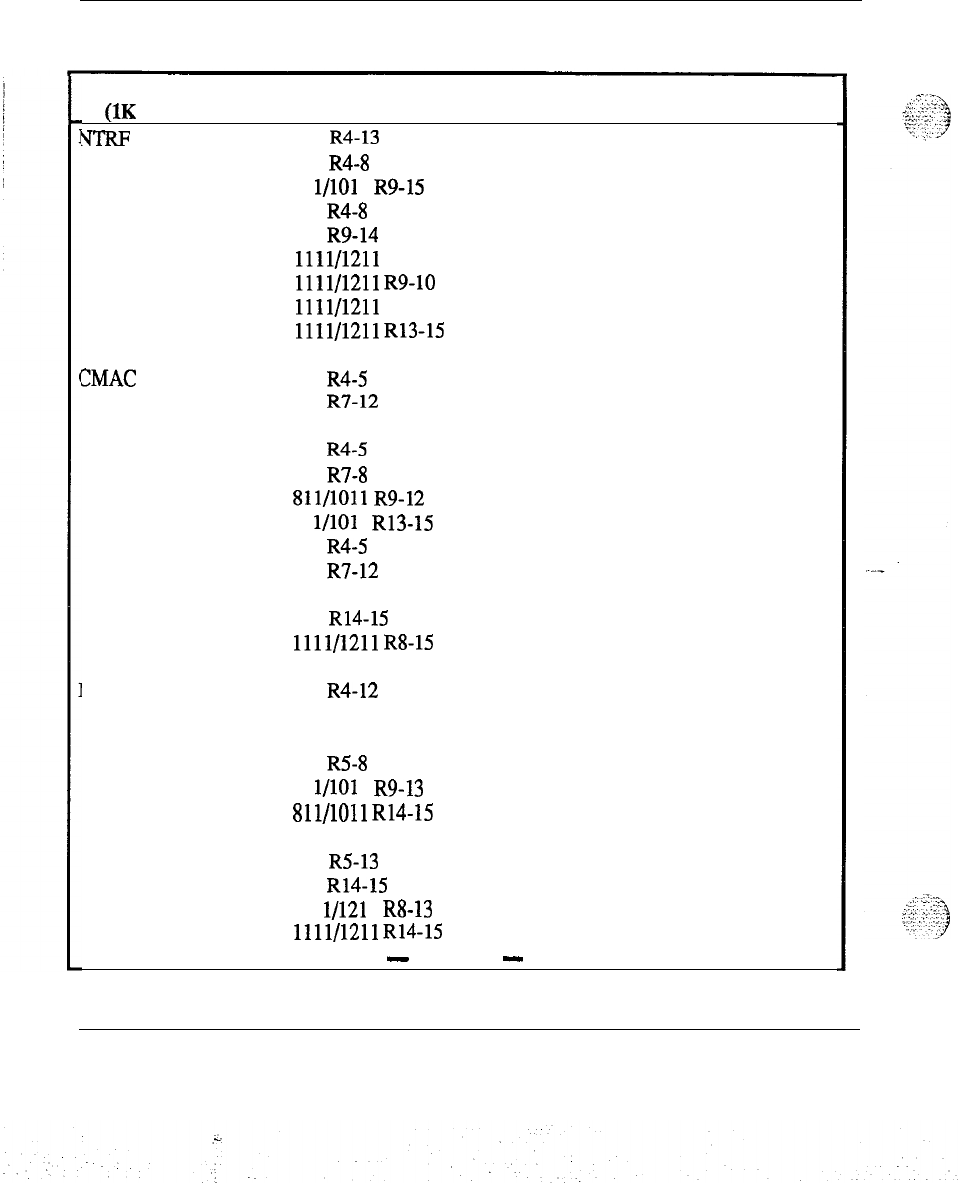
36 Memory calculations
Table 3
Software program storage requirements (continued)
Program Version Storage in K
S
Comments
(1K = 1024 words)
VTRF
711 R4-13
811 R4-8
81 l/101 1 R9-15
911 R4-8
911 R9-14
1111/1211 R8
1111/1211
R9-10
1111/1211 R12
1111/1211
R13-15
ZMAC 711 R4-5
711 R7-12
711 R13
811 R4-5
811 R7-8
811/1011
R9-12
81 l/101 1 R13-15
911 R4-5
911 R7-12
911 R13
911 R14-15
1111/1211
R8-15
MCDR 711 R4-12
711 R13
811 R4
811 R5-8
81 l/101 1 R9-13
811/1011
R14-15
911 R4
911 R5-13
911 R14-15
111 l/121 1 R8-13
1111/1211
R14-15
0.54
0.54
0.54
0.52
0.53
0.44
0.45
0.45
0.38
0.82
0.83
1.00
0.82
0.83
0.83
1.00
0.81
0.83
0.97
1.00
0.70
1.20
1.31
1.20
1.31
1.19
1.29
0.91
Note 5
Note 5
Note 5
Note 5
-
continued
-
Memory calculations 553-2201-151 Appendix 1
Memory calculations 37
Table
3
Software program storage requirements (continued)
Program
Version Storage in K
S
Comments
(1K = 1024 words)
NCOS
711,811,911,1011
0.10
711,811,911,1011
R13 0.08‘
811,911,1011
R14-15 0.08
1011 R15 0.08
1111/1211
R8-12 0.08
1111/1211
R13-15 0.06
-
continued
-
Memory calculations 553-2201-151 Appendix 1
Y
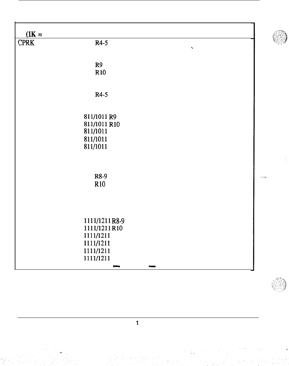
38 Memory calculations
Table 3
Software program storage requirements (continued)
Program Version Storage in K
S
Comments
(1K = 1024 words)
ZPRK
711
R4-5 3.41
711 R7 3.51
-
711 R8 3.53
711 R9 3.54
711 RlO 3.58
711 R12 3.76
711 R13 3.98
811 R4-5 3.41
811 R7 3.51
811 R8 3.53
811/1011
R9 3.53
Sll/lOll
RlO 3.58
811/1011
R12
3.76
.
811/1011
R13
3.98
811/1011
R14
4.12
911 R4 3.35
911 R5 3.36
911 R7 3.45
911 R8-9 3.47
911 RlO 3.52
911 R12 3.70
911 R13 3.95
911 R14 4.09
1011 R15 4.23
1111/1211
R8-9 2.60
1111/1211
RlO 2.62
1111/1211 R12 2.76
1111/1211 R13 2.80
1111/1211 R14
2.90
1111/1211 R15 2.97
-
continued
-
Memory calculations 553-2201-151 Appendix
1
Table 3
Software program storage requirements (continued)
Memory
calculations 39
Program Version Storage in K
S
Comments
(1K = 1024 words)
ssc
711,811,911,1011
0.10
811,911,1011
R14-15 0.10‘
1111/1211
R8-15 0.08
IMS (UST, UMG) 711 R4 7.47
711 RS 7.49
711 R7 7.59
711 R8 7.63
711 R9 7.70
711 RlO 2.80
711 R12 2.83
711 R13 3.00
811 R4 7.47
811 R5 7.49
.
811 R7 7.59
811 R8 7.63
811/1011
R9 7.70
811/1011
RlO 2.80
811/1011
R12
2.83
811/1011 R13 3.00
Sll/lOll
R14-15 3.02
911 R4 7.36
911 R5 7.38
911 R7 7.47
911 R8 7.51
911 R9 7.58
911 RlO 2.75
911 R12 2.79
911 R13 2.97
911 R14 2.98
1111/1211 R8 5.97
1111/1211
R9 6.03
1111/1211
RlO 2.12
1111/1211
R12
2.14
1111/1211 R13 2.16
1111/1211
R14-15 2.17
-
continued
-
Memory calculations 553-2201-151 Appendix 1
40 Memory calculations
”
Table 3
Software program storage requirements (continued)
Program Version Storage in Ks Comments
(1K = 1024 words)
ROA
711 0.36
711 RlO 0.36
.
711 R12 0.38
711 R13 0.40
811/1011 0.38
811/1011
RlO 0.38
811/1011 R12 0.38
811/1011 R13 0.40
811/1011 R14 0.42
911 R4-7 0.36
911 R8 0.10
911 RlO 0.27
911 R12 0.10
911 R13-14 0.11
1011 R15 0.43
1111/1211
R8-9 0.08
1111/1211
RlO-14 0.08
1111/1211 R15 0.31
-
continued
-
Memory calculations 553-2201-151 Appendix 1
..:
:,
.‘..-‘.L.-
.
.,
_
3
.‘.‘-“‘:
*
,:
:
J
:
:.’
Memory calculations 41
Table 3
Software program storage requirements (continued)’
I
prOgMIU
Version
Storage in KS
Comments
(lK
= 1024 words)
WG
711 R4 2.03
711
R5-7 2.30
711 RS-10 2.32
711 R12-13 2.63
811 R4 2.03
811
R5-7
2.30
811 R8 2.32
811/1011
R9-10 2.32
811/1011
R12-13 2.63
Sll/lOll
R14
2.68
911 R4 1.99
911
R5-7 2.26
911
R8-10
2.27
6
.
911 R12 2.65
911 R13 2.59
911 R14 2.64
1011 R15 2.69
111 l/121 1 R8-10 1.83
1111/1211
R12
2.09 .--
1111/1211
R13
1.97
1111/1211
R14-15 2.01
-
continued
-
Memory calculations 553-2201-l 51 Appendix 1
%.
:
42 Memory calculations
Table 3
Software program storage requirements (continued)
1
L
Program Version Storage in K
S
Comments
(1K = 1024 words)
MCBQ 711 R4 2.53
711 R5 2.56
711 R7 2.66
711 R8 2.67
711 RlO-12 2.68
711 R13 2.76
811 R4 2.54
811 R5 2.57
811 R7 2.68
811 R8 2.67
811/1011
R9 2.69
81 l/101 1 RlO-12 2.70
811/1011 R13 2.78
811/1011 R14 2.81
911 R4 2.50
911 R5 2.52
911 R7-8 2.63
911 R9 2.64
911 RlO-12 2.65
911 R13 2.74
911 R14 2.78
1011 R15 2.86
1111/1211
R8 2.07
1111/1211
R9 2.08
1111/1211
RlO-12 2.09
1111/1211 R13 1.95
1111/1211 R14 1.98
111/1211 R15 2.01
NSC
711,811,911,1011,
1111,121l
0
All Releases
-
continued
-
Memory calculations 553-2201-l 51 Appendix 1
2.
:
-.
Memory
calculations 43
Table 3
Software program storage requirements (continued)
!
I
:y_:.-
..,.
:-,<:
i.,;--;:.:.
;
1
Program Version Storage in K
S
Comments
(1K = 1024 words)
BACD 711 R4 8.98
711 R5 9.01‘
711 R7 10.68
711 R8 10.91
711 R9 11.64
711 RlO 12.79
711 R12 15.02
711R13
15.66
811 R4 8.99
811 R5 9.01
811 R7 10.86
811 R8 10.92
81 l/101 1 R9 11.67
811/1011
RlO 12.83
81 l/1011 R12 15.05
811/1011 R13 15.69
811 R14 16.13
911 R4 8.85
911 R5 8.87
---
911 R7 10.69
911 R8 10.75
911 R9 11.84
911 RlO 12.97
911 R12 15.17
911 Ri3
15.90
911 R14 16.35
1011 R15 17.63
1111/1211 R8 8.50
1111/1211 R9 9.35
1111/1211
RlO 10.24
1111/1211
R12
11.97
1111/1211 R13 11.36
111 l/121 1 R14 11.68
1111/1211 R15 12.78
-
continued
-
Memory calculations 553-2201-l 51 Appendix 1
.
.
. .
::
44 Memory
calculations
Table 3
Software program storage requirements (continued)
Program Version Storage in K
S
Comments
(1K = 1024 words)
ACDB 711 0.05
711 R12 0.09
-
711 R13 0.12
811 R4-7 0.05
811 R8 0.04
81
l/101 1 R9-10
0.05
81 l/101 1 R12 0.09
811/1011
R13-14 0.12
911 0.05
911 R12 0.09
911 R13-14 0.12
1011 R15 0.13
111 l/121 1 R8-10 0.04
111
l/121
1 R12 0.09
1111/1211
R13-14 0.08
1111/1211 R15 0.09
-
continued
-
Memory calculations 553-2201-151 Appendix 1
.
.
,
Memory calculations 45
Table 3
Software program storage requirements (continued)
r
PrOgKUU
(1K
=
1024 words)
ACDC
Version Storage in K
S
711 R4 13.54
711 R5 13.49
.
711 R7 14.16
711 R8 14.19
711 R9 14.75
711 RlO 15.77
711 R12 16.97
711R13
17.99
811 R4 13.54
811 R5 13.49
811 R7 14.16
811 R8 14.19
811/1011
R9 14.75
811/1011
RlO 15.77
811/1011
R12
16.97
811/1011 R13 17.99
81 l/101 1 R14 17.98
911 R4 13.39
911 R5 13.34
911 R7 14.01
911 R8 14.04
911 R9 14.60
911 RlO 15.61
911 R12 16.62
911 R13-14 17.83
1011 R15 20.87
1111/1211 R8 11.25
1111/1211
R9 11.67
111 l/121 1 RlO 12.46
1111/1211
R12
13.26
1111/1211
R13-14 12.77
1111/1211 R15 14.80
Comments
. .
.-,
LMAN
711,811,911,1011,
0All Releases
1111,121l
-
continued
-
Memory calculations 553-2201-l 51 Appendix 1
46 Memory
calculations
Table 3
Software program storage requirements (continued)
Program Version Storage in K
S
Comments
(1K
=
1024 words)
MUS 711
R4-5 1.03
.
711 R7-9 1.04
711 RlO 1.05
711 R12 1.28
711 R13 1.29
811 R4 1.03
811 R5-7 1.04
811/1011
R8-10 1.05
Sll/lOll
R12
1.06
Sll/lOll
R13-14 1.29
911 R4-5 1.28
911 R7-9
1.01
911 RlO 1.02
911 R12 1.03
911 R13 1.26
911 R14 1.27
1011 R15 1.39
1111/1211
R8-9 1.25
1111/1211
RlO 0.81
1111/1211 R12 0.99
1111/1211
R13-14 0.91
1111/1211 R15
0.97
ACDA
711,811,911,1011,
0All Releases
1111,121l
-
continued
-
Memory calculations
553-2201-151
Appendix 1
-._
.I.:
.:I
::.
,.-I..
::
>
:.,.:
-,I
i
.,
.L’
.
.
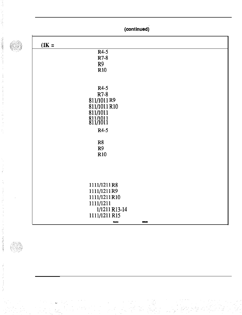
Memory calculations 47
Table3
Software program storage requirements
(continuedj
Program Version Storage in K
S
Comments
(1K
=
1024 words)
MWC
711 R4-5
1.19
711 R7-8 1.24
711 R9
1.26
711
RlO
1.29
711 R12 1.38
711 R13 1.42
811 R4-5 1.19
811 R7-8 1.24
811/1011
R9
1.26
811/1011
RlO
1.29
811/1011
R12 1.38
811/1011
R13 1.42
811/1011
R14 1.43
. .
911 R4-5 1.16
911 R7 1.20
911 R8
1.21
911 R9 1.23
911 RlO 1.26
911 R12 1.35
911 R13 1.40
911 R14
1.41
1011 R15
2.80
1111/1211
R8 0.92
1111/1211
R9
0.93
1111/1211
RlO 0.96
1111/1211
R12 1.02
111
l/1211
R13-14
1.01
1111/1211R15
2.03
-
continued
-
Memory calculations 553-2201-l 51 Appendix 1
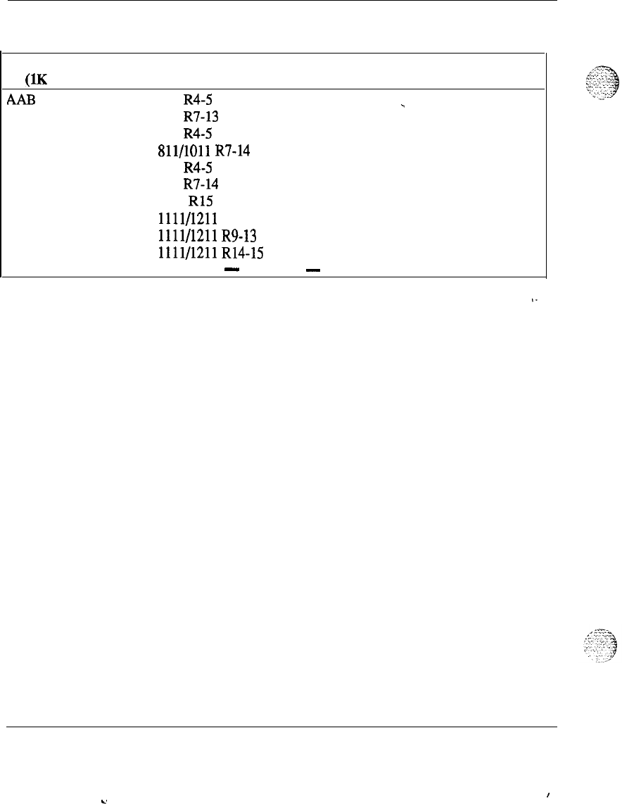
48 Memory calculations
Table 3
Software program storage requirements (continued)
Program Version Storage in K
S
Comments
(1K = 1024 words)
AAB 711 R4-5 0.07
_
711
R7-13 0.11
811 R4-5 0.07
811/1011
R7-14 0.11
911 R4-5 0.07
911
R7-14 0.11
1011 R15 0.12
1111/1211
R8
0.08
1111/1211
R9-13 0.09
1111/1211
R14-15 0.08
-
continued
-
Memory calculations 553-2201-151 Appendix 1
I
C.
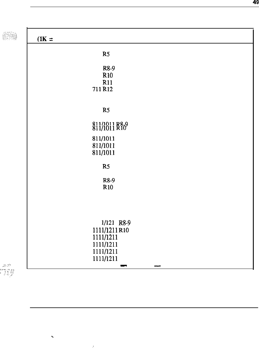
.::-
.“’
‘L’..’
“.
,,
. .
.
.
.
.
.
.
,,T,,
,.
.:.
,,
.,
Memory calculations 49
Table 3
Software program storage requirements (continued)
Program Version Storage in K
S
Comments
(1K = 1024 words)
GRP
711 R4 2.19
711 R5 2.17
711 R7 2.20
711 R8-9 2.22
711 RlO 2.26
711
Rll
2.25
711R12
2.29
711 R13 2.13
811 R4 2.18
811 RS 2.17
811 R7 2.19
811/1011
R8-9 2.21
811/1011
RlO 2.25
.
811/1011
R12
2.28
811/1011 R13 2.13
811/1011 R14 2.32
911 R4 2.15
911 R5 2.13
911 R7 2.16
911 R8-9 2.18
911 RlO 2.22
911 R12 2.24
911 R13 1.65
911 R14 2.30
1011 R15 2.35
111 l/121 1 R8-9 2.11
1111/1211
RlO 1.68
1111/1211 R12 1.70
1111/1211 R13 1.49
1111/1211 R14 1.63
1111/1211 R15 1.65
-
continued
-
Memory calculations 553-2201-l 51 Appendix 1
.
.
:
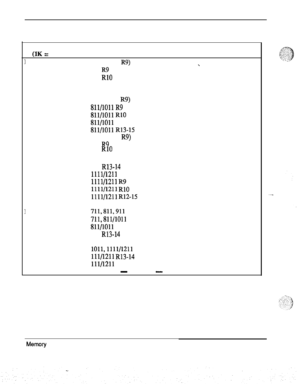
50 Memory calculations
Table 3
Software program storage requirements (continued)
Program Version Storage in Ks Comments
(1K = 1024 words)
NFCR 7 11 (before R9) 0.29
_
711 R9 0.38
711 RlO 0.44
711 R12 0.46
711 R13 0.50
8 11 (before
R9)
0.29
811/1011
R9 0.38
811/1011
RlO 0.44
811/1011
R12
0.46
811/1011
R13-15 0.50
9 11 (before R9) 0.29
911 R9 0.38
911 RlO 0.43
911 R12 0.45
911 R13-14 0.49
1111/1211
R8
0.23
1111/1211
R9 0.30
1111/1211
RlO 0.33
1111/1211
R12-15 0.35
LNK
711,811,911
0.15
711,811/1011
R13
3.46
811/1011
R14
3.46
911 R13-14 3.43
1011 R15 4.37
1011,1111/1211 0.12
111/1211
R13-14 2.45
111/1211 R15 3.08
-
continued
-
Memory calculations
553-2201-151 Appendix 1
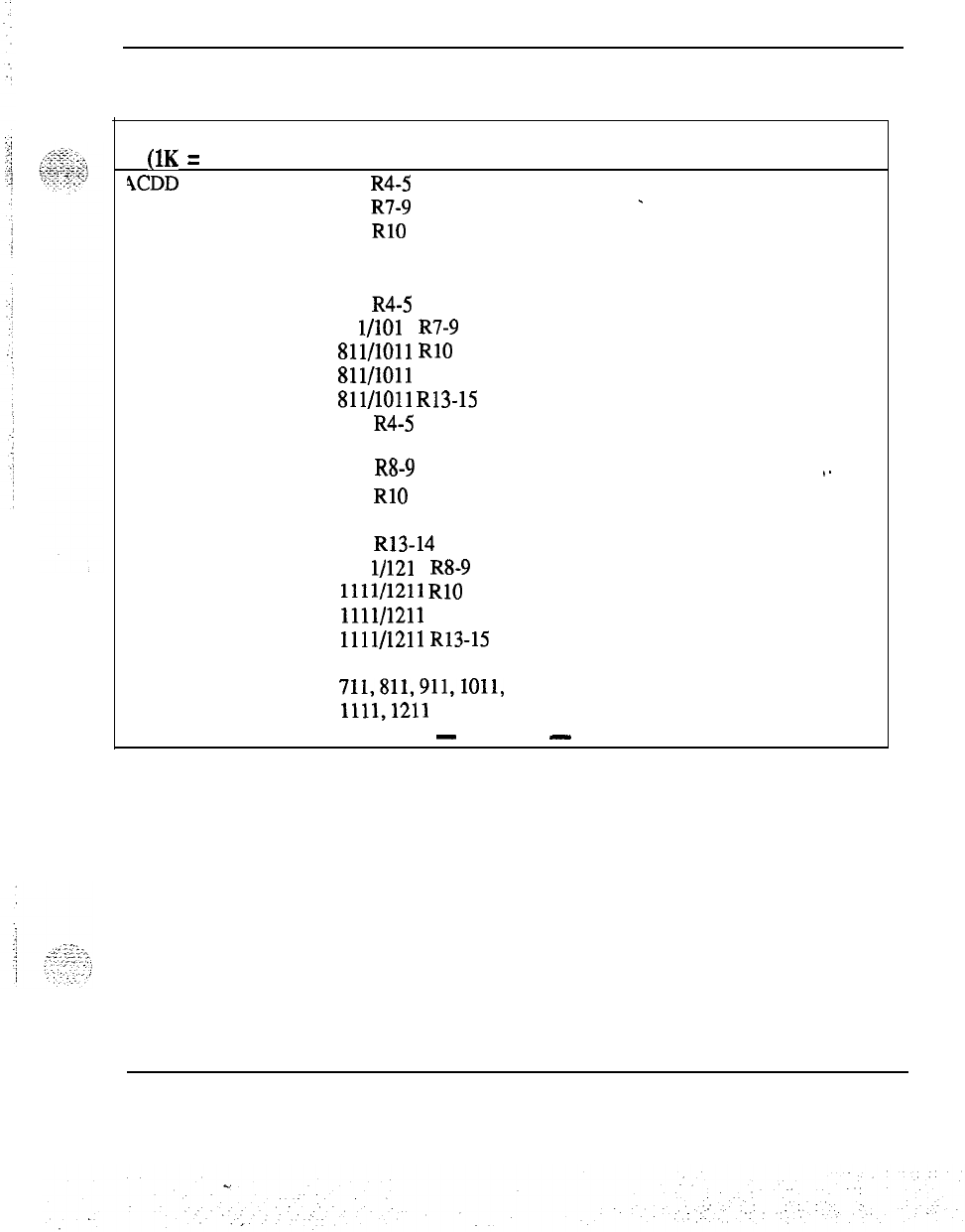
Memory calculations 51
Table 3
Software program storage requirements (continued)
Program
Version
Storage in
K
S
Comments
(1K = 1024 words)
9CDD 711 R4-5 2.22
711 R7-9 2.23
-
711 RlO 2.50
711 R12 2.83
711 R13 1.50
811 R4-5 2.22
81 l/101 1 R7-9 2.23
811/1011
RlO 2.53
811/1011
R12
2.83
Sll/lOll
R13-15 1.50
911 R4-5 2.19
911 R7 2.20
911 R8-9 2.21
.-
911 RlO 2.50
911 R12 2.80
911 R13-14 1.50
111 l/121 1 R8-9 1.85
1111/1211
RlO 2.07
1111/1211
R12
2.33
1111/1211
R13-15 1.03
FCA
711,811,911,1011,
0All Releases
1111,121l
-
continued
-
Memory calculations 553-2201-151 Appendix 1
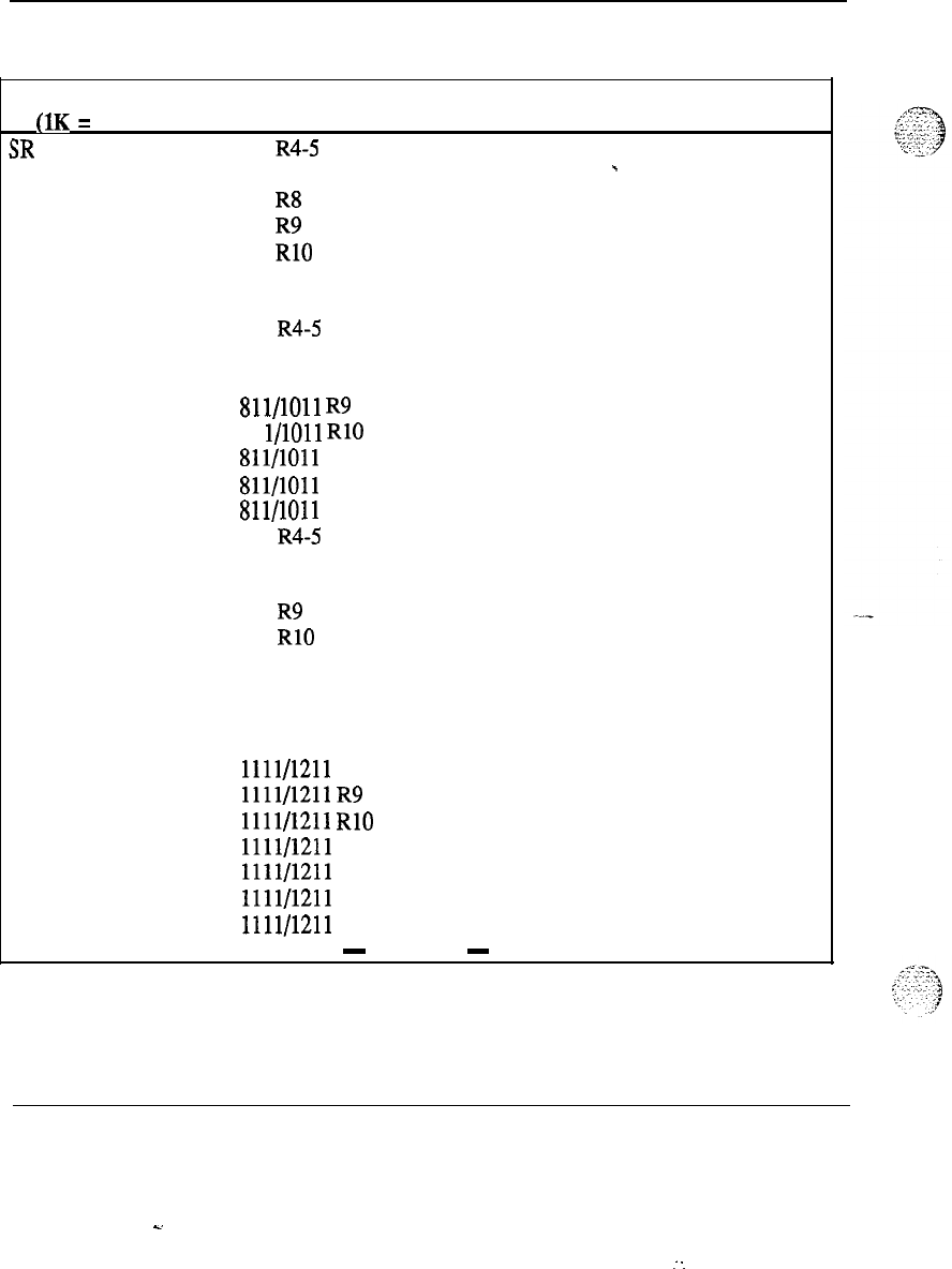
52 Memory calculations
Table 3
Software program storage requirements (continued)
!
Program Version Storage in K
S
Comments
(1K = 1024 words)
3R
711 R4-5 4.13
711 R7 4.36
-
711 R8 4.51
711 R9 4.87
711 RlO 5.48
711 R12 5.97
711 R13 6.19
811 R4-5 4.13
811 R7 4.36
811 R8 4.51
811/1011
R9 4.87
81 l/1011 RlO 5.48
811/1011
R12
5.97
.
Sll/lOll
R13
6.19
811/1011
R14
6.50
911 R4-5 4.06
911 R7 4.29
911 R8 4.44
911 R9 4.80
911 RlO 5.41
911 R12 5.89
911 R13 6.13
911 R14 6.44
1011 R15 6.56
1111/1211
R8
3.52
1111/1211
R9 3.73
1111/1211
RlO 4.20
1111/1211 R12 4.56
1111/1211 R13 4.35
1111/1211 R14 4.57
1111/1211 R15 4.61
-
continued
-
Memory calculations 553-2201-151 Appendix 1
s.
-
-.
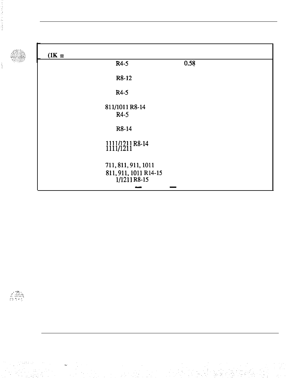
Memory calculations 53
Table 3
Software program storage requirements (continued)’
_-
,.
. . .
.
‘.:
..’
.F
,::3
.:.:-
:,
:.
:: .,
.
.:,
;
Program Version Storage in K
S
Comments
(1K = 1024 words)
AA
711 R4-5 0.55
711 R7 0.59
711 R8-12 0.65
711 R13 0.64
811 R4-5 0.58
811 R7 0.59
Sll/lOll
R8-14 0.65
911 R4-5 0.57
911 R7 0.58
911 R8-14 0.64
1011 R15 1.00
1111/1211
R8-14
0.47
1111/1211
R15
0.73
.
HIST
711,811,911,1011
0.04
811,911,1011
R14-15 0.04
111 l/1211 R8-15
0.03
-
continued
-
Memory calculations 553-2201-l 51 Appendix 1
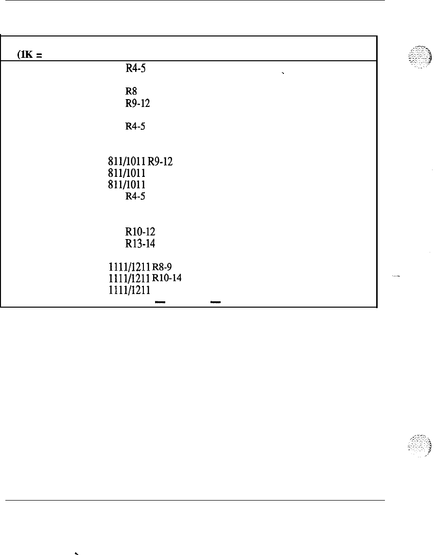
54 Memory
calculations
Table 3
Software program storage requirements (continued)
Program
Version Storage in K
S
Comments
(1K = 1024 words)
AOP 711 R4-5 0.42
_
711 R7 0.54
711 R8 0.62
711 R9-12 0.63
711 R13 0.65
811 R4-5 0.42
811 R7 0.54
811 R8 0.62
811/1011
R9-12 0.63
811/1011 R13
0.65
811/1011 R14 0.64
911 R4-5 0.42
911 R7 0.52
911 R8 0.60
911 RlO-12 0.61
911 R13-14 0.63
1011 R15 0.80
1111/1211
R8-9 0.44
1111/1211
RlO-14 0.45
1111/1211 R15 0.56
-
continued
-
Memory calculations 553-2201-l 51 Appendix 1
c
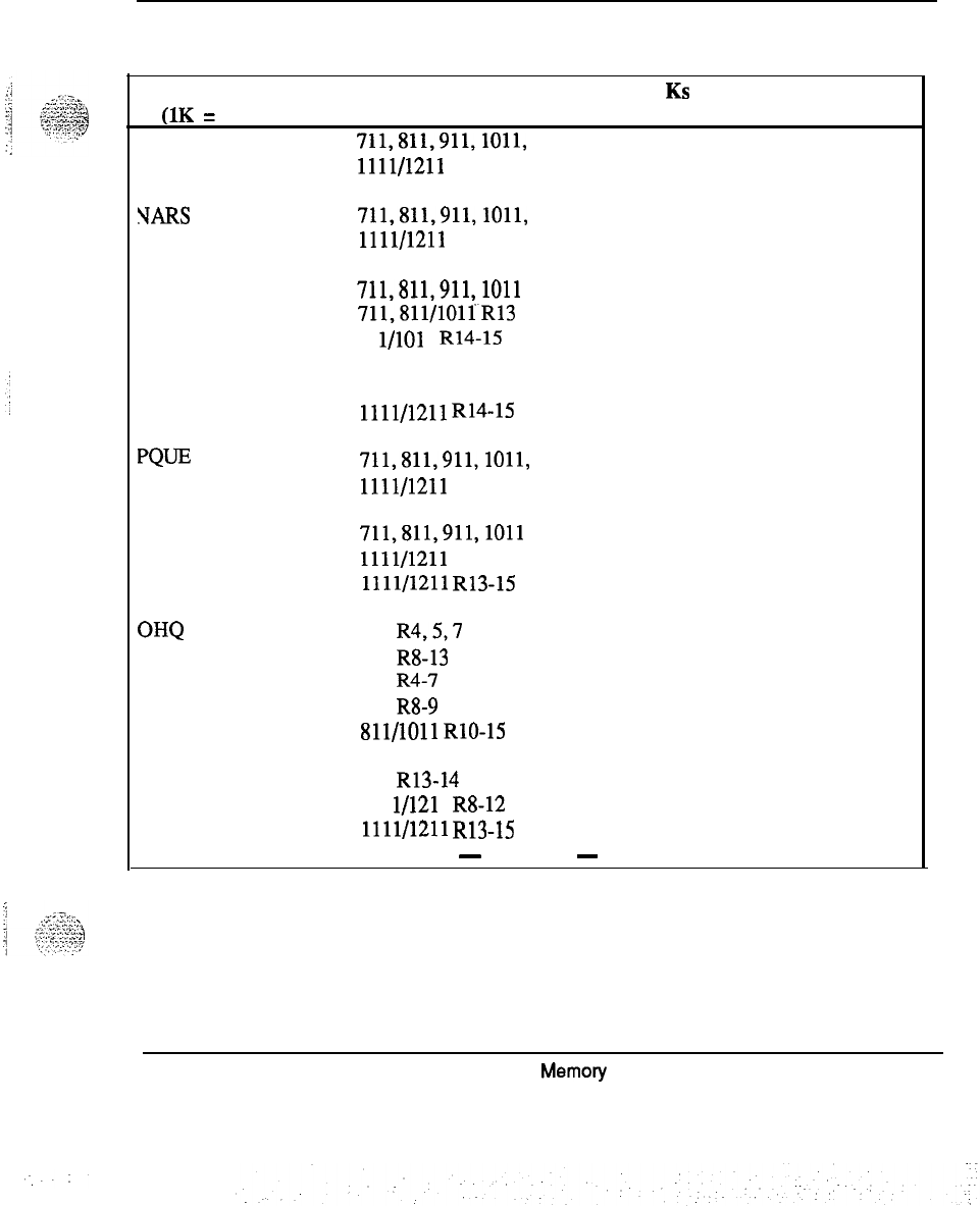
Memory calculations 55
Table 3
Software program storage requirements (continued)’
Program Version Storage in KS Comments
(1K = 1024 words)
BARS
711,811,911,1011,
0All, Releases
1111/1211
?TARS
711,811,911,1011,
1111/1211 0All Releases
CDP
PQm
711,811,911,1011
711,811/101iR13
81 l/101 1 R14-15
911 R13
911 R14
1111/1211
R14-15
711,811,911,1011,
1111/1211
0.07
0.08
0.08
0.09
0.07
0.05
0
. .
All Releases
FCBQ
711,811,911,1011
0.02
1111/1211
0.02
1111/1211
R13-15 0.01
All Releases
OHQ
711
R4,5,7
0.11
711 R8-13 0.12
811 R4-7 0.11
811 R8-9 0.12
811/1011
RlO-15 0.12
911 0.11
911 R13-14 0.12
111 l/121 1 R8-12 0.09
1111/1211
R13-15
0.08
-
continued
-
Memory
calculations 553-2201-l 51 Appendix 1
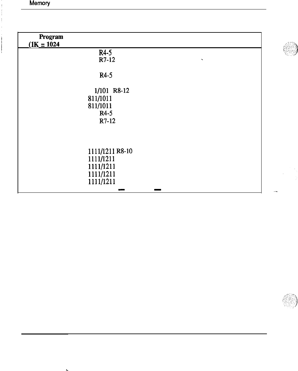
56
Memory
calculations
Table 3
Software program storage requirements (continued)
PrOgWIl
Version Storage in K
S
Comments
(1K = 1624 words)
NAUT 711 R4-5 0.49
711 R7-12 0.50
-
711 R13 0.51
811 R4-5 0.49
811 R7 0.50
81 l/101 1 RS-12 0.50
811/1011
R13
0.51
811/1011
R14
0.55
911 R4-5 0.48
911 R7-12 0.49
911 R13 0.50
911 R14 0.54
1011 R15 0.57
1111/1211
R8-10 0.38
1111/1211
R12
0.37
1111/1211 R13 0.36
1111/1211
R14
0.40
1111/1211
R15
0.41
-
continued
-
Memory calculations 553-2201-151 Appendix 1
.
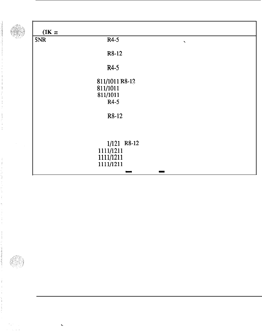
Memory calculations 57
Table 3
Software program storage requirements (continued)
Program Version Storage in K
S
Comments
(1K = 1024 words)
SNR
711
R4-5 0.76
_
711 R7 0.78
711
R8-12
0.84
711 R13 0.85
811 R4-5 0.76
811 R7 0.78
811/1011
R8-l?, 0.84
811/1011
R13
0.85
811/1011
R14
0.93
911 R4-5 0.75
911 R7 0.77
911
R8-12
0.83
911 R13 0.85
. .
911 R14 0.92
1011 R15 0.96
111
l/121
1 R8-12 0.59
1111/1211
R13 0.60
1111/1211
R14 0.65
1111/1211
R15 0.68
---
-
continued
-
Memory calculations 553-2201-151 Appendix 1
.
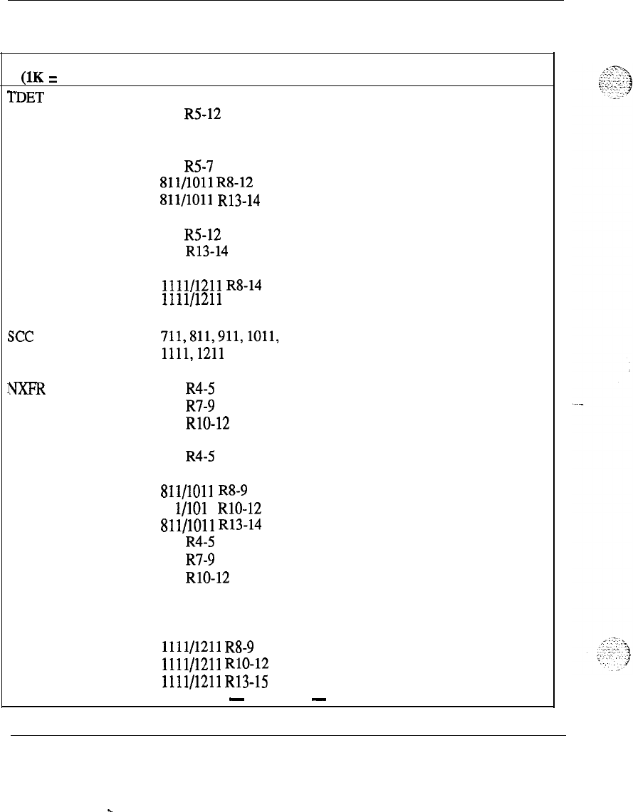
58 Memory calculations
Table 3
Software program storage requirements (continued)
Program
(1K = 1024 words)
I’DET
Version
711 R4
711 R5-12
711 R13
811 R4
811 R5-7
811/1011
R8-12
Sll/lOll
R13-14
911 R4
911 R5-12
911 R13-14
1011 R15
1111/1211
R8-14
1111/1211 R15
CommentsStorage in K
S
0.36
.
0.39
0.42
0.36
0.38
0.38
0.42
0.35
0.38
0.41
0.45
0.30
0.32
.
see
711,811,911,1011,
1111,121l
0All Releases
m
711 R4-5 0.51
711 R7-9 0.62
711 RlO-12 0.65
711 R13 0.71
811 R4-5 0.51
811 R7 0.62
811/1011
R8-9 0.62
81 l/101 1 RlO-12 0.65
Sll/lOll
R13-14 0.71
911 R4-5 0.51
911 R7-9 0.61
911 RlO-12 0.64
911 R13 0.70
911 R14 0.71
1011 R15 0.72
1111/1211
R8-9 0.51
1111/1211
RlO-12 0.53
1111/1211
R13-15 0.50
-
continued
-
Memory calculations 553-2201-151 Appendix 1
.
.
Memory calculations 59
Table3
Software program storage requirements (continued)
Program Version Storage in K
S
Comments
(1K
=
1024 words)
ATVN 711 R4 4.99
-
711 R5-7 5.00
711 R8 5.02
711 R9 5.03
711 RlO
5.12
711
R12 5.18
711 R13 5.25
811 R4 4.97
811 R5-7 4.98
811 R8 5.00
811/1011
R9 5.01
811/1011
RlO 5.10
811/1011
R12 5.17
81
l/1011
R13 5.24
811/1011
R14 5.29
911 R4 4.92
911 R5-7 4.93
911 R8-9 4.95
911 RlO 5.04
911 R12 5.11
911 R13 5.20
911 R14 5.25
1011 R15 5.52
1111/1211
R8 3.92
1111/1211
R9 3.93
111
l/121
1 RlO 4.00
1111/1211
R12 4.05
1111/1211 R13 3.80
1111/1211 R14 3.84
1111/1211 R15 3.99
ACDR
711,811,911,1011,
0All Releases
1111/1211
-
continued
-
Memory calculations 553-2201-151 Appendix 1
60 Memory calculations
Table 3
Software program storage requirements (continued)
Program Version Storage in K
S
Comments
(1K = 1024 words)
HOT 711 (before RlO) 0
.
711 RlO-12 0.24
711 R13 0.26
811/1011
(beforeR10)
0
81 l/101 1 RlO-12 0.24
811/1011 R13 0.25
811/1011
R14-15 0.26
911 (before RlO) 0
911 RlO-12 0.24
911 R13 0.25
911 R14 0.26
1111/1211
(beforeR10)
0
1111/1211
RlO 0.24
1111/1211
R12-13 0.18
1111/1211
R14-15 0.19
DHLD
711,811/1011 0.58
711,811/1011
R12
0.59
711,811/1011
R13-15 0.61
911 0.57
911 R12 0.59
911 R13-14 0.60
111 l/121 1 R8-10 0.46
1111/1211
R12
0.47
1111/1211
R13-15 0.44
LSEL
711,811/1011 0.17 All Releases
911 R4-5 0.16
911 R7-14 0.17
1111/1211
R8-15 0.12
-
continued
-
Memory calculations 553-2201-151 Appendix 1
Memory calculations 61
Table 3
Software program storage requirements (continued)
Program Version Storage in K
S
Comments
(1K = 1024 words)
ss5
711,811,911,1011,
0.01
-
All
Releases
1111/1211
DRNG
711
R4-5,7
0.41
711 R8 0.49
711 R9 0.48
711 RlO 0.68
711 R12 0.70
711 R13 0.58
811
R4-5,7
0.41
811 R8 0.49
811/1011
R9 0.48
81 l/101 1 RlO-12 0.70
.
811/1011 R13 0.60
811/1011
R14-15 0.58
911
R4-5,7
0.40
911 R8-9 0.48
911 RlO-12 0.69
911 R13-14 0.57
1111/1211 R8 0.39
1111/1211
R9 0.38
1111/1211
RlO-12 0.55
1111/1211
R13-15 0.42
-
continued
-
Memory calculations 553-2201-l 51 Appendix 1
62 Memory calculations
Table 3
Software program storage requirements (continued)
Program
(1K = 1024 words)
PBXI
Version
711 R5
711 R7
711 R8
711
R9-10
711 R12
711 R13
811 R5
811 R7
811 R8
811/1011
R9-10
811/1011
R12
811/1011
R13
811/1011
R14
911 R5
911 R7
911 RS
911 R9
911 RlO
911 R12
911 R13
911 R14
1011 R15
1111/1211
R8
1111/1211
R9
1111/1211
RlO
111 l/121 1 R12
1111/1211
R13
1111/1211
R14
1111/1211
R15
Storage in K
S
Comments
2.84
_
4.28
4.70
4.82
6.26
6.24
3.27
4.72
4.76
4.89
6.33
6.31
7.14
3.23
4.66
4.70
4.82
4.83
6.25
6.24
7.04
7.26
3.71
3.83
3.84
4.94
4.57
5.18
5.26
-
continued
-
Memory calculations 553-2201-l
51
Appendix 1
Memory calculations 63
Table 3
Software program storage requirements (continued)
Program
(1K = 1024 words)
DLDN
Version Storage in K
S
711 R5-13 0.09.
811 R5-7 0.09
Sll/lOll
R8-15 0.09
911 R5-15 0.09
1111/1211
R8-13 0.06
1111/1211
R15 0.07
Comments
4MF 711 R5 1.37
711 R7-8 1.44
711 R9 1.46
711 RlO-12 1.47
711 R13 1.57
811 R5 1.37
.
811
R7-8
1.44
811/1011
R9
1.46
811/1011
RlO-12 1.47
811/1011 R13 1.57
811/1011 R14
1.61
911 R5 1.36
---
911 R7 1.44
911 R8 1.43
911 R9 1.45
911 RlO-12 1.46
911 R13 1.57
911 R14 1.61
1011 R15 1.62
1111/1211 R8 1.09
1111/1211 R9 1.11
1111/1211
RlO-13 1.12
1111/1211 R14 1.15
1111/1211 R15 1.16
-
continued
-
Memory calculations 553-2201-l 51 Appendix 1
. .
64 Memory calculations
Table 3
Software program storage requirements (continued)
Program Version Storage in K
S
Comments
(1K = 1024 words)
CSL 711 R7 13.96
711 R8 14.68
711 R9 15.10
711 RlO 15.08
711 R12 17.04
711 R13 17.65
811 R7 13.96
811 R8 14.68
811 R9 15.10
81
l/1011
RlO 15.08
81
l/101 1
R12 17.04
81 l/1011 R13 17.64
811/1011
R14
17.65
911 R7 13.55
911 R8 14.26
911 R9 14.69
911 RlO 14.67
911 R12 16.61
911 R13-14 17.24
1011 R15 17.80
1111/1211
R8
11.23
1111/1211
R9 11.51
1111/1211
RlO 11.49
1111/1211
R12
12.99
111 l/121 1 R13-14 12.45
1111/1211
R15
12.54
IOD
711,811,911,1011,
1111/1211
0
All Releases
SC1
711
R7-13
Sll/lOll
R7-15
911 R7-14
111 l/121 1 R8-15
-
continued
-
Memory calculations 553-2201-151 Appendix 1
.
.
I
Memory calculations 65
Table 3
Software program storage requirements (continued)
Program Version Storage iu K
S
Comments
(1K = 1024 words)
JCOS
711 R7-8 0.22.
711 R9 0.24
711 RlO-13 0.25
811 R7 0.22
811 R8 0.21
811/1011
R9 0.24
81 l/101 1 RlO-14 0.25
911 R7-8 0.21
911 R9 0.23
911 RlO-12 0.24
911
Rl3-14
0.25
1111/1211 R8 0.17
1111/1211
R9 0.18
.
1111/1211
RlO-14 0.19
RESDB 811/1011 R14 4.30
911 R14 4.47
1111/1211 R14 7.46
CDRQ 711 0
811/1011 0
911 0
1111/1211 0
All Releases
ATh4 711 0All Releases
Sll/lOll
0
911 0
1111/1211 0
-
continued
-
Memory calculations 553-2201-l 51 Appendix 1
.
66 Memory calculations
Table 3
Software program storage requirements (continued)
PrOgEllU
Version Storage in K
S
Comments
(1K = 1024 words)
CSLA 711
0
.
All Releases
811/1011 0
911 0
1111/1211 0
lIENANT 711 R7 0.38
711 R8 0.43
711 R9-12 0.44
711 R13 0.43
811 R7 0.38
81 l/1011 R8 0.43
Sll/lOll
R9 0.44
Sll/lOll
RlO-12 0.44
811/1011 R13 0.43
Sll/lOll
R14
0.48
911 R7 0.38
911 R8 0.43
911 R9-12 0.44
911 R13 0.43
911 1 R14 0.47
1011 R15 0.51
1111/1211
R8
0.33
111 l/121 1 R9-12 0.34
1111/1211 R13 0.32
1111/1211
R14
0.35
1111/1211
R15
0.38
FTDS
711 0 All Releases
81 l/101 1 0
911 0
1111/1211 0
-
continued
-
Memory calculations 553-2201-151 Appendix 1
-.
Memory calculations 67
Table 3
Software program storage requirements (continued)
Program Version Storage in K
S
Comments
(1K = 1024 words)
3SET 711 R12 8.70
-
711 R13 8.75
811/1011
R12
8.69
81 l/1011 R13 8.74
Sll/lOll
R14
9.67
911 R12 8.57
911R13
8.66
911 R14 9.57
1011 R15 12.53
111 l/121 1 R12 6.66
1111/1211 R13 6.34
1111/1211 R14 6.99
. .
1111/1211 R15 9.12
BET
711 0
811/1011 0
911 0
1111/1211 0
All Releases
LNR 711 R8 0.24
711 R9 0.26
711 RlO-12 0.28
711 R13 0.30
811 R8 0.24
811/1011
R9 0.26
81 l/1011 RlO-12 0.28
811/1011
R13-15 0.30
911 R8 0.24
911 R9 0.26
911 RlO-12 0.28
911 R13-14 0.30
1111/1211 R8 0.19
1111/1211
R9 0.20
1111/1211
RlO-15 0.22
-
continued
-
Memory calculations 553-2201-151 Appendix 1
68 Memory calculations
Table 3
Software program storage requirements (continued)
Program Version Storage in K
S
Comments
(1K = 1024 words)
DLT 2 711 R9-13 0
-
811/1011
R9-14 0
911 R9-14 0
1111/1211
R9-14 0
PRETRANS 711 R8 0.33
711 R9 0.34
711 RlO-13 0.35
811 R8 0.33
811/1011
R9
0.34
81 l/1011 RlO-13 0.35
Sll/lOll
R14-15 0.37
911 R8 0.33
911 RlO-13 0.34
911 R14 0.36
1111/1211
R8
0.24
1111/1211
R9-13 0.25
1111/1211
R14-15 0.26
SUPV 711 R8 0.77
711 R9-12 0.66
711 R13 0.68
811 R8 0.78
811/1011
R9-12 0.67
81 l/1011 R13-14 0.69
911 R8 0.77
911 R9-12 0.65
911 R13 0.67
911 R14 0.68
1011 R15 0.72
1111/1211
R8 0.56
111 l/121 1 R9-14 0.48
1111/1211 R15 0.50
-
continued
-
Memory calculations 553-2201-151 Appendix 1
_.
:.
Memory calculations 69
Table 3
Software program storage requirements (continued)
Program Version Storage in K
S
Comments
(1K
=
1024 words)
Yl-DS
711 R8-13
O-
81 l/101 1 R8-14 0
911 R8-14 0
1111/1211
RS-14
0
ZPND
SLST
JPN
DNIS
711 RlO-12 0.88
711 R13
81 l/101 1 RlO-12 0.90
0.88
81 l/101 1 R13-15 0.90
911 RlO-12 0.86
911 R13-14 0.88
111 l/121 1 RlO-12 0.71
.
1111/1211
R13-15 0.64
711 0A Releases
811/1011 0
911 0
1111/1211 0
711 0All Releases
811/1011 0
911 0
1111/1211 0
711 0All Releases
811/1011 0
911 0
1111/1211 0
-
continued
-
Memory calculations 553-2201-151 Appendix 1
70 Memory calculations
Table 3
Software program storage requirements (continued)
Program Version Storage in K
S
Comments
(1K = 1024 words)
3GD 711 RlO
11.21
_
711
R12 11.51
711 R13 11.32
811/1011
RlO 11.21
Sll/lOll
R12
11.51
811/1011
R13
11.32
811/1011
R14
11.33
911 RlO 11.09
911 R12 11.35
911 R13-14 11.22
1011 R15 11.54
1111/1211
RlO 8.90
1111/1211
R12
9.13
1111/1211
R13-14 8.26
1111/1211 R15 8.40
RMS 711 RlO 1.55
711 R12 1.58
711 R13 1.60
811/1011
RlO 1.55
81 l/1011 R12 1.58
Sll/lOll
R13-14 1.60
911 RlO 1.53
911 R12 1.55
911 R13-14 1.58
1011 R15 1.67
1111/1111
RlO 1.20
1111/1111
R12
1.22
111 l/121 1 R13-14 1.18
1111/1211
R15
1.25
-
continued
-
Memory calculations 553-2201-l 51 Appendix 1
s.
..:
.:...
.:
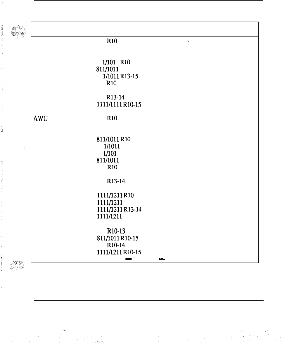
Memory calculations 71
Table 3
Software program storage requirements (continued)
Program Version Storage in Ks Comments
UK = 1024 words)
MR 711 RlO 0.85
-
711 R12 0.85
711 R13 0.89
81 l/101 1 RlO
0.85
811/1011
R12
0.85
81 l/1011 R13-15 0.89
911 RlO
0.83
911 R12
0.84
911 R13-14
0.88
1111/1111
RlO-15 0.64
Awu
711 RlO 4.49
711 R12
4.57
711 R13
4.62
811/1011
RlO
4.48
81 l/1011 R12
4.58
81 l/101 1 R13 4.61
811/1011 R14
4.62
911 RlO
4.43
911 R12 4.51
911 R13-14
4.58
1011 R15
4.34
1111/1211
RlO
3.35
1111/1211 R12
3.40
1111/1211
R13-14
3.27
1111/1211 R15
3.06
?MSI 711 RlO-13
0.05
811/1011
RlO-15
0.05
911 RlO-14
0.05
1111/1211
RlO-15 0.04
-
continued
-
Memory calculations 553-2201-l 51 Appendix 1
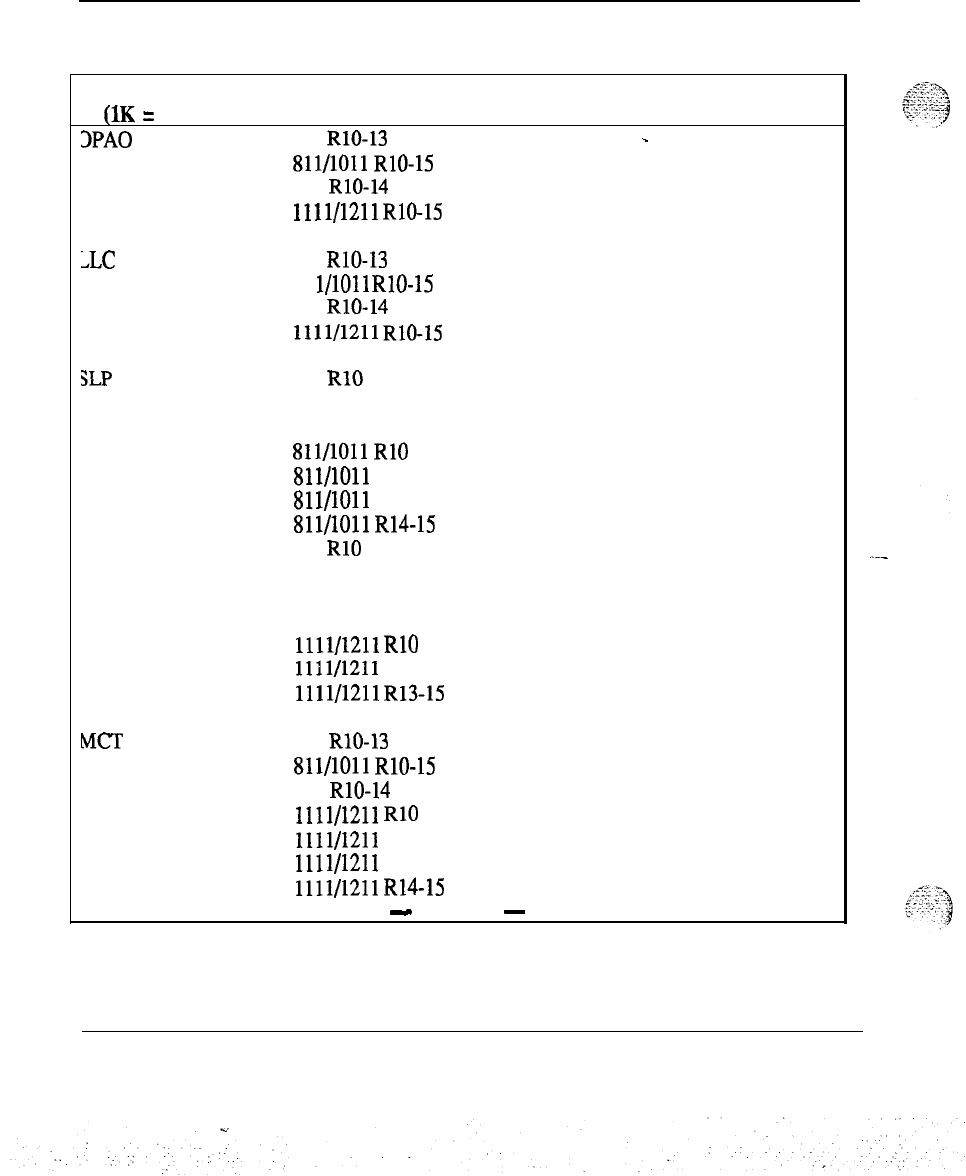
72 Memory calculations
Table 3
Software program storage requirements (continued)
Program Version Storage in K
S
Comments
(1K = 1024 words)
3PAO 711 RlO-13 0.05
-
811/1011
RlO-15 0.05
911 RlO-14 0.05
1111/1211
RlO-15 0.04
>LC 711 RlO-13 0.08
81 l/1011 RlO-15 0.08
911 RlO-14 0.08
1111/1211
RN-15
0.06
SLP
711
RlO
1.11
711 R12 1.17
711 R13 1.23
811/1011
RlO 1.10
811/1011 R12 1.17
Sll/lOll
R13 1.22
811/1011
R14-15 1.23
911 RlO 1.09
911 R12 1.16
911 R13
1.21
911 R14 1.22
1111/1211
RlO 0.87
1111/1211
R12
0.92
1111/1211
R13-15 0.89
MCT 711 RlO-13 0.34
811/1011
RlO-15 0.34
911 RlO-14 0.34
1111/1211
RlO 0.29
1111/1211
R12
0.28
1111/1211 R13 0.27
1111/1211
R14-15 0.24
-
continued
-
Memory calculations 553-2201-l 51 Appendix 1
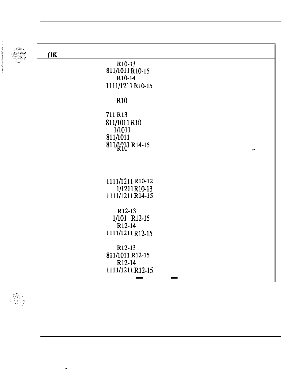
Memory calculations 73
Table 3
Software program storage requirements (continued)
Program Version Storage in K
S
Comments
UK
= 1024 words)
ICDR 711 RlO-13
0
Sll/lOll
RlO-15 0
911 RlO-14 0
1111/1211
RlO-15 0
APL-AUX 711 RlO 4.76
711 R12 4.77
711R13
5.06
811/1011
RlO 4.77
81 l/1011 R12 4.77
811/1011 R13 5.06
811/1011
R14-15 5.07
911 RlO 4.69
_.
911 R12 4.70
911 R13 5.00
911 R14 5.01
1111/1211
RlO-12 3.80
111 l/1211 RlO-13 3.70
1111/1211
R14-15 3.71
TVS 711 R12-13 0
81 l/101 1 R12-15 0
911 R12-14 0
1111/1211
R12-15 0
TOF 711 R12-13 0
811/1011
R12-15 0
911 R12-14 0
1111/1211
R12-15 0
-
continued
-
_.
I-..
~
_.
:
-:
.!,
:
I
.,,
.”
I)
Memory calculations 553-2201-151 Appendix 1
s.
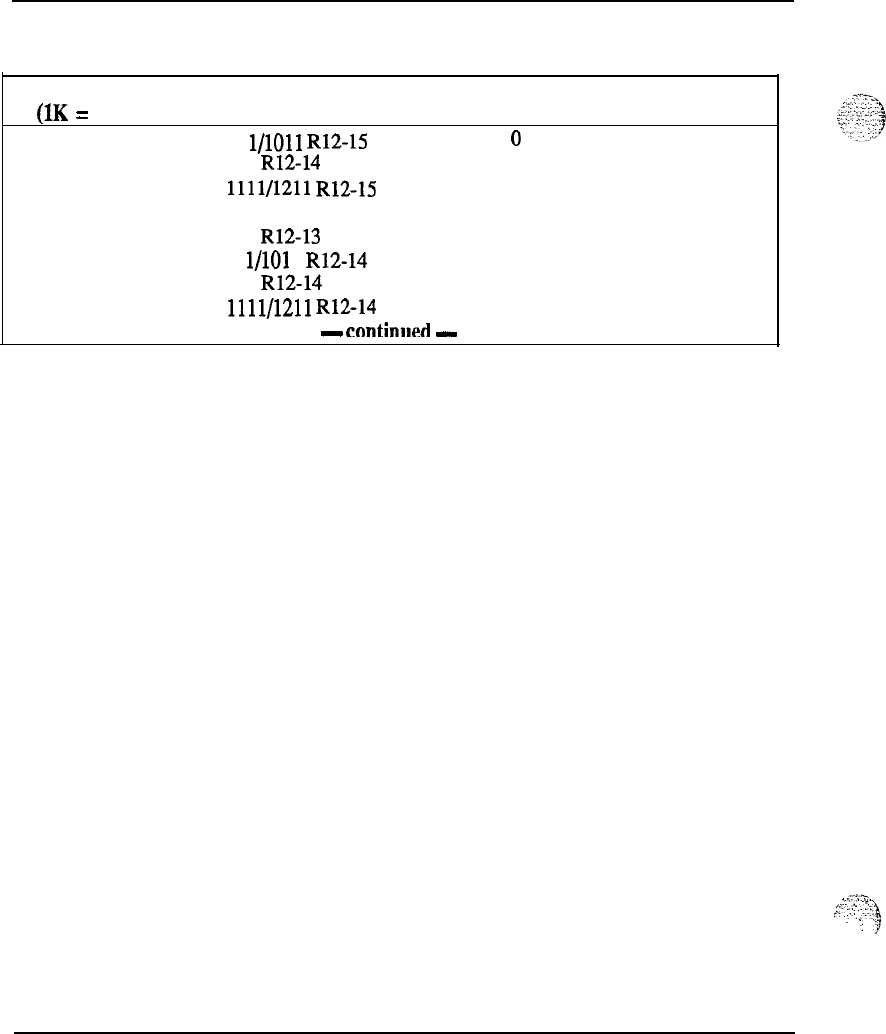
74 Memory calculations
Table 3
Software program storage requirements (continued)
Program Version Storage in K
S
Comments
(1K = 1024 words)
NKL
81 l/1011 R12-15 0
.
911 R12-14 0
1111/1211
R12-15 0
ISA ISDN PRA 711 R12-13 0Note 7for R13
81 l/101 1 R12-14 0
911 R12-14 0
1111/1211
R12-14 0
-
cnntinlml
-
g:.
:..:::;a
,..?
_’
.
!
.
.:
‘7
Memory calculations 553-2201-151 Appendix 1
. .
Memory calculations 75
Table 3
Software program storage requirements (continued)
Program Version Storage in K
S
Comments
(1K = 1024 words)
IDC 711 R12 0.37
711 R13 0.39
811/1011
R12
0.38
811/1011
R13 0.39
81 l/101 1
R14-15 0.44
911 R12 0.37
911R13
0.38
911 R14 0.43
1111/1211
R12
0.20
1111/1211 R13 0.28
1111/1211
R14-15 0.31
AUX ACD-D
711 R13 0
. .
81 l/101 1 R13-15 0
911 R13-14 0
1111/1211
R13-15 0
DCP 711 R13 0.18
811/1011 R13 0.18
---
81 l/101 1 R14-15 0.19
911 R13-14 0.19
1111/1211
R13-15 0.14
ACD Priority Agent 711 R13 0
811/1011
R13-15 0
911 R13-14 0
1111/1211
R13-15 0
EMUS 711 R13 0
81 l/1011 R13-15 0
911 R13-14
0
1111/1211
R13-15 0
-
continued
-
Memory calculations 553-2201-151 Appendix 1
.
.
76 Memory calculations
Table 3
Software program storage requirements (continued)
Program Version Storage in K
S
Comments
(1K = 1024 words)
FTC
711 R13 0
.
811/1011
R13-15 0
911 R13-14 0
1111/1211
R13-15 0
DT12 811/1011 R14 8.55
911 R14 8.43
1011 R15 8.57
1111/1211 R14 6.11
1111/1211 R15 6.12
JDMI 81 l/1011 R14-15 0
911 R14 0
1111/1211
R14-15 0
ISDN 711 R13 Note 7
811/1011 R13 20.26
811/1011 R14 23.34
911 R13 20.00
911 R14 23.02
1011 R15 35.28
1111/1211 R13 14.75
1111/1211 R14 16.95
1111/1211 R15 26.06
PRA
ISL
81 l/1011 R14-15 0
911 R14 0
1111/1211
R14-15 0
711 R13 Note 7
811/1011
R13-15 0.02
911 R13-14 0.01
1111/1211
R13-15 0.01
-
continued
-
Memory calculations 553-2201-151 Appendix 1
2.
Memory calculations 77
Table 3
Software program storage requirements (continued)
PrOgGlIll
Version Storage in K
S
Comm+ts
(1K = 1024 words)
NTWK SRVC 711 R13 Note
7-
811/1011 R13 3.57
811/1011
R14
3.97
911R13
’
3.51
911 R14 3.91
1011 R15 5.42
1111/1211
Rl?
2.56
1111/1211 R14 2.85
1111/1211
R15
3.89
DNXP 711 R13 0
811/1011
R13-15 0
911 R13-14 0
.
1111/1211
R13-15 0
CDRJZ
711 R13 0
811/1011
R13-15 0
911 R13-14 0.--
1111/1211
R13-15 0
ISDN AP 711 R13 0
81 l/101 1 R13-15 0
911 R13-14 0
1111/1211
R13-15 0
PR12 811/1011
R14
4.11
911 R14 4.03
1011 R15 4.19
1111/1211 R14 2.91
1111/1211 R15 2.97
-
continued
-
Memory calculations 553-2201-151 Appendix 1
s.
:.:.
.:.
-.
78 Memory calculations
Table 3
Software program storage requirements (continued)
Program Version Storage in K
S
Comments
(1K
=
1024 words)
ACNT
Sll/lOll
R14 0.61
_
911 R14 0.60
1011 R15 0.62
111 l/121 1 R14 0.43
1111/1211 R15 0.44
ACD Account Package
7 11 R 13
0.61
81 l/101 1 R13-14 0.61
911 R13-14 0.60
1111/1211
R13-14 0.43
-
continued
-
Memory calculations 553-2201-l 51 Appendix 1
.
.
_
,:
,
.:
.“.
-.
i.;--:,.,
y:,..
,,j
.
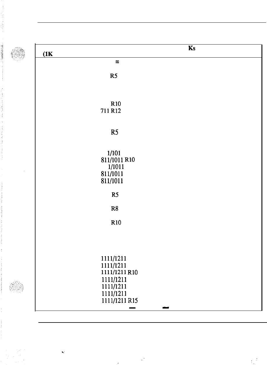
Table 3
Software program storage requirements (continued)
Memory calculations 79
Program Version Comments
(1K = 1024 words) Storage in KS
Total (base = resident + overlay area + firmware)
.
711 R4 84.82
711 R5 87.96
711 R7 100.67
711 R8 104.41
711 R9 107.50
711 RlO 114.00
711R12
130.22
711 R13 141.05
811 R4 88.24
811 R5 93.31
811 R7 105.64
811 R8 107.95
. .
81 l/101 1 R9 134.73
Sll/lOll
RlO 119.84
81 l/1011 R12 122.81
811/1011 R13 145.52
811/1011 R14 165.42
911 R4 87.26
---
911 R5 93.42
911 R7 105.84
911 R8 108.04
911 R9 110.41
911 RlO 115.42
911 R12 128.46
911 R13 139.66
911 R14 164.57
1011 R15 188.92
1111/1211 R8 85.66
1111/1211 R9 96.17
1111/1211
RlO 100.42
1111/1211 R12 110.37
1111/1211 R13 114.94
1111/1211 R14 133.38
1111/1211R15 164.57
-
continued
-
Memory calculations 553-2201-151 Appendix 1
c.
:
:
,:
.
.
80
Memory calculations
Table 3
Software program storage requirements (continued)
Program Version Storage in KS Comments
(1K
No. of R/W Modules (base) (Note 2)
.
711
1
(56k)
81 l/101 1
1
(56k)
911
1
(56k)
1111/1211
1
(56k)
-continued
-
Memory calculations 553-2201-151 Appendix 1
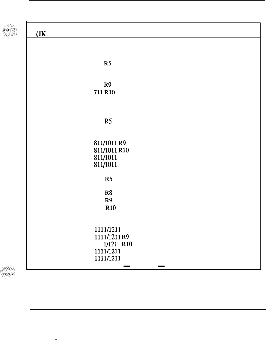
Table 3
Software program storage requirements (continued)
Memory
calculations
81
Program
Version Storage in Ks Comments
(1K = 1024 words) Overflow (base) (Note 3)
.
711 R4 28.82
711 R5 31.96
711 R7 44.67
711 R8 48.41
711 R9 51.50
711RlO
58.00
711 R12 74.22
711 R13 85.05
811 R4 32.94
811 R5
37.3 1
811 R7
.
49.64
811 R8 51.95
Sll/lOll
R9 56.65
811/1011
RlO 63.84
811/1011
R12
78.73
811/1011 R13 89.52
---
911 R4 31.26
911 R5 37.42
911 R7 49.84
911 R8 52.04
911 R9 54.41
911 RlO 59.42
911 R12 72.46
911 R13 83.66
1111/1211 R8 29.66
1111/1211
R9 40.16
111 l/121 1 RlO 44.42
1111/1211 R12 54.37
1111/1211 R13 58.94
-
continued
-
Memory calculations
553-2201-151 Appendix 1
.
.
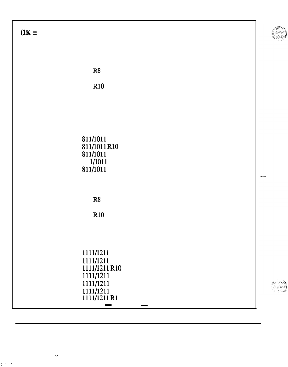
82 Memory calculations
Table 3
Software program storage requirements (continued)
Program Version Storage in K
S
Comments
(1K = 1024 words) Total of All Optional Packages (Note 4)
-
711 R4
93.81
711 R5 100.26
711 R7 128.01
711 R8 142.29
711 R9 136.06
711 RlO 162.92
711 R12 174.29
711 R13 186.74
811 R4 93.92
811 R5 100.80
811 R7 127.37
811 R8 144.01
811/1011
R9 135.12
811/1011
RlO 161.20
Sll/lOll
R12 194.96
81 l/1011 R13 209.93
811/1011 R14 232.04
911 R4 92.77
911 R5 99.68
911 R7 121.58
911 R8 142.39
911 R9 133.69
911 RlO 159.96
911 R12 192.49
911 R13 207.76
911 R14 229.67
1011 R15 275.69
1111/1211
R8
112.29
1111/1211
R9
106.13
1111/1211
RlO 126.92
1111/1211 R12 155.19
1111/1211 R13 154.70
1111/1211 R14 170.68
1111/1211
Rl
207.69
-
continued
-
Memory calculations 553-2201-151 Appendix 1
Y
.:.’
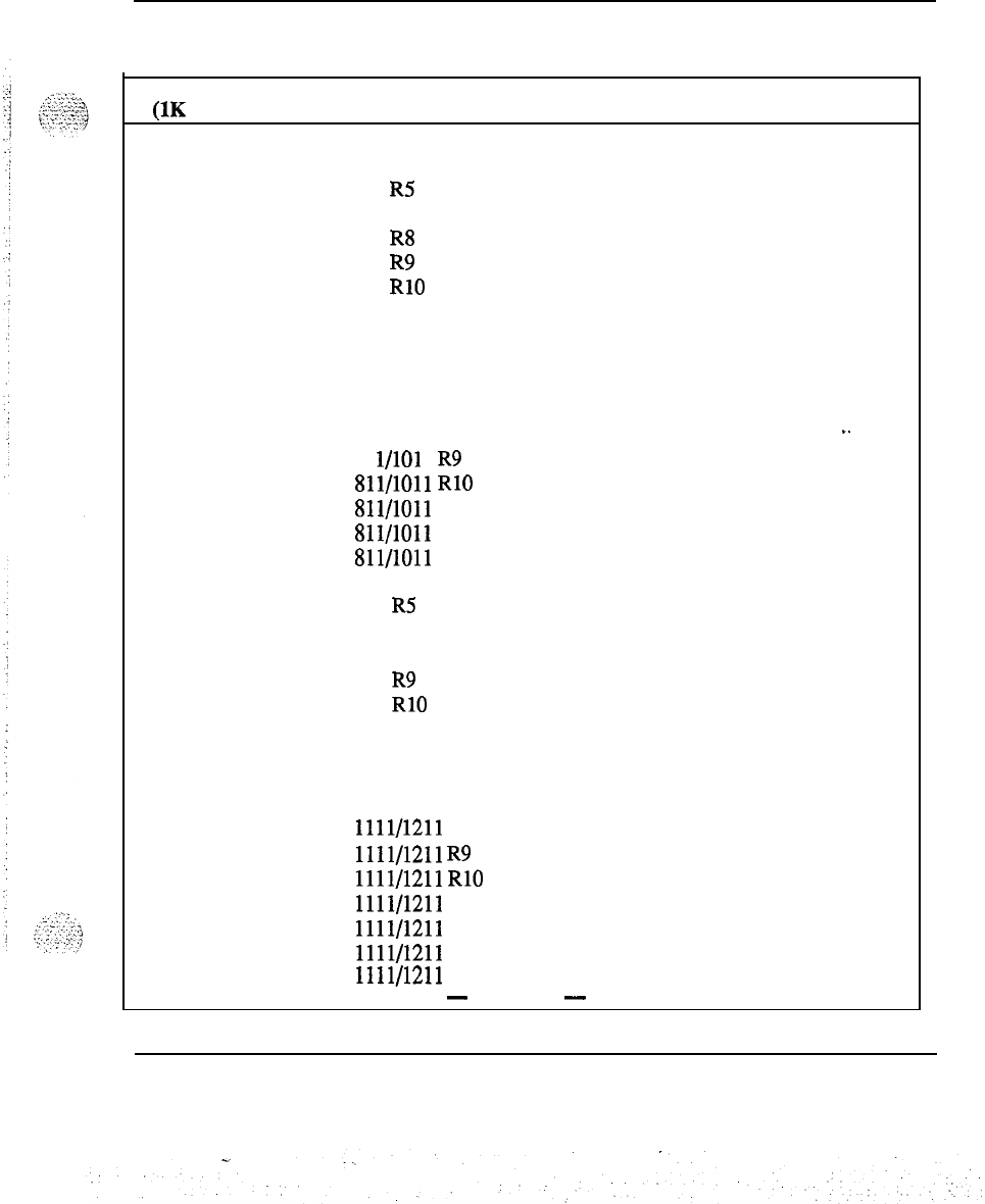
Memory calculations 83
Table 3
Software program storage requirements (continued).
Program
Version
(1K = 1024 words) Storage in K
S
Comments
Overflow (base + all optional packages). (Note 4)
.
711 R4 122.63
711 R5 132.22
711 R7 172.68
711 R8 190.70
711
R9 187.56
711
RlO 220.92
711 R12 248.51
711 R13 271.79
811 R4 126.16
811 R5 138.11
811 R7 177.01
811 R8 195.98
_.
81 l/101 1 R9 191.77
811/1011
RlO 225.04
811/1011
R12
273.69
811/1011
R13
299.45
Sll/lOll
R14
397.46
911 R4 124.03 ---
911
R5 137.10
911 R7 171.42
911 R8 194.43
911
R9 188.10
911
RlO 219.38
911 R12 264.95
911 R13 291.42
911 R14 394.25
1011 R15 464.61
1111/1211
R8
141.95
1111/1211
R9 146.30
1111/1211
RlO 171.34
1111/1211
R12
209.56
1111/1211
R13
213.64
1111/1211
R14
304.06
1111/1211
R15
372.26
-
continued
-
Memory calculations 553-2201-151 Appendix 1
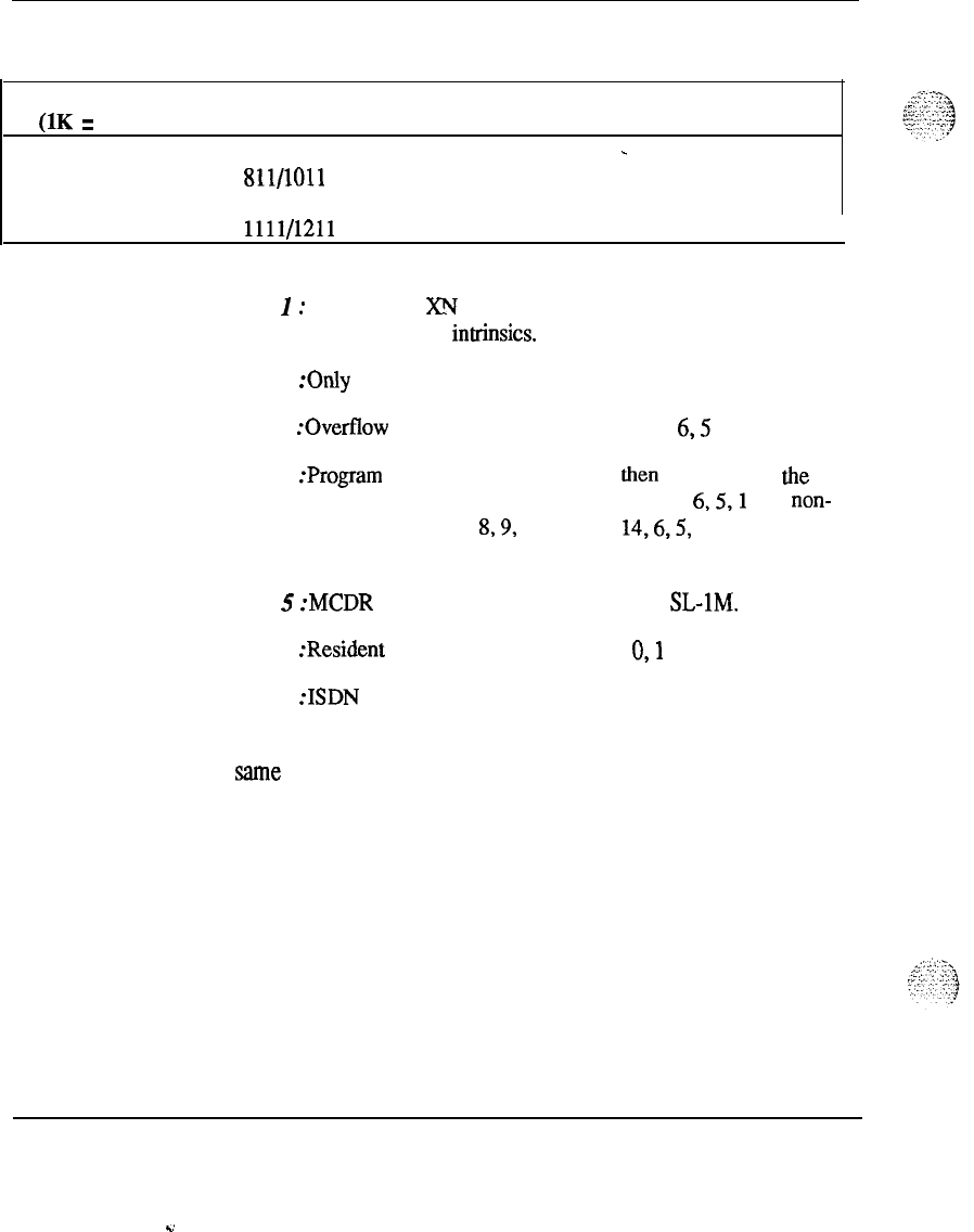
84 Memory calculations
Table 3
Software program storage requirements (continued)
Program Version Storage in K
S
Comments
(1K
=
1024 words)
ROM 711 8.0
-
811/1011 8.0
911 8.0
1111/1211 8.0
I
Note
I
:
On XL and XN systems, Read/Write fiiware is represented
by the set of High-Level intrinsics.
Note 2
:Only
56K of the first program store is available.
Note
3 :Overflow into protected data store or page
6,5
and then
1.
Note 4 :Program is first loaded into page 2, then overflow into the
pages (if equipped) in the following sequences: page
6,5,1
(for non-
enhanced systems); or page
8,9,
10, 12, 13,
14,6,5,
1 (for enhanced
systems).
Note
5
:MCDR
(Mini CDR) is only available for SL-1M.
Note
6
:Resident
Programs include packages
0,l
and 2.
Note 7
:ISDN
features are not available on 711 version.
Note 8: TSET can only be used when DSET is available and uses the
same memory.
Note 9: 1011 software must have “SLST” package turned ON.
Memory calculations 553-2201-151 Appendix 1
.d
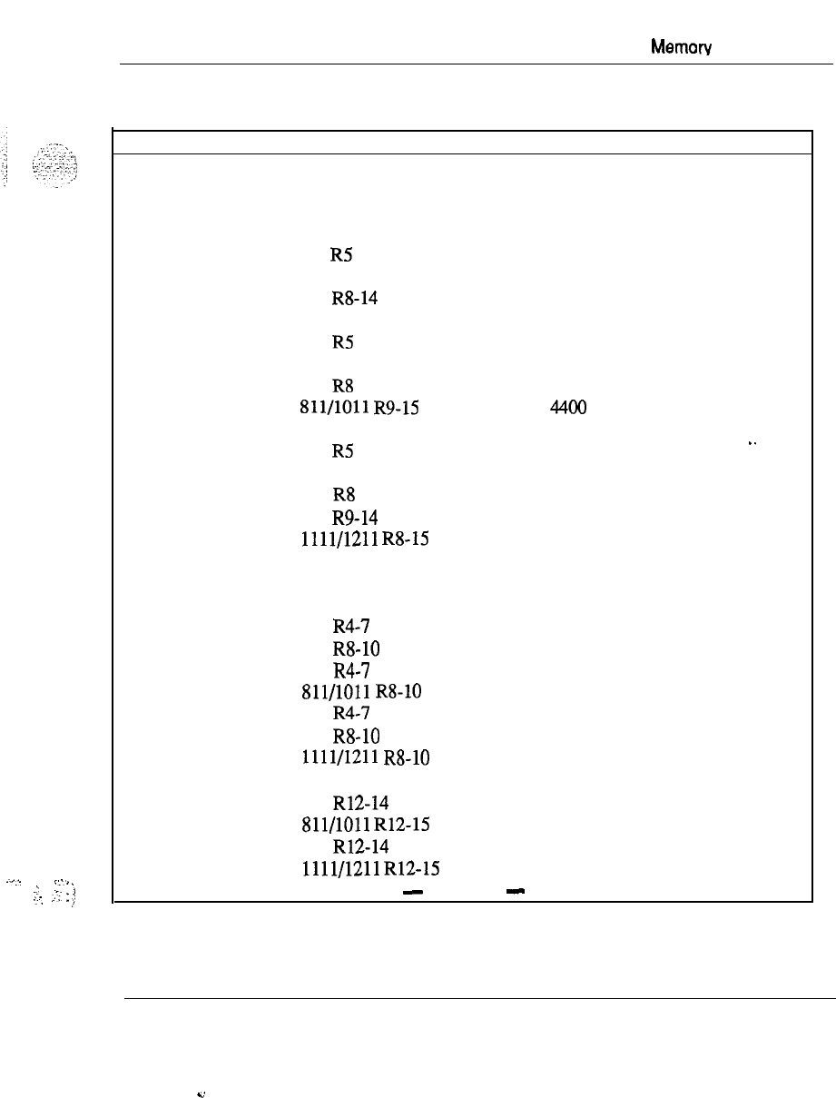
Memow
calculations 85
..,...
_..,
-‘
I
‘,
,..-,
:
;-:.
:
,;:
Table 4
Unprotected data storage requirements
Feature Version Storage in Words Comments
Fixed amount of storage required for system operation. .
711 R4
3748
711
R5 3983
711 R7
4386
711 R8-14
4397
811 R4 3751
811 R5 3986
811 R7 4386
811 R8 3398
811/1011
R9-15 4400
911 R4 5632
911 R5 5867
911 R7 6267
911 R8 6279
911 R9-14 6281
1111/1211
R8-15 7487
For EACH of the following:
1
item
only
1
item
only
1
item
only
1
item
only
1
item
only
1
item only
1
item only
1
item only
1
item only
1
item only
1
item only
..
1
item only
1
item only
1
item only
1
item only
---
500 and 2500 Sets
711 R4-7
3.5
711 RS-10 4.5
811 R4-7
3.5
811/1011
R8-10 4.5
911 R4-7
3.5
911 R8-10 4.5
1111/1211
R8-10 4.5
500
sets
711 R12-14 4.5
Sll/lOll
R12-15 4.5
911 R12-14 4.5
1111/1211
R12-15 4.5
-
continued
-
Memory calculations
553-2201-151 Appendix 1
.4
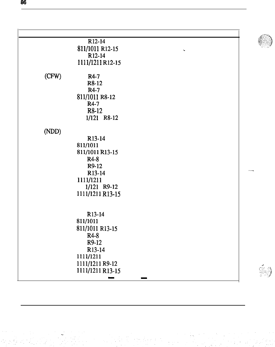
86
Memory calculations
Table 4
Unprotected data storage requirements (continued)
Feature
2500 sets
Version Storage in Words
711 R12-14 5.5
Comments
2500 Sets
(CFW)
SL-1 Sets (NDD)
SL-1 Sets (ADD)
811/1011
R12-15
911 R12-14
1111/1211
R12-15
711 R4-7
711 R8-12
811 R4-7
811/1011
R8-12
911 R4-7
911 R8-12
111 l/121 1 R8-12
711 14.25
711 R13-14 16.25
811/1011 14.25
811/1011
R13-15 16.25
911 R4-8 14.25
911 R9-12 15.25
911 R13-14 16.25
1111/1211
R8
14.25
111 l/121 1 R9-12 15.25
1111/1211
R13-15 16.25
711 15.25
711 R13-14 18.25
811/1011 15.25
811/1011
R13-15 18.25
911 R4-8 15.25
911 R9-12 16.25
911 R13-14 18.25
1111/1211
R8
15.25
1111/1211
R9-12 16.25
1111/1211
R13-15 18.25
5.5
-
5.5
5.5
4.5
5.5
4.5
5.5
4.5
5.5
5.5
-
continued
-
Memory calculations 553-2201-l 51 Appendix 1
,..
,_:
:.
:
:
..:.:
2:;
j
:.
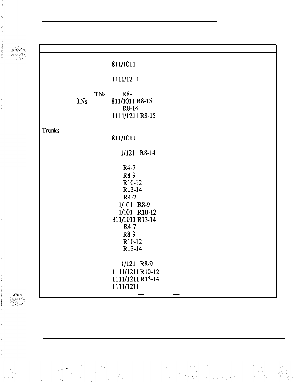
Memory calculations 87
Table 4
Unprotected data storage requirements (continued)
Feature Version Storage in Words Comments
Add-on K/L Strips 711
10
811/1011
-10
I.
911
10
1111/1211
10
Data
Service Access TNs 7 11
R8-
13 (Note 15)
VMS Access
‘INS
811/1011
R8-15
911 R8-14
1111/1211
RS-15
-hlUkS
711
811/1011
911
111 l/121 1 R8-14
(Note 1)
.
Attendants
711
R4-7 89
711 R8-9 92
711 RlO-12 93
711 R13-14 97
811 R4-7 95
81 l/101 1 R8-9 98
81 l/101 1 RlO-12 99
Sll/lOll
R13-14
103
911
R4-7 95
911
R8-9 98
911 RlO-12 99
911 R13-14
103
1011 R15 107
111 l/121 1 R8-9 98
1111/1211
RlO-12 99
1111/1211
R13-14
103
1111/1211 R15
107
-
continued
-
Memoty calculations 553-2201-151 Appendix 1
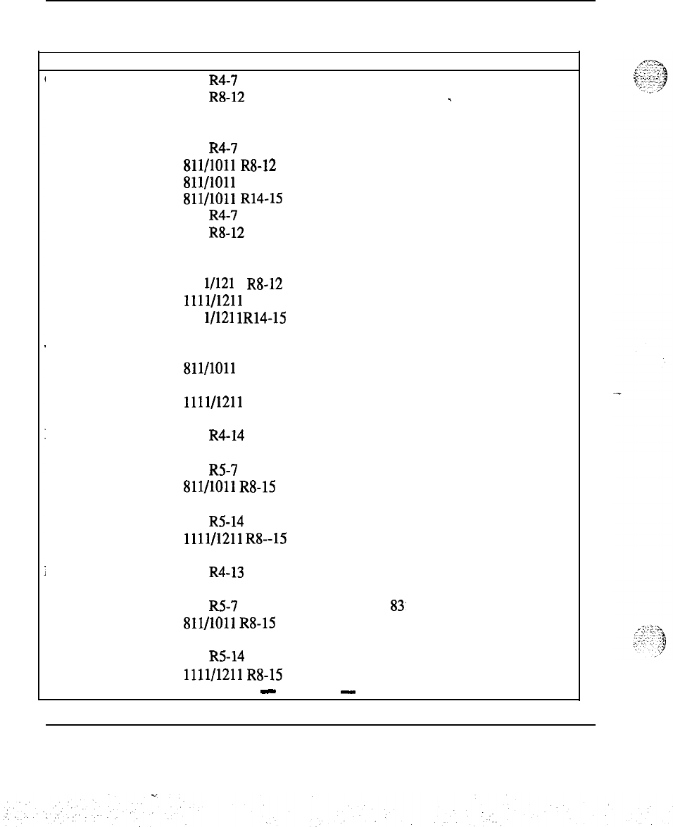
88 Memory calculations
Table 4
Unprotected data storage requirements (continued)
Feature
Customers
Version Storage in Words Comments
711 R4-7 137
711 R8-12 152
-
711 R13 142
711 R14
144
811 R4-7
137
811/1011
R8-12 152
811/1011
R13
142
811/1011
R14-15
144
911 R4-7
137
911 R8-12 152
911 R13
142
911 R14 192
111 l/121 1 R8-12 152
1111/1211
R13
142
111 l/121
lR14-15
192
Trunk Routes 711
811/1011
911
1111/1211
(Note 2)
Network-Local 711 R4-14 63
811 R4 65
811 R5-7 66
811/1011
R8-15 66
911 R4 65
911
R5-14 66
1111/1211
R8--15
66
Network-RPE
711
R4-13 80
811 R4 82
811 R5-7
83’
811/1011
R8-15 83
911 R4 82
911 R5-14 83
1111/1211
R8-15 83
-
continued
-
Memory calculations 553-2201-l 51 Appendix 1
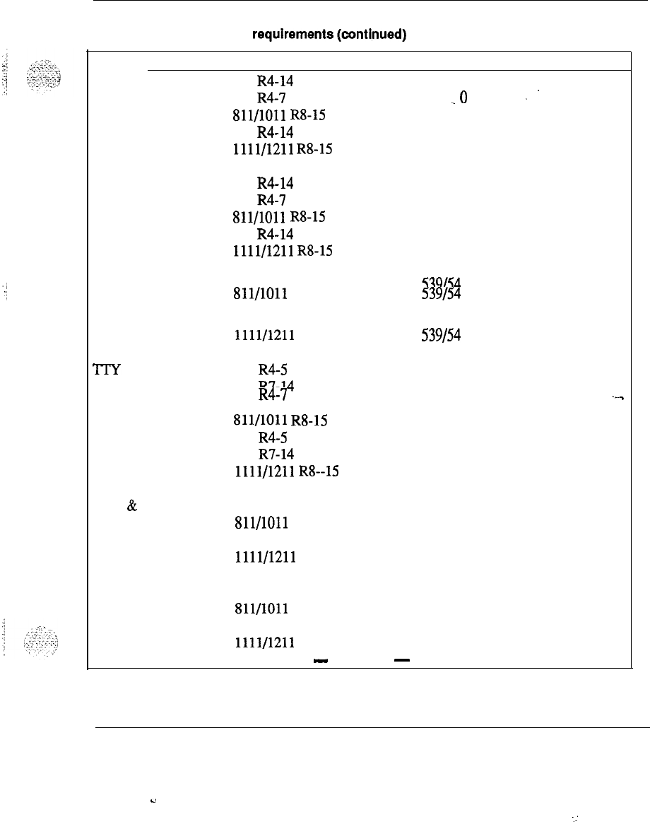
Memory
calculations 89
Table 4
Unprotected data storage requirementstcontinued)
Feature Version Storage in Words Comments
Junctor Group Pairs 711 R4-14 0
(Note 3) 811 R4-7
.o
..
811/1011
R8-15 0
911 R4-14 74
1111/1211
R8-15 74
Peripheral Signaling 711 R4-14 36
811 R4-7 52
811/1011
R8-15 52
911 R4-14 52
1111/1211
R8-15 52
Secondary Tape 711 539154 1
811/1011
539154 1
. .
911 5391541
1111/1211
539154 1
711 R4-5 (Note 4)
711 R7-14
811 R4-7 -.-
811/1011
R8-15
911 R4-5
911 R7-14
1111/1211
R8--15
Tone
&
Digit Switch
7 11
57
811/1011 59
911 59
1111/1211 59
MF Sender 711 57
811/1011 59
911 59
1111/1211 59
-
continued
-
Memory calculations 553-2201-l 51 Appendix 1
-.
..:
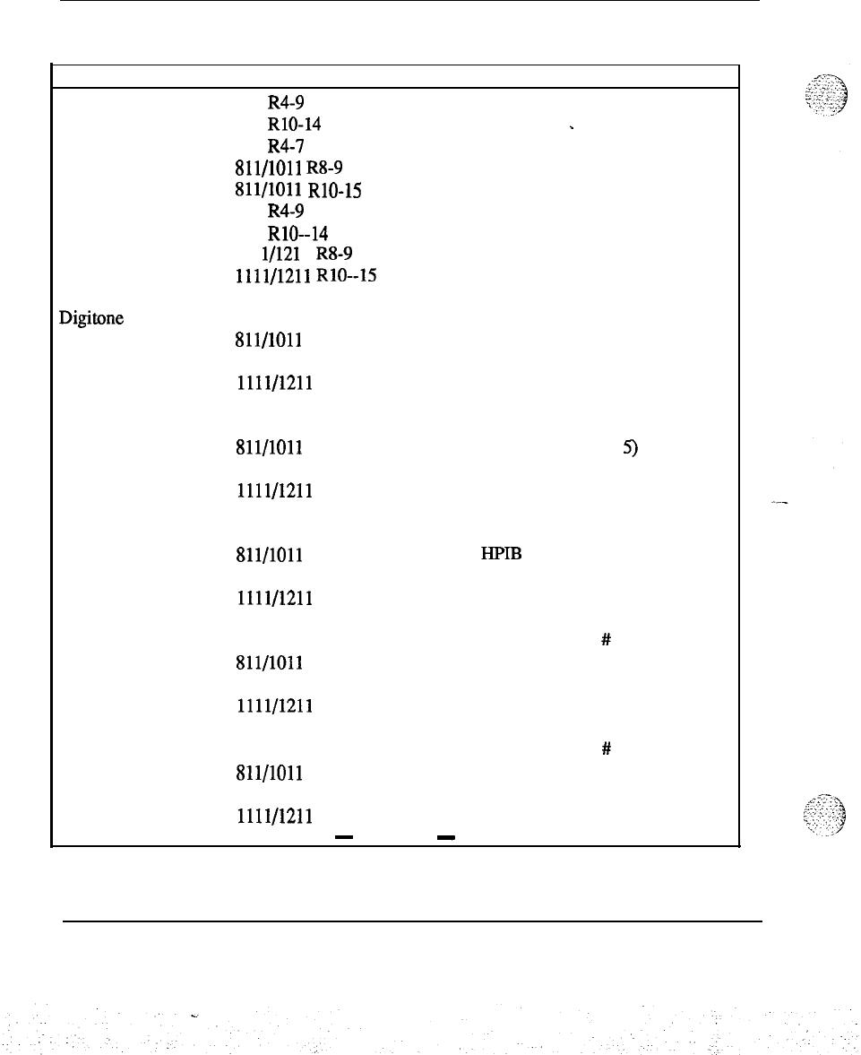
90 Memory calculations
Table
4
Unprotected data storage requirements (continued)
Feature
Conference
Digitone Receiver
Version
711 R4-9
711
RlO-14
811 R4-7
811/1011
R8-9
811/1011
RlO-15
911 R4-9
911 RlO--14
111 l/121 1 R8-9
1111/1211
RlO--15
711
811/1011
911
1111/1211
Storage in Words Comments
141
145
-
143
143
147
143
147
143
147
6
6
6
6
LPIB 711
4x LPIB
811/1011
4x LPIB
911
4x LPIB
1111/1211
4x LPIB
1 item
Note 5)
HPIB 711
4x HPIB
811/1011
4x
HPIB
911
4x HPIB
1111/1211
4x HPIB
1 item
(Note 5)
PBXOB 711
4 x PBXOB
811/1011
4
x PBXOB
911 4x PBXOB
1111/1211
4x PBXOB
x # Periph. Signals
(Note 5)
BCSOB 711
4 x BCSOB
811/1011
4x BCSOB
911 4
x BCSOB
1111/1211
4
x BCSOB
-
continued
-
x
#
Periph. Signals
(Note 5)
Memory calculations 553-2201-151 Appendix 1

Memory calculations 91
Table 4
Unprotected data storage requirements (continued)
(Note
11)
Feature Version Storage in Words Comments
ACD 711 (Note
6)
811/1011
911
1111/1211
ACD Enhancement 711
Sll/lOll
911
1111/1211
Extended Agent
Observe 711
811/1011
911
1111/1211
1
per
ACD
POS
. .
CMAC 711 534
811/1011 534
911 534
1111/1211 534
1 item
---
NARS/BARS/CDP 711 (Note 7)
811/1011
911
1111/1211
-
continued
-
Memory calculations 553-2201-l 51 Appendix 1
:
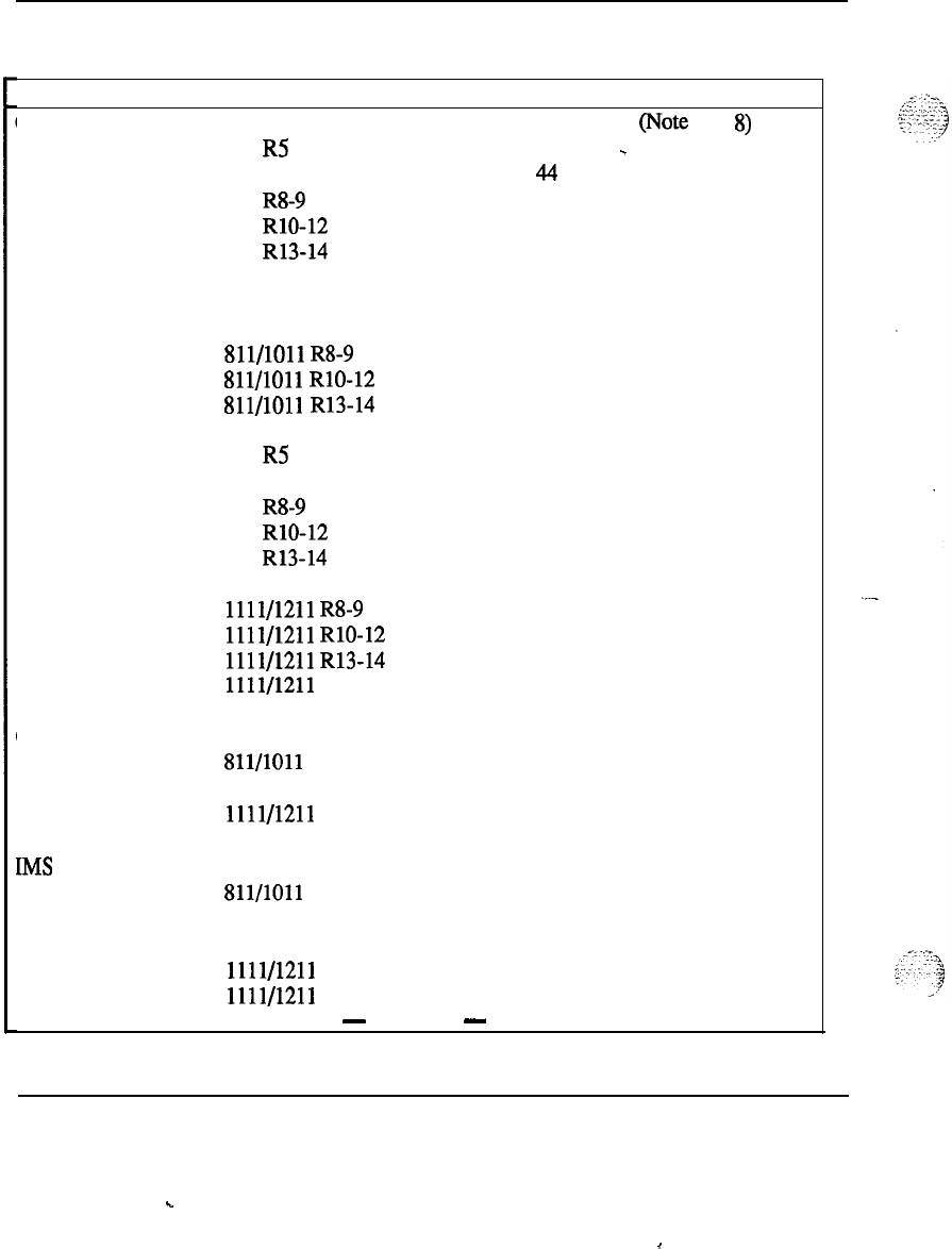
92 Memory calculations
Table 4
Unprotected data storage requirements (continued)
Feature
Call Register
Version Storage in Words Comments
711 R4 40 Wote
8)
711 R5 41
-
711 R7 44
711 RS-9 45
711 RlO-12 48
711 R13-14 61
811 R4 41
811 R5 42
811 R7 45
811/1011
R8-9 46
811/1011
RlO-12 49
811/1011
R13-14 62
911 R4 41
911 R5 42
911 R7 45
911 RS-9 46
911 RlO-12 49
911
R13-14 62
1011 R15 64
1111/1211
R8-9 46
1111/1211
RlO-12 49
1111/1211
R13-14 62
1111/1211
R15
64
CPRK 711
811/1011
911
1111/1211
(Note 9)
IMS 711 28
1 list
per
811/1011 28 (Note 10)
911 28
1011 R15 16
1111/1211 28
1111/1211
R15
16
-
continued
-
Memory calculations 553-2201-151 Appendix 1
.
.
I
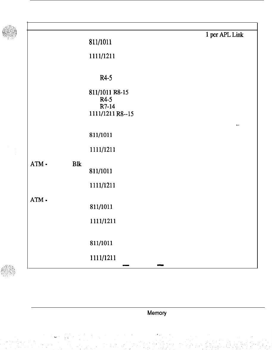
Memory calculations 93
Table 4
Unprotected data storage requirements(continued)
Feature Version Storage in Words Comments
APL 711 179
1perAPLLink
811/1011 179
911 179
1111/1211
179
TDET 711
10
811 R4-5
10
811 R7
11
811/1011
R8-15
11
911 R4-5 10
911 R7-14
11
1111/1211
R8--15
11
DTI 711
811/1011
911
1111/1211
(Note 12) ..
ATh4
-
Schedule Blk 711 (Note 13)
811/1011
911
1111/1211
ATM
-
Data Blk 711 (Note 13)
811/1011
911
1111/1211
Digital Sets 711 (Note 14)
Sll/lOll
911
1111/1211
-
continued
-
Memoty
calculations 553-2201-151 Appendix 1

94 Memory calculations
Table 4
Unprotected data storage requirements (continued)
Feature
Multi-Tenant
Version
711
811/1011
911
1111/1211
Storage in Words
32
32
_
32
32
Comments
(Note 16)CSL 711
811/1011
911
1111/1211
-
continued
-
Memory calculations 553-2201-l 51 Appendix 1
.
.
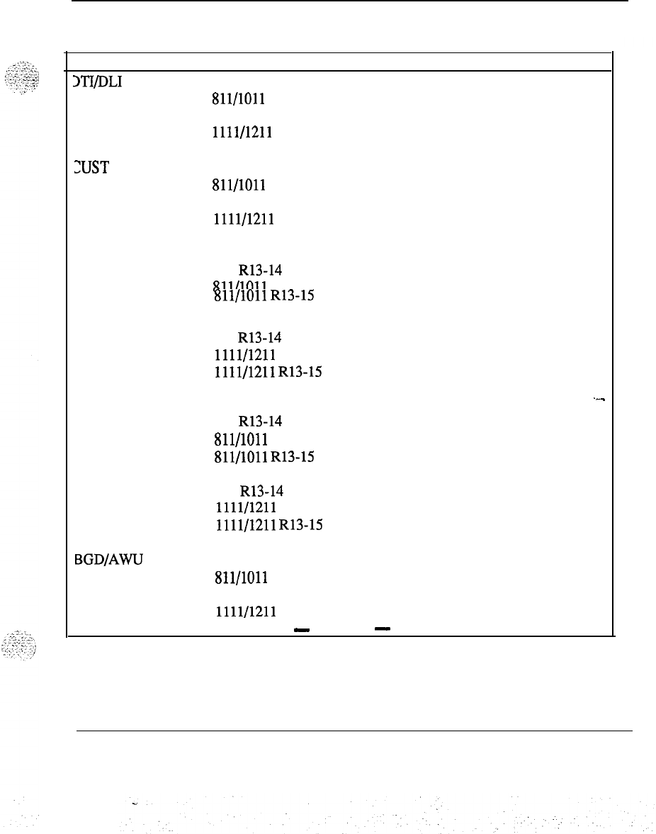
Memory calculations 95
Table 4
Unprotected
data
storage requirements (continued)
Feature
sl-I/DLI Loops
Version
711
811/1011
911
1111/1211
Storage in Words Comments
(Note 17)
XJST 711
13
811/1011
13
911
13
1111/1211
13
BGD
711 60
711 R13-14 66
811/1011 60
811/1011
R13-15 66
.
911 60
911 R13-14 66
1111/1211 60
1111/1211
R13-15 66
BGD Disp 711
6x
DNIS
1
item .--
711 R13-14
9x DNIS
(Note 18)
Sll/lOll
6x DNIS
811/1011
R13-15
9x DNIS
911
6x
DNIS
911 R13-14
9x DNIS
1111/1211
6x
DNIS
1111/1211
R13-15
9x DNIS
BGDIAWU
Loop
711 100
1
item
811/1011 100
911 100
1111/1211 100
-
continued
-
Memory calculations 553-2201-l 51 Appendix 1
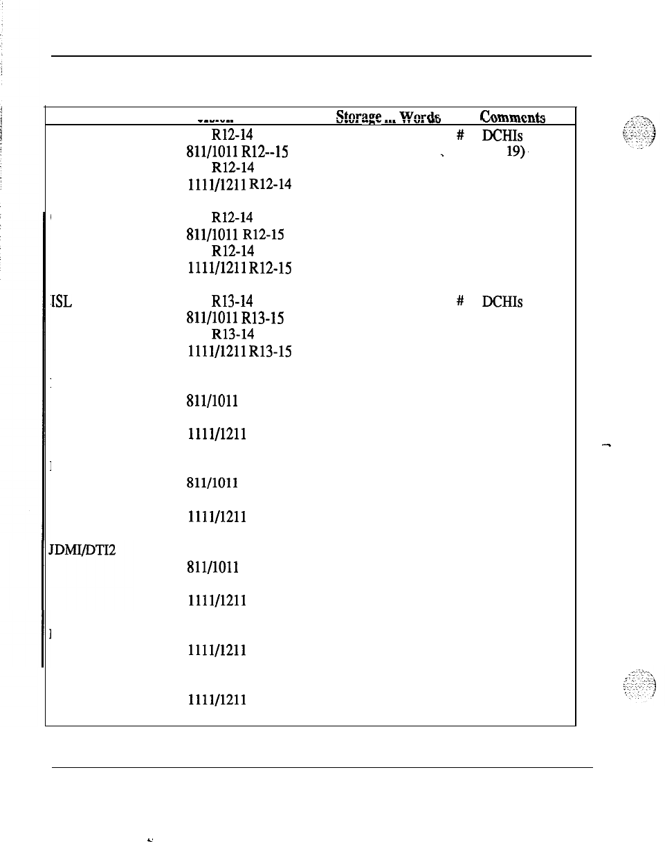
96 Memory calculations
Table 4
Unprotected data storage requirements (continued)
Feature Version
Stnmw
in
Wnrdc rnmmentr
ISDN PRA
_
_
-_
_
__
711 R12-14
811/1011
R12--15
911 R12-14
1111/1211
R12-14
uI.,-
..-., ---
. .
“_
-”
V”ur..lr.1W
#
of
DCHIS
_
(Note
19).
Overlay Data Space 711 R12-14
260
811/1011
R12-15
260
911 R12-14
260
1111/1211
R12-15
260
ISL 711 R13-14
#
of
DCHIs
811/1011
R13-15 (Note 19)
911 R13-14
1111/1211
R13-15
ISDN Utility 711
811/1011
911
1111/1211
(Note 21)
ISDN PR12 711
811/1011
911
1111/1211
(Note 19)
711
Sll/lOll
911
1111/1211
R13
Note 22
EBLF 1011 R15
1111/1211
R15
Note 23
EOVF 1011 R15
1111/1211
R14
Note 24
Memory calculations 553-2201-l 51 Appendix 1
-
s.
Memory calculations 97
Note I :
The size of the trunk block is
calhlated
from:
CT + X (words),
where:
CT = 7 words (3 average card block + 4 trunk timing block)
X = (see the following table).
Trunk Types Value of X
NorXN
Other
RLA
AUTOVON
ADM
Others
15 14
8 8
14 13
5 5
10
(Note) 10 (Note)
Note:
These numbers are for Release 12.
Memory calculations 553-2201-151 Appendix 1
.
.
:
.’
‘.
.A.
.-...
:
98 Memory calculations
For Release 13 through 14, the size of the trunk block is calculated from:
CT + X (words) + Y
where:
CT = 9 words (5 average card block + 4 trunk timing block)
X = (see the following table)
Y = 0 if the trunk belongs to a route which does not have CDR or which has
CDR with dialed digits.
= 9 if the trunk belongs to a route which has CDR with outpulsed digits.
Trunk Types Value of X
MS Other
RAN
RLA
AUTOVON
ADM
Others
(includes ISA)
5 5
14
15
88
15 15
10 10
Note
2 :
The size of the route block is calculated from:
24 + ceiling (number of members/l6) (words).
Releases 12 and 13
27 + ceiling (number of
membeM6)
(words).
Releases 14 through 15
43 + ceiling (number of members/l6) (words)
Note 3 : The number of Junctor Group Pairs is (N x (N-1)/2 in a system
with N network groups.
Memory calculations 553-2201-l 51 Appendix 1
Memory calculations 99
Note
4 : The size of the TI’Y blocks is calculated from:
For Releases 4 and 5:
141+
x (words),
where: x = 8 for CDR ‘ITYs; 128 otherwise.
For Releases 7 through 15:
t + x (words),
where:
t = 16 (size (ITYI@BLOCK) + 128 (TTY output buffer) = 144
and x = the following table
CDR link:
HS link:
APL link:
PMS Link:
other:
Input Buffer
128
128+
128+
20+
8
Data
15
(179 +
2
Output
Q
4)
I
1
---
Note
5 : The size of the Input/Output buffers is specified in “messages”.
Each message uses 4 words of unprotected data store. The recommended
size for I/O buffers is:
LPIB
(Low Priority Input Buffers)
HPIB
(High Priority Input Buffers)
= 96 messages
= M,
LE:16
messages
S, MS: 16 messages
N, VLE: 32 messages
XL:16 x # of groups
XN32
x # of groups
PBXOB (Non
SLl
Output Buffers)
BCSOB
(SLl
Output Buffers)
= 160 messages
= 160 messages
Memory calculations 553-2201-l 51 Appendix 1
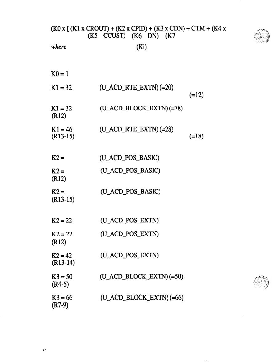
100 Memory calculations
Note 6 :
For ACD features the following additional storage is required
(total for system):
(KOx[(K1xCROUT)+(K2xCPID)+(K3xCDN)+CTM+(K4x
CRT)] ) + (K5 x CCUST) + (K6 x DN) + (K7 x PID)
where the multiplication constants (Ki) are:
KO=O
KO=l
K1=32
K1=32
@W
K1=46
(R13-15)
K2=
11
K2=
11
(Rw
K2=
14
(Rl3-15)
K2=22
K2=22
0712)
K2=42
(Rl3-14)
K3=50
(R4-5)
K3=66
o-9)
if ACD-C package is not equipped,
if ACD-C package is equipped.
size
(U-ACD-RTE-EXTN)
(=20)
+ word offset (TRUNK-SEIZE-TIME) (=12)
size
(U-ACD-BLOCK-EXTN)
(=78)
size
(U-ACD-RTl-EXTN)
(=28)
+ word offset (TRUNK-SEIZE-TIME) (=18)
if long report is selected.
size
(U-ACDJOSBASIC)
(= 11)
size
(U-ACDJOSBASIC)
(= 13)
size
(U-ACD-POSBASIC)
(= 14)
if short report is selected
size
(U-ACD-POS-EXTN)
(= 22)
size
(U-ACD-POS-EXTN)
(= 39)
size
(U~ACDJOS~EXTN)
(= 42)
size
(U-ACD-BLOCK-EXTN)
(=50)
size
(U-ACD-BLOCK-EXTN)
(=66)
Memory calculations 553-2201-151 Appendix 1
k.
:
. .
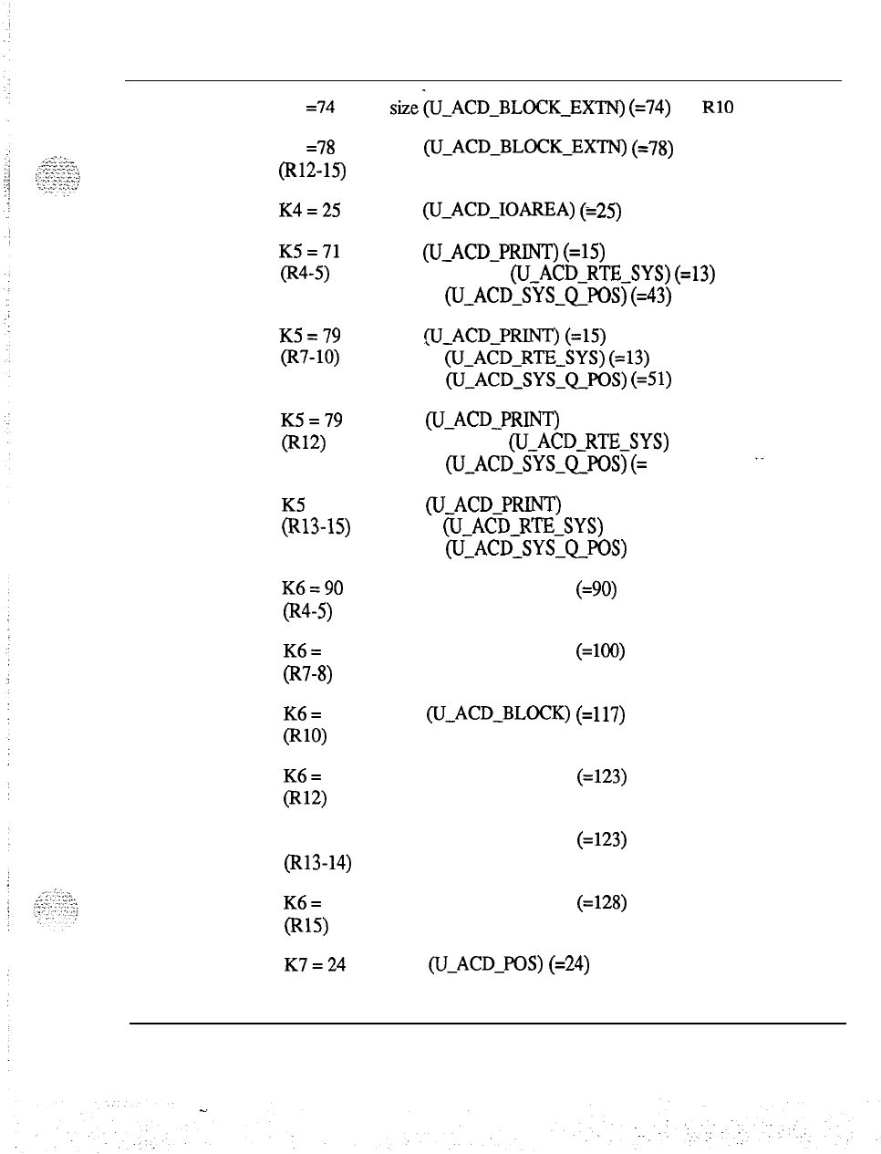
Memory calculations 101
K3 =74
K3 =78
(R12-15)
K4=25
size(U_ACD-BLOCK-EXTN)
(=74)
for
RlO
size
(U-ACD-BLOCK-EXTN)
(=78)
K5=71
(R4-5)
K5=79
(R7-10)
K5=79
(Rw
K5 = 114
(R13-15)
K6=90
cR4-5)
size
(U-ACD-IOAREA)
(*25)
size
(U-ACD-PRINT)
(=15)
+ size
(U-ACD-RTE-SYS)
(=13)
+ size
(U-ACD-SYS-QPOS)
(=43)
size
(U-ACD-PRINT)
(=15)
+ size
(U-ACD-RTE-SYS)
(=13)
+ size
(U-ACD-SYS-QPOS)
(=51)
size (U-ACD-PRINT) (= 19)
+ size
(U-ACD-RTE-SYS)
(= 34)
+ size
(U-ACD-SYS-QJOS)
(=
57)
size
(U-ACD-PRINT)
(= 20)
+ size
(U-ACD-RTI-SYS)
(= 34)
+ size
(U-ACD-SYS-QPOS)
(= 60)
size (U-ACD-BLOCK)
(=90)
K6=
100
(R7-8)
size (U-ACD-BLOCK)
(=lOO)
K6=
117
(Rw
size
w-ACD-BLOCK)
(=117)
K6=
118
0312)
size (U-ACD-BLOCK)
(=123)
K6 = 123
(Rl3-14)
size (U-ACD-BLOCK)
(=123)
K6=
128
(Rl5)
size (U-ACD-BLOCK)
(=128)
K7=24
size
(U-ACD-POS)
(=24)
Memory calculations 553-2201-l 51 Appendix 1
102 Memory calculations
K7=29
size
(U-AC&POS)
(= 29)
(Rl3-15)
+ 2 for DN Expansion
+ 1 for
ACD-ACNT-CODE
Kg=48
(Rl3)
for NT, RT, and XT systems
K8=48
(Rl4-15)
for XT, and NT
KS=32
(R13-15)
for XN, and ST systems
and the variables are represented by:
CCUST = total no. of customers with ACD-C package
CDN = total no. of ACD DNs for ACD-C customers
CPID = total no. of AGENT POSITION
S
for ACD-C customers
CROUT = total no. of ACD routes in ACD-C customers
CTM = total no. of TRUNK members in CROUT
DN = total no. of ACD DNs (for the system)
PID = total no. of AGENT POSITION
S
(for the system)
CRT = total no. of ACD CRTs.
Memory calculations 553-2201-l 51 Appendix 1
%.

Memory calculations 103
Note
7 : The unprokcted data store requirements (on a per-customer basis)
for NARS/BARS/CDP:
2x(8xRL+6xNCOS)Release4
2 x (12 x RL + 6 x NCOS) Releases 5-8
-
2 x (16 x RL + 6 x NCOS) Releases 9-12
If FCBQ
&
OHQ is equipped:
2x(11
xRL+
lOxNCOS)Release4
2 x (17 x RL + 10 x NCOS) Releases 5-8
2 x (21 x RL +
i0
x NCOS) Releases 9-12
Releases 13 through 15
If OHQ or MCBQ is equipped:
RLSZE
+ NCOSIZE + QROUTSIZE
Otherwise:
RLSIZE + NCOSIZE
where:
RL
FUSIZE = number of route lists
=2x(45xRL)(FCBQ&OHQ
equipped)
= 2 x (40 x RL) (otherwise)
NCOS
NCOSIZE = number of NCOS defined
= 2 x (1045 x NCOS) (RLBQ
&
OHQ
equipped)
QROUTE
QROUTESIZE
= 2 x (6 x NCOS) (otherwise)
= number of routes with either CBQ or OHQ
=2x(7xQROUTE)
Memory calculations 553-2201-151 Appendix 1

104 Memory calculations
Note 8 : N, the recommended number of Call Registers is:
N = (T + 815)/33.8 + M
where:
T=A/2xCx1.42-B.
M = the number of ACD incoming trunks.
A = the total voice loop traffic in CCS.
B = M x
l(1
is average CCS per ACD trunk).
C = the total call register traffic factor
The Total Call Register Traffic Factor is equal to 1 + any of the following
factors:
0.037 if CDR Charge Account
0.074 if Authorization Code
0.037 if Parallel CDR Ports Per Customer
0.150 if NARS/BARS/CDP
0.150 if FCBQ and OHQ
0.033 if ACD RAN
0.019 if Telset Messaging
0.140 if
&Is
0.083 if Ring Again
0.033 if Music Trunk
0.067 if CPRK
0.003 if NFCR
0.039 if ESN Signalling
0.0 if Stored Number
Redial
(negligible impact)
0.184 if IVMS (with R4-5)
0.044 if individual hold (with R4-5)
::.
*,
‘
.,
.,
:
‘-
:;I
Memory calculations 553-2201-151 Appendix 1

Memory calculations 105
Assumptions:
(1)
(2)
(3)
(4)
(5)
(6)
(7)
(8)
(9)
The peak day traffic = 1.42 x ABSBH traffic for business offices.
All outgoing calls require authorization (worst case assumption).
An additional call register is required for 20 s to hold the
authorization code.
50% of outgoing calls use the charge account feature (worst case
assumption).
An additional call register is required for 20 s to hold the charge
account.
The additional holding time of the call register for CDR purposes is 5
seconds.
.
The average number of ports used in the multiple CDR ports
feature is 2.
A call register is required for each incoming ACD trunk.
The intra-office ration R = 0 (worst case assumption).
(10) The number of originating calls = the number of terminating calls.
(11) The blocking peak of the day traffic is PO.01.
(12) The average
NARVBARS
call takes 20 s to dial and 20 s to complete
outpulsing and delay for answer.
(13) The average holding time of a RAN is 15 s.
(14) The average Telset Message takes 6 s to dial and 20 s to complete
outpulsing and delay for answer.
(15) The average IMS call takes 8 s to dial, 15 seconds ringing and 40 s
with message attendant. During the busy hour, 60% of tenninating
calls are unanswered, of which 50% require IMS.
(16) A call register is required for active Ring Again call.
Memory calculations 553-2201-l 51 Appendix 1
106 Memory calculations
(17) Music Trunk holding time is 30 s.
(18) Average Call Park holding time is 1 min.
(19) Average holding time for New Flexible Code Restriction is 4 s.
(20) ESN Signalling Feature holding time is 15 s and 35% of calls need
signalling feature.
(21) The average IVMS call takes 8 s to dial, 15 s ringing, 10 s listening
to
greeting and 50 seconds leaving message. During the busy hour, 60%
of terminating calls are unanswered, of which 50% require IVMS
(R4-5).
(22) Individual Hold call holding time is 30 s (R4-5).
Note 9 : Size per item for Call Park
k + ceiling (s/16), for
UCALL-PARK-BLOCK
where:
s = number of System Park DNs per customer
k=2
UCPRKBLGCKLENGTH
(1 .O)
FREE-DNJNDEX
(0.5)
NUM-SYS-PRK-USED
(0.5)
Memory calculations 553-2201-151 Appendix 1
Memory calculations 107
Note 10 : IMS Unprotected Memory Reqtiirements
Release 4:
LINK Q TBL HDR = 1 word
LINK OQ TBL = 16 words
APL REQ TO SENDS = 1 word
APL RDY TO SENDS = 1 word
APL MONITOR S = 10 words
APL MAINTENENCE S = 1 word
APL PRINT MODE S = 1 word
APL PRT MSG S = 1 word
APL PRT PACK S = 1 word
MSG MONITOR S = 1 word
PACK MONITOR S = 1 word
APL INTERCEPT S = 1 word
APLILINKSELS=lword
APL LINK DATA = 179 words x N
QUEUE DATA BLOCK = 4 words x N
N = # of APL links defined in CFN Block
Total Unprotected 12 + (182 x N)) words or (0.117 + 0.178 x N) K
N = # of APL links defined in CFN Block
Releases 5 and 7:
LINK OQ TBL = 16 words
APL LINK DATA = 178 words x N
QUEUE DATA BLOCK = 4 words x N
N = # of APL links defined in CFW Block
Memory calculations 553-2201-151 Appendix 1
s.
.
:
.
.
. . . .
108 Memory calculations
Releases 8 through 15:
LINK QQ TBL = 16 words
/
APL LINK DATA = 179 words x N
QUEUE DATA BLOCK = 4 words x N
-
N = # of APL links defined in CFN Block
Total Unprotected (Releases 5 through 14)
(16 + (182 x N)) words or (0.016 + 0.178 x N) K words
N = # of APL links defined in CFN Block.
Total Unprotected (Releasesl5)
(16 + (183 x N)) words or (0.016 + 0.178 x
IV)
K words
N = # of APL links defined in CFN Block.
Note
II
: For Releases 4 and 5: ACD Enhancement
-
For each customer
with historical reports active add:
62
words for the customer (U ACD PRINT)
24 words per ACD Group
(v
ACD BLOCK)
11 words per Route that auto
terminates on an ACD group (U ACD RTE BLK)
2
words per ACD position (U ACD POS)
plus 11 words per ACD position if short reports are active on the
customer.
For Releases 7 through 14: ACD Enhancement
-
AN ACD
-
C customer
(see Note 6).
Note 12 :
DTI unprotected memory requirement:
Releases 4 and 5
13 + 9 x number of DTI loops.
Releases 7 through 15 (per DTI loop)
local network loop data + DTI data
Memory calculations 553-2201-l 51 Appendix 1
Memory calculations 109
= 66 (for 811 and 911 machines) + 9 = 75 ‘words
= 63 (for all other machines) + 9 = 72 words.
Note 13 : In Releases 7 through 15, there is no unprotect@ data store
impact.
Note 14
: Unprotected data store for digital set voice port:
Releases 7 and 8
M2009
M2018
M2112
M2317
M3000
N/XN (words) Others (words)
25.25 24.25
35.25 34.25
25.25 24.25
36.25 35.25
46.25 45.25
Unprotected data store for digital set data port with Digit Display Class Of
Service (COS). Note that data ports without digital COS require one word
less than those with Digit Display.
M2009
M2018
M2112
M2317
M3000
N/XN (words) Others (words)
26.25 25.25
36.25 35.25
26.25 25.25
16.25 15.25
16.25 15.25
Memory calculations 553-2201-151 Appendix 1
.
.
::
110 Memory calculations
Releases 9 through 12
M2009
N/XN (words) Others (words)
18.25 17.25
M2018 29.25 -28.25
M2112 20.25 19.25
M2317 36.25 35.25
M3000 46.25 45.25
Unprotected data store for digital set data ports. Note that data ports
without digit class of service require one word less than those with digit
display.
Releases 13 through 15
M2009
M2018
M2112
M2317
M3000
With Digit Display
(size in words)
21.25
32.25
23.25
38.25
48.25
Without Digit Display
(size in words)
19.25
30.25
21.25
36.25
46.25
Note 15 :
The additional unprotected data store for a virtual terminal (DS
access TN or VMS access TN) is dependent on the shelf/card to which the
terminal is assigned. For all machine types, the increments (in words) are as
follows:
Releases 8 through 12
DS/VMS Access TN Preallocated Card 14
Otherwise 15.25
Memory calculations 553-2201-l 51 Appendix 1
s.
:
. .
Memory calculations
11
I
Releases 13 through 15
DS/VMS Access TN Preallocated Card 15
Otherwise 16.25
Where a preallocated card is one of the following shelf/cards:
O/l
-
O/7,
l/l
-
1/8,2/l
-
2/8,
or
3/8
on a DLI loop.
See Note 17.
Note 16
: CSL Unprotected Data is comprised of:
Per system (with CSL package, Release 8):
CSL IQ HDRTBL + Queues
= 3 + (3 x 4)
words
CSL OQ HDRTBL = 16 words
CSL MONITOR BLK = 112 words
Total = 143 words.
Per system (with CSL package, Releases 9 through 15):
CSL IQ HDRTBL + Queues
= 3 + (3 x 4)
words
CSL OQ HDRTBL = 16 words
Total = 31 words.
Per CSL Link (Releases 8 through 15):
U CSL DATA BLK
= 123 words
CSL I ARRAY BLK
= 128 words
CSL 0 ARRAY BLK
= 128 words
QUEUE DATA BLOCK
= 4
words
Total
= 383
words.
Note
17 : DLI unprotected memory requirements (per DLI loop):
= DTI requirements (Note 12) + DLI data + preallocated card data
= 75 (811 and 911 machines) + 18 + 120 words.= 213 words
= 72 (all other machines) + 18 + 120 =210 words.
Note
18 : NDIS is the number of display messages defined in Overlay 17
for the Background Terminal.
Memory calculations 553-2201-151 Appendix 1
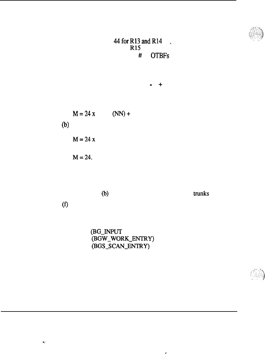
112 Memory calculations
Note
19 : Each DCHI consists of the following unprotected data blocks:
1. DCH U BLOCK = 43 words
44forR13andR14
_
47
for R15
2. Output request buffers = 5 x
#
of OTBFs
3. Output buffer = 261 words
4. Input buffer = 261 words
5. Unprotected call reference table = 2 + M
6. Unprotected message link table =
-
1 + M
M is computed as follows:
(a) If PRI 111 nn is defined for the DCH link:
M=24x
(max
@IN)+
1)
(b) If PRI 111 nn is not defined and the backup D-channel is defined
for the DCH link:
M=24x
2
(c) If PRI 111 nn and the backup D-channel are not defined:
M=24.
(d) If DCHI is in ISL mode:
M = maximum number of ISL trunks defined
(e) If DCHI is in SHARED mode:
M = (a) or
(b)
or (c) + maximum number of ISL trunks defined.
(f)
PR12 ONLY: unprotected data block of 65 words.
Note 20 : SIZE
(BG-lNPUT
AREA) (= 15)
+ SIZE
(BGW-WORK-ENTRY)
(= 26)
+ SIZE
(BGS.SCAN-ENTRY)
(= 25)
Total=66
Memory calculations 553-2201-151 Appendix 1
c.
I
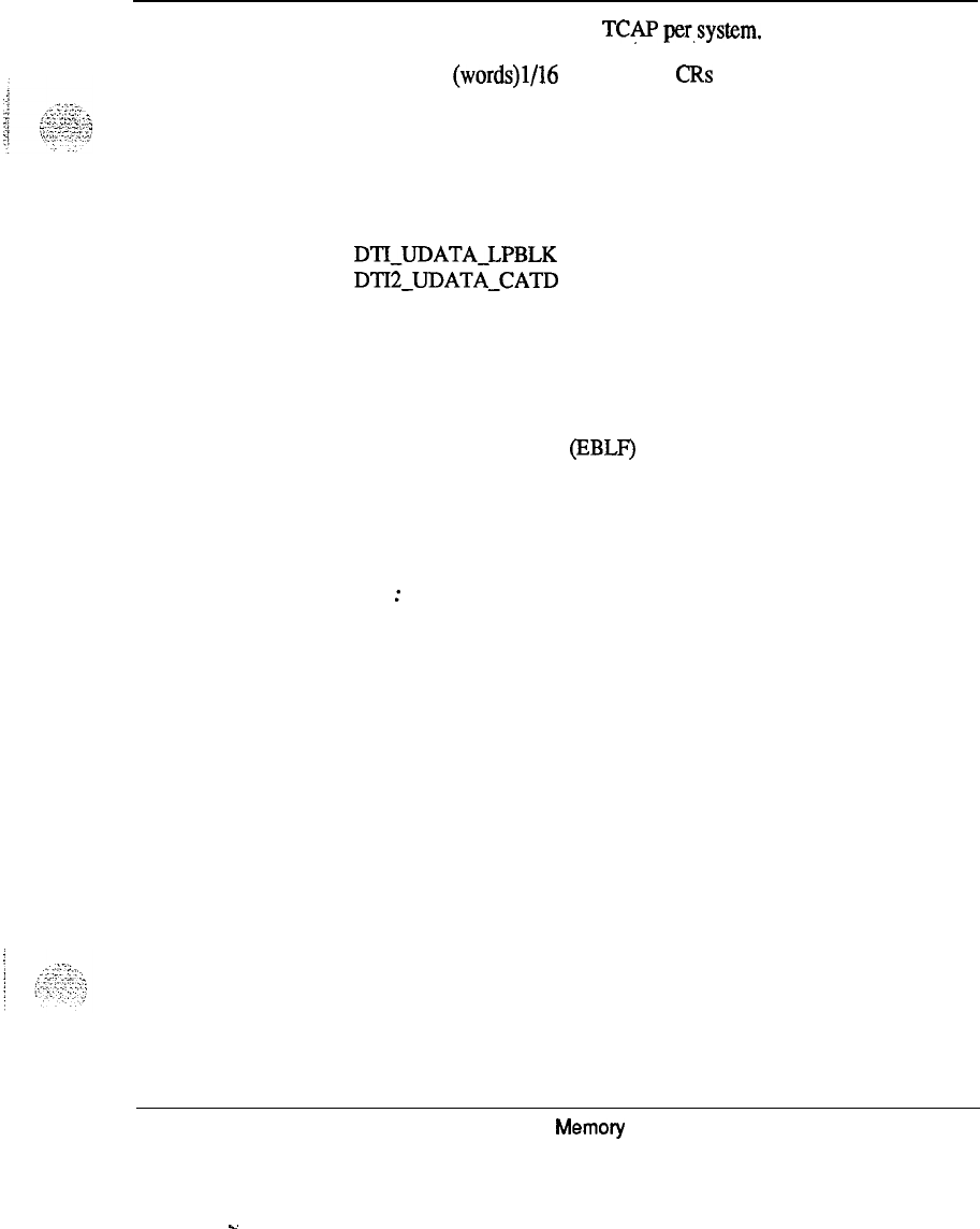
Memory calculations 113
Note 21:
One bit map table for TCAP per,system.
Size of bit map (words)1/16 x number of CBS defined per system
Traffic for TCAP4 words per Application ID (1)
Note
22 : Bach DTI loop requires the following:
DTI-UDATA-LPBLK
47
words
DTI2-UDATA-CATD
9 words
Note
23: Two words in the attendant unprotected data block per attendant
console is required. This is accounted for in the attendant data block size.
If Enhanced usy Lamp field (BBLF) is ON, a bit is required to indicate
idle/busy status of each DN. This equals 7 (16 bit) words per hundreds
group defined.
Note
24
:
Enhanced Ovefflow requires an additional 4 words per ACD DN.
Memory calculations 553-2201-l 51 Appendix 1
..d

114 Memory calculations
Memory calculations 553-2201-151 Appendix 1
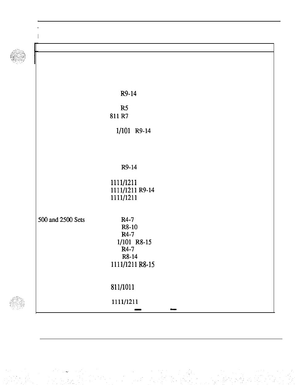
Table 5
Protected data storage requirements
Memory calculations 115
Feature Version Storage in Words Comments
Fixed amount of storage required for system operation.
711 R4 2981
711 R5 3077
711 R7 3253
711 R8 3249
711 R9-14 3250
811 R4 3109
811 R5 3148
811R7
3253
811 R8 3305
81 l/101 1 R9-14 3306
911 R4 3379
911 R5 3460
911 R7 3568
.
911 R8 3620
911 R9-14 3621
1011 R15 3461
1111/1211
R8
2981
1111/1211
R9-14 2982
1111/1211 R15 3092
5OOand25GOSets
For EACH of the following:
711 R4-7
711 R8-10
811 R4-7
81 l/101 1 RS-15
911 R4-7
911 R8-14
1111/1211
R8-15
(Note 1)
SL-1 Sets 711 (Note 2)
811/1011
911
1111/1211
-
continued
-
Memory calculations 553-2201-151 Appendix 1
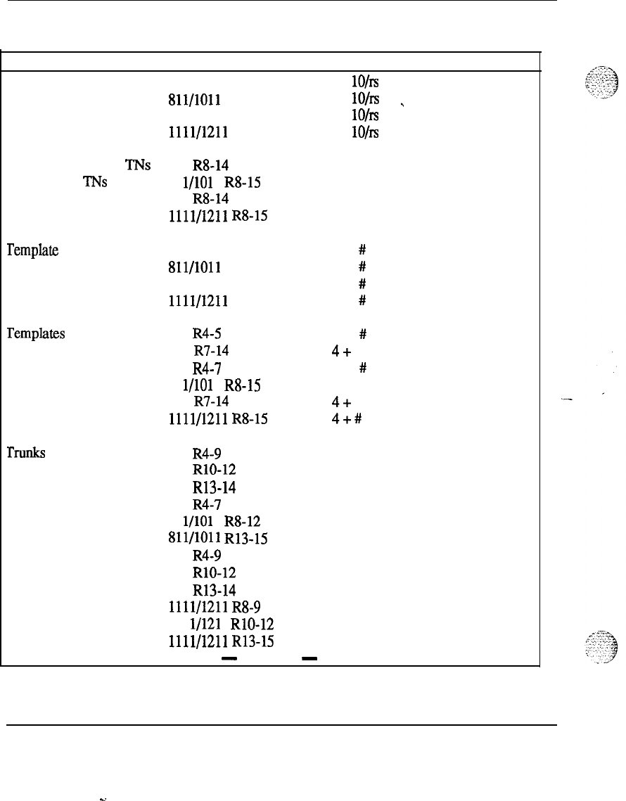
116 Memory calculations
Table 5
Protected data storage requirements (continued)
Feature Version Storage in Words Comments
Add-on K/L strips 711
lO/rs
811/1011 lO/rs
_
911
lO/rs
1111/1211
lO/rs
Data
Service Access TNs 711 R8-14 (Note 29)
VMS Access
TNs 81 l/101 1 R8-15
911 R8-14
1111/1211
R8-15
remplate Head Table
remplates
711 1 + # Templates
811/1011
1 + # Templates
911 1 + # Templates
1111/1211 1 + # Templates
711 R4-5
3
+ # Entries (Note 21)
711 R7-14
4+
# Entries
811 R4-7
4
+ # Entries
81 l/101 1 R8-15
4
+ # Entries
911 R7-14
4+
# Entries
1111/1211
R8-15
4+
#
Entries
rnlIlks 711 R4-9 10.5 (Note 22)
711 RlO-12 13.5
711 R13-14 16.5
811 R4-7 10.5
81 l/101 1 R8-12 13.5
811/1011
R13-15 16.5
911 R4-9 10.5
911 RlO-12 13.5
911 R13-14 16.5
1111/1211
R8-9 10.5
111 l/121 1 RlO-12 13.5
1111/1211
R13-15 16.5
-
continued
-
Memory calculations 553-2201-151 Appendix 1
s.
Table 5
Protected data storage requirements (continued)
Memory
calculations
117
Feature
Attendants
Version
711
811/1011
911
1111/1211
Storage in Words Comments
(Note 3)
Customers 711 R4
161
711 R5 166
711 R7
181
711 R8 203
711 R9 201
711 RlO 207
711 R12 211
811 R4
161
811 R5 166
811 R7
181
811 R8 203
811/1011
R9 201
Sll/lOll
RlO 207
81 l/1011 R12 211
911 R4
161
911 R5 166
911 R7
181
911 R8 203
911 R9 201
911 RlO 207
911 R12 211
1111/1211
R8
203
1111/1211
R9
201
111 l/121 1 RlO 207
1111/1211 R12 211
(Note 38 for)
Releases 13
through 15)
. .
1011 R15
1111/1211 R15
-
continued
-
46
46
Memory calculations 553-2201-151 Appendix 1
118
Memory calculations
Table 5
Protected data storage requirements (continued)
Feature
Trunk Routes
Version
711 R4
711 R5
711 R7-8
711 R9
711 RlO
711 R12
711 R13
811 R4
811 R5
811 R7-8
81 l/101 1 R9
81 l/1011 RlO
81 l/101 1 R12
81 l/1011 R13
911 R4
911 R5
911 R7-8
911 R9
911 RlO
911 R12
911 R13
1111/1211
R8
1111/1211
R9
1111/1211
RlO
1111/1211
R12
1111/1211 R13
Storage in Words Comments
31
#
of Routes
33 (Note 35 for
-
34 Release 14
35 through 15)
37
43
50
31
33
34
35
37
43
50
31
33
34
35
37
43
50
34
35
37
43
50
Code Restrictions 711
51
x#Code
81 l/101 1
51
Restriction
911 51 Routes
1111/1211
51
NFCR 711 (Note 17)
81 l/101 1
911
1111/1211
-continued
-
Memory calculations 553-2201-l 51 Appendix 1
Memory calculations 119
Table 5
Protected data storage requirements (continued)
Feature
Peripheral Signaling
Version Storage in Words Comments
711 30
1
item
811/1011 30
911 30
1111/1211 30
Vetwork Group 711 16
811 R4-7 32
81 l/101 1 R8-15 32
911 38
1111/1211 38
Vetwork-LOC 711 R4-5 68
711 R7-14 70
811 R4-5 68
. .
811 R7 70
811/1011
R14-15 70
911 R4-5 68
911 R7-14 70
1111/1211 70
Vetwork-RPE 711 R4-5
71
711 R7-14 73
811 R4-5
71
811 R7 73
81 l/1011 R8-15 73
911 R4-5 71
911 R7-14 73
1111/1211 73
TDS 711 2
811/1011 2
911
2
1111/1211 2
-
continued
-
Memory calculations 553-2201-151 Appendix 1
. .

120 Memory calculations
Table 5
Protected data storage requirements (continued)
Feature
MF Sender
Conference
Digitone
Receiver
Version
711
811/1011
911
1111/1211
711
811/1011
911
1111/1211
711
811/1011
911
1111/1211
Storage in Words Comments
2
2
_
2
2
2
2
2
2
8
8
8
8
DN Translator
711
(Note 4)
811/1011
911
1111/1211
DIG Translator
711
(Note 5)
811/1011
911
1111/1211
SCL Master Head Table
for
SCL
Head Table
711
1 + Number of Lists 1 item
811/1011
1
+
Number
ofLists (Note 39 for
911
1
+
Number
ofLists Releases 13
1111/1211 1 + Number of Lists
through 15)
711
1 list
per
81 l/101 1 (Note 15)
911
1111/1211
-
continued
-
Memory calculations 553-2201-151 Appendix 1
Memory calculations 121
Table 5
Protected data storage requirements (continued)
---:...
.i
.
.
.
. ,,, ,.
^
,...
-:
.
,
,_
_:
Feature Version
711
81
l/101
1
911
1111/1211
Storage in Words Comments
# SC Lists
(Note 6)
3ASMain
711
811/1011
911
1111/1211
# Customers
3ASPemote
711
15
811/1011
15
911
15
1111/1211
15
#
Customers
. .
BARS 711
811/1011
911
1111/1211
# Customers
(Note 7)
FTC 711
811/1011
911
1111/1211
32 Tables
(Note 42)
EFTC
7111
811/1011
911
1111/1211
32 Tables
(Note 44)
NARS
711
# Customers
81
l/101
1 (Note 8)
911
1111/1211
-
continued
-
Memory calculations 553-2201-l 51 Appendix 1
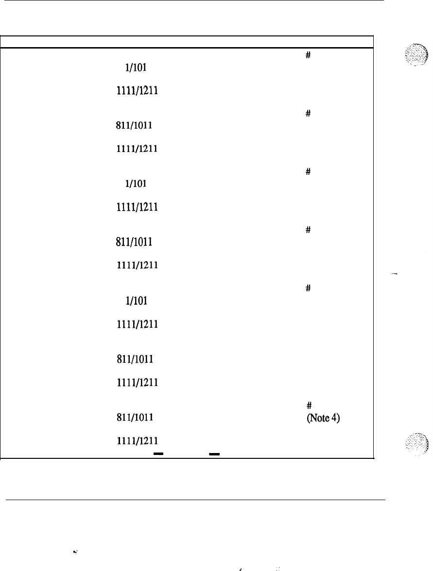
122 Memory calculations
Table5
Protected data storage requirements(continued)
Feature Version Storage in Words Comments
CDP 711 #
Customers
81 l/101 1 (Note.9)
911
1111/1211
ACD 711
811/1011
911
1111/1211
#
Customers
(Note 10)
Group DND 711
81 l/101 1
911
1111/1211
#
Customers
(Note 11)
DISA 711
811/1011
911
1111/1211
#
Customers
(Note 12)
AUTH
711
81 l/101 1
911
1111/1211
#
Customers
(Note 13)
HIST 711
811/1011
911
1111/1211
1 item
(Note 14)
CPRK
711 #
Customers
811/1011 (Note4)
911
1111/1211
-
continued
-
Memory calculations 553-2201-l 51 Appendix 1
-.
,
:
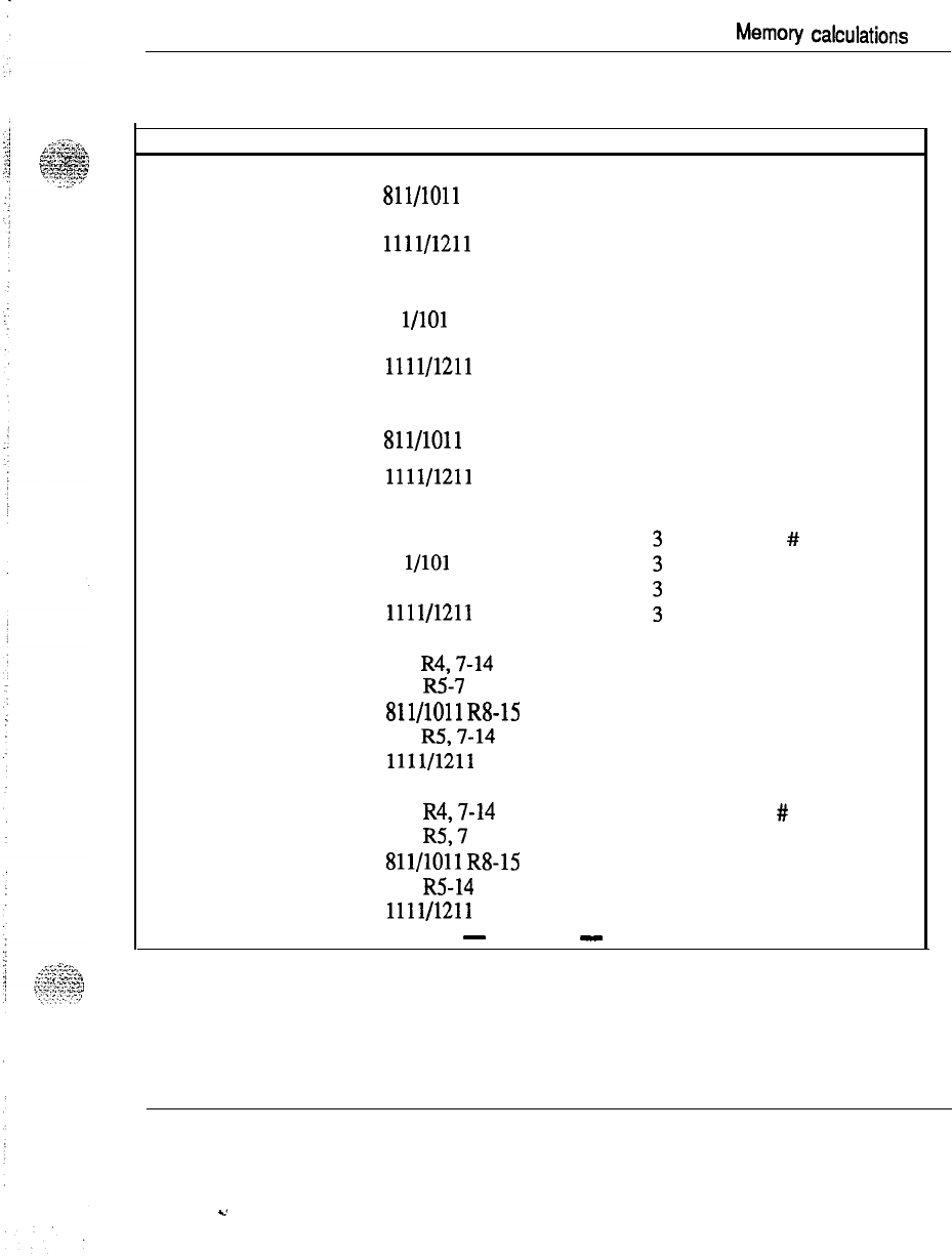
Memory
cakulations
123
Table 5
Protected data storage requirements (continued)
IMS
Feature Version
711
811/1011
911
1111/1211
Storage in Words Comments
370
1 list
per
370 (Note 16)
370
370
NFCR 711
81 l/101 1
911
1111/1211
1 customer
per
(Note 17)
Soft Memory 711
811/1011
911
1111/1211
35
35
35
35
1 item
TDET 711 #
TDET
81 l/101 1
911
1111/1211
DTI
711
R4,7-14
811 R5-7
811/1011
R8-15
911
R5,7-14
1111/1211
1 item
(Note 18)
AMP
711
R4,7-14
811
R5,7
811/1011
R8-15
911
R5-14
1111/1211
-
continued
-
# Modem Pools
(Note 19)
Memory calculations 553-2201-151 Appendix 1
.,
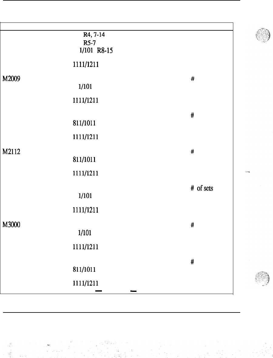
124 Memory calculations
Table 5
Protected data storage requirements (continued)
Feature
Multiple Office Code
Screening
Version
711 R4,7-14
811
R5-7
81
l/101
1
R8-15
911
1111/1211
Storage in Words Comments
1 per location code (if
defined)
(Note 20)
M2009
Telephone
711
81 l/101 1
911
1111/1211
# telephones
(Note 23)
M2018 Telephone 711
811/1011
911
1111/1211
#
telephones
(Note 25)
M2112
Telephone
711
811/1011
911
1111/1211
#
telephones
(Note 24)
M23 17 Digital Set 711 #
ofsets
81 l/101 1 (Note 3 1)
911
1111/1211
M3000
Touchphone
711
81 l/101 1
911
1111/1211
#
telephones
(Note 26)
Multi-Tenant 711 #
of Customers
811/1011 (Note 27)
911
1111/1211
-
continued
-
Memory calculations 553-2201-l 51 Appendix 1
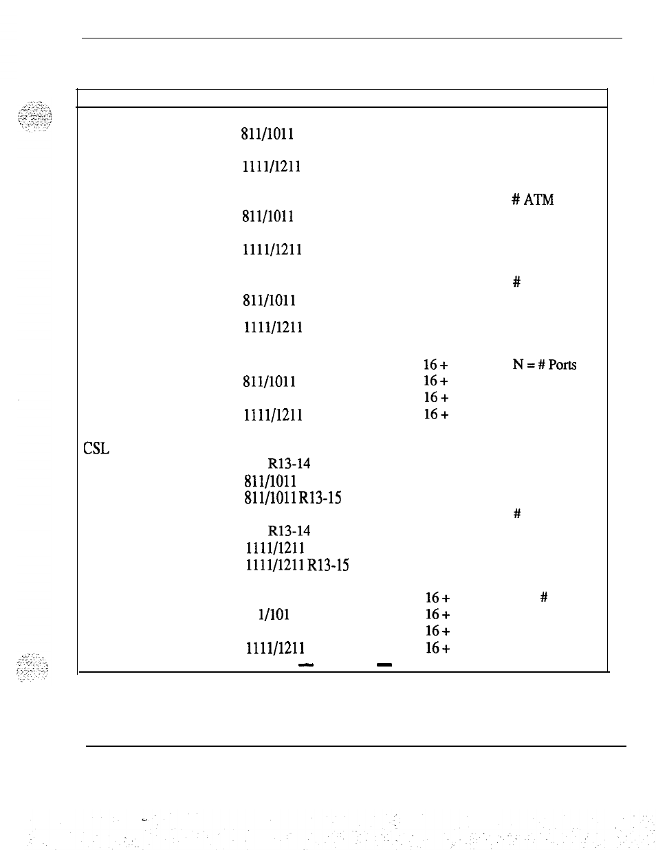
Memory calculations 125
Table 5
Protected data storage requirements (continued)
Feature
ATM Schedule Block
Version
711
811/1011
911
1111/1211
Storage in Words Comments
(Note 28)
ATM Data Block 711
12
#
ATh4
Routes
811/1011 12
911 12
1111/1211
12
DLI 711
811/1011
911
1111/1211
#
DLI Loops
(Note 18)
. .
ESDI 711
16+
Nx
7
N=#Ports
811/1011
16+
Nx
7
911
16+
Nx
7
1111/1211
16+
Nx
7
CSL 711 2 # Links
711 R13-14 4
811/1011 2
811/1011
R13-15 4
911 2 # Links
911 R13-14 4# Links
1111/1211 2# Links
1111/1211
R13-15 4# Links
VAS
711
16+
N
N = # Servers
81 l/101 1
16+
N
911
16+
N
1111/1211
16+
N
-
continued
-
Memory calculations 553-2201-151 Appendix 1
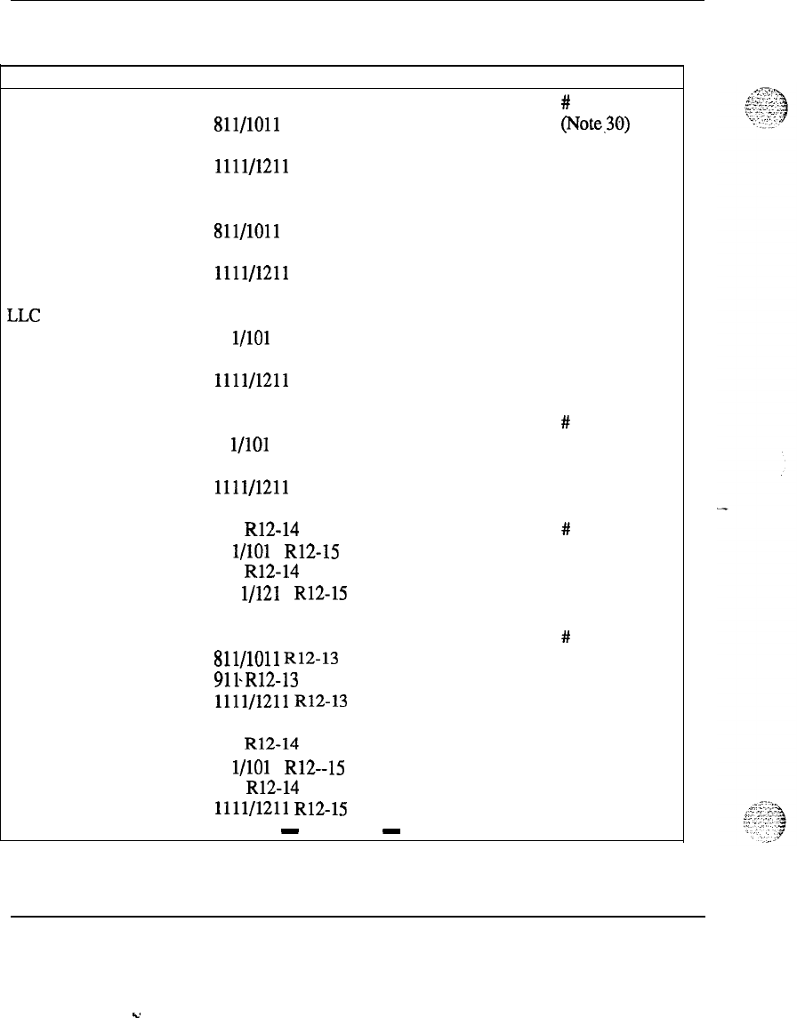
126 Memory calculations
Table 5
Protected data storage requirements (continued)
Feature
VAS DSDN
Version
711
811/1011
911
1111/1211
Storage in Words Comments
# Customers
(Note.30)
CPND 711
811/1011
911
1111/1211
Per system
(Note 32)
LLC 711 5
81 l/101 1 5
911 5
1111/1211 5
Auxiliary
Customer 711 187
81 l/101 1 187
911 187
1111/1211 187
# Customers
ISDN PRA 711 R12-14
81 l/101 1 R12-15
911 R12-14
111 l/121 1 R12-15
#
PRI
(Note 33)
ISDN PRA
(Note 34) 711 R12 #
DCHI
811/1011
R12-13
911.R12-13
1111/1211
R12-13
ISDN PRA 711 R12-14 SID tables
81 l/101 1 R12--15 (Note 36)
911 R12-14
1111/1211
R12-15
-
continued
-
Memory calculations 553-2201-l 51 Appendix 1
s.
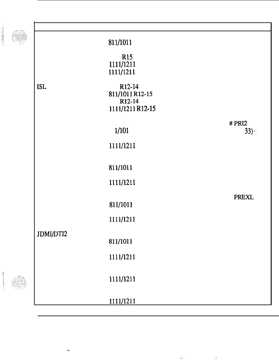
Memory calculations 127
Table 5
Protected data storage requirements (continued)
Feature
AWU Count
Version Storage in Words
711 144
811/1011
144
911 144
1011 R15
288
1111/1211
144
1111/1211 R15
288
Comments
ISL 711 R12-14
811/1011
R12-15
911 R12-14
1111/1211
R12-15
#DCHI
(Note 37)
ISDN PR12 711
81 l/101 1
911
1111/1211
#PRI2
(Note 33)s.
ISDN PR12 711
811/1011
911
1111/1211
# DCHI
(Note 34)
Pretranslation 711
811/1011
911
1111/1211
#
PREXL
(Note 40)
JDMI/DTI2 711
811/1011
911
1111/1211
(Note
4 1)
EBLF
1011
1111/1211 (Note 44)
EOVF 1011 R15 (Note 45)
1111/1211
R15
Memory calculations 553-2201-151 Appendix 1
.
.
:..
. .
.,:
. .
128 Memory calculations
No&
I
:
The size of the protected line block for
PBX
telephones is
determined from the following:
Basic Line Block
4 words Release 4
5 words Releases 5 through 9
6 words in Release
JO
Basic
Line Block
(ODAS)
Card Block Component
7 words in Releases 12 through 15
7 words Releases 4 and 5
8 words Releases 7 through 12
10 words Releases 13 through 15
1.5 words
The key layout portion of the template requires (2 + nf)/rs words in Release
4 or, (4 + nf)/rs words in Releases 5 through 15, where “nf’ is the number
of features defined for the telephone, and “rs” is the number of telephones
sharing the same template.
-
Memory calculations 553-2201-l 51 Appendix 1

Memory calculations 129
In addition to the basic line block, each feature requires extra data space as
follows:
Feature
FM-5
R7-12 R13 R14-15
Associate Set
-
2
words
2
words
2
words
Automatic Wake-Up
1 word 1 word 1 word
Call Forward Key
(4-24 digits)
l-6 words
l-6
words l-6 words
Call Forward by Call
2
words
2
words
2
words
Type
Call Party Name
Display
CFNAIHunting
Key
Dial Intercom Key
DN Key
EFD/EHT DN
Hot Line DN
(l-31 digits)
. .
1 word + 3 to 13
1
word+4to14
1
word+4to14
words words words
(6-26 characters, 2
(6-26 characters, (6-26 characters,
characters per 2 characters per 2 characters per
word) word) word)
-_
1 word 1 word
2
words
2
words
1 word 1 word 1 word
1 word 1 word
2
words
2
words
-
1 word (R12)
2
words
2
words
-
l-8 words
2-l 0 words 2-l 0 words
-
continued
-
Memory calculations 553-2201-151 Appendix 1
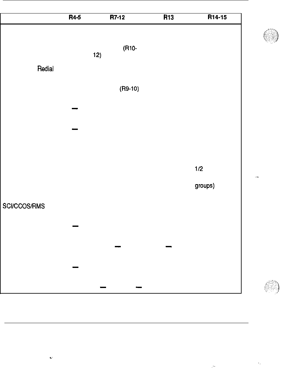
130 Memory calculations
Feature
Enhanced Hot Line
(l-31 digits)
Last Number Redial
(3-32 digits)
(4-32 digits)
Manual Line
Message Center DN
Message
Registration
Pretranslation
Enhancement
R46
R7-12 R13 R14-15
2-l 0 words
(Rl
O-
2-10 words .
2-10 words
12)
1 word (R8) 1 word
l-8 words
(R9-10)
l-8 words l-8 words
-
1 word
2
words
2
words
-
1 word
2
words
2
words
1 word 1 word 1 word
l/2
word
(for 255 calling
grows)
SCI/CCOS/RMS
1 word 1 word 1 word
Speed Call Controller
-
1 word 1 word 1 word
Speed Call Key 1 word
-
-
Speed Call User
-
1 word 1 word 1 word
-
continued
-
Memory calculations 553-2201-151 Appendix 1
s.
‘.
:.
Memory calculations 131
Feature
Stored Number
Redial
(4-32 digits)
System Speed Call
User
I
Tenant Number
R46
R7-12 R13 R14-15
l-8 words l-8 words l-8
wqrds 1-b words
-
1 word 1 word 1 word
-
1 word 1 word 1 word
Note 2 : The size of the protected line block for SL-1 telephones is
determined from the following:
Basic Line Block
7 words in Release 4
‘-
8 words in Release 5
9 words in Release 7
10 words in Releases 8-13
13 words in Release 14-15
Basic Line Block (ODAS)
10
words Releases 4 and 5
--
12
words Releases 7-12
16
words Releases.13 -15
Card Block Component 1.5 words
The key layout portion of the template in Release 4 requires 12/rs words,
where rs = the number of telephones sharing the same template.
The key layout portion of the template, in Releases 5 through 15, requires (4
+ the number of key lamp strips x 10)/m words, where rs = the number of
telephones sharing the same template.
Memory calculations 553-2201-151 Appendix 1
132 Memory calculations
In addition to the basic
line
block requirement, each feahue requires extra
data space as follows:
Feature R4-5 R7-12 R13 R14-15
ACD Agent Key
1 word 1 word 1 word
-
1 word
ACD Display Queue Key 1 word 1 word
2
words
2
words
ACD
Interflow
Key
1 word
1 word
2
words
2
words
ACD IN-CALLS key
9 words 11 words 11 words 11 words
ACD Night Service DN
2
words
2
words
Autodial
Key l-8 words
(4-32 digits)
Autodial
Key
(4-24 digits)
l-6 words l-6 words
l-6
words
Automatic Wake-Up
Call Forward Key
(4-24 digits)
1 word
(RlO-
1 word
12)
l-6 words l-6 words l-6 words
1 word
l-6 words
Call Forward by Call
2
words
Type
(Rl
o-1 2)
2
words
2
words
-
continued
-
Memory calculations 553-2201-151 Appendix 1
-
:
..z:...
j
;.
.,._.
\
,y,
I?
;.
-:-:
-:
:.:‘-;:
,:.
‘,’
Memory calculations 133
Feature
CFNA DN
R46
1 word
R7-12
1 word
R13
2
words
R14-15
2
words
Conference Autodial
l-6
words
Conference Hotline 3-l 0 words
Conference Speed Call
DIG Key
DN Key
EFD/EHT DN
1 word
1 word
.’
word
word
1 word
1
word 1 word
2
words
2
words I.
Flash Call Key 1 word
Flash Override Call Key
1 word
Hot Line
(1-31 digits)
word
word
word
2
words
2
words
1
word 1 word
1
word 1 word
3-l 0 words
Hot Line, Enhanced
Hunt DN
2-l 0 words 2-l 0 words
(Rl
o-1 2)
1
word
1
word
2
words
2
words
Immediate Call Key 1 word 1 word 1 word 1 word
-
continued
-
Memory calculations 553-2201-151 Appendix 1
134 Memory calculations
Feature
Last Number Redial
(4-32 digits)
Message Center DN
Message Registration
Park Key
Pretranslation
Enhancement
Priority Call Key
Private Line Key
m-5
R7-12 R13 R14-15
1 word (R8) 1 word
l-8 words
l-8 words
(R9-12)
1 word 2words 2words
1 word (RlO)
1
word
1
word
1
word 1 word
1
word
1
word
l/2
word (for 255
calling groups)
1
word 1 word
1
word
1
word
1 word 2words 2words
SCI/CCOS/RMS
(131 digits)
Signal Key
Speed Call Controller
Speed Call Key
1
word
1 word
1 word
(RlO-
1
word
14
1 word 2words 2words
1 word
1
word
1
word
-
continued
-
Memory calculations 553-2201-l 51 Appendix 1
Memory calculations
135
I
Feature
R45
R7-12 R13 R14-15
Speed Call User
Stored Number Redial
Key
1
word
1
word
1
word
(4-32 digits)
Tenant Number
Time and Date Key
Voice Call Key
l-8 words l-8 words
1-8
words
l-8 words
1
word
1
word
1
word
1
word
1
word
1
word
1
word
1
word
2
words
2
words
._
Note 3 : The size of the protected line block for attendant telephones is
determined from the following:
Card Block Component 3 words
Primary Line Block
Secondary Line Block
14 words in Release 4
15
words in Releases 5 through 12
21
words in Releases 13 and 14
24 words in Release 15
4 words
3 words in Release 15
Memory calculations 553-2201-l 51 Appendix 1
136 Memory calculations
In addition to the basic linebloclc, each fea@re requires extra data space as
follows:
Feature Requirements
Autodial Key
8
words
6
words in Releases 7-15)
Flash Call Key 1 word (R8-12)
Flash Override Call Key 1 word
Group DND Key 1 word
Immediate Call Key 1 word
Paging Key 1 word
2
words in Releases 13-l 5
Priority Call Key 1 word
Speed Call Key 1 word
Store Number Redial Key
8
words
,
-2
.
.
.
4
‘.:
,j
*
Memory calculations 553-2201-151 Appendix 1
-.
:I
.,
_.
:...:
_
-j
::;;:..i.::..
;
..;
:,,,
.‘;
Memory calculations 137
Note 4 :
Prior to
Rekase
13, the memory requirements for the
D&tory
Number Translator are (in words of protected data store):
(2xS)+AS+12x(l+
Nl+N2+N3)
+ADx(~+AIx~)+(DDx~)+SPDN
+ number of listed DN
+ 1 per defined DN
+ 16 (+ 64
withReleases
8and9)
(+ 65
with Release 10)
(+ 66 with Release 12)
if any attendants are defined
+ 1 if special service prefix defined
+ 3
per
NARSBARS
access code defined
+ 7
if RSANI access code defined
+ 1 if CAS Hold DN is defined
+ 2
if CAS RLT DN is defined
+ 3
per CDP steering code defined
+ 2 per defined Test Line DN
+ 1 per defined ACD-DN
+ 1 per defined DIG Group
+lperSLlDN
Releases 13 through 15:
(2xS)+AS+12x(l+Nl+N2+
N3+
N4+
N5+
N6)
+ADx(2+
AIx2)+
(DDx2)+
SPDN
+ number of listed DNs
+ 2
per defined DN
+ 16 (+ 66)
if any attendants are defined
+ 1 if special service prefix defined
+ 3
per NARS/BARS access code defined
+ 10 if RSANI access code defined
+ 2 if CAS Hold DN is defined
+ 2
if CAS RLT DN is defined
+ 3
per CDP steering code defined
+ 2 per defined Test Line DN
+ 1 per defined ACD-DN
+ 1 per defined DIG Group
+lperSLlDN
Memory calculations
.d
553-2201-l 51 Appendix 1

138
Memory
calculations
where:
S = number of different DN appearing on SL- 1 telephones, 500/2500
telephones mixed with SL- 1 telephones, and private line 500/2500
telephones
-
AS = number of appearance of DN within S
Nl
= number of different first digit in the numbering plan
N2 = number of different sequence of the
fast
two digits in the
numbering plan (if DN is more than 2 digits)
N3 = number of different sequence of the first three digits in the
numbering plan (if DN is more than 3 digits)
N4 = number of different sequence of the first four digits in the
numbering plan (if DN is more than 4 digits)
N5 = number of different sequence of the first five digits in the
numbering plan (if DN is more than 5 digits)
N6 = number of different sequence of the first six digits in the
numbering plan (if DN is more than 6 digits)
AD = number of ACD-DNs
_
AI = number of ACD POSITION-ID
S
in each ACD-DN
DD = number of DISA-DNs
SPDN = number of System Park DNs
Memory calculations 553-2201-151 Appendix 1
Memory calculations 139
Note
5
: The protected data store requirements for the Dial Intercom feature
for each customer using the package are as follows:
l+
Gx
(l+
2x M)
where:
G = number of groups
M = number of members in each group
Release 14 through 15:
(n
+
1)
+
(x
x
(2
+
(~~21)
1
where:
n = maximum number of dial intercom groups in Overlay 15
x = actual number of dial intercom groups configures
y = average number of members in each dial intercom group
Note 6 : The size of a Speed Call List is:
((NB -1) x 256) + (NBR x WE)
where:
NB and WE is calculated as described in Note 15 under the Speed
CalList
Head Table
NBR is the remainder of the calculation to determine NB, which was
NB =
EL/EB
When
EL/EB
is zero, use the following formula:
((NB-l)x256)+(EBxWE)
The following quick reference chart facilitate the programming of the Speed
Call List memory requirements. Locate the intersect point of the required
DN and list sizes to determine the number of words needed.
Memory calculations 553-2201-151 Appendix 1
-.
.:

140 Memory
calculations
Speed Call Quick Reference Chart
List Size
DN Size
4 8 12 16 20 24 28
31
1
6
7
8
9
10 Ii
12
13
5
10
15 20 25 30 35 40 45
10 15
25 35 45 55 65 75 85
20 25 45 65 85 105 125 145 165
25 30 55 80 105 130 155 180 205
30 35 65 95 125 155 185 215 245
40 45 85 125 165 205 245 290 326
50 55 105 155 205 255 310 360 406
60 65 125 185 245 312 370 340 486
I.
70 75 145 215 290 362 430 500 568
75 80 155 230 310 402 460 538 608
80 85 165 245 330 442 490 576 648
90 95 185 280 370 462 556 646 728
100 105 205 310 410 512 616 716 808
200 205 412 615 820 1026 1226
1431
1612
250 255
511
765 1020 1284
1531
1787 2013
300 312 619 920 1226
1541 1841
2147 2416
,
400 412 826 1226 1636 2055 2542 2863 3220
500 512 1026
1531
2041 2570 3063 3573 4023
600 619 1234 1853 2708 3085 3678 4289 4827
700 719
1441
2147 2862 3599 4289 5004 5631
750 769
1541
2297 3062 3856 4594 5359 6033
800 826 1648 2452 3268 4113 4904 5720 6435
900 926 1855 2667 3678 4628 5515 6431 7240
1000 1018 1955 3050 4083 5142 6125 7146 8043
Memory calculations
553-2201-151 Appendix 1
s.
:
.
.
Memory calculations 141
Note 7 : The protected data store requirements for BARS (on a per-
customer basis) are:
Release 4
137
+ 2.73 x (HNPA + NPA) + 2.73 x
(1HNF’A
+
1NF’A)
+
RLx(8+
3xRLE)+
DMEx(3+
I/4)+ FCAS
Releases 5 and 7
137 + 2.73 x (HNF’A + NPA) + 2.73 x (1HNF’A + INPA)
+
RLx(8+
3x:RLE)+
DMEx(3+
I/4)
+ FCAS+
SDRRx(3+
2xSDE)+
ITGE
Releases 8through 12
16
+ SUM+
RLx(8+
3xRLE)+
DMEx(3+
I/4)
._
+ FCAS+
SDRRx(3+
2xSDE)+
ITGE
Releases 13 and 14
BASICESN
+SUM+RLx(8+3xRLE)+DMEx(3+1/4)
+ FCAS + SDRR x (3 + 2 x SDE) + ITGE
Release 15
BASICESN
+SUM+RLx(8+3xRLE)+DMEx(4+1/4)
+ FCAS + SDRR x (3 + 2 x SDE) + ITGE
where:
SUM=
[(lOxR)xxn]-1
11 x words
(lOxR)-1
j
:..:‘,:‘.
L..”
1
:-,
:<.
.::-::,
!
“+-‘.v:;
n=
HNPA =
maximum level of tree (n > 0)
number of NXX in the home NPA of the
SL-1
Memory calculations 553-2201-151 Appendix 1
142 Memory calculations
I=
NPA=
lHNPA=
1NPA =
R=
RL=
RLE=
DME=
FCAS =
where:
SDRR =
SDE =
ITGE =
the average number .of digits that must be
inserted as part of digit manipulation
number of NPA (area codes) in the North
American dialing plan
number of 1 + NXX in the home NPA of the SL-1
number of 1 + NPA (area codes) in the North
American dialing plan
the rate of digits equipped in each level of the tree
(translator)
the number of route lists
he average number of route lists entries per
route list
.
the number of distinct digit manipulation entries
(included the default 0th entry)
(N
+ 1) + N(M + 1) +
MN[
4 +
(1OOP
+
15)/16]
N = the number of defined FCAS tables
M = the average number of NPA codes per table
P = the average number of first digit of NXX codes
Number of supplemental digit
restricted/recognized blocks defined for NPA,
NXX, LGC, SPN
Average number of SDRR entries for each SDRR
block
9 x ITEI; where ITEI = the number of
Incoming Trunk Group Exclusion Index
BASICESN =
SIZE
(ESN-DATA-BLoCK)+SIZE
(NCTI-DATA-BLOCK
Memory calculations 553-2201-l 51 Appendix 1
.
.
Memory calculations 143
129 + 305 = 434
SIZE
(ESNJ’RAN-BLOCK)
= 1
I
This formula is based on the assumption that the IWA/NXX translation tree
is half full and distributed evenly. This should represent the typical case.
For more precise calculation, use NABS formula.
.
Note 8 : The protected data store requirements for NABS (on a per-
customer basis)are:
Release 4
137 +
12x(1+
Al+
A2)+
12x(A3+
A4)
+
12x(1+
Bl+
B2)+
12x(l33+
B4)
+
4xRN+
RLx(8+
3xRLE)+
DME
x(3+
I/4)+
LOCx6+
FCAS+ SCC
Releases 5 and 7
137 +
11x(1+
Al+
A2)+
llx(A3+
A4)
+
11x(1+
Bl+
B2)+
llx(B3+
B4)
+SDRRx(3+2xSDE)+RLx(8+3xRLE)+DME
x (3 + I/4) + LGC x 6 + FCAS + SCC + ITGE + MDID
Releases 8 through 12
16 +
SUMl+
SUM2
+SDRRx(3+2xSDE)+RLx(8+3xRLE)+DME
x(~+I/~)+LGCX~+FCAS+SCC+ITGE+MDID
Releases 13 and 14
BASICESN
+ SUM1 + SUM2
+SDRRx(3+2xSDE)+BLx(8+3xRLE)+DME
x (3 + I/4) + LGC x 6 + FCAS + SCC + ITGE + MDID
Release 15
BASICESN
+ SUM1 + SUM2
+SDRRx(3+2xSDE)+BLx(8+3xRLE)+DME
x(~+I/~)+LGCX~+FCAS+
SCC+ITGE+MDID
Memory calculations 553-2201-l 51 Appendix 1
.

144
Memory calculations
where:
SuIvll
=
suM2=
SUM=
II=
Al=
A2=
A3=
A4=
Bl
=
number of different first digit in network translator 2.
B2=
number of different sequence of the first two digits in the
non
l+
number in network translator 2.
B3 =
B4=
R=
RL=
RLE=
DME=
(SUM of network translator 1)
(SUM of network translator 2)
[(lOxR)xxn]
-1
11
x
____________________________
wor&
(lOxR)-
1
maximum level of tree (n > 0).
number of different first digit in network translator 1.
number of different sequence of the
fist
two digits in the
non
l+
number in network translator 1.
number of different second digits in the
l+
number in network translator 1.
number of different sequence of the second and third digits
in the
l+
number in network translator 1.
number of different second digits in the
l+
number in network translator 2.
number of different sequence of the second and third digits
in the
l+
number in network translator 2.
is the rate of digits equipped in each level of the tree
(translator).
the number of route lists.
the average number of route lists entries per route fist.
the number of distinct digit manipulation entries (included
the default 0th entry).
Memory calculations 553-2201-151 Appendix 1
Memory calculations 145
I=
the average number. of digits that must be
inserted as part of digit manipulation.
LGC=
number of on-net or virtual locations.
FCAS = (N + 1) + N(M + 1) + MN[ 4 +
(1OOP
+ 15j/16]
where:
N = the number of defined FCAS tables
M = the average number of NPA codes per table
P = the average number of first digit of NXX codes
see
=
Number of entries in the SCC table.
SDRR =Number of supplemental digit restricted/recognized blocks
defined for NPA, NXX, LGC, SPN.
SDE = Average number of SDRR entries for each SDRR block.
. .
ITGE = 9 x ITEk where ITEI = the number of Incoming Trunk
Group Exclusion Index.
MDID =(2 x number of total office codes) + (2 x number of total
DID ranges regardless of which office codes they belong
to). Maximum of 20 ranges or office codes can be defmed
per location code, (i.e., 1 office code and 20 ranges, or 20
office codes and 1 range for each office code).
BASICESN =
SIZE(ESN-DATA-BLOCK)
+
SIZE(NCTI-DATA-BLOCK)
129 +
305 = 434
. .
Memory calculations 553-2201-151 Appendix 1
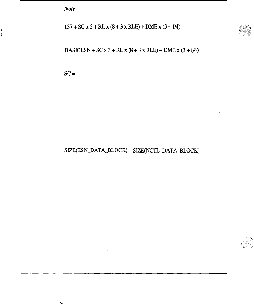
146 Memory calculations
Note 9 : Prior to Release 13, the protected data store requirements for CDP
(on a per-customer basis) are:
137+SCx2+RLx(8+3xRLE)+DMEx(3+1/4)
Releases 13 through 15
where:
SC=
number of steering codes
RL=
the number of route lists
RLE=
the average number of route lists entries per route
list
DME=
the number of distinct digit manipulation entries
..
I=
the average number of digits that must be
inserted as part of digit manipulation.
BASICESN =
SIZE(ESN-DATA-BLOCK)
+
SIZE(NCTL-DATA-BLOCK)
129 +
305 = 434
CDP Steering Codes also occupy SL- 1 DN tree spaces. This portion of data
store is calculated in DN tree formula (See Note 4).
Memory calculations 553-2201-151 Appendix 1
L.
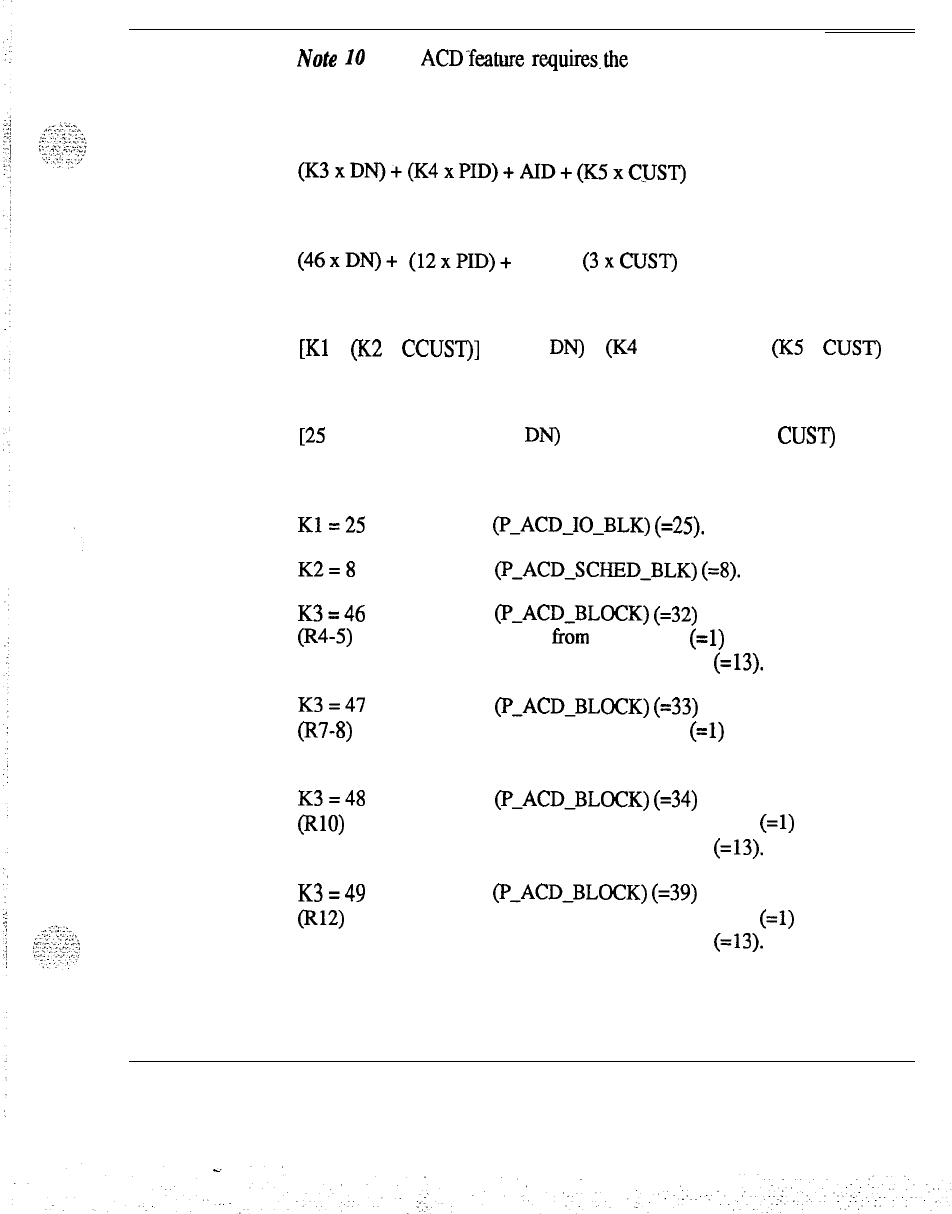
Memory calculations 147
Note 10 : The ACD-feature requires.the following additional data store
(total for system):
For ACD-C not equipped
(K~xDN)+(K~xPID)+AID+(K~xCUST)
.
Simplified
(46xDN)+
(12xPID)+
AID+
(3xCUST)
For ACD-C equipped
[Kl
+ (K2 x CCUST)] + (K3 x DN) + (K4 x PID) + AID + (K5 x CUST)
Simplified
[25 + (8 x CCUST)] + (46 x DN) + (12 x PID) + AID + (3 x CUST)
where the multiplication constants (Ki) are:
K1=25
K2=8
K3=46
@4-5)
size
(I-ACD-IO-BLK)
(=25).
size
(P-ACD-SCHEDBLK)
(=8).
size
(P-ACDBLOCK)
(=32)
+ ptr to blk from ACD LIST
(=l)
+ word offset (ACD-POS-TN) (=13).
K3=47
(R7-8)
size
(P-ACD-BLOCK)
(=33)
+ ptr to blk from ACD LIST
(=l)
+ word offset (ACD-POS-TN) (= 13).
K3=48
(Rw
size
(l-ACD-BLOCK)
(=34)
+ pointer to block from the ACD List
(=l)
+ word offset (ACDPOS-TN) (=13).
K3=49
(Rw
size
(P-ACD-BLOCK)
(=39)
+ pointer to block from the ACD List
(=l)
+ word offset (ACD-POS-TN) (=13).
Memory calculations 553-2201-l 51 Appendix 1
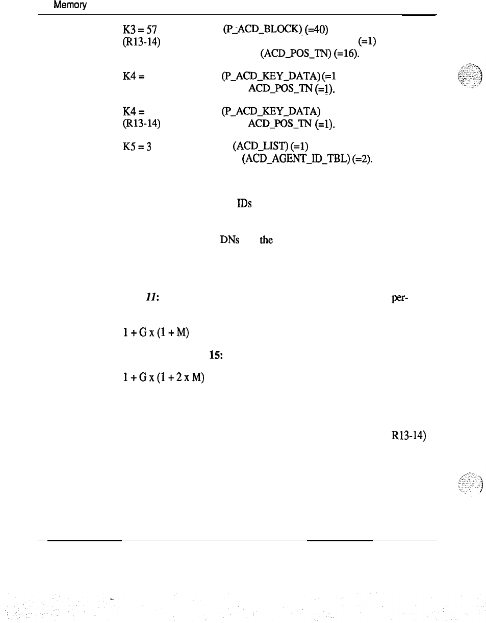
148
Memoty
calculations
K3=57
(R13-14)
size
(PLACD-BLOCK),
(40)
+ pointer to block from the ACD List
(=l)
+ word offset (ACD-PQS-TN) (=16).
K4=
12 size
(I-ACD-KEY-DATA)
(=l
1)
+ store for
ACD-POS-TN
(=l).
K4=
14
(Rl3-14)
K5=3
size
(P-ACD-KEY-DATA)
(= 13)
+ store for ACD-POS-TN
(=l).
header (ACD-LIST)
(=l)
+ header
(ACD-AGENT-ID-TBL)
(=2).
and the variables are represented by:
AID = total no. of AGENT
IDS
(for the system)
CCUST = total no. of customers with ACD-C package
CUST = total no. of customers with ACD-C/D packages
DN = total no. of ACD DNs (for the system)
PID = total no. of AGENT POSITION
S
(for the system).
Note
II:
The protected store requirements for Group DND (on a per-
customer basis) are:
l+Gx(l+M)
Release 13 through 15:
l+Gx(l+2xM)
where:
G = number of groups
M = number of members in each group (2 words per member for R13-14)
Memory calculations 553-2201-151 Appendix 1
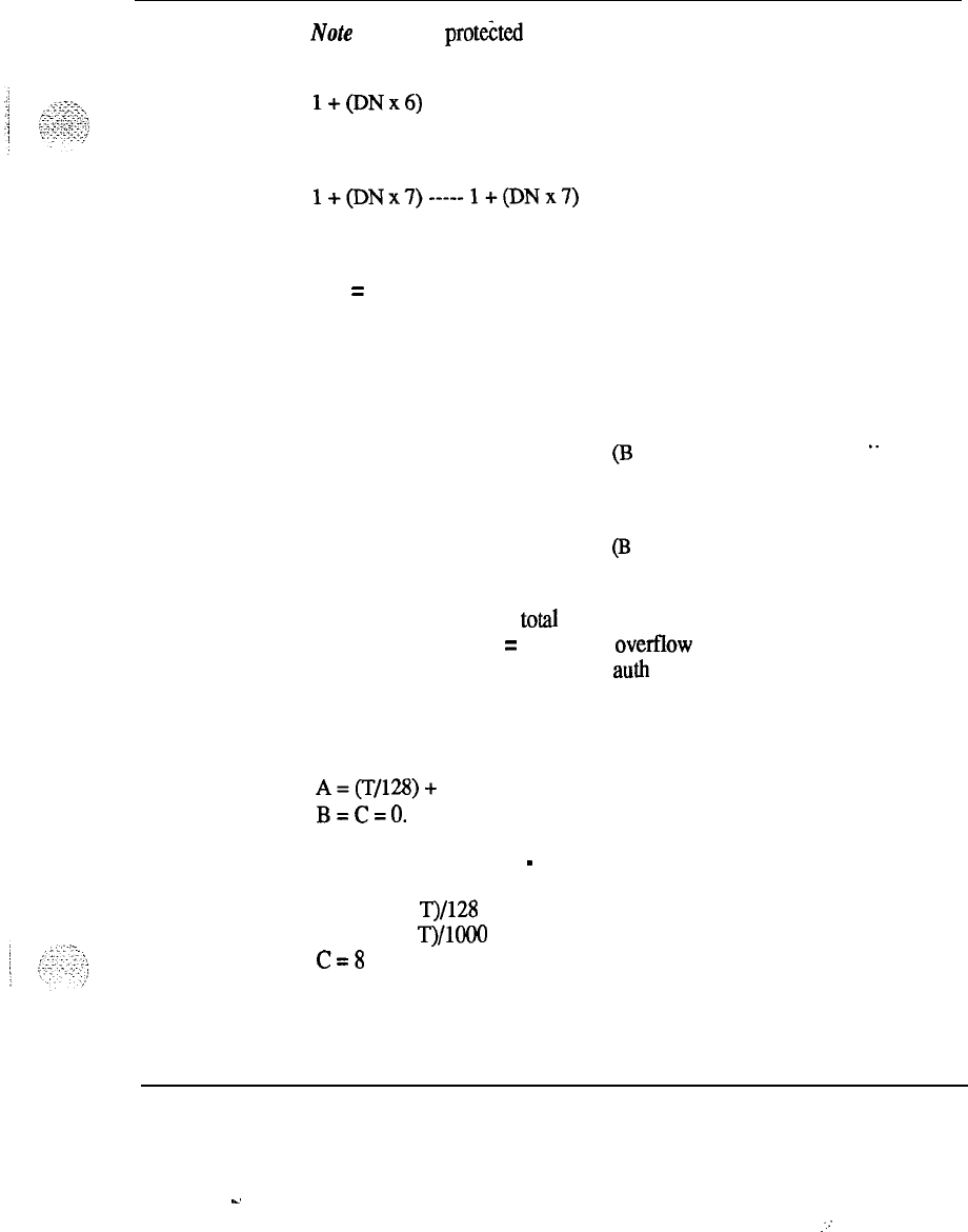
Memory calculations 149
No& 12 : The
protehd
store requirements for DISA (on a per-customer
basis) are:
l+(DNx6)
Release 13 through 15
l+(DNx7)-----l+(DNx7)
where:
DN = number of DISA-DNs.
Note
13 : The protected store requirements for Authorization Code (on a
per-customer basis) are:
1250 + (A x ((L/4 x 128) + 64)) +
(I3
x (1018 + (C x 32)))
Releases 13 through 15:
..
1308 + (A x ((L/4 x 128) + 64)) + (B x (1018 + (C x 32)))
where:
L = digit length
T = total authcode
A = number of overfIow blocks
B = number of auth blocks
C = number of resolution blocks per auth block.
For L less than 4 or L greater than 7
A=(T/128)+
1
B=C=O.
For L in the range of 4
-
7
A = ((0.2 x
g/128
+ 1)
B = ((0.8 x T)/looO + 1)
C=8
Memory calculations 553-2201-l 51 Appendix 1
-.
:..-
150 Memory calculations
Note
14 : History file buffeican be
1-64K.per
customer option.
Note
15 : For System Speed Call List
(XL)
Head Table:
3 + NB/4 + NB (round NB/4 up)
NB (no. of blocks) =
EL/EB
(round any remainder up)
where:
EL = entries per list (given),
EB = entries per block, 256/?VE (round up remainder)
where:
WE = words per entry, DNS/4 (round up)
where: DNS is DN size (given).
Note
16 : IMS protected memory requirements:
APP-SIZE-TBL
= 10 words
MSG-SIZETBL
= 40 words
LTN-TN-TBL
= 255 words
LTN-LINK-TBL
= 65 words
Memory calculations 553-2201-l 51 Appendix 1
s.
Memory calculations 151
Note 17: New
Fletible
Code Restriction (NFCR) requires the following
memory requirements:
1) A 129 word block that contains:
(a) A 128 word table that contains the pointers to the.FRL block for
each route.
(b) A pointer to the tree root address table.
2) A table that contains the pointers to the NFCR trees. Its length is defined
by the maximum number of trees (defined in the customer data block).
3)
Four words are required for each route that has defined FRL codes.
4) Storage for customer defined trees. Amount of memory used depends
on the size of the code restriction trees the customer has defined.
It is possible to calculate an upper bound for the amount of memory that a
tree is using by applying the following formula:
. .
1) The INIT condition occupies 12 words, or 14 words in R12-14.
2) For each digit sequence after the INIT condition:
(a) If the digit sequence is greater than 1 digit, memory required = (3 x
number of digits)
-
4.
(b) If the digit sequence has a count field, memory required for digit
sequence increases by 1.
(c) If the digit sequence is from a BYFS, memory required for digit
sequence increases by 1.
I
,...
,..
,
.
,
1
.:
Memory calculations 553-2201-l 51 Appendix 1
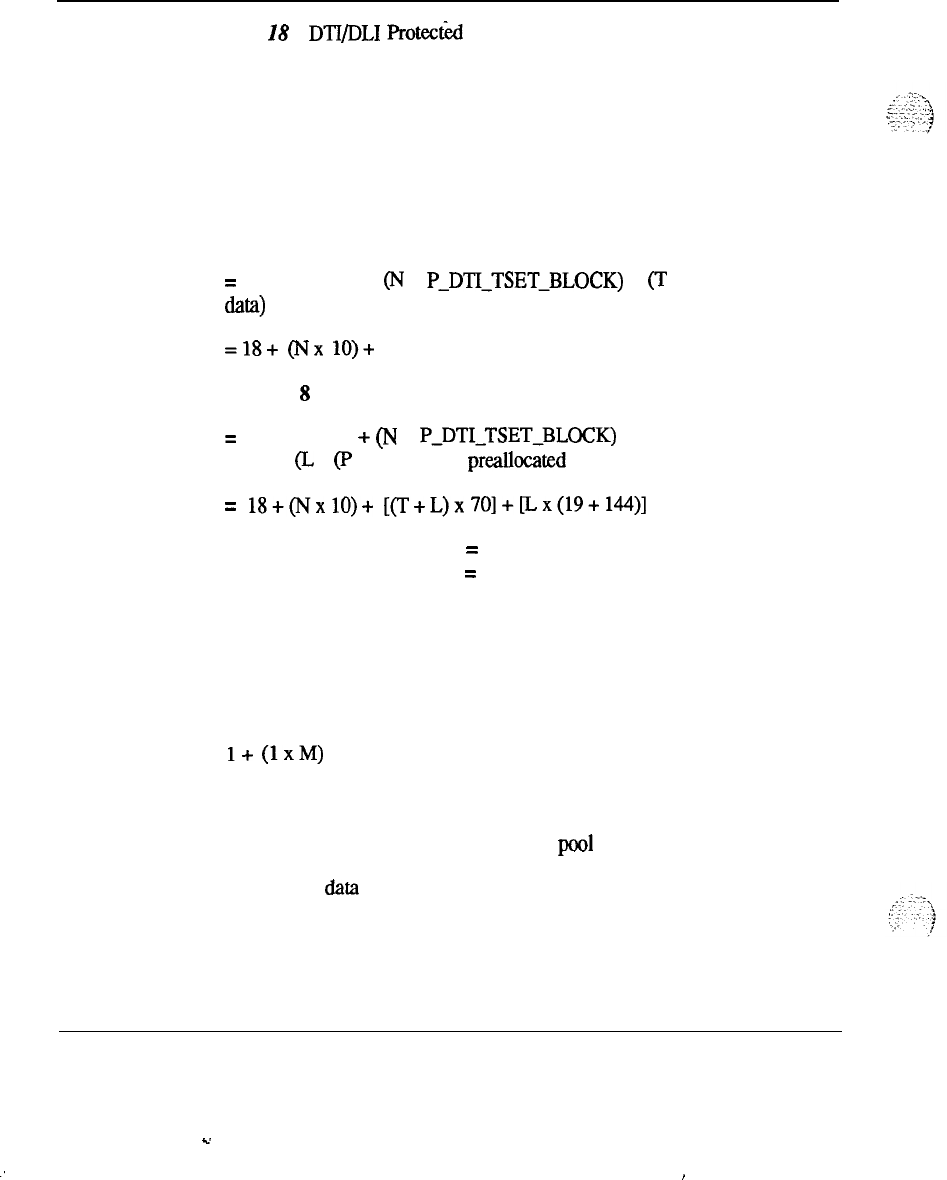
152 Memory calculations
Note 28 : DTI/DLI Protect&l Data Store requirements:
Releases 4 and 5
PDD-BLOCK =
12 words
PAD-TABLE = 36 words
MISCELLANEOUS =
2
words
TOTAL=
50 words
Release 7
=
PDD-BLOCK +
(N
x
PADTI-TSETBLOCK)
+
(T
x local network
d-1
=18+
(Nx
lO)+
(TX 70)
Releases 8 through 15
= PDD-BLOCK + (N x
PDTI-TSET-BLOCK)
+ (T + L) x local network
data+ (L x (P LOOP DLI + preallocated card data))
=
18+(NxlO)+
[(T+L)x
7O]+[Lx(19+
144)]
where:
N = the number of threshold sets
T = the number of DTI loops
L = the number of DLI loops.
Note 19 :
The protected data store requirements for the modem pools on a
per route basis (Modem Data Block):
l+
(1xM)
where:
M = greatest member number in modem pool route
Other AMP data store requirements have been added to their respective
fields.
Memory calculations 553-2201-l 51 Appendix 1
s.
:
,

Memory
calculations
153
Note 20 : The size of the protected multiple office code screening line
block is determined from the following:
2
words for each NXX code defined
2 words for each range defined (maximum_ 20 ranges perlocation code
-
80
words pds).
Note
21 : Templates are incremented in blocks of 10 words.
Note
22 : The trunk block size is 11.5 words with ODAS,
or 14.5 words in Releases 10 and
12,
or 19.5 words in Releases
13
and
15.
Note
23 : Requirements for voice/data port are the same as an SL-1 basic
telephone (Note 2) except the key layout portion of the template requires:
Before Release 9:
(24 + # of non-key features)/# of telephones sharing the same template-
After Release 9:
(10 + # of non-key features)/# of telephones sharing the same template.
Note
24 : Requirements for voice/data port are the same as an SL-1 basic
telephone (Note 2) except the key layout portion of the template requires:
Before Release 9:
(24 + # of non-key features)/# of telephones sharing the same template.
After Release 9:
(12 + # of non-key features)/# of telephones sharing the same template.
Memory calculations 553-2201-151 Appendix 1
154 Memory calculations
Note 25 : Requirements
foi
voice/data port-are the same as an SL- 1 basic
telephone (Note 2) except the key layout portion of the template requires:
Before Release 9:
(34 + # of non-key features)/# of telephones shariqg the same teniplate.
After Release 9:
(21+
# of non-key features)/# of telephones sharing the same template.
Note 26 : Requirements for voice/data port are the same as an SL-1 basic
telephone (Note 2) except the key layout portion of the template requires
(44 + # of non-key features)/# of telephones sharing the same template. For
M3000 data port, requirements are the same as an SL- 1 basic set (see Note
2).
. .
Memory calculations 553-2201-151 Appendix 1
Memory calculations
155
Note 27 : Protected-data store required by
.the
Multi-Tenant Service feature
includes the following:
1028 words per customer that enables Tenant Service for:
Releases
4,s
and 7:
= size
(P_TENANTJTRS)
(=644)
+ size
(TEN-CPG-ORDLS)
(=256)
+ size (RTE-CPG-ORDLS) (= 64)
+ size (CPG-DEFS) (= 64)
Releases 8-14:
= size
(PmTENANT-FTRS)
(=644)
+ size
(TEN-CFG-ORDLS)
(=256)
+ size
(RT&CpG-ORDLS)
(= 64)
+ size
(CFG-DEFS)
(=256)
32 words per Tenant access map
= size (ACCESS-ARRAY)
32 words per Outgoing Route access map
= size (ACCESS-ARRAY)
Memory calculations 553-2201-151 Appendix 1

156 Memory calculations
Note 28 : Protected data store requirements for ATM schedule block are as
follows:
Releases
4,s
and 7:
24+((9xNC+l)xNH)
Releases S-15:
24+((9xNC+
l)xNH)+
13xAR
where:
NC = Number of Customers.
NH = Number of hours to be scheduled.
AR = Number of routes to be tested.
.
.
Note 29 : For all machine types, the additional protected data store for a
virtual terminal (DS access TN or VMS access TN) is exactly the same as
for an SL-1 set, with one exception. For any of the two TN types, the Card
Block Component is dependent on the shelf/card to which the terminal is
assigned. The component is 0 if the TN is on a preallocated card, or 1.5
words otherwise. A preallocated card may be one of the following
shelf/cards: O/l
-
O/7,
l/l
-
1/8,2/l
-
2/8 or 3/8 on a DLI loop. See Note 18.
Memory calculations 553-2201-151 Appendix 1
I
Y
Memory calculations
157
Note 30 : The protected data store requirement (in words) for VAS Data
Services per customer, for each customer that has at least one DSDN, is:
=
DSDN-VASJBL
+ (DSDN-LIST x N)
16+
(39
+
N)
where:
N = the number of VAS for which at least one DSDN is defined.
Releases 10 and 12
=
DSDN-VAS-TRL
+ (DSDN LIST x N)
16+
(248
x
N)
Release 14 and 15
=
DSDN-VAS-TRL
+ (DSDN-LIST x N)
16 +
(76xN)
where:
N = number of VAS for which at least one DSDN is defined.
-
Note
31
:Requirements for a Voice/Data port are the same as an SL- 1
basic set (see Note 2), except that the key layout portion of the template
requires 34 + # of non-key features
/
# of sets sharing the same template.
For M2317 data ports, the requirements are the same as the SL- 1 basic set
(see Note
2).
,
..-;;
::.:.>t,
-, ,
-
_
.
.
.
,’
,:,-.
..-
..,.
.:
_-,
!
_..:
Memory calculations
553-2201-151
Appendix 1
.
.
.-
I
158 Memory calculations
Note 32
:Protected data stdre requirements for CPND per system in words
is:
where:
C = number of customers
SL = number of non-PBX DNs with or without name defined
(including trunk routes, ACD
ATIN,
and SL- 1)
SP = number of single appearance PBX DNs with name defined
DIG = number of DIG Groups
* = 101 for 2-digit DIG Groups
N = Name length
NA = number of Names.
Note 33 : For each PR loop configured, add 5 words for the
P-PREP-BLOCK to the PTERM LOOP-BLOCK.
Memory calculations 553-2201-l 51 Appendix 1
.
.
Memory calculations 159
Note
34 : Each system that has DCHIs shares
P-DCH-TBL
which has 16
words in length. Each DCHI consists of the following protected data blocks:
P-DCHBLOCK
= 23 words
Releases 13 and 14:
P-DCH-BLOCK
= 25 words
Release 15:
PDCH-BLOCK
= 26 words
Protected call reference table = 1 + (24 x # of PRI loops controlled by
DCHI). If DCHI is in PRA mode, add the following:
Protected call reference table = 1 + (maximum number of ISL trunks
defined) if DCHI is in ISL mode
. .
Protected call reference table = 1 + (24 x # of PRI loops controlled by
DCHI) + (maximum number of ISL trunks defined) if DCHI is in SHARED
mode.
Note
35
:
For each ISA route configured for IFC = ESS4, add 2 words for
the ISA-SRVCBLOCK.
With Releases 14 and 15, if IFC = ESSY, add 4 words for the
ISA-SRVCBLOCK.
Note
36 : A pointer named ISA-SID-MTHPTR has been added to fix
memory. This pointer is set to nil when SID is not defined for ISDN routes.
A data block of 32 words is defined and accessed through this pointer if SID
is defined for at least one ISDN route in the system. This data block
contains pointer to SID tables for each customer. The structure mapping
onto this data block is ISA_(3uSTID_TPTR.
Memory calculations 553-2201-l 51 Appendix
1
-.
‘:’
160 Memory calculations
A data block of 64 words is allocated for each customer if at least one route
is defined to have SID. The structure mapping onto this data block is
ISA-SID-RT-LIST.
Note 37 : Protected ISL Trunk TN table =
l+
maximum number of ISL
Trunks defined.
Note 38 : The protected customer data per customer defined is as follows:
B+(Xx@‘+A))
where:
P = Protected customer data block (255) (262 in Release 15)
A = auxiliary customer data (14)
B = 1000 for XN, XT, RT, and NT machines
320 for all other machine types
X = number of customer groups defined
If background terminal is equipped, an additional auxiliary data block is
allocated which requires 35 words. This brings the total requirement to 305
words.
Note 39 : No protected storage is required unless the system is equipped
with the Speed Call package (66) and the entry to MSCL prompt in Overlay
17 is greater than 0. In this case, the protected memory required for SCL
main header table is:
words required = N + (1 x A)
where:
N = 1 (number of header words)
A = number of SCL as defined in Overlay 17 (MSCL prompt)
‘.
:
,
::-
:.
.
.
:.
.
,_..-
3
”
‘.:
:’
7
‘.’
/
Note 40 : For each customer, an additional 255 words is needed for
PREXI-SCLN
in pool CDB (compool).
Memory calculations 553-2201-151 Appendix 1
-.
Memory calculations 161
Note 41 : The protected data store requirements for DTI2 is as follows:
DTI2-SYSTEM-DATA
9 words
DTI2-SCAT-NT
16 words
DTI2-SCTA 16 words
DTI2-FCADA-NT
16 words
-
DTI2J’CADA
16 words
Note 42 : There are 32 pointers to FTC protected structures. Each FTC
table has 90 words
Note 43 : There are 256 pointers to EFTC protected structures. Each
EFTC table has an additional 27 words.
Note 44: A bit is required in the customer data block to indicate EBLF
allowed/denied. A bit is required in the protected attendant block if
attendant consoles have the Console GFraphics Module (CGM) configured.
Additional memory is required only if EBLF is ON. 104 words are ._
allocated in the fixed protected memory even if EBLF is not used.
Words required:
x+((z-3)xyxll)
where:
x = number of customers with EBLF
y = average number of hundreds groups per customer
z = average DN length
(4,5,6,7)
Memory calculations 553-2201-l 51 Appendix 1
k.

162 Memory calculations
Note 45
:
EOW
requires the following
inRelease
15:
per target table 113 words
per source table 174 words
per ACD DN 6 words
The words required for the source table are allocated for every target ACD
DN.
Memory calculations 553-2201-151 Appendix 1
AAB
ACDA
ACDB
ACDC
ACDD
ACDR
AIOD
AMP
Attendant Administration
Automatic Answerback
ACD Basic
ACD Advanced
ACD Management Reoprts
ACD Auxiliary data System
AUTOVON CDR
Automatic Identification od Inward Dial
Automated Modem Pooling
Automatic Number IdentificationANI Route Selection
Memory calculations 553-2201-151 Appendix 1
L’

164 List of terms
ANIR
AOP
I
ATVN
/
AUTH
AWU
BACD
BARS
BAUT
BCSOB
BGD
BQUE
BRTE
CAB
CAS
ANl
Route Selection
Attendant Overflow Position
AUTOVON
Authorization code
Automatic Wakeup
Automatic Call Distribution-Base
Basic Automatic Route Selection
Basic Authorixation Code
SL- 1 Output Buffer
Background Terminal Facility
Basic Queuing
Basic Routing
Charge/Authorization Base Package
Centralized Attendant Service
Memory calculations 553-2201-151 Appendix 1

List
of terms 165
CASM
CASR
CCBQ
CCBQCM
CDP
CDR
CDRE
CDRQ
CFCT
CFNA2
CHG
CLNK
CMAC
CPND
CAS Main
CAS Remote
Coordinated Call Back Queuing
Coordinated Call Back Queuing to Conventional Mains
Coordinated Dialing Plan
Call Detail Recording
CDR Expansion
Emergency Acces Enhancement (911 Option)
Call Forward by Call Type
Call Fortward No Answer
-
Second Level
CDR with Charge Account
CDR with Magnetic Tape
ESN Communication Management Center
Call Party Name Display
Memory calculations 553-2201-151 Appendix 1
166
List of terms
CPRK
CTY
1
!
CUST
DDSP
DHLD
DI
DISA
DLDN
DND
DNDG
DNDI
DNIS
DNXP
DRNG
Call Park
CDR
TIT
Multi-Customer
Digit Display SL- 1 Set
Deluxe Hold
Dial Intercom
Direct System Inward Access
Departmental LDN
Do Not Disturb
DND Group
DND Individual
Dial Number Identification Service
Directory Number Expansion
Distinctive Ringing
Memory calculations 553-2201-151 Appendix 1
c

List of terms 167
DSET
DTI
EES
EOVF
FCA
FCBQ
FTC
GRP
HIST
HOT
IAP3P
ICDR
IDC
IMS
Digital Set M2000
Digital Trunk Interface
END-to-End Signaling
EWnhanced Overflow (NACD)
Forced Charge Account
Flexible Call Back Queuing
Flexible Tone and Digit Switch Control
Groupe
Call
History File
Hot
Line
Services
Enhanced Hot Line
Flexible Hot
Line
Integrated Services Digital Network Application Protocol
Internal CDR Records
Incoming DID Digit Conversion
Integrated Messaging System
Memory calculations 553-2201-l 51 Appendix 1
-.
._
:.
.
.‘.
‘....
:
168 List of terms
INTR
ISA
ISDN
ISL
IVMS
LLC
LMAN
LNK
LSEL
MCBQ
MCT
MOD
MOH
MR
Intercept
Integrated Services Access
Integrated Services Digital Network
Integrated Services Digital Network
Integrated Services Digital Network Signaling Link
Integrated Voice Messaging System
Line Load Control
ACD Load Management
Auxiliary Processor Link
Line Selection
Network Queuing
-
Main
Malicious Call Trace
Music on Delay
Music on Hold
Message Registration
Memory calculations 553-2201-151 Appendix 1

List of terms 169
MSB
MUS
MWC
NARS
NAUT
NCOS
NFCR
NSC
NSIG
NTRF
NTWK
NXFER
occ
ODAS
Make Set Busy
Music on Hold
Message Center
Network Automatic Route Selection
Network Authorization Code
Network Class of Service
New Flexible Code Restriction
Network Speed Calling
Network Signaling
Network Traffic
Network Ring Again
Network Transfer
Other Common Carriers
Office Data Administration System
Memory calculations 553-2201-l 51 Appendix 1
.
.
‘..’
170
List of terms
OHQ
OPAO
OPTF
PBXI
PBXOB
PMSI
PQUE
PRA
RAN
RESDB
RMS
ROA
RPE
see
Off Hook Queuing
Out-pulsing of Asterisk and Octothorpe
Advanced Features
PBX Interface/Digital Trunk Interface
Non SL-1 Output Buffer
Property Management system Interface
Priority Queuing
Primary Rate Access
Recorded Announcement
Resident Debug
Room Status Service
Recorded Attendant Overflow Announcement
Remote Peripheral Equipment (1.5 Mb/s)
Special Common Carrier
Memory calculations 553-2201-151 Appendix 1
.
.
:
.
.
List
of.terms
171
SCI
SLP
SNR
SR
ssc
ss5
SS25
TAD
TDET
TENS
TOF
TSET
UMG
UST
Station Category Indication
Station Loop Preemption
Stored Number Redial
Set Relocation
System Speed Call
500 Set Access to 2500 Set Features
2500 Set Features
Time and Date
Tone Detector
Multi Tenant Services
Time Overflow Queuing
Digital Set M3000 (Touchphone)
User-to-User Teleset Messaging
User Status
Memory calculations 553-2201-151 Appendix 1

172 List of terms
Memory
calc&tions
553-2201-151 Appendix 1
-.
‘2

List of terms 173
Memory calculations 553-2201-151 Appendix 1
-

SL-1
Generic Xl 1
Memory calculations
Q
1984 Northern Telecom
All rights reserved.
Information subject to change without notice.
Release 1 .O
Standard
December 1989
Printed in U.S.A.
SL-1
System options
21,51-,
61,71
Power engineering
Standard


SL-1
System options
21,51,61,71
Power engineering
Publication number: 553-3001-l 52
Document status: Standard
Document release: 1 .O
Date: January
29,199O
.
.
.
-,.:..,-..
0
1990 Northern Telecom
All rights reserved.
Power engineering 553-3001-l 52

Revision history
January 29,199O
Standard, release 1
.O
Power engineering 553-3001-152
.
.
.
III
About this document
This document describes the SL-1 System power and grounding architecture
for both AC and DC systems and provides guidelines for calculating system
power consumption as well as reserve power requirements.
References
For information about the power plant used with DC-powered system option
7 1, see the following publications:
-
J2412A-Description,
Engineering, Ordering Information, Installation,
Connections, Operation and Maintenance
(167-2191-200)
-
NT5CO3
Switched Mode
Rectijier
-48Vl5OA
-Description, Maintenance
and Ordering Information PO673491
(169-2031-200)
See the SL-1 planning
&
engineering guide for
-
Master index
(553-3001-000)
-
System overview
(553-3001-100)
-
Installation planning
(553-3001-120)
-
System engineering
(553-3001-151)
-
Power engineering
(553-3001-152)
-
Spares planning
(553-3001-153)
-
Equipment identification and ordering
(553-3001-W)
-.
:/ ,.
::
.A?‘.
~‘.<
_-
-‘.‘,
:‘.I:
:;.
._
. .
‘.
-:
See the list of line and trunk circuit descriptions in the
Master index
(553-3001-000) for specific references to lines and trunks.
Power engineering 553-3001-l 52
iv
About this document
See the SL-I installation a&f maintenance guide
for
-
System installation procedures
(553-3001-210)
-
Circuit pack installation and testing
(553-3001-211)
-
Installation procedures for telephone
sets and attendant consoles
(553-2201-215)
-
-
Extended systems installation
(553-3001-250)
-
Disk drive upgrade procedures
(553-3001-25 1)
-
General maintenance information
(553-3001-500)
-
Fault clearing (553-3001-510)
-
Hardwart replacement
(553-3001-520)
See the SL-I XII sofhvare guide
for an overview of software architecture,
procedures for software installation and management, and a detailed
description of all Xl 1 features and services. This information is
contair&
in
two documents:
-
XII
sofmare
management (553-3001-300)
-
XII features and services (553-3001-305)
See the SL-I XII input/output guide
(553-300140) for a description of all
-
administration programs, maintenance programs, and system messages.
Power engineering
553-3001-152

Contents
SL-1 system power overview
1
General information
1
AC or DC powering
2
AC power system description
Input power specifications
Internal power distribution
External power distribution and ground connections
General notes for AC figures
5
.
5
6
11
13
DC power system description 19
Input power specifications
19
Internal power distribution 20
External power distribution and ground connections 25
General notes for DC figures 25
System grounding
31
Single Point Ground 32
Additional requirements 33
Isolated ground topology 33
Non-isolated ground topology 34
Operating power requirements 35
Introduction 35
Circuit pack power consumption 35
Module power consumption 37
System power calculation guidelines 38
Thermal considerations 44
Power engineering 553-3001-l 52

vi Contents
Reserve power 47
AC reserve power 47
DC reserve power 53
Engineering and configuration guidelines 57
AC power architecture 56
Internal AC power equipment components 56
DC power architecture
61
internal DC power equipment components 62
External DC Power equipment components 63
Commercial power and grounding requirements 66
Power conductors 69
Wire size calculation guidelines 69
Examples
.71
,.Kiz-..
.
.
.
.
..d..
,_
._,._.
.
-
.
.
.
I
. .
.
.
I.-.^..
-..._..~
1
L’
.“.‘,~-,
.
.
.5
List of terms 73
Power engineering 553-3001-152

SL-1 system power overview
The SL-1 system is an advanced telecommunications system providing state
of the art functionality to the customer. The associated power system provides
the necessary power for system operation.
General information
The power system required by the SL- 1 system can be divided into two main
categories: external and internal.
The external system consists of the power source and power plant which is
located outside of the SL-1 system. This includes the power plant and the
reserve power plant, if required, as well as the distribution and grounding
components.
-
The internal system consists of the hardware within the SL-1 system which
distributes and converts power. This is made up of a specific power
distribution unit (PDU), shelf power converters or power supplies as well as
distribution cables and grounding hardware. The internal system is chosen to
suit the existing or specified external power system and cannot be changed in
the field.
There are two basic powering schemes which cause both the internal and the
external hardware to change
-
AC powering and DC powering. The choice
of which powering scheme to use is up to the customer and is determined by
system cost, reserve power requirements and the type of existing equipment at
the
site. See Installation
planning
(553-3001-120). Figures 1 and 2 show the
two basic schemes. Note that both require a source of commercial AC power.
In Figure 2, because of the required rectifier, it is referred to as the DC system,
which means that the PBX will require a nominal 48 V dc at its input
terminals located in the pedestal. The PBX in Figure 1 requires a nominal
208 or 240 V ac at its input terminals located in the pedestal.
Power engineering 553-3001-l 52

2SL-1 system power overview
In discussing these powering schemes, unless otherwise specified, AC
distribution will mean a single phase circuit without a neutral conductor, but
with an accompanying green wire ground conductor. The nominal voltage is
assumed to be either 208 or 240 volts but any voltage within the range shown
in Table 1 is applicable. DC distribution is typically a nominal 48 volts at the
input to a UEM power converter under load.
-
AC or DC powering
DC powering and AC powering differ primarily in the use of rectifiers. DC
systems always require the use of rectifiers (see Figure 2). This is a cost
disadvantage for DC in applications that do not require “backup” in the event
of a utility power failure. The reason for this is due to the double conversion
that is required: line voltage to -48 V dc and then 48 V dc to the required
circuit voltages. AC powering, on the other hand, requires only a single
conversion
-
line voltage to the required circuit voltages.
The use of a rectifier in DC powering does however become a cost advantage
in applications that require battery backup. The reason for this cost advantage
is that an AC Uninterruptible Power System (UPS) consists of not only a
rectifier but also requires the additional cost of an inverter. Both AC and DC
require similar battery banks so there will not be much of a cost advantage or
disadvantage with these battery plants.
The actual distribution of DC and AC power is similar. DC power will
be
brought into the Pedestal and distributed to the Modules in a similar way to
AC power, the difference being that AC uses AC-to-DC Power Supplies
rather than DC-to-DC Converters.
Note:
The DC system requires the use of additional input wires in order
to handle the lower voltage and its associated higher current.
Power engineering
553-3001-152
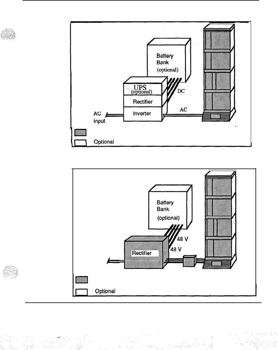
SL-1 system power overview 3
Figure 1
AC powered system
,
Figure 1
AC powered system
I
M
Required
I
Chtionnl
Figure 2
DC powered system
AC
b
input
I
m
Required
Power engineering 553-3001-152

4SL-1 system power overview
Power engineering 553-3001-l 52
-.
:i
,.
../
:.: :.:-
3:
:.:
:
,._.
_...
_
.;
“.f.
.;::‘r,>
--,.,
5
AC power system description
This section describes the characteristics of the Meridian SL-1 system where
equipment columns are directly powered by commercial power.
The commercial power voltage is brought directly into the Pedestal Power
Distribution Unit. From there it is passed through separate wiring to the
individual modules in order to provide power to the module power supplies.
I.
Input power specifications
AC power supplies operate at a nominal 2081240 V. A typical system
operating from 208 V using four UEMs
will
draw 15-24 Amps, depending on
the configuration. These are fed from a central point in the pedestal, access to
these connections is provided and should be used to confirm that the line -_
voltage is within the required range as indicated in Tables 1 and 2.
Table 1
AC input specifications
Input Minimum Nominal Maximum
Voltage (V ac) at pedestal 180 2081240 250
Frequency (Hz) 47 50160 63
Current to a pedestal
-
see note
24A
Note: Current is dependent on equipment installed see “Operating power
calculation guidelines.”
Power engineering 553-3001-152
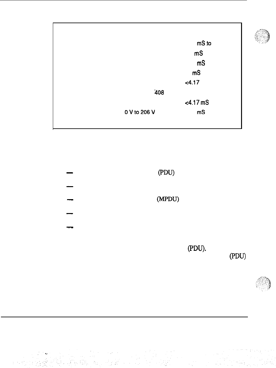
6AC power system description
Table 2
Transient tolerance
Transient tolerance Amplitude Duration
(See note)
Surges 288
U ac
8.34
mS
to
50 ms
276 U ac 50 mS to 500 ms
Sags
146Uac 8.34
mS
to 50 ms
166Uac 50
mS
to 500 ms
Spikes 815 Upk ~4.17 ms
815 U pk to
‘408
U pk 4.17 to 8.3 ms
Notches
to ou
~4.17
mS
OUto206U
4.17
mS
to 8.3 ms
Note: All transients are applied at the peak of the AC waveform.
.
Internal power distribution
Figure 3 shows the internal AC power distribution elements:
-
Pedestal Power Distribution Unit (PDU)
-
Module to Module Harness
-
Module Power Distribution Unit (MPDU)
-
Module to Backplane Harness
-
AC Power Supplies
The power cables enter the Pedestal and connect to the Field Wiring Terminal
Block which is located in the Power Distribution Unit (PDU). From that
terminal block, the AC voltage passes into the Power Distribution Unit (PDU)
which has a single circuit breaker providing power to each of the four modules
and the cooling fans. The System monitor runs off a small AC Power Supply
which operates independent of the circuit breaker. Module to Module
distribution produces individual AC power to each module.
Power engineering 553-3001-152
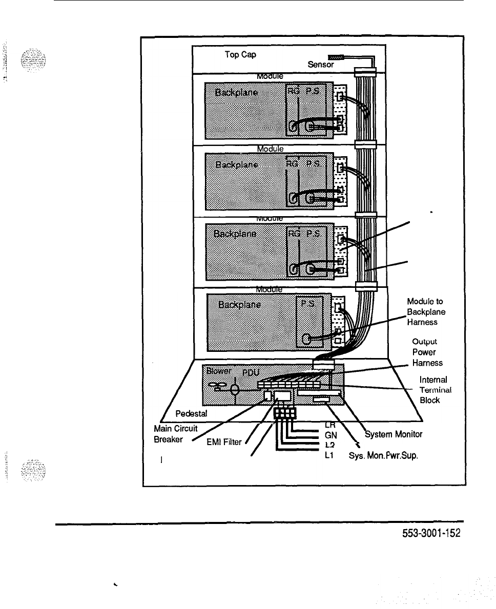
AC power system description 7
Figure 3
AC internal power distribution
Module
-
PDU
.
Module to
Module
Harness
/
/
Field Wiring Terminal Block SY:.
Mon.? Wr.Sup.
.
.
Power engineering
553-3001-152
8AC power system description
Pedestal Power Distribution Unit (PDU)
The Pedestal PDU provides the following:
-
The Field Wiring Terminal Block provides a connection point for the
external wiring that is brought into the Pedestal.
-
The EM1 Filter provides filtering of the wires connecting back to the
Utility in order to meet FCC and DOC requirements.
-
The Main Circuit Breaker provides both a single protection device for
overload currents and a single trip device to shut down the column in the
event of a thermal overload.
-
The Internal Terminal Block provides individual power hand-off points so
that each Module is independently powered from the Pedestal in order to
minimize wire size.
.
-
The Power/Signal Harness provides the Power and Signal interconnections
in the Pedestal for the Blower Unit and System Monitor.
. .
-
The System Monitor Power Supply (a small +5V power supply) provides
power to the System Monitor, even when the main circuit breaker has
tripped.
-
The Output Power Harness provides the independent power connections
from the Pedestal to the Module above it.
-
Module to Module Harness
The Module to Module Harness provides the following:
-
The Module Feed provides the independent power feed(s) to the Module
above itself.
-
The Module PDU Feed provides the power feed to the Module PDU.
Module Power Distribution Unit (MPDU)
The Module PDU provides the following functions:
-
The Circuit Breaker provides a Module level of current protection so that a
fault on one Module will be disconnected while the other Modules remain
functional.
e-
,-..--
_.,,.
-,-.
-3
-
The MPDU to Backplane Harness feed provides the power feed to the
backplane harness which in turn provides power to the AC Power
Supplies through the backplane power connector.
Power engineering
553-3001-152
.
.
.,
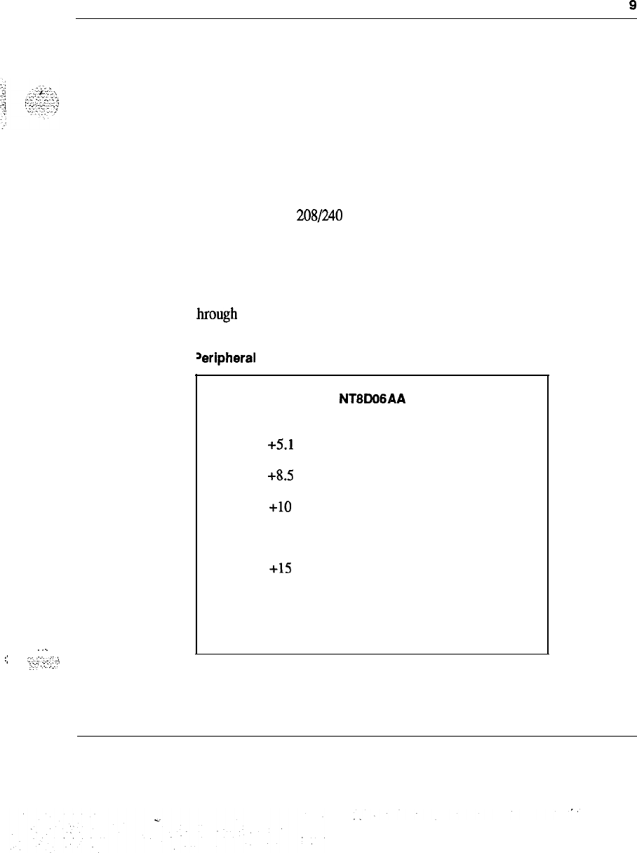
NTBWGAA
output vOutput A
+5.1
v 28 A
+8.5
V4.0 A
+lO
v 0.5 A
-lov 0.5 A
+15
v 17A
-15 v
15 A
-48V 7.7 A
;
.
.
.
::
y.:::..:
.,.,
‘:-;
,2:-j;.
i
AC power system description
9
Module to Backplane Harness
The Module to Backplane Harness provides the power to the AC Power
Supplies through the backplane power connector.
AC Power Supplies
There are three different power supplies that provide power to the Peripheral
Equipment, Common Equipment and Common/Peripheral Equipment
Modules. In addition, the Ringing Generator provides ringing voltage for the
Peripheral Equipment Modules.
At each shelf, the 208/240 V ac is received through the backplane distribution
harness and converted to the necessary voltages for the individual module.
Circuit breakers are located on each MPDU to provide for safe operation and
easy maintenance.
The output voltages and currents of the power supplies are listed in Tables 3
brough 6.
fable 3
Deripheral
Equipment Power Supply
Power engineering 553-3001-l 52
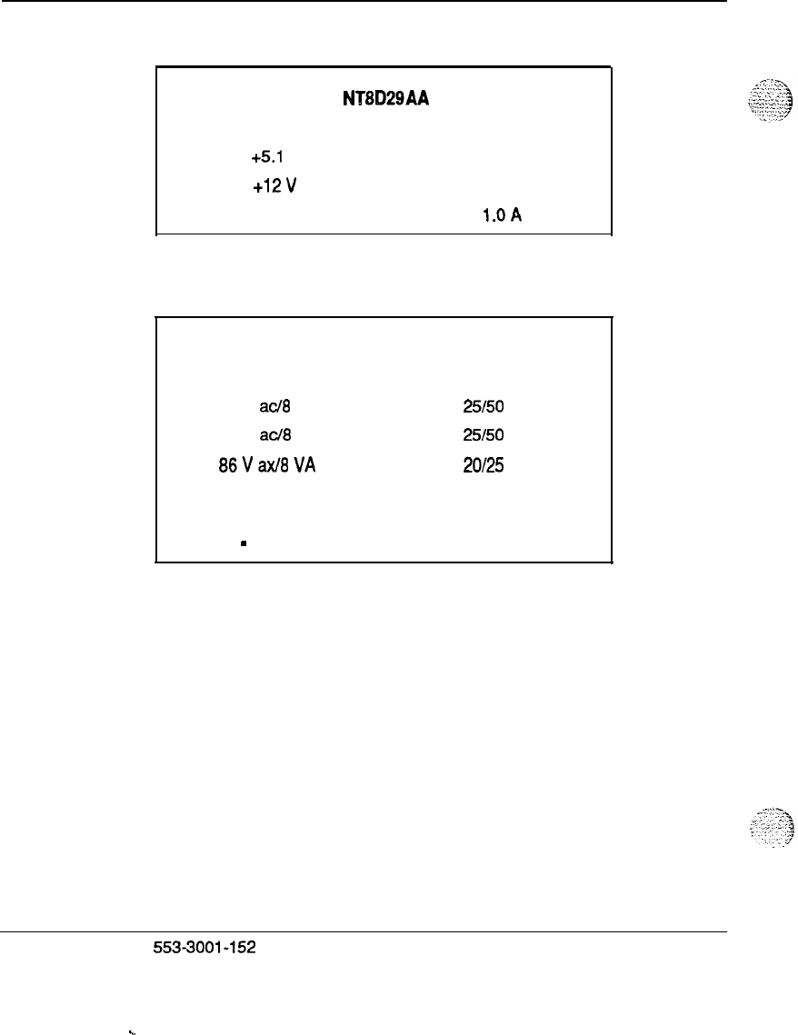
10
AC power system description
Table 4
Common Equipment Power Supply
NT8D29AA
output voutput A
+5.1
V 60A
+12v
2.5
A
-12 v
l.OA
Table 5
Ringing Generator
NT8021 AA
Output VNA
Output
F
70 V
ac/8
VA
25150
Hz
80 V
acl8
VA
25150
Hz
06Vaxf6VA
20125
Hz
output vOutput A
-
150v
0.200
A
Power engineering
553-3001-152
.
.
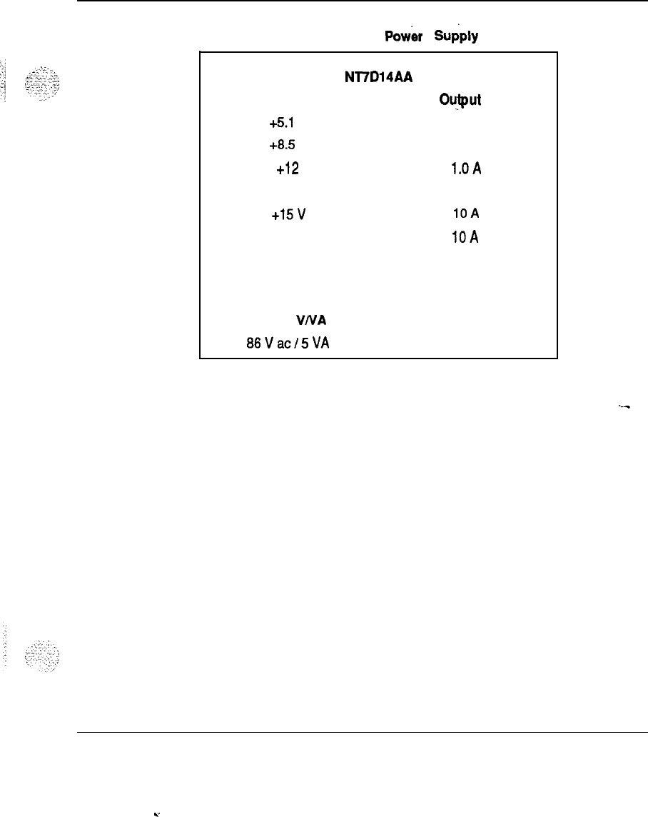
AC power system description 11
Table 6
Common/Peripheral Equipment Pow& Supply
Nl7D14AA
output vOuJput
A
+5.1
V 60A
+8.5
V
2.5
A
+12
l.OA
-12 0.75
A
+15v
10A
-15 v
IOA
-48 V 4.75
A
-150 v
0.13 A
output VIVA Output F
86Vacf5VA
20
Hz
External power distribution and ground connections
.-_
The external distribution for AC powered systems is very simple. No
additional equipment is required; simply connect to an AC source of power.
One 208 or 240 volt circuit with 30 amps protection (circuit breaker or fuse)
should be used to feed each pedestal.
Figure 4 shows the important grounding connections and the use of the ACEG
(AC Equipment Ground) or IGB (Insulated Ground Bus). For a general
discussion of the grounding philosophy, see the section “System grounding.”
Figures 5 through 8 for AC distribution in this section are shown for
connection to standard utility power. If an Uninterruptible Power System
(UPS) is used, refer to the later section on AC reserve power.
Power engineering 553-3001-l 52
.
.
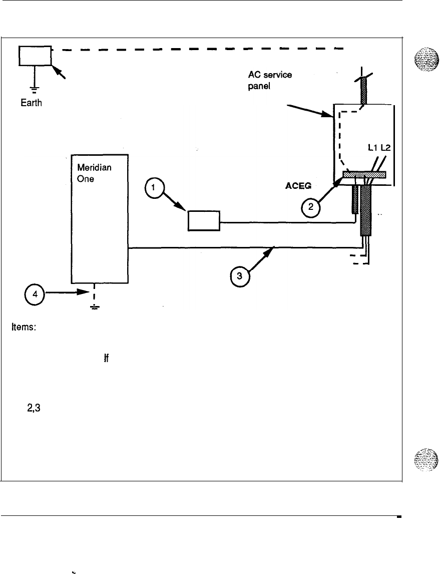
12 AC power system description
Figure 4
Grounding and equalizing nodes
-----H--s------------H--s-------
99
11
Building groundBuilding ground
EaZhEaZh
rodrod
hems:
1.
An equalizing node for the Meridian SL-1 system may be obtained through the ACEG
the AC panel. ff isolation as per NEC 384-127 (exception 1) cannot be provided,
an alternate low impedance connection to the building ground may be required.
In either case there are many constraints which must be observed. such as:
2,3 The NEC and CEC require exposed metal (Meridian 1 cabinet) be grounded by an
ACEG
4.
Stray connections to a foreign ground will bypass the single point concept.
In high rise buildings large potentials can exist between an ACEG and other
grounds including building steel.
Power engineering 553-3001-l 52
.
.

,:
,,
..,
c.
i....,
::,
..
..!,
;:;::
:.-I
:I
:,
,“:-:-‘;
AC power system description 13
General notes for AC figures
Permanent connection to Branch Circuit
When conduit or a raceway is
used it should be metal and regardless of the type, it must contain an insulated
ground wire (green), 6 AWG or larger.
Cord connection to Branch Circuit
A separate safety ground is always
required when removable line cords are used for the following reasons:
-
a telephone wire could contact AC elsewhere in the building while the cord
is unplugged (during installation)
-
to minimize hazards from lightning transients when unplugged
-
to minimize the effects of stray grounds (pedestal to floor RS-232 links to
monitors) during normal operation
The additional safety ground must be 6 AWG or larger, preferably insulated
and must be connected from the pedestal Frame Ground to the Service Panel
Ground Bus
. .
One 30 Amp circuit per pedestal is required. Isolation as required by NEC
250-74 and 384-27 (Exception 1) is preferred.
Single Point Ground (SPG) and Isolated Ground Bus (IGB) The SPG in
this grounding scheme is the Equipment Grounding Terminal Bar in the AC
distribution panel
(ACEG).
If this bar is isolated from the distribution panel,
as is recommended, then it is referred to as an IGB. In the following figures,
the preferred method using an ACEG is illustrated.
Logic Return (LR) wiring and Logic Return Equalizer (LRE) location
When
multiple columns are present or where links will be made to existing SL-1
equipment, the LRs of the different columns must be joined. See
System
installation procedures
(553-3001-210). An LRE (a bar or plate) in the
immediate vicinity allows the LRs to be joined to a single equalizing point. A
6 AWG conductor then connects the LRE to the IGB in the AC panel.
For these multiple column applications, the LRE is typically located in a
nearby rack, overhead trough or under a raised floor, It must be insulated
from its support structure.
Power engineering 553-3001-l 52
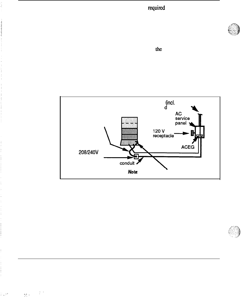
14 AC power system description
Note:
This single point equalizing is reqmred because communication
between modules that are not in the same physical line-up would put
small amounts of DC on the AC (green wire) ground. Likewise residual
AC voltages would be superimposed (longitudinally) on the logic. There
/:
--
is a only a few volts of common mode rejection capability on these lines.
g;c-;::,:,
$
-3
F”‘:
.:“>,
‘L!y
Refer also to the System Grounding section later in this document.
120 V receptacles and cord or conduit items in the figures are used only as
required.
Single column AC powered system
A single column system can be easily powered as shown in Figure 5.
Figure 5
Single-column distribution
AC in
cl
incl. main
groun )
Y
cord or conduit
as required
\
208i24OV
receptacle
Nota Internal strap from LR to FG
Power engineering 553-3001-152
..
:
.:
..
,..

AC power system description 15
Multi-column AC powered system
A multi-column system (with one or more columns physically adjacent to
each other) can be powered as shown in Figure 6.
Figure 6
Multi-column distribution
cord or
conduit
AC in
AC service
panel .
120v
receptacle-
’
!
ACEG
receptacles
Note 1:
This LRE may be a simple insulated connector , or if
preferred, run the LR conductors separately to the
ACEG.
_-
Power engineering 553-3001-152
.
.
.:.
::.
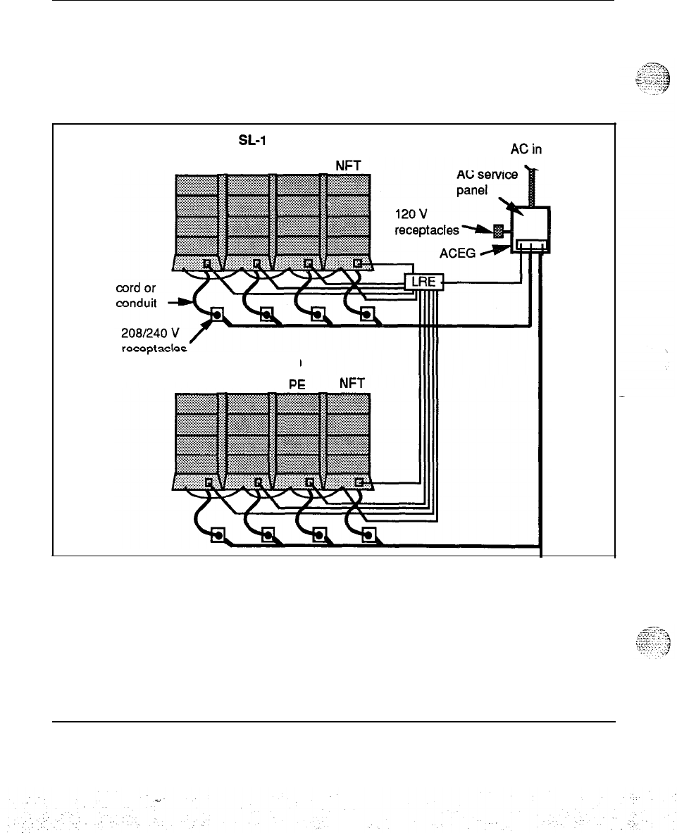
16 AC power system description
Multi-row AC powered system
A multi-row system (with several rows of one or more columns physically
adjacent to each other) can be powered as shown in Figure 7.
!
Figure 7
Multi-row distribution
SL-1 System
PE
JUNCT CPU
. .
SL-1 System
PE PE
Power engineering 553-3001-l 52
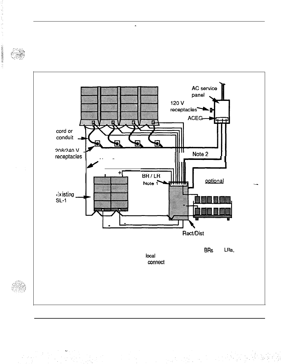
AC power system description 17
Extended systems
-
A typical large extended
system
with both new and existing equipment is
. . .
. .
.:.
L
‘...’
:
.‘.*
shown in Figure 8.
_,.
,
..:
”
p.:
y..y+;‘j
.\
..y-,-*.r,
..~...‘:;;
Figure 8
External distribution for AC systems
SL-1 System
AC in
III
II
Note
-1
E
iX
istir
H
Note 3
+
+-
Battery plant
---
Rect/Dist cabinet
(QCA13)
Notes:
1. The rectifier cabinet will contain a bus for terminating
BRs
and LRs, but
if the runs are too long,
a
looal
LRE may be needed. See ‘General notes
for AC figures.” It should still oonneot to this bus.
2. This conductor and the safety ground must be 6 AWG minimum but
may be larger, depending on battery fusing.
3. May be run independently to ACEG.
Power engineering 553-3001-l 52

18 AC power system description
-.-
---
,._
._
r.-
.
.
.
i;
.
.
.
.I
Power engineering 553-3001-152
.
.
,
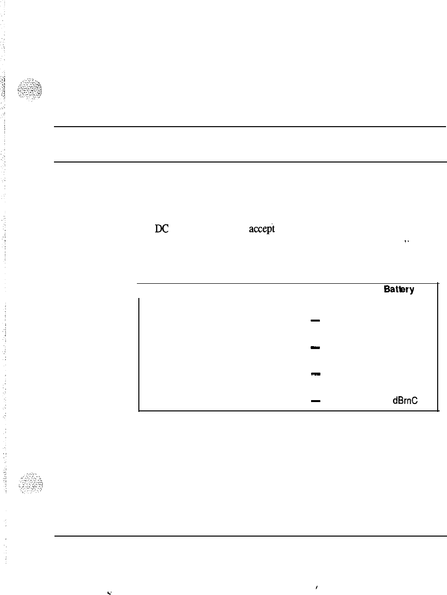
DC power system description
19
This section outlines the characteristics and requirements for the DC auxiliary
power that the system is connected to.
Input
power specifications
The DC supply chosen must accect the calculated current drain and operate
within the following specifications:
I.
Table 7
input specifications
I
Input
Maximum range
Expected nominal (with 24
stationary cells)
Expected nominal (with 23
sealed cells)
Expected nominal (with 24
sealed cells)
Noise (max C msg)
Pedestal Batlery
-40.0 to -56.5 -42 to -56.5
-
-52.08
-
-51.75
-
-54.00
-
32
dBrnC
Power engineering 553-3001-l 52
I
C.
:
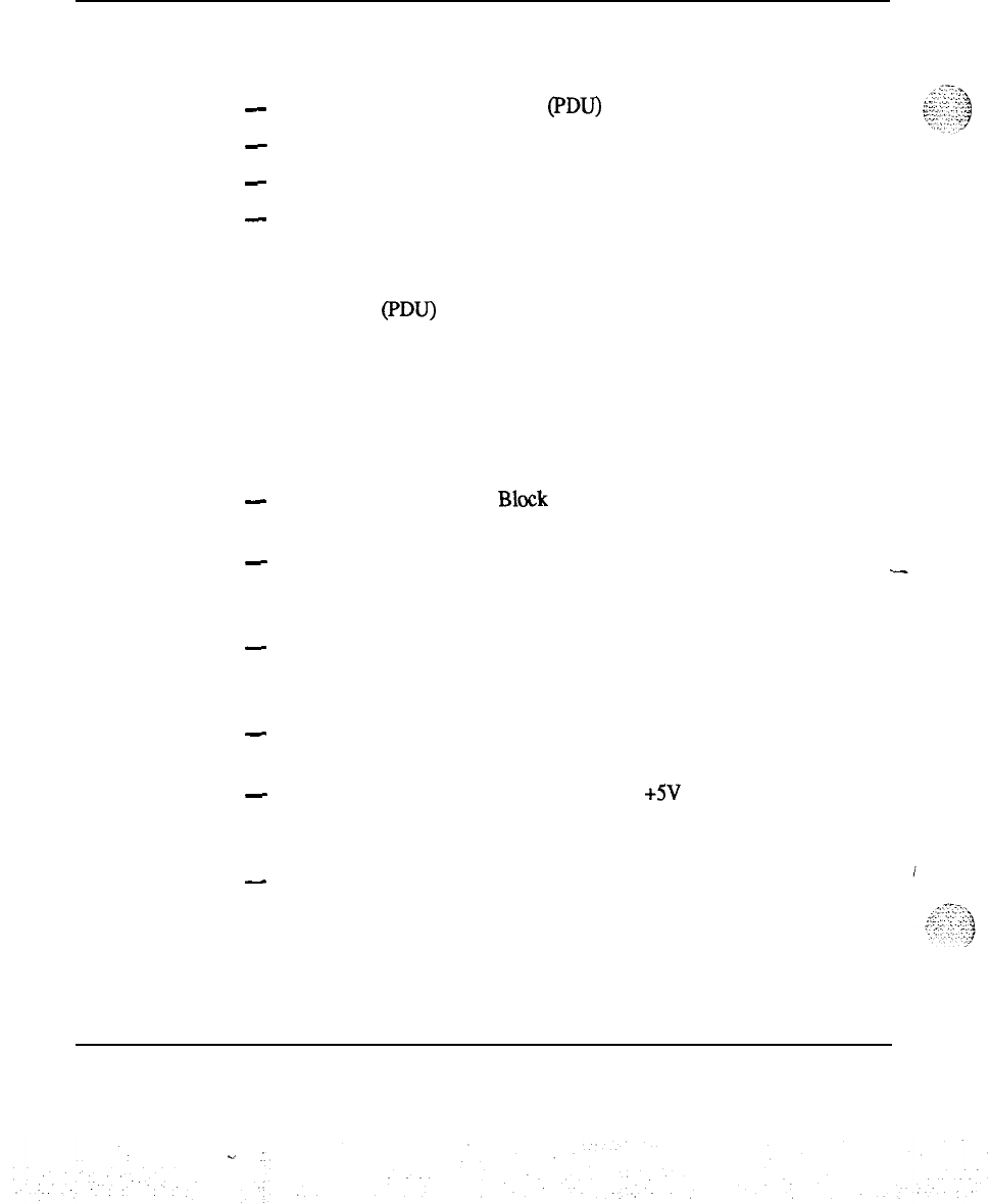
20 DC power system description
Internal power distribution
Figure 9 shows the internal DC power distribution elements:
-
Pedestal Power Distribution Unit (PDU)
-
Module to Module Harness
-
Module to Backplane Harness
-
DC Power Converters
The power cables enter the Pedestal and connect to an internal terminal block
located in the pedestal. From there, the DC voltage enters the Power
Distribution Unit (PDU) which has five circuit breakers, one for each of the
four modules and one for the cooling fans. The System monitor runs off a
DC-to-DC converter. Module to Module distribution brings individual DC
power to each module similar to AC distribution.
Pedestal Power Distribution Unit (PDU)
The Pedestal PDU provides the following:
-
The Field Wiring Terminal
Block
provides a connection point in the
bottom of the Pedestal for the external wiring.
-
The Circuit Breakers provide individual Module protection devices for
Module overload currents and a single trip function to shut down the
Stack in the event of a thermal overload.
-
The Internal Terminal Block provides individual power hand-off points so
that each Module is independently powered from the Pedestal in order to
minimize wire size.
-
The Power/Signal Harness provides the Power and Signal connections in
the PDU for the Blower Unit and System Monitor.
-
The System Monitor Power Supply (a small +5V DC-DC Converter)
provides power to the System Monitor, even when all of the Circuit
Breakers have been tripped.
-
The Output Power Harness provides the independent power connections
from the Pedestal to the Module above it.
Power engineering 553-3001-l 52
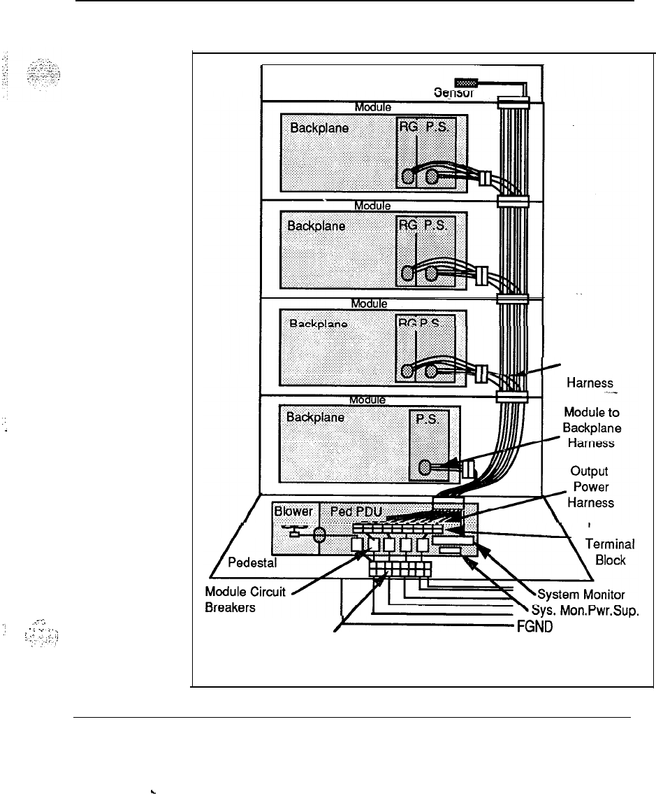
.:
.
.
..-.:.
:/
--..
>
;
:
;
:
::...:
..,.
Ii
:
,,.‘/
DC power system description 21
Figure 9
DC internal power distribution
I
Top Cap
I
Module to
>
Module
Internal
Field Wiring Terminal
Y
FGND
Block
Power engineering 553-3001-l 52
.
.

22 DC power system description
Module to Module Harness
The Module to Module Harness provides the following:
-
The Module Feed provides the independent power feed to the Modules
above itself.
-
The Module Harness Feed provides the power feed to the Module
backplane Harness.
Module to Backplane Harness
The Module to Backplane Harness provides the power feed to the backplane
connector which in turn provides power to the DC Power Converters.
DC Power Converters
Three different DC Power Converters provide power to the Peripheral
Equipment, Common Equipment and Common/Peripheral Equipment
Modules. The Ringing Generator provides ringing voltage for Peripheral
Equipment Modules.
At each shelf, -48 V is received through the backplane distribution harness
and converted to the necessary voltages for the individual module. Switches
are located on each converter to provide for safe operation and easy
maintenance. With separate Module breakers located in the Pedestal PDU, the-
Module Power Distribution Unit (MPDU) is not necessary.
Power engineering 553-3001-l 52
C.
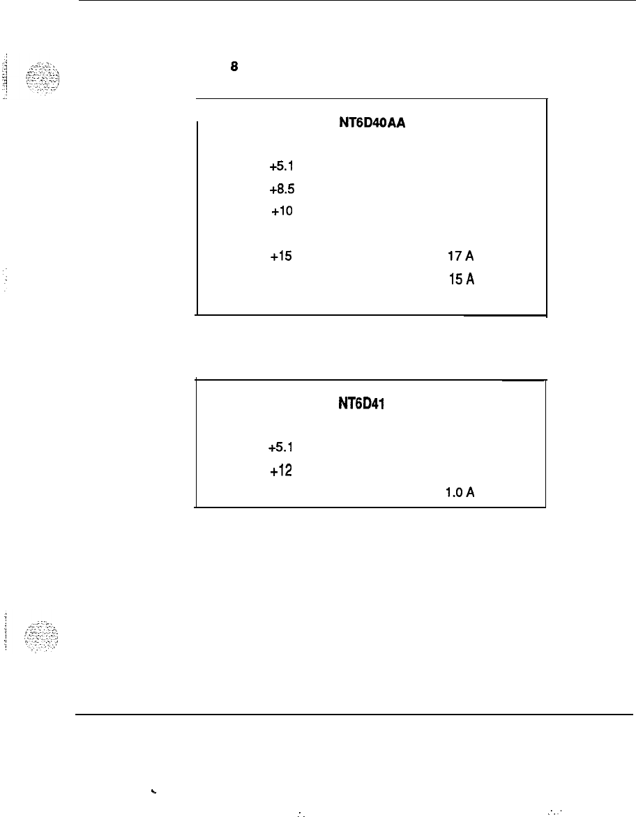
DC power system description
23
The output voltages and currents of the power converters are listed in Tables 8
through 11.
Table 8
Peripheral Equipment Converter
I
Output v
+5.1
v
+8.5
V
+lO
v
-10 v
+15
v
-15 v
-48v
NT6D4OAA
Output A
28A
4.0 A
0.5
A
0.5
A
17A
l5A
7.7
A
Table 9
Common Equipment Converter
I
NT6D41 AA
output vOutput A
+5.1
v
60
A
+12
v
3.5
A
-12v
l.OA
Power engineering 553-3001-l 52
.
.
:
.
.
.:
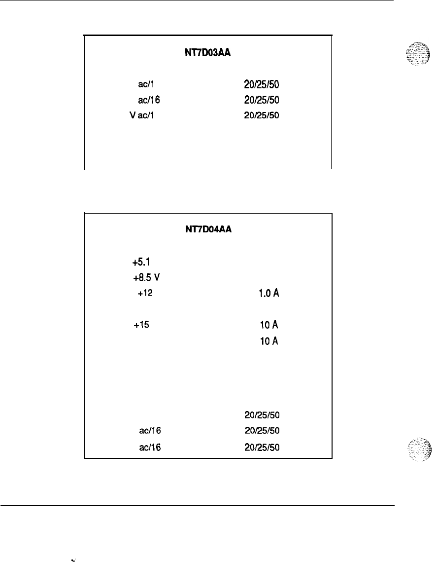
24 DC power system description
Table 10
Ringing Generator
Nl7W3AA
Output VNA Output. F
70V
act1
6VA
20/25/50
Hz
80 V
acfl6
VA
20/25/50
Hz
86
V
at/l
6VA
20/25/50
Hz
output voutput A
-150 v 0.200 A
Table 11
Common/Peripheral Equipment Converter
output v
+5.1
v
+8.5
V
Nl7DO4AA
output A
5aA
2.5 A
+12
l.OA
-12 0.75 A
+15
v
1OA
-15 v
1OA
-48V 4.75 A
-150 v 0.2 A
Output VIVA
70 V acll6 VA
80 V
acll6
VA
86 V
acil6
VA
Output F
20/25/50
Hz
20/25/50
Hz
2Ol25150
Hz
Power engineering 553-3001-152
v
DC
power system description 25
External power distributioh and grounckonnections
The power plants shown in the following ‘figures are typical but there are
many variations possible for the item labeled “Rect/Dist” It could be existing
customer equipment or a system that Northern Telecom either supplies or
recommends. In any case, the rectifier and
@tribution
equipment are
required; the batteries are optional.
Note:
The NT6D52 Switched Mode Rectifier is a QRF12 mounted
within an EM1 enclosure.
In all cases it will be necessary to carefully plan ahead. Refer to the chapter
entitled “Engineering and configuration guidelines.”
Figures 10 through 13 also show the important grounding connections and the
use of the IGB (Insulated Ground Bus). For a general discussion of the
grounding philosophy, see “System grounding.”
General notes for DC figures
Permanent Connection of the rectifier(s) to Branch Circuit
When conduit
or a raceway is used it should be metal and regardless of the
typejt
must
contain an insulated ground wire (green), 6 AWG or larger.
Cord Connection of the rectifier(s) to Branch Circuit
A separate safety-
ground is
always
required when removable line cords are used for the
following reasons:
-
a telephone wire could contact AC elsewhere in the building while the cord
is unplugged (during installation)
-
to minimize hazards from lightning transients when unplugged
-
to minimize the effects of stray grounds (pedestal to floor RS-232 links
to
monitors) during normal operation
This additional safety ground must be 6 AWG or larger, preferably insulated
and must be connected from the pedestal Frame Ground to the Logic Return
Equalizer (with Northern Telecom power units). With customer provided
power, the safety ground must go directly to the ACEG. See Figure 12.
It is preferred that the outlets for rectifier powering be isolated according to
NEC 250-74
and 384-27 (Exception 1).
Power engineering 553-3001-l 52
-.
..:
‘.
. .
I
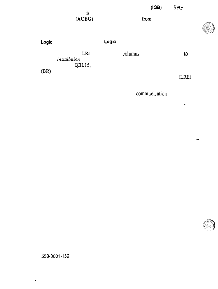
26 DC power system description
Single Point Ground (SPG) and Isolated Ground Bus (lGB) The
SPG
in
this grounding scheme
is
the AC Equipment Grounding bar in the AC
distribution panel
(ACEG).
If
this bar is insulated
from the
distribution panel,
as is recommended, then it is referred to as an IGB. In the following figures,
the preferred methods for using an ACEG and an IGB are illustrated.
Logic Return (LR) wiring and Logic Return Equalizer (LRE) location
When multiple columns are present or where links will be made to existing
SL-1 equipment, the LRs of the different coiurnns must be joined. Refer
to
System insfuflation procedures
(553-3001-210). When using a Distribution
Unit such as the
QBLlS,
QCA13 and most others, the existing Battery Return
(BR) bus will serve double duty as the LRE. The logic return wire must be
run in conduit to the LRE. A 6 AWG conductor then connects the BR (LRE)
to the ACEG in the AC panel.
This single point equalizing is required because communication between
modules that are not in the same physical line-up would put small amounts of
DC on the AC (green wire) ground. Residual AC voltages would be
‘-
superimposed (longitudinally) on the logic. There are a only a few volts of
common mode rejection capability on these lines. Refer to “System
grounding.”
120 V receptacles and cord or conduit items in the figures are used as
required.
-.-
Junction Box A junction box close to the pedestal may be required
depending on the wire size required between the pedestal and the distribution
point. See the chapter entitled “Power conductors.”
Power engineering
553-3001-152
s.
:
.
.

.
.
. .
:
.
._.-
.
,-“.,
‘.
c;
;
,,~
.._:.:.
,~,:
,’
DC power system description 27
Figure 10
Multi-column distribution with NT6D52 and ‘QBLl5
AC in
NT7Di 2 rack
EJofe
1: This is a 3 conductor cable enclosed in conduit. BR(+) and LR go to the
positive bus bar in the QBL15; BAT (-) connects to the appropriate fuse in the
QBL15.
hlofe
2:
May be run independently to ACEG.
AC service
6 AWG BWLR ref
AC conduit
receptacle(s)
Power engineering 553-3001-l 52
.
.
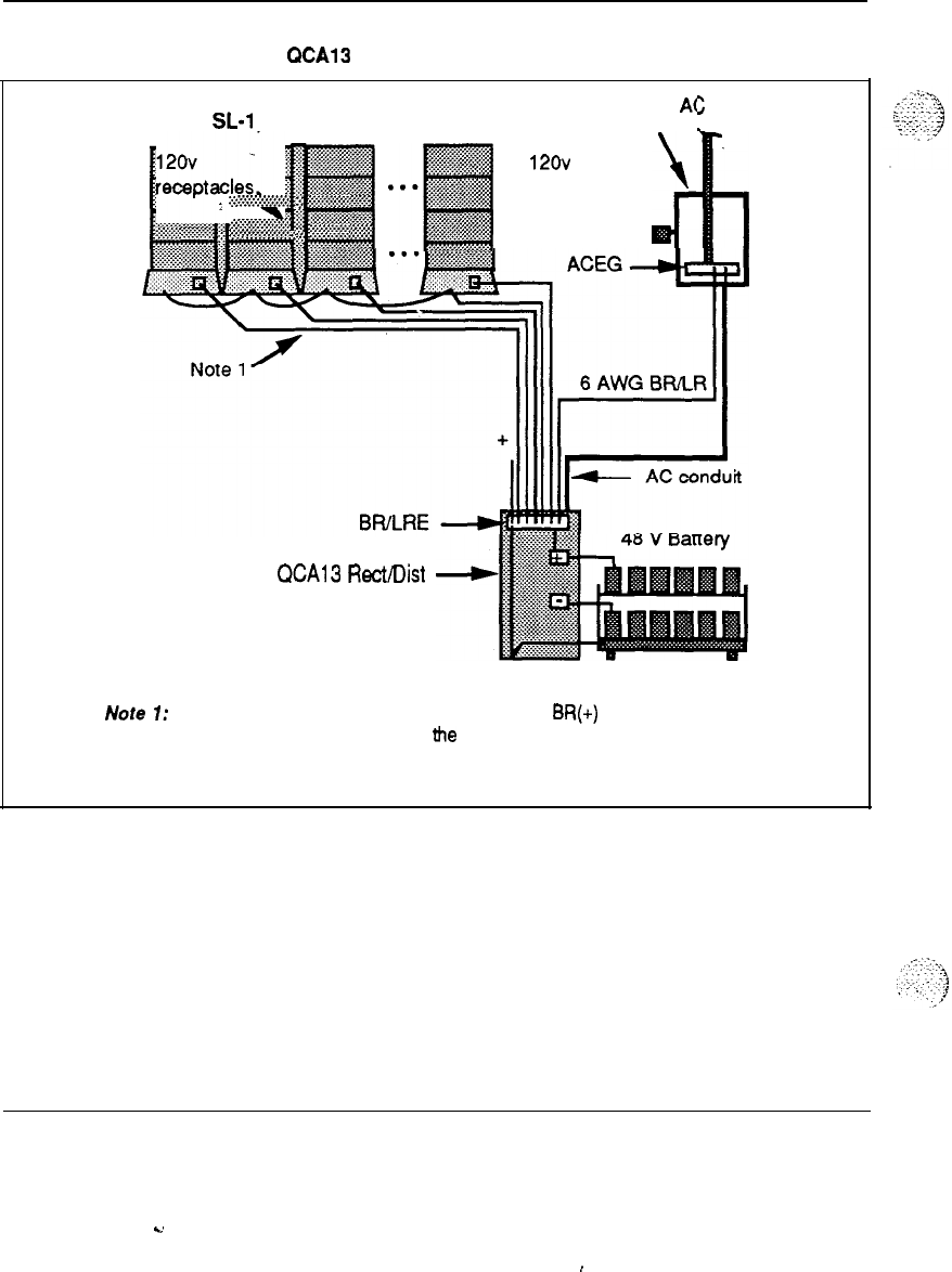
28 DC power system description
Figure 11
Multi-column distribution with
QCA13
A(
AC service panel
SL-1
System
>
in
:.:.:.:.:.:~<:~
y
::$c?~::~.:~&
:$$$$ggg
::
. . . .
.,.,.......,:,
2‘
,,:,.
y
;;;$@
#
. . . . . . . . . .
:*.:.:
. . . . . . . . . . . . . ,:
.:.
,_
y
:~&*:+x
~
$j$g$p$
120”
.
re-pt=ies\
:
:j:i-:i:.:.:.:.:.:.:.:.:
:::
#g$.J.<g..:.:,..:.
w<e::.:.:
<.
:*
.:.~.:.:.~.,.~.,.,.,.~.~
,:,
i%?cw~~
.~.>,>:.:.:y,~,~~.~
:.:
‘~.~
WA13
RectIDist
cabinet
Note 1: This is a 3 conductor cable enclosed in conduit. BR(+) and LR go to LRE;
BAT(-) connects to the appropriate fuse in the QCA13.
Power engineering 553-3001-152
..d
,

DC Power system description 29
Figure 12
Multi-column distribution with
QBLl2
customer power
SL-1 System
AC in
.A...... . . . .
. . . . . . . :. . . . . . . . . <
A....
, .
..A
. . ..:. . . . . . . .
y
7
AC service
fjanel
.
.
.
I
120v
receptacle+
ACEG
4
AC conduit
Customer: Rectifier/Battery plant
Note 1: This is a 3 conductor cable endosed in conduit. BFi(+) and LR go to the
QBL12 then go to a customer provided LRE. BAT(-) connects to the appropriate
fuse in the QBL12.
Note 2: In the case of customer provided power, the SL-1 frame requires a direct
connection to the ACEG. Additionally, the customer must make the connection
between the positive bus bar and the ACEG.
..,
..A
. .
.
.
.i.
-.
.._.., r
.
.
.
.
c:-.
:
:-.:;*.
1
.
.
-.
.
.
.
.,
.;.:p;
.,
Power engineering 553-3001-l 52
I
C’
30 DC power system description
Figure 13
Extended systems
SL-1 System
120v
’
m
receptacles
W
AC service
rianel
T
,.-a-
7
ACFr,
-1
Note 1
-tIIIII
X-1
\I
~~
BR/LRE
(Ground
-
]
window)
F
a
11111
FiAWr,
11
-RecVDist cabinet
(WA1
3)
Note 1: This is a 3 conductor cable enclosed in conduit.
BR(+)
and
LR go
to
LRE; BAT(-) connects to the appropriate distribution fuse.
Note 2: May be run independently to
ACEG.
Power engineering
553-3001-152

31
System grounding
Proper grounding is essential to system operation. The SL-1 system requires
a single-point ground. Proper grounding is required for trouble-free operation
and for the safety of personnel. The DC resistance of the conductor joining
the SL-1 system system ground reference to the main building ground should
be as close to zero as possible. The maximum total resistance from an SL-1
System pedestal to the main building ground cannot exceed 0.5 ohms, The
external earth ground should meet NEC/CEC requirements.
Lack of proper grounding can result in an installation that is not protected
from lightning or power related faults and does not provide an optimum path
for residual AC or DC currents. This may cause:
-
Hazards for personnel working on or using the equipment
-.-
-
Various service interruptions
-
Excess noise on analog circuits
-
High bit error rate on digital circuits
Note:
All voice and data lines leaving or entering the SL- 1 system
which mn external to the building must have fault protectors that connect
directly to earth ground. This is not the ground being discussed here.
;
,:
_
:.:::
j::.y.;.
j
:
-y..;
Power engineering 553-3001-l 52
.
.
32 System grounding
-
Single Point Ground
This system does not, by design, require an isolated AC ground (IG) system
(although local codes may require it). The system does require a single point
ground (SPG) system. The SPG is needed because several conductors are
used as returns. These include battery returns (BR) and logic returns (LR).
Logic return is the name used to bring this particular return out of the pedestal.
But,
internally, several other internal ground returns (also called analog
ground or talk battery return) are connected to the LR.
In its simplest form, the SPG may be the Isolated Ground (IG) bus or AC
Equipment Ground (ACEG) bus in the AC panel. This can be implemented if:
-
The electrical code allows isolated grounds (as per NEC 384-27 exception
1. in the USA).
-
This ground bar located in the AC panel has sufficient terminal points.
-
There is no non isolated communication links to existing PBX or other
communication equipment.
Using an Isolated Ground bus is often a lower cost method but is not allowed
by all telcos and may be prohibited by local ordinances. An alternate ground
will be needed where an AC panel with an IG bus cannot be provided. When
an alternate SPG is used or where there are too many return conductors to
--
terminate on an IG bus in the AC panel, one or more ground collector nodes
may be required. A grouping of like returns, prior to attaching to the SPG
window is preferred to many long runs of smaller diameter cable. See “List
of terms” for an explanation of these ground nodes.
LRE
A Logic Return Equalizing bus (copper plate or bar) is needed on multi-
column systems where the IG bus in the AC panel is:
-
not being used because of local electrical code requirements
-
too far removed from the pedestals being served
-
too small (insufficient connection points)
-
not expected to be the best ground available (for example, it is known to be
noisy or there is a more direct ground connection)
.d.T.
,>...
.,....
1
‘,
.
,:,
When the LRE function is served by something like an ACIG bus or the LRB
.y:.
2:
_.
+-
-3
..
‘:
+.
bus is also used to terminate system returns other than logic returns, there can
be confusion over terms. In general, large spread out systems require a star-
Power engineering 553-3001-l 52

System grounding 33
like ground system with local ground references like the LRE and ACIG
coming together at a main ground window, while small systems tend to use a
ground bar or plate for several purposes and it ends up taking on the name of
it’s primary function.
Additional requirements
The following must also be observed to implement the single-point ground
concept:
-
All ground conductors must be identified in accordance with local codes
and terminated in a manner that is permanent, resulting in low impedance
connections.
-
Terminations should be accessible for inspection and maintenance during
the life of the installation.
-
All grounding conductors must be continuous with no splices or junctions
and tagged,
“D
O
not remove or disconnect.” They
should also be
insulated against contact with foreign grounds.
I.
-
Grounding conductors must be no-load, noncurrent carrying cables under
normal operating conditions.
-
The use of building steel as part of the ground system (in the series path)
is not recommended. However, in a steel-framed building, the SL-
1
System main ground interface must be referenced to structural steel
-
(either on the same floor or within one floor) in order to minimize
lightning hazards.
Isolated ground topology
A dedicated Isolated Ground (IG) bus bar is required with this method. This
IG bus is located in the ac panel and serves as the ground window. It is used
for all AC (green wire) grounds as well as logic returns. It also
accommodates a conductor which references to the (+) battery bus in a DC
system. An alternate form of this isolated topology is to use one or more
isolated equalizing bars external to the AC panel but which connect to ground
exclusively through the AC IG bus.
Isolated orange outlets are required (as per h!EC 250-74 exception 4).
Grounding conductors shall be routed with the phase conductors (Article
300-20). All ground wiring for IG receptacles are to be terminated on the
dedicated IG bus according to applicable codes (complies with NEC 384-27).
Power engineering 553-3001-l 52
.
.

34 System grounding
Non-isolated ground topology
In a non isolated system the AC equipment ground (ACEG) connects to the
metal panel, and the associated conduit may also contact various structural
metal. This ground alone is not adequate for the SL-1 system. A true SPG
system will not be possible, but a dedicated ground conductor which connects
to the main building ground is then used for the main ground window to
terminate logic returns and reference the (+) battery bus. Frame grounds will
connect to the ACEG.
Power engineering
553-3001-152
c.
Operating power requirements
Introduction
This section contains:
-
power consumption data for both circuit packs and full modules
-
guidelines and methods to help you determine total system power
requirements, for both AC and DC systems
I.
Circuit pack power consumption
The power consumption of all currently-supported peripheral equipment
circuit cards is given in Tables 12 and 13.
All of the power data is stated in Watts for simplicity, with conversion to-AC
or DC current occurring only at the last step in the calculation. In addition, all
of the stated numbers have
already
taken the average efficiency of the Module
power converters into account.
The traffic assumptions used in these figures are 25% active (9 CCS) for
digital and analog lines, and 100% active (36 CCS) for trunks. Note that the
power consumption of digital line cards does not vary greatly with traffic, as it
may with analog line cards.
j
_
.“..
., 1..
^.
_
.,
c--.-..a,
,_
:
._.
.:.
.,._
.,::
;:
Power engineering 553-3001-l 52
.
.
.:
..:
.,
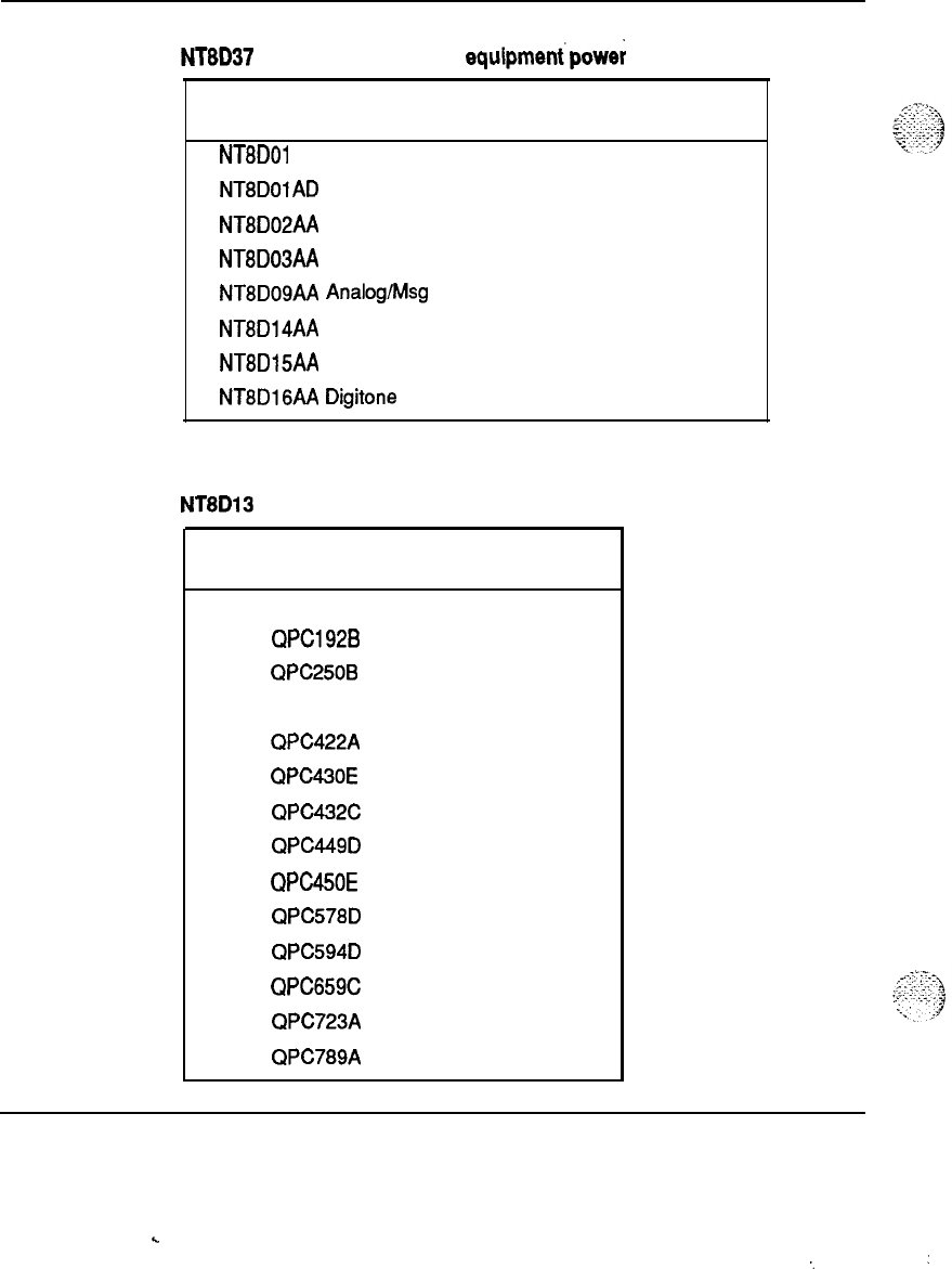
36 Operating power requirements
Table 12
NTBD37 Intelligent peripheral equipment’powe; consumption
Circuit pack
NT8DOl AC Controller-4
NT8DOlAD Controller-2
NTBD02AA Digital LC
NT8D03AA Analog LC
NT8DOSAA Analog/t&g Waiting LC
NT8Dl4AA
Universal Trunk
NT8D15AA E&M Trunk
NTBD16AA Digitone Receiver
Typical
power (Watts)
32
32
28
20
20
36
34
7
Table 13
NT8D13 Peripheral equipment power consumption
Typical
Circuit pack power (Watts)
QPC71 F 2.5
QPCl92B 12.0
QPC250B 2.5
QPC297
7.1
QPC422A 10.9
QPC430E 14.8
QPC432C 10.2
QPC449D 15.6
QPC450E
7.0
QPC578D 24.6
QPC594D 32.8
QPC659C 40.4
QPC723A 14.8
QPC789A 26.4
Power engineering 553-3001-l 52
.
.
‘. :
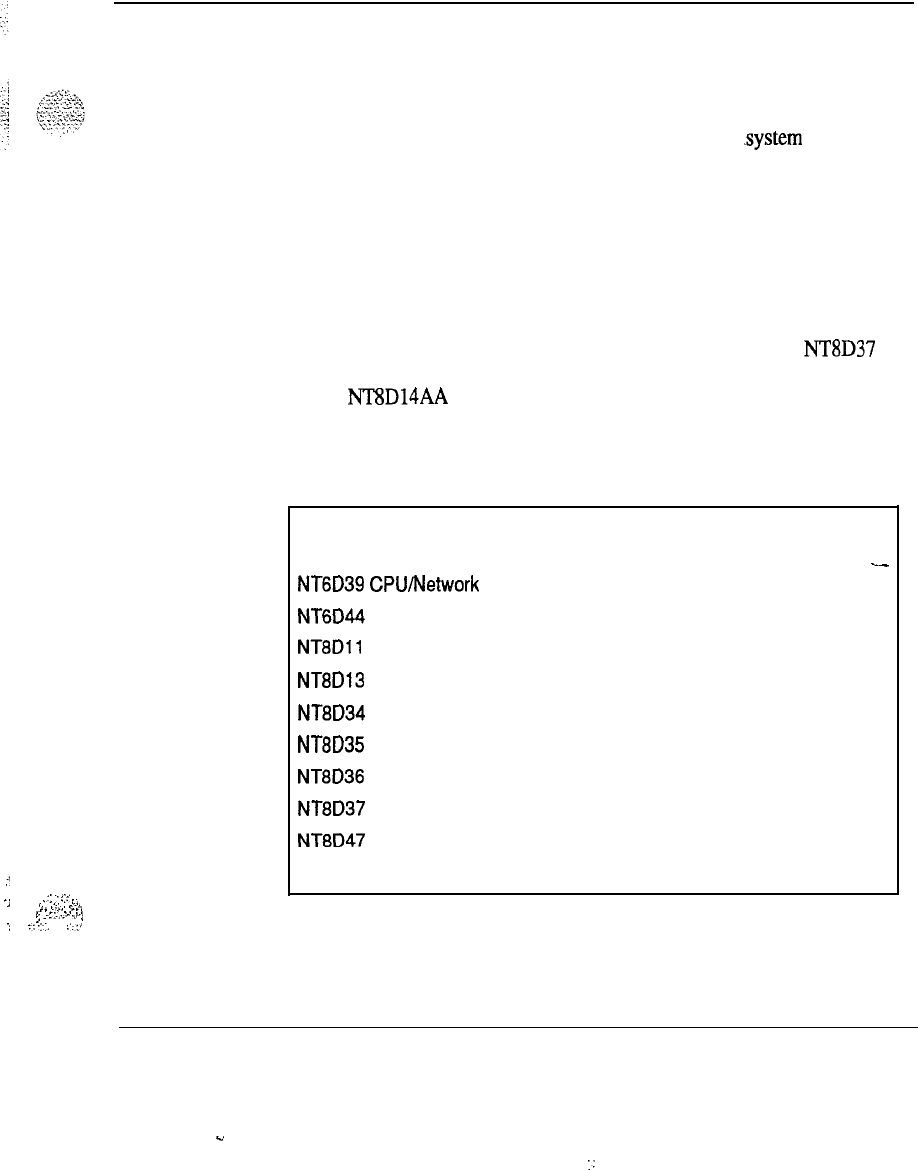
i
Operating power requirements 37
i
‘i
.::
.-::<
.
.
,
:..
i...
i
_.
..~..
.__,
,.
,~.
.“.
_I
!
.
.
.;..
.L.
1
,
,
.
:
::.:.
..:,
Module power consumption
The typical and worst case power consumption data for each fully configured
module are shown in Table 14.
The “typical power” data is generally adequate for use in .system power
engineering calculations, since it is representative of most systems with
Modules fully loaded (configured) with cards, and under moderate traffic
conditions.
The “maximum power” dam is shown for reference and planning purposes
when needed, and was calculated for each module based on a fully-loaded
card cage, in the worst-possible operational configuration (in terms of power
consumption), with each card consuming typical power, plus 10% added
margin. For example, the maximum power consumption for the NT8D37
Intelligent Peripheral Equipment Module was based on a configuration of
sixteen NT8D14AA Universal Trunk cards, all under 100% traffic conditions,
along with a Controller card and additional power margin.
. .
Table 14
SL-1 System UEM power consumption
Power consumptbn (Watts)
Module
Typical
Maximum
NT6D39
CPUMetwork
400
420
_-
NT6D44 Meridian Mail
400 450
NT8Dll
Common/Peripheral Equip. 500 690
NT8D13 Peripheral Equipment
400 575
NT8D34 CPU
300 335
NT8D35
Network
300 325
NT8D36
Junctor
0 0
NT8D37 Peripheral Equipment
550 720
NT8D47 Remote Peripheral Equipment
300 350
Pedestal (Blowers)
50 80
Power engineering 553-3001-152
.u
.:

38 Operating power requirements
System power calculation guidelines
The SL- 1 system was designed so that there would be no restrictions as a
result of power or thermal limitations. In other words, any card can go in any
slot, and all modules can be filled to capacity with any (logically) valid
combination of cards, with no engineering rules.
.-i’
_
Two system power calculation methods are shown below. For configuring
rectifiers as well as configuring reserve power, it is recommended to use
typical current drain values.
“Wired-for” method
This method is based simply on the number of modules and columns in the
system, regardless of how many cards are initially equipped. This method will
insure that the external power supply will have adequate capacity under all
conditions and all possible growth scenarios within the modules installed.
Using Worksheet A, simply enter the quantity of each module, multiply by the
power per module, and add up the total power. To calculate the current drain,
divide by the nominal voltage. AC current is calculated by dividing 230 V ac
nominal. DC current is calculated by dividing 52 V dc nominal. Both typical
and maximum current may be calculated.
“As-equipped” method
.-
This method provides a way to tailor the system power supply more closely to
the actual power consumption of the system as installed. The method is to
take the Common Equipment power consumption as a constant, then add the
power consumption for the actual PE cards equipped (or planned) from Tables
12 and 13.
Using Worksheet B and C, enter the quantity of each circuit pack, multiply by
the power per card, and add up the total power. Enter these numbers into
Worksheet D, and follow the same steps used above. AC current is calculated
by dividing 230 V ac nominal. DC current is calculated by dividing 52 V dc
nominal. Both typical and maximum current may be calculated.
Notes on AC vs. DC systems
To calculate current drain at values other than the nominal values given in the
worksheets, simply divide by the desired nominal value. For example,
208
V ac or 42 V dc.
Power engineering 553-3001-152
.
.
.‘..’
::

Operating power requirements 39
For calculations normally done in apparent or complex power (such as AC
wire and panel size, UPS rating for AC reserve power, etc.), simply divide the
total real power (in Watts) by the typical system power factor of 0.6 to obtain
the complex power (in VA).
Power engineering 553-3001-l 52Power engineering 553-3001-l 52
. .
.
.
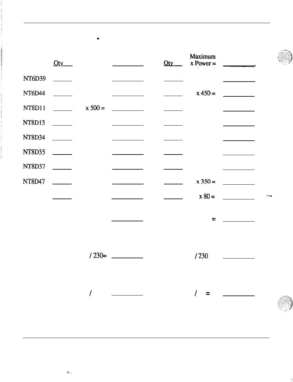
40 Operating power requirements
Worksheet A
System power consumption
-
“Wired for”
Typical
Module
Otv
x Power =
NT6D39
x400=
NT6D44
x400=
NT8Dll x500=
NT8D13
x400=
NT8D34
x300=
NT8D35
x300=
NT8D37
x550=
NT8D47
x300=
Pedestals x50=
Typical Power (Watts) =
.
AC System Current Drain (Amps ac)
Nominal: Typical Power
/
230=
DC System Current Drain (Amps dc)
Nominal: Typical Power
/
52 =
x420=
x450=
x690=
.
x 575 =
x 335 =
x325= .
x720=
x350=
x80= .-
.
Max. Power (Watts) =
Max. Power
I230
=
.
Max. Power
/
52 =
Power engineering 553-3001-152
. .
::
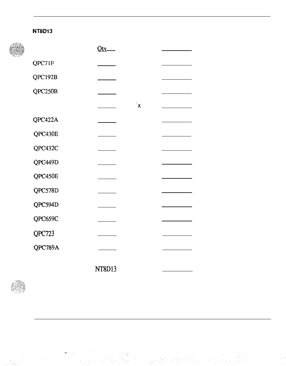
Operating power requirements
41
Worksheet B
NT8D13
Power calculation
Circuit Pack
QPC71F
QPC192B
QPC250B
QPC297
QPC422A
QPC430E
QPC432C
QPC449D
QPC450E
QPC578D
QPC594D
QPC659C
QPC723 A
QPC789A
Qtv
x Power =
x 2.5 =
x 12.0 =
x 2.5 =
-x
7.1 =
x 10.9 =
x 14.8 =
x 10.2 =
x 15.6 =
x 7.0 =
x 24.6 =
x 32.8 =
x 40.4 =
x 14.8 =
x 26.4 =
Total NT8Dl3 Power (Watts)=
Power engineering 553-3001-l 52
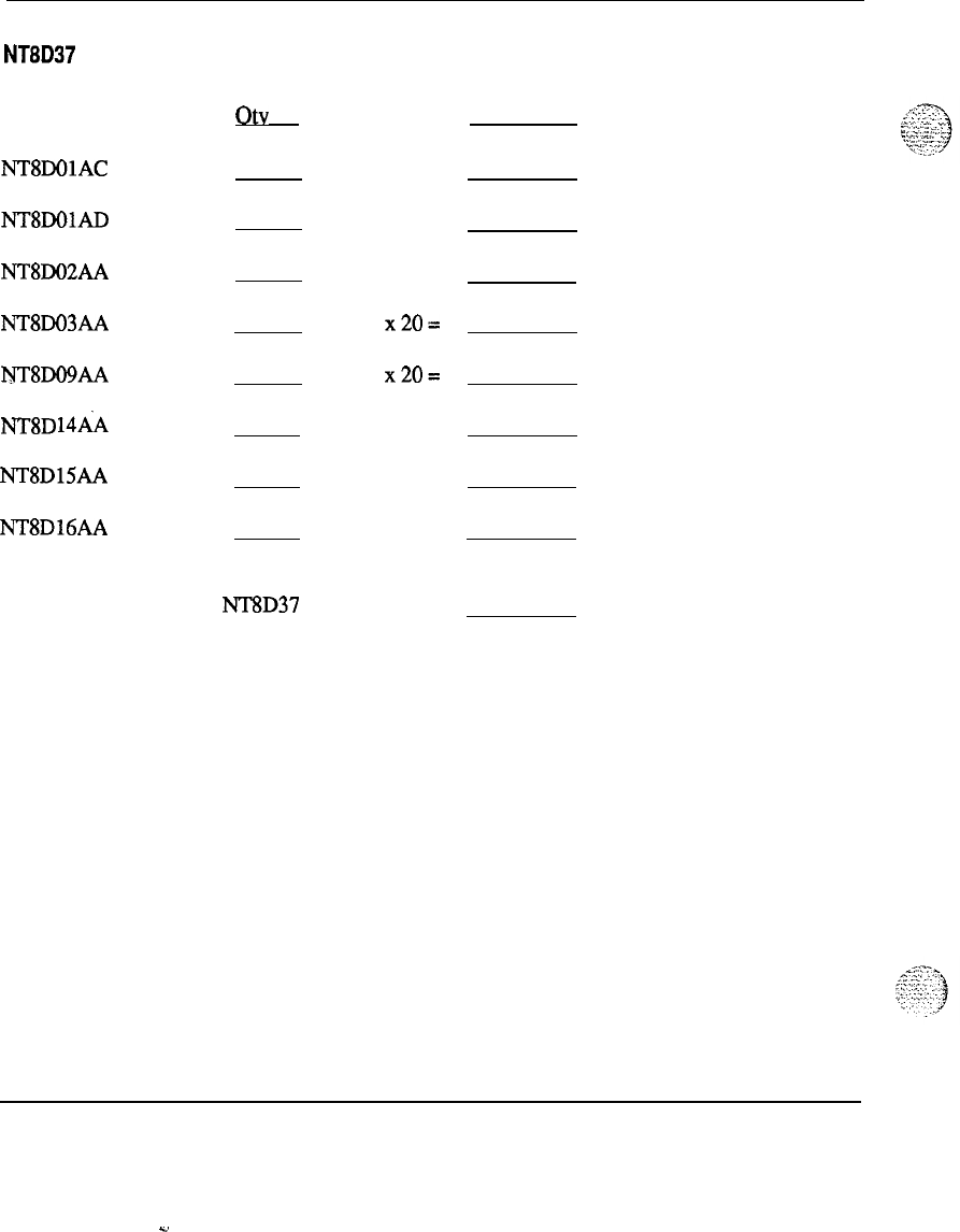
42 Operating power requirements
Worksheet C
NT8D37 Power calculation
I
Circuit Pack
otv
NT8DOlAC
NT8DOlAD
NT8DO2AA
NTaDo3AA
IYT’8DO9AA
NT8D
14ti
NT8DlSAA
NT8D16AA
x Power =
x32=
x32=
x28=
x20=
x20=
x36=
x34=
x7=
.
Total NT8D37 Power (Watts)=
Power engineering 553-3001-l 52
C.
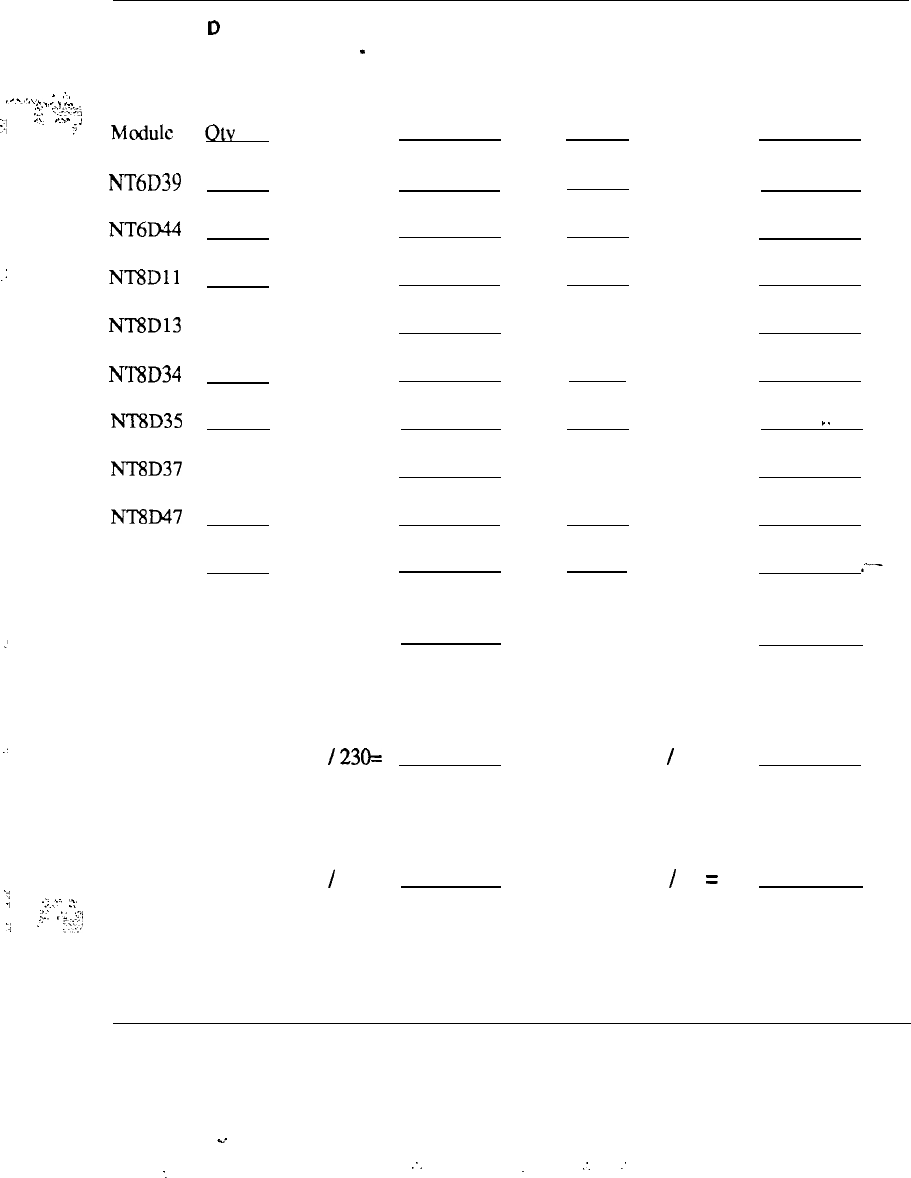
Operating power requirements 43
Worksheet
D
System Power Consumption
-
“As equipped”
.
.
:,
.-...\..
.
.._._
.
.
. .
;‘:
,“.z;;‘23
._I
_..
,..,_
I
Typical
f
Mod&
Otv
x Power =
NT6D39
x400=
NT6D44
x400=
.:
NTSDll
x500=
NTSD13 (from Worksheet B) =
NTSD34
x300=
NTSD35
x300=
NT8D37 (from Worksheet C) =
NTSD47
x300=
Pedestals x50=
_’
Typical Power (Watts) =
AC System Current Drain (Amps ac)
:
Nominal: Typical Power
/
230=
DC System Current Drain (Amps dc)
Nominal: Typical Power
/
52 =
‘:
.
.,
-::.:-.
.>.
.I
.::
:_
r;
:’
.:;;y;,,
otv
Maximum
x Power =
x420=
x450=
x690=
(from Worksheet B) =
x335=
x 325 =
(from Worksheet C) =
x350=
x80=
I.
.
.-
Max. Power (Watts) =
Max. Power
/
230 =
Max. Power
/
52 =
Power engineering 553-3001-l 52
.“.
:.
.
.
:.
:
-.

44 Operating power requirements
Upgrades to existing
itistallations
Total power consumption of an installed system can be determined in several
different ways. Two methods are listed below, in order of decreasing
accuracy.
Measure current drain for the complete installation over at .least a two-
.’
_
-’
-
week period under actual operating conditions. Determine peak current
drain from these measurements.
-
Measure idle (or near idle) current dram for the complete installation.
Estimate peak current drain by multiplying the number of idle amperes by
1.5.
When adding or upgrading equipment, use either of these methods to
determine existing current drain/power consumption. Use the guideline in this
document to determine the added power consumption. The existing power
plant may have to be replaced or its capacity increased to accommodate the
additional power requirements. As always, be sure to provide sufficient __
capacity to accommodate planned growth of the SL-1 System.
Upgrades to existing systems may use either AC or DC equipment. Existing
capacity, reserve power requirements, and available floor space are some of
the factors to consider.
Thermal considerations
The maximum power dissipation in the form of heat for each UEM is listed in
Table 15. These figures apply to both AC and DC powered systems. The
power figures listed here are different than those shown in previous tables for
system power consumption, since some of the power, especially for peripheral
equipment, is distributed out to the loops and sets and is not dissipated within
the UEM itself. Table 16 shows the maximum heat dissipation for some of
the external DC power equipment supplied by Northern Telecom.
Power engineering 553-3001-l 52
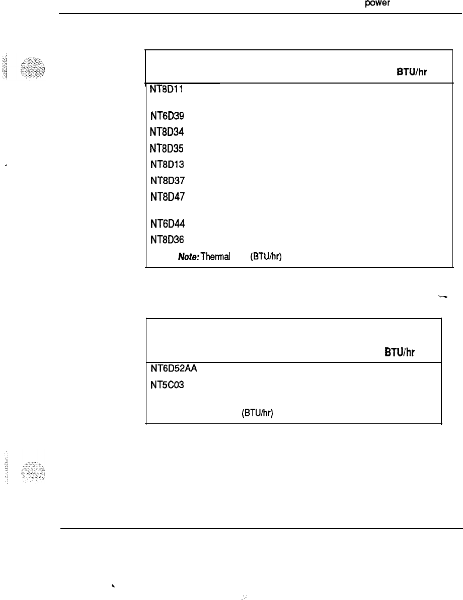
.
.
.
.
Operating
power
requirements 45
Table 15
SL-1 system heat dissipation
Module
Heat dissipation
Watts BTUlhr
NT8Dll
Common/Peripheral 450 1530
Equipment
NT6D39 CPU/Network 400 1360
NT8D34 CPU 300 1020
NT8D35 Network 300 1020
NT8D13 Peripheral Equipment 300 1020
NT8D37 Peripheral Equipment 425 1450
NT8D47 Remote Peripheral 300 1020
Equipment
NT6D44 Meridian Mail 400 1369
NT8D36 Junctor
0 0
Afote:Thermal load (BTU/hr) = Total power dissipation (Watts) x 3.4
Table 16
External power equipment heat dissipation
-
Heat Dissipation
Equipment Watts BTUlhr
NT6D52AA
30A Rectifier
200 680
NT5C03
50A Rectifier
290 990
Note: Thermal load (BTUIhr) = Total power dissipation (Watts) x 3.4
Power engineering 553-3001-l 52
.
.
:.:

46 Operating power requirements
.-
Power engineering
553-3001-152
.u
:
. .
r

47
Reserve power
Reserve power is available for both AC and DC systems. AC reserve power is
provided by a separate Uninterruptible Power Supply (UPS), installed in series
with the main system AC power feed. A UPS generally consists of a
combination battery charger (AC-DC converter) and inverter (DC-AC
converter), along with its associated batteries. The batteries may be internal or
external to the UPS unit itself.
I.
DC systems use the “traditional” telecommunications powering method of an
external power plant consisting of rectifiers (AC-DC converters) continuously
charging a bank of batteries, while the system power rails “float” in parallel on
the battery voltage.
--
AC reserve power
There are a wide variety of UPS vendors and systems available. Some of the
factors to consider when choosing a UPS are:
-
Input and output voltage and frequency range
-
Number and type of output receptacles
-
Regulatory and safely agency approvals
-
Efficiency, crest factor, and other performance considerations
-
Alarm and status indications
-
Battery recharge time
-
Backup time required
-Existing batteries or other power equipment at the site
-
Planned system growth
Power engineering 553-3001-l 52
48 Reserve power
UPS
sizing
Since power distribution for AC systems is provided on a per-column basis,
partial system backup is available for all system options, thus reducing
reserve power requirements. In other words, it is possible to back up all of the
common equipment, but only a portion of the peripheral equipment, reducing
both UPS and battery costs.
Even
if it is desired to back up the entire system, the per-column powering
allows the choice of provisioning one UPS per column, one UPS for the entire
system (all columns), or any combination.
In order to determine the
siie
of UPS needed, the total system (or column)
power requirements are first determined as in the previous section “Operating
power requirements.” The real power in Watts (W) is then converted to
complex or “apparent” power in Volt-Amps (VA) by dividing the real power
by the typical system power factor of 0.6. The UPS is then sized in terms of
its rating in VA (or kVA).
.
The sizing and provisioning of the UPS batteries will be determined by
following the specific instructions provided by the manufacturer of the UPS
that has been selected. The general approach, however, is to take the total
system power in Watts, divide by the UPS inverter efficiency, and convert to
battery current drain by dividing by the nominal discharge voltage of the
__
battery string. The battery current drain is then multiplied by the time that is
needed for the reserve power to operate to determine the battery requirements
in Amp-hours (A-hrs).
Recommended UPS vendors and models
As of the publication date of this document, the following UPS systems have
been tested by Northern Telecom and verified to work with the SL-1 system.
These vendors and models meet high standards of both quality and
functionality and are recommended to be used with the SL-1.
This list may change at any time in the future. Other UPS vendors may have
products which work fine with SL-1 systems, and the vendors listed here may
have other models and sizes that are also suitable. In particular, there are UPS
systems larger than 10
kVA
available that could be used with some of the
larger system option 71 configurations.
Power engineering
553-3001-152
.d
Reserve power 49
Table 17
Verified UPS systems
Vendor
Alpha Technologies
Alpha Technologies
Alpha Technologies
Best Power Technobgy
Best Power Technology
Exide Electronics
Exide Electronics
Exide Electronics
Exide Electronics
Exide Electronics
Exide Electronics
KVA
Rating
1
1.5
3
3
5
1.5
3
5
6
8
10
Battery
Voltage
48
48
48
48
48
120
120
120
240
240
240
Power engineering 553-3001-l 52

50
Resetve
power
The UPS systems are available directly from the recommended vendors. For
application assistance and direct sales information, the UPS vendor contacts in
the U.S. are listed below:
Alpha
Technologies, Inc.
3767 Alpha Way
Bellingham, WA 98225
(206) 647-2360
Fax: (206) 671-4936
Best Power Technology, Inc.
P.O. Box 280
Necedah,WI
54646
(608) 5657200
(800) 356-5794
Fax: (608) 565-2221
Exide Electronics
3201 Spring Forest Road
Raleigh, NC 27604
(9 19) 872-3020
Fax: (919) 878-1541
Power engineering 553-3001-l 52
C.
.,:
..’

Reserve power 51
Alarm Monitoring
^
A UPS to System Monitor Alarm cable is available from Northern Telecom
for
each
of the recommended UPS vendors. The alarm interface consists of an
“inverter on” signal to indicate that the commercial power is down and the
UPS is supplying power to the system, and a “summary
a@m”
signal from the
UPS to indicate a fault or alarm condition. The cables are listed below:
Table 18
UPS to System Monitor Alarm cables
UPS
vendor
Alpha Technologies
Best Power Technology
Exide Electronics
NT
part number
NT8D46AU
NT8D46A.I
NT8D46AQ
Installation
For UPS installation information, refer to the appropriate UPS vendor
installation manual. It is recommended, however, that a UPS bypass switch
be installed during the initial wiring if this switch function is not inherently a
part of the UPS itself. The UPS bypass switch allows for the PBX to be run
directly from commercial AC power while the UPS is taken off line during
installation or service, or during battery maintenance.
I1
CAUTION
Proper care must be taken when connecting the DC battery leads to
the UPS. A battery reversal at the UPS can result in severe damage
to the UPS.
A general block diagram of a UPS installation and associated wiring is shown
in Figure 14.
Power engineering 553-3001-I 52
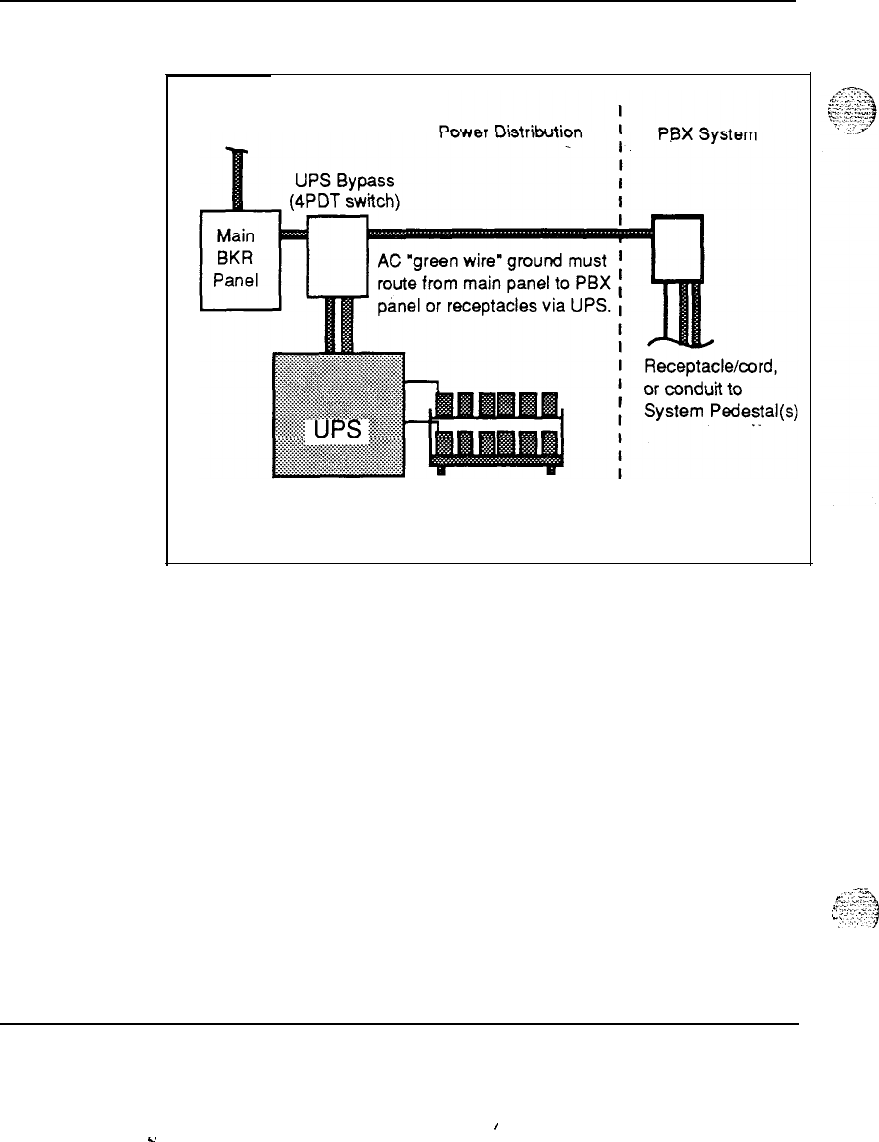
52 Reserve power
Figure 14
AC reserve power configuration
Commercial
AC power in
Optional external
I
Battery bank
I
”
f-z!.
;:c
.Y
2:
.‘
;.
-‘_..
.
^,.
:...I
_~
:-.
Power engineering 553-3001-152
I
-
Y
Reserve power 53
-
DC reserve power
Reserve power for DC systems can be provided simply by adding batteries to
the external distribution. The reserve battery capacity is determined by
multiplying the system current drain by the time that is needed for the reserve
power to operate. This will determine the total Ampere-Hour requirements of
the batteries. Refer to Worksheets A through D.
The following guidelines should be used in determining DC reserve power
requirements.
Current required
When considering battery backup you should know with reasonable accuracy
the total system power requirement.
For new installations, Northern Telecom provides the operating company
with data listing the total current drain for each configured system.
A
rectifier and distribution panel which has the capacity to meet these current
drain figures, and some added capacity to charge batteries can then be
selected. For existing instahations, the total current dram of an installed
system can be calculated in several ways. Refer to “Operating power
requirements” for more information.
The amount of reserve battery capacity depends on the system line size (load),
the time the reserve supply must last in the event of power failure, and the
battery end voltage.
Batteries
Reserve batteries for a DC powered SL- 1 system must meet the following
requirements as defined in Table 19.
Table 19
Battery requirements
Float
voltage Equalize voltage
w
09
Battery configuration cell String cell String
24 stationary cells -2.17 -52.08 -2.25 -54.08
23 sealed cells -2.25 -51.75 -2.35 -54.05
24 sealed cells -2.25 -54.00 -2.35 -56.40
Power engineering 553-3001-l 52
54 Reserve power
The float and equalization voltages defined in Table 19 are not an exact
requirement as long as voltages do not exceed -56.5 V. See Table 7 in “DC
power description.”
Not all sealed cells require equalization, but the equalization voltage can be
used for fast charging.
Batteries to be used with the SL-1 should be sized by using an end voltage of
4IV.
The noise limitations for a battery string are:
-
20 mV rms maximum ripple
-
32
dBmC
maximum noise
End cells and CEMF cells are not recommended because they are a noise
source.
I.
Other considerations
-Planned growth
-
Backup time required
-
Existing power system capability
-
Space and thermal conditions
-
Other equipment, lights, alarm systems
Power engineering
553-3001-152
s,

55
Engineering and configuration guidelines
Configuring the Meridian 1 power system requires attention to the following
points:
-
Both AC and DC-powering are available.
-
The AC power supply or DC-DC Converter that is used in a particular
module is virtually identical as far as external configuration purposes are
I.
concerned.
-
Equipment Module power and cooling criteria are also the same for both
AC and DC.
-
A wide variety of Uninterruptible Power Supply (UPS) systems are
available for AC-powered Meridian 1 systems that require reserve
poxer.
-
AC-powered systems, suited for those applications that do not need reserve
power, require no external power components and connect directly to
utility power.
-
All DC systems can be configured as complete systems, with rectifiers
provided by Northern Telecom. They can also be configured to connect
to customer-provided external power.
AC and DC powering schemes differ primarily in the external power
components (external, that is, to the Equipment Modules themselves).
The choice of which powering scheme to use is determined mainly by reserve
power requirements and preferences, and by the existing power equipment at
the site.
Power engineering 553-3001-l 52
56 Engineering and configuration guidelines
AC power architecture
^
The internal AC power system consists of the following main elements:
-
Pedestal Power Distribution Unit (PDU)
-
Module Power Distribution Unit (MPDU)
_
-
AC Power Supplies
No arbitrary selection of these components is required
-
they are included
automatically in the System functional determination process.
There are three different AC power supplies that provide power to all of the
common equipment, peripheral equipment, and combined common/peripheral
equipment modules, as well as a ringing generator that provides AC ringing
(and message waiting lamp voltages) when required for the peripheral
equipment modules.
No additional external power components are required for AC-powered
‘.
systems. Reserve power, if needed, is accomplished through the use of an
external Uninterruptible Power Supply (UPS).
Internal AC power equipment components
The following components are required to configure and AC powered system. _-
Common Equipment Power Supply AC (NT8D29AA)
The Common Equipment Power Supply AC is used in the Common
Equipment modules in AC systems. It is located in the first slot on the left in
the module labeled “CE Pwr Sup,“ and converts 208/240 V ac to +5 V and
f12
V dc, to provide all required voltages for CE and network circuit cards.
Configuration guidelines
One Common Equipment Power Supply AC is
used in each of the following AC modules:
-
CPU Module (NT8D34AA)
-
Network Module (NT8D35AA)
-
CPU/Network Module (NT6D39AA)
Power engineering 553-3001-152
-2
:
Engineering and configuration guidelines 57
:
i
:
,~
~
:,:..
.
.
.
.
._
.:
:
,.:
..,.
:. .
.
.
.
_:
,_
.,
Peripheral Equipment Power Supply
AC
(NT8DO6AA)
The Peripheral Equipment Power Supply AC is used to provide power to all
peripheral equipment modules in
J%
systems. It converts 208/240 V ac to
+5 V, +8.5 V,
f10
V, +15 V, and -48
V
dc voltages used to power peripheral
equipment logic cards and to supply “talk battery” to lines and trunks. This
power supply is located in the far left hand card slot labeled “PE Pwr Sup.”
Configuration guidelines
One Peripheral Equipment Power Supply AC is
used in each of the following AC modules:
-
Intelligent Peripheral Equipment Module (NT.8D37AA)
-
Peripheral Equipment Module (NT8D13AA)
Common/Peripheral Equipment Power Supply AC
(Nl7D14AA)
The Common/Peripheral Equipment Power Supply AC converts
2081240 V ac to +5 V, +8.5 V,
+_15
V,
+_12
V,
48
V, -150 V dc, and
86 V ac/20 Hz ringing voltages used to power peripheral and common
equipment, supply talk battery, and light Message Waiting lamps on 500/2500
sets. It is located in the left of the Module in the slot
labelled
“CE/PE Pwr
sup.
“
Configuration guidelines
One Common/Peripheral Equipment Power
Supply AC is used in each of the following AC modules:
-
-
Common/Peripheral Equipment Module
(NTSDllAR
or
NT8DllAC)
-
Remote Peripheral Equipment Module (NT8D47AA)
Ringing Generator AC (NT8D21AA)
The AC Ringing Generator AC operates from a nominal 208/240 V ac input
and provides selectable AC ringing voltage outputs superimposed on
48
V dc.
The frequency and voltage options are 70 V ac at 25/50 Hz, 80 V ac at
25150
Hz, and 86 V ac at 20/25. It also supplies -150 V dc message waiting lamp
500/2500 set applications. The Ringing Generator mounts in the PE modules
to the right of the Peripheral Equipment Power Supply.
Configuration guidelines
One Ringing Generator AC is used in each of the
following, when these AC modules support 500- or 2500~type analog sets:
-
Intelligent Peripheral Equipment Module (NT8D37AA)
-
Peripheral Equipment Module (NT8D13AA)
Power engineering 553-3001-l 52
.
.
58 Engineering and configuration guidelines
Pedestal
(NT8D27AB)
-
The Pedestal supports the column of Equipment Modules, and houses the
Power Distribution Unit, the Blower Unit, and a reusable dust filter.
The Field Wiring Terminal Block is mounted in the bottom of the Pedestal.
Configuration guidelines
-
One per column in AC systems
-
The Field Wiring Terminal Block is factory wired with the following
straps:
l
LRTN
-
FGND
Power Distribution Unit (NT8D53AB)
The AC Power Distribution Unit (PDU) distributes power to the entire
column. It is located in the rear of the pedestal. It houses a main circuit
breaker and the System Monitor.
Configuration guidelines One
per Pedestal/column in AC systems
Module Power Distribution Unit (NT8D58AA)
The NT8D56AA Module Power Distribution Unit (MPDU) protects the power
supply and distributes power within a module. It houses a single breaker and
_
is used in conjunction with the NT8D29AA Common Equipment Power
Supply AC.
Configuration guidelines
One per Module in AC systems
Module Power Distribution Unit (NT8D58AB)
The NT8D56AB MPDU protects the power supply and distributes power
within a module. It houses a single breaker and is used in conjunction with
the NT7D14 Common/Peripheral Equipment Power Supply AC.
Configuration guidelines
One per Module in AC systems
Module Power Distribution Unit (NT8D57AA)
The NT8D57AA MPDU protects the power supply and distributes power
within a module. It houses a dual breaker and is used in conjunction with the
NT8DO6AA PE Power Supply AC and the NT8D21AA Ring Generator AC.
Power engineering 553-3001-l 52
Engineering and configuration guidelines 59
Configuration guidelines
One per
hkdule’in
AC systems
:
.:
.’
:
The internal DC power system consists of the following main elements:
-
Pedestal Power Distribution Unit (PDU)
-
-
DC Power Converters
Like AC
systems,
there are three different DC power converters that provide
power to all of the common equipment, peripheral equipment, and combined
common/peripheral equipment Modules, as well as a ringing generator that
provides AC ringing (and message waiting lamp voltages) when required for
the peripheral equipment modules.
The external portion of DC-powered systems is generally referred to as the
power plant, and mainly consists of the rectifiers and distribution equipment,
as well as reserve batteries if required. For system options
21,51,
and 61,
Northern Telecom offers a power plant based on the NT6D52AA Rectifier,
with an output capacity of 30A per rectifier, along with a rectifier/battery
connection and distribution box
(QBLlS).
For system option 71, Northern
Telecom offers the QCA13 power plant based on the NTSC03BJ Rectifier,
with an output capacity of 50A per rectifier, with a total system capacity of
500A.
---
Customer-provided power is an option for all Meridian 1 systems. The
QBL12 Battery Distribution Box is available to connect a wide variety of
customer-provided power equipment to the system.
Power engineering 553-3001-l 52
60 Engineering and configuration guidelines
internal DC power equipment components.
The following components are required to configure and DC powered system.
Common Equipment Power Supply DC (NT6D41 AA)
.,-
-4
The Common Equipment Power Supply DC is used in the common equipment
c$;;j
Modules in DC systems. It is located in the first slot on the left in the module
labeled “CE Pwr Sup,” and converts -48 V dc to +5 V and +12 V dc, to
provide all required voltages for CE and network circuit cards.
Configuration guidelines
One Common Equipment Power Supply DC is
used in each of the following DC modules:
-
CPU Module (NT8D34DC)
-
Network Module (NT8D35DC)
-
CPU/Network Module (NT6D39DC)
Peripheral Equipment Power Supply DC (NT6D40AA)
..
The Peripheral Equipment Power Supply DC is used to provide power to all
peripheral equipment Modules in DC systems. It converts -48 V dc to +5 V,
+8.5
V,
+lO
V,
f15
V, and -48 V dc voltages used to power peripheral
equipment logic cards and to supply “talk battery” to lines and trunks. This
power supply is located in the far left hand card slot labeled “PE Pwr Sup”.
-
Configuration guidelines
One Peripheral Equipment Power Supply DC is
used in each of the following DC modules:
-
Intelligent Peripheral Equipment Module (lYIBD37DC)
-Peripheral Equipment Module
(NT8D13DC)
Common/Peripheral Equipment Power Supply DC
(NVDO4AA)
The Common/Peripheral Equipment Power Supply DC converts 48 V dc to
+5
V, +8.5 V, +15 V,
f12
V, -48 V, and -150 V dc voltages used to power
peripheral and common equipment, supply talk battery, and light Message
Waiting lamps on 500/2500 sets. The supply provides the following
selectable ringing voltage options: 70/80/86 V ac at 20/25/50 Hz. It is located
in the left of the Module in the slot
labelled
CE/PE Pwr Sup.
,-.-
”
,
.-; . .
‘.,I:.
”
:-:
A
Configuration guidelines
One Common/Peripheral Equipment Power
Supply DC is used in each of the following DC Modules:
Power engineering 553-3001-l 52
Engineering and configuration guidelines 61
-
Common/Peripheral Equipment Module
(NT8DllDC
)
-
Remote Peripheral Equipment Module (NT8D47DC)
Ringing Generator DC
(NT7D03AA)
The AC Ringing Generator DC operates from a nominal
.48
V dc input and
provides selectable AC ringing voltage outputs superimposed on -48 V dc.
The frequency and voltage options are 20/25/50 Hz and 70/80/86 V ac. It also
supplies -150 V dc message waiting lamp 50012500 set applications. The
Ringing Generator mounts in the PE modules to the right of the Peripheral
Equipment Power Supply.
Configuration guidelines
One Ringing Generator DC is used in each of the
following, when these DC Modules support 500- or 2500~type analog sets:
-
Intelligent Peripheral Equipment Module (NT8D37DC)
-
Peripheral Equipment Module (NT8D13DC)
.
Pedestal
(NT7DOSAA)
The Pedestal supports the column of equipment modules, and houses the
Power Distribution Unit, the Blower Unit, and a reusable dust filter.
The Field Wiring Terminal Block is mounted in the bottom of the Pedestal.
Configuration guidelines
One per column in DC systems
Power Distribution Unit (Nl7DlOAA)
The DC Power Distribution Unit (PDU) distributes power to the entire
column. It is located in the rear of the pedestal. It houses five circuit breakers
(one for each module and one for the Blower Unit) and the System Monitor.
Configuration guidelines
One per pedestal/column in DC systems
Module Power Distribution Unit
Not applicable to DC systems.
External DC Power equipment components
The following components are required to configure DC powered system.
Power engineering 553-3001-l 52
62 Engineering and configuration guidelines
Switched Mode Rectifier
-46VBOA
(NTGD5qAA)
Converts 208/240
V ac (nominal) to -48 V dc (nominal), with a 30A output.
Connects
to the system through the
QBLlS
Battery Distribution Box. Based
on QRF12.
,
Configuration guidelines System
options
21/51/61
(DC versions).
Generally one rectifier per every two fully loaded modules. Exact quantity
depends on system configuration and power requirements.
Rectifier Rack Assembly
(NT7D12AA)
This is a 19-inch open relay rack which is approximately 4’6” feet high.
It
supports up to three
NT6DZAA
Rectifiers.
Configuration guidelines System
options
21/51/61
(DC versions). One rack
per every three NT6D52AA Rectifiers, up to a maximum of two racks per
system.
-
_,^._
i.
.:x;::
.
“d”
.-a
.
.._.... 3
,.
.
...“_
.,..
..,...
:
“.‘“7
”
‘.’
”
,”
Power engineering 553-3001-152
,
C’
Engineering and configuration guidelines 63
Rectifier Bafflehloirnting Kit (Nl7D1201)
The Rectifier Baffle/Mounting Kit consists of a set of support brackets for
mounting the NT6D52AA Rectifier to to NT7D12AA Rack, together with a
heat baffle plate. The baffle directs exhaust air from the lower rectifier away
from the inlet to the upper rectifier, thereby allowing cooling by natural
convection.
Configuration guidelines
System options 21/51/61 (DC versions). One per
NT6D52AA Rectifier.
Battery Distribution Box (QBLlS)
Allows the parallel connection of up to three NT6D52AA rectifiers, for
connection to the SL-1 System and to reserve batteries. Includes main fuses,
diode blocking, test points, QPC188 battery monitor card, and sense lead
fusing on connections from each rectifier.
Configuration guidelines
System options 21/51/61 (DC versions). One per
every three NT6D52AA Rectifiers, up to a maximum of two Battery
Distribution Boxes per system.
Battery Distribution Box (QBLl2)
Connects customer-provided power equipment and batteries to the SL-1
System. Allows connection of up to 24 modules.
-
Configuration guidelines
System option 71 (DC versions). Generally one
per system.
DC Power Plant
(WA1
3)
Consists of a primary power cabinet with fusing and distribution hardware,
monitoring and control, and up to four NTSCO3 50A rectifiers. Up to two
supplemental cabinets can be added, with up to four rectifiers in the
fist
supplemental cabinet and up to two rectifiers in the second cabinet, for a total
of 10 rectifiers and a total system capacity of 500A. (This power system is
also referred to as the J2412 power
plant
QCA13 is actually the cabinet
designation, but is the more commonly used name.)
Power engineering 553-3001-l 52
64 Engineering and configuration guidelines
Configuration guidelines
Used with system option 71 (DC version).
Quautity as required by system power
consumptioti.
Switched Mode Rectifier
-
48VEOA (NT5CO3BJ)
This is a solid
state, switched-mode
rectifier. Converts 208/240 V ac
(nominal) to
48
V dc (nominal), with a 50A output. Used in the QCA13
power plant, with up to ten rectifiers in parallel.
Configuration guidelines
Used with system option 71 (DC version).
Quantity as required by system power consumption.
Commercial power and grounding requirements
Commercial power source
The commercial power source refers
to the
main
AC utility power feed, for either AC-powered or DC powered systems. For
AC systems, this power is wired directly to the system. For DC systems, this
power source would connect to the rectifiers, which would convert
to -48V dc for distribution to the system.
.
In
North
America, the power supplied can be either 208Y or 240 V ac
nominal. Three phase is not required but single power feeds from alternate
phases would be normal practice where three phase power is available. The
following Table shows the exact input voltage range:
Table
19
AC power ranges
Input
Voltage (V ac) at pedestal
Frequency (Hz)
Minimum Nominal Maximum
180 208l240 250
47 50160 63
All power feeds used should contain a separate safety conductor (green wire).
Northern Telecom strongly recommends that the supply conductors be
dedicated and uninterrupted from a building primary source to a dedicated
equipment room sub-panel.
Power sub-panel
Power sub-panels must meet the following requirements
or be modified when used for the Meridian 1:
-
Panels should be located in the equipment room.
Power engineering 553-3001-l 52
.u
_
.-:
Power engineering 553-3001-152
Engineering and configuration guidelines 65
-
No lighting, air conditioning, heating, generators or motors shall be
serviced from this equipment room panel.
-
In areas where isolated ground systems are permissible, this panel will
provide sufficient ground connection points on the isolated ground plate
or bar to handle the AC circuit grounds as well as the other ground
reference conductors associated with the Meridian 1.
Service receptacles
One dedicated outlet per pedestal (column) is a typical
requirement for AC systems that are cord connected. For DC systems, or if
reserve power is being used, the receptacles or conduit will serve the
centralized rectifiers cr UPS system directly, with power then routing to the
columns.
Unless otherwise specified, these circuits should be rated for 30 Amps. All
circuits must be:
-
Wired and fused independently of all receptacles.
I.
-
Tagged at the power panel to prevent unauthorized interruption of power.
-
Not controlled by a switch
The NEMA receptacle types are as follows:
-
Isolated Ground systems: IG-L6-30
-
Non-Isolated Ground systems: L6-30
-
System grounding requirements
Proper grounding is essential to trouble-
free system operation and the safety of personnel. The Meridian 1 has several
different grounds and signal returns that are generally referred to as grounds:
logic return, battery return (for DC systems), AC “green wire” ground (in AC
systems), and the personal hazard equipment ground.
The Meridian 1 does not, by design, need an AC Isolated Ground (IG) system
(though this may be required by local codes), but it does need a single point
ground system. This means that each of the various grounds, from each of the
columns, should terminate at a single connection point before attaching to the
actual ground reference at the main AC panel or transformer. The single-
point ground may be implemented either by the use of the Isolated Ground bus
in the AC panel, or by a separate logic return equalizing bus for battery
returns, frame grounds, and logic returns where a non-isolated AC system is
used.
66 Engineering and configuration guidelines
The following must also be-observed to implement the single-point ground:
-
All ground conductors must conform to local codes and terminate in a
manner that is permanent, resulting in low impedance connections.
-
All terminations should be accessible for inspection and maintenance.
-
All grounding conductors must be continuous with no splices or junctions
and tagged “WARNING
-
Ground Connection
-
Do not remove or
disconnect.”
-
Conductors should be insulated against contact with foreign grounds.
-
Grounding conductors must be no-load, non-current carrying cables under
normal operating conditions.
-
The use of building steel as part of the ground system is not recommended.
The DC resistance of the system ground reference wire from the I to the
building ground should be as close to zero as possible with the maximum total
resistance on all runs, within the building, not to exceed 0.5 ohms. The
‘.
insulated grounding wire size shall conform to the National Electric Code
(NEC) 250-294,250-295 and sections 310-316 (equivalent CSA requirements
when used in Canada).
.-
Power engineering 553-3001-l 52
c
67
Power conductors
Wire size calculation guidelines
Determining wire gauges to connect a pedestal to a rectifier or other external
distribution hardware is a very simple procedure, but it can be tedious if a lot
of external components are involved. A programmable calculator or computer
can help if it is going to be done often.
Too many wire gauges delivered to a site can cost more money than
The method
Using the maximum
current
in a conductor, determine the
length
that the
conductor must be (remember that the vertical portions are sometimes longer
than the horizontal portion) in order to meet the required maximum
voltage
drop.
Power engineering 553-3001-l 52
68 Power conductors
The formula
The following formula may be used to calculate the minimum wire size in
Circular Mils (CM) required to connect any two points knowing current,
distance and the desired drop for a specific cable:
CM=
11.1x
Ix D/V
where:
CM = wire size required in Circular Mils
I = current in amps (use the maximum expected)
D = distance in feet
V = Allowable voltage drop.
Typical wire values
The following are typical values for circular mils and nominal maximum
current for some of the more common wire sizes.
Table 20
Wire characteristics
Wire gauge Circhlils A max
441,750 90
6
26,250 65
816,510 50
10
10,380 35
12
6,530 25
Note: Maximum amperage is affected by many factors induding temperature
and insulation. Consult a wire handbook for precise tables.
Power engineering 553-3001-l 52
.
.
:
..:
~
Power conductors 69
Table 21
Maximum allowable voltage drops
I
Conductor From To V drop
-
BAT
Pedestal Dist. DisChg 1.0
+ BR Pedestal
Dist. Corn
1.0
-BAT
Dist. (-
) Battery term
0.25
+BR
Dist. (+) Battery term 0.25
-BAT
Rectifier Disk
Chg
0.5
+ BR Rectifier Dist. Corn 0.5
Mote 7: Dist. is an abbreviation for Battery Distribution Box (i.e. QBL15, CtBLl2).
CAUTION
Although 0.25/0.5/1.0 volts is the maximum drop allowed, the
insulation and temperature rating vs current will often dictate a wire
size that will create smaller voltage drops on short lengths. After
using the formula, consult wire tables to ensure that the temperature
rise is acceptable.
-
Examples
The following three examples show how to make wire size calculations.
1. A Bat or BR conductor from the
QBLl5
to a pedestal is 18 feet long and
must carry a maximum of 36 Amps:
Using CM=
11.1x
Ix D/V
CM = 11.1 x 36 x 18/0.5 = 14385.6
Choosing a standard gauge equal to or larger than this will mean 8 AWG
which has a cross section of 16510 CM.
Up to 40 amps is allowable with 8 AWG even when the insulation is rated
only 20 degrees C above the expected maximum ambient temperature.
Power engineering 553-3001-l 52
70 Power conductors
2.
A Bat or BR conductor from the
QBLl5
to the Battery is 25 feet long and
must carry a maximum of 70 Amps:
0
.’
.
.,
. .
--..
j;.,‘::;:
;,.
3
_
.
,.
.,
L..
X.,,”
.
I;,::‘“>.?:~
Using CM=
11.1x
Ix D/V
CM = 11.1.x 70 x 25/0.5 = 38850
”
’
Choosing a standard gauge equal to or larger than this will mean 4 AWG
which has a cross section of 41740 CM.
3. Example of the “Caution Note” for short distances
-
a Bat or BR conductor
from the
QBLl5
to the Rectifier is only 4 feet long and must carry a
maximum of 25 Amps:
Using CM=
11.1x
Ix D/V CM=
11.1x25x4/0.5
=2220
Choosing a standard gauge equal to or larger than this will mean 16 AWG
which has a cross section of 2600 CM.
.
But, 16 AWG is nominally rated for only 13 Amps. In this case, 12 AWG
which is rated at
25
Amps (but with only a 0.17 V drop over the 4 feet) is
required.
Sense lead wire size
The loop resistance of the wire used to connect the
f
Sense terminals to the
TBC of the QBL12 to the
+-
terminals of the customer-provided batteries must
not exceed 2.5 ohms.
Simplified chart
Table 22 provides a simple means for determining the wire size between the
distribution box and the pedestal.
Table 22 takes into account the two constraints of wiring into the pedestal.
-
The loop voltage drop from the distribution point to the pedestal cannot
exceed 2 V.
-
The five wires (two
BAT/BR
pairs plus a logic return ) must physically fit
inside a 3/4 inch conduit.
Additionally, the table assumes that the worst case current drain does not
exceed 60 Amps per column. Other wire gauges can/should be used if the
Power engineering
553-3001-152
:
Power conductors
71
column draws more or less than 60 Amps. Consult a wire handbook for
precise calculations.
There are four options available for bringing wire into the pedestal:
Single conduit
One 3/4 inch conduit access.
Dual conduit
Two 3/4 inch conduit accesses.
Junction box (single 4 AWG)
A junction box can be used to interface to one
of the 3/4 inch conduit access points in the pedestal. Single runs of #4 AWG
per feed are used between the junction box and the distribution point.
Junction box (double 4 AWG)
This is the same as the case above, but double
runs of #4 AWG per feed are used between the junction box and the
distribution point.
,; ,’
.
.
;..
,:.
;::,.
j
:
‘,.
.,.~..,
Power engineering
553-3001-152
.
.
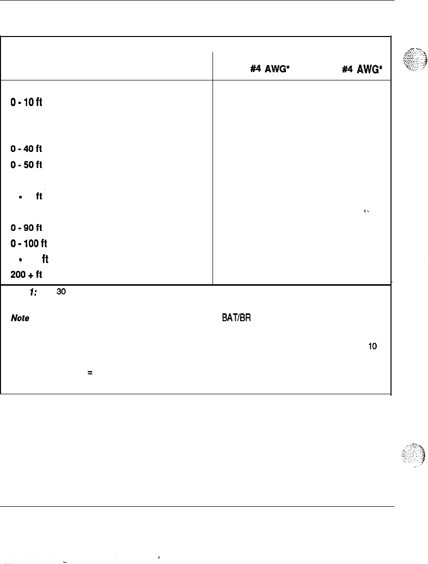
72 Power conductors
Table 22
Pedestal wire guage requirements with two 30 A feeds (five’wiresj
Wire AWG
Length Single Dual conduit Junction box with Junction box with
conduit single #4 AWG’ double
#I4
AWG*
8 6 4 4
O-loft
Yes Yes Yes Yes
0-20ft
Yes Yes Yes Yes
o-3oft
Yes Yes Yes Yes
0-4Oit
Yes Yes Yes Yes
0-50ft
Yes Yes Yes Yes
0-60ft
No
Yes
Yes
Yes
0
-
70
ft.
No
Yes Yes Yes
0-80ft
No
Yes Yes
Yes
‘-
0-90ft
No No
Yes Yes
o-looft
No No
Yes Yes
0
-
200
ft
No No No
Yes
200+ft
No No No No
Note 1: Two
30
A feeds are typically adequate for a full column of 4 modules (two 30 A feed pairs plus
Logic return).
Note 2: When using dual conduit, the wires must be run in BAT/BR pairs. One pair in one conduit and one
pair plus LRTN in the other conduit.
l
A single or double run of 4 AWG wire from the distribution point to
a
junction box near the pedestal.
10
AWG wire is run from the junction box into the pedestal PDU terminal board.
Legend:
Yes
=
Wire size is adequate for the distance.
No
= Wire size has too high a voltage drop and is inadequate for the distance.
Power engineering 553-3001-l 52
73.
List of terms
AC
ACEG
AWG
BAT
BR
bkr
BRTN
CE
CEC
ckt
CPC
CSA
DC
DisChg
EPE
FGND
Alternating Current
AC Equipment Ground
American Wire Gauge
Battery
Battery Return
breaker (abbreviation)
Battery Return
Common Equipment
Canadian Electrical Code
circuit (abbreviation)
Common Product Code
Canadian Standards Association
Direct Current
Discharge
Existing PE
Frame Ground
Power engineering 553-3001-l 52
74 List of terms
HZ
IG
I
inverter
LR
LRE
MPDU
mS
NEC
PBX
Pcord
PDU
PE
PEC
PFTU
Pwr
QBLlP
QBL15
QCA13
QRFl2
RPE
SPG
telco
Hertz (cycles per second)
-
Isolated Ground
DC to AC converter
Logic Return
Logic Return Equalizer
Module (UEM) Power Distribution Unit
millisecond
National Electrical Code (USA)
Private Branch Exchange
Power Cord (abbreviation)
Power Distribution Unit (in pedestal)
Peripheral Equipment (line card equipment)
Product Engineering Code
Power Fail Transfer Unit
Power (abbreviation)
75 Amp external power distribution unit
150 Amp external power distribution unit
50
-
200 Amp rectifier/distribution (cabinet]
25
Amp rectifier
Remotely located PE
Single Point Ground
telephone company (abbreviation)
Power engineering 553-3001-l 52
.
.

List of terms 75
UEM
UL
._\
-I.
::
-,
:z.;
I-
..;.,
ups
.i
L.ZeI
,T
.-.
._:<
VAC,Vac
VDC.Vdc
W
Universal EQuipment Module
Underwriters Laboratories
Uninterruptible Power System
Volts AC
Volts DC
Volts peak
Power engineering 553-3001-l 52
. ..’
‘...

SL-1
System options
21,51,61,71
Power engineering
Copyright
0
1990 Northern Telecom
All rights reserved.
information subject to change without notice.
Release 1.0
Standard
January, 1990
Printed in U.S.A.
::.:.“,,
3
:
;
.
.
:/
ic.:
-:
,~
;.i
:
.::.
.,-
:
_::
!._,
<:::-7.‘
:-:
::
?-i ,.
.
.
.
^
:,
.
.
:
.~
,.
SL-1
System options
21,51,61,71
Spares planning
Standard

SL-1
System options 21,5-l, 61,71
Spares planning
Publication number: 553-3001-153
Document release: 1 .O
Document status: Standard
Date: January
29,199O
. .
-
0
1990 Northern
Telecom
All rights resewed.
Spares planning 553-3001-l 53
.
.

ii
Revision history
January 29,199O
Standard, release 1.0
Spares planning 553-3001-153
.
.
iii
About this document
General information
The Spares planning guide provides all the information necessary for the
calculation and planning of spares (replaceable) items and provides failure
rates for the SL-1 hardware.
The success of a maintenance program depends largely on the availability of
an adequate stock of replaceable items. To ease maintenance and system
reliability, follow the procedures given here for calculating spares stocks.
Spares requirements can be calculated to service SL-1 systems from a single
depot (repair house) or a centralized depot serving subdepots. Read on for
more information.
-
This document has been updated to include new naming conventions. Since
the SL-1 is available in both AC and DC versions, the Product Engineering
Code (PEC) is given, in some cases, for both AC and DC power options.
The failure rates of some items may not appear in this release.
Note:
Running the SL-1 system at lower temperature levels will
increase the life expectancy of the components and improve overall
system reliability.
References
See the SL-1 planning
&
engineering guide
for
.I
:
^_
^
-
Muster index
(553-3001-000)
_..
. . .
.;
::;
::
:.:
.,‘!
-
System overview
(553-3001-100)
-
Installation planning
(553-3001-120)
Spares planning 553-3001-l 53
iv About this document
-
System engineering
(553-3001-151)
-
Power engineering
(553-3001-152)
-
Sparesplanning (553-3001-153)
-
Equipment identflcation and ordering
(553-3001-154)
See the list of line and trunk circuit descriptions in
the Master index
(553-3001-000) for specific references to lines and trunks.
See the SL-1 installation and maintenance guide
for
-
System installation procedures
(553-3001-210)
-
Circuit pack installation and testing
(553-3001-211)
-
Installation procedures for telephone
sets and attendant consoles
(553-2201-215)
-
Extended systems installation
(553-3001-250)
-
Disk drive upgrade procedures
(553-3001-251)
-
General maintenance information
(553-3001-500)
-
Fault clearing (553-3001-510)
-
Hardware replacement
(553-3001-520)
See the SL-1 XII software guide
for an overview of software architecture,
procedures for software installation and management, and a detailed
description of all Xl 1 features and services. This information is contained
in two documents:
-
Xl1
software management
(553-3001-300)
-
Xl1
features and services (553-3001-305)
See the SL-1
Xl1
input/output guide
(553-3001-400) for a description of all
administration programs, maintenance programs, and system messages.
Spares planning 553-3001-l 53

Contents
V
Spares planning
1
Definitions and assumptions
1
Calculating spares requirements 5
Tables: NFT values
7
Failure rates
Spares planning 553-3001-l 53
s.
:..
:

vi Contents
._
.i
. .
.-.
,“.
::.
‘:.
1.
1
Spares planning 553-3001-l 53

1
Spares planning
Definitions and assumptions
Failure
rate-Failure rate equals the estimated number of failures for that
item during one million (106) hours of operation. The only exception is to
measurements for cabling or other items with low failure rates. Rates are
also measured in Failures in Time (FIT) measurements. One FIT equals one
billion (109) hours of operation.
. .
Sparing interval-The
sparing interval is the period of time that stocks of
replaceable items should last without being replenished. This period is
assumed to be one year following the installation of the system.
Stock confidence
level-The stock confidence level is the allowed _-
probability of not being out of stock when the sparing interval of one year is
greater than 99.9 percent.
Pack ambient temperature-The
pack ambient temperature is the average
temperature of the air immediately surrounding the circuit pack (usually
higher than the ambient room temperature). Pack failure rates in this
document are based on a pack ambient temperature of
40’
C.
Spares planning 553-3001-153
..:
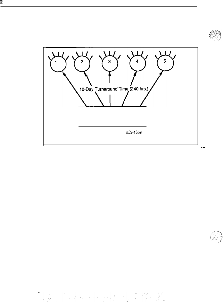
2
Definitions and assumptions
Turnaround time for rep&r-The
turnaround time for the return to stock
of a failed item is about 10 working days (240 hours) from a repair house.
(See Figure 1.)
Figure 1
Single depot or repair house service
Repair House
553-1559
Depots
I
--
Spares planning 553-3001-153
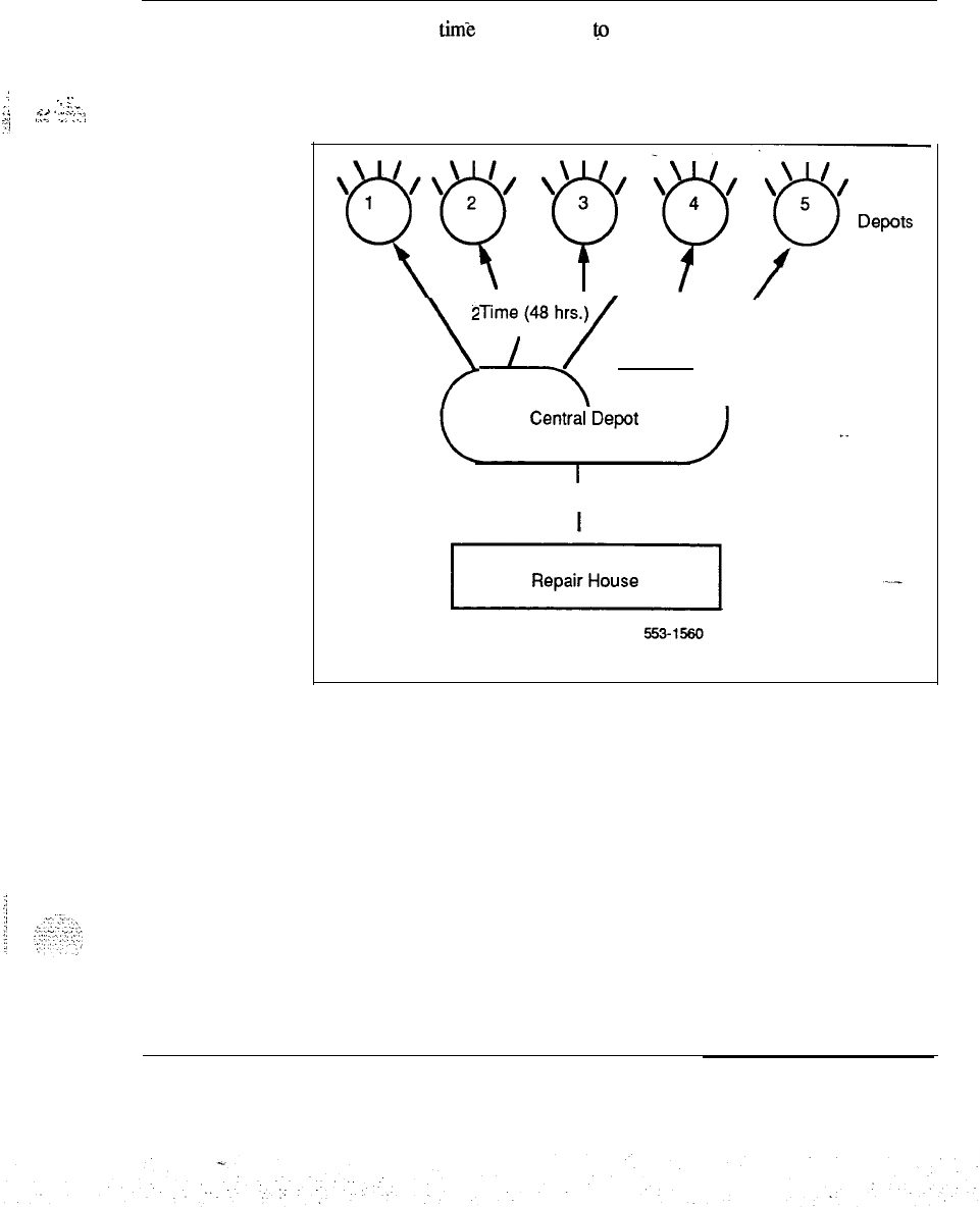
Definitions and assumptions 3
.:
. . L
.,
,.
.
.
1.: ...%-.
,“TS
.:I:.::
:1:
The turnaround timk for the return
&I
stock of a failed item is about two
days from a centralized depot, (See Figure 2.)
Figure 2
Centralized depot service
1 O-Day Turnaround Time (240 hrs.)1 O-Day Turnaround Time (240 hrs.)
Y-Day
;rnaro,und
Tirnry
Spares planning 553-3001-153
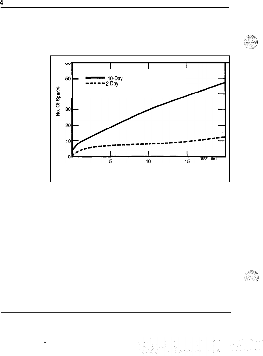
4
Definitions and assumptions
Actual turnaround periods Will vary in the field. As the number of systems
served increases, the percentage of replaceable items required for stock is
reduced. (See Figure
3.)
Figure 3
Effect of turnaround on spares stock
“”
I
II
50
-
50
-
-
lo-Day turnaround
-
lo-Day turnaround
-----2-Day
turnaround
-----2-Day
turnaround
EE
$
40-
$
40-
N
O
.
In Field (Thousands)
N
O
.
In Field (Thousands)
Population range-Population range
is the quantity of each type of SL-1
switch in the area served by the depot.
Spare stock size-The
quantity of spares for a given stock item depends on
the sparing interval, stock confidence level, failure rate, turnaround time for
repair, and population range.
Spares planning 553-3001-l 53

Definitions and assumptions 5
Calculating spares requirements
Replaceable items and their associated failure rates are listed in this
document. Quantities of spares required to stock a depot for the one-year
sparing interval can be calculated by following the procedures. Table 1
translates the NPT values to the number of spares required for that item.
The following values are used:
N-The number of a spares item in use.
F-The failure rate for a particular spares item.
T-The turnaround time for repairing a failed spares item in hours.
Procedure 1 explains how to calculate the quantities of spares required to
stock a depot for the one-year sparing interval:
-
:
_.!
:;
..,..
~
:..,;
Spares planning 553-3001-l 53
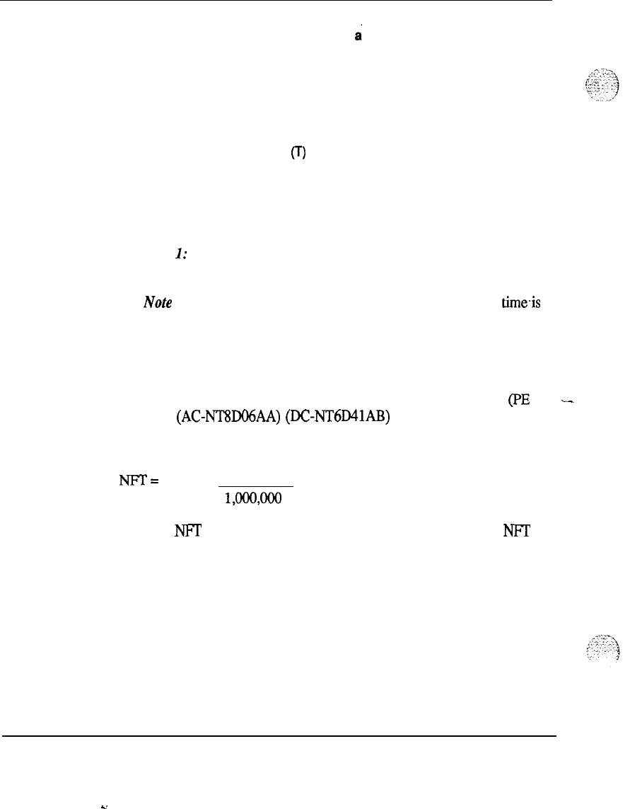
6 Definitions and assumptions
Procedure 1
Determining spares quantities to stock
a
depot for the one-year sparing
interval
1
Determine the number (N) of in-service specified circuit packs serviced
by the depot.
2Determine the pack failure rate (F) for the specified circuit pack in the
Spares planning guide. (See Note 1 below.)
3Determine turnaround time (T) in hours. (See Note 2 below.)
4
Calculate the NFT value by multiplying N x F x T.
5Determine the number of spares required by using the NFT values in
Table 4.
Note
I:
Pack failure rates are expressed in terms of the number of
failures per million hours.
Note
2:
For a single depot or repair house service, turnaround
timeis
typically 10 working days or 240 hours. For a centralized depot
service, it is typically two days or 48 hours.
For example:
A single depot services 10,000 Peripheral Equipment Power Supply (PE _-
Pwr Sup) (AC-NT8DO6AA)
(DCNT6D41AB)
packs. From the failure
rates listed in Table 2, the failure rate for this pack is 1.84 failures per one
million hours. If the turnaround time for a single depot is 48 hours, then:
NFT=
10,000 x 1.84
x 48 = 0.8832
WWOO
From the
NIT
values in Table 1, the number of spares required for NFT
value 0.8832 = 6. See Table 1.
Spares planning 553-3001-l 53
s.
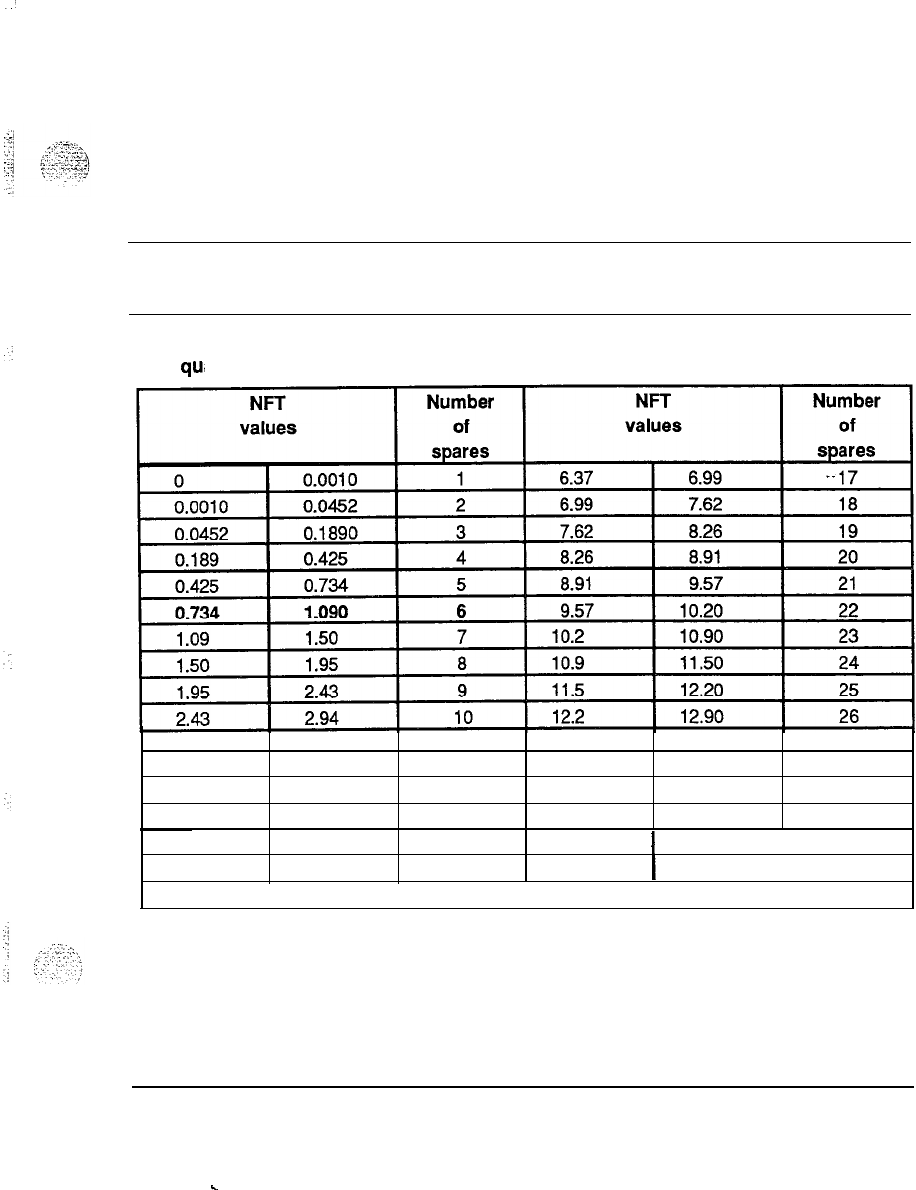
7
Tables: NFT values
Table 1
Stock
qu,
antity of spares
2.94
3.46
11
12.9 13.60
27
3.46 4.01 12 13.6 14.30
28
4.01 4.58 13 14.3 15.00
29
4.58 5.16 14 15.0 15.80
30
5.16 5.76
5.76 6.37 15 15.8
16 16.5
-continued-
1
16.50
i
31
1
17.20
32
Spares planning 553-3001-153
.
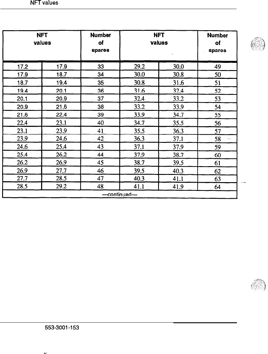
8 Tables:
NFTvalues
Table 1 continued
Stock quantity of spares
Spares planning
553-3001-153
-.
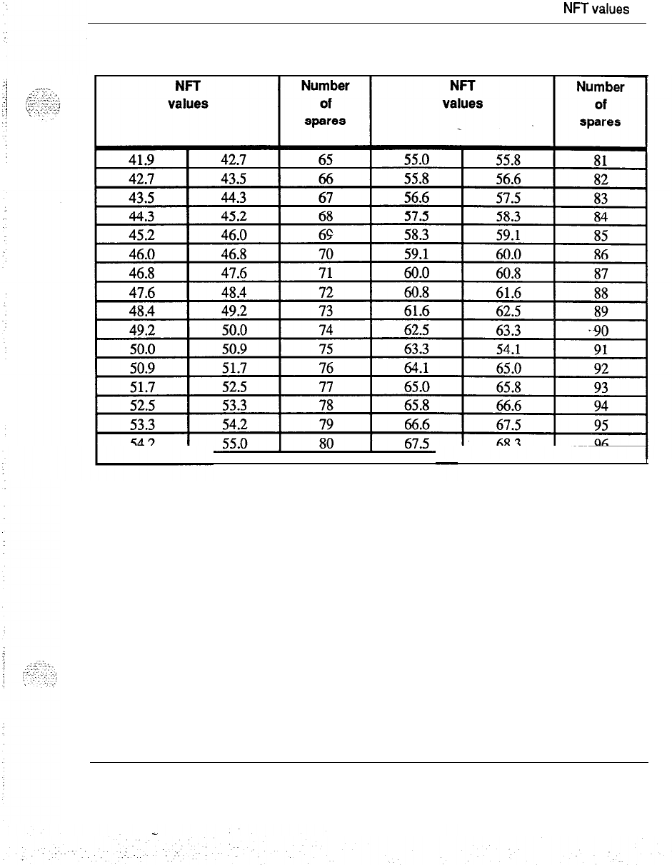
Tables:
NFTvalues
9
Table 1 continued
Stock quantity of spares
-continued-
Spares planning 553-3001-l 53
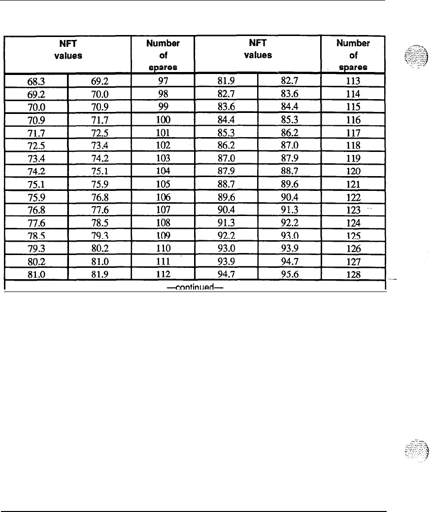
10 Tables: NFT values
Table 1 continued
Stock quantity of spares
Spares planning 553-3001-l 53
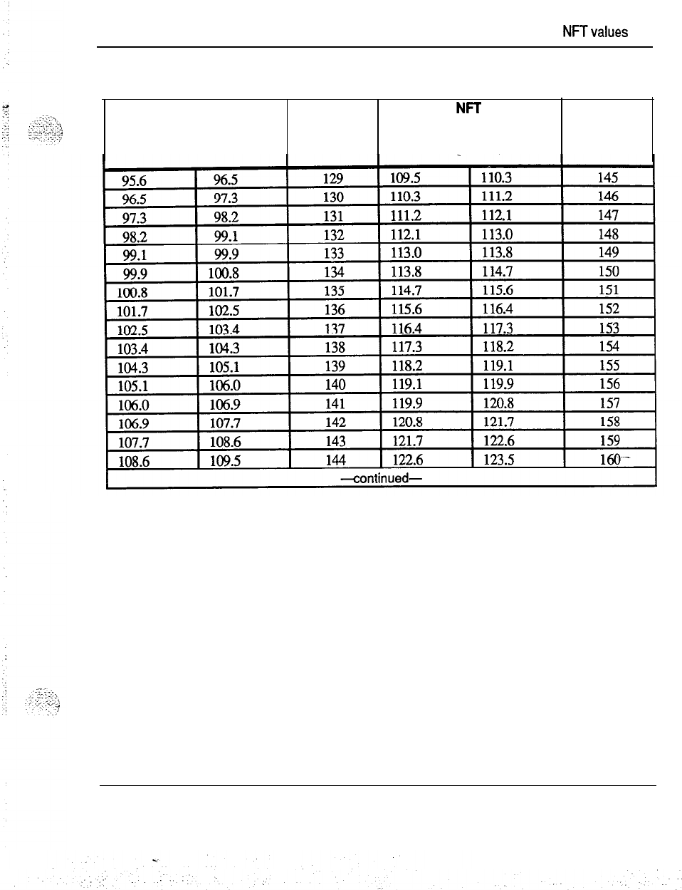
Tables:
NFTvalues
11
Table 1 continued
Stock quantity of spares
NFT
values
Number
of
spares
NFT
values Number
of
spares
Spares planning 553-3001-153
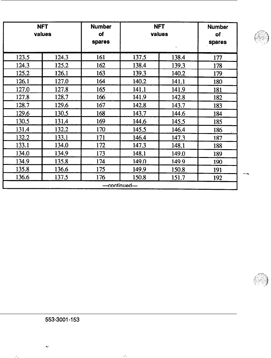
12 Tables: NFT values
Table 1 continued
Stock quantity of spares
Spares planning
553-3001-153
.d
:
.
.
:.
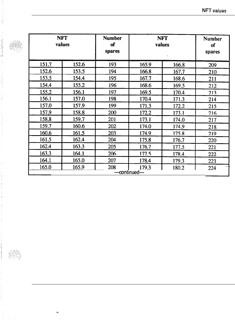
Tables:
NFTvalues
13
Table 1 continued
Stock quantity of spares
-amtinued-
Spares planning 553-3001-l 53
k.
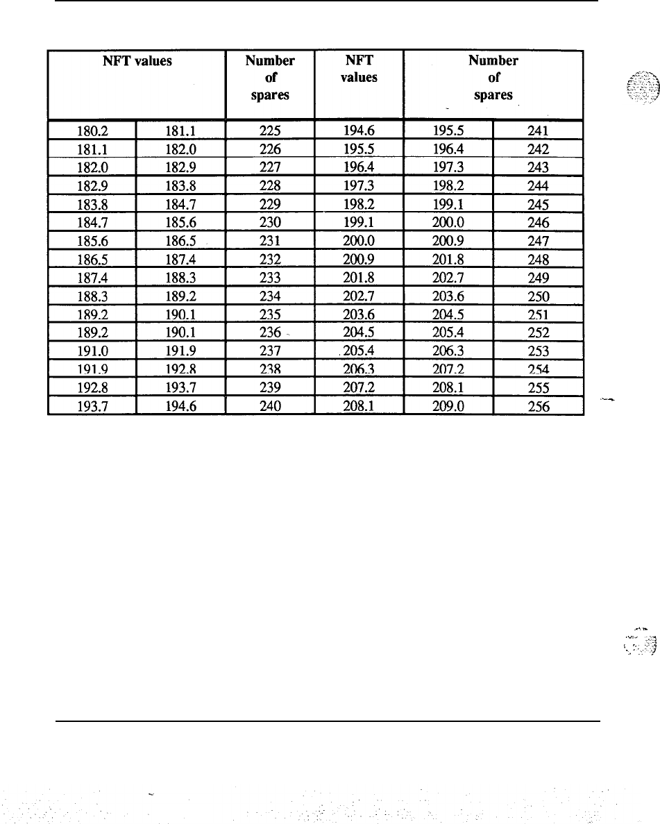
14 Tables: NFT values
Table 1 continued
Stock quantity of spares
_.-
._,..
. .
s
:-.
.‘-’
-..
.”
.j
Spares planning 553-3001-l 53

15
Failure rates
This section lists replaceable items used in SL-1s and provides their
associated failure rates. Some failure rates are not available (N/A) at this
time but will be offered in a supplement to this document. The replaceable
items are grouped according to equipment types as follows:
-
universal equipment modules
-
cooling equipment
-
circuit packs
-
station equipment
-
power equipment
-
mass storage equipment
Note:
The failure rates are based on a circuit pack ambient
temperature of
40’
C. This temperature is usually higher than the
surrounding room temperature.
3
,.
.;:.
;
;,
-::.
,-
.,.:;
.,.::
..a
. .
.’
Spares planning
553-3001-l 53
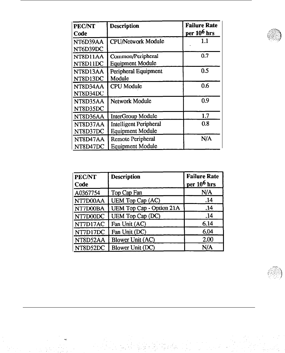
16 Failure rates
Table 2
Failure rates of modules
1
Table 3
Failure rates of cooling equipment
Spares planning 553-3001-153
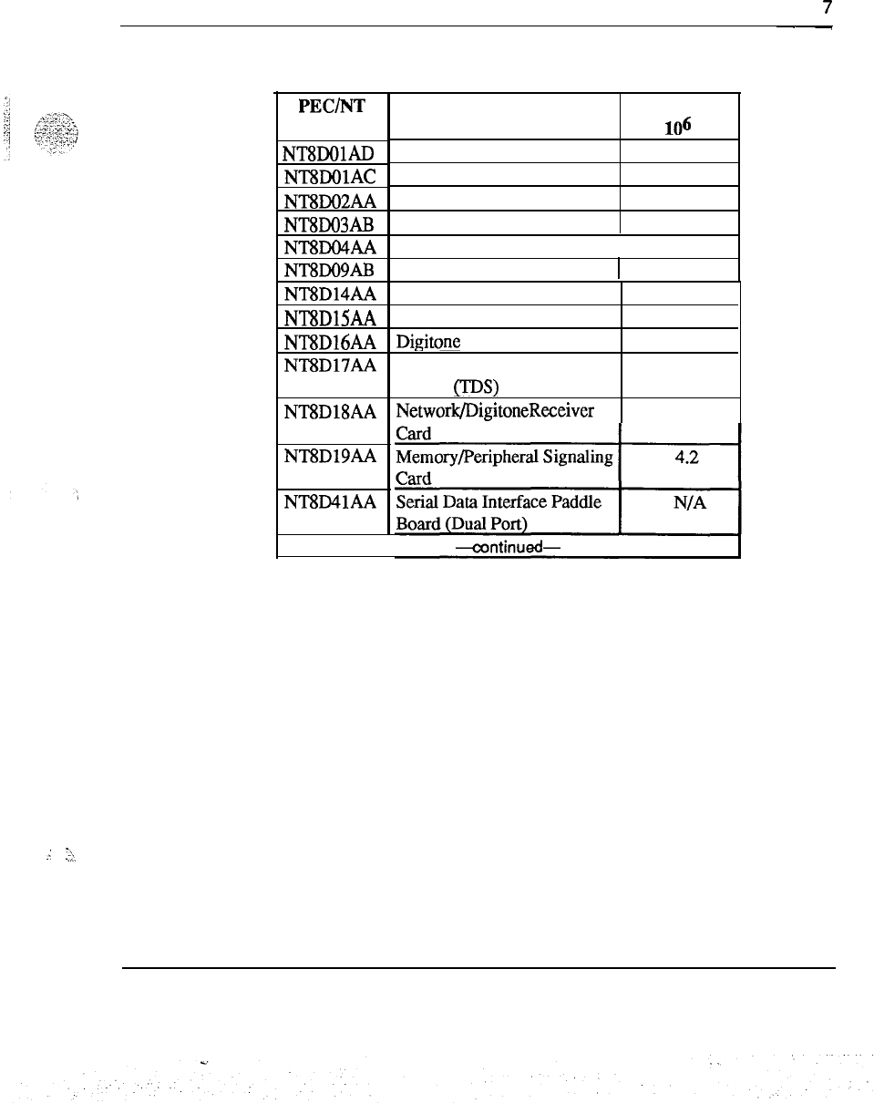
Failure rates 1
i’
--
Table 4
Failure rates of circuit packs
PEC/NT
Code
NT8DOlAD
NTSDOlAC
NT8DO2AA
NT8DO3AB
NT8DO4AA
NT8DO9AB
NT8D14AA
NT8DlSAA
NT8D16AA
NT8D17AA
NT8D18AA
NT8D19AA
NT8D41AA
Superloop Network Card
Description
Controller-2
Message Waiting Line Card
Controller-4
Digital Line Card
Analog Line Card
I
Failure Rate
per
106 hrs
5.1
1
6.5
5.8
7.0
1.8
5.1
Universal Trunk Card
E&M Trunk Card
Digitone Receiver Card
Conference/Tone and Digit
Switch
OS)
Card
Network/DigitoneReceiver
3.4
3.7
2.7
5.1
7.3 .
!
.;
.?,
Spares planning 553-3001-l 53
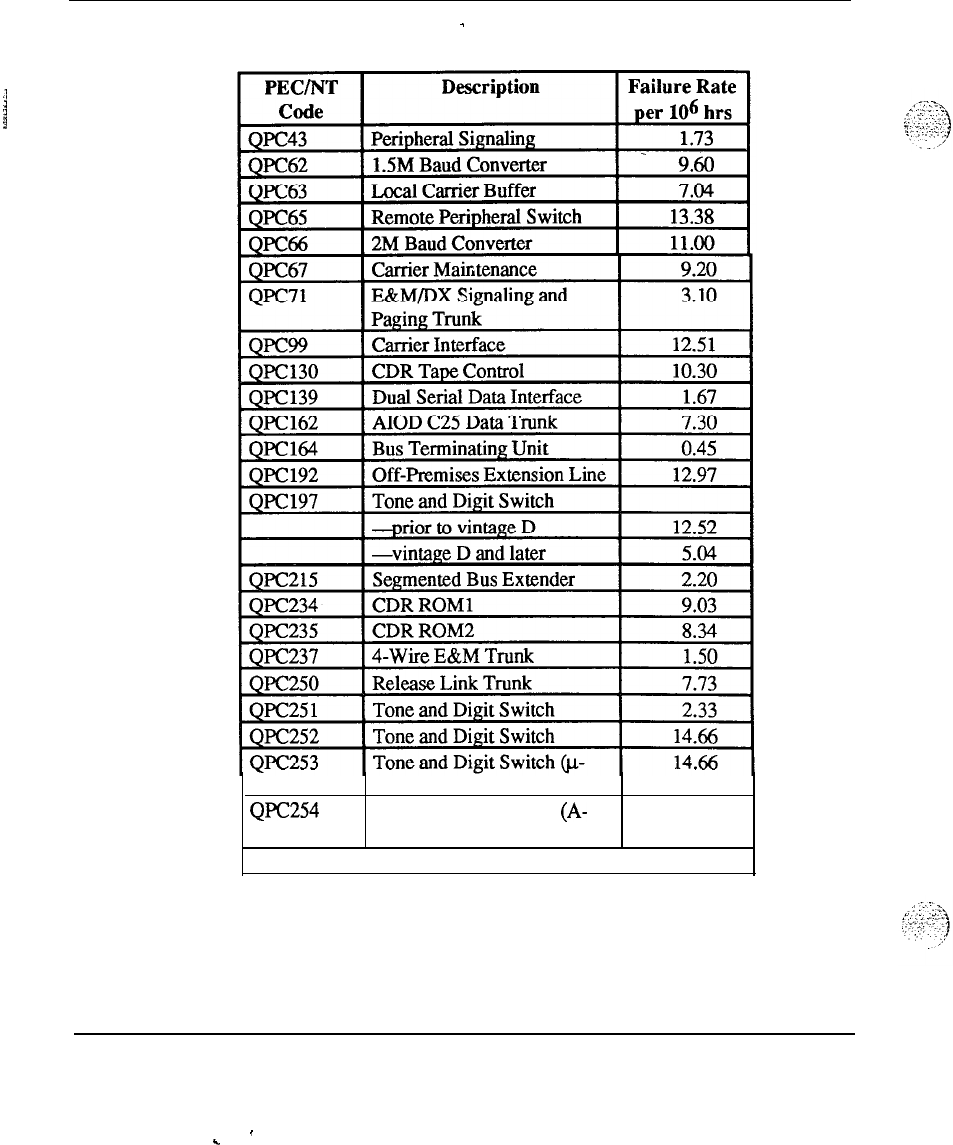
18 Failure rates
Table 4 continued
-
Failure rates of circuit packs
Law)
QPC254
Tone and Digit Switch
(A- 14.66
Law)
--continued-
,
Spares planning 553-3001-l 53
’
.
.
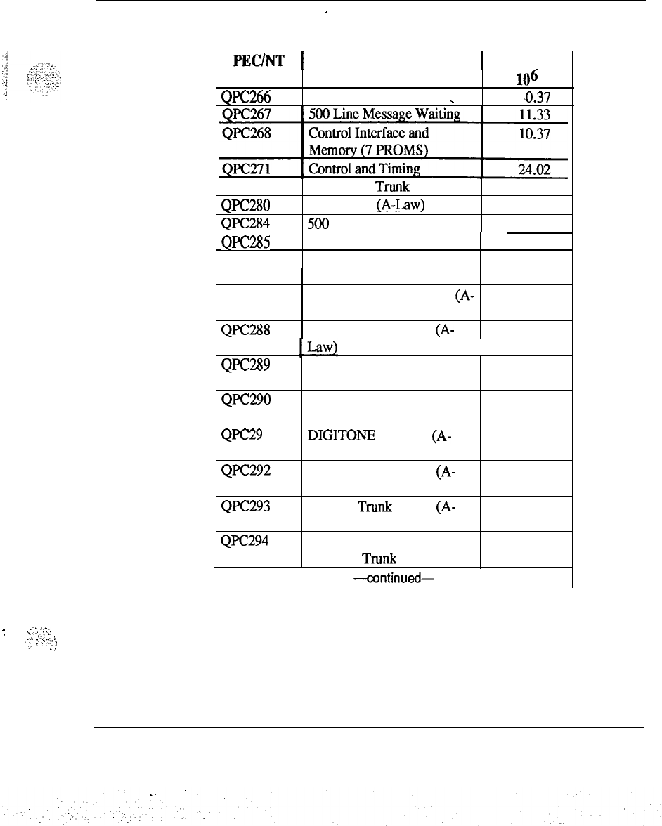
Failure rates 19
.;
.‘.:.
-:‘-.
(
.-.
.I,
:
;
=,;
:
.
...;
./
Table 4 continued
-
Failure rates of circuit packs
PECINT
1
Description
1
Failure Rate
Code
QPc266
ACD Interface
_
per
106 hrs
.0.37
QPC272 CO and FX Trunk 10.90
QI’C280 Conference (A-Law) 13.95
QPC284 500 Line Circuit (A-Law) 8.53
QPC285
QPC286
SL- 1 Line Circuit (A-Law)
500 Line Message Waiting
(A-Law)
E&M, DX, Paging Trunk (A-
Law)
Loop Signaling Trunk (A-
5.45
8.61
QPC287
QPC288
6.97
7.09
QF’C289
QPC290
QF’C29
1
QPC292
QPC293
QF’C294
Recorded Telephone
Dictation Trunk (A-Law)
Recorded Announcement
Trunk (A-Law)
DIGITONE Receiver (A-
Law)
OPX 500 Line Circuit (A-
Law)
CO, FX Trunk Circuit (A-
Law)
Recorded Telephone
Dictation Trunk (A-Law)
-continued-
8.19
5.61
6.68
12.75
6.44
7.22
Spares planning 553-3001-153
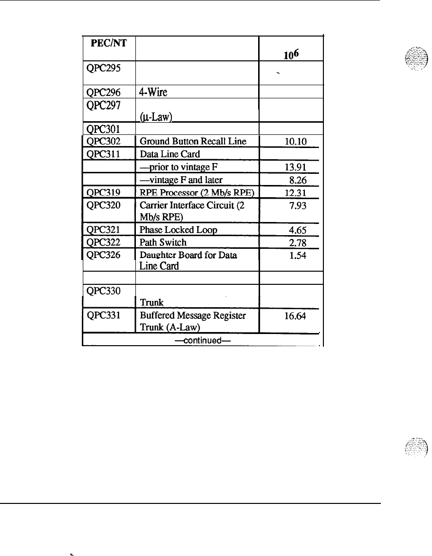
20 Failure rates
Table 4 continued
-
Failure rates of circuit packs
PEC/NT
Description Failure Rate
Code per
lo6
hrs
QlT295
CO, FX, MR DET Trunk
_
10.46
Ql’C296
QPC297
Circuit
(A-Law)
4-Wire E&M Trunk (A-Law)
Attendant Console Monitor
8.38
7.85
QPC301
@Law)
CDR ROM 10.05
QPC327
QPC330
LineCard
MFC Sender/Receiver
Buffered Message Register
20.07
9.78
/“‘“’
Spares planning 553-3001-153
.
.
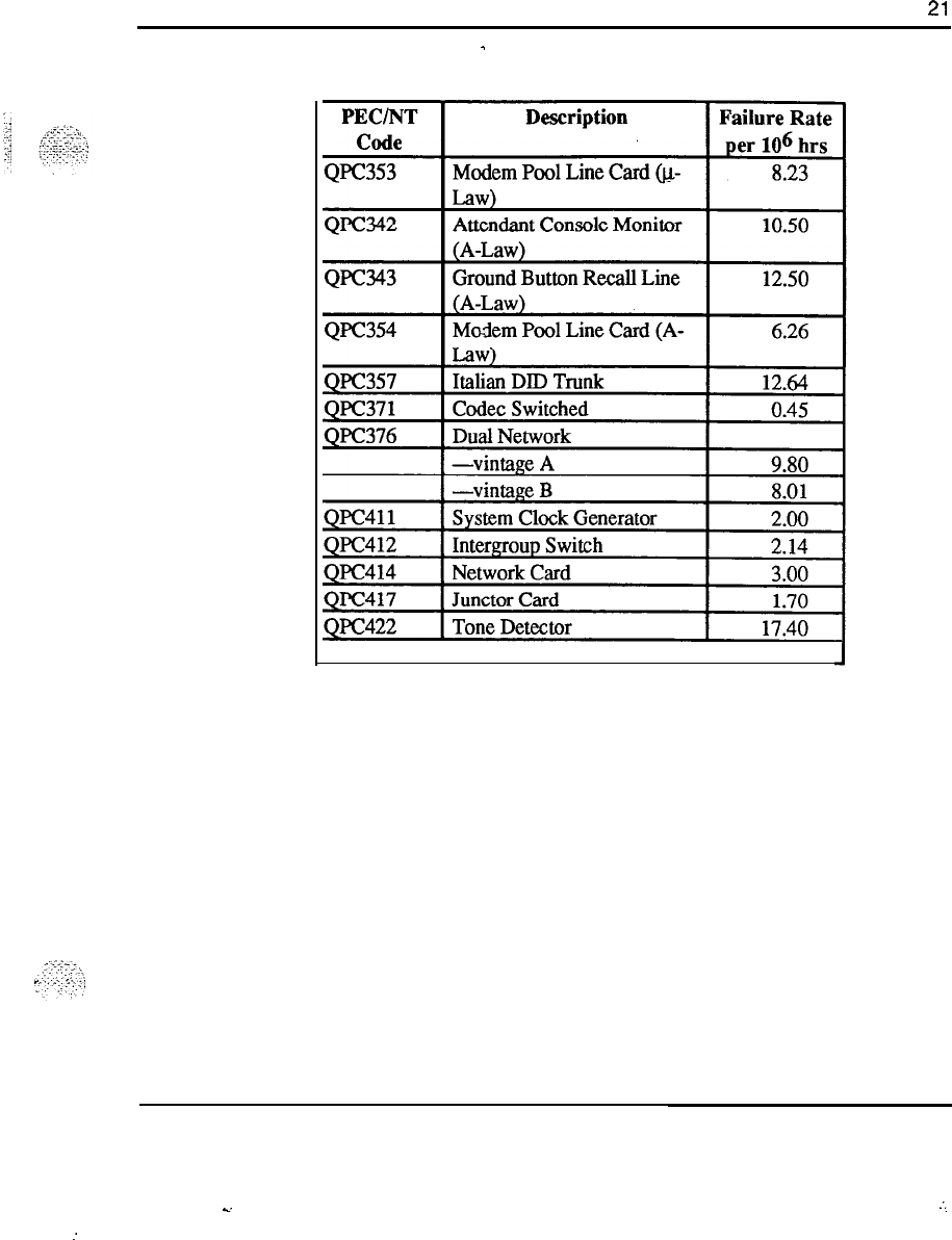
Failure rates
21
Table 4 continued
-
Failure rates of circuit packs
-continued-
Spares planning 553-3001-153
-.
:.
:
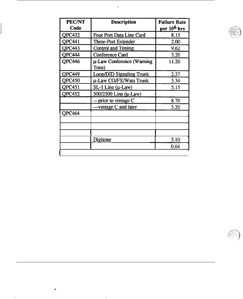
22 Failure rates
Table 4 continued
-
Failure rates of circuit packs
QPC464
Peripheral Buffer 9.00
QPC47 1 Clock Controller 2.44
QPC472 Digital Trunk Interface 6.00
QPC473
1
DTI Carrier Interface
!
6.60
QPC475
QPC477
1
Digitone Receiver
[
Bus Terminating Unit
I
-continued-
I
Spares planning 553-3001-153
c
:
:
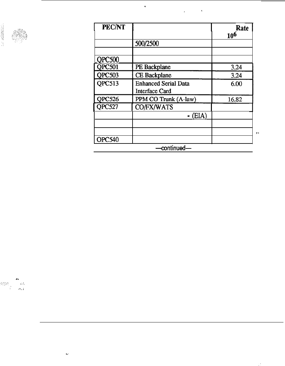
Failure rates 23
Table 4 continued
-
Failure rates of circuit packs
1
PEC/NT
1
Description
1 Failure
Rate1
Code
QPC494
QPC496
QPC500
500/2500 Message Waiting
Extender
PE Backplane
per
lo6
hrs
8.00
0.69
3.24
1
QFC527
QPC528
QPC532
QPC536
OF040
1
CO/FX/WATS trunk (A-law)
1
12.37
1
CO/IX/WATS trunk
-
(EIA) 14.23
Grd Button Line Card 13.93
Digital Trunk Interface
12.36
.-
Tone Detector
6.49
I
-continued-
1
-.
..:,:.:
,:,
,’ .-,
,
Spares planning 553-3001-l 53
c.
:
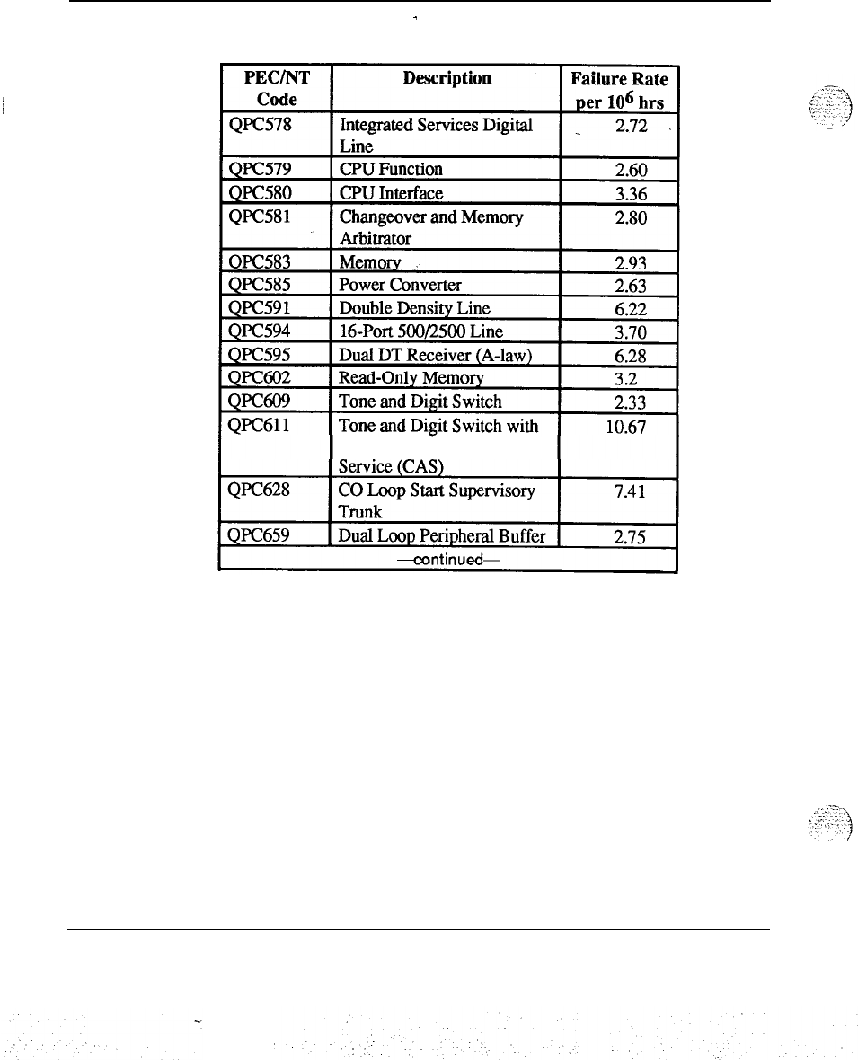
24 Failure rates
Table 4 continued
-
Failure rates of circuit packs
Centralized Attendant
Spares planning 553-3001-153
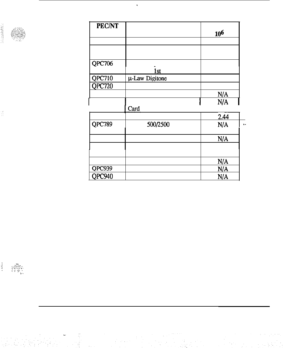
Failure rates 25
Table 4 continued
-
Failure rates of circuit packs
PEC/NT
Description Failure Rate
Code
per
lo6
hrs
Ql’C673 512K RAM Memory Card 5.04
QPC674 256K Memory
with
Error 5.80
Correction
QPC706 Half PE Expansion Power 1.14
QPC710
QPC720
QPC723
Converter,
ist
tier
p-Law Digitone Receiver
Primary Rate Interface Card
RS-232 Interface Line Card
5.20
6.00
N/A
1
QPC757
1
D-Channel Handler Interface
1
N/A
1
QPC775 Clock Controller Card 2.44
Ql’C789 16-Port 500/2500 Line
N/A
I-
QPC814
QPC841
(Message Waiting)
Memory
Four-Port Serial Data
N/A
.
2.2
QPC918
QPC939
QPC940
Interface Card
High-Speed Data Card
Read-Only Memory
Read-Only Memory
N/A
N/A
N/A
.j
..-..,
..
-...:.:.:.:.
:
:
i
;.
I::
‘.
i
.,
i
I..
Spares planning 553-3001-l 53
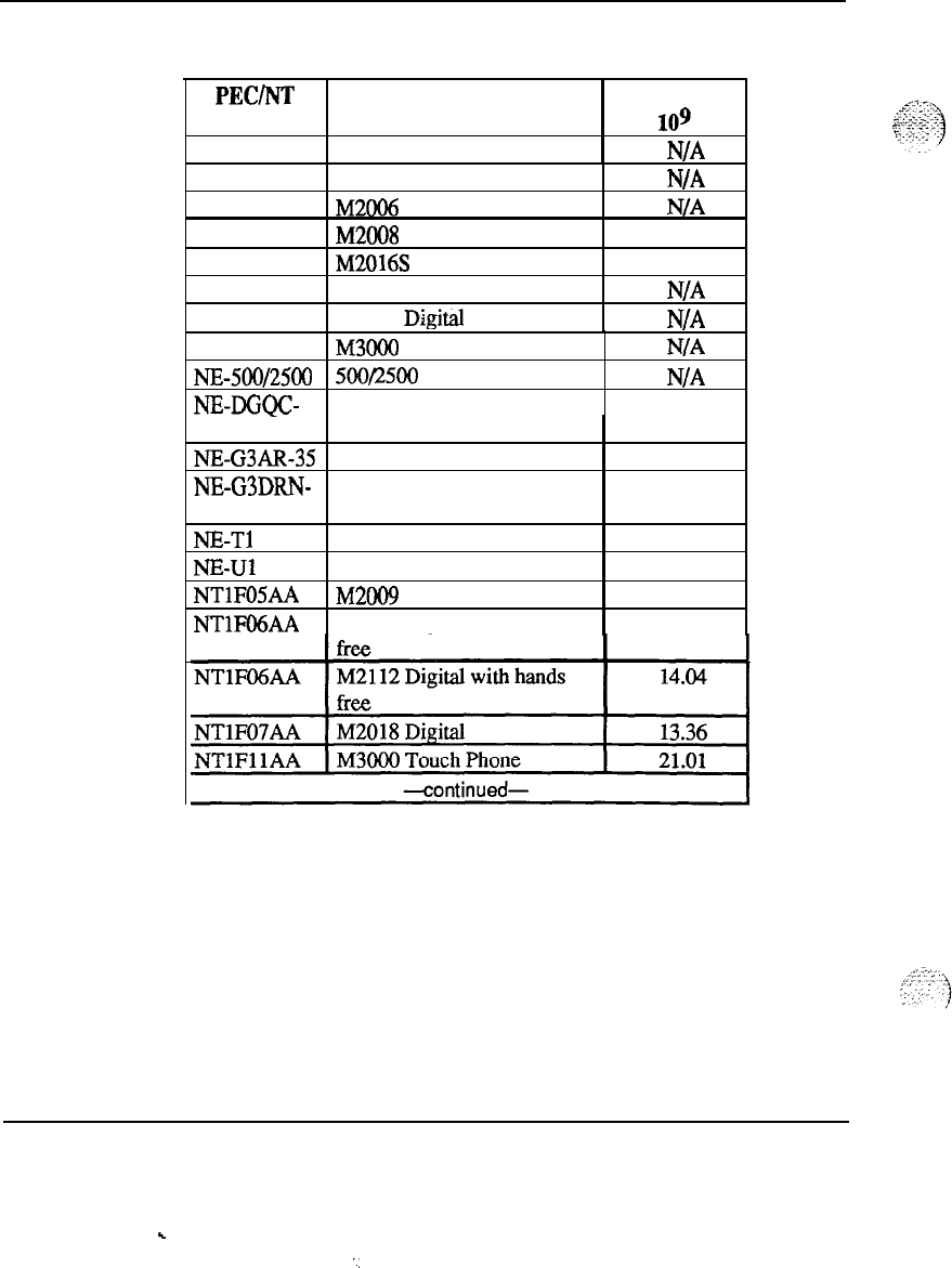
26 Failure rates
Table 5
Failure rates of station equipment
PEC/NT
Description Failure Rate
Code per
lo9
hrs
Ml250 Console
N/A
M2250 TCM Console
N/A
M2006 Digital Telephone
N/A
M2008 Digital Telephone 3.10
M2016S Digital Telephone 3.90
M2216 Digital Telephone
M2616
Digital
Telephone
N/A
N/A
M3000 Touchphone
N/A
NE-500/2500 500/2500 Telephone Set
N/A
NE-DGQC- Line Cord 3.50
35
NE-G3AR-35 Handset
NE-G3DRN-
Console Handset
3
NE-T1 Transmitter
NE-u1
Receiver
NTIFOSAA M200!9 Digital Tel Set
NTlFO6AA M2012 Digital without hands
0.50
0.50
0.50
0.50
12.22
12.44
Spares planning 553-3001-153
.
.
..
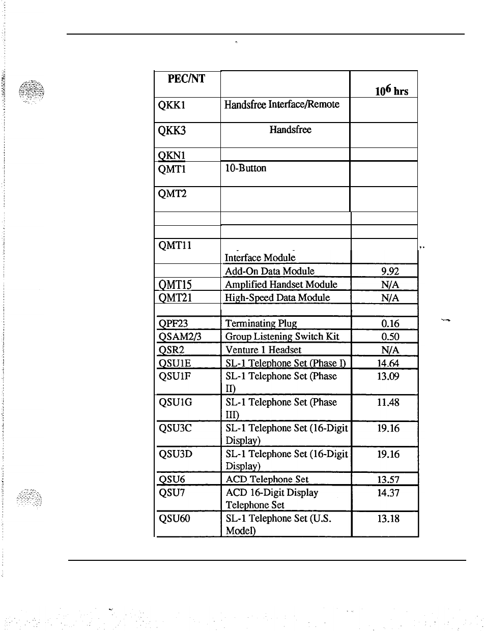
Failure rates 27
Table 5 continued
-
Failure rates of station equipment
PEC/NT
Code
Q=l
Q
,::
QM-I-2
QMT3
QMT4
QMTll
QMT12
QMTl5
QMT21
Description Failure Rate
per
lo6
hrs
Handsfiee
Interface/Remote 0.33
Powering Kit
Automatic Handsfree 0.82
Interface Kit
Headset Kit 0.25
lo-Button
Key Lamp 2.89
Expansion Module
20-Button Key Lamp 4.73
Expansion Module
Lamp Field Array Module 13.99
Handset Module 0.50
Asynchronous/Synchronous
6.34
.-
..-
Spares planning 553-3001-153
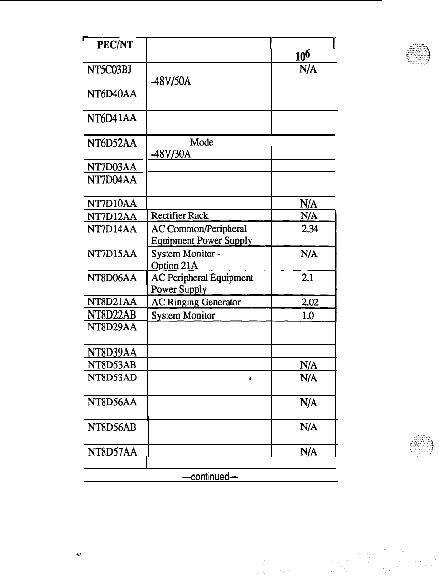
28 Failure rates
Table 6
Failure rates of power equipment
PEC/NT-
1
Description
1
Failure Rate
1
Code per 106 hrs
NTSC03BJ Switched Mode Rectifier
.
N/A
-48V/50A
NT6D40AA DC Peripheral Equipment
1.6
Power Supply
NT6D4 1AA DC Common Equipment 0.6
I
Power Supply
I
NT6D52AA
1
Switched Mode Rectifier
1.2
NTi’DO3AA
NT7DO4AA
43Vf30A
DC Ringing Generator
DC Common/Peripheral
1.81
3.14
Equipment Power Supply
NT7DlOAA DC Power Distribution Unit NIA
NT7D12AA
NT7D14AA
NT7DlSAA
NT8D21AA
NT8D22AB
NT8D29AA AC Common Equipment 1.27
Power Supply
NT8D39AA Power Failure Transfer Unit
5.7
NT8D53AB AC Power Distribution Unit
N/A
.
NT8D53AD Power Distribution Unit
-
N/A
Option 21 A
NT8D56AA
~
Module Power Distribution
N/A
Unit
NT8D56AB Module Power Distribution
N/A
Unit
NT8D57AA Module Power Distribution
N/A
I
Unit
I
+ontinued-
I
Spares planning 553-3001-153
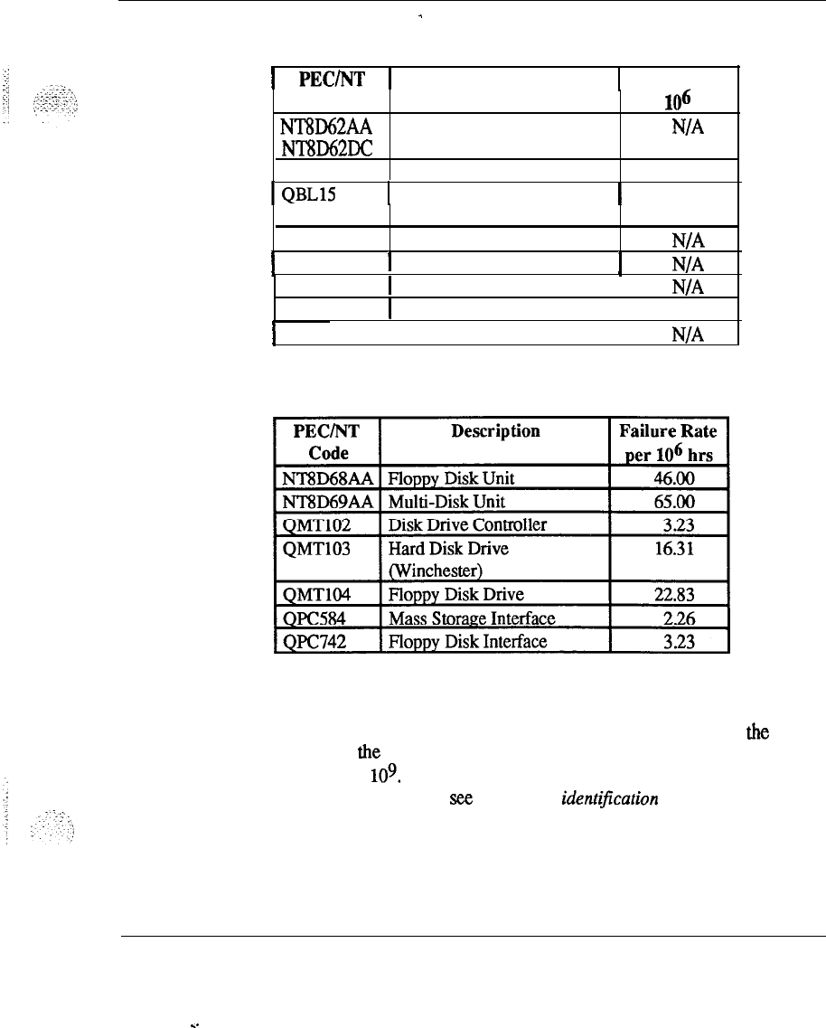
Failure rates 29
Table 6 continued
-
Failure rates of power equipment
1
PEC/NT
1
Description
1
Failure Rate
Code per
lo6
hrs
NT8D62AA Temperature Sensor Panel
N/A
NT8D62DC
QBL12
Battery Distribution Box 1.10
1
QBLl5
I
Power/Battery Distribution
I
2.81
QCA13
Box
DC Power Plant
1
QCA321
I
Junction Box
!
N/A
QPC188
QRF12
1
Battery Monitor
I
48V Rectifier
I
N/A
1.20
1
QRF12 I-52V Rectifier
I
N/A
Table 7
Failure rates of mass storage equipment
Note:
There are many replacement cables (not fisted here) in lengths
appropriate for various configurations available from Northern
Telecom. The approximated failure rates for most cables are the same
(0.50); the measurement is based on failures in time per billion hours
(FIT) or 109. For a detailed listing of the cables available from
Northern Telecom,
see Equipment identijication and ordering
(553-3001-154).
Spares planning 553-3001-153
.
.

SL-1
System options 21,51,61,71
Spares planning
Copyright
0
1990 Northern Telecom
All rights resewed.
Information subject to change without notice.
Release
1
.O
Standard
January 29, 1990
Printed in U.S.A.
nit
northarn
talocom
,..,
1:::::
::
:
-,:
:::
.:
‘;
SL-1
System options
21,51,61,?1
Equipment identification and
ordering information
Standard
C.

--
.
.
SL-1
System options
21,51,61,71
Equipment identification and ordering information
Publication number: 553-3001-154
Document release: 1 .O
Document status: Standard
Date: January
29,199O
. . .
.._”
,.
::-,
:
:-;
,.
_.;.:
.,.)
‘.
0
1990 Northern Telecom
All right reserved
Equipment identification and ordering information 553-3001-154
ii
Revision history
January 29,199O
Standard, release 1.0
Equipment identification and ordering information 553-3001-154
.
.
.
.
.
III
About this document
This document identifies equipment of the Meridian
1
System options 21,
5
1,61,71
that can be ordered individually. The items are described in
terms of purpose, quantity required, and system hardware (system option),
as appropriate.
References
See the SL-1 planning
&
engineering guide
for
-
Master index
(553-3001-000)
-
System overview
(553-3001-100)
-
Installation planning
(553-3001-120)
-
System engineering
(553-3001-151)
-
Power engineering
(553-3001-152)
-
Sparesplanning (553-3001-153)
See the list of line and trunk circuit descriptions in
the Master index
(553-3001-000) for specific references to lines and trunks.
See
the
SL-1 installation and maintenance guide
for
-
System installation procedures
(553-3001-210)
-
Circuit pack installation and testing
(553-3001-211)
-
Installation procedures for telephone
sets and attendant consoles
(553-3001-215)
-
Extended systems installation
(553-3001-250)
-
Disk drive upgrade procedures
(553-3001-251)
_-
Equipment identification and ordering information 553-3001-154
.
.
iv About this document
-
General maintenance information
(553-3001~500)
-
Fault clearing (553-3001-510)
-
Hardware replacement
(553-3001-520)
See the SL-1
XII
software guide
for an overviewbf software kchitecture,
procedures for software installation and management, and a detailed
description of all Xl 1 features and services. This information is contained
in two documents:
-
Xl1
software management
(553-3001-300)
-
Xl1
features and services (553-3001-305)
See the SL-I
Xl1
input/output guide
(553-3001-400) for a description of all
administration programs, maintenance programs, and system messages.
Equipment identification and ordering information 553-3001-154
c+
.
.
:..
V
Contents
General
1
Equipment packages
1
Conversion and expansion packages
1
Equipment availability
2
Special features
2
Product coding
.
2
Universal Equipment Modules and packaging
NT6D39AA, NT6D39DC CPU/Network Module
NT6D44AA, NT6D44DC Meridian Mail Module
NT8Dll
AC,
NT8Dll
DC
CUPE
Module
NT8D13AA, NT8D13DC Peripheral Equipment Module
--
NT8D34AA, NT8D34DC CPU Module
NT8D35AA, NT8D35DC Network Module
NT8D36AA Inter Group Module
NT8D37AA, NT8D37DC Intelligent PE Module
NT8D47AA, NT8D47DC Remote PE Module
NT8D49 Spacer Kit
NT8D55AA Universal Equipment Module cover
Universal Equipment Module side panel
Card cage assemblies
Top Cap
Pedestal
5
5
6
7
8
8
9
10
10
11
12
12
12
12
13
13
-,
:...
._
Power and cooling equipment 15
:.:
. . .
.,.
._
-L’
.:-.
;.
A0367754 Top Cap Fan
15
NT5C03BJ Switched Mode Rectifier -48V/50A
15
NT6D40AA Peripheral Equipment Power Supply DC
15
NT6D41 AA Common Equipment Power Supply DC
16
Equipment identification and ordering information 553-3001-154
vi Contents
NT6D52AA Switched Mode Rectifier -48V/30A
NT6D53AA Junction Box
NT6D5303 Logic Return Equalizer
NT7D0003 Fan and Sensor Panel
NT7D03AA Ringing Generator DC
NT7D04AA
CUPE
Power Supply DC
-
NT7DiOAA Power Distribution Unit DC
NT7D12AA Rectifier Rack
NT7D14AA CE/PE Power Supply AC
NT7D15AA System Monitor
-
System option 21 A
NT7D17AC Fan Unit AC
NT7D17DC Fan Unit DC
NT7D1201 Rectifier Baffle/Mounting Kit
NT8DOGAA Peripheral Equipment Power Supply AC
NT8D21 AA Ringing Generator AC
NT8D22AB System Monitor
NT8D29AA Common Equipment Power Supply AC
NT8D39AA Power Failure Transfer Unit
NT8D52AA Blower Unit
NT8D52DC Blower Unit
NT8D53AB Power Distribution Unit AC
NT8D53AD Power Distribution Unit
-
System option 21A
NT8D56AA Module Power Distribution Unit
NT8D56AB Module Power Distribution Unit
NT8D57AA Module Power Distribution Unit
NT8D62AA, NT8D62DC Temperature Sensor Panel
QBL12 Battery Distribution Box
QBL15 Power/Battery Distribution Box
QCA13 DC Power Plant
QPC188 Battery Monitor
QRF12 -52 V Rectifier
16
17
17
18
18
19
19
19
20
20
20
20
21
21
..22
22
23
23
23
24
24 --
24
24
25
25
26
26
26
27
Common Equipment cards
NT8D04AA Superloop Network
NT8D17AA Conference/Tone and Digit Switch (TDS)
NT8D18AA NetwotWDigitone Receiver
NT8DlSAA
Memory/Peripheral Signaling
NT8D41AA Serial Data Interface paddle board (Dual Port)
NT8D68AA Floppy Disk Unit
NT8D69AA Multi Disk Unit
Equipment identification and ordering information 553-3001-154
C.
.: :
:
Contents vii
QMM42 Security Data Cartridge
QPC43 Peripheral Signaling
,.;
QPC215 Segmented Bus Extender
. _ . . . .
:‘:
.--
.^
f:j
i
‘y’.,.$,:,
z.;
QPC412 Intergroup Switch
/“.._
-_
./
:,
.:
>‘,S
y::,,
QPC414 Network
QPC417 Junctor Board
QPC441 Three-Port Extender
QPC471 Clock Controller
QPC477 Bus Terminating Unit
QPC513 Enhanced Serial Data Interface
QPC579 CPU Function
QPC580 CPU Interface
QPC581 Changeover and Memory Arbitrator
QPC583 Memory
.;
QPC584 Mass Storage Interface
QPC687 CPU with SDVRTC
QPC720 Primary Rate Interface
QPC742 Floppy Disk Interface
QPC757 D-Channel Handler Interface
QPC841 Four-Port Serial Data Interface
QPC939 Read-Only Memory
QPC940 Read-Only Memory
32
32
32
32
33
33
33
33
34
34
35
35
35
35
36
36
36
37
37
37
38
38
;;...-
:.
_._.
._,
_
--.
,
;
.
...-....,
I.,
:
.:
1
..,’
Peripheral Equipment cards
-39
NT8DOl AD Controller-2 39
NT8DOl AC Controller-4 39
NT8D02AA Digital Line card
40
NT8D03AB Analog Line card
40
NT8DOSAB Analog Message Waiting Line card
40
NT8D14AA Universal Trunk
41
NT8DlSAA
E&M Trunk
42
NT8D16AA Digitone Receiver
43
QPC62 1.5 Baud Converter
43
QPC63 Local Carrier Buffer
43
QPC65 Remote Peripheral Switch
44
QPC66 2M Baud Converter
44
QPC67 Carrier Maintenance
45
QPC71 E&M/DX Signaling and Paging Trunk
45
QPC99 Carrier Interface
46
QPC192 Off-Premises Extension Line
46
Equipment identification and ordering information
553-3001-l 54
viii Contents
QPC237 4-wire E&M/DX signaling trunk 46
QPC250 Release Link Trunk 47
QPC297 Attendant Console Monitor 47
QPC422 Tone Detector
47
;:‘:5~:
QPC430 Asynchronous Interface Line 48
_.
. _
‘l.z. 3
-<<.x-s.;
1
.J
QPC432 4-Port Data Line 48
QPC449 Loop Signaling Trunk 48
QPC450 CO/FWWATS Trunk 49
QPC578 Integrated Services Digital Line 49
QPC594
16-Port
500/2500
Line
49
QPC659 Dual Loop Peripheral Buffer 49
QPC723 RS-232 4-Port interface Line 50
QPC789 16-Port 500/2500 Line (Message Waiting) 50
QPC918 High-Speed Data Card 50
Station equipment
51
Meridian Modular Telephones
. . 51
M2000 series digital telephones 60
M3000Touchphone
61
NE-500/2500 telephone set
61
Ml 250 and 2250 attendant consoles
61
Attendant administration overlay template 62
QMTl
and QMT2 key/lamp expansion modules
62
_-
QMT3 lamp field array module 62
QMT4 handset module 62
QMTl
1 asynchronousl synchronous interface module 63
QMT12 add-on data module 63
QMTl5
amplified handset module 63
QMT21 high-speed data module 63
QUSl
logic handsfree unit 64
QKKl
handsfree remote powering kit 64
QKK3 automatic handsfree interface kit 64
QKK8 automatic handsfree interface kit 64
QKM13 light probe kit 64
QKNl
headset kit 64
QSR2 venture 1 headset 65
QSAM2A and QSAMBA group listening switch kit
65
ic+?-‘l
Asynchronous data options
;
:
-
I
.y
65
. .
:’
,j
Mendian programmable data adapter 66
TeledaptTM
67
Equipment identification and ordering information 553-3001-154
. .
Contents ix
Station equipment replaceable items 67
Cabling
NT7Dll
AE module-to-module power harness
NT8D40AA AC power cord
NT8D40AM
module-to-module power-harness
NT8D40AY
AC power cord
NT8D40BJ System Monitor to backplane cable
NT8D40BK System Monitor trip cable
NT8D46AA System Monitor column cable
NT8D46AC Thermostat harness
NT8D46AD System Monitor SDI cable
NT8D46AG
System Monitor to SDI paddle board cable
NT8D46AH System Monitor to MDF cable
NT8D46AJ System Monitor to UPS (Best) cable
NT8D46AL
System Monitor Serial Link cable
NT8D46AM Air Probe harness AC
NT8D46AP
Extended System Monitor Serial Link cable
NT8D46AQ
System Monitor to UPS (Exide) cable
NT8D46AS System Monitor inter-CPU cable
NT8D46AT System Monitor to QBL15 cable
NT8D46AU
System Monitor to UPS (Alpha) cable
NT8D46AV
System Monitor to QCA13 cable
NT8D46AW System Monitor to QBL12 cable
NT8D46DC Air Probe harness DC
NT8D73 Inter-cabinet Network cable
NT8D74 Clock Controller to Inter Group cable
NT8D75 Clock Controller to Clock Controller cable
NT8D76 Intergroup Switch to Inter Group cable
NT8D77 FDI to FDU cable
NT8D78AA CPU cable
NT8D79 PRVDTI to Clock Controller cable
NT8D80 CPU interface cable
NT8D81 AA Tip and Ring cable
NT8D82 SDI to I/O cable
NT8D83
PRVDTI
to
I/O
cable
NT8D84AA SDI paddle board (Dual Port) to I/O cable
NT8D85 Network to PE cable
NT8D86 Network to I/O cable
NT8D87 ConferencemDS to music trunk cable
71
71
72
72
72
72
72
72
72
73
73
73
73
73
73
74
74
74
74
74
-
74
75
75
75
75
76
76
76
77
77
77
78
78
78
79
79
79
80
Equipment identification and ordering information 553-3001-154
x Contents
NT8D88 Network to I/O cable 80
NT8D90AF SDI multiple-port cable
-
internal 80
NT8D91 Network to Controller cable
81
NT8D92AB Controller to l/O cable
81
NT8D93 SDI paddle board (Dual Port) I/O to
DTUDCE
cable
81
NT8D95
SDI
I/O
to
DTUDCE
cable
.
82
NT8D97AX PRVDTI I/O to MDF cable 82
NT8D98 Inter-cabinet Network cable 82
NT8D99 CPU to Network cable 83
NT9J93AD PRVDTI Echo Canceler to I/O cable 83
NT9J94AB RPE to I/O cable 83
NT9J96 Intra-cabinet Network cable 83
NT9J97 Intra-column Network cable 84
NT9J98 Intra-cabinet Network cable 84
NT9J99 Intra-cabinet Network cable 84
QCAD128 connector cable 85
QCAD274A AC power cord 85
Miscellaneous equipment
Field Wiring Kit
Blank Faceplates
NT8D63AA Overhead Cable Tray Kit
Earthquake Bracing Kit
QRY551 Channel Service Unit
TELLABS 251 2CChannel Digital Echo Canceller
BIX Cross-Connect System
Northern Telecom Publications
87
87
87
87
88
-.-
88
88
88
90
List of terms
91
Equipment identification and ordering information 553-3001-154
.
.
1
General
The selection of a system option that best meets individual requirements is
determined by the following factors:
-
Number and type of terminal devices required
-
Number and type of trunks required
-
Traffic requirements for lines, trunks and consoles
-
Special features required
-
Growth forecast in terms of ports and features
Refer to
System engineering
(553-3001-151) and
Power engineering
(553-3001-152) to determine the proper system requirement.
.-
Equipment packages
There are various equipment packages available to provide basic systems.
Information on these packages can be obtained from a Northern Telecom
sales office.
Conversion and expansion packages
In addition to the basic equipment packages, there are conversion and
expansion packages available to upgrade existing systems. Contact a
Northern Telecom sales office for details.
Equipment identification and ordering information 553-3001-154
.
.

2 General
Equipment availability
-
The equipment listed in this Northern Telecom Publication is available
through Northern Telecom. Equipment may not be available in all market
areas and may be discontinued at any time. Contact a Northern Telecom
sales office for equipment availability.
Special features
Special features are purchased as options to the basic system. These
features may consist of software or hardware only, or both. Those special
features that include hardware (e.g., the Data Feature, Call Detail
Recording, Caller’s Name Display and Remote Peripheral Equipment) are
described in separate Northern Telecom Publications which include
ordering information.
Product coding
With the application of Modular Documentation System (MDS) by
.
Northern Telecom, the product code takes on a new form but does contain
similar attributes as the apparatus system (QPC code). Figure l-l provides
a comparison of the old and the new product codes.
The primary difference between the two systems is that the modular code is
of a constant length (eigth characters) and the suffix is defined as family
__
member. The “release number” and “series” are incremented as change is
applied to the product.
Equipment identification and ordering information 553-3001-154
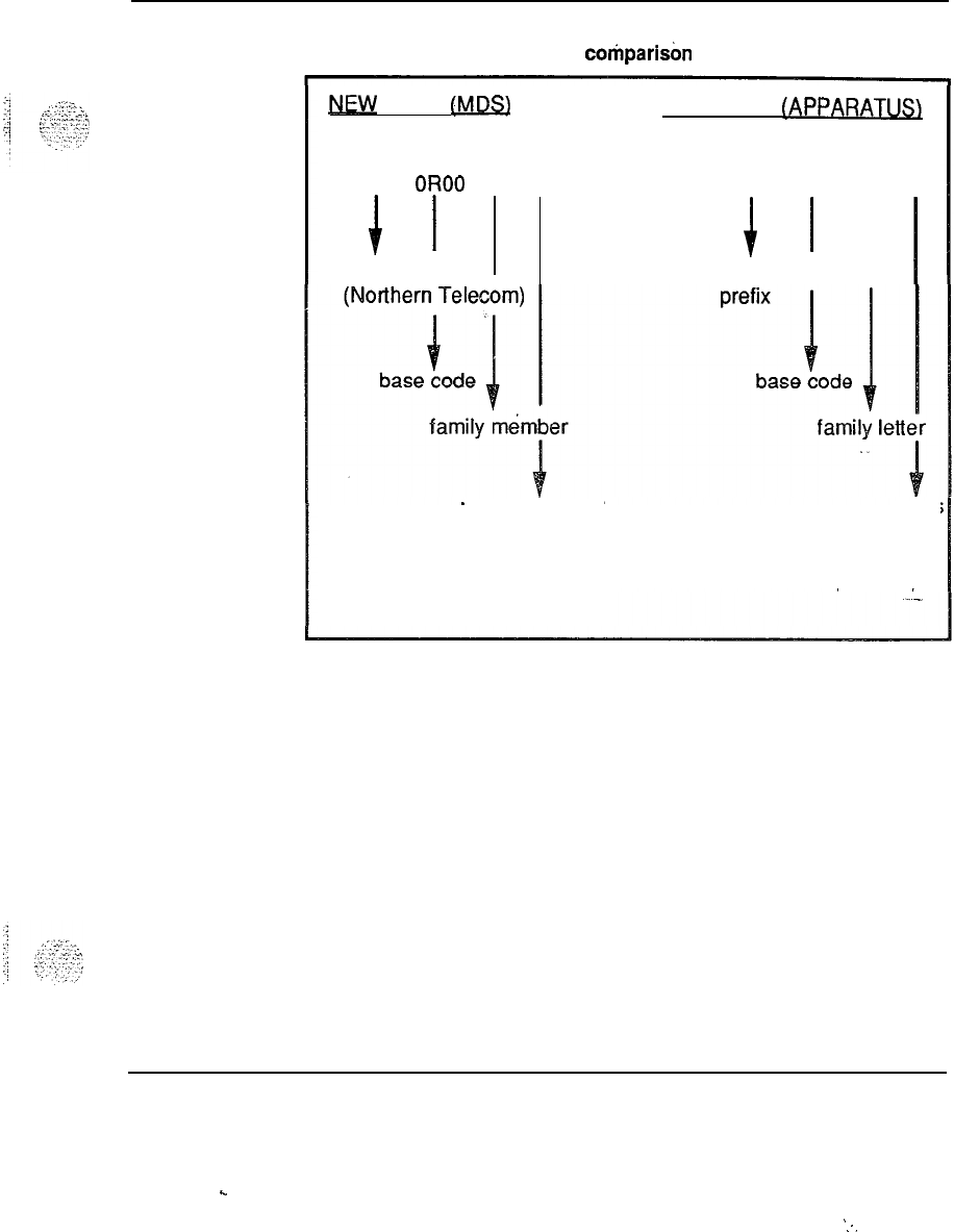
General 3
Figure l-l
Modular and apparatus coding cohparisbn
MW
CODE
(MDS) QLD CODE
IAPPARATUS\
NT
OR00
AA 01
I
I
fixed prefix
QPC 123 A A
1
1 I
SL-1 circuit pack
release number series
553-3046
Equipment identification and ordering information 553-3001-154
.
.
.
:.

4 General
Equipment identification and ordering information 553-3001-l 54
.
.
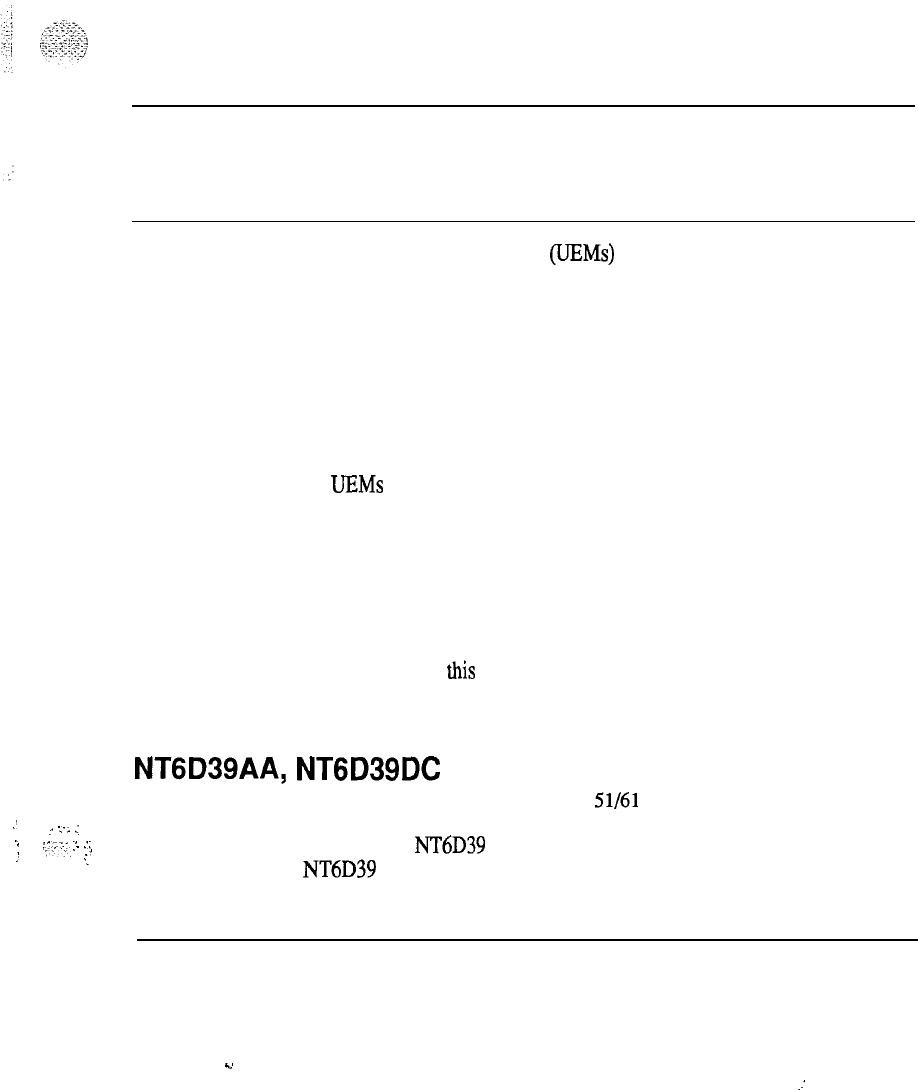
5
Universal Equipment Modules and
packaging
_, .~
:-
.:
..
:-.:._
;.
.;,,
_.‘;,
_I
:
._
Universal Equipment Modules (UEMs) are self-contained equipment
modules which house system components such as card cages, circuit cards,
power units, mass storage units, and cabling.
Each UEM is approximately 80 cm (31.5 in.) wide, 52.1 cm (20.5 in.) deep
(55.9 cm (22.0 in.) with covers), and 43.2 cm (17 in.) high. The weight of a
UEM is approximately 21.8 kg (48 lbs) empty, including the top, bottom,
sides, side trim panels, card cage, Input/Output (I/O) panel, and
miscellaneous hardware.
All UEMs are equipped with a card cage assembly and a cover assembly.
Refer to
Circuit puck installation and testing
(553-3001-211) for the
identification and location of the different cards within each UEM.
A UEM that is populated with various hardware components is referred to
as a module. The different types of modules available are described in this
chapter.
Also described in this chapter are the main components of a system option
which can be ordered as a separate package. These components are the Top
Cap, the card cages, the pedestal, the Spacer Kit, and the Module Covers.
NT6D39AA,
NT6D39DC
CPU/Network Module
System hardware-System
option 51/61
Purpose-The
NT6D39 CPU/Network Module (hereafter referred to as
NT6D39 CPU/NET) houses a Central Processor Unit (CPU) and network
cards.
Equipment identification and ordering information 553-3001-154
s.
.:
6Universal Equipment Modules and packaging
This module is available in two versions:
-
NT6D39AA for AC systems
-
NT6D39DC for DC systems
The NT6D39 CPU/NET card cage contains 18 card slots which support the
following:
-
network cards
-
Clock Controller
-
Serial Data Interface (SDI)/Enhanced Serial Data Interface (ESDI)
-
Peripheral Signaling
-
3-Port Extender (3PE)
-
mass storage unit
-
CPU Function
-
CPU Interface
-
Changeover Memory Arbitrator (CMA)
-
Memory
-
D-Channel Handler Interface (DCHI)
-
Primary Rate Interface (PRI)/Digital Trunk Interface (DTI)
The NT6D39 CPU/NET Module is powered by a Common Equipment
Power Supply.
Quantity-One per System option 51 system; two per System option 61
system
NT6D44AA, NT6D44DC Meridian Mail Module
System hardware-System option
21/51/51/71
Purpose-The
NT6D4l
Meridian Mail Module is a self-contained unit,
complete with power converters and cooling units. It is designed to
integrate with Meridian 1 Communication Systems but is also available as a
stand-alone system.
This module is available in two versions:
Equipment identification and ordering information 553-3001-154
.u
:
.
.
Universal Equipment Modules and packaging 7
-
NT6D44AA
for AC systems
-
NT6D44DC for DC systems
The Meridian Mail Module is powered by two Common Equipment Power
Supplies.
Refer to the Meridian Mail suite of documents (553-7041-xxx) for detailed
information.
Quantity-Maximum of five per system
NT8Dll
AC,
NT8Dll
DC CE/PE Module
System
hardwareSystem
option 21 and 21A
Purpos+The
NT8Dll
Common/Peripheral Equipment Module (hereafter
referred to as
NT8Dll
CE/PE) supports CPU, network, and Intelligent
I.
Peripheral Equipment (IPE) cards in a single module.
This module is available in two versions:
-
NT8DllAC
for AC systems
-
NT8DllDC
for DC systems
.-
The
NT8Dll
CE/PE card cage contains 20 card slots which support the
following:
-
Floppy Disk Interface (FDI)/Floppy Disk Unit (FDU)
-
CPU
-
Memory
-
SDI/ESDI
-
network
-
network/Digitone
Receiver (DTR)
-
DCHI
-
DTI/PRI
-
IPE
Equipment identification and ordering information 553-3001-l 54
8Universal Equipment Modules and packaging
The
NT8Dll
CE/PE Module is powered by a Common/Peripheral
Equipment (CE/PE) Power Supply.
Quantity-One per system
NT8D13AA, NT8D13DC Peripheral Equipment Module
System
hardwareSystem
option
21/51/61/71
Purpose-The
NT8D13 Peripheral Equipment Module (hereafter referred
to as NT8D13 PE) supports the Dual Loop Buffer (DLB), and 10 card
slotsThe
PE Buffer is situated near the center of the module, with five cards
to the left and five cards to the right.
This module is available in two versions:
-
NT8D13AA for AC systems
-
NT8D13DC for DC systems
I.
The NT8D13 PE Module is powered by a Peripheral Equipment Power
Supply, and a Ringing Generator when 500/2500 sets are supported by the
module.
Quantity-As
required; refer to
System engineering
(553-3001-151)
.-
NT8D34AA, NT8D34DC CPU Module
System hardware-System
option 71
Purpose-The
NT8D34 CPU Module (hereafter referred to as NT8D34
CPU) houses the CPU, memory cards, and the mass storage.
This module is available in two versions:
-
NT8D34AA for AC systems
-
NT8D34DC for DC systems
The NT8D34 CPU card cage contains 15 card slots which support the
following:
-
Memory
-
CMA
Equipment identification and ordering information 553-3001-154
v
,
Universal Equipment Modules and packaging 9
-
CPU Interface
-
MS1
-
Segmented Bus Extender (SBE)
-
DCHI
-
PRI/DTI
-
Clock Controller
-
Mass Storage Unit (MSU) or Floppy Disk Unit (FDU)
The NT8D34 CPU Module is powered by a Common Equipment Power
SUPPlY
*
I.
Quantity-Two per system
NT8D35AA, NT8D35DC Network Module
System hardware-System
option 71
Purpose-The
NT8D35 Network Module (hereafter referred to as NT8D35
NET) provides the signal interface between the Common Equipment (CE)
cards located in the module.
This module is available in two versions:
-
NT8D35AA for AC systems
-
NT8D35DC for DC systems
The NT8D35 NET card cage contains 15 card slots which support the
following:
-
3PE
-
Intergroup Switch (IGS) (for System option 71 only)
-
peripheral signaling
-
network cards
-
SDI/ESDI
Equipment identification and ordering information 553-3001-l 54
10 Universal Equipment Modules and packaging
-
PFu/DTl
The NT8D35 NET Module is powered by a Common Equipment Power
S”PPlY.
Quantity-A
maximum of 10 per system (five network groups)
NT8D36AA Inter Group Module
System hardware--System
option 71
Purpose-The
NT8D36AA Inter Group Module provides a path for the
switching of traffic between the network groups in the system. Faceplate
cables from the Clock Controller (CC) and Intergroup Switch (IGS) circuit
cards are connected to the Inter Group Module. This module uses a
QFC417 Junctor Board.
This module is used in both AC and DC systems.
Quantity--One per
system
NT8D37AA, NT8D37DC Intelligent PE Module
System hardware-System option 21/51/61171
Purpose-The
NT8D37 Intelligent Peripheral Equipment Module
(hereafter referred to as NT8D37 IFE) supports a Controller card and 16
IFE cards. The Controller card is situated near the center of the module,
between slot 7 and slot 8.
This module is available in two versions:
-
NT8D37AA for AC systems
-
NT8D37DC for DC systems
The card slots in the NT8D37 IPE card cage support the following:
-
Universal Trunk
-
E&MTrunk
-
Digitone
Receiver
-
Analog Line card (ALC)
..
.
‘:I-.
:
,.!I
.
Equipment identification and ordering information 553-3001-154

Universal Equipment Modules and packaging
11
-
Digital Line card (DLC)
-
Analog Message Waiting Line card (MLC)
The NT8D37 IPE Module is powered by a Peripheral Equipment Power
Supply, and a Ringing Generator when 500/2500 sets are supported by the
module.
Quantity-As
required; refer to System engineering (553-3001-151)
.:
:
NT8D47AA, NT8D47DC Remote PE Module
System hardware-System
option 21/51/61/71
Purpose-The
NT8D47 Remote Peripheral Equipment Module (hereafter
referred to as NT8D47 RPE) is an interface module used to extend the
interconnection distance between local and remote sites.
The same module is used for both local and remote applications.
‘On
the
local side, it interfaces to the QPC4 14 Network card for up to two network
loops; on the remote side, it supports the NT8D13 PE Module.
This module is available in two versions:
-
NT8D47AA
for AC systems
-
NTfD47DC
for DC systems
The NT8D47 RPE card cage contains 12 card slots which support the
following:
-
1.5 Mb converter
-
2 Mb converter
-
carrier interface
-
remote peripheral
-
local carrier buffer
-
carrier interface
-
2 Mb converter
-
1.5 Mb converter
-
carrier maintenance
Equipment identification and ordering information 553-3001-154
12 Universal Equipment Modules and packaging
I
-
PRI/DTI (optional)
The NT8D47
WE
Module is powered by a Common Equipment/Peripheral
Equipment Power Supply.
Quantity-Since each NT8D47
WE
Module serves two network loops, the
number of modules required per system depends on the number of stations
in the remote site.
NT8D49 Spacer Kit
System Hardware-All
Purpose-Bolts modules together for side-by-side expansion. The Spacer
Kit includes:
-
expansion spacer
-
RF
gasketing
-
eight bushings
NT8D55AA Universal Equipment Module cover
System Hardware-All
Purpose-This
is the front or rear cover that is part of the UEM. Two
covers are required for each UEM.
Universal Equipment Module side panel
System Hardware-All
Purpose-This is the side panel (PO699724) that is part
of the UEM.
A
maximum of eight panels are required for multi-column systems.
Card cage assemblies
A card cage assembly consists of a sheet metal case and an associated
backplane. The card cage provides the physical framework that houses the
circuitry and power supplies within the UEM.
The following is a list of all the card cage assemblies available and their
corresponding UEMs:
Equipment identification and ordering information 553-3001-154
.
.
Universal Equipment Modules and packaging 13
.
.
:.:
.:
.,..
I..
1..,.
‘.’
;:-..:
:
-
NT6D3903 NT6D39AA/DC CPU/Network Module
-
NT8D1103
NT8Dl
lAC/DC
Common/Peripheral Equipment
Module
-
NT8D1303 NT8D13AA/DC Peripheral Equipment Module
-
NT8D3403 NT8D34AA/DC CPU Module
-
NT8D3503 NT8D35AA/DC Network Module
-
NT8D3703 NT8D37AA/DC Intelligent Peripheral Equipment
Module
-
NT8D4703 NT8D47AA/DC Remote Peripheral Equipment
Module
Top Cap
System Hardware-All
I.
Purpose-The
top cap is mounted on the highest module of each column.
The top cap is approximately 80 cm (31.5 in.) wide by 55.9 cm (22 in.) deep
by 7.6 cm (3 in.) high and weighs 3.6 kg (8 lbs). It consists of a front and a
rear air exhaust grill and thermal sensors. System option 21A contains a
small fan to cool the power supply.
.-
Three versions of the top cap are available:
-
Nl7DOOAA AC systems
-
NT7DOOBA DC systems
-
NT7DOOAC System option 21A only
Pedestal
System Hardware-All
Purpose-The
Pedestal is a base unit made of die-cast construction. It is
approximately 80 cm (31.5 in.) wide by 64.8 cm (25.5 in.) deep by 25.4 cm
(10 in.) high and weighs 13.6 kg (30 lbs) empty. Leveling feet are provided
for up to four tiers, while a caster option is provided for up to two tiers.
The pedestal is available in three versions:
-
NT8D27AB for AC systems
Equipment identification and ordering information 553-3001-154
2.
.-
.
.
14 Universal Equipment Modules and packaging
:,i,
-
NT8D27AC for System option’21A only
-
NT7DO9AA for DC systems
The pedestal for AC and DC systems (except System option 21A) can
house any of the following field replaceable assemblies:
-
Power Distribution Unit
NT8D53AB or
NT7DlOAA
-
Blower Unit
NT8D52A.A or NT8D52DC
-
Fan Unit
NT7D17AC or NT7D17DC
-
Leveling foot
A03 18207
-
Air grill (molded)
PO699797
-
Air filter
PO699798
The pedestal for System option 21A is basically the same as the one used
for other system options except it can only house the following field
.-
replaceable assemblies:
-
Power Distribution Unit
NT8D53AD
-
Leveling foot
A03 18207
-
Air grill (molded)
PO699797
Equipment identification and ordering information 553-3001-154
s.
15
Power and cooling equipment
A0367754 Top Cap Fan
System Hardware-System option 21A
Purpose-The A0367754
Top Cap Fan is
located in the
Fan and Sensor
Panel. It provides cooling for the NT7D14AA CE/PE power Supply AC.
There is no speed or temperature control provided with it. Power. to the Top
Cap Fan is controlled by the circuit breaker located on the back panel of the
pedestal.
Quantity-One per system
NTSC03BJ Switched Mode Rectifier -48V/50A
_-
System Hardware-System option 71 (DC version)
Purpose-Solid
state, switched-mode rectifier. Converts 208/240 VAC
(nominal) to -48 VDC (nominal), with a 50A output. Used in the QCA13
power plant, with up to ten rectifiers in parallel.
Quantity-As required by system power consumption
NT6D40AA Peripheral Equipment Power Supply DC
System Hardware-All
Purpose-The
Peripheral Equipment Power Supply DC is used to provide
power to all peripheral equipment modules in DC systems. It converts -48V
DC to +5V, +8.5V,
+lOV,
+15V, and -48V DC voltages used to power
peripheral equipment logic cards and to supply talk battery to lines and
trunks. This power supply is located in the far left hand card slot labeled
“PE Pwr Sup”.
Equipment identification and ordering information 553-3001-154
.
.
16 Power and cooling equipment
Quantity--One
Peripheral Equipment Power Supply DC is used in each of
the following DC modules:
-
Intelligent Peripheral Equipment Module (NTSD37DC)
-
Peripheral Equipment Module (NT8Dl3DC)
NT6D41AA Common Equipment Power Supply DC
System Hardware-All
Purpos-The
Common Equipment Power Supply DC is used in the
common equipment modules in DC systems. It is located in the first slot on
the left in the module labeled “CE Pwr Sup”. It converts -48V DC to +5V
and
f12
V DC to provide all required voltages for CE and network circuit
cards.
Quantity-One Common
Equipment Power Supply DC is used in each of
the following DC modules:
_.
-
CPU Module
(NT8D34DC)
-
Network Module
(NT8D35DC)
-
CPU/Network Module
(NT6D39DC)
Two Common Equipment Power Supply DC is used in the Meridian Mail
.-
Module
(NT6D44DC).
NT6D52AA Switched Mode Rectifier -48W30A
System Hardware-System
option 21/51/61 (DC versions)
Purpose-The
Switched-Mode Rectifier is a QRF12 rectifier shielded to
limit electromagnetic interference. It converts 208/240 VAC (nominal) to
-
48 VDC (nominal), with a 30A output. It connects to the system through
the
QBLl5
Battery Distribution Box.
Quantity-Generally
one rectifier per every two fully loaded modules.
Exact quantity depends on system configuration and power requirements.
Equipment identification and ordering information 553-3001-154
.
.
Power and cooling equipment
17
NT6D53AA Junction Box
System Hardware-All (DC
version)
Purpose-The
Junction Box is
required
when the distance from the rectifier
to the pedestal is over 0.74 m (8 ft), which requires wire larger than 10
AWG. It provides a set of connection terminals for the 4-AWG wire that
comes from the rectifier, and a set of connection terminals for the
lo-AWG
wire that goes into the pedestal.
Refer to
Power
engineering (553-3001-152) for more information.
Quantity--&e
per DC pedestal
NT6D5303 Logic Return Equalizer
System Hardware-System
option 71 (DC version)
Purpose-The
Logic Return Equalizer (LRE) mounts on top of the QCA13
cabinet. It is used as the single point ground for System option 7 1.
Quantity--One per system
NT7D0003 Fan and Sensor Panel
System Hardware-System
option 21A
Purpose-The
NT7DOOO3
Fan and Sensor Panel contains a 230 VAC
tubeaxial fan (A0367754) and a thermal sensor for a high
temperature/shutdown alarm to the option 21A System Monitor. The fan
provides cooling for the NT7D14AA Common/Peripheral Equipment Power
Supply. It is on continously and receives power directly from the Power
distribution Unit via the module power harness.
The N’l7DOOO3 Fan and Sensor Panel consists of the following:
-
a perforated top shield (PO703062)
-
a Top Cap Fan (A0367754)
-
a fan power harness
(NT7DOOO4)
-
a thermostat harness (NT8D46AC)
Quantity--One
per system
Equipment identification and ordering information 553-3001-154
.
.
18 Power and cooling equipment
NT7D03AA Ringing Generator DC
System Hardware-All
Purpose-The
Ringing Generator DC operates from a nominal -48V DC
input and provides selectable AC ringing voltage outputs superimposed on
-48 VDC. The frequency and voltage options are-20/25/50 Hi and 70/80/86
VAC. It also supplies -150V DC Message Waiting lamp 500/2500 set
applications. The Ringing Generator DC mounts in the PE modules to the
right of the Peripheral Equipment Power Supply DC.
Quantity--One
Ringing Generator DC is used in each of the following,
when these DC modules support 500- or 2500~type analog sets:
-
Intelligent Peripheral Equipment Module (NT8D37DC)
-
Peripheral Equipment Module (NT8Dl3DC)
NT7D04AA CE/PE Power Supply DC
System Hardware-All
(DC versions)
Purpose-The
Common/Peripheral Equipment Power Supply DC converts
-48V DC to +5V, +8.5V, +15V, +12V,
48V,
and -150V DC voltages used
to power peripheral and common equipment, supply talk battery, and light
Message Waiting lamps on 500/2500 sets. It provides selectable AC
.-
ringing voltage outputs superimposed on -48 VDC. The frequency and
voltage options are 20/25/50 Hz and 70/80/86 VAC. It is located to the left
of the module, in the slot labeled “CE/PE Pwr Sup”.
Quantity-One
Common/Peripheral Equipment Power Supply DC is used
in each of the following DC Modules:
-
Common/Peripheral Equipment Module (NT8D 11DC )
-
Remote Peripheral Equipment Module
m8D47DC)
NT7DlOAA Power Distribution Unit DC
System Hardware-All
Purpose-The
NT7DlOAA Power Distribution Unit DC distributes power
to the entire column. It is located in the rear of the pedestal. It houses five
circuit breakers (one for each Module and one for the Blower Unit) and the
System Monitor.
Equipment identification and ordering information 553-3001-154
.
.
Power and cooling equipment 19
Quantity-One
p&pedestal/column in DC systems
NT7D12AA
Rectifier Rack
System
Hardware-21/51/61
(DC versions)
Purpose-This
is a 48.3-cm (19-in.) open relay rack which is
approximately 1.5 m (5 ft) high. It supports up to three NT6D52AA
Rectifiers in a single column.
Quantity-One rack per every three
NT6D52.44
Rectifiers, up to a
maximum of three racks per system
NT7D14AA
CE/PE
Power Supply AC
System Hardware-All
Purpose-The Common/Peripheral Equipment
Power Supply AC converts
208/24OV AC to +5V, +8.5V, +15V, +12V,
48V,
and -150V DC voltages
used to power peripheral and common equipment, supply talk battery, and
light Message Waiting lamps on 500/2500 sets. It provides selectable AC
ringing voltage outputs superimposed on -48 VDC. The frequency and
voltage options are 20/‘25/50 Hz and 70/80/86 VAC. It is located to the left
of the module, in the slot labeled “CE/PE Pwr Sup”.
Quantity-One
Common/Peripheral Equipment Power Supply AC
isused
in each of the following AC modules:
-
Common/Peripheral Equipment Module (NTSDl 1AC)
-
Remote Peripheral Equipment Module (NT8D47AA)
NT7D15AA
System Monitor
-
System option
21A
System Hardware-System
option 21A
Purpose--The
NT7DlSAA
System Monitor
-
System option 21A provides
an interface to communicate and monitor the NT7D14AA CE/PE Power
Supply AC, the CPU, and the thermal switches. In the event of failure, the
System Monitor
-
System option 21A is notified and the appropriate alarm
is set. A system alarm LED located below the top cap lights to indicate
CPU failure.
Quantity-One per
system
Equipment identification and ordering information 553-3001-154
20 Power and cooling equipment
NT7D17AC Fan Unit AC
-
System Hardware-System
option 21 with up to two tiers
Purpose-The
NT7D17AC Fan Unit AC is housed within the pedestal and
provides cooling for the entire column. It consists of three fans and a circuit
breaker located in the front.
Quantity-One per pedestal
NT7D17DC Fan Unit DC
System Hardware-System option 21 with up to two tiers
Purpose-The
NT7D17DC Fan Unit DC is the same as the NT7D17AC
Fan Unit AC except that it is used for DC systems. It has an on/off switch
in the front and its own separate circuit breaker located on the Power
Distribution Unit.
Quantity--One per pedestal
NT7D1201
Rectifier Baffle/Mounting Kit
System Hardware-System option 21/51/61
(DC versions)
Purpose-The
Rectifier Baffle/Mounting Kit consists of a set of support
.-
brackets for mounting the NT6D52AA Rectifier to an NT7D12AA Rack,
and a heat baffle plate. The baffle directs exhaust air from the lower
rectifier away from the inlet to the upper rectifier, thereby allowing cooling
by natural convection.
Quantity-One per
NT6D52AA Rectifier
NT8DOGAA
Peripheral Equipment Power Supply AC
System Hardware-All
Purpose-The
Peripheral Equipment Power Supply AC is used to provide
power to all peripheral equipment modules in AC systems. It converts
208/24OV AC to +5V, +8.5V,
+lOV,
+15V, and -48V DC voltages used to
power peripheral equipment logic cards and to supply talk battery to lines
and trunks. This power supply is located in the far left-hand card slot
labeled “PE Pwr Sup”.
Equipment identification and ordering information 553-3001-154
Power and cooling equipment
21
Quantity--One
Peripheral Equipment Power Supply AC is used in each of
the following AC modules:
-
Intelligent Peripheral Equipment Module (NT8D37AA)
-
Peripheral Equipment Module (NT8D13AA)
-
NT8D21AA
Ringing Generator AC
System Hardware-All
Purpose-The
Ringing Generator AC operates from a nominal 208/240
VAC input and provides selectable AC ringing voltage outputs
superimposed on -48 VDC. The frequency and voltage options are
20/25/50 Hz and 70/80/86 VAC. It also supplies -15OV DC Message
Waiting lamp 500/2500 set applications. The Ringing Generator AC
mounts in the PE modules to the right of the Peripheral Equipment Power
SUPPlY.
Quantity-One
Ringing Generator AC is used in each of the following,
when these AC Modules support 500- or 2500~type analog sets:
-
Intelligent Peripheral Equipment Module (NT8D37AA)
-
Peripheral Equipment Module
(NT8D13AA)
.-
NT8D22AB
System Monitor
System Hardware-All
except System option 21A
Purpose-The
NT8D22AR System Monitor monitors the status of
ail
internal power and cooling related components, as well as external DC
rectifiers, batteries, and Uninterruptable Power Supplies (UPS). The
System Monitor is mounted in the Power Distribution Unit, within the
Pedestal.
The System Monitor that handles the communication with the system CPU
(via SD1 port) is the master; all others function as slaves. There is a serial
communication link between the master and the slave System Monitors. In
addition to CPU status reporting, the System Monitor also controls all
external visual status indications.
Quantity-One
master and up to 63 slave System Monitors are allowed per
system.
Equipment identification and ordering information 553-3001-154
..
22 Power and cooling equipment
NT8D29AA Common Equipment Power Supply AC
System Hardware--System
option
51/61/71
Purpose-The
Common Equipment Power Supply AC is used in the
common equipment modules in AC systems. It is located in the first slot on
the left in the module labeled “CE Pwr Sup”. It converts 208/24OV AC to
+5V
and
f12
V DC to provide all required voltages for CE and network
circuit cards.
Quantity-One Common Equipment Power Supply AC is used in each of
the following AC Modules:
-
CPU Module
(NT8D34AA)
-
Network Module
(NT8D35AA)
-
CPU/Network Module
(NT6D39AA)
Two Common Equipment Power Supply AC is used in the Meridian Mail
Module
(NT6D44AC).
NT8D39AA Power Failure Transfer Unit
System Hardware-All
Purpose-Provides an interface between CO lines, Private Branch
.-
Exchange (PBX), and 500/2500 phones (rotary dial and pushbutton). The
Power Failure Transfer Unit allows eight phones to be connected to the CO
lines in the event of a PBX power failure or malfunction. The Power Fail
Transfer Unit is invisible to the switch and CO lines during normal PBX
operations.
The Power Fail Transfer Unit is approximately 22.8 cm (9 in) long by 22.8
cm (9 in) wide by 8.8 cm (3.5 in) deep. It is screw-mounted to the
Distribution Frame and connects to the Main Distribution Frame and switch
by two 25-pair cables.
Note:
The Power Fail Transfer Unit is not recommended for use in
international applications.
Quantity-One
per system
Equipment identification and ordering information 553-3001-154
C.
Power and cooling equipment 23
‘.
.
2.::.
:;
i
..,,-_.
,.:i
NT8D52AA Blower Unit
-
System Hardware-All
Purpose-The
Blower Unit is part of the system cooling assembly and
provides forced-convection cooling. Housed within the pedestal, it contains
two backward-curved impellers (rotor blades) which are cylindrically
shaped, approximately 22.8 cm (9.in) in diameter, and 6.9 cm (2.75 in)
thick.
A
circuit breaker is located on the front of the blower chassis to turn
the unit on and off. Each unit weighs about 1.5 kg (3.5 lbs).
The unit communicates with the power distribution section by engaging a
connector in the rear of the pedestal.
Quantity-One per pedestal in AC systems
NT8D52DC Blower Unit
System Hardware-All
Purpos+This
Blower Unit is the same as the NT8D52AA Blower Unit
except that it is used for DC systems. It has its own separate circuit breaker
located on the Power Distribution Unit. Also, for maintainability in the
field, a switch is located on the front of the blower chassis to turn the unit
on and off.
.-
Quantity-One per pedestal
in DC systems
NT8D53AB Power Distribution Unit AC
System Hardware-All
Purpose-The
Power Distribution Unit AC distributes power to the entire
column. It is located in the rear of the pedestal. It houses a main circuit
breaker and the System Monitor.
Quantity-One
per pedestal/column in AC systems
Equipment identification and ordering information 553-3001-154
s.
. . . .
:.
.-
-.
24 Power and cooling equipment
NT8D53AD Power Distribution Unit
-
System option 21A
System Hardware-System
option 21A
Purpose--The
Power Distribution Unit
-
System option 21A is a panel
located in the pedestal. It contains a circuit breaker, a terminal block, and
an EM1 filter. The power cable enters the pedestal and connects to the
circuit breaker. From the circuit breaker, the AC voltage goes to the
terminal block through the EM1 falter and back to the terminal block where
it is distributed to the NT7D 14AA CE/PE Power Supply AC and the fan
located in the top cap.
Quantity-One
per system
NT8D56AA Module Power Distribution Unit
System Hardware-All
Purpose-The
NTSD56AA’Module Power Distribution Unit protects the
power supply and distributes power within a module. It houses a single
breaker and is used in conjunction with the NT8D29AA CE Power Supply
AC.
Quantity--One
per NT8D35AA NET, NT6D39AA CPU/NET, or
NT8D34AA CPU Module
.-
NT8D56AB Module Power Distribution Unit
System Hardware-All
Purpose-The
NTSD56Al3 Module Power Distribution Unit protects the
power supply and distributes power within a module. It houses a single
breaker and is used in conjunction with the NT7D14AA CE/PE Power
Supply AIC.
Quantity-One
per NT8D47AA
WE
Module
NT8D57AA Module Power Distribution Unit
System Hardware-All
Purpose-The
NT8D57AA Module Power Distribution Unit protects the
power supply and distributes power within a module. It houses a dual
Equipment identification and ordering information 553-3001-154
Power and cooling equipment 25
breaker and is use&in conjunction with the NT8DO6AA PE Power Supply
AC and the NTSD21AA Ringing Generator AC.
Quantity-One per
NTSD13AA
PE or
NT8D37AA
IPE Module
NT8D62AA, NT8D62DC Temperature Sensor Panel
System Hardware-AN
except System option 21A
Purpose-The
NT8D62 Temperature Sensor Panel communicates with the
System Monitor in the event of overheating. It contains hvo temperature
sensors which protect against the.rmal damage by detecting extreme
temperature.
The Temperature Sensor Panel is available in two versions:
-
NT8D62AA for AC systems
-
NT8D62DC for DC systems
The Temperature Sensor Panel consists of the following:
-
a perforated shield panel (PO703062)
-
an LED bracket (PO703061)
-
a thermostat harness (NT8D46AC)
-
an air probe harness (NT8D46AM or NTSD46DC)
-
an air probe connector bracket (PO703064 or PO708 186)
Quantity-One
per top cap
QBLI 2 Battery Distribution Box
System Hardware-All
(DC versions)
Purpose--Connects
customer-provided power supplies to the system.
Allows connection of up to 24 modules.
Quantity-One per system
.-
Equipment identification and ordering information 553-3001-154
..:
‘..
26 Power and cooling equipment
QBLI 5 Power/Battery Distribution Box.
System Hardware-System
option 21/51/61 (DC versions)
Purpose-Allows the
parallel connection of up to three NT6D52AA
Rectifiers, for connection to the system and to reserve batteries. Includes
main fuses, diode blocking, test points, QPC188 battery monitor card, and
sense lead fusing on connections from each rectifier.
Quantity-One
per every three NT6D52AA Rectifiers, up to a maximum
of two
QBLlSs
per system
QCA13 DC Power Plant
System Hardware-System
option 71 (DC version)
Purpose--Consists
of a primary power cabinet with fusing and distribution
hardware, monitoring and control, and up to four NT5CO3 50A Rectifiers.
Up to two supplemental cabinets can be added, with up to four rectifiers.in
the first supplemental cabinet and up to two rectifiers in the second cabinet,
for a total of 10 rectifiers and a total system capacity of 500A. (This power
system is also referred to as the J2412 power plant; QCA13 is actually the
cabinet designation, but is the more commonly used name.)
Quantity-As
required by system power consumption
QPCI 88 Battery Monitor
System
Hardwar-All
Purpose-Located in each Battery Distribution Box to monitor rectifier and
battery voltages. Generates low float alarm, low voltage trip alarm and
sense lead fuse conditions.
Quantity-One circuit
card in QBL12 or
QBLl5
Equipment identification and ordering information 553-3001-154

Power and cooling equipment 27
QRF12
-52 V Rectifier
-
System Hardware--System
option
21/51/61
(DC version)
Purpuse-Converts
115 V AC and 220 V AC to -52 V DC (nominal).
QFW12B voltage conversions from 9OV to 129V, and
l?OV
to 25OV.
Connects to the columns through the
QBLi5
Power/Battery Distribution
Box.
Quantity-One for every two modules
Equipment identification and ordering information
553-3001-154

28 Power and cooling equipment
Equipment identification and ordering information 553-3001-154
29
Common Equipment cards
NT8D04AA Super-loop Network
System Hardware-All
Purpose-
Provides 120 time slots (one superloop) interface between
Network and Intelligent Peripheral Equipment. Utilizes the equivalence of
four network loops. May be connected to one or two NT8DOl Controller
card(s).
The Superloop Network card is equipped with a Motorola 68000~type
microprocessor which performs network diagnostics and signaling control,
and communicates with the Intelligent Peripheral Controller.
Quantity-As required. Refer to System engineering
(553-3001-15l);or
engineering details.
NT8D17AA Conference/lone and Digit Switch (TDS)
System
Hardwart+All
Purpose-Provides both Conference and TDS functions. This card
accesses two network loops, one for each function.
The Conference circuitry has a warning tone option and supports broadcast
mode. Up to 15 simultaneous conferences can be controlled with the
restriction that the total number of conferees in all conferences is not greater
than 30.
The TDS circuitry provides tones for different countries (up to 256 tones
and cadences).
Equipment identification and ordering information 553-3001-154
30 Common Equipment cards
Quantity-As required.
R&fer
to System engineering (553-3001-151) for
engineering details.
NT8Dl8AA
NetworWDigitone Receiver
System Hardware-System
option 21 and 21A
Purpose-Combines the functionality of the Network Controller and
Digitone
Receiver cards in a mother/daughterboard assembly. The
motherboard plugs into a dedicated slot on the backplane. The
daughterboard attaches to the motherboard through an SDI/ESDI connector
and does not connect to the backplane.
Quantity--One
per
NT8Dll
CE/PE Module
NT8D19AA Memory/Peripheral Signaling
System Hardware-System
option 21 and 21A
Purpose-Combines
the functionality of the Memory and Peripheral
Signaling cards, as well as miscellaneous CPU functions.
The CPU functions include interrupt and fault monitoring.
The Peripheral Signaling function provides:
.-
-
signaling interface between CPU and Peripheral Equipment for up to 32
network loops
-
clock and timing signals for real-time transmission functions
Quantity--One per
NTSDl
1 CE/PE Module
NT8D41AA Serial Data Interface paddle board (Dual Port)
System Hardware-System option 21/51/61
Purpose-Provides two serial ports between the
SL-1
processor and an
external device. Each port supports
-
RS-232-C interface
-
g-bit ASCII data with parity and stop bit
-
asynchronous, start-stop operation
Equipment identification and ordering information 553-3001-154
..d
Common Equipment cards
31
-
data rates of
300,600,1200,2400,4800,
and 9600 baud
-
Data Terminal Equipment (DTB) mode
-
Data Communication Equipment (DCE) mode
Quantity-Three
maximum per
NT8Dl
lCE/pE
Module; two maximum
per NT6D39 CPU/NET Module
NT8D68AA
Floppy Disk Unit
System
hardwareSystem
option 21/51/61/71
Purpose--The
Floppy Disk Unit (FDU) is used to load the programs and
office data into the system memory. The FDU contains two 3.5~inch floppy
drives and is controlled by the QPC742 Floppy Disk Interface (PDI). Each
floppy drive has a formatted capacity of 1.44 MB.
The FDU occupies two adjacent card slots in the CPU, Network, or PE
Module. It is powered through the cable connecting it to the FDI. The FDU
can be connected to one or two FDIs as required by the system.
Quantity-One per system
NT8D69AA
Multi Disk Unit
.-
System hardware-System
option 51/61/71
Purpose-The
Multi Disk Unit (MDU) is used to load the programs and
office data into the system memory. The MDU contains the following:
-
two 3.5-inch floppy drives which are connected to the SCSI interface
through the SCSI/floppy controller; each drive has a formatted capacity
of 1.44 MB
-
a 3.5-inch hard disk drive which has a built-in SCSI interface and a
capacity of 20 MB
-
an SCSI/floppy controller
The MDU occupies three adjacent card slots in the CPU, CPU/NET, or
Network Module and requires 5V and 12V from the module. The MDU is
controlled by the QPC584 Mass Storage Interface (MSI). The MDU can be
connected to one or two MSIs as needed.
Equipment identification and ordering information 553-3001-154
32 Common Equipment cards
..
Quantity-One per systeui
j
QMM42 Security Data Cartridge
.i
System Hardware-All
Purpose-This is a security measure that allows a customer access only to
software packages purchased for his system. This security data cartridge is
mounted on either the QPC584 Mass Storage Interface or QPC742 Floppy
Disk Interface card.
Quantity-One per
MSI/FDI card
QPC43 Peripheral Signaling
System Hardware-System option 51/61/71
Purpose--Provides
a signaling interface between the CPU and PE via the
Network cards. Provides basic bit rate 2.048 MHz clock and timing signals
for real-time functions.
Quantity--One
per NT8D35 NET or NT6D39 CPU/NET Module
QPC215 Segmented Bus Extender
System Hardware-System option 71
-.-
Purpose-The
Segmented Bus Extender (SBE) extends CPU bus signals
(address, data, and control) to the Network Module. It also allows recovery
of calls by isolating bus faults to a single network group.
Note:
QPC215C or later vintage is required.
Quantityane
circuit card in each CPU per network group, with a
maximum of five per CPU
QPC412 Intergroup Switch
System Hardware-System option 71
Purpose-Provides
space switching between network groups in multigroup
systems.
Equipment identification and ordering information 5X3-3001 -154
Common Equipment cards 33
Quantity-Two pef
Network Module (use vintage C when two or more
groups are installed)
QPC414 Network
System Hardware-All
Purpuse-Provides
30 time slots interface per each of two network loops.
Provides speech path switching, signaling and control circuits for two
network loops. Interfaces between network and NT8D13 PE, NT8D47
RPE, and Meridian Mail Modules, and PRI/DTI cards,
Quantity-As
required; refer to
System engineering
(553-3001,151)
QPC417 Junctor Board
System Hardware-System
option 71
Purpose-Provides
space switching paths between network groups in
multigroup systems for up to five groups.
Quantity-One per system
QPC441 Three-Port Extender
System Hardware-System
option 61/71
.-
Purpose-Extends
CPU
data, address and control signals between one
NT8D35 NET Module and a QPC215 Segmented Bus Extender on a CPU
Module in System option 71. In System option
61,
interfaces between two
NT6D39 CPU/NET Modules.
Quantity-One per
NT8D35 NET or NT6D39 CPU/NET Module
QPC471 Clock Controller
System Hardware-All
Purpose-The
Clock Controller (CC) is used in System option 71 to
synchronize the Meridian 1 network to an external source clock and to
generate and distribute clock to the Meridian 1 system. It is also used with
PRA/DTI in all system options.
Note:
QPC471C or later vintage is required.
Equipment identification and ordering information 553-3001-154
.
.
34 Common Equipment cards
Quantity-Two
for System option 71, and one per CPU when DTI or
PU
is required in other options.
QPC477 Bus Terminating Unit
System Hardware-System
option
51/61/71
Purpose-Bus Terminating Units
(BTUs)
are installed in the CE Modules.
They provide a logical termination to the CPU and network buses. They are
paddle boards installed in dedicated slots, between circuit cards from the
front of the module.
Quantity-The
following vintages are required for the modules listed:
-
QPC477-A9
One required for each
NT6D39 CPU/NET
and each NT8D35 NET
-
QPC477-A10
One required for each
NT6D39 CPU/NET
and each NT8D35 NET
-
QPC477-A20
One required for each NT8D34 CPU
-
QPC477A21
One required for each NT8D34 CPU
-
QPC477A22
One required for each NT6D39 CPU/NET
QPC513 Enhanced Serial Data
InterFace
System Hardware-All
Purpose-Provides
two
serial data interface circuits that can be configured
for either synchronous or asynchronous data communications at rates of up
to 64 kbps (synchronous) or 19.2 kbps (asynchronous).
Note:
Use QPC5 13D with Meridian Mail option and other
applications requiring Integrated Services Digital Network (ISDN)
Application Protocol.
Quantity-As
required per application
Equipment identification and ordering information 553-3001-154
Common Equipment cards 35
QPC579
CPU Function
-
System Hardware-System option 51/61/71
Purpose--The
CPU Function card works in conjunction with the CPU
Interface card (QPCSSO). It contains the main CPU logic circuitry. The
CPU provides a 24-bit data bus. The CPU Function card contains a
QPC939 system ROM.
Quantity-One per CPU Module
QPC580 CPU Interface
System Hardware-System option 51/61/71
Purpose-Contains
the logic required to interface the CPU with the
external address bus and detects, identifies and isolates bus faults. Works in
conjunction with QPC579 CPU Function card.
Quantity-One
per CPU Module
QPC581
Changeover and Memory Arbitrator
System Hardware-System
option 51/61/11
Purpose-The
Changeover and Memory Arbitrator (CMA) card contrors
CPU access to the duplicated memory in dual CPU systems, automatically
disables faulty memory cards and controls CPU changeover. The CMA
switches from one CPU to the other in the event of a CPU fault.
Quantity-Two
CMA cards are required per system (one per CPU/Memory
configuration).
QPC583 Memory
System Hardware-System option 51/61/71
Purpose-Provides
768K of Random Access Memory (RAM).
Quantity-One per CPU for
System option 51/61; two
maximum per
System
option 71
Equipment identification and ordering information 553-3001-154
36 Common Equipment cards
QPC584 Mass Storage Interface
System Hardware-System
option 51/61/71
i
Purpose-Interface
between the Multi Disk Unit (MDU) and CPU(s).
Provides address matching, disk drive control, data buffering and interrupt
control circuits.
The MS1 is used with the MDU and contains:
-two high capacity floppy disk drives or
-one Winchester disk drive with two high capacity floppy drives as backup
Note:
QPCSS4D or later vintage is required.
Quantity-One
MS1 circuit card for each
CPUFIDU.
QPC687 CPU with SDVRTC
System Hardware-System
option 21 and 21A
Purpos+This
is a stand-alone
CPU card with error correction, real-time
clock, and one SD1 port
Note:
QPC687B or later vintage is required.
Quantity-One per system
QPC720 Primary Rate Interface
System Hardware-All
Purpose-The
ISDN Primary Rate Interface (PRI) card allows twenty three
64 Kbps clear channel operation with a single 64 Kbps common signaling
channel. It is used in conjunction with DCHI to provide PRA. The PRI
circuit card provides the physical DS-1 interface and is also used for DTI
applications.
Quantity-One
per Primary Rate Access (PRA) or DTI link
Equipment identification and ordering information 553-3001-154
..d
;
:
_.
. .
.:
Common Equipment cards 37
QPC742 Floppy Disk
Inte-rface
System Hardware-All
Purpose--interface
between the Floppy Disk Unit (FDU) and one CPU.
Provides address matching, disk drive control, data buffering and interrupt
control circuits.
Quantity-One
per CPU
QPC757 D-Channel Handler Interface
System Hardware-All
Purpose-The
D-Channel Handler Interface @CHI) card processes the
LAPD protocol for ISDN primary rate signaling channel and ISDN
Signaling Link (ISL). It also provides a single asynchronous Serial Data
Interface (SDI) port.
Quantity-One
per 16 PRI links to the same location (eight maximum per
system)
QPC841 Four-Port Serial Data Interface
System Hardware-All
-
Purpose-Provides
four serial ports between the system processor and an
external device. Each port supports
-
RS-232-C interface
-
8-bit ASCII data with parity and stop bit
-
asynchronous, start-stop operation
-
data rates of
300,600,1200,2400,4800,
and 9600 baud
-
Data Terminal Equipment (DTE) mode
-
Data Communication Equipment (DCE) mode
Quantity-Up
to four per system
Equipment identification and ordering information 553-3001-l 54

38 Common Equipment cards
QPC939 Read-Only Memory
-
System Hardware-System
option 5
l/61/71
Purpose-Read-Only
Memory @OM) daughterboard on the QPC579 CPU
Function card.
Quantity-One per
CPU
QPC940 Read-Only Memory
System Hardware-System
option 21
Purpose-ROM
daughterboard on the QPC687 CPU with SDI/RTC card.
Quantity-One per
CPU
Equipment identification and ordering information 553-3001-154
.
.
.:
I
::
39
Peripheral Equipment cards
NT8DOl AD Controller-2
System Hardware-All
Purpose-Provides
a primary interface and control function between the
Superloop Network card and the IPE Module over up to two 10.24Mbs
superloops. Each Controller-2 card serves up to 16 IPE cards.
. .
The Controller-2 card interfaces with up to two NT8DO4AA Superloop
Network cards. It is equipped with a Motorola 68000~type microprocessor
which performs some local call processing and maintenance diagnostics,
thus off-loading the system CPU.
.-
Quantity-One per NT8D37 IPE Module
NT8DOl AC Controller-4
System Hardware-All
Purpose-Provides a primary interface and control function between the
Superloop Network card and the IPE Module over up to four 10.24Mbs
superloops. Each Controller-4 card serves up to 16 IPE cards.
The Controller-4 card interfaces with up to four NT8DO4AA Superloop
Network cards. It is equipped with a Motorola 68000~type microprocessor
which performs some local call processing and maintenance diagnostics,
thus off-loading the system CPU.
Quantity-One
per NT8D37 IPE Module
Equipment identification and ordering information 553-3001-154
Y
40
Peripheral Equipment cards
NT8D02AA Digital Line card
-
System Hardware-All
Purpose--Provides
interface to up to 16 digital integrated voice and data
sets for a total of 32 ports. It is equipped with an Intel 8051-type
microprocessor which performs several functions; some of which are as
follows:
-
control of card operation
-
card identification
-
self-test
-
status reporting to the Controller
-
maintenance diagnostics
Quantity-Up to sixteen cards per
NT8D37
IPE
Module
NT8D03AB Analog Line card
System Hardware-All
Purpose-Provides interface to up to 16 analog sets (500/2500). It is
equipped with an Intel 8051~type microprocessor which performs several
--
functions, some of which are as follows:
-
control of card operation
-
card identification
-
self-test
-
status reporting to the Controller
-
maintenance diagnostics
Quantity-Up to sixteen cards per
NT8D37
IPE
Module
NT8DOSAB
Analog Message Waiting Line card
System
Hardwart+All
Purpose-Provides interface to up to 16 analog sets (500/2500) with
Message Waiting lamp feature. It is equipped with an Intel 805 l-type
Equipment identification and ordering information 553-3001-154
Peripheral Equipment cards
41
microprocessor which performs several functions, some of which are as
follows:
-
control of card operation
-
card identification
-
self-test
-
status reporting to the Controller
-
maintenance diagnostics
Quantity-Up
to
sixteen cards per NT8D37 IRE Module
NT8D14AA Universal Trunk
System Hardware-All
Purpose-Provides interface
connecting the trunk facility
to
the NT8D37
IRE Module. It is equipped with an Intel 8052~type microprocessor which
performs several functions, some of which are as follows:
-
control of card operation
-
card identification
-
self-test
-
status reporting to the Controller
-
maintenance diagnostics
This card interfaces eight 600 or 900 Q trunks with the system in A-Law or
l.t-Law application. Each of these eight ports can be individually configured
to operate as:
-
Central Office (CO) trunk
-
Direct Inward Dialing (DID) trunk
-
2-way Tie, Dial Repeating (2DR)
-
2-way Tie, Outgoing Automatic Incoming Dial (OAID) trunk
-
Outgoing Automatic Number Identification (OANI) trunk
-
Recorded Announcement (RAN) trunk
-
Music trunk
Equipment identification and ordering information 553-3001-154
.
.
42 Peripheral Equipment cards
-
Paging trunk
The Universal Trunk card is software selectable and complies with CSA
Standard C82.2 No. 0.7
-
Ml985 and EL4 Standard 464A.
Quantity-Up to sixteen cards per NT8D37 IPE Module
NT8D15AA
E&M Trunk
System Hardware-All
Purpose-Used in both A-Law and V-Law applications. Provides interface
connecting the trunk facility to the NT8D37
lPE
Module. It is equipped
with an Intel 8052-type microprocessor which performs several functions,
some of which are as follows:
-
control of card operation
-
card identification
. .
-
self-test
-
status reporting to the Controller
-
maintenance diagnostics
The E&M Trunk provides four analog trunks, each of which can be
individually configured to operate as:
-
E&M signaling trunk
-
two-wire Tie trunk
-
four-wire Tie trunk
-
Paging trunk
The E&M Trunk card is software selectable and complies with CSA
Standard C82.2 No. 0.7
-
Ml985 and EIA Standard 464A.
Quantity-Up to sixteen cards per NT8D37 IPE Module
Equipment identification and ordering information 553-3001-154
C.
Peripheral Equipment cards
43
NT8DlGAA
Digitone
Receiver
System Hardware-All
Purpose--Provides a total of eight channels of Dual Tone Multi Frequency
(DTMF) detection. These channels are assigned on the DS30X loop. There
is one 8 Kbps signaling channel provided for maintenance messaging and
tone reporting.
The NT8D16AA
Digitone
Receiver allows access to the filters for
parameter alterations in order to service different environments (e.g.
international applications).
Quantity-Refer
to System engineering
(553-3001-151) for engineering
details.
QPC62 1.5 Baud Converter
System Hardware-System
option 21/51/61/71
Purpose-Used
for Remote Peripheral Equipment (RPE) applications.
Converts an Sl-1 loop into two carrier loops. Used with 1.5 Mb/s Remote
Peripheral Equipment (RPE). Contains switch-selectable line equalizers.
Note:
QPC62F or later vintage is required.
.-
Quantity-Two
for each network loop, one in the local module and one in
the remote module
QPC63 Local Carrier Buffer
System Hardware-System
option 21/51/61/71
Purpose-Used for RPE applications. Performs the following functions:
-
Generates from the 2.048 MHz clock a 1.544 MHz clock
-
Decodes and provides enables for outgoing and incoming data
-
Delays the data incoming from the carrier so that its frame relative to
the outgoing data frame is equivalent to that returning from a peripheral
buffer
Equipment identification and ordering information 553-3001-154
44 Peripheral Equipment cards
-
Relays line status information to the processor
-
Decodes line control information from the processor
Note:
QPC63F or later vintage is required.
Quantity-One
for each network loop connected to the RPE Module at the
local equipment location
QPC65 Rernote Peripheral Switch
System Hardware-System
option
21/51/61/71
Purpose-Used for RPE applications. Performs the following functions:
-
Module, card, and line enables plus the bypass bit to the modules it
serves at the remote site,
-
Cyclic scanning of the terminals it serves for incoming signaling
messages
-
Monitoring of time slot 0 for outgoing messages
-
Assembling incoming messages
Note:
QPC65G or later vintage is required.
Quantity--One
per network loop
QPC66 2M Baud Converter
System Hardware-System
option
21/S/61/71
Purpose-Used
for RPE applications. Converts two carrier loops in to an
Meridian 1 loop.
Note: QPC66E or later vintage is required.
Quantity-Two required for each network loop, one in the local module
and one in the remote module.
Equipment identification and ordering information 553-3001-154
Peripheral Equipment cards 45
QPC67 Carrier Maintenance
System Hardware-System option
21/51/61/71
Purpose-Used
for RPE applications. Contains an M-type (3017 Hz) fault-
locate filter. Provides DC detection circuitry for the fault-locate pair, and
carrier loopback relays to facilitate software maintenance testing.
Terminates and gives access to the order wire pair via a jack and binding
posts on the faceplate.
Note:
QPC67E or later vintage is required.
Quantity--One
per RPE Module
QPC71 E&M/DX Signaling and Paging Trunk
System Hardware-All
Purpose-Used in P-Law applications in one of the following ways to
interface with appropriate types of trunk facilities:
-
E&M signaling, 2-way dial repeating trunk
-
2-wire DX signaling, 2-way dial repeating trunk
-
4-wire DX signaling, 2-way dial repeating trunk (a 24V4 repeater,
--
externally mounted, converts the trunk from 2- to 4-wire)
-
paging trunk or externally mounted loudspeaker
Refer to
E8uWDX signaling and paging trunk- Circuit description (553-
2001-187) for more details.
Each card contains two separate, identical trunk circuits. Trunk usage
option is selected by switches on the circuit card.
Note:
QPC7
1F
or later vintage is required.
Quantity-One
per two trunk circuits
Equipment identification and ordering information 553-3001-154
.
46 Peripheral Equipment cards
QPC99
Carrier Interface
-
System Hardware-System
option
21/51/61/71
Purpose-Used
for RPE applications. Contains two carrier line receivers
with
7.5 dB pads built-in. Converts bipolar line signals into
TIL
level
signals. Provides facilities for carrier looping. Monitors system and
invokes emergency transfer if carrier fails.
Note:
QPC99F or later vintage is required.
Quantity-Two
per network loop
QPCI 92 Off-Premises Extension Line
System Hardware-All
Purpose---The
Off-Premises Extension (OPX) line circuit interfaces with
500/2500-type sets in p-Law applications. The loop range from the PE
Module to station apparatus is 1400
SL
excluding the set. This trunk may
also be used when the line-to-line loss required is less than 5
dE%.
Refer to
50012500 line packs-Description and operation
(553-2201-183)
for more
information.
Quantity-One per two
OPX lines
.-
QPC237 4-wire E&M/DX signaling trunk
System Hardware-All
Purpose!-Used in p-Law applications in one of the following modes to
interface with appropriate types of trunk facilities:
-
E&M Signaling, 2-way dial repeating trunk
-
4-wire DX signaling, 2-way dial repeating trunk (QPC237A/E% only)
Each trunk card has two sepamte, identical trunk circuits with a balanced
terminating impedance of 600
Sz.
Trnnk usage options are selected by
option switches on the pack. Refer
to Four-wire E&MIDX trunk circuit
description
(553-2001-190).
Note:
QPC237D or later vintage is required.
Quantity-Maximum of 10 cards per
NT8D13
PE Module
Equipment identification and ordering information 553-3001-154
.
.
:.
I.
.
:.
-.
:.i
s
..-.;:.
.,
_.
. .
.
. .
-I
,..
._/
.
‘.
1
L.:.::::;:.
.:;
7.:
‘;.z’..:
7.:’
‘-1
Peripheral Equipment cards 47
QPC250 Release Link Trirnk
System Hardware-All
Purpose-Used to interface a remote system, arranged for the Centralized
Attendant Service (CAS) option, with the main system where CAS
attendant
is located. Refer to
Centralized Attendant S&vice (CAS)
-
Feature description and engineering
(553-2681-100)
and
Release Link
Trunk- Description, operation, and installation
(553-2681-180) for more
information.
The card contains two separate, identical trunk circuits, with balanced
terminating impedance of 900
a.
Note:
QPC250B or later vintage is required.
Quantity-One
per two Release Link Trunks
QPC297 Attendant Console Monitor
System
HardwarsAll
Purpose-Interfaces attendant consoles (including add-on modules) when
the supervisory console feature is used. Allows the supervisory attendant to
monitor calls being handled by attendants within the customer group.
_
Quantity-One
per M1250/QCW4 console in systems using Supervisory
Console feature
QPC422 Tone Detector
System Hardware-All
Purpose--Identifies tones and reports to CPU appropriately. Each card
contains two tone detector circuits controlled by two microprocessors.
Refer to
Tone Detector
-
Circuit description
(553-2001- 191) for more
information.
Quantity-One
per system
Equipment identification and ordering information 553-3001-154
48 Peripheral Equipment cards
QPC430 Asynchronous Interface Line
System Hardware-All
Purpose-Provides four asynchronous line ports. Used in the SL- 1 Data
Feature to interface to data equipment conforming to the EIA RS-422
standard. Refer to
SL-1
Data Feature-General-description and
provisioning
(553-2731-100) for more information.
Note:
QPC43OF or later vintage is required.
Quantity-One
per four data lines
QPC432 4-Port Data Line
System Hardware-All
Purpose-Provides
four data-only ports for the SL-1 Dam Feature. Refer
to
SL-1 Data Feature
-
General description and provisioning (553-273
l-
.
100) for more information.
Note:
QPC432C or later vintage is required.
Quantity--One per
four data ports
QPC449 Loop Signaling Trunk
System Hardware!-All
Purpose-Interfaces the following 600 or 900
0
trunks in
p-Law
applications:
-
Direct Inward Dialing (DID)
-
2-way Tie, Dial Repeating (2DR)
-
2-way Tie, Outgoing Automatic Incoming Dial (OAID)
-
Outgoing Automatic Number Identification (OANI)
The card contains four separate identical trunk circuits. Trunk usage option
is selected by switches on the circuit card. Refer
to Circuit pack option
settings
(553-3001-211) for more information.
Quantity-One
per four loop signaling trunks
Equipment identification and ordering information 553-3001-154
Peripheral Equipment cards 49
QPC450
CO/FX/VVATS
Trunk
System Hardware-All
Purpose-Interfaces four 600 or 900
GJ
CO, FX or WATS trunks with the
system in l.t-Law applications. The card can also detect ringing on either the
tip or ring leads and has provision to extend the normal loop range
fi-om
1200
SL
to 2600
n
using balanced battery boost from the Central Office.
Refer to
COIFXIWATS trunk engineering description (
553-2201-185) for
more information.
The card contains four separate identical trunk circuits. Trunk usage option
is selected by switches on the circuit card.
Note:
QPC45OE or later vintage is required.
Quantity-One
per four CO/IX/WATS trunks
QPC578 Integrated Services Digital Line
System Hardware-All
Purpose-Interfaces the Digital telephone sets and the associated ASCII
terminals on Time Compression Multiplexing
(‘KM)
loops to the system.
Each card contains 16 separate line circuits, 8 Data circuits and 8 Voice-
circuits.
Quantity--One
per 16 digital lines
QPC594 16-Port 500/2500 Line
System Hardware-All
Purpose-Allows for 16 circuits per card (quad density) using p-law.
Quantity-One
per 16 500/2500 lines
QPC659 Dual Loop Peripheral Buffer
System Hardware-All
Purpose-Interfaces one or two network loops. Also, a
Digitone
daughterboard can be used to convert multifrequency dialing signals from a
Equipment identification and ordering information 553-3001-154
50 Peripheral Equipment cards
DIGITONE station to dc pulses suitable for processing in the system
control.
I
Quantity-One
per NT8D13 PE Module
QPC723 RS-232 4-Port Interface Line
System Hardware-All
Purpose-This card provides four direct interfaces to RS-232 asynchronous
ASCII computer equipment, such as asynchronous hosts, modems, standard
off-the-shelf X.25 Packet Assembler/Disassembler (PAD), data PABXs and
multiplexers.
Quantity-One per
NT8D13 PE Module
QPC789 16-Port 500/2500 Line (Message Waiting)
System Hardware-All
I.
Purpose--Provides interface to up to 16 analog sets (500/2500) with
Message Waiting lamp feature.
Quantity-One per 16 500/2500 Message
Waiting lines
QPCSI 8 High-Speed Data Card
System Hardware-All
Purpose-Supports two data ports that operate independently of each other
in synchronous/ssynchronous mode. Interfaces with any port on the
QPC432 I-Port
Data Line Card.
The High-Speed Data Card (HSDC) provides an interface to high speed
synchronous devices, such as front end processors or video conferencing
ports, through the Multi-Channel System (MCDS) and the PBX. In
synchronous mode, it supports data speeds of up to 64 kbps. Refer to
QPC918 High-Speed Data Card -Description, installation, and operation
(553-2731-108) for more information.
Quantity-As required
Equipment identification and ordering information 553-3001-l 54
Y

Station equipment
Meridian Modular Telephanes
The Meridian Modular Telephones are designed to provide cost effective
integrated voice and data communication capability.
The following Meridian Modular Telephones are available:
-
M2006-a
single line telephone with 6 programmable keys
-
M2008-a
multi-line set with 8 programmable keys
-
M2616-a
high performance multi-line set with 16 programmable keys
and integrated Handsfree unit
-
M2016S-a
Telephone Security Group Class II approved telephone
designed to provide on-hook security. It is similar to the M2616, with
16 programmable keys, but has no handsfree capability.
-
M2216ACD-1-a
multi-line set for ACD operations. It has 15
programmable function keys, a special ACD Display Module and two
FU-32 jacks for modular electret headsets
-
M2216ACD-2-a
multi-line set for ACD operations. It has 15
programmable function keys, and a special ACD Display. It is similar
to model 1, but with one PJ-327 jack for a carbon agent headset and
one RJ-32 jack for an electret supervisor headset
The following hardware options can be add on to Meridian Modular
Telephones:
-
External Alerter Interface Board
-
Display Module
-
Programmable Data Adapter
Equipment identification and ordering information 553-3001-154
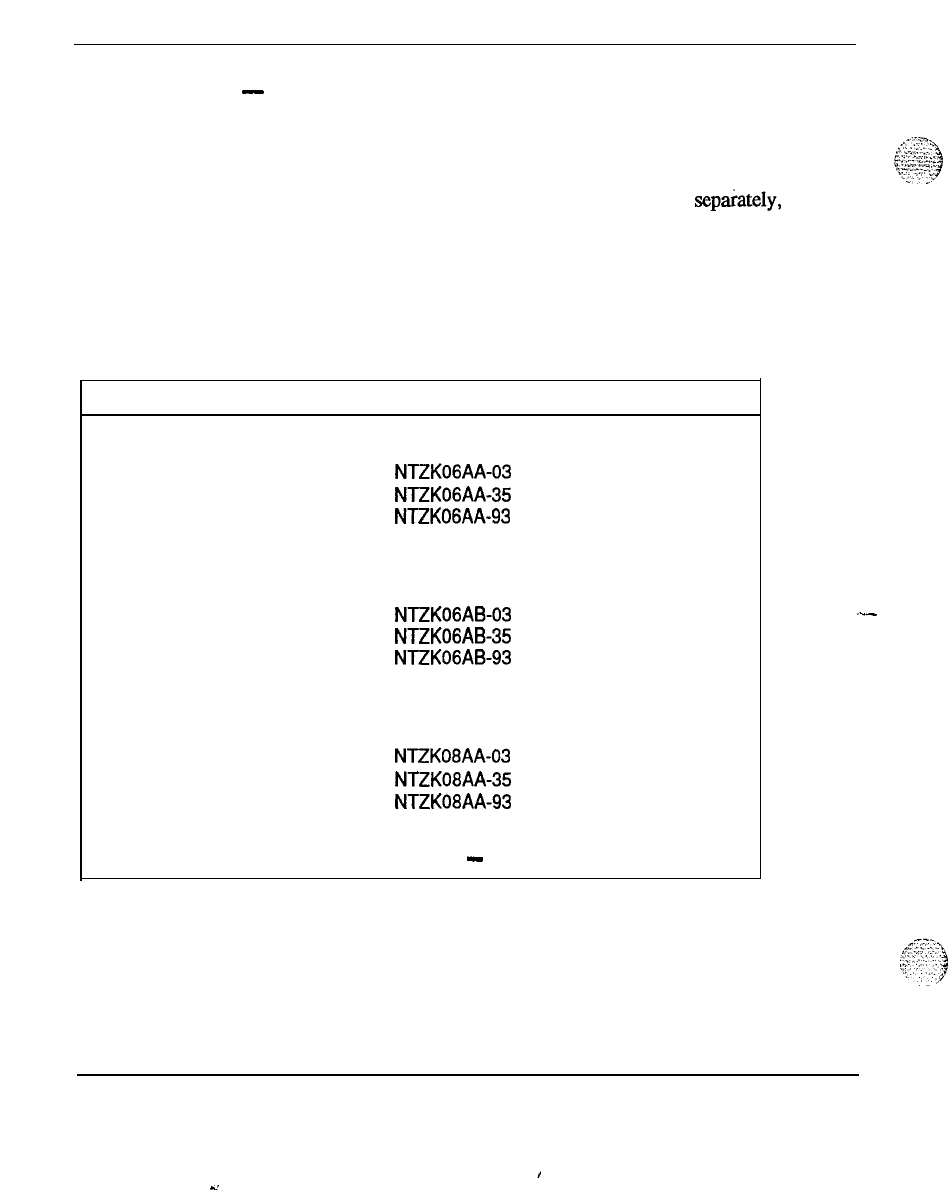
52 Station equipment
-
Key Expansion Module
Table 1 lists the ordering codes for the Meridian Modular Telephones, alone
and with hardware options installed.
Table 2 lists the hardware options that can be purchased separately, and
Table 3 lists miscellaneous items.
Refer to
Meridian Modular Telephones-Description and specifications
(553-2201-116) for additional information.
Table
1
Order
codes
for Meridian Modular Telephones and factory installed options
Description Ordering code
M2006 (Basic)
Black
Chameleon Ash
Dolphin Gray
M2006 (with MPDA)
NTZKOGAA-03
NTZK06AA-35
NTZK06AA-93
Black
Chameleon Ash
Dolphin Gray
M2008 (Basic)
Black
Chameleon Ash
Dolphin Gray
NTZKOGAB-03 (with power board)
NTZK06AB-35 (with power board)
NTZK06AB-93 (with power board)
NTZK08AA-03
NTZK08AA-35
NTZK08AA-93
-continued
-
Equipment identification and ordering information 553-3001-154
,
-’
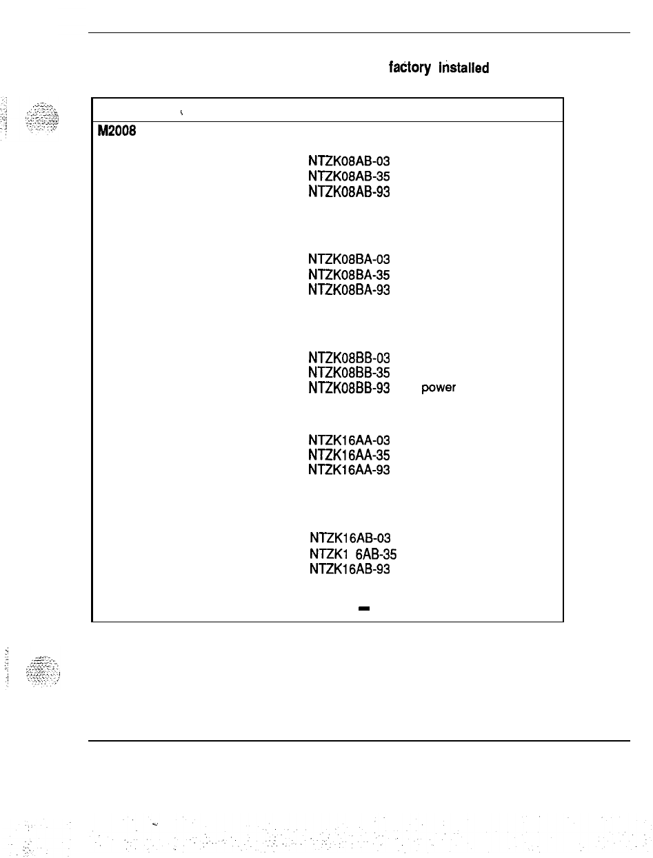
Station equipment 53
Table 1
Order codes for Meridian Modular Telephones and faCtory histalled options
(continued)
Description
i
Ordering code
M2008 (with MPDA)
Black
Chameleon Ash
Dolphin Gray
M2008 (with Display)
NTZK08AB-03 (with power board)
NTZK08AB-35 (with power board)
NTZK08AB-93 (with power board)
Black NTZK08BA-03 (with power board)
Chameleon Ash NTZK08BA-35 (with power board)
Dolphin Gray NTZK08BA-93 (with power board)
M2008 (with MPDA and Display)
Black
Chameleon Ash
Dolphin Gray
M2616 (basic)
NTZK08BB-03 (with power board)
NTZK08BB-35 (with power board)
NTZK08BB-93
(with
power
board)
Black
Chameleon Ash
Dolphin Gray
M2616 (with MPDA)
NTZK16AA-03
NTZKl6AA-35
NTZK16AA-93
Black
Chameleon Ash
Dolphin Gray
NTZK16AB-03 (with power board)
NTZKI
6AB-35 (with power board)
NTZKl6AB-93
(with power board)
-continued
-
Equipment identification and ordering information 553-3001-l 54
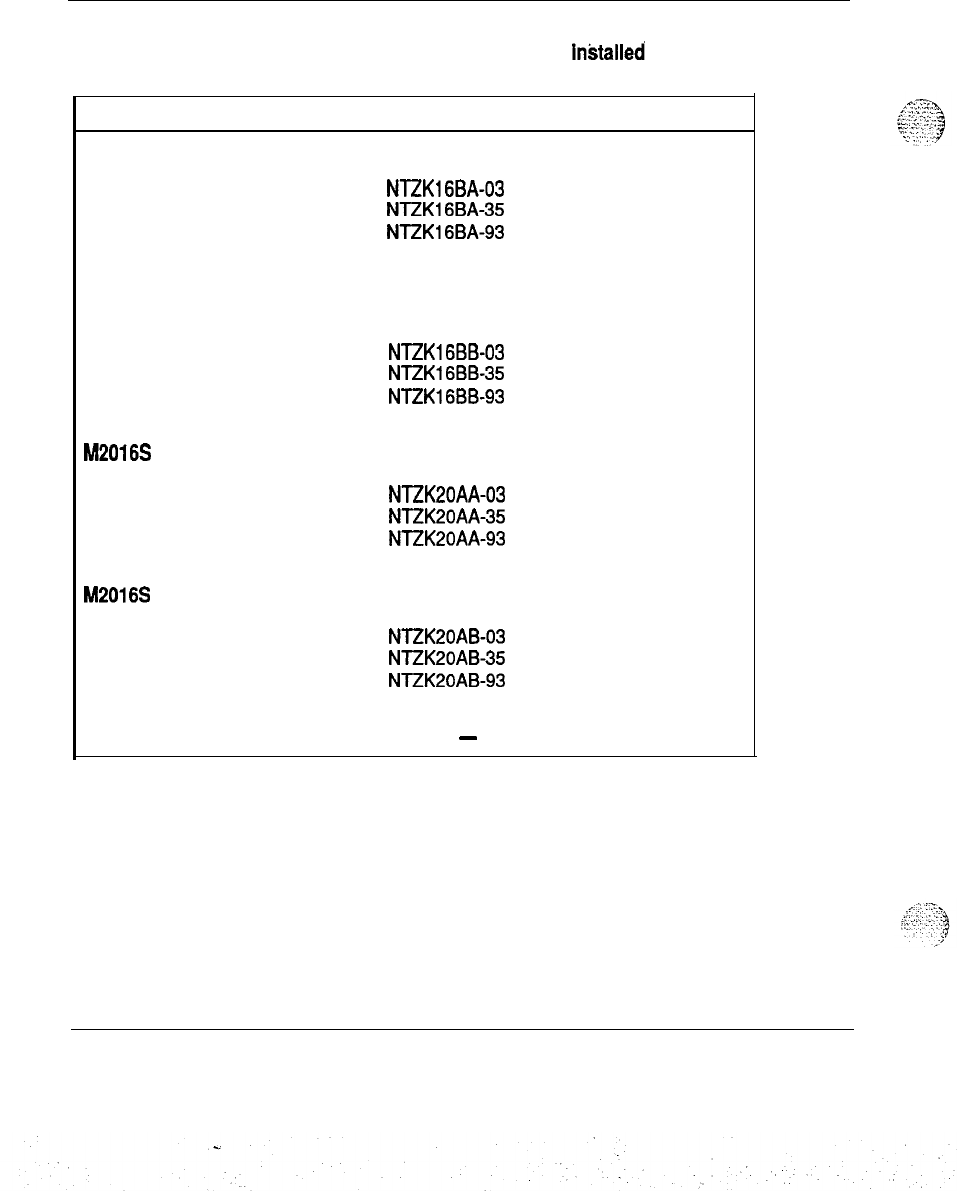
54 Station equipment
Table
1
Order codes for Meridian Modular Telephones and factory inktalled options
(continued)
Description Ordering code
M2616 (with Display)
Black
NTZKl6BA-03
Chameleon Ash
NTZK16BA35
Dolphin Gray NTZK16BA-93
M2616 (with MPDA and Display)
Black
Chameleon Ash
Dolphin Gray
NTZK16BB-03 (with power board)
NTZK16BB-35 (with power board)
NTZK16BB-93 (with power board)
M2016S (basic)
Black
Chameleon Ash
Dolphin Gray
M2016S (with MPDA)
NTZK20AA-03
(with power board)
NTZK20AA-35
(with power board)
NTZK20AA-93
(with power board)
Black
Chameleon Ash
Dolphin Gray
NTZK20AB-03 (with power board)
NTZK20AB35
(with power board)
NTZK20AB-93 (with power board)
-continued
-
Equipment identification and ordering information 553-3001-154
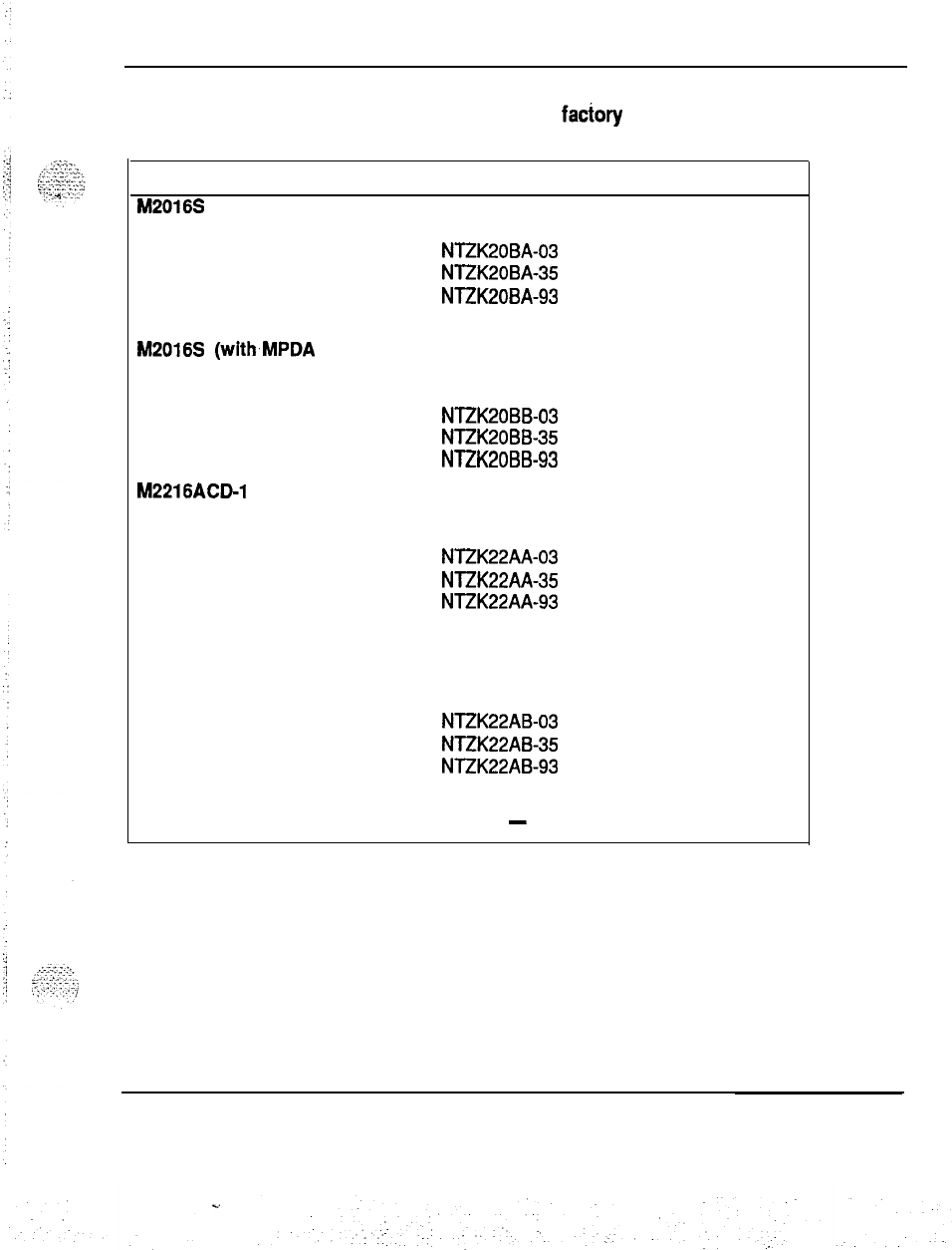
Station equipment 55
Table
1
Order codes for Meridian Modular Telephones and factory installed options
(continued)
Description ,
M2016S (with Display)
Ordering code
Black
NTZK20BA-03 (with power board)
Chameleon Ash NTZK20BA-35 (with power board)
Dolphin Gray NTZK20BA-93 (with power board)
M2016S (withMPDA and Display)
Black
Chameleon Ash
Dolphin Gray
M2216ACP1 (basic-with ACD
Display)
NTZK20BB-03 (with power board)
NTZK20BB-35 (with power board)
NTZK20BB-93 (with power board)
Black
Chameleon Ash
Dolphin Gray
M2216ACP1 (with MPDA and
ACD Display)
NTZK22AA-03
NTZK22AA-35
NTZK22AA-93
Black
Chameleon Ash
Dolphin Gray
NTZK22AB-03 (with power board)
NTZK22AB-35 (with power board)
NTZK22AB-93 (with power board)
-continued
-
Equipment identification and ordering information 553-3001-154
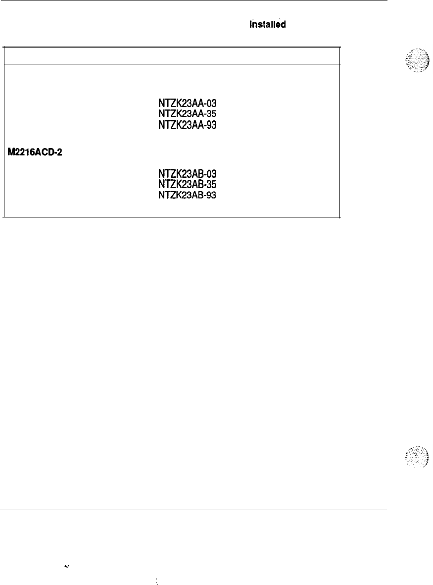
56 Station equipment
Table 1
Order codes for Meridian Modular Telephones and factory
iktalled
options
(continued)
Description Ordering code
M2216ACP2 (basic-with ACD
Display)
Black
Chameleon Ash
Dolphin Gray
M2216ACD-2 (with MPDA)
NTZK23AA-03
(with power board)
NTZK23AA-35
(with power board)
NTZK23AA-93
(with power board)
Black NTZK23AB-03 (with power board)
Chameleon Ash
NTZK23AB35
(with power board)
Dolphin Gray NTZK23AB-93 (with power board)
Equipment identification and ordering information 553-3001-154
C.
:.
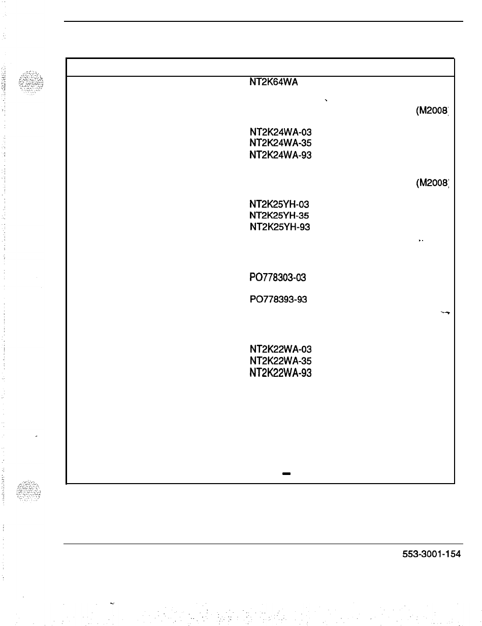
Station equipment 57
Table 2
Ordering codes for optional hardware
Description Ordering code Additional requirements
Meridian Progfammabie Data Adapter
NT2K64WA Power Supply Board
Display Module
-
Power Supply Board
(M2008:
Black NT2K24WA-03
Chameleon Ash
NT2K24WA35
Dolphin Gray NT2K24WA-93
ACD Display Module
Power Supply Board
(M2008;
Black NT2K25YH-03
Chameleon Ash NT2K25YH-35
Dolphin Gray NT2K25YH-93 I.
Top cover filler plate
Black
Chameleon Ash
Dolphin Gray
22 Key Expansion Module
Black
Chameleon Ash
Dolphin Gray
Single Key Module Footstand
PO778303-03
PO77833535
PO778393-93
.-
Power Supply Board
NT2K22WA-03
NT2K22WA-35
NT2K22WA-93
Black
Chameleon Ash
Dolphin Gray
PO7801 03-03
PO7801 35-35
PO7801 93-93
-continued
-
Equipment identification and ordering information 553-3001-154
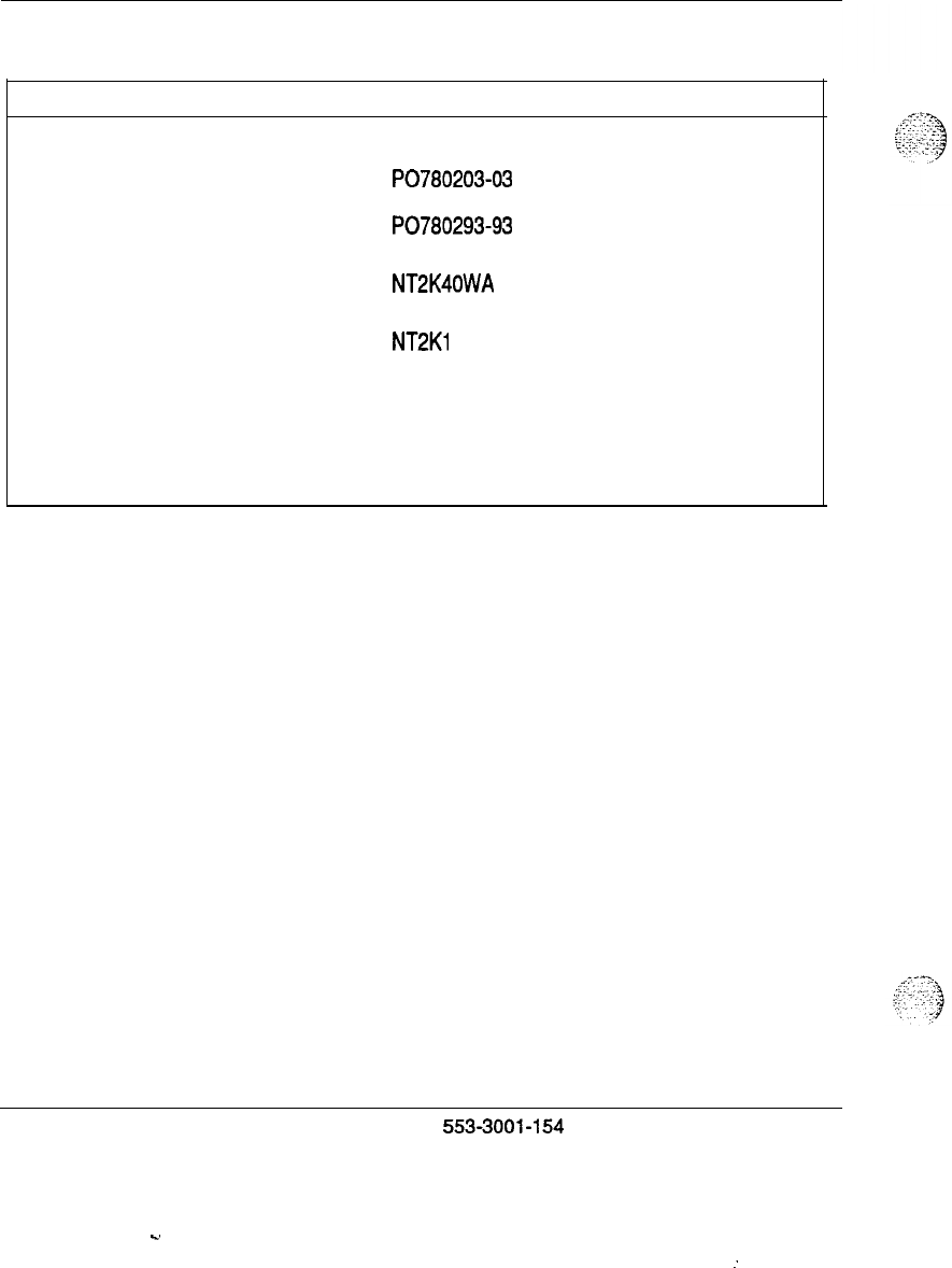
58 Station equipment
Table 2
Ordering codes for optional hardware (continued)
Description Ordering code Additional requirements
Double Key Module Footstand
Black
PO780203-03
Chameleon Ash PO78023535
Dolphin Gray PO780293-93
External Alerter Interface NT2K40WA Power Supply Board
Power Supply Board NT2Kl OWA Transformer or closet power
120 V Transformer A0367335 Power Supply Board
240 V Transformer A036791 4 Power Supply Board
Equipment identification and ordering information
5533001-154
C.
:
Station equipment 59
:
-..
Table 3
Ordering codes for miscellaneous items
Description
Card, Directory Number
Black
Chameleon Ash
Dolphin Gray
Card, key labels
Lens, Directory Number
Handset
Ordering code
PO665352
PO665352
PO652746
PO657709
PO652720
Black
Chameleon Ash
Dolphin Gray
Handset cord, 2.7m. (9 ft)
Black
Chameleon Ash
Dolphin Gray
Handset cord, 3.6 m. (12 ft)
Black
Chameleon Ash
Dolphin Gray
Line cord
-continued
-
A0338908
A0329 173
A03291 74
A0334590
A031
8327
A031 8330
A0274233
A0274243
A031 4423
A0346862
Equipment identification and ordering information 553-3001-154
60 Station equipment
Table 3
Ordering codes for miscellaneous items (continued)
Ordering code
Set User Guide (regular)
Set Reference Card
Display Module Reference Card
Display Installation Sheet
Meridian Programmable Data
Adapter User Guide
PO703991
PO704094
-
PO704096
PO706836
PO705986
M2216ACD User Guide PO704747
ACD Reference Card PO705952
M2000 series digital telephones
The following types of M2000 digital telephones are available for integrated
voice and
data communications:
-
The M2009 (NTlFOS) has 9 keys for features and lines
-
The M2018 (NTlFO7) has 18 keys for features and lines
-
The M2112 (NTlFO7) has 12 keys which are as follows:
.
11 keys for features and lines
.
one key
to
control the built-in handsf&e feature
-
The M2317 has 17 keys which are as follows:
.
11 programmable keys
.
one key to control the built-in handsfme feature
.
five soft keys which are programmable for software features
Equipment identification and ordering information 553-3001-l 54
. .
:,
:.
Station equipment 61
An asynchronous data option circuit board (NTlFO9) and data option power
supply (NFS50220-04Ll) are available for the M2000 series digital
telephones to provide for connecting data terminals to the sets.
For additional information on these telephones, refer to M2000
Digital
Telephones
-
Description, Installation, Operation, and Maintenance
(553-2201-110).
M3000Touchphone
The M3000
(NTlFl
1) Touchphone is a digital integrated voice and data
telephone with a touch sensitive Liquid Crystal Display (LCD) screen for
feature implementation. Refer to
Meridian A43000 Touchphone
-
Description, installation, operation, and maintenance
(553-2201-115) for
additional information.
An asynchronous data option circuit board
(NTlFlO)
and data option power
supply (TEC 00020) are available to provide for connecting data terminals
.
to the sets.
NE-500/2500 telephone set
These are standard single line 500-type rotary dial sets and 2500-type
Digitone
pushbutton dial sets that may be used with the Meridian 1 system.
Standard 48-V talk battery and 20-Hz ringing voltage are available so that
conventional equipment such as telephone answering, dictation, data sets,
modems, key telephones, can be used with the Meridian 1 system.
If the message waiting lamp feature is required, use NE-SOOYR,
.
NE-2500YQA sets.
Ml250 and 2250 attendant consoles
;
:
:
-:-
:;-
:
_‘.
_:
:‘-
:;:
: :
The Ml250 and M2250 incorporate design improvements based on the
Attendant Console QCW4E and are functionally compatible with the
QCW4. The Ml250 is driven and powered by analog line cards and is
compatible with QCW4 console cabling schemes. The M2250 is driven and
powered by a digital line card and has a modified cabling scheme. The
following list describes the applications for SL-1 System attendant consoles.
-
The Ml250 is designed to work in analog mode and functions through
an analog line card when connected to a digital switch.
Equipment identification and ordering information 553-3001-154
62 Station equipment
-
The M2250 is a digital version of the.Ml250, offering additional
features. A digital link
connects the
M2250 to the switch.
Refer to MI250 and M22.50 Attendant ConsoIes
description
(553-2201-117)
for additional information.
Attendant administration overlay template
This plastic overlay is placed over the attendant console to indicate the key
functions when using the Attendant Administration feature. Order number
is PO613887. Refer
to
Xl1
features and services
(553-3001-305) for more
details.
QMTI and QMT2 key/lamp expansion modules
These modules allow the expansion of key/lamp field of QSU-type
telephone sets or QCW-type attendant consoles for additional directory
number and feature activation facilities. These modules require a local.24 V
plug-in transformer or a
QUTl
centralized power unit.
-
QMTl
-
consists of one Xl-button nonlocking key strip
-
QMT2
-
consists of two lo-button nonlocking key strips.
QMT3 lamp field array module
.-
This is an add-on module for QSU-type telephone sets or QCW-type
attendant consoles to display the busy-idle status of 150 consecutive
stations. It requires a local 15 V plug-in transformer or a
QUTl
centralized
power unit. Refer to
QSU-Telephone Sets, Add-On Modules, interface kits
and Meridian Ml000 Series Telephones description
(553-2001-l 10) for
more information.
QMT4 handset module
This module is used as a handset cradle to hold the attendant console
handset. No active components are contained inside the module.
This module includes the NE-G3 handset. It may be attached to the console
or left freestanding. It contains two jacks to accommodate a standard
headset or handset plug when module is attached to the console. It also
allows hearing aids to be coupled with telephone adaptors to the handsets.
Refer to
Attendant Consoles and Add-On Modules-Description (553-
2001-l 15) for more information.
Equipment identification and ordering information 553-3001-154
Station equipment 63
If QCW4E or later vintage is used, either a.QMT4C must be used or the
QMT4A or QMT4B must be used as standalone cradles.
QMTI 1 asynchronous/ synchronous interface module
The Asynchronous/Synchronous Interface Module (AS&I) is similar to the
QMT9 but provides added dialing capabilities and six data feature keys and
associated lamps and data control switches. Refer
to SL-1 Data Feature
-
General description andprovisioning
(553-2731-100) for more information.
QMT12 add-on data module
The synchronous
ADM
provides a
CCIlT
V.35 interface between the
Meridian 1 system and customer-supplied dam equipment. Refer to SL-I
Data Feature-General description and provisionin
(553-2731-100)
for
more information.
Each ADM requires a local supplementary power supply such as the
PO593922 or PO610756 transformer.
I.
QMTI 5 amplified handset module
This module is similar to the QMT4 module, with addition of an amplifier
for the hearing impaired. It includes a volume control, 2 headset plugs on
the right side of the module which plug into the headset jacks on the
__
console. It also has 2 headset/handset plugs on the left side. One (attendant
jack) is under control of the amplifier; the second (supervisor jack) cannot
have its volume adjusted.
QMT21 high-speed
data
module
This module is similar to the
QMTll
module. It provides RS-232/V.35
interface and allows synchronous data transmission of up to 64 kbps. It
provides connectivity to the Data Terminal Equipment (DTE) for intra-
switch communications, as well as wide area communications over DTI/PRI
links to other Northern Telecom switches. Refer
to
QMZZ High-Speed
Data Module -Description, installation, and operation
(553-2731-107)
for more information.
QUSI logic handsfree unit
This unit provides handsfree voice switching facilities on the SL-1
telephone. Refer to 512-6251-200 for a complete description.
Equipment identification and ordering information 553-3001-154
64 Station equipment
QKKI
handsfree remote powering kit
This kit is used to modify SL- 1 telephone sets for use with the QUS 1 Logic
handsfiee unit and to extend the SL-1 set operating range from 1830 m
(6000 ft) to 2438 m (8000 ft). It requires a 24 V ac local transformer
(ordered separately).
This kit is field-installable inside a set. Refer to
QSU-Telephone Sets, Add-
On Modules, interface kits and Meridian Ml000 Series Telephones
description
(553-2001-l 10) for more information.
QKK3 automatic handsfree interface kit
This kit is the same as
QKKl
for systems with the Automatic Answer
feature. It automatically answers calls after a single ring (see QKK8 and
refer
to
QSU-Telephone Sets, Add-On Modules, interface kits and Meridian
Ml000 Series Telephones description
(553-2001-l 10)).
QKK8 automatic handsfree interface kit
This kit is the same as QKK3 but for QSU71 sets only.
QKM13 light probe kit
This kit enables a sight-impaired person to use existing consoles and SL-1
sets. The probe consists of a small hand-held box with a light sensor.
--
When the sensor is placed over an LED that is on, a tone is heard in the
handset or headset, Refer to
Attendant Consoles and Add-On Modules
description
(553-2001-l 15) for more information. Two PO590352
connector kits are required to install the light probe into an SL-1 set.
QKNI headset kit
This kit is used to modify QSU-type telephone set for
NE-5Ztype
Venture
1 or equivalent headset operation. Refer
to
QSU-Telephone Sets, Add-On
Modules, interface kits and Meridian Ml 000 Series Telephones description
(553-2001-l 10) for more information.
This kit provides the following features:
-
field-installable inside a set
-
jack and ON-OFF switch are located in the filler plate position on the
left-hand side of the set
,..-
7.
..”
‘7
;;
,.
. .
.:
:..
:.:‘,
:
1
‘,’
Equipment identification and ordering information 553-3001-154
Station equipment 65
-
no supplementary power is required
::
QSR2 venture 1 headset
.>;
.::
‘L..
.
..~
_.,
4
_
_
_
.
.-.,
._.
.._
:I:--”
This set is used in conjunction with the
QKNl
headset kit to provide head
._
. .
telephone set operation. Refer to
QSU-Telephone Sets, Add-On Modules,
interface kits and Meridian Ml 000 Series Telephones description
(553-2001-110) for more information.
This headset provides the following features:
-
lightweight (17 g)
-
ear-mounted
-
left or right
-
six different sizes of eartips
-
acoustic, noise-canceling transmitter held close to user’s mouth by a
thin, plastic covered, stainless steel arm attached to the headset capsule
I.
QSAM2A and QSAM3A group listening switch kit
This kit allows the speech of both parties to be heard through the speaker of
the SL-1 set. Refer to
QSU-Telephone Sets, Add-On Modules, interface kits
and Meridian Ml000 Series Telephones description
(553-2001-l 10) for
more information.
.-
An ON/OFF switch is mounted in the left-hand filler plate of a QSU-type
set. When ON, the speech of the SL-1 set user and the connected party are
heard through the speaker of the SL-1 set. When OFF, the SL-1 set
functions normally.
-
QSAM2A
used on phase I SL-1 sets
-
QSAM3A
used on phase II SL-1 sets,
(QSUlF
and later vintage)
Asynchronous data options
These microprocessor-controlled devices provide the interface (RS-232
compatible) through which ASCII Data Terminal Equipment (DTE) may be
connected to the Meridian 1 network. Two types of asynchronous data
---- --
:.:.
-;
._
options are available for use with the following digital telephones:
-
NTlFOBAA printed circuit board for use with M2009, M2018 and
M2112 digital telephones. Refer to
Meridian M2000 Digital
Equipment identification and ordering information 553-3001-154
66 Station equipment
Telephones -Description, installation, operation, and maintenance
(553-2201-l 10) for more information.
-
NTlFlOAA
printed circuit board assembly and housing for M3000
,-,.
.c;
_
.‘..F
digital touchphone. Refer to
Meridian h43000 Touchphone
-
1.
. __
“;.‘“.‘-,.:
,
Description, installation, operation, and ma@tenance
(553-2201-l 15)
for additional information.
The following features are available:
-
Automatic data rate detection at all rates using the ASCII “Carriage
Return” character
-
Keyboard dialing for originating data calls to local and remote hosts or
DTE from the terminal keyboard
-
Break detection and generation
Meridian programmable data adapter
.
This adapter provides the interface (RS-232 compatible) through which
ASCII Data Terminal Equipment (DTE) may be connected to the Meridian
1 network. It is available with the M2006, M2008, M2016S, and M2616
Meridian Modular Telephones
Some of the features available are as follows:
.-
-
keyboard dialing for originating data calls to local or remote hosts or
DTE
-
telephone keypad dialing for originating and releasing data calls
-
-
parameter setting from telephone keypad
-
voice call origination from terminal keyboard
-
script file capabilities to pre-program resource locations via mnemonic
address names
Teledaptm
Teledapt standardized telephone connectorization for QSU-type sets
provides an alternative to the conventional spade tip form of set termination.
QSU-type sets possessing the Teledapt capability are designated by “ QM”
suffix on the set code (i.e., the
QSUlEQM).
while “QM” sets use a 2 m
(7
ft)
cord, the
NED6QF
Teledapt cord assembly may be ordered
Equipment identification and ordering information 553-3001-154
Station equipment 67
separately in 2 m (7 ft), 4 m (14 ft), qr 7.5
m
(25 ft) lengths for conversion
of existing SL-1 sets. These assemblies are compatible only with the
Teledapt jacks designed for the system.
. .
.,
.-,’
l,
. .
:.;
.;
”
s”Tz$
‘C\
”
,’
Station
equipment
replaceable
items
Table 4 lists the individual parts of the station equipment that are field-
replaceable. These parts may be ordered by using the given apparatus
number.
.
.
.
. .
.
_:
:y:
^
/:
‘.
.I
.
.
. .
.
.
.
,..:
.:
j
I-.
,:
::::
.
.;
Equipment identification and ordering information 553-3001-154
.
.
68 Station equipment
Table 4
Station equipment replaceable items
Equipment
GICW-Type Attendant Consoles
3CWl
, QCW2 only
QCW3, QCW4 only (see Note)
M2006, M2008, M2016S, M2216,
and M2616 sets
Replaceable items Apparatus
number
Cover Assembly PO538435
Attendant Administration
-
c
Overlay
PO61 3887
Console Caps Package PO58631 2
Bezel PO567037
Bezel PO578254
Dial Pad PO536503
LED Assembly (1 strip)
PO548801
LED Assembly (2 strips)
PO548799
LED Assembly (3 strips) PO548800
Line Cord N E-D50QE-35
8-Digit Display (QCW2) PO578270
Key button strip PCB QPC246
(QCW3 only)
Key button strip PCB
QPC247
Key button strip PCB QPC248
Directory Number Card P0665352,
PO652740
Key Label Card PO657709
Directory Number Lens PO652720
Handset
Black
A0338908
Chameleon Ash A03291 73
Dolphin Gray A0329 174
Handset Cord (2.7 m/g ft)
Black
A0334590
-continued
-
Equipment identification and ordering information 553-3001-154
%.
:
:

Table 4
Station equipment replaceable items (continued)
Station equipment 69
Equipment
All Sets and Consoles
Replaceable items
Chameleon Ash
Dolphin Gray
Handset Cord (3.6 m/l 2 ft)
Black
Chameleon Ash
Dolphin Gray
Line Cord
Card Holder
Filler Plate
Apparatus
number
AQ318327
A031 8330
A0274233
A0274243
A031 4423
A0346862
PO535652
PO523535
I
Note: The QCW3 houses one QPC246, one QPC247 and one QPC248. The
QCW4
houses one
QPC247 and two QPC248
PCBs
(right and left).
Equipment identification and ordering information 553-3001-154

70 Station equipment
Equipment identification and ordering information 553-3001-154
.w
,:
:
71
Cabling
The cables are differentiated by the cabling method used. Two types of
cables are available.
Intra-UEM cables are cables that connect to different cards within a UEM,
or cables that go to the I/O connector panels at the rear of the UEM.
Intra-UEM cables are not shielded. These cables arc typically round and
use bail locks or screws to prevent accidental removal.
Inter-UEM cables are cables that are routed internally between UEMs.
These cables are used primarily for interconnecting the following
subsystems together:
-
CPU
toCPU
.-
-
CPU to Network
-
Network to Network
-
Network to Peripheral Equipment
All of the faceplate connectors use a go-degree cable egress and all of the
backplane connectors use a 180-degree cable egress.
NT7Dl
IAE
module-to-module power harness
Purpose-This power wiring harness is used in DC modules to connect the
input DC power and speed control signals vertically through the column. It
is constructed in a modular form, and can be disconnected when necessary
to allow for the removal and/or replacement of modules. The DC power
harness is larger than that of the AC system since it requires the use of more
input wires in order to handle the lower voltage and its associated higher
current.
Equipment identification and ordering information 553-3001-154
72 Cabling
NT8D40AA AC power cord
Purpose-This cable conducts AC power into the pedestal for AC systems.
It is 9.1 m (30 ft) long.
NT8D40AM
module-to-module power harness
Purpose--This power wiring harness is used in AC modules to connect the
input AC power and speed control signals vertically through the column. It
is constructed in a modular form, and can be disconnected when necessary
to allow for the removal and/or replacement of modules.
NT8D40AY AC power cord
Purpose-This cable conducts AC power into the pedestal for System
options 21A. It is 2.7 m (9 ft) long.
NT8D40BJ
System Monitor to backplane cable
Purpose--This cable is used for System option 21A. It connects the
‘-
System Monitor to the common/peripheral equipment backplane to allow
control and monitoring of the system.
NT8D40BK
System Monitor trip cable
Purpose-This internal cable is used for System option 21A. It connects
.-
the System Monitor to the power distribution unit. It allows the System
Monitor to trip the circuit breaker.
NT8D46AA
System Monitor column cable
Purpose!-This cable is used to connect the monitoring signals vertically
through the column. It is constructed in a modular form, and can be
disconnected when necessary to allow for the removal and/or replacement
of modules.
NT8D46AC
Thermostat harness
Purpose-The thermostat harness is part of the Temperature Sensor
Assembly. It contains two thermal sensors and a fault LED. At 70degree
Celsius, the thermal sensors trip and cause system shutdown. The
thermostat harness plugs into the backplane of the top module.
Equipment identification and ordering information 553-3001-154
C’
Cabling 73
NT8D46AD System Monitbr SDI cable
PurpoeThis
cable is used to connect
an
SD1 card to the System
Monitor.
‘/ i-.:.2-,
It replaces the NT8D46AA System Monitor column cable when the
SD1
is
:j
1
!..,.:
‘c;::!>
. . .
...--..“.-.,i.i
in the same UEM.
-
:
:I
NT8D46AG System Monitor to SDI paddle
boar’d
cable
Purpose-This cable
is used to connect the System Monitor to the
NT8D41AA SD1 paddle board (dual port). It replaces the NT8D46AA
System Monitor column cable when the NT8D41AA SD1 paddle board
(dual port) is in the same UEM.
NT8D46AH System Monitor to MDF cable
Purpose-This cable
is used to connect the System Monitor Power Fail
Transfer Unit to the MDF.
This cable is 9.7 m (32 ft) long.
I.
NT8D46AJ System Monitor to UPS (Best) cable
Purpose-This
cable is used to connect the System Monitor to the Best
Uninterruptable Power Supply (UPS). It is used for UPS monitoring.
This cable is 13.7 m (45 ft) long.
.-
NT8D46AL System Monitor Serial Link cable
Purpose-This cable
is used to connect the System Monitor from one
column to another.
This cable is 2.1 m (7 ft) long.
NT8D46AM Air Probe harness AC
Purpose-The
Air Probe harness AC is part of the Temperature Sensor
Assembly and is used in AC systems. It uses a 24-pin connector. It senses
exit air temperature and relates the information to the blower unit.
Equipment identification and ordering information 553-3001-154
-.
:
.:
.:.
:
74 Cabling
NT8D46AP Extended System’ Monitor Serial Link cable
Purpose-This cable is used to connect the System Monitor from one
column to another.
This cable is 7.6 m (25 ft) long.
NT8D46AQ System Monitor to UPS (Exide) cable
PurposeThis
cable is
used to connect the System Monitor to the Exide
UPS. It is used for UPS monitoring.
This cable is 13.7 m (45 ft) long.
NT8D46AS System Monitor inter-CPU cable
Purpose--This cable is used to connect
the dual CPUs in Meridian 1
System option 71 together for System Monitor monitoring. It replaces the
NT8D46AA System Monitor column cable in both CPU modules.
NT8D46AT System Monitor to QBLIS cable
Purpose-This cable
connects the System Monitor to the
QBLl5
power/battery distribution box. It is used to monitor the DC power plant.
This cable is 9.7 m (32 ft) long.
.-
NT8D46AU System Monitor to UPS (Alpha) cable
Purpose-This
cable is used to connect the System Monitor to the Alpha
UPS. It is used for UPS monitoring.
This cable is 13.7 m (45 ft) long.
NT8D46AV System Monitor to QCA13 cable
Purpos-This
cable
connects the System Monitor to the QCA13 DC
power plant. It is used to monitor the DC power plant.
This cable is 9.7 m (32 ft) long.
Equipment identification and ordering information 553-3001-154
Cabling 75
NT8D46AW System Monitor to QBL12 cable
Purpose----This cable connects the System Monitor to the QBL12 battery
distribution box. It is used to monitor the DC power plant.
This cable is 9.7 m (32 ft) long.
NT8D46DC Air Probe harness DC
Purpose-The Air Probe harness DC is part of the Temperature Sensor
Assembly and is used in DC systems. It uses a 36-pin connector. It senses
exit air temperature and relates the information to the blower unit.
NT8D73 Inter-cabinet Network cable
Purpose--This cable is used to interconnect QPC414 Network cards:
-
from Network Module to PE Module via the I/O connector panels
-
from QCA55 cabinet to PE Module
This cable is available in the following lengths:
-
NT8D73AD 1.8 m (6 ft)
-
NTSD73AF 3.6 m (12 ft)
-
NT8D73AL 6 m (20 ft)
-
NT8D73AS 9.1 m (30 ft)
NT8D74 Clock Controller to Inter Group cable
Purpose-This cable is used to connect the QPC47 1 Clock Controller card
to the NT8D36AA Inter Group Module.
This cable is available in the following lengths:
-
NT8D74AC
1.2m(4ft)
-
NT8D74AD 1.8 m (6 ft)
-
NT8D74AE 2.4 m (8 ft)
-
NT8D74AF 3 m (10 ft)
-
NT8D74A.I
4.8 m (16 ft)
Equipment identification and ordering information 553-3001-l 54
76 Cabling
NT8D75 Clock Controller to Clock Controller cable
Purpose-This
cable is used to interconnect QF’C471 Clock Controller
cards.
This cable is available in the following lengths:
-
NT8D75AC 1.2 m (4 ft)
-
NT8D75AD 1.8 m (6 ft)
NT8D76 Intergroup Switch to Inter Group cable
Purpose-This
cable is used to connect the QF’C412 Intergroup Switch
card to the NT8D36AA Inter Group Module.
This cable is available in the following lengths:
-
NT8D76AC 1.2 m (4 ft)
-
NT8D76AD 1.8 m (6 ft)
-
NT8D76AE 2.4 m (8 ft)
-
NT8D76AF 3 m
(lqft)
-
NT8D76AG 3.6 m (12 ft)
-
NT8D76A.l
4.8 m (16 ft)
-
NT8D76AL 6 m (20 ft)
-
NT8D76AP 7.6 m (25 ft)
NT8D77 FDI to FDU cable
Purpose!-This cable is
used to connect the QPC742 FDI card to the
NT8D68AA FDU card.
This cable is available in the following lengths:
-
NT8D77AES 0.6 m (2 ft)
-
NT8D77AA 0.9 m (3 ft)
-
NT8D77AC 1.2 m (4 ft)
-
NT8D77AD 1.8 m (6 ft)
Equipment identification and ordering information 553-3001-154
.-
:
-.
..:
..:.
..’
__i
.I
.
.
:
.
.
.
.:
.:
1
;::.>
Y,’
:_:.:I
‘: ,...-.
_.
,.
..,
I
tI_
..-.
.
..I
:
-’
‘.
;
--;
_I]
i
._
.I
.:
,:.
..i
:
1..
:I
,..;
r
:-..
...
Cabling 77
NT8D78AA
CPU cable
-
Purpose-This cable is used to connect the QPC580 CPU Interface card to
QPC579 CPU Function card.
This cable is 5 cm (2 in.) long.
NT8D79
PRVDTI
to Clock Controller cable
Purpose--This cable is used to connect the PRI/DTI card to the QPC471
Clock Controller card.
This cable is available in the following lengths:
-
NT8D79AB 0.6 m (2 ft)
-
NT8D79AC 1.2 m (4 ft)
-
NT8D79AD 1.8 m (6 ft)
-
NT8D79AE 2.4 m (8 ft)
-
NT8D79AF 3 m (10 ft)
NT8D80 CPU interface cable
Purpose-This cable is used to connect the following:
-
QPC581 CMA card to QPC581 CMA card in a dual CPU
config&ion
-
QPC584 MS1 card to NT8D69AA MDU
-
QPC215 Segmented Bus Extender in CPU to Network via QPC441
3PE
-
QPC4413PE
in Network 0 to
QPC4413PE
in Network 1 (Meridian 1
System option 61 only)
This cable is available in the following lengths:
-
NT8D8OAB 0.6 m (2 ft)
-
NT8D80AC 1.2 m (4 ft)
-
NT8D80AZ 1.5 m (5 ft)
-
NT8D80AD 1.8 m (6 ft)
-
NT8D80AE 2.4 m (8 ft)
Equipment identification and ordering information 553-3001-154
78 Cabling
-
NT8D80AF
3m(lOft)
-
NT8DSOAG 3.6 m (12 ft)
-
NT8D80A.I 4.8 m (16 ft)
-
NT8D80AL 6 m (20 ft)
-
NTSDSOAP 7.6 m (25 ft)
NT8D81AA Tip and Ring cable
Purpose-This cable is used to connect a line card to the I/O connector
panel.
This cable is 50 cm (20 in.) long.
NT8D82 SDI to
I/O
cable
Purpose-This cable is used to connect the the following cards to the I/O
connector panel:
-
QPC757
D-Channel Handler Interface
-
QPC513 Enhanced Serial Data Interface
-
QPC84 1 Four-Port Serial Data Interface
-
QPC687 CPU with SDI/ RTC
This cable is available in the following lengths:
-
NT8D82AC 1.2 m (4 ft)
-
NT8D82AD 1.8 m (6 ft)
NT8D83
PRVDTI
to
l/O
cable
Purpose-This cable is used to connect the PRI/DTI card
(Tl
port) to the
I/O connector panel.
This cable is available in the following lengths:
-
NT8D83AC 1.2 m (4 ft)
-
NT8D83AD 1.8 m (6 ft)
Equipment identification and ordering information 553-3001-l 54
u
.:
_:
Cabling 79
NT8D84AA SDI paddle board (dual. port) to
I/O
cable
Purpose-This cable is used to connect the NT8D41AA SD1 paddle board
(dual port) to the I/O connector panel.
This cable is 45.7 cm (18 in.) long.
NT8D85 Network to PE cable
Purpose-This cable is used to connect the following:
-
QPC58 1 CMA card to QPC58 1 CMA card in dual CPU configuration
-
QPC414 Network card to PRI/DTI card
-
QPC414 Network card to QPC659 Dual Loop Peripheral Buffer card
(for internal cabling only)
-
QPC659 Dual Loop Peripheral Buffer card to QPC659 Dual Loop
Peripheral Buffer card when connecting two NTSD13 PE Modules
together
I.
This cable is available in the following lengths:
-
NT8D85AB 0.6 m (2 ft)
-
NT8D85AC 1.2 m (4 ft)
-
NT8D85AZ 1.5 m (5 ft)
-
NT8D85AD 1.8 m (6 ft)
-
NT8D85AB 2.4 m (8 ft)
-
NT8D85AF 3 m (10 ft)
-
NT8D85AJ 4.8 m (16 ft)
-
NT8D85AL 6 m (20 ft)
-
NT8D85AP 7.6 m (25 ft)
-
NT8D85AT 10.6 m (35 ft)
-
NT8D85AV 13.7 m (45 ft)
-
Equipment identification and ordering information 553-3001-154
80 Cabling
NT8D86 Network to
I/O
cable-
Purpose!-This cable is used to connect the following to the I/O connector
panel:
-
QPC414 Network card
-
PRIlDTIcard
-
QPC659 Dual Loop Peripheral Buffer card
-
NT8D47RPE
This cable is available in the following lengths:
-
NT8D86AC 1.5 m (5 ft)
-
NT8D86AD
1.8
m (6 ft)
NT8D87 Conference/TDS to music trunk cable
Purpose-This cable is used to connect the NT8D17AA Conference/IDS
card to the music trunk or I/O connector panel.
This cable is available in the following lengths:
-
NT8D87AC 1.2 m (4 ft)
-
NT8D87AD 1.8 m (6 ft)
NT8D88 Network to
I/O
cable
Purpose--This cable connects the NT8DO4AA Superloop Network card to
the I/O connector panel.
This cable is available in the following lengths:
-
NT8D88AC 1.5 m (5 ft)
-
NT8D88AD 1.8 m (6 ft)
NT8D90AF SDI multiple-port cable
-
internal
Purpose-This is a multiple-port extension cable for QPC841 Four-Port
SD1 card. This cable is used to connect from the I/O connector panel to the
NT8D96AB cable.
This cable is 3 m (10 ft) long.
--
,._
.,.,
..I
,2
-..
.:
‘%
.I
:.
Equipment identification and ordering information 553-3001-154
Cabling 81
NT8D91
Network to Controller cable
Purpose-This cable is used for internal cabling to connect NT8DO4
Superloop Network card to NT8DOlAD Controller-2 or NT8DOlAC
Controller-4 card.
This cable is available in the following lengths:
-
NT8D91AC 1.2 m (4 ft)
-
NT8D91AD 1.8 m (6 ft)
-
NT8D91AE 2.4 m (8 ft)
-
NT8D91AF
3 m (loft)
-
NT8D91AG 3.6 m (12 ft)
-
NT8D9lAI
4.8 m (16 ft)
-
NT8D91AP 7.6 m (25 ft)
-
NT8D91AT 10.6 m (35 ft)
-
NT8D91AV 13.7 m (45 ft)
NT8D92AB Controller to
I/O
cable
Purpose-This cable is used to connect the NT8DOl Controller card
tothe
I/O connector panel. This method of cabling is used only when the
Network loop is cabled externally to the DEM.
This cable is 50 cm (20 in.) long.
NT8D93 SDI paddle board (dual port)
I/O
to DTE/DCE cable
Purpose-This cable is used to connect the NT8D41AA SD1 paddle board
(dual port) to the DTE or DCE via the I/O connector panel.
j
.i
.
‘.‘_....:,..:
,_
.‘,
This cable is available in the following lengths:
-
NT8D93A.l
4.8 m (16 ft)’
-
NT8D93AW 14.6 m (48 ft)
NT8D95 SDI
I/O
to DTE/DCE cable
Purpose--This cable is used to connect the following cards to the DTE or
DCE via the I/O connector panel:
Equipment identification and ordering information 553-3001-154
.
.
82 Cabling
-
QPC513 Enhanced
Se&l
Data Interface
-
QPC841 Four-Port Serial Data Interface
-
QPC687 CPU with SDI/ RTC
This cable is available in the following lengths:
-
-
NT8D95A.I 4.8 m (16 ft)
-
NT8D95AT 10.3 m (34 ft)
-
NTSD95AW 14.6 m (48 ft)
97AX
PRllDTl to
MWDF
cable
Purpose-This cable connects the PRI/DTI card to the MDF via the I/O
connector panel.
This cable is 15.2 m (50 ft) long.
Purpose--This
cable is used to interconnect NT8DO4AA Superloop
Network cards:
-
from Network Module to IPE Module via the I/O connector panels _-
-
from QCA55 cabinet to IPE Module
This cable is available in the following lengths:
-
NT8D98AD
-
NT8D98AF
-
NT8D98AL
-
NT8D98AS
-
NT8D98AT (not for QCA55 cabinet application)
1.8 m (6 ft)
3.6 m (12
ft)
6 m (20 ft)
9.1 m (30 ft)
11.5 m (38 ft)
Equipment identification and ordering information 553-3001-154
.
.
Cabling 83
NT8D99 CPU to Network cable
Purpose-This cable is used
to:interconnect
NT8D35
NET Modules in full
group configuration
This cable is available in the following lengths:
-
-
NT8D99AR 0.6 m (2 ft)
-
NT8D99AC 1.2 m (4 ft)
-
NTm99AD
1.8 m (6 ft)
NT9J93AD
PRVDTI
Echo Canceler to
I/O
cable
Purpose-This cable is used to connect the PRI/DTI Echo Canceler port to
the I/O connector panel.
This cable is 1.8 m (6 ft) long.
NT9J94AB RPE to
I/O
cable
Purpose-This cable is used to connect the NT8D47 RPE to the I/O
connector panel.
This cable is 0.6 m (2 ft) long.
NT9J96 Intra-cabinet Network cable
Purpose-This cable is used to connect the QPC414 Network card to the
I/O connector panel within an existing SL-1 cabinet (QCA55).
This cable is available in the following lengths:
-
NT9J96AC 1 m (40 in.)
-
NT9J96AD 1.8 m (70 in.)
-
NT9J96AE 2.2 m (85 in.)
-
Nl9J96AG
3.6 m (12 ft)
-
NT9J96AH 4.3 m (14 ft)
-
NT9J96AJ 4.9 m (16 ft)
Equipment identification and ordering information 553-3001-154
84 Cabling
NT9J97
Intra-column Network cable
Purpose-This cable is used to connect the NT8DO4AA Superloop
Network card to the I/O connector panel in a QCA55 cabinet.
This cable is available in the following lengths:
-
NT9J97AC 1 m (40 in.)
-
NT9J97AD 1.8 m (70 in.)
-
NT9J97AE 2.2 m (85 in.)
-
NT9J97AG 3.6 m (12 ft)
-
NT9J97AH 4.3 m (14 ft)
-
NT9J97AJ 4.9 m (16 ft)
NT9J98
Intra-cabinet Network cable
Purpose-This cable is used to connect the QPC414 Network card to the
I/O connector panel of the QCAlO8 or QCA136 cabinet.
This cable is available in the following lengths:
-
NT9J98AC 1 m (40 in.)
-
NT9J98AD 1.8 m (70 in.)
-
NT9J98AE 2.2 m (85 in.)
.
NT9J99
Intra-cabinet Network cable
Purpose-This cable is used to connect the NT8DO4AA Superloop
Network card to the I/O connector panel of the QCAlO8 or QCA136
cabinet.
This cable is available in the following lengths:
-
NT9J99AC 1 m (40 in.)
-
NT9J99AD 1.8 m (70 in.)
-
Nl9J99AE
2.2 m (85 in.)
Equipment identification and ordering information 553-3001-154
Cabling
85
QCADI 28 connector cable
Purpose-Connects QPC472 DTI Carrier Interface (J5) connector to the
cabinet filter panel. It is a 15-conductor flat ribbon cable with a
U-pin
D-type female connector at one end and a 15-pin D-type male connector at
the other.
QCAD274A AC power cord
Purpose-This cable conducts AC power to the NT6D52AA rectifier. It is
2.7 m (9 ft) long.
Equipment identification and ordering information 553-3001-154
. .
.:
:

06 Cabling
Equipment identification and ordering information 553-3001-154
87
Miscellaneous equipment
Field Wiring Kit
System Hardware-All
Purpose-The
NT6D54AA Field Wiring Kit is used in conjunction with
the System Monitor to
QBLl5
cable. It provides the necessary hardware to
connect four NT6D52AA rectifiers to a System Monitor.
. .
Blank Faceplates
System Hardware-All
Purpose-An
NT7DOSAA blank faceplate is required in a slot reserved for
the Ringing Generator when the Ringing Generator is not in place.
.-
Although not required, other unoccupied slots can be covered by any of the
following blank faceplates, depending on the width of the slot:
-
2.2 cm (0.875 in.)
NT8D3lAA
-
2.5 cm (1 in.)
NT8D31AB
NT8D63AA Overhead Cable Tray Kit
System Hardware-All
Purpose-Holds I/O cables that go from the system to the Main
Distribution Frame (MDF). Provides support for overhead cabling tray.
Mounts to the highest module in each column. Each kit consists of the
following:
-
support brackets
-
front and rear top cap air grills with cut-outs
Equipment identification and ordering information 553-3001-154
68
Miscellaneous equipment
Note:
This kit does not include the cable tray.
Earthquake Bracing Kit
System Hardware-All
Purpose-Provides a means to hold together all modules that are stacked
up in vertical expansion so that in the case of an earthquake, the whole
column will move as a unit. Used only for non-raised floor. Each kit
contains the following:
-
four threaded rods
-
two tie bars
-
miscellaneous hardware (nuts and washers)
Three different Earthquake Bracing Kits are available:
-
two-tier
NT8D64AA
-
three-tier
NTSD64AB
-
four-tier
JYlSD64AC
QRY551
Channel Service Unit
Purpose-When
required under FCC regulations (FCC 03), provides a 24-
.-
channel digital interface between a PRI/DTI and
Tl
line when connecting to
registered common carrier trunks.
TELLABS 251 24-Channel Digital Echo Canceller
Purpose-For use with PRI/DTI when echo control is required on voice
calls.
BIX Cross-Connect System
Purpose-The
BIX In-Building Cross-Connect System provides modular
terminations and cross-connections for Meridian 1 system. (See
63 1-451 l-100 for ordering information for the BIX system and Table 5 for
designation label ordering information.)
Equipment identification and ordering information 553-3001-l 54
s.
:
:
:
I
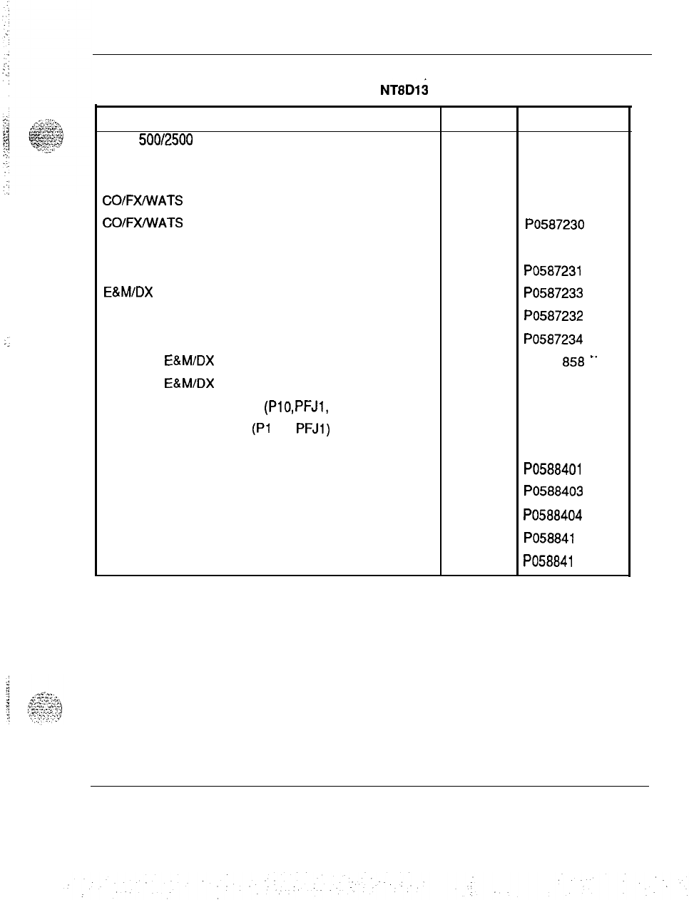
Miscellaneous equipment 89
Table 5
Order Numbers for BIX Designation Labels for
NT8D13
PE Modules
Description Color Order number
Basic 500/2500 set labels (eight circuits per card). A set White PO641 810
of four labels for each PE shelf is used
SL-1 set (eight circuits) Blue PO641 813
COIFXAVATS
trunk (four circuits) Green PO641812
COIFXANATS
trunk (two circuits)
Green PO587230
Loop Signaling trunk (four circuits) Red PO641 811
Loop Signaling trunk (two circuits) Red PO587231
E&M/DX
and Paging trunk (two circuits) Yellow PO587233
Recorded Telephone Dictation trunk (two circuits) Orange PO587232
Recorded Announcement trunk (two circuits) Purple PO587234
Four-Wire
E&M/DX
Type I trunk (two circuits)
Yellow PO631 a58 ..
Four-Wire
E&M/DX
Type II trunk (two circuits)
Yellow PO631 859
Power Fail Transfer cables
(PlO,
PFJl,
PFJ2)
Yellow PO641 814
Power Fail Transfer cables
(Pl
0,
PFJl)
QUA6 Power Fail Yellow PO686506
Transfer Unit
Blank labels for sets Yellow Po5884oi
Blue PO588403
Silver PO588404
Blank labels for trunks and riser cables Green PO58841 5
Blue PO58841 6
Equipment identification and ordering information 553-3001-154
90 Miscellaneous equipment
Northern Telecom Publicatidns
Northern Telecom Publications are packaged in standard Northern Telecom
binders to support the various Meridian 1 systems.
Title and description Qrder number
Installation and maintenance guide
-
System options PO71 0530
21,51,
61, 71
Planning and engineering guide
-
System options 21, PO71 0531
51, 61, 71
X1 1 software guide PO71 0532
Xl 1 input/output guide
PO71 0533
Special features guide PO71 0534
Automatic Call Distribution reference guide PO71 0535
Meridian Link general guide PO71 0536
Equipment identification and ordering information 553-3001-l 54
91
List of terms
ACD
Automatic Call Distribution
ASIM
Asynchronous/Synchronous Interface Module
BPS
Bits Per Second
BTU
Bus Terminating Unit
CAS
Centralized Attendant Service
cc
Clock Controller
CE
Common Equipment
CMA
Changeover Memory Arbitrator
co
Central Office
CPU
Central Processing Unit
Equipment identification and ordering information 553-3001-154
92 List of terms
CRT
DCE
DCHI
DID
DTE
DTl
DTMF
DTR
EIA
FDI
FDU
HSDC
IGS
I/O
Cathode Ray Tube
Data Communication Equipment
D-Channel Handler Interface
Direct Inward Dialing
Data Terminal Equipment
Digital Trunk Interface
Dual Tone Multi Frequency
Digitone
Receiver
Electronics Industry Association
Floppy Disk Interface
Floppy Disk Unit
High-Speed Data Card
Intergroup Switch
Input/Output
Equipment identification and ordering information 5533001-154
List of terms 93
ISDLC
Integrated Services Digital Line card
Integrated Services Digital Network
LRE
Logic Return Equalizer
MCDS
Multi-Channel System
MDF
Main Distribution Frame
MDU Multi-Disk Unit
MSI
Mass Storage Interface
MSU
Mass Storage Unit
OAID
Outgoing Automatic Incoming Dial
b.
.
.
.
,:,:y;.7.-.
,
.
.
,
.
. ;
:
.‘.,.,..”
:
;;
-.:
OANI
Outgoing Automatic Number Identification
OPX
Off-Premises Extension
PAD
Packet Assembler/Disassembler
PBX
Private Branch Exchange
PCM
Pulse Code Modulation
Equipment identification and ordering information 553-3001-154
.
.
‘.
:
.-
-.

94 List of terms
PE
Peripheral Equipment
PRA
Primary Rate Access
PRI
primary Rate Interface
RAM
RAN
Random Access Memory
Recorded Announcement
ROM
Read-Only Memory
RPE
Remote Peripheral Equipment
SBE
Segmented Bus Extender
SCG
System Clock Generator
SDI
Serial Data Interface
TCM
TDS
Time Compression Multiplexing
Tone and Digit Switch
UEM
Universal Equipment Module
Equipment identification and ordering information 553-3001-l 54
^-.
.
_../
.:.j
I
,;
.
.

List of terms 95
UPS
Uninterruptable Power Supply
3-Port Extender
Equipment identification and ordering information 553-3001-154

SL-1
System options 21,51,61,71
Equipment identification and
ordering information
0
1990 Northern Telecom
All rights reserved.
Information subject to change without notice.
Release 1
.O
Standard
January 29, 1990
Printed in U.S.A.
Et
narthorn
t~lacom
.
.
.
.
ti
northtzrn
telecom
PRACTICE
553-2201-180
Issrzid:
88 01 27
Standard
INTEGRATED SERVICES NETWORK
MERIDIAN
l
SERIES
DIGITAL TELEPHONES
LINE ENGINEERING
CONTENTS
Note: The module indicated by a bullet
(@)
in
the
checklist has been
revised. The reason for this revision is given in tbe first page of the
af f acted module.
Prinkd
in U.S.A. ‘Northern
T&corn
Limited
Page i
1 Page

.:-
. .
ITEM
cxoooo
l-P 0010
DP
1001
DP 1002
DP 1003
DP 1004
DP 1005
DP 1006
DP 1007
IX 9999
ISSUE
Standard
Standard
Standard
Standard
Standard
Standard
Standard
Standard
Standard
Standard
CHECKLIST
pzizJFq
DATE
86 06 05
86 06 05
86 01 27
86 01 27
86 01 27
86 01 27
86 01 27
86 01 27
86 01 27
86 01 27

ENGINEER TELEPHONE LINE
pjgFFJq
NOTES
Note: This module is reissued
to
change the minimum loop length requirement to
100
ft.
and to add metric equivalents.
(I) Cable pair selections must meet the following requirements:
l AC signal loss must be
less
than 12.9
dB
at 256
kHz
due to all sources
l
DC loop resistance must be less than 175 Ohm
l Minimum loop length (mainframe bulkhead to telephone) of 30 m (100 ft)
l Near end crosstalk coupling loss
>38dB
at
NyTuist
frequency of 256
kHz
(not an issue for typical 22, 24, and 26 AWG twisted pair cable)
l No bridge taps are permitted
l No loading coils are permitted
e
Protection devices of the carbon-block and gas-filled type are permitted
if the off-state shunting impedance is better than 10
Megohm
resistive,
and less than 0.5.pF capacitive.
(2) The following criteria have to be met where undercarpet cabling is used.
l characteristic impedance at 256
~Hz,
100
f
10 Ohm
l insertion loss at 256
Wz,
<
4.6
dB/kft
l next pair-to-pair coupling loss at 256
kHz,
>
40
dB
(3) For the typical system of 22, 24, or 26 AWG standard twisted pair cable,
the requirements translate to the following allowable loops.
. .
l
up to 915 m (3000 ft) of 22 or 24 AWG cable
l
up to 640 m (2100 ft) of 26 AWG cable
(4) If selected cable pair does not work satisfactorily. select another cable
pair using the following flowchart (Page 2):
-1
ENGINEER TELEPHONE LINE
-[
11
Select (another) loop that
meets the criteria for
cable length.
(DP
1001)
.[21--
.
l Is there a bridge
l
.
UP?
l No
l c31-.
l
Is there another
.
. loop available?
l Yes
l
. .
0
.
.7
Remove the bridge tap.
cl
step 5
Page 3
rl
step 1
I
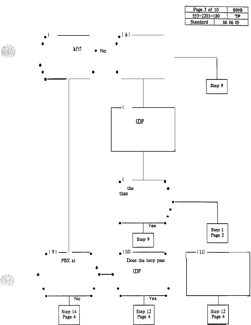
ENGINEER TELEPHONE LINE
.[
51 .
.[61
.
0
Is the loop length l
a
Is there any 26 .
.
less than 2.1 kft?
@No
.AWG cable in the l No
a
l -
loop?
.
.
.
.-
.
Yes l
. .
l -
0
a
.
Yes l
L&l
step 9
.[91-
-[
71
Calculate the loop
resistance (DP 1002)
.[
81
0
l Is
the
resistance less
0
l
than
175 Ohm? . No
a
.
.
l Is the
PBXat
the ll
Doesthelooppass
l
Repair the problem.
. Central Office?
*
Yes l
the loop diagnostic
test? (DP 1003)
. No
0
.-
.. . .
. .
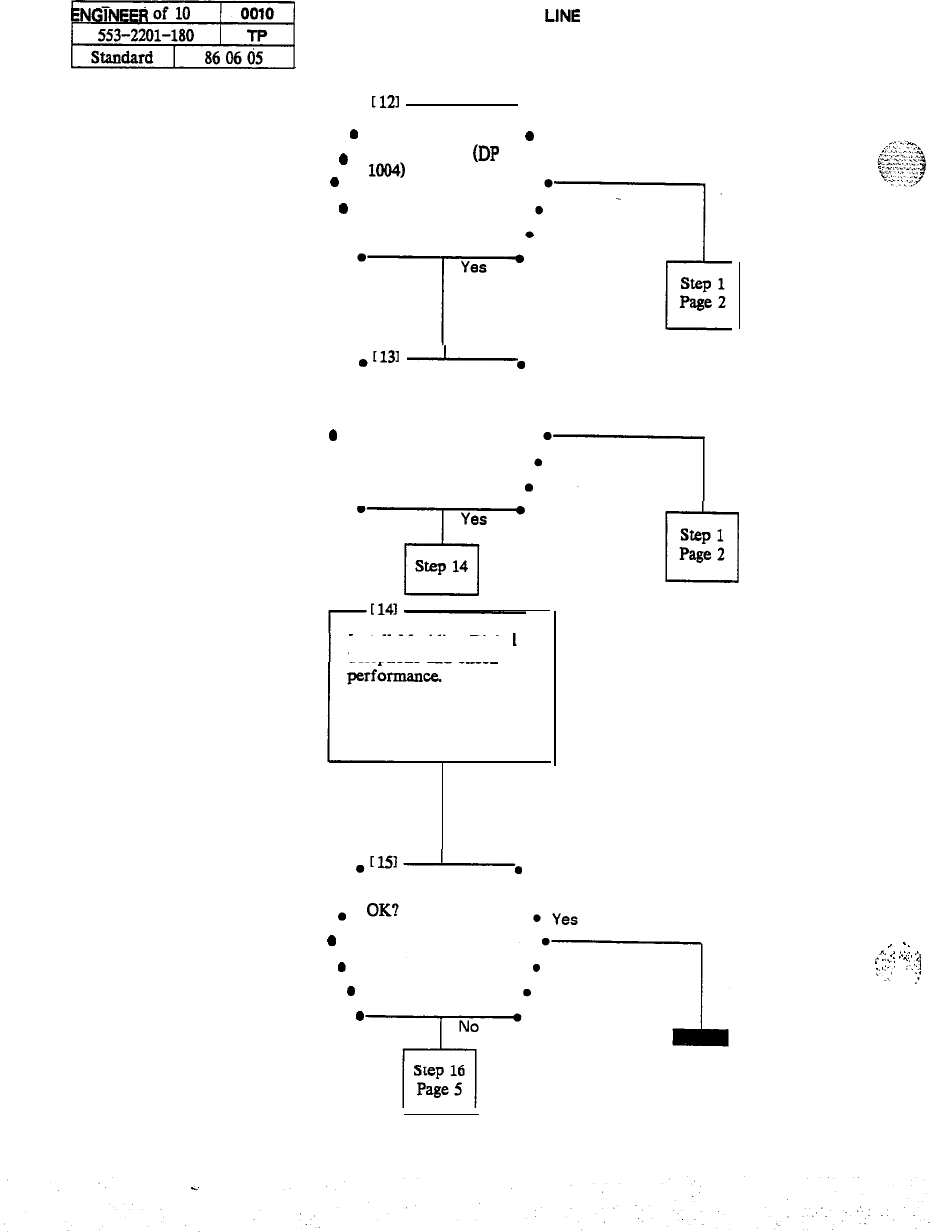
11
ENGINEER
TELEPHONE
LINE
.
[121
.
.
0
.
Is the Impulse noise- 0
within limits? (DP
1004)
. No
0
.
.I131
-.
l
Is the background
l
.
noise within limits?
l No
0
.
l
Install Meridian Digital
Telephone and check
&51-~
l Is the performance l
rl
step 1
Page 2
...
.
_
. .
.
.
.
“.
I
,...-
._
.
. . .
.
..._,.
_I
.
:,...
:
..;:
:‘.
1
~’
::
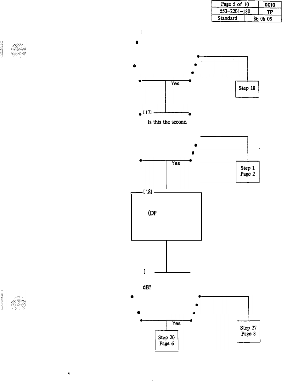
ENGINEER TELEPHONE LINE
pz+Fffj
.
[
161
.
0 Is there another pair
l
. available? . No
.
a
.
cl
step 18
.Wl-.
l
Isthisthesecond
l
. time around? . No
. .
.
0
.
0
-[181
I
Collect more detailed
loop data and calculate
EPL (DP 1006)
l
[
191
.
. Is EPL less than 12.0 .
.
dB?
l No
0
.
0
c
:
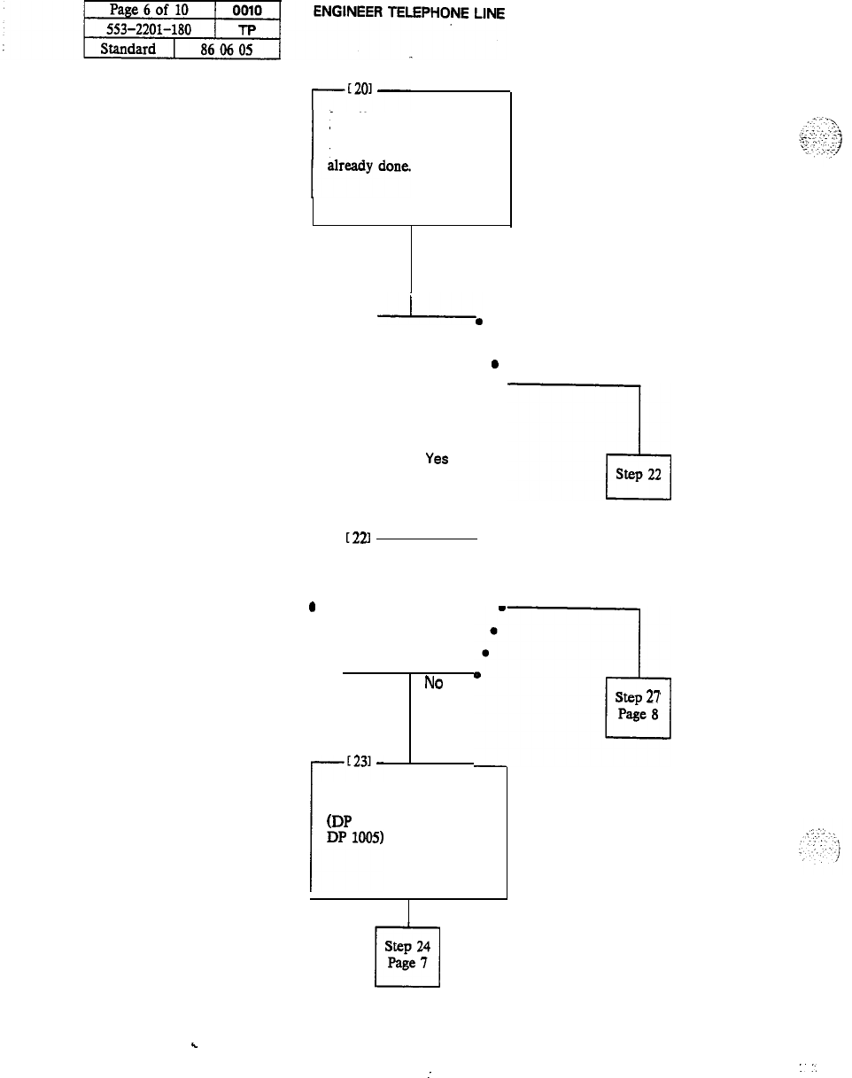
Install Meridian Digital
Telephone and check
performance if not
l
t211
I*
l Is the performance l
. OK?
’
No
..
.
.
A-
.
.
YSS
--A
step 22
.
[22l
.
l
Are the loop
.
l diagnostics and
0
noise measurement
l Yes
already done?
.
.
a
l
0
.
No
q!l
step
21
Page 8
Perform loop diagnostics
and noise measurements.
(DP 1003, DP 1004 and
.
.
Step 24
cl
Page
I
I.
:.
:
. .
ENGINEER TELEPHONE LINE
-1
.
[241
.
l
Are impulse noise
l
. and background
.
noise within limits?
l Yes
l
Is the problem
.
l fixed? l No
.
.
[261
-.
.-
0
Is the performance l
. OK? l No
cl
step
21
Page 8
-1
ENGINEER
TET
LINE
-[2n
Measure the dc loop
resistance. (DP 1007)
l
[281
0
l
Is the loop
.
1[291-,
Install new cable.
resistance less than
l 175 Ohm? . No
..-
.
r--E301
L,
Measure loop insertion
loss at 256 kHz.
l
[311
--J----.
l Is the insertion loss
0
.
less
than 12.0
dB?
l Yes
.
.:.
.
.
.
.
._
.i.
.2
.
.,
._
-
.
ENGINEER TELEPHONE LINE
p%JFffj
Replace any under-carpet
cable if insertion loss can
be reduced.
Install Meridian Digital
Telephone and check
.
[341-.
0
Is the performance
0
. OK? l Yes
..
..
. .
.
No
--I
[
351
At this point there may
be other problems as
listed in Table 0010-A
c

-1
ENGINEER
TEL?
LINE
Table 0010-A
POSSIBLE FAULTS
l
EM1
l
Unrecorded bridge taps
l
Under-carpet cable
l
Split cable pairs
l
Impulse noise
-
not recorded due to speed limitations of the impulse counter.
l
Faulty telephone
.-
c
SELECT A LOOP
-1
NOTES
0.01 The requirements for a Meridian Digital Telephone are that the loop be
without bridge taps, and be less than 175 Ohm dc resistance. and less than 12.0
dB
loss at 256
kHz.
For a single gauge cable, the-length limits are 3000 ft for 22 and
24 AWG cable and D inside wiring, and 2100 ft for 26 AWG cable.
0.02 The allowable loop length assumes that there is no under-carpet cable. If
there is under-carpet cable of a type that is different from Western Electric
4-pair cable, reduce the allowable loop length using the following equation:
. LM
=
I12
-(UC
x
UL)
1
/LL
where
LM
=
loop length limit in km
(kftl
(excluding the length of the under-carpet
cable).
LL
=
loop loss in
dB/km
(dB/Kftl
at 256
kHz.
UC
=
length of the under-carpet cable in km
(kft).
. .
UL
=
loss of the under-carpet cable in
dB/km
(dB/kftl
at 256
kHz.
Refer to
Table 1006-B for
dB-values.

j.
.t...
.\
L..
:.fY
:
:,:.l:,:j
CALCULATE DC LOOP RESISTANCE
pJ%$qy
Chart 1002-l
CALCULATE DC LOOP RESISTANCE
STEP PROCEDURE
1
Calculate the dc loop resistance by adding the resistance of each cable section. Calculate
the resistance of each cable section using the following formula (Cable resistances are
given in Table 1002-A.):
LRi
=
CRi
X
SLi
where:
l
LRi
=
dc resistance for cable section
“i”
l
CRi
=
conductor resistance per unit length for the cable section
“i”
l
SLi
=
length of cable section
“i”
2
Add the total of all cable sections. If the total of all sections exceeds 175 Ohm, select
another loop.
Note: The loop resistance limit of 175 Ohm must be reduced by 1 Ohm for each
1%
of the loop which is aerial cable. .-
::..::..-.:.?
,-;..:,
..:I-,,,’
_.
i,
. .
_
>..,.
..
.
.
,: :.
:
:
.
.

CALCULATE DC LOOP RESISTANCE
Table 1002-A
CONDUCTOR RESISTANCE PER UNIT
Gauge
Ohm per loop kft Ohm per loop km
E
83 52
218
173
22 33 109
19 16
54
PERFORM LOOP DIAGNOSTIC TESTS
p&qFJy
Chart 1
PERFORM LOOP DIAGNOSTIC TESTS
APPARATUS:
01
Volt-Ohmeter
(VOM)
l
1
77 Cable
Analyser
or
eqUiValent
STEP PROCEDURE
FOREIGN VOLTAGE TEST
1
Set the VOM range switch to a scale 60 Vdc/Vac or more.
2
Connect the VOM test probes to the loop at the line card or distributing frame.
3
Measure the dc and ac voltage between the following points under no-load conditions.
l T and R
l T and GND
l Rand GND
Requirement: Voltage readings should be less than 1
Vdc/Vac.
INSULATION RESISTANCE TEST
1
Set the VOM range switch to OhmX1O.OOO and adjust the meter to zero.
2
Connect the VOM test probes to the loop at the line card or distributing frame.
3
Measure the resistance between the following points under no-load conditions.
l T and R
l T and GND
l R and GND
Requirement: Resistance readings should be greater than 10
MOhm.
DC CONTINUITY TEST
1
Short circuit the T and R at the far end.
2
Using the VOM. measure the resistance between the
T
and R.
Requirement: Resistance measurement should be approximately equal to the
calculated loop resistance per DP1002.

PERFORM LOOP DIAGNOSTIC TESTS
Chart 1 Continued
PERFORM LOOP DIAGNOSTIC TESTS
STEP PROCEDURE
CAPACITANCE UNBALANCE TEST
1
Using the 77 Cable Analyser or equivalent, measure the capacitance between the following
points:
l T and GND
l R and GND
Requirement: Difference between the two readings should be
<0.002
microfarads.
.
.
:.
MEASURE IMPULSE NOISE
-1
Chart 1004-l
MEASURE IMPULSE NOISE
STEP PROCEDURE
1
Measure impulse noise on selected lines during busy hours. Use an NE-58B Noise
measurement set, or equivalent.
Note: The termination and weighting filter required are 135 Ohm and 100
kHz
respectively. and the blanking interval 25 microseconds.
2
Using Figure 1004-L Determine that for a given loop loss and noise threshold, the impulse
noise counts per
15
minutes are below the corresponding curve.
Note: The values in Figure 1004-l were derived assuming the counter has a count
rate of 512 pulses per second.
Note: Due to the inaccuracy of the Noise Measuring Set, it is possible that
additional errors may occur during the blanking interval and the reading will
consequently be lower than actual.
. .
::
_:.;
-3
;
^
,
:.
.
.
.
.
._
I
-.,
j
.Z,.”
:
‘.
.
.

1 Page 2 of 2 1 1004 MEASURE IMPULSE NOISE
553-2201-180 1 DP
Standard ) 86 01 27
1000
100
Loss in
di3
Fig. 1004-l
Maximum Allowable Impulse Noise Counts Versus Loop Loss
s.
..:
...
MEASURE BACKGROUND NOISE
-1
Chart 1005-l
1
Measure background noise on the loop using an NE-58B noise measuring set.
Note: The weighting and termination to be used are 100
kHz
flat and 135
Ohm
respectively.
2
Reject the loop being tested if the background noise measured is not less than
5ldBrn.
-

..;:p.
1
::
:
:
.:]
‘:,-.
..
.,i
COLLECT LOOP MAKEUP DATA AND CALCULATE EPL
p%JFfg
Chart 1006-l
COLLECT LOOP MAKEUP DATA AND CALCULATE EPL
(EXPECTED PULSE LOSS)
STEP PROCEDURE
1
3
4
Determine junction loss. (Figure 1006-l)
5
Collect loop makeup data between the line card and the terminal, For each cable section,
the data required is:
the cable type (PIG or pulp)
gauge
length
type of plant construction (underground. aerial,
inbuilding)
Calculate individual cable section losses using the figures in Tables 1006-A. 1006-B,
1006-C. and the following equation.
. .
CSLi
=
SLi
x Li
l
CSLi
=
cable section loss for section “i”.
l
SLi
=
section length of section “i”.
l Li
=
loss per unit length for section “i”. --
Correct individual cable section losses for maximum cable temperature using the following
equation.
TCLi
=
CSLi
x
TCFi
l
TCLi
=
temperature corrected loss for section
“i”
l
TCFi
=
temperature correction factor for section
“i”
CORRECTION FACTORS
Aerial Cable TCF
=
1.1
Underground cable TCF
=
1.04
Inbuilding cable TCF
=
1
Note: Junction loss due to gauge discontinuity of outside plant cables and D-inside
wire varies between 0.03
dB
and 0.07
dB
and can be ignored. However, AMP
25-pair
under-carpet wiring has a characteristic impedance of 40 Ohm at 256
kHz
and its
junction loss is approximately 2
dB.
This must be included in the calculation.
Calculate the EPL by finding the sum of the above items.
COLLECT LOOP MAKEUP DATA AND CALCULATE EPL
Chart 1006-l Continued
COLLECT LOOP MAKEUP DATA AND CALCULATE EPL
(EXPECTED PULSE LOSS)
STEP PROCEDURE
6
Reject loops whose expected pulse loss is not less than 12.0
dB.
EXAMPLE
Section 1:
Mainframe bulkhead to DFl
-
500m. 26 AWG PIC, underground
Section 2:
DFl
to DF2
-
200m.
26 AWG PIC, inside
Section 3:
DF2 to terminal
-
24 AWG NT D-inside
Therefore:
SLl
=
0.5km,
SL2 =
0.2km,
SL3
=
O.lkm
From Tables 1006A and
1006C:
Ll
= 13.7 dB/km. L2 = 13.7 dB/km. L3 = 13.3 dB/km.
Using the equation in Step 2 we arrive at:
CSLl
= 6.85
dB,
CSL2 = 2.74
dB,
and CSL3 = 1.33
dB
Temperature Corrections:
Using correction factors of
TCFl
= 1.04. TCF2 and TCF3
=
1.
and
using the equation in Step 3 results in
TCLl
=
7.12
dB.
TLC2 = 2.14 dB, and TCL3 = 1.33
dB.
EPL Value:
Neglecting any junction loss per explanation in Step 4.
Step 5 results in an EPL value of:
TSLl
+
TSL2
+ TSL3 + 0 = 11.19
dB.
This is under the I2
dB
limit and meets the criteria.
c
COLLECT LOOP MAKEUP DATA AND CALCULATE EPL
Table 1006-A
CABLE ATTENUATION AT 256 KHZ AND 21.1
=‘C
170’
F)’
j
j
i.L:.::.:.-..,
. .._ --..:
:.
26 AWG 24 AWG 22 AWG
19
AWG
,,
,! r-;.~.-.;~.+;
““.
:;
;
,.._.
dB/kft
dB/km
dB/kft
dB/km
dB/kft
dB/km
dB/kft
dB/km
PIG
4.2 13.7 3.1 10.2 2.5 5.6
PULP
.4.3 14.3 3.5 11.4 2.1 6.6
Table 1006-B
ATTENUATION AT 256 KHZ FOR U/C CABLE
WE 4pairs AMP 25 pair
dB/kft
dB/km
dB/kft
dB/km
3.6 15.3 19.0 63.3
Table 1006-C
ATTENUATION AT 256 KHZ FOR D INSIDE WIRING CABLE
NT WE SUPERIOR GENERAL
dB/kft
dB/km
dB/kft
dB/km
dB/kft
dB/km
dB/kft
dB/km
4.0 13.3 3.2 10.7 3.1 13.3 4.6 15.3
*.
.-
-.
‘..-
COLLECT LOOP MAKEUP DATA AND CALCULATE EPL
7 , , , , , , , , ,
6.
5
4
3-
2.
1
0
““““I
20
L
Cable
Characteristic
Impedance in Ohms
Fig. 1006-l
Junction Loss vs Cable Characteristic Impedance
,i
,.
:
:
‘:
_.
,I
.
.
.
.
.
.
a.
::-”
:
3
‘..
.,I
.
.

MEASURE DC LOOP RESISTANCE
p%Jflg
Chart 1007-l
MEASURE LOOP RESISTANCE
STEP PROCEDURE
1
Measure loop resistance using standard procedures.
Note: The dc loop resistance limit of 175 Ohm should be reduced by
1
Ohm for
each
1%
of the total loop that is aerial cable.

..,
. .
.-
-;
.I
:,
..:)
.
.
.
./’
%.
TITLE
CALCULATE DC LOOP RESISTANCE
CHECKLIST
COLLECT LOOP MAKEUP DATA AND CALCULATE EPL
ENGINEER TELEPHONE LINE
INDEX
MEASURE BACKGROUND NOISE
MEASURE DC LOOP RESISTANCE
MEASURE IMPULSE NOISE
PERFORM LOOP DIAGNOSTIC TESTS
SELECT A LOOP
PROCEDURE
NUMBER
DP 1002
CKoooo
DP 1006
TP 0010
Ix 9999
DP
lQo5
DP 1007
DP 1004
,.
DP1003
DP 1001
.-....
.
._.
;
..~,‘-’
:.:c
,‘-.-..
;
.Y’..’
-._...
-‘.
._
.-;.
I
::,
.
.

.
.
:
northem
tdaconl
PRACTICE 553-2201-182
Issued: 85 06 15
Standard
INTEGRATED SERVICES NETWORK
MERIDIAN
SL-1%
SUMMARY OF TRANSMISSION PARAMETERS
CONTENTS PAGE
1.
u-LAW TRANSMISSION PARAMETERS
2.
A-LAW TRANSMISSION PARAMETERS
3.
DTI LOSS TABLES
Tables1-A
1-B
1-C
1-D
1-E
1-F
1-G
1-H
1
-I
1-J
1-K
1-L
1-M
1-N
1-o
1-P
2-A
2-B
2-c
2-D
2-E
2-F
2-G
2-H
2-J
2-K
2-L
2-M
2-N
Insertion Loss at 1020 Hz (““Connections
Between Analog Ports) .................
Frequency Response (Amplitude Distortion)
Overload Levels ......................
Tracking (Linearity) .....................
Transhybrid
Loss ..................
Input Impedance
Idle Channel Noise........... : : :1 :
1.
: : : : : :
Longitudinal
Balance ...................
impulse Noise ........................
Intermodulation Distortion ..............
Envelope Delay Distortion ..............
Quantizatron
Distortion .................
Crosstalk
Return Loss
iDesign
Requirements)’
:
: : : : : :
Return Loss (In-Service Requirements) .....
Harmonic
Dlstortlon
...................
Insertion Loss At 820 Hz ..............
Maximum lnband Amplitude Distortion .....
Return Loss
(Desrgn
Requirements) .......
Return Loss (In-Service Requirements) .....
Distortion and Modulation Products .......
Linearity ...........................
Envelope Delay
Drstortion
...............
Crosstalk .........
OverloadLevels......:::::
::::::::::::
Message Circuit Norse ..................
Impulse Noise .......................
Longrtudinal
Balance ................
Quantrzation
Distortion ..................
l-l
2-l
3-1
l-l
1-l
1-2
1-2
1-2
:
Al-3
l-3
l-3
1-4
1-4
1-4
1-5
l-5
l-5
1-6
1-6
2-l
2-l
2-2
2-3
2-4
2-4
2-5
2-5
2-5
2-6
2-6
:’
2-6
2-7
PRACTICE
553-2201-182
CONTENTS
3-A
3-B
3-c
3-D
1000 Hz Insertion Loss for
ConnectIons
between an Analog Port
and a Digital Trunk Interface
IDTI)
Port
1000 Hz Insertion Loss for Connections’
between Two Ports
of a Digital Trunk interface
(DTI)
_.
1000 Hz Insertion Loss for Connections
between an Analog Port
and a
DigItal
Trunk Interface
IDTI)
Port
for Connections to a Satellite PBX
1000 Hz
InsertIon
Loss for Connections
between Two Ports
of a Digital Trunk Interface
(DTI)
for Connections to a Satellite PBX
PAGE
3-4
3-6
Reason for Reissue: This practice is reissued to include
transmission parameters for the Digital Trunk Interface. and to revise
and add LO the parameters for the Meridian SL-1. Changes have been
marked with bracketing arrows and arrowheads.
,.
-..
.
,:I-
i,:
1.
‘,.
.I
,i
Page ii
PRACTICE 553 -2201-182
1. u-LAW TRANSMISSION PARAMETERS
1.01
The tables in this part provide the transmission requirements which
Meridian SL-1 is
destgned
to meet or exceed in
M-Law
applications.
The specified performance applies in the temperature range of 0 to
50°
C.
1.02 Unless otherwise specified. all specifications are stated in terms of
being met
by
95%
of connections.
Table 1-A
INSERTION LOSS AT 1020 Hz (Connections Between Analog Ports)
+
TYPE OF
CONNECTION
NOMINAL
INSERTION
LOSS
(dB)
LOSS
VARIATION
(dB)
Line-to-Line
5
5 1.0
Line-to-Trunk
1
+0.7
Trunk-to-Trunk
1
50.7
Note: The above loss values apply to connections between analog ports. Port-to-port losses for
c1
connections involving a Digital Trunk Interface
(DTI)
port are given in Part 3.
cl
Table 1-B
FREQUENCY RESPONSE (AMPLITUDE DISTORTION) --
9
Frequency Response in
dB
at the specified frequencies (Hz) for line-to-line, line-to-trunk. or
trunk-to-trunk connections.
FREQUENCY RESPONSE
(dB)
AT FREQ
(Hz)
60 Hz 200
Hz
300 Hz 3000 Hz 3200 Hz 3400 Hz
MIN MAX MIN MAX MIN MAX MIN MAX MIN MAX MIN MAX
+20
-
0.0
+5.0
-0.5 $1.0
-0.5
+1.0
-0.5
f1.5
0.0 $3.0
+I
Note: Values are stated relative to loss at 1000 Hz. The symbol
+
denotes more loss: the symbol
-
denotes less loss than that measured at 1000 Hz.
Page l-l
6 Pages
..
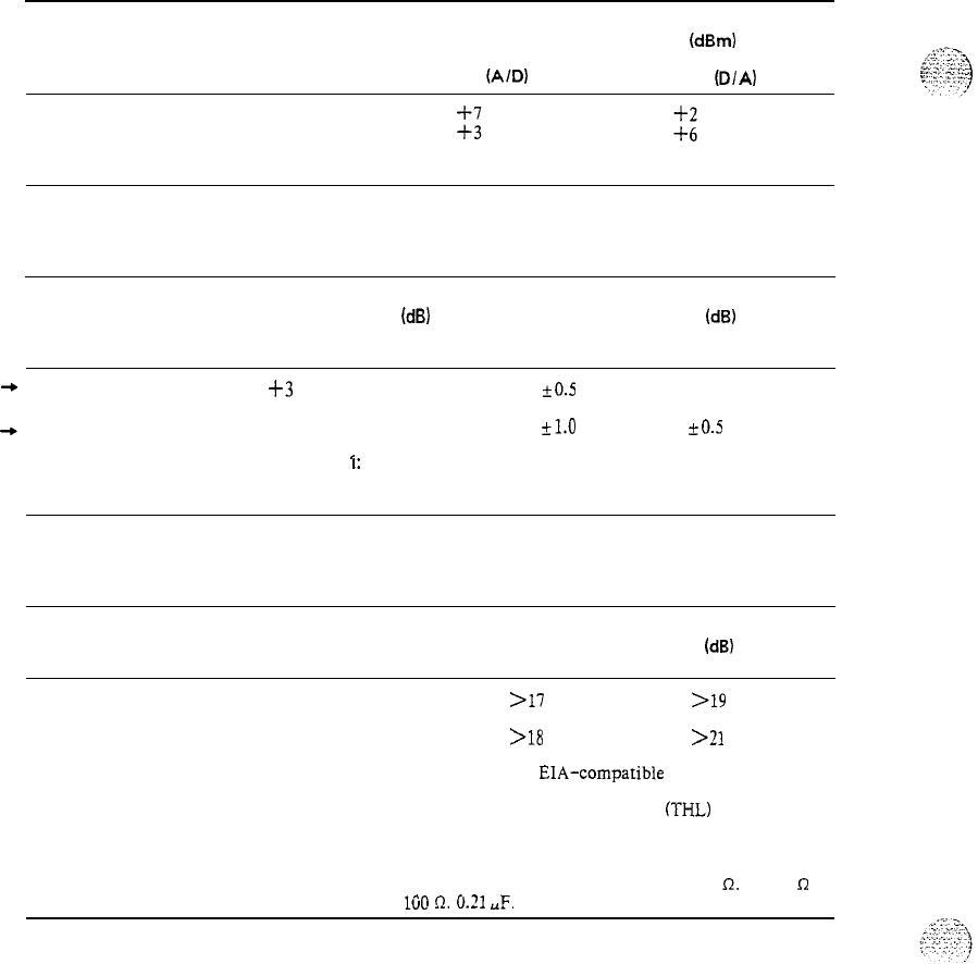
PRACTICE 553-2201-182
Table 1-C
OVERLOAD LEVELS
TYPE OF
CIRCUIT NOMINAL OVERLOAD LEVEL
(dBm)
RECEIVE
(AID)
TRANSMIT
(D/A)
Line
Trunk
Note: Receive and Transmit relate to Switch.
Table 1-D
TRACKING (LINEARITY)
INPUT SIGNAL
(dB)
BELOW OVERLOAD TRACKING ERROR
(dB)
MAXIMUM AVERAGE
+3
to -40
&OS
i-o.25
. .
-40 to -53
k1.0 +0.5
Note
I:
Signal at 1020 Hz.
Note 2: Maximum specification for 99% of all connections.
Table 1-E
TRANSHYBRID LOSS
TWO-WIRE PORT TRANSHYBRID LOSS
(dB)
200 to 3400 Hz 500 to 2500 Hz
Line
>17 >19
Trunk
>18 >21
Note 1: This parameter is for
EIA-compatible
trunks only.
Note 2: Measurement of transhybrid loss
(THL)
is made from
equal-level (transmit and receive) four-wire port towards the
two-wire port.
Note 3: Two-wire port compromise impedance: 600
R.
or 350
R
in
series with
160
Iz.
0.21
UF.
Page l-2
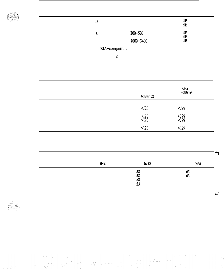
PRACTICE 553-2201-182
Table 1-F
INPUT IMPEDANCE
CONNECTION FROM
REFERENCE
FREQUENCY
4W TRUNK TO PORT IMPEDANCE RANGE
Line 600
R
200-500 Hz
500-3400 Hz
Trunk 600
R
200-500
Hz
500-1000 Hz
1000-3400
Hz
Note 1: This parameter is for
EIA-compatible
trunks only.
Note 2: A reference impedance of 600
R
resistive is used.
MINIMUM
RETURN LOSS
20
dB
26
dB
20 dB
26
dB
30
dB
Table 1-G
IDLE CHANNEL NOISE
CONNECTION
TYPE C-MESSAGE
WEIGHTED
(d8rnC)
3
kHz
FLAT
(d8rn)
Line-Line
Line-Trunk
Trunk-Trunk
<20 <29
<20
at line
<29
at line
<23
at trunk
<29
at trunk __
<20 <29
Table 1-H
LONGITUDINAL BALANCE
FREQUENCY
(Hz)
200
500
1000
3000
MINIMUM
BALANCE
(d8)
:i
AVERAGE
BALANCE
(d8)
:z
63
58
Note:
Measured according to IEEE Standard 455-1983.
Page 1-3
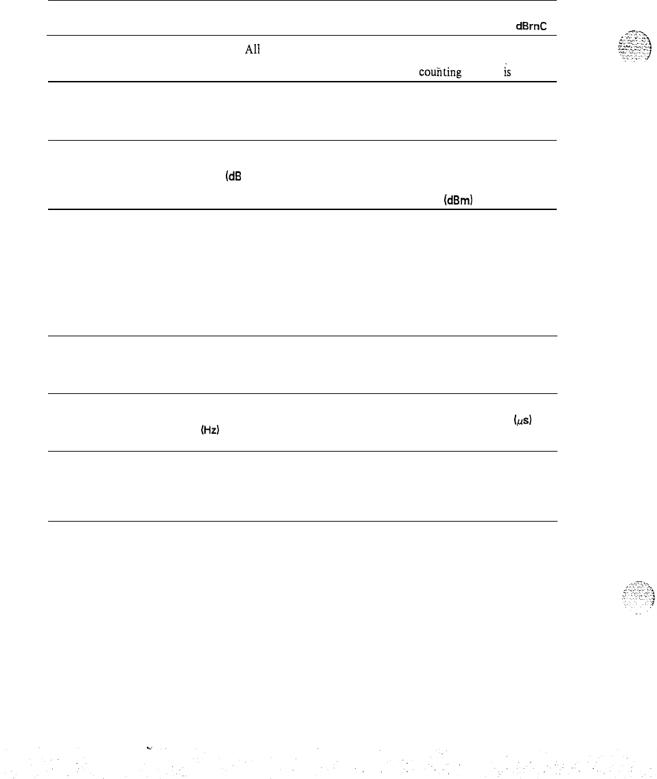
PRACTICE 553-2201-182
Table 1-I
IMPULSE NOISE
CONNECTION NUMBER OF COUNTS ABOVE 55
dBrnC
AH 0
Note: For test purposes. a five-minute
couiiting
interval
is
used.
Table 1-J
INTERMODULATION DISTORTION
CONNECTION
TYPE DISTORTION LIMITS TEST SIGNAL
(dB
BELOW RECEIVED LEVEL) INPUT LEVEL
R2 R3 (dBm)
Line-to-Line
40
Line-to-Trunk
45
Trunk-to-Trunk
45
Note 1: Four-tone method is used.
43
53
53
-9
-9 at line
-13 at trunk
-13
.
.
Note 2: Test Signal Input Level is the composite power level of all four tones.
Table 1-K
ENVELOPE DELAY DISTORTION
BANDWIDTH
(Hz)
ENVELOPE DELAY DISTORTION
(&
LINE-LINE LINE-TRUNK/
TRUNK-TRUNK
800 to 2700 750
.375
1000 to 2600 380
190
1150 to 2300
300 150
Page l-4
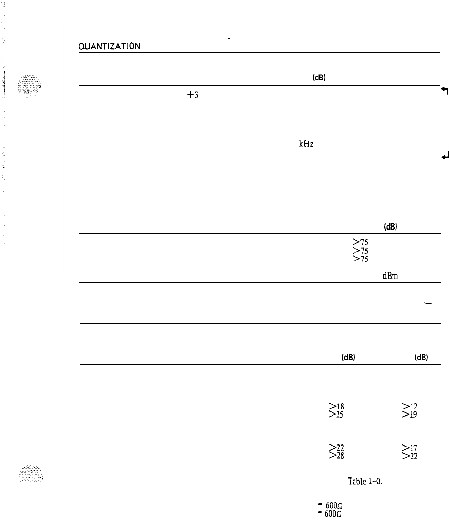
PRACTICE 553-2201-182
Table 1-L
QUANTIZATION
DISTORTION
-
INPUT LEVEL SIGNAL/DISTORTION
BELOW OVERLOAD RATIO
(dB)
+3
to -33
33
+I
-33 to -43
27
-43 to -48
22
Note: Input signal is 1
kHz
sinewave: output measured with
C-message weighting. (See Table 1-C for overload definition.)
4
Table 1-M
CROSSTALK
CONNECTION MINIMUM CROSSTALK
ATTENUATION
(dB)
Line-to-Line
>75
Line-to-Trunk
>I5
Trunk-to-Trunk
>I5
Note: Input frequency range of 200 to 3200 Hz, 0
dBm
level.
Table 1-N
RETURN LOSS (Design Requirements)
.-
CONNECTION
ECHO
SINGING
RETURN RETURN
LOSS
(dB)
LOSS
(dB)
Line Interfaces:
Line Side (Note)
>18 >12
4W Trunk Side (Note)
>25 >19
2W Trunk Interfaces:
2W Trunk Side (Note)
>22 >17
4W Trunk Side (Note)
>28 >22
The design requirements in this table are intended to ensure the
satisfaction of the in-service requirements in
Table
1-O.
Note: Terminating
impedances are:
-
600Q
for SL-1 line
-
600R
for PBX line.
Page l-5
. .
:
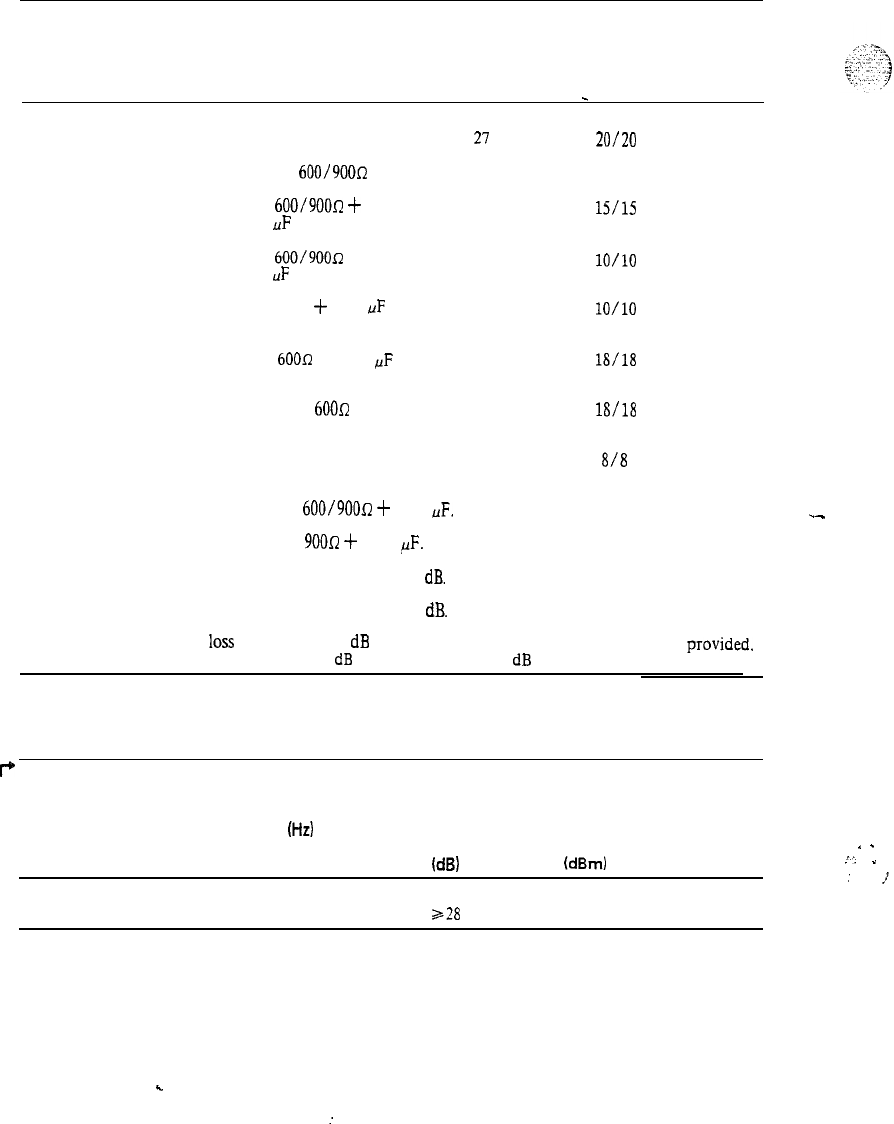
PRACTICE 553-2201-182
Table 1-O
RETURN LOSS (In-Service Requirements)
CONNECTION FROM CIRCUIT
ECHO
LOW/HIGH NOTES
4W VNL TIE TERMINATION RETURN SINGING
TRUNKTOTHE
LOSS
RETURN
FOLLOWING:
_
LOSS
4W VNL Tie Trunk
(through balance) 4W legs of Hybrid
terminated in
600/900R
21
20120
1.3
4W Non-VNL Tie Trunk 600/9OOrr
+
2.16
(terminal balance)
UF
at distant PBX
22
15/U
1.3
2W Non-VNL Tie Trunk
(terminal balance) 600/900R
+
2.16
18
lO/lO 1.5
UF
at distant PBX
CO or FX Trunk (terminal
balance)
PBX Station Line (terminal
balance)
900R
-k
2.16
UF
at
co
60017
+ 2.16
pF
18
lO/lO 2.5
24
18/18 1.4
SL-1 Station Line (terminal
balance) 600R
24
18/18 1.4
PBX Station Line (terminal
Station off-hook
12
818
balance) 1.4
Note 1: Reference impedance is
600/900~
+
2.16
UF.
.-
Note 2: Reference impedance is
900~7
-I-
2.16
,UF.
Note 3: Switchable pads set for nominal loss of 1
dB.
Note 4: Switchable pads set for nominal loss of 3
dB.
Note 5: If facility
loss
is less than 2
dB
or adequate impedance correction is not
provided.
nominal loss has to be increased to 3
dB
by switching in the 2
dB
pad.
Table 1-P
HARMONIC DISTORTION
I+
BANDWIDTH MAX. LEVEL TEST SIGNAL
OF
(Hz)
DISTORTION INPUT LEVEL
PRODUCT
(d8) (dBm)
4
200 to 4600
228
0
.
.
,“.
-
:
,J
Page l-6
.
:
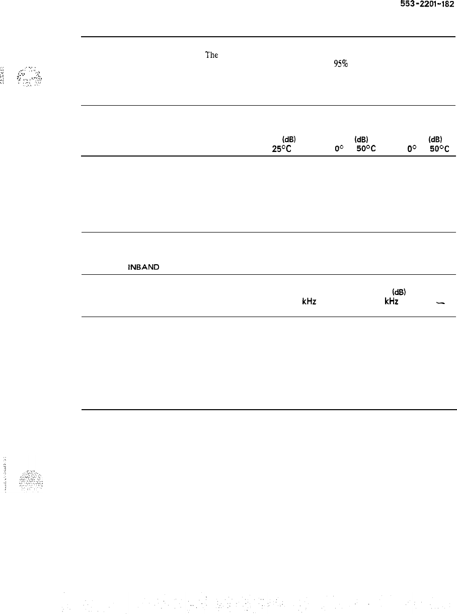
PRACTICE
553-2201-182
2. A-LAW TRANSMISSION PARAMETERS
2.01
The
tables in this part provide the transmission requirements which
Meridian SL-1 is designed lo meet on
95%
of all connections in A-Law
:;*;
_
:
-;
.:
,.
. . . .
..\
I
.._.
. . .
.1
:’
.I
._
applications.
z:i
r,
. . .
Ijl,.
:
y.;
;y;
Table 2-A
INSERTION LOSS AT 820 HZ
TYPE OF
CONNECTION
NOMINAL MAXIMUM MINIMUM
INSERTION INSERTION INSERTION
LOSS
(d6)
LOSS
(dB)
LOSS
(dB)
at
25%
at
O”
to
50°C
at
O”
to
50%
Station
line-to-line
5 6
4
Station
line-to-trunk
1
20
Trunk-to-trunk 1
2 0
Table 2-B
MAXIMUM
INBAND
AMPLITUDE DISTORTION
CONNECTION AMPLITUDE DISTORTION
(dB)
0.2
kHz
3.4
kHz
MIN MAX MIN MAX
-
Line-to-line -0.5
3.5 0.0 3.5
Trunk-to-trunk
0.0 3.0 0.0 3.0
Trunk-to-line
0.0 4.0 0.0 3.0
Note: Performance limits quoted apply to 95% of all
connections.
Page 2-1
7 Pages
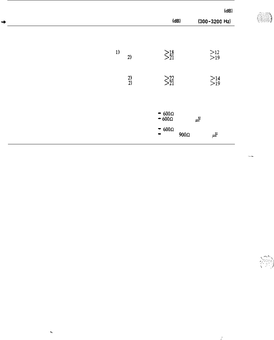
PRACTICE 553-2201-182
Table 2-C
RETURN LOSS (Design Requirements)
CONNECTION
ECHO
RETURN
LOSS
(d8)
SFRL LOSS
id81
(300-3200
Hz)
Line Interfaces:
Line Side (Note
1)
4W Trunk Side (Note 2)
2W Trunk Interfaces:
>18 >12
>21 >19
2W Trunk Side (Note 2)
>22 >14
4W Trunk Side (Note
2)
>21 >19
The design requirements in this table are intended to ensure the
satisfaction of the in-service requirements in Table 2-D.
Note 1:
Terminating impedances
are:
Note 2: Terminating
impedances are:
-
6OOQ
for SL-1 line
. .
-
60012
and 2.16
UF
for PBX.
-
60012
for SL-1 line
-
600 or
900R
and 2.16
pF
for
PBX line.
*.-..
L
.~
_
:;-,
1
:.
. .
..
.I
;
:
Page 2-2
.
.
.:
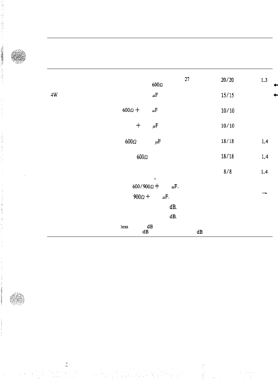
PRACTICE 553-2201-182
Table 2-D
RETURN LOSS (In-Service Requirements)
CONNECTION FROM CIRCUIT
ECHO
LOW/HIGH NOTES
4W VNL TIE TERMINATION RETURN SINGING
TRUNK TO THE
LOSS
RETURN
FOLLOWING:
LOSS
4W VNL Tie Trunk 4W legs of Hybrid
(through balance)
terminated in
600~
21
20/20
I,3
c
4W
Non-VNL Tie Trunk
(terminal balance)
600R •k 2.16
,AF
at
distant PBX
22
15/u
1.3
+
2W Non-VNL Tie Trunk
(terminal balance) 600R
i-
2.16
uF
at
distant PBX
18
lO/lO
1.5
CO or FX Trunk (terminal
balance)
900R
-k
2.16
,uF
at
co
18
lO/lO
2.5
PBX Station Line (terminal
balance)
SL-1 Station Line (terminal
balance)
600R
+ 2.16
,uF
24 18/18 1.4
600R 24 18/18 1.4
PBX Station Line (terminal
balance)
Station off-hook
-:
12
8/8 I,4
Note 1: Reference impedance is
600/900R
-I-
2.16
uF.
.-
Note 2: Reference impedance is
90011
i-
2.16
uF.
Note 3: Switchable pads set for nominal loss of 1
dB.
Note 4: Switchable pads set for nominal loss of 3
dB.
Note 5: If facility loss is
less
than 2
dB
or adequate impedance correction is not provided,
nominal loss has to be increased to 3
dB
by switching in the 2
dB
pad.
Page 2 -3
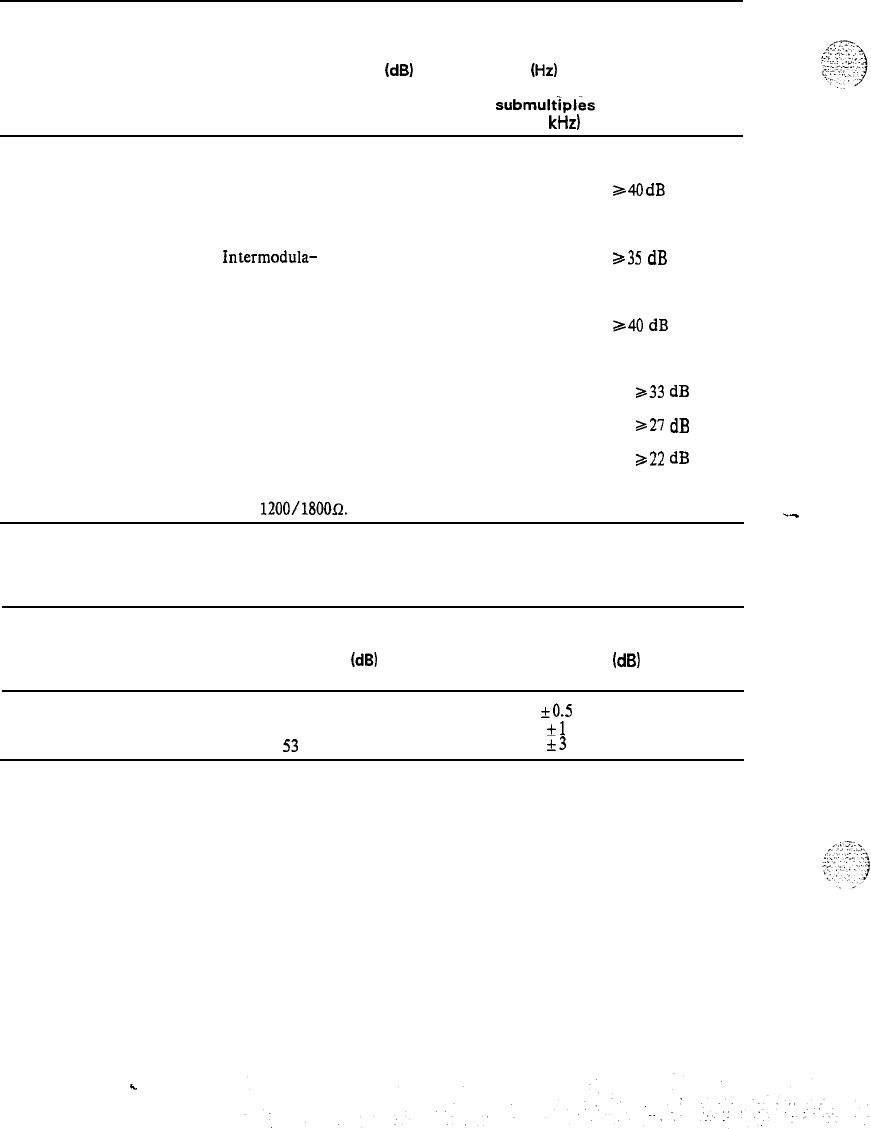
PRACTICE 553-2201-182
Table 2-E
DISTORTION AND MODULATION PRODUCTS
DISTORTION
TYPE INPUT
LEVEL
(d8)
BELOW
OVERLOAD
INPUT MAXIMUM
FREQUENCY/s
LEVEL
(Hz)
OF DISTORTION
(excluding PRODUCT
submultiples
of 8
kHz)
Harmonic
3
700-1100
340
dB
below
fundamental
output signal
Intermodula-
tion
13
300-3400
(see Note)
a35
dB below
fundamental
output signal
Sideband
3
700-1100
340
dB below
Suppression fundamental
output signal
.
.
Quantization o-33 700-1100
333
dB
33-43 700-1100
321
dB
43-48 700-1100
322
dB
Note: Using two oscillators. each with an output impedance of
1200/1800~.
.-
Table 2-F
LINEARITY
820 Hz SIGNAL
INPUT LEVEL
(dB)
BELOW OVERLOAD
VARIATION IN
INSERTION LOSS
(dB)
0
to
43
kO.5
43
to
53
?rl
53
to
58
k3
Page 2-4
.
.
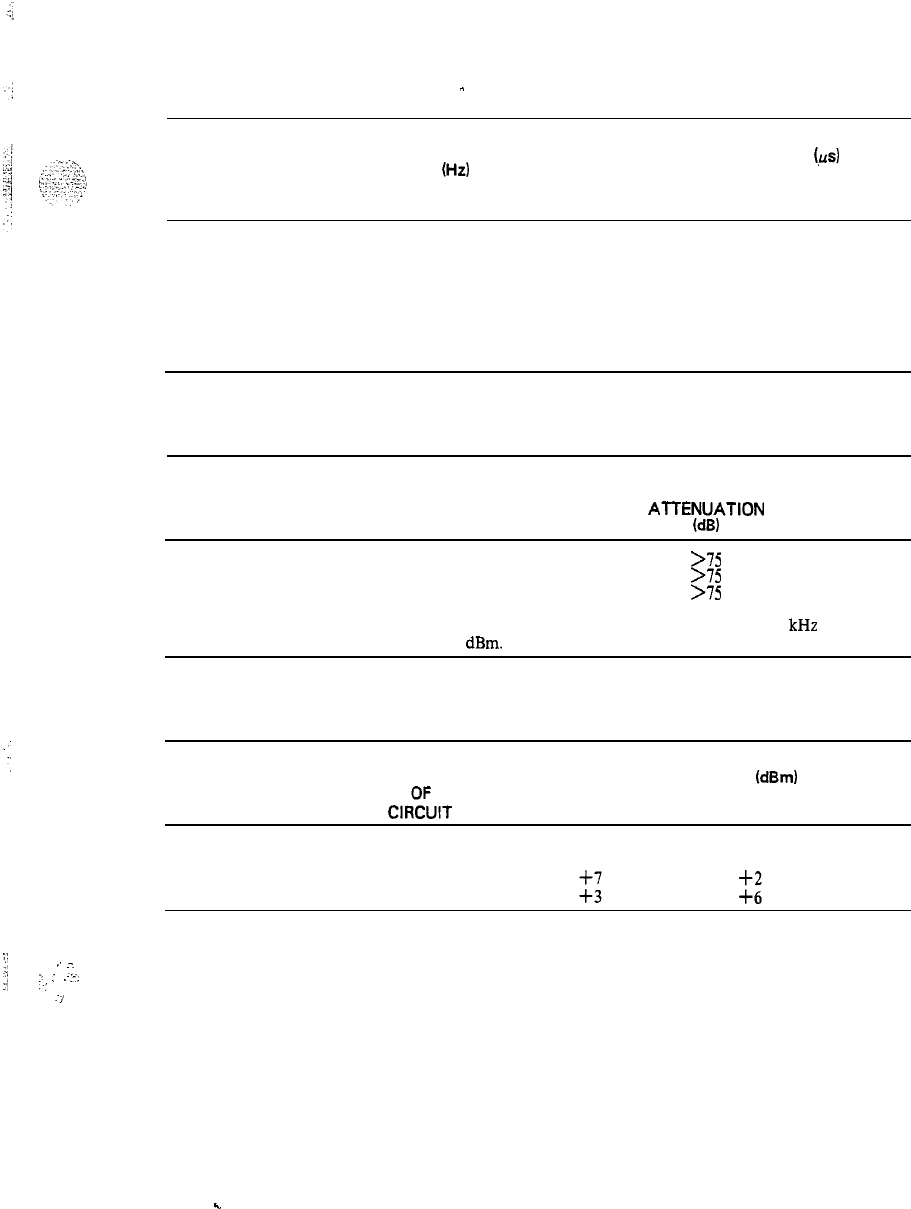
PRACTICE 553-2201-182
Table 2-G
-
ENVELOPE DELAY DISTORTION
BANDWIDTH
(Hz)
ENVELOPE DELAY DISTORTION
(,us)
LINE-LINE LINE-TRUNK/
TRUNK-LINE/
TRUNK-TRUNK
1000
to 2600
380 190
1150
to 2300
300 150
800 to 2700 750
375
Note:
The limits above apply to 95% of all connections.
Table 2-H
CROSSTALK
CONNECTION CROSSTALK
AlTENUATlON
(dB)
Line-to-Line
>75
Line-to-Trunk
>75
Trunk-to-Trunk
>75
Note: Frequency range of test signal 0.2 to 3.4
kHz
at
-10
dBm. __
Table 2-J
OVERLOAD LEVELS
TYPE NOMINAL OVERLOAD LEVEL
(dBm)
CIROC’UIT
TRANSMIT
RECEIVE
Line
Trunk
::
il
;
‘.
7
y/ :.
;
.:-.
,.;
-/
Page 2-5
.
.

PRACTICE 553-2201-182
Table 2-K
MESSAGE CIRCUIT NOISE
CONNECTION
NOISE LEVEL
dl3mOp dBrn
3
kHz
FLAT
Line-to-Line
Line-to-Trunk:
G-65 ~29
(a) Trunk side
(b)
Line side
Trunk-to-Trunk
(2 dB pads out)
6-65
<29
~-65
629
e-65
~29
Table 2-L
IMPULSE NOISE
With all circuits at the MDF correctly terminated. the impulse noise measured at line terminals should
be as follows.
NOISE
LEVEL
(d8)
COUNTS
-
50
<5
counts/S min for
50%
of the connections
50
GO0
counts/5 min for all connections
59
<5
count.45 min for all connections
Table 2-M
LONGITUDINAL BALANCE
FREQUENCY
(Hz)
MINIMUM
BALANCE
(d8)
AVERAGE
BALANCE
(dB)
200
58
500
66:
1000
::
3000
53 Fi;
cl
Page 2-6
,
z-.x
.‘,Y
:‘;.
<.\\
.-_
.
1
:: .:.. _
:_
_‘I
-1
,
..d

PRACTICE 553-2201-182
Table 2-N
ClUANTlZATlON
DISTORTION
-
INPUT LEVEL SIGNAL/DISTORTION
BELOW OVERLOAD RATIO
(dB)
3 to 33
33
33 to 43
21
43 to
48
22
Note: Input signal is 820 Hz sinewave: output measured with
psophometric weighting. (See Table 2-J for a definition of
overload.)
cl
Page 2-7

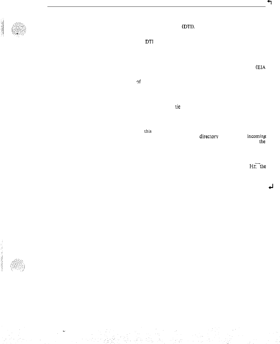
PRACTICE 553-2201-182
3. DTI LOSS TABLES
+I
3.01 Tables 3-A through 3-D provide the insertion loss specifications of
the SL-1 Business Communications System when it is equipped with a
QPC472 Digital Trunk Interface (DTI).
3.02 The insertion loss for connections between analog ports of the
SL-1 and the
DTl
or beteween DTI ports is connection-specific in
order to be compatible with end-to-end network connection loss
requirements. SL-1’ connection loss specifications are in agreement with
U.S. and Canadian standards which are formulated to provide
satisfactory transmission on connections between switches in a *private
network and between a private network and the public network.
(EIA
Communications Interim Standard. CIS-4 (U.S.); Department of
Communications Standard CS-03 (Canada).) This formulation is based
on the use
Qf
a fixed loss plan for digital portions of these connections.
As a result. certain connections through the SL-1 are asymmetrical: this
asymmetry is resolved at the far end of the connection.
3.03 Tie trunk connections to a satellite PBX require different loss
treatment than non-satellite
Lie
trunks. The insertion loss for satellite
tie trunk connections is given in Tables 3-C and 3-D. Loss values
associated with tie trunks in Tables 3-A and 3-B should not be applied
to satellite PBX tie trunk connections.
. .
Note: In
this
NTP. “satellite” denotes a PBX which homes on a
main PBX and does not have a
directorv
number for
incoming
calls: satellite tie trunks are trunks connecting such a PBX to
the
main PBX. There is no explicit or implied reference to facilities
usuing satellite (i.e.. space vehicle) circuits.
3.04 In these tables. the notation “1000 Hz Insertion Loss” refers to a
sinusoidal signal having a frequency between 1000 and 1020
Hzrthe
value of 1004 Hz has been standardized in the telephone industry in
order to avoid frequency beating of an exact 1000 Hz signal in the
presence of PCM carrier systems.
Page 3-1
6 Pages
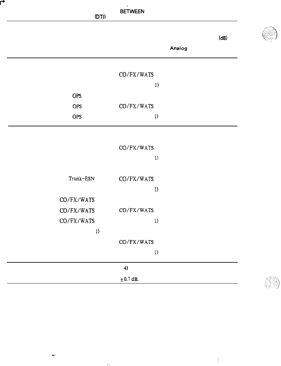
PRACTICE 553-2201-182
I+
Table 3-A
1000 Hz INSERTION LOSS FOR CONNECTIONS
BEiWEEN
AN ANALOG PORT
AND A DIGITAL TRUNK INTERFACE
(DTI)
PORT
TYPE OF ANALOG
CONNECTION PORT DIGITAL
PORT
NOMINAL
INSERTION LOSS
(dB)
Analbg
port DTI to
to DTI Analog port
Station to
Trunk Local Station Tie Trunk
3 9
Local Station
CO/FX/WATS
33
Local Station Toll WATS (Note
1) 3 9
OPS Tie Trunk
06
OF5
CO/FX/WATS
0 0
OF5 Toll WATS (Note
1) 0
6
Trunk to
Trunk Tie Trunk
Tie Trunk
Tie Trunk
Tie Trunk-ESN
Tie
Trunk-ESN
Tie Trunk-ESN
CO/FX/WATS
CO/FX/WATS
CO/FX/WATS
Toll WATS (Note
1)
Toll WATS (Note 1)
Toll WATS (Note 1)
Tie Trunk
CO/FX/WATS
Toll WATS (Note
1)
Tie Trunk
CO/FX/WATS
Toll WATS (Note
1)
Tie Trunk
CO/FX/WATS
Toll WATS (Note
1)
Tie Trunk
CO/FX/WATS
Toll WATS (Note
1)
-2
3
-2
-2.5
2.5
-2.5
0
0
0
-3
3
0
4
3
4
3.5
2.5
3.5
6
0
6
3
3
6
Note 1:
Toll WATS is a trunk to a Toll (Class 4) office for WATS access.
Note 2: Insertion loss limits are nominal loss
f0.7
dB.
4
Page 3-2
s.
:
:
.
.
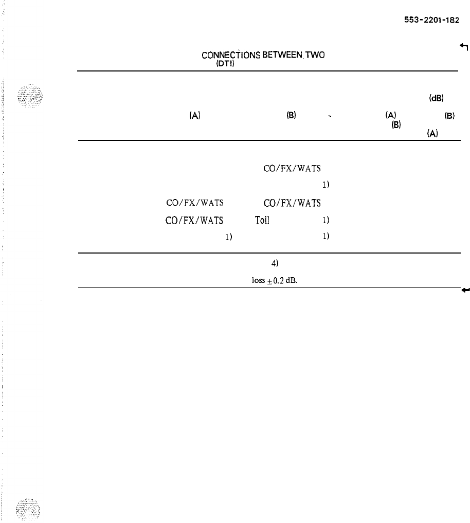
PRACTICE
553-2201-182
Table 3-8
1000 Hz INSERTION LOSS FOR
CONNECilONS
BETWEEN.TWO
PORTS
+I
OF A DIGITAL TRUNK INTERFACE
(DTI)
TYPE OF
CONNECTION DIGITAL
PORT
(A)
NOMINAL
DIGITAL INSERTION LOSS
(d8)
PORT
(B)
-
DTI port’
(A)
DTI port
(B)
to DTI port
(B)
to DTI port
(A)
Trunk to
Trunk Tie Trunk Tie Trunk
0 0
Tie Trunk
CO/FX/WATS
6 0
Tie Trunk Toll WATS (Note
1) 0 0
CO/FX/WATS CO/FX/WATS
3
3
CO/FX/WATS
Toll WATS (Note
1) 0 6
Toll WATS (Note
1)
Toll WATS (Note
1) 0
0
Note 1:
Toll WATS is a trunk to a Toll (Class 4) office for WATS access.
Note 2: Insertion loss limits are nominal
loss
+0.2
dB.
Page 3 -3
. .
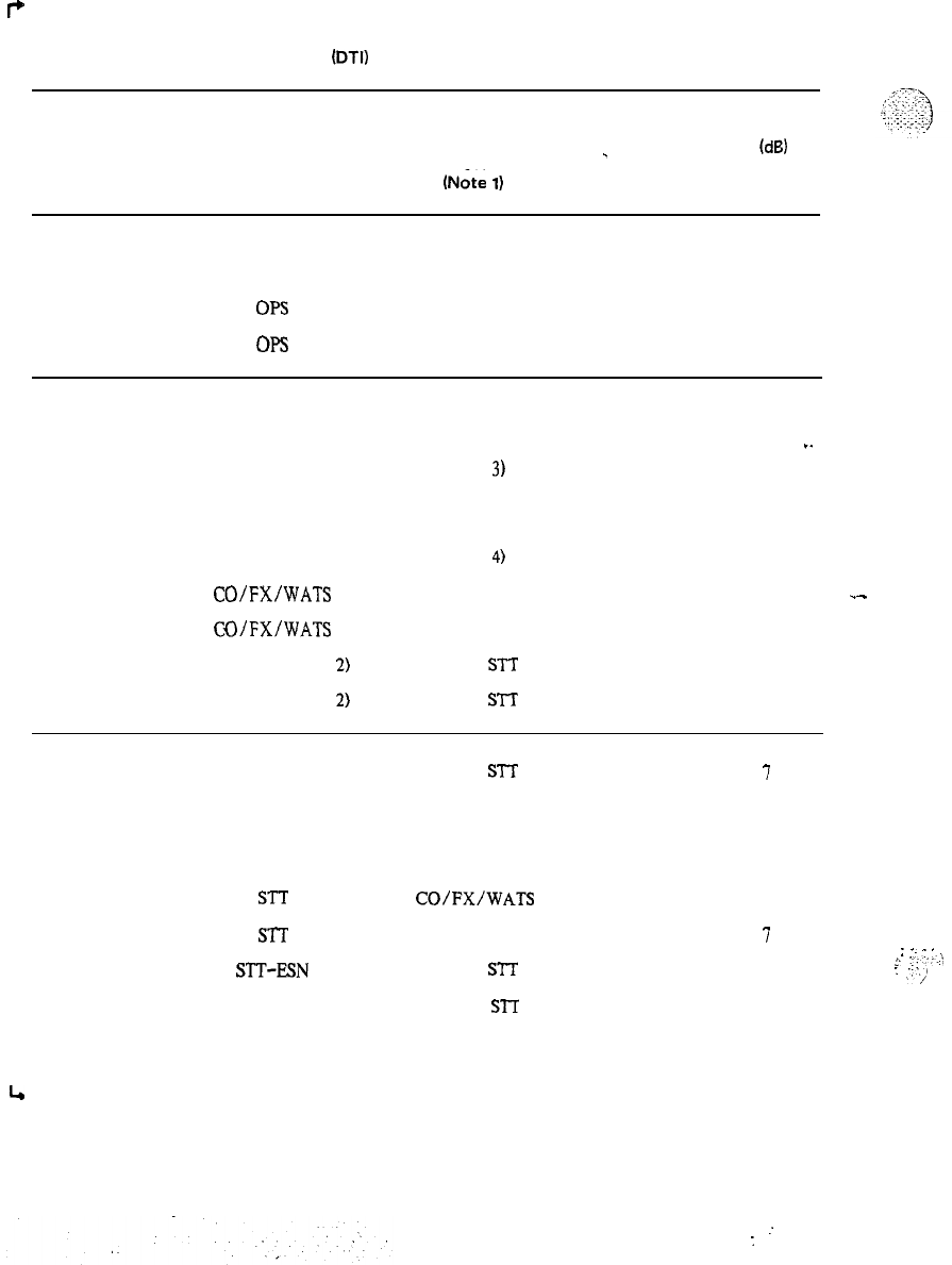
PRACTICE 553-2201-182
P
Table 3-C
1000 Hz INSERTION LOSS FOR CONNECTIONS-BETWEEN AN ANALOG PORT
AND A DIGITAL TRUNK INTERFACE
(DTI)
PORT
FOR CONNECTIONS TO A SATELLITE PBX
TYPE OF ANALOG
CONNECTION PORT
Station to
Satellite
Tie Trunk
Local Station
Local Station
DIGITAL
PORT
(Note
1)
Comb. STT
Digital STT
NOMINAL
_
INSERTION LOSS
(dB)
Analog port DTI to
to DTI Analog port
3 9
3 3
OPS Comb. STT
06
OP.3
Digital STT
2 2
Non-satellite
Trunk to
Satellite
Tie Trunk
Tie Trunk
Tie Trunk
Tie Trunk-ESN
Tie Trunk-ESN
CO/FX/WATS
CQ/FX/WATS
Toll WATS (Note 2)
Toll WATS (Note 2)
Comb. STT
Digital STT
(Note
3)
Comb. STT
Digital STT
(Note
4)
Comb. STT
Digital STT
Comb.
STT
Digital
S’lT
-2
3
4
3I.
-2.5
2.5
-3
0
-3
3
3.5
2.5
3
_-
0
3
3
Satellite
Tie Trunk to
DTI Trunk
STT
STT
STT
STT
STT
SIT-ESN
STT-ESN
STT-ESN
4
Page 3-4
Comb.
STT
Digital STT
Tie Trunk
(non-satellite)
CO/l=X/WATS
Toll WATS (Note 2)
Comb.
STT
Digital
STT
Tie Trunk
hoc-satellite)
1
I
1
1
1
7
1
1
1
I
0.5 6.5
0.5 0.5
0.5 6.5
:
.-
:
.
.
L
,......!
.,
:
..,I
:
:

.
PRACTICE 553-2201-182
Table 3-C Continued
1000 Hz INSERTION LOSS FOR CONNECTIONS BETWEEN AN ANALOG PORT
AND A DIGITAL TRUNK INTERFACE
(DTI)
PORT
FOR CONNECTIONS TO A SATELLITE PBX
TYPE OF ANALOG
CONNECTION PORT DIGITAL
PORT
-
(Note
1)
NOMINAL
INSERTION LOSS
(d8)
Analog port DTI to
to DTI Analog port
STT-ESN
STT-ESN
CO/FX/WATS
0.5 0.5
Toll WATS (Note 2) 0.5 6.5
Note
1:
DTI
port to Combination or Digital Satellite Tie Trunks
KIT)
unless otherwise noted.
Note 2: Toll WATS is a trunk to a Toll (Class
4)
office for WATS access.
Note 3: Optionally. 1
dB
loss each direction may be specified. provided the satellite PBX does not
serve OPS lines.
Note 4: Optionally. 0.5
dB
loss each direction may be specified, provided the satellite PBX does
not serve OPS lines.
Page 3-5
I
.
.
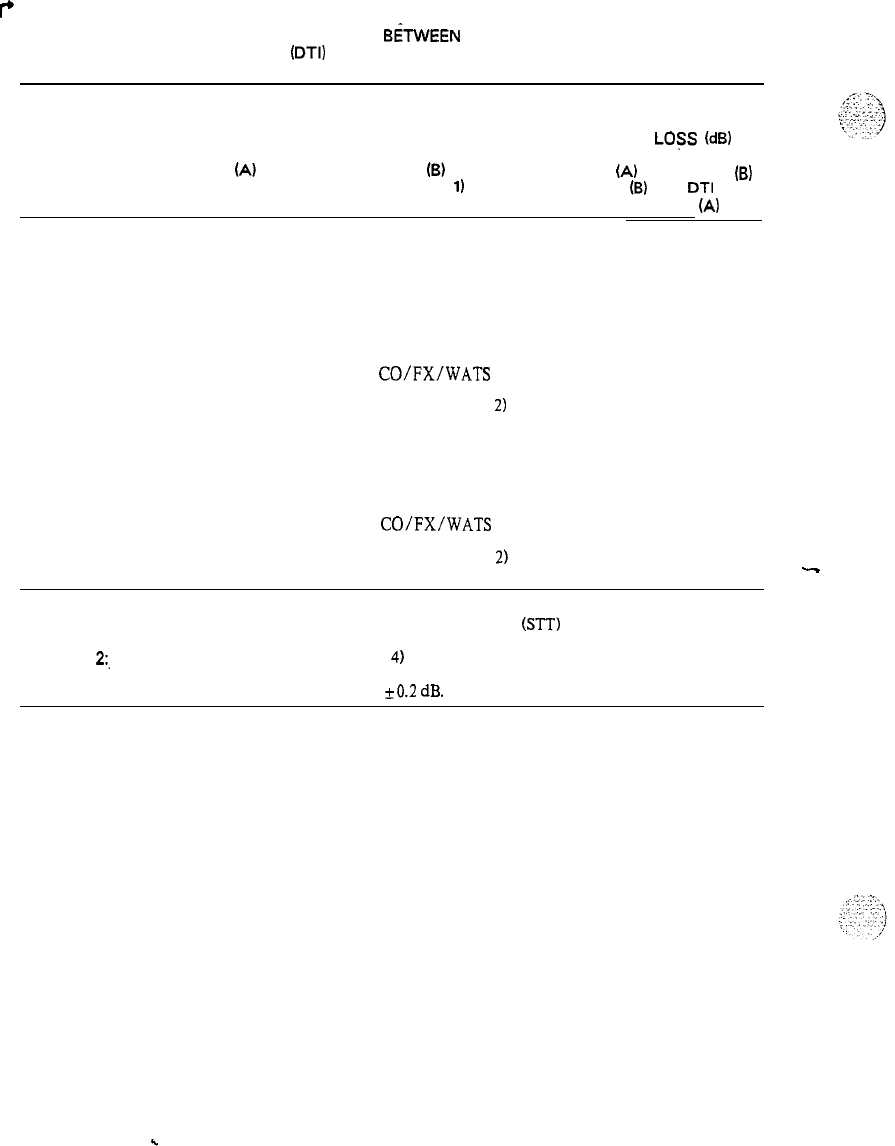
PRACTICE 553 -2201-182
r
Table 3-D
1000 Hz INSERTION LOSS FOR CONNECTIONS
BiTWEEN
TWO PORTS
OF A DIGITAL TRUNK INTERFACE
(DTI)
FOR CONNECTIONS TO A SATELLITE PBX
TYPE OF
CONNECTION DIGITAL DIGITAL
PORT PORT
(A)
(8)
(Note 1) (Note
1)
NOMINAL
INSERTION
LOSS
(dB)
DTI port
(A)
DTI port
(B)
to DTI port
(B)
to
DTI
port
(A)
Satellite
Trunk to
Trunk Comb. STT
Comb. STT
Comb. STT
Comb. STT
Comb. STT
Digital STT
Digital STT
Digital STT
Digital STT
Comb. STT
Digital STT
Tie Trunk
(non-satellite)
CO/FX/WATS
Toll WATS (Note
2)
Digital STT
Tie Trunk
(non-satellite)
CO/FX/WATS
Toll WATS (Note
2)
00
60
00
60
00
00
0
6
00
06
Note 1:
DTI port to Combination or Digital Satellite Tie Trunks (STT) unless otherwise noted.
Note
2:.
Toll WATS is a trunk to a Toll (Class
4)
office for WATS access.
4Note 3: Insertion loss limits are nominal loss
+0.2
dB.
Page 3-6
-
.
.
SL-1
System options
21,51,61,71
Analog line card description
Standard
nit
norf
horn
tulacom
Meridian
I

.

SL-1
System options
21,51,61,71
Analog line card description
Publication number: 553-3001-l 61
Document release: 1 .O
Document status: Standard
Date: January
29,199O
-
0
1990 Northern Telecom
All rights reserved.
Analog line card description 553-3001-l 61
.
.
. .
.
.

ii
Revision history
January 29,199O
Standard, release 1 .O
Analog line card description 553-3001-l 61
iii
About this document
This practice outlines the characteristics, application, and operation of the
NTI3DO3AB Analog Line Card. The information is intended to be used as a
guide when connecting customer-provided apparatus to the line circuit.
New naming conventions are applied to this release. The following
documents should be used as references to this document:
References
See. the SL-I planning
&
engineering guide
for
-
Master index
(553-3001-000)
-
System overview
(553-3001-100)
-
System engineering
(553-3001-151)
-
Sparesplanning (553-3001-153)
-
Equipment identification and ordering
(553-3001-M)
See the list of line and trunk circuit descriptions in the
Master index
(553-3001-000) for specific references to lines and trunks.
See the SL-1 installation and maintenance guide
for
-
Circuit pack installation and testing
(553-3001-211)
-
Fault clearing (553-3001-510)
-
Hardware replacement
(553-3001-520)
See the
SL-1 XII sofhvare guide
for an overview of software architecture,
procedures for software installation and management, and a detailed
description of all Xl 1 features and services. This information is contained
in two documents:
Analog line card description 553-3001-161
iv About this document
-
XII software management
(553-3001-300)
-
XII features
and
services (553-3001-305)
See the SL-I XII input/output guide
(553-3001-400) for a description of alI
administration programs, maintenance programs, and system messages.
See the following Northern Telecom Publications for references to specific
telephone sets:
-
Meridian M2ooO digital telephones: description, installation,
operation and maintenance
(553-2201-110)
-
Meridian M2317 digital telephone with alphanumeric display:
description , installation, operation, and maintenance
(553-2201-113
-
Meridian M3000 touchphone: description, installation, operation and
maintenance
(553-2201-115)
-
Meridian modular telephones: description and speci&ztions
(553-2201-116)
Analog line card description
553-3001-l 61
. .
:.

V
Contents
General information
Application 2
Characteristics 3
Functional
I.
3
Technical summary 4
Analog line interface
4
Input impedance 4
Insertion loss 4
Frequency response 4
Message channel noise
5
Power requirements 6
Foreign and surge voltage protections
, 6
Overload level 6
Analog line card description 553-3001-l 61
.
.
:

vi Contents
Analog line card description 553-3001-l 61
General information
1
This publication outlines the characteristics, application and operation of the
Analog Line Card. The information is intended to be used as a guide when
connecting customer-provided apparatus to the line circuit. The following
Analog Line Card is available:
-
NT8DO3AB
-
Analog Line Card (p-Law)
The Analog Line Card provides talk battery and signaling for regular 2-wire
common battery 500~type (rotary dial), 2500~type (DIGITONE dial)
telephones and key telephone equipment.
Note:
DIGITONE is a trademark of Northern Telecom.
.-
The NT8DO3AB Analog Line Card mounts in an NT8D37AA Intelligent
Peripheral Equipment Module (IPE). The circuit connects with the
switching system and with the external apparatus via an 80-pin connector at
the rear of the pack. The pack is 3 18 mm (12.5 in) in height and 254 mm
(10 in) in depth.
The circuits are connected to the shelf backplane and fed to the I/O panel
via I/O cables. Fron the I/O panel, the circuits are connected to the cross-
connect terminal via 25-pair cables. Connection to the station apparatus is
made at the cross-connecting terminal.
Analog line card description 553-3001-l 61
.,
2 Summary
Application
-
The line circuit interfaces and is compatible with the equipment listed in
Table 1.
Table 1
Line circuit application and compatibility
Equipment Specifications
NE-500 type rotary dial
sets (or equivalent)
Dial Speed 8.0 to 22.5 pps
Percent Break 58 to 70%
Interdigital Time 240 ms
NE-2500 type Digitone sets
(or equivalent)
Frequency Accuracy
+
1.5 %
Pulse Duration 40 ms
Interdigital Time 40 ms
Speed 12.5 digits/s
Analog line card description 553-3001-l 61
Summarv
3
Characteristics
Functional
The Analog Line Card contains an 8050 microprocessor that provides the
following functions:
-
card self-identification
-
self-test
-
control card operation
-
status report to the controller
-
diagnostics for maintenance purposes
The Analog Line Card also provides the following:
. .
-
6OOQ
balanced terminating impedance
-
analog-to-digital and digital-to-analog conversion of transmission and
reception signals for 16 audio phone lines
-
transmission and reception of SSD signalling messages over a DS30X
signalling channel in A10 format
--
-
detection of on-hook/off-hook status
-
connection of 20 Hz ringing signal and automatic disconnection when
the station goes offhook
-
synchronization for connecting and disconnecting the ringing signal to
zero crossing of ringing voltage
-
loopback of SSD messages and PCM signals for diagnostic purposes
-
indication of board status with faceplate-mounted LED
-
correct initialization of all features at power-up
-
direct reporting of digit dialed (500 sets) by collecting dial pulses
Analog line card description 553-3001-l 61
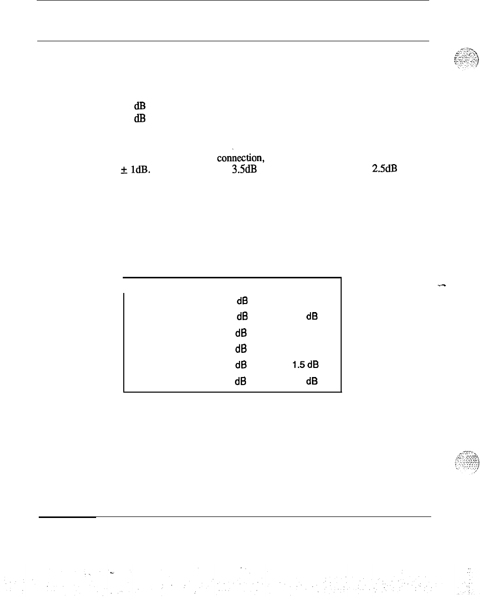
4 Summary
Technical summary
Analog line interface
Input impedance
The impedance at tip and ring is 600 Ohm with a return loss of
20 dB for 200-500 Hz
26
dl3
for 500-3400 Hz
Insertion loss
On a station line-to-line
conkction,
the total insertion loss at 1 KHz is 6dB
+
1dB. This is arranged as 3.5dB loss for analog to PCM and 2.5dB loss for
PCM to analog.
Frequency response
The
loss values in the table below are measured relative to the loss at 1
KHz:
Table 2
Frequency response
Frequency Minimum Maximum
60
Hz
20.0
dl3
200
Hz
0.0
dB
5.0 dB
300
Hz
-0.5
dB
l.OdB
3000
Hz
-0.5
dB l.OdB
3200
Hz
-0.5
dB 1.5dB
3400
Hz
0.0 dB
3.0
dB
_-
Analog line card description 553-3001-l 61
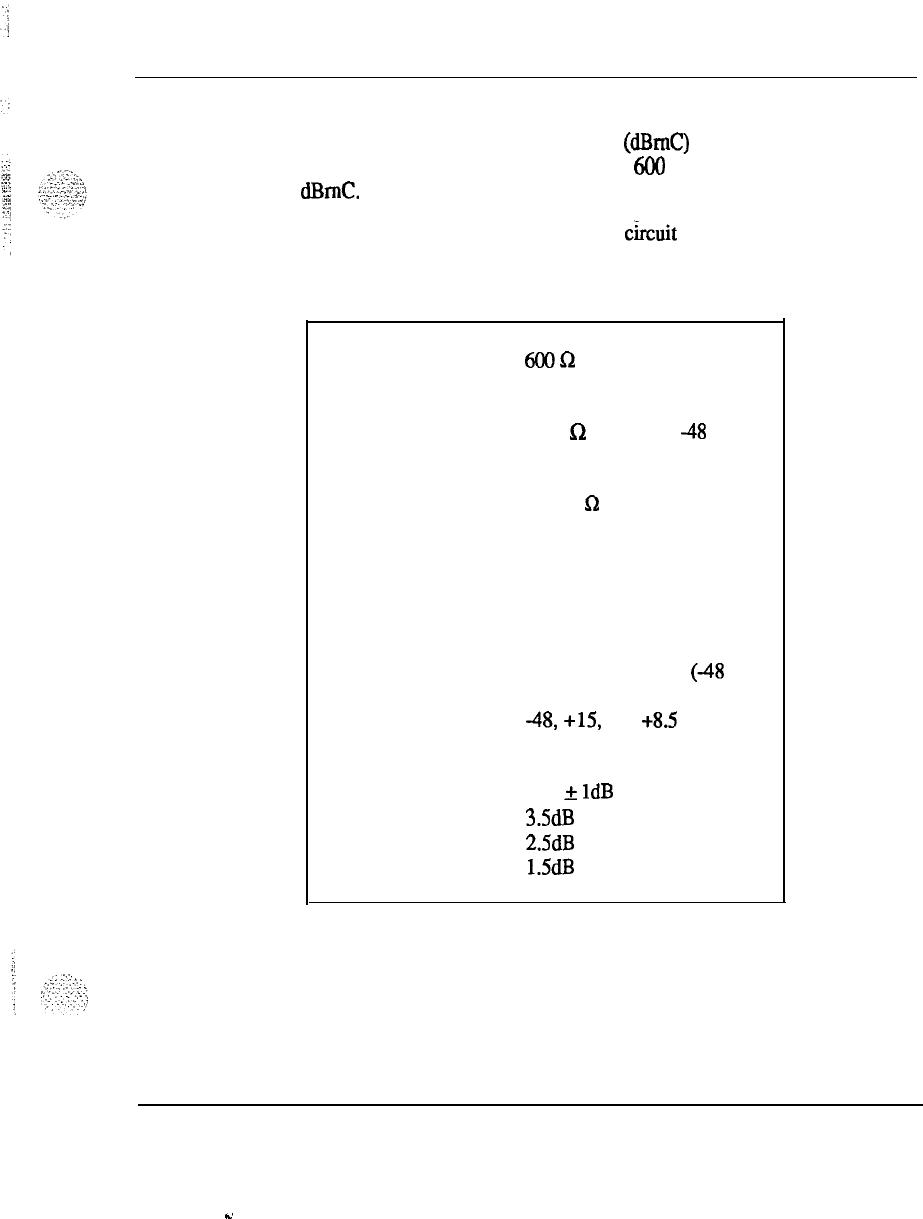
Summary 5
Message channel noise
The message channel noise C-weighted
(dBmC)
on 95% of the connections
(line to line) with both ends terminated in 600 ohms does not exceed 20
dBmC.
A technical summary of the Analog line
c&it
pack is’given in Table 3.
Table 3
Technical summary of Analog Line Card
Impedance:
600!2
Loop limit (excluding
set)
1000
a
at nominal
48
V
(excluding set)
Leakage resistance
30,000
sz
Ring trip
Ringing voltage
Signaling
Supervision
Power input from
shelf backplane
Insertion loss
Effective gain
During silent or ringing
intervals
86Vac
Loop start
Normal
battery conditions are
continuously applied
(48
V on
ring; ground on tip)
48,
+15, -15, +8.5 V and
ringing voltage; also -150 V on
Message Waiting Line card.
6dB
f
1dB at 1020 Hz
3SdB
loss for analog to F’CM,
2.5dB loss for PCM to analog
1.5dB at 1020 Hz
Analog line card description 553-3001-l 61
-.
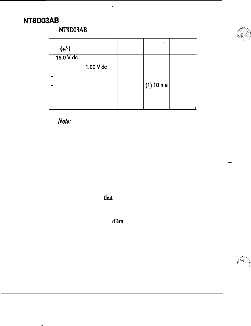
6 Summary
Power requirements
-
NT8D03AB
The
NlSDO3AB
Analog Line Card has the following power requirements:
1
Voltage Tolerance Idle
Active
-
Max
(+/-I
Current Current
+
150Vdc
0.50 V dc 48 ma Oma 48 ma
+ 8.5 Vdc
l.OOVdc
150 ma 8ma 280 ma
-
48.0 V dc 2.40 V dc 48 ma 40 ma 688 ma
-
48.0 V dc 2.40 V dc Oma
(1)lOma
320ma
86.0 V ac 5.00 V ac Oma (2) 10 ma 160 ma
-150.0 V dc 5.00 V dc 0 ma 2ma 32 ma
Note:
(1) Each active ringing relay requires 10 ma of battery voltage.
(2)
Reflects the current for ringing a single station set. There
may be as many as five ringers on each line.
Foreign and surge voltage protections
.-
When telephone lines connected to the line circuit are exposed to foreign
voltages by direct contact or induction (for example, power line crosses or
lightning), protection devices must be installed on the customer’s premises.
These devices must be capable of providing a path to ground from tip and
ring for foreign voltages that exceed 600 V peak.
Overload level
Signal levels exceeding + 7 dRm applied to the tip and ring cause distortion
in speech transmission.
.-
.._
.
.:
^
i:
‘_
,.-
.
.
:
;-.
‘.
.)
,*
Analog line card description 553-3001-l 61
.
.

:..
I
.-8..
-...
.
.
:1
-,_.-..-
.,
::
‘.-
.-
! ,,’
.
.
:
:.:

.-
SL-1 System
Options 21,51,61,71
Analog line card description
Copyright Q 1990 Northern Telecom
All rights reserved.
Information subject to change without notice.
Release 1 .O
Standard
January 29,199O
Printed in U.S.A.
n#
nartharn
tolocom
.J
I
I;
_
.I
_.,
_...
.
,.-..
,,
.,
.-.
,.
.
__
I-
,....
.
L:i
:.
I
,
.“,::
.I
:
.,.-y
.
I
‘.
_.:
..;
.
.
,.
_
;
:.‘T
:‘.
,’
.’
;
SL-1
System options
21,51,61,71
Digital line card description
Standard
Et
northorn
fdocom
Meridian1
..x
.:

.
.
.:
:.
.
..:.;
.1
.
.
_
.,
..:
:
,J
SL-1
System options
21,51,61,71
Digital line card description-
Publication number: 5533001-l 62
Document status: Standard
Document release: 1 .O
Date: January
29,199O
.
.
,..’
0
1990 Northern Telecom
All rights reserved.
Digital line card description 553-3001-l 62
ii
Revision history
Januaty29,1990
First issue of this document.
Digital line card description 553-3001-l 62
s.
:
About this document
iii
This practice outlines the characteristics, application, and operation of the
NTt3DO2AA Digital Line Card (Dgtl LC). The information is intended
tc
be
used as a guide when connecting customer-provided apparatus to the line
circuit. New naming conventions are applied to this release. The following
documents should be used as reference material:
References
See the SL-1 Planning
&
Engineering Guide
for
-
Muster Index
(553-3001~OGO)
-
System Overview
(553-3001-100)
-
System Engineering
(553-3001-151)
-
Spares Planning
(553-3001-153)
-
Equipment
Identijication
and
Ordering
(553-3001-154)
See the list of Line and Trunk Circuit Descriptions in the
Muster Index
(553-3001-000) for specific references to lines and trunks.
See the SL-1 Installation and Maintenance Guide
for
-
Circuit
PuckZnstuZlution
and Testing
(553-3001-211)
-
Fault
Cieuring
(553-3001-510)
-
Hurdware Replacement
(553-3001-520)
See the
SL-1 XI 1 Software
Guide for an overview of software architecture,
procedures for software installation and management, and a detailed
description of all Xl 1 features and services. This information is contained
in two documents:
Digital line card description
553-3001-l 62
., ._.
iv About this document
-
XII Software Management
(553-3001-300)
-
Xl1
Features and Services (553-3001-305)
See the SL-I XII Input/Output
Guide (553-300140) for a description of
all administration programs, maintenance
proms,
and system messages.
See
the
following Northern Telecom Publications for references to specific
telephone sets:
-
Meridian M2000 digital telephones: description, installation,
operation and maintenance
(553-2201-110)
-
Meridian M2317 digital telephone with alphanumeric display:
description , installation, operation, and maintenance
(553-2201-113
-
Meridian M3ooO touchphone: description, installation, operation and
maintenance
(553-2201-115)
-
Meridian modular telephones: description and specifications
(553-2201-l 16)
Digital line card description 553-3001-l 62
s.

V
Contents
General information
Requirements
1
1
Description
Meridian SL-1 data block
Physical
Functional
Configuration
Power supply to digital telephones
3
3
. .
3
4
4
4
Characteristics
-
5
Digital line card description
553-3001-l 62

vi Contents
Digital line card description 553-3001-l 62
General information
The NT8DO2AA Digital Line Card (Dgtl LC) is based on the design of the
QPC578 Integrated Services Digital Line Card. See 553-2201-193 for a
complete description of the QPC578. The Dgtl LC is a voice and data
communication link between the Meridian SL-1 switch and modular digital
telephones. When a digital telephone is equipped with the data option, an
asynchronous ASCII terminal or PC can be connected to SL-1 System
.-
through the digital telephone.
The Dgtl LC supports voice only or simultaneous voice and data service
over a single twisted pair of standard telephone wiring.
This publication describes the Dgtl LC. New naming conventions are
applied to this document. _-
For more information on modular digital telephones, see 553-2201-110 and
553-2201-l 11 for the M2000 series telephones, 553-2201-115 for the
M3000 telephone, and 553-2201- 113 for the M23 17 telephone.
Requirements
To use the Dgtl LC, the following SL- 1 requirements must be met:
-
Intelligent Peripheral Equipment (IPE) Modules must be used
-
Generic Xl 1, Release 15 software must be running
-
Superloops must be defined in the software
Digital line card description
553-3001-l 62
.
.
..:
:
:

2 General information
Digital line
card
description 553-3001-l 62
!
,’
_.:
.::.
:i
.I
.:
-:;;
:::
_.
_
c
_
.
,
5
T
7’;
:
_’
.-
3
Description
The NT8DO2AA Digital Line Card (Dgtl LC) is equipped with 16 identical
line circuits housed within an NTSD37AA Intelligent Peripheral Equipment
Module (IPE). Each line circuit provides a multiplexed voice, data, and
signaling path to and from digital apparatus over a a-wire full duplex 5 12
KHz
Time Compression Multiplexed
(KM)
digital link.
.
Meridian SL-1 data block
Each digital telephone and each associated data terminal is assigned a
separate Terminal Number (TN) in the SL-1 System data base.
Physical
Dgtl LC circuitry is contained on a 320 mm (12.5 in.) by 254 mm (10
ii%)
double-sided printed circuit board The pack connects to the backplane via
a 120-pin edge connector.
The faceplate of the Dgtl LC (7/S in. wide) snaps in place on the front of
the pack and is equipped with a red LED which lights only when the pack is
disabled. Upon power-up, the DgtI LC resets and the red LED will turn off
after the Dgtl LC is enabled. The card provides self-identification and fault
detection.
For information on the Mean Time Between Failure rate for the Dgtl LC,
see Spares Planning (553-3001-153).
Digital line card description
553-3001-l 62
.u
. .
.:
4 Description
Functional
The Dgtl LC contains an 8050 microprocessor that provides the following
functions:
-
card self-identification
-
self-test
-
control card operation
-
status report to the controller
-
diagnostics for maintenance purposes
Configuration
Up to 16 Dgd LC circuit packs can be mounted in one PE shelf if the
remaining slots are not used. In addition, up to 16 Dgtl LC packs can be
supported by a single NT8DO6AA Peripheral Equipment Power Supply (PE
Pwr Sup). The PE Pwr Sup is available for both ac and dc power.
._
Power supply to digital telephones
The Dgtl LC needs +15V dc over each loop at a maximum current of 80
mA. The line feed interface can supply power to one loop of varying length
up to 1067 m (3500 ft) using 24 AWG gauge wire with a maximum
allowable ac signal loss of 15.5
dB
at 256 KHz, and a maximum dc loop
--
resistance of 210 ohms.; 26 AWG gauge wire is limited to 745 m (2450 ft).
For a detailed description of the exact power requirements of each set type,
refer
to Meridian modular telephones
(553-2201-l 16)
Digital line card description 553-3001-l 62
..d
:
5
Characteristics
Table 1
Digital Llne Card circuit characteristics
Characteristics Description
Circuits per pack
Options
Impedance
Loop limits
16 voice, 16 data
Nil
1008
. .
100 ft (30 m) to 3000 ft (900 m) with
24 AWG PVC cable
kl5
VDC at 80
mA)l
0 to 3500 ft (1067 m) with 24 AWG
PVC cable
&15
VDC at 80 mA)]
Digital line card description 553-3001-l 62
.
.
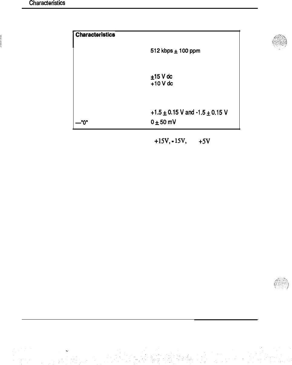
6
CharacterisGcs
Table 1 continued
Digital Line Card circuit characteristics
I
dharacteristlcs Description
Line rate
512kbps&lOOppm
Power supply
+ 5vdc
*15vdc
+lOVdc
Transmitter output voltage
-successive “1” bits
-“On
bits
+1.5&0.15Vand-1.5kO.15V
0*50mV
Note: The Dgtl LC requires
+lW,
-
lSV, and +5V from the
backplane.
Digital line card description 553-3001-l 62


.
.
SL-1
System options
21,51,61,71
Digital line card description
8
1990 Northern Telecom
All rights reserved.
Information subject to change without notice.
Release 1 .O
Standard
January 29, 1990
Printed in U.S.A.
r%t
northarn
talocom
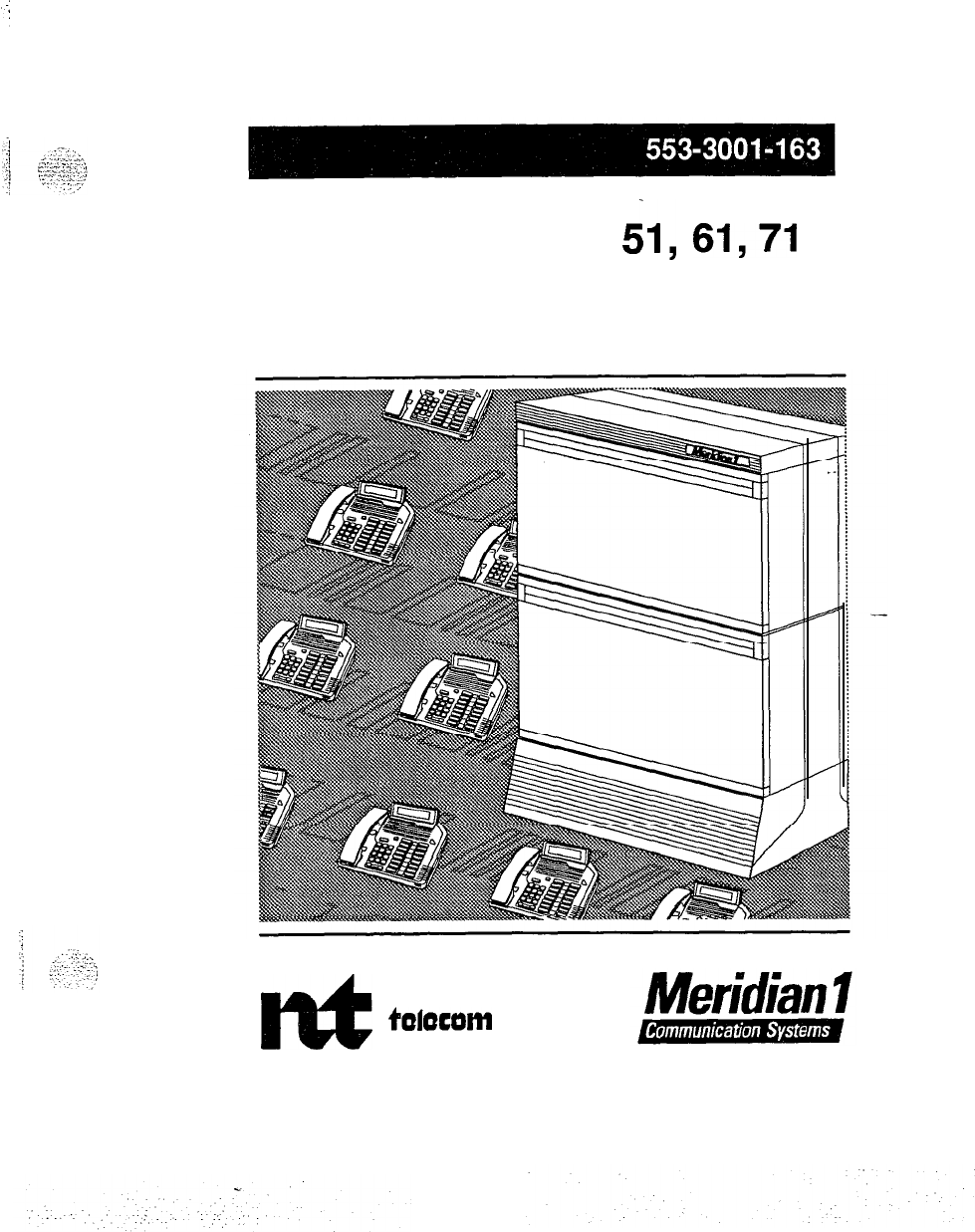
SL-1
System options 21,
&,
61,71
Analog message waiting line card description
Standard
Et
northern
tWocam

SL-1
System options
21,51,61,71
Analog message waiting line card description
Publication number: 553-3001-l 63
Document release: 1 .O
Document status: Standard
Date: January
29,199O
0
1990 Northern
Telecom
All
rights reserved.
Analog message waiting line card, description 553-3001-l 63
.
.’
:
.I.’
:
-.

ii
Revision history
January 29,199O
Standard, release 1.0
Analog message waiting line card description 553-3001-t 63
:,j
.‘,:;I’?
,-..
.,
. . .
.
-1
,...-
_....
,..-
.
.._
j
y
-::-
_.
1
:
::
:
:.
‘;
.,
iii
About this document
This practice outlines the characteristics, application, and operation of the
NTsDO9AB Analog Message Waiting Line Card. The information is
intended to be used as a guide when connecting customer-provided
apparatus to the line circuit. New naming conventions are applied to this
release. The following documents should be used as a reference:
References
See the SL-I planning
&
engineering guide
for
-
Masfer
index
(553-3001-000)
-
System overview
(553-3001-100)
-
System engineering
(553-3001-151)
-
Sparesplanning (553-3001-153)
-
Equipment identification and ordering
(553-3001-154)
See the list of line and trunk circuit descriptions in the
Master index
(553-3001-000) for specific references to lines and trunks.
See the SL-1 installation and maintenance guide
for
-
Circuit pack installation and testing
(553-3001-211)
-
Fault clearing (553-3001-510)
-
Hardware replacement
(553-3001-520)
--
See the
SL-I
XII
software guide
for an overview of software architecture,
procedures for software installation and management, and a detailed
description of all X 11 features and services. This information is contained
in two documents:
Analog message waiting line card description 553-3001-l 63
..d
iv About this document
-
Xl1
softwure management
(553-3001-300)
-
Xl1
features and services
(553-3001-305)
See the SL-1 XII input/output guide
(553-3001-400) for a description of all
administration programs, maintenance programs, and system messages.
See the following Northern Telecom Publications for references to specific
telephone sets:
-
Meridian M2lHO digital telephones: description, installation,
operation and maintenance
(553-2201-110)
-
Meridian M2317 digital telephone with alphanumeric display:
description , installation, operation, and maintenance
(553-2201-113
-
Meridian M3000 touchphone: description, installation, operation and
maintenance
(553-2201-l 15)
-
Meridian modular telephones: description and specifications ..
(553-2201-l 16)
Analog message waiting line card description
553-3001-l 63
.
..-.
:

V
Contents
General information
1
Application 3
Characteristics
Functional
5
. .
5
Technical summary
Analog line interface
Input impedance
Insertion loss
Frequency response
Message channel noise
Power requirements
Foreign and surge voltage protections
Overload level
--
7
7
7
7
7
8
9
9
9
Analog message waiting line card description 553-3001-l 63

vi Contents
Analog message waiting line card description 553-3001-l 63
.
.
.’
General information
1
This publication outlines the characteristics, application, and operation of
the Analog Message Waiting Line Card. The information is intended to be
used as a guide when connecting customer-provided apparatus to the line
circuit. The following Analog Message Waiting Line Card is available:
-
NT8DO9AB
-
Analog Message Waiting Line Card @-Law)
I.
The Analog Message Waiting Line Card provides talk battery and signaling
for regular 2-wire common battery 500~type (rotary dial), 2500-type
(DIGITONE dial) telephones and key telephone equipment.
Note:
DIGITONE is a trademark of Northern Telecom.
The NT8DO9AB Analog Message Waiting Line Card mounts in any
ofthe
16 slots in an NT8D37AA Intelligent Peripheral Equipment Module (IPE).
The 16 circuits connect with the switching system and with the external
apparatus via a
H-pin
connector at the rear of the pack. The pack is
320 mm (12.5 in) in height and 254 mm (10 in) in depth.
The circuits are connected to the shelf backplane and fed to the I/O panel
via I/O cables. From the I/O panel, the circuits are connected to the cross-
connect terminal via 25-pair cables. Connection to the station apparatus is
made at the cross-connecting terminal
Analog message waiting line card description 553-3001-l 63
.
.

2 General information
.-
.,
. .
.
e%.
.::\.
.
.-.
,_..
..,
i:
::
:
::y.,
:
..,..
:..;
Analog message waiting line card description 553-3001-l 63
C.
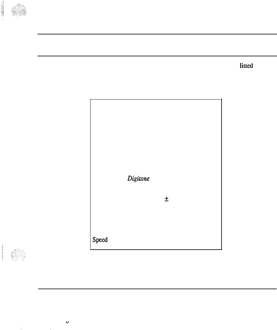
3
Application
The line card interfaces and is compatible with the equipment listed in
Table 1.
Table 1
Line card application and compatibility
Equipment Specifications
NE-500 type rotary dial
sets (or equivalent)
Dial Speed
8.0
to 12.5 pps
Percent Break
58
to 70%
Interdigital Time
240
ms
NE-2500 type Digitone sets
(or equivalent)
Frequency Accuracy
+
1.5%
Pulse Duration
40
ms
Interdigital Time
40
ms
Speed 12.5 digits/s
Analog message waiting line card description 553-3001-l 63
.
.
:
:

4 Application
Analog message waiting line card description 553-3001-l 63
.
Characteristics
5
Functional
The Analog Message Waiting Line Card contains a microprocessor that
provides the following functions:
-
card self-identification
-
self-test
-
control card operation
-
status report to the controller
-
diagnostics for maintenance purposes
--
The Analog Message Waiting Line Card also provides the following:
-
6OfIQ
balanced terminating impedance
-
analog-to-digital and digital-to-analog conversion of transmission and
reception signals for 16 audio phone lines
-
transmission and reception of SSD signalling messages over a DS30X
signalling channel in A10 format
-
detection of on-hook/off-hook status and switchhook flash
-
connection of 20 Hz ringing signal and automatic disconnection when
the station goes offbook
-
synchronization for connecting and disconnecting the ringing signal to
zero crossing of ringing voltage
-
loopback of SSD messages and PCM signals for diagnostic purposes
-
indication of board status with faceplate-mounted LED
Analog message waiting line card description 553-3001-l 63
.
.
:

6 Characteristics
-
correct initialization of all features at power-up
-
connection of -150 Vdc at 1 Hz to activate message waiting lamps
-
direct reporting of digit dialed (500 sets) by collecting dial pulses
-
detection of lamp status
-
disable/enable-selected circuits for maintenance
Analog message waiting line card description 553-3001-l 63
.
.
:..
:
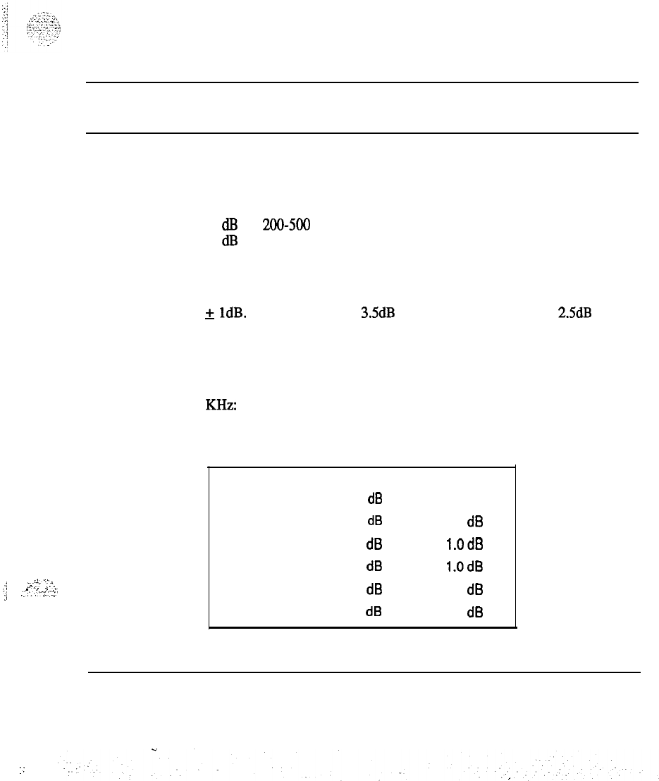
7
:
,....
.:
-...:-
_‘.
. .
.:
.
,
.,
._
I;
:
.:
.,:-
;.
r’::,
.:
Technical summary
Analog line interface
Input impedance
The impedance at tip and ring is 600 Ohm with a return loss of
20
dB
for
200-500
Hz
26
dl3
for 500-3400 Hz
Insertion loss
On a station line-to-line connection, the total insertion loss at 1 KHz is 6dB
+
1dB. This is arranged as
3SdB
loss for analog to PCM and 2.5dB loss for
PCM to analog.
Frequency response
The loss values in the table below are measured relative to the loss at 1
KHz:
Table 2
Frequency response
Frequency Minimum Maximum
60 Hz 20.0
dB
200 Hz 0.0
dB
5.0
dB
300 Hz -0.5
dB
l.OdB
3000 Hz -0.5
dB
l.OdB
3200 Hz -0.5
dB
1.5
dB
3400 Hz 0.0
dB
3.0
dB
Analog message waiting line card description 553-3001-l 63
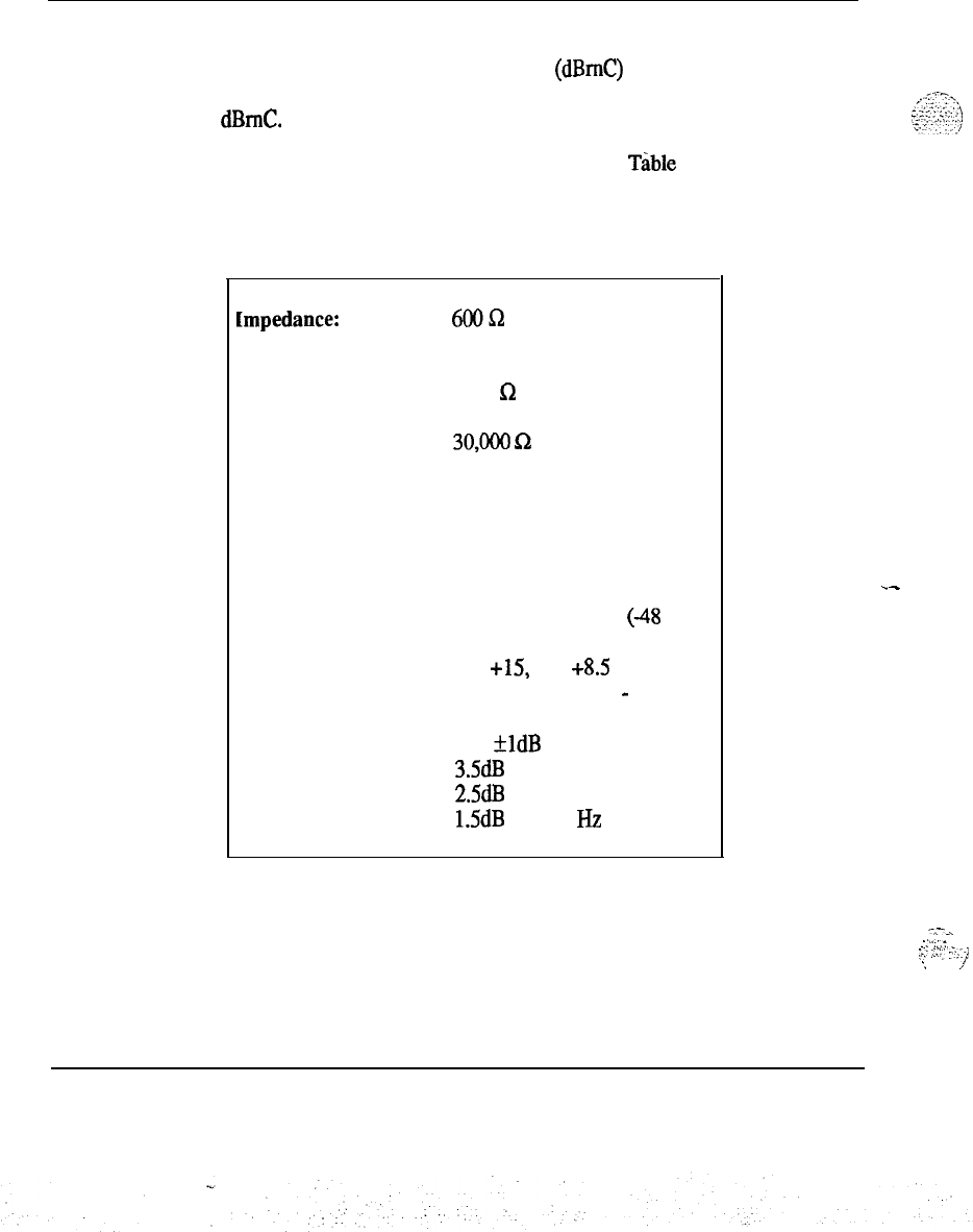
8 Technical summary
Message channel noise-
The message channel noise C-weighted (dBmC) on 95% of the connections
(line to line) with both ends terminated in 600 ohms does not exceed 20
dEImC.
A technical summary of the line card is given in
Tible
3.
Table 3
Technical summary of Analog Message Waiting
Line Card
impedance: 6oQsz
Loop limit (excluding
set)
1000
Sz
at nominal -48 V
Leakage resistance
Ring trip
Ringing voltage
Signaling
Supervision
Power input from
shelf backplane
Insertion loss
Effective gain
30,ooo Q
During silent or ringing
intervals
86Vac
Loop start
Normal battery conditions are
continuously applied
(48
V on
ring; ground on tip)
-48, +15, -15, +8.5 V and
ringing voltage; also
-
150 V on
Message Waiting Line card.
6dB
+ldB
at 1020 Hz
3.5dB
loss for analog to PCM,
2.5dB
loss for PCM to analog
1.5dB at 1020
Hz
.-
---...
.:-‘-::.:
i,’
._.,‘,’
-‘;.-1
:
J
Analog message waiting line card description 553-3001-l 63

Technical summarv 9
Power requirements
-
NT8DOSAB
The NT8DO9AR Analog Message Waiting Line Card has the following
power requirements:
Table 4
Power requirements
Voltage
(+/-I
+
12.0Vdc
+ 8.0 Vdc
-
48.0 Vdc
-
48.0 Vdc
88.0 V ac
-150.0 V dc
Tolerance Idle
Active
current current
0.36 V dc 48 ma Oma
8ma
40 ma
(1) 10 ma
(2) 10 ma
2ma
1
Max
48
ma
280 ma
688 ma
320 ma
160 ma
32 ma
Note:
(1) Each active ringing relay requires 10 ma of battery voltage.
(2)
Reflects the current for ringing a single station set. There
may be as many as five ringers on each line.
--
Foreign and surge voltage protections
When telephone lines connected to the line circuit are exposed to foreign
voltages by direct contact or induction (for example, power line crosses or
lightning), protection devices must be installed on the customer’s premises.
These devices must be capable of providing a path to ground from tip and
ring for foreign voltages that exceed 600 V peak.
Overload level
Signal levels exceeding + 7 dBm applied to the tip and ring cause distortion
in speech transmission.
Analog message waiting line card description 553-3001-l 63

SL-1
System options
21,51,61,71
Analog message waiting line card
description
Copyright
0
1990 Northern Telecom
All rights reserved.
Information subject to change without notice.
Release 1 .O
Standard
January 29,199O
Printed in U.S.A.
rEt
nartharn
talaccrm
C.
PRACTICE
553-2201-184
Issued: 84 01 20
Standard
IKTEGRATED
SERVICES NETWORK
MERIDIAN SL-1.
SL-1
LINE AND CONSOLE LINE PACKS
DESCRIPTION AND OPERATION
c
c
CONTENTS PAGE
1.
2.
3.
4.
5.
GENERAL
DESCRIPTION
Functions
.._
Physical Description
Interconnection with Shelf
Power Supply to Terminals
l-l
2-l
2-1
2-l
2-2
2-2
CIRCUIT CHARACTERISTICS 3-1
OPERATION WITH SL-1 SET
Idle Circuit States
Call Originated from an SL-1 Set
Call to SL-1 Set
Class-of -Service and Features
4-l
4-l
--4-l
4-2
4-6
DESIGN CONSIDERATIONS
Foreign and Surge Voltage Protection
Overload Level
5-l
5-1
5-l
Printed in
C.S.A.
@
Northern
T&corn
Limited 1993
Page i
1 Page
Revised,
05
06
.
.

r
.
.
--
PRACTICE 553-2201-184
1. GENERAL
1.01
This practice outlines the functions, interconnections, characteristics
and operation of the SL-1 Business Communications System, SL-1 Line
and Console Line circuit packs. The information is intended to be used
as a guide when designing or engineering the connection of apparatus to
the line circuit.
1.02 The information in this practice applies to the following packs:
l QPC451 SL-1 Line
(~-Law)
l
QPC520 SL-1 Line (A-Law)
l QPC518 Console Line
(~-Law)
(superce&d
by the
QPC451)
l
QPC519 Console Line (A-Law).
c
1.03 The four packs
use
identical circuit boards but are configured for
their respective operation. The SL-1 line packs can each interface to up
to eight SL-1 sets. The console line packs can interface to two attendant
consoles. The QPC451 SL-1 line pack can be used for four attendant-
consoles without console power or two attendant consoles with console
power.
.
cl
Page l-l
1 Page
Revised, 65 06
.
.

.-
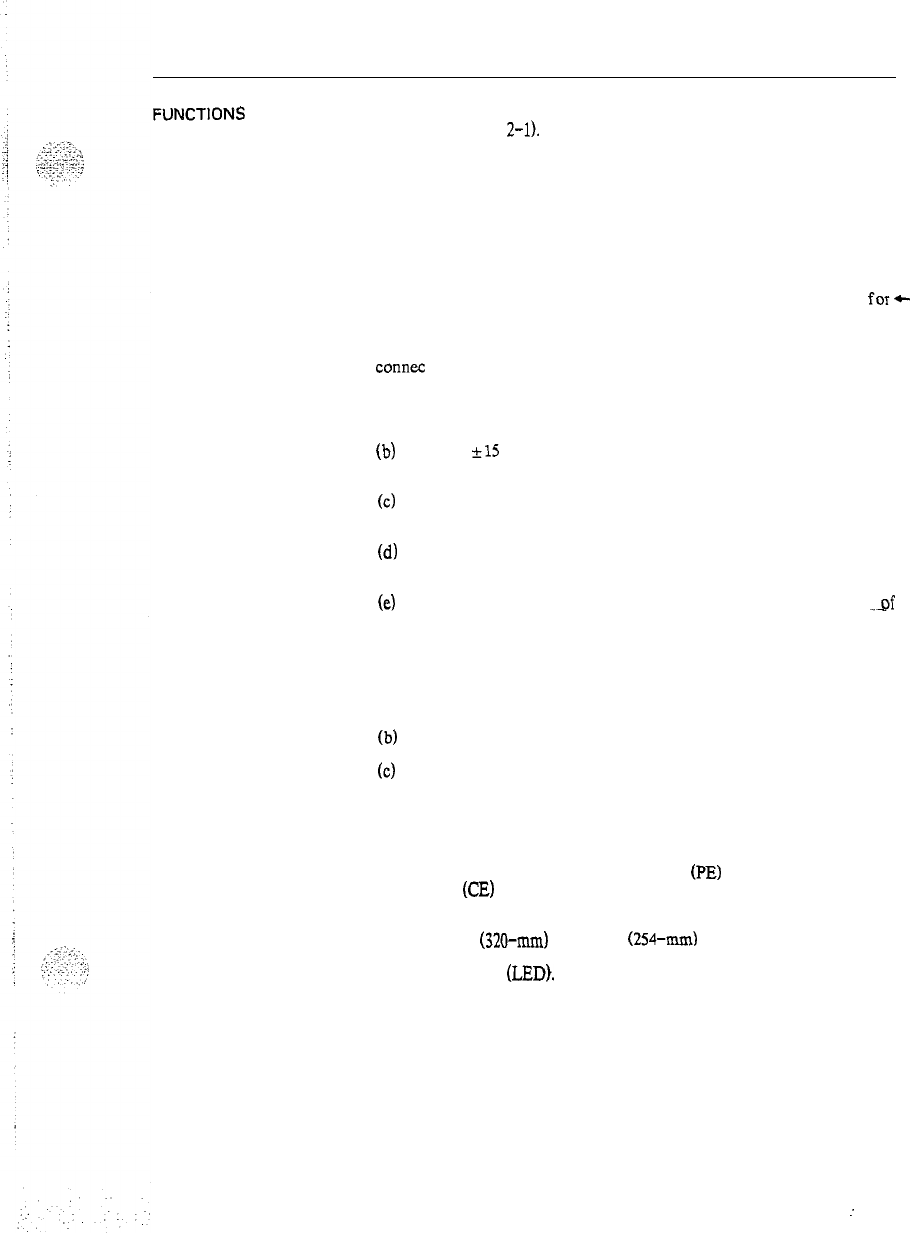
PRACTICE 553 -2201-184
2. DESCRIPTION
FUNCTlONS
2.01 The SL-1 and console line circuit packs each contain eight line
circuits (see Fig.
2-l).
The SL-1 line pack can use all eight circuits,
each circuit interfacing to an SL-1 set. The console line pack uses pairs
of line circuits to interface to attendant consoles: one pair may be used
from the upper four circuits and one pair from the lower four to
interface to two consoles.
Note: Line circuits on the SL-1 line pack are automatically
powered up during signaling and transmission. The connected
circuit pairs on the console line pack are continuously powered on.
2.02 For SL-1 set connections. one pair of wires is used
for+
transmission and a second pair for signaling (see Fig. 2-2). For
attendant console connections, two pairs of wires are used for
transmission connections and two pairs for signaling connections. These
connec Lions:
(a) terminate the loop tip and ring conductors with a balanced
600-ohm termination:
(b)
provide
~15
V power, phantomed over the transmission and
signaling pairs, to the set or console terminals:
(c)
provide a measure of isolation of foreign potentials on the loop
from portions of the transmission and signaling circuitry;
(d)
convert from the 2-wire transmission path of the loop to a 4-wire
transmission path:
(e)
provide analog-to-digital and digital-to-analog conversion
_qf
transmission signals.
2.03 The circuit pack includes two common multiplexing circuits to:
(a) interface the individual line circuits with the peripheral bus
signaling channel:
(b)
retime digital signals received from the peripheral bus;
(c)
decode address information received from the peripheral bus and
enable individual line circuits during selected time slots.
2.04 The information and signaling relevant to the SL-1 set or console
passes through the line circuit pack and is multiplexed with information
from other circuit packs. A multiplex loop connects the input and
output of up to two Peripheral Equipment
(PE)
shelves to the Common
Equipment
(CE)
where switching takes place (see Fig. 2-2 and 2-3).
PHYSICAL 2.05 The line circuits and common circuitry of the pack are mounted
DESCRIPTION on a 12.5 in
(320-mm)
by 10 in
(254-n&
printed circuit board. The
front of the pack is equipped with two pack extractors and a Light
Emitting Diode
(LED).
The rear of the pack is equipped with a
connector capable of accepting 80 pins. Ten of these circuit packs may
be mounted in one PE shelf but not to exceed 50% of the packs in a
cabinet.
Page 2-l
3 Pages
Revised, 85 06
:
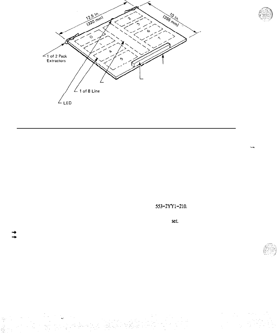
PRACTICE 553-2201-184
I- Printed
Circuit Board
L
Common
Circuitry
Connector With 2 Rows of
40 Pins Each for Shelf
Connections
Circuits
Fig. 2-l
Identification of the Circuits on the Board
INTERCONNECTION
WITH SHELF 2.06 The IO-pin connector on the rear of the circuit pack connects to
an 80-line bus system at the rear of the PE shelf. The bus lines feed
into eight multi-pin connectors. Seven of these connectors link the line
circuits to the corresponding terminal equipment and one feeds power
to the PE shelf from the power converter shelf.
.-
2.07 Thirty-two of the 80 pins per circuit pack are connected to
terminal equipment, 2 pins provide ground, 13 pins interface with the
CE via the peripheral buffer and 15 pins provide voltages to the circuit
pack.
2.08 For detailed information on terminal set line connections to the
four PE shelf connectors, refer to
553-2Wl-210.
POWER SUPPLY TO
TERMINALS
+
-9
2.09 The SL-1 set battery supply is -30 V dc phantomed over the
audio and signaling leads to each terminal
set.
2.10 As a general installation guideline. sufficient power is available for
the SL-1 set at a normal operating range of 189 ohms (see Loop Limits
in Table 3-A).
Page 2-2
Revised, 85 06
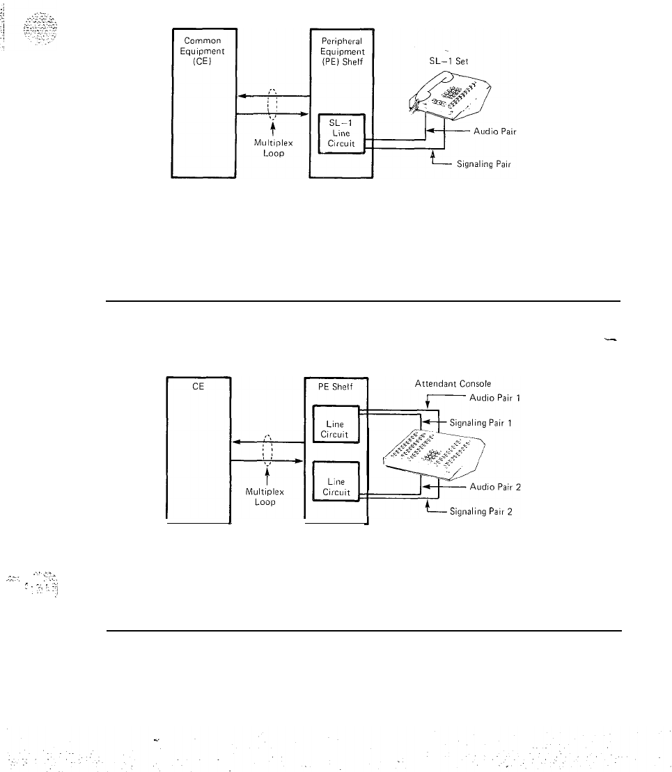
PRACTICE 553-2201-184
Fig. 2-2
Line Circuit Connection to SL-1 Set
-
I
I
I
J
..:..-..
:-..I,
~
:
~
:_
I:i
,f
Fig. 2-3
Line Circuit Connection to Attendant Console
Page 2-3

--
.
.
:
PRACTICE 553-2201-184
3. CIRCUIT CHARACTERISTICS
_
3.01 The circuit characteristics of the line pack are listed in Table 3-A.
Table 3-A
CIRCUIT CHARACTERISTICS OF THE LINE PACK
SIGNALING PAIR
Mode
Rate
Level
AUDIO PAIR
Mode
CHARACTERISTICS
CIRCUITS PER PACK
OPTIONS
IMPEDANCE
Voice Pair
Signaling Pair
NOMINAL INSERTION LOSS
LOOP LIMITS
AS RELATED TO THE CIRCUIT PACK
Eight individual circuits
Nil
600 ohms
600 ohms
5
dB
line-to-line
WIRE DISTANCE
GAUGE
22
6000 feet
(1830
m)
24
3700 feet
(1150
m)
26
2300 feet (675 m)
--
Note: Under certain conditions the loop limits may be
extended to 8000 feet (2450
m).
See
553-2YYl-210.
+
Diphase
2.37K
bit/s
0.75
kO.05
V peak-to-peak across the line.
Analog (audio)
Page 3-1
Revised, 85 06

PRACTICE 553-2201-184
Table 3-A Continued
CIRCUIT CHARACTERISTICS OF THE LINE
PACK-
CHARACTERISTICS AS RELATED TO THE CIRCUIT PACK
PHANTOMED POWER
30
+l
V divided as:
Audio Pair Level
+15
kO.05
v
Signaling Pair Level -15
*0.05
v
POWER INPUT FROM SHELF
f6,
-6,
+2.5
V,
BACKPLANE 30 V dc balanced
_....
_^,
5
‘,_
-1
.’
‘,
Page 3-2
Reissued, 85 06
.
.

PRACTICE
553-2201-184
4. OPERATION WITH
SL-1
SET
CALL ORIGINATED
FROM AN SL-1 SET
I
/
.
.
_
,
-:
I
.
.
7.’
..!,
,_.,..-,..
:
IDLE CIRCUIT STATES 4.01
SL-1
Set On-Hook. Multiplex control generates and sends scan
message to SL-1 set (2.5 ms message every 10 ms). Message is sent via
the signaling pair and hybrid transformer (Fig. 4-l).
(1) Message detected by Scan and Signal Distributor
@SD).
(See Fig.
4-2 and 4-3.)
(2)
No message is being sent to line circuit on signaling pair.
(3) In time slot 0, CE scans each line circuit on loop in sequence,
detecting any change in signaling on the data input bus.
(4) Line circuit 0 is enabled in time slot 0. Signaling on data output
bus indicates that CE is ready to receive data.
(5)
No message on data input bus to CE indicates line circuit 0 is idle.
4.02 Originating the Call. SL-1 is off-hook (key operated). Off-hook
is detected by SSD in SL-1 set.
(1)
SSD sends off-hook signaling to line circuit on signaling pair at
2.37K
bit/s when scanned by message from multiplex. control.
(2)
Off-hook message from line circuit 0 is multiplexed with messages
from other line circuits and sent at a rate of 64K bit/s to the CE.
(3)
(4)
(5)
CE line scan detects change in signaling for line circuit 0.
CE line scan stops.
For the next 31 times, time slot 0 signaling message is sent-to CE
on data input bus from line circuit 0, then line scan continues.
(6)
CE detects signaling from line circuit 0 and determines circuit
number (TN number).
(7)
(8)
CE assigns message time slot to line circuit from time slots 2
through 31.
Signaling from CE is applied to the SL-1 set or console on
signaling pair. Rate is changed from 64K bit/s to
2.37K
bit/s by
multiplex control.
(9)
Signaling is detected by SSD.
(10) SL-1 set directory number lamp is lit.
(11) PCM codec is enabled during message time slot assigned by CF.
(12)
Dial tone on the data output bus is applied to SL-1 set via
multiplex control, PCM
codec,
digital-to-analog filter, hybrid
transformer and audio pair (during message time slot).
(13)
Dialed information from SL-1 set on signaling pair is applied to
the data input bus during time slot 0 (signaling).
Page 4-l
6
Pages
PRACTICE
553-2201-184
CALL TO
SL-I
SET
Page 4-2
(14)
CE detects dialing and removes dial tone at start of dialing.
(15) CE encodes dialed information.
(16) Ringback
tone on the dam output bus is applied to SL-1 set over
audio pair during message time slot assigned by CE (busy tone
received if called number is busy).
4.03 Talking Connection. Called number answers.
(1)
(2)
(3)
Ringback tone is removed by CE.
Digital voice on dam output bus is applied to SL-1 set via
multiplex control, PCM codec, digital-to-analog filter, hybrid
transformer and audio pair during message time slot.
Analog voice on audio pair from SL-1 set is applied to dam input
bus via hybrid transformer, analog-to-digital filter, PCM codec,
multiplex control, and buffer (during time slot).
4.04 Terminating the Call. Assume SL-1 set goes on-hook first.
(11
On-hook message is transmitted from set to line circuit.
(2)
Signaling on data output bus changes: SL-1 set lamp extinguishes.
.-
(3)
ADD inputs removed (no signaling for line circuit
01.
(4)
Line circuit enable inputs are removed (message time slot is no
longer assigned to line circuit).
(5)
Circuitry in IDLE condition, ready for next call.
4.05 Signaling to the
TerminaLIn
time slot 0, CE scans
each
line on
the
(1)
(21
loop-in sequence.
CE has call for line circuit 0.
CE determines line circuit 0 is idle (no signaling from circuit on
data input bus during time slot
01.
(31
(41
(5)
(6)
(7)
(8)
(9)
CE assigns message time slot for audible signaling (from time slots
1 through
31).
Line circuit is enabled during time slot 0.
Visual signaling data on data output bus during time slot 0 is
applied to multiplex control. Visual signaling data is applied to
SL-1 set over signaling pair.
Signaling is detected by SSD (Line lamp of SL-1 set flashes).
PCM codec is enabled during message time slot.
Audible signaling applied to SL-1 set via digital-to-analog filter,
hybrid transformer and audio pair.
SL-1 set signaled audibly (tone ringing).
I-
::;-:,
:
‘.
:.j
.
.
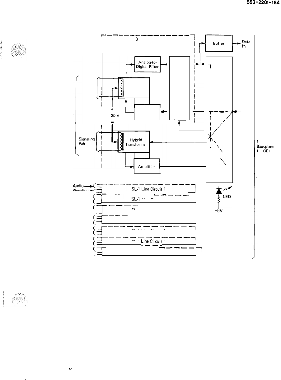
PRACTICE
553-2201-184
SL-1
Terminal
set
---------------
I SL-1 Line Circuit
II
1
d-ky
Audio
Pair
Hybrid
Transformer
I
I
j,”
Digital-to-
-
Analog Filter
I
-
Codec
[Codec 1
Enable 1
l
L--------------J
Audio--t(=r----SL-,LineCiCcuit,----l
Signaling*
a
-------------
_1
(=I---------
-----
(
1
ll
SL-1
Line Circuit 2
c=r----
---A---
(
--I
1
SL-1 Line Circuit 3
(----
---------
c
+
SL-1 Line Circuit 4
1
(=r-----------l
(1
SL-1 Line Circuit 5,
(=T----
-------~
(1
,SL-1
LineCircuit
6
CT
------
----_
~
cq
SL-1 Line Circuit 7,
Multiplex
-,
Control
I
r-
_
-,-
Data
/’
out
I
1’
<’
I
’
1
‘\
\
’
‘\-
Card
_I
Enable
+6V
‘E Shelf
3%kplane
to
CE)
--
Fig. 4-l
Simplified Functional Block Diagram of Line Circuit Pack
Page 4-3
-.
:.
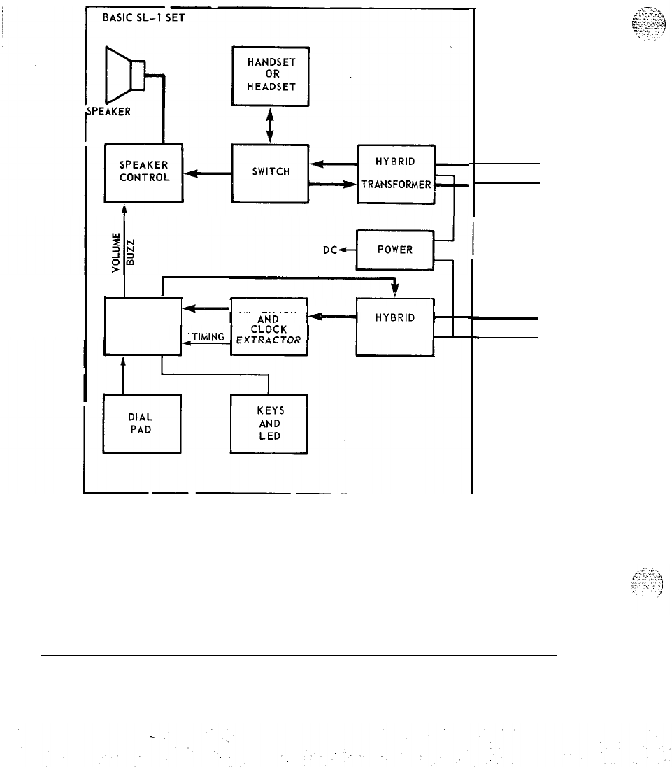
PRACTICE 553-2201-184
I
-
AMPLIFIER
SSD TRANSFORMER .
AUDIO PAIR
SIGNALING
PAIR
2.37 Kbps
Fig. 4-2
SL-1 Line Circuit Connected to Basic SL-1 Set
Page 4-4
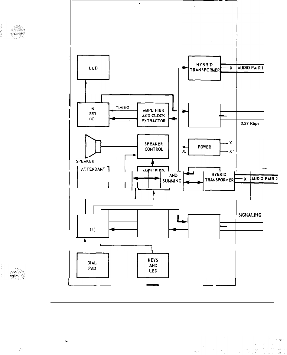
PRACTICE 553-2201-184
BASIC ATTENDANT CONSOLE
-
,
LED
n
SPEAlER
1
ATTENDANT
1
I
I
HANDSET
!
1
HEADSET
1
(
, OR
f++j
;U$;;
q
TR:ki%MERt”“‘“‘““I
1
1
NETWORK I‘
, VOLUME, BUZZ
1
‘-f-
SIGNALING
+
HYBRID PAIR 1
TRANSFORMER
-
X’
2.37.Kbps
CONTROL
I .
1ClCLIAI
IUI-
ATIMING AMPLIFIER ,
.JI”I.-LII.v
HYBRID PAIR 2
SSD
AND
(4)
4
CLOCK
.=
TRANSFORMER
-
X’
I
-
EXTRACTOR 2.37 Kbps
4
i I
I
I
I-
-
--A
Fig. 4-3
Console Line Circuit Connected to Basic Attendant Console
.
.
..:
Page 4-5
PRACTICE 553-2201-184
4.06 Terminal Answers. SSD in SL-1 set sends off-hook signaling to
line
(1)
(2)
(3)
(4)
(5)
circuit on signaling pair.
Off-hook signaling data on data input bus during time slot
0
(via
multiplex control and buffer).
CE detects signaling.
CE changes visual signaling on data output bus during time slot 0.
Visual signaling is applied to
SL-1
set on signaling pair. Line lamp
of SL-1 set changes from flashing to steady light,
CE removes audible signaling from data output bus during message
time
slot (message time slot now assigned for voice
communications).
Audible signaling at SL-1 set stops.
4.07 Talking Connection. PCM codec is enabled during message time
slot.
(1) Digital voice on data output bus is applied to SL-1 set via
multiplex control, PCM codec, digital-to-analog filter, hybrid
._
transformer, and audio pair.
(2)
Analog voice from SL-1 set is applied to data input bus via audio
pair, hybrid transformer, analog-to-digital filter, PCM codec,
multiplex control, and buffer.
4.08 Terminating the Call. Assume SL-1 is put on-hook first.
(1)
SSD transmits on-hook message to line circuit.
(2) On-hook message transmitted to CE through data input bus during
time slot 0 at a rate of 64K bit/s.
(3)
CE detects a change in signaling.
(4) Signaling on data output bus changes; SL-1 set line lamp
extinguishes.
(5)
ADD inputs are removed (no signaling for line circuit 0).
(6)
Enable inputs are removed (message time slot no longer is assigned
to line circuit
0).
CLASS-OF-SERVICE
AND FEATURES
(7)
Circuitry in IDLE condition: ready for next call.
4.09 All calls originating from and terminating on stations connected to
line and trunk circuits may be controlled with or without attendant
assistance. Call restrictions to the exchange network and special services,
are assigned through unique station/line circuit data blocks contained in
the system memory. Similarly, feature assignments are arranged through
the same data blocks. Refer to
553-2YYl-105
for a complete list and
description of features and services. Refer to
553-2YYl-310
for a
description of how features and services are created in the system
memory.
Page 4-6
-

PRACTICE
553-2201-184
5. DESIGN CONSIDERATIONS
FOREIGN AND SURGE
VOLTAGE PROTECTION 5.01 When telephone lines connected to the line circuit are exposed to
foreign voltages by direct contact or induction (e.g., power line crosses
or lightning), protection devices must be installed on the customer’s
premises. These devices must be capable of providing a path to ground
from tip to ring for foreign
voltages
that exceed 600 V peak.
OVERLOAD LEVEL 5.02 Signal levels exceeding
+7
dBm
applied to the tip and ring will
cause distortion in the system.
Page 5-1
1 Page

.
::
‘.
rut
northern
tukcom
PRACTICE 553-2201-183
Issued: 88 08 10
Standard
INTEGRATED SERVICES NETWORK
MERIDIAN
SL-i.
500/2500
LINE PACKS
DESCRIPTION AND OPERATION
CONTENTS
PAGE
1.
GENERAL . . . . . . . . . . . . . . . . . . . . . . . . . . . . . . . . . .
.._.....
1-1
2.
DESCRIPTION
2-1
3.
APPLICATION 3-1
4.
CHARACTERISTICS 4-1
Functional
..,.,....._..,,
,,.
_.,.
4-1
Technical Summary 4-3
Limitations 4-4
Power Requirements 4-4
Environmental
4-6
Foreign and Surge Voltage Protection 4-6
Overload Level 4-6
5.
OPERATION 5-1
Idle Circuit State 5-l
Call Originated from a
500/2500
Telephone
5-1
Call to Telephone 5-2
Message Waiting Lamp Operation 5-3
Ground Button Operation 5-4
Class of Service and Features 5-5
Reason for Reissue: This practice is reissued to include
information related to the QPC789
16-Port
Message Waiting
c
500/2500
Line circuit pack. Changes are indicated by margin arrows.
c
Prlnred
I”
LISA
’
Northern
T&corn
1983
Page i
1 Page

.
PRACTICE 553-2201-183
1. GENERAL
1.01
This practice outlines the characteristics, application and operation
of the
500/2500
line circuit packs. The information is intended to be
used as a guide when connecting customer-provided apparatus to the
line circuit.
1.02 The following
500/2500
line packs are availadle:
. QPC192
-
Off-Premise Extension
(OPX)
Line pack
(+a~)
l QPC292
-
Off-Premise Extension
(OPX)
Line pack (A-Law)
l
QPC452
-
Basic
500/2500
Line pack for
~-Law
applications
l
QPC494
.-
Message Waiting Line pack (~-Law)
l QPC521
-
Basic
500/2500
Line pack for A-Law applications
l QPC532
-
Ground Button Recall Line pack (A-Law and
~-Law)
l
QPC558
-
Message Waiting Line pack (A-Law)
l QPC594
-
16-Port
Basic
500/2500
Line pack
(+a~)
l QPC681
-
Parallel Message Waiting Line pack
(~-Law)
l
QPC682
-
Parallel Message Waiting Line pack (A-Law).
l QPC729
-
16-Port Basic
500/2500
Line pack (A-Law)
l QPC789
-
16-Port
Message Waiting
500/2500
Line pack
(+a~)-
+
Page l-l
1
Page

--
PRACTICE 553-2201-183
2. DESCRIPTION
2.01 All versions of the
500/2500
line packs provide talk battery and
signaling for regular 2-wire common battery
SOO-type
(rotary dial),
2500-type
(DIGITONE*
dial) telephones and key telephone equipment.
The various special versions serve additional purposes as described in
Part 4.
2.02 The line circuit packs mount in a Peripheral Equipment
(PE)
shelf.
The circuits connect with the switching system and with the external
apparatus via an 80-pin connector at the rear of the pack. The pack is
318 mm (12.5 in) in height and 254 mm
(10
in) in depth.
2.03 The 80-pin connector plugs into an IO-line bus system on the back
of the PE shelf. These 80 bus lines feed into seven multi-pin
connectors. Seven connectors link the line circuits to the cross-connect
terminal;
ttio
faceplate connectors on the Peripheral Buffer link the PE
shelves to each other and to the Common Equipment
(CE);
and one
connector feeds power to the PE from the converter shelf.
2.04 Connection to the station apparatus is made at the
cross-connecting terminal, as shown in the following block diagram of
the line circuit connected to a
500/2500
telephone:
.-
:’ .
.
.._.
.
. .
..I
..;
:
:
.\:-
.
*
DIGITONE
is
a trademark of
Norlhern
Telecom
Page 2-l
1 Page
.
.
.,:

PRACTICE 553-2201-183
3. APPLICATION
3.01 The line circuit interfaces and is compatible with the equipment
listed in Table 3-A.
Table 3-A
LINE CIRCUIT APPLICATION AND COMPATIBILITY
EQUIPMENT SPECIFICATIONS
NE-500 TYPE ROTARY DIAL
SETS (or equivalent)
Dial Speed
Percent Break
Interdigital Time
NE-2500 TYPE DIGITONE
SETS (or equivalent)
Frequency Accuracy
Pulse Duration
Interdigital Time
Speed
KEY TELEPHONE
EQUIPMENT
RECORDED
ANNOUNCEMENT
DIAL LONG LINE CIRCUIT
LOOP EXTENDERS
24V4 REPEATERS
8.0 to 12.0 pps
58 to 69%
240 ms
k1.5
%
40 ms
40 ms
12.5 digits/s
NE-lA1,
NE-lA2,
oi-
equivalent
*CODE-A-PHONE 200
VCA RDY
(unattended telephone
answering set)
J99234T-2/SD96555-01
Various
598615
AJ-l/SD97747-01
598615
BJ-l/SD97747-01
* CODE-A-PHONE is
a
trademark of Ford
Induwier
Inc
Page 3-l
1 Page

--
.i
:
:
.
.
PRACTICE 553-2201-183
4. CHARACTERISTICS
FUNCTIONAL
Common Features
4.01
The following features are provided:
l
6000
balanced terminating impedance
Unique Features
.A.::
.
._
.:
:.
::.::.:.,
l -48 V through a battery feed resistance and ground
l supervise the loop current to determine on-hook/off-hook status
l ringing current to the loop
l isolation of foreign potentials on the loop from the transmission and
signaling circuit
l conversion from a
2-
to a 4-wire transmission path
l analog-to-digital and digital-to-analog conversion of transmission
signals
l common multiplexing’ circuit to interface with the peripheral bus
signaling channel .
l retime the digital signals received from the peripheral bus
l decode address information received from the peripheral bus to
enable individual line circuits during selected time slots
l control the disconnection timing of ringing current to the loops to
avoid switching during current peaks.
--
4.02 The various special versions of the
500/2500
line pack have
additional features as follows:
4.03
QPCl92
and QPC292 OPX Line packs:
l serve lines up to a maximum loop resistance of 1400
R
l
serve Dataphone sets
l have line-to-line insertion loss of 1
dB.
4.04 QPC494 and QPC558 Message Waiting Line packs:
l provides connection of -150 V in a steady or 1 Hz flash rate to
activate the Message Waiting lamp on the telephone
l provides for one Message Waiting lamp per line
l maintain all Message Waiting lamps off and do not allow phones to
ring during power-up sequence.
Page 4-l
8 Pages
.
.
PRACTICE
553-2201183
Page 4-2
.
l generate diagnostics ‘an “ERROR
500”
message when the Message
Waiting lamp is defective or the telephone is unplugged provided
-150 V is present. If -150 V is missing (blown fuse) no message is
generated under any condition.
4.05 QPC681 and QPC682 Parallel Message Waiting Line packs:
l provides the same features as the
QPC494‘
and
QPCS58
Message
Waiting Line packs
l provides a -48 V connection to a lamp bank.
4.06 QPC532 Ground Button Recall Line pack:
l provides detection of ground on tip or ring with
40
ms validation
time
l strap-selectable A-Law or
~-Law
coding
l strap-selectable 0, 1, 2 or 4
dB
pad in each transmission path
l
impedance-matching to 3-component complex impedances
l
trans hybrid balance against 3-component complex impedances.
4.07
RPC584
and QPC729
16-Port
Basic 50012500 Line Packs:
l sixteen individual line circuits per pack.
4.08
QPC789
16-Port
Message Waiting 50012500 Line Pack:
l
sixteen message waiting individual line circuits per pack.
-
,:
;
;-
.A’
*.
r
-1
<,.?.
.j
,,
‘;,.->:
‘,I.
.:
‘,,
.:.
..’
.’

PRACTICE 553-2201-183
TECHNICAL SUMMARY 4.09 A technical summary of the line circuit pack is given in Table
4-A.
Table 4-A
TECHNICAL SUMMARY OF LINE CIRCUIT PACK
Impedance:
QPC452/521,
QPC494/558
QPC594/129/189,
QPC681/682
QPC192/292
QPC532
600 R
600 R
900
n
600 R, matches 3-component complex
impedances
+
Loop Limit (excluding set):
QPC192/292
All others
1400
R
at nominal -48 V
1000
R
at nominal -48 V
Leakage Resistance
QPC532
All others
Ring Trip
Ringing Voltage
Signaling
Supervision
Power input from shelf backplane
Insertion loss
Effective Gain
(QPC192/292)
20,000 R
30,000 R
During silent or ringing intervals
Determined by the type of ringing generator
provided in the system
Loop start
Normal battery conditions are continuously
applied
(-48
V on ring: ground on tip) --
-52, -48, i-6, -6, i-2.5 V and ringing voltage:
also -150 V on Message Waiting Line cards.
5,
+1
dB,
at 1020 Hz
1.5 dB at 1020 Hz
Page 4-3
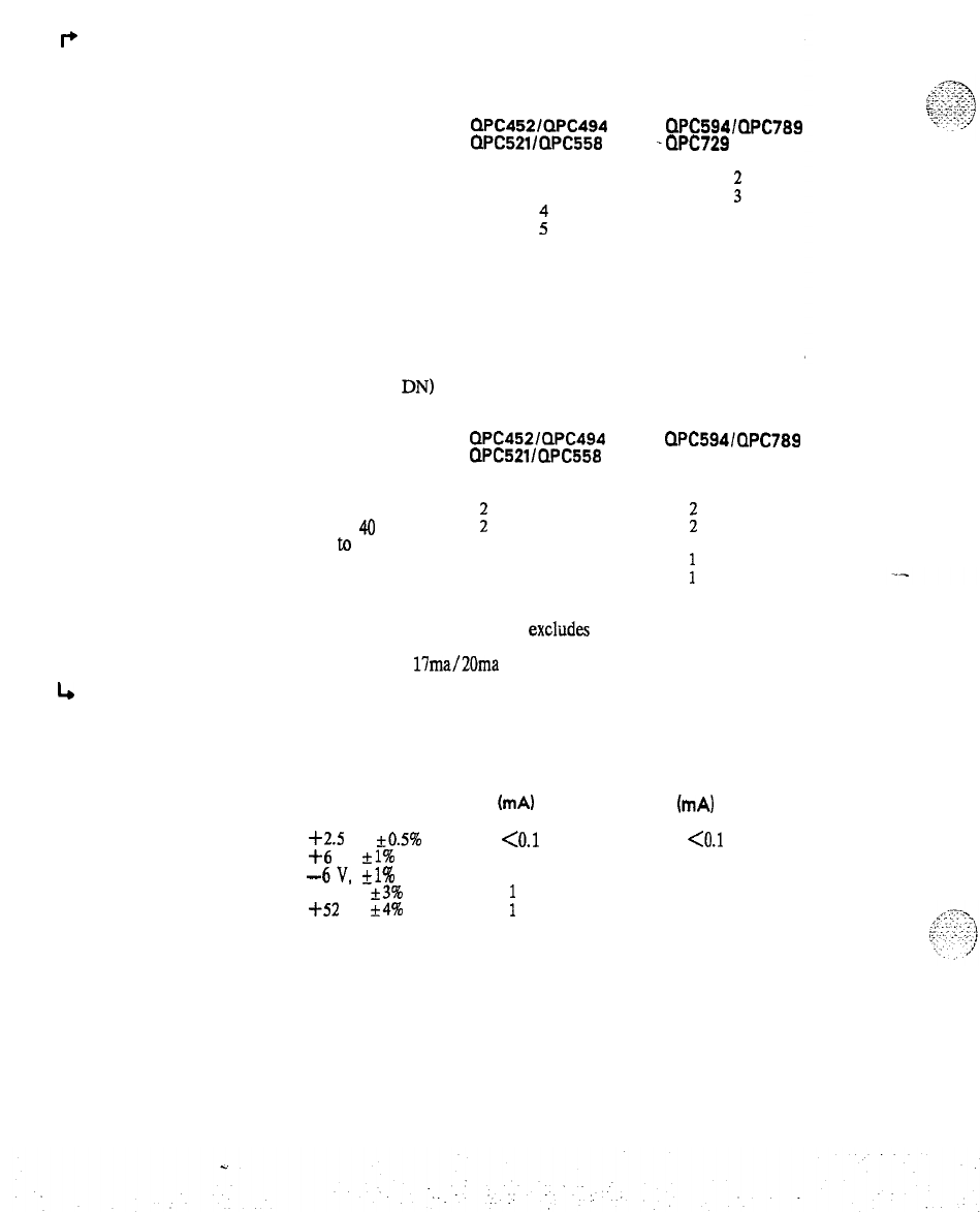
PRACTICE 553-2201-183
p
LIMITATIONS
4
POWER
REQUIREMENTS
Page 4-4
4.10 The maximum number of Ringers that can be connected to
DN loop is shown below:
MAXIMUM NUMBER OF RINGERS
LOOP
QPC452lQPC494 QPC594/QPC789
RESISTANCE
QPC521/QPC558 -QPC729
1000
2
850
3
i
600
i
4
350
4
Note:
Loop resistance excludes impedance of telephone sets.
4.11
Supervision limitations are given in Table 4-B.
4.12 To maintain transmission quality, the following shows
each
the
. .
maximum number of Voice Calls (number of telephone sets off-nook
on the same
DN)
recommended:
QPC452lQPC494 QPC5941QPC789
QPC521/QPC558
QPC729
RESISTANCE
(OHMS)
17ma
20ma
17ma
20ma
up to
40 21
41
to
100
;
1
;
1
101
to
250 2
1
1
251
to
1000
11
:
1
Note 1:
Loop resistance exclttdes impedance of telephone sets.
Note 2:
17ma/20ma
is the current that a typical telephone set
requires in an off-hook condition.
4.13 The QPC452, QPC521, QPC681 and QPC682 packs have the
following typical power requirements:
VOLTAGE IDLE CURRENT ACTIVE CURRENT
ImA) (mA)
+2.5
V,
*00.5%
<O.l <O.l
+6
V,
kl%
50
140
-6V,
+l%
50 140
-48 V,
f3%
320
-f-52
V,
+4%
:
85
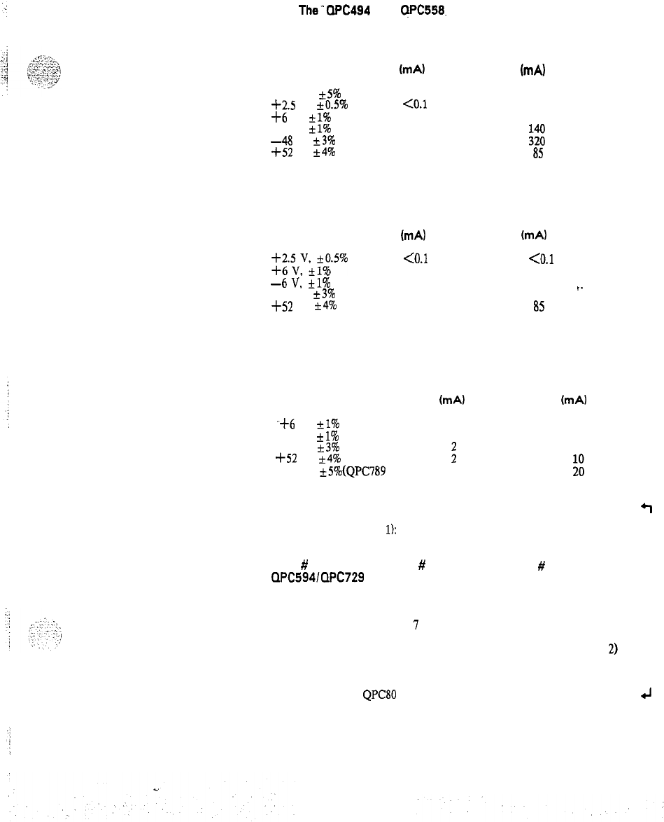
PRACTICE 553-2201-183
4.14
The-WC494
and
QPC558.
packs have the following typical
power requirements:
VOLTAGE
-150 v,
+5%
+2.5
V,
+0.5%
+6
V,
+l%
-6 V,
+l%
-48
v,
+3%
+52
V,
+4%
IDLE CURRENT
(mA)
0
<O.l
50
50
1
1
ACTIVE CURRENT
(mA)
30
co.1
140
~~
a5
4.15 The QPC532 pack has the following typical power requirements:
VOLTAGE IDLE CURRENT ACTIVE CURRENT
(mA) (mA)
$“vv$I.5%
<O.l <O.l
,
0
50 150
-6V,
kl%
50
150
-48 V,
+3%
1
320
f52
V,
+4%
1
a5
4.15 The QPC594. QPC729 and QPC789 have the following typical
power requirements:
VOLTAGE IDLE CURRENT ACTIVE CURRENT
(mA) (mA)
-+6 V, +_l%
120
300
-6
V,
*I%
120
300
-48
V, ?3%
;
550
+52
V,
*4%
-150
V, *5%(QPC789 only)
0
ii
4.17 The QPC594, QPC729 and QPC789 Quad Density Line Cards
q
use the following configurations on a per shelf basis when used with the
QPC464 buffers (note
1):
Max
#
of
QPC594/QPC729
QPC789
per shelf
Max
#
of Double
Density Packs
per shelf
#
of Empty
Slots
3
I
0
4
5
1
5 3 2
(note 2)
6
1
3
Note 1: One
QPC80
is required for every 5 PE shelves.
4J
Page 4-5
PRACTICE 553-2201-183
P
Note 2: The Meridian SL-1 S
QPC501.
optional backplane is
equipped with only 8 slots.
4.18 When the QPC594, QPC729 or QPC789 Quad Density line card is
used with the QPC659 (note) Dual Loop buffer, there are no restrictions
to the number of packs in a Dual Loop shelf.
Note: In cabinets equipped with
QSD65.Dual
Loop shelves, one
QPC8O is required for every 14 PE shelves.
4
4.19 There are no Thermal Restrictions for the QPC594, QPC729 and
QPC789 Quad Density line cards even though no cooling unit is
available.
ENVIRONMENTAL 4.20 The
500/2500
Line packs have the following environmental
specifications:
(a) Operating Temperature Range: 0 to
50°
C, ambient.
(b)
Operating Humidity Range: 5 to 95
%.
(c)
Storage Temperature: -40 to i-70“ C.
Table 4-B
SUPERVISION LIMITATIONS
SUPERVISION LIMITATION
Answer Does not reverse the battery when
the terminating end answers.
Disconnect Does not momentarily open-circuit
the Tip and Ring leads or
disconnect.
_-
FOREIGN AND SURGE
VOLTAGE PROTECTION
4.21 When telephone lines connected to the line circuit are exposed to
foreign voltages by direct contact or induction (e.g., power line crosses
or lightning), protection devices must be installed on the customer’s
premises. These devices must be capable of providing a path to ground
from tip and ring for foreign voltages that exceed 600 V peak.
OVERLOAD LEVEL 4.22 Signal levels exceeding i-7
dBm
applied to the tip and ring cause
distortion in speech transmission.
;;;
:
,_
^.:
;-:...::.
z-,
i
,,_
i
.-.;
‘:-I
...
.
.:,I
Page 4-6
PRACTICE 553-2201-183
5. OPERATION
5.01 This part contains signaling and supervision operations which apply
to the line circuit during various states of operation. Refer to Fig. 5-l
for a block diagram of a typical
500/2500
line circuit, Fig. 5-2 for a
block diagram of the QPC192 and QPC292 packs, and Fig. 5-3 for a
block diagram of the QPC594, QPC729 and QPC789.
c
IDLE CIRCUIT STATE 5.02 The 50012500 Telephone is On-Hook:
No current is drawn from the -48 V supply.
Off-hook detector continuously monitors the state of the
500/2500
line.
In time slot 0, the CE scans each line circuit on the loop in sequence,
detecting any change in signaling on the data input bus.
In time slot 0, the circuit is enabled. Signaling on the data output bus
indicates that the CE is ready to receive data. If no message is
returned from the line circuit to CE, then line circuit is idle.
CALL ORIGINATED
FROM A 50012500
TELEPHONE
5.03 Originating the Call.
(1)
Telephone goes off-hook.
(2)
Current is drawn from the -48 V supply.
(3) Off-hook state is detected by off-hook detector.
(4)
Multiplex control sends off-hook signaling to CE on data input-bus
during time slot 0 (via the buffer).
(5) CE detects signaling from line circuit and determines circuit
number (terminal number).
(6)
C$
assigns message time slot to line circuit (from time slots 2 to
(7) The line circuit and PCM
codec
are enabled during the message
time slot assigned to the line circuit.
(8)
CE applies dial tone (during message time slot) to telephone via
data output bus, multiplex control, digital-to-analog filter and
hybrid transformer.
(9) Dialed information from telephone is applied to data input bus
during time slot 0 (signaling).
(10)
CE detects dialing and removes dial tone at start of dialing.
(11)
CE decodes dialed information.
Page
5-l
8 Pages
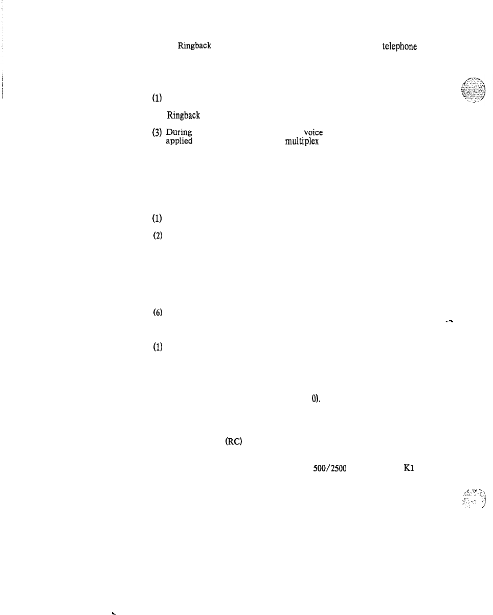
PRACTICE 553-2201-183
(12) Ringback
tone on the data output bus is applied to
telephone
during message time slot assigned by CE (busy tone received if
called number is busy).
5.04 Talking Connection.
(1)
Called party answers.
(2)
Ringback
tone removed by CE.
(3)
rp;m~
message time slot,. digital
,voice
on data output bus is
to telephone via
multrplex
control, PCM codec,
digital-to-analog filter and hybrid transformer.
(4) During the message time slot, analog voice from telephone is
applied to the data input bus via hybrid transformer,
analog-to-digital filter, PCM codec, multiplex control and buffer.
5.05 Terminating Call.
(1)
Telephone goes on-hook.
(2)
On-hook condition is detected by off-hook detector.
(3) Message sent to CE.
(4) CE detects removal of signaling.
(5)
The circuit enable inputs are removed and the message time slot is
no longer assigned to the line circuit.
CALL TO TELEPHONE
(6)
Circuitry in ‘idle’ condition, ready for next call.
5.06 Signaling the Called Telephone.
(1)
CE is continuously monitoring the status of line circuit (time slot 0
signaling).
_-
(2)
CE has call for line circuit 0.
(3) CE determines that line circuit 0 is idle (no signaling from circuit
on the data input bus during time slot
0).
(4) Signaling on the data output bus during time slot 0 is applied to
multiplex control.
(5) Ring Control
(RC)
signal from the multiplex control energizes
circuit at the rate determined by software.
(6) The 20 Hz ringing is applied to the
500/2500
telephone via
Kl
make-contacts and hybrid transformer.
5.07 Called Telephone Answers.
(1) Telephone goes off-hook, closing loop.
(2) Off-hook condition is detected by the off-hook detector during
the silent or ringing interval.
. . . . .
.
_.
.-
-.
,:;:I
:.
--‘
,.:
-..
‘_
‘.
!
Page 5-2
.
.
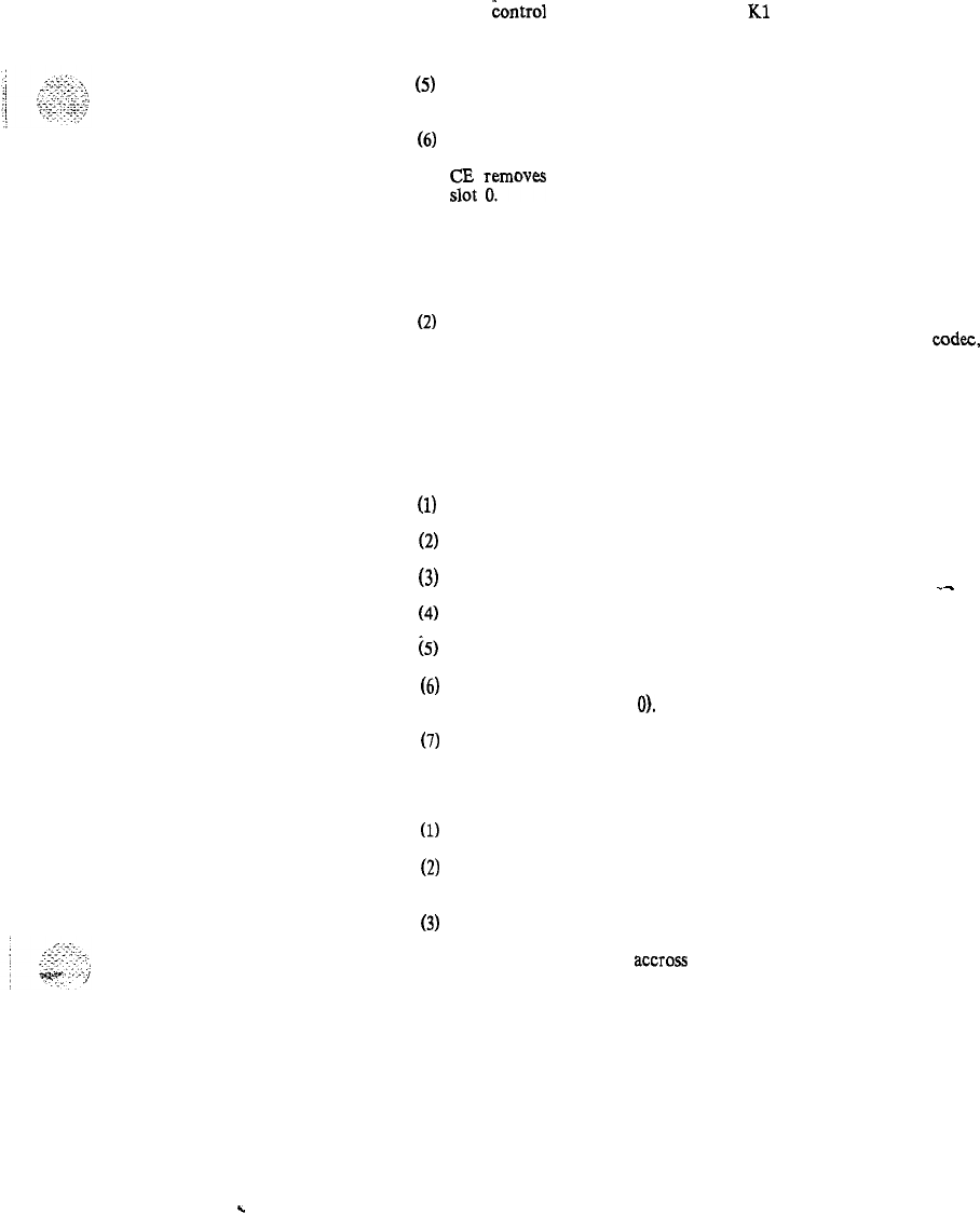
PRACTICE 553-2201-183
(3)
Ring
&ntrol
signal is removed.. Relay
Kl
is deenergized.
(4)
Ringing voltage is removed from called telephone.
(5)
Multiplex control sends off-hook signaling data to CE on the data
input bus during time slot 0.
(6)
CE detects signaling.
(7)
ztt
ymoves
ringing signaling on the data output bus during time
5.08 Talking Connection.
(1) Circuit and codec enable inputs are received during message time
slot assigned by CE.
(2)
During message time slot, digital voice on the data output bus is
applied to the telephone via multiplex control, PCM
codec,
digital-to-analog filter and hybrid transformer.
(3)
During message time slot, analog voice from telephone is applied to
the data input bus via hybrid transformer, analog-to-digital filter,
PCM codec, multiplex control and buffer.
. .
5.09 Terminating the Call.
(1)
(2)
(3)
(4)
(5)
(6)
Called telephone goes on-hook.
On-hook condition detected by off-hook detector.
No signaling on the data input bus during time slot 0.
_-
CE detects removal of signaling.
Signaling for line circuit is removed from data output bus.
Circuit enable inputs removed (message time slot is no longer
assigned to line circuit
0).
(7)
Circuitry in ‘idle’ condition, ready for next call.
MESSAGE WAITING
LAMP OPERATION 5.10 Message Waiting Lamp Activation.
(1)
Telephone idle.
(2)
CE receives a signal from the message center and sends it to the
message waiting line circuit.
(3)
The message waiting lamp control on the message waiting line
circuit places -150 V across tip and ring to light the lamp at the
telephone and -48 V
accross
-48 V and GND pair to the lamp
bank.
(4)
Telephone goes off -hook.
Page 5-3
.
.

PRACTICE 553-2201-183
GROUNDBUTTON
OPERATION
(5)
The off-hook condition is detected by the line circuit and the lamp
control removes the -150 V from the tip and ring of the
telephone. The message waiting lamp is deactivated.
(6) Telephone goes on-hook.
(7) The on-hook condition is detected by the line circuit,, the lamp
control places -150 V on the tip and ring of the telephone and
restores the message waiting lamp to the lit state.
5.11 Message Waiting Lamp Cancellation from Telephone.
(1)
Telephone originates a call to the message center.
(2) The off-hook condition is detected by the message waiting line
circuit and the lamps at the telephone and at the lamp bank are
deactivated.
(3) The message center answers.
(4) The CE signals the line circuit and the message lamp control
cancels the message waiting condition.
(5) Telephone goes on-hook.
(6) Message waiting lamp remains unlit.
5.12 Message Waiting Lamp Cancellation from Message Center.
(1)
The CE receives a signal from the message center to cancel the
message waiting condition.
(2) The message waiting line circuit receives the signal from the CE
and the message waiting lamp control removes the -150 V from
the tip and ring of the telephone and the -48 V from the lamp
bank.
--
(3) The lamp is deactivated and the message waiting condition is
cancelled.
5.13 Ground Button Depressed While on an Established Call:
(1)
Ground button detector on the QPC532 sends a ‘ground detected
signal to the scan and signal distributor.
(2)
T:;zSD
encodes a signal and sends it to the central processing unit
(3) The CPU provides a special tone to the party that depressed the
ground button and places the other party on hold.
Page 5-4
.
.

:‘.?..
^
._-.
.
._.
-.,...-..
y..,-.
M.,‘...,-;::
.._
.:
. .
PRACTICE 553-2201-183
CLASS OF SERVICE
AND FEATURES 5.14 All calls originating from and, terminating on stations connected to
line and trunk circuits may be controlled with or without attendant
assistance. Call restrictions to the exchange network and special services
are assigned through unique station/line circuit data blocks contained in
the system memory. Similarly, feature assignments are arranged through
the same data blocks. Refer to
552-2YYl-105
for a complete list and
description of features and services. Refer to
552-2YYl-310
for a
description of how features and
.services
are created in the system
memory.
Page 5-5
.
.
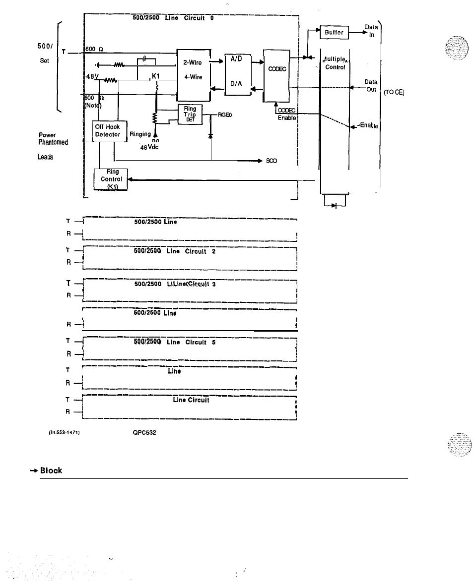
PRACTICE 553-2201-183
TO
5001
2500
T-.
set
:
l-4--
Audio and
Signaling
PCWN
Phantomed
Over These
Leads
l+l
_
2-Wire
---*
A’D
Filter
-
TO
LB&
,Kl
4-Wire
c
Conversion
D/A
+
Filler
+
. Superimposed
on
-48
Vdc
from backplane
i
Ring Control
I
r-
-------------------------------
i
c---------------------------------
T-i
500/2500
Line
Circuit 1
I
Fl+
I
I
L----------------------------------:
T
i~---------------------------------l~
500/2500
Line
Clrcult
2
I
4
R~-___---_____-_____________________l
T
i~--------------------------------~
50012500
Line
Circuit
3
I
Fl+
I
I
L-----------_---------------------
r-----------------_---------------
T-i
500/2500
Line
Circuit 4
1
I34
I
!
T
id---------------------------------?
500/2500
Line Circuit 5
I
R-/
1
L___--_-----_--_-------------------
r------------------_--------------
T
i 50012500
Llno
Circuit 6
I
R+
1
I
~---------------------------------,’
r_--------------------------------
”
50012500
Line
Circuit
7
I
R--;
I
1
L-------------------------------~
(111.553-1471)
Note:
QPC532
matches 3 component complex impedance.
Fig. 5-l
+
Block
Diagram of a double density 50012500 Line Pack
Oultiple
-Enat
PE Shelf
Backplane
V’
W
Page 5-8
.:
:
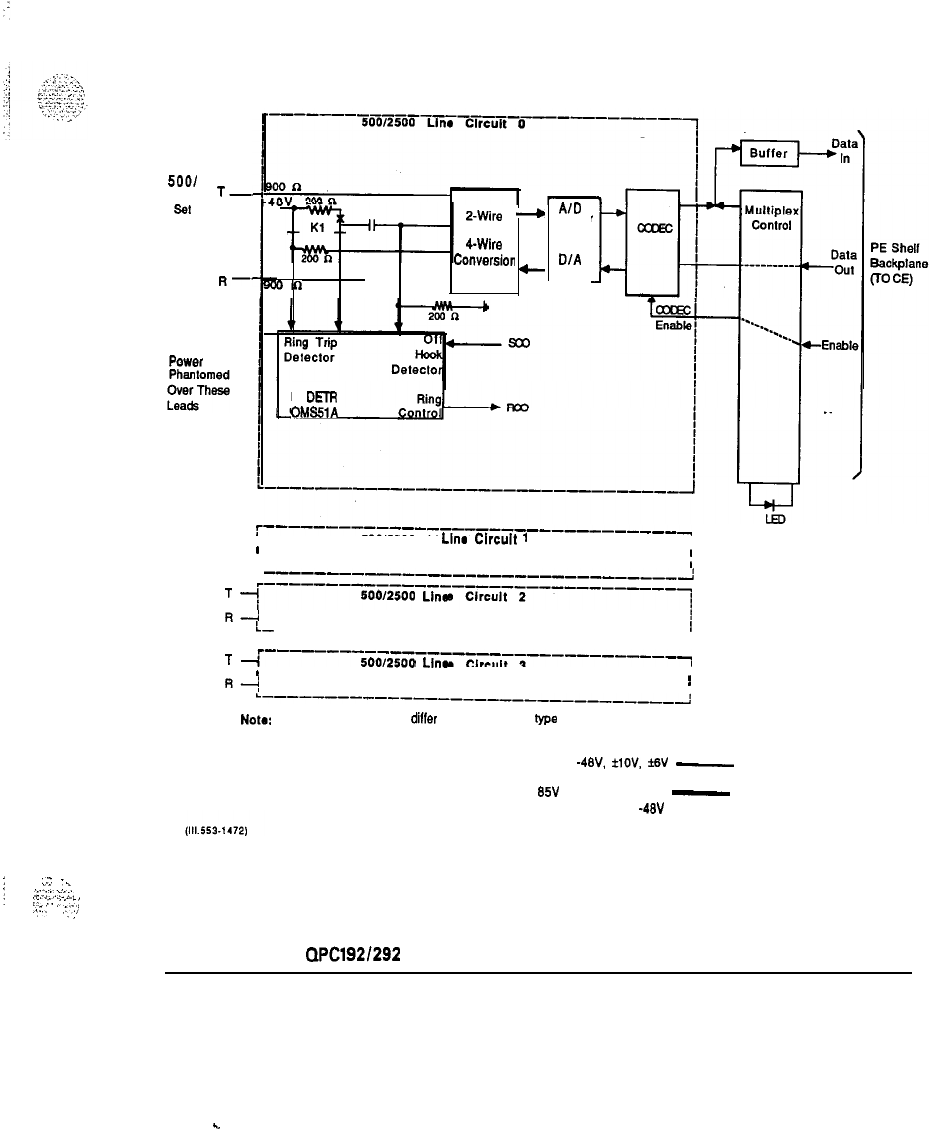
PRACTICE 553-2201-183
TO
5001
2500
T-.
set
I
R-’
Audio and
Signaling
Power
2-Wire
---*
A’D
Filler
TO
CWh
Conversior DIA
-
Filter
On
LP
DETR
OMS51A
r_-----_--~--~--~--~---~--~-~~~-~~~
T-i 50012500
Line
Circuit
1
I
R-i
I
L
I
-------------------------------A
T
1:--------------------------------
600/2500
Line
Clrcult 2
R-i
L-
i
------------------------------
T
i--------------------------------
500/2500
Lln.
Clrcult 3
I
R+
I
L-_--_-----_--_-_-__---------------
Note
A ringing value may
dilfer
depending upon
type
of
ringing generator pack used.
GRD,
-48V.
flOV,
MV
-
Power
85V
rms 20 Hz (Note)
-
Ringing
Superimposed on
-48V
dc
1
.J
-.
j
2:.:I..‘;::.
:.’
.:._
‘-
.:,
:,
:
..,z:
;-,,‘
Fig. 5-2
Block Diagram of
QPClg2/292
Line Pack
Page 5-7
c
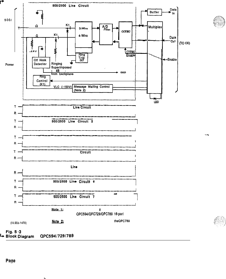
PRACTICE 553-2201-183
P
.
TO
5001
2500
Set
T-
R-
.
Audio and
Signaling
POWN
Phantomed
Over These
Leads
________________________________________----------------------~-------.
500/2500
Line
Clrcult
0
600
n
x
TO
600
Cl
Kl, 4-Wire
Conversion DIA
-
Filter
6
Enab
on
46
Vdc
Ring Control
-
Control
-
.______ -_.
_----------_-__---~_-------~~~~~~~~
‘1
50012500
Llna
Clreult
1
fl+
I
----------------------B-----------J
Tl
---------
5oo/2sopun.---l~~
-----
-------~
RA
I
I
----------------------------------~
T
-r---
----~----------~-------~~~~~~~
50012500 Line Circuit 3 1
I
R+
1
I
---------------------------~~-~~~~J
---_-----_-----_-------------------
Ti
50012500 Line
Circuit
4
I
R
4:
I
I
L-------------------------------!
-----------------------------------
T-i 50012500
Line
Circuit 5
I
!
R
4:
L---------------------------~-~~~~
i
T
“~-----‘----------------------------’
5OOl2500
Line
Clrcult
6
R---;
II
i,--,---,--,----------------,---,-----A
T-I
‘-----~---5~ocrsoo~~~-~,~~~,~~
------
-
-----
lo
I
I34
I
i----------------------------------!
NQt9Ji
There is an additional
8
line circuits (line circuits 6-15)
on the
QPC594/QPC729/QPC769
l&port
line cards.
m
This circuitry is only supplied on
theQPC769
circuit Packs.
4
E;%E
iiegrem
of
QPC594/729/789
Line Pack
Dal
-0u
CEnab
PE Shelf
Backplane
CrO
W
Pege
5-8
.-
c
nit
northern
ttdocom
PRACTICE 553-2201-193
Issued: 87 08 31
Standard
INTEGRATED SERVICES NETWORK
MERIDIAN
SL-I..
QPC578 INTEGRATED SERVICES DIGITAL
LlNE
CARD
DESCRIPTION
CONTENTS
PAGE
1.
QPC578 INTEGRATED SERVICES DIGITAL LINE
CARD . . l-l
Description
:..
l-1
Functions
.._.........
l-2
Reason for Reissue: This practice is reissued to add further
reference information on digital telephones. Changes are indicated by
arrows in the margin.
Pm,cd
I”
CSA
’
Northern
Telecom
Limited 1985
Page i
1 Page

,..,
.i.
“‘;;.:-.7;;.
:,
.
..I.
_.
:
j
.
.
.
.
...)
I
.
PRACTICE 553-2201-193
1. QPC578 INTEGRATED SERVICES DIGITAL LINE CARD
Description
.;
:
.
1’.....
i
,_:_:.,
,..
.
I
.I,.“.’
./
1.01 The QPC578 Integrated Services Digital Line Card (ISDLC) is a
voice and data communication link between a Meridian SL-1 and the
Meridian
M2000/M3000
series of digital telephones. When a digital
telephone is equipped with the data option, an asynchronous ASCII
terminal or PC can be connected to Meridian
SL-1
through the digital
telephone. The ISDLC circuit pack supports voice only or simultaneous
voice and data service over a single twisted pair of standard telephone
wiring. This practice describes the ISDLC. For more information on
Meridian digital telephones, see 553-2201-110 and 553-2201-111 for the
M2000 series telephones, the 553-2201-115 for the M3000 telephone,+
and the 553-2201-113 for the M2317 telephone.
c
1.02 Requirements. To use the ISDLC, the following Meridian SL-1
requirements must be met:
l Double Density Peripheral Shelves must be equipped (one shelf per
loop)
. Generic X11, Release 7 (or later) or Generic
X08.
Release 10
(or+
later) software must be running.
c
l Quadruple Density loops must be defined in hardware
(SW5
set to
ON on the associated Peripheral Buffer) and software (OVL 17)
l At remote locations using Remote Peripheral Equipment (RPE),
ISDLC packs must be QPC578B. series C or higher.
1.03 The QPC578 ISDLC is equipped with eight identical line circuits.
Each line circuit provides a multiplexed voice, data and signaling path
to and from digital apparatus over a 2-wire full duplex 512 KHz Time
Compression Multiplexed (TCM) digital link.
.-
1.04 Time Compression Multiplexing. Once every 125
usecond.
the
ISDLC transmits a 23 bit message to a digital telephone. At the end of
the 23 bit message a 2.7 bit guard band delay is inserted. Then the
digital telephone begins transmitting a similarly formatted 23 bit
message to the ISDLC. Each 23 bit message consists of:
l
start (1 bit)
l
voice signaling (1 bit)
l voice
vahd
(1 bit)
l
PCM voice (8 bits)
l
data signaling (1 bit)
l
data valid (1 bit)
l
data (8 bits)
l
parity (1 bit)
l
stop (1 bit)
Page 1-l
6 Pages
PRACTICE 553-2201-193
1.05 Meridian SL-i Data Block. Each digital telephone and each
associated data terminal is assigned a separate Terminal Number (TN) in
the Meridian SL-1 data base.
Functions
Page l-2
1.06 Physical. ISDLC circuitry is contained on a 320 mm (12.5 in) by
254 mm
(10
in) printed circuit board. The faceplate of the pack is
equipped with a red LED which lights if the pack is disabled. The rear
of the pack is equipped with an IO-pin connector which provides access
to:
l digital telephones (and associated ASCII terminals or PCs if
equipped)
l
Peripheral Bus
l
power supply
1.07 Configuration. Up to six ISDLC circuit packs can be mounted in
one PE shelf if the remaining slots are used: up to eight ISDLC circuit
packs can be equipped if the remaining slots
are-
left unused. In
addition, up to 18 ISDLC packs can be supported by a single
QPC82
Power Converter. This assumes that no other packs exist that require
power from that converter. If ISDLC circuit packs co-exist with other
peripheral packs associated with the same power converter, the
total..
number of ISDLC circuit packs is calculated as follows:
D
=
3/4
(24
-
Xl
where
D, an integer, is the maximum number of ISDLC packs allowed
X is the number of other circuit packs (e.g., QPC451) associated with
the same power converter.
--
Note: When ISDLC circuit packs serve M3000 Touchphones, this
restriction does not appiy because Touchphones are locally
powered.
1.06 Power
SUDDIV
to Digital Telephones. The ISDLC provides
+30
VDC over each
loop
at
amaximum’current
of 60
mA.
The iine feed
interface can supply power to loops of up to 1067 m (3500
ftl
length
using 22 or 24 AWG gauge wire. 26 AWG guage vire is limited to 745
m (2450 ft). Typical cabling and cross-connections are shown in Fig.
l-l.
1.09 The ISDLC handles messages sent to and from Meridian SL-1 and
digital telephones. Because the message formats and clocking used by
Meridian SL-1 and the digital telephones are different, the ISDLC must
be able to correctly format and synchronize all messages going to and
from these devices. The ISDLC performs the following major tasks:
(a)
Provides 8 bidirectional BPRZ-AM1 coded TCM lines at 512 kbps
to interface up to 8 digital telephones and their associated Data
Options.
._
. . .
9.:;.
.‘.l$
(bl
Multiplexes and demultiplexes 8 integrated voice and data lines and
a 2.56 Mbps DS3OX data stream (used internally by ISDLC)
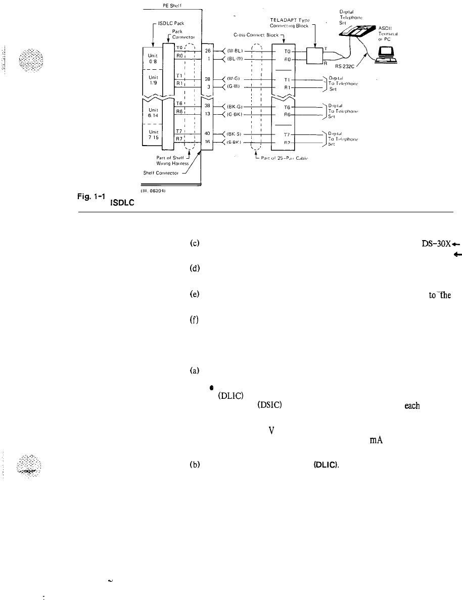
PRACTICE 553 -2201-193
Typical
ISDLC
Cabling and Cross-Connections
(c)
(d)
(e)
(f)
Converts the Meridian SL-1 bit interleaved data format to
DS-30X+
format and vice versa.
4-
Converts Meridian SL-1 SSD (signaling) messages to TCM format
and vice versa.
Synchronizes the digital telephones and their data options
to-the
Meridian SL-1.
Provides buffering of messages to compensate for different
signaling rates
1.10 The ISDLC consists of the functional blocks shown in Fig. 1-2.
Each block incorporates the following main functions:
(al
TCM Loop interface.
*
Couples 8 identical TCM loops from the Digital Line Interface
(DLIC)
functional block of the ISDLC to the Digital Set
Interface
(DSIC)
functional block located in
each
digitial
telephone in both the transmit and receive directions.
l Provides i-30
V
battery feed to each digital telephone through a
voltage regulator, configured as a 60
mA
constant current
source.
(b)
Digital Line Interface
(DLIC).
The DLIC provides the
communication link between 8 digital telephones (including their
associated Data Options) and the Meridian SL-1 peripheral bus.
The DLIC performs the following functions:
Page l-3
s.
:
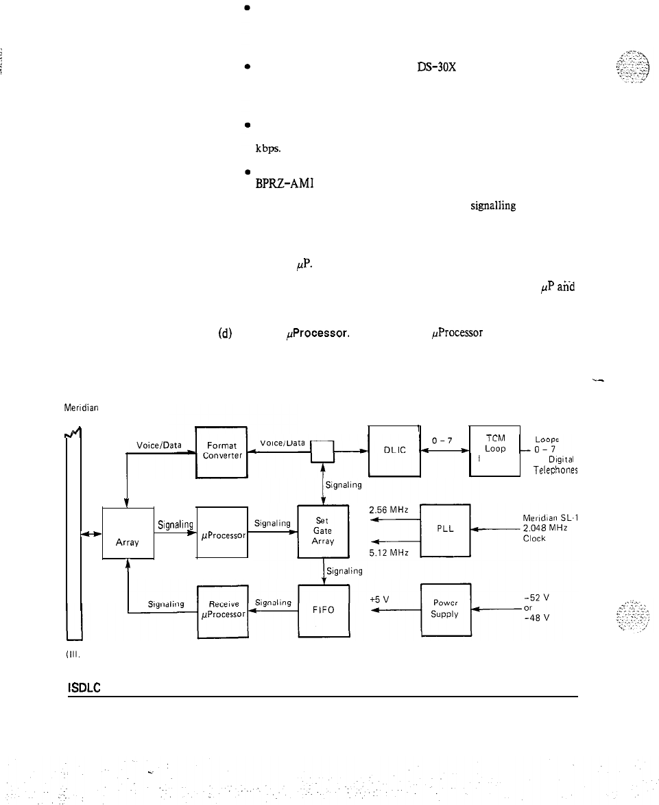
PRACTICE 553-2201-193
Multiplexes-8 integrated voice and data TCM lines into a 2.56
Mbps DS-30X formatted data stream (used internally in the
pack) when the transmission is from the digital telephone or
associated terminal to the Meridian SL-1.
De-multiplexes the 2.56 Mbps
DS30X
formatted data stream
into 8 integrated voice and data TCM line-s when the
transmission is from the Meridian SL-1 to the digital telephone
or associated terminal.
Provides a station line transmitter for 8 channels, each of which
transmits BPRZ-AM1 coded data over the TCM loop at 512
kbps.
provides 8 station line receivers, each of which receives
BPRZ-AMI data from a TCM loop independantly at 512 bps.
(c)
Set Gate Array. The Set Gate Array handles
signalling
conversion
for up to 8 integrated voice and data lines.
l Receives signaling bits (8 voice and 8 data) from digital
telephones and transfers the data in bytes via the FIFO to the
Receive
PP.
l Accepts DS-30X signaling messages from the Transmit
PP
and
inserts the packets bit by bit to the appropriate signaling
channel.
(d)
Transmit
FProcessor.
The Transmit
PProcessor
receives outgoing
Meridian SL-1 SSD messages (i.e., signaling) from the Peripheral
Gate Array and:
l
Converts outgoing SSD messages to DS-30X format.
Meridian
SL-1
Peripheral Bus
4
TCM
’
Loops TCM
Interface To
DigItal
Telephoto
1
Peripheral
-
Gate
Signaling
Transmit
Array
e
/JProcessor
4
(Ill.
06395)
Fig. l-2
ISDLC
Block Diagram
Page l-4
.-
PRACTICE
553-2201-193
l If
required,
packetizes
several
SD
messages into one DS-30X
message.
(e)
Receive
/1Processor.
The Receive
~Processor
receives incoming
signaling messages from digital telephones, via the Set Gate Array
and:
l Converts incoming
DS30X
signaling messages to SSD message
format.
l Will repacketize a long message into several SSD sized
(2-bytes)
messages when required.
(f)
Format Converter.
l Converts the Meridian SL-1 voice and data bii-interleaved
format to DS-30X byte-interleaved format.
0
Converts the incoming DS-30X byte-interleaved format to
Meridian SL-1 bit-interleaved format.
(g)
Peripheral Gate Array.
l Provides a bi-directional interface for voice and data-between
the Meridian SL-1 Peripheral Bus and the Format Converter.
l Provides serial to parallel conversion of signaling data received
from the Meridian SL-1 Peripheral Bus and transfers the data
to the Transmit
PP.
l Provides parallel to serial conversion of signaling data received
from the Receive
FP
and transfers the data to the Meridian
SL-1 Peripheral Bus.
-
(h)
Phase Locked Loop.
0
Ensures phase and frequency stability and correlation between
incoming signals from the digital telephones and signals on the
ISDLC.
0
Three clocks, 2.56 MHz, 4.096 MHz and 5.12 MHz, are derived
from the PLL and synchronized to the 2.048 MHz Meridian
SL-1 clock.
(i)
Power Supply.
l An
onboard
DC-to-DC converter takes either -52 VDC or
-48 VDC input and generates the i-5 VDC required by the
ISDLC logic circuits.
l
up to 2 A with 5% regulation
Page l-5
.
.
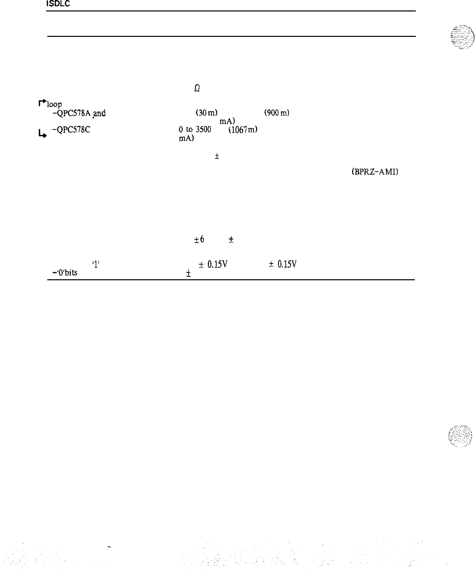
PRACTICE 553-2201-193
Table 1-A
ISDLC
CIRCUIT CHARACTERISTICS
CHARACTERISTICS DESCRIPTION
circuits per pack
options
impedance
8 voice/data
nil
100
R
I+loop
limits
-QPC578A
,and
B 100
(30
m)
to 3000 feet
(900
m)
with 24 AWG PVC cable (i-30
VDC at 60 mA)
,+
-QPC578C
0$3500
feet
ilO67
m)
with 24 AWG PVC cable (i-30 VDC at 60
line rate
line coding
power supply
512 kbps
&
100 ppm
bipolar return-to-zero alternate mark inversion
(BPRZ-AMI)
-52 VDC unregulated
or
-48 VDC regulated
and
k6
VDC,
f
15 VDC. i-10 VDC
transmitter output voltage
-successive
‘1’
bits
-‘O’bits
i-l.5
+
0.15V
and -1.5
f
0.15V
0
+
50mV
Page l-6
