Meru Networks AP100 802.11b Access Point User Manual PhysInstallguide
Meru Networks Inc. 802.11b Access Point PhysInstallguide
Contents
- 1. professional installation
- 2. users manual 2
users manual 2

Installing the Meru Air Point 100 1
Revision 0.1, September 2003 (9/22/03)
Installing the Meru Air
Point 100
This document describes how to physically install a Meru Air Point 100 wireless
network access point.
Unpacking the Access Point
Confirm that the following are in the access point package:
zAccess Point
zMounting bracket
zLight-pipe extender
zTwo small mounting screws
zRegistration card
zThis guide
Installation Requirements
There are four ways of mounting the access point:
zOn a horizontal surface, such as a table or a desk.
zOn a vertical surface, usually a wall.

2Installing the Meru Air Point 100
Revision 0.1, September 2003 (9/22/03)
Installing the Access Point
zUnderneath a horizontal surface, usually a ceiling.
zAbove a ceiling tile.
To complete this installation, you need the following consumable items:
You need the following tools:
Installing the Access Point
Selecting a
Location The access point requires a location that has both
Installation Type Consumable Items Required
Horizontal mounting None
Vertical mounting over a wall stud zTwo #6 screws
Vertical mounting on sheetrock zTwo #6 screws
zTwo plastic wall anchors
Horizontal mounting below a ceiling zTwo #6 screws
zTwo plastic wall anchors
Mounting above a ceiling tile zTwo #6 screws
Installation Type Tools Required
Horizontal mounting None
Vertical mounting over a wall stud zDrill
z1/8-inch drill bit
zScrewdriver
Vertical mounting on sheetrock zDrill
z3/16-inch drill bit
zScrewdriver
Horizontal mounting below a ceiling zDrill
z3/16-inch drill bit
zScrewdriver
Mounting above a ceiling tile zDrill
z1¼-inch hole saw
zScrewdriver

Installing the Meru Air Point 100 3
Revision 0.1, September 2003 (9/22/03)
Installing the Access Point
zRelatively unobstructed access to the mobile stations that it will serve
zA power-over-Ethernet connection to the network switch servicing the controller
The access point communicates with mobile stations using radio waves like those
used by cordless phones. These radio waves can go through walls, floors, and
windows, but all of these reduce the range. Find a location where the radio waves can
get to the mobile station with as little obstruction as possible. In an office with cubi-
cles, mounting the access points on the ceiling or on the wall near the ceiling might
allow the radio waves to avoid furniture and cubicle walls.
The location must also have a 100BaseT power-over-Ethernet (PoE) connection from
the access point to the switch for the controller. The power can be supplied by a PoE
switch or by a PoE power injector between the switch and the access point.
Attaching the
Antennas Attach the antennas to the connectors on the access point and hand tighten.
Mounting the
Access Point Horizontal Mounting
1. Place the access point flat on the horizontal surface.
2. Point the antennas up.
3. Connect the PoE 100BaseT Ethernet cable.
Vertical Mounting
1. Mark the location for the two access point mounting screws. They must be 4 ½
inches apart, center-to-center, one above the other. If you are not using plastic wall
anchors, you must center the mounting screws on a wall stud. If you do not center
the mounting screws on a wall stud, you must use plastic wall anchors.
2. Drill holes at the locations you marked:
—3/16-inch holes if you are using plastic anchors
—1/8-inch holes if you are using only the screws
3. If you are using plastic anchors, install them in the holes.
4. Screw in the screws most of the way, so that the screw head is about 1/16 of an
inch from the wall.
5. Mount the access point on the screws, placing the circular portion of the keyhole
mounts over the screw heads and sliding the access point down.
6. Point the antennas up.
7. Connect the PoE 100BaseT Ethernet cable.
Mounting Below a Ceiling
1. Mark the location of the two mounting screws. They must be 4 ½ inches apart,
center-to-center.
2. Drill holes at the locations you marked:

4Installing the Meru Air Point 100
Revision 0.1, September 2003 (9/22/03)
Installing the Access Point
—3/16-inch holes if you are using plastic anchors
—1/8-inch holes if you are using only the screws
3. If you are using plastic anchors, install them in the holes.
4. Screw in the screws most of the way, so that the screw head is about 1/16 of an
inch from the wall.
5. Mount the access point on the screws, placing the circular portion of the keyhole
mounts over the screw heads and sliding the access point down.
6. Point the antennas down.
7. Connect the PoE 100BaseT Ethernet cable.
Mounting Above a Ceiling Tile
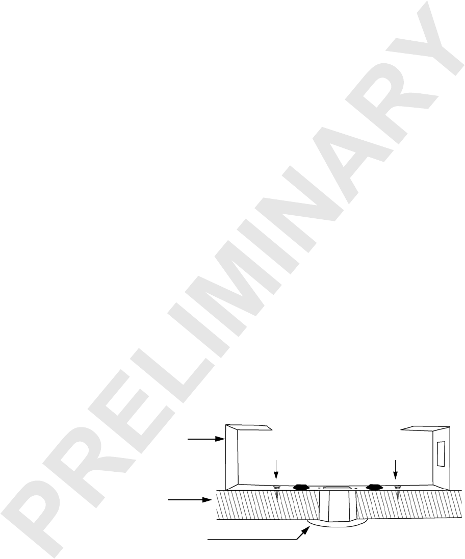
1. Remove the ceiling tile where the access point will be located.
2. Confirm that there is at least 6 inches of space above the ceiling tile to accommo-
date the access point antennas. If there is insulation above the ceiling tile, clear it
for at least three inches to the side and three inches above the access point.
3. Cut a hole in the tile, 1¼ inches in diameter, for the access point light-pipe
extender. The hole should be at least 6 inches from the edge of the tile.
4. Insert the light-pipe extender into the hole, with the 2-inch flange on the appear-
ance side of the ceiling tile.
5. Attach the mounting bracket to the light-pipe extender, with the two small pins
on the light-pipe extender fitting into the small holes on the mounting bracket and
the two hooked tabs fitting into the two notches in the mounting bracket hole.
Note that the tabs are different widths and the wide tab fits only into the wide
notch. Press the tabs in towards each other to clear the edges of the notch. They
will lock in place.
6. Attach the mounting bracket to the ceiling tile, using two #6 screws.
Figure 1: Mounting Bracket and Light-Pipe Extender, as Installed on a Ceiling Tile
Mounting bracket
Ceiling tile
Light-pipe extender
#6 screw #6 screw

Installing the Meru Air Point 100 5
Revision 0.1, September 2003 (9/22/03)
Installing the Access Point
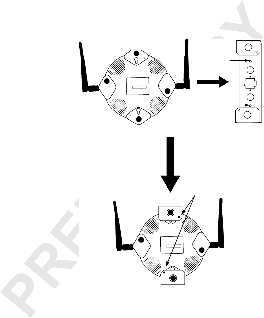
7. Slide the access point into the mounting bracket as shown in the following
diagram. Slide the bracket’s feet over the two feet of the access point closest to the
keyhole mounts.
Figure 2: Attaching the Access Point to the Mounting Bracket
8. Position the small holes on the bracket over the small holes on the back of the
access point. Use two screws supplied to attach the bracket to the access point.
9. Point the antennas up.
10.Return the ceiling tile to the ceiling, but leave the tile loose.
11. Connect the PoE 100BaseT Ethernet cable to the access point.
12.Reposition the antennas, if needed.
13.Replace the ceiling tile in the ceiling brackets.
Attach with
Slide into
bracket
mounting screws
#6 screw
#6 screw

6Installing the Meru Air Point 100
Revision 0.1, September 2003 (9/22/03)
LED Activity
LED Activity
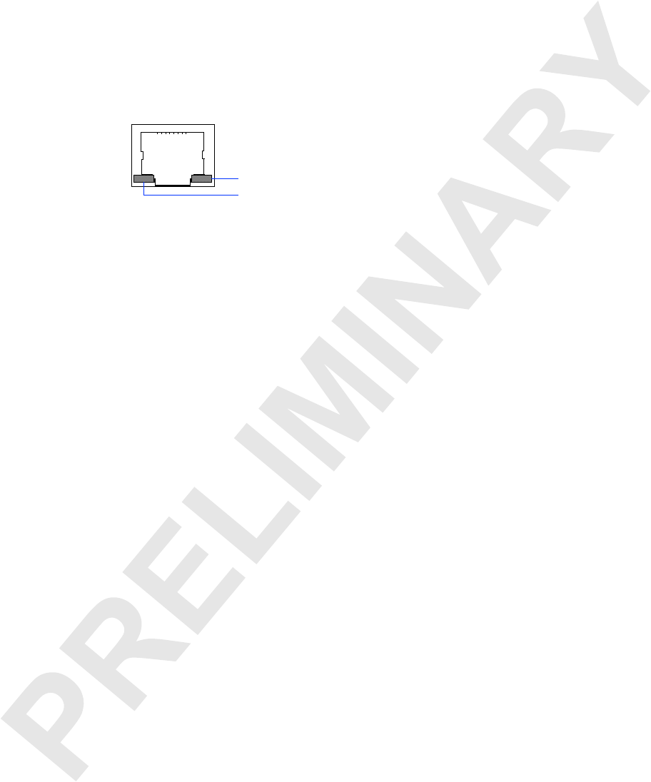
After the Air Point 100 access point is connected, the LEDs near the RJ-45 connector
should light.
Figure 3: RJ-45 LEDs
The green LED on the left indicates that Ethernet activity is taking place. The LED on
the right indicates that an Ethernet link is present. If this LED is yellow, the link is a
100BaseT link. If this LED is green, the link is a 10BaseT link.
The some of four LEDs on the face of the access point will also light. The LED closest
to the Meru logo and furthest from the Ethernet port lights green to indicate the pres-
ence of power. The other LEDs are explained in the System Administrator’s Guide.
Link present: yellow = 100MB; green = 10MB
Ethernet activity

Installing the Meru Air Point 100 7
Revision 0.1, September 2003 (9/22/03)
Other Sources of Information
Other Sources of Information
This guide is part of the Meru wireless LAN documentation set, which also includes:
zMeru Air Traffic Control System Command-Line Interface Reference, which provides
an alphabetic listing of all of the commands available through the Meru
controller’s console interface.
zMeru Air Traffic Control System System Administrator’s Guide, which provides
detailed information on configuring, using, monitoring, and troubleshooting the
Meru wireless LAN, its controllers and access points, and its connections to
external network services. It describes how to perform typical tasks using both
the CLI and the Meru graphical user interface.
zMeru Air Traffic Control System Release Notes, which lists information about the
latest software release.
zMeru Air Traffic Control System Installation and Quick Start Guide, which describes
how to install the Meru wireless LAN and configure the basic parts of a Meru
wireless networking environment.
In addition, the Meru Web site provides information on products, support, and the
company. See “Contacting Meru” on page 7.
Contacting Meru
You can reach Meru’s automated support services 24 hours a day, every day at no
charge. The services contain the most up-to-date information about Meru products.
You can access installation instructions, troubleshooting information, and general
product information.
Web and
Internet Sites You can use the Internet to download software updates, troubleshooting tips, instal-
lation notes, and more.
zGeneral online support services are on the World Wide Web at:
http://www.merunetworks.com
Customer
Support
Technicians
zUnited States and Canada: 408-215-5300 (7:00 - 17:00 M-F Pacific Time)

8Installing the Meru Air Point 100
Revision 0.1, September 2003 (9/22/03)
Safety Precautions
Safety Precautions
WARNING!
Inside antennas must be positioned to observe minimum
separation of 20 cm. (~ 8 in.) from all users and bystanders. For
the protection of personnel working in the vicinity of inside
(downlink) antennas, the following guidelines for minimum
distances between the human body and the antenna must be
observed.
The installation of an INDOOR antenna must be such that, under
normal conditions, all personnel cannot come within 20 cm. (~ 8.0
in.) from any inside antenna. Exceeding this minimum separation
will ensure that the employee or bystander does not receive RF-
exposure beyond the Maximum Permissible Exposure according
to section 1.1310 i.e. limits for General Population/Uncontrolled
Exposure.
WARNING!
The Outside antenna must be positioned to observe minimum
separation of 120 cm. (~ 4 ft.) from all users and bystanders. For
the protection of personnel working in the vicinity of outside
(uplink) antennas, the following guidelines for minimum distances
between the human body and the antenna must be observed.
The installation of an OUTDOOR antenna must be such that,
under normal conditions, all personnel cannot come within 120
cm. (~ 4 ft.) from the outside antenna. In all installations, the
antenna should never be mounted such that the main beam is
directed toward an area where workers or bystanders may be
present. Exceeding this minimum separation will ensure that the
worker or bystander does not receive RF-exposure beyond the
Maximum Permissible Exposure according to section 1.1310 i.e.
limits for General Population/Uncontrolled Exposure.

Installing the Meru Air Point 100 9
Revision 0.1, September 2003 (9/22/03)
Safety Precautions
FCC Compliance
This device complies with part 15 of the FCC Rules. Operation is subject to the
following two conditions: (1) This device may not cause harmful interference, and (2)
this device must accept any interference received, including interference that may
cause undesired operation.
C
AUTION
:
Changes or modifications to the Meru Air Point 100 access point which
are not expressly approved by Meru Networks could void your authority
to operate this equipment.

10 Installing the Meru Air Point 100
Revision 0.1, September 2003 (9/22/03)
Safety Precautions