Meru Networks AP1020 DUAL RADIO ACCESS POINT AP1000 User Manual AP Install
Meru Networks Inc. DUAL RADIO ACCESS POINT AP1000 AP Install
Users Manual

AP1000 Beta Test
Meru Access Point
Installation Guide
Copyright © Meru Networks, Inc., 2003–2010. All rights reserved.
Other names and brands may be claimed as the property of others.
August 2010
Document Number: 882-70037 Rev A Rel 4.0 Ver 20 Access Point Installation Guide
AP1000
© 2010 Meru Networks, Inc. Access Points 5
AP1000 Beta Test
AP1000
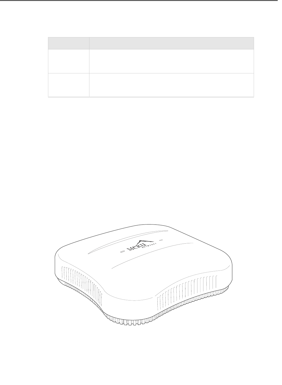
The AP1000 Access Point is an internal-antenna AP with either one or two dual-band
802.11n radios, 2x2 MIMO and internal antennas.
Features for the AP1000 include:
zInternal antennas
z802.11n suppport with channel bonding in both 2.4GHz and 5GHz frequency bands.
Channel bonding combines two 20MHz channels into a single 40 MHz channel for
increased throughput.
zPlug and Play deployment using centralized controller platforms
zMulti-layered security including standard WPA2 features such as automatic traffic
inspection
zStandard 802.3af PoE support and support for many 802.at services
zAir Traffic Control technology for 802.11n devices and legacy a/b/g devices
zChannel span architecture that requires no channel planning or configuration
Figure 4: AP1000
Model Configuration
AP1010i One dual-band 802.11n radio with 2x2 MIMO and internal
antennas
AP1020i Two dual-band 802.11n radios with 2x2 MIMO and internal
antennas
1

Safety Precautions
© 2010 Meru Networks, Inc. Installing AP1000 55
AP1000 Beta Test
Chapter 4
Installing AP1000
AP1000 is supported by System Director versions 4.1 and greater. This chapter describes how to install
and configure an AP1000. It contains the following sections:
zSafety Precautions
zBest Practices for a Mixed Network
zUnpack the AP1000
zPower Requirements
zAdditional Equipment
zInstalling AP1000
zRestoring AP1000 Settings
zCheck AP1000 LEDs
zWhere to Go From Here
Safety Precautions
IMPORTANT—Read and follow the regulatory instructions in Appendix B before installing and operating
this product.
The AP1000 is only intended for installation in Environment A as defined in IEEE 802.3af. All intercon-
nected equipment must be contained within the same building, including the interconnected equip-
ment's associated LAN connection.
2

56 Meru Access Point Installation Guide © 2010 Meru Networks, Inc.
Best Practices for a Mixed Network
AP1000 Beta Test
Best Practices for a Mixed Network
Read this section if you have both AP1000 and AP300 active simultaneously on the same network. The
following best practices should be followed to get optimal performance from such a mixed network.
zAP320i and AP300 are interchangeable and fully compatible to share a virtual cell. It's like having
two AP300s with different antennas. The only difference is that AP320i is detected as a such in the
UI of the controller.
zIf possible, do not deploy AP1000 and AP300 at the same physical location; we recommend that
there be no overlapping coverage between AP1000 and AP300.
zIf AP1000 and AP300 do have overlapping coverage, you have two options. Deploy them on separate
channels or make sure the ESS profiles on both AP types are unique. The chart below shows two ESS
scenarios, one supported, one not supported.
Assumptions for the above best practices include:
zAP1000 is using Virtual Port with BSSID Virtual Cell.
zAP320i is using Virtual Port with BSSID Virtual Cell.
zAP1000s and AP300s are on the same channel. (AP1000 and AP320i could also be on different
channels.)
zAP1000s and AP320i is are on the same controller. (AP1000 and AP320i could also be on different
controllers as long as each controller has a unique controller index.)
Supported ESS Scenario AP1000 Configuration AP300 Configuration
Two Unique ESS profiles ESS Profile name in
controller is UniqueName1
ESS Profile name in
controller is UniqueName2
AP1000 and AP320i SSID
string over the air Meru Meru
Unsupported ESS Scenario AP1000 Configuration AP300 Configuration
Same ESS profiles ESS Profile name in
controller is same name
ESS Profile name in
controller is same name
AP1000 and AP320i SSID
string over the air Meru Meru
3
Unpack the AP1000
© 2010 Meru Networks, Inc. Installing AP1000 57
AP1000 Beta Test
Unpack the AP1000
AP1000 series beta test uses both the dual radio (AP1020) and single radio (AP1010) models. Confirm
that the shipping box contains the following:
zAP1000 with built-in ceiling mount clips. Each radio has two built-in antennas, so AP1010 has two
built-in antennas and AP1020 has four built-in antennas.
zLocking tool for ceiling mount locking. You can see a drawing of this in Figure 31.
Power Requirements
Radios on an AP1000 use 2x2 MIMO configuration. To power an AP1000, use either an 802.3af or 802.3at
PoE cable; either one works automatically with no configuration required. For a list of supported PoEs,
see the appendix Supported Power Over Ethernet Devices for Meru APs
Additional Equipment
The following AP1000 mounting options require the listed additional equipment:
.
Note:
If you want to lock AP1000 to the wall, you need the optional kit 840-00052
ACC-MNT-AP1000-01.
Installation Type Additional Equipment
Ceiling mounting on a
suspended ceiling with or
without locking
zEither an 802.3af or 802.3at PoE cable
Wall mounting
zEither an 802.3af or 802.3at PoE cable
zWall mount screws – Recommend #6, #8 (M3, M3.5)
4

58 Meru Access Point Installation Guide © 2010 Meru Networks, Inc.
Installing AP1000
AP1000 Beta Test
Installing AP1000
Select a Location
All AP1000 interconnected equipment must be contained within the same building, including the inter-
connected equipment's associated LAN connection. Ceiling mounting is recommended but wall
mounting is also supported. In addition, the AP1000 should be mounted in a location that meets the
following conditions:
zRelatively unobstructed access to the clients the AP serves. Select a location with minimal physical
obstructions between the AP and the wireless clients. We recommend planning for about 20 data
clients per radio (or per interference region) if you plan to use Virtual Port. This is the
recommendation for a data-only installation. Refer to the Meru Deployment Guides on the support
site for more information.
zIn an office with cubicles, mount the APs below a hanging ceiling or on the wall near the ceiling to
provide the least obstructed communications path.
zOn a wall, orient the AP1000 horizontally so that you can read the Meru logo without tilting your
head at 90 degrees - this orientation provides optimum MIMO performance.
zAP1000 is designed to provide 180 degree omni-directional coverage as illustrated below. Plan
placement with this pattern in mind.
Figure 30: Coverage Pattern for AP1000 When Ceiling Mounted
zIf you install AP1000 on a pole, keep in mind that coverage will be 180 degrees; the pattern shown
above would be directed sideways. We do not recommend mounting two AP1000s back to back on a
pole to achieve 360 degree coverage, however, because the two units could interfere with each
other.
Wall mounting with locking
zEither an 802.3af or 802.3at PoE cable
zLocking Kit 840-00052 ACC-MNT-AP1000-01
Ceiling mounting on a recessed
ceiling
zEither an 802.3af or 802.3at PoE cable
zRecessed Ceiling Mount Kit 840-0005x ACC-MNT-AP1000-02
Installation Type Additional Equipment
ceiling
floor
5
Installing AP1000
© 2010 Meru Networks, Inc. Installing AP1000 59
AP1000 Beta Test
Install the Access Point
You can mount AP1000 in any of the following ways:
zMount AP1000 Below a Suspended Ceiling
zMount AP1000 on a Wall
zMount AP1000 on a Wall Using the Optional Locking Kit
zSet AP1000 on a Shelf
zMount AP1000 Above a Suspended Ceiling (Plenum)
Mount AP1000 Below a Suspended Ceiling
AP1000 ships ready to mount below a suspended ceiling; the built-in clips snap onto a ceiling rail. To
mount an AP1000 below a suspended ceiling, follow these steps:
1. Remove the ceiling tiles at the location the AP will be mounted.
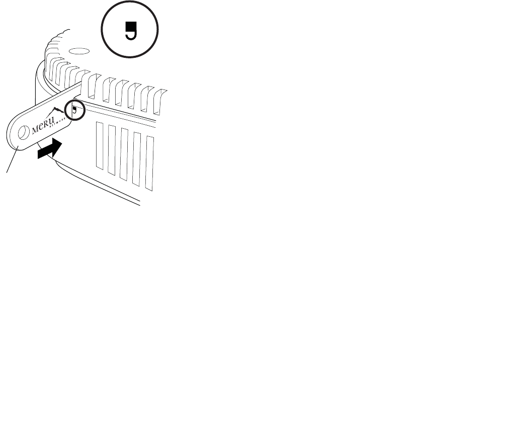
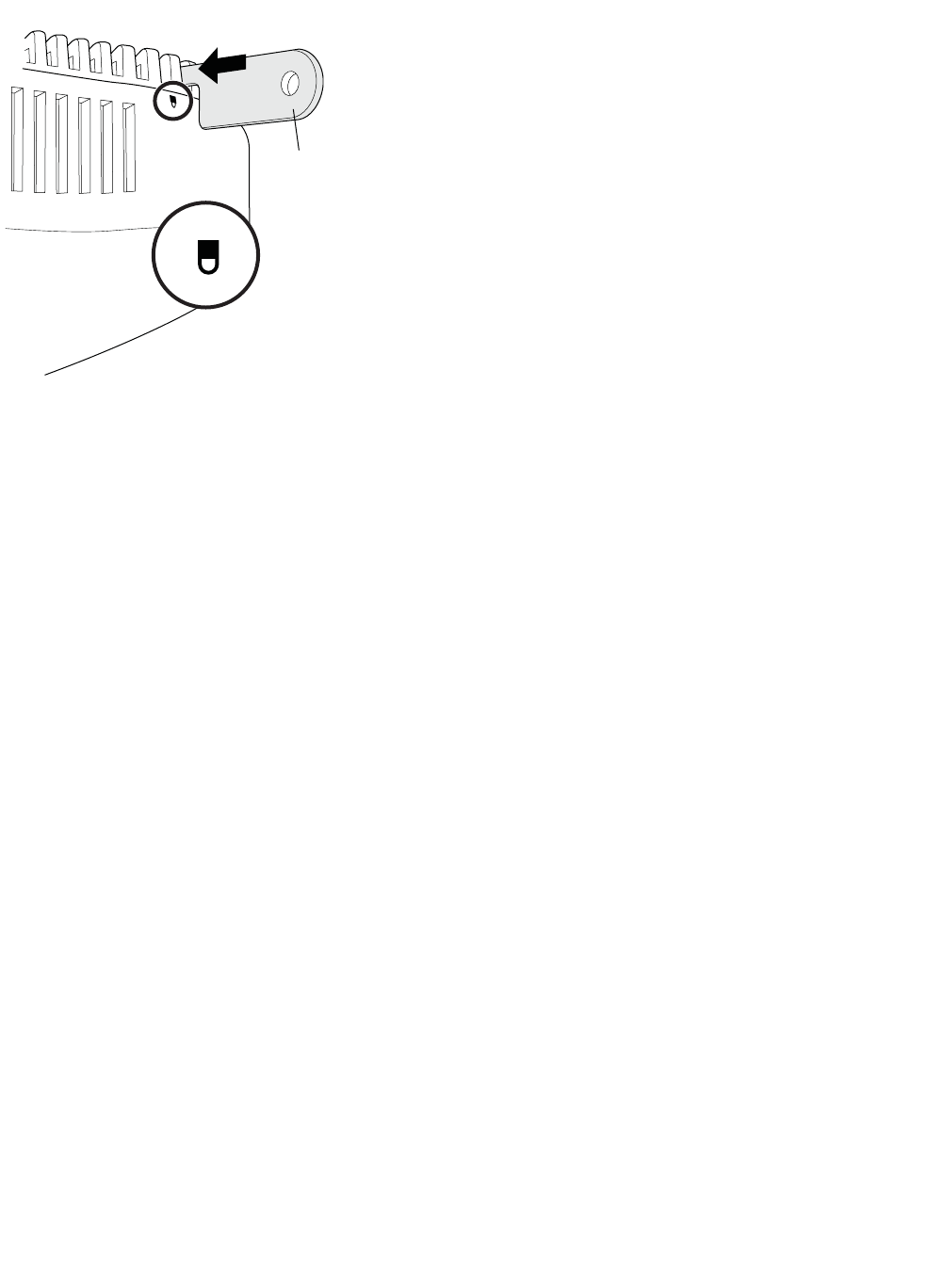
2. Be sure that AP1000 is not locked by inserting the locking key into the Unlock mechanism as shown
in Figure 31 below.
Figure 31: Unlock AP1000
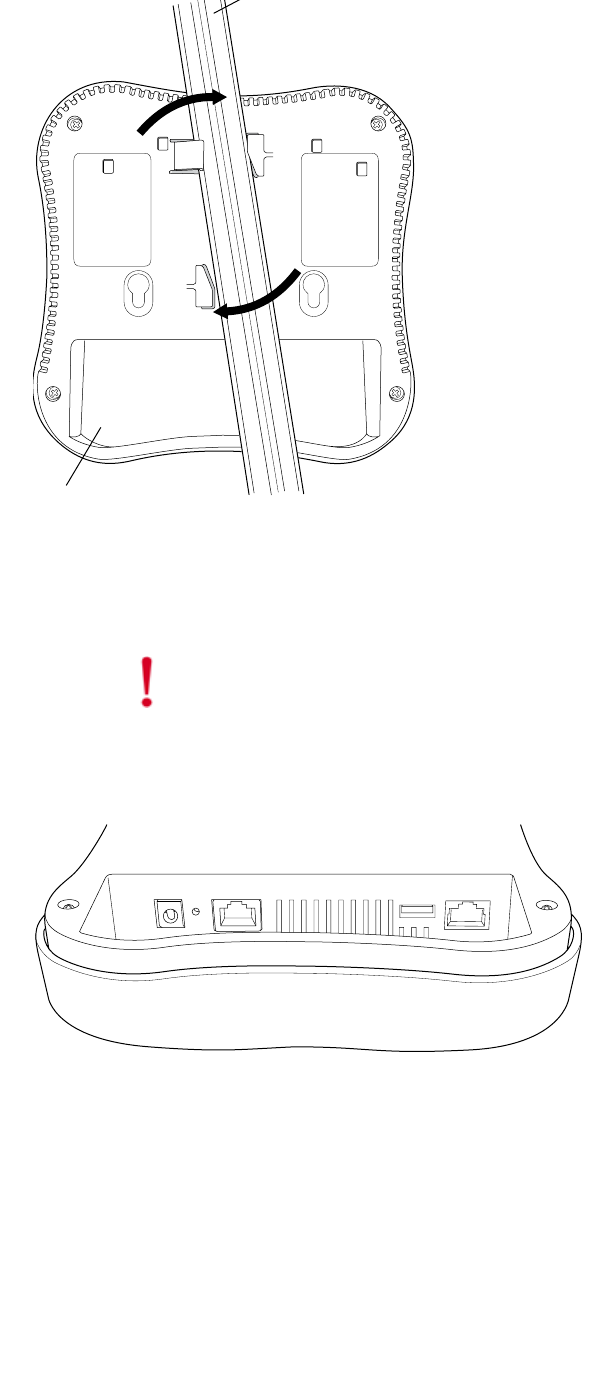
3. Align the ceiling t-bar with the AP1000 slots indicated in Figure 32 below.
00253
Key
UNLOCK
6
60 Meru Access Point Installation Guide © 2010 Meru Networks, Inc.
Installing AP1000
AP1000 Beta Test
Figure 32: Install AP1000 Below a Suspended Ceiling 247
4. Press down on the tab indicated in Figure 32 above and rotate the AP1000 into place.
5. Connect one end of the CAT5 (or greater) Ethernet cable with PoE to the 100/1000 Ethernet
connector shown in Figure 33 below.
Figure 33: AP1000 Ethernet Port
6. If you want to lock AP1000 in place, use the supplied locking tool to press the AP1000 locking
mechanism shown in Figure 34.
Caution!
Be sure to connect the Ethernet cable to the Ethernet port. The cable can
mistakenly be plugged into the Console port; if you do this, the AP won’t power up.
(in ceiling)
AP1000
00247
00248
7
Installing AP1000
© 2010 Meru Networks, Inc. Installing AP1000 61
AP1000 Beta Test
Figure 34: Optionally lock AP1000
7. To unlock AP1000, press the unlocking mechanism on the opposite side of AP1000 see Figure 31.
00254
AP1000 (mounted on ceiling)
LOCK
Key
8
62 Meru Access Point Installation Guide © 2010 Meru Networks, Inc.
Installing AP1000
AP1000 Beta Test
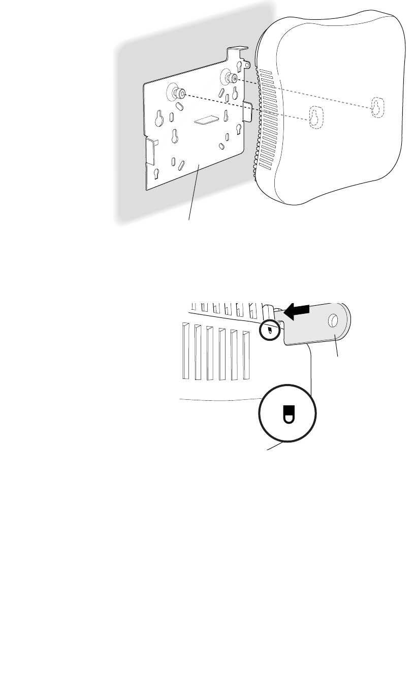
Mount AP1000 on a Wall
The AP1000 attaches directly to the wall. To mount an AP1000 on sheetrock or wall studs, follow these
steps:
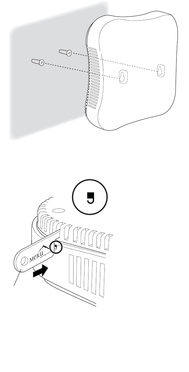
1. Attach two appropriate screws (see Additional Equipment for screw information) to the wall 3
inches apart (76mm) as shown below (Figure 35).
Figure 35: AP1000 Wall Bracket
2. Check to be sure that AP1000 is not locked by inserting the locking key into the Unlock mechanism
as shown below.
Figure 36: Unlock AP1000
00250
Wall mount with screws.
00253
Key
UNLOCK
9
Installing AP1000
© 2010 Meru Networks, Inc. Installing AP1000 63
AP1000 Beta Test
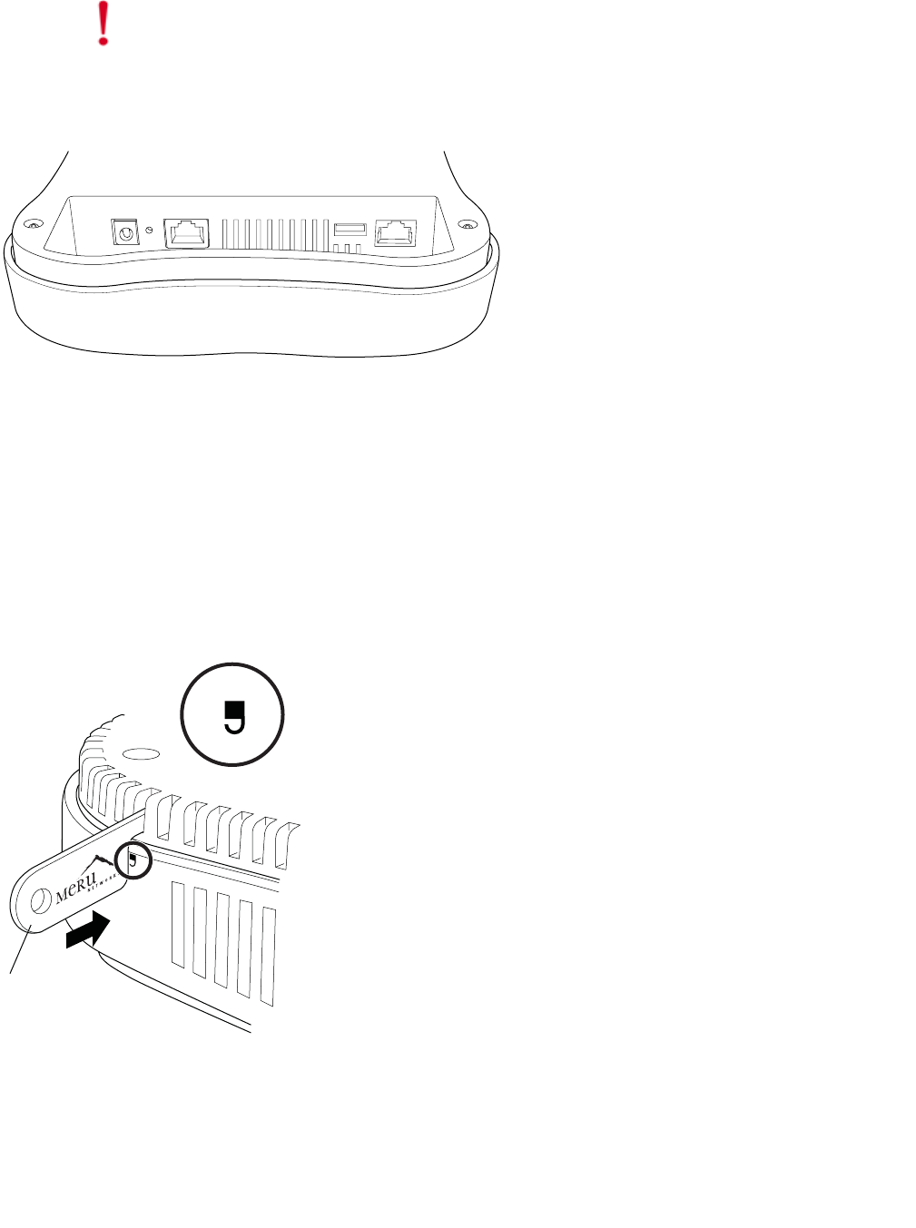
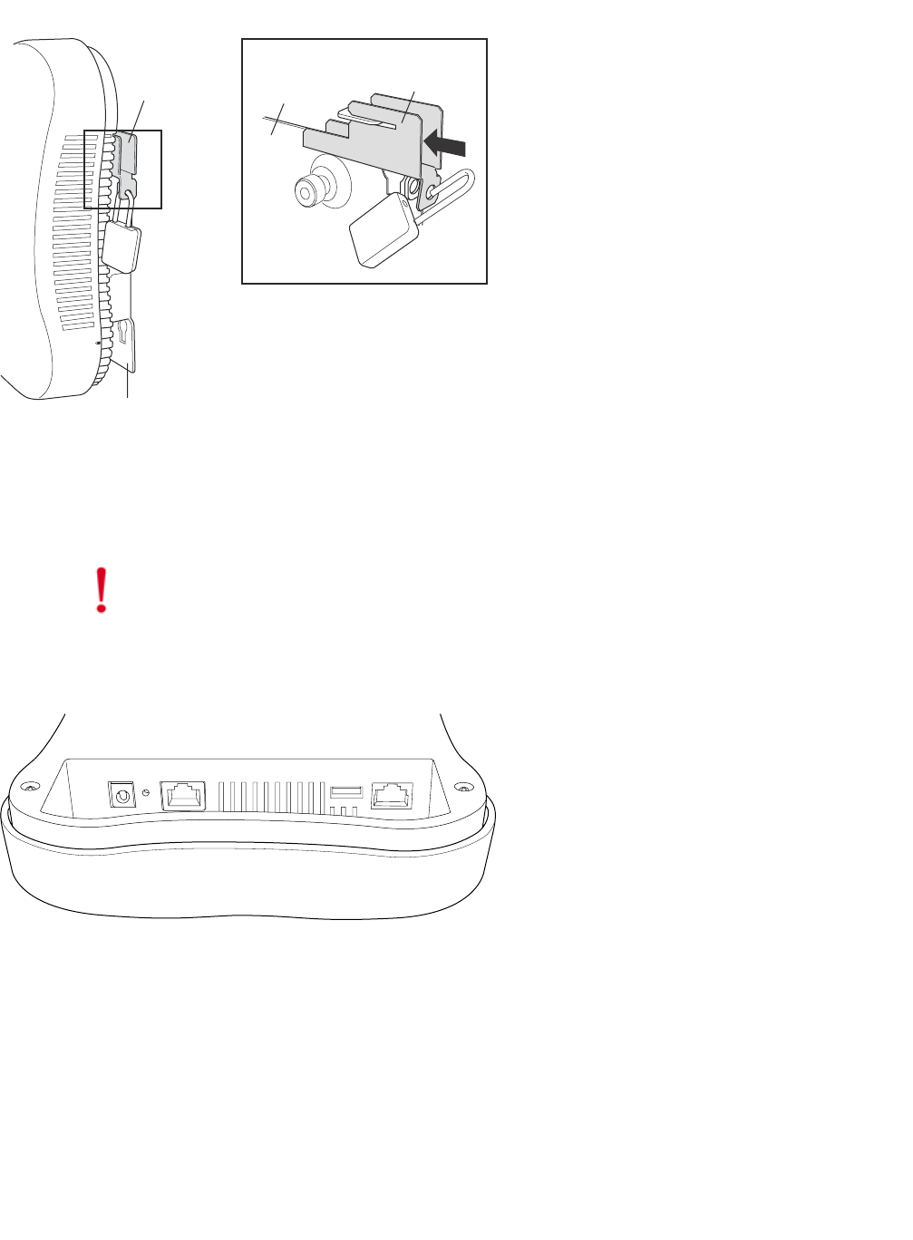
3. Attach the PoE Ethernet cable to the Ethernet port shown in Figure 37.
Figure 37: AP1000 Ethernet Port
4. Align the tabs on the wall bracket with the tabs on the wall and slide the unit down slightly. See
Figure 35.
Mount AP1000 on a Wall Using the Optional Locking Kit
The AP1000 locking wall mount kit (840-00052 ACC-MNT-AP1000-01)contains a wall bracket, screws,
and a locking key. To mount an AP1000 on sheetrock or wall studs with this kit, follow these steps:
1. Check to be sure that AP1000 is not locked by inserting the locking key into the Unlock mechanism
as shown below.
Figure 38: Unlock AP1000
Caution!
Be sure to connect the Ethernet cable to the Ethernet port. The cable can
mistakenly be plugged into the Console port; if you do this. the AP won’t power up.
00248
00253
Key
UNLOCK
10
64 Meru Access Point Installation Guide © 2010 Meru Networks, Inc.
Installing AP1000
AP1000 Beta Test
2. Attach AP1000 to the bracket as shown in Figure 39.
Figure 39: Attach AP1000 to Wall Bracket
3. Lock the AP1000 with the built-in locking mechanism as shown in Figure 40
Figure 40: Lock AP1000
4. Insert the locking key and apply a small suitcase lock as shown in Figure 41.
00251
Wall mount bracket
LOCK
Key
11
Installing AP1000
© 2010 Meru Networks, Inc. Installing AP1000 65
AP1000 Beta Test
Figure 41: AP1000 Locked to a Wall
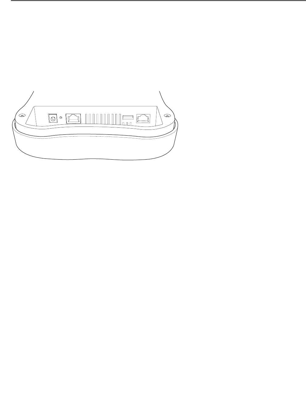
Set AP1000 on a Shelf
Set AP100 on any horizontal surface and then connect a PoE Ethernet cable.
Figure 42: AP1000 Ethernet Port on the Right
Mount AP1000 Above a Suspended Ceiling (Plenum)
AP1000 is not plenum rated and may only be mounted above the ceiling in a space that is not plenum,
such as a return airflow for air conditioning.
Caution!
Be sure to connect the Ethernet cable to the Ethernet port. The cable can
mistakenly be plugged into the Console port; if you do this. the AP won’t power up.
00248
12
66 Meru Access Point Installation Guide © 2010 Meru Networks, Inc.
Restoring AP1000 Settings
AP1000 Beta Test
Restoring AP1000 Settings
Trigger the Restore mechanism to return the AP1000 to the factory default settings. This overrides any
changes that have been made from the controllers. Note that this restore mechanism differs from the
ones on the other APs. Instead of a straight paper clip, you need to use a paper clip bent at a right
angle to push the mechanism trigger located on the inside. Access it through the small hole with the
bent paper clip. Press and hold the button for 10 seconds. After 10 seconds, the AP reboots and comes
back up with default settings.
Figure 43: AP1000 Ethernet Port
00248
13

Check AP1000 LEDs
© 2010 Meru Networks, Inc. Installing AP1000 67
AP1000 Beta Test
Check AP1000 LEDs
Figure 44: AP1000 Status LEDs
00249
LEDs
Status LAN
14

68 Meru Access Point Installation Guide © 2010 Meru Networks, Inc.
Check AP1000 LEDs
AP1000 Beta Test
The AP1000 has two LEDs, Status and LAN, as shown in Figure 44. If you want to change the appearance
of the LEDS, follow these steps:
1. From the controller, click Configuration > Devices > AP, and then select the AP.
2. Select one of these settings for the LED Mode setting:
—Normal: LEDs are as described below
—Node ID: Not supported in release 4.1
—Blink: Sets all LEDs flashing; this is useful to locate an AP
—Dark: Turns off all LEDs
3. Click OK.
LED Color State:
Status
(left LED)
off
AP is off - either there is no power or the LEDs are
set to Off on the controller. Check the LED setting
on the controller by clicking Configuration >
Devices > AP, selecting the AP and then checking
the setting for LED Mode.
cyan AP is booting stage 1.
green blinking AP is booting stage 2.
green/white alternating AP is discovering the controller.
green/blue alternating AP is downloading a configuration from the
controller.
slow blue blinking AP is online and enabled.
rapid blue blinking AP is online and enabled and there is activity on
one or both radios.
red/yellow alternating
Some AP failure occurred; check the controller for
more details about the alarm by clicking Monitor
> Alarms > Pending Alarms.
blue/yellow alternating
AP is online and enabled and one or both radios
are either scanning or an admin has taken the
radio(s) down.
LAN
(right LED)
green LAN link is up.
green blinking LAN link is up and some activity is taking place.
red Link has either failed or has been brought down.
alternating green/orange Link is experiencing receive errors.
15

Where to Go From Here
© 2010 Meru Networks, Inc. Installing AP1000 69
AP1000 Beta Test
Where to Go From Here
Now that the AP1000 is installed, go to the Meru System Director Getting Started Guide for instructions
on initializing the hardware. Return to this chapter to check the status of the LEDs once the WLAN is
operational; note that LED status is configurable, so the chart above may not apply to APs whose status
was reconfigured.
16