Meru Networks AP200 802.11 a/b/g Wireless Access Point User Manual AP Install
Meru Networks Inc. 802.11 a/b/g Wireless Access Point AP Install
Contents
- 1. User Manual
- 2. Users Manual
Users Manual

Meru Access Point
Installation Guide
Document Number: 880-00011-0006

ii :
Revision History
Copyright © Meru Networks, Inc., 2003–2004. All rights reserved.
Other names and brands may be claimed as the property of others.
Printed in USA.
Revision Date Revision
December 2004 0006
November 2004 0005
October 2004 0004
August 2004 0003
June 2004 0002
May 2004 0001
Contents iii
Contents
About This Guide . . . . . . . . . . . . . . . . . . . . . . . . . . . . . . ix
Audience . . . . . . . . . . . . . . . . . . . . . . . . . . . . . . . . ix
In This Guide . . . . . . . . . . . . . . . . . . . . . . . . . . . . . . ix
Other Sources of Information . . . . . . . . . . . . . . . . . . . . . . . . ix
Meru Publications . . . . . . . . . . . . . . . . . . . . . . . . . . . ix
External References . . . . . . . . . . . . . . . . . . . . . . . . . . x
Typographic Conventions . . . . . . . . . . . . . . . . . . . . . . . . . x
Contacting Meru . . . . . . . . . . . . . . . . . . . . . . . . . . . . . x
Customer Services and Support . . . . . . . . . . . . . . . . . . . . . . x
FCC Compliance . . . . . . . . . . . . . . . . . . . . . . . . . . . . . xi
Declaration of Conformity . . . . . . . . . . . . . . . . . . . . . . . . xi
Chapter 1
About Meru Access Points . . . . . . . . . . . . . . . . . . . . . . . . . 1
Meru Access Point Features . . . . . . . . . . . . . . . . . . . . . . . . . 1
Meru Access Point Models . . . . . . . . . . . . . . . . . . . . . . . . . 2
Chapter 2
Installing the AP100. . . . . . . . . . . . . . . . . . . . . . . . . . . . . 5
Safety Precautions . . . . . . . . . . . . . . . . . . . . . . . . . . . . 5
FCC Safety Compliance Statement . . . . . . . . . . . . . . . . . . . . 5
General Safety Guidelines . . . . . . . . . . . . . . . . . . . . . . . . 5
Warnings . . . . . . . . . . . . . . . . . . . . . . . . . . . . . . 6
Unpacking the Access Point. . . . . . . . . . . . . . . . . . . . . . . . . 7
Installation Requirements. . . . . . . . . . . . . . . . . . . . . . . . . . 7
Installing the Access Point . . . . . . . . . . . . . . . . . . . . . . . . . 9
Selecting a Location . . . . . . . . . . . . . . . . . . . . . . . . . . 9
Attaching the AP Antennas . . . . . . . . . . . . . . . . . . . . . . . 9
Mounting the Access Point. . . . . . . . . . . . . . . . . . . . . . . . 10
Checking LED Activity . . . . . . . . . . . . . . . . . . . . . . . . . . 14
AP100 Status LEDs . . . . . . . . . . . . . . . . . . . . . . . . . . 15
Chapter 3
Installing the AP200. . . . . . . . . . . . . . . . . . . . . . . . . . . . 17
Safety Precautions . . . . . . . . . . . . . . . . . . . . . . . . . . . . 17
FCC Safety Compliance Statement . . . . . . . . . . . . . . . . . . . . 17
General Safety Guidelines . . . . . . . . . . . . . . . . . . . . . . . . 17
Warnings . . . . . . . . . . . . . . . . . . . . . . . . . . . . . . 18
Unpacking the AP200 . . . . . . . . . . . . . . . . . . . . . . . . . . . 19
Installation Requirements. . . . . . . . . . . . . . . . . . . . . . . . . . 20
iv Meru Access Point Installation Guide
Installing the Access Point . . . . . . . . . . . . . . . . . . . . . . . . . 22
Selecting a Location . . . . . . . . . . . . . . . . . . . . . . . . . . 22
Attaching the AP200 Antennas . . . . . . . . . . . . . . . . . . . . . . 22
Mounting the Access Point . . . . . . . . . . . . . . . . . . . . . . . 23
Checking LED Activity . . . . . . . . . . . . . . . . . . . . . . . . . . 31
Ethernet Connector LEDs . . . . . . . . . . . . . . . . . . . . . . . . 31
AP200 Status LEDs . . . . . . . . . . . . . . . . . . . . . . . . . . 32
Appendix A
Specifications . . . . . . . . . . . . . . . . . . . . . . . . . . . . . . . 35
FCC Compliance . . . . . . . . . . . . . . . . . . . . . . . . . . . . . 35
Wireless Interface . . . . . . . . . . . . . . . . . . . . . . . . . . . . 36
Ethernet Interface . . . . . . . . . . . . . . . . . . . . . . . . . . . . 37
Physical . . . . . . . . . . . . . . . . . . . . . . . . . . . . . . . . 37
Appendix B
Declarations of Conformity and Regulatory Information . . . . . . . 39
Manufacturers Federal Communication Commission Declaration
of Conformity Statement . . . . . . . . . . . . . . . . . . . . . 39
Department of Communications—Canada . . . . . . . . . . . . . . . . . . . 40
Canadian Compliance Statement . . . . . . . . . . . . . . . . . . . . . 40
European Community, Switzerland, Norway, Iceland, and Liechtenstein . . . . . . . 41
Declaration of Conformity with Regard to the R&TTE Directive 1999/5/EC . . . . 41
Declaration of Conformity for RF Exposure . . . . . . . . . . . . . . . . . . 42
Guidelines for Operating Meru Access Points in Japan . . . . . . . . . . . . . . 43
Japanese Translation . . . . . . . . . . . . . . . . . . . . . . . . . . 43
English Translation . . . . . . . . . . . . . . . . . . . . . . . . . . 43
Appendix C
Translated Safety Warnings . . . . . . . . . . . . . . . . . . . . . . . 45
Dipole Antenna Installation Warning . . . . . . . . . . . . . . . . . . . . . 46
Explosive Device Proximity Warning. . . . . . . . . . . . . . . . . . . . . 47
Installation Warning . . . . . . . . . . . . . . . . . . . . . . . . . . . 48
Circuit Breaker (15A) Warning . . . . . . . . . . . . . . . . . . . . . . . 49
Appendix D
Channels . . . . . . . . . . . . . . . . . . . . . . . . . . . . . . . . . . 51
Channels . . . . . . . . . . . . . . . . . . . . . . . . . . . . . . . . 51
IEEE 802.11a. . . . . . . . . . . . . . . . . . . . . . . . . . . . . 51
IEEE 802.11b/g . . . . . . . . . . . . . . . . . . . . . . . . . . . . 52
List of Figures v
List of Figures
Figure 1 Meru Wireless LAN (WLAN) ..................................................................................1
Figure 2 AP200 .......................................................................................................................3
Figure 3 AP100 .......................................................................................................................3
Figure 4 AP100-P (Plenum Rated) .........................................................................................4
Figure 5 Attaching an Antenna to the AP100 .........................................................................10
Figure 6 Attaching the Ethernet Cable to the AP100 ..............................................................10
Figure 7 AP100-P Plenum Installation Items .........................................................................12
Figure 8 Light-Pipe Extender Attached to Bracket .................................................................12
Figure 9 AP100-P Installed Above Ceiling Tile .....................................................................14
Figure 10 RJ-45 LEDs ............................................................................................................14
Figure 11 Access Point 100 Status LEDs ...............................................................................15
Figure 12 AP200 Mounting Bracket .......................................................................................20
Figure 13 AP200 Antenna Connection ...................................................................................23
Figure 14 AP200 Connector Panel ..........................................................................................24
Figure 15 AP200 Bracket ........................................................................................................25
Figure 16 Aligning the AP200 with the Bracket .....................................................................26
Figure 17 Sliding the AP200 into the Bracket ........................................................................26
Figure 18 Mounting the AP200 to a Suspended Ceiling Rail .................................................27
Figure 19 Mounting the AP200 Above a Suspended Ceiling .................................................29
Figure 20 Box Hanger Mounting Bracket Holes ....................................................................29
Figure 21 Attaching the Mounting Bracket to the Box Hanger ..............................................30
Figure 22 RJ-45 LEDs ............................................................................................................31
Figure 23 AP200 Status LEDs ................................................................................................32
vi Meru Access Point Installation Guide
List of Tables vii
List of Tables
Table 1 AP100 Installation Items.......................................................................................... 8
Table 2 AP100 Installation Tools ......................................................................................... 8
Table 3 AP100 LED Descriptions ........................................................................................ 15
Table 4 AP100 Boot Status Information (LED 2) ................................................................ 16
Table 5 AP100-Controller Runtime Status Information (LED 2)......................................... 16
Table 6 AP200 Installation Items.......................................................................................... 21
Table 7 AP200 Installation Tools ......................................................................................... 21
Table 8 AP200 LED Descriptions ........................................................................................ 33
Table 9 AP200-Controller Status Information...................................................................... 33
Table 10 AP100 Wireless Interface Specifications............................................................... 36
Table 11 AP200 Wireless Interface Specifications............................................................... 36
Table 12 IEEE 802.11a Channels ......................................................................................... 51
Table 13 IEEE 802.11b/g Channels...................................................................................... 52
viii Meru Controller Installation Guide

Audience
About This Guide ix
About This Guide
This guide describes the features of the Meru Access Point family, which includes the AP200 and
AP100 models. This guide also includes the hardware installation for both access points. The term
access point is used interchangeably throughout this document to apply to either model when there
are no differences between the models.
Audience
This guide is intended for persons installing the Meru Access Point (AP).
In This Guide
This guide includes the following chapters:
zChapter 1, “About Meru Access Points”
zChapter 2, “Installing the AP100”
zChapter 3, “Installing the AP200”
Other Sources of Information
Additional information is available in the following Meru publications and external references.
Meru Publications
zMeru Wireless LAN System Release Notes
zMeru Wireless LAN System Getting Started Guide
zMeru Controller Installation Guide
zMeru Wireless LAN System Configuration Guide
zMeru Wireless LAN System Command Reference

xMeru Access Point Installation Guide
Typographic Conventions
External References
zStevens, W. R. 1994. TCP/IP Illustrated, Volume 1, The Protocols. Addison-Wesley, Reading,
Mass.
zGast, M.S. 2002. 802.11 Wireless Networks, The Definitive Guide. O’Reilly and Associates,
Sebastopol, Calif.
Typographic Conventions
This document uses the following typographic conventions to help you locate and identify
information:
Contacting Meru
You can visit Meru Networks on the Internet at this URL:
http://www.merunetworks.com
Click the Support menu button to view Meru Customer Services and Support information.
Customer Services and Support
For assistance, contact Meru Customer Services and Support 24 hours a day at 1-888-637-8952
(1-888-Meru-WLA(N)) or 1-408-215-5305. Email can be sent to support@merunetworks.com.
Meru Customer Services and Support provide end users and channel partners with the following:
zTelephone technical support
zSoftware update support
zSpare parts and repair service
Note:
Provides extra information, tips, and hints regarding the topic.
Caution!
Identifies important information about actions that could result in damage to or
loss of data, or could cause the application to behave in unexpected ways.
Warning!
Identifies critical information about actions that could result in equipment failure
or bodily harm.

FCC Compliance
About This Guide xi
RMA Procedures
Contact Meru Customer Services and Support for a Return Material Authorization (RMA) for any
Meru equipment.
Please have the following available when making a call:
zCompany and contact information
zEquipment model and serial numbers
zMeru software release and revision numbers (for example, 3.0.0-35)
zA description of the symptoms the problem is manifesting
zNetwork configuration
FCC Compliance
This device complies with part 15 of the FCC Rules. Operation is subject to the following two
conditions: (1) This device may not cause harmful interference, and (2) this device must accept any
interference received, including interference that may cause undesired operation.
Declaration of Conformity
The AP100 complies with the requirements of the Low Voltage Directive 73/23/EEC and the EMC
Directive 89/336/EEC by conforming to the following standards:
zSafety: EN 60950:1992 + A1, A2
zEMC: EN 55022, EN 50082-1
The AP200 complies the with following standards:
zRadio: EN 301.893
zEMC: EN 301.489-1, EN 489-17
zSafety: EN 60950
The following CE mark is affixed to the AP100 802.11b with 100 mW radios:
Caution!
Changes or modifications to the Meru Access Point that are not expressly approved by
Meru Networks will void your warranty and could void your authority to operate this equipment.
xii Meru Access Point Installation Guide
FCC Compliance
Note:
This equipment can be used in all EU and EFTA countries. Outdoor use may be restricted to
certain frequencies and/or may require a license for operation. For more details, contract Meru
Networks.
Note:
Combinations of power levels and antennas resulting in a radiated power level above 100
mW equivalent isotropic radiated power (EIRP) are considered as not compliant with the above
mentioned directive and are not allowed for use with the European community and other countries
that have adopted the European R&TTE directive 1999/5/EC or the CEPT recommendation Rec 70.03
or both.
The following CE mark is affixed to the AP200 802.11a with 40 mW radios:
Meru Access Point Features
About Meru Access Points 1
Chapter 1
About Meru Access Points
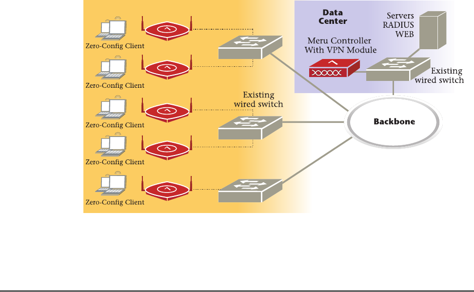
The Meru Access Point radio devices communicate with the Meru Controller and form the Wireless
LAN (WLAN). The Meru Controller and Access Points connect to the site’s wired LAN through
wired switches. Wireless clients associate with the Access Points as they roam throughout the WLAN.
As such, the Meru WLAN is an extension of the wired LAN, providing the wireless benefits of client
mobility, enhanced access, and dynamic network configuration.
Figure 1: Meru Wireless LAN (WLAN)
Meru Access Point Features
All Meru Access Points provide the following features:
zFive times more voice calls per Access Point
Meru Access Points use Over-The-Air QoS to provide fine-grained quality of service on a per-
application, per-user, and per-flow basis providing a robust platform for enterprise-quality voice,
plus streaming media and data applications. It provides both uplink and downlink QoS between
the client and the access point, which is then integrated into the wired QoS mechanisms to provide
Meru AP

2Meru Access Point Installation Guide
Meru Access Point Models
end-to-end QoS. Meru Access points deliver a 5-fold increase in voice carrying capacity from the
current 5-8 calls per access point to over 30 calls per Meru Access Point with no change to the
802.11 client.
zOver five times the scalability of alternate Access Points
Meru Access Points are unique in their ability to dramatically increase performance over alternate
APs, even as client density increases. Meru Access Points, can serve over 100 standard 802.11
active data and voice clients per access point, whereas today's systems are limited to about 10-15
data-only clients. This scalability allows corporations to plan for a wireless usage growth without
forklift upgrades to the WLAN infrastructure.
zZero-loss handoff means applications are not interrupted
Multiple Access Points can be aggregated into a Virtual AP, creating a single wireless network
with a wide coverage area that can encompass the entire enterprise campus and provide
unparalleled performance and manageability. This breakthrough technology works with any
standard 802.11 client device and enables application and security policy persistence while
roaming, without requiring the user to re-login or re-authenticate throughout the network coverage
area.
zEmbedded RF monitor for enhanced security
Traditional approaches to wireless security involve separate devices to monitor the air or legacy
APs, or access points that periodically become air monitors. Meru Access Points provide
continuous RF monitoring, as well as capture information about all devices that the AP can hear,
including clients associated with the access point. Meru WLAN Radar—a third generation rogue
AP detection software, provides rogue detection and suppression continuously and without any
interruption to the VPN sessions and time-sensitive voice applications that operate on the
converged wireless LAN in an enterprise. This constant monitoring enables enhanced security
with rogue device detection and prevention that is less disruptive and more cost effective than
traditional approaches.
Meru Access Point Models
The Meru Radio Access Point is available in two model families: the Access Point 200 and the Access
Point 100.
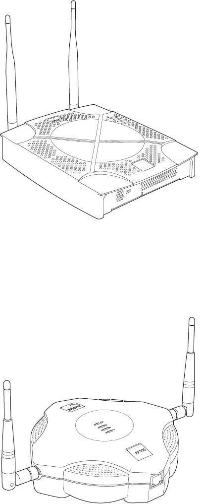
The Meru Dual Radio Access Point 200 family (AP200) provides models that conform to the
specifications provided by the IEEE 802.11a and 802.11g protocols and also provide backward
compatibility for the 802.11b protocol. The AP200 works with most standard WiFi clients. The
Access Point houses two radio devices: one supplying 802.11a, b, g, or bg service and the other
serving as an RF monitor to the Meru controller, providing real-time status of RF activity to optimize
the wireless network.
The AP200 is housed in a metal case with a plastic removable cover. As such, it can be used for
plenum installations when the plastic cover is removed.
Meru Access Point Models
About Meru Access Points 3
Figure 2: AP200
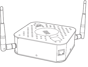
The Meru Access Point 100 family (referred to hereafter as the AP100, unless specifically referring
to the AP100-P) consists of the non-plenum AP100 and plenum-rated AP100-P. Both models that
conform to the specifications provided by the IEEE 802.11b protocol and work with all standard WiFi
clients. The AP100 also serves as an RF monitor to the Meru controller and provides real-time status
of RF activity to optimize the wireless network.
Figure 3: AP100
AP200
00109
00134
4Meru Access Point Installation Guide
Meru Access Point Models
Figure 4: AP100-P (Plenum Rated)
A
ccess Point 100-P
AP100
00117

Safety Precautions
Installing the AP100 5
Chapter 2
Installing the AP100
This chapter describes how to physically install the Meru AP100 and AP100-P. It contains the
following sections:
zSafety Precautions
zUnpacking the Access Point
zInstallation Requirements
zInstalling the Access Point
zChecking LED Activity
Safety Precautions
Follow the guidelines in this section to ensure proper operation and safe use of the access point.
FCC Safety Compliance Statement
The FCC with its action in ET Docket 96-8 has adopted a safety standard for human exposure to radio
frequency (RF) electromagnetic energy emitted by FCC certified equipment. When used with
approved Meru access point antennas, Meru AP100 products meet the uncontrolled environmental
limits found in OET-65 and ANSI C95.1, 1991. Proper installation of this radio according to the
instructions found in this manual will result in user exposure that is substantially below the FCC
recommended limits.
General Safety Guidelines
zDo not touch or move antenna(s) while the unit is transmitting or receiving.
zDo not hold any component containing a radio so that the antenna is very close to or touching any
exposed parts of the body, especially the face or eyes, while transmitting.
zThe use of wireless devices in hazardous locations is limited to the constraints posed by the local
codes, the national codes, and the safety directors of such environments.

6Installing the Meru Air Point 100
Safety Precautions
Warnings
Translated versions of the following safety warnings are provided in Appendix C.
Warning!
In order to comply with FCC radio frequency (RF) exposure limits, dipole antennas
should be located at a minimum of 7.9 inches (20 cm) or more from the body of all persons.
Warning!
Do not operate your wireless network device near unshielded blasting caps or in an
explosive environment unless the device has been modified to be especially qualified for such use.
Warning!
Do not work on the system or connect or disconnect cables during periods of lightning
activity.
Warning!
Read the installation instructions before you connect the system to its power source.
Warning!
This product relies on the building's installation for short-circuit (overcurrent) protection.
Ensure that a fuse or circuit breaker no larger than 120 VAC, 15A U.S. (240 VAC, 10A international)
is used on the phase conductors (all current-carrying conductors).
Warning!
Inside antennas must be positioned to observe minimum separation of 20 cm. (~ 8 in.)
from all users and bystanders. For the protection of personnel working in the vicinity of inside
(downlink) antennas, the following guidelines for minimum distances between the human body and
the antenna must be observed.
The installation of an INDOOR antenna must be such that, under normal conditions, all personnel
cannot come within 20 cm. (~ 8.0 in.) from any inside antenna. Exceeding this minimum separation
will ensure that the employee or bystander does not receive RF-exposure beyond the Maximum
Permissible Exposure according to FCC CFR 47, section 1.1310 i.e. limits for General
Population/Uncontrolled Exposure.
Warning!
The Outside antenna must be positioned to observe minimum separation of 120 cm.
(approximately 4 feet) from all users and bystanders. For the protection of personnel working in the
vicinity of outside (uplink) antennas, the following guidelines for minimum distances between the
human body and the antenna must be observed.
The installation of an OUTDOOR antenna must be such that, under normal conditions, all personnel
cannot come within 120 cm. (~ 4 ft.) from the outside antenna. In all installations, the antenna should
never be mounted such that the main beam is directed toward an area where workers or bystanders
may be present. Exceeding this minimum separation will ensure that the worker or bystander does not
receive RF-exposure beyond the Maximum Permissible Exposure according to FCC CFR 47, section
1.1310 i.e. limits for General Population/Uncontrolled Exposure.

Unpacking the Access Point
Installing the AP100 7
Unpacking the Access Point
The AP100 shipping package contains the following items:
zAccess point
zCD-ROM of Meru Wireless LAN System documentation
Confirm that the AP100-P shipping package contains the following items:
zAccess point
zOne mounting bracket
zLight-pipe extender
zTwo small mounting screws
zCD-ROM of Meru Wireless LAN System documentation
Installation Requirements
The following recommended mounting locations provide the best reception for the AP:
zOn a horizontal surface, such as a table or a desk
zOn a vertical surface, usually a wall
zUnderneath a horizontal surface, usually a ceiling
zAbove a ceiling tile (this installation is supported only for the AP100-P)
Suitable for use in environmental air space in accordance with the Section 300-22(c) of the
National Electric Code and Sections 2- 128.12 - 010 (3) and 12 - 100 of the Canadian Electrical
Code. Part 1. C22. 1. (For AP100-P model only.)
To complete this installation, you need the items listed in Table 1.

8Installing the Meru Air Point 100
Installation Requirements
Table 1: AP100 Installation Items
You need the tools listed in Table 2.
Table 2: AP100 Installation Tools
Installation Type Consumable Items Required
Horizontal mounting None
Vertical mounting over a wall stud zTwo #6 x 2" wood screws for a wood stud; or
zTwo #6 x 1½" metal screws for a metal stud
Vertical mounting on sheetrock zTwo #6 x 1" screws
zTwo #4-6 x 7/8" ribbed plastic wall anchors
Horizontal mounting below a ceiling zTwo #6 x 1" screws
zTwo #4-6 x 7/8" ribbed plastic wall anchors
Mounting above a ceiling tile
(AP100-P only)
zTwo #6 x 1" screws
zMounting bracket
zLight-pipe extender
Installation Type Tools Required
Horizontal mounting None
Vertical mounting over a wall stud zDrill
z1/8" drill bit
zScrewdriver
Vertical mounting on sheetrock zDrill
z3/16" drill bit
zScrewdriver
Horizontal mounting below a ceiling zDrill
z3/16" drill bit
zScrewdriver
Mounting above a ceiling tile
(AP100-P only)
zDrill
z1¼" hole saw
zScrewdriver

Installing the Access Point
Installing the AP100 9
Installing the Access Point
Selecting a Location
The AP requires a location that meets the following:
zRelatively unobstructed access to the stations the AP serves
zPower over Ethernet (PoE) connection to the network switch servicing the controller
APs obtain their power from 802.3af standard Power over Ethernet (PoE). The power can be supplied
by a PoE-compatible network switch or PoE power injector installed between the switch and the AP.
The Power LED on the AP100 (LED furthest from the RJ-45 connector) displays green if power is
supplied correctly to the AP.
Select a location with minimal physical obstructions between the AP and the wireless stations. In an
office with cubicles, mounting the APs on the ceiling or the wall near the ceiling provides the least
obstructed communications path.
Most installations receive the best coverage using the following guidelines:
zFor high throughput, place APs approximately 60 feet apart in a grid pattern.
zFor adequate coverage, place AP100s approximately 200 feet apart.
zInstall APs toward the center of the building.
zDo not install APs near metal objects, such as heating ducts, metal doors, or electric service
panels.
zRelative to the ground, orient the antenna up or down, not sideways.
Attaching the AP Antennas
Attach the antennas to the connectors on the AP100 (see Figure 5). Rotate the knurled ring at the base
of the antenna clockwise to attach the antenna, as shown in the following figure. The ring should be
finger-tight.
Note:
The previous guidelines are general guidelines. Each site has its own unique environment.
Place access points accordingly.
10 Installing the Meru Air Point 100
Installing the Access Point
Figure 5: Attaching an Antenna to the AP100
Mounting the Access Point
You can mount the access point in the following ways:
zHorizontally, as described in the “Horizontal Mounting” section.
zVertically, as described in the “Vertical Mounting” section.
zBelow a ceiling, as described in the “Mounting Below a Ceiling” section.
zAbove a ceiling tile, as described in the “Mounting Above a Suspended Ceiling” section.
Horizontal Mounting
To horizontally mount an AP100:
1. Place the AP flat on the horizontal surface.
2. For each antenna, loosen the knurled ring at the base of the antenna (see Figure 5), point the
antenna straight up, then retighten the ring.
3. Connect the PoE 100BaseT Ethernet cable, as shown in Figure 6.
Figure 6: Attaching the Ethernet Cable to the AP100
Antenna
Turn clockwise
to tighten
Access Point 100
0
0135
Caution!
When changing the orientation of the antennas, be sure to slightly loosen the knurled ring
before moving the antenna. Retighten the ring afterward. Otherwise, you might damage the internal
cabling in the AP.
Ethernet cable
0
0128

Installing the Access Point
Installing the AP100 11
Vertical Mounting
To vertically mount an AP100:
1. Mark the location for the two AP mounting screws. They must be 4 ½ inches apart, center-to-
center, one above the other. If you are not using plastic wall anchors, you must center the
mounting screws on a wall stud. If you do not center the mounting screws on a wall stud, you must
use plastic wall anchors.
2. Drill holes at the locations you marked:
—3/16-inch holes if you are using plastic anchors
—1/8-inch holes if you are using only the screws
3. If you are using plastic anchors, install them in the holes.
4. Screw in the screws most of the way, so that the screw head is about 1/16 of an inch from the wall.
5. Mount the AP on the screws, placing the circular portion of the keyhole mounts over the screw
heads and sliding the AP down.
6. For external antennas, loosen the knurled ring at the base of each antenna (see Figure 5), point
the antenna straight up, then retighten the ring.
7. Connect the PoE 100BaseT Ethernet cable (see Figure 6).
Mounting Below a Ceiling
To mount an access point below a ceiling:
1. Mark the location of the two mounting screws. They must be 4 ½ inches apart, center-to-center.
2. Drill holes at the locations you marked:
—3/16-inch holes if you are using plastic anchors
—1/8-inch holes if you are using only the screws
3. If you are using plastic anchors, install them in the holes.
4. Screw in the screws most of the way, so that the screw head is about 1/16 of an inch from the wall.
5. Mount the AP to the wall screws by placing the circular portion of the keyhole mounts over the
screw heads and sliding the AP down.
6. For each antenna, loosen the knurled ring at the base of the antenna (see Figure 5), point the
antenna straight down, then retighten the ring.
7. Connect the PoE 100BaseT Ethernet cable (see Figure 6).
Mounting Above a Suspended Ceiling
The AP100-P meets the requirements for fire resistance and low smoke-generating characteristics
required by Section 300-22(C) of the National Electrical Code (NEC) for installation in a building’s
environmental air space.
Note:
Only the Meru AP100-P, enclosed in a plenum-rated metal case, can be installed above
ceiling tiles. The Meru AP100 enclosed in a plastic case, must be installed below ceiling tiles.
12 Installing the Meru Air Point 100
Installing the Access Point
Figure 7: AP100-P Plenum Installation Items
To mount the AP100-P above a suspended ceiling:
1. Remove the ceiling tile where the AP100-P will be located.
2. Confirm that there is at least 6 inches of space above the ceiling tile to accommodate the AP
antennas. If there is insulation above the ceiling tile, clear it for at least three inches to the side
and three inches above the AP100-P.
3. Cut a hole in the tile, 1¼ inches in diameter, for the AP100-P light-pipe extender. The hole should
be at least 6 inches from the edge of the tile.
4. Insert the light-pipe extender into the tile hole, with the 2-inch flange on the appearance side of
the ceiling tile. Refer to Figure 8 for mounting bracket placement orientation, and invert the
extender.
Figure 8: Light-Pipe Extender Attached to Bracket
5. Attach the mounting bracket to the light-pipe extender, with the two small pins on the light-pipe
extender fitting into the small holes on the mounting bracket and the two hooked tabs fitting into
the two notches in the mounting bracket hole. Note that the tabs are different widths and the wide
tab fits only into the wide notch. Press the tabs in towards each other to clear the edges of the
notch. They lock in place.
Mounting bracket
Light pipe
Access Point 100-P
AP100
00116
Light pipe
00120
Installing the Access Point
Installing the AP100 13
6. Slide the AP100-P into the mounting bracket. Slide the bracket’s feet over the two feet of the
AP100-P closest to the keyhole mounts.
7. Attach the mounting bracket to the ceiling tile, using two #6 screws.
8. Position the small holes on the bracket over the small holes on the back of the AP100-P. Use two
screws supplied to attach the bracket to the AP100-P.
9. For each antenna, loosen the knurled ring at the base of the antenna (see Figure 5), point the
antenna straight up, then retighten the ring.
10. Return the ceiling tile to the ceiling, but leave the tile loose.
11. Connect the PoE 100BaseT Ethernet cable to the AP100-P (see Figure 6).
00118
00119
14 Installing the Meru Air Point 100
Checking LED Activity
12. If needed, reposition the antennas. Be sure to loosen the ring at the base of the antenna before
repositioning, and retighten after.
13. Replace the ceiling tile in the ceiling brackets.
The AP100-P, with mounting bracket and light-pipe extender, installed above a ceiling tile is shown
in Figure 9:
Figure 9: AP100-P Installed Above Ceiling Tile
Checking LED Activity
After the AP100 is connected, the LEDs near the RJ-45 connector should light, as shown in Figure 10.
Figure 10: RJ-45 LEDs
The green LED on the left blinks if any Ethernet activity is taking place. If there is no Ethernet activity,
the LED is off. The LED on the right is solid yellow if an Ethernet link is present. If no Ethernet link
is present or connectivity is lost, the LED is off.
M
ounting bracket
A
ccess Point
S
ide view
C
eiling tile
Light pipe extender
00121
Ethernet activity
Link present
00129
Checking LED Activity
Installing the AP100 15
AP100 Status LEDs
Four status LEDs on the face of the AP100 also light, as shown in Figure 11.
.
Figure 11: Access Point 100 Status LEDs
The Power LED, farthest from the Meru logo, displays green when power is on.
The functions of the LEDs are described in Table 3.
Table 3: AP100 LED Descriptions
When the AP is first connected to the controller and any time the access point is rebooted thereafter,
the AP initializes with and then is programmed by the controller. LED 2 gives the status of the boot
cycle. Table 4 lists typical successful boot information.
LED Function
LED1 Green: Presence of power
LED2 Boot status (see Table 4)
LED3 Green: Wireless transmit activity (TX)
LED4 Green: Wireless receive activity (RX)
Power
Boot status
Wireless TX
Wireless RX
00136

16 Installing the Meru Air Point 100
Checking LED Activity
Table 4: AP100 Boot Status Information (LED 2)
After the boot is complete, LED 2 cycles to show the access point-controller runtime status. These
LED states are shown in Table 5.
Table 5: AP100-Controller Runtime Status Information (LED 2)
AP100 LED activity Boot Stage
Red, one second Power on
Black, five seconds Access point self-test
Yellow/Green, alternating for five seconds Downloading image from the controller
Red, for one quarter second Download complete
Varies Operating status indicated by Table 5
State Interpretation AP100 LED Cycle
Initializing In the process of initializing. The AP is con-
nected but not authenticated.
Green/Yellow/Red/
Green/Red/
Green/Yellow/Red/
Green/Red
Connected Normal operation without security Green/Off/Green/Off
Authenticated Normal operation with security Green blink, blink,
blink; Green long blink,
Green long blink
Initialization
failed
Configuration was downloaded, but AP ini-
tialization failed. AP automatically reboots.
Red/Off/Red/Off
Disconnected Access point was once connected to a con-
troller and configured by the controller, but
can no longer find that controller
Green/Yellow/
Green/Yellow
Standalone Access point is operating in a standalone
mode
Green/Long Yellow/
Long Green/Yellow/
Green/Long Yellow/
Long Green/Yellow
Downloading Downloading image or configuration from
the controller
Off/Yellow/Off/Yellow/
Off/Green/Off/Green/
Off/Yellow/Off/Yellow/
Off/Green/Off/Green
Error State Access point is in an error state. Call Meru
technical support
Long Red/Off/Yellow/
Long Off/
Long Red/Off/ Yellow/
Long Off

Safety Precautions
Installing the AP200 17
Chapter 3
Installing the AP200
This chapter describes how to physically install the Meru AP200. It contains the following sections:
zSafety Precautions
zUnpacking the AP200
zInstallation Requirements
zInstalling the Access Point
zChecking LED Activity
Safety Precautions
Follow the guidelines in this section to ensure proper operation and safe use of the access point.
FCC Safety Compliance Statement
The FCC with its action in ET Docket 96-8 has adopted a safety standard for human exposure to radio
frequency (RF) electromagnetic energy emitted by FCC certified equipment. When used with
approved Meru access point antennas, Meru AP200 products meet the uncontrolled environmental
limits found in OET-65 and ANSI C95.1, 1991. Proper installation of this radio according to the
instructions found in this manual will result in user exposure that is substantially below the FCC
recommended limits.
General Safety Guidelines
zDo not touch or move antenna(s) while the unit is transmitting or receiving.
zDo not hold any component containing a radio so that the antenna is very close to or touching any
exposed parts of the body, especially the face or eyes, while transmitting.
zThe use of wireless devices in hazardous locations is limited to the constraints posed by the local
codes, the national codes, and the safety directors of such environments.

18 Meru Access Point Installation Guide
Safety Precautions
Warnings
Translated versions of the following safety warnings are provided in Appendix C.
Warning!
In order to comply with FCC radio frequency (RF) exposure limits, dipole antennas
should be located at a minimum of 7.9 inches (20 cm) or more from the body of all persons.
Warning!
Do not operate your wireless network device near unshielded blasting caps or in an
explosive environment unless the device has been modified to be especially qualified for such use.
Warning!
Do not work on the system or connect or disconnect cables during periods of lightning
activity.
Warning!
Read the installation instructions before you connect the system to its power source.
Warning!
This product relies on the building's installation for short-circuit (overcurrent) protection.
Ensure that a fuse or circuit breaker no larger than 120 VAC, 15A U.S. (240 VAC, 10A international)
is used on the phase conductors (all current-carrying conductors).
Warning!
Inside antennas must be positioned to observe minimum separation of 20 cm. (~ 8 in.)
from all users and bystanders. For the protection of personnel working in the vicinity of inside
(downlink) antennas, the following guidelines for minimum distances between the human body and
the antenna must be observed.
The installation of an INDOOR antenna must be such that, under normal conditions, all personnel
cannot come within 20 cm. (~ 8.0 in.) from any inside antenna. Exceeding this minimum separation
will ensure that the employee or bystander does not receive RF-exposure beyond the Maximum
Permissible Exposure according to FCC CFR 47, section 1.1310 i.e. limits for General
Population/Uncontrolled Exposure.
Warning!
The Outside antenna must be positioned to observe minimum separation of 120 cm.
(approximately 4 feet) from all users and bystanders. For the protection of personnel working in the
vicinity of outside (uplink) antennas, the following guidelines for minimum distances between the
human body and the antenna must be observed.
The installation of an OUTDOOR antenna must be such that, under normal conditions, all personnel
cannot come within 120 cm. (~ 4 ft.) from the outside antenna. In all installations, the antenna should
never be mounted such that the main beam is directed toward an area where workers or bystanders
may be present. Exceeding this minimum separation will ensure that the worker or bystander does not
receive RF-exposure beyond the Maximum Permissible Exposure according to FCC CFR 47, section
1.1310 i.e. limits for General Population/Uncontrolled Exposure.

Unpacking the AP200
Installing the AP200 19
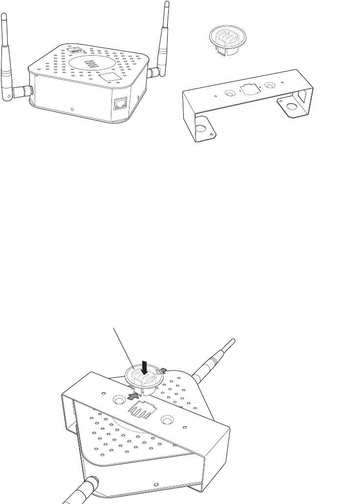
Unpacking the AP200
The AP200 ships with a mounting bracket and mounting hardware for standard wall mounting.
Optional mounting kits are available for mounting the AP200 above or below a hanging ceiling. The
AP200 mounting studs are placed so they can be used with brackets supplied by other vendors or to
replace an AP100.
Note:
The AP200 has a security cable slot so you can secure the AP200 with a standard security
cable, such as those used to secure laptop computers.
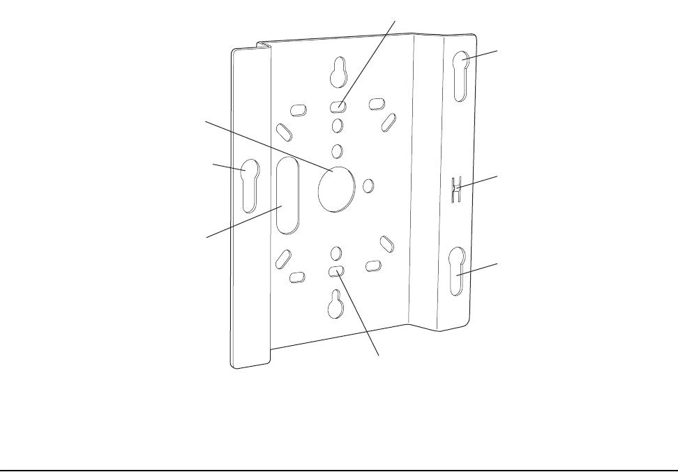
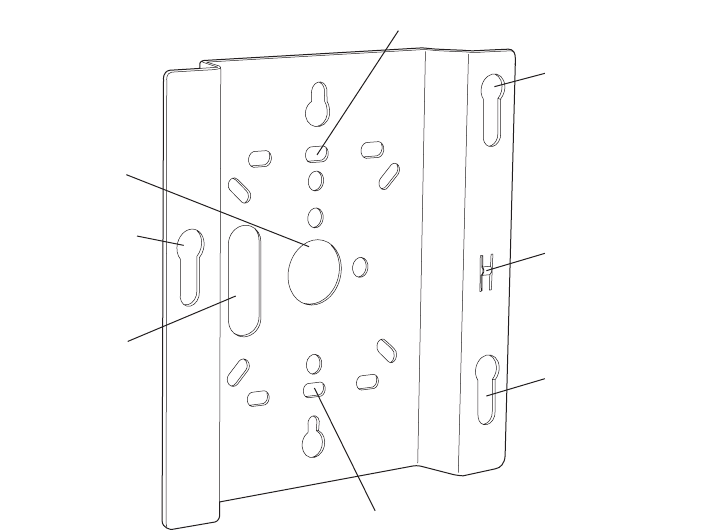
An array of holes on the mounting bracket (see Figure 12) allow it to be mounted on the wall and over
junction boxes or molly bolts. There are also holes for passing the PoE Ethernet or external power
supply cable through the bracket if the bracket is mounted on a junction box or over the ceiling T-bar
box hanger.
Confirm that the AP200 shipping package contains the following items:
zAccess point
zMounting bracket with two mounting screws
zCD-ROM of Meru Wireless LAN System documentation
zOptional suspended ceiling mounting hardware kit
zOptional T-bar box hanger hardware kit for mounting above a suspended ceiling
zOptional 3.3V DC external power supply connector
20 Meru Access Point Installation Guide
Installation Requirements
Figure 12: AP200 Mounting Bracket
Installation Requirements
The following recommended mounting locations provide the best reception for the AP200:
zOn a horizontal surface, such as a table or a desk
zOn a vertical surface, usually a wall
zBelow a hanging ceiling
zAbove a hanging ceiling tiles (this installation is supported only for the AP200 with the plastic
enclosure removed)
Suitable for use in environmental air space in accordance with the Section 300-22(c) of the
National Electric Code and Sections 2- 128.12 - 010 (3) and 12 - 100 of the Canadian Electrical
Code. Part 1. C22. 1. (For AP200 with plastic enclosure removed.)
To complete this installation, you need the items listed in Table 6.
Access point mount
Ceiling mount hole
Ceiling mount hole
A
ccess point mount
Access point mount
Locking detent
W
all cable access
S
uspended ceiling
c
able access
00100

Installation Requirements
Installing the AP200 21
Table 6: AP200 Installation Items
You need the tools listed in Table 7.
Table 7: AP200 Installation Tools
Installation Type Consumable Items Required
Horizontal mounting None
Vertical mounting over a wall stud zTwo #6 x 2" wood screws for a wood stud; or
zTwo #6 x 1½" metal screws for a metal stud
zMounting bracket
Vertical mounting on sheetrock zTwo #6 x 1" screws
zTwo #4-6 x 7/8" ribbed plastic wall anchors
zMounting bracket
Horizontal mounting below a hanging
ceiling
zTwo caddy fasteners
zTwo plastic spacers
zTwo keps nuts (with attached lock washer)
zMounting bracket
Mounting above a ceiling tile (AP200
metal enclosure only)
zTwo T-rail clips
zOne T-box hanger
zOne bracket mounting clip
zMounting bracket
Installation Type Tools Required
Horizontal mounting None
Vertical mounting over a wall stud zDrill
z1/8"drill bit
zScrewdriver
Vertical mounting on sheetrock zDrill
z3/16" drill bit
zScrewdriver

22 Meru Access Point Installation Guide
Installing the Access Point
Installing the Access Point
Selecting a Location
The AP200 requires a location that meets the following:
zRelatively unobstructed access to the stations the AP serves
zPower over Ethernet (PoE) connection to the network switch servicing the controller or optional
nearby power supply for external power supply connector
APs can obtain their power from 802.3af standard Power over Ethernet (PoE) or external power
supply. For PoE, the power can be supplied by a PoE-compatible network switch or PoE power
injector installed between the switch and the AP200. For an external power supply connection, ensure
the power source is near to where the AP200 will be mounted.
Select a location with minimal physical obstructions between the AP and the wireless stations. In an
office with cubicles, mounting the APs below a hanging ceiling or the wall near the ceiling provides
the least obstructed communications path.
Most installations receive the best coverage using the following guidelines:
Install APs toward the center of the building.
zDo not install APs near metal objects, such as heating ducts, metal doors, or electric service
panels.
zRelative to the ground, orient the antenna up or down, not sideways.
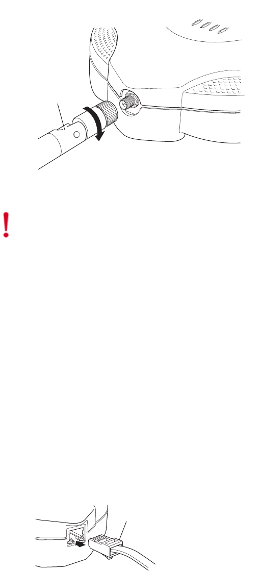
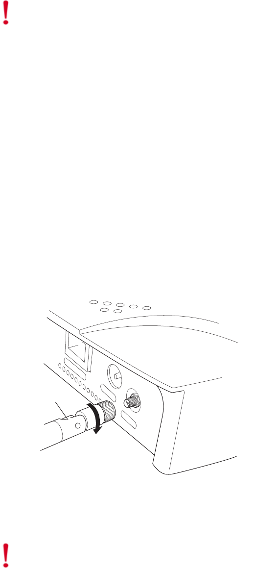
Attaching the AP200 Antennas
If the AP200 does not have external antennas, attach the antennas to the connectors on the AP200 (see
Figure 13). Rotate the knurled ring at the base of the antenna clockwise to attach the antenna. The
ring should be finger-tight.
Horizontal mounting below a hanging
ceiling
zScrewdriver
zWrench or pliers
Mounting above a hanging ceiling
(AP200 metal enclosure only)
zWrench or pliers
zScrewdriver
Installation Type Tools Required
Note:
The previous guidelines are general guidelines. Each site has its own unique environment.
Place access points accordingly.
Installing the Access Point
Installing the AP200 23
Mounting the Access Point
You can mount an AP200 in the following ways:
zHorizontally, as described in the “Horizontal Mounting” section.
zVertically, as described in the “Vertical Mounting” section.
zBelow a hanging ceiling, as described in the “Mounting Below a Suspended Ceiling” section.
zAbove a tiled hanging ceiling, as described in the “Mounting Above a Suspended Ceiling”
section.
Horizontal Mounting
To horizontally mount an AP200:
1. Place the AP200 flat on the horizontal surface.
2. For each antenna, loosen the knurled ring at the base of the antenna (see Figure 13), point the
antenna straight up, then retighten the ring.
Figure 13: AP200 Antenna Connection
3. Connect the PoE 100BaseT Ethernet cable to the 100/1000 Ethernet connector, shown in
Figure 14.
Caution!
When changing the orientation of the antennas, be sure to slightly loosen the knurled ring
before moving the antenna. Retighten the ring afterward. Otherwise, you might damage the internal
cabling in the AP.
Turn clockwise
to tighten
A
ntenna
Access Point 200
ETHERNET
3.3 VDC ANT 2
00110
Caution!
Be sure to connect the Ethernet cable to the Ethernet port; the cable can mistakenly be
plugged into the Console port.
24 Meru Access Point Installation Guide
Installing the Access Point
4. If using a separate power supply, connect the power cable to the power inlet connector shown in
Figure 14.
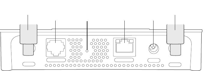
Figure 14: AP200 Connector Panel
Vertical Mounting
To vertically mount an AP:
1. Using the bracket holes as a template, mark the location on the wall for the two AP bracket
mounting screws. They are placed 4 ½ inches apart, center-to-center, one above the other. If you
are not using plastic wall anchors, you must center the mounting screws on a wall stud. If you do
not center the mounting screws on a wall stud, you must use plastic wall anchors.
CONSOLE
ANT 1 ANT 2
3.3 VDC
ETHERNET
0
0108
100/1000
Ethernet
(Reserved)
Console
port
Antenna 1 Antenna 2
Power
inlet
Reset
(push to restore
default settings)
Installing the Access Point
Installing the AP200 25
Figure 15: AP200 Bracket
2. Drill holes at the locations you marked:
—3/16-inch holes if you are using plastic anchors
—1/8-inch holes if you are using only the screws
3. If you are using plastic anchors, install them in the holes.
4. Screw in the screws most of the way, so that the screw head is about 1/16 of an inch from the wall.
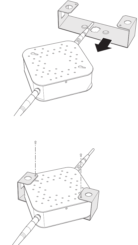
5. Mount the bracket on the screws, placing the circular portion of the keyhole mounts over the
screw heads and sliding the bracket down.
6. Tighten the screws to secure the bracket.
7. Align the AP200 mounting posts over the circular portion of the keyhole mounts, push the AP in
and slide the AP down until it engages with the locking detents. You should hear it snap in place.
Access point mount
Ceiling mount hole
Ceiling mount hole
A
ccess point mount
Access point mount
Locking detent
W
all cable access
S
uspended ceiling
c
able access
00100
26 Meru Access Point Installation Guide
Installing the Access Point
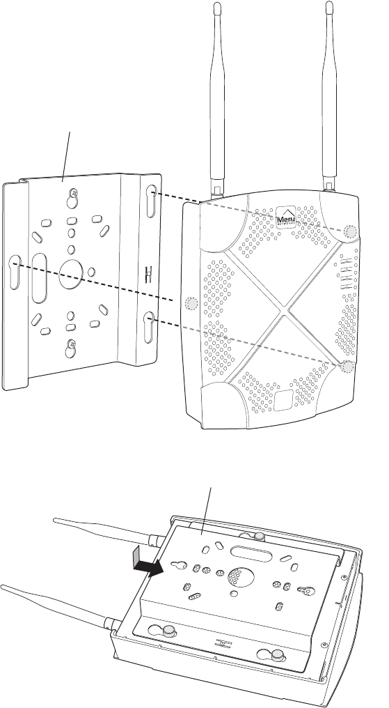
Figure 16: Aligning the AP200 with the Bracket
Figure 17: Sliding the AP200 into the Bracket
8. For external antennas, loosen the knurled ring at the base of each antenna (see Figure 13), point
the antenna straight up, then retighten the ring.
00115
Mounting bracket attached to wall
AP200
00112
Mounting bracket
Installing the Access Point
Installing the AP200 27
9. Connect the PoE 100BaseT Ethernet cable or 100BaseT Ethernet cable to the 100/1000 Ethernet
connector shown in Figure 14.
10. Optionally connect the external power source connector to the AP power inlet connector (shown
in Figure 14) and to the power source.
Mounting Below a Suspended Ceiling
The optional suspended ceiling mounting kit allows the AP200 mounting bracket to attach to
suspended ceiling T-rails (see Figure 18).
Note:
To comply with NEC code, attach a grounding wire to any of the screws used to attach the
AP200 to the mounting bracket.
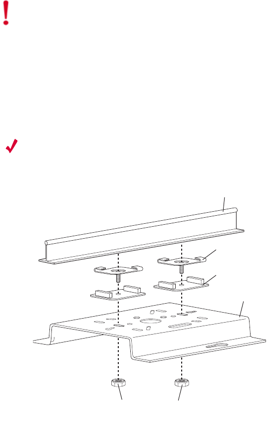
Figure 18: Mounting the AP200 to a Suspended Ceiling Rail
To mount an AP200 below a suspended ceiling:
1. Determine the location on the ceiling rail where the AP will be mounted and remove the ceiling
tiles.
2. Place each of the two caddy fasteners on the ceiling T-rail and twist to attach to the rail.
3. Adjust the distance between the caddy fasteners by using the mounting bracket holes as a guide.
4. Tighten the caddy fasteners in place using a standard screwdriver. Do not overtighten.
Caution!
Be sure to connect the Ethernet cable to the Ethernet port; the cable can mistakenly be
plugged into the Console port.
Suspended ceiling T-rail
Mounting bracke
t
Keps nuts with attached
locking washer
Caddy fastener(
s)
Plastic spacer(s
)
00102

28 Meru Access Point Installation Guide
Installing the Access Point
5. Place each spacer on the caddy fastener stud. The spacer legs should contact the ceiling
T-rail.
6. Align the mounting bracket keyholes with the caddy fastener studs and slide the AP200 to the
narrow end of the hole.
7. Attach a keps nut to each caddy fastener stud and hand tighten. Do not overtighten.
8. Align the AP200 mounting posts over the circular portion of the keyhole mounts, push the AP in
and slide the AP down until it engages with the locking detents (see Figure 17). You should hear
it snap in place.
9. For each antenna, loosen the knurled ring at the base of the antenna (see Figure 13), point the
antenna straight down, then retighten the ring.
10. Connect the PoE 100BaseT Ethernet cable to the 100/1000 Ethernet connector (see Figure 14).
11. Optionally connect the external power supply cable to the AP power inlet (see Figure 14) and to
the power source.
Mounting Above a Suspended Ceiling
The optional T-bar box hanger mounting kit allows the AP200 to be mounted above suspended ceiling
T-rails (see Figure 19). The installation attaches the T-bar box hanger to the ceiling rails using clips.
The AP200 attaches to the mounting bracket that is attached to the T-bar box hanger.
The AP200 antennas should point straight down for this type of installation. You may need to modify
thicker tiles to support this installation.
Caution!
Be sure to connect the Ethernet cable to the Ethernet port; the cable can mistakenly be
plugged into the Console port.
Note:
The AP200 with the metal enclosure exposed meets the requirements for fire resistance and
low smoke-generating characteristics required by Section 300-22(C) of the National Electrical Code
(NEC) for installation in a building’s environmental air space. You must remove the plastic enclosure
to reveal the plenum-rated AP200 metal case for installations above a suspended ceiling.
Additionally, you must use Ethernet cable that meets the requirements for operating in environmental
air space (in accordance with Section 300-22(C) of the NEC).
Installing the Access Point
Installing the AP200 29
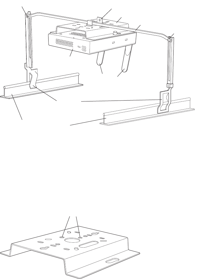
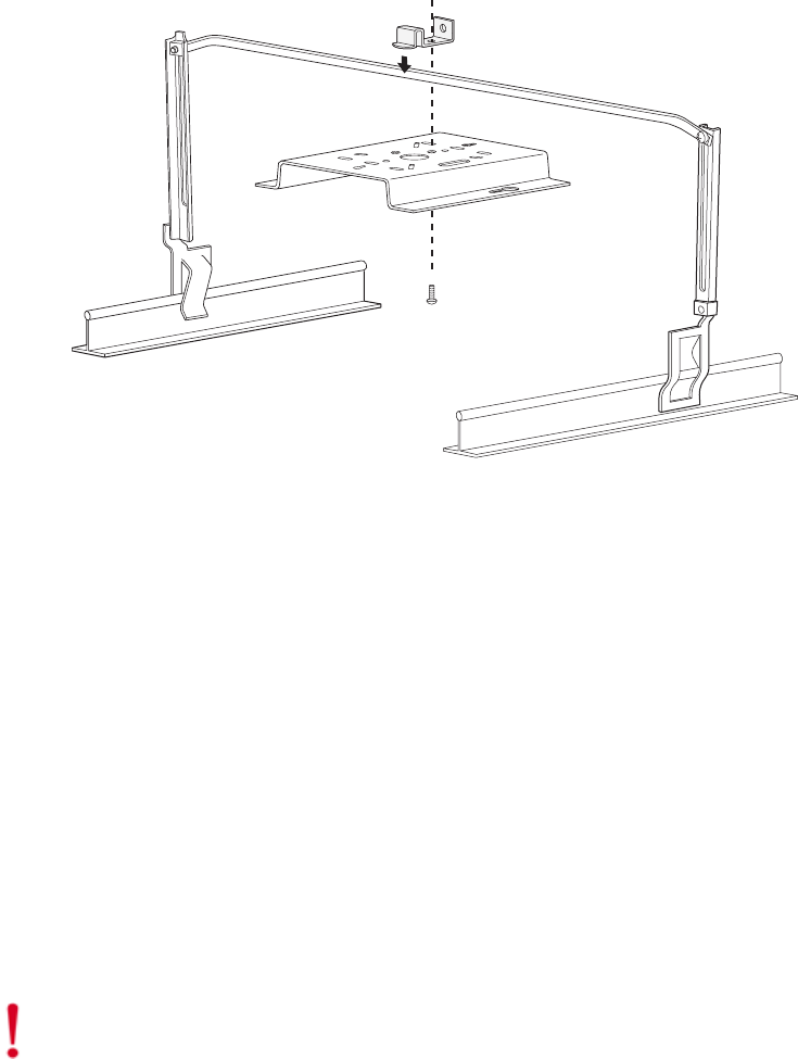
Figure 19: Mounting the AP200 Above a Suspended Ceiling
To mount an AP200 above suspended ceiling rails:
1. Determine the location on the ceiling rails where the AP will be mounted and remove the ceiling
tile.
2. Unpack the T-bar hanger kit and unfold the legs of the T-bar hanger.
3. Locate the bracket mounting clip holes on the mounting bracket (see Figure 20). One hole
attaches the bracket perpendicular to the box hanger. The other mounts the bracket parallel to the
box hanger.
Figure 20: Box Hanger Mounting Bracket Holes
4. Attach the U-joint of the clip to the T-bar and snap in place (see Figure 21).
Bracket mounting clip
Mounting bracket
T-bar hanger Height adjustment scre
w
Height adjustment screw
Suspended ceiling T-rail
T-rail clips
Antennas
Access Point 200
00103
Mounting bracket holes
00101
30 Meru Access Point Installation Guide
Installing the Access Point
.
Figure 21: Attaching the Mounting Bracket to the Box Hanger
5. Pass the long end clip through the large center hole to the underside of the the mounting bracket
clip and then attach the bracket to the clip using the supplied screw (see Figure 21 for
orientation).
6. Hold the AP200 next to the mounting bracket to estimate the height of the T-bar box hanger to
provide enough clearance for the external antennas, which should be pointing down.
7. Adjust the height of the box hanger using the height adjusting screws (see Figure 18).
8. Clip the box hanger T-rail clips to the ceiling rails, making sure they are securely attached.
9. Connect a drop wire to a building structural element and through the hold provided in the bracket
mounting clip. The U.S. National Electrical Safety Code requires this additional support.
10. Connect the posts of the AP200 to the three keyholes of the mounting bracket and slide into the
keyhole (see Figure 17), ensuring the locking detent is engaged. You will hear a click.
11. For each antenna, loosen the knurled ring at the base of the antenna (see Figure 13), point the
antenna down, then retighten the ring.
12. Connect the Ethernet cable to the AP200 (see Figure 14).
13. Check that the AP200 is operating correctly before replacing the ceiling tile to the ceiling. Verify
correct operating using the LEDs, as shown in the next section.
00104
Caution!
Be sure to connect the Ethernet cable to the Ethernet port; the cable can mistakenly be
plugged into the Console port.
Checking LED Activity
Installing the AP200 31
Checking LED Activity
Access point status LEDs are provided on the Ethernet connector and on the face of the AP200.
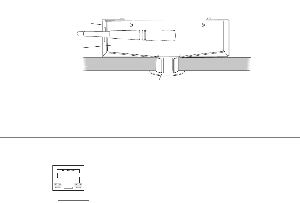
Ethernet Connector LEDs
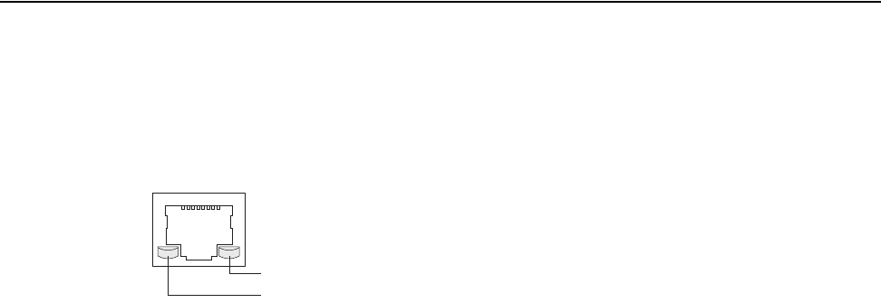
After the AP200 is connected, the LEDs near the RJ-45 connector should light, as shown in Figure 22.
Figure 22: RJ-45 LEDs
The green LED on the left blinks if any Ethernet activity is taking place. If there is no Ethernet activity,
the LED is off. The LED on the right is solid yellow if an Ethernet link is present. If no Ethernet link
is present or connectivity is lost, the LED is off.
Ethernet activity
Link present
00129
32 Meru Access Point Installation Guide
Checking LED Activity
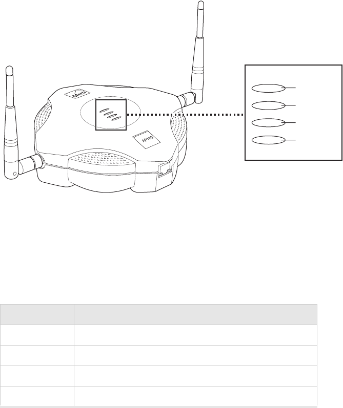
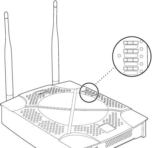
AP200 Status LEDs
Four status LEDs on the face of the AP200 also light, as shown in Figure 23.
.
Figure 23: AP200 Status LEDs
The functions of the status LEDs are described in Table 9.
When the AP200 is first connected to the controller and any time the access point is rebooted there-
after, the AP initializes with and then is programmed by the controller. When the AP is first powered
up, all LEDs are green. Thereafter, the Status LED (see Figure 23) color reflects the various operating
states (Table 9).
AP200
RF2
RF1
STATUS
POWER
11
3

Checking LED Activity
Installing the AP200 33
Table 8: AP200 LED Descriptions
Table 9: AP200-Controller Status Information
LED Function
RF 2 The status LED for Radio 2 is a follows:
off—no radio present
yellow—radio initializing
red—radio failure
solid green—radio OK
blinking green—radio activity
RF 1 The status LED for Radio 1 is a follows:
off—no radio present
yellow—radio initializing
red—radio failure
solid green—radio OK
blinking green—radio activity
Status AP-Controller operational status (see Table 9)
Power green—presence of power
State Interpretation AP200 LED Cycle
Attempting to discover
Controller
In the process of discovering the controller. The
AP is connected but not associated with the con-
troller. If the AP does not associate with the con-
troller after a period of time, verify that the
connection between the AP and the switch or the
switch and the controller is unbroken.
Green/Red/Blue/Red
Connected Normal operation without security. Blue/Blue/Blue/Red
Blue/Blue/Blue/Red, for
2 seconds.
Authenticated Normal operation with security. Blue blinka
Disconnected Access point was once connected to a controller
and configured by the controller, but can no
longer find that controller
Green/Purple/
Green/Purple
Standalone Access point is operating in a standalone mode Purple blink

34 Meru Access Point Installation Guide
Checking LED Activity
Downloading Downloading image or configuration from the
controller
Green/Blue
Green/Blue
Error State Access point is in an error state.
Call Meru technical support
Red (blinking or solid)
a. The AP200 LEDs cycle from bright to dim for each “blink.”
State Interpretation AP200 LED Cycle

Specifications 35
Appendix A
Specifications
This chapter provides specifications for the Meru Access Points and contains the following sections:
zFCC Compliance
zWireless Interface
zEthernet Interface
zPhysical
FCC Compliance
This device complies with part 15 of the FCC Rules. Operation is subject to the following two
conditions: (1) This device may not cause harmful interference, and (2) this device must accept any
interference received, including interference that may cause undesired operation.
Caution!
Changes or modifications to the Meru Access Point that are not expressly approved by
Meru Networks will void your warranty and could void your authority to operate this equipment.

36 Meru Access Point Installation Guide
Wireless Interface
Wireless Interface
Table 10: AP100 Wireless Interface Specifications
Table 11: AP200 Wireless Interface Specifications
Feature Details
Wireless Standards z802.11b
Antennas zTwo external antennas. Omnidirectional and directional antennas for
specific coverage requirements
Wireless Medium Access zWiFi Compliant 802.11 MAC standard
Power Management zPower-save mode for clients in both QoS mode and non-QoS mode
zPower control on transmit power to minimize co-channel
interference of QoS traffic
Frame Size zPeak frame size of > 2250 bytes
zFragmentation and reassembly of 802.11/Ethernet frames
Client Activities
Supported
zActive scanning and passive scanning
zPre-authentication
zPower-save mode supported
Feature Details
Wireless Standards z802.11a, 802.11b, 802.11g
Antennas zTwo external antennas. Omnidirectional and directional antennas for
specific coverage requirements
Wireless Medium Access zWiFi Compliant 802.11 MAC standard
Power Management zPower-save mode for clients in both QoS mode and non-QoS mode
zPower control on transmit power to minimize co-channel
interference of QoS traffic
Frame Size zPeak frame size of > 2250 bytes
zFragmentation and reassembly of 802.11/Ethernet frames
Client Activities
Supported
zActive scanning and passive scanning
zPre-authentication
zPower-save mode supported
Ethernet Interface
Specifications 37
Ethernet Interface
Physical
Physical specifications for Meru Access Points are provided in the access point Data Sheet. Contact
your Meru sales engineer for a copy of the document.
Feature Detail
Wireline Standard zOne 10/100/1000 Mbps Ethernet (IEEE 802.3) interface,
supporting half-duplex and full-duplex modes
zSupports the Power over Ethernet (PoE) IEEE 802.3af
standard
38 Meru Access Point Installation Guide
Physical

Declarations of Conformity and Regulatory Information 39
Appendix B
Declarations of Conformity and Regulatory
Information
B-1
This appendix provides declarations of conformity and regulatory information for Meru Access
Points. This appendix contains the following sections:
zManufacturers Federal Communication Commission Declaration of Conformity Statement
zDepartment of Communications—Canada
zEuropean Community, Switzerland, Norway, Iceland, and Liechtenstein
zDeclaration of Conformity for RF Exposure
zGuidelines for Operating Meru Access Points in Japan
Manufacturers Federal Communication Commission
Declaration of Conformity Statement
Models: AP100, AP100-P, AP200
FCC Certification number:
Manufacturer: Meru Networks, Inc.
1309 S. Mary Avenue
Sunnyvale, CA 94087
USA
This device complies with Part 15 rules. Operation is subject to the following two conditions:
1. This device may not cause harmful interference, and
2. This device must accept any interference received, including interference that may cause
undesired operation.
This equipment has been tested and found to comply with the limits of a Class B digital device,
pursuant to Part 15 of the FCC Rules. These limits are designed to provide reasonable protection
against harmful interference when the equipment is operated in a residential environment. This
equipment generates, uses, and radiates radio frequency energy, and if not installed and used in
accordance with the instructions, may cause harmful interference. However, there is no guarantee that

40 Meru Access Point Installation Guide
Department of Communications—Canada
interference will not occur. If this equipment does cause interference to radio or television reception,
which can be determined by turning the equipment off and on, the user is encouraged to correct the
interference by one of the following measures:
zReorient or relocate the receiving antenna.
zIncrease separation between the equipment and receiver.
zConnect the equipment to an outlet on a circuit different from which the receiver is connected.
zConsult the dealer or an experienced radio/TV technician.
Department of Communications—Canada
Canadian Compliance Statement
This Class B Digital apparatus meets all the requirements of the Canadian Interference-Causing
Equipment Regulations.
Cet appareil numerique de la classe B respecte les exigences du Reglement sur le material broilleur
du Canada.
This device complies with Class B Limits of Industry Canada. Operation is subject to the following
two conditions:
1. This device may not cause harmful interference, and
2. This device must accept any interference received, including interference that may cause
undesired operation.
Meru 11-Mbps, 2.4-GHz AP100 Access Points are certified to the requirements of RSS-210 for 2.4-
GHz spread spectrum devices, and Meru 54-Mbps, 5-GHz AP200 Access Points are certified to the
requirements of RSS-210 for 5-GHz spread spectrum devices.The use of this device in a system
operating either partially or completely outdoors may require the user to obtain a license for the
system according to the Canadian regulations. For further information, contact your local Industry
Canada office.
Caution!
The Part 15 radio device operates on a non-interference basis with other devices operating
at this frequency when using integrated antennas or external antennas. Any changes or
modification to the product not expressly approved by Meru could void the user’s authority
to operate this device.
Caution!
Within the 5.15-5.25 GHz band (5 GHz radio channels 34-48) the U-NII devices are
restricted to indoor operations to reduce any potential for harmful interference to co-
channel Mobile Satellite System (MSS) operations.

European Community, Switzerland, Norway, Iceland, and Liechtenstein
Declarations of Conformity and Regulatory Information 41
European Community, Switzerland, Norway, Iceland, and
Liechtenstein
Declaration of Conformity with Regard to the R&TTE Directive
1999/5/EC
English: This equipment is in compliance with the essential requirements and other relevant
provisions of Directive 1999/5/EC.
Deutsch: Dieses Gerät entspricht den grundlegenden Anforderungen und den weiteren
entsprecheneden Vorgaben der Richtlinie 1999/5/EU.
Dansk: Dette udstyr er i overensstemmelse med de væsentlige krav og andre relevante
bestemmelser i Directiv 1999/5/EF.
Español: Este equipo cumple con los requisitos esenciales asi como con otras disposiciones de la
Directive 1999/5/EC.
Français: Cet appareil est conforme aux exigencies essentialles et aux autres dispositions
pertinantes de la Directive 1999/5/EC.
Íslenska: essi búna ur samr mist lögbo num kröfum og ö rum ákvæ um tilskipunar 1999/5/ESB.
Italiano: Questo apparato é conforme ai requisiti essenziali ed agli altri principi sanciti dalla
Direttiva 1999/5/EC.
Nederlands: Deze apparatuur voldoet aan de belangrijkste eisen en andere voorzieningen van
richtlijn 1999/5/EC.
Norsk: Dette utstyret er i samsvar med de grunnleggende krav og andre relevante bestemmelser i
EU-directiv 1999/5/EC.
Português: Este equipamento satisfaz os requisitos essenciais e outras provisões da Directiva
1999/5/EC.
Suomalainen: Tämä laite täyttää direktiivin 1999/5/EY oleelliset vaatimukset ja on siinä asetettujen
muidenkin ehtojen mukainen.
Svenska: Denna utrustning är i överensstämmelse med de väsentliga kraven och andra relevanta
bestämmelser i Direktiv 1999/5/EC.
B-5
For 11 Mbps, 2.4 GHz access points with 100 mW radios, the following standards were applied:
Radio: EN 300.328-1, EN 300.328-2
EMC: EN 301.489-1, EN 301.89-17
Safety: EN 60950
42 Meru Access Point Installation Guide
Declaration of Conformity for RF Exposure
The following CE mark is affixed to the 11 Mbps, 2.4 GHz access points with 100 mW radios:
For 54 Mbps, 5 GHz access points with 40 mW radios, the following standards were applied:
Radio: EN 301.893
EMC: EN 301.489-1, EN 301.489-17
Safety: EN 60950
The following CE mark is affixed to the 54 Mbps, 5 GHz access points with 40 mW radios:
Declaration of Conformity for RF Exposure
The radio module has been found to be compliant to the requirements set forth in CFR 47 Sections
2.1091, 2.1093, and 15.247 (b) (4) addressing RF Exposure from radio frequency devices as defined
in Evaluating Compliance with FCC Guidelines for Human Exposure to Radio Frequency
Electromagnetic Fields.
The access point (with 5 GHz integrated antenna) must be installed to maintain a minimum 20 cm (7.9
in) co-located separation distance from other FCC approved indoor/outdoor antennas used with the
access point. Any antennas or transmitters not approved by the FCC cannot be co-located with the
access point antennas. The access point’s co-located 2.4 GHz (4 dBi) and 5 GHz (5 dBi) dual-band
standard dipole antennas support a minimum separation distance of 10 cm (3.9 in) and are compliant
with the applicable FCC RF exposure limit when transmitting simultaneously.
Note:
This equipment is intended to be used in all EU and EFTA countries. Outdoor use may be
restricted to certain frequencies and/or may require a license for operation. For more details,
contact Meru Corporate Compliance.
Note:
Combinations of power levels and antennas resulting in a radiated power level above 100
mW equivalent isotropic radiated power (EIRP) are considered as not compliant with the
above mentioned directive and are not allowed for use within the European community and
other countries that have adopted the European R&TTE directive 1999/5/EC or the CEPT
recommendation Rec 70.03 or both.
Note:
Dual antennas used for diversity operation are not considered co-located.
Guidelines for Operating Meru Access Points in Japan
Declarations of Conformity and Regulatory Information 43
Guidelines for Operating Meru Access Points in Japan
This section provides guidelines for avoiding interference when operating Meru Access Points in
Japan. These guidelines are provided in both Japanese and English.
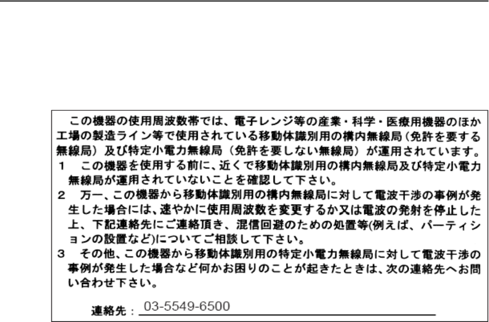
Japanese Translation
English Translation
This equipment operates in the same frequency bandwidth as industrial, scientific, and medical
devices such as microwave ovens and mobile object identification (RF-ID) systems (licensed
premises radio stations and unlicensed specified low-power radio stations) used in factory production
lines.
1. Before using this equipment, make sure that no premises radio stations or specified low-power
radio stations of RF-ID are used in the vicinity.
2. If this equipment causes RF interference to a premises radio station of RF-ID, promptly change
the frequency or stop using the device; contact the number below and ask for recommendations
on avoiding radio interference, such as setting partitions.
3. If this equipment causes RF interference to a specified low-power radio station of RF-ID, contact
the number below.
Contact Number: 03-5549-6500
B-8
44 Meru Access Point Installation Guide
Guidelines for Operating Meru Access Points in Japan
Translated Safety Warnings 45
Appendix C
Translated Safety Warnings
B-1
This appendix provides translations of the safety warnings that appear in this publication. These
translated warnings apply to other documents in which they appear in English. The following safety
warnings appear in this appendix:
zDipole Antenna Installation Warning
zExplosive Device Proximity Warning
zInstallation Warning
zCircuit Breaker (15A) Warning
46 Meru Access Point Installation Guide
Dipole Antenna Installation Warning
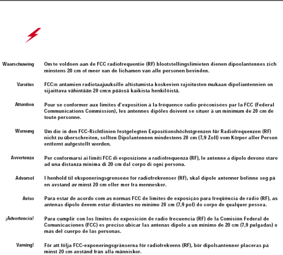
Dipole Antenna Installation Warning
Warning!
In order to comply with FCC radio frequency (RF) exposure limits, dipole
antennas should be located at a minimum of 7.9 inches (20 cm) or more from the body of
all persons.
Explosive Device Proximity Warning
Translated Safety Warnings 47
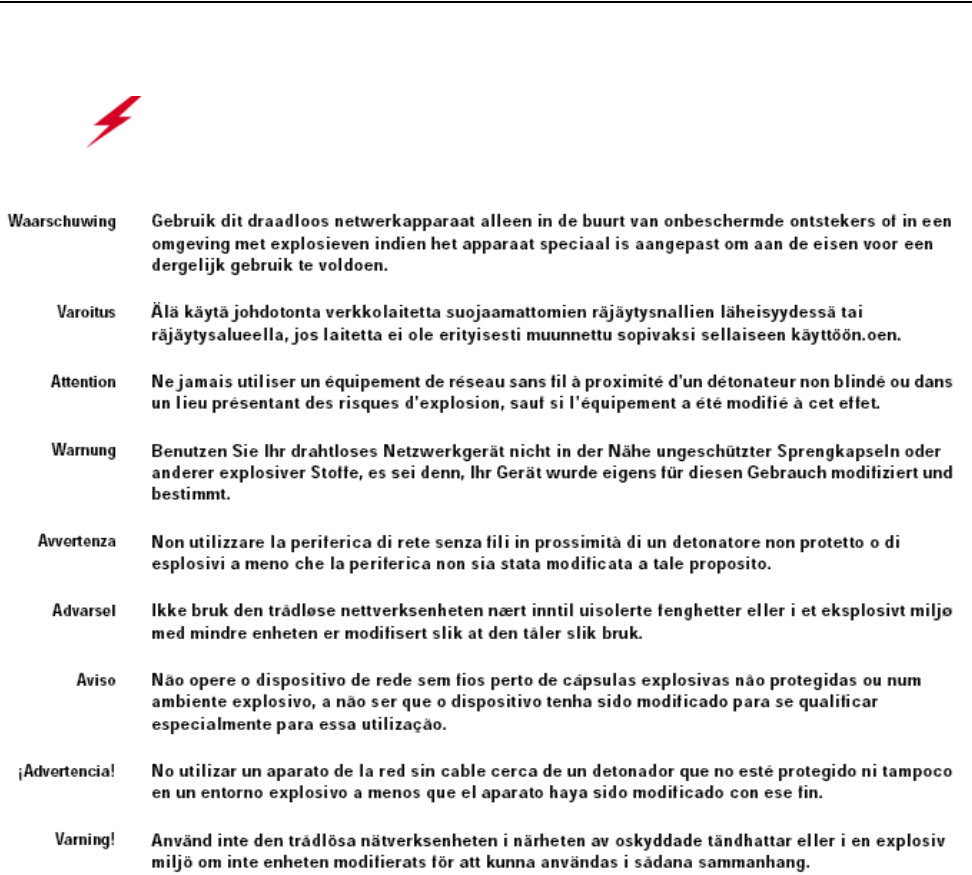
Explosive Device Proximity Warning
Warning!
Do not operate your wireless network device near unshielded blasting caps or
in an explosive environment unless the device has been modified to be especially qualified
for such use.
48 Meru Access Point Installation Guide
Installation Warning
Installation Warning
Warning!
Read the installation instructions before you connect the system to its power
source.
Circuit Breaker (15A) Warning
Translated Safety Warnings 49
Circuit Breaker (15A) Warning
Warning!
This product relies on the building’s installation for short-circuit (overcurrent)
protection. Ensure that a fuse or circuit breaker no larger than 120 VAC, 15A U.S. (240
VAC, 10A international) is used on the phase conductors (all current-carrying conductors).
50 Meru Access Point Installation Guide
Circuit Breaker (15A) Warning

Channels 51
Appendix D
Channels
B-1
This appendix provides the access point radio channels supported by the world’s regulatory domains.
This appendix contains the following section:
zChannels
Channels
IEEE 802.11a
The channel identifiers, channel center frequencies, and regulatory domains of each IEEE 802.11a
20-MHz-wide channel are listed in Table 12.
Note:
All channel sets are restricted to indoor usage except the Americas, which allow for indoor
and outdoor use on channels 52 through 64 in the United States.
Table 12: IEEE 802.11a Channels
Channel
Number
Frequency in
MHz
Regulatory Domains
Americas Japan Singapore Taiwan
34 5170 - X - -
36 5180 X - X -
38 5190 - X - -
40 5200 X - X -
42 5210 - X - -

52 Meru Access Point Installation Guide
Channels
IEEE 802.11b/g
The channel identifiers, channel center frequencies, and regulatory domains of each IEEE 802.11b/g
22-MHz-wide channel are listed in Table 13.
44 5220 X - X -
46 5230 - X - -
48 5240 X - X -
52 5260 X - - X
56 5280 X - - X
60 5300 X - - X
64 5320 X - - X
149 5745 - - - -
153 5765 - - - -
157 5785 - - - -
161 5805 - - - -
Table 12: IEEE 802.11a Channels (Continued)
Channel
Number
Frequency in
MHz
Regulatory Domains
Americas Japan Singapore Taiwan
Note:
Mexico is included in the Americas regulatory domain; however, channels 1 through 8 are
for indoor use only while channels 9 through 11 can be used indoors and outdoors. Users
are responsible for ensuring that the channel set configuration complies with the regulatory
standards of Mexico.
Table 13: IEEE 802.11b/g Channels
Channel
Number
Frequency in
MHz
Regulatory Domains
Americas EMEA Israel China Japan
1 2412 X X - X X
2 2417 X X - X X
3 2422 X X X X X

Channels
Channels 53
4 2427 X X X X X
5 2432 X X X X X
6 2437 X X X X X
7 2442 X X X X X
8 2447 X X X X X
9 2452 X X X X X
10 2457 X X - X X
11 2462 X X - X X
12 2467 - X - - X
13 2472 - X - - X
14 2484 - - - - X
Table 13: IEEE 802.11b/g Channels (Continued)
Channel
Number
Frequency in
MHz
Regulatory Domains
Americas EMEA Israel China Japan
54 Meru Access Point Installation Guide
Channels
55
MERU NETWORKS, INC.
Limited Product Warranty
This Limited Product Warranty applies to the original end-user customer of the Meru product which you purchased for your
own use, and not for resale (“Product”), from Meru Networks, Inc. (“Meru”) or its authorized reseller (“Reseller”).
Limited Warranties
—One-year limited hardware warranty: Meru warrants to you that Meru hardware (other than Third Party Products
as described below) will be free from defects in materials and workmanship for a one-year period after the date of
delivery of the applicable product to you from Meru or its Reseller (the “Hardware Warranty Period”). If Meru
receives written notice from you of such defects during the Hardware Warranty Period, Meru will, at its option,
either repair or replace Meru hardware that Meru determines to be defective. Replacement products may be reman-
ufactured units, and will be warranted for the remainder of the original Hardware Warranty Period, or if greater, for
thirty days from delivery of such replacement. Should Meru be unable to repair or replace the Meru hardware, Meru
(or its Reseller, as applicable) will refund to you the purchase price of the Product.
—90-Day Limited Software Warranty: Meru warrants to you that, for a 90-day period after the date of delivery of the
applicable product to you from Meru or its Reseller (the “Software Warranty Period”), when properly installed and
used, (a) the media on which the Meru software is provided will be free from defects in materials or workmanship;
and (b) the Meru software will substantially conform to the functional specifications in the applicable documenta-
tion. If Meru receives written notice from you of a breach of this warranty during the Software Warranty Period
and is able to reproduce the defect, Meru will, at its option, either repair or replace the defective Meru software.
Should Meru be unable to repair or replace the Meru software, Meru (or its Reseller, as applicable) will refund to
you the purchase price of the Product.
Exclusions
The warranty on the Product shall not apply to defects resulting from the following:
—Alteration or modification of the Product in any way, including without limitation configuration with software or
components other than those supplied by Meru or integration with parts other than those supplied by Meru.
—Abuse, damage or otherwise being subjected to problems caused by negligence or misapplication (including
without limitation improper or inadequate maintenance or calibration), relocation of the products (including
without limitation damage caused by use of other than Meru shipping containers), or use of the products other than
as specified in the applicable Meru product documentation (including without limitation incompatible operating
environments and systems), or improper site preparation or maintenance.
—Damage as a result of accidents, extreme power surge, extreme electromagnetic field, acts of nature or other causes
beyond the control of Meru.
—Use of the Product with software, interfacing, parts or supplies not supplied by Meru.
The warranty on the Product does not apply if the Product is sold, or in the case of software, licensed, for free for
evaluation or demonstration purposes.
Meru expressly disclaims any warranty or obligation to support the Product for all operating environments – for example,
as illustration and not limitation, Meru does not warrant or ensure interoperability of the Product with future
telecommunication systems or other future software or hardware.
You understand and acknowledge that the Products may generate, use or radiate radio frequency energy and may interfere
with radio communications and/or radio and television receptions if is not used and/or installed in accordance with the
documentation for such products. WHILE MERU USES COMMERCIALLY REASONABLE EFFORTS TO ENSURE
COMPLIANCE OF THE PRODUCTS WITH APPLICABLE UNITED STATES FEDERAL COMMUNICATIONS
COMMISSION AND PROTECT AGAINST HARMFUL INTERFERENCES, YOU ACKNOWLEDGE AND AGREE
56 Meru Access Point Installation Guide
THAT INTERFERENCES WITH RADIO COMMUNICATIONS AND/OR RADIO AND TELEVISION RECEPTIONS
MAY OCCUR AND THAT MERU WILL NOT BE LIABLE FOR ANY DAMAGES OR INCONVENIENCE BASED
ON SUCH INTERFERENCES.
Third Party Products - The above Limited Warranties are exclusive of products manufactured by third parties (“Third
Party Products”). If such third party manufacturer provides a separate warranty with respect to the Third Party Product,
Meru will include such warranty in the packaging of the Meru Product.
Return procedures
To obtain warranty service you must: (a) obtain a return materials authorization number (“RMA#”) from Meru by
contacting support@merunetworks.com, and (b) deliver the Product, in accordance with the instructions provided by Meru,
along with proof of purchase in the form of a copy of the bill of sale including the Product’s serial number, contact
information, RMA# and detailed description of the defect, in either its original package or packaging providing the Product
with a degree of protection equivalent to that of the original packaging, to Meru at the address below. You agree to obtain
adequate insurance to cover loss or damage to the Product during shipment.
If you obtain an RMA# and return the defective Product as described above, Meru will pay the cost of returning the Product
to Meru. Otherwise, you agree to bear such cost, and prior to receipt by Meru, you assume risk of any loss or damage to
the Product. Meru is responsible for the cost of return shipment to you if the Meru Product is defective.
Returned products which are found by Meru to be not defective, returned out-of-warranty or otherwise ineligible for
warranty service will be repaired or replaced at Meru’s standard charges and shipped back to you at your expense.
At Meru’s sole option, Meru may perform repair service on the Product at your facility, and you agree to provide Meru with
all reasonable access to such facility and the Product, as required by Meru. On-site repair service may be available and is
governed by the specific terms of your purchase.
All replaced parts, whether under warranty or not, are the property of Meru.
Warranty limitations
THE WARRANTIES SET FORTH ABOVE ARE EXCLUSIVE AND NO OTHER WARRANTY, WHETHER
WRITTEN OR ORAL, IS EXPRESSED OR IMPLIED BY MERU, TO THE MAXIMUM EXTENT PERMITTED BY
LAW. THERE ARE NO OTHER WARRANTIES RESPECTING THE PRODUCT AND DOCUMENTATION AND
SERVICES PROVIDED UNDER THIS AGREEMENT, INCLUDING WITHOUT LIMITATION ANY WARRANTY OF
DESIGN, MERCHANTABILITY, FITNESS FOR A PARTICULAR PURPOSE (EVEN IF MERU HAS BEEN
INFORMED OF SUCH PURPOSE), TITLE OR AGAINST INFRINGEMENT OF THIRD PARTY RIGHTS. IF ANY
IMPLIED WARRANTY CANNOT BE DISCLAIMED UNDER APPLICABLE LAW, THEN SUCH IMPLIED
WARRANTY SHALL BE LIMITED IN DURATION TO THE HARDWARE AND SOFTWARE WARRANTY
PERIODS DESCRIBED ABOVE.
NO AGENT OF MERU IS AUTHORIZED TO ALTER OR EXCEED THE WARRANTY OBLIGATIONS OF MERU.
MERU SPECIFICALLY DOES NOT WARRANT THAT THE MERU SOFTWARE WILL BE ERROR FREE OR
OPERATE WITHOUT INTERRUPTION.
57
THE REMEDIES IN THIS LIMITED PRODUCT WARRANTY ARE YOUR SOLE AND EXCLUSIVE REMEDIES,
AND MERU’S SOLE AND EXCLUSIVE LIABILITY, FOR BREACH OF THE HARDWARE OR SOFTWARE
WARRANTY SET FORTH ABOVE.
Limitations of Liability
You acknowledge and agree that the consideration which you paid to Meru does not include any consideration by Meru of
the risk of consequential, indirect or incidental damages which may arise in connection with your use of, or inability to use,
the Product. THUS, MERU AND ITS RESELLER WILL NOT BE LIABLE FOR ANY INDIRECT, INCIDENTAL,
SPECIAL, PUNITIVE OR CONSEQUENTIAL DAMAGES, INCLUDING WITHOUT LIMITATION LOST PROFITS,
LOST BUSINESS, LOST DATA, LOSS OF USE, OR COST OF COVER INCURRED BY YOU ARISING OUT OF OR
RELATED TO YOUR PURCHASE OR USE OF, OR INABILITY TO USE, THIS PRODUCT OR THE SERVICES,
UNDER ANY THEORY OF LIABILITY, WHETHER IN AN ACTION IN CONTRACT, STRICT LIABILITY, TORT
(INCLUDING NEGLIGENCE) OR OTHER LEGAL OR EQUITABLE THEORY, EVEN IF MERU OR ITS RESELLER
KNEW OR SHOULD HAVE KNOWN OF THE POSSIBILITY OF SUCH DAMAGES. IN ANY EVENT, THE
CUMULATIVE LIABILITY OF MERU OR ITS RESELLER FOR ALL CLAIMS WHATSOEVER RELATED TO THE
PRODUCT OR THE SERVICE WILL NOT EXCEED THE PRICE YOU PAID FOR THE PRODUCT OR SERVICES
GIVING RISE TO SUCH CLAIMS.
THE LIMITATIONS SET FORTH HEREIN ARE INTENDED TO LIMIT THE LIABILITY OF MERU AND ITS
RESELLERS AND SHALL APPLY NOTWITHSTANDING ANY FAILURE OF ESSENTIAL PURPOSE OF ANY
LIMITED REMEDY.
The jurisdiction applicable to you may not allow the limitations of liability or damages set forth above, in which case such
limitation shall only apply to you to the extent permitted in such jurisdiction.
Additional Information
This Limited Product Warranty shall be governed by and construed in accordance with the laws of the State of California,
U.S.A., exclusive of its conflict of laws principles. The U.N. Convention on Contracts for the International Sale of Goods
shall not apply.
This Limited Product Warranty is the entire and exclusive agreement between you and Meru with respect to its subject
matter, and any modification or waiver of any provision of this statement is not effective unless expressly set forth in
writing by an authorized representative of Meru.
All inquiries or claims made under this Limited Product Warranty must be sent to Meru at the following address:
Meru Networks Inc.,
1309 South Mary Avenue, Sunnyvale, CA 94087, USA
Tel: 408-215-5300
Fax: 408-215-5301
Email: support@merunetworks.com
58 Meru Access Point Installation Guide

59