Meru Networks AP300 MULTI RADIO 802.11a/b/g/n WIRELESS LAN ACCESS POINT User Manual AP300
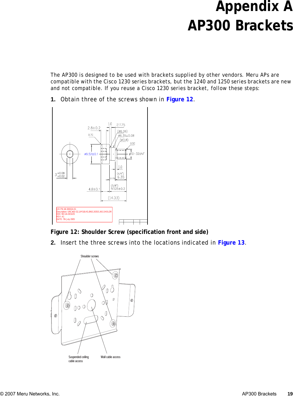
Meru Networks Inc. MULTI RADIO 802.11a/b/g/n WIRELESS LAN ACCESS POINT AP300
UserManual.wiki
>
Meru Networks
>
AP300 User Manual
>
Users Manual
Contents
1.
USERS MANUAL
2.
Users Manual
3.
Users Manual Leaflet 1
4.
Users Manual Leaflet 2
5.
Users Manual Leaflet 3
6.
Users Manual Leaflet 4
7.
Users Manual Leaflet 5
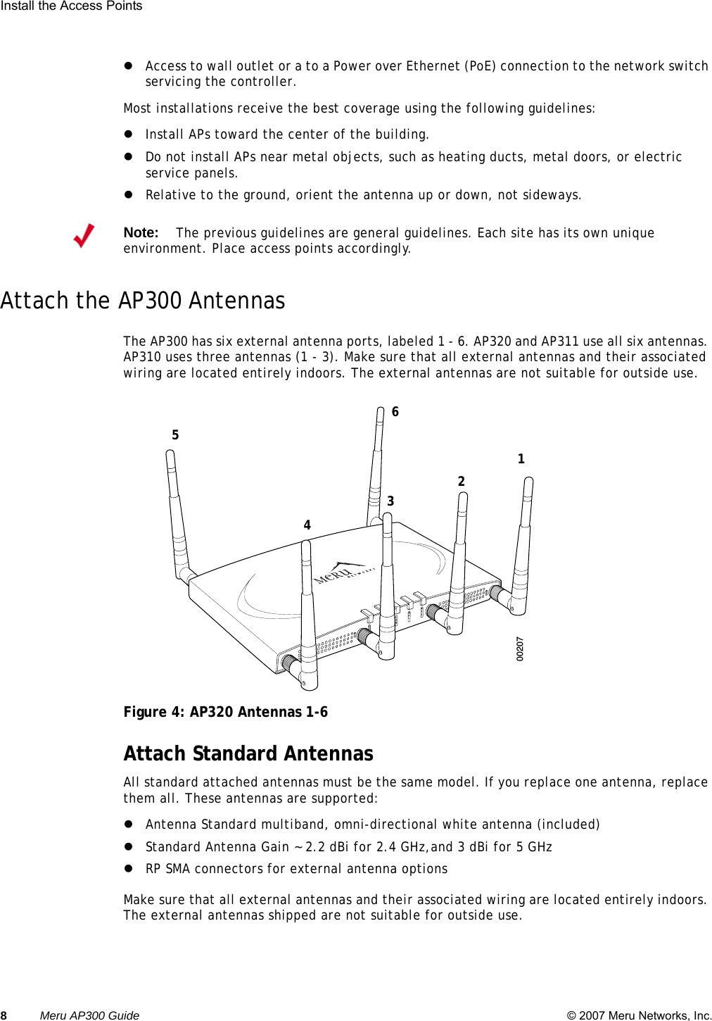
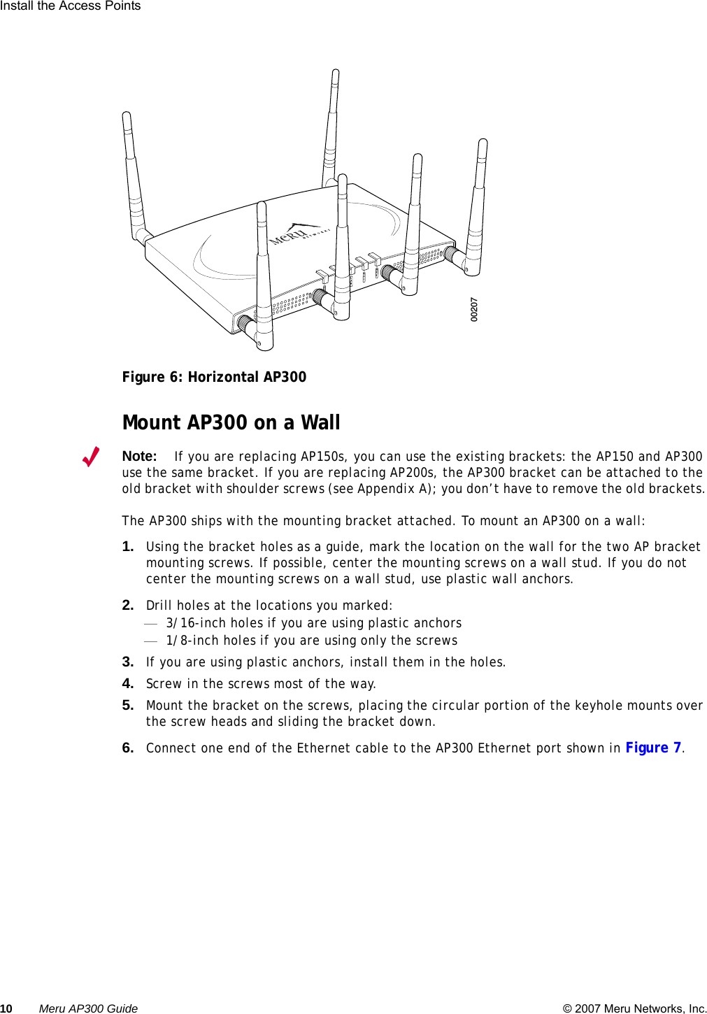
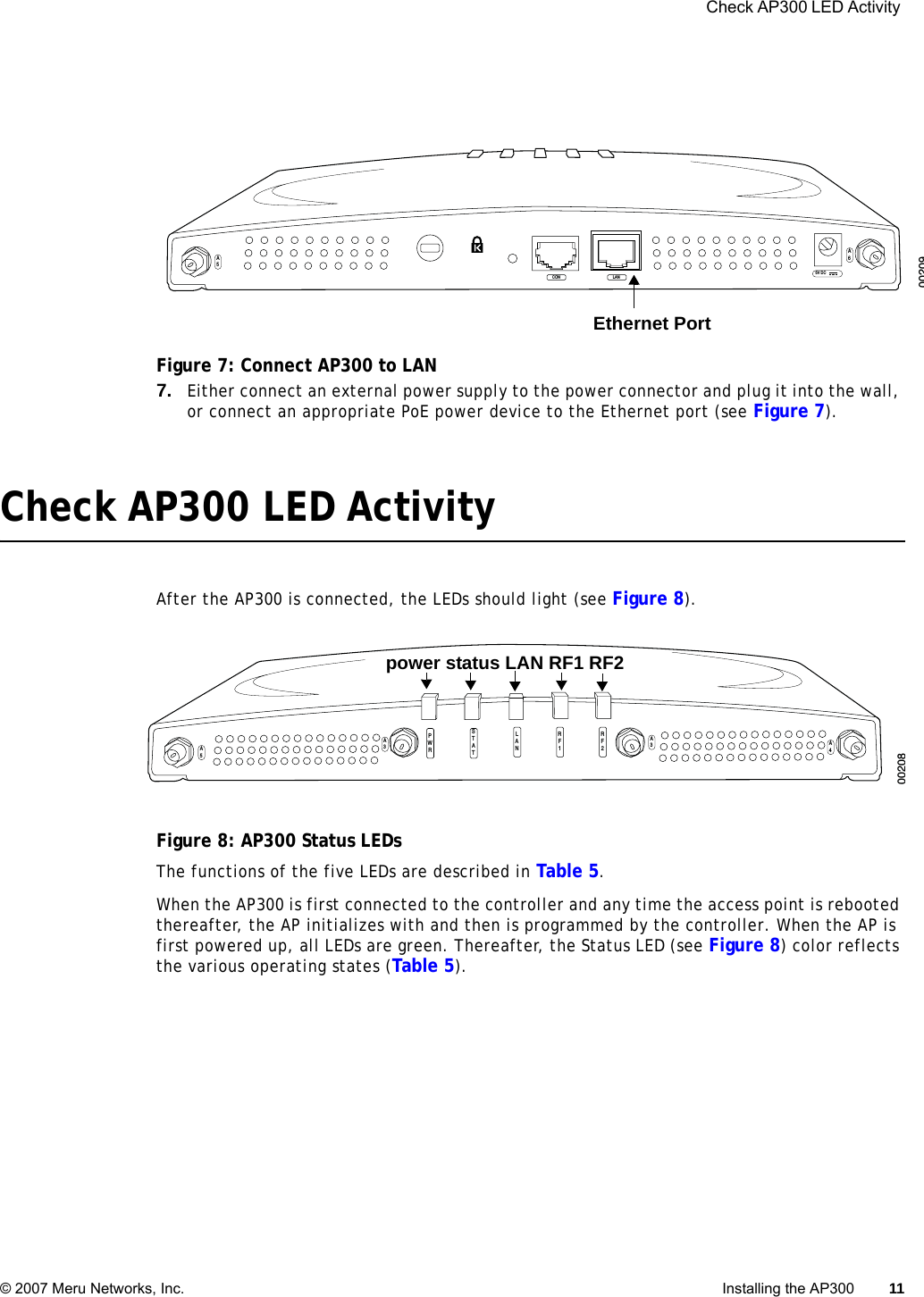
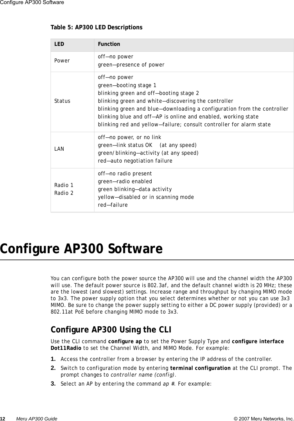
Users Manual
Navigation menu
Upload a User Manual
Namespaces
Wiki Guide
HTML
PDF
Info
Views
User Manual
Discussion / Help
Navigation
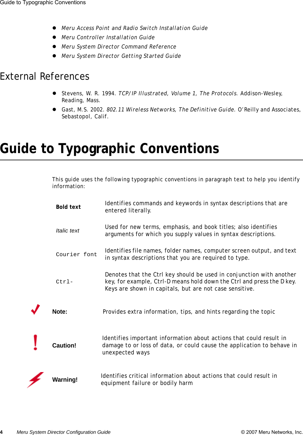
![Syntax Notation © 2007 Meru Networks, Inc. About This Guide 5 Syntax NotationIn example command syntax descriptions and examples, the following text elements and punc-tuation are used to denote user input and computer output for the command. In general, Courier font is used for command input and output at the command line; bold indicates required text and italics indicates values that are to be replaced. The following figure shows a sample of syntax notation.bold Required command, keywords, and punctuation.italic Arguments or file names where you substitute a value.no The optional no form of the command disables the feature or function. [ ] Optional elements are enclosed by square brackets.{ } Braces indicates that one of the enclosed elements must be used.|Choices among elements are separated by vertical bars.[{}] A required choice within an optional element.…The preceding argument can be repeated. [no] action target {keyword|keyword}Command or action. In some cases, action takes you to another command mode.One or more repeated values[argument ...]Choose between the enclosed elements The optional no form disables the command; without the no, enables or re-enables.Keyword or command within a submode.Note:Many commands have a default setting or value, listed in the Default section of the command page.](https://usermanual.wiki/Meru-Networks/AP300.Users-Manual/User-Guide-1344516-Page-7.png)