Meru Networks AP300 MULTIRADIO 802.11A/B/G/N WIRELESS LAN ACCESS POINT User Manual AP300
Meru Networks Inc. MULTIRADIO 802.11A/B/G/N WIRELESS LAN ACCESS POINT AP300
Contents
USERS MANUAL

Meru AP300
Installation Guide
September 14, 2007
Copyright © Meru Networks, Inc., 2003–2007. All rights reserved.
Other names and brands may be claimed as the property of others.
Contents 1
Controlled Use Only—Beta Draft
Contents
About This Guide . . . . . . . . . . . . . . . . . . . . . . . 3
Audience . . . . . . . . . . . . . . . . . . . . . . . . . 3
Other Sources of Information . . . . . . . . . . . . . . . . . . 3
Meru Publications . . . . . . . . . . . . . . . . . . . . . 3
External References . . . . . . . . . . . . . . . . . . . . 4
Guide to Typographic Conventions . . . . . . . . . . . . . . . . 4
Syntax Notation. . . . . . . . . . . . . . . . . . . . . . . 5
Contacting Meru . . . . . . . . . . . . . . . . . . . . . . 6
Customer Services and Support . . . . . . . . . . . . . . . . 6
AP300 Series Introduction . . . . . . . . . . . . . . . . . . 1
Hardware Specification . . . . . . . . . . . . . . . . . . . 2
AP300 Product Overview . . . . . . . . . . . . . . . . . . 2
Installing the AP300 . . . . . . . . . . . . . . . . . . . . . 3
Safety Precautions. . . . . . . . . . . . . . . . . . . . . . 3
Unpack the AP300 . . . . . . . . . . . . . . . . . . . . . . 4
Determine Power Requirements . . . . . . . . . . . . . . . . . 5
Installation Requirements . . . . . . . . . . . . . . . . . . . 5
Additional Equipment . . . . . . . . . . . . . . . . . . . 7
Install the Access Points . . . . . . . . . . . . . . . . . . . . 7
Select a Location . . . . . . . . . . . . . . . . . . . . . 7
Attach the AP300 Antennas . . . . . . . . . . . . . . . . . 8
Attach Standard Antennas . . . . . . . . . . . . . . . . . 8
Attach Remote Antennas . . . . . . . . . . . . . . . . . 9
Mount the Access Point . . . . . . . . . . . . . . . . . . . 9
Mount AP300 Horizontally . . . . . . . . . . . . . . . . . 9
Mount AP300 on a Wall . . . . . . . . . . . . . . . . . . 10
Check AP300 LED Activity . . . . . . . . . . . . . . . . . . . 11
Configure AP300 Software . . . . . . . . . . . . . . . . . . . 12
Configure AP300 Using the CLI . . . . . . . . . . . . . . . 12
Configure AP300 Using the GUI . . . . . . . . . . . . . . . 14
Troubleshooting. . . . . . . . . . . . . . . . . . . . . . . 17
AP300 Brackets. . . . . . . . . . . . . . . . . . . . . . . 19
Specifications . . . . . . . . . . . . . . . . . . . . . . . 21
Wireless Interface for All APs . . . . . . . . . . . . . . . . . . 21
Ethernet Interface for All Meru APs . . . . . . . . . . . . . . . . 22
2Meru System Director Getting Started Guide
Controlled Use Only—Beta Draft
Physical Description for All Meru APs . . . . . . . . . . . . . . . 22
Regulatory Information . . . . . . . . . . . . . . . . . . .23
USA . . . . . . . . . . . . . . . . . . . . . . . . . . 23
Underwriters Laboratories . . . . . . . . . . . . . . . . . 23
Notices. . . . . . . . . . . . . . . . . . . . . . . 23
FCC Radiation Exposure Statement . . . . . . . . . . . . . . 24
Radio Frequency Interference Requirements . . . . . . . . . . . 24
Interference Statement . . . . . . . . . . . . . . . . . 24
Channels . . . . . . . . . . . . . . . . . . . . . . . . . .27
IEEE 802.11a . . . . . . . . . . . . . . . . . . . . . . 27
IEEE 802.11b/g . . . . . . . . . . . . . . . . . . . . . 28
IEEE 802.11n . . . . . . . . . . . . . . . . . . . . . . 30

© 2007 Meru Networks, Inc. About This Guide 3
About This Guide
zThis guide describes the various options for configuring the Meru AP300 and the wireless
LAN. The architecture and fundamental operations of system are described.
Audience
This guide is intended for network administrators configuring and maintaining the Meru AP300.
Familiarity with the following concepts is helpful when configuring the Meru Wireless LAN
System:
zNetwork administration, including:
—Internet Protocol (IP) addressing and routing
—Dynamic Host Configuration Protocol (DHCP)
—Configuring Layer 2 and Layer 3 switches (if required by your switch)
zIEEE 802.11n (Wi-Fi) concepts, including:
—ESSIDs
—WEP
zNetwork Security (optional)
—WPA
—802.1X
—RADIUS
—X.509 certificates
Other Sources of Information
Additional information is available in the following Meru publications, Web site, and external
references.
Meru Publications
zMeru AP300 Install Guide
zMeru System Director Release Notes

4Meru System Director Configuration Guide © 2007 Meru Networks, Inc.
Guide to Typographic Conventions
zMeru Access Point and Radio Switch Installation Guide
zMeru Controller Installation Guide
zMeru System Director Command Reference
zMeru System Director Getting Started Guide
External References
zStevens, W. R. 1994. TCP/IP Illustrated, Volume 1, The Protocols. Addison-Wesley,
Reading, Mass.
zGast, M.S. 2002. 802.11 Wireless Networks, The Definitive Guide. O’Reilly and Associates,
Sebastopol, Calif.
Guide to Typographic Conventions
This guide uses the following typographic conventions in paragraph text to help you identify
information:
Bold text Identifies commands and keywords in syntax descriptions that are
entered literally.
Italic text Used for new terms, emphasis, and book titles; also identifies
arguments for which you supply values in syntax descriptions.
Courier font Identifies file names, folder names, computer screen output, and text
in syntax descriptions that you are required to type.
Ctrl- Denotes that the Ctrl key should be used in conjunction with another
key, for example, Ctrl-D means hold down the Ctrl and press the D key.
Keys are shown in capitals, but are not case sensitive.
Note:
Provides extra information, tips, and hints regarding the topic
Caution!
Identifies important information about actions that could result in
damage to or loss of data, or could cause the application to behave in
unexpected ways
Warning!
Identifies critical information about actions that could result in
equipment failure or bodily harm

Syntax Notation
© 2007 Meru Networks, Inc. About This Guide 5
Syntax Notation
In example command syntax descriptions and examples, the following text elements and punc-
tuation are used to denote user input and computer output for the command. In general,
Courier font is used for command input and output at the command line; bold indicates
required text and italics indicates values that are to be replaced.
The following figure shows a sample of syntax notation.
bold Required command, keywords, and punctuation.
italic Arguments or file names where you substitute a value.
no The optional no form of the command disables the feature or function.
[ ] Optional elements are enclosed by square brackets.
{ } Braces indicates that one of the enclosed elements must be used.
|Choices among elements are separated by vertical bars.
[{}] A required choice within an optional element.
…The preceding argument can be repeated.
[no] action target {keyword|keyword}
Command or action. In some cases, action takes you to another command mode.
One or more repeated values
[argument ...]
Choose between the enclosed elements
The optional no form disables the command; without the no, enables or re-enables.
Keyword or command within a submode.
Note:
Many commands have a default setting or value, listed in the Default section of
the command page.

6Meru System Director Configuration Guide © 2007 Meru Networks, Inc.
Contacting Meru
Contacting Meru
You can visit Meru Networks on the Internet at this URL:
http://www.merunetworks.com
Click Support to view Meru Customer Services and Support information.
Customer Services and Support
For assistance, contact Meru Customer Services and Support 24 hours a day at +1-888-637-8952
(+1-888-Meru-WLA(N)) or +1-408-215-5305. Email can be sent to support@merunetworks.com.
Meru Customer Services and Support provide end users and channel partners with the
following:
zTelephone technical support
zSoftware update support
zSpare parts and repair service
© 2007 Meru Networks, Inc. AP300 Series Introduction 1
Chapter 1
AP300 Series Introduction
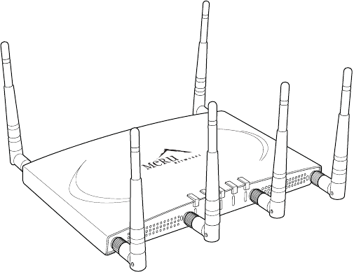
The Meru AP300 Access Point delivers high performance, full-speed, draft 2.0 compatible
802.11n connectivity while simultaneously supporting legacy 802.11a/b/g devices. The Meru
Networks family of AP300 Access Points is supported by System Director Release 3.4.SR3 and
later.
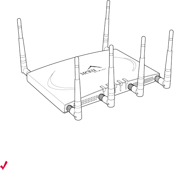
Figure 1: AP300
Key product features include:
z802.11n support with channel bonding in both 2.4GHz and 5GHz frequency bands. Channel
bonding combines two 20Mhz channels into a single-wide 40Mhz channel for increased
theoretical throughput.
zDual-band external antenna options optimized for MIMO mode
zPlug and Play deployment using centralized Meru Controller platforms
zMulti-layered security including standard WPA2, 802.11i security such as automatic traffic
inspection
This access point is available in three different configurations:
zAP320: Two 802.11n radios with 3x3 MIMO mode streams
zAP310: Single 802.11n radio with 3x3 MIMO mode stream
zAP311: Single 802.11n radio with 3x3 MIMO mode stream and single 802.11a/b/g radio
(upgradeable)
A
2
A
2
A
L
A
N
R
F
1
R
F
2
2
00207
2Meru Access Point and Radio Switch Installation Guide © 2007 Meru Networks, Inc.
Each of these Access points may be powered by a standard 802.3af for 2x2 MIMO Mode. For 3x3
full channel mode, use either a power supply or a a 802.3at PoE device.
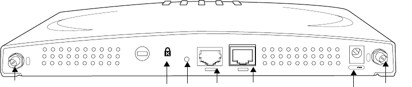
Hardware Specification
The AP300 hardware platform features:
z10/100/1000 Ethernet port, copper
z1 serial/console port (reserved)
zDC power input (5 Volts)
z6 RPSMA external antenna connectors
Figure 2: AP300
AP300 Product Overview
The Meru AP300 Series, supported by System Director release 3.4.SR3 and later, includes the
following features:
zAir Traffic Control technology for 802.11n devices and legacy a/b/g devices
z3x3 MIMO (Multiple Input, Multiple Output) technology with three dedicated, configurable
input/output streams that deliver data rates up to 300 Mbps
zSoftware upgradeable radios for maximum investment protection
zMeru channel span architecture which requires no channel planning or configuration
zSix standard multiband, omni-directional antennas for AP320 and AP311. Three standard
multiband, omni-directional antennas for AP310.
zPowered by 5 volt DC input, 802.11af compliant PoE device, or 802.11at compliant PoE
device.
A
5
A
6
5V DC
CON LAN
00209
Ethernet
Port
serial
port power antenna
(5 of 6)
antenna
(6 of 6) lock reset

Safety Precautions
© 2007 Meru Networks, Inc. Installing the AP300 3
Chapter 2
Installing the AP300
This chapter describes how to physically install the Meru AP300. It contains the following
sections:
zSafety Precautions
zUnpack the AP300
zDetermine Power Requirements
zInstallation Requirements
zInstall the Access Points
zConfigure AP300 Software
zCheck AP300 LED Activity
zConfigure AP300 Software
zTroubleshooting
Safety Precautions
IMPORTANT—Read and follow the regulatory instructions in Appendix C before installing and
operating this product.
This product is intended to be supplied by a UL Listed power supply, marked Class 2 or LPS,
and rated minimum 5 Vdc, 3A.
Caution!
The AP300 is not certified for plenum installations, and should not be installed in
the plenum space.
Document Number: 3.5.1 Rev 1

4Meru AP300 Guide © 2007 Meru Networks, Inc.
Unpack the AP300
Unpack the AP300
The Meru AP300 series consists of the 3 models shown in Table 1. Depending which model you
are installing, you will have either six or three antennas. Drawings in this chapter show six
antennas.
Table 1: Meru AP300 Radios and Antennas
Confirm that the AP300 shipping package contains these items:
zAP300 with attached mounting bracket
zSix (AP320, AP311) or three (AP310) antennas
zPower supply
Model 1st Radio 2nd Radio
AP320 a/b/g/n with 3 dual band
omni-directional antennas a/b/g/n with 3 dual band
omni-directional antennas
AP311 a/b/g/n with 3 dual band
omni-directional antennas
a/b/g with 3 dual band omni-
directional antennas (upgrade-
able)
AP310 a/b/g/n with 3 dual band
omni-directional antennas NA

Determine Power Requirements
© 2007 Meru Networks, Inc. Installing the AP300 5
Determine Power Requirements
Your power requirements will vary, depending on which AP300 radios are deployed and what
mode is used. See Table 2.
Table 2: AP300 Power Options
Installation Requirements
The AP300 standard mounting bracket can be removed. The AP300 is also designed to be used
with brackets supplied by other vendors; if you use a bracket other than an AP150 bracket
(which is identical), you need to obtain three shoulder screws (see Appendix A). Meru APs can
be mounted on Cisco 1230 series brackets, but the Cisco 1240 and 1250 series brackets are new
and not compatible with the Meru bracket.
The AP300 has a security cable slot so you can lock the AP300 with a standard security cable,
such as those used to secure laptop computers. See Figure 3.
AP300 Configuration Power Options
1 radio – b/g mode Either a power supply (included) or PoE
802.3af
1 radio – n-mode Either a power supply (included) or PoE
802.3af
2 radios – 1 b/g-mode, 1 n mode
For 2x2 MIMO mode, use either a power
supply (included) or PoE 802.3af.
For 3x3 MIMO mode, use either a power
supply (included) or a PoE 802.3at.
2 radios – both in n mode
For 2x2 MIMO mode, use either a power
supply (included) or PoE 802.3af.
For 3x3 MIMO mode, use either a power
supply (included) or a PoE 802.3at.
6Meru AP300 Guide © 2007 Meru Networks, Inc.
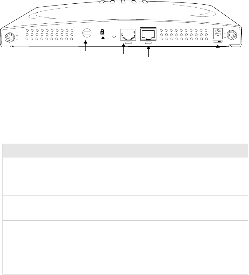
Installation Requirements
Figure 3: AP300 Bottom View
An array of holes on the mounting bracket allows the AP300 to be mounted on the wall and
over junction boxes or molly bolts. There are holes for passing the PoE Ethernet or external
power supply cable through the bracket if the bracket is mounted on a junction box.
To complete this installation, you need the items listed in Table 3.
Table 3: AP300 Installation Items
Installation Type Consumable Items Required
Horizontal mounting None
Vertical mounting over a wall stud
zTwo #6 x 2" wood screws for a wood stud; or
zTwo #6 x 1½" metal screws for a metal stud
zMounting bracket
Vertical mounting on sheetrock
zTwo #6 x 1" screws
zTwo #4-6 x 7/8" ribbed plastic wall anchors
zMounting bracket
Horizontal mounting below a hang-
ing ceiling
zTwo caddy fasteners
zTwo plastic spacers
zTwo keps nuts (with attached lock washer)
zMounting bracket
Using existing Cisco 1230 series
brackets
zspecial screws - see Appendix A
A
5
A
6
5V DC
CON LAN
00209
Ethernet
port
serial
port
power
lock reset

Install the Access Points
© 2007 Meru Networks, Inc. Installing the AP300 7
Table 4: AP300 Installation Tools
Additional Equipment
A power source is provided with the AP300. If you want to use a PoE, you need to provide one
of the following:
z802.3af compliant PoE device (for 2x2 mode)
z802.3at compliant PoE device (needed for 3x3 mode)
Install the Access Points
Select a Location
The AP300 is only intended for installation in Environment A as defined in IEEE 802.3af. All
interconnected equipment must be contained within the same building, including the inter-
connected equipment's associated LAN connection. In addition, the AP300 should be mounted
in a location that meets the following conditions:
zRelatively unobstructed access to the stations the AP serves. Select a location with minimal
physical obstructions between the AP and the wireless stations. In an office with cubicles,
mounting the APs below a hanging ceiling (plenum testing is not complete at this time) or
the wall near the ceiling provides the least obstructed communications path. For an
external power supply connection, ensure the power source is near to where the AP300 will
be mounted.
Installation Type Tools Required
Horizontal mounting None
Vertical mounting over a wall stud
zDrill
z1/8"drill bit
zScrewdriver
z1/8"Allen wrench
Vertical mounting on sheetrock
zDrill
z3/16" drill bit
zScrewdriver
z1/8"Allen wrench
Horizontal mounting below a hang-
ing ceiling
zScrewdriver
zWrench or pliers
z1/8"Allen wrench
Using existing Cisco 1230 series
brackets
zScrewdriver
8Meru AP300 Guide © 2007 Meru Networks, Inc.
Install the Access Points
zAccess to wall outlet or a to a Power over Ethernet (PoE) connection to the network switch
servicing the controller.
Most installations receive the best coverage using the following guidelines:
zInstall APs toward the center of the building.
zDo not install APs near metal objects, such as heating ducts, metal doors, or electric
service panels.
zRelative to the ground, orient the antenna up or down, not sideways.
Attach the AP300 Antennas
The AP300 has six external antenna ports, labeled 1 - 6. AP320 and AP311 use all six antennas.
AP310 uses three antennas (1 - 3). Make sure that all external antennas and their associated
wiring are located entirely indoors. The external antennas are not suitable for outside use.
Figure 4: AP320 Antennas 1-6
Attach Standard Antennas
All standard attached antennas must be the same model. If you replace one antenna, replace
them all. These antennas are supported:
zAntenna Standard multiband, omni-directional white antenna (included)
zStandard Antenna Gain ~ 2.2 dBi for 2.4 GHz,and 3 dBi for 5 GHz
zRP SMA connectors for external antenna options
Make sure that all external antennas and their associated wiring are located entirely indoors.
The external antennas shipped are not suitable for outside use.
Note:
The previous guidelines are general guidelines. Each site has its own unique
environment. Place access points accordingly.
A
2
A
2
A
L
A
N
R
F
1
R
F
2
2
00207
1
2
3
4
5
6

Install the Access Points
© 2007 Meru Networks, Inc. Installing the AP300 9
Attach the antennas to the connectors on the AP300 (see Figure 5). Rotate the knurled ring
at the base of the antenna clockwise to attach the antenna. The ring should be finger-tight.
Figure 5: AP300 Antenna Connection
Attach Remote Antennas
Remote antenna testing is not complete at this time.
Mount the Access Point
You can mount an AP300 in the following ways:
zHorizontally on a surface, for example set the AP300 on a shelf
zVertically on a wall
zIn the ceiling (plenum testing is not complete at this time)
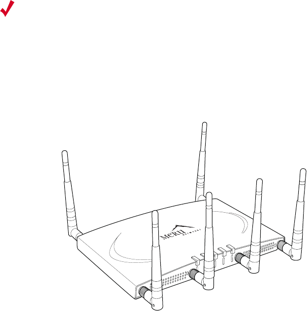
Mount AP300 Horizontally
When mounting an AP300 horizontally, remove the mounting bracket. Be sure to position the
antennas vertically when an AP300 sits on a surface. See Figure 6.
antenna
connector
Caution!
When changing the orientation of the antennas, be sure to slightly loosen the
knurled ring before moving the antenna. Retighten the ring afterward. Otherwise, you might
damage the internal cabling in the AP.
10 Meru AP300 Guide © 2007 Meru Networks, Inc.
Install the Access Points
Figure 6: Horizontal AP300
Mount AP300 on a Wall
Note:
If you are replacing AP150s, you can use the existing brackets: the AP150 and AP300
use the same bracket. If you are replacing AP200s, the AP300 bracket can be attached to the
old bracket with shoulder screws (see Appendix A); you don’t have to remove the old brackets.
The AP300 ships with the mounting bracket attached. To mount an AP300 on a wall:
1. Using the bracket holes as a guide, mark the location on the wall for the two AP bracket
mounting screws. If possible, center the mounting screws on a wall stud. If you do not
center the mounting screws on a wall stud, use plastic wall anchors.
2. Drill holes at the locations you marked:
—3/16-inch holes if you are using plastic anchors
—1/8-inch holes if you are using only the screws
3. If you are using plastic anchors, install them in the holes.
4. Screw in the screws most of the way.
5. Mount the bracket on the screws, placing the circular portion of the keyhole mounts over
the screw heads and sliding the bracket down.
6. Connect one end of the Ethernet cable to the AP300 Ethernet port shown in Figure 7.
A
2
A
2
A
L
A
N
R
F
1
R
F
2
2
00207
Check AP300 LED Activity
© 2007 Meru Networks, Inc. Installing the AP300 11
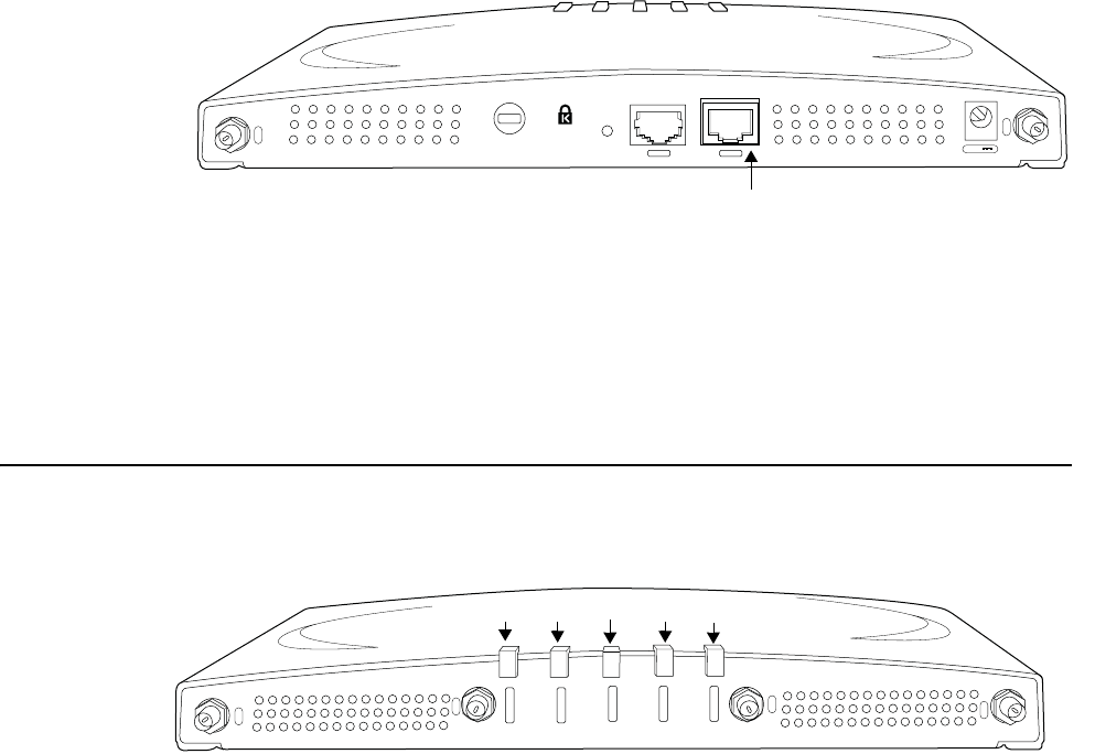
Figure 7: Connect AP300 to LAN
7. Either connect an external power supply to the power connector and plug it into the wall,
or connect an appropriate PoE power device to the Ethernet port (see Figure 7).
Check AP300 LED Activity
After the AP300 is connected, the LEDs should light (see Figure 8).
Figure 8: AP300 Status LEDs
The functions of the five LEDs are described in Table 5.
When the AP300 is first connected to the controller and any time the access point is rebooted
thereafter, the AP initializes with and then is programmed by the controller. When the AP is
first powered up, all LEDs are green. Thereafter, the Status LED (see Figure 8) color reflects
the various operating states (Table 5).
A
5
A
6
5V DC
CON LAN
00209
Ethernet Port
A
5
A
4
A
3
A
3
P
W
R
S
T
A
T
L
A
N
R
F
1
R
F
2
00208
power status LAN RF1 RF2

12 Meru AP300 Guide © 2007 Meru Networks, Inc.
Configure AP300 Software
Table 5: AP300 LED Descriptions
Configure AP300 Software
You can configure both the power source the AP300 will use and the channel width the AP300
will use. The default power source is 802.3af, and the default channel width is 20 MHz; these
are the lowest (and slowest) settings. Increase range and throughput by changing MIMO mode
to 3x3. The power supply option that you select determines whether or not you can use 3x3
MIMO. Be sure to change the power supply setting to either a DC power supply (provided) or a
802.11at PoE before changing MIMO mode to 3x3.
Configure AP300 Using the CLI
Use the CLI command configure ap to set the Power Supply Type and configure interface
Dot11Radio to set the Channel Width, and MIMO Mode. For example:
1. Access the controller from a browser by entering the IP address of the controller.
2. Switch to configuration mode by entering terminal configuration at the CLI prompt. The
prompt changes to controller name (config).
3. Select an AP by entering the command ap #. For example:
LED Function
Power off—no power
green—presence of power
Status
off—no power
green—booting stage 1
blinking green and off—booting stage 2
blinking green and white—discovering the controller
blinking green and blue—downloading a configuration from the controller
blinking blue and off—AP is online and enabled, working state
blinking red and yellow—failure; consult controller for alarm state
LAN
off—no power, or no link
green—link status OK (at any speed)
green/blinking—activity (at any speed)
red—auto negotiation failure
Radio 1
Radio 2
off—no radio present
green—radio enabled
green blinking—data activity
yellow—disabled or in scanning mode
red—failure
Configure AP300 Software
© 2007 Meru Networks, Inc. Installing the AP300 13
default(config)# ap 1 *******changes to ap config****
default(config-ap)# ? *******help lists options****
boot-script Configure boot script for this AP.
building Building location for this AP.
connectivity Manage AP connectivity.
contact Contact person for this AP.
dataplane-mode Determine whether the data packets go through the
controller or not.
default Reset to default values
description Description of AP.
do Executes an IOSCLI command.
end Save changes, and return to privileged EXEC mode.
exit Save changes, and return to global configuration mode.
floor Floor location for this AP.
high-density-enable Enable high density.
led Configure LED settings.
link-probing-duration Duration AP waits before rebooting when
controller link is down.
location Location of this AP.
mac-address Assign a new MAC address or pre-provision AP.
model Assign AP HW type.
no Disables various parameters.
power-supply Power Supply mode for this AP.
show Displays various parameters related to this AP.
4. Set the power supply with the CLI command power supply. For example:
default(config-ap)# power-supply ? *******help lists options****
5V-DC 5V-DC for AP Power.
802.3-af 802.3af Power Over Ethernet.
802.3-at 802.3-at Power Over Ethernet.
dual-802.3-af dual-802.3-af Power Over Ethernet.
default(config-ap)# power-supply 5V-DC ***changes power to 5V***
5. Exit configuration mode with the CLI command exit.\
6. Switch to radio channel configuration with the CLI command interface Dot11Radio #
#. For example:
default(config-ap)# exit
default(config)# interface Dot11Radio 1 1 ***switches to radio channel
config***
default(config-if-802)# ? ****help lists options*****
admin-mode Administrative Mode.
antenna-property Manage external wireless interface antennas.
antenna-selection Antenna configuration.
channel Configure the channel ID.
channel-width Configure the Channel Width for 802.11n
default Set various parameters to the default value.
do Executes an IOSCLI command.
end Save changes, and return to privileged EXEC
mode.
exit Save changes, and return to global configuration
mode.
fixed-channel Fix channel so it cannot be changed by auto-
channel configuration.
mimo-mode Configure the MIMO mode
14 Meru AP300 Guide © 2007 Meru Networks, Inc.
Configure AP300 Software
mode AP mode configuration.
no Disables various parameters.
power Transmit power in the format low,medium,high.
For example, 20,20,20.
preamble-short Enables short preamble.
protection-cts-mode B/G protection mechanism.
protection-mode bg protection mode.
rf-mode Configure the Radio Frequency mode (802.11a, b,
g, bg, an
, or bgn).
show Displays various parameters related to this
wireless interface.
7. Change channel width from 20 MHz (default) to 40 MHz with the CLI command channel-
width. For example:
default(config-if-802)# channel-width ? ***help shows options***
20-mhz 20 MHz.
40-mhz-extension-channel-above 40 MHz Extension channel above.
40-mhz-extension-channel-below 40 MHz Extension channel below.
default(config-if-802)# channel-width above 40 MHz Extension channel
****changes channel width****
8. Change MIMO Mode from 2x2 (default) to 3x3 with the mimo-mode 3x3 command. For
example:
default(config-if-802)# mimo-mode 3x3 *****changes MIMO ****
default(config-if-802)# end
default#
default
Configure AP300 Using the GUI
Follow these steps to change Power Supply Type, Channel Width, and MIMO Mode using the GUI:
1. Enter the IP address of the controller in your browser. You see the controller GUI interface.
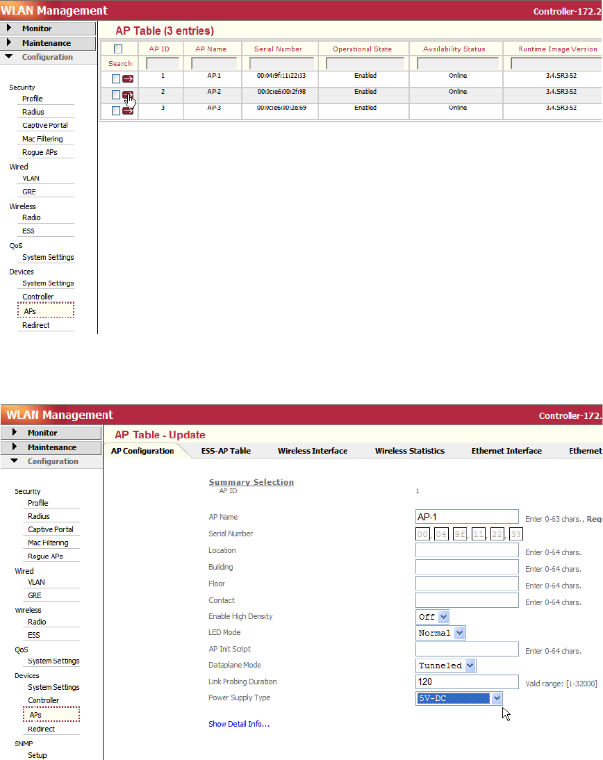
2. From the controller GUI, click Configuration > Devices > APs. The AP Table shown in
Figure 9 is displayed.
Configure AP300 Software
© 2007 Meru Networks, Inc. Installing the AP300 15
Figure 9: AP Table Configuration Window
3. Click the arrow that corresponds to the AP300 to change. The AP configuration for that AP
is displayed. See Figure 10.
Figure 10: Changing Power Supply Type
4. Click the Power Supply Type drop-down list and select one of the following options. The
included DC power block corresponds to the option 5V DC.
16 Meru AP300 Guide © 2007 Meru Networks, Inc.
Configure AP300 Software
—802.3-af: Default power supply. Select this when using a traditional PoE. This power
supply type only supports 2x2 MIMO mode.
—802.3-at: Select when using a higher-powered, next generation PoE. This power supply
type supports 3x3 MIMO mode.
—5V-DC: Select when AP300 is plugged into a wall outlet. This power supply type supports
3x3 MIMO mode.
—dual-802.3: Select when using a dongle that combines power from two traditional PoEs.
This power supply type supports 3x3 MIMO mode.
5. Click OK.
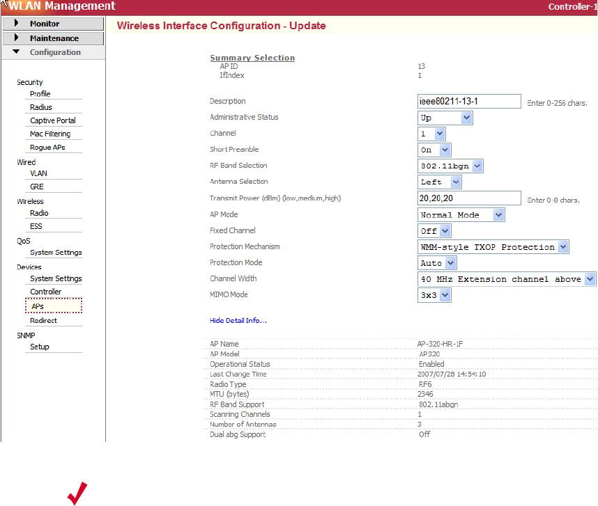
6. Next, configure MIMO mode and Channel Width. Click the Wireless Interface tab. You see
the Wireless Interface Configuration window shown in Figure 11.
Figure 11: Wireless Interface Tab - Set MIMO Mode and Channel Width
7. Configure RF Band Selection by selecting a value from the drop-down list. To configure the
band as N only, select a setting that includes N and change the data rates setting to make
only N viable.
8. Configure MIMO mode by clicking the drop-down list and selecting either 2x2 or 3x3. Be
sure you have already configured an appropriate power source for 3x3 MIMO Mode. 3x3
MIMO Mode produces higher reliability, range, and speed but both settings (2x2 and 3x3)
should approach 320 mbps.
Note:
The Short Preamble Setting affects 11b clients only. The Protection
Mechanism setting has no effect at this time.

Troubleshooting
© 2007 Meru Networks, Inc. Installing the AP300 17
9. Configure Channel Width by clicking the drop-down list and selecting either 40 MHz
Extension channel above or 40 MHz Extension channel below. The ‘channel above’ and
‘channel below’ are relative to the value set in the Channel control setting (see
Figure 11, the third setting from the top). This configures the channel bonding.
10. Click OK.
Troubleshooting
zIf an AP320 continually reboots or demonstrates other unusual behavior, and MIMO Mode is
set to 3x3, there may be a mismatch of power and MIMO Mode. Make sure that you have an
appropriate power source configured, as well as attached to an AP320 with MIMO Mode set
to 3x3.
zWhen RF band selection is set to 802.11n, the security mode can only be set at clear, wpa2
or wpa2psk. This is an 802.11n restriction.
zThe ChannelWidth field value 40 Mhz-extension-channel-above is only applicable if the
extension channel above is available in the country code. For example,
A_EXT_CHANNELS=36:40 case, 40 Mhz-extension-channel-above configuration is valid for
channel number 36. Currently we support extension channels in only the US country code.
In addition, the default channel numbers for RF mode BG or A mode are changed in the US
country code (DEFAULT_B_CHANNEL=6, DEFAULT_A_CHANNEL=36).
18 Meru AP300 Guide © 2007 Meru Networks, Inc.
Troubleshooting
© 2007 Meru Networks, Inc. AP300 Brackets 19
Appendix A
AP300 Brackets
The AP300 is designed to be used with brackets supplied by other vendors. Meru APs are
compatible with the Cisco 1230 series brackets, but the 1240 and 1250 series brackets are new
and not compatible. If you reuse a Cisco 1230 series bracket, follow these steps:
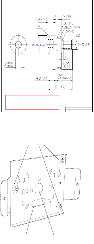
1. Obtain three of the screws shown in Figure 12.
Figure 12: Shoulder Screw (specification front and side)
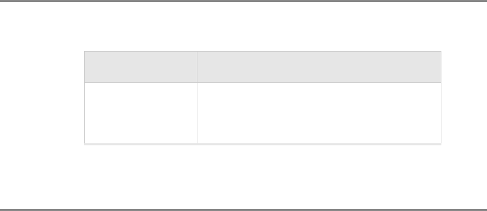
2. Insert the three screws into the locations indicated in Figure 13.
U
SI PN 48-300024-01
D
escription: UNC#10-32,1/4*1/8,HS,BND,303SS,NO,SHOLD
R
D
OC NO:2A-003225
R
EV: A1
D
ATE: 7th July 2005
Suspended ceiling
cable access
Wall cable access
Shoulder screws
20 Meru Access Point and Radio Switch Installation Guide © 2007 Meru Networks, Inc.
Figure 13: Location of Shoulder Screws
3. Slide the Meru bracket with shoulder screws onto the Cisco bracket.

© 2007 Meru Networks, Inc. Specifications 21
Appendix B
Specifications
This chapter provides specifications for Meru Access Points and contains the following
sections:
zWireless Interface for All APs
zEthernet Interface for All Meru APs
zPhysical Description for All Meru APs
Wireless Interface for All Meru APs
Table 6: Wireless Interface Specifications
Feature Details
Wireless Standards z802.11a, 802.11b, 802.11g, 802.11n
Antennas zTwo to six external antennas. Omni-directional and direc-
tional antennas for specific coverage requirements
Wireless Medium
Access
zWi-Fi Compliant 802.11 MAC standard
Power Management zPower-save mode for clients in both QoS mode and non-
QoS mode
Frame Size
zPeak frame size of > 2346 bytes
zFragmentation and reassembly of 802.11/Ethernet
frames
Client Activities Sup-
ported
zActive scanning and passive scanning
zPre-authentication
zPower-save mode supported
22 Meru Access Point and Radio Switch Installation Guide © 2007 Meru Networks, Inc.
Ethernet Interface for All Meru APs
Ethernet Interface for All Meru APs
Physical Description for All Meru APs
Physical specifications for Meru Access Points are provided in the access point Data
Sheet. Contact your Meru sales engineer for a copy of the document.
Feature Detail
Wireline Standard
zOne Ethernet (IEEE 802.3) interface, supporting
half-duplex and full-duplex modes
zSupports the Power over Ethernet (PoE) IEEE
802.3af standard

© 2007 Meru Networks, Inc. Regulatory Information 23
Appendix C
Regulatory Information
The Meru Networks, Inc. Meru Access Points (APs) must be installed and used in strict
accordance with the manufacturer’s instructions as described in the user documen-
tation that comes with the product. For country-specific approvals, see below. Meru
Networks, Inc. is not responsible for any radio or television interference caused by
unauthorized modification of APs, or the substitution or attachment of connecting
cables and equipment other than that specified by Meru Networks, Inc. The correc-
tion of interference caused by such unauthorized modification, substitution or
attachment is the responsibility of the user. Meru Networks, Inc. and its authorized
resellers or distributors are not liable for any damage or violation of government
regulations that may arise from the user failing to comply with these guidelines.
USA — Federal Communications Commission
(FCC)
FCC Radiation Exposure Statement
Caution!
The radiated output power of the Meru Networks, Inc. devices is well
below the FCC radio frequency exposure limits. However, the Meru Net-
works, Inc. Meru Access Points should be used in such a manner that the
potential for human contact during normal operation is minimized. To
avoid the possibility of exceeding the FCC radio frequency exposure limits,
you should keep a distance of at least 20 cm between you (or any other
person in the vicinity) and the Access Point antennas.

24 Meru Access Point and Radio Switch Installation Guide © 2007 Meru Networks, Inc.
USA — Federal Communications Commission (FCC)
Radio Frequency Interference Requirements
Interference Statement
These devices comply with Part 15 of the FCC Rules. Operation of the devices is
subject to the following two conditions: (1) The devices may not cause harmful inter-
ference, and (2) The devices must accept any interference that may cause undesired
operation.
This equipment has been tested and found to comply with the limits for a Class B
digital device, pursuant to Part 15 of the FCC Rules. These limits are designed to
provide reasonable protection against harmful interference in a residential installa-
tion. This equipment generates, uses, and can radiate radio frequency energy. If the
equipment is not installed and used in accordance with the instructions, the equip-
ment may cause harmful interference to radio communications. There is no guar-
antee, however, that such interference will not occur in a particular installation. If
this equipment does cause harmful interference to radio or television reception
(which can be determined by turning the equipment off and on), the user is encour-
aged to try to correct the interference by taking one or more of the following
measures:
Relocate this device.
Increase the separation between the device and the receiver.
Connect the device into an outlet on a circuit different from that of other
electronics.
Consult the dealer or an experienced radio technician for help.
This device must not be co-located or operating in conjunction with any other
antenna or transmitter.
Note:
Meru Networks Meru Access Point
These devices are restricted to indoor use because they operate in the
5.15 to 5.25 GHz frequency range. The FCC requires such products to be
used indoors for the frequency range 5.15 GHz to 5.25 GHz to reduce the
potential for harmful interference to co-channel Mobile Satellite systems.
Note:
The Meru Networks Meru Access Point must be installed and used in strict
accordance with the manufacturer’s instructions as described in the user
documentation that comes with the product. Any other installation or use
may violate FCC Part 15 regulations. Modifications not expressly approved
by Meru Networks, Inc. could void your authority to operate the equip-
ment.

Canada. Industry Canada (IC)
© 2007 Meru Networks, Inc. Regulatory Information 25
Canada. Industry Canada (IC)
This device complies with RSS210 of Industry Canada.
Operation is subject to the following two conditions: (1) this device may not cause
interference, and (2) this device must accept any interference, including interfer-
ence that may cause undesired operation of this device.
L’utilisation de ce dispositif est autorisée seulement aux conditions suivantes: (1) il
ne doit pas produire de brouillage et (2) l’utilisateur du dispositif doit étre prêt à
accepter tout brouillage radioélectrique reçu, même si ce brouillage est susceptible
de compromettre le fonctionnement du dispositif.
The term "IC" before the equipment certification number only signifies that the
Industry Canada technical specifications were met.
To reduce the potential radio interference to other users, the antenna type and gain
should be chosen so that the equivalent isotropically radiated power (EIRP) is not
more than that required for successful communication.
To prevent radio interference to the licensed service, this device is intended to be
operated indoors and away from windows to provide maximum shielding. Equipment
(or its transmit antenna) that is installed outdoors is subject to licensing.
Pour empecher que cet appareil cause du brouillage au service faisant l’objet d’une
licence, il doit etre utilze a l’interieur et devrait etre place lin des fenetres afin de
Fournier un ecram de blindage maximal. Si le matriel (ou son antenne d’emission) est
installe a l’exterieur, il doit faire l’objet d’une licence.
Caution!
Exposure to Radio Frequency Radiation.
The installer of this radio equipment must ensure that the antenna is
located or pointed such that it does not emit an RF field in excess of
Health Canada limits for the general population; consult Safety Code 6,
obtainable from Health Canada’s website http://www.hc-sc.gc.ca/rpb.
Note:
Meru Networks Meru Access Points
These devices are restricted to indoor use because they operate in the
5.15 to 5.25 GHz frequency range. Industry Canada requires such products
to be used indoors for the frequency range 5.15 GHz to 5.25 GHz to reduce
the potential for harmful interference to co-channel Mobile Satellite sys-
tems.

© 2007 Meru Networks, Inc. Channels 27
Appendix D
Channels
B-1
This appendix provides the access point radio channels supported by the world’s
regulatory domains.
IEEE 802.11a
The channel identifiers, channel center frequencies, and regulatory domains of each
IEEE 802.11a 20-MHz-wide channel are listed in Table 7.
Table 7: IEEE 802.11a Channels
Channel
Number
Frequency in
MHz
Regulatory Domains
Americas Japan
34 5170 - X
36 5180 X -
38 5190 - X
40 5200 X -
42 5210 - X

28 Meru Access Point and Radio Switch Installation Guide © 2007 Meru Networks, Inc.
IEEE 802.11b/g
The channel identifiers, channel center frequencies, and regulatory domains of each
IEEE 802.11b/g channel are listed in Table 8.
44 5220 X -
46 5230
48 5240
52 5260
56 5280
60 5300
64 5320
149 5745 X -
153 5765 X -
157 5785 X -
161 5805 X -
165 5825 X -
Table 7: IEEE 802.11a Channels (Continued)
Channel
Number
Frequency in
MHz
Regulatory Domains
Americas Japan
Note:
Mexico is included in the Americas regulatory domain; however, channels 1
through 8 are for indoor use only while channels 9 through 11 can be used
indoors and outdoors. Users are responsible for ensuring that the channel
set configuration complies with the regulatory standards of Mexico.

© 2007 Meru Networks, Inc. Channels 29
Table 8: IEEE 802.11b/g Channels
Channel
Number
Frequency
in MHz
Regulatory Domains
Americas EMEA Israel China Japan
1 2412 X X
2 2417 X X
3 2422 X X
4 2427 X X
5 2432 X X
6 2437 X X
7 2442 X X
8 2447 X X
9 2452 X X
10 2457 X X
11 2462 X X
12 2467 - X
13 2472 - X
14 2484 -
X
(for 802.11b
only)

30 Meru Access Point and Radio Switch Installation Guide © 2007 Meru Networks, Inc.
IEEE 802.11n
The channel identifiers, channel center frequencies, and regulatory domains of each
IEEE 802.11b/g channel are listed in Table 9.
Table 9: IEEE 802.11n Channels
Channel
Number
Frequency
in MHz Regulatory Domains
North
America ETSI
I
s
r
a
e
l
Japan
(-P) China
1 2412 X X
2 2417 X X
3 2422 X X
4 2427 X X
5 2432 X X
6 2437 X X
7 2442 X X
8 2447 X X
9 2452 X X
10 2457 X X
11 2462 X X
12 2467 - X

© 2007 Meru Networks, Inc. Channels 31
13 2472 - X
14 2484 -
36 5180 X X
40 5200 X X
44 5220 X X
Channel
Number
Frequency
in MHz Regulatory Domains
North
America ETSI
I
s
r
a
e
l
Japan
(-P) China
149 5745 X - - X
153 5765 X - - X
157 5785 X - - X
161 5805 X - -- X

33
MERU NETWORKS, INC.
Limited Product Warranty
This Limited Product Warranty applies to the original end-user customer of the Meru product which you
purchased for your own use, and not for resale (“Product”), from Meru Networks, Inc. (“Meru”) or its
authorized reseller (“Reseller”).
Limited Warranties
—One-year limited hardware warranty: Meru warrants to you that Meru hardware (other than Third
Party Products as described below) will be free from defects in materials and workmanship for a
one-year period after the date of delivery of the applicable product to you from Meru or its
Reseller (the “Hardware Warranty Period”). If Meru receives written notice from you of such
defects during the Hardware Warranty Period, Meru will, at its option, either repair or replace
Meru hardware that Meru determines to be defective. Replacement products may be remanufac-
tured units, and will be warranted for the remainder of the original Hardware Warranty Period, or
if greater, for thirty days from delivery of such replacement. Should Meru be unable to repair or
replace the Meru hardware, Meru (or its Reseller, as applicable) will refund to you the purchase
price of the Product.
—90-Day Limited Software Warranty: Meru warrants to you that, for a 90-day period after the date
of delivery of the applicable product to you from Meru or its Reseller (the “Software Warranty
Period”), when properly installed and used, (a) the media on which the Meru software is provided
will be free from defects in materials or workmanship; and (b) the Meru software will substantially
conform to the functional specifications in the applicable documentation. If Meru receives written
notice from you of a breach of this warranty during the Software Warranty Period and is able to
reproduce the defect, Meru will, at its option, either repair or replace the defective Meru software.
Should Meru be unable to repair or replace the Meru software, Meru (or its Reseller, as applicable)
will refund to you the purchase price of the Product.
Exclusions
The warranty on the Product shall not apply to defects resulting from the following:
—Alteration or modification of the Product in any way, including without limitation configuration
with software or components other than those supplied by Meru or integration with parts other
than those supplied by Meru.
—Abuse, damage or otherwise being subjected to problems caused by negligence or misapplication
(including without limitation improper or inadequate maintenance or calibration), relocation of
the products (including without limitation damage caused by use of other than Meru shipping
containers), or use of the products other than as specified in the applicable Meru product docu-
mentation (including without limitation incompatible operating environments and systems), or
improper site preparation or maintenance.
—Damage as a result of accidents, extreme power surge, extreme electromagnetic field, acts of
nature or other causes beyond the control of Meru.
—Use of the Product with software, interfacing, parts or supplies not supplied by Meru.
The warranty on the Product does not apply if the Product is sold, or in the case of software, licensed,
for free for evaluation or demonstration purposes.
34 Meru Access Point and Radio Switch Installation Guide
Meru expressly disclaims any warranty or obligation to support the Product for all operating
environments – for example, as illustration and not limitation, Meru does not warrant or
ensure interoperability of the Product with future telecommunication systems or other future
software or hardware.
You understand and acknowledge that the Products may generate, use or radiate radio
frequency energy and may interfere with radio communications and/or radio and television
receptions if is not used and/or installed in accordance with the documentation for such
products. WHILE MERU USES COMMERCIALLY REASONABLE EFFORTS TO
ENSURE COMPLIANCE OF THE PRODUCTS WITH APPLICABLE UNITED STATES
FEDERAL COMMUNICATIONS COMMISSION AND PROTECT AGAINST HARMFUL
INTERFERENCES, YOU ACKNOWLEDGE AND AGREE THAT INTERFERENCES
WITH RADIO COMMUNICATIONS AND/OR RADIO AND TELEVISION
RECEPTIONS MAY OCCUR AND THAT MERU WILL NOT BE LIABLE FOR ANY
DAMAGES OR INCONVENIENCE BASED ON SUCH INTERFERENCES.
Third Party Products - The above Limited Warranties are exclusive of products
manufactured by third parties (“Third Party Products”). If such third party manufacturer
provides a separate warranty with respect to the Third Party Product, Meru will include such
warranty in the packaging of the Meru Product.
Return procedures
To obtain warranty service you must: (a) obtain a return materials authorization number
(“RMA#”) from Meru by contacting support@merunetworks.com, and (b) deliver the
Product, in accordance with the instructions provided by Meru, along with proof of purchase
in the form of a copy of the bill of sale including the Product’s serial number, contact
information, RMA# and detailed description of the defect, in either its original package or
packaging providing the Product with a degree of protection equivalent to that of the original
packaging, to Meru at the address below. You agree to obtain adequate insurance to cover loss
or damage to the Product during shipment.
If you obtain an RMA# and return the defective Product as described above, Meru will pay
the cost of returning the Product to Meru. Otherwise, you agree to bear such cost, and prior
to receipt by Meru, you assume risk of any loss or damage to the Product. Meru is responsible
for the cost of return shipment to you if the Meru Product is defective.
Returned products which are found by Meru to be not defective, returned out-of-warranty or
otherwise ineligible for warranty service will be repaired or replaced at Meru’s standard
charges and shipped back to you at your expense.
At Meru’s sole option, Meru may perform repair service on the Product at your facility, and
you agree to provide Meru with all reasonable access to such facility and the Product, as
required by Meru. On-site repair service may be available and is governed by the specific
terms of your purchase.
All replaced parts, whether under warranty or not, are the property of Meru.
Warranty limitations
THE WARRANTIES SET FORTH ABOVE ARE EXCLUSIVE AND NO OTHER
WARRANTY, WHETHER WRITTEN OR ORAL, IS EXPRESSED OR IMPLIED BY
MERU, TO THE MAXIMUM EXTENT PERMITTED BY LAW. THERE ARE NO OTHER
35
WARRANTIES RESPECTING THE PRODUCT AND DOCUMENTATION AND
SERVICES PROVIDED UNDER THIS AGREEMENT, INCLUDING WITHOUT
LIMITATION ANY WARRANTY OF DESIGN, MERCHANTABILITY, FITNESS FOR A
PARTICULAR PURPOSE (EVEN IF MERU HAS BEEN INFORMED OF SUCH
PURPOSE), TITLE OR AGAINST INFRINGEMENT OF THIRD PARTY RIGHTS. IF
ANY IMPLIED WARRANTY CANNOT BE DISCLAIMED UNDER APPLICABLE LAW,
THEN SUCH IMPLIED WARRANTY SHALL BE LIMITED IN DURATION TO THE
HARDWARE AND SOFTWARE WARRANTY PERIODS DESCRIBED ABOVE.
NO AGENT OF MERU IS AUTHORIZED TO ALTER OR EXCEED THE WARRANTY
OBLIGATIONS OF MERU.
MERU SPECIFICALLY DOES NOT WARRANT THAT THE MERU SOFTWARE WILL
BE ERROR FREE OR OPERATE WITHOUT INTERRUPTION.
THE REMEDIES IN THIS LIMITED PRODUCT WARRANTY ARE YOUR SOLE AND
EXCLUSIVE REMEDIES, AND MERU’S SOLE AND EXCLUSIVE LIABILITY, FOR
BREACH OF THE HARDWARE OR SOFTWARE WARRANTY SET FORTH ABOVE.
Limitations of Liability
You acknowledge and agree that the consideration which you paid to Meru does not include
any consideration by Meru of the risk of consequential, indirect or incidental damages which
may arise in connection with your use of, or inability to use, the Product. THUS, MERU AND
ITS RESELLER WILL NOT BE LIABLE FOR ANY INDIRECT, INCIDENTAL,
SPECIAL, PUNITIVE OR CONSEQUENTIAL DAMAGES, INCLUDING WITHOUT
LIMITATION LOST PROFITS, LOST BUSINESS, LOST DATA, LOSS OF USE, OR
COST OF COVER INCURRED BY YOU ARISING OUT OF OR RELATED TO YOUR
PURCHASE OR USE OF, OR INABILITY TO USE, THIS PRODUCT OR THE
SERVICES, UNDER ANY THEORY OF LIABILITY, WHETHER IN AN ACTION IN
CONTRACT, STRICT LIABILITY, TORT (INCLUDING NEGLIGENCE) OR OTHER
LEGAL OR EQUITABLE THEORY, EVEN IF MERU OR ITS RESELLER KNEW OR
SHOULD HAVE KNOWN OF THE POSSIBILITY OF SUCH DAMAGES. IN ANY
EVENT, THE CUMULATIVE LIABILITY OF MERU OR ITS RESELLER FOR ALL
CLAIMS WHATSOEVER RELATED TO THE PRODUCT OR THE SERVICE WILL NOT
EXCEED THE PRICE YOU PAID FOR THE PRODUCT OR SERVICES GIVING RISE TO
SUCH CLAIMS.
THE LIMITATIONS SET FORTH HEREIN ARE INTENDED TO LIMIT THE LIABILITY
OF MERU AND ITS RESELLERS AND SHALL APPLY NOTWITHSTANDING ANY
FAILURE OF ESSENTIAL PURPOSE OF ANY LIMITED REMEDY.
The jurisdiction applicable to you may not allow the limitations of liability or damages set
forth above, in which case such limitation shall only apply to you to the extent permitted in
such jurisdiction.
Additional Information
This Limited Product Warranty shall be governed by and construed in accordance with the
laws of the State of California, U.S.A., exclusive of its conflict of laws principles. The U.N.
Convention on Contracts for the International Sale of Goods shall not apply.
36 Meru Access Point and Radio Switch Installation Guide
This Limited Product Warranty is the entire and exclusive agreement between you and Meru
with respect to its subject matter, and any modification or waiver of any provision of this
statement is not effective unless expressly set forth in writing by an authorized representative
of Meru.
All inquiries or claims made under this Limited Product Warranty must be sent to Meru at the
following address:
Meru Networks Inc.,
894 Ross Drive, CA 94087, USA
Tel: 408-215-5300
Fax: 408-215-5301
Email: support@merunetworks.com

Meru Networks, Inc.
894 Ross Drive
Sunnyvale, CA 94087
408-215-5300
www.merunetworks.com