Meru Networks AP332E Dual radio Access point User Manual AP300
Meru Networks Inc. Dual radio Access point AP300
UserManual.wiki
>
Meru Networks
>
AP332E User Manual
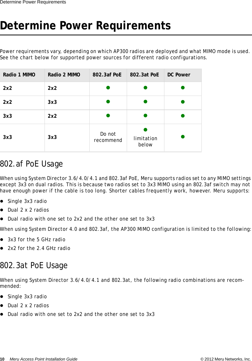
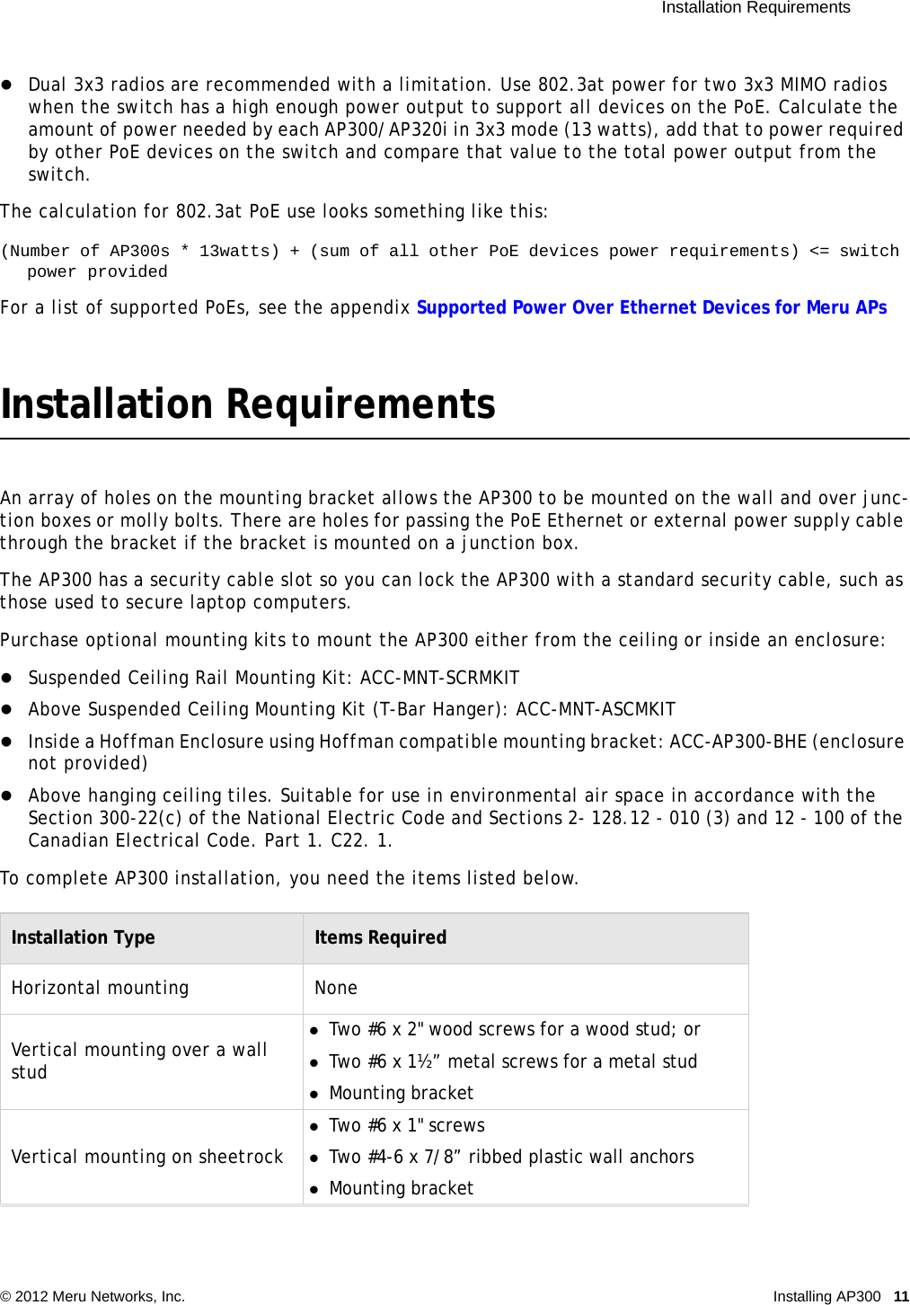
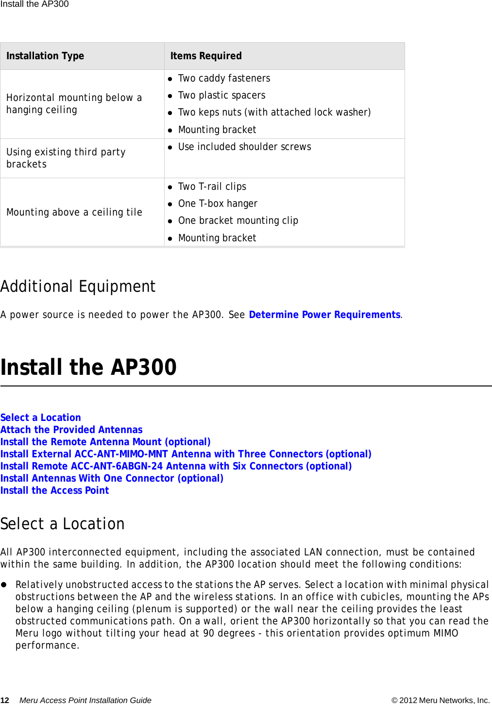
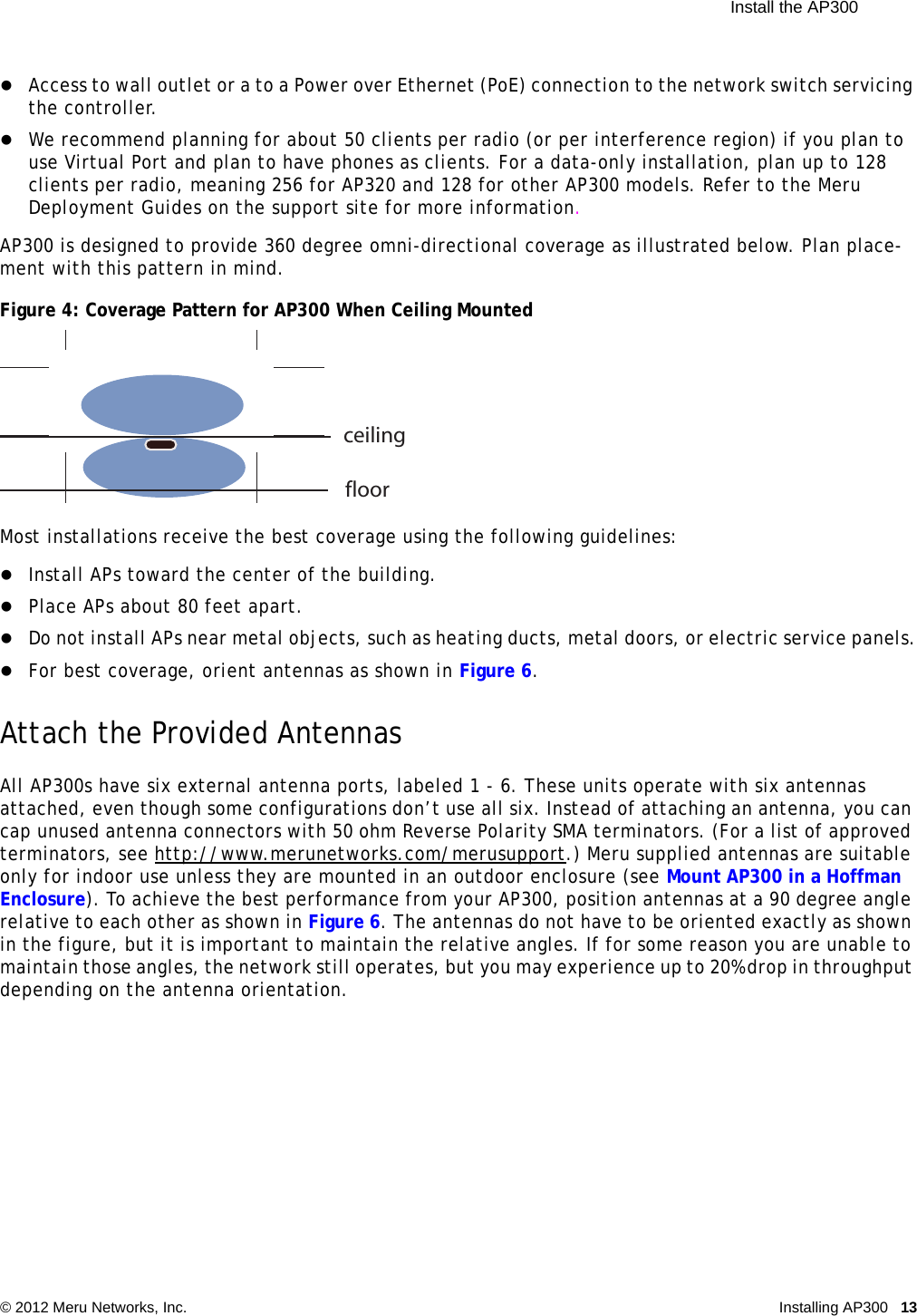
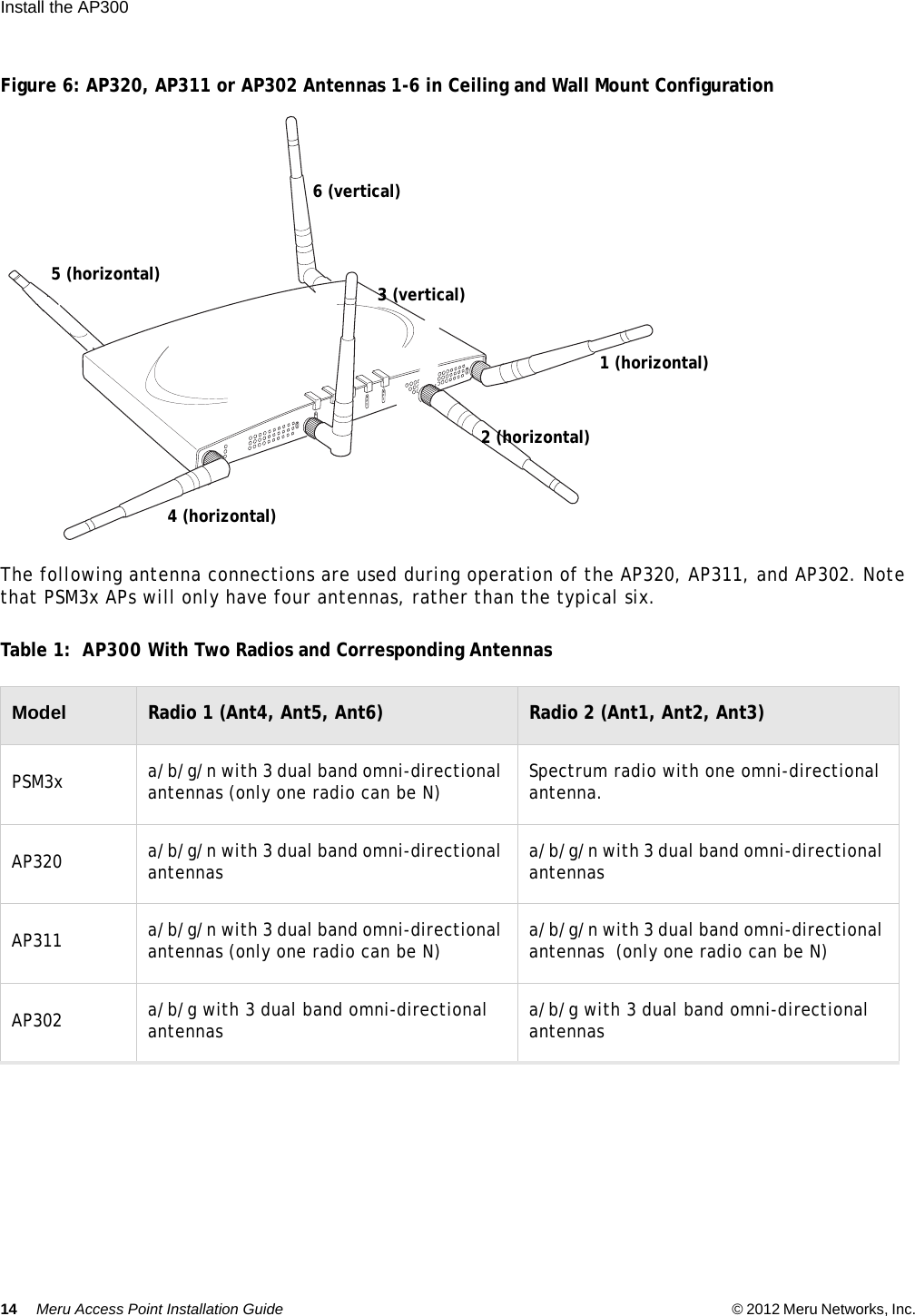
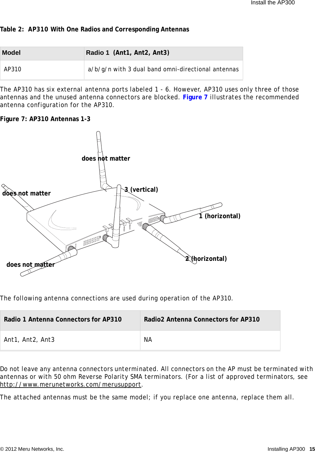
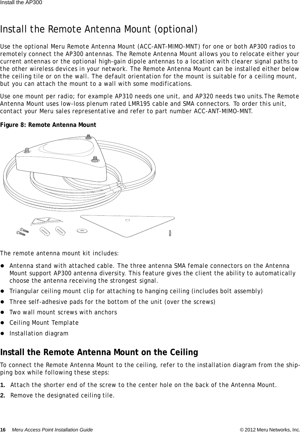
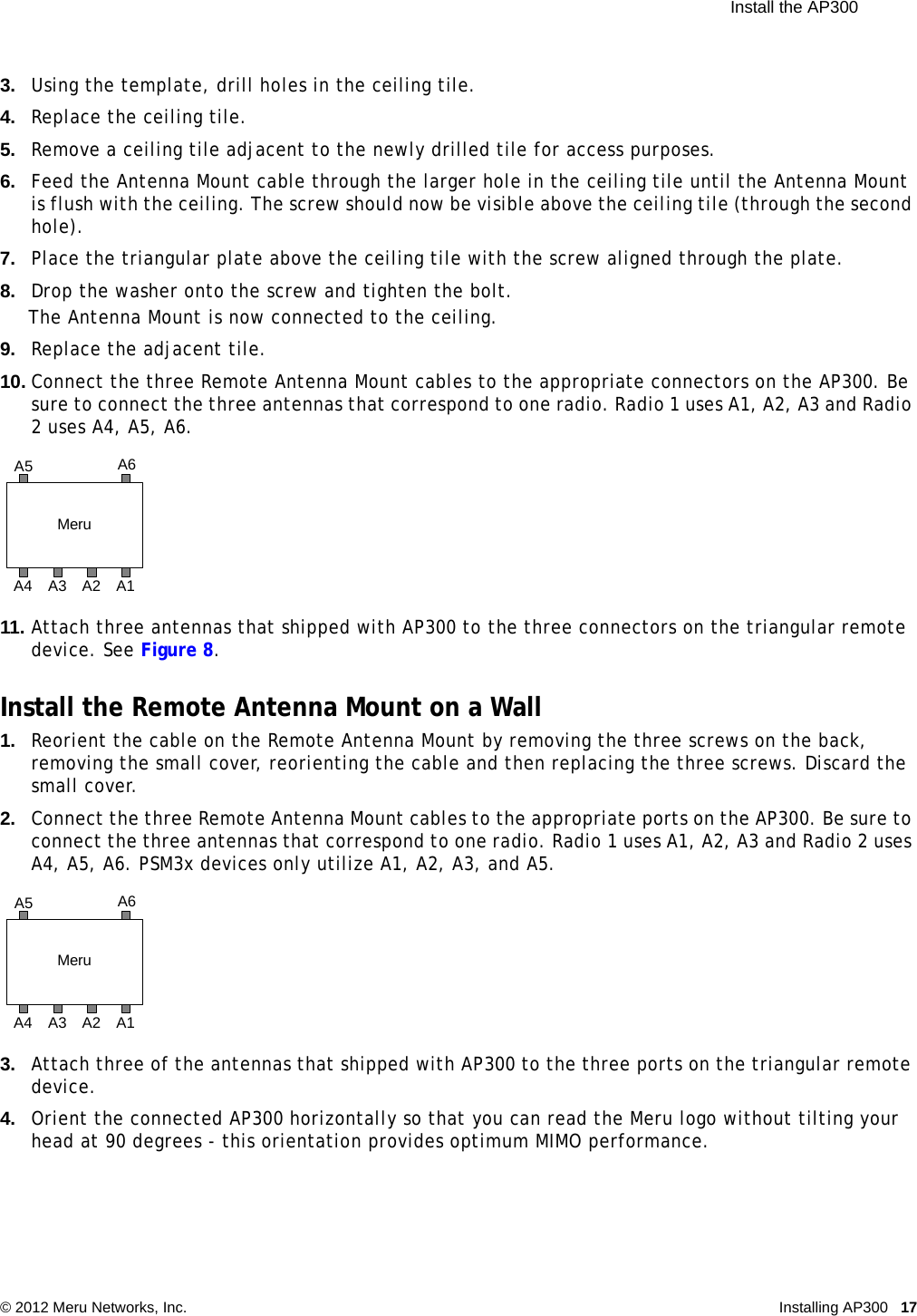
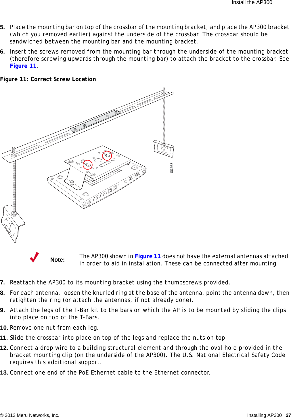
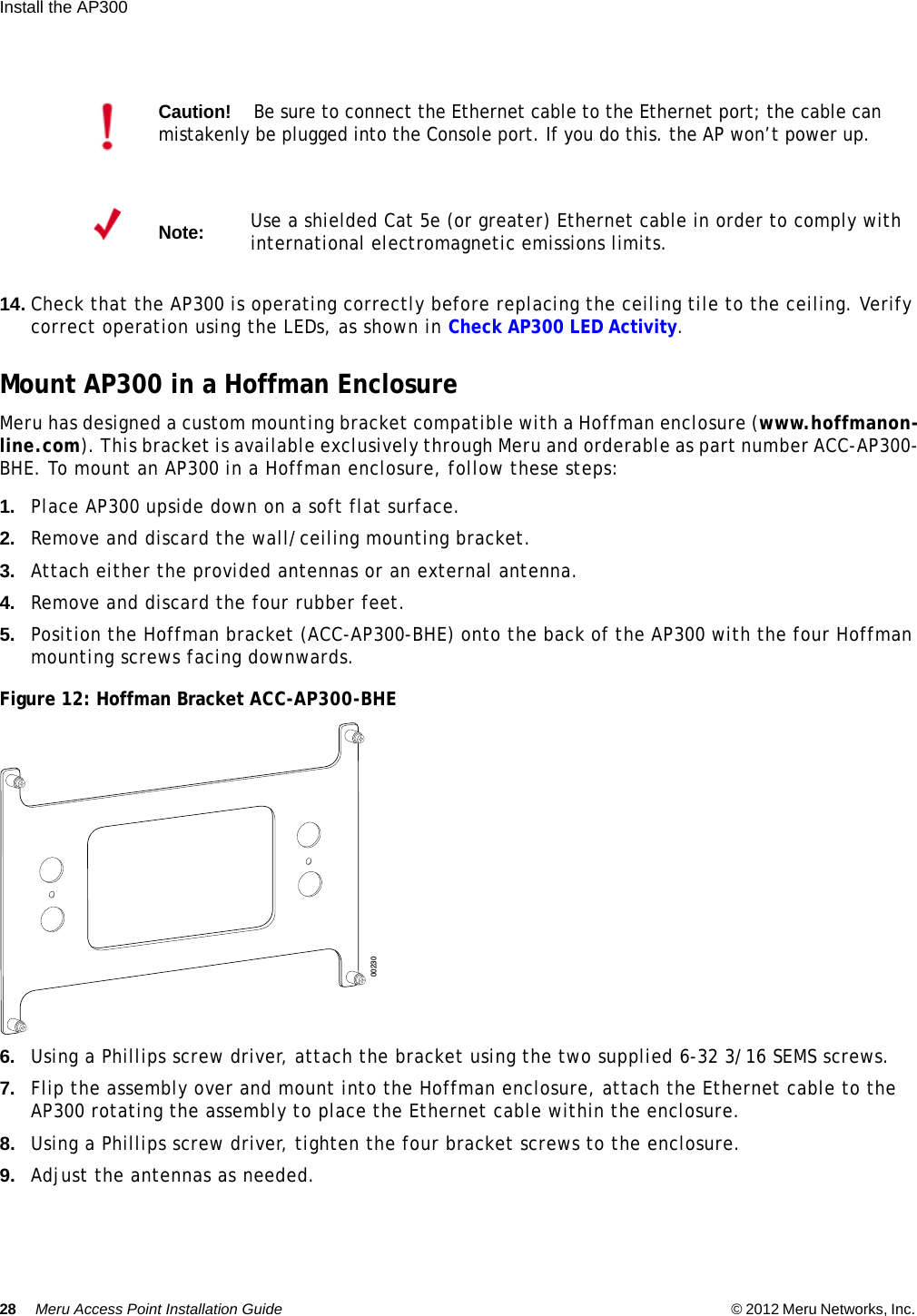
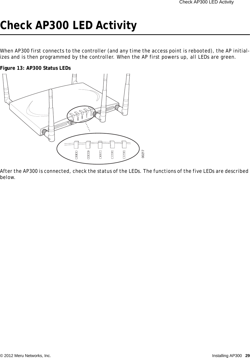
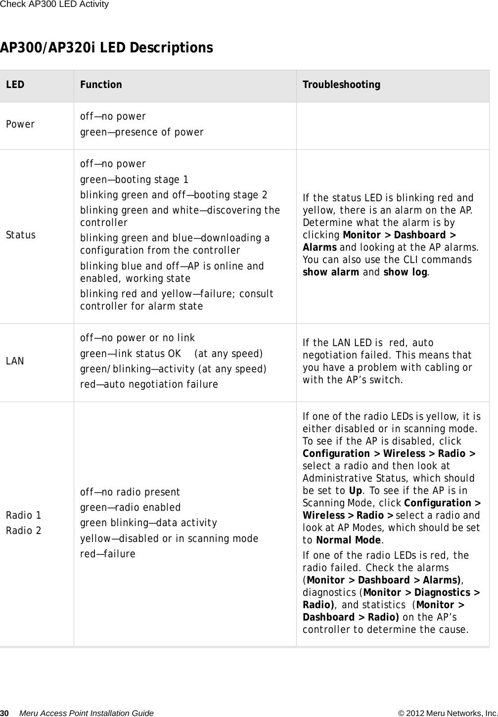
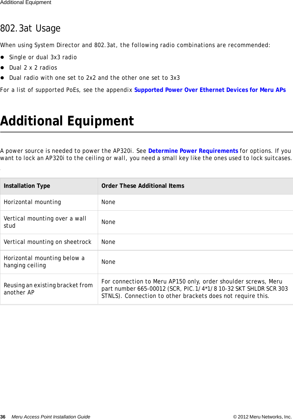
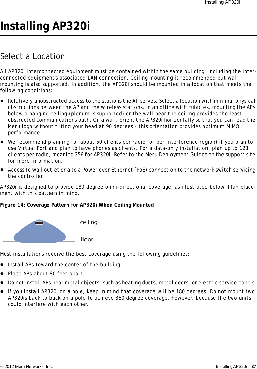
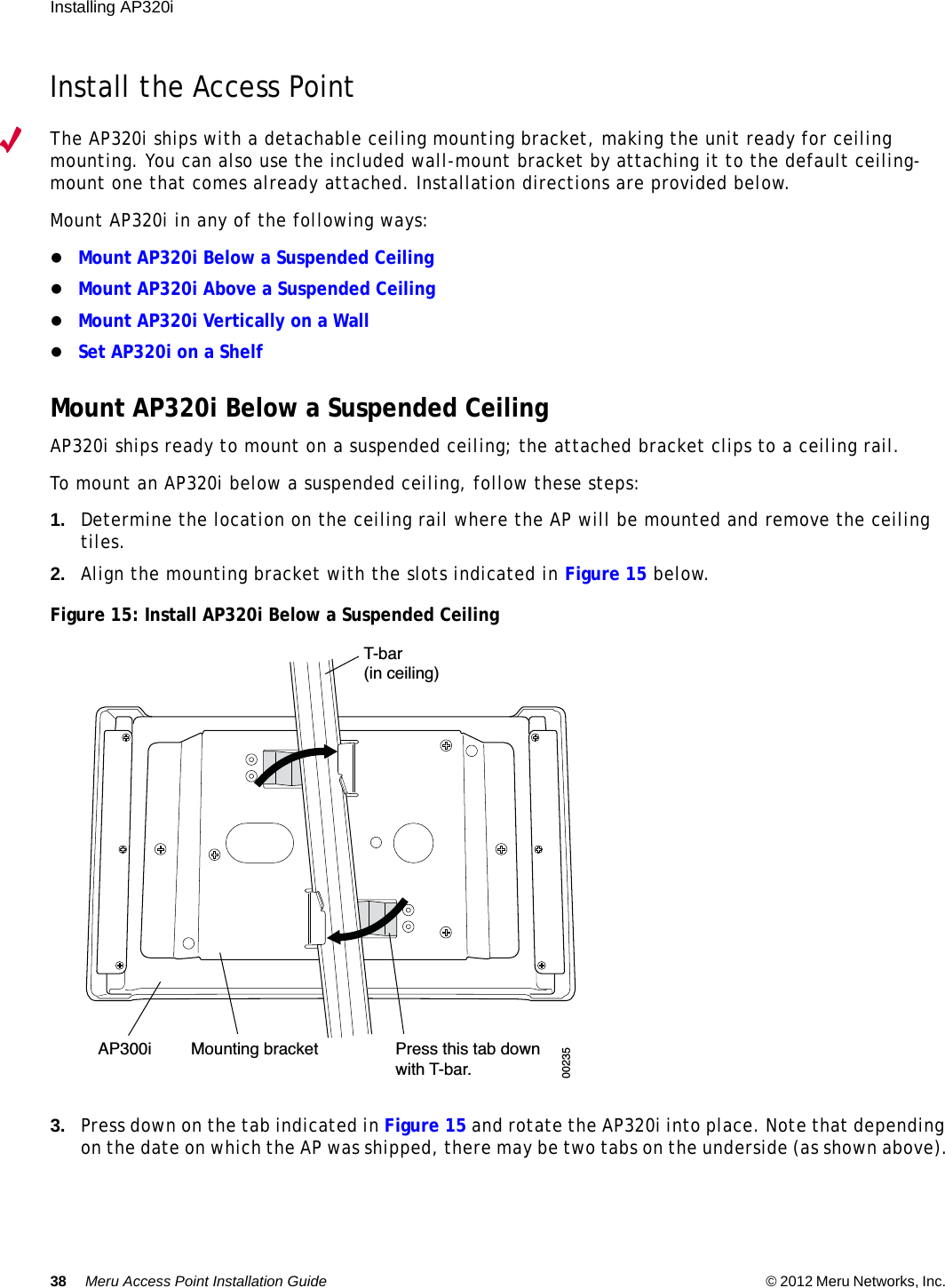
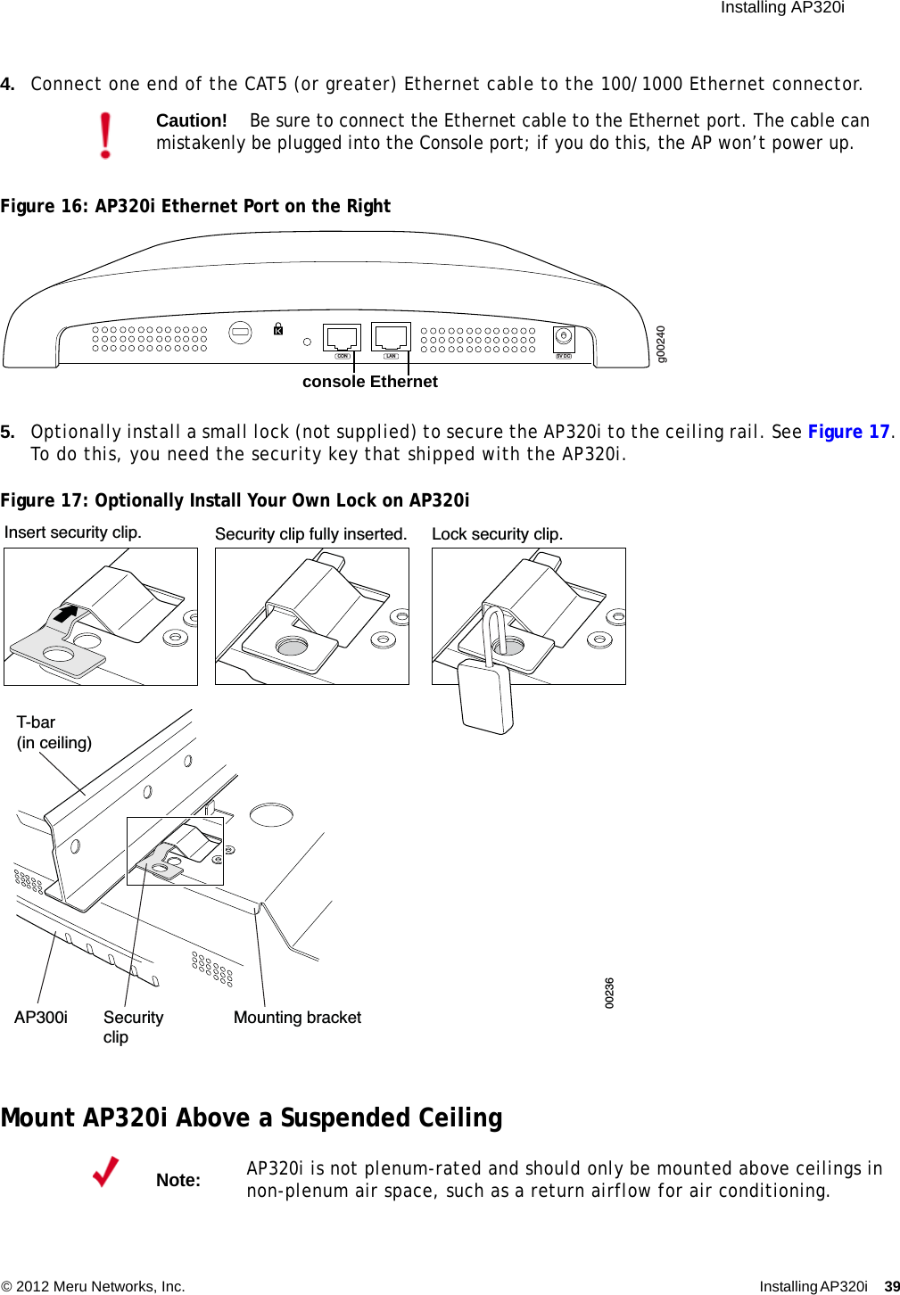
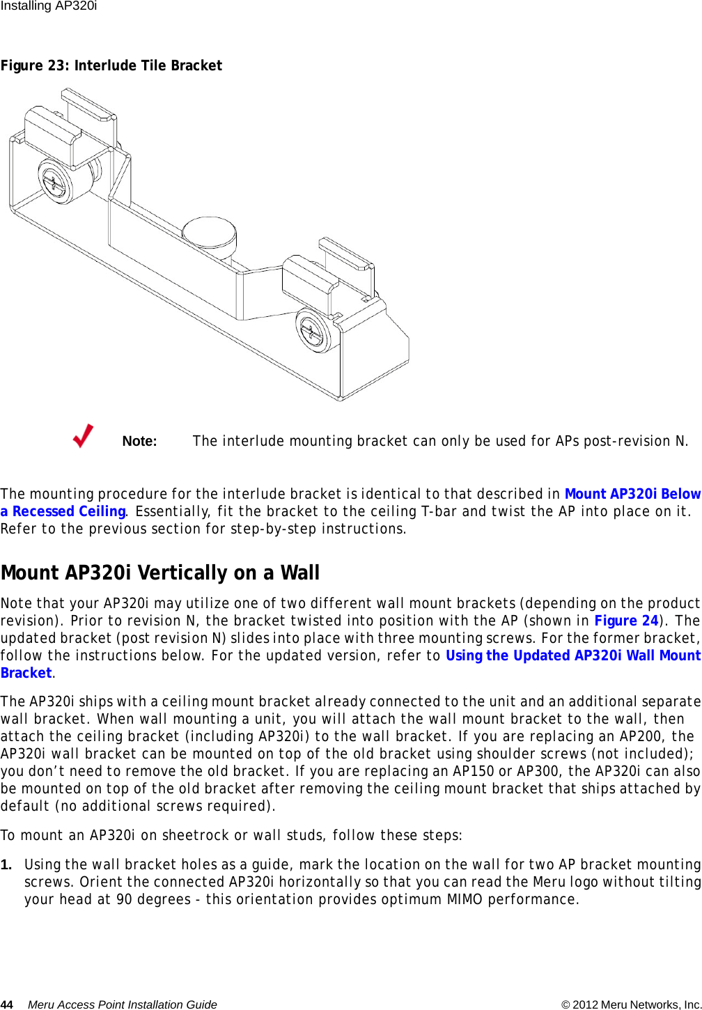
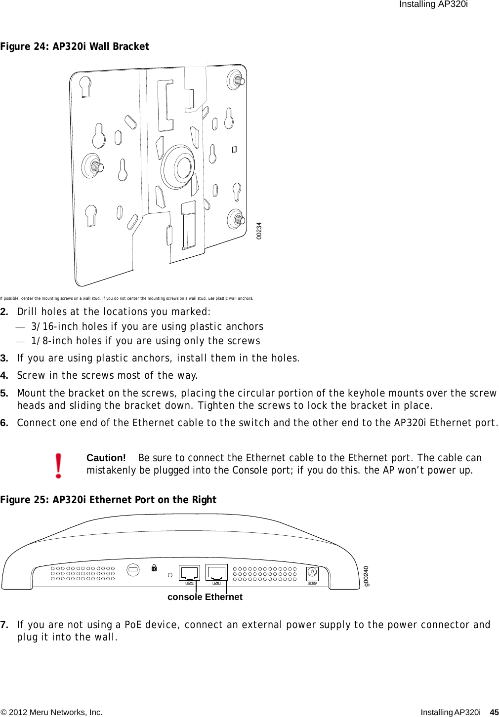
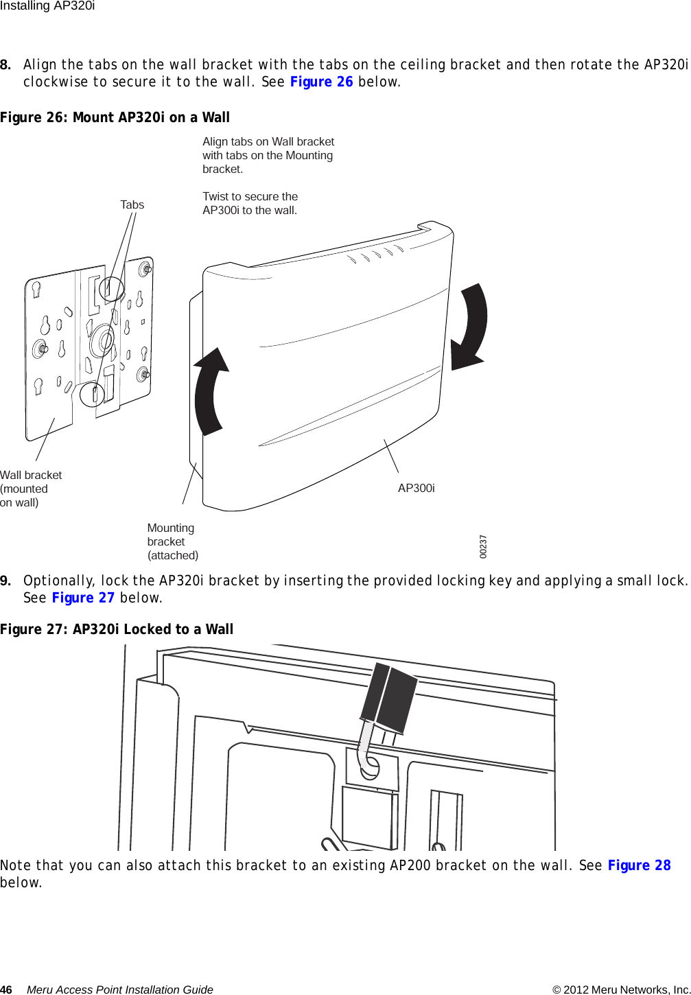
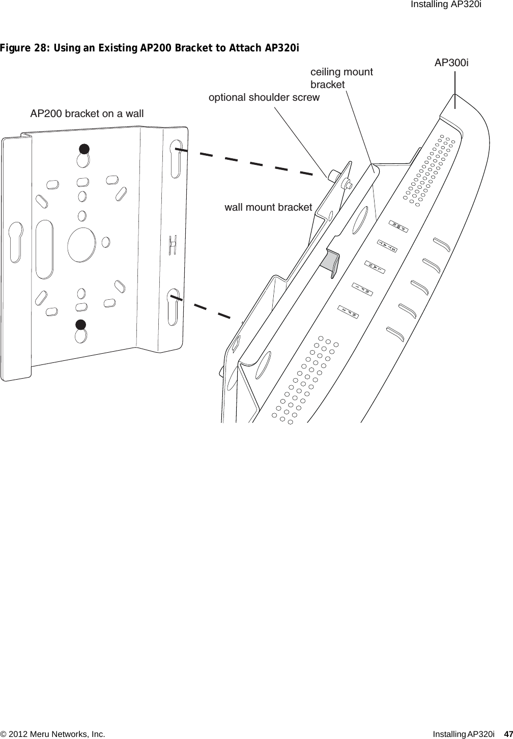
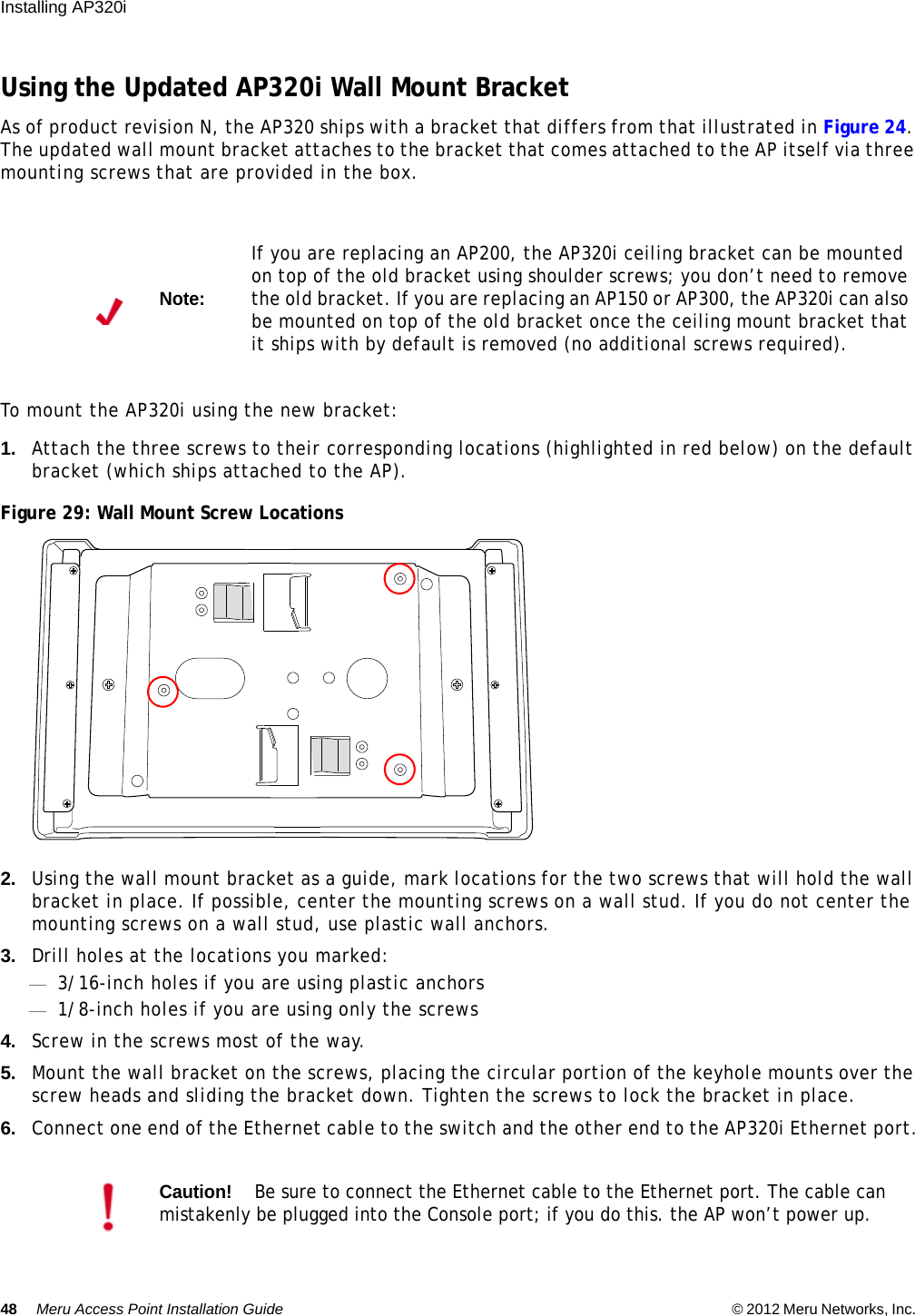
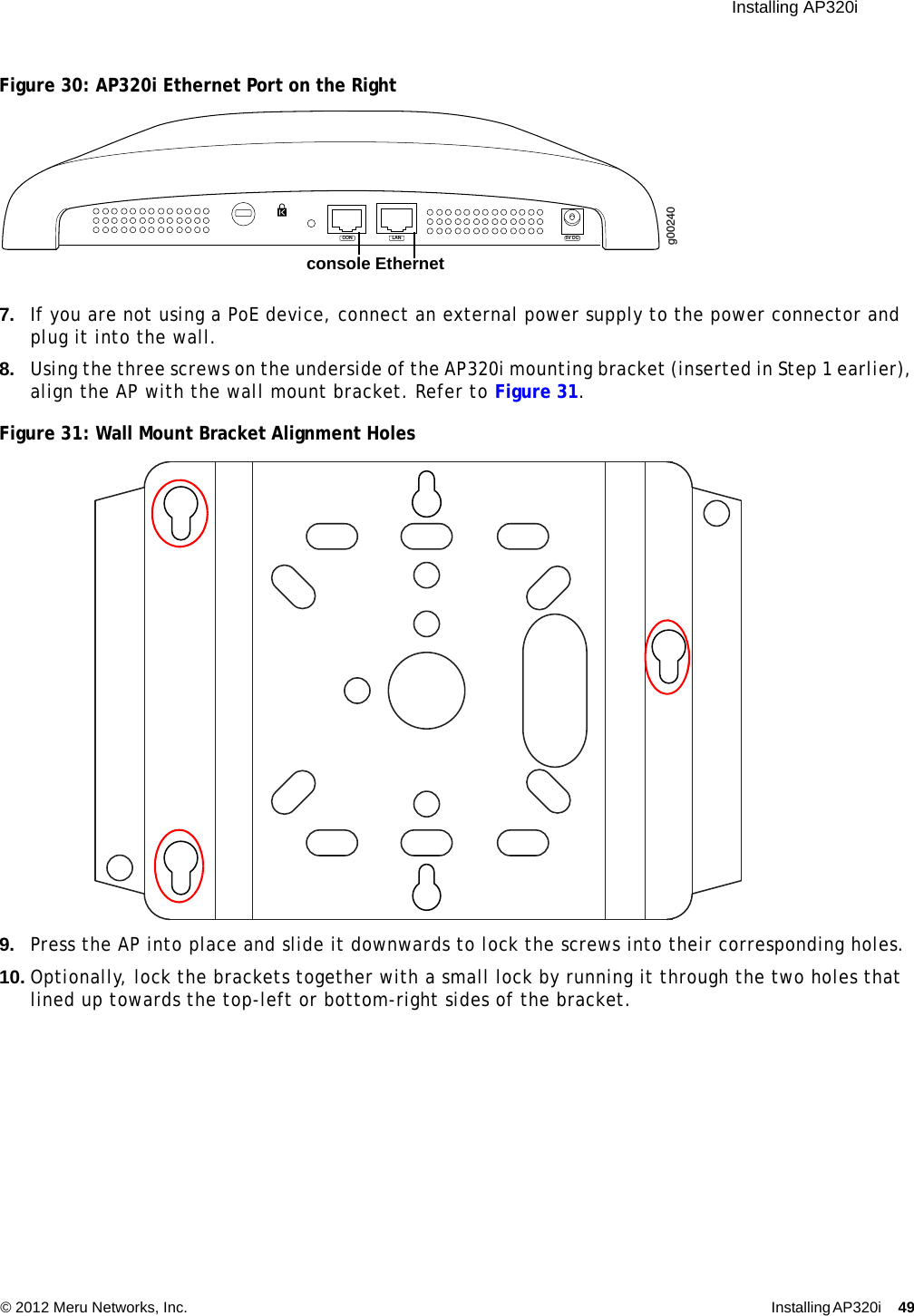
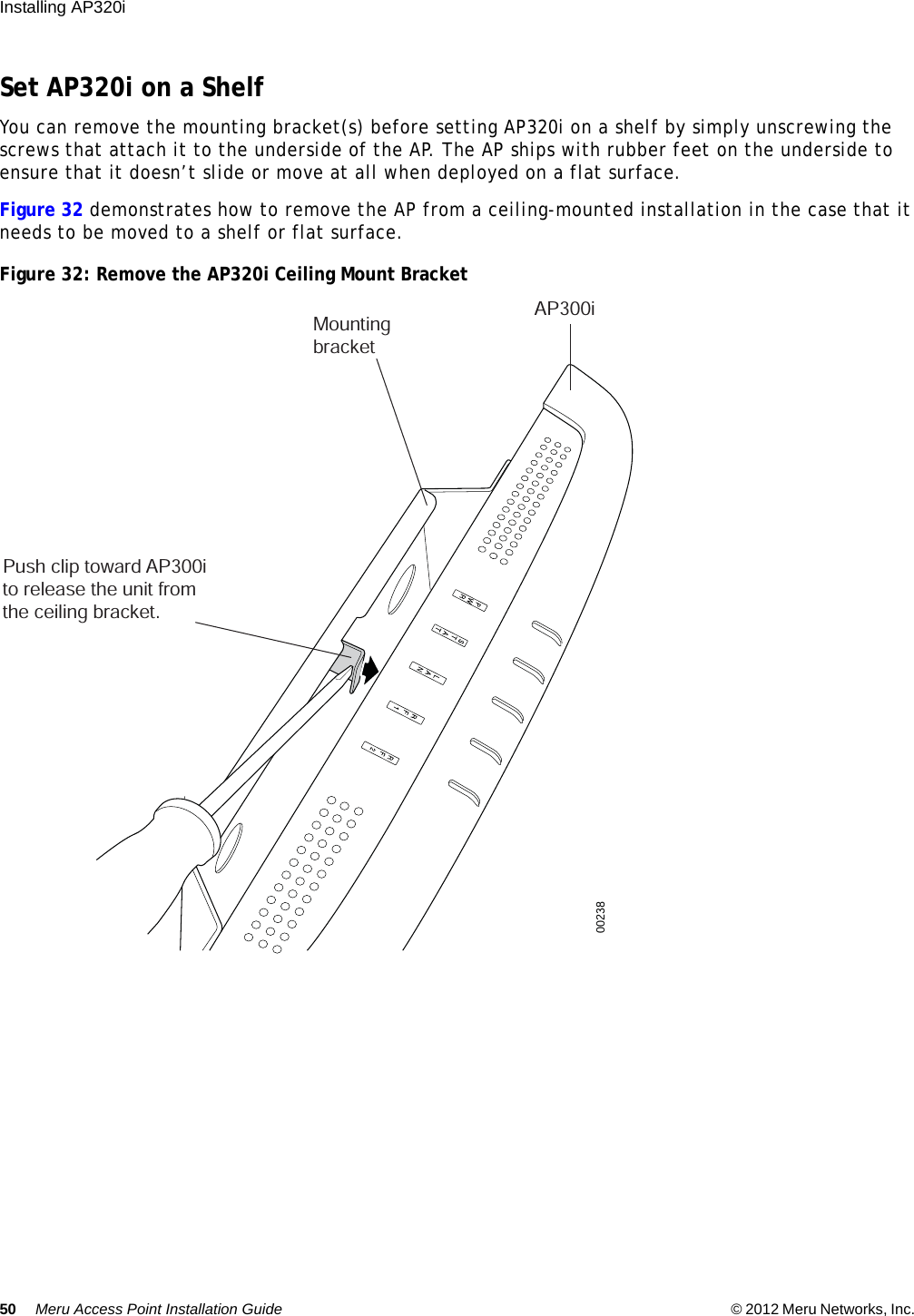
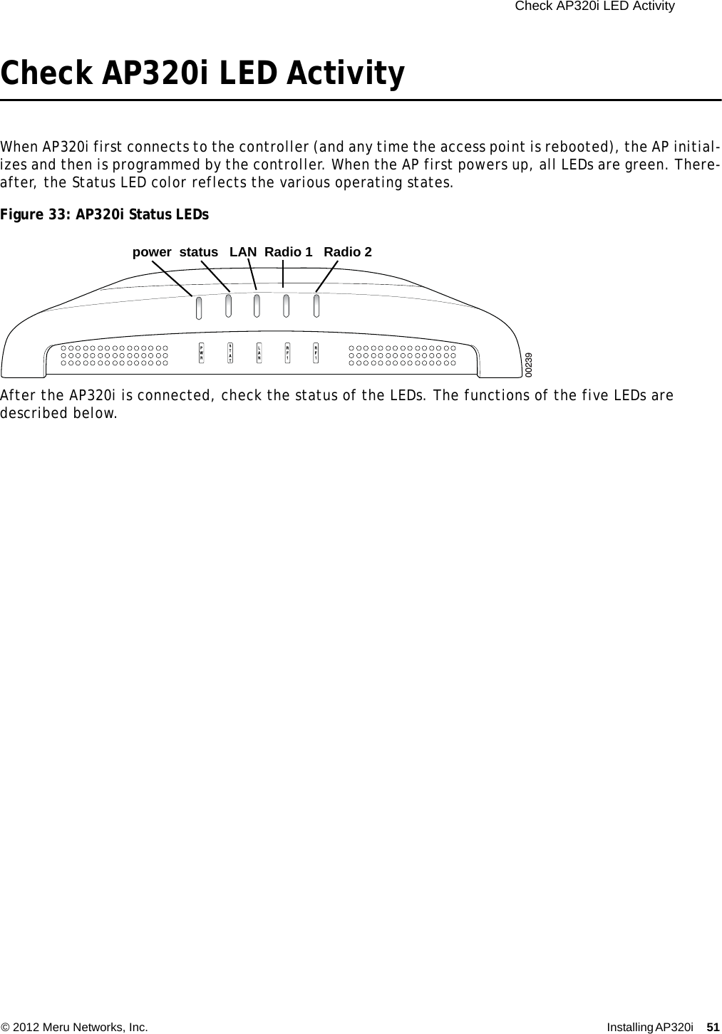
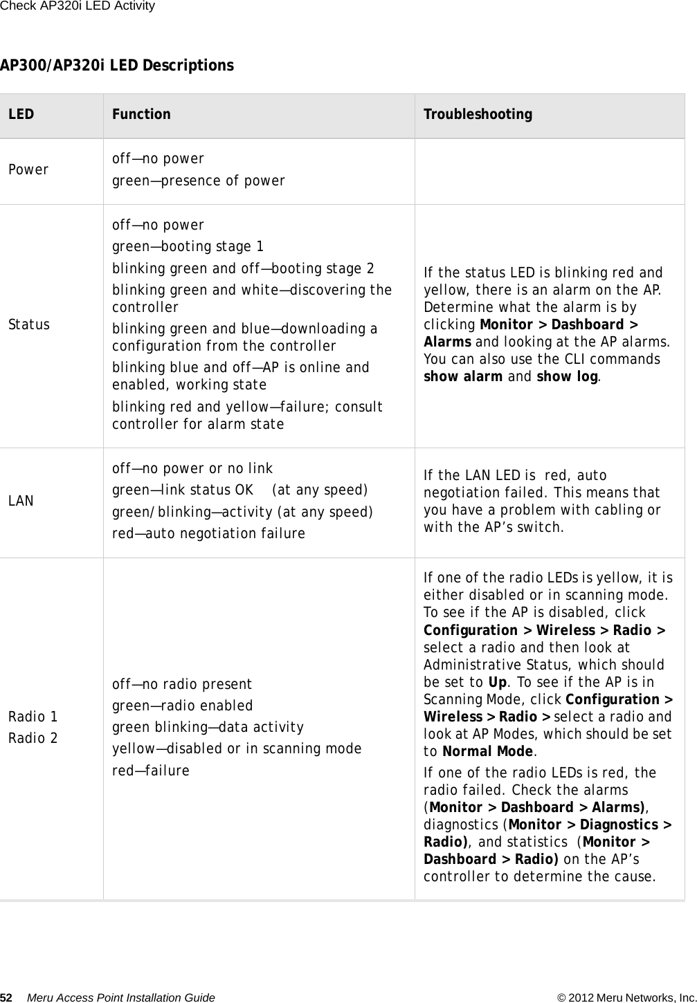
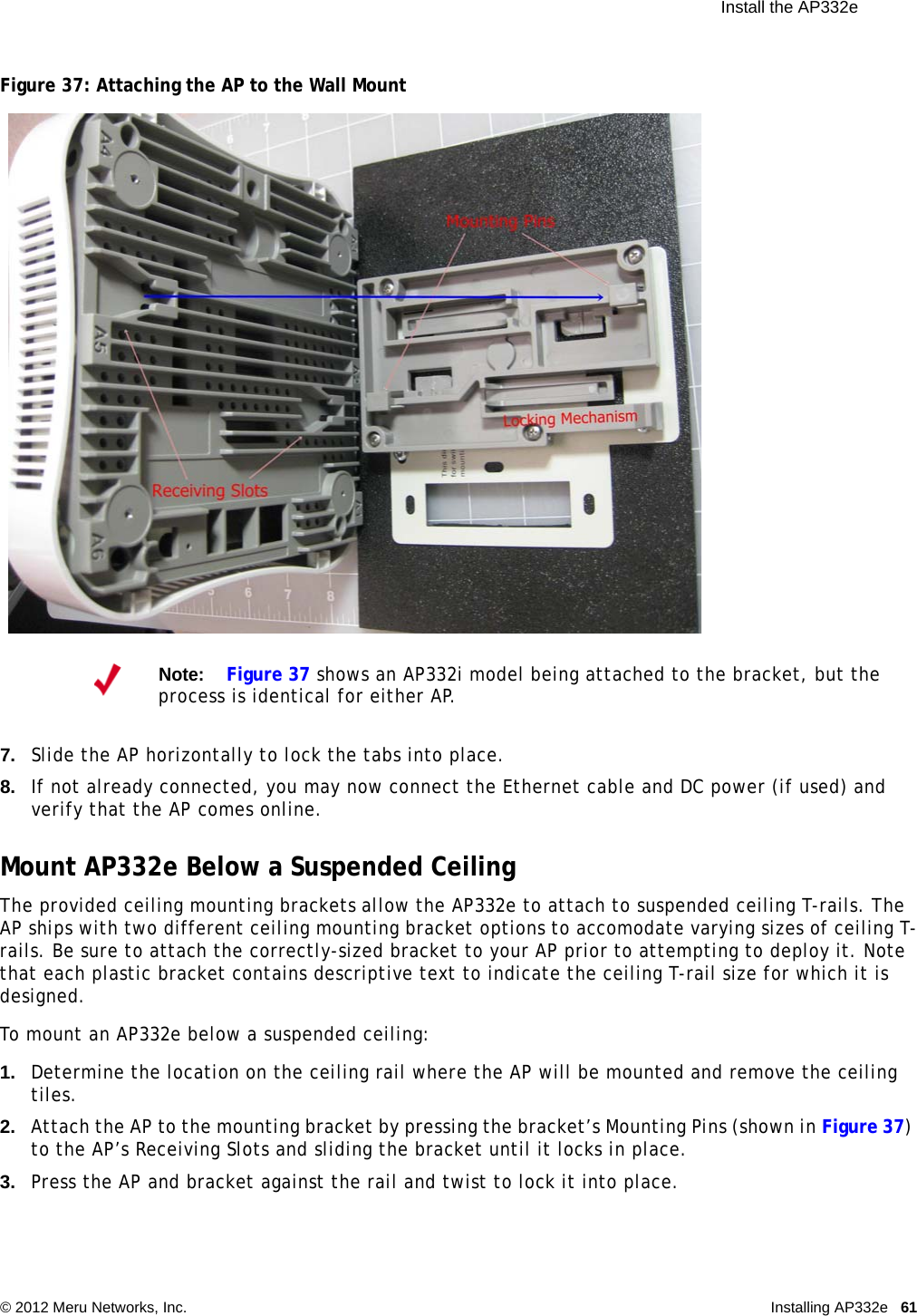
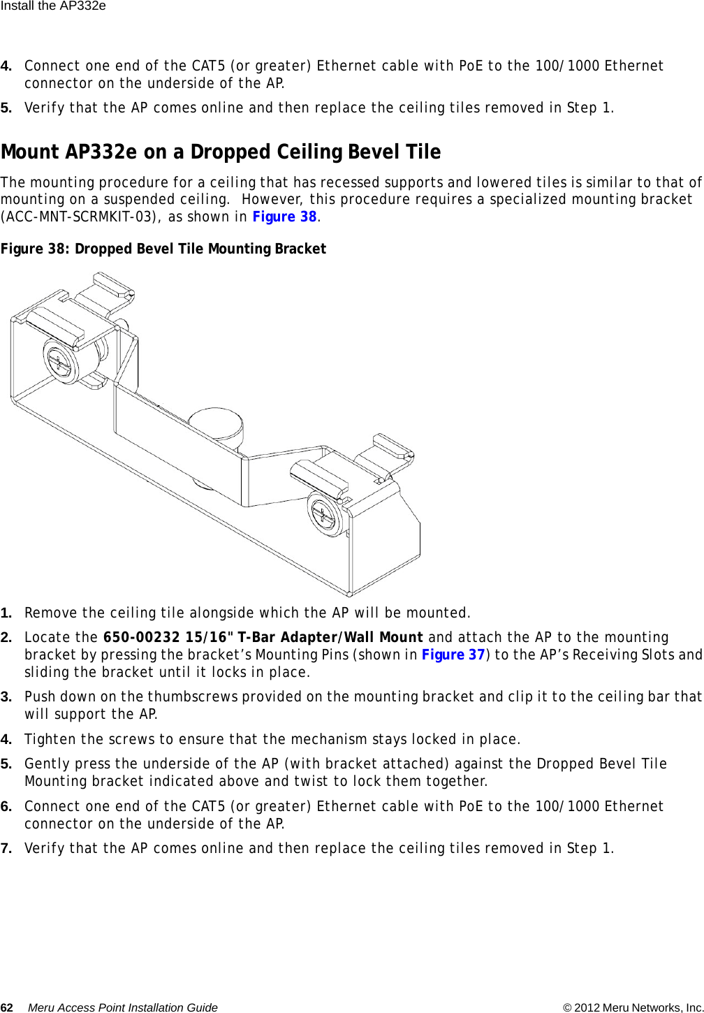
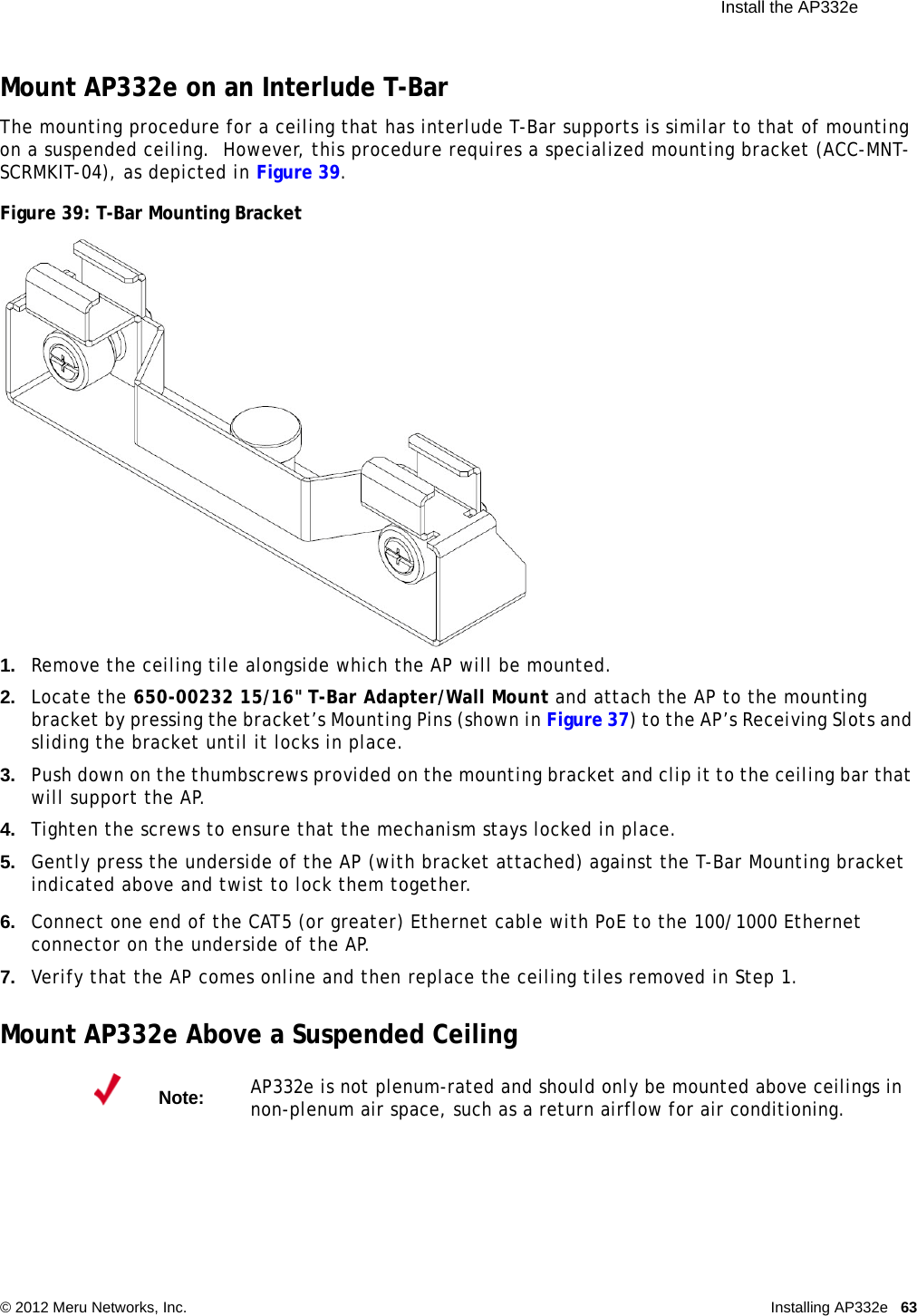
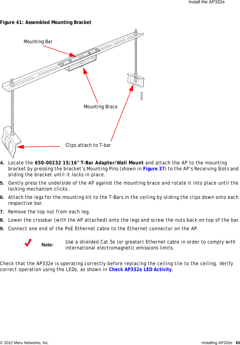
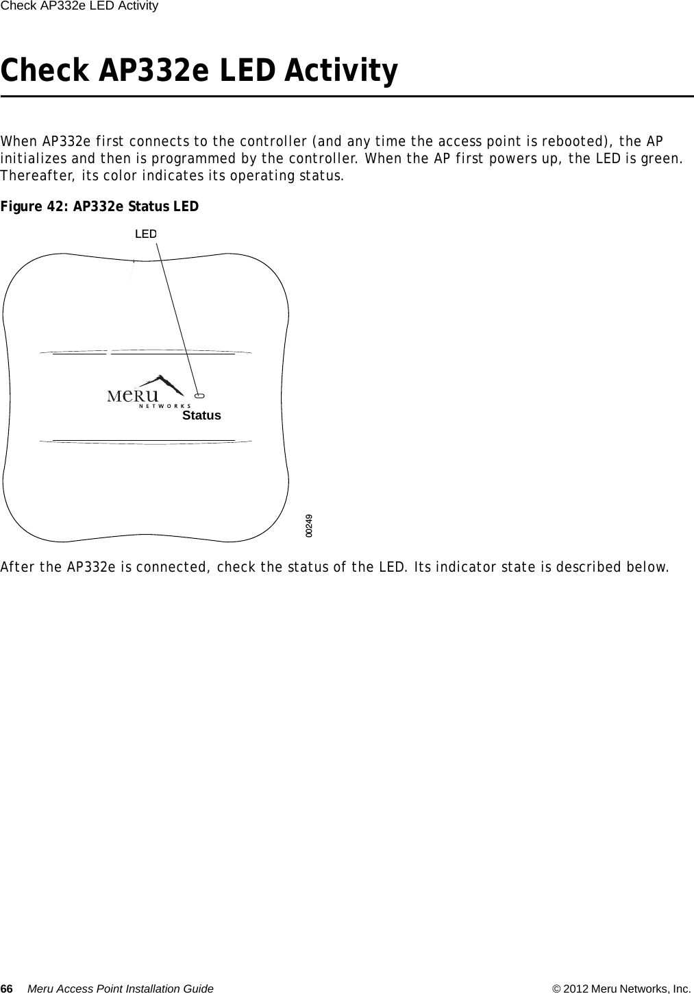
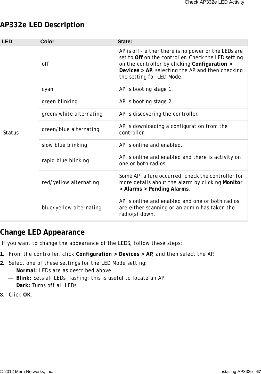
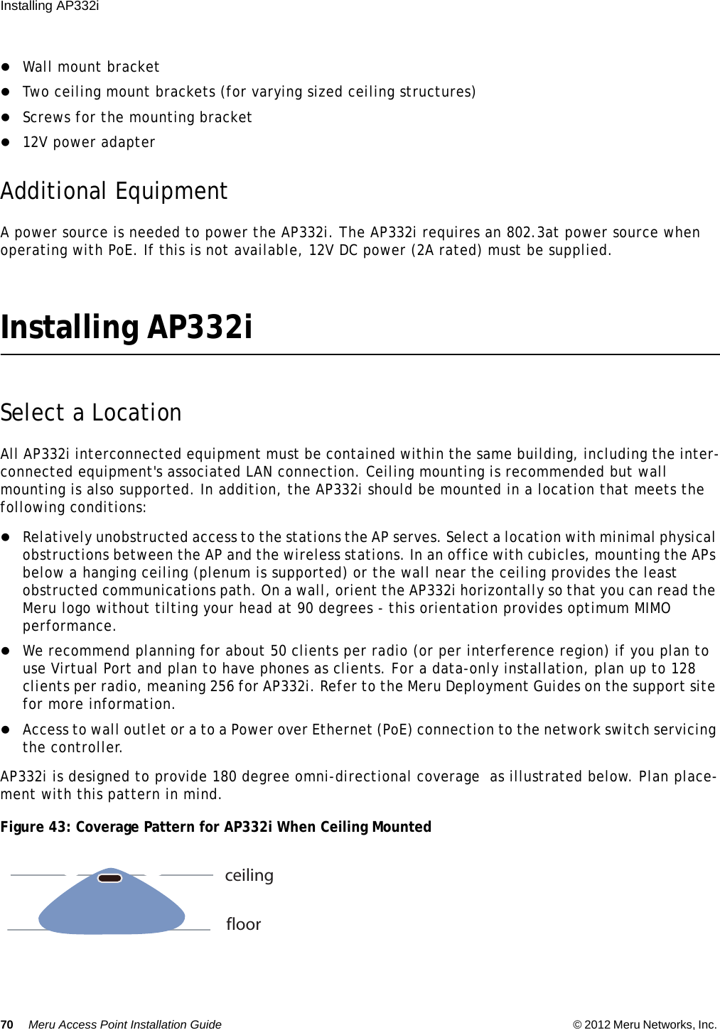
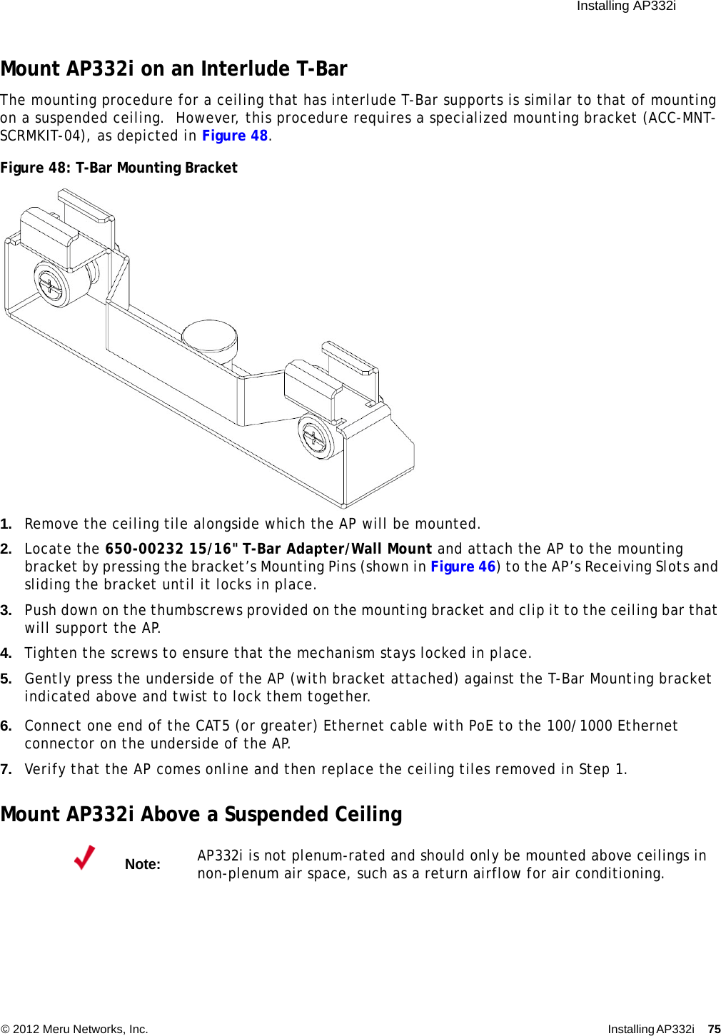
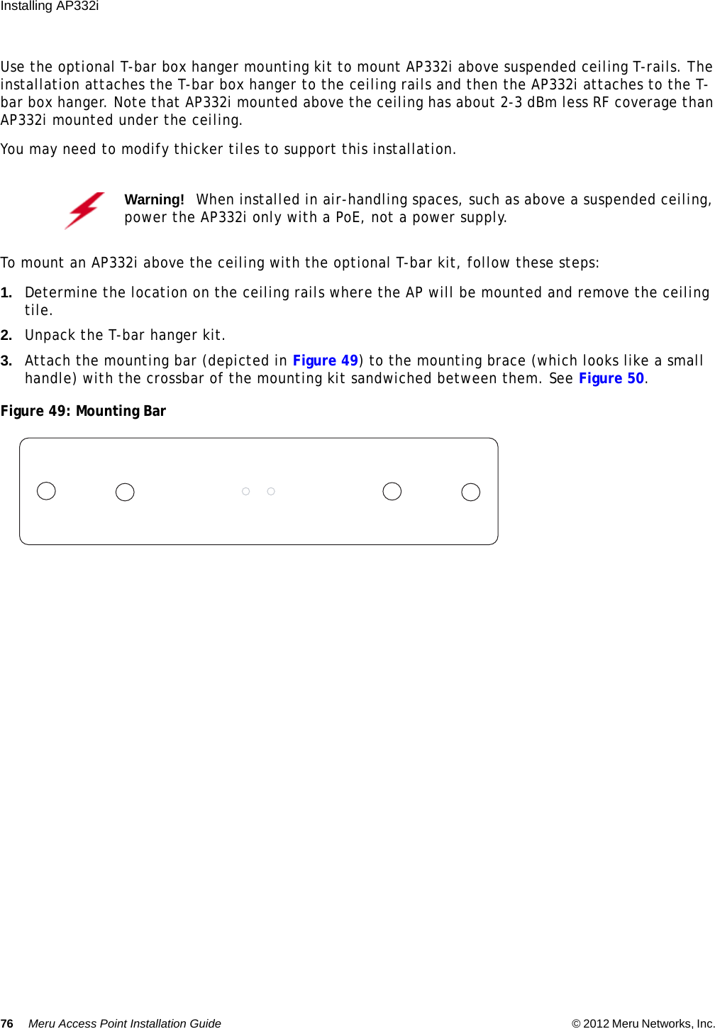
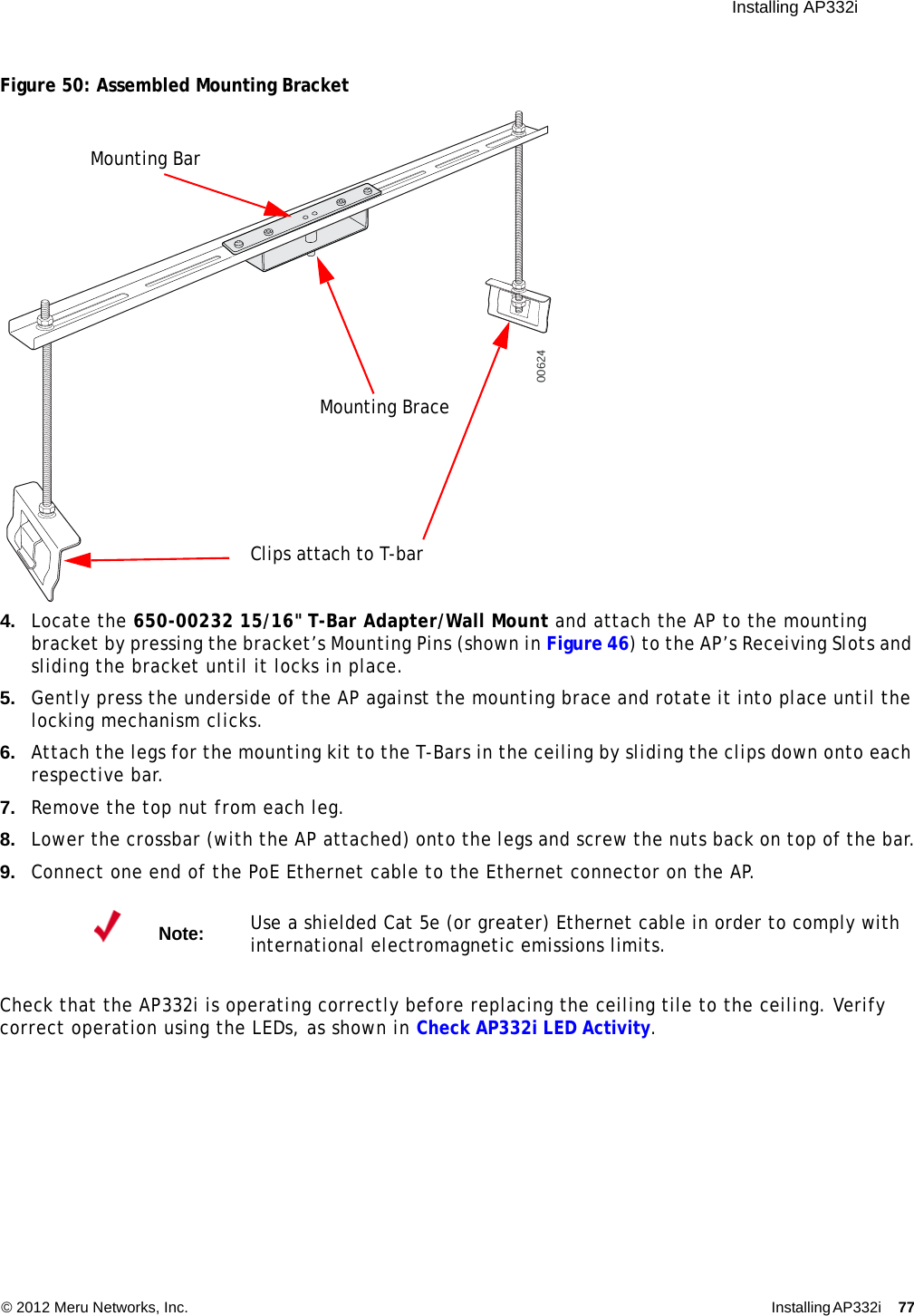
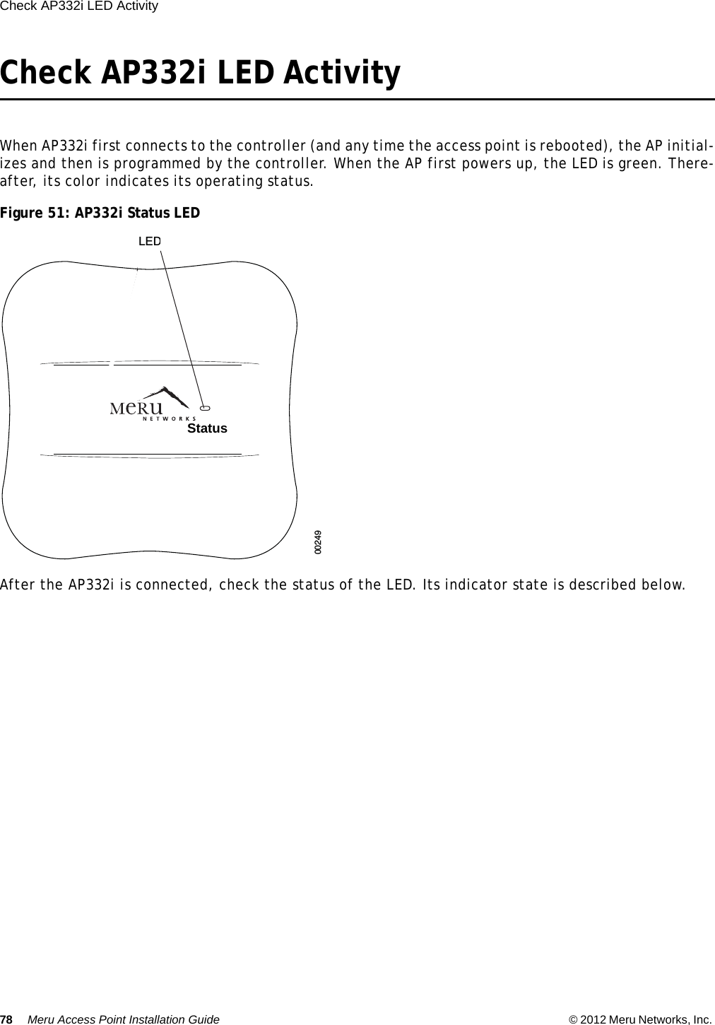
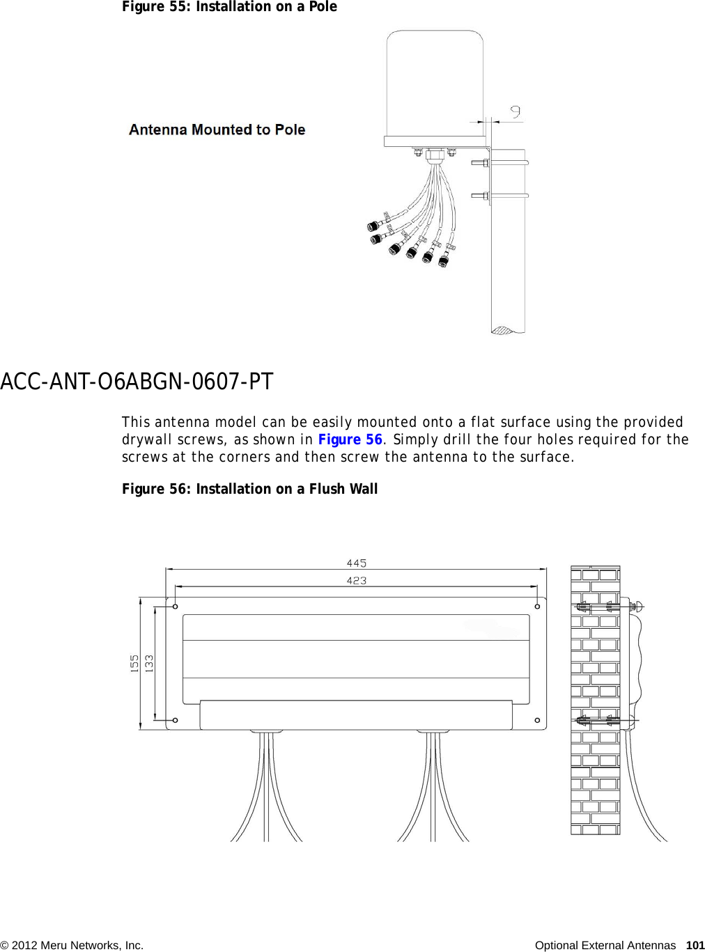
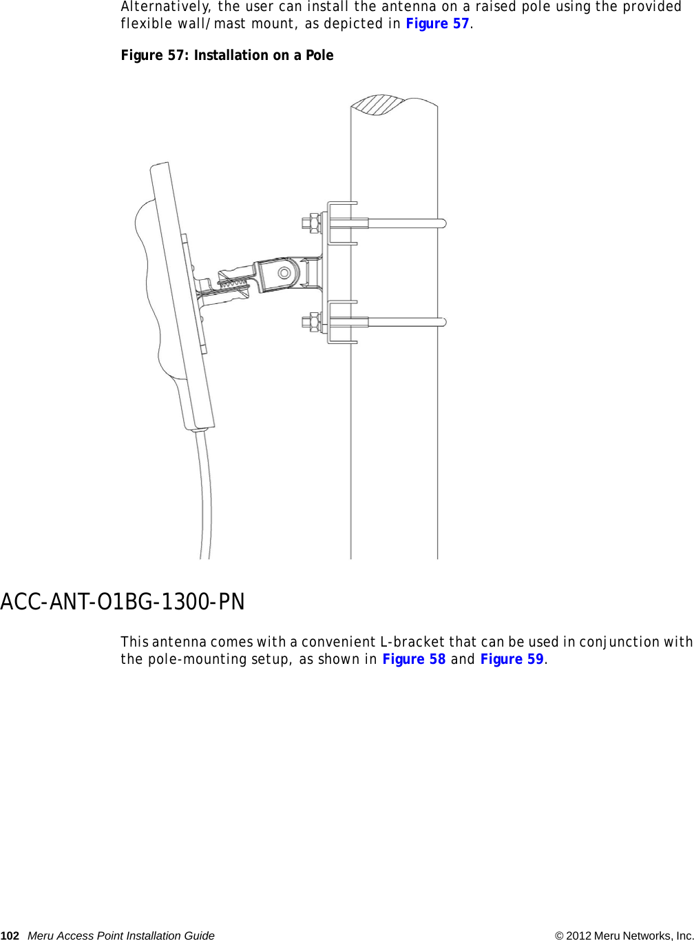
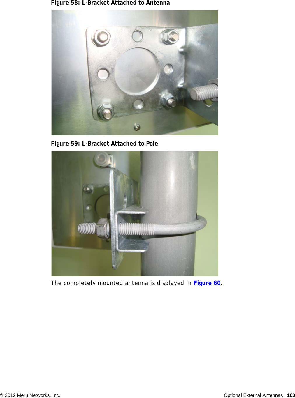
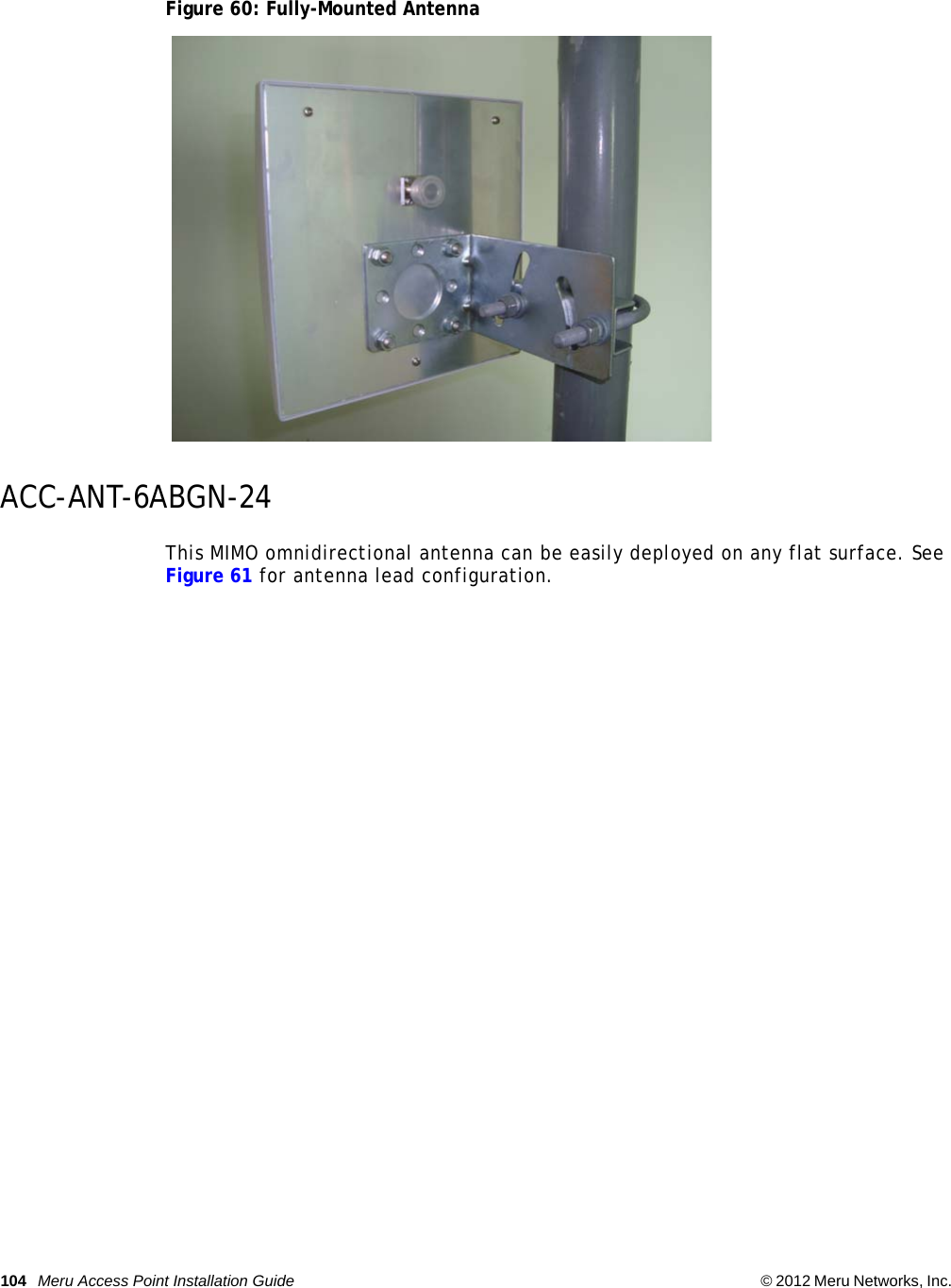
Installation Guide
Navigation menu
Upload a User Manual
Namespaces
Wiki Guide
HTML
PDF
Info
Views
User Manual
Discussion / Help
Navigation