Meru Networks AP433IS Triple Radio Access Point User Manual
Meru Networks Inc. Triple Radio Access Point
User Manual
Meru Networks AP433
Installation Guide
MERU NETWORKS, INC.
Limited Product Warranty
This Limited Product Warranty applies to the original end-user customer of the
Meru product which you purchased for your own use, and not for resale
(“Product”), from Meru Networks,
Inc. (“Meru”) or its authorized reseller
(“Reseller”).
Limited Warranties
One-year limited hardware warranty: Meru warrants to you that Meru hardware
(other than Third Party Products as described below) will be free from defects in
materials and work- manship for a one-year period after the date of delivery of
the applicable product to you from Meru or its Reseller (the “Hardware Warranty
Period”). If Meru receives written notice from you of such defects during the
Hardware Warranty Period, Meru will, at its option, either repair or replace Meru
hardware that Meru determines to be defective. Replacement products may be
remanufactured units, and will be warranted for the remainder of the origi- nal
Hardware Warranty Period, or if greater, for thirty days from delivery of such
replace- ment. Should Meru be unable to repair or replace the Meru hardware,
Meru (or its Reseller,
as applicable) will refund to you the purchase price of the
Product.
90-Day Limited Software Warranty: Meru warrants to you that, for a 90-day period
after the date of delivery of the applicable product to you from Meru or its
Reseller (the “Software Warranty Period”), when properly installed and used, (a)
the media on which the Meru soft- ware is provided will be free from defects in
materials or workmanship; and (b) the Meru software will substantially conform
to the functional specifications in the applicable docu- mentation. If Meru
receives written notice from you of a breach of this warranty during the Software
Warranty Period and is able to reproduce the defect, Meru will, at its option, either
repair or replace the defective Meru software. Should Meru be unable to repair or
replace the Meru software, Meru (or its Reseller, as applicable) will refund to you
the purchase price of the Product.
Exclusions
The warranty on the Product shall not apply to defects resulting from the following:
Alteration or modification of the Product in any way, including without limitation
configura- tion with software or components other than those supplied by Meru
or integration with parts other than those supplied by Meru.
Abuse, damage or otherwise being subjected to problems caused by negligence
or misap- plication (including without limitation improper or inadequate
maintenance or calibration),
relocation of the products (including without limitation
damage caused by use of other than Meru shipping containers), or use of the
products other than as specified in the applicable Meru product documentation
(including without limitation incompatible operating environ- ments and systems),
or improper site preparation or maintenance.
Damage as a result of accidents, extreme power surge, extreme electromagnetic
field, acts of nature or other causes beyond the control of Meru.
Use of the Product with software, interfacing, parts or supplies not supplied by
Meru.
The warranty on the Product does not apply if the Product is sold, or in the case
of software,
licensed, for free for evaluation or demonstration purposes.
Meru expressly disclaims any warranty or obligation to support the Product for
all operating environments – for example, as illustration and not limitation, Meru
does not warrant or ensure interoperability of the Product with future
telecommunication systems or other future software or hardware.
You understand and acknowledge that the Products may generate, use or
radiate radio fre- quency energy and may interfere with radio communications
and/or radio and television receptions if is not used and/or installed in
accordance with the documentation for such prod- ucts. WHILE MERU USES
COMMERCIALLY REASONABLE EFFORTS TO ENSURE COM- PLIANCE OF
THE PRODUCTS WITH APPLICABLE UNITED STATES FEDERAL
COMMUNICATIONS COMMISSION AND PROTECT AGAINST HARMFUL
INTERFER- ENCES, YOU ACKNOWLEDGE AND AGREE THAT
INTERFERENCES WITH RADIO COM- MUNICATIONS AND/OR RADIO AND
TELEVISION RECEPTIONS MAY OCCUR AND THAT
MERU WILL NOT BE
LIABLE FOR ANY DAMAGES OR INCONVENIENCE BASED ON SUCH
INTERFERENCES.
Third Party Products - The above Limited Warranties are exclusive of
products manufac- tured by third parties (“Third Party Products”). If such third
party manufacturer provides a sep- arate warranty with respect to the Third Party
Product, Meru will include such warranty in the packaging of the Meru Product.
Return procedures
To obtain warranty service you must: (a) obtain a return materials
authorization number (“RMA#”) from Meru by contacting
rmaadmin@merunetworks.com, and (b) deliver the Prod- uct, in accordance with
the instructions provided by Meru, along with proof of purchase in the form of a
copy of the bill of sale including the Product’s serial number, contact information,
RMA# and detailed description of the defect, in either its original package or
packaging provid- ing the Product with a degree of protection equivalent to that of
the original packaging, to Meru
at the address below. You agree to obtain adequate insurance to cover loss or
damage to the Product during shipment.
If you obtain an RMA# and return the defective Product as described above, Meru
will pay the cost of returning the Product to Meru. Otherwise, you agree to bear
such cost, and prior to
receipt by Meru, you assume risk of any loss or damage
to the Product. Meru is responsible for the cost of return shipment to you if the
Meru Product is defective.
Returned products which are found by Meru to be not defective, returned out-of-
warranty or otherwise ineligible for warranty service will be repaired or
replaced at Meru’s standard charges and shipped back to you at your expense.
At Meru’s sole option, Meru may perform repair service on the Product at your
facility, and you agree to provide Meru with all reasonable access to such facility
and the Product, as required by Meru. On-site repair service may be available and
is governed by the specific terms of your purchase.
All replaced parts, whether under warranty or not, are the property of Meru.
Warranty limitations
THE WARRANTIES SET FORTH ABOVE ARE EXCLUSIVE AND NO OTHER
WARRANTY,
WHETHER WRITTEN OR ORAL, IS EXPRESSED OR IMPLIED
BY MERU, TO THE MAXI-
MUM EXTENT PERMITTED BY LAW. THERE ARE
NO OTHER WARRANTIES RESPECT- ING THE PRODUCT AND
DOCUMENTATION AND SERVICES PROVIDED UNDER THIS
AGREEMENT,
INCLUDING WITHOUT LIMITATION ANY WARRANTY OF DESIGN, MER-
CHANTABILITY, FITNESS FOR A PARTICULAR PURPOSE (EVEN IF MERU
HAS BEEN INFORMED OF SUCH PURPOSE), TITLE OR AGAINST
INFRINGEMENT OF THIRD PARTY RIGHTS. IF ANY IMPLIED WARRANTY
CANNOT BE DISCLAIMED UNDER APPLI-
CABLE LAW, THEN SUCH
IMPLIED WARRANTY SHALL BE LIMITED IN DURATION TO
THE
HARDWARE AND SOFTWARE WARRANTY PERIODS DESCRIBED ABOVE.
NO AGENT OF MERU IS AUTHORIZED TO ALTER OR EXCEED THE
WARRANTY OBLI-
GATIONS OF MERU.
MERU SPECIFICALLY DOES NOT WARRANT THAT THE MERU
SOFTWARE WILL BE
ERROR FREE OR OPERATE WITHOUT INTERRUPTION.
THE REMEDIES IN THIS LIMITED PRODUCT WARRANTY ARE YOUR SOLE
AND EXCLU- SIVE REMEDIES, AND MERU’S SOLE AND EXCLUSIVE
LIABILITY, FOR BREACH OF THE HARDWARE OR SOFTWARE WARRANTY
SET FORTH ABOVE.
Limitations of Liability
You acknowledge and agree that the consideration which you paid to Meru does
not include any consideration by Meru of the risk of consequential, indirect or
incidental damages which may arise in connection with your use of, or inability to
use, the Product. THUS, MERU AND ITS RESELLER WILL NOT BE LIABLE FOR
ANY INDIRECT, INCIDENTAL, SPECIAL, PUNI- TIVE OR CONSEQUENTIAL
DAMAGES, INCLUDING WITHOUT LIMITATION LOST PROF-
ITS, LOST
BUSINESS, LOST DATA, LOSS OF USE, OR COST OF COVER INCURRED BY
YOU ARISING OUT OF OR RELATED TO YOUR PURCHASE OR USE OF, OR
INABILITY
TO USE, THIS PRODUCT OR THE SERVICES, UNDER ANY
THEORY OF LIABILITY,
WHETHER IN AN ACTION IN CONTRACT, STRICT
LIABILITY, TORT (INCLUDING NEGLI-
GENCE) OR OTHER LEGAL OR
EQUITABLE THEORY, EVEN IF MERU OR ITS RESELLER KNEW OR SHOULD
HAVE KNOWN OF THE POSSIBILITY OF SUCH DAMAGES. IN ANY EVENT,
THE CUMULATIVE LIABILITY OF MERU OR ITS RESELLER FOR ALL
CLAIMS WHATSOEVER RELATED TO THE PRODUCT OR THE SERVICE WILL
NOT EXCEED THE PRICE YOU PAID FOR THE PRODUCT OR SERVICES
GIVING RISE TO SUCH CLAIMS.
THE LIMITATIONS SET FORTH HEREIN ARE INTENDED TO LIMIT THE
LIABILITY OF
MERU AND ITS RESELLERS AND SHALL APPLY
NOTWITHSTANDING ANY FAILURE OF
ESSENTIAL PURPOSE OF ANY
LIMITED REMEDY.
The jurisdiction applicable to you may not allow the limitations of liability or
damages set forth
above, in which case such limitation shall only apply to you
to the extent permitted in such jurisdiction.
Additional Information
This Limited Product Warranty shall be governed by and construed in
accordance with the laws of the State of California, U.S.A., exclusive of its conflict
of laws principles. The U.N. Con- vention on Contracts for the International Sale of
Goods shall not apply.
This Limited Product Warranty is the entire and exclusive agreement between
you and Meru with respect to its subject matter, and any modification or waiver of
any provision of this state- ment is not effective unless expressly set forth in
writing by an authorized representative of
Meru.
All inquiries or claims made under this Limited Product Warranty must be sent to
Meru at the following address:
Meru Networks Inc.,
894 Ross Drive, CA 94087, USA
Tel: 408-215-5300
Fax: 408-215-5301
Email: support@merunetworks.com
Contents
1 About this Guide ..................................................................................................... 8
1.1 Audience........................................................................................................... 8
1.2 Other Sources of Information ........................................................................... 8
1.2.1 Meru Publications ..................................................................................... 8
1.2.2 Website Resources .................................................................................... 8
1.3 Typographic Conventions ................................................................................ 8
2 Contacting Meru ................................................................................................... 10
2.1 Customer Services and Support ..................................................................... 10
2.2 RMA Procedures ............................................................................................ 10
3 AP433 Series ......................................................................................................... 11
3.1 What is AP433? .............................................................................................. 11
3.2 AP433 Series Configurations ......................................................................... 11
3.3 Features for AP433 Series .............................................................................. 11
4 Installing AP433e.................................................................................................. 14
4.1 Safety Precautions .......................................................................................... 14
4.2 Package Content, AP433e .............................................................................. 14
4.3 Determine Power Requirements..................................................................... 14
4.3.1 IEEE Std 802.3af PoE Usage .................................................................. 14
4.3.2 IEEE Std 802.3at PoE Usage .................................................................. 14
4.4 Installation Requirements ............................................................................... 15
4.5 Additional Equipments ................................................................................... 15
4.6 Install the AP433e .......................................................................................... 15
4.6.1 Select a Location ..................................................................................... 15
4.6.2 Attach the Provided Antennas ................................................................ 16
4.6.3 AP433e Antenna Port-Radio Mapping ................................................... 17
4.7 Install the Access Point AP433e .................................................................... 18
4.7.1 Mount AP433e Horizontally on a Shelf .................................................. 18
4.7.2 Mount AP433e Vertically on a Wall ...................................................... 18
4.7.3 Mount AP433e below a Suspended Ceiling ........................................... 20
4.7.4 Mount AP433e above a Suspended Ceiling (Plenum) ............................ 21
4.7.5 Mount AP433e on a Dropped Ceiling Bevel Tile ................................... 23
4.7.6 Mount AP433e on an Interlude T-Bar .................................................... 24
4.8 Check AP433e LED Activity ......................................................................... 25
4.8.1 AP433e LED Description ....................................................................... 25
4.8.2 Change LED Appearance ....................................................................... 25
4.9 Approved Antennas for AP433e .................................................................... 26
4.10 Where to Go From Here ................................................................................. 26
5 Installing AP433i & 433is .................................................................................... 27
5.1 Note ................................................................................................................ 27
5.2 Safety Precautions .......................................................................................... 27
5.3 Package Content, AP433i & 433is ................................................................. 27
5.4 Determine Power Requirements..................................................................... 27
5.4.1 IEEE Std 802.3af PoE Usage .................................................................. 27
5.4.2 IEEE Std 802.3at PoE Usage .................................................................. 28
5.5 Installation Requirements ............................................................................... 28
5.6 Additional Equipments ................................................................................... 28
5.7 Install the AP433i & 433is ............................................................................. 28
5.7.1 Select a Location ..................................................................................... 28
5.8 Install the Access Point AP433i & 433is ....................................................... 29
5.8.1 Mount AP433i & 433is Horizontally on a Shelf .................................... 29
5.8.2 Mount AP433i & 433is Vertically on a Wall ......................................... 29
5.8.3 Mount AP433i & 433is below a Suspended Ceiling .............................. 33
5.9 Check AP433i & 433is LED Activity ............................................................ 34
5.9.1 AP433i & 433is LED Description .......................................................... 34
5.9.2 Change LED Appearance ....................................................................... 34
5.10 Where to Go From Here ................................................................................. 35
6 Installing OAP433e ............................................................................................... 36
6.1 Unpacking the OAP433e ................................................................................ 36
6.2 Installation Requirements ............................................................................... 36
6.3 Power Requirements ...................................................................................... 37
6.4 Assembling the Waterproof Ethernet Connector ........................................... 37
6.5 Installing the Access Point ............................................................................. 37
6.6 Radio Position Planning ................................................................................. 38
6.7 Radio Interference .......................................................................................... 38
6.8 Weather Conditions ........................................................................................ 38
6.9 Ethernet Cabling ............................................................................................. 39
6.10 Grounding....................................................................................................... 39
6.11 Test Basic Link Operation.............................................................................. 39
6.12 Mounting the Access Point ............................................................................ 40
6.12.1 Mounting OAP433e with the Pole-Mounting Bracket ........................... 40
6.12.2 Mounting OAP433e with the Wall-Mounting Bracket ........................... 41
6.12.3 Connecting Antennas and Ground Wire to OAP433e ............................ 43
6.13 Approved Antennas for OAP433e ................................................................. 45
6.14 Installation with ANT-O4ABGN-0606-O-N ................................................. 45
6.15 Installation with ANT-O4ABGN-0607-PT-N ............................................... 47
6.16 Installation with ANT-A08O-NM-1/2 & BG08O-NM .................................. 48
6.17 Where to Go From Here ................................................................................. 50
7 Regulatory Information ......................................................................................... 51
7.1 Regulatory Specifications ............................................................................... 51
7.2 Declaration of Conformity, Federal Communication Commission ............... 51
7.2.1 Manufacturer Information ....................................................................... 51
7.2.2 Declaration of Conformity ...................................................................... 51
7.3 Declaration of Conformity, Industry Canada ................................................. 52
7.3.1 Manufacturer Information ....................................................................... 52
7.3.2 Declaration of Conformity ...................................................................... 52
7.4 Declaration of Conformity, R&TTE Directive 1999/5/EC ............................ 53
7.4.1 Manufacturer Information ....................................................................... 53
7.4.2 Declaration of Conformity ...................................................................... 54
7.5 General Information of RF Exposure ............................................................. 55
7.5.1 International Guidelines .......................................................................... 55
7.5.2 FCC Guidelines ....................................................................................... 55
7.5.3 Industry Canada Guidelines .................................................................... 56
8 Remarks ................................................................................................................ 57
8.1 Maximum EIRP.............................................................................................. 57
8.2 Dual Concurrent Same Band Operation ......................................................... 57
8.3 Manufacturing Information ............................................................................. 57
8.4 Distributed Antenna Systems (DAS) .............................................................. 57
8.5 Air Handling Space Requirements .................................................................. 57
8.6 Frequencies Blocked for Regulatory Compliance ......................................... 58
8.7 Restriction of Hazardous Substances ............................................................. 58
8.7.1 European Community ............................................................................. 58
8.7.2 China ....................................................................................................... 58
8.8 Underwriters Laboratories .............................................................................. 58
9 Cautions and Warnings .......................................................................................... 59
9.1 Cautions .......................................................................................................... 59
9.2 Warnings ........................................................................................................ 60
1 About this Guide
This guide provides installation instructions for the Meru AP433 Series Access
Points. The term “access point” is used interchangeably throughout this document
to apply to any model when there are no differences among the models.
1.1 Audience
This guide is intended for anyone installing Meru Wireless LAN System Access
Points (APs).
1.2 Other Sources of Information
Additional information is available in the following Meru publications, Web site, and
external references.
1.2.1 Meru Publications
• Meru System Director Release Notes
• Meru System Director Getting Started Guide
• Meru Controller Installation Guide
• Meru System Director Command Reference
• Meru System Director Configuration Guide
1.2.2 Website Resources
For the first 90 days after you buy a Meru controller, you have access to online
support. If you have a support contract, you have access for the length of the
contract. See this web site for information such as:
• Meru System Director Release Notes
• Knowledge Base (Q&A)
• Customer Discussion Forum (URL: http://support.merunetworks.com)
• Meru System Director Getting Started Guide
• Meru Controller Installation Guide
• Meru System Director Configuration Guide
• Meru System Director Command Reference
External References
• Stevens, W. R. 1994. TCP/IP Illustrated, Volume 1, The Protocols.
Addison-Wesley, Reading, Mass.
• Gast, M.S. 2002. 802.11 Wireless Networks, the Definitive Guide.
O’Reilly and Associates, Sebastopol, Calif.
1.3 Typographic Conventions
This document uses the following typographic conventions to help you locate and
identify information:
Note
Provides extra information, tips, and hints regarding the topic.
Caution!
Identifies important information about actions that could result in damage to or loss
of data, or could cause the application to behave in unexpected ways.
Warning! I
Dentifies critical information about actions that could result in equipment failure or
bodily harm.
2 Contacting Meru
You can visit Meru Networks, Inc. on the Internet at this URL:
http://www.merunetworks.com
2.1 Customer Services and Support
For assistance, contact Meru Customer Services and Support 24 hours a day at
+1-888-637-8952 (+1-888-Meru-WLA(N)) or +1-408-215-5305. Email can be sent
to support@merunetworks.com.
Meru Networks, Inc. Customer Services and Support provide end users and
channel partners with the following:
• Telephone technical support
• Software update support
• Spare parts and repair service
2.2 RMA Procedures
Contact Meru Customer Services and Support for a Return Material Authorization
(RMA) for any Meru equipment.
• Please have the following available when making a call:
• Company and contact information
• Equipment model and serial numbers
• Meru software release and revision numbers (for example, SD 6.1)
• A description of the symptoms the problem is manifesting
• Network configuration
3 AP433 Series
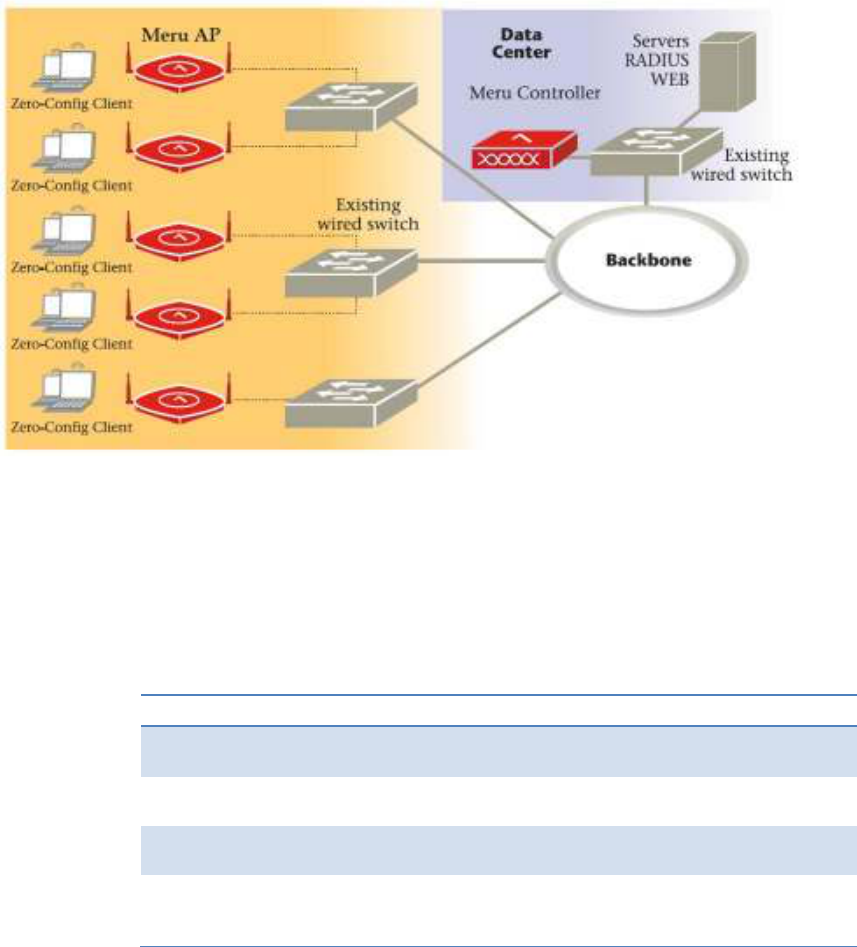
3.1 What is AP433?
Access Points contain radio devices that communicate with the Meru Controller
and form the wireless LAN (WLAN). The Meru Controller and Access Points
connect to the site’s wired LAN through wired switches. Wireless clients associate
with the Access Points as they roam throughout the WLAN. As such, they are an
extension of the wired LAN, providing the wireless benefits of client mobility,
enhanced access, and dynamic network configuration.
Figure 1 Wireless LAN Connected to a Network
The AP433 Series Access Point series delivers high performance, full-speed, Wi-
Fi certified 802.11n connectivity while simultaneously supporting legacy
802.11a/b/g devices. It is particularly suited to deployments that make use of voice
or video wireless applications.
The AP433 Series AP are available in the configurations shown below.
3.2 AP433 Series Configurations
Table 1, AP433 Series Configuration Table
Model Configuration
AP433e Three dual-band IEEE Std 802.11n radios with 3x3:3SS MIMO
and external antennas
AP433i Three dual-band IEEE Std 802.11n radios with 3x3:3SS MIMO
and internal antennas
AP433is Two dual-band IEEE Std 802.11n radios with 3x3:3SS MIMO and
a spectrum radio with internal antennas
OAP433e Three dual-band IEEE Std 802.11n radios (two with 3x3:3SS
MIMO, one with 2x2:2SS MIMO) and external antennas
(purchased separately)
3.3 Features for AP433 Series
Features for the AP433 Series include
• Up to three IEEE Std 802.11n-capable wireless radios with no licensing
requirement
• IEEE Std 802.11n support with channel bonding in both 2.4GHz and 5
GHz frequency bands’ channel bonding combines two 20MHz channels
into a single-wide 40MHz channel for increased throughput
• Plug and Play deployment using centralized controller platforms.
• Multi-layered security including standard WPA2, IEEE Std 802.11i
security (such as automatic traffic inspection)
• Each of these Access points may be powered by a standard IEEE Std
802.3af or IEEE Std 802.3at PoE device. However, in order to utilize all
three radios in 3x3:3SS operation, IEEE Std 802.3at-complied PoE
sources are required
• Air Traffic Control technology for IEEE Std 802.11n devices and legacy
a/b/g devices
• 3x3 MIMO with 3 transmits and 3 receive. Delivering three spatial
streams
• Channel span architecture which requires no channel planning or
configuration
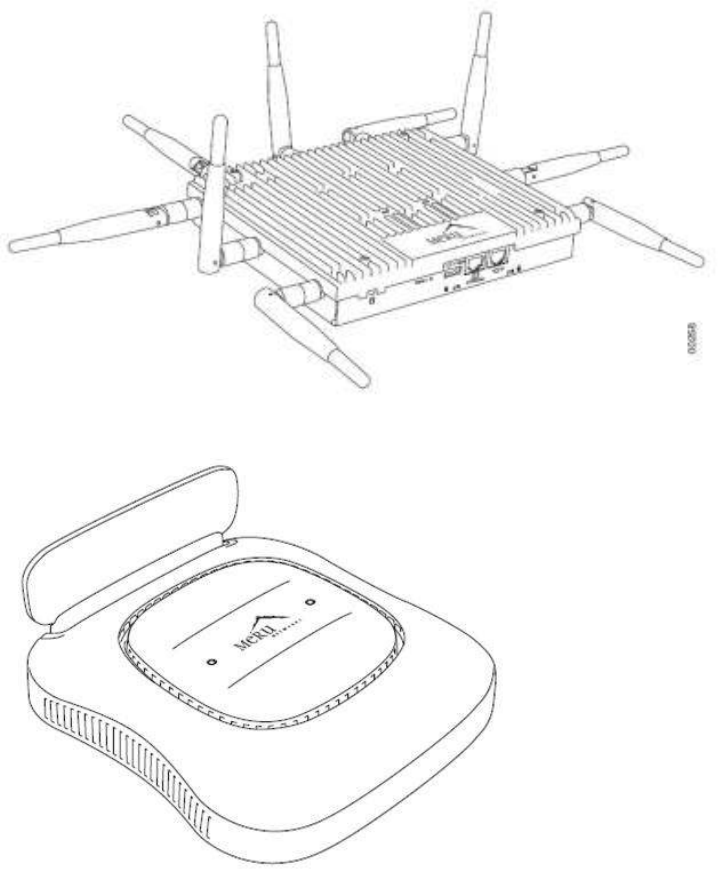
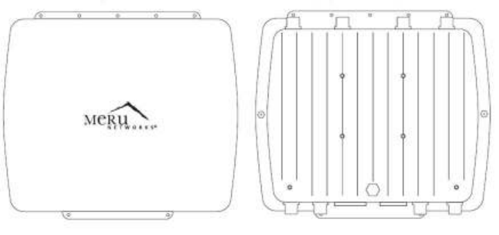
Figure 2 AP433e
Figure 3 AP433i & AP433is
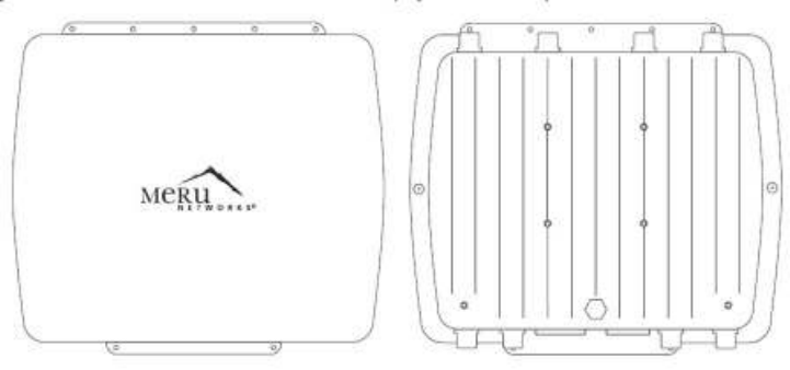
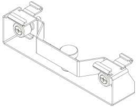
Figure 4, OAP433e Outdoor AP

4 Installing AP433e
This chapter describes how to install and configure an AP433e, which is supported
on System Director Version 6.0-SR1 and later. It contains the following sections,
• Safety Precautions
• Unpack the AP433e
• Determine Power Requirements
• Installation Requirements
• Install the AP433e
• Check AP433e LED Activity
• Where to Go From Here
4.1 Safety Precautions
IMPORTANT—Read and follow the regulatory instructions in Appendix B before
installing and operating this Product.
The AP433e is intended only for installation in Environment A as defined in IEEE
Std 802.3af and 802.3at. All interconnected equipments must be contained within
the same building, including the interconnected equipment's associated LAN
connection.
4.2 Package Content, AP433e
Confirm that the AP433e shipping package contains these items:
• AP433e
• Nine (9) external antennas
• Wall mounting bracket
• Rubber feet
• Locking pin
• Two mounting screws
4.3 Determine Power Requirements
Power requirements vary, depending on which AP433e radios are deployed and
what MIMO mode is used. See the chart below for supported power sources for
different radio configurations.
Table 2, Power Source & Radio Supported in AP433
Power Source Radio Supported
IEEE Std 802.3af Radio 1 and Radio 2
IEEE Std 802.3at Radio 1, 2, and 3
4.3.1 IEEE Std 802.3af PoE Usage
When using System Director V6.0 SR2 (or earlier Version) and an IEEE Std
802.3af PoE power source, Meru only supports two radios (radio 0 and 1).
This is because three radios using an IEEE Std 802.3af switch/PoE injector may
not have enough power to operate properly. When using an 802.af PoE, Meru
supports single or dual radios utilizing up to 3 antennas each.
4.3.2 IEEE Std 802.3at PoE Usage

When using System Director V6.0 SR2 (or earlier version) and an IEEE Std
802.3at, all possible configurations are supported (all three radios utilizing up to 3
antennas each). or a list of supported PoEs, see the appendix Supported Power
Over Ethernet Devices for Meru APs.
4.4 Installation Requirements
An array of holes on the mounting bracket allows the AP433e to be mounted on
the wall and over junction boxes or molly bolts. There are holes for passing the
PoE Ethernet or external power supply cable through the bracket if the bracket is
mounted on a junction box.
The AP433e has a security cable slot so you can lock the AP433e with a standard
security cable, such as those used to secure laptop computers.
Purchase optional mounting kits to mount the AP433e either from the ceiling or
inside an enclosure:
Above Suspended Ceiling Mounting Kit (T-Bar Hanger): MNT-SCRMKIT-01
Above hanging ceiling tiles. Suitable for use in environmental air space in
accordance with the Section 300-22(c) of the National Electric Code and Sections
2- 128.12 - 010 (3) and 12 - 100 of the Canadian Electrical Code. Part 1. C22. 1.
To complete AP433e installation, you need the items listed below.
Table 3, AP433e Installation Requirements
Installation Type Item Required
Horizontal mounting None
Vertical mounting over a wall stud Four #6 x 2" wood screws for a wood
stud; or
Four #6 x 1½” metal screws for a metal
stud
Mounting bracket
Vertical mounting on sheetrock Four #6 x 1" screws
Four #4-6 x 7/8” ribbed plastic wall
anchors
Mounting bracket
Horizontal mounting below a hanging
ceiling None
Mounting above a ceiling tile Mounting bracket MNT-SCRMKIT
4.5 Additional Equipments
A power source is needed to power the AP433e. See Determine Power
Requirements.
4.6 Install the AP433e
This section describes how to install an AP433e, which is supported on System
Director Version 6.0-SR1 and later. It contains the following subjects,
• Select a Location
• Attach the Provided Antennas
• Install the Access Point
4.6.1 Select a Location
All AP433e interconnected equipment, including the associated LAN connection,
must be contained within the same building. In addition, the AP433e location
should meet the following conditions:
Relatively unobstructed access to the stations the AP serves. Select a location
with minimal physical obstructions between the AP and the wireless stations. In an
office with cubicles, mounting the APs below a hanging ceiling (plenum is
supported) or the wall near the ceiling provides the least obstructed
communications path. On a wall, orient the AP433e horizontally so that you can
read the Meru logo without tilting your head at 90 degrees - this orientation
provides optimum MIMO performance.
Meru recommends planning for about 50 clients per radio (or per interference
region) if you plan to use Virtual Port and plan to have phones as clients. For a
data-only installation, plan up to 128 clients per radio. Refer to the Meru
Deployment Guides on the support site for more information.
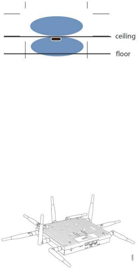
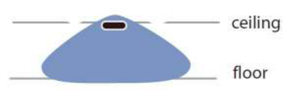
AP433e is designed to provide 360 degree omni-directional coverage as illustrated
below. Plan placement with this pattern in mind.
Figure 5, Coverage Pattern for AP433e when Ceiling Mounted
Most installations receive the best coverage using the following guidelines:
Install APs toward the center of the building.
Place APs about 80 feet apart.
Do not install APs near metal objects, such as heating ducts, metal doors, or
electric service panels.
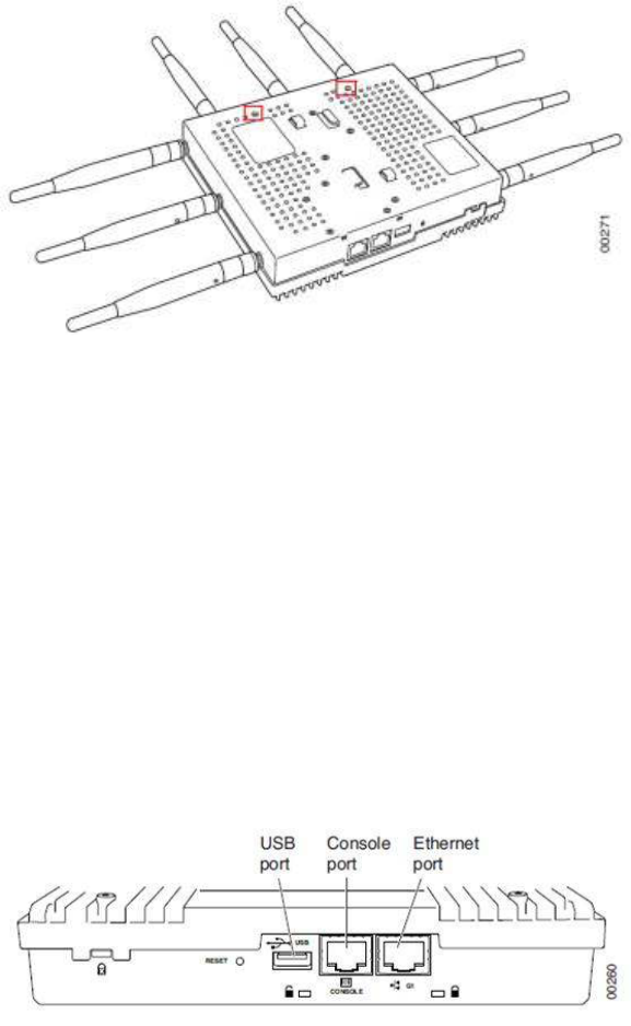
For best coverage, orient antennas as shown in Figure 2 AP433e.
4.6.2 Attach the Provided Antennas
All AP433es have nine external antenna ports, labeled A1 – A9. These units
operate with nine antennas attached, even though some configurations don’t use
all nine. Instead of attaching an antenna, you can cap unused antenna connectors
with 50 ohm Reverse Polarity SMA terminators. (For a list of approved terminators,
see http://support.merunetworks.com/.) Meru-supplied antennas are suitable only
for indoor use. To achieve the best performance from your AP433e, user shall
position antennas at a 90 degree angles relative to each other as shown in Figure
6, AP433e Antennas in Ceiling and Wall-mount Configuration. (The antennas do
not have to be oriented exactly as shown in the figure, but it is important to
maintain the relative angles.) If for some reason you are unable to maintain those
angles, the network will still operate, but you may experience up to a 20% drop in
throughput depending on the antenna orientation.
Figure 6, AP433e Antennas in Ceiling and Wall-mount Configuration
Do not leave any antenna connectors opened. All connectors on the AP must be

terminated with antennas or with 50 ohm Reverse Polarity SMA terminators.
The attached antennas must be the same model; if you replace one antenna with
a different type, replace them all.
4.6.3 AP433e Antenna Port-Radio Mapping
Table 4AP433e Antenna Port-Radio Mapping
Antenna Port Radio (Stream ID)
A1 Radio 1 (first stream)
A2 Radio 1 (second stream)
A3 Radio 1 (third stream)
A4 Radio 2 (first stream)
A5 Radio 2 (second stream)
A6 Radio 2 (third stream)
A7 Radio 3 (first stream)
A8 Radio 3 (second stream)
A9 Radio 331 (third stream)
4.7 Install the Access Point AP433e
AP433e ships with a mounting bracket included in the box. This bracket is
intended for installation as a wall-mount; for mounting on a ceiling, no mount is
typically required. See the following subjects for more specific details.
• Mount AP433e Horizontally on a Shelf
• Mount AP433e Vertically on a Wall
• Mount AP433e Below a Suspended Ceiling
• Mount AP433e Above a Suspended Ceiling (Plenum)
4.7.1 Mount AP433e Horizontally on a Shelf
When mounting an AP433e horizontally, no mounting bracket is required. Be sure
to position the antennas vertically when an AP433e sits on a surface. In order to
ensure that the AP433e does not shift much, attach the rubber feet provided in the
box to the bottom of the AP.
Caution!
Be sure to connect the Ethernet cable to the Ethernet port; the cable can
mistakenly be plugged into the Console port. If you do this, the AP won’t power up.
4.7.2 Mount AP433e Vertically on a Wall
To mount an AP433e on a wall, use the provided mounting bracket, as shown in
Figure 7, AP433e Wall Mounting Bracket
Figure 7, AP433e Wall Mounting Bracket
• Place the mounting bracket against the wall with the sliding lock
mechanism facing upwards. The Quick Reference Installation instructions
on the bracket should be visible.
• Using the holes on the mounting bracket itself as a guide, mark the
location on the wall for the AP bracket mounting screws. If possible,
center the mounting screws on a wall stud. (If mounting on a wall stud is
impossible, use plastic wall anchors on the remaining screws.)
• Drill holes at the locations you marked:
• 3/16-inch holes if you are using plastic anchors
• 1/8-inch holes if you are using only the screws
• If you are using plastic anchors, install them in the holes.
• Line the bracket up with the holes and screw in the screws.
• Attach the mounting screws to the underside of the AP433e in the holes
provided (indicated in Figure 8, AP433e Mounting Screw Holes
Figure 8, AP433e Mounting Screw Holes
• Orient the AP433e horizontally so that you can read the Meru logo and
the Console and network ports are pointed downwards - this orientation
provides optimum MIMO performance.
• Align the mounting screws on the back of the AP433e with the
corresponding holes on the mounting bracket.
• Slide the AP433e downwards until the screws click into the holes. They
should seat fairly firmly.
• Slide the mounting bracket’s locking bar to the right, locking the AP in
place.
• If desired, use the provided clip to lock the bracket shut by sliding it
through the aligned holes on the right-hand side of the bracket.
• Attach the antennas to the AP.
• Connect one end of the Ethernet cable to the switch and the other end to
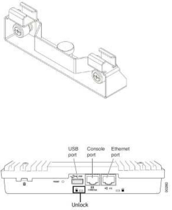
the AP433e Ethernet port. See Figure 9, IO Port of AP433e
Figure 9, IO Port of AP433e
Caution!
Be sure to connect the Ethernet cable to the Ethernet port; the cable can
mistakenly be plugged into the Console port. If you do this, the AP won’t power up.
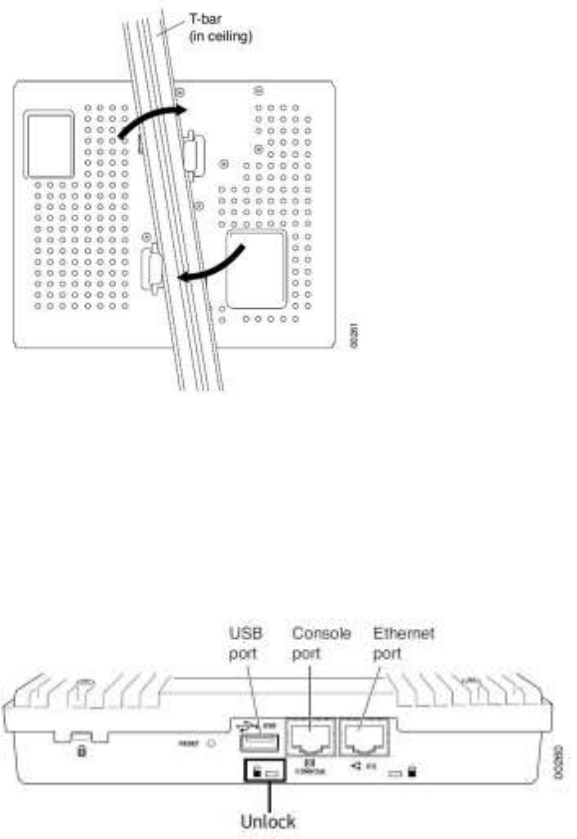
4.7.3 Mount AP433e below a Suspended Ceiling
The brackets on the bottom of the AP433e allow it to be mounted directly to a
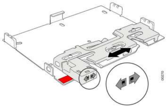
ceiling T-bar (see Figure 10). Note that the AP lock must be disabled by sliding the
locking key (provided in the box) into the unlock hole on the side of the AP shown
in Figure 9 in order to clip the AP in place (Figure 10: Mounting AP433e to a
Suspended Ceiling Rail)
Figure 10, Mounting AP433e to a Suspended Ceiling Rail
To mount an AP433e below a suspended ceiling:
• Determine the location on the ceiling rail where the AP will be mounted
and remove the ceiling tiles.
• Verify that the AP is unlocked using the locking key on the unlock
mechanism (on the same side as the Ethernet ports). See Figure 11,
Unlock
Figure 11, Unlock
• Press the AP433e against the T-bar at a slight angle and then rotate into
place, as indicated in Figure 10. You should hear it snap in place.
• For each antenna, loosen the knurled ring at the base of the antenna,
orient the antenna and then retighten the ring.
• Connect one end of the Ethernet cable to the switch and the other end to
the AP433e Ethernet port. See Figure 9, IO Port of AP433e
Caution!
Be sure to connect the Ethernet cable to the Ethernet port; the cable can
mistakenly be plugged into the Console port. If you do this. the AP won’t power up.
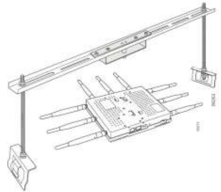
4.7.4 Mount AP433e above a Suspended Ceiling (Plenum)
Use the optional T-bar box hanger mounting kit to mount the AP433e above
suspended ceiling T-rails (Figure 12, AP433e Mounted above a Suspended
Ceiling Face Down). The installation attaches the T-bar box hanger to the ceiling
rails and then the AP433e attaches to the T-bar box hanger. Note that an AP433e
mounted above the ceiling has about 2-3 dBm less RF coverage than an AP433e
mounted under the ceiling.
The AP433e with the metal enclosure exposed meets the requirements for fire
resistance and low smoke-generating characteristics required by Section 300-
22(C) of the National Electrical Code (NEC) for installation in a building’s
environmental air space.
You may need to modify thicker tiles to support this installation.
Warning!
Any Fast Ethernet (FE) cables installed in air-handling spaces should be suitable
under NEC Article 800.50 and marked accordingly for use in plenums and air
handling spaces with regard to smoke propagation, such as CL2-P, CL3-P, MPP
(Multi Purpose Plenum), or CMP (Communications Plenum). Use Ethernet cable
that meets the requirements for operating in plenums and environmental air space
in accordance with Section 300-22(C) of the NEC.
To mount an AP433e above the ceiling with the optional T-bar kit, follow these
steps:
• Determine the location on the ceiling rails where the AP will be mounted
and remove the ceiling tile.
• Unpack the T-bar hanger kit.
• Unlock the AP by sliding the locking key into the small hole with an
unlocked image above it. See Figure 11, Unlock
• Attach the square bracket to the underside of the main support bar using
the screws provided, as shown in Figure 12, AP433e Mounted above a
Suspended Ceiling Face Down
Figure 12, AP433e Mounted above a Suspended Ceiling Face Down
• Brace your hand against the back of the main support bar and press the
AP433e against the square bracket in a similar manner to that indicated
in Figure 10, Mounting AP433e to a Suspended Ceiling Rail
• Twist until the AP433e clicks into place. If desired, you can now lock the
AP using the locking key.
• Attach the two legs of the mounting bracket to the T-bars on which the
AP is to be mounted by sliding the clips onto the bars.
• For each antenna, loosen the knurled ring at the base of the antenna,
point the antenna down, then retighten the ring (or attach the antennas, if
not already done).
• Remove a nut from each leg and slide the crossbar (with the AP attached)
in place on top of the legs.
• Replace the two nuts, locking the bar in place.
• Connect one end of the PoE Ethernet cable to the Ethernet connector.
• Check that the AP433e is operating correctly before replacing the ceiling
tile. Verify correct operating using the LEDs, as shown in Check AP433e
LED Activity.
4.7.5 Mount AP433e on a Dropped Ceiling Bevel Tile
The mounting procedure for a ceiling that has recessed supports and lowered tiles
is similar to that of mounting on a suspended ceiling. However, this procedure
requires a specialized mounting bracket, as shown in Figure 13, Dropped Bevel
Tile Mounting Adapter (MNT-SCRMKIT-03)
Figure 13, Dropped Bevel Tile Mounting Adapter (MNT-SCRMKIT-03)
• Remove the ceiling tile alongside which the AP will be mounted.
• Be sure that AP433e is not locked by inserting the locking key into the
Unlock mechanism as
• Align the mounting bracket with the AP433e slots used for the ceiling t-
bar in Mount AP433e below Suspended Ceiling.
• Press down on the tab indicated on the underside of the AP and twist the
AP into place.
• Push down on the thumbscrews provided on the mounting bracket and
clip it to the ceiling bar that will support the AP.
• Tighten the screws to ensure that the mechanism stays locked in place.
• Connect one end of the CAT5 (or greater) Ethernet cable with PoE to the
Ethernet connector shown in Figure 15 above.
Caution!
Be sure to connect the Ethernet cable to the Ethernet port. The cable can
mistakenly be plugged into the Console port; if you do this, the AP won’t power up.
4.7.6 Mount AP433e on an Interlude T-Bar
The mounting procedure for a ceiling that has interlude T-Bar supports is similar to
that of mounting on a suspended ceiling. However, this procedure requires a
specialized mounting bracket, as depicted in Figure 14, T-Bar Mounting Adapter
(MNT-SCRMKIT-04)
Figure 14, T-Bar Mounting Adapter (MNT-SCRMKIT-04)
• Remove the ceiling tile alongside which the AP will be mounted.
• Be sure that AP433e is not locked by inserting the locking key into the
Unlock mechanism as shown in Figure 15, Unlock
Figure 15, Unlock
• Align the mounting bracket with the AP433e slots used for the ceiling t-
bar in Mount AP433e below a Suspended Ceiling.
• Press down on the tab indicated on the underside of the AP and twist the
AP into place.
• Push down on the thumbscrews provided on the mounting bracket and
clip it to the ceiling bar that will support the AP.
• Tighten the screws to ensure that the mechanism stays locked in place.
• Connect one end of the CAT5 (or greater) Ethernet cable with PoE to the
Ethernet connector shown in Figure 15, Unlock above
Caution!
Be sure to connect the Ethernet cable to the Ethernet port. The cable can
mistakenly be plugged into the Console port; if you do this, the AP won’t power up.
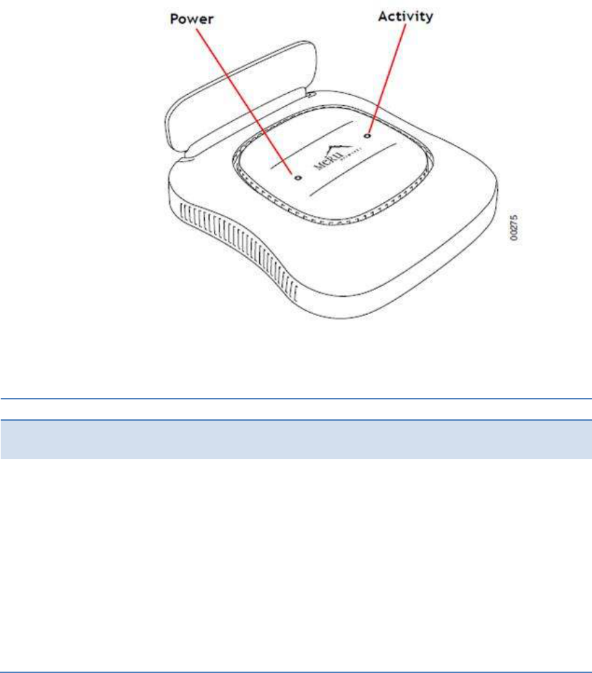
4.8 Check AP433e LED Activity
When AP433e first connects to the controller (and any time the access point is
rebooted), the AP initializes and is then programmed by the controller. When the
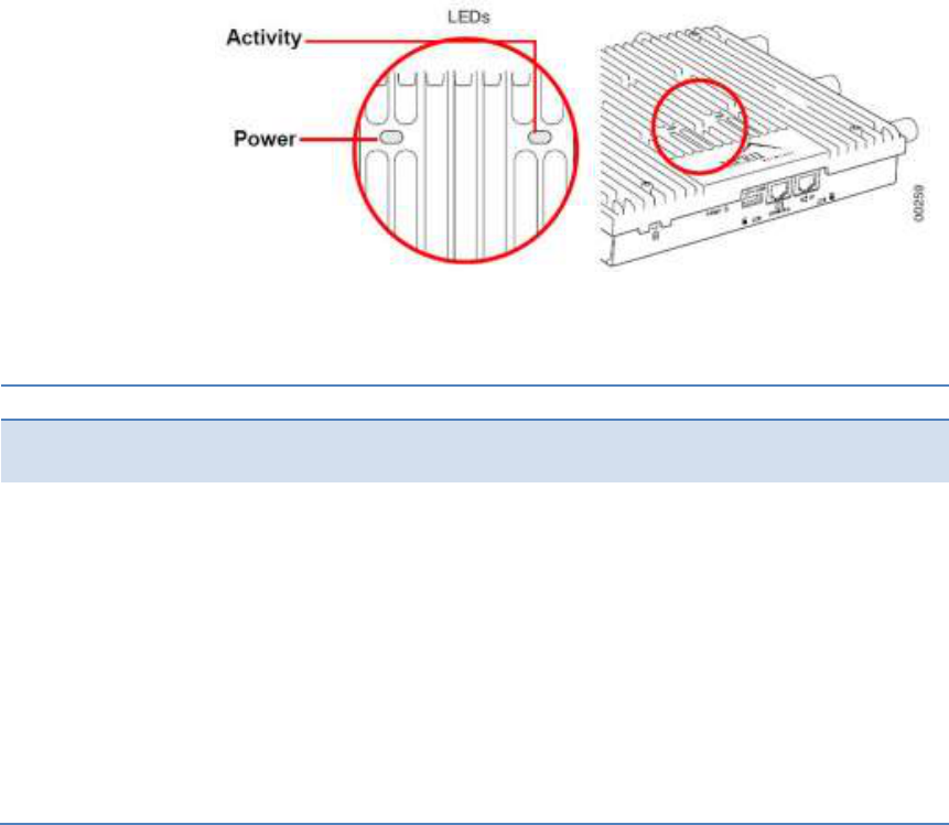
AP first powers up, all LEDs are green as Figure 16, AP433e Status LED
Figure 16, AP433e Status LED
After the AP433e is connected, check the status of the LEDs. The functions of the
LEDs are described below
4.8.1 AP433e LED Description
LED Functions Troubleshooting
Power • Off: No power
• Green: Presence of power
Activity • Off: No power
• Green : Booting stage 1
• Blinking green and off: Booting
stage 2.
• Blinking green and white:
Discovering the controller.
• Blinking green and blue:
Downloading a configuration from
the controller
• Blinking blue and off: AP is online
and enabled, working state
• Blinking red and yellow: Failure;
consult controller for alarm state
• If the status LED is blinking red
and yellow, there is an alarm on
the AP.
• Determine what the alarm is by
clicking Monitor >
Dashboard >Alarms and looking
at the AP alarms.
• You can also use the CLI
commands show alarm and show
log.
4.8.2 Change LED Appearance
If you want to change the appearance of the LEDS, follow these steps:
• From the controller, click Configuration > Devices > AP, and then select
the AP.
• Select one of these settings for the LED Mode setting:
• Normal: LEDs are as described above
• Blink: Sets all LEDs flashing; this is useful to locate an AP
• Dark: Turns off all LEDs
• Click OK.

4.9 Approved Antennas for AP433e
Only approved antennas may be used in conjunction with AP433e access points.
Access Points have been designed to operate with the antennas listed below.
Antennas not included in this list are strictly prohibited for use with these devices.
The required antenna impedance is 50 ohms.
Meru Part Number Gain @ 2.4 GHz Gain @ 5.x GHz Description
ANT-ABGN23O-W 2.0 3.0 Default Antenna. Dual
band Omni directional
dipole antenna
ANT-6ABGN-24 2.5 4.0 Dual band ceiling
mount Omni-directional
6-lead antenna
ANT-ABGN-0406-W 4.0 6.0 Dual band Omni-
directional dipole
antenna
ANT-ABGN-23 3.0 4.0 Dual band ceiling
mount Omni directional
3-lead antenna
ANT-ABGN470 4.7 4.7 Dual band dipole Omni
directional antenna
ANT-I3ABGN-0304-O 3.0 4.0 Dual band ceiling
mount Omni directional
3-lead antenna
ANT-O6ABGN-0606-O 6.0 6.0 Dual band Omni
directional 6-lead
antenna
ANT-O6ABGN-0607-PT 6.0 7.0 Dual band wall mount
patch 6-lead antenna
Note
To deployment ANT-O6ABGN-0607-PT in MESH mode (point to point or point-to-
multiple-points), user will need to drecrease radio tranmit powr 0.3 dBm (TX) to
meet regulatory requirements in 5 GHz band
To deployment ANT-O6ABGN-0607-PT in a non-MESH mode (neither point to
point nor point-to-multiple-points), user will need to drecrease radio tranmit powr
0.3 dBm (TX) to meet regulatory requirements in 5 GHz band
4.10 Where to Go From Here
Now that the AP433e is installed, refer to the Meru System Director Getting
Started Guide for instructions on initializing the hardware. Return to this chapter to
check the status of the LEDs once the WLAN is operational.

5 Installing AP433i & 433is
This chapter describes how to install and configure an AP433i & 433is, which is
supported on System Director Version 6.0-SR1 and later. It contains the following
sections,
• Safety Precautions
• Unpack the AP433i & 433is
• Determine Power Requirements
• Installation Requirements
• Install the AP433i & 433is
• Check AP433i & 433is LED Activity
• Where to Go From Here
5.1 Note
This document depicts installation procedures for the AP433i and 433is models.
Since both devices are externally identical, the same procedures can be used for
either device.
5.2 Safety Precautions
IMPORTANT—Read and follow the regulatory instructions in Appendix B before
installing and operating this Product.
The AP433i & 433is is intended only for installation in Environment A as defined in
IEEE Std 802.3af and 802.3at. All interconnected equipments must be contained
within the same building, including the interconnected equipment's associated
LAN connection.
5.3 Package Content, AP433i & 433is
Confirm that the AP433i & 433is shipping package contains these items:
• AP433i or AP433is
• Plastic attachment (used when paddle antenna is disconnected)
• Wall mounting bracket
• Rubber feet
• Locking pin
• Two mounting screws
5.4 Determine Power Requirements
Power requirements vary, depending on which AP433i & 433is radios are
deployed and what MIMO mode is used. See the chart below for supported power
sources for different radio configurations.
Table 5, Power Source & Radio Supported in AP433
Power Source Radio Supported
IEEE Std 802.3af Radio 1 and Radio 2
IEEE Std 802.3at Radio 1, 2, and 3
5.4.1 IEEE Std 802.3af PoE Usage
When using System Director V6.0 SR2 (or earlier Version) and an IEEE Std

802.3af PoE power source, Meru only supports two radios (radio 0 and 1).
This is because three radios using an IEEE Std 802.3af switch/PoE injector may
not have enough power to operate properly. When using an 802.af PoE, Meru
supports single or dual radios utilizing up to 3 antennas each.
5.4.2 IEEE Std 802.3at PoE Usage
When using System Director V6.0 SR2 (or earlier version) and an IEEE Std
802.3at, all possible configurations are supported (all three radios utilizing up to 3
antennas each). or a list of supported PoEs, see the appendix Supported Power
Over Ethernet Devices for Meru APs.
5.5 Installation Requirements
An array of holes on the mounting bracket allows the AP433i & 433is to be
mounted on the wall and over junction boxes or molly bolts. There are holes for
passing the PoE Ethernet or external power supply cable through the bracket if the
bracket is mounted on a junction box.
The AP433i & 433is has a security cable slot so you can lock the AP433i & 433is
with a standard security cable, such as those used to secure laptop computers.
Purchase optional mounting kits to mount the AP433i & 433is either from the
ceiling or inside an enclosure:
• Above Suspended Ceiling Mounting Kit (T-Bar Hanger): MNT-SCRMKIT-
01
To complete AP433i & 433is installation, you need the items listed below.
Table 6, AP433i & 433is Installation Requirements
Installation Type Item Required
Horizontal mounting • None
Vertical mounting over a wall stud • Four #6 x 2" wood screws for a
wood stud; or
• Four #6 x 1½” metal screws for a
metal stud
• Mounting bracket
Vertical mounting on sheetrock • Four #6 x 1" screws
• Four #4-6 x 7/8” ribbed plastic
wall anchors
• Mounting bracket
Horizontal mounting below a hanging
ceiling
• None
Mounting above a ceiling tile • Mounting bracket MNT-
SCRMKIT
5.6 Additional Equipments
A power source is needed to power the AP433i & 433is. See Determine Power
Requirements.
5.7 Install the AP433i & 433is
This section describes how to install an AP433i & 433is, which is supported on
System Director Version 6.0-SR2 and later. It contains the following subjects,
• Select a Location
• Attach the Provided Antennas
• Install the Access Point
5.7.1 Select a Location
All AP433i interconnected equipment must be contained within the same building,
including the interconnected equipment's associated LAN connection. Ceiling
mounting is recommended but wall mounting is also supported. In addition, the
AP433i should be mounted in a location that meets the following conditions
Relatively unobstructed access to the stations the AP serves. Select a location
with minimal physical obstructions between the AP and the wireless stations. In an
office with cubicles, mounting the APs below a hanging ceiling (plenum is
supported) or the wall near the ceiling provides the least obstructed
communications path. On a wall, orient the AP433i horizontally so that you can
read the Meru logo without tilting your head at 90 degrees - this orientation
provides optimum MIMO performance.
We recommend planning for about 50 clients per radio (or per interference region)
if you plan to use Virtual Port and plan to have phones as clients. For a data-only
installation, plan up to 128 clients per radio, meaning 256 for AP433i. Refer to the
Meru Deployment Guides on the support site for more information.
Access to wall outlet or a to a Power over Ethernet (PoE) connection to the
network switch servicing the controller. AP433i is designed to provide 180 degree
omni-directional coverage as illustrated below. Plan placement with this pattern in
mind.
Figure 17, Coverage pattern of AP433i & 433is when ceiling mounted
Most installations receive the best coverage using the following guidelines:
• Install APs toward the center of the building.
• Place APs about 80 feet apart.
• Do not install APs near metal objects, such as heating ducts, metal doors,
or electric service panels.
5.8 Install the Access Point AP433i & 433is
AP433i & 433is ships with a mounting bracket included in the box. This bracket is
intended for installation as a wall-mount; for mounting on a ceiling, no mount is
typically required. See the following subjects for more specific details.
• Mount AP433i & 433is Horizontally on a Shelf
• Mount AP433i & 433is Vertically on a Wall
• Mount AP433i & 433is Below a Suspended Ceiling
• Mount AP433i & 433is Above a Suspended Ceiling
5.8.1 Mount AP433i & 433is Horizontally on a Shelf
When mounting an AP433i horizontally, no mounting bracket is required. Be sure
to position the paddle antenna vertically when an AP433i sits on a surface. In
order to ensure that the AP433i does not shift much, attach the rubber feet
provided in the box to the bottom of the AP.
5.8.2 Mount AP433i & 433is Vertically on a Wall
Prior to installing the mounting bracket, it is recommended that users remove the
protective plastic shell from the AP. This makes it easier to properly lock the
device in place once it is mounted. To remove the shell, flip the AP upside-down
and release the four locking clips from the AP itself, as indicated in Figure 18,
AP433i & 433is Shell Clip Locations
Figure 18, AP433i & 433is Shell Clip Locations
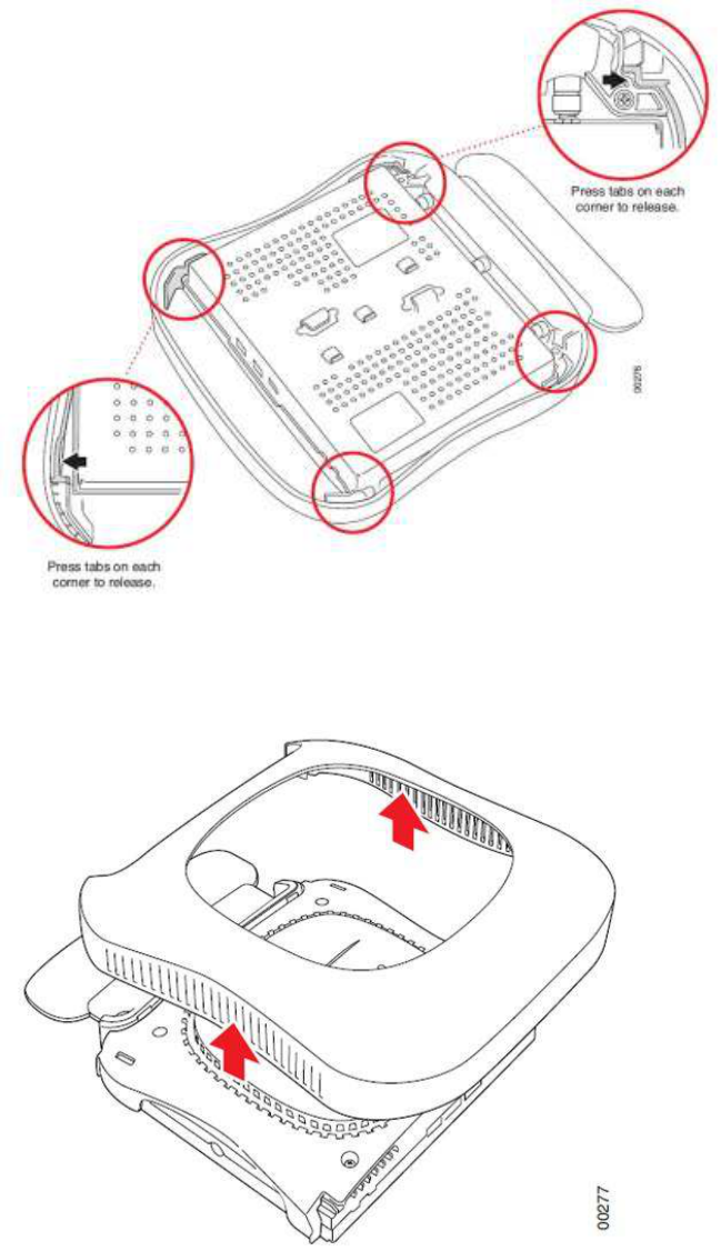
After unclipping the shell, it is a simple matter to lift it off of the main AP. See
Figure 19, Removing AP433i & 433is shell
Figure 19, Removing AP433i & 433is shell
You are now ready to proceed with the wall mounting procedure.
To mount an AP433i on a wall, use the provided mounting bracket, as shown in
Figure 20, AP433i & 433is wall mounting bracket
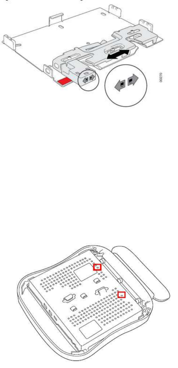
Figure 20, AP433i & 433is wall mounting bracket
• Place the mounting bracket against the wall with the sliding lock
mechanism facing upwards. The Quick Reference Installation instructions
on the bracket should be visible.
• Using the holes on the mounting bracket itself as a guide, mark the
location on the wall for the AP bracket mounting screws. If possible,
center the mounting screws on a wall stud. (If mounting on a wall stud is
impossible, use plastic wall anchors on the remaining screws.)
• Drill holes at the locations you marked:
o 3/16-inch holes if you are using plastic anchors
o 1/8-inch holes if you are using only the screws
• If you are using plastic anchors, install them in the holes.
• Line the bracket up with the holes and screw in the screws.
• Attach the mounting screws to the underside of the AP433i in the holes
provided (indicated in Figure 21, AP433i & 433is mounting screw holes)
Figure 21, AP433i & 433is mounting screw holes
• Orient the AP433i horizontally so that you can read the Meru logo and
the Console and network ports are pointed downwards - this orientation
provides optimum MIMO performance.
• Align the mounting screws on the back of the AP433i with the
corresponding holes on the mounting
• bracket.
• Slide the AP433i downwards until the screws click into the holes. They
should seat fairly firmly.
• Slide the mounting bracket’s locking bar to the right, locking the AP in
place.
• If desired, use the provided clip to lock the bracket shut by sliding it
through the aligned holes on the right-hand side of the bracket.See
Figure 22, Locking the AP433i & 433is in Place
Figure 22, Locking the AP433i & 433is in Place
• Connect one end of the Ethernet cable to the switch and the other end to
the AP433i
Figure 23, Ports for AP433i & 433is
Caution!
Be sure to connect the Ethernet cable to the Ethernet port; the cable can
mistakenly be plugged into the Console port. If you do this, the AP won’t
power up
5.8.3 Mount AP433i & 433is below a Suspended Ceiling
The brackets on the bottom of the AP433i allow it to be mounted directly to a ceiling T-
bar (see Figure 24, Mounting AP433i & 433is to a Suspended Ceiling Rail). Note that
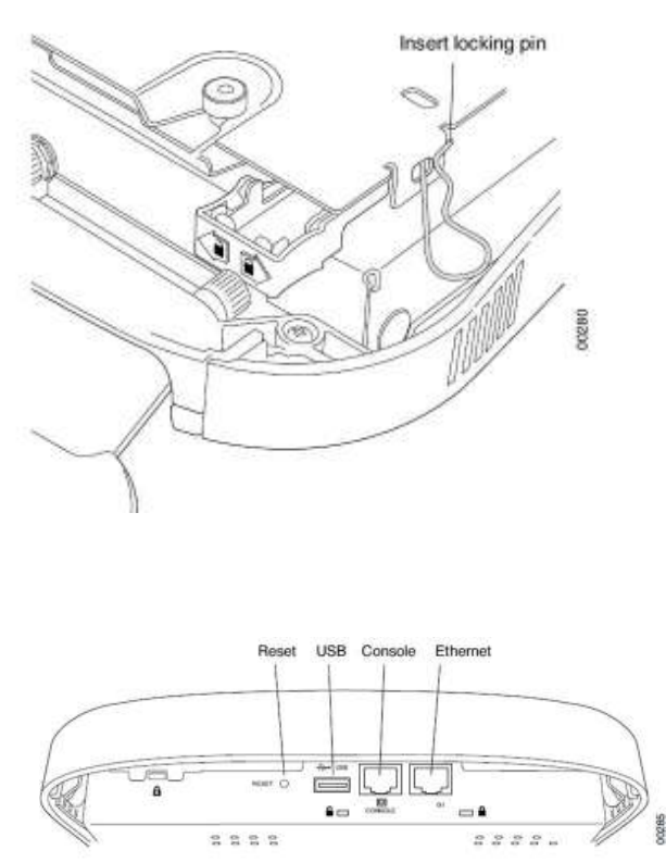
the AP lock must be disabled by sliding the locking key (provided in the box) into the
unlock hole on the side of the AP shown inFigure 23, Ports for AP433i & 433is in order
to clip the AP in place.
Figure 24, Mounting AP433i & 433is to a Suspended Ceiling Rail
To mount an AP433i below a suspended ceiling:
• Determine the location on the ceiling rail where the AP will be mounted
and remove the ceiling tiles.
• Verify that the AP is unlocked using the locking key on the unlock
mechanism (on the same side as the Ethernet ports).
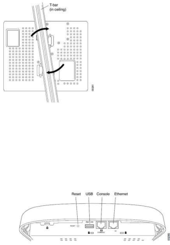
• Press the AP433i against the T-bar at a slight angle and then rotate into
place, as indicated in Figure 24, Mounting AP433i & 433is to a
Suspended Ceiling Rail. You should hear it snap in place.
• Connect one end of the PoE Ethernet cable to the AP’s Ethernet port
(see Figure 25, Ports of AP433i & 433is)
Figure 25, Ports of AP433i & 433is
Caution!
Be sure to connect the Ethernet cable to the Ethernet port; the cable can
mistakenly be plugged into the Console port. If you do this. the AP won’t power up.
5.9 Check AP433i & 433is LED Activity
When AP433i & 433is first connects to the controller (and any time the access
point is rebooted), the AP initializes and is then programmed by the controller.
When the AP first powers up, all LEDs are green
Figure 26, AP433i & 433is LEDs
After the AP433i & 433is is connected, check the status of the LEDs. The
functions of the LEDs are described below
5.9.1 AP433i & 433is LED Description
LED Functions Troubleshooting
Power • Off: No power
• Green: Presence of power
Activity • Off: No power
• Green : Booting stage 1
• Blinking green and off: Booting
stage 2.
• Blinking green and white:
Discovering the controller.
• Blinking green and blue:
Downloading a configuration from
the controller
• Blinking blue and off: AP is online
and enabled, working state
• Blinking red and yellow: Failure;
consult controller for alarm state
• If the status LED is blinking red
and yellow, there is an alarm on
the AP.
• Determine what the alarm is by
clicking Monitor >
Dashboard >Alarms and looking
at the AP alarms.
• You can also use the CLI
commands show alarm and show
log.
5.9.2 Change LED Appearance
If you want to change the appearance of the LEDS, follow these steps:
• From the controller, click Configuration > Devices > AP, and then select
the AP.
• Select one of these settings for the LED Mode setting:
o Normal: LEDs are as described above
o Blink: Sets all LEDs flashing; this is useful to locate an AP
o Dark: Turns off all LEDs
• Click OK.
5.10 Where to Go From Here
Now that the AP433i & 433is is installed, refer to the Meru System Director Getting
Started Guide for instructions on initializing the hardware. Return to this chapter to
check the status of the LEDs once the WLAN is operational.
6 Installing OAP433e
This chapter describes how to physically install an OAP433e, which is supported
on System Director Versions 6.0 SR2 and later. It contains the following sections:
• Unpacking the OAP433e
• Installation Requirements
• Assembling the Waterproof Ethernet Connector
• Installing the Access Point
• Where to Go From Here
• Unpacking the OAP433e
Note
Please use the OAP433 series only with Listed ITE or equivalently-rated
equipment.
6.1 Unpacking the OAP433e
Confirm that the OAP433e shipping boxes contain the following items (see Figure
27, OAP433e outdoor access point (top & bottom)
• OAP433e Outdoor Access Point
• Water barrier for the Ethernet connection (when shipped, this is not
connected to the AP)
• Wall/Pole Mount Hardware Kit for mounting OAP433e to a 2” to 3”
diameter steel pole or tube or as part of a radio or tower structure (3
pieces)
• Screws and bolts for assembling the mounting bracket
• Drywall screws (for wall-mounted installation)
• Ground wire
Figure 27, OAP433e outdoor access point (top & bottom)
6.2 Installation Requirements
In addition to the hardware supplied by Meru Networks, you need the following
required accessories.
• Antennas (sold separately)
• RF coaxial cable to connect the antennas to the OAP433e
• Drill (if wall-mounting)
• Crescent wrench
• Outdoor CAT5 Ethernet cable, Cable type CMX
o Size 22 (American Wire Gauge) with a 3.8mm gap
o Size 24 (AWG) with a 3mm gap
Note
The Ethernet cable must be run through the OAP433e’s water-tight input port,
which is provided in the package. This will ensure a waterproof seal around the
connection. Follow the instructions listed later in this chapter to properly install the
cable.
6.3 Power Requirements
The OAP433e does not ship with a power adapter, and as such, must be powered
by a PoE device. In order to ensure that all three radios on the AP are active, it
must be plugged into an 802.3at power source. If an 802.3af source is used, the
third radio will be disabled due to insufficient power.
6.4 Assembling the Waterproof Ethernet Connector
The OAP433 ships with a separate Ethernet connector that must be disassembled
in order to run a cable through it. Once tightened and connected to the AP itself,
this connector will ensure a waterproof seal for the AP.
To run an Ethernet cable through the waterproof connector:
• Unscrew the two main components of the connector.
• Remove the insert from the larger portion of the connector. This should
be a rubber casing surrounded by a plastic shell. Both the plastic shell
and the rubber casing should have a slit along one side, allowing them to
be opened up in order to insert the cable.
• Prior to attaching the rubber casing to the cable, run the cable through
the smaller portion of the original two-part enclosure. Be sure to run the
cable through the smaller opening (at the top of the plastic component)
so that the head of the cable goes towards the AP. (Note that this step
can be done after the rest of the connector has been assembled, but it
can be difficult to do so when deploying long cables, so it’s best to do it
here instead.)
• Run the Ethernet cable through the slit in the rubber casing and ensure
that the casing wraps firmly around the cable. The Ethernet connector at
the end of the cable should be on the larger side of the rubber casing.
• Replace the larger plastic component (the one that has threading on both
ends) such that it fits around the rubber casing with the plastic shell. The
portion of the component with a large rubber washer should be facing the
end of the Ethernet cable (which will be connected to the AP).
• Connect the Ethernet cable to the port on the AP and screw the plastic
threading in place. This should be tightened firmly, but should not require
excessive force.
• Finally, screw the last plastic portion to the top of the threading. Again,
tighten this firmly, but not excessively. The gap between the top cap and
the base of the threading component should be 3mm when using a
24AWG cable or 3.8mm when using a 22AWG cable.
Now that the Ethernet cable connection has been fully assembled, the AP is ready
to be deployed.
6.5 Installing the Access Point
When you plan the OAP433e physical configuration, include the elements shown
in this Figure 28, SAmple physical layout
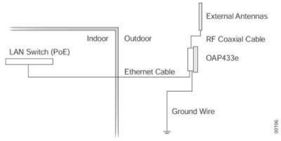
Figure 28, SAmple physical layout
6.6 Radio Position Planning
Never construct a radio mast, pole, or tower near overhead power lines. In
addition, local regulations may limit or prevent construction of a high radio mast or
tower. If your OAP433e link requires a high radio mast or tower, consult a
professional contractor for advice. Once the required antenna height has been
determined, other factors affecting the precise position of the OAP433e must be
considered.
• Be sure there are no other radio antennas within 2 m (6 ft.) of the
OAP433e.
• Place the OAP433e away from power and telephone lines.
• Avoid placing the OAP433e too close to any metallic, reflective surfaces,
such as roof-installed air-conditioning equipment, tinted windows, wire
fences, or water pipes.
6.7 Radio Interference
Avoiding radio interference is an important part of wireless planning. Interference
is caused by other radio transmissions using the same or an adjacent channel
frequency. You should first scan your proposed site using a spectrum analyzer to
determine if there are any strong radio signals using the 2.4 or 5 GHz spectrums.
Always use a channel frequency that is furthest away from another signal on the
spectrum.
6.8 Weather Conditions
Take into account any extreme weather conditions that are known to affect your
location. Consider these factors:
• Temperature — The OAP433e is tested for normal operation in
temperatures from - 40°F to 140°F. Operating in temperatures outside of
this range may cause the unit to fail.
• Wind Velocity — The OAP433e can operate in winds up to 44 m/s and
survive higher wind speeds up to 66 m/s. You must consider the known
maximum wind velocity and direction at the site and be sure that any
supporting structure, such as a pole, mast, or tower, is built to withstand
this force.
• Lightning — You should make sure that the unit, any supporting structure,
and cables are all properly grounded. Additional protection using lightning
rods, lightning arrestors, or surge suppressors may also be employed in
order to protect against lightning strikes on the antennas. Contact Meru
Sales for more information regarding this equipment.
• Rain — The OAP433e is weatherproofed against rain. Also, prolonged
heavy rain has no significant effect on the radio signal. However, it is
recommended to apply weatherproof sealing tape around the Ethernet
port and antenna connectors for extra protection. If moisture enters a
connector, it may cause a degradation in performance or even a
complete failure of the link.
• Snow and Ice — Falling snow, like rain, has no significant effect on the
radio signal. However, a build up of snow or ice on antennas may cause
the link to fail.In this case, the snow or ice has to be cleared from the
antennas to restore operation of the link.
6.9 Ethernet Cabling
When a suitable antenna location has been determined, plan a cable route from
the OAP433e outdoors to the PoE-enabled controller indoors. Consider these
points:
• The Ethernet cable length should never be longer than 100 ft.
• Determine a building entry point for the cable.
• Determine if conduits, bracing, or other structures are required for safety
or protection of the cable.
• For lightning protection at the controller end of the cable, consider using
a lightning arrestor immediately before the cable enters the building.
• The shield of the ethernet cable needs to be grounded at the lightning
arrestor. If, by design, the lightning arrestor cannot provide this ground,
the shield of the ethernet cable will need to be grounded by the installer.
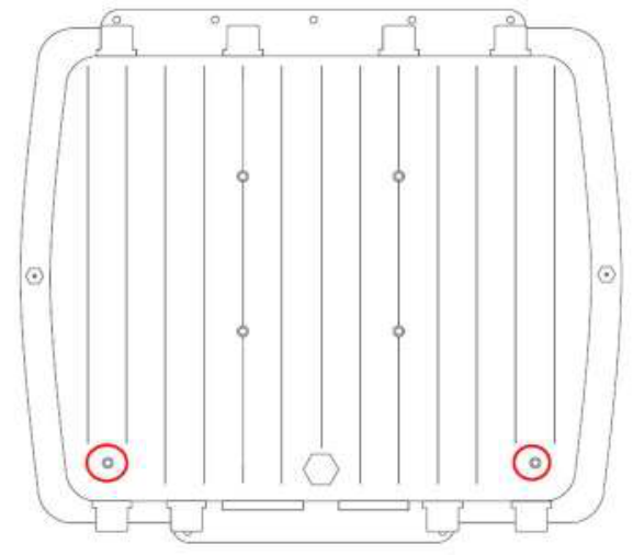
6.10 Grounding
It is important that the OAP433e, cables, and any supporting structures are
properly grounded. The OAP433e unit includes a grounding screw to attach a
ground wire. (See Figure 29, OAP433e grounding holes) for grounding screw
locations.) Be sure that grounding is available and that it meets local and national
electrical codes.
Figure 29, OAP433e grounding holes
6.11 Test Basic Link Operation
Prior to deploying the AP, it is recommended that users connect it to an existing
Meru deployment in order to ensure basic functionality. This can be done indoors
in a controlled setting, prior to going through the trouble of mounting it externally.
To do so, simply connect the AP to an existing controller and verify that the
controller recognizes it. If so, proceed with the following section in order to deploy
the AP.
6.12 Mounting the Access Point
The OAP433e can be mounted on the following (brackets are included):
• 2 to 3 inch diameter pole
• Wall
6.12.1 Mounting OAP433e with the Pole-Mounting Bracket
Be sure to attach antennas (see Connecting Antennas and Ground Wire to
OAP433e) before mounting an OAP433e on a pole. Follow these steps to mount
the unit to a 2 to 3 inch diameter steel pole or tube using the mounting bracket:
• Attach the OAP433e to the square portion of the mounting bracket by
placing the bracket flat against the bottom of the AP and inserting screws
into the corners of the bracket portion. The holes on the bracket should
correspond to the holes on the bottom of the AP. See Figure 30, Square
mounting bracket attached to bottom of OAP433e.
Figure 30, Square mounting bracket attached to bottom of OAP433e
Note that the circular portion of the bracket should be facing to the side of the P
(the AP’s sides are the faces that do not have antennas or other attachments).
This is to ensure that the AP is properly oriented when the bracket is fully
assembled.
• Next, identify the portion of the bracket assembly that inserts into the
circular opening on the portion currently attached to the AP. The correct
component has a corresponding circular section with a hollow cone
protruding from one face of it. See Figure 31, Second bracket attachment
Figure 31, Second bracket attachment
• Insert the cone into the circular portion of the bracket attached to the AP.
The two should fit somewhat snugly, although a screw assembly will be
required to hold them in place.
• Run one of the long screws provided in the package down through the
hole that runs through both portions of the bracket. The head of the
screw should fit into the hexagonal slot on the top of the bracket
assembly.
• On the other end of the screw (i.e., the one that doesn’t have the
hexagonal head), slide a flat washer and then a lock washer into place.
The flat washer should be against the base of the mounting assembly.
• Screw one of the hexagonal nuts into place on top of the two washers.
Once tightened, the nut should force the lock washer into place and the
two bracket components should be locked together.
• At this point, locate the third portion of the bracket. It should be shaped
like a small, wide ‘v’. This part will be used to brace against the backside
of the pole.
• Place the opening of the ‘v’ bracket against the pole and hold the
OAP433e (with attached bracket assembly) up opposite it. The holes on
either end of the ‘v’ bracket should align with the two middle holes on the
‘v’ portion of the bracket attached to the AP.
• Slide the two remaining long screws from the package contents into the
corresponding holes. The hexagonal head of each screw should be on
the bracket end that faces the AP (i.e., on the end that is already
attached to the AP itself).
• Again, slide a flat washer followed by a lock washer and a hexagonal nut
onto the bottom of each screw.
• Tighten the securing nuts just enough to hold the bracket to the pole.
(The bracket may need to be rotated around the pole during the
alignment process.)
• Rotate/orient the AP as desired, then tighten the nuts securely in place.
• Connect the Ethernet cable to the controller inside the building and verify
that all antennas are securely connected.
Note
When fully deployed, the Meru logo on the top of the AP should be right-side up.
This will ensure that the Ethernet cable is oriented downwards when the entire
bracket is assembled. Make sure that the AP is properly oriented before tightening
everything in place on the pole.
6.12.2 Mounting OAP433e with the Wall-Mounting Bracket
Attach the bracket to a wall with the flat side flush against the wall. Follow these
steps to mount the unit to a wall using the wall-mounting bracket:
• Prior to attaching the bracket to the AP, it is important to drill the required
holes in the wall and insert the sheetrock anchors provided in the AP
package. One of the three included bracket components consists of a
circular portion (with a hollow cone in the center) connected to a wide ‘v’-
shaped portion. Use the ‘v’-shaped portion as a guide.
• Place the ‘v’ component against the wall at the desired location and mark
the four holes (one at each corner of the bracket) on the wall.
Note
Note that the bracket must be oriented such that the wider portions of the bracket
are its top and bottom when placed against the wall. This will ensure that the fully
deployed AP will be oriented properly (with the Ethernet cable leading downwards).
• Remove the bracket and drill the corresponding holes. When finished,
insert the plastic sheetrock anchor inserts into each hole drilled.
• Place the bracket against the wall again and use the screws provided
with the plastic anchors to attach it to the wall.
• Using the portion of the bracket assembly that has a flat component
attached to another circular portion (seeFigure 32, Square mounting
bracket), attach the OAP433e to the square portion of the mounting
bracket by placing the bracket flat against the bottom of the AP and
inserting screws into the corners of the bracket portion. The holes on the
bracket should correspond to the holes on the bottom of the AP. Figure
33, Square mounting bracket attaches to bottom of OAP433e
Figure 32, Square mounting bracket
Figure 33, Square mounting bracket attaches to bottom of OAP433e
Note
Note that the circular portion of the bracket should be facing to the side of the AP
(the AP’s sides are the faces that do not have antennas or other attachments).
This is to ensure that the AP is properly oriented when the bracket is fully
assembled.
• Insert the circular portion of the bracket attached to the AP into the hollow
cone portion of the bracket on the wall. The two should fit somewhat
snugly, although a screw assembly will be required to hold them in place.
• Run one of the long screws provided in the package down through the
hole that runs through both portions of the bracket. The head of the
screw should fit into the hexagonal slot on the top of the bracket
assembly.
• On the other end of the screw (i.e., the one that doesn’t have the
hexagonal head), slide a flat washer and then a lock washer into place.
The flat washer should be against the base of the mounting assembly.
• Screw one of the hexagonal nuts into place on top of the two washers.
Once tightened, the nut should force the lock washer into place and the
two bracket components should be locked together.
• Connect the Ethernet cable to the controller and verify that all antennas
are securely connected.
6.12.3 Connecting Antennas and Ground Wire to OAP433e
OAP433e does not ship with any antenna by default. Since customers have
different outdoor applications, we suggest that you choose from the various
antenna options offered by Meru. See the list in Optional External Antennas.
The OAP433e works both with antennas that attach directly to the unit and remote
antennas. When using antennas that attach to the unit, attach the antennas before
installing the unit. When deploying an OAP433e with remote antennas, first mount
remote antennas and then connect them to the AP. If you aren’t planning on using
some of the antennas, be sure to terminate the connections with antenna
terminators in order to prevent excess transmissions from unused connectors.
Note
Although there are three radios in the OAP433e, space constraints allow for only
eight antennas to be connected to the AP. Consequently, Radio 1 only supports
two antennas. See Figure 34, Antenna-Radio Mapping for OAP433e & Figure 35,
Antenna-Radio Mapping & Radio Settingfor details on which antennas correspond
to each radio
Figure 34, Antenna-Radio Mapping for OAP433e
Figure 35, Antenna-Radio Mapping & Radio Setting
Follow these steps to connect antennas:
• Remove the protective dust caps from the antenna connectors.
• Mount the external antenna on the same supporting structure as you did
the OAP433e, within 3 m (10 ft.) of it, using the bracket supplied in the
antenna package.
• Connect the antenna to the OAP433e’s N-type connector (5G-1 and
2.4G-1) using the RF coaxial cable provided in the antenna box.
• Apply weatherproofing tape to the antenna connectors to help prevent
water entering the connectors.
Follow these steps to attach the ground wire:
• A grounding screw and cable are both provided in the product packaging.
The OAP433e has two grounding holes, in the corners on the underside
of the AP. See Figure 36, Grounding holes
• Connect the screw to either of the holes and attach the provided
grounding wire.
• Attach the other end of the grounding wire to an appropriate grounding
source.
Figure 36, Grounding holes

Note
When not using antenna connectors on the OAP433e, keep the covers securely
attached for weather protection. Once the AP is deployed, these unused
connectors must be properly terminated.
Caution!
Caution! Equipment shall be installed in accordance with the National Electrical
Code ANSI/NFPA 70 and the Canadian Electrical Code, Part 1, and when
applicable, the National Electrical Safety Code, IEEE C2.
Equipment shall be properly grounded according to Chapter 8 of ANSI/NFPA 70,
the National Electrical Code (NEC) and the Cable distribution system should be
grounded (earthed) in accordance with ANSI/NFPA 70, the National Electrical
Code (NEC), in particular Section 820.93, Grounding of the Outer Conductive
Shield of a Coaxial Cable.
The separate protective earthing terminal provided on this product shall be
permanently connected to earth.
6.13 Approved Antennas for OAP433e
Only approved antennas may be used in conjunction with OAP433e access points.
Access Points have been designed to operate with the antennas listed below.
Antennas not included in this list are strictly prohibited for use with these devices.
The required antenna impedance is 50 ohms.
Meru Part Number Gain @ 2.4 GHz Gain @ 5.x GHz Description
ANT-A08O-NM-1 NA 8.0 (5150~5350
MHz) Omnidirectional
antenna, 5150 - 5350
MHz (US, Non-DFS
band UNII-1), N-type
connector
ANT-A08O-NM-2 NA 8.0 (5470 ~5875
MHz) Omnidirectional
antenna, 5470 - 5875
MHz (US, EMEA,
Others, DFS band UNII-
2 & UNII-2e), N-type
connector
ANT-BG08O-NM 8.0 NA Omnidirectional
antenna, 2400 - 2500
MHz Worldwide, N-type
connector
ANT-O4ABGN-0606-O-N 6.0 6.0 Dual band wall-mask
mount omnidirectional
outdoor, N-type
connector with 4 RG58
coaxial cable leads
ANT-O4ABGN-0607-PT-N 6.0 7.0 Dual band wall-mask
mount directional patch
outdoor, N-type
connector with 4 RG58
coaxial cable leads
6.14 Installation with ANT-O4ABGN-0606-O-N
The following diagram show the installation with Installation with ANT-O4ABGN-
0606-O-N antenna. See Figure 37, OAP433e deployment with ANT-O4ABGN-
0606-O-N antenna in ETSIFigure 38, OAP433e deployment with ANT-O4ABGN-
0606-O-N antennas & Figure 38, OAP433e deployment with ANT-O4ABGN-0606-
O-N antennas
Figure 37, OAP433e deployment with ANT-O4ABGN-0606-O-N antenna in ETSI
Figure 38, OAP433e deployment with ANT-O4ABGN-0606-O-N antennas in US/IC
6.15 Installation with ANT-O4ABGN-0607-PT-N
The following diagram show the installation with Installation with ANT-O4ABGN-
0607-PT-N antenna. Figure 39, OAP433e deployment with ANT-O4ABGN-0607-
PT-N antenna in FCC/IC & Figure 40, OAP433e deployment with ANT-O4ABGN-
0607-PT-N antenna
Figure 39, OAP433e deployment with ANT-O4ABGN-0607-PT-N antenna in FCC/IC
Figure 40, OAP433e deployment with ANT-O4ABGN-0607-PT-N antenna in FCC/IC
Note
To deployment ANT-O4ABGN-0607-PT-N antenna in MESH mode (point to point
or point-to-multiple-points), user will need to drecrease radio tranmit powr 0.3 dBm
(TX) to meet regulatory requirements in 5 GHz band.
To deployment ANT-O4ABGN-0607-PT-N antenna in non-MESH mode (neither
point to point nor point-to-multiple-points), user will need to drecrease radio tranmit
powr 1.0 dBm (TX) to meet regulatory requirements in 5 GHz band.
6.16 Installation with ANT-A08O-NM-1/2 & BG08O-NM
The following diagram show the installation with Installation with ANT-A08O-NM-1,
ANT-A080-NM-2, and ANT-BG08O-NM with OAP433e.Figure 41, OAP433e
deployment with ANT-A08O-NM-1 or 2 & BG08O-NM antenna in FCC/IC & Figure
42, OAP433e deployment with ANT-A080-NM-1 or 2 & BG-080-NM antenna in
ETSI
Figure 41, OAP433e deployment with ANT-A08O-NM-1 or 2 & BG08O-NM antenna in
FCC/IC
Figure 42, OAP433e deployment with ANT-A080-NM-1 or 2 & BG-080-NM antenna in
ETSI
Note
To deployment ANT-A080-NM-1 or 2 & ANT-BG080-NM in MESH mode (point to
point or point-to-multiple-points), user will need to drecrease radio tranmit powr 0.6
dBm (TX) to meet regulatory requirements in both 5 GHz band & 2.4 GHz band.
To deployment ANT-A080-NM-1 or 2 & ANT-BG080-NM in a non-MESH mode
(neither point to point nor point-to-multiple-points), user will need to drecrease
radio tranmit power 2 dBm (TX) to meet regulatory requirements in both 5 GHz
band & 2.4 GHz band.
6.17 Where to Go From Here
Now that the OAP433e is installed, go to the Meru System Director Getting
Started Guide for instructions on initializing the hardware. Return to this chapter to
check the status of the LEDs once the WLAN is operational.
As well, check the AP chapter in the Meru System Director Configuration Guide for
instructions on configuring radio band, dual radio, and external antenna operation.

7 Regulatory Information
The Meru Access Point (APs) must be installed and used in strict accordance with
the manufacturer’s instructions as described in the user documentation that comes
with the product. For country-specific approvals, see below. Meru Networks, Inc. is
not responsible for any radio or television interference caused by unauthorized
modification of APs, or the substitution or attachment of connecting cables and
equipment other than that specified by Meru Net- works, Inc. The correction of
interference caused by such unauthorized modification, substitution or attachment
is the responsibility of the user. Meru Networks, Inc. and its authorized resellers or
distributors are not liable for any damage or violation of government regulations
that may arise from the user failing to comply with these guidelines.
7.1 Regulatory Specifications
Category Items
Safety UL 60950-1
CSA C22.2
EN 60950-1
IEC 60950-1
Unintentional Radiation
Compliance FCC Part 15.107 - 47CFR15.107
FCC Part 15.109 - 47CFR15.109
ICES-003
EN 301 489-1
EN 301 489-17
EN55022
EN55024/AS/NZS CISPR 24
Intentional Radiation
Compliance FCC Part 15.247 - 47 CFR Ch. I
FCC Part 15.407 - 47 CFR15.407
RSS-210
EN 300 328
EN 301 893
7.2 Declaration of Conformity, Federal Communication
Commission
7.2.1 Manufacturer Information
Meru Networks, Inc
894 Ross Drive, Sunnyvale, CA 94089, USA
7.2.2 Declaration of Conformity
This device complies with Part 15 rules. Operation is subject to the following two
conditions:
This device may not cause harmful interference, and
This device must accept any interference received, including interference that may
cause undesired operation.
Device Name FCC ID Number
AP433e RE7-AP433E
AP433i RE7-AP433I
AP433is RE7-AP433is
OAP433e RE7-OAP433E
This product is FCC marked according to the provisions of FCC Part 15.

This equipment has been tested and found to comply with the limits of a Class B
digital device, pursuant to Part 15 of the FCC Rules. These limits are designed to
provide reasonable protection against harmful interference when the equipment is
operated in a residential environment. This equipment generates, uses, and
radiates radio frequency energy, and if not installed and used in accordance with
the instructions, may cause harmful interference. How- ever, there is no guarantee
that interference will not occur. If this equipment does cause inter- ference to radio
or television reception, which can be determined by turning the equipment off and
on, the user is encouraged to correct the interference by one of the following
measures:
Reorient or relocate the receiving antenna.
Increase separation between the equipment and receiver.
Connect the equipment to an outlet on a circuit different from which the receiver is
connected.
Consult the dealer or an experienced radio/TV technician.
Note
The Part 15 radio device operates on a non-interference basis with other devices
operating at this frequency when using the integrated antennas. Any changes or
modification to the product not expressly approved by Meru could void the user's
authority to operate this device.
7.3 Declaration of Conformity, Industry Canada
This equipment is in compliance with the essential requirements of other relevant
provisions of Directive.
7.3.1 Manufacturer Information
Meru Networks, Inc
894 Ross Drive, Sunnyvale, CA 94089, USA
7.3.2 Declaration of Conformity
The Class B digital portion of this apparatus complies with Canadian standard
ICES-003. These devices comply with RSS210 of Industry Canada.
La partie numérique de Classe B de cet appareil est conforme à la norme ICES-
003 canadien. Ces appareils sont conformes à la norme RSS 210 d'Industrie
Canada..
Per RSS 210 A9.5 point 7:
The device for the band 5150-5250 MHz is only for indoor usage to reduce
potential for harmful interference to co-channel mobile satellite systems (The
device for the band 5150-5250 MHz is only for indoor usage to reduce potential for
harmful interference to co-channel mobile satellite systems)
The maximum antenna gain permitted (for devices in the bands 5250-5350 MHz
and 5470-5725 MHz) to comply with the EIRP limit; and the maximum antenna
gain permitted (for devices in the band 5725-5825 MHz) to comply with the EIRP
limits specified for point-to-point and non point-to-point operation as appropriate,
as stated in section A9.2(3) (The maximum antenna gain permitted (for devices in
the bands 5250-5350 MHz and 5470-5725 MHz) to comply with the EIRPlimit; and
the maximum antenna gain permitted (for devices in the band 5725-5825 MHz) to
comply with the EIRP limits specified for point-to-point and non point-to-point
operation as appropriate, as stated in section A9.2(3).
In addition, users should also be cautioned to take note that high-power radars are
allocated as primary users (meaning they have priority) of the bands 5250-5350
MHz and 5650-5850 MHz and these radars could cause interference and/or
damage to WLAN devices (En outre, les utilisateurs doivent également être avertis
de prendre note que les radars à haute puissance sont désignés comme
utilisateurs principaux (ils ont la priorité) des bandes 5250-5350 MHz et 5650-
5850 MHz et ces radars pourraient cause des interférences et / ou endommager

aux appareils WLAN.
These devices are not permitted to operate in the 5600 - 5650 MHz band (Ces
appareils ne sont pas autorisés à opérer dans le 5600 - bande 5650 MHz.)
For products available in the Canadian markets, only channels 1 through 11 can
be operated. Selection of other channels is not authorized. Operation is subject to
the following two conditions: (1) this device may not cause interference, and (2)
this device must accept any interference, including interference that may cause
undesired operation of this device.
Pour les produits disponibles sur les marchés canadiens, seuls les canaux 1 à 11
peuvent être utilisés. La sélection d'autres canaux n'est pas autorisée. Son
fonctionnement est soumis aux deux conditions suivantes: (1) cet appareil ne doit
pas provoquer d'interférences et (2) cet appareil doit accepter toute interférence, y
compris celles pouvant causer un mauvais fonctionnement de ce dispositif
This device and its listed antenna(s) must not be co-located or operated in
conjunction with any other antenna or transmitter
Cet appareil et son antenne énuméré (s) ne doivent pas être situés ou exploités
conjointement avec une autre antenne ou transmetteur
The term "IC" before the equipment certification number only signifies that the
Industry Can- ada technical specifications were met.
Le terme “IC” avant le numéro de certification de l'équipement signifie seulement
que les spécifications techniques d'Industrie Ca-nada ont été atteints
To reduce the potential radio interference to other users, the antenna type and
gain should be chosen so that the equivalent isotropic radiated power (EIRP) is
not more than that required for successful communication. This device complies
with Class B Limits of Industry Canada. Operation is subject to the following two
conditions:
Pour réduire le risque d'interférence avec d'autres utilisateurs, le type d'antenne et
le gain doivent être choisis de telle sorte que la puissance isotrope rayonnée
équivalente ne soit pas supérieure à celle requise pour une communication
réussie. Cet appareil est conforme aux limites de Classe B d'Industrie Canada.
Son fonctionnement est soumis aux deux conditions suivantes
This device may not cause harmful interference, and
Cet appareil ne doit pas provoquer d'interférences nuisibles, et
This device must accept any interference received, including interference that may
cause undesired operation.
Cet appareil doit accepter toute interférence reçue, y compris les interférences
pouvant entraîner un fonctionnement indésirable.
To prevent radio interference to the licensed service, this device is intended to be
operated indoors and away from windows to provide maximum shielding.
Equipment (or its transmit antenna) that is installed outdoors is subject to licensing.
Pour empecher que cet appareil cause du brouillage au service faisant l’objet
d’une licence, il doit etre utilze a l’interieur et devrait etre place lin des fenetres afin
de Fournier un ecram de blindage maximal. Si le matriel (ou son antenne
d’emission) est installe a l’exterieur, il doit faire l’objet d’une licence.
Device Name (Nom de l'appareil) Industry Canada ID Number (Industrie
Canada Numéro d'identification)
AP433e 6749A-AP433E
AP433is 6749A-AP433I
AP433is 6749A-AP433IS
OAP433e 6749A-OAP433E
7.4 Declaration of Conformity, R&TTE Directive 1999/5/EC
This equipment is in compliance with the essential requirements of other relevant
provisions of Directive.
7.4.1 Manufacturer Information

Meru Networks, Inc
894 Ross Drive, Sunnyvale, CA 94089 USA
7.4.2 Declaration of Conformity
The following standards were applied:
EMC-EN 301.489-1 Article 3.1 (b) of R&TTE Directive; EN 301.489-17 Article 3.1
(b) of R&TTE Directive
Health & Safety-EN60950-1
Radio-EN 300 328 Article 3.1 (b) of R&TTE Directive; EN 301.893 Article 3.1 (b) of
R&TTE Directive
The conformity assessment procedure referred to in Article 10.4 and Annex III of
Directive 1999/5/EC has been followed.
This product is CE marked according to the provisions of the R&TTE Directive
(1999/5/EC). Meru Networks Inc., hereby declares that this 433 SERIES AP
models are in compliance with the essential requirements and other relevant
provisions of Directive 1999/5/EC.
Language Content of Declaration
Български
(Bulgarian)
това оборудване е в съответствие със съществените изисквания и
другите приложими разпоредби на Директива 1999/5/ЕО
Češka
(Czech)
Toto zařízení je ve shodě se základními požadavky a dalšími příslušnými
ustanoveními směrnice 1999/5/ES
Dansk
(Danish)
Dette udstyr er i overensstemmelse med de væsentlige krav og øvrige
relevante krav i direktiv 1999/5/EF
Deutsch
(German)
Dette udstyr er i overensstemmelse med de væsentlige krav og andre
relevante bestemmelser i direktiv 1999/5/EF
Esti
(Estonian)
See seade on vastavuses oluliste Krav ja muude asjaomaste komisjoni
direktiivi 1999/5/EÜ
English
(English)
This equipment is in compliance with the essential requirements and other
relevant provisions of Directive 1999/5/EC
Español
(Spanish)
Este equipo cumple con el krav esenciales y otras comisiones pertinentes
de la Directiva 1999/5/CE
Eλληνικά
(Greek)
Αυτή η συσκευή είναι σύµφωνη µε τις βασικές Krav και άλλα αρµόδια
επιτροπή της οδηγίας 1999/5/ΕΚ
Français
(French)
Cet appareil est en conformité avec le krav essentielles et aux autres
commissions pertinentes de la directive 1999/5/CE
Isendska
(Icelandic)
Þessi búnaður er í samræmi við nauðsynleg krav og aðrar viðeigandi
þóknun tilskipunar 1999/5/EB
Italiano
(Italian)
Questa apparecchiatura è conforme con il krav essenziali e altri servizi
della Commissione, della direttiva 1999/5/CE
Latviešu
(Latvian)
Šis aprīkojums ir saskaņā ar būtiskajām Krav un citiem attiecīgajiem
Komisijas Direktīvas 1999/5/EK
Lietuvių
(Lithuanian)
Ši įranga atitinka esminius Krav ir kitomis atitinkamomis Komisijos
direktyvos 1999/5/EB
Nederlands
(Dutch)
Deze apparatuur voldoet aan de essentiële krav en andere relevante
provisies van Richtlijn 1999/5/EG
Malti (Maltese) Dan it-tagħmir huwa konformi mal-Krav essenzjali u kummissjoni rilevanti
oħra tad-Direttiva 1999/5/KE
Magyar
(Hungarian)
Ez a berendezés megfelel a vonatkozó alapvető Krav és egyéb releváns
bizottsági irányelv 1999/5/EK
Norsk
(Norwegian)
Dette utstyret er i samsvar med de grunnleggende krav og andre
relevante oppdrag i direktiv 1999/5/EF
Polski
(Polish)
Ten sprzęt jest zgodny z zasadniczymi KRAV oraz innych właściwych
komisji dyrektywy 1999/5/WE
Portugues
(Portuguese)
Este equipamento está em conformidade com o krav essencial e outra
comissão pertinente da Directiva 1999/5/CE
Românâ
Romanian
Acest echipament este în conformitate cu Krav esențiale și alte Comisie
relevante ale Directivei 1999/5/CE
Slovensko
(Slovenian)
Ta oprema je v skladu z bistvenimi Krav in druge ustrezne provizije
Direktive 1999/5/ES
Slovensky
(Slovak)
Toto zariadenie je v súlade so základnými kráv a ostatnými príslušnými
útvarmi Komisie smernice 1999/5/ES
Suomi
(Finnish)
Tämä laite on yhdenmukainen olennaisten krav ja muiden asiaan liittyvien
komission direktiivin 1999/5/EY
Svenska
(Swedish)
Denna utrustning är i överensstämmelse med de grundläggande krav och
andra relevanta uppdrag av direktiv 1999/5/EG
This device is intended to be used in all EU and EFTA Countries
7.5 General Information of RF Exposure
7.5.1 International Guidelines
This Device Meets International Guidelines for Exposure to Radio Waves
The 433 SERIES AP device includes radio transmitters and receivers. It is
designed not to exceed the limits for exposure to radio waves (radio frequency
electromagnetic fields) recommended by international guidelines. The guidelines
were developed by an independent scientific organization (ICNIRP) and include a
substantial safety margin designed to ensure the safety of all persons, regardless
of age and health.
As such the systems are designed to be operated as to avoid contact with the
antennas by the end user. It is recommended to set the system in a location where
the antennas can remain at least a minimum distance as specified from the user in
accordance to the regulatory guide- lines which are designed to reduce the overall
exposure of the user or operator.
Table 7, International guideline for minimum safe distance in MPE exhibit
Model Minimum safe distance in MPE exhibit
AP433e 20 cm
AP433i 40 cm
AP433is 30 cm
OAP433e 51 cm
The World Health Organization has stated that present scientific information does
not indicate the need for any special precautions for the use of wireless devices.
They recommend that if you are interested in further reducing your exposure then
you can easily do so by reorienting antennas away from the user or placing he
antennas at a greater separation distance then recommended.
7.5.2 FCC Guidelines
This device meets FCC guidelines for exposure to radio waves
The 433 SERIES AP include radio transmitters and receivers. It is designed not to
exceed the limits for exposure to radio waves (radio frequency electromagnetic
fields) as referenced in FCC Part 1.1310. The guidelines are based on IEEE ANSI
C 95.1 (92) and include a substantial safety margin designed to ensure the safety
of all persons, regardless of age and health.
As such the systems are designed to be operated as to avoid contact with the
antennas by the end user. It is recommended to set the system in a location where
the antennas can remain at least a minimum distance as specified from the user in
accordance to the regulatory guidelines which are designed to reduce the overall
exposure of the user or operator.
The device has been tested and found compliant with the applicable regulations
as part of the radio certification process.
The FCC recommends that if you are interested in further reducing your exposure
then you can easily do so by reorienting antennas away from the user or placing

the antennas at a greater separation distance then recommended or lowering the
transmitter power output.
Table 8, FCC guideline for minimum safe distance in MPE exhibit
Model Minimum safe distance in MPE exhibit
AP433e 20 cm
AP433i 40 cm
AP433is 30 cm
OAP433e 51 cm
7.5.3 Industry Canada Guidelines
This device meets the Industry Canada guidelines for exposure to radio aaves
The 433 SERIES AP include radio transmitters and receivers. It is designed not to
exceed the limits for exposure to radio waves (radio frequency electromagnetic
fields) as referenced in Health Canada Safety Code 6. The guidelines include a
substantial safety margin designed into the limit to ensure the safety of all persons,
regardless of age and health.
As such the systems are designed to be operated as to avoid contact with the
antennas by the end user. It is recommended to set the system in a location where
the antennas can remain at least a minimum distance as specified from the user in
accordance to the regulatory guidelines which are designed to reduce the overall
exposure of the user or operator.
Health Canada states that present scientific information does not indicate the need
for any special precautions for the use of wireless devices. They recommend that
if you are inter- ested in further reducing your exposure you can easily do so by
reorienting antennas away from the user, placing the antennas at a greater
separation distance than recommended, or lowering the transmitter power output.
Table 9, Industry Canada guideline for minimum safe distance in MPE exhibit
Model Minimum safe distance in MPE exhibit
AP433e 20 cm
AP433i 40 cm
AP433is 30 cm
OAP433e 51 cm
8 Remarks
8.1 Maximum EIRP
The transmit EIRP is the sum of the conductive transmit power, IEEE Std 802.11n
multilple stream effect, and the antenna gain. By default, Meru 433 SERIES AP
EIRP is set lower than the regulatory limit with the default antenna.
8.2 Dual Concurrent Same Band Operation
With grant of additional regulatory approval and FCC Permit-but-Ask, users may
configure two radios in 433 SERIES AP on the same band (i.e., two or three
radios are on the 5.x CHz but in the different or same channels).
However, user shall expect performance deterioration due to RF collision and
collocation interference. It is important that users adopt external antennas, with
extended coaxial pigtail cables, with 433 SERIES APe in such use case. User
shall place antennas far apart to reduce interference.
Meanwhile, user shall also reduce 433 SERIES APe transmit power, for each
radio, by at-least 3 dBm from its default setting.
8.3 Manufacturing Information
The 433 SERIES AP models are built in China. Contact with Meru Networks for
manufacturing related information.
8.4 Distributed Antenna Systems (DAS)
Meru Networks does not certify or endorse any specific Distributed Antenna
System (DAS) vendors. Meru Networks will provide support to Meru Wi-Fi
customers that use distributed antennas within the terms and conditions of the
MeruAssure Terms of Service and in accor- dance with the customer's support
agreement. Meru Customer Support will support Meru software and hardware,
and will work jointly with DAS vendors to identify and troubleshoot issues, but any
support related to RF issues, including RF coverage, shall be the responsibility of
the DAS vendor.
Meru Networks recommends that customers use only a DAS that has been tested
to work with Meru hardware and software. Meru does not provide any site surveys,
design or implementa- tion of Wi-Fi over DAS. Meru recommends that customers
obtain such services from a trained and qualified systems integrator or from their
DAS vendor.
8.5 Air Handling Space Requirements
When installing APs in an air-handling space, as described in Article 300.22(C) of
the National Electric Code® (2008 edition, pages 70-135 and 70-136), the unit
should only be powered by the Ethernet port (PoE), not by the AC-powered power
supply.
Note
Only AP433e can be applied in air-handling space.
When the product is installed in air-handling spaces, the cables employed should
be suitable under NEC Articles 300.22 and 725 and marked accordingly, for use in
plenums and air-handling spaces with regard to smoke propagation, such as CL2-
P, CL3-P, MPP or CMP.
The products should be installed in accordance with all applicable, local
regulations and practices. Compliance applies only when the plastic facade is
removed from the AP.
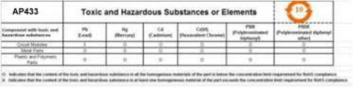
8.6 Frequencies Blocked for Regulatory Compliance
AP433e, AP433i, & AP433is are for indoor use only , in U-NII-1 and/or U-NII-3
band when Dynamic Frequency Selection, DFS, from 5.25-5.35 GHz and 5.47-
5.725 GHz, is disabled in some regions. With DFS approval from System Director
V 6.0 SR2, AP433e, AP433i, & AP433is can be operate in U-NII-2 or U-NII-2e in
some regions
OAP433e is for outdoor use only , in U-NII-1 and/or U-NII-3 band when Dynamic
Frequency Selection, DFS, from 5.25-5.35 GHz (U-NII-2) and 5.47-5.725 GHz
(UNII-2e), is disabled for some regions. With DFS approval from System Director
V6.0 SR2, OAP433e can be operated in U-NII-2 or U-NII-2e in some regions
To ensure compliance with local regulations, be sure to set your Access Point to
the country in which you are using the Access Point.
8.7 Restriction of Hazardous Substances
8.7.1 European Community
This device complies the Restriction of Hazardous Substances Directive (RoHS)
for its restriction of the use of certain hazardous substances in electrical and
electronic equipment for European Union.
8.7.2 China
This device complies Administrative Measure on the Control of Pollution Caused
by Electronic Information Products or China RoHS. 433 SERIES APe may contain
hazardous substances are marked with the EIP logo including an Environment
Friendly Use Period (EFUP) value in 10 years as Figure 43, China toxic &
hazardous substances label
Figure 43, China toxic & hazardous substances label
8.8 Underwriters Laboratories
Use only listed e information technology equipment (ITE) I.T.E. equipment.
The unit is intended for installation in Environment A as defined in IEEE 802.3.af &
802.3at.All interconnected equipments must be contained within the same building,
including the interconnected equipment's associated LAN connection.
Suitable for use in environmental air space in accordance with Section 300-22(c)
of the National Electrical Code, and Sections 2-128, 12-010(3) and 12-100 of the
Canadian Electri cal Code, Part 1, C22.1.

9 Cautions and Warnings
The cautions and warnings that appear in this manual are listed below in English,
German, French, and Spanish. Changes or modifications not expressly approved
by the party responsible for compliance could void the user’s authority to operate
the equipment.
9.1 Cautions
A Caution calls your attention to a possible hazard that can damage equipment.
"Vorsicht” weist auf die Gefahr einer möglichen Beschädigung des Gerätes in.
Une mise en garde attire votre attention sur un risque possible d'endommagement
de l'équipement. Ci-dessous, vous trouverez les mises en garde utilisées dans ce
manuel.
Un mensaje de precaución le advierte sobre un posible peligro que pueda dañar
el equipo. Las siguientes son precauciones utilizadas en este manual.
Caution!
When changing the orientation of the antennas, be sure to slightly loosen the
knurled ring before mov- ing the antenna. Retighten the ring afterward. Otherwise,
you might damage the internal cabling in the AP.
Bei einer Neuausrichtung der Antennen muss vor Bewegung der Antenne der
Rändelring leicht gelock- ert werden. Anschließend den Ring wieder festziehen.
Anderenfalls können die internen Kabel im AP beschädigt werden.
En cas de modification d’orientation des antennes, veiller à desserrer légèrement
la bague moletée avant de réorienter l’antenne. Resserrer ensuite la bague, faute
de quoi le câblage interne du point d’accès pourrait être endommagé..
Al cambiar la orientación de las antenas, asegúrese de aflojar ligeramente el anillo
estriado antes de mover la antena. Luego vuelva a apretar el anillo. De otro modo,
podría dañar el cableado interno del punto de acceso.
Caution!
The radiated output power of the access points is well below the radio frequency
exposure limits. How- ever, the Meru Access Point should be used in such a
manner that the potential for human contact during normal operation is minimized.
To avoid the possibility of exceeding the radio frequency expo- sure limits, you
should keep a distance of at least 20 cm between you (or any other person in the
vicin- ity) and the Access Point antennas.
Die abgestrahlte Ausgangsleistung von Geräten von Meru Networks, Inc. liegt weit
unter den Hochfre- quenz-Expositionsgrenzwerten der. Die Meru Access Point
Zugangspunkte von Meru Networks, Inc. sollten jedoch so verwendet werden,
dass das Potenzial für Kontakt mit Menschen während des nor- malen Betriebs
auf ein Mindestmaß beschränkt wird. Um die Möglichkeit einer Überschreitung der
- Hochfrequenz-Expositionsgrenzwerte zu vermeiden, ist ein Abstand von
mindestens 20 cm zwischen Ihnen (bzw. einer anderen Person in der Nähe) und
den Zugangspunkt-Antennen zu wahren.
La puissance de rayonnement émise par les équipements Meru Networks, Inc. est
très inférieure aux limites d'exposition aux fréquences radio définies par la.
Toutefois, les points d'accès de la série Meru Access Point de Meru Networks, Inc.
doivent être utilisés de façon à éliminer tout risque de contact humain en
fonctionnement normal. Pour éviter de dépasser les limites d'exposition aux
fréquences radio définies par la , il est impératif de préserver en permanence une
distance supérieure ou égale à 20 cm entre l'utilisateur (ou toute personne se
trouvant à proximité) et les antennes du point d'accès.
La potencia de radiación de los dispositivos de Meru Networks, Inc. está muy por
debajo de los límites de exposición a radiofrecuencia estipulados por la. No
obstante, los puntos de acceso de la serie Meru Access Point de Meru Networks,

Inc. deben usarse de tal manera que se minimice la posibilidad de contacto para
el usuario durante la operación normal. Para evitar la posibilidad de exceder los
límites de exposición a radiofrecuencia establecidos por la, el usuario (o cualquier
otra persona en torno) debe mantenerse a una distancia de al menos 20 cm
respecto a las antenas del punto de acceso.
Caution!
Exposure to Radio Frequency Radiation. The installer of this radio equipment
must ensure that the antenna is located or pointed such that it does not emit an
RF field in excess of Health Canada limits for the general population; consult
Safety Code 6, obtainable from Health Canada’s website http://www.hc-
sc.gc.ca/rpb.
Exposition aux rayonnements à fréquence radioélectrique
L'installateur de cet équipement radio doit veiller à positionner et orienter l'antenne
de telle sorte qu'elle n'émette pas un champ radioélectrique supérieur aux limites
définies par Santé Canada pour la popula- tion générale. Consulter le Code de
sécurité n° 6, disponible sur le site Web de Santé Canada à l'adresse
http://www.hc-sc.gc.ca/rpb.
Exposición a la radiación de radiofrecuencia.
El instalador de este equipo de radio debe cerciorarse de que la antena está
localizada u orientada de tal manera que no emita un campo de radiofrecuencia
superior a los límites estipulados por Health Canada para la población; consulte el
Código de Seguridad 6 que podrá encontrar en el página web de Health Canada,
http://www.hc-sc.gc.ca/rpb..
9.2 Warnings
A warning calls your attention to a possible hazard that can cause injury or death.
The following are the warnings used in this manual.
"Achtung" weist auf eine mögliche Gefährdung hin, die zu Verletzungen oder Tod
führen kön- nen. Sie finden die folgenden Warnhinweise in diesem Handbuch:
Un avertissement attire votre attention sur un risque possible de blessure ou de
décès. Ci- dessous, vous trouverez les avertissements utilisés dans ce manuel.
Una advertencia le llama la atención sobre cualquier posible peligro que pueda
ocasionar daños personales o la muerte. A continuación se dan las advertencias
utilizadas en este manual.
Warning!
With plastic covers removed, this product is suitable for use in environmental air-
handling space in accordance with the Section 300-22(c) of the National Electric
Code and Sections 2- 128.12 - 010 (3) and 12 - 100 of the Canadian Electrical
Code. Part 1. C22. 1. For other countries, consult local authori- ties for regulations.
Bei abgenommener Kunststoffabdeckung ist dieses Produkt zur Verwendung in
einem Umgebung- sluftraum gemäß Abschnitt 300-22(c) des National Electric
Code und Abschnitt 2- 128.12 - 010 (3) und 12 - 100 des Canadian Electrical
Code Teil 1. C22.1 geeignet. Die Vorschriften für andere Länder sind bei den
örtlichen Behörden erhältlich.
Sous réserve que ses couvercles de plastique soient déposés, cet appareil est
adapté à une utilisation dans les vides de construction des bâtiments selon la
section 300-22(c) du code NEC (National Electric Code) et les sections 2- 128.12 -
010 (3) et 12 - 100 du Code électrique du Canada, partie 1. C22. 1. Pour tous les
autres pays, consulter les organismes de réglementation locaux.
Una vez desprendidas las cubiertas de plástico, este producto es adecuado para
su uso en el espacio aéreo circundante en conformidad con la sección 300-22(c)
del National Electric Code (Código Eléc- trico Nacional de EE.UU.) y las
secciones 2- 128.12 - 010 (3) y 12 - 100 del Código Eléctrico de Canadá. Parte 1.
C22. 1. En otros países, consulte a las autoridades locales competentes para
infor- marse acerca de las normativas vigentes.
Warning!
Any Ethernet cables installed in air-handling spaces should be suitable under
NEC Article 800.50 and marked accordingly for use in plenums and air-handling
spaces with regard to smoke propagation, such as CL2-P, CL3-P, MPP (Multi
Purpose Plenum), or CMP (Communications Plenum).
Alle Ethernet Kabel, die in Lüftungsräumen installiert werden, sollten gemäß NEC
Artikel 800.50 geeig- net sein und entsprechend zur Verwendung in Hohlräumen
(Plenum) und Lüftungsräumen im Hinblick auf Rauchausbreitung gekennzeichnet
sein, z.B. CL2-P, CL3-P, MPP (Multi Purpose Plenum) oder CMP
(Communications Plenum).
Les câbles Ethernet installés dans un vide d’air doivent correspondre aux critères
de l’article 800.50 du code NEC et identifiés en conséquence comme adaptés à
une utilisation dans les vides de construction des bâtiments en matière de
propagation de la fumée (marquages CL2-P, CL3-P, MPP (Multi Purpose Plenum)
ou CMP (Communications Plenum)).
Todos los cables Ethernet instalados en espacios aéreos deben cumplir con el
artículo 800.50 del NEC y estar marcados adecuadamente para su uso en
espacios aéreos y plenums en lo concerniente a la propagación de humo, tales
como CL2-P, CL3-P, MPP (Plenum multifuncional), o CMP (Plenum de
comunicaciones)..
Warning!
Inside antennas must be positioned to observe minimum separation of 51 cm. (~
20 in.) from all users and bystanders. For the protection of personnel working in
the vicinity of inside (downlink) antennas, the following guidelines for minimum
distances between the human body and the antenna must be observed.The
installation of the indoor antenna must be such that, under normal conditions, all
personnel cannot come within 51 cm. (~ 20 in.) from any inside antenna.
Exceeding this minimum separation will ensure that the employee or bystander
does not receive RF-exposure beyond the Maximum Permissible Expo- sure
according to local country regulatory approval.
Innenantennen müssen so positioniert werden, dass ein Mindestabstand von 20
cm (ca. 8 Zoll) zu allen Benutzern und anderen Personen gewahrt wird. Zum
Schutz von Personal, das in der Nähe von Innenantennen (Downlink) arbeitet,
sind die folgenden Richtlinien für Mindestabstand zwischen dem menschlichen
Körper und der Antenne zu beachten.
Die Innenantenne muss so installiert werden, dass sich unter normalen
Bedingungen kein Personal bis auf weniger als 51 cm. (~ 20 Zollin.) an eine
Innenantenne annähern kann. Durch Überschreitung dieses Mindestabstands wird
sichergestellt, dass Mitarbeiter oder andere Personen keiner RF-Exposition über
die maximal zulässige Exposition (MPE; Maximum Permissible Exposure) gemäß
FCC CFR 47, Abschnitt 1.1310 (Grenzwerte für die allgemeine
Bevölkerung/unkontrollierte Exposition) ausgesetzt werden.
Les antennes intérieures doivent être positionnées de façon à respecter une
distance minimum de 51 cm par rapport aux utilisateurs et aux tiers. Pour la
protection du personnel travaillant à proximité des antennes intérieures (liaison
descendante), respecter les directives suivantes pour assurer des dis- tances
minimales entre les êtres humains et les antennes.
Toute antenne intérieure doit être installée de telle sorte que, dans des conditions
normales, le person- nel ne puisse s'en approcher à moins de 51 cm. Cette
distance minimale est destinée à garantir qu'un employé ou un tiers ne sera pas
exposé à un rayonnement radioélectrique supérieur à la valeur maxi- male
autorisée, telle qu'elle est définie dans les limites d'exposition non contrôlées pour
la population par la réglementation de la FCC CFR 47, section 1.1310.