Meru Networks AP822IV2 Dual Radio Access Point User Manual Installing AP822
Meru Networks Inc. Dual Radio Access Point Installing AP822
User Manual

Meru Networks AP822
Installation Guide
882-70018 Rev A
September 2014
Copyright © Meru Networks, Inc., 2003–2014. All rights reserved.
Other names and brands may be claimed as the property of other
iii
MERU NETWORKS, INC.
Limited Product Warranty
This Limited Product Warranty applies to the original end-user customer of the Meru product
which you purchased for your own use, and not for resale (“Product”), from Meru Networks,
Inc. (“Meru”) or its authorized reseller (“Reseller”).
Limited Warranties
•One-year limited hardware warranty: Meru warrants to you that Meru hardware (other than
Third Party Products as described below) will be free from defects in materials and work-
manship for a one-year period after the date of delivery of the applicable product to you
from Meru or its Reseller (the “Hardware Warranty Period”). If Meru receives written notice
from you of such defects during the Hardware Warranty Period, Meru will, at its option,
either repair or replace Meru hardware that Meru determines to be defective. Replacement
products may be remanufactured units, and will be warranted for the remainder of the origi-
nal Hardware Warranty Period, or if greater, for thirty days from delivery of such replace-
ment. Should Meru be unable to repair or replace the Meru hardware, Meru (or its Reseller,
as applicable) will refund to you the purchase price of the Product.
•90-Day Limited Software Warranty: Meru warrants to you that, for a 90-day period after the
date of delivery of the applicable product to you from Meru or its Reseller (the “Software
Warranty Period”), when properly installed and used, (a) the media on which the Meru soft-
ware is provided will be free from defects in materials or workmanship; and (b) the Meru
software will substantially conform to the functional specifications in the applicable docu-
mentation. If Meru receives written notice from you of a breach of this warranty during the
Software Warranty Period and is able to reproduce the defect, Meru will, at its option, either
repair or replace the defective Meru software. Should Meru be unable to repair or replace
the Meru software, Meru (or its Reseller, as applicable) will refund to you the purchase price
of the Product.
Exclusions
The warranty on the Product shall not apply to defects resulting from the following:
iv
•Alteration or modification of the Product in any way, including without limitation configura-
tion with software or components other than those supplied by Meru or integration with
parts other than those supplied by Meru.
•Abuse, damage or otherwise being subjected to problems caused by negligence or misap-
plication (including without limitation improper or inadequate maintenance or calibration),
relocation of the products (including without limitation damage caused by use of other than
Meru shipping containers), or use of the products other than as specified in the applicable
Meru product documentation (including without limitation incompatible operating environ-
ments and systems), or improper site preparation or maintenance.
•Damage as a result of accidents, extreme power surge, extreme electromagnetic field, acts
of nature or other causes beyond the control of Meru.
•Use of the Product with software, interfacing, parts or supplies not supplied by Meru.
The warranty on the Product does not apply if the Product is sold, or in the case of software,
licensed, for free for evaluation or demonstration purposes.
Meru expressly disclaims any warranty or obligation to support the Product for all operating
environments – for example, as illustration and not limitation, Meru does not warrant or ensure
interoperability of the Product with future telecommunication systems or other future software
or hardware.
You understand and acknowledge that the Products may generate, use or radiate radio fre-
quency energy and may interfere with radio communications and/or radio and television
receptions if is not used and/or installed in accordance with the documentation for such prod-
ucts. WHILE MERU USES COMMERCIALLY REASONABLE EFFORTS TO ENSURE COM-
PLIANCE OF THE PRODUCTS WITH APPLICABLE UNITED STATES FEDERAL
COMMUNICATIONS COMMISSION AND PROTECT AGAINST HARMFUL INTERFER-
ENCES, YOU ACKNOWLEDGE AND AGREE THAT INTERFERENCES WITH RADIO COM-
MUNICATIONS AND/OR RADIO AND TELEVISION RECEPTIONS MAY OCCUR AND THAT
MERU WILL NOT BE LIABLE FOR ANY DAMAGES OR INCONVENIENCE BASED ON
SUCH INTERFERENCES.
Third Party Products - The above Limited Warranties are exclusive of products manufac-
tured by third parties (“Third Party Products”). If such third party manufacturer provides a sep-
arate warranty with respect to the Third Party Product, Meru will include such warranty in the
packaging of the Meru Product.
Return procedures
To obtain warranty service you must: (a) obtain a return materials authorization number
(“RMA#”) from Meru by contacting rmaadmin@merunetworks.com, and (b) deliver the Prod-
uct, in accordance with the instructions provided by Meru, along with proof of purchase in the
form of a copy of the bill of sale including the Product’s serial number, contact information,
RMA# and detailed description of the defect, in either its original package or packaging provid-
ing the Product with a degree of protection equivalent to that of the original packaging, to Meru
v
at the address below. You agree to obtain adequate insurance to cover loss or damage to the
Product during shipment.
If you obtain an RMA# and return the defective Product as described above, Meru will pay the
cost of returning the Product to Meru. Otherwise, you agree to bear such cost, and prior to
receipt by Meru, you assume risk of any loss or damage to the Product. Meru is responsible
for the cost of return shipment to you if the Meru Product is defective.
Returned products which are found by Meru to be not defective, returned out-of-warranty or
otherwise ineligible for warranty service will be repaired or replaced at Meru’s standard
charges and shipped back to you at your expense.
At Meru’s sole option, Meru may perform repair service on the Product at your facility, and you
agree to provide Meru with all reasonable access to such facility and the Product, as required
by Meru. On-site repair service may be available and is governed by the specific terms of your
purchase.
All replaced parts, whether under warranty or not, are the property of Meru.
Warranty limitations
THE WARRANTIES SET FORTH ABOVE ARE EXCLUSIVE AND NO OTHER WARRANTY,
WHETHER WRITTEN OR ORAL, IS EXPRESSED OR IMPLIED BY MERU, TO THE MAXI-
MUM EXTENT PERMITTED BY LAW. THERE ARE NO OTHER WARRANTIES RESPECT-
ING THE PRODUCT AND DOCUMENTATION AND SERVICES PROVIDED UNDER THIS
AGREEMENT, INCLUDING WITHOUT LIMITATION ANY WARRANTY OF DESIGN, MER-
CHANTABILITY, FITNESS FOR A PARTICULAR PURPOSE (EVEN IF MERU HAS BEEN
INFORMED OF SUCH PURPOSE), TITLE OR AGAINST INFRINGEMENT OF THIRD
PARTY RIGHTS. IF ANY IMPLIED WARRANTY CANNOT BE DISCLAIMED UNDER APPLI-
CABLE LAW, THEN SUCH IMPLIED WARRANTY SHALL BE LIMITED IN DURATION TO
THE HARDWARE AND SOFTWARE WARRANTY PERIODS DESCRIBED ABOVE.
NO AGENT OF MERU IS AUTHORIZED TO ALTER OR EXCEED THE WARRANTY OBLI-
GATIONS OF MERU.
MERU SPECIFICALLY DOES NOT WARRANT THAT THE MERU SOFTWARE WILL BE
ERROR FREE OR OPERATE WITHOUT INTERRUPTION.
THE REMEDIES IN THIS LIMITED PRODUCT WARRANTY ARE YOUR SOLE AND EXCLU-
SIVE REMEDIES, AND MERU’S SOLE AND EXCLUSIVE LIABILITY, FOR BREACH OF THE
HARDWARE OR SOFTWARE WARRANTY SET FORTH ABOVE.
vi
Limitations of Liability
You acknowledge and agree that the consideration which you paid to Meru does not include
any consideration by Meru of the risk of consequential, indirect or incidental damages which
may arise in connection with your use of, or inability to use, the Product. THUS, MERU AND
ITS RESELLER WILL NOT BE LIABLE FOR ANY INDIRECT, INCIDENTAL, SPECIAL, PUNI-
TIVE OR CONSEQUENTIAL DAMAGES, INCLUDING WITHOUT LIMITATION LOST PROF-
ITS, LOST BUSINESS, LOST DATA, LOSS OF USE, OR COST OF COVER INCURRED BY
YOU ARISING OUT OF OR RELATED TO YOUR PURCHASE OR USE OF, OR INABILITY
TO USE, THIS PRODUCT OR THE SERVICES, UNDER ANY THEORY OF LIABILITY,
WHETHER IN AN ACTION IN CONTRACT, STRICT LIABILITY, TORT (INCLUDING NEGLI-
GENCE) OR OTHER LEGAL OR EQUITABLE THEORY, EVEN IF MERU OR ITS RESELLER
KNEW OR SHOULD HAVE KNOWN OF THE POSSIBILITY OF SUCH DAMAGES. IN ANY
EVENT, THE CUMULATIVE LIABILITY OF MERU OR ITS RESELLER FOR ALL CLAIMS
WHATSOEVER RELATED TO THE PRODUCT OR THE SERVICE WILL NOT EXCEED THE
PRICE YOU PAID FOR THE PRODUCT OR SERVICES GIVING RISE TO SUCH CLAIMS.
THE LIMITATIONS SET FORTH HEREIN ARE INTENDED TO LIMIT THE LIABILITY OF
MERU AND ITS RESELLERS AND SHALL APPLY NOTWITHSTANDING ANY FAILURE OF
ESSENTIAL PURPOSE OF ANY LIMITED REMEDY.
The jurisdiction applicable to you may not allow the limitations of liability or damages set forth
above, in which case such limitation shall only apply to you to the extent permitted in such
jurisdiction.
Additional Information
This Limited Product Warranty shall be governed by and construed in accordance with the
laws of the State of California, U.S.A., exclusive of its conflict of laws principles. The U.N. Con-
vention on Contracts for the International Sale of Goods shall not apply.
This Limited Product Warranty is the entire and exclusive agreement between you and Meru
with respect to its subject matter, and any modification or waiver of any provision of this state-
ment is not effective unless expressly set forth in writing by an authorized representative of
Meru.
All inquiries or claims made under this Limited Product Warranty must be sent to Meru at the
following address:
Meru Networks Inc.,
894 Ross Drive, CA 94087, USA
Tel: 408-215-5300
Fax: 408-215-5301
Email: support@merunetworks.com
Table of Contents vii
About AP822 . . . . . . . . . . . . . . . . . . . . . . . . . . . . . . . . . . . .11
Features . . . . . . . . . . . . . . . . . . . . . . . . . . . . . . . . . . . . . . . . . . . 12
IEEE Std 802.11ac in AP822 . . . . . . . . . . . . . . . . . . . . . . . . . . . 12
Installation Location . . . . . . . . . . . . . . . . . . . . . . . . . . . . . . . . . . 13
Safety Precautions . . . . . . . . . . . . . . . . . . . . . . . . . . . . . . . . . . . 13
Installing AP822eV2 . . . . . . . . . . . . . . . . . . . . . . . . . . . . . .15
Before You Begin . . . . . . . . . . . . . . . . . . . . . . . . . . . . . . . . . . . . 15
Package Contents . . . . . . . . . . . . . . . . . . . . . . . . . . . . . . . . . . . . . . . . . . . 15
Kensington Lock . . . . . . . . . . . . . . . . . . . . . . . . . . . . . . . . . . . . . . . . . . . . 16
Power Options . . . . . . . . . . . . . . . . . . . . . . . . . . . . . . . . . . . . . . . . . . . . . . 16
AP822eV2 Antennas. . . . . . . . . . . . . . . . . . . . . . . . . . . . . . . . . . 17
Radio-Antenna-Port Mappings . . . . . . . . . . . . . . . . . . . . . . . . . . . . . . . . . 17
Attaching Antennas . . . . . . . . . . . . . . . . . . . . . . . . . . . . . . . . . . . . . . . . . . 17
Installing AP822iV2 . . . . . . . . . . . . . . . . . . . . . . . . . . . . . . .19
Before You Begin . . . . . . . . . . . . . . . . . . . . . . . . . . . . . . . . . . . . 19
Package Contents . . . . . . . . . . . . . . . . . . . . . . . . . . . . . . . . . . . . . . . . . . . 19
Kensington Lock . . . . . . . . . . . . . . . . . . . . . . . . . . . . . . . . . . . . . . . . . . . . 19
Power Options . . . . . . . . . . . . . . . . . . . . . . . . . . . . . . . . . . . . . . . . . . . . . . 20
Table of Contents
Table of Contentsviii
AP822 Mounting . . . . . . . . . . . . . . . . . . . . . . . . . . . . . . . . .21
Horizontally on a Shelf. . . . . . . . . . . . . . . . . . . . . . . . . . . . . . . . . . . . . . . . 21
Vertically on a Wall . . . . . . . . . . . . . . . . . . . . . . . . . . . . . . . . . . . . . . . . . . 22
Box Mount . . . . . . . . . . . . . . . . . . . . . . . . . . . . . . . . . . . . . . . . . . . . . . . . . 26
Below a Standard Suspended Ceiling . . . . . . . . . . . . . . . . . . . . . . . . . . . . 27
Above a Standard Suspended Ceiling. . . . . . . . . . . . . . . . . . . . . . . . . . . . 33
LED Lights. . . . . . . . . . . . . . . . . . . . . . . . . . . . . . . . . . . . . . . . . . 35
LED Activity and Meaning . . . . . . . . . . . . . . . . . . . . . . . . . . . . . . . . . . . . . 37
Changing LED Appearance. . . . . . . . . . . . . . . . . . . . . . . . . . . . . . . . . . . . 37
Next Steps. . . . . . . . . . . . . . . . . . . . . . . . . . . . . . . . . . . . . . . . . . 38
Approved Antennas. . . . . . . . . . . . . . . . . . . . . . . . . . . . . . .39
Wall Mount AP832e Antenna Orientation . . . . . . . . . . . . . . . . . . 39
Option 1Vertical Antenna Orientation (90 degrees to AP). . . . . . . . . . . . . 40
Option 2 Horizontal Antenna Orientation. . . . . . . . . . . . . . . . . . . . . . . . . . 41
Regulatory Information........................................................43
Regulatory Specifications . . . . . . . . . . . . . . . . . . . . . . . . . . . . . . 44
Declaration of Conformity, Federal Communication Commission 44
Manufacturer Information. . . . . . . . . . . . . . . . . . . . . . . . . . . . . . . . . . . . . . 44
Declaration of Conformity . . . . . . . . . . . . . . . . . . . . . . . . . . . . . . . . . . . . . 45
Declaration of Conformity, Industry Canada . . . . . . . . . . . . . . . . 45
Manufacturer Information. . . . . . . . . . . . . . . . . . . . . . . . . . . . . . . . . . . . . . 46
Declaration of Conformity . . . . . . . . . . . . . . . . . . . . . . . . . . . . . . . . . . . . . 46
Declaration of Conformity, R&TTE Directive 1999/5/EC. . . . . . . 48
Declaration of Conformity . . . . . . . . . . . . . . . . . . . . . . . . . . . . . . . . . . . . . 48
Table of Contents ix
VCCI Statement . . . . . . . . . . . . . . . . . . . . . . . . . . . . . . . . . . . . . 51
General Information of RF Exposure . . . . . . . . . . . . . . . . . . . . . 51
International Guidelines. . . . . . . . . . . . . . . . . . . . . . . . . . . . . . . . . . . . . . . 51
FCC Guidelines . . . . . . . . . . . . . . . . . . . . . . . . . . . . . . . . . . . . . . . . . . . . . 52
Industry Canada Guidelines . . . . . . . . . . . . . . . . . . . . . . . . . . . . . . . . . . . 53
Additional Notes ..................................................................55
Maximum EIRP . . . . . . . . . . . . . . . . . . . . . . . . . . . . . . . . . . . . . . 55
Dual Concurrent Same Band Operation . . . . . . . . . . . . . . . . . . . 55
Manufacturing Information . . . . . . . . . . . . . . . . . . . . . . . . . . . . . 55
Distributed Antenna Systems (DAS). . . . . . . . . . . . . . . . . . . . . . 55
Air Handling Space Requirements . . . . . . . . . . . . . . . . . . . . . . . 56
Frequencies Blocked for Regulatory Compliance. . . . . . . . . . . . 56
Underwriters Laboratories . . . . . . . . . . . . . . . . . . . . . . . . . . . . . . . . . . . . . 56
Restriction of Hazardous Substances. . . . . . . . . . . . . . . . . . . . . 57
European Community . . . . . . . . . . . . . . . . . . . . . . . . . . . . . . . . . . . . . . . . 57
China . . . . . . . . . . . . . . . . . . . . . . . . . . . . . . . . . . . . . . . . . . . . . . . . . . . . . 57
Cautions and Warnings.......................................................59
Cautions . . . . . . . . . . . . . . . . . . . . . . . . . . . . . . . . . . . . . . . . . . . 59
Warnings. . . . . . . . . . . . . . . . . . . . . . . . . . . . . . . . . . . . . . . . . . . 61
Table of Contentsx

11
1About AP822
The AP822 is a cost-effective, dual-radio, 802.11a/b/g/n/ac WLAN access point with a 2x2:2ss
design. It can operate in the 2.4 GHz band for 802.11n support and in the 5 GHz band for
802.11ac to deliver an aggregate data rate of 1.2 Gbps for demanding business applications
such as video and voice. The access point is offered with a choice of internal or external
antenna models. Learn more.
AP822 is available in two models AP822iV2 and AP822eV2.
Features12
Features
IEEE Std 802.11ac in AP822
The AP822 series is the first of Meru access point family capable of operating in the IEEE Std
802.11ac mode, which is capable for theoretical throughput rates up to 866 Mbps per radio.
IEEE Std 802.11ac is applied only on the 5 GHz band, and its higher throughput levels require
the use of 80 MHz wide channels.
When a radio on AP822 is configured for IEEE Std 802.11ac operation, it is automatically set
to operate on the 5 GHz band. By default, the radio 1 is set to operate on the 2.4 GHz band
(Channel 6, 20 MHz channel width) to support IEEE Std 802.11b/g/n clients and radio 2 is con-
figured for IEEE Std 802.11ac on 5 GHz (Primary Channel 36 with 80 MHz channel width).
With backward compatibility, AP822’s Radio 2 supports either IEEE 802.11a or IEEE 802.11a/
n clients.
TABLE 1: AP822 Feature List
AP822iV2 AP822eV2
Two dual-band-selectable radios, in either
2.4 GHz or 5.x GHz, capable of operating
in IEEE 802.11b/g/a/n and IEEE 802.11ac
DRAFT standards, with INTERNAL anten-
nas.
Two dual-band-selectable radios, in either
2.4 GHz or 5.x GHz, capable of operating
in IEEE 802.11b/g/a/n and IEEE 802.11ac
DRAFT standards, with optional EXTER-
NAL antennas.
Supported by System Director versions 6.1 and greater.
Supports 80-MHz channel-bonding (VHT80) in 5.x GHz band with IEEE Std 802.11ac. 80-
MHz channel-bonding (VHT80) combines four 20-MHz channels into a single 80-MHz
channels for increasing bandwidth.
Supports Plug and Play deployment.
Supports multi-layered security including Enterprise WPA2 features such as automatic
traffic inspection.
Powered by either a standard IEEE 802.3af or IEEE 802.3at PoE switches or PoE injec-
tors. Supports an optional 12v external power adapter.
Supports channel span architecture that requires no channel planning or configuration.
Supports wired stations via the secondary Ethernet interface.
Provides pre-pack PHY data rate up to 866 Mbps per radio at IEEE Std 802.11ac with
MCS9/QAM-256 mode.

Installation Location 13
Installation Location
All AP822 interconnected equipment must be contained within the same building, including
the interconnected equipment's associated LAN connection. Ceiling mount is recommended
but wall mount is also supported. In addition, the AP822 should be mounted in a location that
meets the following conditions:
•Unobstructed access to stations - relatively unobstructed access to the stations the AP
serves. Select a location with minimal physical obstructions between the AP and the wire-
less stations. In an office with cubicles, mounting the APs below a hanging ceiling or the
wall near the ceiling provides the least obstructed communications path. On a wall, orient
the AP822 horizontally so that you can read the Meru logo without tilting your head at 90
degrees - this orientation provides optimum MIMO performance.
•Access to power - access to wall outlet or to a Power over Ethernet (PoE) connection to
the network switch servicing the controller.
•Capacity Planning - AP822 is capable of associating up to 128 clients per radio or 256 cli-
ents per system. For optimum performance, Meru Networks recommend planning up to 50
clients per radio for a mixed WLAN voice, video, and data. Users can, however, achieve
higher client capacity in a data traffic only environment. Refer to the Meru Deployment
Guides on the support site for more information.
•Install APs toward the center of the building.
•Place APs about 80 feet apart.
•Do not install APs near metal objects, such as heating ducts, metal doors, or electric ser-
vice panels.
•If you install an AP822 on a pole, its coverage will be a half spherical shape. Mounting two
AP822’s (back to back) on a poll does not provide full coverage (spherical shape). This
could potentially interfere with each other resulting in poor coverage.
Safety Precautions
IMPORTANT—Read and follow the regulatory instructions in Appendix B before installing and
operating this product.
If an optional power supply is used, it must be one supplied by Meru Networks.
With grant of additional regulatory approvals and Permit-but-Ask by US Federal Communication Com-
mission, users can configure two radios in AP822 on the same band (i.e., both radios are on the 2.4
GHz but in the different or same channels, or both radios are on the 5.x GHz but in the different or
same channels). However, user shall expect performance deterioration due to RF collision. collocation,
or co-channel interference (CCI). It is important that the users reduce AP822 transmit power, for each
radio, by at-least 3 dBm for its default setting. It is also recommended to apply such use case in
AP822eV2 with pigtail attached external antennas only.

Safety Precautions14
The AP822 is intended only for installation in Environment A as defined in IEEE Std 802.3af.
All interconnected equipment must be contained within the same building, including the inter-
connected equipment's associated LAN connection.
This product is intended to be supplied by a UL Listed power supply marked Class 2 or LPS and rated
12Vdc, 2A. For Power over Ethernet, an 802.3af or 802.3at connection must be used.

Before You Begin 15
2Installing AP822eV2
This chapter provides all the information that users need to install Meru AP822eV2. After user
completing installation procedure, see the Meru System Director 6.1 Configuration guide for
detailed instructions on the various configuration options.
Follow all safety precautions mentioned in the “Safety Precautions” on page 13 section.
Before You Begin
This section provides information that users should know before installing AP822eV2.
Package Contents
The AP822eV2 shipping package should contain the following. Please contact Meru, if pack-
ages do not contain any of the following items.
TABLE 1: Package Contents
Item Model Number Quantity
AP822 AP822eV2 1
Omni Directional Rubber Duck antenna ANT-01ABGN-0303-0
Gain: 3/4 dBi
4
15/16” T-Bar & Wall-mount combo adapter
(650-00232)
1
9/16” T-bar Adapter (650-00233) 1
Wall-mount bracket (650-00234) 1
Wall-mount hardware kit (4 spacers,
M3x10 & M3x30 screws) (840-00126)
1
Before You Begin16
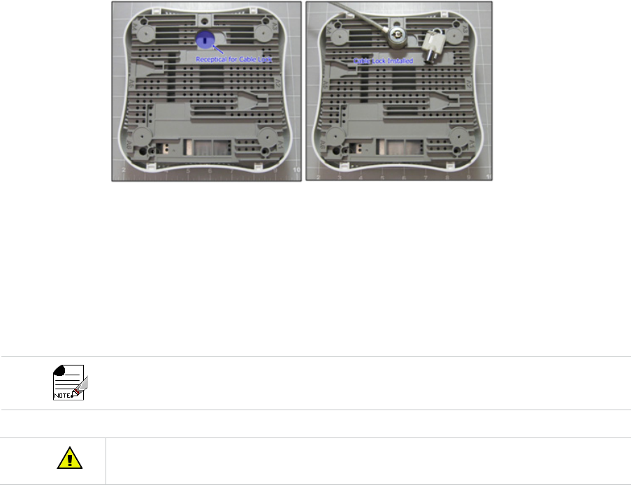
Kensington Lock
The AP822eV2 has an access slot at the back to support Kensington Lock. Users can lock the
AP822eV2 with a standard security cable, such as those used to secure laptop computers.
See “AP822 Kensington lock” on page 16 for location of AP822 Kensington Lock.
Figure 1: AP822 Kensington lock
Power Options
A power source is needed to power the AP822eV2. The AP822eV2 requires either IEEE Std
802.3af or IEEE Std 802.3at compatible external Power-over-Ethernet (PoE) switch or PoE
injector. If the PoE power source is not available, a 12-V DC power (2A rated) must be sup-
plied.
When connected to an IEEE Std 802.3af PoE power source, both the USB and the secondary Ethernet
port (G2) shall be disabled due to power limitations.
AP822 is intended to be supplied by a UL listed power supply marked Class 2 or LPS and rated 12Vdc,
2A. If an optional power supply is used, it must be one supplied by Meru Networks.

AP822eV2 Antennas 17
AP822eV2 Antennas
Radio-Antenna-Port Mappings
The following table lists which radio is associated with each antenna.
Attaching Antennas
An AP822eV2 has four external antenna ports, labeled A1, A3, A4 and A6, to be used for
attaching the antennas supplied with the AP. Do not leave any antenna connector open. All
connectors on the AP must be terminated either with antennas or with 50 ohm Reverse Polar-
ity SMA terminators. For a list of approved terminators, see http://www.merunetworks.com/
merusupport.
Antennas attached to a specific radio in AP822eV2 must all be of the same model. In case of
replacement, user must replace all the antennas.
TABLE 2: Radio-Antenna-Port Mappings
Antenna Port Radio / Channel
A1 Radio 1
A3 Radio 1
A4 Radio 2
A6 Radio 2
AP822eV2 Antennas18

Before You Begin 19
3Installing AP822iV2
This chapter provides all the information that users need to install Meru AP822iV2. After user
completing installation procedure, see the Meru System Director 6.1 Configuration guide for
detailed instructions on the various configuration options.
Follow all safety precautions mentioned in the “Safety Precautions” on page 13 section.
Before You Begin
This section provides information that users should know before installing AP822iV2.
Package Contents
The AP822iV2 shipping package should contain the following. Please contact Meru, if pack-
ages do not contain any of the following items.
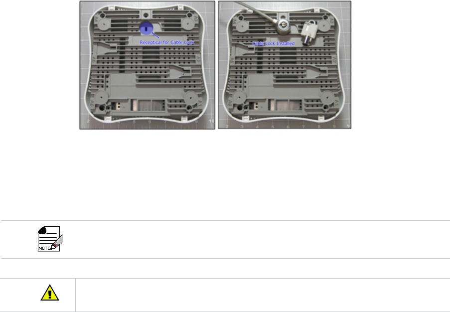
Kensington Lock
The AP822iV2 has an access slot at the back to support Kensington Lock. Users can lock the
AP822iV2 with a standard security cable, such as those used to secure laptop computers. See
“AP822 Kensington lock” on page 20 for location of AP822 Kensington Lock.
TABLE 3: Package Contents
Item Model Number Quantity
AP822 AP822iV2 1
15/16” T-Bar & Wall-mount combo adapter
(650-00232)
1
9/16” T-bar Adapter (650-00233) 1
Wall-mount bracket (650-00234) 1
Wall-mount hardware kit (4 spacers,
M3x10 & M3x30 screws) (840-00126)
1
Before You Begin20
Figure 2: AP822 Kensington lock
Power Options
A power source is needed to power the AP822iV2. The AP822iV2 requires either IEEE Std
802.3af or IEEE Std 802.3at compatible external Power-over-Ethernet (PoE) switch or PoE
injector. If PoE power source is not available, 12-V DC power (2A rated) must be supplied.
When connected to an IEEE Std 802.3af PoE power source, both USB and the secondary Ethernet
port (G2) shall be disabled due to power limitations.
AP822iV2 is intended to be supplied by a UL listed power supply marked Class 2 or LPS and rated
12Vdc, 2A. If an optional power supply is used, it must be one supplied by Meru Networks.

21
4AP822 Mounting
AP822 ships with several different mounting bracket components that allow for a variety of
mounting options. You can mount an AP822 in any of the following ways:
You can mount an AP822 in any of the following ways:
•“Horizontally on a Shelf” on page 21
•“Vertically on a Wall” on page 22
•“Box Mount” on page 26
•“Below a Standard Suspended Ceiling” on page 27
•“Above a Standard Suspended Ceiling” on page 33
Horizontally on a Shelf
When mounting an AP822 horizontally, place it on the desired surface and connect the power
and network cables (G1 Ethernet Port is also used a PoE input). Optional stands (MNT-FEET-
SET-X5) can be applied underneath to raise AP822 for additional cabling space.
Read and follow the regulatory instructions in Appendix A before installing and operating AP822.

22
The accessory required for such installation is listed below:
Vertically on a Wall
Installation
The AP822 ships with a metal bracket (650-00234) that can be used for wall mounting. This
bracket is used in conjunction with the plastic 15/16” T-Bar Adapter/Wall Mount bracket (650-
00232) that easily locks the AP into place.
The accessory required for such installation is listed below:
1. User should bench test this mounting hardware in order to familiarize with the locking
mechanism prior to actual installation.
2. Determine the desired location for mounting.
3. Use the wall mount bracket as a template for screw holes and cable cutout.
•User may need to cut a hole in the wall or ceiling in the cable cutout area in order to hide
the cables during installation.
•User may also use the optional RJ45 cable extension (840-00124 CBL-RJ45-ADAPT-X5,
comes in a 5 pack), if user do not want to cut a hole in the wall or ceiling.
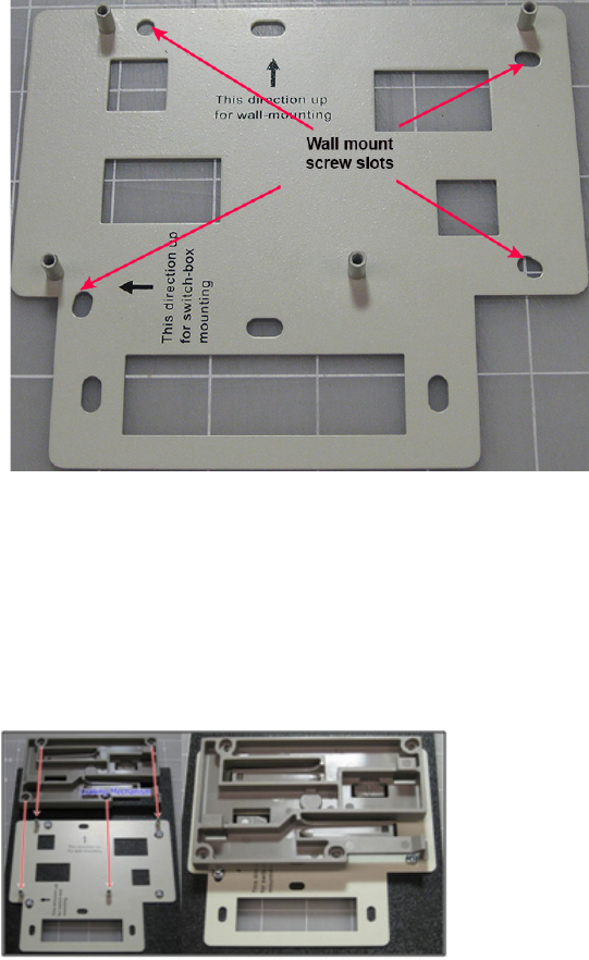
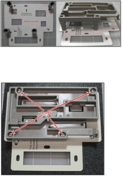
4. Place the metal bracket against the wall. It should be oriented such that the indicator text
for wall-mounting is pointing upwards.
5. Attach the bracket to the wall using screws at the appropriate screw locations as indicated
in “AP822 Wall Bracket” on page 23. Recommend #6, #8 (M3, M3.5).
Item Model Number Quantity
Stands (Optional) MNT-FEET-SET-X5 1 (set)
Item Model Number Quantity
15/16" T-bar & wall-mount combo
adapter (650-00232)
1
Wall-mount bracket (650-00234) 1
Wall-mount hardware kit (4 spac-
ers, M3x10 & M3x30 screws)
(840-00126)
1
23
Figure 3: AP822 Wall Bracket
6. Orient 15/16" T-Bar adapter/Wall mount adapter to line up with posts on wall mount
bracket.
7. AP locking mechanism should be facing away from bracket.
8. Position the adapter over posts on wall mount bracket.
•User may mount the wall mount adapter directly to the wall mount bracket or use the
included option spacers to allow additional clearance between the AP and bracket. See
“AP822 Wall Bracket without spacers” on page 23 and “AP822 Wall Bracket with spacers”
on page 24.
Figure 4: AP822 Wall Bracket without spacers
24
Figure 5: AP822 Wall Bracket with spacers
9. Secure the adapter to the wall mount bracket with the screws provided:
•Use the 4 short screws for installation without spacers
•Use the 4 long screws for installation with spacers
Figure 6: AP822 adapter to the wall mount bracket
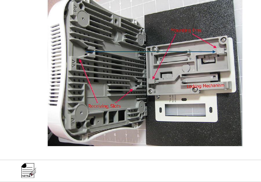
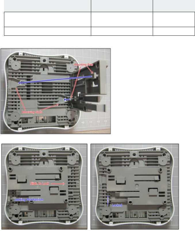
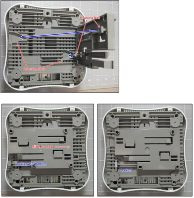
10.Orient the AP so that the 2 mounting pins align with the receiving slots.
25
Figure 7: Attaching the AP to the Wall Mount
11.The Meru logo on the front of the AP should face up and be readable. The ports on the AP
should be in line with the cable cutout on the wall mount bracket.
12.Make any necessary cable connections at this time (Ethernet, power, locking cable).
13.Carefully position the AP over the adapter bracket pins and slide the AP gently from left to
right until the locking mechanism “clicks” into place. Verify that the locking mechanism is
securely locked into place to prevent accidental disengagement and potential damage, if
dropped.
14.Verify that the AP comes online.
Figure 5 shows an AP822iV2 model being attached to the bracket, but the process is identical for either
AP.
26
Figure 8: Successful installation (with optional spacers)
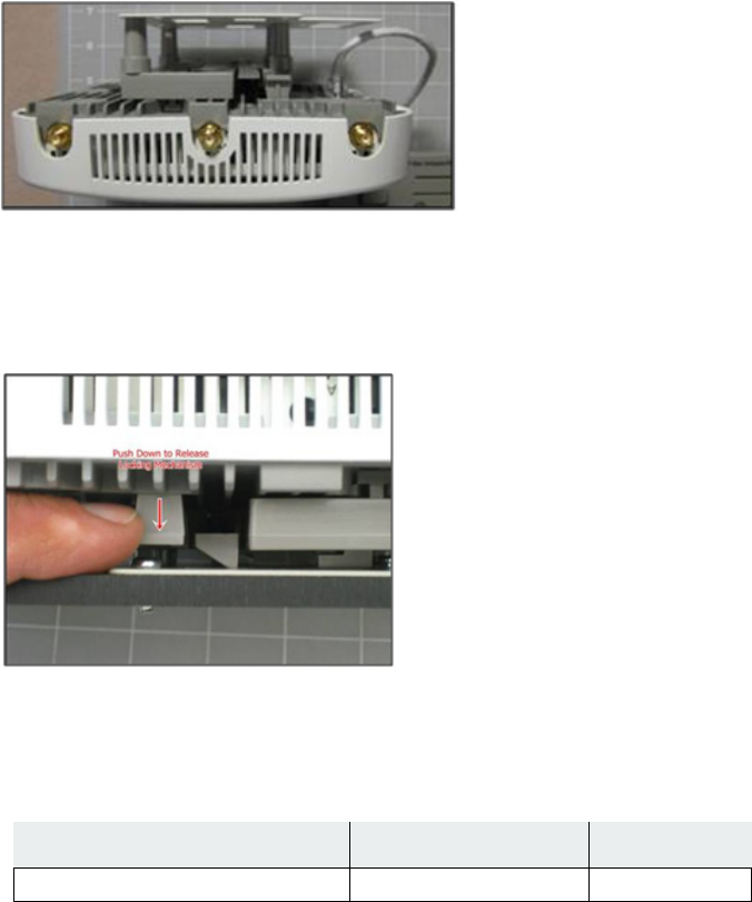
Removal
To remove the AP from the wall mount, depress the locking mechanism tab toward the wall
and slide the AP from right to left until it releases.
Figure 9: AP822 removal
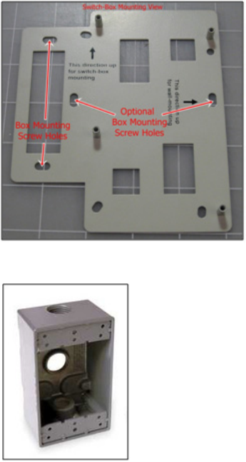
Box Mount
The accessory required for such installation is listed below:
1. Orient the wall mount bracket with the arrow up for box mount.
Item Model Number Quantity
Wall-mount bracket (650-00234) 1
27
Figure 10: AP822 Box Mounting Screws
2. Use the desired holes as indicated in the “AP822 Box Mounting Screws” on page 27 to
mount bracket to the box.
3. Follow the wall mount installation instructions as appropriate.
Below a Standard Suspended Ceiling
The provided ceiling mounting brackets allow the AP822 to attach to suspended ceiling T-rails.
The AP ships with two different ceiling mounting bracket options to accommodate varying
sizes of ceiling T-rails. Be sure to attach the correctly-sized bracket to your AP prior to
attempting to deploy it. Note that each plastic bracket contains descriptive text to indicate the
ceiling T-rail size for which it is designed.
28
AP Installation over Standard 9/16” or 15/16” T-Bar
The accessory required for such installation is listed below:
1. Orient T-Bar adapter/Wall mount adapter with the back of the AP, so that the 2 mounting
pins align with the receiving slots.
2. Slide the adapter plate from left to right until the locking mechanism “clicks” into place.
Item Model Number Quantity
15/16” T-bar & wall-mount combo
adapter (650-00232)
1
9/16” T-bar adapter (650-00233) 1
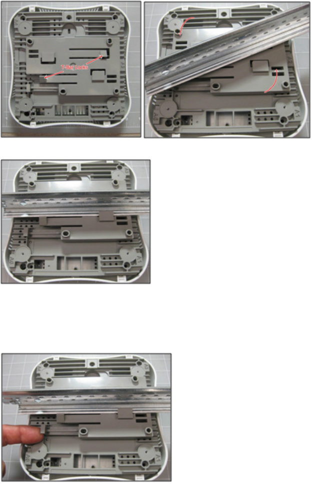
29
3. Position the AP up to the T-Bar at an angle and depress slightly to disengage T-Bar locks.
4. Twist the AP clockwise to engage T-Bar locks. There should be 2 audible clicks.
5. Verify that the AP comes online.
AP Removal from Standard 9/16” or 15/16” T-Bar
1. To remove the AP from ceiling, release the locking mechanism by pressing tab up,
towards the ceiling and slide the AP from right to left until it releases.
30
2. To remove the 15/16" T-Bar adapter/Wall mount adapter from the T-Bar, depress both T-
Bar locks at the same time and twist counter-clockwise to release.
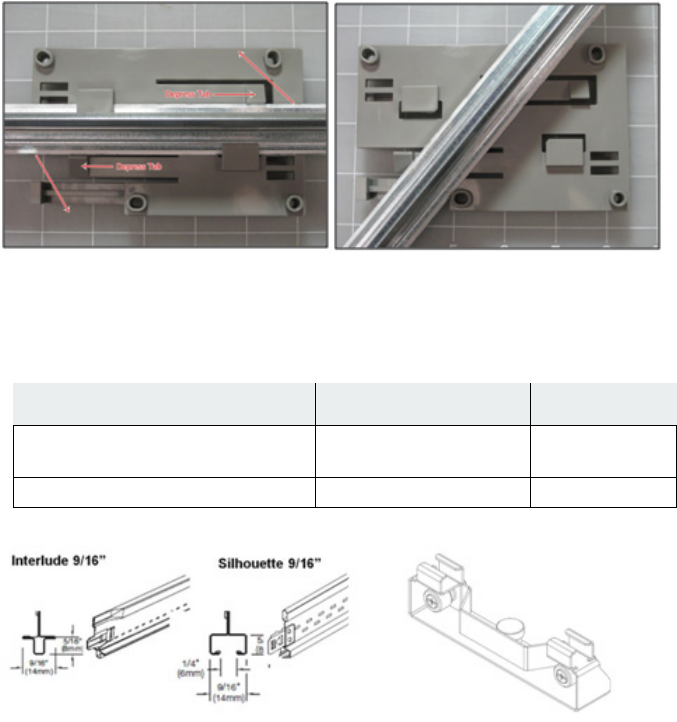
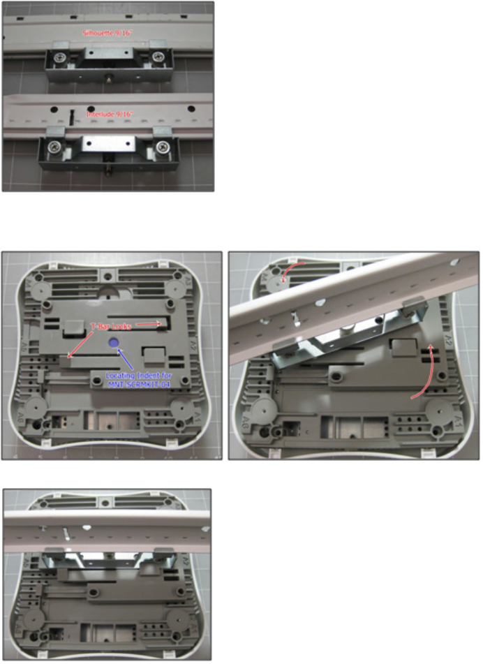
AP Installation over Interlude & Silhouette T-Bars
The accessory required for such installation is listed below:
Item Model Number Quantity
15/16” T-bar & wall-mount combo
adapter (650-00232)
1
T-bar Adapter (Optional) MNT-SCRMKIT-04 1
31
1. Orient T-Bar adapter/Wall mount adapter with the back of the AP, so that the 2 mounting
pins align with the receiving slots.
2. Slide the adapter plate from left to right until the locking mechanism “clicks” into place.
32
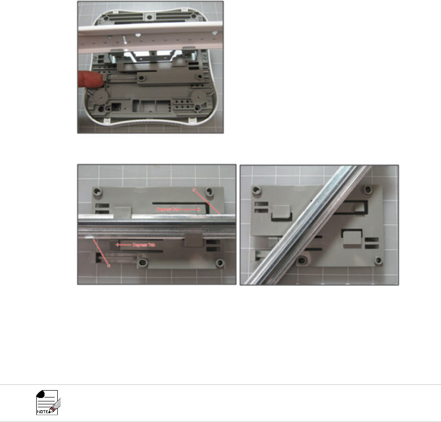
3. Install the optional accessory “MNT-SCRMKIT-04” to T-Bar. This is accomplished by loos-
ening the two clamp screws, positioning the clamps over the T-Bar and re-tightening the
screws until secure.
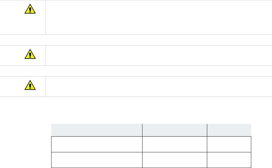
4. Position the AP with the adapter plate installed, up to the T-Bar with the “MNT-SCRMKIT-
04” installed, at an angle. Be sure that the locating pin on the “MNT-SCRMKIT-04” is posi-
tioned in the indent on the adapter. Depress slightly to disengage T-Bar locks.
5. Twist the AP clockwise to engage T-Bar locks. There should be 2 audible clicks.
33
6. Verify that the AP comes online.
AP Removal from Interlude & Silhouette T-Bar
1. To remove the AP from ceiling, release the locking mechanism by pressing tab up, toward
the ceiling and slide the AP from right to left until it releases.
2. To remove the 15/16” T-Bar adapter/Wall mount adapter from the T-Bar, depress both T-
Bar locks at the same time and twist counter-clockwise to release.
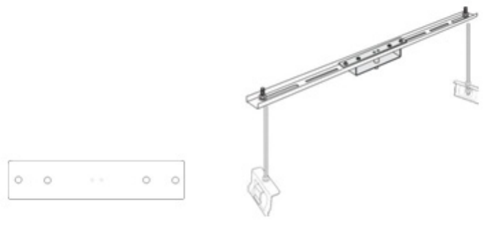
Above a Standard Suspended Ceiling
By removing plastic facade, AP822eV2 can be installed in air-handling space. Use the
optional T-bar box hanger mounting kit to mount AP822eV2 above suspended ceiling T- rails.
The installation attaches the T-bar box hanger to the ceiling rails and then the AP822eV2
attaches to the T-bar box hanger.
AP822eV2 mounted above the ceiling has about 2-3 dBm less RF coverage than
AP822eV2 mounted under the ceiling.
34
The accessory required for such installation is listed below:
1. Determine the location on the ceiling rails where the AP will be mounted and remove the
ceiling tile.
2. Unpack the T-bar hanger kit.
3. Attach the mounting bar (depicted in Figure 8) to the mounting brace (which looks like a
small handle) with the crossbar of the mounting kit sandwiched between them
4. Locate the 650-00232 15/16" T-Bar Adapter/Wall Mount and attach the AP to the mount-
ing bracket by pressing the bracket's Mounting Pins (shown in Figure 2 on page 9) to the
AP's Receiving Slots and sliding the bracket until it locks in place.
5. Gently press the underside of the AP against the mounting brace and rotate it into place
until the locking mechanism clicks.
6. Attach the legs for the mounting kit to the T-Bars in the ceiling by sliding the clips down
onto each respective bar.Remove the top nut from each leg.
7. Lower the crossbar (with the AP attached) onto the legs and screw the nuts back on top of
the bar.
8. Connect one end of the PoE Ethernet cable to the Ethernet connector on the AP.
9. Connect one end of the CAT5 (or greater) Ethernet cable with PoE to the 100/1000 Ether-
net connector on the underside of the AP.
The AP822eV2 with plastic cover removed is suitable for use in environmental air-handling space
above a suspended ceiling in accordance with the Section 300-22(c) of the National Electric Code and
Sections 2- 128.12 - 010 (3) and 12 - 100 of the Canadian Electrical Code. Part 1. C22. 1. Note that in
order to comply with these standards, the plastic cover on the AP822eV2 must be removed.
Users shall only apply certified external antennas with plenum-rated cables in this installation.
When installed in air-handling spaces, such as above a suspended ceiling, power the AP822eV2 only
with a PoE not a power supply.
You may need to use thicker tiles to support this installation.
Item Model Number Quantity
15/16” T-bar & wall-mount combo
adapter (650-00232)
1
T-bar hanger (Optional)
(840-00071)
ACC-MTN-ASCMKIT 1
LED Lights 35
10.Check that the AP822eV2 is operating correctly before replacing the ceiling tile to the ceil-
ing. It can also be installed with the AP822eV2 on top by flipping cross bar. Verify correct
operation using the LEDs, as shown in “LED Activity and Meaning” on page 37.
LED Lights
When AP822 first connects to the controller (and any time the access point is rebooted), the
AP initializes and then is programmed by the controller. When the AP first powers up, the LED
is green. Thereafter, its color indicates its operating status.
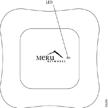
LED Lights36
Figure 11: AP822 Status LED
After the AP822 is connected, check the status of the LED. Its indicator state is described
below.
LED Lights 37
LED Activity and Meaning
Changing LED Appearance
If user wants to change the appearance of the LEDS, follow these steps:
1. From the controller, click Configuration > Devices > AP, and then select the AP.
2. Select one of these settings for the LED Mode setting:
•Normal: LEDs are as described above
•Blink: Sets all LEDs flashing; this is useful to locate an AP
•Dark: Turns off all LEDs
3. Click OK.
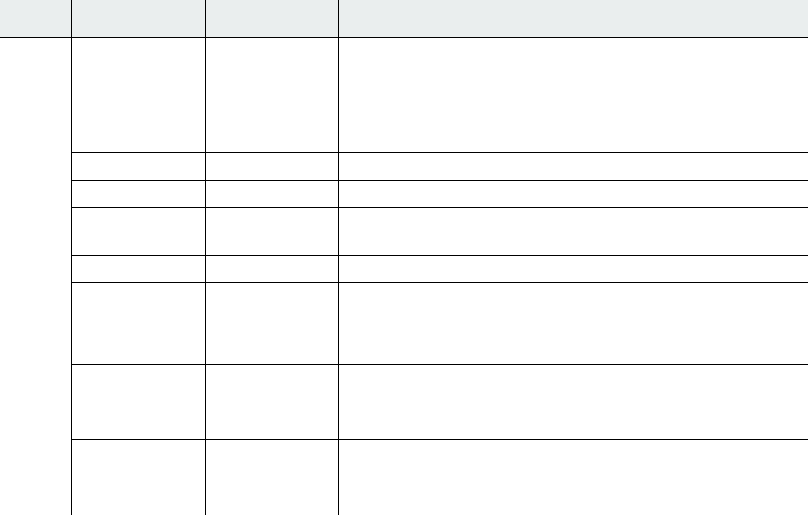
TABLE 4: LED Activity and Meaning
LED COLOR STATE MEANING
Status No Color — No power.
Either there is no power or the LEDs are set to Off on the con-
troller. Check the LED setting on the controller by clicking
Configuration > Devices > AP, selecting the AP and then
checking the setting for LED Mode.
CYAN ON AP starting, stage 1.
GREEN Blinking AP starting, stage 2.
GREEN/
WHITE
Alternating AP is discovering the controller.
GREEN/BLUE Alternating AP is downloading configuration from the controller.
BLUE Blinking slowly AP is online and enabled.
BLUE Blinking rapidly AP is online and enabled.
Some activity on one or both radios.
RED/YELLOW Alternating AP Failure.
For details, check the controller for alarms by clicking Monitor
> Alarms > Pending Alarms.
BLUE/YEL-
LOW
Alternating AP is online and enabled.
One or both radios are either scanning or an admin has shut-
down the radios.
Next Steps38
Next Steps
Now that the AP822 is installed, see the Meru System Director Getting Started Guide for
instructions on initializing the hardware. Return to this chapter to check the status of the LEDs
once the WLAN is operational.

Wall Mount AP832e Antenna Orientation 39
5Approved Antennas
Only approved antennas may be used in conjunction with AP822eV2 access points. Access
Points have been designed to operate with the antennas listed below. Antennas not included
in this list are strictly prohibited for use with these devices. The required antenna impedance
is 50 ohms.
Wall Mount AP832e Antenna Orientation
There are 2 recommended options for wall mount antenna orientations.
TABLE 5: Approved Antennas
Meru Part Numbers Gain Description
ANT-ABGN23O-W 2/3 dBi Dual band Omni-directional dipole antenna
ANT-ABGN47O 4.7/4.7 dBi Dual band high gain dipole Omni directional
antenna
ANT-O4ABGN-0606-O 6/6 dBi Dual band Omni directional 4-lead antenna
ANT-I2ABGN-0304-O 3/4 dBi Dual band ceiling mount Omni directional 2-
lead antenna
ANT-O4ABGN-0607-
PT
6/7 dBi Dual band wall mount patch 4-lead antenna
ANT-ABGN-0406-W 4/6dBi Dual band Omni-directional antenna single
feed
Wall Mount AP832e Antenna Orientation40
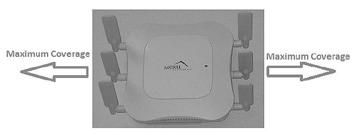
Option 1Vertical Antenna Orientation (90 degrees to AP)
Figure 12: Vertical Antenna Orientation
Option 1 is recommended where the maximum coverage is required towards the sides of the
AP and the minimum coverage in front of the AP as shown in Figure 1. Example: Mounting the
AP at the middle of the corridor wall where the maximum coverage is required on both sides of
the AP.
Wall Mount AP832e Antenna Orientation 41
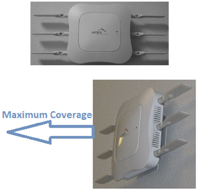
Option 2 Horizontal Antenna Orientation
Figure 13: Horizontal Antenna Orientation
Figure 14: Horizonta Antenna Orientation (Side View)
Option 2, horizontal antenna orientation is recommended where the maximum coverage is
required in front of the AP and the minimum coverage is required towards the sides of the AP
as shown in Figure 3.
Example: Mounting the AP on the end wall of the corridor where the maximum coverage is
required in front of the AP.
Wall Mount AP832e Antenna Orientation42

43
ARegulatory Information
The Meru Access Point (APs) must be installed and used in strict accordance with the manu-
facturer’s instructions as described in the user documentation that comes with the product.
For country-specific approvals, see below. Meru Networks, Inc. is not responsible for any
radio or television interference caused by unauthorized modification of APs, or the substitu-
tion or attachment of connecting cables and equipment other than that specified by Meru Net-
works, Inc. The correction of interference caused by such unauthorized modification,
substitution or attachment is the responsibility of the user. Meru Networks, Inc. and its autho-
rized resellers or distributors are not liable for any damage or violation of government regula-
tions that may arise from the user failing to comply with these guidelines.

Regulatory Specifications44
Regulatory Specifications
Declaration of Conformity, Federal
Communication Commission
Manufacturer Information
Meru Networks, Inc
894 Ross drive,
Sunnyvale, CA 94089
USA
TABLE 6: Regulatory Specifications
Category Items
Safety •UL 60950-1
•CSA C22.2
•EN 60950-1
•IEC 60950-1
Unintentional Radiation Compliance •FCC Part 15.107 - 47CFR15.107
•FCC Part 15.109 - 47CFR15.109 B
•ICES-003 Class B
•EN 301 489-1
•EN 301 489-17
•EN55022 Class B
•EN55024/AS/NZS CISPR 24
•VCCI Class B
Intentional Radiation Compliance •FCC Part 15.247 - 47 CFR Ch. I
•FCC Part 15.407 - 47 CFR15.407
•RSS-210
•EN 300 328
•EN 301 893
•Japan Radio (Ninsho)
Declaration of Conformity, Industry Canada 45
Declaration of Conformity
This device complies with Part 15 rules. Operation is subject to the following two conditions:
•This device may not cause harmful interference, and
•This device must accept any interference received, including interference that may cause
undesired operation.
This product is FCC marked according to the provisions of FCC Part 15.
This equipment has been tested and found to comply with the limits of a Class B digital device,
pursuant to Part 15 of the FCC Rules. These limits are designed to provide reasonable protec-
tion against harmful interference when the equipment is operated in a residential environment.
This equipment generates, uses, and radiates radio frequency energy, and if not installed and
used in accordance with the instructions, may cause harmful interference. However, there is
no guarantee that interference will not occur. If this equipment does cause interference to
radio or television reception, which can be determined by turning the equipment off and on,
the user is encouraged to correct the interference by one of the following measures:
•Reorient or relocate the receiving antenna.
•Increase the separation between the equipment and receiver.
•Connect the equipment into an outlet on a circuit different from to which the receiver is con-
nected.
•Consult the dealer or an experienced radio/TV technician for help.
Declaration of Conformity, Industry Canada
This equipment is in compliance with the essential requirements of other relevant provisions of
Directive.
Device Name FCC ID Number
AP822eV2 RE7-AP822EV2
AP822iV2 RE7-AP822IV2
The Part 15 radio device operates on a non-interference basis with other devices operating at this fre-
quency when using the integrated antennas. Any changes or modification to the product not expressly
approved by Meru could void the user's authority to operate this device.
Declaration of Conformity, Industry Canada46
Manufacturer Information
Meru Networks, Inc
894 Ross drive,
Sunnyvale, CA 94089
USA
Declaration of Conformity
The Class B digital portion of this apparatus complies with Canadian standard ICES-003.
These devices comply with RSS210 of Industry Canada.
La partie numérique de Classe B de cet appareil est conforme à la norme ICES-003 canadien.
Ces appareils sont conformes à la norme RSS 210 d'Industrie Canada..
Per RSS 210 A9.5 point 7:
•The device for the band 5150-5250 MHz is only for indoor usage to reduce potential for
harmful interference to co-channel mobile satellite systems (The device for the band 5150-
5250 MHz is only for indoor usage to reduce potential for harmful interference to co-chan-
nel mobile satellite systems)
•The maximum antenna gain permitted (for devices in the bands 5250-5350 MHz and 5470-
5725 MHz) to comply with the EIRPlimit; and the maximum antenna gain permitted (for
devices in the band 5725-5825 MHz) to comply with the EIRP limits specified for point-to-
point and non point-to-point operation as appropriate, as stated in section A9.2(3) (The
maximum antenna gain permitted (for devices in the bands 5250-5350 MHz and 5470-5725
MHz) to comply with the EIRPlimit; and the maximum antenna gain permitted (for devices
in the band 5725-5825 MHz) to comply with the EIRP limits specified for point-to-point and
non point-to-point operation as appropriate, as stated in section A9.2(3).
•In addition, users should also be cautioned to take note that high-power radars are allo-
cated as primary users (meaning they have priority) of the bands 5250-5350 MHz and
5650-5850 MHz and these radars could cause interference and/or damage to WLAN
devices (En outre, les utilisateurs doivent également être avertis de prendre note que les
radars à haute puissance sont désignés comme utilisateurs principaux (ils ont la priorité)
des bandes 5250-5350 MHz et 5650-5850 MHz et ces radars pourraient cause des inter-
férences et / ou endommager aux appareils WLAN.
•These devices are not permitted to operate in the 5600 - 5650 MHz band (Ces appareils ne
sont pas autorisés à opérer dans le 5600 - bande 5650 MHz.)
For products available in the Canadian markets, only channels 1 through 11 can be operated.
Selection of other channels is not authorized. Operation is subject to the following two condi-
tions: (1) this device may not cause interference, and (2) this device must accept any interfer-
ence, including interference that may cause undesired operation of this device.
Pour les produits disponibles sur les marchés canadiens, seuls les canaux 1 à 11 peuvent être
utilisés. La sélection d'autres canaux n'est pas autorisée. Son fonctionnement est soumis aux
Declaration of Conformity, Industry Canada 47
deux conditions suivantes: (1) cet appareil ne doit pas provoquer d'interférences et (2) cet
appareil doit accepter toute interférence, y compris celles pouvant causer un mauvais
fonctionnement de ce dispositif
This device and its listed antenna(s) must not be co-located or operated in conjunction with
any other antenna or transmitter
Cet appareil et son antenne énuméré (s) ne doivent pas être situés ou exploités conjointement
avec une autre antenne ou transmetteur
The term "IC" before the equipment certification number only signifies that the Industry Can-
ada technical specifications were met.
Le terme "IC" avant le numéro de certification de l'équipement signifie seulement que les
spécifications techniques d'Industrie Ca-nada ont été atteints
To reduce the potential radio interference to other users, the antenna type and gain should be
chosen so that the equivalent isotropic radiated power (EIRP) is not more than that required
for successful communication. This device complies with Class B Limits of Industry Canada.
Operation is subject to the following two conditions:
Pour réduire le risque d'interférence avec d'autres utilisateurs, le type d'antenne et le gain
doivent être choisis de telle sorte que la puissance isotrope rayonnée équivalente ne soit pas
supérieure à celle requise pour une communication réussie. Cet appareil est conforme aux
limites de Classe B d'Industrie Canada. Son fonctionnement est soumis aux deux conditions
suivantes
•This device may not cause harmful interference, and
•Cet appareil ne doit pas provoquer d'interférences nuisibles, et
•This device must accept any interference received, including interference that may cause
undesired operation.
•Cet appareil doit accepter toute interférence reçue, y compris les interférences pouvant
entraîner un fonctionnement indésirable.
To prevent radio interference to the licensed service, this device is intended to be operated
indoors and away from windows to provide maximum shielding. Equipment (or its transmit
antenna) that is installed outdoors is subject to licensing.
Pour empecher que cet appareil cause du brouillage au service faisant l'objet d'une licence, il
doit etre utilze a l'interieur et devrait etre place lin des fenetres afin de Fournier un ecram de
Declaration of Conformity, R&TTE Directive 1999/5/EC48
blindage maximal. Si le matriel (ou son antenne d'emission) est installe a l'exterieur, il doit
faire l'objet d'une licence.
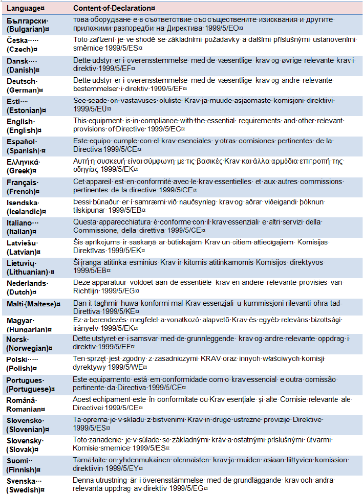
Declaration of Conformity, R&TTE Directive
1999/5/EC
This equipment is in compliance with the essential requirements of other relevant provisions of
Directive.
Declaration of Conformity
Hereby, Networks Inc. declares that this unit is in compliance with the essential requirements
and other relevant provisions of Directive 1999/5/EC.
To obtain the declaration of conformity (DoC) for R&TTE Directive, please access the follow-
ing URL address. http://www.merunetworks.com
Notice for customers: the following information is only applicable to equipment sold in coun-
tries applying EU directives. System may be operated in following countries:
EU Countries: Austria, Belgium, Bulgaria, Croatia, Cyprus, Czech Republic, Denmark, Esto-
nia, Finland, France, Germany, Greece, Hungary, Ireland, Italy, Latvia, Lithuania, Luxem-
bourg, Malta, The Netherlands, Poland, Portugal, Romania, Slovakia, Slovenia, Spain,
Sweden, United Kingdom.
This equipment can be operated in other non-European countries.
EFTA Countries: Norway and Switzerland
EU Applicants: Albania, Bosnia and Herzegovina
EU Candidate: Iceland, Macedonia and Montenegro
The following standards were applied:
•EMC-EN 301.489-1 Article 3.1 (b) of R&TTE Directive; EN 301.489-17 Article 3.1 (b) of
R&TTE Directive
•Health & Safety-EN60950-1
Device Name
(Nom de l'appareil) Industry Canada ID Number
(Industrie Canada Numéro d'identification)
AP822eV2 6749A-AP822EV2
AP822iV2 6749A-AP822IV2
Declaration of Conformity, R&TTE Directive 1999/5/EC 49
•Radio-EN 300 328 Article 3.1 (b) of R&TTE Directive; EN 301.893 Article 3.1 (b) of R&TTE
Directive
Declaration of Conformity, R&TTE Directive 1999/5/EC50
•The conformity assessment procedure referred to in Article 10.4 and Annex III of Directive
1999/5/EC has been followed.
VCCI Statement 51
This device is intended to be used in all EU and EFTA countries.
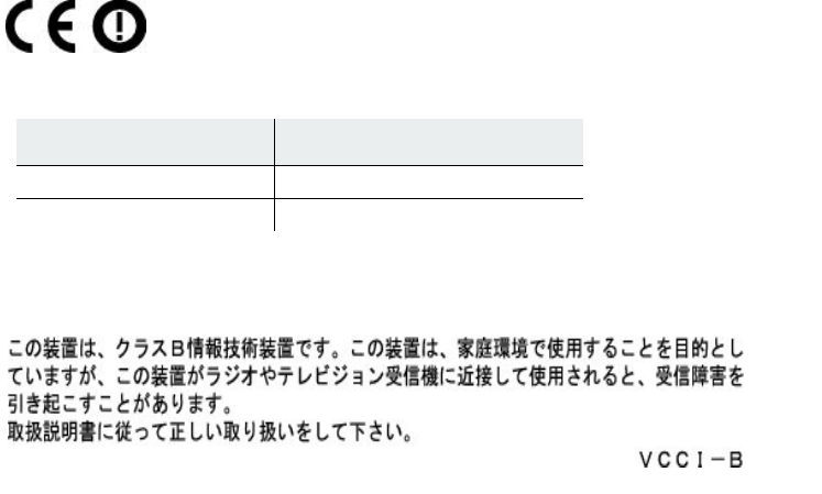
VCCI Statement
English Translation
This is a Class B product based on the standard of the Voluntary Control Council for Interfer-
ence from Information Technology Equipment (VCCI). If this is used near a radio or television
receiver in a domestic environment, it may cause radio interference. User shall install and use
the equipment according to the instruction manual.
General Information of RF Exposure
International Guidelines
This Device Meets International Guidelines for Exposure to Radio Waves.
The AP822eV2 and AP822iV2 device includes radio transmitters and receivers. It is designed
not to exceed the limits for exposure to radio waves (radio frequency electromagnetic fields)
recommended by international guidelines. The guidelines were developed by an independent
scientific organization (ICNIRP) and include a substantial safety margin designed to ensure
the safety of all persons, regardless of age and health.
As such the systems are designed to be operated as to avoid contact with the antennas by the
end user. It is recommended to set the system in a location where the antennas can remain at
Device Name Certification Report Number
AP822eV2 CE 0980
AP822iV2 CE 0980

General Information of RF Exposure52
least a minimum distance as specified from the user in accordance to the regulatory guide-
lines which are designed to reduce the overall exposure of the user or operator.
The World Health Organization has stated that present scientific information does not indicate
the need for any special precautions for the use of wireless devices. They recommend that if
you are interested in further reducing your exposure then you can easily do so by reorienting
antennas away from the user or placing he antennas at a greater separation distance then
recommended.
FCC Guidelines
This device meets FCC guidelines for exposure to radio waves.
The AP822eV2 and AP822iV2 include radio transmitters and receivers. It is designed not to
exceed the limits for exposure to radio waves (radio frequency electromagnetic fields) as ref-
erenced in FCC Part 1.1310. The guidelines are based on IEEE ANSI C 95.1 (92) and include
a substantial safety margin designed to ensure the safety of all persons, regardless of age and
health.
As such the systems are designed to be operated as to avoid contact with the antennas by the
end user. It is recommended to set the system in a location where the antennas can remain at
least a minimum distance as specified from the user in accordance to the regulatory guide-
lines which are designed to reduce the overall exposure of the user or operator.
The device has been tested and found compliant with the applicable regulations as part of the
radio certification process.
Separation Distance
MPE Distance Limit
0.82 mW/cm2 25 cm (9.84 inches) 1.00 mW/cm2
General Information of RF Exposure 53
The FCC recommends that if you are interested in further reducing your exposure then you
can easily do so by reorienting antennas away from the user or placing the antennas at a
greater separation distance then recommended or lowering the transmitter power output.
Industry Canada Guidelines
This device meets Industry Canada guidelines for exposure to radio waves.
The AP822eV2 and AP822iV2 include radio transmitters and receivers. It is designed not to
exceed the limits for exposure to radio waves (radio frequency electromagnetic fields) as ref-
erenced in Health Canada Safety Code 6. The guidelines include a substantial safety margin
designed into the limit to ensure the safety of all persons, regardless of age and health.
As such the systems are designed to be operated as to avoid contact with the antennas by the
end user. It is recommended to set the system in a location where the antennas can remain at
least a minimum distance as specified from the user in accordance to the regulatory guide-
lines which are designed to reduce the overall exposure of the user or operator.
Health Canada states that present scientific information does not indicate the need for any
special precautions for the use of wireless devices. They recommend that if you are inter-
ested in further reducing your exposure you can easily do so by reorienting antennas away
from the user, placing the antennas at a greater separation distance than recommended, or
lowering the transmitter power output.
Separation Distance
MPE Distance Limit
0.63 mW/cm2 20 cm (7.87 inches) 1.00 mW/cm2
Separation Distance
MPE Distance Limit
0.63 mW/cm2 20 cm (7.87 inches) 1.00 mW/cm2
General Information of RF Exposure54

Maximum EIRP 55
BAdditional Notes
Maximum EIRP
The transmit EIRP is the sum of the conductive transmit power, IEEE Std 802.11n multiple
stream effect, and the antenna gain. By default, Meru AP822 EIRP is set lower than the regu-
latory limit with the default antenna.
Dual Concurrent Same Band Operation
With grant of additional regulatory approval and Permit-but-Ask, users may configure two
radios in AP822 on the same band (i.e., both radios are on the 2.4 GHz but in the different or
same channels, and both radios are on the 5.x GHz but in the different or same channels).
However, user shall expect performance deterioration due to RF collision and collocation inter-
ference. It is important that users adopt external antennas, with extended coaxial pigtail
cables, with AP822eV2 in such use case. User shall place antennas far apart to reduce inter-
ference. Meanwhile, user shall also reduce AP822eV2 transmit power, for each radio, by at-
least 3 dBm from its default setting.
Manufacturing Information
The AP822 models are built in China. Contact Meru Networks for manufacturing related infor-
mation.
Distributed Antenna Systems (DAS)
Meru Networks does not certify or endorse any specific Distributed Antenna System (DAS)
vendors. Meru Networks will provide support to Meru Wi-Fi customers that use distributed
antennas within the terms and conditions of the MeruAssure Terms of Service and in accor-
dance with the customer's support agreement. Meru Customer Support will support Meru soft-
ware and hardware, and will work jointly with DAS vendors to identify and troubleshoot issues,
but any support related to RF issues, including RF coverage, shall be the responsibility of the
DAS vendor.
Air Handling Space Requirements56
Meru Networks recommends that customers use only a DAS that has been tested to work with
Meru hardware and software. Meru does not provide any site surveys, design or implementa-
tion of Wi-Fi over DAS. Meru recommends that customers obtain such services from a trained
and qualified systems integrator or from their DAS vendor.
Air Handling Space Requirements
When installing APs in an air-handling space, as described in Article 300.22(C) of the National
Electric Code® (2008 edition, pages 70-135 and 70-136), the unit should only be powered by
the Ethernet port (PoE), not by the AC-powered power supply.
Only AP822eV2 with plastic façade removed can be applied in air-handling space.
When the product is installed in air-handling spaces, the cables employed should be suitable
under NEC Articles 300.22 and 725 and marked accordingly, for use in plenums and air-han-
dling spaces with regard to smoke propagation, such as CL2-P, CL3-P, MPP or CMP.
The products should be installed in accordance with all applicable, local regulations and prac-
tices. Compliance applies only when the plastic facade is removed from the AP.
Frequencies Blocked for Regulatory
Compliance
These products are for indoor use only, in U-NII-1 and/or U-NII-3 band when Dynamic Fre-
quency Selection, DFS, from 5.25-5.35 GHz and 5.47-5.725 GHz, is disabled. With DFS
approval, these products can operate in U-NII-2 or U-NII-2e. To ensure compliance with local
regulations, be sure to set your Access Point to the country in which you are using the Access
Point.
Underwriters Laboratories
Use only listed e information technology equipment (ITE) I.T.E. equipment.
The unit is intended for installation in Environment A as defined in IEEE 802.3.af.All intercon-
nected equipments must be contained within the same building, including the interconnected
equipment's associated LAN connection.
Suitable for use in environmental air space in accordance with Section 300-22(c) of the
National Electrical Code, and Sections 2-128, 12-010(3) and 12-100 of the Canadian Electri-
cal Code, Part 1, C22.1.
Restriction of Hazardous Substances 57
Restriction of Hazardous Substances
European Community
This device complies the Restriction of Hazardous Substances Directive (RoHS) for its restric-
tion of the use of certain hazardous substances in electrical and electronic equipment for
European Union.
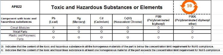
China
This device complies Administrative Measure on the Control of Pollution Caused by Electronic
Information Products or China RoHS. AP822 may contain hazardous substances are marked
with the EIP logo including an Environment Friendly Use Period (EFUP) value in 10 years.
Restriction of Hazardous Substances58

Cautions 59
CCautions and Warnings
The cautions and warnings that appear in this manual are listed below in English, German,
French, and Spanish. Changes or modifications not expressly approved by the party responsi-
ble for compliance could void the user’s authority to operate the equipment.
Cautions
A Caution calls your attention to a possible hazard that can damage equipment.
"Vorsicht” weist auf die Gefahr einer möglichen Beschädigung des Gerätes in.
Une mise en garde attire votre attention sur un risque possible d'endommagement de l'équi-
pement. Ci-dessous, vous trouverez les mises en garde utilisées dans ce manuel.
Un mensaje de precaución le advierte sobre un posible peligro que pueda dañar el equipo.
Las siguientes son precauciones utilizadas en este manual.
When changing the orientation of the antennas, be sure to slightly loosen the knurled ring before mov-
ing the antenna. Retighten the ring afterward. Otherwise, you might damage the internal cabling in the
AP.
Bei einer Neuausrichtung der Antennen muss vor Bewegung der Antenne der Rändelring leicht gelock-
ert werden. Anschließend den Ring wieder festziehen. Anderenfalls können die internen Kabel im AP
beschädigt werden.
En cas de modification d’orientation des antennes, veiller à desserrer légèrement la bague moletée
avant de réorienter l’antenne. Resserrer ensuite la bague, faute de quoi le câblage interne du point
d’accès pourrait être endommagé.
Al cambiar la orientación de las antenas, asegúrese de aflojar ligeramente el anillo estriado antes de
mover la antena. Luego vuelva a apretar el anillo. De otro modo, podría dañar el cableado interno del
punto de acceso.

Cautions60
The radiated output power of the access points is well below the radio frequency exposure limits. How-
ever, the Meru Access Point should be used in such a manner that the potential for human contact
during normal operation is minimized. To avoid the possibility of exceeding the radio frequency expo-
sure limits, you should keep a distance of at least 20 cm between you (or any other person in the vicin-
ity) and the Access Point antennas.
Die abgestrahlte Ausgangsleistung von Geräten von Meru Networks, Inc. liegt weit unter den Hochfre-
quenz-Expositionsgrenzwerten der. Die Meru Access Point Zugangspunkte von Meru Networks, Inc.
sollten jedoch so verwendet werden, dass das Potenzial für Kontakt mit Menschen während des nor-
malen Betriebs auf ein Mindestmaß beschränkt wird. Um die Möglichkeit einer Überschreitung der -
Hochfrequenz-Expositionsgrenzwerte zu vermeiden, ist ein Abstand von mindestens 20 cm zwischen
Ihnen (bzw. einer anderen Person in der Nähe) und den Zugangspunkt-Antennen zu wahren.
La puissance de rayonnement émise par les équipements Meru Networks, Inc. est très inférieure aux
limites d'exposition aux fréquences radio définies par la. Toutefois, les points d'accès de la série Meru
Access Point de Meru Networks, Inc. doivent être utilisés de façon à éliminer tout risque de contact
humain en fonctionnement normal. Pour éviter de dépasser les limites d'exposition aux fréquences
radio définies par la , il est impératif de préserver en permanence une distance supérieure ou égale à
20 cm entre l'utilisateur (ou toute personne se trouvant à proximité) et les antennes du point d'accès.
La potencia de radiación de los dispositivos de Meru Networks, Inc. está muy por debajo de los límites
de exposición a radiofrecuencia estipulados por la. No obstante, los puntos de acceso de la serie Meru
Access Point de Meru Networks, Inc. deben usarse de tal manera que se minimice la posibilidad de
contacto para el usuario durante la operación normal. Para evitar la posibilidad de exceder los límites
de exposición a radiofrecuencia establecidos por la, el usuario (o cualquier otra persona en torno) debe
mantenerse a una distancia de al menos 20 cm respecto a las antenas del punto de acceso.

Warnings 61
Warnings
A warning calls your attention to a possible hazard that can cause injury or death. The follow-
ing are the warnings used in this manual.
"Achtung" weist auf eine mögliche Gefährdung hin, die zu Verletzungen oder Tod führen kön-
nen. Sie finden die folgenden Warnhinweise in diesem Handbuch:
Un avertissement attire votre attention sur un risque possible de blessure ou de décès. Ci-
dessous, vous trouverez les avertissements utilisés dans ce manuel.
Una advertencia le llama la atención sobre cualquier posible peligro que pueda ocasionar
daños personales o la muerte. A continuación se dan las advertencias utilizadas en este
manual.
antenas del punto de acceso.
Exposure to Radio Frequency Radiation.
The installer of this radio equipment must ensure that the antenna is located or pointed such that it does
not emit an RF field in excess of Health Canada limits for the general population; consult Safety Code 6,
obtainable from Health Canada’s website http://www.hc-sc.gc.ca/rpb.
Exposition aux rayonnements à fréquence radioélectrique
L'installateur de cet équipement radio doit veiller à positionner et orienter l'antenne de telle sorte qu'elle
n'émette pas un champ radioélectrique supérieur aux limites définies par Santé Canada pour la popula-
tion générale. Consulter le Code de sécurité n° 6, disponible sur le site Web de Santé Canada à
l'adresse http://www.hc-sc.gc.ca/rpb.
Exposición a la radiación de radiofrecuencia.
El instalador de este equipo de radio debe cerciorarse de que la antena está localizada u orientada de
tal manera que no emita un campo de radiofrecuencia superior a los límites estipulados por Health
Canada para la población; consulte el Código de Seguridad 6 que podrá encontrar en el página web de
Health Canada, http://www.hc-sc.gc.ca/rpb.

Warnings62
With plastic covers removed, this product is suitable for use in environmental air-handling space in
accordance with the Section 300-22(c) of the National Electric Code and Sections 2- 128.12 - 010 (3)
and 12 - 100 of the Canadian Electrical Code. Part 1. C22. 1. For other countries, consult local authori-
ties for regulations.
Bei abgenommener Kunststoffabdeckung ist dieses Produkt zur Verwendung in einem Umgebung-
sluftraum gemäß Abschnitt 300-22(c) des National Electric Code und Abschnitt 2- 128.12 - 010 (3) und
12 - 100 des Canadian Electrical Code Teil 1. C22.1 geeignet. Die Vorschriften für andere Länder sind
bei den örtlichen Behörden erhältlich.
Sous réserve que ses couvercles de plastique soient déposés, cet appareil est adapté à une utilisation
dans les vides de construction des bâtiments selon la section 300-22(c) du code NEC (National Electric
Code) et les sections 2- 128.12 - 010 (3) et 12 - 100 du Code électrique du Canada, partie 1. C22. 1.
Pour tous les autres pays, consulter les organismes de réglementation locaux.
Una vez desprendidas las cubiertas de plástico, este producto es adecuado para su uso en el espacio
aéreo circundante en conformidad con la sección 300-22(c) del National Electric Code (Código Eléc-
trico Nacional de EE.UU.) y las secciones 2- 128.12 - 010 (3) y 12 - 100 del Código Eléctrico de
Canadá. Parte 1. C22. 1. En otros países, consulte a las autoridades locales competentes para infor-
marse acerca de las normativas vigentes.
Any Ethernet cables installed in air-handling spaces should be suitable under NEC Article 800.50 and
marked accordingly for use in plenums and air-handling spaces with regard to smoke propagation, such
as CL2-P, CL3-P, MPP (Multi Purpose Plenum), or CMP (Communications Plenum).
Alle Ethernet Kabel, die in Lüftungsräumen installiert werden, sollten gemäß NEC Artikel 800.50 geeig-
net sein und entsprechend zur Verwendung in Hohlräumen (Plenum) und Lüftungsräumen im Hinblick
auf Rauchausbreitung gekennzeichnet sein, z.B. CL2-P, CL3-P, MPP (Multi Purpose Plenum) oder
CMP (Communications Plenum).
Les câbles Ethernet installés dans un vide d’air doivent correspondre aux critères de l’article 800.50 du
code NEC et identifiés en conséquence comme adaptés à une utilisation dans les vides de construction
des bâtiments en matière de propagation de la fumée (marquages CL2-P, CL3-P, MPP (Multi Purpose
Plenum) ou CMP (Communications Plenum)).
Todos los cables Ethernet instalados en espacios aéreos deben cumplir con el artículo 800.50 del NEC
y estar marcados adecuadamente para su uso en espacios aéreos y plenums en lo concerniente a la
propagación de humo, tales como CL2-P, CL3-P, MPP (Plenum multifuncional), o CMP (Plenum de
comunicaciones).

Warnings 63
Indoor antennas must be positioned to observe minimum separation of 20 cm. (~ 8 in.) from all users
and bystanders. For the protection of personnel working in the vicinity of inside (downlink) antennas,
the following guidelines for minimum distances between the human body and the antenna must be
observed.
The installation of the indoor antenna must be such that, under normal conditions, all personnel cannot
come within 20 cm. (~ 8.0 in.) from any inside antenna. Exceeding this minimum separation will ensure
that the employee or bystander does not receive RF-exposure beyond the Maximum Permissible Expo-
sure according to local country regulatory approval.
Indoorantennen müssen so positioniert werden, dass ein Mindestabstand von 20 cm (ca. 8 Zoll) zu
allen Benutzern und anderen Personen gewahrt wird. Zum Schutz von Personal, das in der Nähe von
Innenantennen (Downlink) arbeitet, sind die folgenden Richtlinien für Mindestabstand zwischen dem
menschlichen Körper und der Antenne zu beachten.
Die Innenantenne muss so installiert werden, dass sich unter normalen Bedingungen kein Personal bis
auf weniger als 20 cm (ca. 8 Zoll) an eine Innenantenne annähern kann. Durch Überschreitung dieses
Mindestabstands wird sichergestellt, dass Mitarbeiter oder andere Personen keiner RF-Exposition über
die maximal zulässige Exposition (MPE; Maximum Permissible Exposure) gemäß FCC CFR 47,
Abschnitt 1.1310 (Grenzwerte für die allgemeine Bevölkerung/unkontrollierte Exposition) ausgesetzt
werden.
Les antennes intérieures doivent être positionnées de façon à respecter une distance minimum de 20
cm par rapport aux utilisateurs et aux tiers. Pour la protection du personnel travaillant à proximité des
antennes intérieures (liaison descendante), respecter les directives suivantes pour assurer des dis-
tances minimales entre les êtres humains et les antennes.
Toute antenne intérieure doit être installée de telle sorte que, dans des conditions normales, le person-
nel ne puisse s'en approcher à moins de 20 cm. Cette distance minimale est destinée à garantir qu'un
employé ou un tiers ne sera pas exposé à un rayonnement radioélectrique supérieur à la valeur maxi-
male autorisée, telle qu'elle est définie dans les limites d'exposition non contrôlées pour la population
par la réglementation de la FCC CFR 47, section 1.1310.
Las antenas interiores deben colocarse de manera que se observe una separación mínima de 20 cm.
(~ 8 pulg.) respecto a todos los usuarios y circunstantes. Para la protección del personal que trabaje en
las inmediaciones de las antenas interiores (receptoras), deben observarse las siguientes directrices
relativas a la distancia mínima entre el cuerpo humano y la antena.
La instalación de la antena interior debe efectuarse de tal modo que, en condiciones normales, ningún
miembro del personal pueda acercarse a menos de 20 cm. (~ 8,0 pulg.) de cualquier antena interior. El
cumplimiento de este mínimo de separación asegura que el empleado o circunstante no recibirá
exposición a radiofrecuencia por encima de la Exposición Máxima Permisible conforme a la normativa
FCC CFR 47, sección 1.1310, es decir, los límites asignados a la Exposición Incontrolada/Población
Civil.
Warnings64