Meru Networks OAP180 WLAN ENTERPRISE AP User Manual 3 4SR2 ReleaseNote
Meru Networks Inc. WLAN ENTERPRISE AP 3 4SR2 ReleaseNote
User Manual

Meru OAP180 Rugged Access
Point
Special Release Notes
Beta Release 3.4-SR2
Copyright © Meru Networks, Inc., 2003–2007. All rights reserved.
Other names and brands may be claimed as the property of others.
Document Number: 3.4-SR2 Rev. 1

2 of 24 Introduction
© 2007 Meru Networks, Inc.
Contents
zIntroduction
zOAP180 Access Point Features
zOAP180 Hardware Installation Instructions
zLimitations and Advisories
zDocumentation for this Release
zContacting Meru
Introduction
This special release note introduces the Meru OAP180 Access Point, a new outdoor
addition to the Meru Wireless LAN (WLAN) System. Read this note before installing or
using the OAP180 Access Point and the corresponding System Director version 3.4-SR2.
The release notes for System Director release 3.4-83 (March 2007) also apply to this
release for known issues. Please read both release notes prior to installing or using this
release.
OAP180 Access Point Features
The OAP180 Rugged Access Point is an outdoor AP with these features:
zDesigned for Harsh Conditions
zBest-in-class Meru AirShield Security
zOperation with all Meru Controllers and Access Points
zMultiple Antennas Supported for Specific Needs
OAP180 Access Point Features 3 of 24
© 2007 Meru Networks, Inc.
Designed for Harsh Conditions
The OAP180 Access Point with dual-radio is designed to provide secure Wi-Fi connec-
tivity to outdoor locations such as campuses, parking lots, and pole tops, or to harsh
indoor locations such as breweries, food processing plants or warehouses. The OAP180
includes basic Voice over WLAN (VoWLAN) support. Other features include:
zAutomatic AP discovery and configuration
zNo channel planning required with single channel installations
zController in the distribution or core layer extends VLAN trunks to the edge of the
network
zIntelligent load balancing of clients
zPoE (Power over Ethernet) support
zRoHS compliant
Best-in-class Meru AirShield Security
All Meru APs provide these multi-layered security policies that protect the data, the
network and the users simultaneously:
zLocal and RADIUS MAC Filtering
zWPA2, WPA, 802.1x, and WEP
zNo security information contained within access point
zOperates only with Meru controllers
zMultiple static or automatic security zones with individual security policies help
ensure separation of different user groups or dynamic VLAN assignments per user
based on Radius credentials - includes guest access security zone.
zThe OAP 180 also has a locking mechanism to secure it when mounted in public
areas.
Operation with all Meru Controllers and Access Points
The OAP180 operates with all currently supported Meru controllers and APs.
zCentralized dashboard monitors and troubleshoots the entire WLAN, including
OAP180 access points
zComplete support of release 3.4 standard and optional features such as N+1
Redundant Controller, Dual-Ethernet, and Per-User Firewall

4 of 24 Special Release Software for Meru Controllers
© 2007 Meru Networks, Inc.
Multiple Antennas Supported for Specific Needs
WLAN Client Support
The following WLAN clients are supported:
zDual 802.11a and 802.11b/g radios
zSimultaneous support for 802.11a, 802.11b, and 802.11g clients
zCo-channel interference management for reliable WLAN access
zBasic VoWLAN QoS support for small density deployments of voice clients
Special Release Software for Meru Controllers
Target Build Details
The following list describes the size and checksums for the system images, based on
the model of controller in use. Do not load onto your controller an image that is
intended for another controller model, or problems will occur.
zmeru-3.4.SR2-10-MC500-rpm.tar Checksum: 3958546189 Size: 43581440
zmeru-3.4.SR2-10-MC1000-rpm.tar Checksum:1023491239 Size:43663360
zmeru-3.4.SR2-10-MC1100-rpm.tar Checksum:1359995275 Size:43663360
zmeru-3.4.SR2-10-MC3000-rpm.tar Checksum:1023491239 Size:43663360
Install the Special Release Image on Your Controller
The installation of the special release image is performed with the normal Meru
upgrade procedure, summarized in the following steps.
1. Obtain the system image.
In this example, the special release image for the MC500, meru-3.4.SR2-10-MC500-
rpm.tar 3958546189 43581440, is retrieved using FTP from the images directory on
the server named myserver using the username user1 and password userpass. Use the
upgrade system command to upgrade the system. To configure the system so that you
do not need to type the FTP username and password when transferring files, use the

OAP180 Hardware Installation Instructions 5 of 24
© 2007 Meru Networks, Inc.
ip ftp|sftp|scp|tftp username and ip ftp|sftp|scp password commands. (Using
these commands is optional. If you do not set the username and password before trans-
ferring files, you must provide the username and password when prompted.)
mc500# configure terminal
mc500(config)# ip ftp username user1
mc500(config)# ip ftp password userpass
mc500(config)# ^Z
mc500# dir ftp://myserver/images/
total 134576
-rw-rw-r-- 1 root root 21790720 Jul 14 17:03 meru-3.2SR2-9-
MC500.tar
mc500# cd images
mc150# copy ftp://myserver/images/meru-3.4.SR2-10-MC500-
rpm.tar
2. If you see an error message stating that there is not enough free disk space, use
the show flash command to see if there are previous images on the flash. Delete
the previous image using the delete flash version command. Then try the copy
command again.
3. After the image transfer is complete, use show flash to verify the system is on the
flash.
4. Enter the upgrade system version command to update the controller and OAP
software:
mc500# upgrade system 3.4.SR2-10
The system is now upgraded. Log in as admin to access the system.
OAP180 Hardware Installation Instructions
Perform the procedures in the following sections to install the OAP180 and configure
the controller to use this special release.
Unpack the OAP180
Plan the Location
Test Basic Link Operation
Mount the Unit
Connect External Antennas and Ground Wire to OAP180
Connect Cables to the Unit
Connect the Power Injector
Align Antenna
Check the OAP180 for Activity
Configure the OAP180 Access Point
6 of 24 OAP180 Hardware Installation Instructions
© 2007 Meru Networks, Inc.
Unpack the OAP180
Confirm that the OAP180 shipping box contains the following items:
zMeru Networks Meru OAP180 Outdoor Access Point (see Figure 1).
Figure 1: OAP180
zWall/Pole Mount Hardware Kit for mounting OAP180 to a 1.5” to 2” diameter steel
pole or tube or as part of a radio or tower structure
zBar code labels listing the MAC address and serial number (for Beta test, these are
already attached to the unit)
zOutdoor CAT5 Ethernet cable—100 feet
zPoE injector with power cord
Additional Equipment Needed
In addition to the hardware supplied by Meru Networks, you need the following:
Required
zStandard Ethernet cable to connect the POE injector to a switch or controller
zTwo external antennas (provided by Meru Networks only for Beta test)
Optional
zGround wire for the OAP180
zRF coaxial cable to connect the antenna to the OAP180
OAP180 Hardware Installation Instructions 7 of 24
© 2007 Meru Networks, Inc.
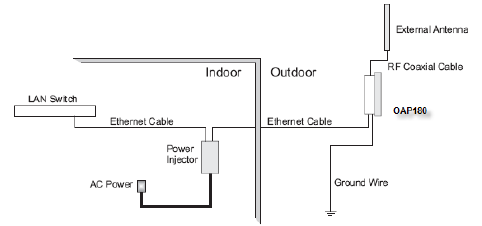
Plan the Location
When you plan the OAP180 physical configuration, include the elements shown in this
drawing:
Figure 2: Sample Physical Layout
Radio Position Planning
Never construct a radio mast, pole, or tower near overhead power lines. In addition,
local regulations may limit or prevent construction of a high radio mast or tower. If
your OAP180 link requires a high radio mast or tower, consult a professional contractor
for advice. Once the required antenna height has been determined, other factors
affecting the precise position of the OAP180 must be considered.
zBe sure there are no other radio antennas within 2 m (6 ft) of the OAP180.
zPlace the OAP180 away from power and telephone lines.
zAvoid placing the OAP180 too close to any metallic, reflective surfaces, such as roof-
installed air-conditioning equipment, tinted windows, wire fences, or water pipes.
Radio Interference
Avoiding radio interference is an important part of wireless planning. Interference is
caused by other radio transmissions using the same or an adjacent channel frequency.
You should first scan your proposed site using a spectrum analyzer to determine if
there are any strong radio signals using the 802.11a or 802.11bg channel frequencies.
Always use a channel frequency that is furthest away from another signal.
Weather Conditions
Take into account any extreme weather conditions that are known to affect your loca-
tion. Consider these factors:
zTemperature — The OAP180 is tested for normal operation in temperatures from -
40°C to 140°C. Operating in temperatures outside of this range may cause the unit
to fail.
8 of 24 OAP180 Hardware Installation Instructions
© 2007 Meru Networks, Inc.
zWind Velocity — The OAP180 can operate in winds up to 44 m/s and survive higher
wind speeds up to 66 m/s. You must consider the known maximum wind velocity
and direction at the site and be sure that any supporting structure, such as a pole,
mast, or tower, is built to withstand this force.
zLightning — The OAP180 includes its own built-in lightning surge protection.
However, you should make sure that the unit, any supporting structure, and cables
are all properly grounded. Additional protection using lightning rods, lightning
arrestors, or surge suppressors may also be employed. Antenna sockets should
point upwards in a vertical manner
zRain — The OAP180 is weatherproofed against rain. Also, prolonged heavy rain has
no significant effect on the radio signal. However, it is recommended to apply
weatherproof sealing tape around the Ethernet port and antenna connectors for
extra protection. If moisture enters a connector, it may cause a degradation in
performance or even a complete failure of the link.
zSnow and Ice — Falling snow, like rain, has no significant effect on the radio signal.
However, a build up of snow or ice on antennas may cause the link to fail. In this
case, the snow or ice has to be cleared from the antennas to restore operation of
the link.
Ethernet Cabling
When a suitable antenna location has been determined, plan a cable route from the
OAP180 outdoors to the power injector module indoors. Consider these points:
zThe Ethernet cable length should never be longer than 100 m (328 ft).
zDetermine a building entry point for the cable.
zDetermine if conduits, bracing, or other structures are required for safety or
protection of the cable.
zFor lightning protection at the power injector end of the cable, consider using a
lightning arrestor immediately before the cable enters the building.
Grounding
It is important that the OAP180, cables, and any supporting structures are properly
grounded. The OAP180 unit includes a grounding screw for attaching a ground wire.
Be sure that grounding is available and that it meets local and national electrical
codes.
Test Basic Link Operation
Set up the OAP180 on the ground, either outdoors or indoors. Connect the unit as indi-
cated in this document and perform the basic configuration tasks outlined below.
When you are satisfied that the OAP180 is operating correctly, proceed to mounting
the unit in the intended location.
OAP180 Hardware Installation Instructions 9 of 24
© 2007 Meru Networks, Inc.
Mount the Unit
The OAP180 can be mounted on the following two surfaces (brackets are included):
z1.5 to 2 inch diameter pole
zWall
Mounting OAP180 with the Pole-Mounting Bracket
Perform the following steps to mount the unit to a 1.5 to 2 inch diameter steel pole or
tube using the mounting bracket:
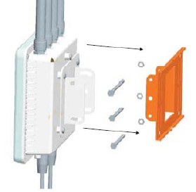
1. Attach the OAP180 to the mounting bracket shown in Figure 3.
Figure 3: Square Mounting Bracket Attaches to Bottom of OAP180
10 of 24 OAP180 Hardware Installation Instructions
© 2007 Meru Networks, Inc.
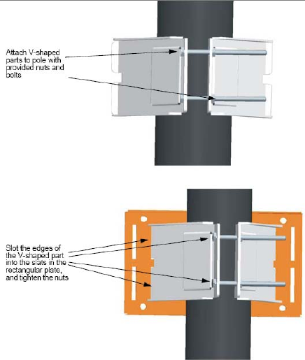
2. Place the V-shaped part of the bracket around the pole and tighten the securing
nuts just enough to hold the bracket to the pole. (The bracket may need to be
rotated around the pole during the alignment process.)
Note:
Always attach the bracket to a pole with the open end of the mounting
grooves facing up.
3. Use the included nuts to tightly secure the wireless OAP180 to the bracket.
OAP180 Hardware Installation Instructions 11 of 24
© 2007 Meru Networks, Inc.
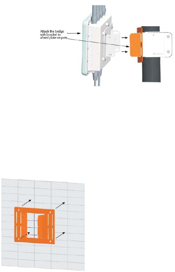
4. Connect the OAP180 bracket and the pole bracket. See Figure 4.
Figure 4: Connecting the Two Brackets
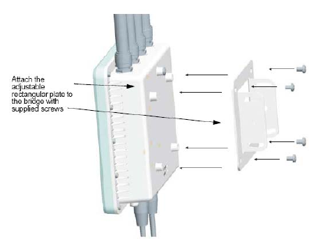
Mounting OAP180 with the Wall-Mounting Bracket
Attach the bracket to a wall with the flat side flush against the wall (see Figure 5).
Perform the following steps to mount the unit to a wall using the wall-mounting
bracket:
1. Position the bracket in the intended location and mark the position of the four
mounting screw holes.
2. Drill holes in the wall that match the screws and wall plugs included in the bracket
kit, and then secure the bracket to the wall.
Figure 5: Attaching Bracket to Wall
3. Use the included nuts to tightly secure the OAP180 to the bracket.
OAP180 Hardware Installation Instructions 13 of 24
© 2007 Meru Networks, Inc.
Connect External Antennas and Ground Wire to OAP180
When deploying an OAP180, first mount external antennas and then connect them to
the OAP180. Follow these steps:
1. Mount the external antenna on the same supporting structure as you did the
OAP180, within 3 m (10 ft) of it, using the bracket supplied in the antenna
package.
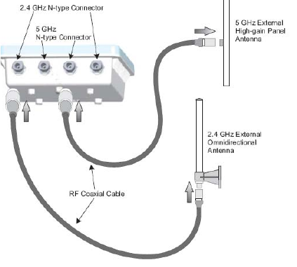
2. Connect the antenna to the OAP180’s N-type connector using the RF coaxial cable
provided in the antenna package.
Figure 7: Connect the Antenna Cables
3. Apply weatherproofing tape to the antenna connectors to help prevent water
entering the connectors.
14 of 24 OAP180 Hardware Installation Instructions
© 2007 Meru Networks, Inc.
Connect Cables to the Unit
Use only the provided Ethernet cable in step 1. Do not shorten this cable as the path
loss is needed. During periods of lightning activity, do not connect or disconnect cables
or otherwise work with the OAP180.
Perform the following steps to attach the Ethernet cable and ground wire:
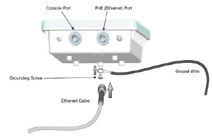
1. Using the included cable, attach the Ethernet cable to the Ethernet port on the
OAP180. See Figure 8.
Figure 8: Connecting the Ethernet Cable and Ground Wire
2. For extra protection against rain or moisture, apply weatherproofing tape (not
included) around the Ethernet connector.
3. Ground the unit with an appropriate grounding wire (not included) by attaching it
to the grounding screw on the unit. See Figure 8.
Caution!
Be sure that grounding is available and that it meets local and national
electrical codes. For additional lightning protection, use lightning rods, lightning
arrestors, or surge suppressors.
OAP180 Hardware Installation Instructions 15 of 24
© 2007 Meru Networks, Inc.
Connect the Power Injector
Caution!
Do not locate the power injector outdoors. The unit is for indoor use only.
Note:
The wireless Ethernet port does not support Power over Ethernet (PoE) based
on the IEEE 802.3af standard. Do not try to power the unit by connecting it directly to a
network switch that provides IEEE 802.3af PoE. Always connect the unit to the included
power injector module.
Perform the following steps to connect the power injector:
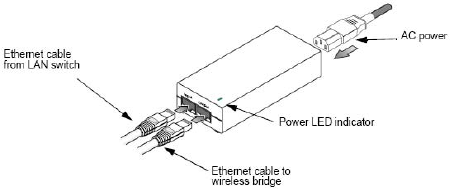
1. Connect the other end of the provided Ethernet cable (already connected to the
OAP180) to the RJ-45 port labeled Output on the power injector. See Figure 9.
Figure 9: Connecting the Power Injector
2. Connect a straight-through unshielded twisted-pair (UTP) cable (not included)
from a local LAN switch to the RJ-45 port labeled Input on the power injector. See
Figure 9. Use Category 5e or better UTP cable for 10/100BASE-TX connections.
Note:
The RJ-45 port on the power injector is an MDI port. If connecting directly to a
computer for testing the link, use a crossover cable.
3. Insert the power cable plug directly into the standard AC receptacle on the power
injector. See Figure 9.
4. Plug the other end of the power cable into a grounded, 3-pin socket, AC power
source.
Note:
For International use, you may need to change the AC line cord. You must use
a line cord set that has been approved for the receptacle type in your country.
5. Check the LED on top of the power injector to be sure that power is being supplied
to the OAP180 through the Ethernet connection.
16 of 24 OAP180 Hardware Installation Instructions
© 2007 Meru Networks, Inc.
Align Antenna
After the OAP180 unit is mounted, connected, and the radios are operating, the
antennas must be accurately aligned to ensure optimum performance of the OAP180
links. In this point-to-multipoint configuration all OAP180 nodes must be aligned with
the root OAP180 antenna.
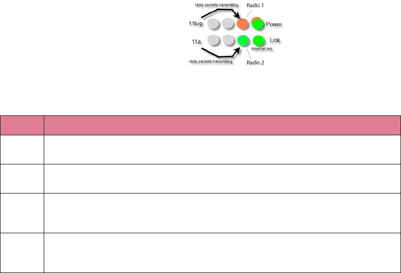
Check the OAP180 for Activity
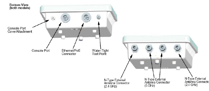
Check the OAP180 LEDs for activity. Four of the eight LEDs on the bottom of the
OAP180 indicate activity; four LEDs are not used at this time. Check the four active
LEDs to determine if the AP is working.
The grey LEDs in the illustration are not currently used. The following chart explains
the meanings for the remaining LEDs.
LEDs Function
Power When power is applied to the system this LED initially turns amber, then blinks green when
the system power check is applied, and then is a steady green when power is on.
Ethernet
Link The Ethernet Link LED blinks green when a link has been detected and is in use.
Radio 1
11bg
The 11bg connection LED blinks amber when radio packets are being transmitted and when
the radio is beaconing. If there is traffic over the air on this radio, the blinking rate
increases.
Radio 2
11a
The 11a connection LED blinks green when radio packets are being transmitted and when
the radio is beaconing. If there is traffic over the air on this radio, the blinking rate
increases.

OAP180 Hardware Installation Instructions 17 of 24
© 2007 Meru Networks, Inc.
Configure the OAP180 Access Point
Once the OAP180 is plugged in, the Meru controller will detect and connect the
OAP180. The OAP180 can then be further configured through either the Controller
GUI or CLI.
Configure OAP180 Radio Operation with the Web UI
Configure OAP180 Radio Antennas with the CLI
Configure OAP180 Radio Operation with the CLI
Configure OAP180 Radio Operation with the Web UI
To use the Web UI to set up the OAP180, follow these steps from the controller:
1. Click Configuration and then Radio from the Devices list. A table of Wireless AP
Interface Details displays.
2. Select the checkbox of the second wireless interface of the OAP180 that requires
modification, and then click Settings. The Wireless Interface Configuration Update
page displays.
3. From the Channel drop-down list, select the channel the interface will use
(channels have been filtered to only reflect appropriate selections).
4. From the RF Band Selection drop-down list, select 802.11a
5. Click OK to save your change and return to the Wireless Interface Configuration
page.
6. Select the checkbox for the first wireless interface of the OAP, and click Settings.
The Wireless Interface Configuration displays.
7. From the Channel drop-down list, select the channel the interface will use
(channels have been filtered to only reflect appropriate selections).
8. From the RF Band Selection drop-down list, select 802.11b, 802.11g, or
802.11bg. Default mode is 802.11bg.
9. Click OK to save your change and return to the Wireless Interface Configuration
page.
10. Continue setting any other OAPs as needed, by repeating the above steps.
11. Save this configuration by clicking on Save.
18 of 24 OAP180 Hardware Installation Instructions
© 2007 Meru Networks, Inc.
Configure OAP180 Radio Operation with the CLI
To configure radio parameters of OAP180 through the IOSCLI, follow these steps from
controller. This example uses AP ID 1 and interface IDs 1 and 2:
1. First, configure AP ID 1 and Interface ID 1 (B/G Interface):
MC3000# configure terminal
MC3000(config)# interface Dot11Radio 1 1
MC3000(config-if-802)# channel 1
MC3000(config-if-802)# rf-mode 802.11g
MC3000(config-if-802)# exit
MC3000(config)#
2. Next, configure AP ID 1 and Interface ID 2 (A Interface):
MC3000(config)# interface Dot11Radio 1 2
MC3000(config-if-802)# channel 48
MC3000(config-if-802)# exit
MC3000(config)# exit
3. Save the configuration:
MC3000# copy running-config startup-config
4. Check the configuration of both interfaces:
MC3000# show interfaces Dot11Radio 1 1
Wireless Interface Configuration
AP ID : 1
AP Name : OAP180
Interface Index : 1
AP Model : OAP180
Description : ieee80211-1-1
Administrative Status : Up
Operational Status : Disabled
Last Change Time : 2007/04/26 01:18:29
Radio Type : RF3
MTU (bytes) : 2346
Channel : 1
Short Preamble : on
RF Band Support : 802.11bg
RF Band Selection : 802.11g
Antenna Selection : Left
Transmit Power (dBm) (low,medium,high) : 20,20,20
AP Mode : Normal
Fixed Channel : off
Scanning Channels :
Protection Mechanism : 802.11-1999
Protection Mode : auto
Number of Antennas : 1
Dual abg Support : off
OAP180 Hardware Installation Instructions 19 of 24
© 2007 Meru Networks, Inc.
MC3000# show interfaces Dot11Radio 1 2
Wireless Interface Configuration
AP ID : 1
AP Name : OAP180
Interface Index : 2
AP Model : OAP180
Description : ieee80211-1-2
Administrative Status : Up
Operational Status : Disabled
Last Change Time : 2007/04/26 01:18:29
Radio Type : RF3
MTU (bytes) : 2346
Channel : 40
Short Preamble : off
RF Band Support : 802.11a
RF Band Selection : 802.11a
Antenna Selection : Right
Transmit Power (dBm) (low,medium,high) : 17,17,17
AP Mode : Normal
Fixed Channel : off
Scanning Channels :
Protection Mechanism : 802.11-1999
Protection Mode : auto
20 of 24 OAP180 Hardware Installation Instructions
© 2007 Meru Networks, Inc.
Configure OAP180 Radio Antennas with the CLI
Configure OAP180 antennas with the following CLI commands. This example uses AP ID
10 and radios 1 and 2:
1. Enter the Radio sub-mode from global configuration, by specifying the AP ID (10 in
the example) and first interface that you intend to configure:
default# configure terminal
default(config)# interface Dot11Radio 10 1
2. Enter the antenna-property submode interface 1:
default(config-if-802)# antenna-property 1
3. Set the antenna type to External:
default(config-if-802-antenna)# type External
4. Set the antenna band to dual, and exit the mode:
default(config-if-802-antenna)# rfband dual
default(config-if-802-antenna)# end
default(config-if-802)# end
default(config)# end
5. Reboot the system.
6. Check the configuration of both interfaces:
default# show interfaces Dot11Radio 1 1
default# show interfaces Dot11Radio 1 2
Limitations and Advisories 21 of 24
© 2007 Meru Networks, Inc.
Limitations and Advisories
Known Bugs for this Release
!
Other Significant Issues with this Release
None
Regulatory Information
Radio
zFCC Part 15
zCanada RSS210
zEN 300 328 V1.6.1 (11/2004)
zEN 301 893 V1.3.1 (08/2005)
zJapan Technical Regulations
EMC
zFCC Part 15
zEN 301 489-17 V1.2.1 (08/2002)
zJapan VCCI
BUG ID Summary
22 of 24 Regulatory Information
© 2007 Meru Networks, Inc.
Safety
zcUL 60950-1 First Edition
zIEC/EN 60950-1 First Edition
zwith national deviations
zUL 50; Enclosures for Electrical Equipment
FCC Statement
This equipment has been tested and found to comply with the limits for a Class B
digital device, pursuant to Part 15 of the FCC Rules. These limits are designed to
provide reasonable protection against harmful interference in a residential installa-
tion. This equipment generates, uses and can radiate radio frequency energy and, if
not installed and used in accordance with the instructions, may cause harmful inter-
ference to radio communications. However, there is no guarantee that interference
will not occur in a particular installation. If this equipment does cause harmful inter-
ference to radio or television reception, which can be determined by turning the
equipment off and on, the user is encouraged to try to correct the interference by one
of the following measures:
zReorient or relocate the receiving antenna.
zIncrease the separation between the equipment and receiver.
zConnect the equipment into an outlet on a circuit different from that to which the
receiver is connected.
zConsult the dealer or an experienced radio/TV technician for help.
FCC Caution
Any changes or modifications not expressly approved by the party responsible for
compliance could void the user’s authority to operate this equipment.
This device complies with Part 15 of the FCC Rules. Operation is subject to the
following two conditions: (1) This device may not cause harmful interference, and (2)
this device must accept any interference received, including interference that may
cause undesired operation.
This device and its antenna(s) must not be co-located or operation in conjunction with
any other antenna or transmitter.
FCC Radiation Exposure Statement
This equipment complies with FCC radiation exposure limits set forth for an uncon-
trolled environment. This equipment should be installed and operated with minimum
distance 20cm between the radiator & your body.

Documentation for this Release 23 of 24
© 2007 Meru Networks, Inc.
For product available in the USA market, only channel 1~11 can be operated.
Selection of other channels is not possible.
FCC NOTICE
To comply with FCC part 15 rules in the United States, the system must be profession-
ally installed to ensure compliance with the Part FCC 15 certification
It is the responsibility of the operator and professional installer to ensure that only
certified systems are deployed in the United States. The use of the system in any other
combination (such as co-located antennas transmitting the same information) is
expressly forbidden.
CE Statement
Hereby, Meru, declares that this device is in compliance with the essential require-
ment and other relevant provisions of the R&TTE Driective 1999/5/EC.
This device will be sold in the following EEA countries: Austria, Italy, Belgium, Liecht-
enstein, Denmark, Luxembourg, Finland, Netherlands, France, Norway, Germany,
Portugal, Greece, Spain, Iceland, Sweden, Ireland, United Kingdom, Cyprus, Czech
Republic, Estonia, Hungary, Latvia, Lithuania, Malta, Slovakia, Poland, Slovenia.
Documentation for this Release
In addition to these release notes, the standard documentation and release notes for
the 3.4 release apply to this release and describe the full System Director functionality
and known issues.
zMeru Wireless LAN System Release 3.4 Release Note
zMeru Wireless LAN System Getting Started Guide
zMeru Controller Installation Guide
zMeru Wireless LAN System Command Reference
zMeru Wireless LAN System Configuration Guide

24 of 24 Contacting Meru
© 2007 Meru Networks, Inc.
Contacting Meru
You can visit Meru Networks on the Internet at this URL:
http://www.merunetworks.com
Click Support to view Meru Customer Services and Support information.
Customer Services and Support
For assistance, contact Meru Customer Services and Support 24 hours a day at 1-888-
637-8952 (1-888-Meru-WLA(N)) or 1-408-215-5305.
Send email to support@merunetworks.com.
Meru Customer Services and Support provide end users and channel partners with the
following:
zTelephone technical support
zSoftware update support
zSpare parts and repair service