Meru Networks PSM3X MULTI RADIO 802.11a/b/g/n WIRELESS LAN ACCESS POINT User Manual AP Install AP300
Meru Networks Inc. MULTI RADIO 802.11a/b/g/n WIRELESS LAN ACCESS POINT AP Install AP300
Users Manual

Safety Precautions
© 2010 Meru Networks, Inc. Installing AP300 11
AP1000 Beta Test
Chapter 2
Installing AP300
This chapter describes how to install and configure an AP300. It contains the following sections:
Safety Precautions
Unpack the AP300
Determine Power Requirements
Installation Requirements
Install the AP300
Check AP300 LED Activity
Check AP300 LED Activity
Where to Go From Here
Safety Precautions
IMPORTANT—Read and follow the regulatory instructions in Appendix B before installing and operating
this product.
If an optional power supply is used, it must be one supplied by Meru Networks.
The AP300 is intended only for installation in Environment A as defined in IEEE 802.3af. All intercon-
nected equipment must be contained within the same building, including the interconnected equip-
ment's associated LAN connection.

12 Meru Access Point Installation Guide © 2010 Meru Networks, Inc.
Best Practices for an AP300/AP1000 Network
AP1000 Beta Test
Best Practices for an AP300/AP1000 Network
Read this section if you have both AP1000 and AP320i active simultaneously on the same network. The
following best practices should be followed to get optimal performance from such a mixed network.
AP320i and AP300 are interchangeable and fully compatible to share a virtual cell. It's like having
two AP300s with different antennas. The only difference is that AP320i is detected as a such in the
UI of the controller.
If possible, do not deploy AP1000 and AP300/AP320i at the same physical location; we recommend
that there be no overlapping coverage between AP1000 and AP300.
If AP1000 and AP300/AP320i do have overlapping coverage, you have two options. Deploy them on
seperate channels or make sure the ESS profiles on both AP types are unique. The chart below shows
two ESS scenarios, one supported, one not supported.
Assumptions for the above best practices include:
AP1000 is using Virtual Port with BSSID Virtual Cell.
AP320i is using Virtual Port with BSSID Virtual Cell.
AP1000s and AP300s are on the same channel. (AP1000 and AP320i could also be on different
channels.)
AP1000s and AP320i is are on the same controller. (AP1000 and AP320i could also be on different
controllers as long as each controller has a unique controller index.)
Supported ESS Scenario AP1000 Configuration AP320i Configuration
Two Unique ESS profiles ESS Profile name in
controller is UniqueName1 ESS Profile name in
controller is UniqueName2
AP1000 and AP320i SSID
string over the air Meru Meru
Unsupported ESS Scenario AP1000 Configuration AP320i Configuration
Same ESS profiles ESS Profile name in
controller is same name ESS Profile name in
controller is same name
AP1000 and AP320i SSID
string over the air Meru Meru

Unpack the AP300
© 2010 Meru Networks, Inc. Installing AP300 13
AP1000 Beta Test
Unpack the AP300
The AP300 series has five models as shown below.
Confirm that the AP300 shipping package contains these items:
AP300 with attached mounting bracket
Six antennas (four for PSM3x)
Screws for the mounting bracket
Model Radios
PSM3x One a/b/g/n, one spectrum
AP320 Two a/b/g/n
AP311 One a/b/g/n, one a/b/g
AP310 One a/b/g/n
AP302 One a/b/g

14 Meru Access Point Installation Guide © 2010 Meru Networks, Inc.
Determine Power Requirements
AP1000 Beta Test
Determine Power Requirements
Power requirements vary, depending on which AP300 radios are deployed and what MIMO mode is used.
See the chart below for supported power sources for different radio configurations.
802.af PoE Usage
When using System Director 3.6/4.0/4.1 and 802.3af PoE, Meru supports radios set to any MIMO settings
except 3x3 on dual radios. This is because two radios set to 3x3 MIMO using an 802.3af switch may not
have enough power if the cable is too long. Shorter cables frequently work, however. Meru supports:
Single 3x3 radio
Dual 2 x 2 radios
Dual radio with one set to 2x2 and the other one set to 3x3
When using System Director 4.0 and 802.3af, the AP300 MIMO configuration is limited to the following:
3x3 for the 5 GHz radio
2x2 for the 2.4 GHz radio
802.3at PoE Usage
When using System Director 3.6/4.0/4.1 and 802.3at, the following radio combinations are recom-
mended:
Single 3x3 radio
Dual 2 x 2 radios
Dual radio with one set to 2x2 and the other one set to 3x3
Radio 1 MIMO Radio 2 MIMO 802.3af PoE 802.3at PoE DC Power
2x2 2x2
2x2 3x3
3x3 2x2
3x3 3x3 Do not
recommend
limitation
below

Installation Requirements
© 2010 Meru Networks, Inc. Installing AP300 15
AP1000 Beta Test
Dual 3x3 radios are recommended with a limitation. Use 802.3at power for two 3x3 MIMO radios
when the switch has a high enough power output to support all devices on the PoE. Calculate the
amount of power needed by each AP300/AP300i in 3x3 mode (13 watts), add that to power required
by other PoE devices on the switch and compare that value to the total power output from the
switch.
The calculation for 802.3at PoE use looks something like this:
(Number of AP300s * 13watts) + (sum of all other PoE devices power requirements) <= switch
power provided
For a list of supported PoEs, see the appendix Supported Power Over Ethernet Devices for Meru APs
Installation Requirements
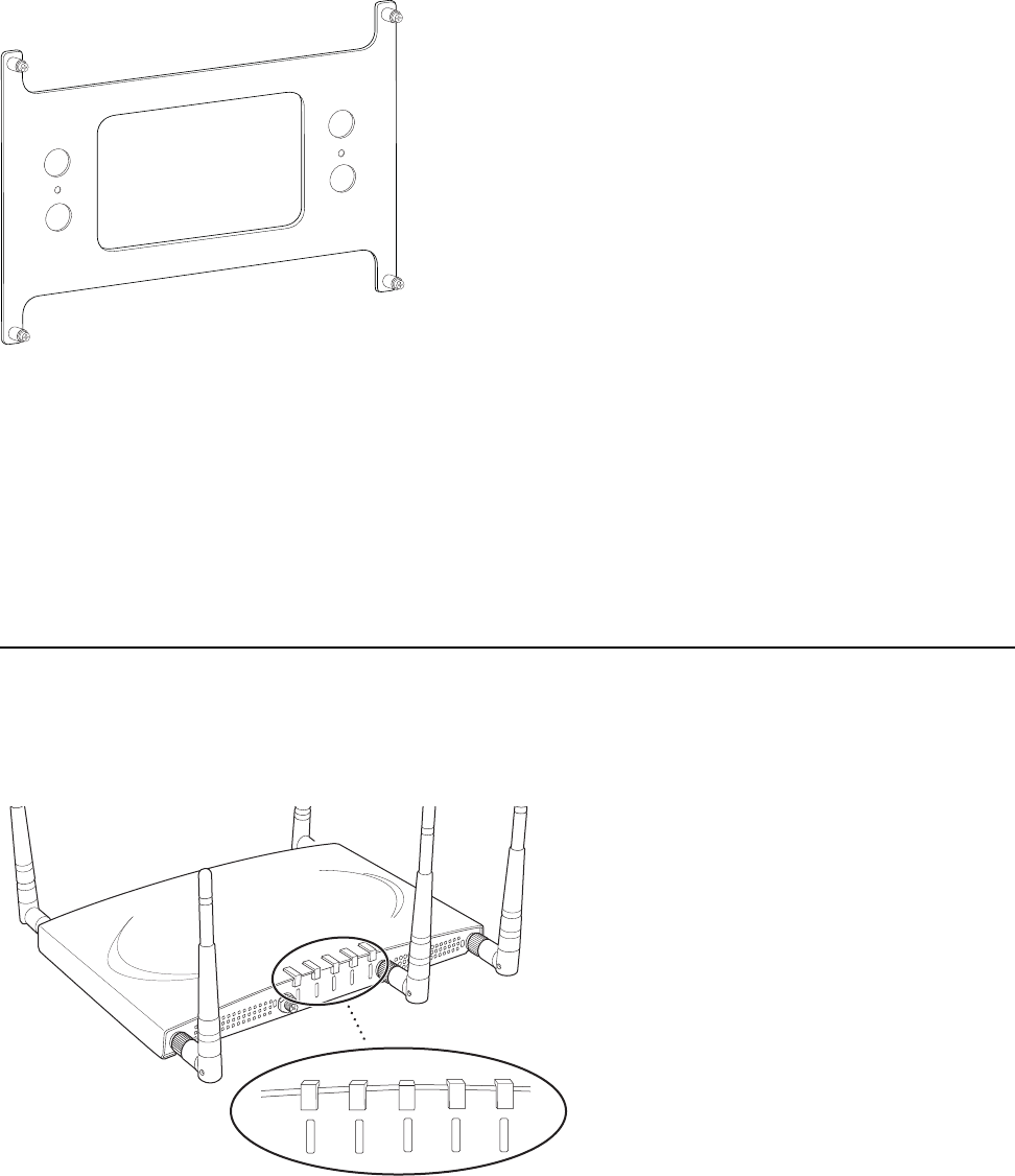
An array of holes on the mounting bracket allows the AP300 to be mounted on the wall and over junc-
tion boxes or molly bolts. There are holes for passing the PoE Ethernet or external power supply cable
through the bracket if the bracket is mounted on a junction box. A template of this bracket is included
in Appendix E of this guide.
The AP300 has a security cable slot so you can lock the AP300 with a standard security cable, such as
those used to secure laptop computers.
Purchase optional mounting kits to mount the AP300 either from the ceiling or inside an enclosure:
Suspended Ceiling Rail Mounting Kit: ACC-MNT-SCRMKIT
Above Suspended Ceiling Mounting Kit (T-Bar Hanger): ACC-MNT-ASCMKIT
Inside a Hoffman Enclosure using Hoffman compatible mounting bracket: ACC-AP300-BHE (enclosure
not provided)
Above hanging ceiling tiles. Suitable for use in environmental air space in accordance with the
Section 300-22(c) of the National Electric Code and Sections 2- 128.12 - 010 (3) and 12 - 100 of the
Canadian Electrical Code. Part 1. C22. 1.
To complete AP300 installation, you need the items listed below.
Installation Type Items Required
Horizontal mounting None
Vertical mounting over a wall
stud
Two #6 x 2" wood screws for a wood stud; or
Two #6 x 1½” metal screws for a metal stud
Mounting bracket

16 Meru Access Point Installation Guide © 2010 Meru Networks, Inc.
Install the AP300
AP1000 Beta Test
Additional Equipment
A power source is needed to power the AP300. See Determine Power Requirements.
Install the AP300
Select a Location
Attach the Provided Antennas
Install the Remote Antenna Mount (optional)
Install External ACC-ANT-MIMO-MNT Antenna with Three Connectors (optional)
Install Remote ACC-ANT-6ABGN-24 Antenna with Six Connectors (optional)
Install Antennas With One Connector (optional)
Install the Access Point
Select a Location
All AP300 interconnected equipment, including the associated LAN connection, must be contained
within the same building. In addition, the AP300 location should meet the following conditions:
Vertical mounting on sheetrock
Two #6 x 1" screws
Two #4-6 x 7/8” ribbed plastic wall anchors
Mounting bracket
Horizontal mounting below a
hanging ceiling
Two caddy fasteners
Two plastic spacers
Two keps nuts (with attached lock washer)
Mounting bracket
Using existing third party
brackets
Use included shoulder screws
Mounting above a ceiling tile
Two T-rail clips
One T-box hanger
One bracket mounting clip
Mounting bracket
Installation Type Items Required
Install the AP300
© 2010 Meru Networks, Inc. Installing AP300 17
AP1000 Beta Test
Relatively unobstructed access to the stations the AP serves. Select a location with minimal physical
obstructions between the AP and the wireless stations. In an office with cubicles, mounting the APs
below a hanging ceiling (plenum is supported) or the wall near the ceiling provides the least
obstructed communications path. On a wall, orient the AP300 horizontally so that you can read the
Meru logo without tilting your head at 90 degrees - this orientation provides optimum MIMO
performance.
Access to wall outlet or a to a Power over Ethernet (PoE) connection to the network switch servicing
the controller.
We recommend planning for about 50 clients per radio (or per interference region) if you plan to
use Virtual Port and plan to have phones as clients. For a data-only installation, plan up to 128
clients per radio, meaning 256 for AP320 and 128 for other AP300 models. Refer to the Meru
Deployment Guides on the support site for more information.
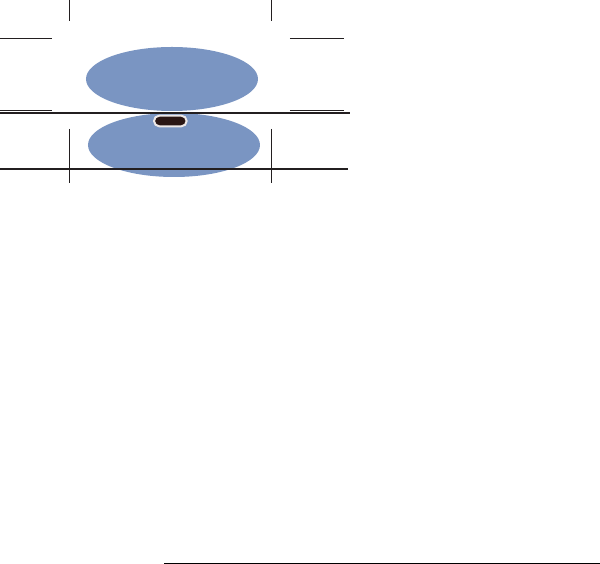
AP300 is designed to provide 360 degree omni-directional coverage as illustrated below. Plan place-
ment with this pattern in mind.
Figure 7: Coverage Pattern for AP300 When Ceiling Mounted
Most installations receive the best coverage using the following guidelines:
Install APs toward the center of the building.
Place APs about 80 feet apart.
Do not install APs near metal objects, such as heating ducts, metal doors, or electric service panels.
For best coverage, orient antennas as shown in Figure 6.
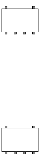
Attach the Provided Antennas
All AP300s have six external antenna ports, labeled 1 - 6. These units operate with six antennas
attached, even though some configurations don’t use all six. Instead of attaching an antenna, you can
cap unused antenna connectors with 50 ohm Reverse Polarity SMA terminators. (For a list of approved
terminators, see http://www.merunetworks.com/merusupport.) Meru supplied antennas are suitable
only for indoor use unless they are mounted in an outdoor enclosure (see Mount AP300 in a Hoffman
Enclosure). To achieve the best performance from your AP300, position antennas at a 90 degree angle
relative to each other as shown in Figure 6. The antennas do not have to be oriented exactly as shown
in the figure, but it is important to maintain the relative angles. If for some reason you are unable to
maintain those angles, the network still operates, but you may experience up to 20% drop in throughput
depending on the antenna orientation.
ceiling
floor
18 Meru Access Point Installation Guide © 2010 Meru Networks, Inc.
Install the AP300
AP1000 Beta Test
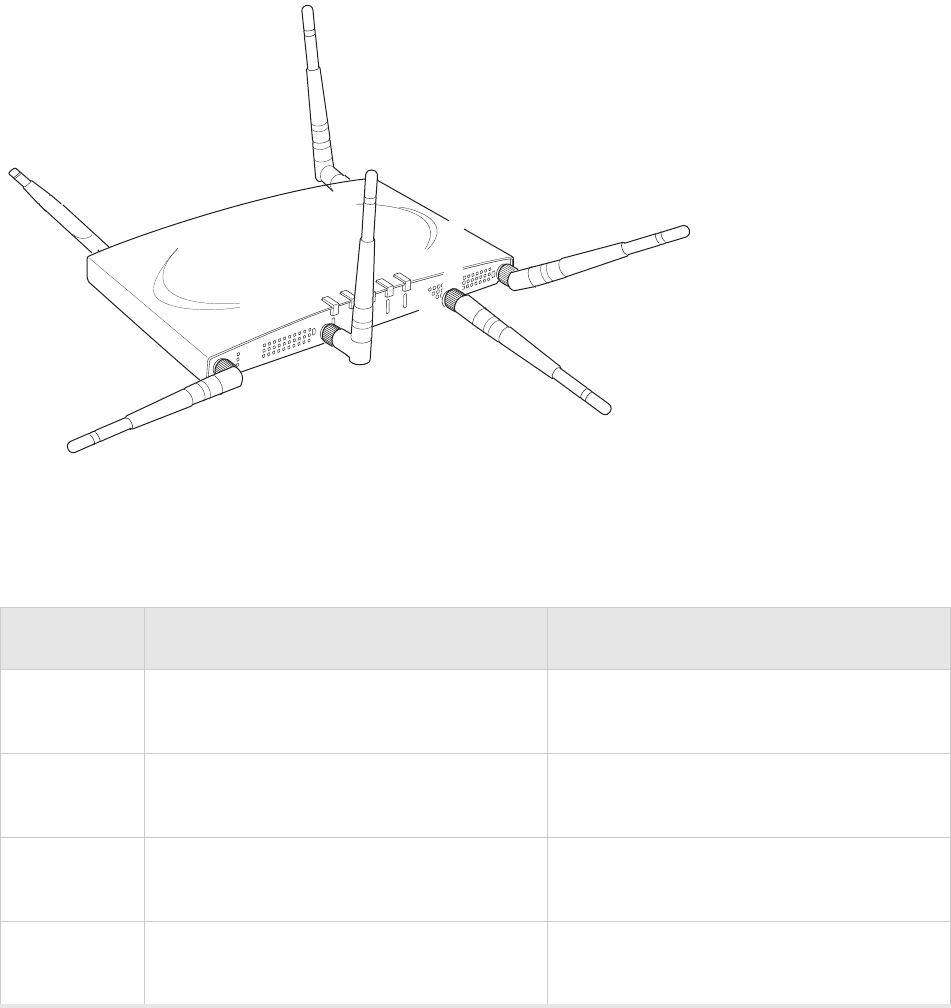
Figure 6: AP320, AP311 or AP302 Antennas 1-6 in Ceiling and Wall Mount Configuration
The following antenna connections are used during operation of the AP320, AP311, and AP302. Note
that PSM3x APs will only have four antennas, rather than the typical six.
Table 1: AP300 With Two Radios and Corresponding Antennas
Model Radio 1 (Ant4, Ant5, Ant6) Radio 2 (Ant1, Ant2, Ant3)
PSM3x a/b/g/n with 3 dual band omni-directional
antennas (only one radio can be N) Spectrum radio with one omni-directional
antenna.
AP320 a/b/g/n with 3 dual band omni-directional
antennas a/b/g/n with 3 dual band omni-directional
antennas
AP311 a/b/g/n with 3 dual band omni-directional
antennas (only one radio can be N) a/b/g/n with 3 dual band omni-directional
antennas (only one radio can be N)
AP302 a/b/g with 3 dual band omni-directional
antennas a/b/g with 3 dual band omni-directional
antennas
A
2
A
2
A
L
A
N
R
F
1
R
F
2
2
1 (horizontal)
6 (vertical)
2 (horizontal)
4 (horizontal)
3 (vertical)
5 (horizontal)

Install the AP300
© 2010 Meru Networks, Inc. Installing AP300 19
AP1000 Beta Test
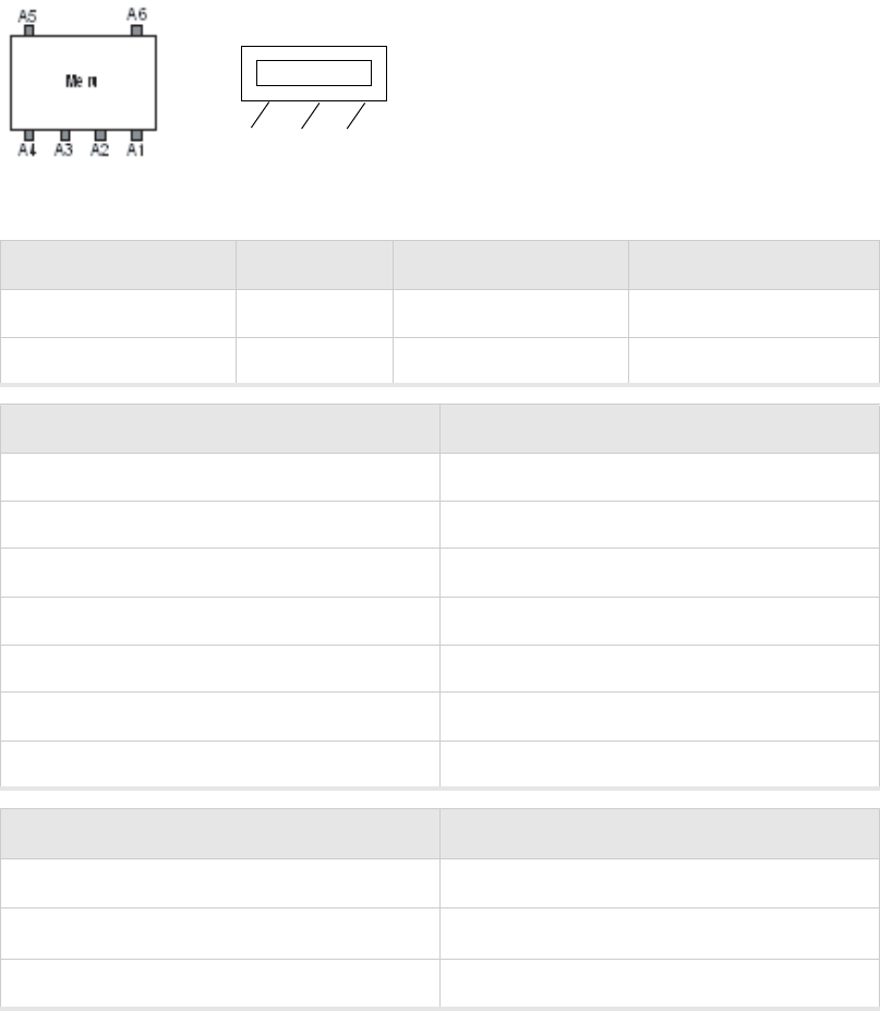
Table 2: AP310 With One Radios and Corresponding Antennas
The AP310 has six external antenna ports labeled 1 - 6. However, AP310 uses only three of those
antennas and the unused antenna connectors are blocked. Figure 7 illustrates the recommended
antenna configuration for the AP310.
Figure 7: AP310 Antennas 1-3
The following antenna connections are used during operation of the AP310.
Do not leave any antenna connectors unterminated. All connectors on the AP must be terminated with
antennas or with 50 ohm Reverse Polarity SMA terminators. (For a list of approved terminators, see
http://www.merunetworks.com/merusupport.
The attached antennas must be the same model; if you replace one antenna, replace them all.
Model Radio 1 (Ant1, Ant2, Ant3)
AP310 a/b/g/n with 3 dual band omni-directional antennas
Radio 1 Antenna Connectors for AP310 Radio2 Antenna Connectors for AP310
Ant1, Ant2, Ant3 NA
A
2
A
2
A
L
A
N
R
F
1
R
F
2
2
1 (horizontal)
2 (horizontal)
3 (vertical)
does not matter
does not matter
does not matter
20 Meru Access Point Installation Guide © 2010 Meru Networks, Inc.
Install the AP300
AP1000 Beta Test
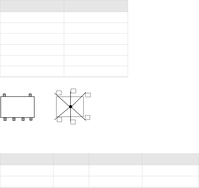
Install the Remote Antenna Mount (optional)
Use the optional Meru Remote Antenna Mount (ACC-ANT-MIMO-MNT) for one or both AP300 radios to
remotely connect the AP300 antennas. The Remote Antenna Mount allows you to relocate either your
current antennas or the optional high-gain dipole antennas to a location with clearer signal paths to
the other wireless devices in your network. The Remote Antenna Mount can be installed either below
the ceiling tile or on the wall. The default orientation for the mount is suitable for a ceiling mount,
but you can attach the mount to a wall with some modifications.
Use one mount per radio; for example AP310 needs one unit, and AP320 needs two units.The Remote
Antenna Mount uses low-loss plenum rated LMR195 cable and SMA connectors. To order this unit,
contact your Meru sales representative and refer to part number ACC-ANT-MIMO-MNT.
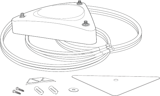
Figure 8: Remote Antenna Mount
The remote antenna mount kit includes:
Antenna stand with attached cable. The three antenna SMA female connectors on the Antenna
Mount support AP300 antenna diversity. This feature gives the client the ability to automatically
choose the antenna receiving the strongest signal.
Triangular ceiling mount clip for attaching to hanging ceiling (includes bolt assembly)
Three self-adhesive pads for the bottom of the unit (over the screws)
Two wall mount screws with anchors
Ceiling Mount Template
Installation diagram
Install the Remote Antenna Mount on the Ceiling
To connect the Remote Antenna Mount to the ceiling, refer to the installation diagram from the ship-
ping box while following these steps:
1. Attach the shorter end of the screw to the center hole on the back of the Antenna Mount.
2. Remove the designated ceiling tile.
00224
Install the AP300
© 2010 Meru Networks, Inc. Installing AP300 21
AP1000 Beta Test
3. Using the template, drill holes in the ceiling tile.
4. Replace the ceiling tile.
5. Remove a ceiling tile adjacent to the newly drilled tile for access purposes.
6. Feed the Antenna Mount cable through the larger hole in the ceiling tile until the Antenna Mount
is flush with the ceiling. The screw should now be visible above the ceiling tile (through the second
hole).
7. Place the triangular plate above the ceiling tile with the screw aligned through the plate.
8. Drop the washer onto the screw and tighten the bolt.
The Antenna Mount is now connected to the ceiling.
9. Replace the adjacent tile.
10. Connect the three Remote Antenna Mount cables to the appropriate connectors on the AP300. Be
sure to connect the three antennas that correspond to one radio. Radio 1 uses A1, A2, A3 and Radio
2 uses A4, A5, A6.
11. Attach three antennas that shipped with AP300 to the three connectors on the triangular remote
device. See Figure 8.
Install the Remote Antenna Mount on a Wall
1. Reorient the cable on the Remote Antenna Mount by removing the three screws on the back,
removing the small cover, reorienting the cable and then replacing the three screws. Discard the
small cover.
2. Connect the three Remote Antenna Mount cables to the appropriate ports on the AP300. Be sure to
connect the three antennas that correspond to one radio. Radio 1 uses A1, A2, A3 and Radio 2 uses
A4, A5, A6. PSM3x devices only utilize A1, A2, A3, and A5.
3. Attach three of the antennas that shipped with AP300 to the three ports on the triangular remote
device.
4. Orient the connected AP300 horizontally so that you can read the Meru logo without tilting your
head at 90 degrees - this orientation provides optimum MIMO performance.
Meru
A1
A5 A6
A4 A3 A2
Meru
A1
A5 A6
A4 A3 A2
22 Meru Access Point Installation Guide © 2010 Meru Networks, Inc.
Install the AP300
AP1000 Beta Test
Install External ACC-ANT-MIMO-MNT Antenna with Three Connectors
(optional)
You can optionally use an external antenna setup with your AP300 if the controller and APs are running
System Director 3.6.1MR4 and later. Meru supports this antenna for use on one radio using 802.11n
MIMO. An AP300 with one radio, for example AP310, needs one antenna. An AP300 with two radios, for
example AP320, needs two antennas. Radio One antenna cables connect to ports A1, A2, and A3. Radio
Two cables connect to ports A4, A5, and A6. There is no preferred cabling connection; all three cables
are the same.
Calculate the antenna gain for the ACC-ANT-MIMO-MNT antenna by referring to the next three charts:
Band of Operation Gain Vertical Beamwidth Horizontal Beamwidth
2.40-2.483 GHz 2.5dB 55 degrees 360 degrees
5.15-5.85 GHz 4dB 60 degrees 360 degrees
Using This Cable Type with 2.4 GHz Calculate This Loss per Foot
RG174 0.60 dB
RG316 0.48 dB
LMR100 0.39 dB
LMR200 0.17 dB
LMR240 0.13 dB
LMR400 0.066 dB
LMR600 0.043 dB
Using This Cable Type with 5 GHz Calculate This Loss per Foot
RG174 1.02
RG316 0.76
LMR100 0.59 dB

Install the AP300
© 2010 Meru Networks, Inc. Installing AP300 23
AP1000 Beta Test
LMR200 0.24 dB
LMR240 0.19 dB
LMR400 0.100 dB
LMR600 0.066 dB
Using This Cable Type with 5 GHz Calculate This Loss per Foot
24 Meru Access Point Installation Guide © 2010 Meru Networks, Inc.
Install the AP300
AP1000 Beta Test
Install Remote ACC-ANT-6ABGN-24 Antenna with Six Connectors
(optional)
You can optionally use an external antenna setup with your AP300 if the controller and APs are running
System Director 3.6.1MR4 and later. Meru supports this antenna for use on AP300s with two radios, for
example AP320. This antenna has six connectors to connect to both radios to a dual-radio AP300 and
it supports 802.11n MIMO operation.
The six cables on the ACC-ANT-6ABGN-24 antenna are already tagged with the numbers 1 - 6. Connect
the antenna cables to the AP antenna ports as shown here:
Calculate the antenna gain for the ACC-ANT-6ABGN-24 antenna by referring to the next three charts:
Meru AP300 Antenna
Connector Antenna Cable Numbered
A1 6
A2 5
A3 4
A4 3
A5 2
A6 1
Band of Operation Gain Vertical Beamwidth Horizontal Beamwidth
2.40-2.483 GHz 2.5dB 55 degrees 360 degrees
5.15-5.85 GHz 4dB 60 degrees 360 degrees
123
46
5
antenna
AP300
A5
A3A4 A2 A1
A6

Install the AP300
© 2010 Meru Networks, Inc. Installing AP300 25
AP1000 Beta Test
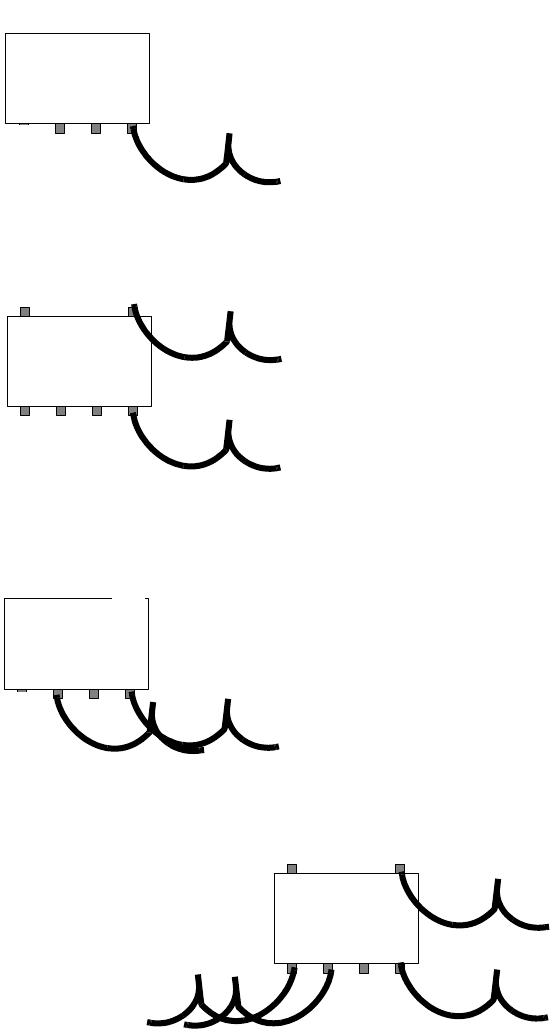
Install Antennas With One Connector (optional)
You can optionally use an external antenna setup with your AP300 if the controller and APs are running
System Director 3.6.1MR4 or 4.0.
When deploying an AP300 with only one antenna per radio, AP300 cannot support 802.11n MIMO oper-
ation. Also, any antenna ports that are not used to connect to an antenna must be terminated with 50
ohm Reverse Polarity SMA terminators. (For a list of approved terminators, see http://www.merunet-
works.com/merusupport.) Connect the antenna using one cable per radio as described in the table
below. These instructions can be used to replace an AP200 existing antenna configuration with an
AP300. For these instructions, each port on the AP300 is identified by a label A1 to A6.
Using This Cable Type with 2.4 GHz Calculate This Loss per Foot
RG174 0.60 dB
RG316 0.48 dB
LMR100 0.39 dB
LMR200 0.17 dB
LMR240 0.13 dB
LMR400 0.066 dB
LMR600 0.043 dB
Using This Cable Type with 5 GHz Calculate This Loss per Foot
RG174 1.02
RG316 0.76
LMR100 0.59 dB
LMR200 0.24 dB
LMR240 0.19 dB
LMR400 0.100 dB
LMR600 0.066 dB
26 Meru Access Point Installation Guide © 2010 Meru Networks, Inc.
Install the AP300
AP1000 Beta Test
AP Has One BG or A Radio, One Antenna
AP Has Two Radios (BG and A), One Antenna For Each
AP Has One Radio, Two Antennas
AP Has Two Radios, Four Antennas
Meru
A1
A5 A6
A4 A3 A2
(BG or A radio antenna)
Meru
A1
A5 A6
A4 A3 A2
(BG radio antenna)
(A radio antenna)
Meru
A1
A5 A6
A4 A3 A2
(BG or A radio antenna)
(BG or A radio antenna)
Meru
A1
A5 A6
A4 A3 A2
(BG radio antenna)
(A radio antenna)
(A radio antenna)
(BG radio antenna)

Install the AP300
© 2010 Meru Networks, Inc. Installing AP300 27
AP1000 Beta Test
Install the Access Point
AP300 ships with a detachable mounting bracket. The AP300 is designed to be compatible with brackets
supplied by Meru and by other vendors as follows. The AP300 mounts directly on the AP150 mounting
bracket. If you are replacing AP200s/AP300s, the AP300 bracket can be mounted on the old
AP200s/AP300s bracket with included shoulder screws; you don’t need to remove the old brackets.
AP300 can also be directly mounted on third-party brackets such as Proxim AP4000 and Cisco standard
brackets.
You can mount an AP300 in the following ways:
Mount AP300 Horizontally on a Shelf
Mount AP300 Vertically on a Wall
Mount AP300 Below a Suspended Ceiling
Mount AP300 Above a Suspended Ceiling (Plenum)
Mount AP300 Above a Suspended Ceiling (Plenum)
Mount AP300 in a Hoffman Enclosure
Mount AP300 Horizontally on a Shelf
When mounting an AP300 horizontally, remove the mounting bracket. Be sure to position the antennas
vertically when an AP300 sits on a surface.
Mount AP300 Vertically on a Wall
Note:
If you are replacing AP150s, you can use the existing brackets: the AP150 and AP300 use the
same bracket. If you are replacing AP300s, the AP300 bracket can be attached to the old bracket with
included shoulder screws; you don’t have to remove the old brackets. This bracket will also mount
seamlessly into the Proxim AP4000 bracket and standard Cisco brackets.
To mount an AP300 on a wall:
1. Using the bracket holes as a guide, mark the location on the wall for the two AP bracket mounting
screws. If possible, center the mounting screws on a wall stud. If you do not center the mounting
screws on a wall stud, use plastic wall anchors. Orient the AP300 horizontally so that you can read
the Meru logo without tilting your head at 90 degrees - this orientation provides optimum MIMO
performance.
2. Drill holes at the locations you marked:
—3/16-inch holes if you are using plastic anchors
—1/8-inch holes if you are using only the screws
3. If you are using plastic anchors, install them in the holes.
4. Screw in the screws most of the way.
5. Mount the bracket on the screws, placing the circular portion of the keyhole mounts over the screw
heads and sliding the bracket down.
6. Connect one end of the Ethernet cable to the switch and the other end to the AP300 Ethernet port.
28 Meru Access Point Installation Guide © 2010 Meru Networks, Inc.
Install the AP300
AP1000 Beta Test
7. If you are not using a PoE device, connect an external power supply to the power connector and
plug it into the wall.
Mount AP300 Below a Suspended Ceiling
The optional suspended ceiling mounting kit (ACC-MNT-SCRMKIT) allows the AP300 mounting bracket
to attach to suspended ceiling T-rails (see Figure 9).
Note:
To comply with NEC code, attach a grounding wire to any of the screws used to attach the AP300
to the mounting bracket.
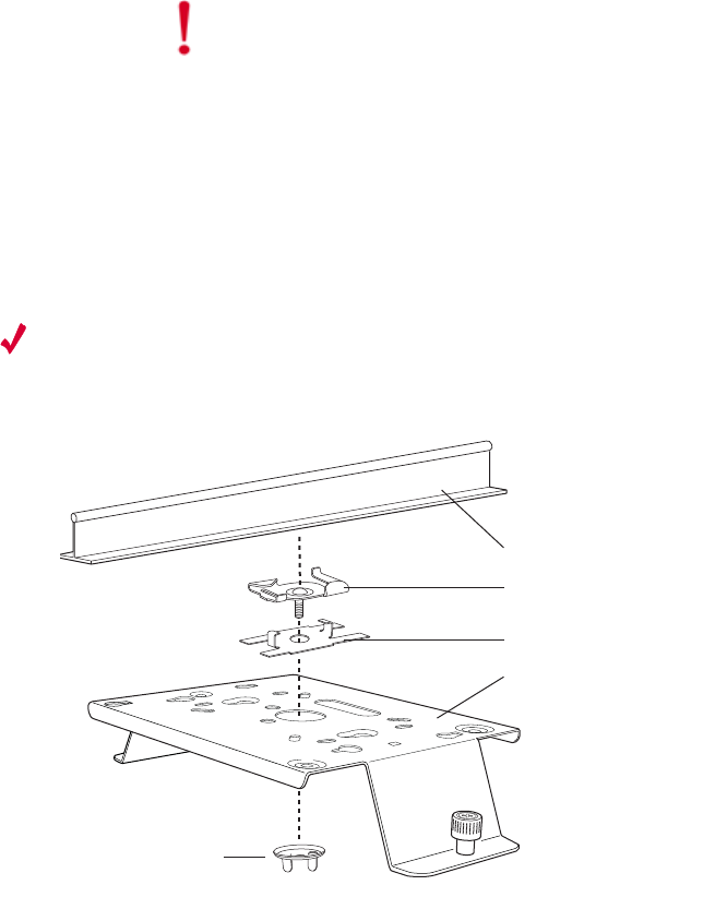
Figure 9: Mounting any AP to a Suspended Ceiling Rail using ACC-MNT-SCRMKIT
To mount an AP300 below a suspended ceiling:
1. Determine the location on the ceiling rail where the AP will be mounted and remove the ceiling
tiles.
2. Place each of the two caddy fasteners on the ceiling T-rail and twist to attach to the rail.
3. Adjust the distance between the caddy fasteners by using the mounting bracket holes as a guide.
4. Tighten the caddy fasteners in place using a standard screwdriver. Do not overtighten.
5. Place each spacer on the caddy fastener stud. The spacer legs should contact the ceiling T-rail.
6. Align the mounting bracket keyholes with the caddy fastener studs and slide the AP300 to the
narrow end of the hole.
7. Attach a keps nut to each caddy fastener stud and hand tighten. Do not overtighten.
Caution!
Be sure to connect the Ethernet cable to the Ethernet port; the cable can
mistakenly be plugged into the Console port. If you do this, the AP won’t power up.
Suspended ceiling T-rail
Caddy fastener
Spacer
Mounting bracket
Washer
00257

Install the AP300
© 2010 Meru Networks, Inc. Installing AP300 29
AP1000 Beta Test
8. Align the AP300 mounting posts over the circular portion of the keyhole mounts, push the AP in and
slide the AP down until it engages with the locking detents (see Figure 9). You should hear it snap
in place.
9. For each antenna, loosen the knurled ring at the base of the antenna, orient the antenna and then
retighten the ring.
10. Connect one end of the PoE 100BaseT Ethernet cable to the 100/1000 Ethernet connector.
Caution!
Be sure to connect the Ethernet cable to the Ethernet port; the cable can
mistakenly be plugged into the Console port. If you do this. the AP won’t power up.
30 Meru Access Point Installation Guide © 2010 Meru Networks, Inc.
Install the AP300
AP1000 Beta Test
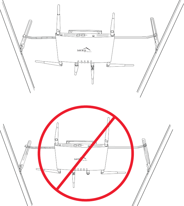
Mount AP300 Above a Suspended Ceiling (Plenum)
Use the optional T-bar box hanger mounting kit (see Mounting Brackets for the part number) to mount
AP300 above suspended ceiling T-rails (see Figure 10 and Figure 11). The installation attaches the T-
bar box hanger to the ceiling rails and then the AP300 attaches to the T-bar box hanger. We recommend
that you mount the AP300 no more than half way up the supports as shown in both Figure 10 and
Figure 11. Also note that AP300 mounted above the ceiling has about 2-3 dBm less RF coverage than
AP300 mounted under the ceiling.
Figure 10: AP300 Mounted Above a Suspended Ceiling Face Down
The second example above is mounted too high on the support rails, which could cause the rails to
bend.
00243
00233
Install the AP300
© 2010 Meru Networks, Inc. Installing AP300 31
AP1000 Beta Test
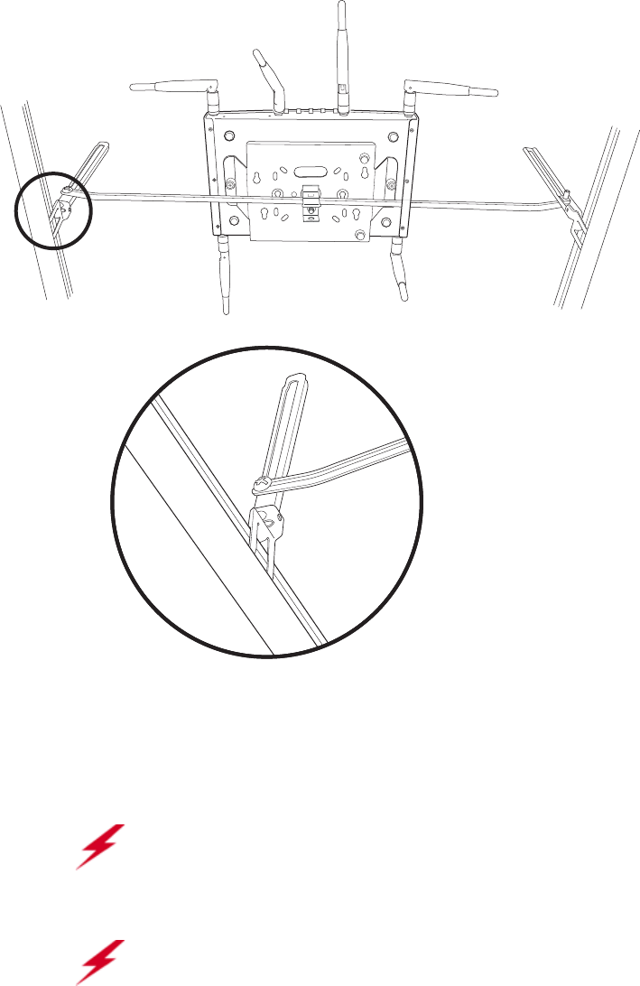
Figure 11: AP300 Mounted Above a Suspended Ceiling Face Up
The AP300 with the metal enclosure exposed meets the requirements for fire resistance and low
smoke-generating characteristics required by Section 300-22(C) of the National Electrical Code (NEC)
for installation in a building’s environmental air space.
You may need to modify thicker tiles to support this installation.
Warning!
When installed in air-handling spaces, such as above a suspended ceiling,
power the AP300 only with a PoE, not a power supply. See Power Supplies for part
numbers.
Warning!
Any Fast Ethernet (FE) cables installed in air-handling spaces should be
suitable under NEC Article 800.50 and marked accordingly for use in plenums and air-
handling spaces with regard to smoke propagation, such as CL2-P, CL3-P, MPP (Multi
Purpose Plenum), or CMP (Communications Plenum). Use Ethernet cable that meets
the requirements for operating in plenums and environmental air space in
accordance with Section 300-22(C) of the NEC.
00232
32 Meru Access Point Installation Guide © 2010 Meru Networks, Inc.
Install the AP300
AP1000 Beta Test
To mount an AP300 above the ceiling with the optional T-bar kit, follow these steps:
1. Determine the location on the ceiling rails where the AP will be mounted and remove the ceiling
tile.
2. Unpack the T-bar hanger kit and unfold the legs of the T-bar hanger.
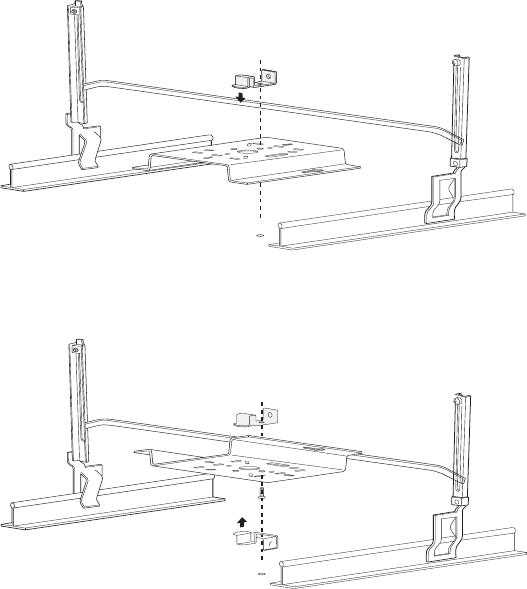
3. Locate the bracket mounting clip holes on the mounting bracket (see Figure 10). One hole attaches
the bracket perpendicular to the box hanger; the other mounts the bracket parallel to the box
hanger.
4. Attach the U-joint of the clip to the T-bar and snap in place (see Figure 12).
Figure 12: Attaching the Mounting Bracket to the Box Hanger for Face Up Orientation
.
Figure 13: Attaching the Mounting Bracket to the Box Hanger for Face Down Orientation
.
5. Pass the long end clip through the large center hole to the underside of the mounting bracket clip
and then attach the bracket to the clip using the supplied screw (see Figure 12 for orientation).
00104
00104

Install the AP300
© 2010 Meru Networks, Inc. Installing AP300 33
AP1000 Beta Test
6. Hold the AP300 next to the mounting bracket to estimate the height of the T-bar box hanger. You
need to provide enough clearance for the external antennas that point down, while mounting the
T-bar on the lower half of the support rails for stability.
7. Adjust the height of the box hanger using the height adjusting screws (see Figure 9).
8. Clip the box hanger T-rail clips to the ceiling rails, making sure they are securely attached.
9. Connect a drop wire to a building structural element and through the hole provided in the bracket
mounting clip. The U.S. National Electrical Safety Code requires this additional support.
10. Connect the posts of the AP300 to the three keyholes of the mounting bracket and slide into the
keyhole, ensuring the locking detent is engaged. You will hear a click.
11. For each antenna, loosen the knurled ring at the base of the antenna, point the antenna down, then
retighten the ring.
12. Connect one end of the PoE Ethernet cable to the Ethernet connector.
13. Check that the AP300 is operating correctly before replacing the ceiling tile to the ceiling. Verify
correct operating using the LEDs, as shown in Check AP300 LED Activity.
Mount AP300 in a Hoffman Enclosure
Meru has designed a custom mounting bracket compatible with a Hoffman enclosure (www.hoffmanon-
line.com). This bracket is available exclusively through Meru and orderable as part number ACC-AP300-
BHE. To mount an AP300 in a Hoffman enclosure, follow these steps:
1. Place AP300 upside down on a soft flat surface.
2. Remove and discard the wall/ceiling mounting bracket.
3. Attach either the provided antennas or an external antenna.
4. Remove and discard the four rubber feet.
5. Position the Hoffman bracket (ACC-AP300-BHE) onto the back of the AP300 with the four Hoffman
mounting screws facing downwards.
Caution!
Be sure to connect the Ethernet cable to the Ethernet port; the cable can
mistakenly be plugged into the Console port. If you do this. the AP won’t power up.
Note:
Use a shielded Cat 5e (or greater) Ethernet cable in order to comply with
international electromagnetic emissions limits.
34 Meru Access Point Installation Guide © 2010 Meru Networks, Inc.
Check AP300 LED Activity
AP1000 Beta Test
Figure 14: Hoffman Bracket ACC-AP300-BHE
6. Using a Phillips screw driver, attach the bracket using the two supplied 6-32 3/16 SEMS screws.
7. Flip the assembly over and mount into the Hoffman enclosure, attach the Ethernet cable to the
AP300 rotating the assembly to place the Ethernet cable within the enclosure.
8. Using a Phillips screw driver, tighten the four bracket screws to the enclosure.
9. Adjust the antennas as needed.
Check AP300 LED Activity
When AP300 first connects to the controller (and any time the access point is rebooted), the AP initial-
izes and is then programmed by the controller. When the AP first powers up, all LEDs are green.
Figure 15: AP300 Status LEDs
After the AP300 is connected, check the status of the LEDs. The functions of the five LEDs are described
below.
00230
A
3
A
2
L
A
N
S
T
T
A
P
W
R
R
F
1
R
F
2
00217
P
W
R
S
T
A
T
L
A
N
R
F
1
R
F
2

Check AP300 LED Activity
© 2010 Meru Networks, Inc. Installing AP300 35
AP1000 Beta Test
AP300/AP300i LED Descriptions
LED Function Troubleshooting
Power off—no power
green—presence of power
Status
off—no power
green—booting stage 1
blinking green and off—booting stage 2
blinking green and white—discovering the
controller
blinking green and blue—downloading a
configuration from the controller
blinking blue and off—AP is online and
enabled, working state
blinking red and yellow—failure; consult
controller for alarm state
If the status LED is blinking red and
yellow, there is an alarm on the AP.
Determine what the alarm is by
clicking Monitor > Dashboard >
Alarms and looking at the AP alarms.
You can also use the CLI commands
show alarm and show log.
LAN
off—no power or no link
green—link status OK (at any speed)
green/blinking—activity (at any speed)
red—auto negotiation failure
If the LAN LED is red, auto
negotiation failed. This means that
you have a problem with cabling or
with the AP’s switch.
Radio 1
Radio 2
off—no radio present
green—radio enabled
green blinking—data activity
yellow—disabled or in scanning mode
red—failure
If one of the radio LEDs is yellow, it is
either disabled or in scanning mode.
To see if the AP is disabled, click
Configuration > Wireless > Radio >
select a radio and then look at
Administrative Status, which should
be set to Up. To see if the AP is in
Scanning Mode, click Configuration >
Wireless > Radio > select a radio and
look at AP Modes, which should be set
to Normal Mode.
If one of the radio LEDs is red, the
radio failed. Check the alarms
(Monitor > Dashboard > Alarms),
diagnostics (Monitor > Diagnostics >
Radio), and statistics (Monitor >
Dashboard > Radio) on the AP’s
controller to determine the cause.

36 Meru Access Point Installation Guide © 2010 Meru Networks, Inc.
Where to Go From Here
AP1000 Beta Test
Change LED Appearance
If you want to change the appearance of the LEDS, follow these steps:
1. From the controller, click Configuration > Devices > AP, and then select the AP.
2. Select one of these settings for the LED Mode setting:
—Normal: LEDs are as described below
—Node ID: Not supported in release 4.1
—Blink: Sets all LEDs flashing; this is useful to locate an AP
—Dark: Turns off all LEDs
3. Click OK.
Where to Go From Here
Now that the AP1000 is installed, refer to the Meru System Director Getting Started Guide for instruc-
tions on initializing the hardware. Return to this chapter to check the status of the LEDs once the WLAN
is operational.