Mesa Engineering ATRG2-MOD Field disturbance device for detecting presence and speed of passing vehicles User Manual
Mesa Engineering, Inc. Field disturbance device for detecting presence and speed of passing vehicles
UserManual.wiki
>
Mesa Engineering
>
ATRG2 MOD User Manual
User Manual
Navigation menu
Upload a User Manual
Namespaces
Wiki Guide
HTML
PDF
Info
Views
User Manual
Discussion / Help
Navigation

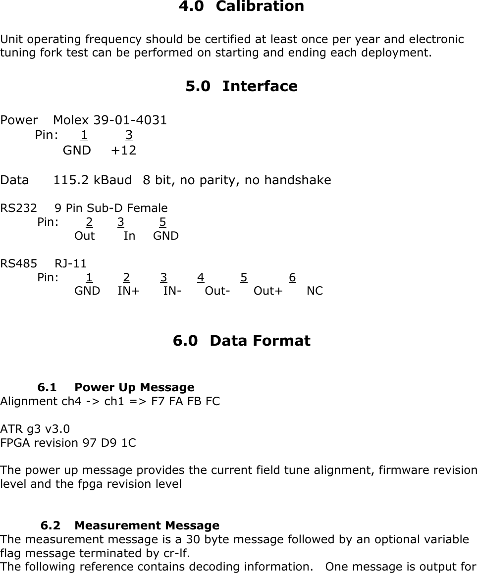
![7.0 Command Guide Commands are an ASCII coded message terminated by a cr. Undefined command strings get a ? cr-lf response. Help H cr causes a dump of available commands and their syntax/ Ax Analog channel lock 0-Float {default}, 1-DopA approach 2-DopB recede, 3-PhaA, 4-PhaB Cx Calibrator function 0- terminate 1-4 Tuning Fork profile# 5-8 (151,75,38,19)Mph (243,123,60,30)Kmh Calibrator profile# Dmx DebugTrace mode control 0-normal operation {default}, 1-sequential states, 2-packet values TRACE state symbols: ! =squelch transition + =1 Meter marker annnn =SQLbreak value p =arriving measure packet l =speedlock set t =track timeout r =direction reversal z =short track abort [ =track drop start ~ =drop timeout ] =drop normal w =wait state entered Jxxyy Manual analog channel setting xx = channel select 01-DopB{approach}, 02-DopA{recede}, 03-I, 04-Q yy = channel sensitivity, FF=maximum, 00=minimum L Force Watchdog activation Q Compact information summary request Rn Read CPLD channel n, 0 thru 6 inclusive Wnyy Write CPLD register n with value yy S Simulate Vehicle: S+v Approaching, S-v Receding TNnn Set Analog alignment threshold to nn TA perform verbose analog channel alignment T? report current analog channel settings](https://usermanual.wiki/Mesa-Engineering/ATRG2-MOD/User-Guide-1950035-Page-10.png)